
AW-RP50 - Remote control PANASONIC - Free user manual and instructions
Find the device manual for free AW-RP50 PANASONIC in PDF.


| Product Type | Remote Control for PTZ Cameras |
| Brand | Panasonic |
| Model | AW-RP50 |
| Dimensions (W x H x D) | Approx. 430 x 88 x 300 mm |
| Weight | Approx. 3.2 kg |
| Power Supply | AC 100-240 V, 50/60 Hz (via included adapter) |
| Power Consumption | Approx. 30 W |
| Control Interface | RS-422 / RS-485 (via RJ-45) |
| Compatible Cameras | Panasonic AW series (e.g., AW-HE130, AW-UE70) |
| Display | Backlit LCD, 3.5-inch color |
| Joystick | 3-axis (pan, tilt, zoom) |
| Buttons | Dedicated camera control keys, preset recall, menu navigation |
| Memory Presets | Up to 100 per camera |
| Mounting | Desktop or 19-inch rack mount (ears included) |
| Operating Temperature | 0°C to 40°C (32°F to 104°F) |
| Cleaning | Wipe with a dry, soft cloth; avoid liquids |
| Safety Certifications | CE, FCC Class A |
| Spare Parts Availability | Contact Panasonic service center |
| Warranty | 1 year (check local regulations) |
Frequently Asked Questions - AW-RP50 PANASONIC
User questions about AW-RP50 PANASONIC
0 question about this device. Answer the ones you know or ask your own.
Ask a new question about this device
Download the instructions for your Remote control in PDF format for free! Find your manual AW-RP50 - PANASONIC and take your electronic device back in hand. On this page are published all the documents necessary for the use of your device. AW-RP50 by PANASONIC.
USER MANUAL AW-RP50 PANASONIC
Operating Instructions
Remote Camera Controller
Model No. AW-RP50N

Before use .... 3
Overview 3
Trademarks and registered trademarks ....3
About copyright and licence ....3
Concerning the ratings display ....3
Disclaimer of warranty 3
Network security....3
How to turn the power of the remote cameras on and off 4
Setting and operating the preset memories ...... 6
Registering data in the preset memories ....6
Executing the preset data ....7
Deleting the preset memory data ....7
Selecting the settings for a selected remote camera 8
Setting the gain ....8
Setting the pedestal 8
Setting the white balance 9
Setting the black balance ....12
Setting the shutter speed ....13
Setting the detail 13
Setting the shooting mode ....14
Specifying the color bars 14
Operating the menu items of the selected remote camera....15
Setting the USER buttons 16
Tally settings 17
Setting the functions ...... 18
Setting the remote camera operations ....19
Setting the speed at which to move to the position set by the preset memory ....21
Setting the operations to be performed when a preset operation is executed 21
Returning the remote cameras to their home position .....21
Adjusting the panning, tilting, zooming and focusing speed .....21
Setting the movement range of the remote camera (limiter function) 22
Controlling the peripheral devices connected to the remote cameras....24
Adjusting the minimum lens zoom start speed ....25
Exercising external control over the preset memory data ..... 25
Locking the button operations ....26
Adjusting the LCD panel backlight 26
Setting linkup with the switcher 27
Switcher network settings 27
Link setting 28
Setting the functions when the unit is linked with the switcher 29
Setting the image output and image input 29
Switcher settings 30
Setting for the information to be displayed on the OSD ....33
Checking the equipment alarm information...... 35
Returning the unit to its factory status .... 36
Control interface for external devices 37
Setup Software 38
Installing the software ....38
IP settings 38
Saving and loading data 41
Referencing the network environment 42
Table of menu items 43
How the model's Operating Instructions manuals are configured
- The manual of this Remote Camera Controller (hereafter, "the unit") is divided into two manuals: one is the (this manual in the CD-ROM), and the other is the . Before installing the unit, be sure to read the to ensure that the unit is installed correctly.
- For the purposes of this manual, the model numbers of the units are given as listed in the table below.
| Model number of unit | Model number given in manual | Model number of unit | Model number given in manual | Model number of unit | Model number given in manual |
| AW-HS50N AW-HS50 AW-E650P AW | -E650 AW-PH650N AW | W-PH650 | |||
| AW-HE50HN | AW-HE50 AW-E750P AW-E750 AW | IF400G AW | -IF400 | ||
| AW-HE50SN | AW-HE50 | AW-E860N AW-E860 | AK-HC1500G | AK-HC1500 | |
| AW-HE100N | AW-HE100 AW-PH360N AW-PH360 | AK-HC1800G | AK-HC1800 | ||
| AW-HE870N AW-HE870 AW-PH400P | AW-PH400 | ||||
| AW-E350P AW-E350 AW-PH405N AW | W-PH405 |
- In these instructions, the phrases “pan-tilt head and camera combination” and “camera integrated with a pan-tilt head” are both referred to collectively as “remote camera” except in places where specific equipment is mentioned.
Overview
This unit is a controller designed to control remote cameras (cameras integrated with pan-tilt heads) and pan-tilt head systems (which consist of pan-tilt heads and the cameras mounted on them).
By means of an IP connection, an operating environment where the unit is tied in with the AW-HE50 HD integrated camera and AW-HS50 compact live switcher is achieved. When IP connections are used, the unit can be used to control up to 100 remote cameras.
When serial connections are used, up to five remote cameras and pan-tilt head systems can be controlled.
■ Trademarks and registered trademarks
- Microsoft, Windows, Windows Vista, Windows 7 and Internet Explorer are either registered trademarks or trademarks of Microsoft Corporation in the United States and other countries.
- Intel and Intel Core are trademarks or registered trademarks of Intel Corporation in the United States and other countries.
- Adobe and Reader are either registered trademarks or trademarks of Adobe Systems Incorporated in the United States and/or other countries.
- Other names of companies and products contained in these Operating Instructions may be trademarks or registered trademarks of their respective owners.
■ About copyright and licence
Distributing, copying, disassembling, reverse compiling, reverse engineering, and also exporting in violation of export laws of the software provided with this unit are expressly prohibited.
■ Concerning the ratings display
The unit's name, model number and electrical ratings are indicated on its bottom panel.
■ Disclaimer of warranty
IN NO EVENT SHALL Panasonic System Networks Co., Ltd. BE LIABLE TO ANY PARTY OR ANY PERSON, EXCEPT FOR REPLACEMENT OR REASONABLE MAINTENANCE OF THE PRODUCT, FOR THE CASES, INCLUDING BUT NOT LIMITED TO BELOW:
① ANY DAMAGE AND LOSS, INCLUDING WITHOUT LIMITATION, DIRECT OR INDIRECT, SPECIAL, CONSEQUENTIAL OR EXEMPLARY, ARISING OUT OF OR RELATING TO THE PRODUCT; ② PERSONAL INJURY OR ANY DAMAGE CAUSED BY INAPPROPRIATE USE OR NEGLIGENT OPERATION OF THE USER; ③ UNAUTHORIZED DISASSEMBLE, REPAIR OR MODIFICATION OF THE PRODUCT BY THE USER; ④ INCONVENIENCE OR ANY LOSS ARISING WHEN IMAGES ARE NOT DISPLAYED, DUE TO ANY REASON OR CAUSE INCLUDING ANY FAILURE OR PROBLEM OF THE PRODUCT; ⑤ ANY PROBLEM, CONSEQUENTIAL INCONVENIENCE, OR LOSS OR DAMAGE, ARISING OUT OF THE SYSTEM COMBINED BY THE DEVICES OF THIRD PARTY; ⑥ ANY INCONVENIENCE, DAMAGES OR LOSSES RESULTING FROM ACCIDENTS CAUSED BY AN INADEQUATE INSTALLATION METHOD OR ANY FACTORS OTHER THAN A DEFECT IN THE PRODUCT ITSELF: ⑦ LOSS OF REGISTERED DATA CAUSED BY ANY FAILURE; ⑧ ANY DAMAGES, CLAIMS, ETC. DUE TO LOSS OR LEAKAGE OF THE SETTING DATA SAVED ON THIS UNIT OR IN A PERSONAL COMPUTER.
■ Network security
As you will use this unit connected to a network, your attention is called to the following security risks.
① Leakage or theft of information through this unit ② Use of this unit for illegal operations by persons with malicious intent ③ Interference with or stoppage of this unit by persons with malicious intent
It is your responsibility to take precautions such as those described below to protect yourself against the above network security risks.
- Use this unit in a network secured by a firewall, etc.
- If this unit is connected to a network that includes PCs, make sure that the system is not infected by computer viruses or other malicious entities (using a regularly updated antivirus program, anti-spyware program, etc.).
- Refrain from connections that use public lines.
How to turn the power of the remote cameras on and off
■How to turn the power of the remote cameras on
Follow one of the procedures below to turn on the power of the remote cameras.
- Turning on the power one camera at a time
- Turning on the power of a multiple number of cameras
- Turning on the power of all the cameras
- Turning on the power of the selected group of cameras
Each of these procedures is described in turn below.
Turning on the power one camera at a time
1 Select the remote camera.
When the corresponding CAMERA STATUS/SELECTION button is held down, the name of the remote camera is displayed on the top line of the LCD panel and POWER OFF is displayed on the bottom line.
2 Turn the F2 dial to select "ON", and press the F2 dial.
The power of the selected remote camera is turned on.

Turning on the power of a multiple number of cameras
1 Set the MENU button to ON. Press the MENU button to light its indicator.
2 Set PRESET MEMORY/MENU 8 button (CAMERA) to ON.
When the button is pressed and its indicator is lighted, the [CAMERA] menu is displayed on the LCD panel.
3 Turn the F1 dial to display the [POWER] menu, and press the F1 dial.
![graph TD A["[2"] POWER] --> B["Press the F1 dial."] B --> C["1.CAM POWER ▼ ALL OFF↓"]](/content/2026/06/1328964/images/a5785c20bf18e146b82663ac5613d332ddfebcc6e53a3b5e80599348c306de4d.jpg)
Turning on the power of all the cameras
4 Turn the F2 dial to select "ALL ON", and press the F2 dial.

The power of all the remote cameras is now turned on.
Turning on the power of the selected group of cameras
4 Turn the F2 dial to select "GROUP ON", and press the F2 dial.

The power of the selected group of remote cameras is turned on.
How to turn the power of the remote cameras on and off
■How to turn the power of the remote cameras off
Follow one of the procedures below to turn off the power of the remote cameras.
- Turning off the power one camera at a time
- Turning off the power of a multiple number of cameras
- Turning off the power of all the cameras
- Turning off the power of the selected group of cameras
Each of these procedures is described in turn below.
Turning off the power one camera at a time
1 Select the remote camera.
When the corresponding CAMERA STATUS/ SELECTION button is held down, the name of the remote camera is displayed on the top line of the LCD panel and POWER ON is displayed on the bottom line.
2 Turn the F2 dial to select "OFF", and press the F2 dial.
The power of the selected remote camera is turned off.

Turning off the power of a multiple number of cameras
1 Set the MENU button to ON. Press the MENU button to light its indicator.
2 Set PRESET MEMORY/MENU 8 button (CAMERA) to ON.
When the button is pressed and its indicator is lighted, the [CAMERA] menu is displayed on the LCD panel.

3 Turn the F1 dial to display the [POWER] menu, and press the F1 dial.
![graph TD A["[2"] POWER] --> B["Press the F1 dial."] B --> C["1.CAM POWER ▼ ALL OFF!"]](/content/2026/06/1328964/images/172c3496c85f116ff4cfa822b6bb2d1190e97eb8d6facb9248cddb45d3351916.jpg)
Turning off the power of all the cameras
4 Turn the F2 dial to select "ALL OFF", and press the F2 dial.

The power of all the remote cameras is now turned off.
Turning off the power of the selected group of cameras
4 Turn the F2 dial to select "GROUP OFF", and press the F2 dial.

The power of the selected group of remote cameras is turned off.
Setting and operating the preset memories
This unit is provided with a function for registering the positions to be shot by the remote cameras and the settings of the remote cameras in the remote cameras themselves. Up to 100 sets of data (presets) can be registered in these memories.
The positions and settings listed below can be registered.
- Pan/tilt positions
- Zoom positions
- Focus positions
- Lens iris settings (manual iris only)
- White balance mode settings
Note
The number of position and setting data which can be registered as preset memory data differ from one remote camera to another.
For further details, check the Operating Instructions of the model concerned.
■ Registering data in the preset memories
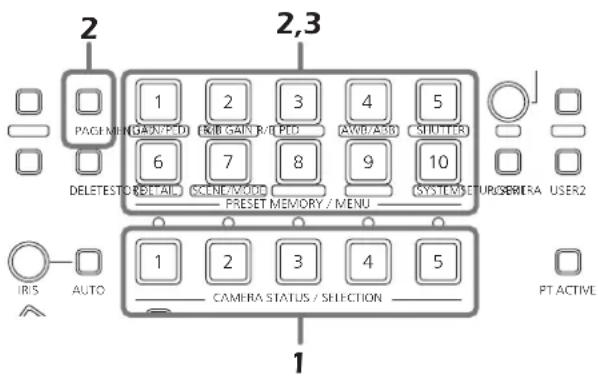
1 Press one of the CAMERA STATUS/SELECTION buttons 1 to 5 to select the remote camera to be operated. 2 Output the images to be shot by the camera to the monitor.
The camera angle to be registered is determined by operating the PAN/TILT lever and ZOOM button. If necessary, adjust the focus and iris as well.
3 Press the STORE button. 4 After pressing the PAGE button, press the PRESET MEMORY/MENU button to specify the "Page number" to be registered.
In this step, the "Page number" to be registered as the preset memory is specified.
- For details on the relationship between the "Preset number", "Page number" and "Number on the page", refer to the section entitled .
5 Hold down the PRESET MEMORY/MENU button to specify the "Number on the page".
The preset memory data is registered at the same time as the "Number on the page" is specified.
Note
When specifying the "Number on the page", hold down the PRESET MEMORY/MENU button.

To register more data, repeat steps 2 to 5.
- When specifying a different "Number on the page" on the same "Page number", it is registered by skipping step 4 and carrying out the operation in step 5 only.
- The PRESET MEMORY/MENU button corresponding to the preset number lights when preset memory data has been registered in the AW-HE50.
| Preset number | Page number | Number on the page |
| 1 to 10 | 1 | 1 to 10 |
| 11 to 20 | 2 | 1 to 10 |
| 21 to 30 | 3 | 1 to 10 |
| 31 to 40 | 4 | 1 to 10 |
| 41 to 50 | 5 | 1 to 10 |
| 51 to 60 | 6 | 1 to 10 |
| 61 to 70 | 7 | 1 to 10 |
| 71 to 80 | 8 | 1 to 10 |
| 81 to 90 | 9 | 1 to 10 |
| 91 to 100 | 10 | 1 to 10 |
Memo
Example: When specifying preset 21 Press the following buttons in the order given: PAGE button → PRESET MEMORY/MENU 3 button → PRESET MEMORY/MENU button 1.
■ Executing the preset data
1 Press one of the CAMERA STATUS/SELECTION buttons 1 to 5 to select the remote camera to be operated.
Select the remote camera which is to be pointed at the camera angle registered in the preset memory.
2 After pressing the PAGE button, press the PRESET MEMORY/MENU button to specify the registered "Page number" of the preset memory.
In this step, specify the registered "Page number" of the preset memory.
- For details on the relationship between the "Preset number", "Page number" and "Number on the page", refer to the section entitled .
3 Press the PRESET MEMORY/MENU button to specify the "Number on the page".
The preset memory data is executed at the same time as the "Number on the page" is specified.
- When the preset memory data is executed, the preset number is displayed on the right side of the top level of the LCD panel.

The preset number display is cleared when the power of the unit or remote camera has been turned off or when the camera group has been switched.
- In the case of the AW-HE50, the corresponding PRESET MEMORY/MENU button will go off, and then it will light again when preset memory data is executed. In the case of another remote camera connected serially, the corresponding PRESET MEMORY/MENU button will simply just light.
■ Deleting the preset memory data
Note
This function does not work with the AW-PH400.
1 Press one of the CAMERA STATUS/SELECTION buttons 1 to 5 to select the remote camera to be operated.
Select the remote camera whose preset memory data is to be deleted.
2 Press the DELETE button.
3 After pressing the PAGE button, press the PRESET MEMORY/MENU button to specify the "Page number" of the preset memory data to be deleted.
In this step, specify the "Page number" of the preset memory data to be deleted.
- For details on the relationship between the "Preset number", "Page number" and "Number on the page", refer to the section entitled .
4 Hold down the PRESET MEMORY/MENU button to specify the "Number on the page".
The preset memory data is deleted at the same time as the "Number on the page" is specified.
Note
When specifying the "Number on the page", hold down the PRESET MEMORY/MENU button.

Selecting the settings for a selected remote camera
The following settings and adjustments can be performed for a selected remote camera directly from this unit.
- Gain
- Pedestal • R and B gain values • R and B pedestal values
- White balance
- Black balance
- Shutter speed
- Detail
- Shooting mode selection • Color bar selection
Note
It is not possible to perform operations for those functions which are not supported by the model concerned.
For further details, refer to the "Table of menu items".
■ Setting the gain
In places which are too dark, increase the gain level; conversely, in places which are too light, reduce the gain level.
When "Auto" is selected, the light quantity is adjusted automatically.
When the gain is increased, the noise level also increases.
1 Set the MENU button to ON.
Press the MENU button to light its indicator.
2 Set the PRESET MEMORY/MENU 1 button (GAIN/PED) to ON.
When the button is pressed and its indicator lights, the [GAIN/PED] menu is displayed on the LCD panel.
3 Turn the F1 dial to select the setting.

Note
The settings will differ depending on the remote camera connected.
For further details, check the Operating Instructions of the model concerned.
■ Setting the pedestal
Perform the black level (pedestal) adjustment in order to make it easier to see the very dark parts of the images.
Adjustment in the “−” direction makes the parts closer to black; conversely, adjustment in the “+” direction makes the parts closer to white.
1 Set the MENU button to ON.
Press the MENU button to light its indicator.
2 Set the PRESET MEMORY/MENU 1 button (GAIN/PED) to ON.
When the button is pressed and its indicator lights, the [GAIN/PED] menu is displayed on the LCD panel.
3 Turn the F2 dial to select the setting.
![graph TD A["GAIN : 0 dB"] --> D["Turn the F2 dial."] B["PED : ±0"] --> D D --> C["GAIN : 0 dB"] D --> D["PED : +5"]](/content/2026/06/1328964/images/b1e48d58f947581749708f469f00c55dc3bf835926f0fe71ebd9c60a7acedddb.jpg)
Note
The settings will differ depending on the remote camera connected.
For further details, check the Operating Instructions of the model concerned.
Selecting the settings for a selected remote camera
■ Setting the white balance
The ratio between RGB (three primary colors) is adjusted so that white will be reproduced accurately.
If the white balance is off, not only will white be reproduced poorly but the color tone of the entire picture will also deteriorate.
The white balance must be adjusted when using a remote camera for the first time or when the remote camera has not been used for a prolonged period of time. It must also be adjusted when changes have been made in the lighting conditions or brightness.
The white balance can be adjusted automatically or manually (fine adjustment after automatic adjustment). In addition, preset values or the “auto tracking white adjustment (ATW)” which continues to adjust the white balance automatically all the time can be selected.
The results of white balance adjustments can be stored in memory A or memory B when “AWB A” or “AWB B” has been selected for the white balance.
Selecting the white balance mode
Follow the steps below to set the white balance mode.
1 Set the MENU button to ON.
Press the MENU button to light its indicator.
2 Set the PRESET MEMORY/MENU 4 button (AWB/ABB) to ON.
When the button is pressed and its indicator lights, the [AWB/ABB] menu is displayed on the LCD panel.
3 Turn the F1 dial to select the white balance mode.
| AWB MOD: | AWB B↓ |
| SET : | AWB↓ |
The modes which can be selected differ depending on the remote camera connected.
| Remote camera | Mode Remote camera status | |
| AW-HE50 | AWB A | The status of the white balance registered in remote camera memory A is established. |
| AWB B | The status of the white balance registered in remote camera memory B is established. | |
| ATW | In this mode, the white balance is automatically adjusted continuously all the time and automatically compensated even when the light source or color temperature has changed. | |
| AW-HE100 AW-HE870 AW-E860 AW-E750 AW-E650 AW-E350 | AWB A | The status of the white balance registered in remote camera memory A is established. |
| AWB B | The status of the white balance registered in remote camera memory B is established. | |
| 3200K | The status of the white balance which was adjusted at a brightness of 3200K is established. | |
| 5600K | The status of the white balance which was adjusted at a brightness of 5600K is established. | |
| ATW | In this mode, the white balance is automatically adjusted continuously all the time and automatically compensated even when the light source or color temperature has changed. | |
| AK-HC1500 AK-HC1800 | —— — | |
Selecting the settings for a selected remote camera
Automatically adjusting the white balance
Set the automatic adjustment if the coloring appears unnatural under certain light sources or other conditions. If the white serving as the reference can be recognized, it is possible to shoot with natural coloring.
Memo
When the white balance is adjusted, the R and B GAIN values are set to “±0”.
1 Set the MENU button to ON.
Press the MENU button to light its indicator.
2 Set the PRESET MEMORY/MENU 4 button (AWB/ABB) to ON.
When the button is pressed and its indicator lights, the [AWB/ABB] menu is displayed on the LCD panel.
3 Turn the F1 dial to select the place where the white balance is to be stored.
Select "AWB A" or "AWB B" to select the place where the white balance is stored.
| AWB MOD: AWB A↓ |
| SET : AWB↓ |
- This step need not be taken when the AK-HC1500 or AK-HC1800 is used as the remote camera.
4 Turn the F2 dial to select AWB, and press the F2 dial.
The remote camera now automatically adjusts the white balance, and registers it at the place selected in step 3.
When automatic adjustment is performed, the following details are displayed on the LCD panel.
AWB ACTIVE:
This appears while AWB is being executed.
AWB OK:
This appears for 3 seconds after AWB is completed successfully.
AWB NG:
This appears for 3 seconds after AWB is completed unsuccessfully. (AWB was executed while ATW, 3200K or 5600K was selected.)
- If it was not possible to adjust the white balance properly, change the brightness, iris, subject, light source or other aspect, and try adjusting it again.
Note
The settings will differ depending on the remote camera connected. For further details, check the Operating Instructions of the model concerned.
Selecting the settings for a selected remote camera
Manually adjusting the white balance (Setting the R and B gain values)
1 As with the automatic adjustment, fill the screen with a white subject. 2 Connect a waveform monitor or color monitor to the video output connector on the currently selected remote camera. 3 Set the MENU button to ON. Press the MENU button to light its indicator. 4 Set the PRESET MEMORY/MENU 2 button (R/BGAIN) to ON. When the button is pressed and its indicator lights, the [R/BGAIN] menu is displayed on the LCD panel. 5 Turn the F1 dial to select the R gain setting; similarly, turn the F2 dial to select the B gain setting.

Note
The settings will differ depending on the remote camera connected. For further details, check the Operating Instructions of the model concerned.
Auto tracking white adjustment (ATW)
This function provides compensation automatically so that the white balance is adjusted even when the light source or color temperature changes during shooting, so that images that appear the least odd (that is, the most natural looking) are produced.
1 Set the MENU button to ON.
Press the MENU button to light its indicator.
2 Set the PRESET MEMORY/MENU 4 button (AWB/ABB) to ON.
When the button is pressed and its indicator lights, the [AWB/ABB] menu is displayed on the LCD panel.
3 Turn the F1 dial to select ATW.

- If there is no white on the screen, it may not be possible to compensate the white balance properly. Similarly, under certain light source and color temperature conditions, it may not be possible to compensate the white balance properly.
Note
The settings will differ depending on the remote camera connected. For further details, check the Operating Instructions of the model concerned.
Selecting the settings for a selected remote camera
■ Setting the black balance
The black balance must be adjusted when using a remote camera for the first time or when the remote camera has not been used for a prolonged period of time.
It must also be adjusted when significant changes have occurred in the ambient temperature or at the change of the seasons.
If the camera is used with the same settings and under the same conditions, the black balance need not be adjusted again.
When the black balance is adjusted again, the previous memory data will be erased and replaced with the new black balance settings.
When the black balance is set, the R and B pedestal adjustment settings are returned to ±0 .
Automatically adjusting the black balance
1 Set the MENU button to ON.
Press the MENU button to light its indicator.
2 Set the PRESET MEMORY/MENU 4 button (AWB/ABB) to ON.
When the button is pressed and its indicator lights, the [AWB/ABB] menu is displayed on the LCD panel.
3 Turn the F2 dial to select ABB, and press the F2 dial.
| AWB MOD: AWB B↓ |
| SET : ABB↓ |
The remote camera now automatically adjusts the black balance.
When automatic adjustment is performed, the following details are displayed on the LCD panel.
ABB ACTIVE:
This appears while ABB is being executed.
ABB OK:
This appears for 3 seconds after ABB was completed successfully.
ABB NG:
This appears for 3 seconds after ABB was completed unsuccessfully.
Note
The settings will differ depending on the remote camera connected.
For further details, check the Operating Instructions of the model concerned.
Manually adjusting the black balance (Setting the R and B pedestal)
1 Connect a waveform monitor or color monitor to the video output connector on the currently selected remote camera.
2 Set the MENU button to ON.
Press the MENU button to light its indicator.
3 Set the PRESET MEMORY/MENU 3 button (R/BPED) to ON.
When the button is pressed and its indicator lights, the [R/BPED] menu is displayed on the LCD panel.
4 Turn the F1 dial to select the R pedestal setting; similarly, turn the F2 dial to select the B pedestal setting.
| RPED : ±0 | |
| BPED : ±0 |
Note
The settings will differ depending on the remote camera connected.
For further details, check the Operating Instructions of the model concerned.
Selecting the settings for a selected remote camera
■ Setting the shutter speed
The shutter mode and shutter speed of the remote camera can be selected.
1 Set the MENU button to ON. Press the MENU button to light its indicator.
2 Set the PRESET MEMORY/MENU 5 button (SHUTTER) to ON.
When the button is pressed and its indicator lights, the [SHUTTER] menu is displayed on the LCD panel.
3 Turn the F1 dial to select the shutter mode.
When "Step" has been selected as the shutter mode, the shutter speed can be selected by turning the F2 dial.

Notes
- The settings will differ depending on the remote camera connected. For further details, check the Operating Instructions of the model concerned.
- When a remote camera connected serially is selected and its shutter speed is set, and then a remote camera in another group is assigned to the CAMERA STATUS/SELECTION button, the shutter speed will be set to "1/100" when a menu operation is next performed.
■ Setting the detail
The image detail (image sharpness) can be adjusted.
1 Set the MENU button to ON. Press the MENU button to light its indicator. 2 Set the PRESET MEMORY/MENU 6 button (DETAIL) to ON. When the button is pressed and its indicator lights, the [DETAIL] menu is displayed on the LCD panel.
3 Turn the F1 dial to select On or Off.
4 Turn the F2 dial to select the detail level.

Note
The settings will differ depending on the remote camera connected.
For further details, check the Operating Instructions of the model concerned.
Selecting the settings for a selected remote camera
■ Setting the shooting mode
Select the shooting mode that matches the shooting conditions.
Select the mode according to the shooting conditions and your preferences.
1 Set the MENU button to ON.
Press the MENU button to light its indicator.
2 Set the PRESET MEMORY/MENU 7 button (SCENE/MODE) to ON.
When the button is pressed and its indicator lights, the [SCENE/MODE] menu is displayed on the LCD panel.
3 Turn the F1 dial to select the shooting mode.
The settings will differ depending on the remote camera connected.
For further details, check the Operating Instructions of the model concerned.
■ Specifying the color bars
The images to be output from the remote camera can be switched between the "camera images" and "color bars".
1 Set the MENU button to ON.
Press the MENU button to light its indicator.
2 Set the PRESET MEMORY/MENU 7 button (SCENE/MODE) to ON.
When the button is pressed and its indicator lights, the [SCENE/MODE] menu is displayed on the LCD panel.
3 Turn the F2 dial to select "CAM" (camera image) or "BAR" (color bars).
Operating the menu items of the selected remote camera
The menu operations of the remote cameras can be operated from the unit for the remote camera which is now selected.
The CAMERA OSD button, F1 dial and F2 dial are used to perform the operations.
When the CAMERA OSD button is held down, its indicator lights, and the on-screen menu of the selected remote camera is displayed as the output image of the remote camera.
When the button is held down again while its indicator is lighted, the menu is cleared, and the indicator goes off.

Table of operations
| Remote camera | Menu ON/OFF | Dial operation | Menu operation |
| AW-HE50 | Hold down the CAMERA OSD button. | Turn the F1 dial.(Turn it clockwise.) | Moves (downward) to an item.Changes (increments) the setting. |
| Turn the F1 dial.(Turn it counterclockwise.) | Moves (upward) to an item.Changes ( decrements) the setting. | ||
| Press the F1 dial. | Enters the setting. | ||
| AK-HC1500AK-HC1800AW-HE870 | Hold down the CAMERA OSD button. | Turn the F1 dial.(Turn it clockwise.) | Moves (downward) to an item.Changes ( decrements) the setting. |
| Turn the F1 dial.(Turn it counterclockwise.) | Moves (upward) to an item.Changes ( increments) the setting. | ||
| Press the F1 dial. | Enters the setting. | ||
| AW-E350AW-E650AW-E750AW-E860AW-HE100 | Hold down the CAMERA OSD button. | Turn the F1 dial.(Turn it clockwise.) | Moves (downward) to an item. |
| Turn the F1 dial.(Turn it counterclockwise.) | Moves (upward) to an item. | ||
| Press the F1 dial. | Enters the setting. | ||
| Turn the F2 dial.(Turn it clockwise.) | Enters the setting.Changes ( increments) the setting. | ||
| Turn the F2 dial.(Turn it counterclockwise.) | Changes ( decrements) the setting. |
Notes
- The "on" and "off" of the indicator in the CAMERA OSD button may not correspond exactly to the menu display and menu non-display when another remote camera has been selected while remote camera menu operations are being performed from the unit or when the CAMERA OSD function is set to OFF by a remote camera. In addition, the menu operations may not be performed properly.
- The operations differ depending on the remote camera model. For details on the menu items which are displayed, check the Operating Instructions of the model concerned.
Menu items can be assigned to the two USER buttons (USER1, USER2).
The target function can be activated simply by pressing the USER button (USER1 or USER2).

| Menu item Details of operation performed | ||
| SWLINK | This sets the link control between the unit and switcher. | On: EnableOff: Disable |
| BUSCONT | This is the bus switching setting. | On: EnableOff: Disable |
| FASIST | This sets the focus assist function. | On: EnableOff: Disable |
| CAMSEL | This displays icons at the bottom left of the images from the remote camera selected by the unit on the multi view display of the switcher. | On: DisplayOff: Non-display |
| TALLY_IP | This sends the tally information sent periodically by UDP from the switcher to the remote camera. | On: EnableOff: Disable |
| CAMINF | This sends the camera information of the remote camera selected to the switcher. | On: EnableOff: Disable |
| AWB | AWB is executed when the USER button, in which AWB has been assigned, is pressed.When AWB is executed successfully, the indicator of the button goes off; conversely, when it is not executed successfully, it blinks. | |
| ABB | ABB is executed when the USER button, in which ABB has been assigned, is pressed.When ABB is executed successfully, the indicator of the button goes off; conversely, when it is not executed successfully, it blinks. | |
| POWER OFF | When the USER button in which POWER OFF has been assigned is held down, the indicator of the button lights for an instant, and power OFF is requested for all the remote cameras connected. | |
■ Registering functions in the USER buttons
1 Set the MENU button to ON.
Press the MENU button to light its indicator.
2 Set the PRESET MEMORY/MENU 9 button (SETUP) to ON.
When the button is pressed and its indicator lights, the [SETUP] menu is displayed on the LCD panel.

3 Press the F1 dial.
4 Turn the F1 dial to display [USER1] or [USER2].

5 Turn the F2 dial to select the item to be assigned, and press the F2 dial.
![graph TD A["1. USER1"] -->|SWLINK↓| B["Turn the F2 dial, and then press it."] C["1. USER1"] -->|BUSCONT↓| D["End"]](/content/2026/06/1328964/images/73fbf06e4190f19c5eaeea5f722b67d71717f4c3d3b19bf72f95b647d49176a5.jpg)
Set enable (On) or disable (Off) for tally ON which provides the tally instructions to the remote camera in response to tally requests received via the GPI and network.
1 Set the MENU button to ON.
Press the MENU button to light its indicator.
2 Set PRESET MEMORY/MENU 8 button (CAMERA) to ON.
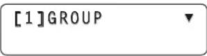
When the button is pressed and its indicator is lighted, the [CAMERA] menu is displayed on the LCD panel.
[1]GROUP

3 Turn the F1 dial to display the [TALLY] menu, and press the F1 dial.
[3] TALLY


Press the F1 dial.
- TALLY OUT
0ff↓
4 Turn the F2 dial to select On or Off, and then press the F2 dial to enter the selection.
- TALLY OUT
0ff↓

Turn the F2 dial, and then press it.
- TALLY OUT
On↓
This section describes how the unit's functions are set. The following functions can be set.
- Setting of the remote camera operations
- Registration of functions in the USER buttons
- Setting the speed at which to move to the preset memory setting position
- Setting the control items used when preset data is executed
- Controlling the peripheral devices connected to the remote cameras
- ND filter
- Wiper
- AC adapter
- Heater, fan (AW-PS300A)
- Halogen lamp
- Defroster
- Assignment of preset data when emergency interrupts occur
- Locking of button operations
The settings are established using the [SETUP] menu. First, the basic menu operations will be described.
1 Set the MENU button to ON.
Press the MENU button to light its indicator.
2 Set the PRESET MEMORY/MENU 9 button (SETUP) to ON.
When the button is pressed and its indicator lights, the [SETUP] menu is displayed on the LCD panel.
[1] USER
3 Turn the F1 dial to display the target menu item, and press the F1 dial.
For details on the [SETUP] menu items, refer to the "Table of menu items".
![graph TD A["[4"]OPERATE] --> B["Press the F1 dial."] B --> C["1.PAN DIR NORMAL↓"]](/content/2026/06/1328964/images/a37235dc46b39be598cb3cf2392e886a27aba02fb227fb58ed27525d0893c6bb.jpg)
4 Turn the F1 dial to select the target menu item.
![graph TD A["1. PAN DIR"] --> B["NORMAL↓"] C["2. TILT DIR"] --> D["NORMAL↓"] B --> E["Turn the F1 dial."] D --> E](/content/2026/06/1328964/images/1c5582b47c70224d30e8445439deb729ebacd06cdfb6b4775f446702209bb589.jpg)
5 Turn the F2 dial to select the setting. Then press the F2 dial to change the setting.
![graph TD A["2. TILT DIR"] --> B["NORMAL↓"] B --> C["Turn the F2 dial, and then press it."] D["2. TILT DIR"] --> E["REVERSE↓"]](/content/2026/06/1328964/images/f4378ea290b8d279e12c803ddba3fd8cd85b6dcbf98e139e5a96c5bb1b62a246.jpg)
■ Setting the remote camera operations
Set these operations by selecting the [SETUP] menu followed by the [OPERATE] menu.
[4]OPERATE
●Setting the pan, tilt, zoom and focus operation directions
Set the directions in which the remote camera is to move when the panning, tilting, zooming or focusing operation has been initiated from the unit.
Setting the panning direction
From the [SETUP] menu, select [OPERATE] and display [PAN DIR]. Then select either "NORMAL" or "REVERSE".
- PAN DIR
NORMAL↓
This sets the operation of the remote camera in the horizontal direction in response to the horizontal manipulation of the PAN/TILT lever.
When "NORMAL" is selected as the setting, the remote camera will move to the left when the PAN/TILT lever is leaned toward the left and, conversely, it will move to the right when the lever is leaned toward the right.
When "REVERSE" is selected, the remote camera will move in the opposite directions.
Setting the tilting direction
From the [SETUP] menu, select [OPERATE] and display [TILT DIR]. Then select either "NORMAL" or "REVERSE".
- TILT DIR
NORMAL↓
This sets the operation of the remote camera in the vertical direction in response to the vertical manipulation of the PAN/TILT lever.
When "NORMAL" is selected as the setting, the remote camera will move upward when the PAN/TILT lever is leaned away from you and, conversely, it will move downward when the lever is leaned toward you.
When "REVERSE" is selected, the remote camera will move in the opposite directions.
Setting the zooming direction
From the [SETUP] menu, select [OPERATE] and display [ZOOM DIR]. Then select either "NORMAL" or "REVERSE".
3.ZOOM DIR NORMAL↓
This sets the zooming operation of the lens in response to the operation of the ZOOM button.
When "NORMAL" is selected as the setting, the lens zooms toward the tele end when the TELE side of the ZOOM button is pressed and, conversely, it will zoom toward the wide end when the WIDE side is pressed.
When "REVERSE" is selected, the lens will move in the opposite directions.
Setting the focusing direction
From the [SETUP] menu, select [OPERATE] and display [FOCUS DIR]. Then select either "NORMAL" or "REVERSE".
- FOCUS DIR NORMAL↓
This sets the focusing operation of the lens in response to the operation of the FOCUS/PUSH OTAF dial.
When "NORMAL" is selected as the setting, the lens focus moves toward the far end when the dial is turned clockwise and, conversely, it will move toward the near end when the dial is turned counterclockwise.
When "REVERSE" is selected, the lens will move in the opposite directions.
●Settings when the remote camera moves horizontally or vertically during tele shooting
During tele shooting, the remote camera's pan/tilt operation are slowed down to make positioning easier.
Note
This function takes effect when the unit is connected to the AW-HE50. It does not work with any other models.
From the [SETUP] menu, select [OPERATE] and display [SPEED WITH Z]. Then set the movement speed.
5.SPEED WITH Z ♦ Off↓
On: The speed at which the remote camera moves is reduced.
Off: The remote camera moves at the normal speed.
- Selecting the control items (pan, tilt, zoom and focus)
Select the control items for the currently selected remote camera.
From the [SETUP] menu, select [OPERATE] and display [SPEED TARGET]. Then select the control item.
6.SPEED TARGET ◆ P/T/Z/F↓
P/T/Z/F:
The operation speed setting takes effect for panning, tilting, zooming, and focusing.
P/T:
The operation speed setting takes effect for panning and tilting.
●Switching from focus control to iris control or vice versa
It is possible to switch the control, which is implemented by dial and button operations, from focus control to iris control (or vice versa).

From the [SETUP] menu, select [OPERATE] and display [FOCUS/IRIS]. Then select either "STANDARD" or "EXCHANGE".
- FOCUS/IRIS STANDARD↓
When "EXCHANGE" is selected as the setting, focus control and iris control are switched.
When "STANDARD" is selected, the original control is restored.
●Setting the PAN/TILT lever inclination and speed
The correlation between angle and operating speed when the PAN/TILT lever is inclined can be adjusted.
From the [SETUP] menu, select [OPERATE] and display [P/T CURV]. Then set the correlation between the lever angle and its operating speed.
8.P/T CURV ▲ 1↓
- The higher the value selected, the slower the operating speed.

■ Setting the speed at which to move to the position set by the preset memory
The speed at which to move to the position where the remote camera has been set to be in the preset memory when the preset operation is conducted can be set.
From the [SETUP] menu, select [PRESET] and display [DIAG SPEED]. Then set the speed.
The higher the setting, the faster the operating speed.
- DIAG SPEED ▼ 1↓
■ Setting the operations to be performed when a preset operation is executed
The operations which the remote camera is to perform when the preset operation is conducted can be set.
From the [SETUP] menu, select [PRESET] and display [SCOPE]. Then set the operations to be performed.
2.SCOPE MODE A↓
The operations that the camera performs when a preset operation is executed differ depending on the mode selected.
| Mode Operations performed |
| MODE A Pan, tilt, zoom, focus, iris, gain, white balance |
| MODE B Pan, tilt, zoom, focus, iris |
| MODE C Pan, tilt, zoom |
Note
This function takes effect when the unit is connected to the AW-HE50. It does not work with any other models.
■ Returning the remote cameras to their home position
The remote cameras connected can be returned to their home position.
From the [SETUP] menu, select [PRESET] and display [HOME POSITION]. Then press the F2 dial.
- HOME POSITION▲ SET↓
■ Adjusting the panning, tilting, zooming and focusing speed
The speed is adjusted uniformly for the panning, tilting, zooming and focusing together.
When the PTZ/FOCUS SPEED dial is turned clockwise, the speed is increased; conversely, when it is turned counterclockwise, it is reduced.

From the [SETUP] menu, select [OPERATE] and display [SPEED TARGET]. If P/T is selected, the speed adjustment is confined to panning and tilting only.
In this case, the zooming and focusing speed is fixed to the speed which was set immediately before P/T was selected.
■ Setting the movement range of the remote camera (limiter function)
This unit has a limiter function which is a function that limits the movement range of the remote cameras.
There are four limiter positions: the upper, lower, left and right limits of the movement range.
When the AW-HE50 is used:
Depending on the nature of the AW-HE50's installation location, there may be some subjects inside its movement range which it is not desirable or necessary to shoot.
In cases like this, the shooting range of the AW-HE50 can be limited by setting limiters in front of those subjects which are not to be shot.
When any other remote camera is used:
Depending on the installation position, there may be an obstruction in the movement range, and the remote cameras may come into contact with this obstruction.
If the remote cameras come into contact with an obstruction, trouble or accidents may result.
In cases like this, a limiter can be set in front of the obstruction to prevent contact.
●Setting the upper limit
From the [SETUP] menu, select [PTZ ADJ] and display [LIMIT UP]. Then set the upper limit.
The setting that is displayed differs between the AW-HE50 and other remote cameras.
Display that appears with the AW-HE50
The current setting status is displayed in the LIMIT UP item.
![graph TD A["2. LIMIT UP"] -->|Off ↓| B["Turn the F2 dial, it."] C["2. LIMIT UP"] -->|On ↓| B](/content/2026/06/1328964/images/20c46efd1b7dc76aa9e0d45e03c8d89ed4200462e8b7ca9e04334274ba6caa18.jpg)
Display that appears with other remote cameras
The setting status is displayed after the completion of the setting in the LIMIT UP item.
![graph TD A["2. LIMIT UP"] --> B["EXEC ↓"] C["2. LIMIT UP"] --> D["LIMIT ON ↓"] E["Press the F2 dial."] --> C](/content/2026/06/1328964/images/b4c6f6c00f0486ccab12efbe501f42fc9f6ea1c13e7936972792783e18b0949a.jpg)
●Setting the lower limit
From the [SETUP] menu, select [PTZ ADJ] and display [LIMIT DOWN]. Then set the lower limit.
The setting that is displayed differs between the AW-HE50 and other remote cameras.
Display that appears with the AW-HE50
The current setting status is displayed in the LIMIT DOWN item.
![graph TD A["3. LIMIT DOWN"] -->|Off↓| B["Turn the F2 dial, and then press it."] C["3. LIMIT DOWN"] -->|On↓| D["Turn the F2 dial, and then press it."]](/content/2026/06/1328964/images/d64d74f03727eb0afd5c3dbd505f17383f77243c81e9b9ce485843d063111201.jpg)
Display that appears with other remote cameras
The setting status is displayed after the completion of the setting in the LIMIT DOWN item.
![graph TD A["3. LIMIT DOWN"] --> B["EXEC ↓"] C["3. LIMIT DOWN"] --> D["LIMIT ON ↓"] E["Press the F2 dial."] --> C](/content/2026/06/1328964/images/9c7976eb19f95d1c3354637a4bb7aba348d1603fedabf9a4dc85f5939f5675bc.jpg)
●Setting the left limit
From the [SETUP] menu, select [PTZ ADJ] and display [LIMIT LEFT]. Then set the left limit.
The setting that is displayed differs between the AW-HE50 and other remote cameras.
Display that appears with the AW-HE50
The current setting status is displayed in the LIMIT LEFT item.
![graph TD A["4. LIMIT LEFT"] -->|Off ↓| B["Turn the F2 dial, it."] C["4. LIMIT LEFT"] -->|On ↓| D["End"]](/content/2026/06/1328964/images/813fb300fc809dd2d4e93e4e29efde0cbe46bc5c9803eec28c56d6197599486b.jpg)
Display that appears with other remote cameras
The setting status is displayed after the completion of the setting in the LIMIT LEFT item.
![graph TD A["4. LIMIT LEFT"] -->|EXEC↓| B["Press the F2 dial."] C["4. LIMIT LEFT"] -->|LIMIT ON↓| D["End"]](/content/2026/06/1328964/images/504e43a99496cb9ceed98a26c6d3bca932b33bca082c92a350c5ef3b5599bbd4.jpg)
●Setting the right limit
From the [SETUP] menu, select [PTZ ADJ] and display [LIMIT RIGHT]. Then set the right limit.
The setting that is displayed differs between the AW-HE50 and other remote cameras.
Display that appears with the AW-HE50
The current setting status is displayed in the LIMIT RIGHT item.
![graph TD A["5. LIMIT RIGHT ▲<br>Off ↓"] --> B["Turn the F2 dial, and then press it."] C["5. LIMIT RIGHT ▲<br>On ↓"] --> B](/content/2026/06/1328964/images/a54acb70d63b954cb3eef357e6701f33e71a2fb2839775368f6955edfe08063e.jpg)
Display that appears with other remote cameras
The setting status is displayed after the completion of the setting in the LIMIT RIGHT item.
![graph TD A["5. LIMIT RIGHT ▲ EXEC ↓"] --> B["Press the F2 dial."] C["5. LIMIT RIGHT ▲ LIMIT ON ↓"] --> B](/content/2026/06/1328964/images/16eca45b4869a6a65d8c2d0991b44717c43d6db3f30a725a27d134dccd664421.jpg)
■ Controlling the peripheral devices connected to the remote cameras
When any of the peripheral devices listed below are connected to the remote cameras, they can be controlled.
- ND filter
- Wiper
- AC adapter
- Heater, fan
(AW-PS300A)
- Halogen lamp
- Defroster
Control is exercised using the FUNCTION item of the [SETUP] menu.
[6]FUNCTION

Controlling an ND filter
This item is used to control the ND filter when using a lens with an ND filter function on the currently selected remote camera.
From the [SETUP] menu, select [FUNCTION] and display [ND FILTER]. Then select ND filter control.
- ND FILTER
0ff↓
Controlling an AC adapter (AW-PS300A)
This item is used to control shorting and releasing of the OPTION SW CONTROL OUT connector when using an AC adapter (AW-PS300A) for the currently selected remote camera.
From the [SETUP] menu, select [FUNCTION] and display [OPTION]. Then select shorting or releasing.
- OPTION
0ff↓
Controlling a defroster
This item is used to control a defroster when using a remote camera (AW-PH650 + camera) equipped with a defroster function as the currently selected remote camera. From the [SETUP] menu, select [FUNCTION] and display [DEFROSTER]. Then select defroster On or Off.
3.DEFROSTER
0ff↓
Controlling a wiper
This item is used to control a wiper when using a remote camera (AW-PH650 + camera) equipped with a wiper function as the currently selected remote camera.
From the [SETUP] menu, select [FUNCTION] and display [WIPER]. Then select wiper On or Off.
4.WIPER

0ff↓
Controlling a heater/fan
This item is used to control a heater/fan when using a remote camera (AW-PH650 + camera) equipped with a heater or fan function as the currently selected remote camera.
From the [SETUP] menu, select [FUNCTION] and display [HEATER/FAN]. Then select heater/fan On or Off.
- HEATER/FAN

Off↓
Controlling a halogen lamp
This item is used to control the lighting (On) and extinguishing (Off) of the halogen lamp when a halogen lamp has been connected to the currently selected remote camera.
From the [SETUP] menu, select [FUNCTION] and display [LAMP]. Then select halogen lamp lighting (On) and extinguishing (Off).
- LAMP

Off↓
■ Adjusting the minimum lens zoom start speed
This adjustment ensures that the lens zoom will start moving smoothly in line with the inclination of the ZOOM button when operating the lens zoom using the ZOOM button.
From the [SETUP] menu, select [PTZ ADJ] and display [Z MIN SPEED]. Then turn the F2 dial to set the compensation amount.
1.Z MIN SPEED ◆ Off↓
The lowest compensation amount is "1", and the highest is "8".
No compensation is provided at the "Off" setting. While observing the images on a monitor, hold down the ZOOM button slowly, and check whether the lens zoom starts moving smoothly.
■ Exercising external control over the preset memory data
Preset numbers can be assigned to execute presets for the selected remote cameras when signals have been input to the TALLY/GPI input/output connector.
The presets are assigned using the GPI item on the [SETUP] menu.
[8]GPI
Setting the preset numbers
From the [SETUP] menu, select [GPI], and display [PRESET CTL1], [PRESET CTL2] or [PRESET CTL3]. Then set the camera number and preset number.
1.PRESET CTL1 CAM100↓ PRE100↓
Any camera number from "CAM1" to "CAM100" or "ALL" can be selected.
- If "ALL" has been selected, it will not be possible to execute the preset operations for any remote cameras which have been set to "NoAsign" as the connection setting. Refer to "Settings for connection with the remote cameras" (Operating Instructions).
The preset number setting can be established for each GPI input.
• Input1: PRESET CTL1 • Input2: PRESET CTL2 • Input3: PRESET CTL3
■ Locking the button operations
This disables the operation of the CAMERA OSD button and PRESET MEMORY/MENU buttons (1 to 7).
The button operations are locked using the MENU CTL item of the [SETUP] menu.
[10]MENU CTL ▲
Setting button operation enable or disable
From the [SETUP] menu, select [MENU CTL] and display [MENU CONTROL]. Then set button operation enable or disable.
- MENU CONTROL ENABLE↓
When "DISABLE" is selected, the following button operations are disabled:
• CAMERA OSD button • PRESET MEMORY/MENU 1 to 7 buttons (However, these buttons can still be used to execute preset settings.)
■ Adjusting the LCD panel backlight
The backlight of the LCD panel can be adjusted.
Make this adjustment using the LCD BL item on the [SETUP] menu.
[9]LCD BL
Adjusting the backlight
From the [SETUP] menu, select [LCD BL] and display [BACKLIGHT]. Then set whether the backlight is to be turned on or off.
- BACKLIGHT Off↓
This setting is used to link the unit with an optional switcher (AW-HS50).
To link the unit with the switcher, the following settings must be established in the unit.
IP address (switcher) setting
[SYSTEM] menu → [SW IP ADR]
Assign information setting
[SYSTEM] menu → [SW CTL]
Link connection setting
[SETUP] menu → [SW LINK] → [SWLINK]
Settings at the switcher
For details on the settings selected at the switcher, refer to the Operating Instructions of the switcher.
■ Switcher network settings
1 Set the MENU button to ON.
Press the MENU button to light its indicator.
2 Set PRESET MEMORY/MENU 10 button (SYSTEM) to ON.
When the button is pressed and its indicator is lighted, the [SYSTEM] menu is displayed on the LCD panel.
[1] CAMERA CTL ▼
3 Turn the F1 dial, display the SW IP ADR menu, and press the F1 dial.
![[9] SW IP ADR Press the F1 dial. 1.IP:SW 192↓168.000.008](/content/2026/06/1328964/images/e5c9b4124c07137f1849a3bb959624db947db2584c660c6ba334175f933e8a24.jpg)
4 Turn the F2 dial, select the IP address, and then press the F2 dial to enter the selection.
Set the IP address which has been set in the switcher.

Input the IP address in four blocks of numerals.
When input advances to the last block and the F2 dial is pressed, the IP address is entered.

5 Press the EXIT button.
Operation now returns to the SW IP ADR menu.

6 Turn the F1 dial to display the SW CTL menu, and press the F1 dial.
![graph TD A["[3"]SW CTL] --> B["Press the F1 dial."] B --> C["1.SW"] C --> D["NoAsign↓"]](/content/2026/06/1328964/images/ee521d2b509cbc5b9cfdfec3fe19a4e5fa40e884065376eb683554642491401a.jpg)
7 Turn the F2 dial to select "Network", and then press the F2 dial to enter the selection.

■ Link setting
1 Set the MENU button to ON.
Press the MENU button to light its indicator.
2 Set PRESET MEMORY/MENU 9 button (SETUP) to ON.
When the button is pressed and its indicator is lighted, the [SETUP] menu is displayed on the LCD panel.
[1] USER

3 Turn the F1 dial, display the SW LINK menu, and press the F1 dial.
[2]SW LINK


Press the F1 dial.
1.SWLINK

Off
4 Turn the F2 dial to select On, and then press the F2 dial to change the setting.
1.SWLINK

On
When “On” is selected as the item setting, the settings mentioned below take effect, and the link with the switcher is established.
Control can also be exercised by assigning this setting to a USER button.
Setting the functions when the unit is linked with the switcher
Set the various functions to be used when the unit is linked with the switcher.
■ Setting the image output and image input
This setting establishes the correlation between the image output (remote camera) and image input (switcher). By establishing the setting, the switcher is notified if a remote camera which has been set is selected when the remote cameras have been selected by the unit.
1 Set the MENU button to ON.
Press the MENU button to light its indicator.
2 Set PRESET MEMORY/MENU 10 button (SYSTEM) to ON.
When the button is pressed and its indicator is lighted, the [SYSTEM] menu is displayed on the LCD panel.
[1] CAMERA CTL ▼
3 Turn the F1 dial to display the SW ASSIGN menu, and press the F1 dial.
![graph TD A["[4"]SW ASSIGN] --> B["Press the F1 dial."] B --> C["1. INPUT1 ▼ CAM1↓"]](/content/2026/06/1328964/images/e85b7729b55ddad21847a92213b258ed56dff4e07773c4a4531a2a42e559a25b.jpg)
4 Turn the F1 dial to select the input line of the switcher.
![graph TD A["1. INPUT1"] --> B["2. INPUT2"] C["CAM1↓"] --> B B --> D["♦ CAM1↓"] style A fill:#f9f,stroke:#333 style B fill:#ccf,stroke:#333](/content/2026/06/1328964/images/17f109d50b8da6edd68ec717e035efa30664d06dc45150623b5e8789354919eb.jpg)
5 Turn the F2 dial to select the remote camera, and then press the F2 dial to enter the selection.
![graph TD A["2. INPUT2"] --> B["CAM1↓"] C["2. INPUT2"] --> D["CAM2↓"] E["Turn the F2 dial, and then press it."] --> C](/content/2026/06/1328964/images/fdb21609f9c93246c5271fdf6ae87b0b05f196da69e24f532471a460af93bee2.jpg)
The switcher has five input lines: INPUT1 to INPUT5. Take the above steps to set the remote cameras for the input lines, and then operate the remote cameras.
- Select "NoAsign" if the switcher is not to be notified of the correlation setting when the remote cameras have been selected.
Setting the functions when the unit is linked with the switcher
■ Switcher settings
A setting for controlling the switcher linked with the unit is available.
It is established using the [SETUP] menu.
Before taking the steps described here, the steps for
"Switcher network settings" and "Setting the image output and image input" must be taken.
First, the basic menu operations will be described.
1 Set the MENU button to ON.
Press the MENU button to light its indicator.
2 Set PRESET MEMORY/MENU 9 button (SETUP) to ON.
When the button is pressed and its indicator is lit, the [SETUP] menu is displayed on the LCD panel.
[1] USER

3 Turn the F1 dial to display the SW LINK menu, and press the F1 dial.
![graph TD A["[2"]SW LINK] --> B["Press the F1 dial."] C["1.SWLINK"] --> D["Off"]](/content/2026/06/1328964/images/aa8b1954518b9f03289e8b9446fb41933358ec30f27f46badd2f3878e9e15cc6.jpg)
4 Turn the F1 dial to select the menu item to be set.
![graph TD A["1.SWLINK"] -->|Off↓| B["Turn the F1 dial."] C["2.BUSCONT"] -->|Off↓| D["Turn the F1 dial."]](/content/2026/06/1328964/images/e4ade479ee7c4a03d939a1e7ec4845f951e0f334500492c36e02ee794234d9db.jpg)
5 Turn the F2 dial to select the settings, and then press the F2 dial to change the setting.
![graph TD A["2. BUSCONT"] -->|Turn the F2 dial, and then press it.| B["2. BUSCONT"] B -->|Press press it.| A A -->|Off ↓| C["↓"] B -->|On ↓| D["↓"]](/content/2026/06/1328964/images/59ce48486cf81b4c71206a3df2145b267b7fa6550689e9e20d8f918d66c55a85.jpg)
Bus switching
From the [SETUP] menu, select [SW LINK] and display [BUSCONT]. Then select On or Off.

When “On” is selected as the item setting, the materials set using the BUS item (described later) are sent from the remote camera to the switcher when the remote camera has been selected using one of the unit's CAMERA STATUS/SELECTION buttons.
Control can also be exercised by assigning this setting to a USER button.
Setting the functions when the unit is linked with the switcher
Bus setting
From the [SETUP] menu, select [SW LINK] and display [BUS]. Then set the material (AUX, PVW, PinP or KEY) to be sent to the switcher.
3.BUS

AUX↓
The materials set using this item are sent from the remote camera to the switcher when the remote camera has been selected using one of the unit's CAMERA STATUS/SELECTION buttons.
Control can also be exercised by assigning this setting to a USER button (BUSCONT).
Focus assist setting
From the [SETUP] menu, select [SW LINK] and display [FASIST]. Then set On or Off.
4.FASIST

0ff↓
When “On” is selected as this item’s setting, the images of the AUX bus output from the switcher will be switched to the images of the remote camera selected by the unit.
Conversely, when "Off" is selected, the switcher will switch the images of the AUX bus output from the switcher to the images of its multi view display.
Camera information setting
From the [SETUP] menu, select [SW LINK] and display [CAMSEL]. Then set On or Off.
- CAMSEL

0ff↓
When "On" is selected as the item setting, an icon appears at the bottom left of the image of the remote camera selected by the unit on the switcher's multi view display. When a remote camera has been selected, its information is sent from the unit to the switcher.
Setting the functions when the unit is linked with the switcher
OA tally setting
From the [SETUP] menu, select [SW LINK] and display [TALLY_IP]. Then set it to On or Off.

When “On” is selected as the item setting, the unit receives the tally information (tally ON/OFF) sent periodically from the switcher through the network, and it sends the ON or OFF instruction to the remote cameras in which changes have occurred.
[Concerning the tally information transferred through the network]
After receiving the tally information (Input1 to Input5) from the switcher through the network, the unit sends the ON or OFF instruction to the remote cameras.
Based on the relationship between the image output (remote camera) and image input (switcher) which have been set using the unit's menu, the remote camera to which the tally instruction is sent in response to the tally information received from the switcher is identified, the tally indicator of that remote camera is lighted in red, and the tally ON instruction is sent to the remote camera.
The Tally ON instruction is also sent to the remote cameras which are not in the selected camera group.
![graph TD A["Input"] --> B["AW-RP50"] B --> C["AW-HS50"] C --> D["TALLY CAM"] D --> E["Group 1"] E --> F["Group 2"] F --> G["GPI Input"] H["IP RP50CAMNo"] --> I["Input1 CAM1"] H --> J["Input2 CAM2"] H --> K["Input3 CAM3"] H --> L["Input4 CAM4"] H --> M["Input5 CAM5"]](/content/2026/06/1328964/images/cf7b13d0628dbe5e80e8736e09e4d9824f9ce5ab585f9c4bc8422315f46a35e2.jpg)
In response to inputs 1 to 5 from GPI Input, tally indicators CAM1 to CAM5 are lighted in red, and the tally ON instruction is sent to the remote cameras concerned.
Only CAM1 to CAM5 serve as the GPI Input tally.
This means that when a camera group other than No.1 is selected, the tally indicators will go off.
The following tally-related settings can be established using the menu.
- Enabling/disabling the tally information instructions sent over the network
If only the tally information from GPI is to be enabled, from the [SETUP] menu select [SW LINK], set [TALLY_IP] to Off, and disable the tally information instructions sent over the network.
- Enabling/disabling the tally ON instructions sent to the remote cameras
From the [CAMERA] menu, select [TALLY] and display [TALLY OUT]. Then set enable or disable for the tally ON instructions to be sent to the remote cameras in response to the tally requests from the GPI and over the network.
PAN/TILT lever control setting
This setting makes it possible to use the unit's PAN/TILT lever as the switcher's control lever.
From the [SETUP] menu, select [SW LINK] and display [P/T LEVER]. Then set Self or SW.

When “Self” has been selected as the setting, the unit's PAN/TILT lever is used as the lever for operating the pan and tilt functions of the remote cameras.
When "SW" has been selected, the following information is sent to the switcher.
PAN/TILT lever: X, Y
ZOOM button: Size
Setting the functions when the unit is linked with the switcher
■ Setting for the information to be displayed on the OSD
This setting displays the remote camera information on the OSD of the monitor which is connected to the switcher to be linked to the unit.
The setting is established using the [SETUP] menu. Before taking the steps here, the steps for "Switcher network settings" and "Setting the image output and image input" described earlier must be taken.
First, the basic menu operations will be described.
1 Set the MENU button to ON.
Press the MENU button to light its indicator.
2 Set PRESET MEMORY/MENU 9 button (SETUP) to ON.
When the button is pressed and its indicator is lighted, the [SETUP] menu is displayed on the LCD panel.

3 Turn the F1 dial to display the SW DISP menu, and press the F1 dial.
![graph TD A["[3"]SW DISP] --> B["Press the F1 dial."] B --> C["1.CAMINF"] C --> D["Off↓"]](/content/2026/06/1328964/images/b6f81420c187c551032f89db81b70b64a9d6798667400af435017ca03b85d4e7.jpg)
4 Turn the F1 dial to select the menu item to be set.
![graph TD A["1. CAMINF"] -->|Off↓| B["Turn the F1 dial."] C["2. FORMAT"] -->|Off↓| D["Turn the F1 dial."]](/content/2026/06/1328964/images/6a93200ebcee098c6666ec204c8b304160c45f8d0ff8cc7db69cd248ebeeb220.jpg)
5 Turn the F2 dial to select On or Off, and then press the F2 dial to enter the selection.
![graph TD A["2. FORMAT"] -->|Off ↓| B["Turn the F2 dial, and then press it."] C["2. FORMAT"] -->|On ↓| D["Turn the F2 dial, and then press it."]](/content/2026/06/1328964/images/3e9cf003e3ce1763c520d5fda646ce21b396f99e5e07a150d71d9e108ddb7f24.jpg)
●Setting all the information displays together
From the [SETUP] menu, select [SW DISP] and display [CAMINF]. Then set On or Off.

When "On" is selected as the item setting, the information of the remote cameras set in "Setting the image output and image input" is sent to the switcher.
Control can also be exercised by assigning this setting to a USER button.
① Video format (This is left blank when the video format of the remote camera cannot be recognized.) ② Scene file name (shooting mode) ③ Filter information ④ Remote camera alarm information ⑤ Shutter information (ON/OFF, shutter value) ⑥ Gain value ⑦ Iris value ⑧ Remote camera name (displayed with up to 10 characters)

Setting the functions when the unit is linked with the switcher
- Setting each information item to be displayed
Video format
From the [SETUP] menu, select [SW DISP] and display [FORMAT]. Then set On or Off.
- FORMAT
Off↓
Remote camera name
From the [SETUP] menu, select [SW DISP] and display [CAMNAME]. Then set On or Off.
3.CAMNAME
0ff↓
Scene file name
From the [SETUP] menu, select [SW DISP] and display [SCENE]. Then set On or Off.
- SCENE
0ff↓
Gain value
From the [SETUP] menu, select [SW DISP] and display [GAIN]. Then set On or Off.
- GAIN
0ff↓
Shutter information
From the [SETUP] menu, select [SW DISP] and display [SHUTTER]. Then set On or Off.
6.SHUTTER
Iris value
From the [SETUP] menu, select [SW DISP] and display [IRIS]. Then set On or Off.
- IRIS
Off↓
Filter information
From the [SETUP] menu, select [SW DISP] and display [FILTER]. Then set On or Off.
- FILTER
Off↓
Remote camera alarm information
From the [SETUP] menu, select [SW DISP] and display [ALARM]. Then set On or Off.
- ALARM
Checking the equipment alarm information
It is possible to check the alarm statuses of the unit and the remote cameras assigned to the CAMERA STATUS/SELECTION buttons.
1 Set the MENU button to ON.
Press the MENU button to light its indicator.
2 Set PRESET MEMORY/MENU 10 button (SYSTEM) to ON.
When the button is pressed and its indicator is lighted, the [SYSTEM] menu is displayed on the LCD panel.
[1] CAMERA CTL
3 Turn the F1 dial to display the ALARM menu, and press the F1 dial.
![graph TD A["[10"]ALARM] --> B["Press the F1 dial."] B --> C["1.POWER\nNo ALARM↓"]](/content/2026/06/1328964/images/b41334dde3a4bf8a5a6b9edc23ca269ec1c5d1a4ed6653c659b40a1c418693b2.jpg)
4 Turn the F1 dial to select the unit (POWER) or remote camera item (CAM1 to CAM100).
The alarm status is displayed underneath.
![graph TD A["1. POWER"] --> B["No ALARM↓"] B --> C["Turn the F2 dial."] D["2. CAM1"] --> E["FAN ALM↓"]](/content/2026/06/1328964/images/8250b9a3f9d975f4380198f1969feb852a57c96798fe2af3e3029f811fd2741b.jpg)
[Select POWER]
The unit's power supply alarm can be checked.
No ALARM:
When the power supply is trouble-free.
ALARM:
When trouble has occurred in the power supply.
[Select CAM1 to CAM100]
The alarm statuses of the remote cameras currently assigned to the CAMERA STATUS/SELECTION buttons are displayed.
No ALARM:
Trouble-free.
FAN ALM:
Trouble has occurred in the cooling fan.
P/T ALM:
Trouble has occurred in the pan/tilt operation.
FAN ALM+P/T ALM:
Trouble has occurred in the cooling fan and pan/tilt operation.
Note
When an alarm has occurred, stop operation immediately, and be absolutely sure to contact your dealer.
Continued use may cause the unit to malfunction.
Returning the unit to its factory status
The unit's settings can be returned to the factory statuses. Two methods can be used: One method returns all the settings to the factory statuses, and the other returns only the [SETUP] menu settings to the factory statuses.
1 Set the MENU button to ON.
Press the MENU button to light its indicator.
2 Set PRESET MEMORY/MENU 10 button (SYSTEM) to ON.
When the button is pressed and its indicator is lighted, the [SYSTEM] menu is displayed on the LCD panel.

3 Turn the F1 dial to display the INITIALIZE menu, and press the F1 dial.
![graph TD A["[11"] INITIALIZE] --> B["Press the F1 dial."] B --> C["1. INITIALIZE ALL!"]](/content/2026/06/1328964/images/d0ff47c0171d55e5d14c7431f76328d46db1087729472824c20c5524735de881.jpg)
4 Turn the F2 dial to select the initializing mode.
![graph TD A["1. INITIALIZE ALL↓"] --> B["Turn the F2 dial."] C["1. INITIALIZE SETUP↓"] --> B](/content/2026/06/1328964/images/c5b596ed02df669845f9866d1c039cd1c7b2ac1557d5b5e5dd6f11853d5af08d.jpg)
ALL:
The settings controlled by the unit are returned to the factory statuses.
SETUP:
Only the settings on the menus below are returned to the factory statuses.
| [CAMERA] menu | |
| [2]POWER | |
| [3]TALLY | |
| [SETUP] menu | |
| [1]USER | |
| [2]SW LINK | |
| [3]SW DISP | |
| [4]OPERATE | |
| [5]PRESET | |
| [8]GPI | |
| [9]LCD BL | |
| [10]MENU CTL | |
5 Press the F2 dial to initialize the settings.
TALLY/GPI
TALLY IN 1 to TALLY IN 5 are contact input ports which are used to light the unit's tally indicators (above the CAMERA STATUS/SELECTION buttons).
The tally lamps light with contact input. GPI IN 1 to GPI IN 4 are contact input ports used to control the unit from an external source. GPI OUT 1 to GPI OUT 4 are open output ports used to output statuses to an external source. (D-sub 15-pin, female, inch thread)
| Pin No. Signal Description of signal Operation | ||||
| 1 TALLY IN 1 CAM1 tally input | Contact input | |||
| 9 TALLY IN 2 CAM2 tally input | ||||
| 2 TALLY IN 3 CAM3 tally input | ||||
| 10 TALLY IN 4 CAM4 tally input | ||||
| 3 TALLY IN 5 CAM5 tally input | ||||
| 11 GND Ground | ||||
| 4 GPI IN 1 Preset input 1 | Contact input | |||
| 12 GPI IN 2 Preset input 2 | ||||
| 5 GPI IN 3 Preset input 3 | ||||
| 13 GPI IN 4 Panel lock | ||||
| 6 GPI OUT 1 | Remote camera selection 0 * | Open collector output | ||
| 14 GPI OUT 2 | Remote camera selection 1 * | |||
| 7 GPI OUT 3 | Remote camera selection 2 * | |||
| 15 GPI OUT 4 Alarm | ||||
| 8 NC | Not used | |||
Example of GPI OUT connections
Ensure that the conditions given below are satisfied.
Dielectric strength: Max. DC 24 V
Current: Max. 50 mA

Example of TALLY IN and GPI IN connections
Provide contact inputs.

*: The selection statuses (CAMERA STATUS/SELECTION buttons 1 to 5) of the remote cameras can be monitored at GPI OUT 1 to GPI OUT 3.
| CAMERA STATUS/SELECTION button | Remote camera selection 0 (GPI OUT 1) | Remote camera selection 1 (GPI OUT 2) | Remote camera selection 2 (GPI OUT 3) |
| 1 | On | Off | Off |
| 2 | Off | On | Off |
| 3 | On | On | Off |
| 4 | Off | Off | On |
| 5 | On | Off | On |
The "Setup Software" is an application that enables the same functions as the unit's automatic IP settings to be executed from the host computer.
This is used to set the network environment for operating the remote camera using the host computer.
It can save the setting data files in the host computer, and it can load the saved files and reflect them in the network environment.
For details, refer to the sections that follow.
Notes
When the settings are to be selected at the host computer using the "Setup Software":
- Do not perform the operation at the unit.
- Do not start up the "Setup Software" on any other computer in the same network.
- Do not use the "Easy IP Setup Software" that is provided with the AW-HE50.
■ Installing the software
This section describes how to install the Setup Software.
- Insert the CD-ROM provided with the unit into the CD-ROM drive of the host computer where the software application is to be installed.
- Copy the entire folder containing "Setup Software" from the CD-ROM onto the hard disk drive of the host computer.
- Double-click on "RP50Tool.exe" in the "Setup Software" folder that was copied to start the Setup Software.
■ IP settings
On the "Setting" tab screen, set the IP addresses of the remote cameras and switcher.

● Displaying the "Setting" tab

① List box
The IP address of the AW-RP50 connected to the network is displayed here.
The information of the network environment established by the AW-RP50 selected here is displayed on the "Setting" tab.
② Type
The units connected to the selected AW-RP50 are displayed in this column.
CAMERA: Remote camera
SW: Switcher
③ Group
The numbers of the groups of cameras controlled by the selected AW-RP50 are displayed in this column.
④ CAMERA No
The numbers of the cameras controlled by the selected AW-RP50 are displayed in this column.
⑤Type
The connection methods used for the units connected to the selected AW-RP50 are displayed in this column.
Serial: Serial connection
Network: IP connection
NoAsign: No setting (default setting)
The connection method can be changed manually.
Click ▼ on the right, and select "Serial," "Network" or "NoAsign".
"Serial" can be selected only with Group 1.
After the method has been changed, click the [SET] button to reflect the change.
⑥ CAMERA Name
The names of the cameras set in the remote cameras are displayed in this column.
They are displayed for the remote cameras in the currently selected group.
For remote cameras with a serial connection, they are displayed only when the cameras are selected by the unit.
⑦ SW Input
The input connectors of the switcher are displayed in this column.
The input connector can be changed manually. Click ▼ on the right, and select "NoAsign" or an input connector from "INPUT1" to "INPUT5." After the connector has been changed, click the [SET] button to reflect the change.
⑧ MAC Address
The MAC addresses of the remote cameras and switcher connected to the selected AW-RP50 are displayed in this column.
⑨ IP Address
The IP addresses of the remote cameras and switcher connected to the selected AW-RP50 are displayed in this column.
The IP addresses can be changed by inputting them directly. After inputting an IP address, click the [SET] button to reflect the change.
⑩ HTTP Port
The numbers of the ports used to connect the selected AW-RP50 are displayed in this column.
⑪ CAMERA Select
The numbers of the cameras to be changed are displayed in this column.
The numbers of the cameras can be changed manually. Click ▼ on the right, and select a number from "C001" to "C100." After the camera number has been changed, click the [SET] button to reflect the change.
⑫ Alarm
The alarm information of the remote cameras is displayed in this column.
They are displayed for the remote cameras in the currently selected group.
For remote cameras with a serial connection, they are displayed only when the cameras are selected.
●Auto IP setting
When IP addresses are to be changed
1 Click [RENEW].
New IP addresses are set in the target remote cameras and switcher.
- When [CANCEL] is clicked, the original settings are restored.
2 Check that the IP addresses of the remote cameras and switcher are displayed correctly, and click [SET].
The IP addresses which have been set now take effect.
When IP addresses are not going to be changed
1 Click [KEEP].
The IP addresses of the target remote cameras and switcher are displayed.
- When [CANCEL] is clicked, the original settings are restored.
2 Check that the IP addresses of the remote cameras and switcher are displayed correctly, and click [SET].
The displayed IP addresses now take effect.
●Changing the IP addresses
The IP addresses of the remote cameras and switcher can be changed.
1 Directly input the IP address of the device concerned into the [IP Address] box.
2 Click [SET].
The changed IP address now takes effect.
●Changing the camera numbers
The camera numbers set for the remote cameras can be changed.
1 Change the camera number for the remote camera concerned in the [CAMERA Select] box.
2 Click [SET].
The changed camera number now takes effect.
- Registering the camera numbers in the switcher's input connectors
Set the camera numbers to be registered for the input connectors (SDI IN 1 to SDI IN 4, DVI IN) of the switcher.
1 Select the camera numbers to be registered in the [SW Input] box.
| SW Input display Input connector of switcher | |
| Input1 | SDI IN 1 to SDI IN 4, DVI IN |
| Input2 | |
| Input3 | |
| Input4 | |
| Input5 | |
2 Click [SET].
The registration of the camera numbers into the input connectors of the switcher now takes effect.
●Initializing the IP addresses
The set IP addresses are initialized when [ALL CLEAR] is clicked.
●Acquiring information
When [REFRESH] is clicked, the latest information of the remote cameras and switcher is acquired, and displayed in the "Setting" tab.
■ Saving and loading data
On the "File Operate" tab screen, the files with the network environment settings are saved and loaded.
●Loading the setting files
Load the files with the network environment setting data.
(Filename: ***.r50)
1 Click [File], and specify the setting file to be loaded.
The name of the selected file is displayed in the text box.
- It is also possible to input the filename directly.
2 Click [Load].
When the file has been loaded, a message is displayed to alert the user that loading is completed.
![Setting File Operate IP Address To AW-RP50 Load File From AW-RP50 Save From AW-RP50 Save Saving the setting files Save the files with the network environment setting data. (Filename: ***.r50) 1 Click [Save]. The file save screen now appears. 2 Input the filename, and click [Save]](/content/2026/06/1328964/images/e2487c039d44ecb250668db663f9ce5a821bb9cc115acfd20d57c5d4460dbcf7.jpg)
●Saving the log files
Save the log files.
(Filename: RP50.log)
1 Click [Save].
The file save screen now appears.
2 Specify the save destination and filename, and click [Save].
Memo
If the same information on the settings for the connections with the remote cameras is shared among a multiple number (up to 5 units) of AW-RP50 remote camera controllers on the same network, perform the steps in "Saving the setting files" (Save) to save the information which has been set in one AW-RP50 unit.
Then return to the "Setting" tab screen, and in the list box select the unit whose setting data is to be reflected.
On the "File Operate" tab screen again, the data can now be reflected by performing the steps in "Loading the setting files" (Load).
■ Referencing the network environment
On the "IP Address" tab, it is possible to select the IP addresses of the other AW-RP50 remote camera controllers which have been connected in the network.
The information of the network environment created by the selected AW-RP50 units can be referenced using the "Setting" tab. Up to five AW-RP50 units can be selected.

Table of menu items
| Button Menu item Control device Initial value Setting | |||||
| 1 | GAIN/PED | GAIN AW-HE50 Auto, 0dB, 3dB, 6dB, 9dB, | 12dB, 15dB, 18dB | ||
| AW-HE100 AUTO, 0 to 12dB, 15dB, 18dB(0dB to 12dB: 1 step) | |||||
| AW-HE870 AUTO, | |||||
| AW-E860, AW-E750,AW-E650, AW-E350 | |||||
| AK-HC1500, AK-HC1800 | LOW, MID, HIGH,S.GAIN1, S.GAIN2, S.GAIN3 | ||||
| PEDESTAL AW-HE50 -10 to +10 | |||||
| AW-HE100 -30 to +30 | |||||
| AW-HE870 -150 to +150 | |||||
| AW-E860, AW-E750,AW-E650, AW-E350 | |||||
| AK-HC1500, AK-HC1800 | -150 to +150 | ||||
| 2 | R/BGAIN RGAIN AW-HE50 “---” | ||||
| AW-HE100 -30 to +30 | |||||
| AW-HE870 -150 to +150 | |||||
| AW-E860, AW-E750,AW-E650, AW-E350 | |||||
| AK-HC1500, AK-HC1800 | -150 to +150 | ||||
| BGAIN AW-HE50 “---” | |||||
| AW-HE100 -30 to +30 | |||||
| AW-HE870 -150 to +150 | |||||
| AW-E860, AW-E750,AW-E650, AW-E350 | |||||
| AK-HC1500, AK-HC180O | -150 to +150 | ||||
| 3 | R/BPED RPED AW-HE50 “---” | ||||
| AW-HE100 “---” | |||||
| AW-HE870 -150 to +150 | |||||
| AW-E860, AW-E750,AW-E650, AW-E350 | |||||
| AK-HC1500, AK-HC1800 | -100 to +100 | ||||
| BPED AW-HE50 “---” | |||||
| AW-HE100 “---” | |||||
| AW-HE870 -150 to +150 | |||||
| AW-E860, AW-E750,AW-E650, AW-E350 | |||||
| AK-HC1500, AK-HC1800 | -100 to +100 | ||||
| 4 | AWB/ABB AWB SEL AW-HE50 AWB A, AWB B, ATW | ||||
| AW-HE100 AWB A, AWB B, 3200K, 560OK,ATW | |||||
| AW-HE870 AWB A, AWB B, 3200K, 560OK,ATW | |||||
| AW-E860, AW-E750,AW-E650, AW-E350 | AWB A, AWB B, 3200K, 5600K,ATW | ||||
| AK-HC1500, AK-HC1800 | “---” | ||||
| SET | AWB, ABBNote: “ABB” is not displayed on the AW-HE50. | ||||
Table of menu items
| Button Menu item Control device Initial value Setting | |||||
| 5 | SHUTTER SHUTTER AW-HE50 Off, Step, Synchro | ||||
| AW-HE100 Off, Step, Synchro | |||||
| AW-HE870 Off, Step, Synchro, ELC | |||||
| AW-E860, AW-E750, AW-E650, AW-E350 | |||||
| AK-HC1500, AK-HC1800 | Off, Step, Synchro | ||||
| SPEED AW-HE50 1/100, 1/250, 1/500, 1/1000, | |||||
| AW-HE100 1/100, 1/250, 1/500, 1/1000, 1/2000 | |||||
| AW-HE870 1/100, 1/250, 1/500, 1/1000, 1/2000, 1/4000, 1/10000 | |||||
| AW-E860, AW-E750, AW-E650, AW-E350 | |||||
| AK-HC1500, AK-HC1800 | VIDEO: | ||||
| 6 | DETAIL DETAIL Off, On | ||||
| LEVEL AW-HE50 LOW, HIGH | |||||
| AW-HE100 0 to 14 | |||||
| AW-HE870 LOW, HIGH | |||||
| AW-E860, AW-E750, AW-E650, AW-E350 | |||||
| AK-HC1500, AK-HC1800 | |||||
| 7 | SCENE/MODE | SCENE AW-HE50 F-AUTO, MANU1, MANU2, MANU3 | |||
| AW-HE100 HALOGEN, FLUORE, DAYLIGHT, USER | |||||
| AW-HE870 HALOGEN, FLUORE, OUTDOOR, USER | |||||
| AW-E860, AW-E750, AW-E650, AW-E350 | |||||
| AK-HC1500, AK-HC1800 | |||||
| MODE BAR, CAM | |||||
| 8 | CAMERA [1] | GROUP 1.GROUP SELECT 1 | 1 to 20 | ||
| [2]POWER 1.CAM | POWER GROUP ON | GROUP OFF, GROUP ON, | |||
| 2.AUTO ON | Off | OFF, On | |||
| [3]TALLY 1.TALLY OUT Off | Off, On | ||||
Table of menu items
| Button Menu item Control device Initial value Setting | |||||
| 9 | SETUP [1]U | USER 1.USER1 AWB SWLINK, BUSCONT, FASIST, | CAMSEL, TALLY_IP, CAMINF, AWB, ABB, POWER OFF | ||
| 2.USER2 ABB SWLINK, BUSCONT, FASIST, | CAMSEL, TALLY_IP, CAMINF, AWB, ABB, POWER OFF | ||||
| [2]SW LINK 1.SWLINK On Off, On | |||||
| 2.BUSCONT Off Off, On | |||||
| 3.BUS AUX AUX, PVW, PinP, KEY | |||||
| 4.FASIST Off Off, On | |||||
| 5.CAMSEL Off Off, On | |||||
| 6.TALLY_IP Off Off, On | |||||
| 7.P/T LEVER | |||||
| [3]SW DISP 1.CAMINF On Off, On | |||||
| 2.FORMAT On Off, On | |||||
| 3.CAMNAME On Off, On | |||||
| 4.SCENE On Off, On | |||||
| 5.GAIN | |||||
| 6.SHUTTER On Off, On | |||||
| 7.IRIS | |||||
| 8.FILTER On Off, On | |||||
| 9.ALARM On Off, On | |||||
| [4]OPERATE 1.PAN DIR NORMAL | NORMAL, REVERSE | ||||
| 2.TILT DIR NORMAL NORMAL, REVERSE | |||||
| 3.ZOOM DIR NORMAL NORMAL, REVERSE | |||||
| 4.FOCUS DIR | |||||
| 5.SPEED WITH Z | AW-HE50 Off, On | ||||
| AW-HE100 | |||||
| AW-PH360, AW-PH400, AW-PH405, AW-PH650 | |||||
| 6.SPEED TARGET | |||||
| 7.FOCUS/IRIS | |||||
| 8.P/T CURV 1 | 1 to 5 | ||||
| [5]PRESET | 1.DIAG SPEED | AW-HE50 1 to 30 | |||
| AW-HE100 | 30 1 to 30 | ||||
| AW-PH360, AW-PH400, AW-PH405, AW-PH650 | 30 1 to 30 | ||||
| 2.SCOPE | AW-HE50 | 30 MODE A, MODE B, MODE C | |||
| AW-HE100 | 30 “---” | ||||
| AW-PH360, AW-PH400, AW-PH405, AW-PH650 | |||||
| 3.HOME POSITION | |||||
Table of menu items
| Button Menu item Control device Initial value Setting | |||||
| 9 | SETUP [6] | FUNCTION 1.ND FILTER AW-HE50 “--” | |||
| AW-HE100 “----” | |||||
| AW-HE870 Off, On | |||||
| AW-E860, AW-E750, AW-E650, AW-E350 | |||||
| AK-HC1500, AK-HC1800 | Clear, 1/4, 1/16, 1/64 | ||||
| 2.OPTION AW-HE50 Off, On | |||||
| AW-HE100 Off, On | |||||
| AW-PH360, AW-PH400, AW-PH405 | |||||
| AW-PH650 Off, On | |||||
| 3.DEFROSTER AW-HE50 “----” | |||||
| AW-HE100 “----” | |||||
| AW-PH360, AW-PH400, AW-PH405 | |||||
| AW-PH650 Off, On | |||||
| 4.WIPER AW-HE50 “----” | |||||
| AW-HE100 “----” | |||||
| AW-PH360, AW-PH400, AW-PH405 | |||||
| AW-PH650 Off, On | |||||
| 5.HEATER/FAN AW-HE50 “----” | |||||
| AW-HE100 “----” | |||||
| AW-PH360, AW-PH400, AW-PH405 | |||||
| AW-PH650 Off, On | |||||
| 6.LAMP AW-HE50 “----” | |||||
| AW-HE100 “----” | |||||
| AW-PH360, AW-PH400, AW-PH405 | |||||
| AW-PH650 Off, On | |||||
| [7]PTZ ADJ | 1.Z MIN SPEED | Off Off, 1 to 8 | |||
| 2.LIMIT UP | AW-HE50 Off, On | ||||
| AW-HE100 EXEC | |||||
| AW-PH360, AW-PH400, AW-PH405, AW-PH650 | EXEC | ||||
| 3.LIMIT DOWN AW-HE50 Off, On | |||||
| AW-HE100 EXEC | |||||
| AW-PH360, AW-PH400, AW-PH405, AW-PH650 | |||||
| 4.LIMIT LEFT AW-HE50 Off, On | |||||
| AW-HE100 EXEC | |||||
| AW-PH360, AW-PH400, AW-PH405, AW-PH650 | |||||
| 5.LIMIT RIGHT | AW-HE50 Off, On | ||||
| AW-HE100 EXEC | |||||
| AW-PH360, AW-PH400, AW-PH405, AW-PH650 | EXEC | ||||
| [8]GPI | 1.PRESET CTL1 | CAM1 : PRE1 | CAM1 : PRE1 to CAM100 : PRE100. ALL : PRE1 to ALL : PRE100 | ||
| 2.PRESET CTL2 | CAM2 : PRE1 | ||||
| 3.PRESET CTL3 | CAM3 : PRE1 | ||||
| [9]LCD BL | 1.BACKLIGHT On | Off, On | |||
| [10]MENU CTL | 1.MENU CONTROL | ENABLE | ENABLE, DISABLE | ||
Table of menu items
| Button Menu item Control device Initial value Setting | |||||
| 10 | SYSTEM [1] | CAMERA CTL 1.C | AM1to100.CAM100 | NoAsign Serial, Network, NoAsign | |
| [2]CAM ASSIGN 1. | .CAM1to100.CAM100 | 192.168.000.010 | |||
| [3]SW CTL 1.SW | NoAsign Network, NoAsign | ||||
| [4]SW ASSIGN 1. | INPUT1 CAM1 | ||||
| 2.INPUT2 CAM2 | |||||
| 3.INPUT3 CAM3 | |||||
| 4.INPUT4 CAM4 | |||||
| 5.INPUT5 CAM5 | |||||
| [5]AUTO SET IP | 1.AUTO SETUP | RENEW IP ADR, RENEW IP ADR, KEEP IP ADR,ALL CLEAR | |||
| [6]NETWORK 1.IP | ADDRESS | 192.168.000.009 | |||
| 2.SUBNETMASK | 255.255.255.000 | ||||
| 3.GATEWAY | 192.168.000.001 | ||||
| 4.MAC ADDRESS | |||||
| [7]CAM IP ADR 1.IP:CAM1to100.IP:CAM100 | Display only | ||||
| [8]CAM PORT 1.PORT:CAM1to100.PORT:100 | 1 to 65535 | ||||
| [9]SW IP ADR 1.IP:SW | 192.168.000.008 | ||||
| [10]ALARM 1.Power | ALARM, No ALARM | ||||
| 2.CAM*** (Note) | |||||
| 3.CAM*** (Note) | |||||
| 4.CAM*** (Note) | |||||
| 5.CAM*** (Note) | |||||
| 6.CAM*** (Note) | |||||
| [11]INITIALIZE | 1.INITIALIZE | ||||
| [12]VERSION 1. | SYSTEM VER | V. | |||
| 2.PROGRAM VER | |||||
| 3.FPGA VER | |||||
Note: “***” is the number of the camera in the selected group of cameras.
Panasonic®
Panasonic Solutions Company
3 Panasonic Way, Secaucus, NJ 07094 Tel: 877-803-8492
www.panasonic.com/broadcast e-mail: MediaProServices.PSC@us.panasonic.com
Panasonic Canada Inc.
5770 Ambler Drive, Mississauga, Ontario L4W 2T3 Tel: 905-624-5010
Panasonic de Mexico S.A. de C.V.
Casa Matriz: Felix Cuevas No. 6 Pisos 2 y 3 Col. Tlacoquemecatl Del Valle Del.Benito Juárez México, D.F., C.P.03200
Tel: 55-5488-1000 Fax: 55-5575-6763
Panasonic Latin America, S.A.
Avenida Simon Bolivar, Edificio Panasonic P.O.Box 0816-03164 Panama, Republic of Panama Tel: +507-229-2955 Fax: 507-229-5352
- OPERATING INSTRUCTIONS
- REMOTE CAMERA CONTROLLER
- MODEL NO. AW-RP50N
- BEFORE USE
- HOW TO TURN THE POWER OF THE REMOTE CAMERAS ON AND OFF
- SETTING AND OPERATING THE PRESET MEMORIES
- SELECTING THE SETTINGS FOR A SELECTED REMOTE CAMERA
- OPERATING THE MENU ITEMS OF THE SELECTED REMOTE CAMERA
- SETTING THE USER BUTTONS
- TALLY SETTINGS
- SETTING THE FUNCTIONS
- SETTING LINKUP WITH THE SWITCHER
- SETTING THE FUNCTIONS WHEN THE UNIT IS LINKED WITH THE SWITCHER
- CHECKING THE EQUIPMENT ALARM INFORMATION
- RETURNING THE UNIT TO ITS FACTORY STATUS
- CONTROL INTERFACE FOR EXTERNAL DEVICES
- SETUP SOFTWARE
- TABLE OF MENU ITEMS
- HOW THE MODEL'S OPERATING INSTRUCTIONS MANUALS ARE CONFIGURED
- OVERVIEW
- TRADEMARKS AND REGISTERED TRADEMARKS
- ABOUT COPYRIGHT AND LICENCE
- CONCERNING THE RATINGS DISPLAY
- DISCLAIMER OF WARRANTY
- NETWORK SECURITY
- HOW TO TURN THE POWER OF THE REMOTE CAMERAS ON
- SELECT THE REMOTE CAMERA
- TURN THE F2 DIAL TO SELECT "ON", AND PRESS THE F2 DIAL
- SET PRESET MEMORY/MENU 8 BUTTON (CAMERA) TO ON
- TURN THE F1 DIAL TO DISPLAY THE [POWER] MENU, AND PRESS THE F1 DIAL
- TURNING ON THE POWER OF ALL THE CAMERAS
- TURN THE F2 DIAL TO SELECT "ALL ON", AND PRESS THE F2 DIAL
- TURNING ON THE POWER OF THE SELECTED GROUP OF CAMERAS
- TURN THE F2 DIAL TO SELECT "GROUP ON", AND PRESS THE F2 DIAL
- HOW TO TURN THE POWER OF THE REMOTE CAMERAS OFF
- TURNING OFF THE POWER ONE CAMERA AT A TIME
- TURN THE F2 DIAL TO SELECT "OFF", AND PRESS THE F2 DIAL
- TURNING OFF THE POWER OF A MULTIPLE NUMBER OF CAMERAS
- TURNING OFF THE POWER OF ALL THE CAMERAS
- TURN THE F2 DIAL TO SELECT "ALL OFF", AND PRESS THE F2 DIAL
- TURNING OFF THE POWER OF THE SELECTED GROUP OF CAMERAS
- TURN THE F2 DIAL TO SELECT "GROUP OFF", AND PRESS THE F2 DIAL
- NOTE
- REGISTERING DATA IN THE PRESET MEMORIES
- MEMO
- EXECUTING THE PRESET DATA
- PRESS ONE OF THE CAMERA STATUS/SELECTION BUTTONS 1 TO 5 TO SELECT THE REMOTE CAMERA TO BE OPERATED
- AFTER PRESSING THE PAGE BUTTON, PRESS THE PRESET MEMORY/MENU BUTTON TO SPECIFY THE REGISTERED "PAGE NUMBER" OF THE PRESET MEMORY
- PRESS THE PRESET MEMORY/MENU BUTTON TO SPECIFY THE "NUMBER ON THE PAGE
- DELETING THE PRESET MEMORY DATA
- PRESS THE DELETE BUTTON
- AFTER PRESSING THE PAGE BUTTON, PRESS THE PRESET MEMORY/MENU BUTTON TO SPECIFY THE "PAGE NUMBER" OF THE PRESET MEMORY DATA TO BE DELETED
- HOLD DOWN THE PRESET MEMORY/MENU BUTTON TO SPECIFY THE "NUMBER ON THE PAGE
- SETTING THE GAIN
- SET THE MENU BUTTON TO ON
- SET THE PRESET MEMORY/MENU 1 BUTTON (GAIN/PED) TO ON
- TURN THE F1 DIAL TO SELECT THE SETTING
- SETTING THE PEDESTAL
- TURN THE F2 DIAL TO SELECT THE SETTING
- SETTING THE WHITE BALANCE
- SELECTING THE WHITE BALANCE MODE
- SET THE PRESET MEMORY/MENU 4 BUTTON (AWB/ABB) TO ON
- TURN THE F1 DIAL TO SELECT THE WHITE BALANCE MODE
- AUTOMATICALLY ADJUSTING THE WHITE BALANCE
- AWB ACTIVE
- AWB OK
- AWB NG
- AUTO TRACKING WHITE ADJUSTMENT (ATW)
- SETTING THE BLACK BALANCE
- AUTOMATICALLY ADJUSTING THE BLACK BALANCE
- ABB ACTIVE
- ABB OK
- ABB NG
- MANUALLY ADJUSTING THE BLACK BALANCE (SETTING THE R AND B PEDESTAL)
- SETTING THE SHUTTER SPEED
- NOTES
- SETTING THE DETAIL
- SETTING THE SHOOTING MODE
- SPECIFYING THE COLOR BARS
- REGISTERING FUNCTIONS IN THE USER BUTTONS
- SET THE PRESET MEMORY/MENU 9 BUTTON (SETUP) TO ON
- TURN THE F1 DIAL TO DISPLAY THE TARGET MENU ITEM, AND PRESS THE F1 DIAL
- TURN THE F1 DIAL TO SELECT THE TARGET MENU ITEM
- TURN THE F2 DIAL TO SELECT THE SETTING. THEN PRESS THE F2 DIAL TO CHANGE THE SETTING
- SETTING THE REMOTE CAMERA OPERATIONS
- ●SETTING THE PAN, TILT, ZOOM AND FOCUS OPERATION DIRECTIONS
- SETTING THE PANNING DIRECTION
- SETTING THE TILTING DIRECTION
- SETTING THE ZOOMING DIRECTION
- SETTING THE FOCUSING DIRECTION
- ●SETTINGS WHEN THE REMOTE CAMERA MOVES HORIZONTALLY OR VERTICALLY DURING TELE SHOOTING
- SELECTING THE CONTROL ITEMS (PAN, TILT, ZOOM AND FOCUS)
- P/T/Z/F
- P/T
- ●SWITCHING FROM FOCUS CONTROL TO IRIS CONTROL OR VICE VERSA
- ●SETTING THE PAN/TILT LEVER INCLINATION AND SPEED
- SETTING THE SPEED AT WHICH TO MOVE TO THE POSITION SET BY THE PRESET MEMORY
- SETTING THE OPERATIONS TO BE PERFORMED WHEN A PRESET OPERATION IS EXECUTED
- RETURNING THE REMOTE CAMERAS TO THEIR HOME POSITION
- ADJUSTING THE PANNING, TILTING, ZOOMING AND FOCUSING SPEED
- SETTING THE MOVEMENT RANGE OF THE REMOTE CAMERA (LIMITER FUNCTION)
- WHEN THE AW-HE50 IS USED
- WHEN ANY OTHER REMOTE CAMERA IS USED
- ●SETTING THE UPPER LIMIT
- DISPLAY THAT APPEARS WITH THE AW-HE
- DISPLAY THAT APPEARS WITH OTHER REMOTE CAMERAS
- ●SETTING THE LOWER LIMIT
- ●SETTING THE LEFT LIMIT
- ●SETTING THE RIGHT LIMIT
- CONTROLLING THE PERIPHERAL DEVICES CONNECTED TO THE REMOTE CAMERAS
- CONTROLLING AN ND FILTER
- CONTROLLING AN AC ADAPTER (AW-PS300A)
- CONTROLLING A DEFROSTER
- CONTROLLING A WIPER
- CONTROLLING A HEATER/FAN
- CONTROLLING A HALOGEN LAMP
- ADJUSTING THE MINIMUM LENS ZOOM START SPEED
- EXERCISING EXTERNAL CONTROL OVER THE PRESET MEMORY DATA
- SETTING THE PRESET NUMBERS
- LOCKING THE BUTTON OPERATIONS
- SETTING BUTTON OPERATION ENABLE OR DISABLE
- ADJUSTING THE LCD PANEL BACKLIGHT
- ADJUSTING THE BACKLIGHT
- SWITCHER NETWORK SETTINGS
- LINK SETTING
- SET PRESET MEMORY/MENU 9 BUTTON (SETUP) TO ON
- TURN THE F1 DIAL, DISPLAY THE SW LINK MENU, AND PRESS THE F1 DIAL
- TURN THE F2 DIAL TO SELECT ON, AND THEN PRESS THE F2 DIAL TO CHANGE THE SETTING
- SETTING THE IMAGE OUTPUT AND IMAGE INPUT
- SET PRESET MEMORY/MENU 10 BUTTON (SYSTEM) TO ON
- TURN THE F1 DIAL TO DISPLAY THE SW ASSIGN MENU, AND PRESS THE F1 DIAL
- TURN THE F1 DIAL TO SELECT THE INPUT LINE OF THE SWITCHER
- TURN THE F2 DIAL TO SELECT THE REMOTE CAMERA, AND THEN PRESS THE F2 DIAL TO ENTER THE SELECTION
- SWITCHER SETTINGS
- TURN THE F1 DIAL TO DISPLAY THE SW LINK MENU, AND PRESS THE F1 DIAL
- TURN THE F1 DIAL TO SELECT THE MENU ITEM TO BE SET
- TURN THE F2 DIAL TO SELECT THE SETTINGS, AND THEN PRESS THE F2 DIAL TO CHANGE THE SETTING
- BUS SWITCHING
- BUS SETTING
- FOCUS ASSIST SETTING
- CAMERA INFORMATION SETTING
- OA TALLY SETTING
- [CONCERNING THE TALLY INFORMATION TRANSFERRED THROUGH THE NETWORK]
- PAN/TILT LEVER CONTROL SETTING
- SETTING FOR THE INFORMATION TO BE DISPLAYED ON THE OSD
- TURN THE F1 DIAL TO DISPLAY THE SW DISP MENU, AND PRESS THE F1 DIAL
- TURN THE F2 DIAL TO SELECT ON OR OFF, AND THEN PRESS THE F2 DIAL TO ENTER THE SELECTION
- ●SETTING ALL THE INFORMATION DISPLAYS TOGETHER
- SETTING EACH INFORMATION ITEM TO BE DISPLAYED
- VIDEO FORMAT
- REMOTE CAMERA NAME
- SCENE FILE NAME
- GAIN VALUE
- SHUTTER INFORMATION
- IRIS VALUE
- FILTER INFORMATION
- REMOTE CAMERA ALARM INFORMATION
- TALLY/GPI
- EXAMPLE OF GPI OUT CONNECTIONS
- WHEN THE SETTINGS ARE TO BE SELECTED AT THE HOST COMPUTER USING THE "SETUP SOFTWARE
- INSTALLING THE SOFTWARE
- IP SETTINGS
- ● DISPLAYING THE "SETTING" TAB
- ① LIST BOX
- ② TYPE
- ③ GROUP
- ④ CAMERA NO
- ⑤TYPE
- ⑥ CAMERA NAME
- ⑦ SW INPUT
- ⑧ MAC ADDRESS
- ⑨ IP ADDRESS
- ⑩ HTTP PORT
- ⑪ CAMERA SELECT
- ⑫ ALARM
- ●AUTO IP SETTING
- WHEN IP ADDRESSES ARE TO BE CHANGED
- CLICK [RENEW]
- CHECK THAT THE IP ADDRESSES OF THE REMOTE CAMERAS AND SWITCHER ARE DISPLAYED CORRECTLY, AND CLICK [SET]
- WHEN IP ADDRESSES ARE NOT GOING TO BE CHANGED
- CLICK [KEEP]
- ●CHANGING THE IP ADDRESSES
- DIRECTLY INPUT THE IP ADDRESS OF THE DEVICE CONCERNED INTO THE [IP ADDRESS] BOX
- CLICK [SET]
- ●CHANGING THE CAMERA NUMBERS
- REGISTERING THE CAMERA NUMBERS IN THE SWITCHER'S INPUT CONNECTORS
- SELECT THE CAMERA NUMBERS TO BE REGISTERED IN THE [SW INPUT] BOX
- ●INITIALIZING THE IP ADDRESSES
- ●ACQUIRING INFORMATION
- SAVING AND LOADING DATA
- ●LOADING THE SETTING FILES
- CLICK [FILE], AND SPECIFY THE SETTING FILE TO BE LOADED
- CLICK [LOAD]
- ●SAVING THE LOG FILES
- REFERENCING THE NETWORK ENVIRONMENT
- PANASONIC®
Brand : PANASONIC
Model : AW-RP50
Category : Remote control