
VS-KB30 - Regulator Lumens - Free user manual and instructions
Find the device manual for free VS-KB30 Lumens in PDF.


| Product Type | Voltage Regulator |
| Brand | Lumens |
| Model | VS-KB30 |
| Input Voltage Range | 100-240V AC, 50/60Hz |
| Output Voltage | 12V DC ±5% |
| Maximum Output Current | 2.5A |
| Maximum Output Power | 30W |
| Dimensions (W x D x H) | 180 x 120 x 65 mm |
| Weight | 0.8 kg |
| Cooling Method | Passive convection |
| Protection Features | Overvoltage, overcurrent, short circuit, thermal shutdown |
| Operating Temperature | 0°C to 40°C |
| Storage Temperature | -20°C to 60°C |
| Humidity Range | 20% to 80% non-condensing |
| Input Connector | IEC C14 inlet |
| Output Connector | 2.1mm DC barrel jack |
| LED Indicators | Power (green), Fault (red) |
| Compliance | CE, FCC, RoHS |
| Included Accessories | AC power cord, user manual |
Frequently Asked Questions - VS-KB30 Lumens
User questions about VS-KB30 Lumens
0 question about this device. Answer the ones you know or ask your own.
Ask a new question about this device
Download the instructions for your Regulator in PDF format for free! Find your manual VS-KB30 - Lumens and take your electronic device back in hand. On this page are published all the documents necessary for the use of your device. VS-KB30 by Lumens.
USER MANUAL VS-KB30 Lumens
User Manual - English

[Important]
To download the latest version of Quick Start Guide, multilingual user manual, software, or driver, etc., please visit Lumens
http://www.MyLumens.com
Table of Contents
Copyright Information......3
Chapter 1 Safety Instructions ....4
Chapter 2 Product Overview....6
2.1 I/O Introduction....6
2.2 Panel Function Introduction....7
2.3 LCD Screen Display Description 9
Chapter 3 LCD Function Menu Description....10
3.1 Access LCD Function Menu.... 10
3.2 Camera Setting....10
3.3 Keyboard setting 11
Chapter 4 Camera Connection Description....14
4.1 Port Pin Definition....14
4.2 How to Connect RS-232....14
4.3 How to Connect RS-422....15
4.4 How to Connect IP 15
Chapter 5 Camera Setting Description ...... 16
5.1 Power on VS-KB30 16
5.2 Instruction on RS-232 Setting 16
5.3 Instruction on RS-422 Setting 17
5.4 Instruction on IP Setting 17
Chapter 6 Descriptions of Major Functions....19
6.1 Call the Camera....19
6.2 Setup/Call/Cancel Preset Position. 20
6.3 Set the Non-IP Camera OSD Menu via Keyboard 21
6.4 Set the PELCO-D Camera OSD Menu via Keyboard 21
6.5 RS422 Set A, Set B Switching....22
Chapter 7 Troubleshooting....23
Supplier's Declaration of Conformity 47 CFR § 2.1077 Compliance Information 24
Copyrights © Lumens Digital Optics Inc. All rights reserved.
Lumens is a trademark that is currently being registered by Lumens Digital Optics Inc.
Copying, reproducing or transmitting this file is not allowed if a license is not provided by Lumens Digital Optics Inc. unless copying this file is for the purpose of backup after purchasing this product.
In order to keep improving the product, Lumens Digital Optics Inc. hereby reserves the right to make changes to product specifications without prior notice. The information in this file is subject to change without prior notice.
To fully explain or describe how this product should be used, this manual may refer to names of other products or companies without any intention of infringement.
Disclaimer of warranties: Lumens Digital Optics Inc. is neither responsible for any possible technological, editorial errors or omissions, nor responsible for any incidental or related damages arising from providing this file, using, or operating this product.
Always follow these safety instructions when setting up and using the HD Camera:
- Use attachments only as recommended.
- Use the type of power source indicated on this product. If you are not sure of the type of power available, consult your distributor or local electricity company for advice.
- Always take the following precautions when handling the plug. Failure to do so may result in sparks or fire:
■ Ensure the plug is free of dust before inserting it into a socket.
■ Ensure that the plug is inserted into the socket securely.
-
Do not overload wall sockets, extension cords or multi-way plug boards as this may cause fire or electric shock.
-
Do not place the product where the cord can be stepped on as this may result in fraying or damage to the lead or the plug.
-
Never allow liquid of any kind to spill into the product.
-
Except as specifically instructed in this User Manual, do not attempt to operate this product by yourself. Opening or removing covers may expose you to dangerous voltages and other hazards. Refer all servicing to licensed service personnel.
-
Unplug the HD Camera during thunderstorms or if it is not going to be used for an extended period. Do not place the HD Camera or remote control on top of vibrating equipment or heated objects such as a car, etc.
-
Unplug the HD Camera from the wall outlet and refer servicing to licensed service personnel when the following situations happen:
■ If the power cord or plug becomes damaged or frayed.
■ If liquid is spilled into the product or the product has been exposed to rain or water.
■ Precautions
Warning: To reduce the risk of fire or electric shock, do not expose this appliance to rain or moisture.
If the keyboard controller will not be used for an extended time, unplug it from the power socket.
 | CautionRisk of Electric ShockPlease do not open it by yourself. |  | ||
| Caution: To reduce the risk of electric shock, do not remove cover (or back). No user-serviceable parts inside. Refer servicing to licensed service personnel. | ||||
 | This symbol indicates that this equipment may contain dangerous voltage which could cause electric shock. |  | This symbol indicates that there are important operating and maintenance instructions in this User Manual with this unit. | |
■ FCC Warning
This HD Camera has been tested and found to comply with the limits for a Class B computer device, pursuant to Article 15-J of FCC Rules. These limits are designed to provide reasonable protection against harmful interference in a residential installation.
This digital apparatus does not exceed the Class B limits for radio noise emissions from digital apparatus as set out in the interference-causing equipment standard entitled “Digital Apparatus,” ICES-003 of Industry Canada.
| No | Item Function Descriptions | |
| 1 | Power button Turn | on/off keyboard power |
| 2 | 12 V DC power port | Connect the included DC power supply adapter and the power cable |
| 3 | Firmware update button | Enable the firmware update mode on the keyboard |
| 4 | Kensington safety lock | Use the safety lock to lock the keyboard for anti-theft purpose |
| 5 | Tally indicator light port | Tally indicator control interface |
| 6 | RS232 port Connect | the RS232 adapter cable |
| 7 | IP port Connect the RJ45 network cable | |
| 8 | RS422 (B) port | Connect the RS422 adapter cable that can control up to 7 units of RS422 camera (Set B) |
| 9 | RS422 (A) port | Connect the RS422 adapter cable that can control up to 7 units of RS422 camera (Set A) |
| 10 | USB port Update the keyboard control firmware via a USB disk | |
2.2 Panel Function Introduction

| No | Item | Function Descriptions |
| 1 | WB | Automatic/manual white balance switchWhen the setting is automatic white balance, the AUTO indicator will turn on |
| 2 | LOCK | Lock the control of all image adjustment and rotary buttonsPress and hold for 3 seconds to enable the lock; press and hold for 3 seconds again to cancel the lock |
| 3 | EXPOSURE Auto, Aperture PRI, Shutter PRI | |
| 4 | IP SETTING BUTTON | Search or add the camera IP setting |
| 5 | LCD SCREEN | Display control and setting information of the keyboard |
| 6 | RESET | Clear the camera preset position (number key + RESET, press and hold for 3 seconds) |
| 7 | SETUP Set the keyboard menu (initial password is 0000) | |
| 8 | PRESET | Store the camera preset position (number key + PRESET, press and hold for 3 seconds) |
| 9 | P/T SPEED (L/R DIRECTION) | Rotate: Adjust/control the speed (on screen menu)Press: Select OK (on screen menu)Press and hold: Pan right and left and to reverse the direction |
| 10 | CALL Call the camera | a preset position (number key + CALL) |
| 11 | ZOOM SPEED (U/D DIRECTION) | Rotate: Adjust the zoom speed/adjustment value (on screen menu)Press: Save (on screen menu)Press and hold: Tilt up and down and to reverse the direction |
| 12 | IRIS / SHUTTER Adjust the | just the aperture or shutter |
| 13 | R VALUE Adjust the | white balance in red manually |
| 14 | B VALUE Adjust the | white balance in blue manually |
| 15 | FOCUS | Manual focus |
| 16 | ONE PUSH AF | One push focus |
| 17 | AUTO / MANUAL | Automatic/manual focus switchWhen the setting is automatic focus, the AUTO indicator will turn on. |
| 18 | ONE PUSH WB One | push white balance |
| 19 | ASSIGN KEY Set up | the shortcut key to quickly control the camera |
| 20 | ZOOM SEESAW Control ZOOM in/out | |
| 21 | BLC | Enable/disable background light compensation in the camera |
| 22 | MENU Call the camera | a OSD menu |
| 23 | LETTER AND NUMBER KEYBOARD | CALL a camera; call a preset position; key in the camera name (on screen menu) |
| 24 | RS422 SET B SELECTION | RS422 set B selection |
| 25 | RS422 SET A SELECTION | RS422 set A selection |
| 26 | PTZ JOYSTICK Control | l the camera PTZ operation. |
| 27 | CAMERA CONTROL BUTTON | When using PTZ joystick to control OSD menu, press the button to confirm (same function as the Enter key of a remote control) |
2.3 LCD Screen Display Description
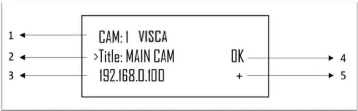
| No | Item Function Descriptions | |
| 1 | Camera ID and protocol | Display the camera currently under control and the protocol currently in use |
| 2 | Camera name Display | the specified camera name currently in use |
| 3 | IP address Current IP address of the camera | |
| 4 | Communication status of the connected device | If “OK” is displayed, communication with the current device has been establishedIf “NO” is displayed, there is no connection with the current device |
| 5 | Network connection indication status | If “+” is displayed, the network is connected successfullyIf “+” is not displayed, the network is not connected correctly |
Chapter 3 LCD Function Menu Description
3.1 Access LCD Function Menu
Press the SETUP button on the keyboard to access the LCD function menu.
※ When configuring the LCD menu setting, you must key in the password every time (initial password is 0000)

3.2 Camera Setting
■ CAMERA SETTING
| Item Settings Description | ||
| CAM 1 ~ 255 | Assign the camera number; 255 units can be set at most | |
| Title | - | The camera can be named using letters on the keyboard |
| Protocol | VISCAPELCO-DPELCO-PVISCAIP | Select a control protocol to be used for connecting the camera |
■ VISCA / PELCO-D / PELCO-P advanced setting
| Item Settings Description | ||
| Baud Rate | 2400480096001920038400 | When selecting VISCA / PELCO-D /PELCO-P as the control protocol, the Baud rate transmission speed must be specified |
| Port | RS232/ RS422 | Set the control method of VISCA control |
■ VISCAIP advanced setting
| Item Settings Description | ||
| IP Address | 192.168.0.168 | Set the camera IP address |
| User Name | admin | Access the camera account |
| Password | admin | Set the camera password |
| Port | 80 | Select a port to be used by the camera |
3.3 Keyboard setting
■ IP Configuration Menu
| Item Settings Description | ||
| Type STATIC / DHCP | Specify a static IP or let DHCP to assign an IP to the keyboard | |
| IP Address | 192.168.0.100 | For a static IP, specify the IP address in this field(Default IP is 192.168.0.100) |
| Subnet Mask | 255.255.255.0 | For a static IP, specify the subnet mask in this field |
| Gateway | 192.168.0.1 | For a static IP, specify the gateway in this field |
■ BUTTON LIGHT
| Item Settings Description | ||
| Level | 1 / 2 / 3 | Set background brightness of the keyboard buttons |
■ ASSIGNED KEY
| Item Settings Description | ||
| F1 ~ F6 | Camera 1 ~ 6HomeP/T ResetPowerMutePicture FreezePicture FlipPictureLR_ReverseNone | F1 ~ F6 buttons can be set as shortcut keys separatelyFunctions may be set as the list displayed to the leftPress the shortcut key and the camera will perform the specified function quickly |
■ FACTORY DEFAULT
| Item Settings Description | ||
| FACTORY DEFAULT | Yes / No | Execute the factory reset on the keyboard LCD menu functionsAfter the reset is completed, “Succeed” will be displayed※ When executing the factory reset, do not move the PTZ joystick and the ZOOM in/out button |
■ GPI I/O
| Item Settings Description | ||
| Setting Input / Output | Set the control signal direction of GPI I/O interface as Input or Output | |
| Tally Mode | Normal / On Air | Display the Tally input indicator that corresponds to the camera number having the Tally input as ON. When the setting is Normal, the camera is selected as the target camera automatically |
| Command Sel | Standard / Expand | Set the camera number to be standard or binary processing |
| Camera Link | On / Off | Enable or disable Tally indicator control |
■ PASSWORD SETTING
| Item Description | |
| Old Password | Key in the current password(initial password is 0000) |
| New Password | Key in a new password |
| Confirm | Enter the new password again |
| Save | Preset Save |
■ JOYSTICK ZOOM
| Item Settings Description | ||
| JOKSTICK ZOOM | ON / OFF | Specify whether to enable the joystick ZOOM function |
■ MODEL INFO
| Item Description | |
| >IP Address :192. 168. 0. 100FW Version : 0.6.7LIP V2.5 Exit | Display the IP address that controls the keyboard and FW version |
Chapter 4 Camera Connection Description
VS-KB30 supports crossing protocol hybrid control between RS232, RS422 and IP.
Supported control protocols include: VISCA, PELCO D / P, VISCA over IP
4.1 Port Pin Definition
| TALLY/CONTACT | RS-232 | IP | RS-422 (A/B) | |||||||
| 1 | 8 | 1 | 8 | 1 | 8 | |||||
| Pin No. | Function | Pin No. | Function | Color | Pin No. | Function | Color | Pin No. | Function | Color |
| 1 | CAMERA1 | 1 | - | Orange/White | 1 | TX+ | Orange/White | 1 | TX- | Orange/White |
| 2 | CAMERA2 | 2 | - | Orange | 2 | TX- | Orange | 2 | TX+ | Orange |
| 3 | CAMERA3 | 3 | GND | Green/White | 3 | RX+ | Green/White | 3 | GND | Green/White |
| 4 | CAMERA4 | 4 | - | Blue | 4 | n/c | Blue | 4 | - | Blue |
| 5 | CAMERA5 | 5 | - | Blue/White | 5 | n/c | Blue/White | 5 | - | Blue/White |
| 6 | CAMERA6 | 6 | GND | Green | 6 | RX- | Green | 6 | - | Green |
| 7 | CAMERA7 | 7 | TXD | Brown/White | 7 | n/c | Brown/White | 7 | RX- | Brown/White |
| 8 | GND | 8 | RXD | Brown | 8 | n/c | Brown | 8 | RX+ | Brown |
| 9 | GND | |||||||||
4.2 How to Connect RS-232
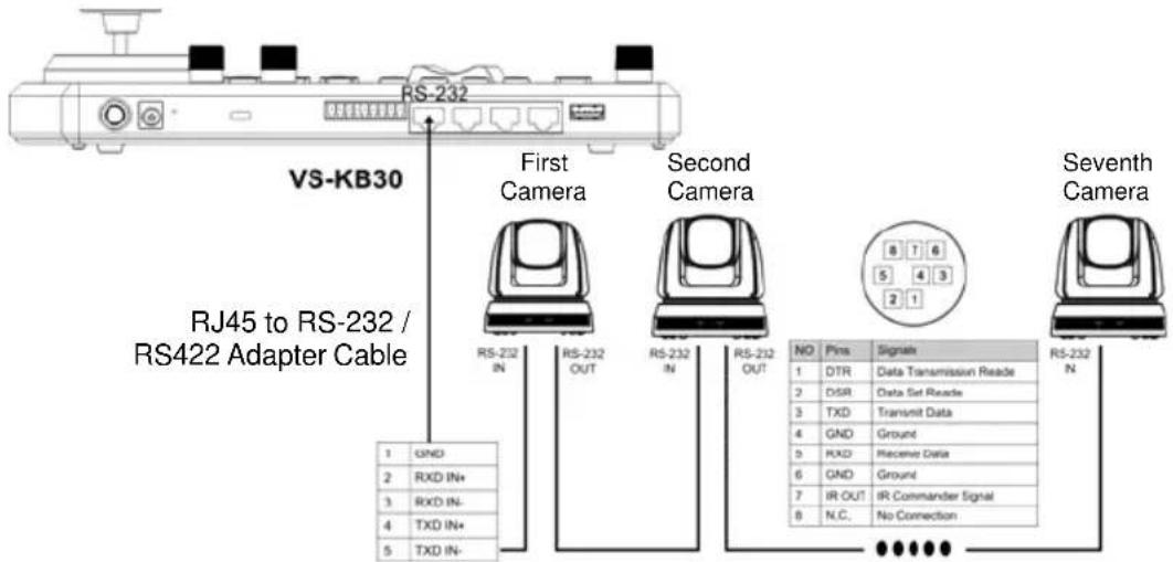
- Connect the RJ-45 to RS232 adapter cable to the RS232 port of VS-KB30
- Please refer to the RJ-45 to RS232 adapter cable and camera Mini Din RS232 pin definitions to complete the cable connection
[Remark] Please make sure that SYSTEM SWITCH DIP1 and DIP3 on the bottom of Lumens camera are set as OFF (RS232 & baud rate 9600)
[Note] VC-AC07 is optional and can be connected via network cable
4.3 How to Connect RS-422
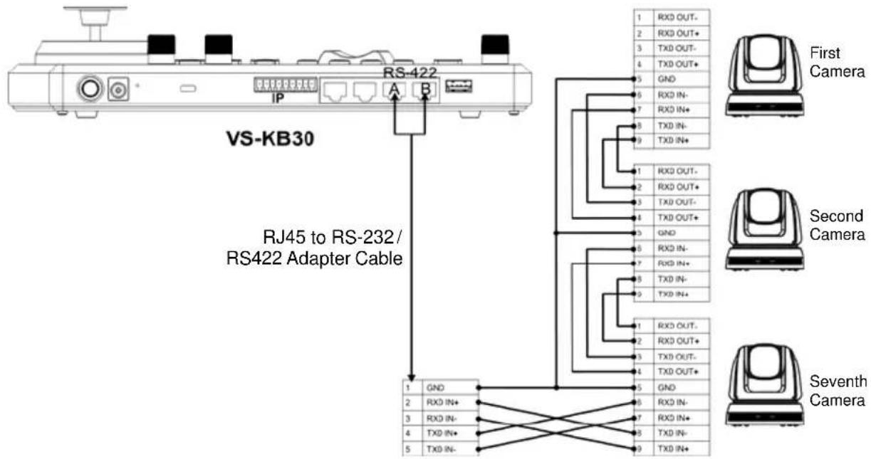
- Connect the RJ-45 to RS232 adapter cable to the RS422 port of VS-KB30 (A or B)
- Please refer to the RJ-45 to RS232 adapter cable and camera RS422 pin definitions to complete the cable connection
[Remark] Please make sure that SYSTEM SWITCH DIP1 and DIP3 on the bottom of Lumens camera are set as ON and OFF respectively (RS422 & baud rate 9600)
4.4 How to Connect IP
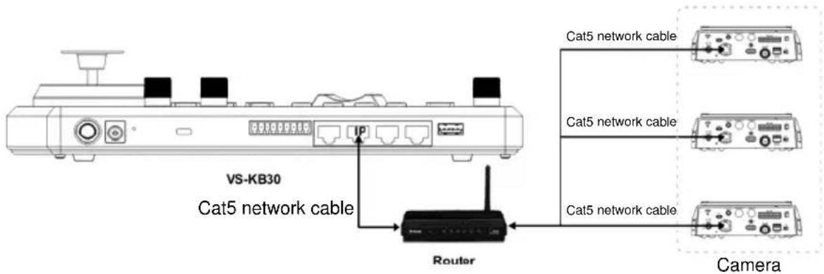
- Use network cables to connect VS-KB30 and IP camera to the router
5.1 Power on VS-KB30
Two types of power supply can be used by VS-KB30
■ DC 12 V power supply: Please use the included DC power supply adapter and power cable, and press the power button

■ POE power supply: Use Ethernet cables to connect POE switch and IP port of VS-KB30, and press the POWER button
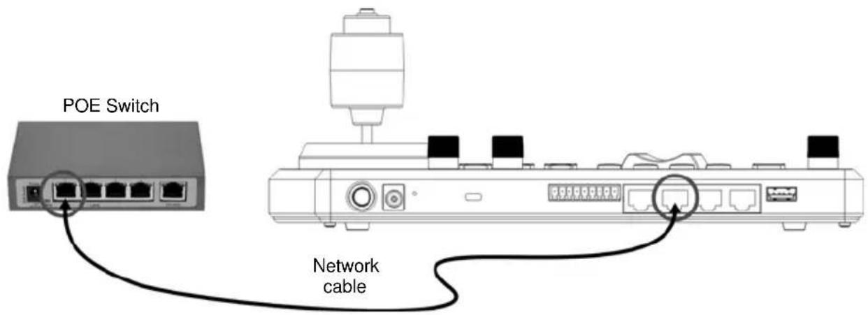
[Note] RJ45 ports of RS232 and RS422 do not support POE. Please do not connect with POE-powered network cables
5.2 Instruction on RS-232 Setting
■ Press SETUP, and select CAMERA SETTING
■ Set CAMID and Title
■ After protocol is set as VISCA, press P/T SPEED to access the advanced setting
Baud Rate is set as 9600
▶ Port is set as RS232
■ Press EXIT to exit
5.3 Instruction on RS-422 Setting
■ Press SETUP, and select CAMERA SETTING
■ Set CAMID and Title
■ After protocol is set as VISCA, press P/T SPEED to access the advanced setting
Baud Rate is set as 9600
Port is set as RS422
■ Press EXIT to exit
5.4 Instruction on IP Setting
5.4.1 Set VS-KB30 IP address
■ Press SETUP, and select KEYBOARD SETTING => IP CONFIGURATION
■ Type: Select STATIC or DHCP
■ IP Address: If select STATIC, use P/T SPEED to choose the location, input IP address via numbers on the keyboard. Last, press ZOOM SPEED to save and exit
5.4.2 Add Cameras
1. Automatic Search

flowchart
graph LR
    A["SEARCH"] --> B["SELECT PROTOCOL\n>VISCA-IP\nEXIT"]
    B --> C["Start Search?\n>Yes\nNo & Exit"]
    C --> D["Searched Cam: 1/5\n>192.168.0.101\nEXIT"]
■ Press SERTCH
■ Select VISCA-IP
➢ VISCA-IP: Search available VISCA over IP cameras on the internet
■ Press ZOOM SPEED to save; then press EXIT to exit
2. Manual Add
■ Press SETUP, and select CAMERA SETTING
■ Set CAMID and Title
■ Protocol Select VISCA-IP, and set the camera IP address
■ Press ZOOM SPEED to save; then press EXIT to exit
Chapter 6 Descriptions of Major Functions
6.1 Call the Camera
6.1.1 Use the digital keyboard to call the camera
- Key in the camera number to be called via keyboard
- Press the "CAM" button

flowchart
graph LR
    A["7 PQRS"] --> B["8 TUV"]
    B --> C["9 WXYZ"]
    D["4 GHI"] --> E["5 JKL"]
    E --> F["6 MNO"]
    G["1"] --> H["2 ABC"]
    H --> I["3 DEF"]
    J["0"] --> K["Cam"]
6.1.2 Call the IP camera via device list
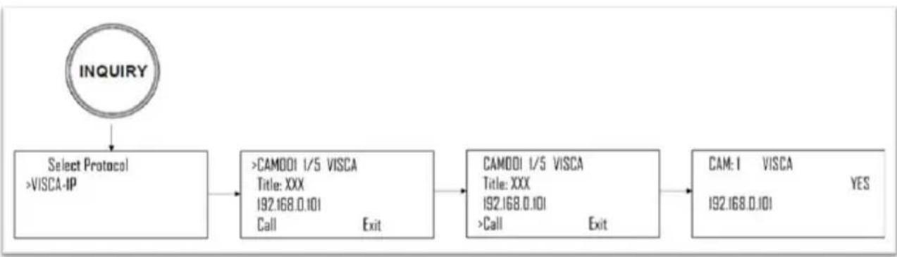
flowchart
graph TD
    A["INQUIRY"] --> B["Select Protocol\n>VISCA-IP"]
    B --> C[">CAMDDI 1/5 VISCA\nTitle: XXX\n192.168.0.101\nCall Exit"]
    C --> D["CAMDDI 1/5 VISCA\nTitle: XXX\n192.168.0.101\n>Call Exit"]
    D --> E["CAM-I VISCA\n192.168.0.101 YES"]
- Press the "INQUIRY" button
- Select the IP camera protocol
- Use the ZOOM SPEED button to select the camera to be controlled
- Select "CALL" and press the P/T SPEED button to confirm
6.2 Setup/Call/Cancel Preset Position.
6.2.1 Specify the preset position
- Relocate the camera to the desired position
- Enter the desired preset position number, then press and hold the PRESET button for 3 seconds to save
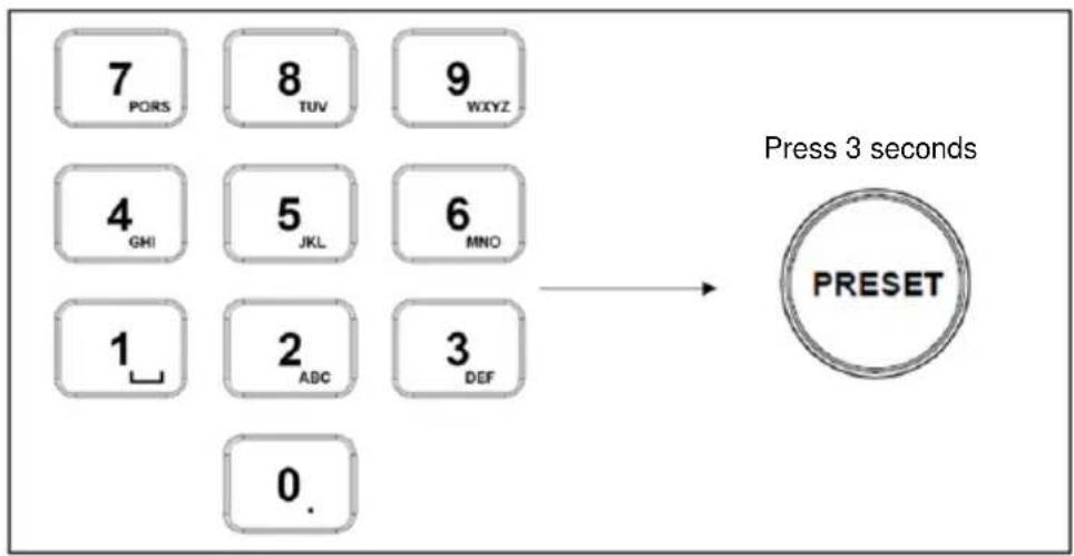
flowchart
graph LR
    A["7 PORS"] --> B["8 TUV"]
    B --> C["9 WXYZ"]
    D["4 GHI"] --> E["5 JKL"]
    E --> F["6 MNO"]
    G["1"] --> H["2 ABC"]
    H --> I["3 DEF"]
    J["0."] --> K["Press 3 seconds"]
    L["PRESET"] --> K
6.2.2 Call the preset position
- Key in the desired preset position number via keyboard
- Press "CALL" button

flowchart
graph LR
    A["7 PORS"] --> B["8 TUV"]
    B --> C["9 WXYZ"]
    D["4 GHI"] --> E["5 JKL"]
    E --> F["6 MNO"]
    G["1"] --> H["2 ABC"]
    H --> I["3 DEF"]
    J["0."] --> K["CALL"]
    L["Press "CALL""] --> K
6.2.3 Cancel the preset position
- Key in the preset position number to be deleted
- Press "RESET" button

flowchart
graph LR
    A["7 PQRS"] --> B["8 TUY"]
    B --> C["9 WXYZ"]
    D["4 OHI"] --> E["5 JKL"]
    E --> F["6 MNO"]
    G["1"] --> H["2 ABC"]
    H --> I["3 DEF"]
    J["0."] --> K["Press "RESET""]
    K --> L["RESET"]
6.3 Set the Non-IP Camera OSD Menu via Keyboard
- Press the "MENU" button on the keyboard
- Set the camera OSD menu via PTZ joystick
■ Move the joystick up and down. Switch the menu items/Tune the parameter values
■ Move the joystick to the right: Enter
■ Move the joystick to the left: Exit

flowchart
graph LR
    A["MENU"] --> B["Arrow"]
    B --> C["Right Arrow"]
    B --> D["Left Arrow"]
    B --> E["Down Arrow"]
6.4 Set the PELCO-D Camera OSD Menu via Keyboard
- Use the numeric keyboard to key in "95" + "CALL" button

6.5 RS422 Set A, Set B Switching
- Press the A or B buttons to switch between RS422 sets (buttons of the set in use will be lit)

This Chapter describes questions frequently asked during the use of VS-KB30 and suggests methods and solutions.
| No. | Problems Solutions | |
| 1 | After plugging in the power supply, VS-KB30 power is not on | Please check whether the power button on the back is pressed down correctlyIf POE is used, please make sure the Ethernet network cable is correctly connected to the power port of the POE switch |
| 2 | VS-KB30 camera cannot be controlled | Please confirm the port pin connection is correct (RS-232/422)Please confirm whether the camera system switch DIP 1 ad DIP 3 are set correctly.Please confirm whether the MENU button on the keyboard is pressed down by mistake, causing the camera OSD menu to open and the camera unable to be controlled |
| 3 | Cannot use the keyboard buttons to change the image settings or focus | Please confirm the LOCK button is set in “LOCK” mode |
※For questions about the installation, please scan the following QR Code. A support person will be assigned to assist you

SERVICE
Supplier's Declaration of Conformity 47 CFR § 2.1077 Compliance Information
Manufacturer: Lumens Digital Optics Inc.
Product Name: VS-KB30
Model Number: Keyboard Controller
Responsible Party - U.S. Contact Information
Supplier: Lumens Integration, Inc.
4116 Clipper Court, Fremont, CA 94538, United States
e-mail : support@mylumens.com
FCC Compliance Statement
This device complies with Part 15 of the FCC Rules. Operation is subject to the following two conditions: (1) This device may not cause harmful interference, and (2) this device must accept any interference received, including interference that may cause undesired operation.
- User Manual - English
- [Important]
- Table of Contents
- Copyright Information......3
- Chapter 1 Safety Instructions ....4
- Chapter 2 Product Overview....6
- Chapter 3 LCD Function Menu Description....10
- Chapter 4 Camera Connection Description....14
- Chapter 5 Camera Setting Description ...... 16
- Chapter 6 Descriptions of Major Functions....19
- Chapter 7 Troubleshooting....23
- ■ Precautions
- ■ FCC Warning
- Panel Function Introduction
- LCD Screen Display Description
- Chapter 3 LCD Function Menu Description
- Access LCD Function Menu
- Camera Setting
- ■ CAMERA SETTING
- ■ VISCA / PELCO-D / PELCO-P advanced setting
- ■ VISCAIP advanced setting
- Keyboard setting
- ■ IP Configuration Menu
- ■ BUTTON LIGHT
- ■ ASSIGNED KEY
- Chapter 4 Camera Connection Description
- Port Pin Definition
- How to Connect RS-232
- How to Connect RS-422
- How to Connect IP
- Power on VS-KB30
- Instruction on RS-232 Setting
- Instruction on RS-422 Setting
- Instruction on IP Setting
- Set VS-KB30 IP address
- Add Cameras
- Automatic Search
- Manual Add
- Chapter 6 Descriptions of Major Functions
- Call the Camera
- Use the digital keyboard to call the camera
- Call the IP camera via device list
- Setup/Call/Cancel Preset Position.
- Specify the preset position
- Call the preset position
- Cancel the preset position
- Set the Non-IP Camera OSD Menu via Keyboard
- Set the PELCO-D Camera OSD Menu via Keyboard
- RS422 Set A, Set B Switching
- Supplier's Declaration of Conformity 47 CFR § 2.1077 Compliance Information
- Responsible Party - U.S. Contact Information
- FCC Compliance Statement
Brand : Lumens
Model : VS-KB30
Category : Regulator