
DC-16 - Mixing console MACKIE - Free user manual and instructions
Find the device manual for free DC-16 MACKIE in PDF.


| Type | Digital mixing console control surface (requires DL32R) |
| Dimensions (H x W x D) | 3.3 x 36.8 x 17.6 in (84 x 935 x 447 mm) |
| Weight | 38.0 lb (17 kg) |
| Power Consumption | 102 W |
| Power Supply | External, 100–240 VAC, 50–60 Hz, output 12 VDC 8.5 A |
| Sample Rate | 48 kHz |
| Bit Depth | 24-bit |
| Frequency Response | ±0, -1 dB, 20 Hz – 20 kHz |
| Stereo Input | 1/8" unbalanced, max +16 dBu |
| Talkback Mic Input | XLR balanced, 0–60 dB gain, Onyx preamp |
| Monitor Outputs (L/R) | 1/4" TRS balanced, max +21 dBu |
| Headphone Output | 1/4" TRS stereo, +18 dBu into 600 Ω |
| Dante Connectivity | 2x EtherCon Gigabit Ethernet, 4x4 channels, 48 kHz, 24-bit |
| Network Control | Gigabit Ethernet, Wi-Fi control port |
| iPad Connectivity | 1x USB-A (control, audio, charging) + 2x USB-A (charging only) |
| Faders | 16+1 100 mm motorized touch-sensitive faders |
| Channel Strips | 16 input channels + 1 master channel |
| Channel Displays | 17 color TFT displays (1 selected + 16 channel) |
| Phantom Power | 48 V via DL32R |
| Operating Temperature | 0–40 °C (32–104 °F) |
| Included Accessories | Locking power supply, IEC cable, documentation |
Frequently Asked Questions - DC-16 MACKIE
User questions about DC-16 MACKIE
0 question about this device. Answer the ones you know or ask your own.
Ask a new question about this device
Download the instructions for your Mixing console in PDF format for free! Find your manual DC-16 - MACKIE and take your electronic device back in hand. On this page are published all the documents necessary for the use of your device. DC-16 by MACKIE.
USER MANUAL DC-16 MACKIE
natural_image
Symbolic icon of a running person inside a circle, no text or numbers presentDC16
OWNER'S MANUAL

MACKIE.®
SOUND LIKE YOU MEAN IT®
Important Safety Instructions
- Read these instructions.
- Keep these instructions.
- Heed all warnings.
- Follow all instructions.
- Do not use this apparatus near water.
- Clean only with a dry cloth.
- Do not block any ventilation openings. Install in accordance with the manufacturer's instructions.
- Do not install near any heat sources such as radiators, heat registers, stoves, or other apparatus (including amplifiers) that produce heat.
- Do not defeat the safety purpose of the polarized or grounding-type plug. A polarized plug has two blades with one wider than the other. A grounding-type plug has two blades and a third grounding prong. The wide blade or the third prong are provided for your safety. If the provided plug does not fit into your outlet, consult an electrician for replacement of the obsolete outlet.
- Protect the power cord from being walked on or pinched particularly at plugs, convenience receptacles, and the point where they exit from the apparatus.
- Only use attachments/accessories specified by the manufacturer.
- Use only with a cart, stand, tripod, bracket, or table specified by the manufacturer, or sold with the apparatus. When a cart is used, use caution when moving the cart/apparatus combination to avoid injury from tip-over.
- Unplug this apparatus during lightning storms or when unused for long periods of time.
- Refer all servicing to qualified service personnel. Servicing is required when the apparatus has been damaged in any way, such as power-supply cord or plug is damaged, liquid has been spilled or objects have fallen into the apparatus, the apparatus has been exposed to rain or moisture, does not operate normally, or has been dropped.
- This apparatus shall not be exposed to dripping or splashing, and no object filled with liquids, such as vases or beer glasses, shall be placed on the apparatus.
- Do not overload wall outlets and extension cords as this can result in a risk of fire or electric shock.
- The MAINS plug or an appliance coupler is used as the disconnect device, so the disconnect device shall remain readily operable.


The lightning flash with arrowhead symbol within an equilateral triangle is intended to alert the user to the presence of uninsulated "dangerous voltage" within the product's enclosure, that may be of significant magnitude to constitute a risk of electric shock to persons.

The exclamation point within an equilateral triangle is intended to alert the user of the presence of important operating and maintaining (servicing) instructions in the literature accompanying the appliance.
- NOTE: This equipment has been tested and found to comply with the limits for a Class B digital device, pursuant to part 15 of the FCC Rules. These limits are designed to provide reasonable protection against harmful interference in a residential installation. This equipment generates, uses, and can radiate radio frequency energy and, if not installed and used in accordance with the instructions, may cause harmful interference to radio communications. However, there is no guarantee that interference will not occur in a particular installation. If this equipment does cause harmful interference to radio or television reception, which can be determined by turning the equipment off and on, the user is encouraged to try to correct the interference by one or more of the following measures:
• Reorient or relocate the receiving antenna.
- Increase the separation between the equipment and the receiver.
- Connect the equipment into an outlet on a circuit different from that to which the receiver is connected.
- Consult the dealer or an experienced radio/TV technician for help.
CAUTION: Changes or modifications to this device not expressly approved by LOUD Audio, LLC. could void the user's authority to operate the equipment under FCC rules.
- This apparatus does not exceed the Class A/Class B (whichever is applicable) limits for radio noise emissions from digital apparatus as set out in the radio interference regulations of the Canadian Department of Communications.
ATTENTION — Le présent appareil numérique n'émet pas de bruits radioélectriques dépassant las limites applicables aux appareils numériques de class A/de class B (selon le cas) prescrites dans le règlement sur le brouillage radioélectrique édicté par les ministère des communications du Canada. - Exposure to extremely high noise levels may cause permanent hearing loss. Individuals vary considerably in susceptibility to noise-induced hearing loss, but nearly everyone will lose some hearing if exposed to sufficiently intense noise for a period of time. The U.S. Government's Occupational Safety and Health Administration (OSHA) has specified the permissible noise level exposures shown in the following chart.
According to OSHA, any exposure in excess of these permissible limits could result in some hearing loss. To ensure against potentially dangerous exposure to high sound pressure levels, it is recommended that all persons exposed to equipment capable of producing high sound pressure levels use hearing protectors while the equipment is in operation. Ear plugs or protectors in the ear canals or over the ears must be worn when operating the equipment in order to prevent permanent hearing loss if exposure is in excess of the limits set forth here:
| Duration, per day in hours | Sound Level dBA, Slow Response | Typical Example |
| 8 90 Duo in small club | ||
| 6 | 92 | |
| 4 95 Subway Train | ||
| 3 | 97 | |
| 2 100 Very loud classical music | ||
| 1.5 102 | ||
| 1 105 | Chaz screaming at Troy about deadlines | |
| 0.5 | 110 | |
| 0.25 or less | 115 | Loudest parts at a rock concert |
WARNING — To reduce the risk of fire or electric shock, do not expose this apparatus to rain or moisture.

Correct Disposal of this product: This symbol indicates that this product should not be disposed of with your household waste, according to the WEEE Directive (2012/19/EU) and your national law. This product should be handed over to an authorized collection site for recycling waste electrical and electronic equipment (EEE). Improper handling of this type of waste could have a possible negative impact on the environment and human health due to potentially hazardous substances that are generally associated with EEE. At the same time, your cooperation in the correct disposal of this product will contribute to the effective usage of natural resources. For more information about where you can drop off your waste equipment for recycling, please contact your local city office, waste authority, or your household waste disposal service.
Table of Contents
Important Safety Instructions....2
Table Of Contents....3
Chapter 1: Welcome......6
Chapter 2 : Getting Started....7
Chapter 3 : A Closer Look at Slots and Dante ....10
Introduction 10
Slots 10
Dante 11
Why Use Dante?......11
Dante Routing ....11
Chapter 4 : DC16 Front and Rear Panels....17
Front Panel Introduction....17
Phones Jacks 17
Rear Panel Introduction....18
Talkback Mic Input....18
1/8" Stereo In Jack....18
1/4" Monitor L/R Outputs....18
1/4" Footswitch Jack....19
Dante A / B....19
Force Update Button 20
Wi-Fi Control 20
Tablet Control and Charging USB Inputs ....20
Power Connector 21
Power Switch....21
Lamp Input Jack 21
Chapter 5: DC16 Top Panel 22
Top Panel Introduction 22
Input Channels / Master Channel....23
SEL (Select) Buttons....23
MUTE Buttons 23
100 mm motorized touch sensitive faders 23
Gain Reduction LEDs....24
Level Meter LEDs....24
Mix Select LEDs 24
SOLO Buttons 24
Channel Screens Overview 25
Channel Displays and Encoders....25
Channel Editing Page Buttons....26
Banking Group Selector 26
BANK Buttons....26
CHANNEL Buttons....26
Groups Selector 27
VIEW Group Button 27
MUTE Group Button 29
USER Button 31
CHANNEL Button 33
Mix Selector 37
Page Buttons 38
MAST(er) Button....44
CLEAR SOLO Button....46
TALK(back) Button 46
Channel Editing......47
All Channel Editing
GAIN / TRIM Button....48
HPF / LPF Button 49
SEND / DELAY Button 50
PAN / USER Button 52
Selected Channel Editing
EQ / ASSIGN Button....54
GEO / SENDS Button 56
DYN(amics) / Setup Button 58, 86
FX / TRANS(port) Button....60
Fat Channel 63
GAIN Encoder 63
TRIM Encoder (ALT + GAIN) 63
48v Phantom Power Button....64
Polarity Invert [0] Button....64
HPF Encoder 64
LPF Encoder (ALT + HPF) 64
Four-band Parametric EQ Buttons and Encoders [GAIN, FREQ, Q] 64
GATE THRESH Encoder 65
GATE RANGE Encoder (ALT + GATE THRESH) 65
COMP THRESH Encoder....65
COMP RATIO Encoder (ALT + COMP THRESH) 65
PAN Encoder 65
DELAY Encoder (ALT + PAN) 65
Snapshot Control......66
Display 66
Arrow Buttons 66
RECALL Button....67
STORE Button....67
MORE Button....67
Analog Controls 68
TALKBACK Knob 68
MONITOR Knob 68
PHONES Knob....68
Modifiers 69
ALT Button....69
SHIFT Button....69
ASGN Button....70
LOCK Button....72
Smart Bridge 76
Tablet Setup....77
Controllers....77
DC16 Slot 77
Position 78
Follow Mode 78
Follow Mode....78
Current Selected Channel....79
Selected Channel History....79
Fixed View 79
Advanced 80
Surface To Wireless Mixing....81
Examples of Follow Mode 81
Chapter 6 : DC16 Tips and Tricks ...... 95
Subgroup / VCA Mix Spill 95
Appendix A : Hookup Diagram....96
Appendix B : Technical Information....97
Specifications 97
DC16 Dimensional Drawings 100
Appendix C : Service Information ......102
Warranty Statement / GPL Statement....104
Chapter 1: Welcome
Hello everyone! This is the DC16 Owner's Manual... we hope you like it!
Instead of one massive document containing detailed information about the hardware and software, we have divided them into separate manuals. Simply decide if you need assistance with the DC16 control surface hardware or Master Fader control app and dive on in. The water here is warm and crystal clear.
The following pages (mostly) describe the hardware side of things and should remain relatively unchanged throughout the life of your product. The software, though, is another story. The Master Fader app is always being updated... even right now this very minute! This means frequent updates to the Reference Guide, firmware and more. With each major release comes an updated Reference Guide.

To say (almost) the exact same thing again – but with different words and a "Note" – the information detailed on the following pages is how to use and control the DC16. There is little to no explanation regarding Master Fader. For that, we urge you to read and review the latest Master Fader Reference Guide.

You probably already know this, but in case not, a DL32R and Master Fader will work without a DC16, but a DC16 cannot work without a DL32R and Master Fader.
So there you have it. Again, we hope you like it. If you have any questions or comments about this Owner's Manual, please contact us at: www.mackie.com/support
About This Guide
This guide is designed to be accessible, with subsections as complete as practical to minimize having to electronically leaf back and forth looking for the whole story. This guide provides the following resources:
- A general overview of the DC16's facilities and features.
- Dissection-by-dissection description of each button, knob, fader, screen, encoder, LED and input and output.
- Hookup diagrams depicting some of the more common setups.
As the saying goes, “a picture tells a 1000 words”. With that thought in mind, we added quite a few illustrations, screen shots and other images throughout to accompany the text.

This icon marks information that is critically important or unique! For your own good, read and remember them... it is a good idea to pay special attention to these areas in the Owner's Manual marked with the "VERY IMPORTANT" hand icon.

There's an illustration of a microscope, so, of course, you're going to get more detailed information when you see this little guy. There are explanations of features and practical tips listed here.

It's a good idea to pay attention to text displayed next to a note icon, as this icon draws attention to certain features and functions relating to the usage of the mixer.
Hey, look above... two "Note" icons have already been used! Hopefully they didn't throw you for a loop.
Chapter 2: Getting Started
The following instructions will help you get your system set up and started in no time. You should only have to follow these instructions once and then you will be well on your way to a beautiful future of mixing.
This upgrade can take up to 30 minutes, so follow these steps well in advance of a show, demo or other event.

I. Be sure to perform a full System Backup of Master Fader - Tools > Settings > System Backup.

-
Follow THESE AXIS UPGRADE INSTRUCTIONS' (with thanks to our wonderful Technical Support team!).
-
Plug signal sources into the DL32R, such as:
-
Microphones plugged into the mic inputs.
• Line-level sources such as keyboards, drum machines, or MP3 players plugged into the line-level inputs. -
Connect XLR outputs I3 and I4 of the DL32R to powered speakers (or to an amplifier connected to passive speakers).
-
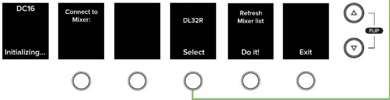
Turn the DL32R on first and the DC16 on second. [Technically the DC16 will still be able to discover the DL32R if the DC16 is powered on first, but you might be required to refresh the mixer list the DC16 received.] Follow the on-screen instructions of the DC16 – as seen in the images below (and next two pages) – to pair.
(A) - Nothing to do here, but wait!

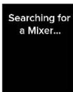

(B) - Push the encoder in to select the DL32R.
flowchart
graph LR
    A["DC16<br>Initializing..."] --> B["Connect to Mixer:"]
    B --> C["Select"]
    C --> D["DL32R"]
    D --> E["Refresh Mixer list"]
    E --> F["Exit"]
    F --> G["FLIP"]
    G --> H["△"]
    G --> I["▽"]
(C) - We'll assume here that you will only be using a single DC16 at this time. Therefore, push the encoder in to select the FOH slot.

flowchart
graph LR
    A["DC16<br>Initializing..."] --> B["Select DL32R connection"]
    B --> C["FOH<br>empty"]
    C --> D["MON<br>empty"]
    D --> E["3<br>empty"]
    E --> F["4<br>empty slot"]
(D) – Once selected, DC16 will ask if you want to auto route Dante and DL32R. Dante Auto Route configures the headphones, monitors, talkback and stereo playback and recording signals between the DL32R and DC16. You will almost unequivocally desire to auto route Dante, so push the "Yes" encoder to confirm. Or press the "No" encoder if you prefer to customize the Dante routing.

(E) - Hang tight and let DC16, DL32R and Dante do its thing then you'll be on your way!
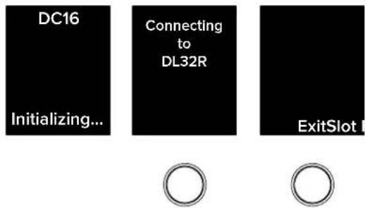
- Turn the powered speakers (or amplifiers) on.
- Connect an iPad to the iPad Control Port (located on the rear panel of DC16), launch the Master Fader app and connect to the DL32R / DC16 (as explained in the Master Fader Reference Guide 'Devices' section).
- Set the volume of the source input, starting with channel one.
- Adjust the channel's mic pre gain until the meters on that channel bounce between green and yellow. Engage phantom power if needed.
- Move the channel's fader up to the 0 dB mark.
II. Slowly move the master fader up to a comfortable listening level. - Repeat steps 8 to 10 for the other channels.
There are detailed notes outlined in the Master Fader Reference Guide -Chapter 4: Level Setting Procedure.
Chapter 3: A Closer Look at Slots and Dante
Introduction
In the previous chapter – Chapter 2: Getting Started – we suggested selecting the FOH slot and auto-routing Dante. We're not changing our minds already, but what do these things mean? What did you do by selecting the FOH slot and auto-routing Dante?
Changing the slot and customizing Dante routing occurs in Setup - ALT + DYN, see pages 86-94 - and Master Fader, but here we're just taking a look at what took place when you made those selections.
Slots
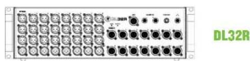
Each DL32R can handle four slots [FOH, MON, 3 and 4]. This means that multiple DCI6s may be connected to a single DL32R. For example, up to four DCI6s may be connected to a single DL32R: one as FOH, one as MON, one as slot 3 and one as slot 4. That scenario is highly unlikely, but it is possible. Having said that, the opposite is not true: a single DCI6 cannot connect to multiple DL32Rs. But it can easily switch between them.
As mentioned above, utilizing slots 3 and 4 is unlikely, as it's used on more complicated systems, such as broadcasting or two FOH engineers. That said, we'll show you a more common setup (besides a single FOH DC16 connected to a single DL32R). Here we have two DC16's connected to a single DL32R.
One DC16 is used at FOH and another is side stage for MON. They are physically connected via the Dante cards, FOH Dante A to DL32R Dante A and MON Dante B to DL32R Dante B. And as mentioned previously, the DL32R is on the network connected to the Wi-Fi port.
We already set up the FOH DC16, but need to select the MON slot for the MON DC16 as described on page 86. Additionally, you will need to set up the DC16 Slot's Follow Mode [Tools > Controllers > DC16 Slot] on each tablet. More information about this is described on page 77.
FOH

natural_image
Front panel of a multi-pin electronic device with multiple ports and connectors (no visible text or symbols)MON

Each DL32R will be labeled the custom name you gave it, but the default is DL32R (which is what we named it in our example above.).
Renaming the DL32R has already been described in detail in the Master Fader Reference Guide (in the Tools > Devices section), but did you know that each DC16 may be named, as well? It is done the same exact way, but for DC16. Doing so requires a fast (and automatic) reboot.
Dante
Dante – Digital Audio Network Through Ethernet – is the de facto standard in digital audio networking, delivering unmatched audio quality, extremely flexible routing and offers significant cost savings compared to traditional analog cable runs.
The dual Dante ports allow daisy chaining and the dedicated Wi-Fi control port eliminates the need for an Ethernet switch in many situations.
Here, you should use a shielded network cable that is CAT5E (or better) to connect DC16 to the DL32R. This allows for control, monitoring, talkback and more. Additionally, the Dante ports may also be used to connect to other Dante-enabled audio networks. As such, it is a perfect solution for connecting to a Dante-enabled loudspeaker system.
With flawless interoperation with hundreds of Dante-enabled products and a rock solid, glitch-free operation, the Dante connectors truly expand the DC16's functionality and application-flexibility in any professional environment.
Why Use Dante?
Why use Dante? There simply isn't enough space here to explain all of the benefits of Dante, but here's a small sampling:
• Automatic configuration
• Uncompressed low latency digital audio
• High channel count: up to 1024 (5I2 x 5I2) channels per link
• Maximum sampling rate: 192 kHz
• Maximum bit depth: 32 bits
- Switchable and routable
- Can easily handle long distances and/or multiple locations
• Daisy-chain or use for system redundancy
- Massive cost savings
Dante Routing
For all intents and purposes, you will most likely want to auto-route Dante and DL32R. It's fast, easy and reliable as it configures the headphones, monitors, talkback and stereo playback and recording signals between the DL32R and DC16.
The Mackie Technical Support team wrote a long, beautiful setup guide for Dante. If you're a Dante wizard, then you can probably pass this section, but if not, you should probably check out the Dante Setup Guide HERE ^1 .
Dante Controller is a free software application that is available for both Windows and Mac OS X:
https://www.audinate.com/products/software/dante-controller
So what's really happening when you to choose to auto-route Dante? Let's take a look at the under-the-hood changes taking place. As mentioned on the previous page auto-routing Dante "...configures the headphones, monitors, talkback and stereo playback and recording signals between the DL32R and DC16."
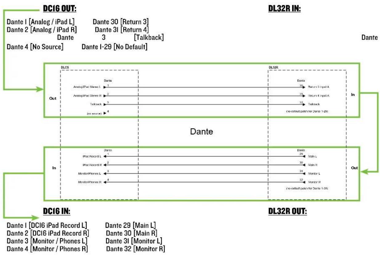
In short, you're setting up a monitor mix FOR DC16 FROM DL32R. That is, what goes TO the DC16 headphone and monitor outputs is a mirror image of the DL32R headphones and monitor outputs. The L/R FROM DL32R TO DC16 feeds the iPad record input, the record input being a stereo L/R mix recording. Words are cool and all, but pictures, drawings and such are so much cooler. Please flip the page!
Stereo Source
The Stereo Source is what's auto-routed, so let's start there. It's a part of Setup - ALT + DYN, see pages 86-94 - but explained in more detail below.
Shown below is the standard signal flow routing. Notice how the DC16 iPad L/R (Dante 1-2, OUT) is auto routed to the DL32R Return 3/4 (Dante 30-31, IN). [Talkback is routed from Dante 3 to Dante 32].
Then, on the return, it leaves the DL32R Main L/R (Dante 29-30, OUT) and Monitor L/R (Dante 31-32, OUT) and goes to the DC16 iPad L/R (Dante I-2, IN) and Monitor/Phones L/R (Dante 3-4, IN):
flowchart
graph TD
    subgraph DLCs
        A["Dante I [Analog / iPad L"] --> B["Dante 1"]
        C["Dante 2 [Analog / iPad R"] --> D["Dante 2"]
        E["Dante 4 [No Source"] --> F["Dante 4"]
        G["Dante 30 [Return 3"] --> H["Dante 30"]
        I["Dante 31 [Return 4"] --> J["Dante 31"]
        K["Dante I-29 [No Default"] --> L["Dante I-29"]
        M["Analog/iPad Stereo I"] --> N["Dante 1"]
        O["Analog/iPad Stereo R"] --> P["Dante 2"]
        Q["Talkback"] --> R["Dante 3"]
        S["(int source)"] --> T["Dante 4"]
    end

    subgraph DL32R
        U["Dante"] --> V["Return 3 Input A"]
        W["Return 4 Input A"] --> X["Return 4 Input A"]
        Y["Talkback"] --> Z["Return 3 Input A"]
        AA["(no default patch for Dante 1-29"] --> AB["Return 3 Input A"]
        AC["In"] --> AD["Return 3 Input A"]
    end

    subgraph DC16 IN
        AE["Dante I [DC16 iPad Record L"] --> AF["Dante 29 [Main L"]
        AG["Dante 2 [DC16 iPad Record R"] --> AH["Dante 30 [Main R"]
        AI["Dante 3 [Monitor / Phones L"] --> AJ["Dante 31 [Monitor L"]
        AK["Dante 4 [Monitor / Phones R"] --> AL["Dante 32 [Monitor R"]]
    end

    DTE --> DL32R
    DTE --> DL32R
    DTE --> DL32R
    DTE --> DL32R
    DTE --> DL32R
    DTE --> DL32R
    DTE --> DL32R
    DTE --> DL32R
    DTE --> DL32R
    DTE --> DL32R
    DTE --> DL32R
    DTE --> DL32R
The same exact thing shown on the previous page is outlined below now. Instead of the signal flow, though, it's the Dante routing.

Now let's take a look at Master Fader's I/O Patch. For reference, the right-hand side of the signal flow – the DL32R side – may be seen below-left. As stated previously, the first thing routed in Master Fader's I/O Patch is Input A (below-right). Again, Dante 30-31 is routed to Return 3-4 and Dante 32 is routed to Talkback.

Next up are the Dante outputs. As stated previously, the Main L/R is routed to Dante 29-30 and the Monitor L/R is routed to Dante 31-32. See below.
All four are patched simultaneously, but a screen shot combining both the Main L/R and Monitor L/R is impossible. That said, all four are patched here, but we'll show you two screenshots of the Dante routing: one of the Main L/R to Dante 29-30 (below-left) and one of the Monitor L/R to Dante 31-32 (below-right).
Other Dante Routing
Perhaps you recall that Dante I-29 had no default patching. That's because they are available for a variety of other purposes. You have multiple controllable options for routing and where they're routed. We have addressed three possible ways to record shows, including:
• DL32R USB output to hard drive
• DL32R USB output to laptop
- Stereo recording to iPad
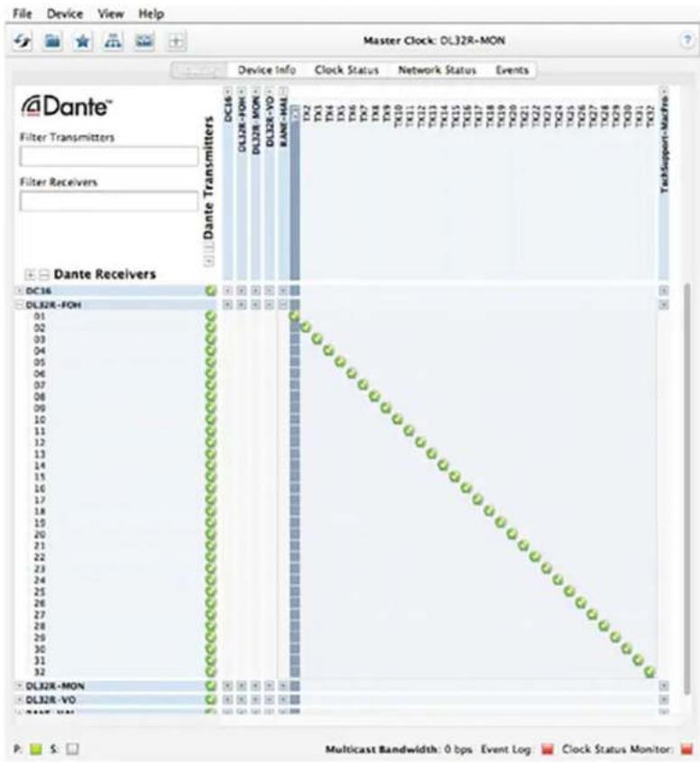
But there is a fourth option, though, which is Dante routing to other recording equipment. There are two steps to follow before you can start recording. The first step is to set up Dante routing via Dante. Most engineers prefer a I-to-I setup. In other words, Dante I to Mic Pre I, Dante 2 to Mic Pre 2, etc. See below for a screenshot of what this would look like in Dante.
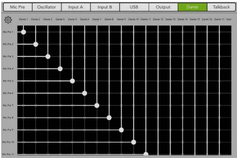
The second step is to set up Dante routing via Master Fader [Tools > I/O Patch > Dante]. We already set up Dante with a I-to-I setup, so we need to do the same in Master Fader. See below.
scatter
| Mic Pre | Oscillator | Input A | Input B | USB | Output | Dante | Talkback | |---|---|---|---|---|---|---|---| | Mic Pre 1 | | | | | | | | | Mic Pre 2 | | | | | | | | | Mic Pre 3 | | | | | | | | | Mic Pre 4 | | | | | | | | | Mic Pre 5 | | | | | | | | | Mic Pre 6 | | | | | | | | | Mic Pre 7 | | | | | | | | | Mic Pre 8 | | | | | | | | | Mic Pre 9 | | | | | | | | | Mic Pre 10 | | | | | | | | | Mic Pre 11 | | | | | | | |
All Dante to Mic Pre settings are patched, but a single screen shot showing all is impossible.
Basically what we're doing here is sending outputs I-28 of the DL32R – since 29-32 have already been auto-routed – to whatever your routing choice may be... a Dante Virtual Sound Card, for example.
Chapter 4: DC16 Front and Rear Panels
Front Panel Introduction
From left to right, the front panel of each DC16 is outfitted with a phones jack and... that's it! Let's take a look at the phones jack then move on to the rear panel before it's too late.
Phones Jack
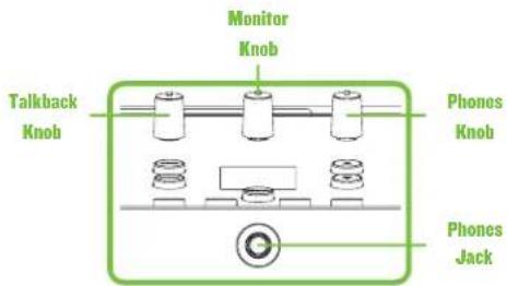
This I/4" TRS connector supplies the output to stereo headphones. The volume is controlled with the Phones knob located in the upper-right corner of the top panel of the DC16. The signals sent to this jack are the same as the signals sent to the monitor outputs, described on the following page.
The phones output follows standard conventions:
Tip = Left channel
Ring = Right channel
Sleeve = Ground


Warning: The headphone amp is loud and could cause permanent hearing damage. Even intermediate levels may be painfully loud with some headphones. BE CAREFUL! Always turn the phones knob all the way down before connecting headphones, soloing a channel or doing anything new that may affect the headphone volume. Then turn it up slowly as you listen carefully.
As mentioned (and seen) above, the phones level is controlled by the phones knob. Because the phones knob is located on the top panel of DC16, it will be described in more detail in that section.

A headphones logo with an arrow pointing down (as seen to the left) is located near the bottom-right of the top panel underneath the bank / channel arrow buttons. This is to help indicate where the phones jack is located. I keep making suggestions (see below left), but they never end up using them. No need to fret, though; I'll continue to feed 'em my ideas. I'm sure you like them as much as I do... right?!
Rear Panel Introduction
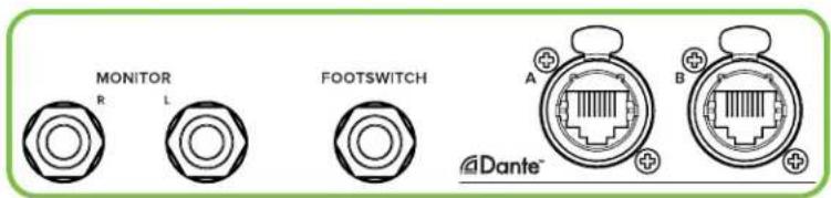
From left to right, the rear panel of each DCIG is outfitted with a talkback mic input jack, an I/8" stereo input jack, I/4" L/R monitor output jacks, a I/4" footswitch jack, two Dante I/O jacks, a force update button, a network connector for Wi-Fi control, three USB ports for tablet control and charging, a power connector and power switch and last but not least... a 4-pin input jack for a lamp. Let's take a look at each of these features, starting on the left with the talkback mic input jack and I/8" stereo in jack, then work our way right.
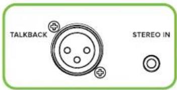
Talkback Mic Input
This XLR connector may accept a balanced external mic for talkback. It is wired as follows, according to standards specified by the AES (Audio Engineering Society).
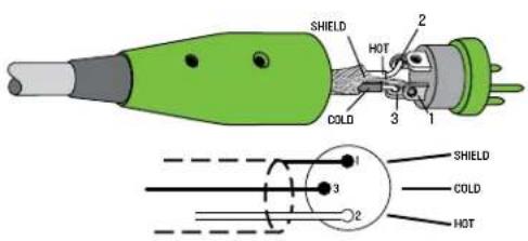
XLR Balanced Wiring: Pin 1 = Shield (ground) Pin 2 = Positive (+ or hot) Pin 3 = Negative (- or cold)

Talkback may be easily engaged and disengaged when utilizing a footswitch that's connected to the 1/4" input on the rear panel. More information on the next page [1/4" Footswitch Jack].
The talkback level is controlled by the Talkback knob as seen on the previous page. Because the talkback knob is located on the top panel of DC16, it will be described in more detail in that section.
1/8" Stereo In Jack
The stereo input may accept an I/8" line-level signal from a smartphone, MP3 player, computer, or other signal source.
This input was designed not to clip with any common 1/8" source which is why a gain knob is not needed for this input.
1/4" Monitor L/R Outputs
These 1/4" connectors allow you to send balanced or unbalanced line-level outputs to a floor monitor, wireless in-ear monitor system or a pair of control room studio monitors. These could either be passive studio monitors powered by an external amplifier, or powered studio monitors with built-in power amplifiers.
To connect balanced lines to these inputs, use a 1/4" Tip-Ring-Sleeve (TRS) plug. "TRS" stands for Tip-Ring-Sleeve, the three connection points available on a stereo 1/4" or balanced phone jack or plug. TRS jacks and plugs are used for balanced signals and stereo headphones and are wired as follows:
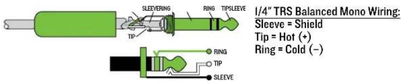
To connect unbalanced lines to these inputs, use a 1/4" mono (TS) phone plug, wired as follows:


Unbalanced cables can be noisy. If the studio monitors support balanced cables, we highly recommend using those instead of unbalanced cables.

The monitor level is controlled by the monitor knob as seen a couple pages back. Because the monitor knob is located on the top panel of DC16, it will be described in more detail in that section.
1/4" Footswitch Jack
This I/4" TRS connector is where to connect your favorite footswitch. This allows you to easily enable or disable talkback at will. This is a momentary switch meaning that talkback is always on when the footswitch is engaged and held. Additionally, the talkback button on the top panel of the DC16 will illuminate green indicating just how engaged it is. Talkback will disengage when pressure on the footswitch is released. Any one-button on / off footswitch will work.

You have options! As mentioned above, there is a talkback button on the top panel of the DC16 in the Mix Selector section. Like the footswitch, it, too, is momentary. Additionally, talkback may be enabled / disabled via Master Fader's Quick Access Panel.
Dante A / B
The dual Dante ports allow daisy chaining and the dedicated Wi-Fi control port eliminates the need for an Ethernet switch in many situations.
Here, you should use a shielded network cable that is CAT5E (or better) to connect DC16 to the DL32R. This allows for control, monitoring, talkback and more. Additionally, the Dante ports may also be used to connect to other Dante-enabled audio networks. As such, it is a perfect solution for connecting to a Dante-enabled loudspeaker system.
Additional information about Dante was discussed previously on pages 10-16.
-Force Update Button


The force update button is conveniently located between the Dante A / B and Network connectors. In a perfect world, this button would just sit there without a care in the world, umbrella drink in hand, beach, surf and sun on a daily basis. Continuing with this “perfect world” scenario, I would be right by the force update button (also without a care in the world, umbrella drink in hand, beach, surf and sun on a daily basis). In all likelihood, though, this button will live his / her dream out, while the rest of us can only dream of such a life.
DCI6 and Master Fader app do a great job at letting you know when either (or both) the software and firmware need updating, but this button here forces a complete firmware update if the need ever arrives.
Here's how to force a firmware update: first, turn the mixer off. Now, with a bent paperclip, poke the force update button, then power up the DC16 with the button depressed. The mixer will boot and you will be prompted with an update bubble the next time an iPad with the Master Fader app is connected to a wired control port.

Now that you know how to force an update, here's a friendly reminder that you should let the button remain peaceful, calm and tranquil, only forcing a firmware update if instructed by Tech Support. Thank you for listening!
Save any current show to your tablet before forcing an update or you may lose it. The show and your sanity!
Wi-Fi Control
natural_image
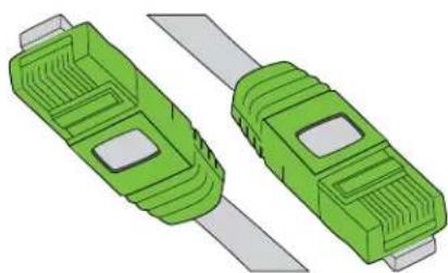
Two green USB connectors with slots and metallic blades, shown side by side (no text or symbols)The DC16 comes equipped with a single network port for control. The purpose in life of this 100 Mb network connector is to connect the DC16 to a Wi-Fi router via CAT5 Ethernet cable, thus enabling wireless control.
Plug one end of the CAT5 Ethernet cable into the mixer's network connector and the other end of the CAT5 Ethernet cable into a LAN port on the router, NOT a WAN port. Most routers allow the use of either a straight-wired cable or crossover cable, but if you have a choice, a straight-wired CAT5 Ethernet cable is the way to go to ensure smooth operation with any router.

Complete directions for setting up the router may be found in the Master Fader Reference Guide.
Tablet Control and Charging USB Inputs
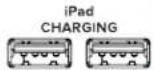
Connect up to three tablets on the DC16's Smart Bridge using standard USB to lightning cables for charging and control. The two USB-A iPad Charging ports are simply for keeping tablets charged while on the Smart Bridge. The single USB-A iPad Control port, on the other hand, serves a couple of purposes. First, as the name states, whatever iPad is connected to this port has full control of DC16. Moreso, it allows for recording and playback [digital streaming, 2 in / 2 out, 44.1 kHz / 48 kHz, 16-bit, 24-bit].

The iPad Control port does NOT need a Wi-Fi router for operation.
Power Connector
Push the locking multi-pin connector (flat side up) of the power supply into the power connector of the control surface. Push the line cord securely into the power supply and plug the other end into a grounded AC outlet. These are included in the packaging.

Make sure that the AC power is matched to the AC power indicated on the rear panel (below the power connector).

Warning: Disconnecting the plug's ground pin is dangerous. Don't do it!
In fact, it's a bad idea to remove anything from – or add anything to, for that matter – the line cord. Again, don't do it!
![ON OFF POWER LAMP Flat side (with arrows and lines) on top. Push to lock, pull (on outlined area) to unlock and remove. The Power Block Power Switch Press the top of this row of this switch to turn it As a general guide, the followed by the DC16 a As such, the DC16 and the possibility of any tu Technically the DC16 w is powered on first, but received. Lamp Input Jack The 4-pin XLR connect of a I2V gooseneck lam it locks – 'clicks' – in p There is sufficient cur 420 mA] halogen lamp](/content/2026/05/811442/images/14177877df60eae1461e4a3694915da120c733b2d87b8b9400c77c02634b0f4f.jpg)
Power Switch
Press the top of this rocker switch in to turn the DC16 on and press the bottom of this switch to turn it off.
As a general guide, the Wi-Fi router should be turned on first, then the DL32R followed by the DC16 and external power amplifiers or powered speakers. As such, the DC16 and DL32R should also be turned off last. This will reduce the possibility of any turn-on or turn-off thumps in the PA.
Technically the DC16 will still be able to discover the DL32R even if the DC16 is powered on first, but you might be required to refresh the mixer list the DC16 received.
Lamp Input Jack
The 4-pin XLR connector located next to the power switch allows connection of a I2V gooseneck lamp. Simply line up the pins and holes and push until it locks - 'clicks' - in place.

There is sufficient current provided to allow using high-intensity [5 watt, 420 mA] halogen lamps.
Chapter 5: DC16 Top Panel
Top Panel Introduction
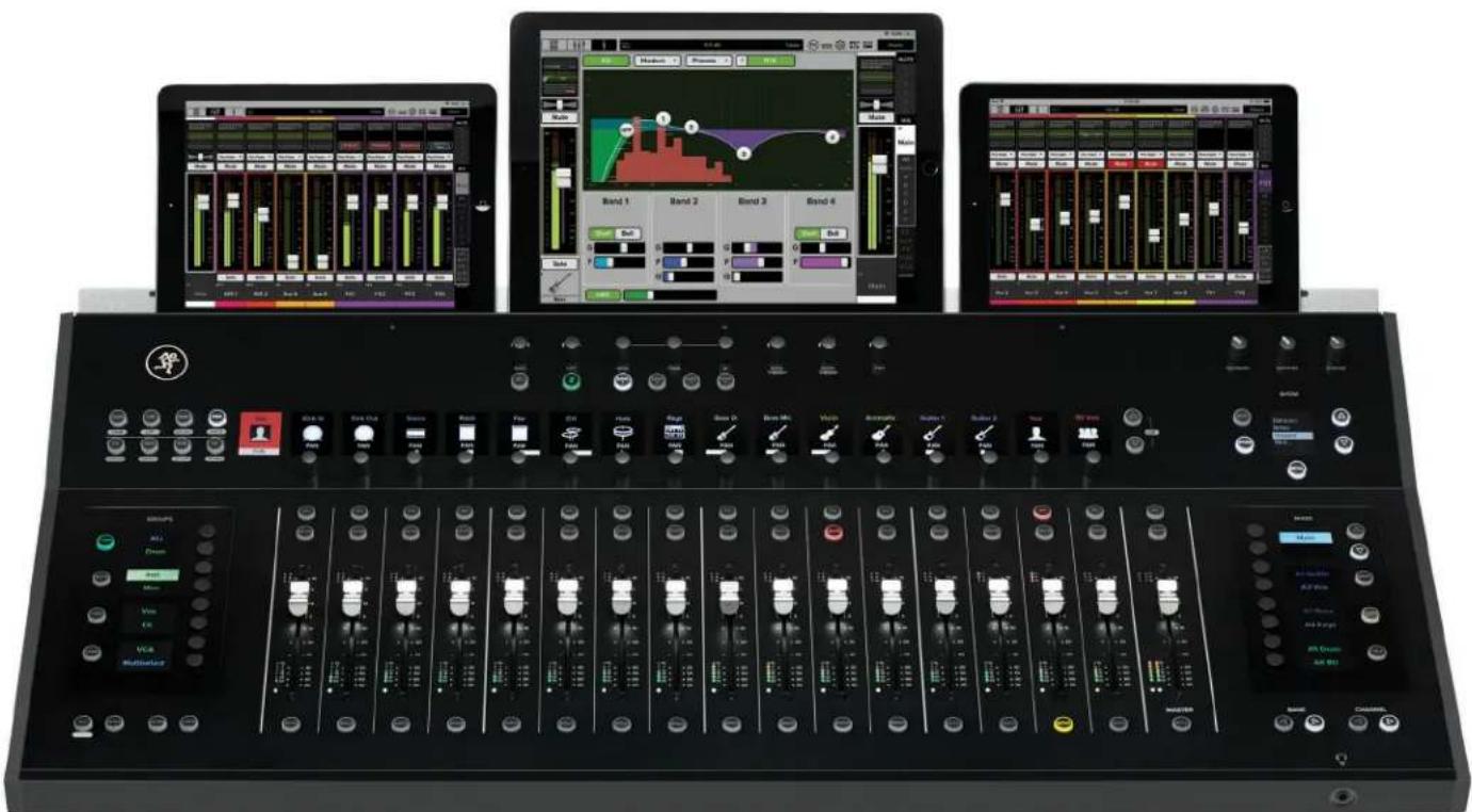
From top to bottom and left to right, the top panel of each DCIG is outfitted with a bunch of knobs, switches, faders, screens, encoders and more. So much more, in fact, that we will call out and describe each one... but not here... and not left-to-right like we did with the front and rear panels.
Rather, what you see below is an outline and order each section will be described. Refer to the pages listed for in-depth commentary and illustrative close-ups of each section.

As a reminder, the information detailed on the following pages is how to use and control the DC16. There is little to no explanation regarding Master Fader. For that, we urge you to read and review the latest Master Fader Reference Guide.
Input Channels / Master Channel - pages 23-24
Channel Screens Overview - pages 25-26
Ranking Group Selector – page 26
Groups Selector - pages 27-36
Fix Selector - pages 37-46
Channel Editing - pages 47-62, 86-94
Fat Channel - pages 63-65
Snapshot Control - pages 66-67
Jnalog Controls - page 68
10odifiers - pages 69-75
mart Bridge - pages 76-85

Input Channels / Master Channel
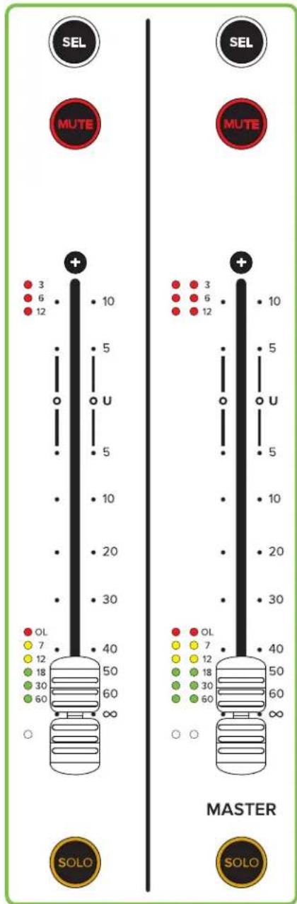
There are a total of 16 input channel strips and one master channel strip on DC16. From top to bottom each strip contains the following:
- SEL (Select) Buttons
A select button does exactly what it sounds like it does. It selects that input or output, readying it for immediate editing purposes.
The selected input or output will be presented in the Selected Channel display in the upper-left corner of DC16 (next to the channel editing buttons), regardless of what bank of channels or output is currently viewed in the remaining I6 ID displays.
As seen to the right, select buttons illuminate white when engaged (although only one input or output may be selected at a time).
This button is also used in conjunction with the ASSIGN button as described on pages 70-71.

- MUTE Buttons
Mute buttons mute - turn off - the signal on the selected input(s) and/or output(s). However, what's muted is dependent on the selected mix. In other words, with LR selected it displays the LR mute for the channel, but with an aux selected it displays either the LR mute or aux mute depending on the setting of "Use LR Mute" for that aux.
Engaging a mute button provides the same result as sliding a fader all the way down.
As seen to the right, mute buttons illuminate red when engaged.
If muted by a VCA or Mute Group, this button's LED will flash on and off.

• 100 mm motorized touch sensitive faders
The input channel faders adjust the level of the associated channel going to the selected mix and the master channel fader adjusts the output level of the selected mix [LR, aux masters, FX master sends, sub outs, VCAs and matrices].
Additionally, as stated in the title, these faders are "touch sensitive". What this means is that the faders have set points as dictated by your fingers (or other conductive material; anyone mixing via toes, perhaps?).
If non-conductive material is used to move the faders – a plastic pen or wooden back scratcher, for example – the faders will return back to their original set points after a few seconds. Furthermore, when a fader is touched / moved, the channel display above that channel will show the current dB level.

While a single fader controls the output level of each output, each output is independent of the others. Once the selected mix has been chosen, move the master fader up and down to make adjustments.
If an FX is selected, the fader controls the master send into the corresponding FX processor.
bar
| System | Value | |--------|-------| | SEL | 10 | | MUTE | 10 | | MASTER | 50 | | MASTER | 60 | | MASTER | ∞ | | MUTE | 12 | | MUTE | 18 | | MUTE | 30 | | MUTE | 60 | | MUTE | ∞ | | OL | 7 | | OL | 12 | | OL | 30 | | OL | ∞ | | MUTE | 7 | | MUTE | 12 | | MUTE | 30 | | MUTE | ∞ | | MUTE | ∞ |
- Gain Reduction LEDs
The input gain reduction LEDs display the channel gain reduction from the gate and compressor, while the output gain reduction LEDs display the amount of gain reduction applied to the output by the compressor / limiter. Output channels do not contain gates.
These LEDs display the sum of the total reduction applied by the gate and compressor [inputs, mono] and compressor / limiter [outputs, stereo].

There are two rows of GR LEDs on the master channel strip and GR is applied equally to the left and right side. However, if the output is mono, only the left side LEDs will illuminate.
As seen above-left and on the previous page, the gain reduction LEDs illuminate red when the signal crosses the values listed next to each LED.
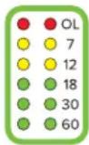
- Level Meter LEDs
The input level meter LEDs display the input signal level to the channel and the output level meter LEDs display the output signal level. The input levels are all before channel processing, while the output levels are post-fader and post-processing. Changes made to the EQ, mute and fader do not affect these meters. These LEDs should remain green with the occasional bump into the yellow zone.

There are two rows of level meter LEDs on the master channel strip. However, if the output is mono, only the left side LEDs will illuminate.
As seen above-left and on the previous page, the level meter LEDs illuminate green, yellow and red when the signal crosses the values listed next to each LED.

- Mix Select LEDs
If they aren't already, the mix select LEDs will very soon be your best friend. That's because these LEDs illuminate the color of the currently selected mix to help identify the mix that the faders are currently feeding. That's it in a nutshell, but let's dig a little deeper before moving on... but not too deep!
For example, by default, these LEDs will illuminate white when Main LR is selected, magenta for aux 1/2, red for aux 3/4, orange for aux 5/6, etc., blue for subs, green for VCAs, purple for FX and white for matrices. Of course, if you change the colors for these output mixes, the Mix Select LEDs will reflect this.
The mix select LEDs will help exponentially when switching between inputs, different banks of channels, the masters section, when mute and view groups are in play and more.
There is an entire section dedicated to the Mix Selector. You'll find it on pages 37-46.
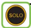
SOLO Buttons
Solo offers the opportunity to audition channel(s) [input channel strips] and/or the selected mix [output / master channel strip] before they are added to the mix. Whenever a channel's solo button is engaged, only the soloed channel(s) may be heard in the monitor bus.
As seen above-left and on the previous page, solo buttons illuminate orange when engaged.

If soloed by a VCA Group, this button's LED will flash on and off.
Channel Screens Overview
Lying horizontally above the fader strips are 17 channel displays and two Channel Editing Page buttons. The channel display on the far left is the selected channel display and does not have an encoder below it; the remaining 16 channel displays have encoders for parameter control. See below for image and descriptions.

flowchart
graph LR
    A["Ch 1"] --> B["Gain"]
    C["Ch 2"] --> D["GAIN GAIN GAIN GAIN GAIN GAIN GAIN GAIN GAIN GAIN GAIN GAIN GAIN GAIN GAIN GAIN GAIN GAIN GAIN GAIN GAIN GAIN GAIN GAIN GAIN GAIN GAIN GAIN GAIN GAIN GAIN GAIN GAIN GAIN GAIN GAIN GAIN GAIN GAIN GAIN GAIN GAIN GAIN GAIN GAIN GAIN GAIN GAIN GAIN GAIN GAIN"]
    B --> E["Selected Channel Display"]
    D --> F["Channel Displays and Encoders"]
    F --> G["Editing Page Buttons"]
• Channel Displays and Encoders
The channel display on the far left (and to the right of the channel editing buttons) is the selected channel display.
As the name dictates, It will always display the selected channel input or output regardless of what bank of channels or outputs the other 16 channel screens are displaying. This way you're able to swiftly and easily make updates via the Fat Channel (described later) whether or not the channel is even displayed in the current bank of 16. The remaining 16 channel screen displays show the current channels under control by the fader, mute and solo controls and the editing controls for the encoders below them.

flowchart
graph LR
    A["Channel System Name"] --> B["Tom"]
    C["Edit Mode Name"] --> D["GAIN"]
    E["Parameter Value"] --> F["Kick"]
    E --> G["S Top"]
    E --> H["S Btm"]
    E --> I["HiHat"]
    E --> J["Tom"]
    K["Parameter Name"] --> L["GAIN"]
    M["Parameter Graphic"] --> N["GAIN"]
    O["Channel Encoder"] --> P["GAIN"]
    style A fill:#FFD700,stroke:#333
    style C fill:#FFD700,stroke:#333
    style E fill:#FFD700,stroke:#333
    style K fill:#FFD700,stroke:#333
    style M fill:#FFD700,stroke:#333
    style O fill:#FFD700,stroke:#333
    style B fill:#FF6347,stroke:#333
    style D fill:#FF6347,stroke:#333
    style F fill:#FF6347,stroke:#333
    style G fill:#FF6347,stroke:#333
    style H fill:#FF6347,stroke:#333
    style I fill:#FF6347,stroke:#333
    style J fill:#FF6347,stroke:#333
As mentioned (and seen) above, there are two primary functions of the channel displays and encoders:
(I) To display each channel's ID information. Notice how each display contains the CHANNEL icon (or image), system name and user name (in your selected colors no less!) and PARAMETER name, and graphic. The parameter value is also displayed when being updated [Ch. 3 gain level (27 dB) in this example].
(2) To edit the parameters via the encoders. The encoders may be rotated to raise and lower values depending on what parameter has been chosen. These encoders may also be pushed to turn certain functions on and off or to make a selection from a list of choices.
In the example above, the Tom drum channel has been selected. From this view alone you're able to utilize the Fat Channel to update the tom's EQ, dynamics and more. If used in conjunction with the channel editing buttons (also described later), all of these channels parameters may be accessed and changed on the fly. In this case, the gain has been selected meaning that rotating the encoder raises and lowers the channel's gains (or digital trim if the input is USB or Dante).
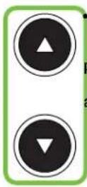
Editing Page Buttons
On the far right of the channel displays strip are two editing page buttons with one arrow pointing up and the other pointing down. These are for displaying additional parameters. For example, parametric EQ has a TON of parameters that may be edited, but there are only 16 channel displays with encoders. Simply push these buttons to view the other available parameters.
These button LEDs are always illuminated when they are available for use. If they're not illuminated, all parameters are displayed and awaiting your changes.
Banking Group Selector
In the lower right corner of DC16 (below the Mix Selector) are four buttons that make up the Banking Group. As seen below, two buttons are for switching banks and two are for switching channels.

Bank / Channel
- BANK Buttons
These buttons shift the currently shown channels, returns, FX, subs, VCAs OR masters left or right in groups of 16.
- CHANNEL Buttons
These buttons shift the currently shown channels, returns, FX, subs, VCAs OR masters left or right one at a time.
Below are a couple of notes regarding bank and channel shifting that you should be aware of...

Banking and channel shifting only works when there are more than 16 channels in the selected view group (including "All").

LED status: The banking and channel button LEDs are always illuminated when they are available for use. If the button LEDs are not illuminated, then the DC16 is banked as far left or right as far as it can be. There will always be a minimum of two button LEDs illuminated, one bank and one channel.
Groups Selector
The groups selector section – appropriately named "GROUPS" – is located on the left-hand side of DC16 just to the left of the faders. Here is where channel settings, view groups, mute groups, user-assignable controls, context-sensitive editing controls and more are displayed and edited.
Also of notice are the eight unmarked buttons to the right of the groups displays. These are for selecting the corresponding group(s) as indicated in the displays.

VIEW Group Button
View groups allow you to see only the channels that you want to view, hiding the rest. This improves organization and allows for faster navigation.
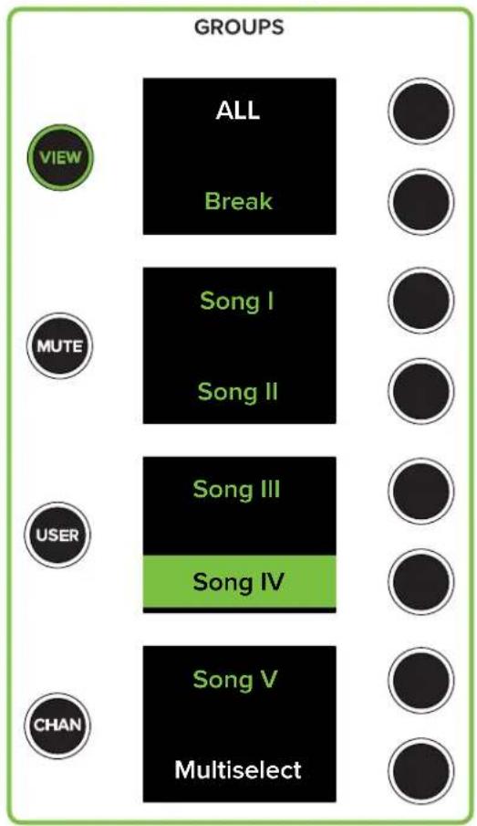
Pressing the VIEW button will present all view groups in each of the four displays as noted below. Additionally, the view groups button LED illuminates green when engaged and the text of view groups A-F are presented in view group green.
Default View Groups Select

flowchart
graph TD
    A["View Group Button"] --> B["VIEW"]
    C["Mute Group Button"] --> D["MUTE"]
    E["User Button"] --> F["USER"]
    G["Channel Button"] --> H["CHAN"]
    B --> I["ALL"]
    D --> J["B"]
    F --> K["D"]
    H --> L["F"]
    I --> M["ALL"]
    J --> N["View Group A"]
    K --> O["View Group B"]
    L --> P["View Group C"]
    M --> Q["View Group D"]
    N --> R["View Group E"]
    O --> S["View Group F"]
    P --> T["Multiselect"]
    Q --> U["Multiselect"]
    R --> V["Multiselect"]
    S --> W["Multiselect"]
To select a view group, press the button to the right of said view group presented in the display. The view group will be highlighted in view group green.
If multiselect is ON - highlighted white with black text - multiple view groups may be selected simultaneously (except "ALL").
As seen below, if multiselect is OFF – not highlighted, white text – then only a single view group may be selected at a time.
Customized View Groups Select
Additionally, channels may be assigned (and unassigned) to view groups simply by utilizing the assign modifier button. More details in the "Modifiers" section on pages 69-75.
While view groups may be displayed and selected via DC16, the names will still need to be created using Master Fader.
Additional information regarding view groups is documented quite thoroughly in the Master Fader Reference Guide.
MUTE Group Button
Mute groups allow you to quickly mute (and unmute) multiple channels and/or outputs. There are a multitude of possibilities in which to assign and enable mute groups: productions featuring a rotating cast of musicians, theater productions, a house of worship and more. It is also great for muting all inputs during song breaks or in-between sets.
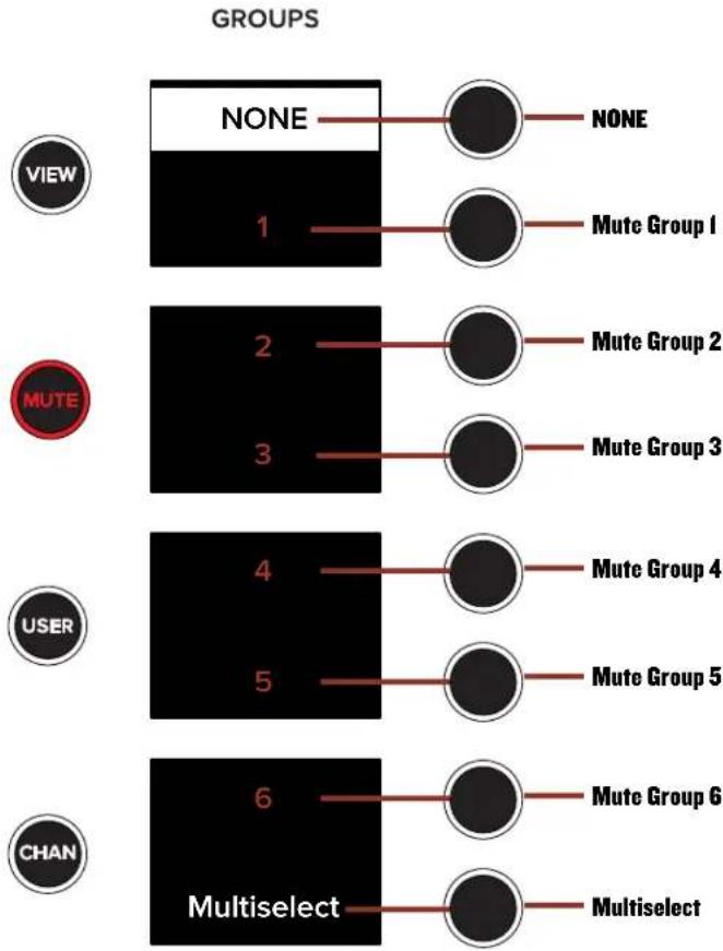
Pressing the MUTE button will present all mute groups in each of the four displays as noted below. Additionally, the mute groups button LED illuminates red when engaged and the text of mute groups I-6 are presented in mute group red (aka oxblood red).
Default Mute Groups Select
flowchart
graph LR
    A["VIEW"] --> B["NONE"]
    B --> C["1"]
    C --> D["Mute Group 1"]
    D --> E["NONE"]
    F["MUTE"] --> G["2"]
    G --> H["3"]
    H --> I["Mute Group 2"]
    I --> J["None"]
    K["USER"] --> L["4"]
    L --> M["5"]
    M --> N["Mute Group 3"]
    N --> O["None"]
    P["CHAN"] --> Q["6"]
    Q --> R["Multiselect"]
    R --> S["Mute Group 4"]
    S --> T["None"]
    U["Mute Group 5"] --> V["None"]
    W["Mute Group 6"] --> X["None"]
    Y["Multiselect"] --> Z["None"]
To select a mute group, press the button to the right of said mute group presented in the display. The mute group will be highlighted in oxblood red.
As seen below, if multiselect is ON - highlighted white with black text - multiple view groups may be selected simultaneously (except "NONE").
If multiselect is OFF - not highlighted, white text - then only a single mute group may be selected at a time.
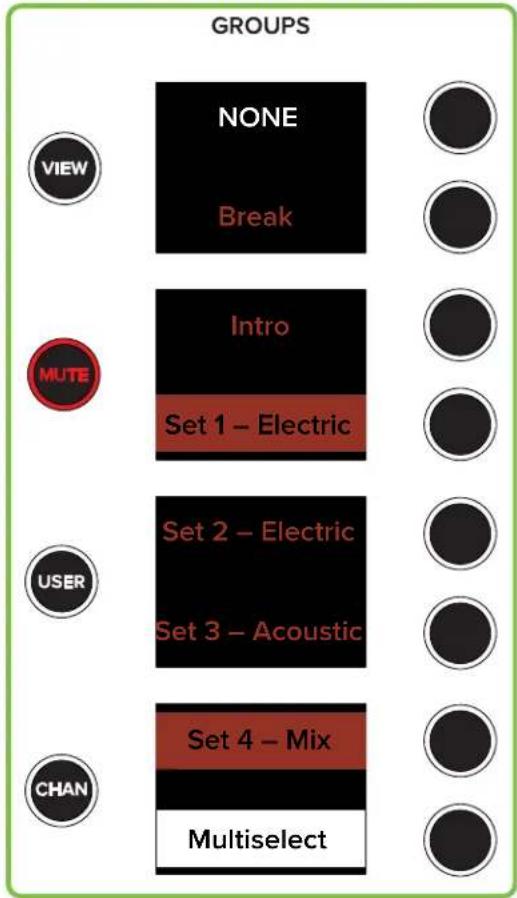
Additionally, channels may be assigned (and unassigned) to mute groups simply by utilizing the assign modifier button. More details in the "Modifiers" section.

While mute groups may be displayed and selected via DC16, the names will still need to be created using Master Fader.
Additional information regarding mute groups is documented quite thoroughly in the Master Fader Reference Guide.
Customized Mute Groups Select

USER Button
The USER button displays eight user-assignable buttons. The default assigned buttons are displayed below, but feel free to select and load whichever presets and parameters that you want (with a couple of minor restrictions, detailed shortly). Press the USER button to see something similar to what's displayed below:
Default User Groups Select

flowchart
graph TD
    A["MUTE LR"] --> B["MUTE LR"]
    C["USER BUTTON 2"] --> D["USER BUTTON 2"]
    E["MUTE FX 1"] --> F["MUTE FX 1"]
    G["MUTE FX 2"] --> H["MUTE FX 2"]
    I["MUTE FX 3"] --> J["MUTE FX 3"]
    K["MUTE FX 4"] --> L["MUTE FX 4"]
    M["CHAN"] --> N["USER BUTTON 7"]
    O["VIEW"] --> P["MUTE LR"]
Let's try something right out of the gate. Tap the mute LR button from the groups selector. It is now highlighted in the groups selector. More importantly, check out the main L/R mute button. It's engaged! That's right, you may select up to eight parameters to tie to these buttons for quick access of critical functions, all without having to leave your current view.
Now that you have an idea of what it does, we should take a look at how to assign parameters to these buttons.
Step I - Tap the USER button. You should totally already be here, but in case you haven't already, this is where it all begins. The USER button LED will illuminate white, confirming just how on it is.
Assign Mode: USER Btn 1
USER Control: MUTE LR
Step 2 – Press and hold the ASGN button down while simultaneously pressing one of the unmarked buttons on the group selector. This selects which button will have the parameter you choose associated with it. Release the buttons. The ASGN button's LED should be flashing red and the selected channel display will show the current input or output parameter.
Step 3 - Press the channel editing button of the parameter that you want locked to a user button. This includes HPF / LPF, send / delay, EQ, GEQ, etc. We'll do eight separate ones starting with HPF. Tap the HPF button.
Assign Mode: USER Btn 1
USER Control: HPF Ch13
Step 4 – Press the encoder of a channel whose parameter you want locked to a user button. We decided to go with the saxophone on channel I3, so press that channel's encoder. It is now locked to user button 1, replacing mute LR.
GROUPS
Step 5 - Press the ASGN button again to exit assign mode. Note that you will still be in USER mode, but only because that particular group selector button is still engaged. It is also the only way to make these quick changes. They are assigned via the USER button!

HPF Brass



Step 6 – Press the unmarked button next to HPF BRASS several times. You will notice that the text is highlighted when the parameter is engaged (see to the right) and just text alone when the parameter is disengaged (see below-left).

MUTE FX 1
MUTE FX 2
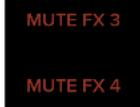


The only time this is not true is when an FX tap delay is assigned to a user button. What happens in this case is that the tap tempo is displayed and flashes at the current rate. Simply tap this user button at the rate you want the tap tempo. A tap delay has been added to user group button 8, below left.

MUTE FX 3
MUTE FX 4


Step 7 – You're done! Load up the remaining seven buttons the same way you just did. We will do a variety of selections to show just how powerful this feature truly is.


As powerful as it is, the only parameter values that may be changed are on/off, tap delays and the like. In other words, encoder turns, fader movements and the like can not be added as a parameter change to a user button.
As you can see to the left, we assigned all eight user buttons to a different input or output:

bup Button 1 - Channel I3 (brass) HPF on/off bup Button 2 - Aux 1-2 (monitors) LPF on/off
• User Group Button 3 – Channel II-12 (keyboards) sends on/off pup Button 4 – Main LR (PA) delay on/off
- User group Button 5 - Channel I (kick) EQ on/off
- User Group Button 6 – Main LR (PA) GEO on/off


The following is a list of parameters that may be assigned to user buttons:

parameters -HPF/LPF, delay, EQ/GEQ, gate/comp per channel and/or mix
per channel, mix and/or VCA ay - mono and/or L/R
- \$Eh(ect) - per channel and/or mix - Recall snapshot - per snapshot number


- Mute group masters – enable/disable per mute group and none - View group masters – enable/disable per view group and all and/or auto
One final thing we should discuss. How to unassign a parameter from a user button. There are two ways, really:
(I) Instead of unassigning a parameter from a user button, simply assign a different parameter to that user button. This is accomplished by following the directions we just described.
(2) Press and hold the ASGN button down while also pressing and holding the user button you want cleared for two seconds. That will clear the parameter from the chosen user button.

Make sure to press the ASGN button again so it is no longer flashing. Otherwise, you may end up assigning another parameter to that user button since it is still in assign mode!

CHAN(nel) Button
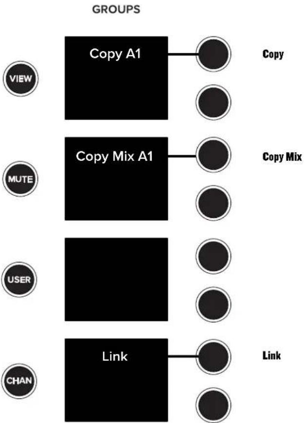
Tapping the CHAN(nel) button allows you to quickly copy-and-paste parameters and presets from one channel (and/or output) to another. Additionally, channel inputs and outputs may be linked (and unlinked) via the CHAN(nel) button. The default CHAN(nel) view is displayed to the right. The currently selected input / output will be displayed in the "Copy" spot.
It's the 21st century and seemingly everyone has been using copy-and-paste for a multitude of things... and you can with DCI6, as well. Here you're able to copy the settings of one input channel and paste those same settings onto another input channel. Copy-and-paste is a fast and convenient way to send the settings from one channel to another and tweak to your liking. It's a great starting point!
Enough with the talk, just how do you copy-and-paste via DC16?! It is super-easy:
Step 1 - Tap the CHAN(nel) button.
Step 2 – Select the channel you want to copy. For this example, we're selecting channel 4 (Tom).
Step 3 - Tap the Copy Ch4 button. The channel screens will look something like this:
Chan Groups Select
flowchart
graph TD
    A["VIEW"] --> B["Copy A1"]
    B --> C["Copy"]
    D["MUTE"] --> E["Copy Mix A1"]
    E --> F["Copy"]
    G["USER"] --> H["Link"]
    H --> I["Link"]
    J["CHAN"] --> K["Link"]





Step 4 – Tap the Do it! encoder to copy channel 4's information or Cancel or Exit to cancel the action and exit out of copy-and-paste.
Step 5 - Select the channel you want to paste to. For this example, we're selecting channel 30.
Step 6 – Notice how the ability to paste via the groups select is now available (visual to the right). Tap the Paste button.
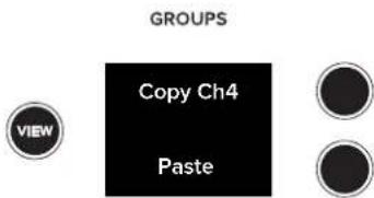
Step 7 - You will be presented with another prompt on the channel screens. Tap the Do it! encoder to paste channel 4's information onto channel 30 or Cancel or Exit to cancel the action and exit out of copy-and-paste.

Step 8 – Upon returning to the channel screens, you should notice that channel 30 now has (almost) all of the same attributes as that of channel 4.
The “pasted” channel will take on most of the attributes [name, icon, color, EQ settings, gate and compressor settings] of the “copied” channel. But there are a few characteristics that are not pasted and remain independent. This includes mic pre gain, 48V, source, digital trim, pan and fader level and any assignments / routing. This is useful in multiple situations. For example, a typical setup might have one guitar panned hard left and the other panned hard right. Or perhaps if they’re using different amps
(which is highly likely), then gain, trim and fader levels would differ.
That's not all! The settings of one output may be copied-and-pasted onto another output. The directions to do so are fairly similar to that of copying-and-pasting input channels. However, instead of selecting a channel to copy, select an output from the mix. [Be sure to select the output from the mix selector, as well as the select button at the top of the master fader.] Next, you will be given the opportunity to Copy or Copy Mix.
Copy-and-paste will paste everything except pan and fader level, aux / FX send configuration and any assignments / routing. This is useful in multiple situations. Everyone in the band is different and will have different needs. Levels will certainly differ and aux sends could be configured, assigned and routed differently. As such, these parameters will remain independent. However, with copy mix and paste mix, the pan and fader adjustments are carried over.

So... what does this mean? Simply put, if you already have multiple channels dialed in and the FOH sounds great, setting up monitors for the band is a cinch. Copy-and-paste the mix from one output to another output. It's a great starting point rather than starting out from scratch... right?!
After tapping Copy or Copy Mix, the channel screens will ask if you want to copy / copy mix the currently selected output. Tap the Do it! encoder to continue. Next, select the output you want to paste / paste mix to. Almost there! Simply tap the paste or paste mix button on the groups selector followed by tapping the Do it! encoder. Boom, done!
As mentioned at the top of the hour, the CHAN(nel) button also allows you to link two adjoining mono input channels together into a single stereo channel strip. This is ideal for stereo input sources such as keyboards, submixer outputs, vocal processors and more (although we will link the just copy-and-pasted tom drum on channel 30; stay tuned!). When linked, the level control, EQ, gate/compressor, etc. are adjusted with a single set of controls!
Linking channels is just as easy as copy-and-paste, if not easier!
Step I - Tap the CHAN(nel) button.
Step 2 – Select the channel you want to link. For this example, we're selecting channel 30 (Tom).
Step 3 - Tap the Link button. The channel screens will look something like this:

Step 4 - Tap the Do it! encoder to link channel 30 over channel 29 or Cancel or Exit to cancel the action and exit out of link.
Step 5 – Upon returning to the channel screens, you should notice that channels 29-30 are now linked as a stereo channel.
Step 6 - Follow the same steps outlined above to unlink channels.

Odd-numbered channels will link to the next (even-numbered) channel [e.g. 1-2, 3-4, etc], while even-numbered channels will link to the previous (odd-numbered) channel [e.g. 10-9, 12-11, etc].

The new linked channel will take on all of the attributes [EQ settings, gate and compressor settings, FX, etc.] of the originally selected channel. In other words, if you link channel I over 2, the resulting stereo channel will take on all of the settings of channel I. However, if you link channel 2 over channel I, the resulting stereo channel will take on all of the settings of channel 2.
Mic pre gain, 48V, source and digital trim are not linked and independent. This is useful in multiple situations. Stereo overhead mics on a drum set require different gain levels to adjust for crash versus ride, for one example. Or perhaps two mics are in front of a guitar cabinet, one condenser and one dynamic. Here you would be able to enable 48v on one, leaving it off for the other, even though the channel is linked.
Are you more interested in linking adjoining outputs? We have you covered there, as well! The directions to do so are fairly similar to that of linking input channels. However, instead of selecting a channel to link, select an output from the mix.
The next step is to tap the Link button (on the group selectors). The channel screens will ask if you want to link the currently selected output over the adjacent output. Tap the Do it! encoder to continue. The outputs are now linked!

Odd-numbered outputs will link to the next (even-numbered) output [I-2, 3-4, 5-6, etc.], while even-numbered outputs will link to the previous (odd-numbered) output [6-5, 4-3, 2-1, etc.].

The linked over output will take on all of the attributes [graphic EQ settings, output compressor/limiter settings, aux send output routing, etc.] of the initially selected output. In other words, if you link output 1 over output 2, the resulting stereo output will take on all of the settings of output 1. However, if you link output 2 over output 1, the resulting stereo output will take on all of the settings of output 2.

Quick Tip: now that you're a rock star when it comes to linking and unlinking inputs and outputs, do you want to know an even easier way to link and unlink them? Of course you do! Simply press and hold an input's (or output's) SEL(ect) button. After a couple of seconds, you will see the same prompts as listed earlier. Follow the steps to link / unlink without having to enter CHAN(nel) mode!

A final – but no less important! – note about linked input channels. As you may have noticed, only the parameters on the left (odd) side of the linked channel are in view and may be updated. Don't fret! There is an easy way to update the parameters on the right (even) side of linked channels, too. Simply hold down the ALT button while adjusting the parameters. While mono input channels display "gain" on the channel displays (for example), linked channels will display "left gain". When the ALT button
is engaged, though, this will change to "right gain". The parameters that may be accessed and updated are gain, trim, 48v, polarity and output matrix sends.
Mix Selector
The mix selector section – appropriately named "MIXES" – is located on the right-hand side of DCIG just to the right of the faders. This is the place to select between output mixes, cycle through the displayed outputs, display output masters, clear all engaged solos and engage the talkback mic.
Also of notice are the eight unmarked buttons to the left of the mix displays. These are for selecting the corresponding output(s) as indicated in the displays.
Now, the mix selector section already displays a lot of information even before any buttons are pushed, so let's discuss that first. Then we can get into the specifics of each button's function.
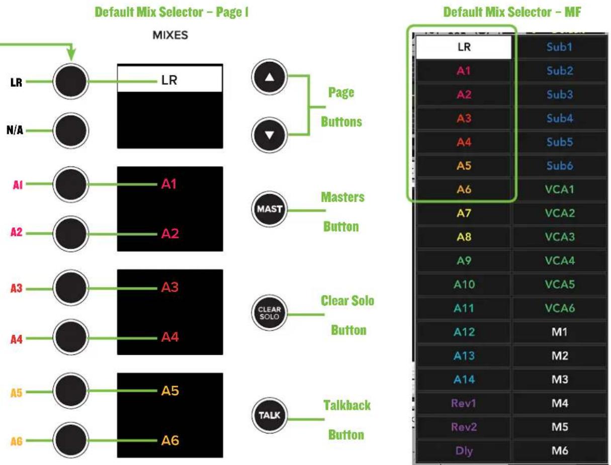
The DC16's mix selector (below left) nearly mirrors that of Master Fader's mix selector (below right).
This is the top of the mix selector, the default. You may use the (down arrow) page button to view and select from other mixes.
Additional examples of the mix selector – default and customized! – are on display over the next few pages.
flowchart
Diagram comparing Default Mix Selector for Page I and MF, showing MIXES and MAST button configurations with labeled buttons like LR, A1–A6, and Clear Solo.As mentioned previously, you need to use the page buttons in order to view and select from other mixes. That said, let's take a quick look at a description and other pertinent notes of the page buttons.

Page Buttons
These buttons shift the currently shown MIXES groups (mentioned on the previous page) up or down.
LED status: The arrow button LEDs are always illuminated when they are available for use. If the button LEDs are not illuminated, then the DC16 is at the very top or very bottom of the mixes list (or in masters mode in which case neither arrow button LED will illuminate). There will always be a minimum of one arrow button LED illuminated when in mixes mode.

While mixes may be displayed and selected via DC16, the names will still need to be created using Master Fader.

If the MAST button is engaged [MAST button LED illuminates white], then you are out of MIXES mode and in MASTERS mode. For now let's stay in MIXES mode. We'll get into MASTERS soon (pages 44-45).
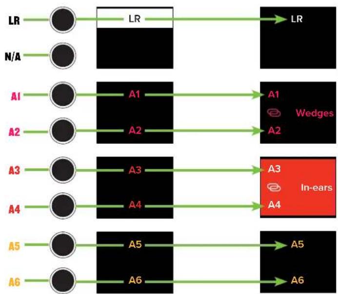
As seen below, page 1 of the mixes displays LR and AI-A6. This customization is relatively simple, as the only changes made here are AI-A2 and A3-A4 were linked and named. The LR and A5-A6 and all colors (including AI-A4) were left at their default.
Also of notice is the highlighted A3-A4. Because they're linked, either of the two buttons may be pushed to select this output. On unlinked outputs, each button will select the output next to it; A5 and A6 below, for example.
Go ahead and push each of these buttons. As you do, notice that the mix selector LEDs - located at the bottom of each fader strip - change to the color of the selected output. This lets you know that the channel faders are now controlling the level of that input to the selected output. As such, the master fader now controls the level of the selected output.
Master Fader DC16: LR - A6 [Page 1]

DefaultDefault Customized
flowchart
graph TD
    LR --> LR
    LR --> LR_A1
    LR --> LR_A2
    LR --> LR_A3
    LR --> LR_A4
    LR --> LR_A5
    LR --> LR_A6
    LR --> LR_A1_Wedges
    LR --> LR_A2_Wedges
    LR --> LR_A3_In-ears
    LR --> LR_A4_In-ears
    LR --> LR_A5_In-ears
    LR --> LR_A6_In-ears
    N/A --> A1
    N/A --> A2
    A1 --> A1_Wedges
    A2 --> A2_Wedges
    A3 --> A3_In-ears
    A4 --> A4_In-ears
    A5 --> A5_In-ears
    A6 --> A6_In-ears
After pushing the page down button, the mixes will display A7-A14. This customization is also relatively simple. Here, the only changes made are A7-A12 were linked and named. AI3 and AI4 were also renamed, but left unlinked. All colors were left at their default except A9-A10. In addition to being linked and named, the color of A9-A10 was also changed from it's default green to red.
As mentioned previously, the mix selector LEDs change to the color of the selected output, letting you know that the channel faders now control the level of that input to the selected output. As such, the master fader now controls the level of the selected output. It's the highlighted AII-AI2 in this example.
Master Fader DC16: A7 - A14 [Page 2]

DefaultDefault Customized

flowchart
graph LR
    A7 --> A7
    A8 --> A8
    A9 --> A9
    A10 --> A10
    A11 --> A11
    A12 --> A12
    A13 --> A13
    A14 --> A14
    A7 --> A7
    A8 --> A8
    A9 --> A9
    A10 --> A10
    A11 --> A11
    A12 --> A12
    A13 --> A13
    A14 --> A14
    A7 --> Subs
    A8 --> Subs
    A9 --> Front Fill
    A10 --> Front Fill
    A11 --> Side Fill
    A12 --> Side Fill
    A13 --> FF Backup
    A14 --> SF Backup
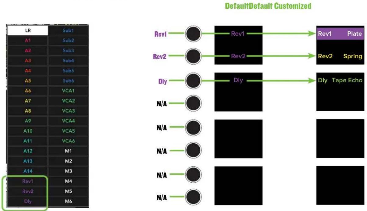
Ok, we're making progress! Push the page down button again to display the FX mixes. The customizations in this example are naming and coloring. As seen below, FX I retains the same purple color, but was renamed to its effect, Plate. FX 2 and FX 3 were renamed to reflect their effects, too - Spring and Tape Echo. However, their colors were changed from their default purple to yellow (FX 2, Spring) and light green (FX, Echo).
The mix selector LEDs change to the color of the selected output, letting you know that the channel faders now control the level of that input to the selected output. As such, the master fader now controls the level of the selected output. It's the highlighted Revl Plate in this example.
Master Fader DC16: FX [Page 3]
flowchart
graph TD
    A["LR"] --> B["Sub1"]
    C["A1"] --> D["Sub2"]
    E["A2"] --> F["Sub3"]
    G["A3"] --> H["Sub4"]
    I["A4"] --> J["Sub5"]
    K["A5"] --> L["Sub6"]
    M["A6"] --> N["VCA1"]
    O["A7"] --> P["VCA2"]
    Q["A8"] --> R["VCA3"]
    S["A9"] --> T["VCA4"]
    U["A10"] --> V["VCA5"]
    W["A11"] --> X["VCA6"]
    Y["A12"] --> Z["M1"]
    AA["A13"] --> AB["M2"]
    AC["A14"] --> AD["M3"]
    AE["Rev1"] --> AF["M4"]
    AG["Rev2"] --> AH["M5"]
    AI["Dly"] --> AJ["M6"]
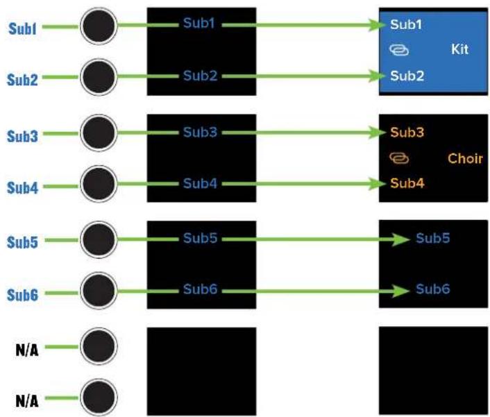
Things start to get a little interesting once we get to the subs. As before, push the page down button to display the subs mixes. The customizations in this example are linking, naming and coloring. As seen below, Subl-Sub4 are linked.
Sub1-Sub2 retains the same default blue color, but was renamed to "Kit". The color of Sub3-Sub4, though, was changed from its default blue to orange. Additionally, it was renamed to "Choir".
The mix selector LEDs change to the color of the selected output, letting you know that the channel faders now control the level of that input to the selected output. As such, the master fader now controls the level of the selected output. It's the highlighted Subl-Sub2 Kit in this example.
When a sub is selected, only the input channels that are associated with the selected sub are displayed. If no channels have been assigned to a sub - Sub5 and Sub6 in this example - then no channels will be displayed.
Master Fader DC16: Subs [Page 4]

DefaultDefault Customized
flowchart
graph TD
    A["Sub1"] --> B["Sub1"]
    C["Sub2"] --> D["Sub2"]
    E["Sub3"] --> F["Sub3"]
    G["Sub4"] --> H["Sub4"]
    I["Sub5"] --> J["Sub5"]
    K["Sub6"] --> L["Sub6"]
    M["N/A"] --> N["N/A"]
    B --> O["Sub1"]
    D --> P["Sub2"]
    F --> Q["Sub3"]
    H --> R["Sub4"]
    J --> S["Sub5"]
    L --> T["Sub6"]
    O --> U["Kit"]
    P --> U
    Q --> V["Choir"]
    R --> V
    S --> W["Sub5"]
    T --> X["Sub6"]
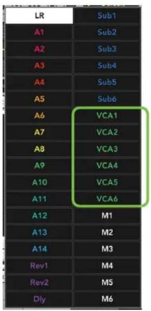
The VCAs work somewhat similarly to that of the subs. Let's see how! Push the page down button to display the VCAs. The customizations in this example are naming and coloring. [VCAs cannot be linked]. VCAI retains the same default green color, but was renamed to "Guitar". The color of VCA2, though, was changed from its default green to orange. Additionally, it was renamed to "Horns". Lastly, the color of VCA3 was changed from its default green to a pinkish-red and renamed "Perc".
The mix selector LEDs change to the color of the selected output, letting you know that the channel faders now control the level of that input to the selected output. As such, the master fader now controls the level of the selected output. It's the highlighted VCA3 Perc in this example.
When a VCA is selected, only the input channels that are controlled by the selected VCA are displayed. If no channels have been assigned to a VCA - VCA4-VCA6 in this example - then no channels will be displayed.
Master Fader DC16: VCAs [Page 5]
DefaultDefault Customized

flowchart
graph LR
    A["VCA1"] --> B["VCA1"]
    C["VCA2"] --> D["VCA2"]
    E["VCA3"] --> F["VCA3"]
    G["VCA4"] --> H["VCA4"]
    I["VCA5"] --> J["VCA5"]
    K["VCA6"] --> L["VCA6"]
    M["N/A"] --> N["Black Box"]
    O["N/A"] --> P["Black Box"]

    Q["VCA1"] --> R["Guitar"]
    S["VCA2"] --> T["Horns"]
    U["VCA3"] --> V["Perc"]
    W["VCA4"] --> X["VCA4"]
    Y["VCA5"] --> Z["VCA5"]
    AA["VCA6"] --> AB["VCA6"]

    AC["N/A"] --> AD["Black Box"]
    AE["N/A"] --> AF["Black Box"]
Last up are the matrices. Push the page down button to display all six. The customizations in this example are naming and coloring. [Matrices may be linked, but aren't in this example]. MI retains the same default white color, but was renamed to "Lobby". The color of M2, though, was changed from its default white to violet. Additionally, it was renamed to "Balcony".
When a matrix is selected, the DC16 will display all subgroups, LR and auxes. The LR and auxes mix selector LEDs are displayed in the color of the selected matrix [default is white], but the subs will be displayed in the color of the sub [default is blue].
The faders now control the level of that subgroup, LR and aux to the selected matrix. As such, the master fader now controls the level of the selected matrix. It's the highlighted MI Lobby in this example.
It's important to remember that these aren't the AUX, LR and Subgroup levels. These are the sends from the associated output to the selected matrix.
Master Fader DC16: Matrices [Page 6]
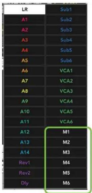
DefaultDefault Customized
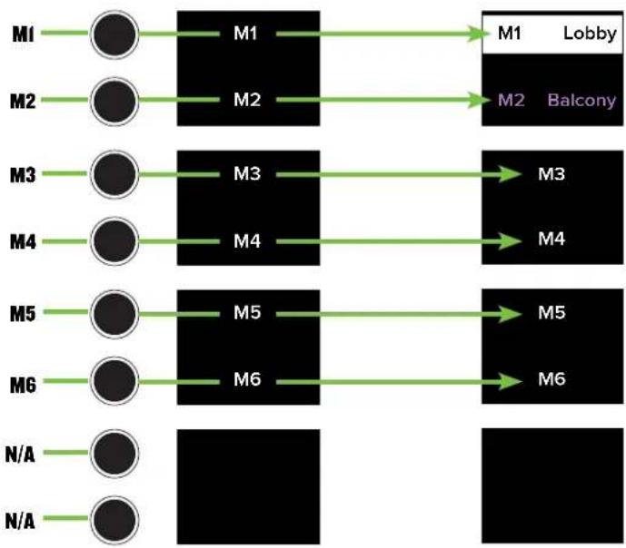
flowchart
graph TD
    M1 --> M1a["M1"] --> M1b["M1"] --> Lobby["Lobby"]
    M2 --> M2a["M2"] --> M2b["M2"] --> Balcony["Balcony"]
    M3 --> M3a["M3"] --> M3b["M3"] --> M4["M4"]
    M4 --> M4a["M4"] --> M4b["M4"]
    M5 --> M5a["M5"] --> M5b["M5"] --> M5c["M5"]
    M6 --> M6a["M6"] --> M6b["M6"] --> M6c["M6"]
    N/A --> N/Aa["N/A"]

MAST(er) Button
If the MAST button is engaged then you are out of MIXES mode and in MASTERS mode... and now we want that!
[For reference, MIXES mode was just described on pages 37-43]. The MAST button is a fast, effective way to switch
between the mix selector and masters. Pressing the MAST button will present all output masters in each of the four
displays as seen below. Additionally, the masters button LED illuminates white when engaged and the text of the masters are all presented in white, as well.
The eight unmarked buttons to the left of the masters displays work similarly to that of the previously mentioned mix selector. Instead of selecting a mix here, though, these are for selecting the corresponding master(s) as indicated in the displays. While you may scroll through six pages of the mix selector, the masters are all presented on a single page so the page up and page down buttons have no function. Also, unlike the mix selector, the masters list can't be "customized".
The DC16's masters selector (below left, examples A and B) nearly mirrors that of Master Fader's masters selector (below right).
DC16 Masters Selector
A - Multiselect OFF B - Multiselect ON
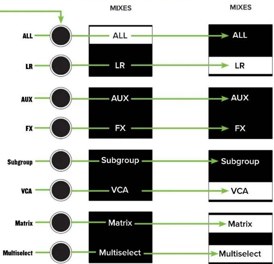
flowchart
graph TD
    A["ALL"] --> B["ALL"]
    C["LR"] --> D["LR"]
    E["AUX"] --> F["AUX"]
    G["FX"] --> H["FX"]
    I["Subgroup"] --> J["Subgroup"]
    K["VCA"] --> L["VCA"]
    M["Matrix"] --> N["Matrix"]
    O["Multiselect"] --> P["Multiselect"]
    B --> Q["ALL"]
    D --> R["LR"]
    F --> S["AUX"]
    H --> T["FX"]
    J --> U["Subgroup"]
    L --> V["VCA"]
    N --> W["Matrix"]
    P --> X["Multiselect"]
    Q --> Y["ALL"]
    R --> Z["LR"]
    S --> AA["AUX"]
    T --> AB["FX"]
    U --> AC["Subgroup"]
    V --> AD["VCA"]
    W --> AE["Matrix"]
    X --> AF["Multiselect"]
Master Fader Masters Selector

To select a master, press the button to the left of said master presented in the display. The text of the selected master will change from white to black. Also, the master will be highlighted in white.
As seen in Example A above, if multiselect is OFF [Default] - not highlighted, white text - then only a single master (including "ALL") may be selected at a time.
As seen in Example B above, if multiselect is ON - highlighted white with black text - multiple masters may be selected simultaneously (except "ALL").
Whereas you're able to raise and lower the inputs and outputs of the selected mix while in MIXES mode, no inputs are available when in MASTERS mode. MASTERS mode is strictly for raising and lowering the selected master [LR, aux, FX, subs, VCAs and/or matrix]. DC16 is smart, only recalling your specific mix selector and masters set up. In other words, any changes made in MASTERS mode will then be evident in MIXES mode upon your return. It would only be fair, then, that the opposite also be true... and it is! Any changes made in MIXES mode will be evident in MASTERS mode, too.
The MAST button has another function, as well. It highlights the current and previously selected mix on the mix deck. An example may be the best way to describe what we're discussing here.
Step I - Let's assume that the you're on the main L/R. The mix deck displays all of the input channels.


Step 2 - Select aux I-2 from the mix selector.
Step 3 - Press the MAST button.
Step 4 - The mix deck now highlights the currently selected mix. Aux I-2 in this example.
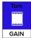




Step 5 – Now select a different output. For this example, we'll simply select the main L/R. This will allow you to edit parameters of the LR Mix from the Masters bank. As you can see below, the current mix (main L/R) is selected, but aux I-2 remains highlighted as a reminder that this was the previously selected output. So whatever mix is currently selected in the mix selector is highlighted when going into the masters view. This is an easy indicator of where you were previously and which mix you'll see when exiting the masters bank.




Press the MAST button to exit masters and return back to the mix selector. Notice that it takes you back to Aux I-2.
LOCKOUT MODE

If you need to leave DC16 – bathroom break, refreshment refill, run to the car for more gear, etc. – but fear that someone will change the settings, fret no more! Lockout allows you to lock DC16, preventing access to all controls until it is unlocked or power cycled.
Lockout mode is enabled (and disabled) by pressing and holding the MAST(er) and CLEAR SOLO buttons for 5 seconds. When enabled, the faders, buttons and encoders will no longer respond to parameter changes. Additionally, the Show Screen will display "Console Locked!"

The meters will still be bouncing when lockout mode is enabled.

CLEAR SOLO Button
The Clear Solo button's LED on DC16 illuminates orange to serve as a reminder that a soloed channel exists somewhere, be it an input or output. This is especially useful when an output is soloed and you switch to adjust a different channel on a different output. Pressing this button will clear all solos on all inputs and outputs, including the ones you can't see.
TALK(back) Button
The talkback button allows you to easily enable or disable talkback at will, routing talkback to all configured destinations. This button's LED illuminates green when pressed, indicating just how engaged it is.
Talkback may be assigned (and unassigned) to outputs simply by utilizing the assign modifier button. More details in the "Modifiers" section.
There are other options, too! There is a 1/4" TRS connector on the rear panel of the DC16. Here is where to connect your favorite one-button on / off footswitch. Pressing the footswitch will enable / disable talkback. Additionally, talkback may be enabled / disabled via Master Fader's Quick Access Panel... but we know that you already knew that!
Channel Editing
The channel editing buttons are conveniently located in the upper-left corner of the DC16 to the left of the channel IDs and above the groups selector section. The channel editing buttons give you fast access to all of the channel processing. These buttons – in conjunction with the channel displays and editing encoders – open up a world of possibilities. Please read on...

ALL Channel Editing - top row BUTTONS (left to right):
- GAIN / TRIM
- HPF / LPF
- SEND / DELAY
- PAN / USER
SELECTED Channel Editing - bottom row BUTTONS (left to right):
- EQ / ASSIGN
- GEQ / SENDS
• DYN(amics) / SETUP - FX / TRANS(port)
You may have noticed that the buttons are split between "ALL" channel editing (top row of buttons) and "SELECTED" channel editing (bottom row of buttons). While it may not seem like it on the surface, there is indeed a method to the madness:
ALL Channel Editing allows adjustment of the selected parameter across ALL channels simultaneously. For example, with gain engaged, all mic pre gains (and/or digital trim) of all channels are available for adjustment via the channel display editing encoders.
If the control is not present on a particular channel, only the channel name and icon will be displayed.
SELECTED Channel Editing, on the other hand, allows adjustment of the selected group of parameters for the SELECTED channel. For example, with EQ engaged, all EQ parameters of the selected channel are available for adjustment via the channel display editing encoders.

One important note before we get started. It looks like there are only eight buttons – and theoretically there are – but each button has a second function as indicated in the text of the horizontally-lined capsule-shaped design underneath each button. This text represents what function may be selected (and subsequently updated) when pressing and holding the ALT button while pressing the button. The ALT button is a modifier; more information about it may be found on page 69.
Now let's take a brief look at each of these features starting with the top row of buttons...

GAIN Button
This button selects the mic pre gain of all channel inputs. Gain adjusts the input sensitivity of the mic and mic/line inputs. This allows signals from the outside world to be adjusted to run through each channel at optimal internal operating levels.
The gain levels may then be changed by rotating the encoders below the channel displays. A visual representation may be seen on the DCIG channel displays and the input routing screens on Master Fader.
Setting the preamp gain correctly with the gain control is an essential step in establishing good signal-to-noise ratio and sufficient headroom for the mix because its setting determines the overall noise performance in that channel.
The gain ranges from 0 dB to 60 dB and adjusts in ±3 dB increments.
The gain button's LED illuminates white when engaged.


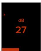
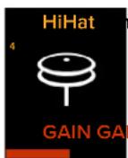
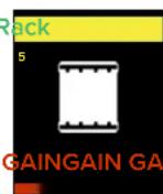


But what about channels that do not have a mic pre? Good question! A channel's digital trim will be displayed on channels that do not have a mic pre.

TRIM Button (ALT + GAIN)
This button selects the digital trim of all channel inputs. Trim is a digital level control at the top of the channel's processing. It affects all input sources to the channel whether analog or digital and is used for adding level to a channel before any of the channel processing.
The trim levels may then be changed by rotating the encoders below the channel displays. A visual representation may be seen on the DC16 channel displays and the input routing screens on Master Fader.
The trim ranges from -40 dB to +20 dB and adjusts in ±1 dB to ±2.5 dB increments. However, these may adjust in 0.1 increments when the shift button is pressed and held while rotating the encoder.
The trim button's LED illuminates white when engaged.


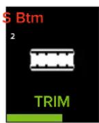
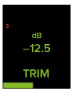


So what is the difference between gain and trim? When would you use gain and when would you use trim? In short, gain is analog, while trim is digital (right after the A/D conversion but before everything else). So if the source is analog, you would use gain. In most cases, you will adjust (analog) gain, not (digital) trim. In some cases, though, you may use both. If the source is digital, you would use trim since it doesn't have gain.

- HPF Button
This button selects the HPF frequency of all inputs and outputs. High-pass filters are utilized to cut out low frequencies. The high-pass filter control adjusts the cut-off frequency for the filter.
HPF levels may then be changed by rotating the encoders and turned on [green] or off [gray] by pushing the encoders below the channel displays. A visual representation may be seen on the DC16 channel displays and the channel's EQ screens on Master Fader.
The HPF ranges from Off to 700 Hz (inputs) and Off to 20 kHz (outputs). The incremental adjustments are dependent on if the selected EQ is modern or vintage.
The HPF button's LED illuminates white when engaged.


- LPF Button (ALT + HPF)
This button selects the LPF frequency of all outputs. [There are no LPF on inputs]. Low-pass filters are utilized to cut out high frequencies. The low-pass filter control adjusts the cut-off frequency for the filter.
LPF levels may then be changed by rotating the encoders and turned on [teal] or off [gray] by pushing the encoders below the channel displays. A visual representation may be seen on the DC16 channel displays and the outputs' EQ screens on Master Fader.
The LPF ranges from Off to 20 kHz. [There is no LPF on the vintage EQ].
The LPF button's LED illuminates white when engaged.
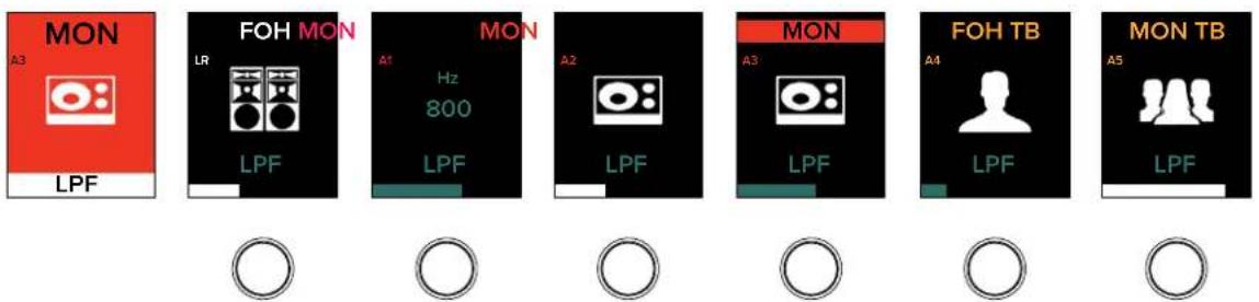

- SEND Button
This button selects the sends of all inputs. This allows you to easily change the levels, as well as mute / un-mute, each channel sent to the auxes and FX.
The send levels are changed by rotating the encoders below the channel displays. A visual representation may be seen on the DC16 channel displays and input routing view on Master Fader.
The send ranges from Off to +10 dB.
The send button's LED illuminates white when engaged.


Simply utilize the editing page buttons to scroll through each of the auxes and FX (and previously mentioned bank or channel buttons to scroll through the other channels).
For linked auxes, the send level will be displayed first. See the image above for an example. Once the (down arrow) channel editing page button is pressed again the send pan will be displayed. See the image below for an example; same screen just paged down.

The channel editing page button LEDs are always illuminated because they are always available. That's right, you can go from aux 1 UP to FX 4 and vice-versa... wrap-around arrows FTW!

While the encoders raise and lower the send levels, that's not all they're good for. No! You can also simply press the encoder to mute and un-mute that channel from the selected aux or FX, as well. As you can see below, the send level on muted channels (3-5) are gray. This function only works when the sends levels are displayed, not the send pans.


This mutes the aux of the selected channel(s), not the master aux. By default, all aux sends are post-mute, which means that pressing the mute button or pressing the encoder is a global mute for the channel. This added feature of pressing the encoder is a convenience for the users that have selected their aux(es) to be pre-mute, making the channel's mute from LR independent of the aux mute. For details of how to change the routing and mute function of the aux/FX sends, please refer to the aux/FX send configuration section of the Master Fader Reference Guide.
The send levels may be changed while muted, but you won't hear the changes until it is un-muted.

L/R Fader / Pan on Per Channel Sends
Here's a neat trick! L/R adjustments may be made on per channel sends via fader and pan. This is explained more easily with an example. Let's go through some steps to show how this works.
Step I – We are already on auxes 3-4, so let's stay there. Make sure you're on the send levels page first. We'll do pans next.
Step 2 - Press and hold the flip buttons until they flash.
Step 3 – We totally just did this step previously, but let's do it again: rotate the encoder to raise and lower the sends level. Did you see the fader move, too?! The encoder and fader are now connected and the sends level may be raised and lowered by either.
Step 4 – Now page down to view the pans and move the encoder again. Boom, the encoder and fader are connected here, as well!
Step 5 - To exit, press and hold the flip buttons until they stop flashing.
DELAY Button (ALT + SEND)
This button selects the delay time of all outputs. [There is no delay on inputs]. This allows you to easily change the delay time level of the LR, all auxes and matrices. This is typically used for speaker alignment.
The delay time levels may then be changed by rotating the encoders below the channel displays. A visual representation may be seen on the DC16 channel displays and input routing view on Master Fader.
The send ranges from 0.0 ms to 334.2 ms and adjusts in ±10 ms increments (except 330 ms to 334.2 ms).
However, these may adjust in 0.1 increments when the shift button is pressed and held while rotating the encoder.
The delay button's LED illuminates white when engaged.


PAN Button
This button selects the pan and balance of all inputs and outputs.
The pan / balance may then be changed by rotating the encoders below the channel displays. A visual representation may be seen at the bottom of the DC16 channel displays and on the pan screen of Master Fader.
As seen in the image below, channel 1 is panned hard left, channel 2 is center panned and channel 3 is panned hard right.
So you can see here that a centered pan is located in the middle of the channel display and anything to the left of that is panned left and anything to the right of that is panned right.

As with Master Fader, what's panned is dependent on the selected mix. In other words, with...:
- LR selected, the encoder will control the LR pan (as seen above).
- An unlinked aux selected, the encoder will not function and the pan screens will be blank (as seen below).
- A linked aux selected, the encoder will control either the LR pan or aux pan depending on the setting of "Use LR Pan" (as seen below).
Unlinked

Linked

The pan ranges from 100L to 100R and adjusts in increments of ±10. However, these may adjust in ±1 increments when the shift button is pressed and held while rotating the encoder.
The pan button's LED illuminates white when engaged.

USER Button (ALT + PAN)
The USER button allows you to set a custom control for each channel when used in conjunction with the modifier buttons. Put another way, it's a customizable all-channel edit mode. For example, the channel 1 user control could be a mic pre while channel 2 could be EQ band 2 frequency and so on and so forth. This might make better sense if we go through a series of steps.
Step 1 – Press and hold the ALT button while also pressing the PAN button. This will get you into USER mode. The PAN/USER button LED will illuminate white, confirming just how on it is. Additionally, look how the channel displays change simply by entering USER mode. The gain levels are gone!
NORMAL MODE


USER MODE




Step 2 – Select a channel by pressing and holding the ASGN button down while simultaneously pressing a channel's encoder. This selects which encoder will have the parameter you choose associated with it. Release the buttons. The ASGN button's LED should be flashing red and the channel's SEL(ect) button's LED should be flashing white.
Assign Mode: USER Enc Ch1
USER Control: GAIN
Step 3 – For this example, we'll update the all-channel gains, so tap the gain button followed by pressing the channel's encoders that you want gain available. Since we just want to see the drums gains, we're pressing the channel I-6 encoders. Take note of the selected channel display which shows the current control of the encoder (to the left).
Step 4 - Press the ASGN button again to exit assign mode.
Step 5 - When you re-enter USER mode (ALT + PAN), you should notice that the channels that were selected (I-6) will display the gains, but channels not assigned will have the gains missing from the channel display.
Step 6 - You're done! Un-assigning channels is just as easy. While in USER mode, press and hold the ASGN button while simultaneously pressing and holding the channel's encoder down for three seconds to de-select.
What this is good for is quick access and workflow expediency. So, regardless of what channels you're viewing, what bank you're on, etc., you can view your changes immediately by re-entering USER mode. Try it! Press another channel editing button (EQ, send, etc.) followed by re-entering USER mode. Notice how the channel displays show the channels assigned to (in this case) the gain.
The possibilities are not endless, but it is seemingly so. Sixteen channel encoders that may each have a different parameter associated with it, multiple inputs and outputs to select from and more.
That wraps up the ALL portion of channel editing meaning we're on to the SELECTED portion of channel editing. As a reminder, SELECTED channel editing allows adjustment of the selected group of parameters for the SELECTED channel. Let's take a look...
EQ Button
This button selects and displays the EQ parameters of the selected channel for editing. There is a plethora of EQ-related information detailed in the Master Fader Reference Guide. All of the major EQ-related parameters may be accessed and changed via DC16. This includes gain, frequency and Q (including shelf / bell selection) and a high-pass filter (HPF). Furthermore, you're able to select between mixing with (clean, surgical, precise) modern EQ or (classic sounding and looking) vintage EQ.

Please keep in mind that you can really upset things with too much EQ. Each EQ band has a lot of boost and cut because that is needed on occasion. But if the EQ is maxed on every channel, the mix turns to mush. Equalize subtly, using cut, as well as boost. If you find yourself repeatedly using a lot of boost or cut, consider altering the sound source, such as placing a mic differently, trying a different kind of mic, a different vocalist, changing the strings, gargling, or all of the above.
The EQ parameters may then be changed by rotating and/or pushing the encoders below the channel displays. A visual representation may be seen on the DC16 channel displays and the EQ screen on Master Fader.

Do you notice the different colors in the images below? These colors align with the colors as seen in the EQ section of Master Fader for continuity. As it is with Master Fader, this is for easy identification between the different EQ bands.
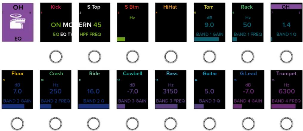
There will always be one channel editing page button LED illuminated in order to cover all EQ parameters. An example of the Page I EQ parameters is displayed above and page 2 may be seen below.




If you want to update the EQ parameters of an output – LR, auxes, subgroups and/or matrices – that may also be done here. Instead of selecting a channel, though, select an output. The visuals are similar to that of the input channel's EQ shown above, but for the output.
The EQ button's LED illuminates white when engaged.

ASSIGN Button (ALT + EQ)
The ASSIGN button displays channel assignments to a variety of audio and control groups. Put another way, this is the place to route (or assign) the I/O via DC16. Let's see how it works.
Press and hold the ALT button down while simultaneously pressing the EQ button to enter ASSIGN mode. The EQ / ASSIGN button's LED will illuminate white, indicating that it is on. Additionally, the channel displays will change as seen below. A regular view of looking at the mix deck of the channel gains is on top, while the mix deck below that is similar to what it will look like upon entering ASSIGN mode.
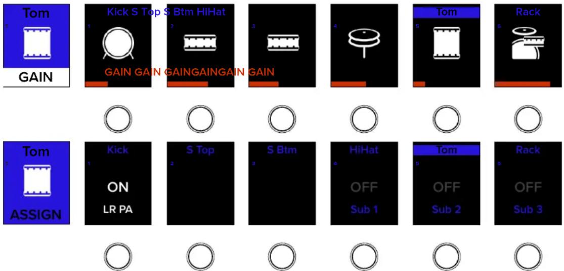
Now what we're going to want to do is route the drums to subgroup 1... but on DC16, not Master Fader. This task is very easy.
Step 1 - You're already in ASSIGN mode. The next step is to SEL(ect) a channel. The drums are on channels 1-6, so let's go left to right. SEL(ect) channel 1 (Kick) so its button's LED illuminates white.
Step 2 – All input channels are automatically routed to the main LR. This is noted above on the channel display (LR PA = ON). That said, it may be removed from being routed to the main LR by pushing the encoder underneath it. Press it a few times to see the routing turn on and off. Also of note are subs I-3. Those are in grey text and listed as OFF. In order to assign the channel 1 Kick to Sub 1, push the encoder underneath Sub 1.
Step 3 – Follow steps 1 and 2 for the remaining (drum) channels. You can also watch along in Master Fader to see the changes happening on the fly!
Inputs aren't only assignable to subs. No way! We've got you covered with VCAs, Mute Groups and View Groups, too... just as it is on Master Fader! Use the up and down flip arrows to switch between subs / VCAs and the mute / view groups. Also, bank or channel left or right to view other channels that you may want to route.
Outputs may also be routed to a variety of group assignments. As with the inputs, simply select the output that you want to assign, then assign to the following:
• LR, auxes and matrices may be assigned to Talkback, VCAs and Mute Groups
• FX may be assigned to Mute Groups
- Subgroups may be assigned to the Main LR, VCAs, Mute Groups and View Groups
• VCAs may be assigned to View Groups
There is a wealth of information about input and output routing in the Master Fader Reference Guide.
GEQ Button
This button selects and displays the GEQ parameters of the selected output for editing. [There is no GEQ on inputs]. GEQ is a great tool for really dialing in the response needed for a room or to squelch feedback from monitors.
The GEQ parameters may then be changed by rotating the encoders below the channel displays. A visual representation may be seen on the DCIG channel displays and the GEQ screen on Master Fader.
The GEQ gain ranges from -12 dB to +12 dB and adjusts in ±1 dB increments. However, these may adjust in 0.1 increments when the shift button is pressed and held while rotating the encoder. The frequency bands are listed near the bottom of each channel display, just above gain range bar.

other
| Instrument | Frequency (dB) | Strength (GHz) | | :--- | :--- | :--- | | FOH TB A5 | 0 | 0 | | Kick ON GEQ 25 | 1 | 0 | | S Top dB | 2 | 0 | | S Btm dB | 3 | 0 | | HiHat dB | 4 | 0 | | Tom dB | 5 | 0 | | Rack dB | 6 | 0 | | OH dB | 7 | 0 | | Floor dB | 9 | 0 | | Crash dB | 10 | 0 | | Ride dB | 11 | 0 | | Cowbell dB | 12 | 0 | | Bass dB | 13 | 0 | | Guitar dB | 14 | 0 | | G Lead dB | 15 | 0 | | Trumpet dB | 16 | 0 | | Sax dB | 17 | 0 |There will always be one channel editing page button LED illuminated in order to cover all 3I GEQ bands. An example of the page I GEQ parameters is displayed above and page 2 may be seen below.
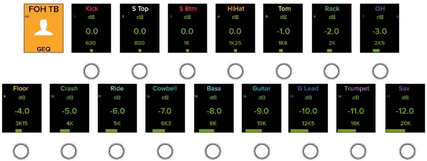
bar
| Category | Value | |---|---| | Floor (dB) | -4.0 | | Crash (dB) | -5.0 | | Ride (dB) | -6.0 | | Cowbell (dB) | -7.0 | | Bass (dB) | -8.0 | | Guitar (dB) | -9.0 | | G Lead (dB) | -10.0 | | Trumpet (dB) | -11.0 | | Sax (dB) | -12.0 |The GEQ button's LED illuminates white when engaged.
SENDS Button (ALT + GEQ)
This button displays each channels' send levels, allowing you to easily change the aux and FX levels of the selected input.
The sends levels may then be changed by rotating the encoders below the channel displays. A visual representation may be seen on the DC16 channel displays and input routing view on Master Fader.
The sends ranges from Off to +10 dB and may be adjusted in 0.1 increments when the shift button is pressed and held while rotating the encoder.

other
| Category | Label | Value | | -------- | ----- | ----- | | OH | SENDS | 7 | | Kick | dB | -40.0 | | S Top S Btm | OFF | 2 | | HiHat | dB | -16.0 | | 50L | LR PAN | 4 | | Tom Rack | dB | -18.0 | | 20R | LR PAN | 6 | | Floor | dB | -8.0 | | Crash | dB | 1.0 | | Ride | dB | -18.0 | | Cowbell | dB | -20.0 | | Bass | dB | 10.0 | | Guitar | dB | - | | G Lead | dB | 15 | | Floor | dB | -8.0 | | Crash | dB | 1.0 | | Ride | dB | -18.0 | | Cowbell | A11 Front Fill | 12 | | Bass | A12 Side Fill | 13 | | Guitar | dB | - | | G Lead | dB | - | | Floor | dB | -8.0 | | Crash | A9 Ears | 10 | | Ride | A10 Ears | 11 | | Cowbell | A11 Front Fill | 12 | | Bass | A12 Side Fill | 13 | | Guitar | dB | - | | G Lead | dB | - | | Floor | A8 IEM | 9 | | Crash | A9 Ears | 1.0 | | Ride | A10 Ears | - | | Cowbell | A11 Front Fill | - | | Bass | A12 Side Fill | - | | Guitar | dB | - | | G Lead | dB | - | | Floor | dB | -8.0 | | Crash | A9 Ears | - | | Ride | A10 Ears | - | | Cowbell | A11 Front Fill | - | | Bass | A12 Side Fill | - | | Guitar | dB | - | | G Lead | dB | - | | Floor | dB | -8.0 | | Crash | A9 Ears | - | | Ride | A10 Ears | - |Simply utilize the editing page buttons to scroll through the auxes and FX (and previously mentioned bank or channel buttons to scroll through the other channels). There will always be one channel editing page button LED illuminated, as page 1 covers all of the auxes (see above) and page 2 covers the FX. Once the (down arrow) channel editing page button is pressed, the channel's FX levels will be displayed. See the image below for an example; same screen just paged down.
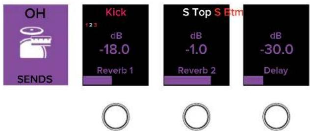
bar
| Metric | Value | |--------|-------| | OH | 12.3 | | Kick | -18.0 | | S Top S Btm | -1.0 | | Delay | -30.0 |The SENDS button's LED illuminates white when engaged.

DYN(amics) Button
This button displays the gate and compressor controls of the selected input for editing. Gates are typically used to reduce leakage from open microphones. Signals below the threshold level are muted, while signals above the threshold get to pass through. Compressors are used to reduce or limit transient peaks in a signal. If the signal is too hot, the compressor turns it down; otherwise it leaves it alone. More information on the workings of the dynamics processors may be found in the Master Fader Reference Guide.
The following dynamics-related parameters may be accessed and changed via DC16: threshold, range, attack, hold and release [GATE] and comp knee, threshold, ratio, attack, release and gain [COMP]. Furthermore, you're able to select between mixing with (clean, surgical, precise) modern dynamics or (classic sounding and looking) vintage dynamics.
The gate and comp parameters may then be changed by rotating [levels] and/or pushing the encoders [on / off] below the channel displays. A visual representation may be seen on the DC16 channel displays and the dynamics screen on Master Fader.
Do you notice the different colors in the images below? These colors align with the colors as seen in the dynamics section of Master Fader for continuity. As it is with Master Fader, this is to easily identify between the gate and compressor parameters.




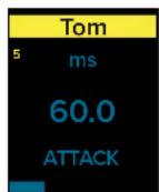




Now if you select one of the outputs - LR, auxes or matrices - you will be presented with a couple more options. The output delay may be turned on / off and their associated parameters updated. Additionally, the temperature may be updated here, as well. Simply select one of the aforementioned outputs to see something similar to what's displayed below.


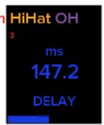
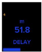

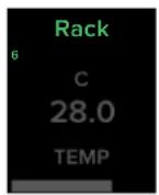


The output delay and temperature parameters may then be changed by rotating [levels] and/or pushing the encoders [on / off] below the channel displays. The three listed delay times are adjoined and work together. In other words, changing the delay of the ms will also change the delay of the m and ft automatically. This is also true of the temperature controls. If the output delay is off, the delay times will be visible (although grayed out), but they cannot be updated until the delay is turned back on.
The DYN button's LED illuminates white when engaged.
Enough about gates and compressors... let's move onto what setup is all about, if but for a moment!

SETUP Button (ALT + DYN)
This button selects and displays the initial setup controls and a few other goodies.
SETUP is unique. So unique, in fact, that it has a dedicated section all to itself! Please refer to pages 86-94 for more information about setup.

FX Button
This button selects and displays the FX controls for the reverb, delay and modulation processors for editing. These FX may be fed from any combination of channels with dedicated FX sends. We follow standard FX send and return configuration, allowing you to easily adjust the FX in one convenient location for each selected channel. There is a plethora of FX-related information detailed in the Master Fader Reference Guide.
The FX parameters may then be changed by rotating the encoders below the channel displays. A visual representation may be seen on the DC16 channel displays and the FX screen on Master Fader.
Press the FX button to create and adjust the FX parameters to your liking. Press the FX button to be presented with something similar to the following on the channel displays:
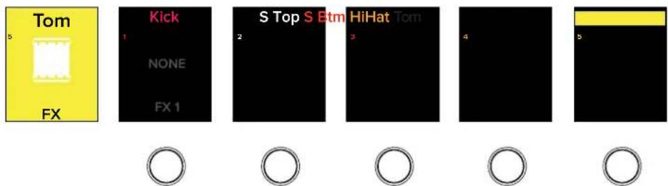
Press the encoder located on the far left to select an FX. The channel displays will look similar to what's displayed below:

flowchart
graph TD
    A["None Plaza"] --> B["Selected"]
    C["Reverb Reverb"] --> D["AMBIANCE"]
    E["SMALL ROOM"] --> F["MED ROOM"]
    G["REVERB REVER"] --> H["LRG ROOM"]
    I["REVERB"] --> J["HALL"]
    K["VERB"] --> L["CATHEDRAL"]
    M["VERB"] --> N["GATED"]
    O["SPRING"] --> P["Exit?"]
Once an FX is decided upon, push the encoder to select it.

Not all FX are displayed above. There are still more, including additional reverbs, delays and modulation. Use the up and down flip arrows to switch between pages and view even more FX!
For FX I, we'll go with a spring reverb. Notice how the channel displays now presents the spring reverb parameters. Once here, you may use the encoders underneath each parameter to change to your liking.
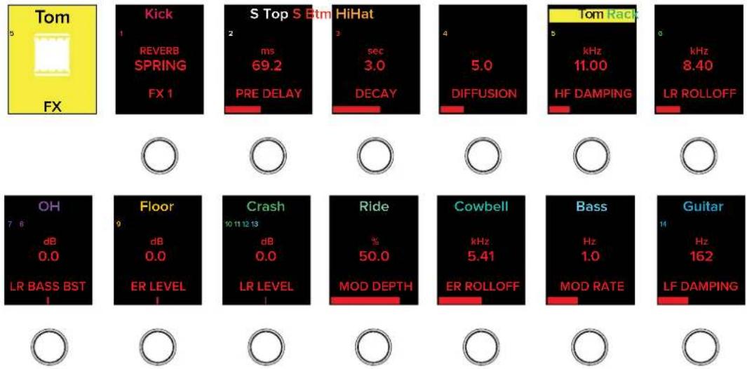
From here, you may follow these same instructions to load up FX 2-4.
Simply utilize the flip arrow buttons to scroll through the FX (and previously mentioned bank or channel buttons to scroll through the other channels). Once the channel editing page button is pressed, the channel's FX parameters will be displayed. See the image below for an example; same screen as above, but just paged down.


As mentioned earlier, changes to each parameter is handled by rotating the encoder underneath each parameter. However, fine adjustments to the parameters may be made by holding down the DC16's Shift key while also simultaneously rotating the encoder.
The FX button's LED illuminates white when engaged.
TRANS(port) Button (ALT + FX)
The TRANS(port) button allows you to control the transport parameters when a USB drive is connected to the DL32R. After connecting a hard drive to the DL32R, press the ALT + FX buttons on the DC16 to enter TRANS(port) mode.
The first page of the channel screens displays the music playback screen and will look something similar to what may be seen below:
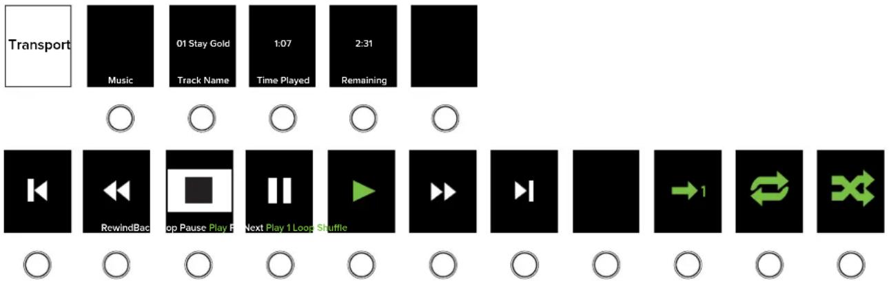
Now press the page down flip button to view page two. It will display the multichannel record/playback screen and will look something similar to what may be seen above except that:
(I) These are the multichannel record/playback controls
(2) A section for record is placed between Play and FF
(3) Shuffle has been removed and is not an option to select.
We won't get into details about how these functions work because they are described to a nearly ad nauseam level in the Master Fader Reference Guide. Please refer to it on how recording and playback works, as well as how all of these transport controls work.

If you try entering TRANS mode without a hard drive connected to the DL32R, you will end up with an error message similar to the following:





Fat Channel
The Fat Channel is conveniently located dead center of the DC16 above the channel IDs and in front of the center tablet. In addition to the fader controls, the Fat Channel is likely where you will spend the majority of time. Why? Well, because it contains access to the most frequently updated controls for the selected input or output channel, regardless of what channel editing button is currently engaged (see pages 47-62, 86-94).
- Gain / Trim Encoder
• 48v Phantom Power Button - Polarity [0] Invert Button
- HPF / LPF Encoder
• Four-band Parametric EQ Buttons and Encoders [Gain, Freq, Q]
• Gate Thresh / Range Encoder
• Comp Thresh / Ratio Encoder - Pan / Delay Encoder

Fat Channel
Let's take a brief look at each of these features starting in the upper-left corner with the gain and trim encoder...

GAIN Encoder
This encoder adjusts the level of the mic pre gain of the selected input. Gain adjusts the input sensitivity of the mic and mic/line inputs. This allows signals from the outside world to be adjusted to run through each channel at optimal internal operating levels.
Setting the preamp gain correctly with the gain control is an essential step in establishing good signal-to-noise ratio and sufficient headroom for the mix because its setting determines the overall noise performance in that channel.
But what about channels that do not have a mic pre? Good question! A channel's digital trim will be adjusted on channels that do not have a mic pre.
The gain ranges from 0 dB to 60 dB and adjusts in ±3 dB increments.
A visual representation of the changes may be seen on the channel's input routing screens on Master Fader.

TRIM Encoder (ALT + GAIN)
This encoder adjusts the level of the digital trim of the selected input. Trim is a digital level control at the top of the channel's processing. It affects all input sources to the channel whether analog or digital and is used for adding or removing level to a channel before any of the channel processing.
The trim ranges from -40 dB to +20 dB and adjusts in ±1 dB to ±2.5 dB increments. However, these may adjust in 0.1 increments when the shift button is pressed and held while rotating the encoder.
A visual representation of the changes may be seen on the channel's input routing screens on Master Fader.

So what is the difference between gain and trim? When would you use gain and when would you use trim? In short, gain is analog, while trim is digital (right after the A/D conversion but before everything else). So if the source is analog, you would use gain. In most cases, you will adjust (analog) gain, not (digital) trim. In some cases, though, you may use both. If the source is digital, you would use trim since it doesn't have gain.

48v Phantom Power Button
This button turns phantom power on and off of the selected input. The 48v button LED illuminates red on channels that have phantom power engaged.
It has no effect if the selected channel does not have a mic pre.
A visual representation of the change may be seen on the channel's input routing screen on Master Fader.

Polarity Invert [∅] Button
This button turns polarity on and off of the selected input. The polarity button [∅] LED illuminates orange on channels that have polarity engaged.
It has no effect if the selected channel does not have a polarity invert.
A visual representation of the change may be seen on the channel's input routing screen on Master Fader.
![MACKIE DC-16 - Polarity Invert [∅] Button - 1](/content/2026/05/811442/images/de8f41cadbb47c1e47ffed47bcf6301f5679fed4ff0524dab22066452c67863d.jpg)
HPF Encoder
This encoder adjusts the High Pass Filter frequency of the selected input or output. The HPF frequency is changed by rotating the encoder and turned on [green] or off [white] by pushing the encoder. High-pass filters are utilized to cut out low frequencies. The high-pass filter control adjusts the cut-off frequency for the filter.
The HPF ranges from Off to 700 Hz (inputs) and Off to 20 kHz (outputs). The incremental adjustments are dependent on if the selected EQ is modern or vintage.
A visual representation may be seen on the EQ screens on Master Fader.

LPF Encoder (ALT + HPF)
This encoder adjusts the Low Pass Filter frequency of the selected output. [There are no LPF on inputs].
The LPF frequency is changed by rotating the encoder and turned on [green] or off [white] by pushing the encoder. Low-pass filters are utilized to cut out high frequencies. The low-pass filter control adjusts the cut-off frequency for the filter.
The LPF ranges from Off to 20 kHz. [There is no LPF on the vintage EQ].
A visual representation may be seen on the EQ screens on Master Fader.
• Four-band Parametric EQ Buttons and Encoders [GAIN, FREQ, Q]

The four "BAND" buttons allow you to select which EQ band you want to update of the selected input or output. The currently selected band button LED illuminates white when engaged. One of these EQ button LEDs will always be illuminated, but never more than one.
Once a band is selected, rotate the encoders located above these buttons to change the gain, frequency and Q (if applicable) of that band. The EQ may be turned on [green] or off [white] by pushing the gain encoder.
A visual representation of the changes may be seen on the EQ screen on Master Fader.
![MACKIE DC-16 - • Four-band Parametric EQ Buttons and Encoders [GAIN, FREQ, Q] - 2](/content/2026/05/811442/images/9ab1a8f0b92e8c61d27a589e67826daec33fd03417f5269bd0c0279ee48491ac.jpg)
GATE THRESH Encoder
This encoder adjusts the gate threshold of the selected input. [There are no gates on outputs]. The threshold is changed by rotating the encoder and the gate may be turned on [green] or off [white] by pushing the encoder. Threshold determines the level below which the gate acts on the incoming signal.
The range of the threshold setting varies from 80 dBFS to 0 dBFS. The incremental adjustments are dependent on if the selected gate is modern or vintage.
A visual representation of the changes may be seen on the dynamics screen on Master Fader.

GATE RANGE Encoder (ALT + GATE THRESH)
This encoder adjusts the gate range of the selected input. [There are no gates on outputs]. The range is changed by rotating the encoder and the gate may be turned on [green] or off [white] by pushing the encoder. Range determines how far the gain is reduced once the signal is below threshold.
The range of the gated signal varies from 0 dB to 60 dB. [There is no range when vintage gate is selected].
A visual representation of the changes may be seen on the dynamics screen on Master Fader.
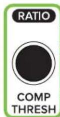
COMP THRESH Encoder
This encoder adjusts the comp threshold of the selected input or output. The threshold is changed by rotating the encoder and the comp may be turned on [green] or off [white] by pushing the encoder. Threshold sets the threshold of the compressor in dB below 0 dBFS.
The range of the threshold setting varies from -80 dBFS to 0 dBFS. The incremental adjustments are dependent on if the selected comp is modern or vintage.
A visual representation of the changes may be seen on the dynamics screen on Master Fader.

COMP RATIO Encoder (ALT + COMP THRESH)
This encoder adjusts the comp ratio of the selected input or output. The ratio is changed by rotating the encoder and the comp may be turned on [green] or off [white] by pushing the encoder. Ratio sets the amount of gain reduction applied as the signal exceeds the threshold level.
The range of the ratio of the compressor varies from I:I to inf:I. The incremental adjustments are dependent on if the selected comp is modern or vintage.
A visual representation of the changes may be seen on the dynamics screen on Master Fader.

PAN Encoder
This encoder adjusts the pan or balance of the selected input group and Main L/R. The pan / balance is changed by rotating the encoder.
As with Master Fader, what's panned is dependent on what's selected. In other words, with...:
- A mono (unlinked) input or subgroup selected, the encoder will control that input's LR pan.
- A stereo (linked) input or subgroup selected, the encoder will control that input's LR balance.
- Main LR selected, the encoder will control the Main LR balance.
A visual representation may be seen on the pan / balance screen on Master Fader.

DELAY Encoder (ALT + PAN)
This encoder adjusts the alignment delay of the selected output, allowing you to easily change the delay time level of the LR, all auxes and matrices.
A visual representation of the changes may be seen on the output's compressor / limiter / delay screen on Master Fader.
Snapshot Control
The snapshot control section - "SHOW" - is located in the upper-right corner of DC16 just below the three analog controls and above the mix selector - "MIXES". Here you are able to easily view, select, recall and store snapshots. Let's find out how!
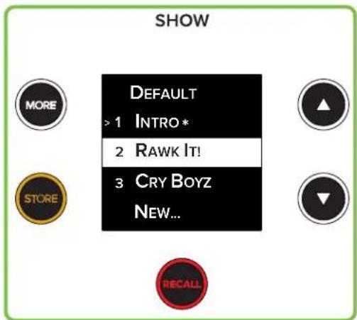
Snapshot Control
• Display
As seen above, the SHOWs display section features a list of the current show's snapshot list that includes the snapshot number, name and indicator.

Snapshot indicators:
= Currently loaded snapshot.
^* = If the current state is different than the snapshot.
Highlighted = Snapshot ready for recall or replacing via Store.
Please note that there will only be one of each snapshot indicator. If no snapshots have been stored, then "Default" will be the currently selected snapshot [>] and the "New..." snapshot will be highlighted.
While snapshots may be displayed, recalled and stored (and more!) via DC16, the names of the snapshots will still need to be created using Master Fader's onscreen keyboard.
ARROW Buttons
Press the up and down arrows to highlight a snapshot. From there you're able to recall, store or create a new snapshot.
These arrow button LEDs are always illuminated because they are always available (unless the MORE button has been engaged... MORE on that on the next page). That's right, you can go from the Default snapshot UP to the last snapshot of the show and vice-versa. Even if it's a brand-new show with only the Default and New... snapshots available... wrap-around arrows FTW!
RECALL Button
This button recalls snapshots via DC16. Pressing the RECALL button once causes the button's LED to flash red. In order to recall this snapshot, you will need to press the button a second time (within five seconds of the first press) to confirm the recall. After five seconds of inactivity, the store button's LED reverts back to its solid red state.
After a snapshot has been recalled, the currently loaded snapshot indicator [>] changes. Furthermore, that same snapshot highlights, indicating that it has been recalled. It will remain highlighted until an arrow button is pressed, highlighting another snapshot.

The recall button's LED will remain solid red when it is available for use. This is always the case unless: (1) the button has been pushed (in which case it will flash red for the aforementioned five second period) or (2) "New..." is the highlighted snapshot. After all, a new snapshot cannot be recalled, only stored!

As with Master Fader, recalling snapshot "O - Default" on DC16 will set the Master Fader to its default (which – for all intents and purposes – is a zeroed out board). Snapshot "O - Default" is always listed first and cannot be renamed, replaced or deleted; only recalled.

STORE Button
This button stores snapshots via DC16. Tapping the STORE button will store the current state of the console [the faders, EQs, gates and compressors, etc.] that you just set to a new snapshot or as a replacement.
Here, pressing the store button once causes the button's LED to flash orange. In order to store this snapshot, you will need to press the button a second time (within five seconds of the first press) to confirm the store. After five seconds of inactivity, the store button's LED reverts back to its solid orange state.

Creating a NEW SNAPSHOT is as simple as highlighting the "New..." snapshot at the bottom of the list and following the directions outlined above.
REPLACING A SNAPSHOT is as simple as highlighting any current snapshot on the list and following the directions outlined above. Please be aware that doing so erases all of your previously stored settings.
The store button's LED will remain solid orange when it is available for use. This is always the case unless: (1) the button has been pushed (in which case it will flash orange for the aforementioned five second period) or (2) "Default" is the highlighted snapshot. After all, the default snapshot cannot be stored, only recalled!

MORE Button
This button replaces the current channel display with show and snapshot information. Tap the MORE button for a visual representation. The selected channel display will state Show Channel Safes while the remaining channel displays present whether that channel is locked ("safe") or not ("off"). Use the flip arrow buttons to review the remaining channels, returns, FX, auxes, etc. safe status. The last page displays the channel safe status of LOCK Channels, LOCK Mixes, USER Encoders, USER Buttons, All Routing and DC16 Routing. All parameters listed may be locked/unlocked by pressing the adjacent encoder.
Additionally, the shows display presents the show name, number of snapshots and images. Pressing the down arrow will present the created and modified date stamps. The MORE button's LED illuminates white when pressed. Press the MORE button again to return to the previous view.
Analog Controls
These three analog controls (located in the upper-right corner of DC16) allow you to raise and lower the talkback, monitor and headphones levels. Because these are analog controls, they are NOT recallable.

TALKBACK

MONITOR

PHONES
Analog Controls
• TALKBACK Knob
This knob controls the input level of the talkback mic with the gain ranging from a low of off ( - ) up to a maximum of +10 dB. The talkback output level is set up via Master Fader's Quick Access Panel.

Talkback may be routed to the main L/R, any subgroup, aux send and/or matrix and is set up via Master Fader's I/O patch.
• MONITOR Knob
This knob controls the level for the monitor bus with the level ranging from a low of off (-) up to a maximum of +10 dB.
- PHONES Knob
This knob is used to adjust the volume from the phones output jack, from a low of off (-) up to maximum gain (max).

Warning: The headphone amp is loud and could cause permanent hearing damage. Even intermediate levels may be painfully loud with some headphones. BE CAREFUL! Always turn the phones knob all the way down before connecting headphones, soloing a channel or doing anything new that may affect the headphone volume. Then turn it up slowly as you listen carefully.
Modifiers
The modifiers section is located on the left-hand side of DC16 just below the groups section. It consists of four buttons that are used to modify the functionality of other controls. These buttons are simply modifiers and won't work on their own. Instead, they are to be used in conjunction with other buttons or encoders in order to update settings. We'll go over each of the buttons starting at the left and head our way right.
- Alt Button
- Shift Button
- Assign Button
- Lock Button
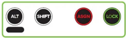
Modifiers

ALT Button
On its own, the ALT button does absolutely nothing – just like me on evenings, weekends (and most of the time at work, too!) – but when pressed and held, a multitude of possibilities are at your disposal.
Just below the ALT button is a blank horizontally-lined capsule-shaped design [____]. This is for easy representation of what parameter is available for change. There are other “horizontally-lined capsule-shaped designs” placed above and below some of the buttons and encoders throughout DC16, but these are not blank. Instead, the text represents what function may be updated when pressing and holding the ALT button while pressing the button or turning the encoder. Each of these functions is explained in greater detail with the function and page numbers listed below:
ALT Button + Channel Editing Button:
• ALT + Gain = Trim - page 48
• ALT + HPF = LPF - page 49
• ALT + Send = Delay - page 51
• ALT + Pan = User - page 53
• ALT + EQ = Assign - page 55
• ALT + GEQ = Sends - page 57
- ALT + DYN = Setup - page 86-94
- ALT + FX = Trans - page 62
ALT Button + Fat Channel Encoder:
• ALT + Gain = Trim - page 63
• ALT + HPF = LPF - page 64
- ALT + Gate Thresh = Gate Range - page 65
- ALT + Comp Thresh = Comp Ratio - page 65
- ALT + Pan = Delay - page 65

SHIFT Button
The SHIFT button is used in conjunction with the encoders to make fine-tuned adjustments to the input and output parameters. Just push and hold the button down while rotating the encoder of the selected parameter.

While nearly every parameter may be fine-tuned, not every parameter has that option.
The SHIFT button's LED illuminates white when pressed and held.

ASGN Button
This button is used in conjunction with other buttons to adjust input and output assignments. There's a lot of info here, so please pay attention!
The button's LED illuminates solid red when pressed and held, but another button must be pressed in order to enter what's called "Assignment Mode".
When in assignment mode:
(I) the ASGN button's LED will flash red.
(2) the selected channel display will present the selected function (similar to what may be seen in the images to the left of each description).

Even while in assignment mode, you are still able to mix the show as usual and navigate through the other banks of channels, too, as every control (other than SEL) doesn't change its function. You'll use this to find the channels you wish to assign and unassign. Just be careful to leave assignment mode when finished to prevent inadvertently assigning / unassigning channels while still in assignment mode.
Pressing the flashing ASGN button again ends assignment mode.
Assign Mode: Main LR FOH
- ASGN + Main LR – Pressing and holding the ASGN button while pressing the [Mix Selector] Main L/R button puts the console into assignment mode for the Main L/R. The SEL button LEDs of channels that are already assigned to the Main L/R will flash, indicating that they are assigned to the Main L/R. From here you're able to assign and unassign channels to the Main L/R simply by pressing the channels' SEL button.
Assign Mode: Subgroup 1 MON
- ASGN + Subgroup – Pressing and holding the ASGN button while pressing one of the [Mix Selector] subgroup buttons – whether the subgroup is linked or unlinked – puts the console into assignment mode for that subgroup. The SEL button LEDs of channels that are already assigned to the chosen subgroup will flash, indicating that they are assigned to that subgroup. From here you're able to assign and unassign channels to the selected subgroup simply by pressing the channels' SEL button.
Assign Mode: VCA 2 HORNS
- ASGN + VCA – Pressing and holding the ASGN button while pressing one of the [Mix Selector] VCA buttons puts the console into assignment mode for that VCA. The SEL button LEDs of channels that are already assigned to the chosen VCA will flash, indicating that they are assigned to that VCA. From here you're able to assign and unassign channels to the selected VCA simply by pressing the channels' SEL button.
Assign Mode:
View Group E view group Song IV
- ASGN + View Group – Pressing and holding the ASGN button while pressing one of the [Groups Selector] view groups buttons [view group A-F] puts the console into assignment mode for that view group. The SEL button LEDs of channels that are already assigned to the chosen view group will flash, indicating that they are assigned to that view group. From here you're able to assign and unassign channels to the selected imply by pressing the channels' SEL button.
More information about view groups may be found on pages 27-28.
Assign Mode:
Mute Group 3 Song II
- ASGN + Mute Group – Pressing and holding the ASGN button while pressing one of the [Groups Selector] mute groups buttons [mute group I-6] puts the console into assignment mode for that mute group. The SEL button LEDs of channels that are already assigned to the chosen mute group will flash, indicating that they are assigned to that mute group. From here you're able to assign and unassign channels to the selected mute group simply by pressing the channels' SEL button.
More information about mute groups may be found on pages 29-30.
Assign Mode: Talkback
- ASGN + Talkback – Pressing and holding the ASGN button while pressing the talkback button puts the console into assignment mode. The SEL button LEDs of outputs that have talkback already assigned to them will flash, indicating that they are assigned to talkback. From here you're able to assign and unassign outputs to talkback simply by pressing the outputs' SEL button (after chosen in the mix selector).
More information about talkback may be found on pages 46, 68 and 87.

LOCK Button
The LOCK button has a multitude of functions. It allows you to change the layout of channels and controls, perform certain lock operations and more. Like the ASGN button that was just described, the LOCK button is also used in combination with other buttons. Let's take a look...
Assign Mode: Channel Lock
Channel locking – channel locking affords you the ability to lock input and output channels to the mix deck. We'll start with locking channel inputs.
Step 1 – Press and hold the ASGN + LOCK buttons until the selected channel display reveals something similar to what may be seen to the left, then release. The ASGN button will be flashing red.
Step 2 – Press the SEL buttons of the channels you want locked to the mix deck. Bank over to view and select the other channel inputs. The chosen SEL button LEDs will flash. If you made an oopsie-daisy by selecting a channel you did not want selected, simply press that channel's SEL button again to deselect.
Step 3 - Press the ASGN button again to leave assign mode.
Step 4 – Now engage and disengage the LOCK button while viewing the channel displays. Notice that the locked channels will have a small padlock icon located near the top-center of each channel display, indicating that they are locked. It's even in the same color as the channel itself! Additionally, the LOCK button LED illuminates solid green.
Step 5 – We are essentially finished, but let's take a look at one more thing. Engage the LOCK button again. Now bank to the right. Notice that the channels you locked remain on the far-left of the mix deck, while the remaining channels are visible on the remaining channel strips. When the LOCK button is disengaged, the entire mix deck is unlocked and available, so banking will work as it normally does.

Multiple channels of any type may be locked in place. That said, while you are certainly able to SEL (ect) as many inputs as you desire, only a maximum of eight may be locked simultaneously.

Locked channels still follow the selected parameter editing and the output selector.

One final note regarding channel locking. Locked inputs may be justified to the left or right side of the mix deck. This may be updated in setup mode. More information may be found on page 90.
If the "Show Locked Channels in View Groups" setting is turned on in setup mode, then the view groups will display the locked channels. Try it! Press the View button (if not already engaged), followed by selecting one of the view groups. All channels disappear from the mix deck except for the locked channels (and any channels that are assigned to a view group). More information may be found on page 91.
Locking output channels to the mix deck is just as easy as locking the input channels.
Step I - Press and hold the ASGN + LOCK buttons until the selected channel display reveals that it is in Channel Lock mode, then release. The ASGN button will be flashing red.
Step 2 - Press the MAST button on the mix selector so the outputs are arranged on the mix deck.
Step 3 – Press the SEL buttons of the outputs you want locked to the mix deck. Bank over to view and select the other outputs. The chosen SEL button LEDs will flash. If you made an oopsie-daisy by selecting an output you did not want selected, simply press that output's SEL button again to deselect. All outputs are available for selection: main L/R, auxes, FX, subgroups, VCAs and matrices.
Step 4 – Press the ASGN button again to leave assign mode.
Step 5 – Now engage and disengage the LOCK button while viewing the channel displays. Notice that the locked outputs will have a small padlock icon located near the top-center of each channel display, indicating that they are locked. It's even in the same color as the output itself! Additionally, the LOCK button LED illuminates solid green.
Step 6 – We are essentially finished, but let's take a look at one more thing. Leave the masters section by pushing the MAST button again. The mix deck should return to display all of the input channels. However, engage the LOCK button again. Notice that the outputs you locked remain on the far-right of the mix deck, while the remaining outputs are visible on the remaining channel strips. When the LOCK button is disengaged, the entire mix deck is unlocked and available, so banking will work as it normally does.

Multiple outputs of any type may be locked in place. That said, while you are certainly able to SEL(ect) as many outputs as you desire, only a maximum of eight may be locked simultaneously.

The outputs will be arranged in the same standard order on the mix deck: LR, auxes, FX, subgroups, VCAs and matrices. In other words, it cannot be rearranged to matrix I followed by subgroups 4 and 3 and auxes, for example.

Locked channels still follow the selected parameter editing and the output selector.

One final note regarding channel locking. Locked outputs may be justified to the left or right side of the mix deck. This may be updated in setup mode. More information may be found on page 91.
Auto Spill Locked Mixes - Locked mixes may be "auto spilled" to the mix deck via single or double-tap of a SEL(ect) button. This is best easily explained with an example. Let's assume the following:
- Input channels I-8 are the drums and they are assigned to sub I
- Input channels 9-II are the guitars and they are assigned to VCA I
- Input channels I2-I5 is the brass section and they are assigned to VCA 2
Be sure to lock the outputs as documented on the previous page.
Engage the LOCK button so it illuminates green. The mix deck will display the input channels, but also the locked outputs (sub I and VCAs I and 2).
Simply single or double-tap the sub or VCA SEL(ect) button to clear the mix deck of all inputs except for the inputs assigned to that particular output.

Whether the SEL(ect) button is single or double-tapped is up to you and it is adjusted in SETUP. If Auto-Spill Locked Mixes is set to ON, then a single tap is all that's needed. When set to OFF, you will need to double-tap an output's SEL(ect) button. More information may be found in Setup on page 91.
Simply single or double-tap the sub or VCA SEL(ect) button again to return to the previous view. Don't forget to disengage the LOCK button, too, to remove the locked channels from the mix deck.
Mix Select Locking – Not only can inputs and outputs be locked to the mix deck, but up to four mixes may be locked to the mix selector. In short, this means that locked mixes will appear locked and they will appear at the top of the mix selector, as well. Let's lock some mixes to the mix selector!
Step 1 – As with locking inputs and outputs, press and hold the ASGN + LOCK buttons until the selected channel display reveals that it is in Channel Lock mode, then release. The ASGN button will be flashing red.
Step 2 – Press the output button(s) on the mix selector that you want locked to the mix selector, paging up and down to view and select the other outputs. The chosen mix(es) will rise to the top of the mix selector while the remaining ones will "fall" underneath them. If you made an oopsie-daisy by selecting an output you did not want selected, simply press that output's mix select button again to deselect. All outputs are available for selection: main L/R, auxes, FX, subgroups, VCAs and matrices.

Unlike selecting the MAST button for locking outputs, we do NOT want to do that here. That is for locking outputs to the mix deck. Here, we are simply locking mixes to the mix selector.
This is really useful when locking the main L/R to the top so it always remains at the top of the mix selector regardless of what page you're on. It is always there at the top of the mix selector. That said, for the sake of an example we did not lock the main L/R to the top here. You should now notice a difference in how the mix selector looks. For example:
Pre-locked Mix Selector Locked Mix Selector

flowchart
graph LR
    subgraph MIXES
        A1["LR PA"] --> B1["▲"]
        B1 --> C1["▼"]
        C1 --> D1["●"]
        D1 --> E1["●"]
        E1 --> F1["A1-2 Monitors"]
        F1 --> G1["A3-4 Side Fills"]
        G1 --> H1["●"]
        H1 --> I1["●"]
        I1 --> J1["A5 In-ears"]
        J1 --> K1["A6 In-ears"]
        K1 --> L1["●"]
        L1 --> M1["A7"]
        M1 --> N1["A8"]
        N1 --> O1["●"]
        O1 --> P1["TALK"]
    end

    subgraph MIXES
        Q1["A10 In-ears"] --> R1["▲"]
        R1 --> S1["▼"]
        S1 --> T1["●"]
        T1 --> U1["●"]
        U1 --> V1["●"]
        V1 --> W1["●"]
        W1 --> X1["●"]
        X1 --> Y1["●"]
        Y1 --> Z1["●"]
        Z1 --> AA1["●"]
        AA1 --> AB1["●"]
        AB1 --> AC1["●"]
        AC1 --> AD1["●"]
        AD1 --> AE1["●"]
        AE1 --> AF1["●"]
        AF1 --> AG1["●"]
        AG1 --> AH1["●"]
        AH1 --> AI1["●"]
        AI1 --> AJ1["●"]
        AJ1 --> AK1["●"]
        AK1 --> AL1["●"]
        AL1 --> AM1["●"]
        AM1 --> AN1["●"]
        AN1 --> AO1["●"]
        AO1 --> AP1["●"]
        AP1 --> AQ1["●"]
        AQ1 --> AR1["●"]
        AR1 --> AS1["●"]
        AS1 --> AT1["●"]
        AT1 --> AU["●"]
        AU --> AV["●"]
        AV --> AW["●"]
        AW --> AX["●"]
        AX --> AY["●"]
        AY --> AZ["●"]
        AZ --> BA["●"]
        BA --> BB["●"]
        BB --> BC["●"]
        BC --> BD["●"]
        BD --> BE["●"]
        BE --> BF["●"]
        BF --> BG["●"]
        BG --> BH["●"]
        BH --> BI["●"]
        BI --> BJ["●"]
        BJ --> BK["●"]
        BK --> BL["●"]
        BL --> BM["●"]
        BM --> BN["●"]
        BN --> BO["●"]
        BO --> BP["●"]
        BP --> BQ["●"]
        BQ --> BR["●"]
        BR --> BS["●"]
        BS --> BT["●"]
        BT --> BU["●"]
        BU --> BV["●"]
        BV --> BW["●"]
        BW --> BX["●"]
        BX --> BY["●"]
        BY --> BZ["●"]
        BZ --> CA["●"]
        CA --> CB["●"]
        CB --> CC["●"]
        CC --> CD["●"]
        CD --> CE["●"]
        CE --> CF["●"]
        CF --> CG["●"]
        CG --> CH["●"]
        CH --> CI["●"]
        CI --> CJ["●"]
        CJ --> CK["●"]
    end

    A5["A5 In-ears"] --> B5["A6 In-ears"] & B6["A7"] & B7["A8"] & B8["BLECK SOLD"] & B9["CLEAR SOLD"] & B10["CLEAR SOLD"] & B11["CLEAR SOLD"] & B12["CLEAR SOLD"] & B13["CLEAR SOLD"] & B14["CLEAR SOLD"] & B15["CLEAR SOLD"] & B16["CLEAR SOLD"] & B17["CLEAR SOLD"] & B18["CLEAR SOLD"] & B19["CLEAR SOLD"] & B20["CLEAR SOLD"] & B21["CLEAR SOLD"] & B22["CLEAR SOLD"] & B23["CLEAR SOLD"] & B24["CLEAR SOLD"] & B25["CLEAR SOLD"] & B26["CLEAR SOLD"] & B27["CLEAR SOLD"] & B28["CLEAR SOLD"] & B29["CLEAR SOLD"] & B30["CLEAR SOLD"] & B31["CLEAR SOLD"] & B32["CLEAR SOLD"] & B33["CLEAR SOLD"] & B34["CLEAR SOLD"] & B35["CLEAR SOLD"] & B36["CLEAR SOLD"] & B37["CLEAR SOLD"] & B38["CLEAR SOLD"] & B39["CLEAR SOLD"] & B40["CLEAR SOLD"] & B41["CLEAR SOLD"] & B42["CLEAR SOLD"] & B43["CLEAR SOLD"] & B44["CLEAR SOLD"] & B45["CLEAR SOLD"] & B46["CLEAR SOLD"] & B47["CLEAR SOLD"] & B48["CLEAR SOLD"] & B49["CLEAR SOLD"] & B50["CLEAR SOLD"] & B51["CLEAR SOLD"] & B52["CLEAR SOLD"] & B53["CLEAR SOLD"] & B54["CLEAR SOLD"] & B55["CLEAR SOLD"] & B56["CLEAR SOLD"] & B57["CLEAR SOLD"] & B58["CLEAR SOLD"] & B59["CLEAR SOLD"] & B60["CLEAR SOLD"] & B61["CLEAR SOLD"] & B62["CLEAR SOLD"] & B63["CLEAR SOLD"] & B64["Clear SOLD"] & B65["Clear SOLD"] & B66["Clear SOLD"] & B67["Clear SOLD"] & B68["Clear SOLD"] & B69["Clear SOLD"] & B70["Clear SOLD"] & B71["Clear SOLD"] & B72["Clear SOLD"] & B73["Clear SOLD"] & B74["Clear SOLD"] & B75["Clear SOLD"] & B76["Clear SOLD"] & B77["Clear SOLD"] & B78["Clear SOLD"] & B79["Clear SOLD"] & B80["Clear SOLD"] & B81["Clear SOLD"] & B82["Clear SOLD"] & B83["Clear SOLD"] & B84["Clear SOLD"] & B85["Clear SOLD"] & B86["Clear SOLD"] & B87["Clear SOLD"] & B88["Clear SOLD"] & B89["Clear SOLD"] & B90["Clear SOLD"] & B91["Clear SOLD"] & B92["Clear SOLD"] & B93["Clear SOLD"] & B94["Clear SOLD"] & B95["Clear SOLD"] & B96["Clear SOLD"] & B97["Clear SOLD"] & B98["Clear SOLD"] & B99["Clear SOLD"] & C00["Clear SOLD"]
    end
    style LR PA fill:#f9f,stroke:#333
    style_A5["A5 In-ears"] fill:#ccf,stroke:#333
    style_A6["A6 In-ears"] fill:#ccf,stroke:#333
    style_A7["A7"] fill:#cfc,stroke:#333
    style_A8["A8"] fill:#cfc,stroke:#333
    style A9[A9, MAST, Clear Sold, Vertical Line, Horizontal Line, Vertical Line, Vertical Line, Vertical Line, Vertical Line, Vertical Line, Vertical Line, Vertical Line, Vertical Line, Vertical Line, Vertical Line, Vertical Line, Vertical Line, Vertical Line, Vertical Line, Vertical Line, Vertical Line, Vertical Line, Vertical Line, Vertical Line, Vertical Line, Vertical Line, Vertical Line, Vertical Line, Vertical Line, Vertical Line, Vertical Line, Vertical Line, Vertical Line, Vertical Line, Vertical Line, Vertical Line, Vertical Line, Vertical Line, Vertical Lines, Vertical Lines, Vertical Lines, Vertical Lines, Vertical Lines, Vertical Lines, Vertical Lines, Vertical Lines, Vertical Lines, Vertical Lines, Vertical Lines, Vertical Lines, Vertical Lines, Vertical Lines, Vertical Lines, Vertical Lines, Vertical Lines, Vertical Lines, Vertical Lines, Vertical Lines, Vertical Lines, Vertical Lines, Vertical Lines, Vertical Lines, Vertical Lines, Vertical Lines, Vertical Lines, Vertical Lines, Vertical Lines, Vertical Lines, Vertical Lines, Vertical Lines, Vertical Lines, Vertical Lines,
Notice how the locked mixes rise to the top of the mix selector while the remaining ones will "fall" underneath them. Also of note is the padlock icon; this indicates that those mixes are locked.
The mixes will be arranged in the same standard order on the mix selector: LR, auxes, FX, subgroups, VCAs and matrices. In other words, it cannot be rearranged to matrix I followed by subgroups 4 and 3 and auxes, for example.
Step 3 - Press the ASGN button again to leave assign mode.

One final – but certainly important! – note regarding locked mixes. Locked mixes may either be shown or hidden from the mix selector. When set to off, the mix selector does not show doubles of the locked mixes. However, when this feature is turned on, the mix selector will show the locked mixes, but will also display a single version of those outputs, as well. If you do not see the difference right away, it might be because you need to page down to view the other mixes. Lock some mixes to the mix selector and see for yourself! This feature may be updated in setup mode. More information may be found on page 91.
Smart Bridge
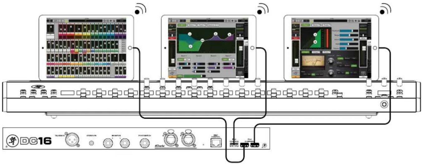
The Smart Bridge is where up to three tablets may be placed for easy viewing and charging purposes. More importantly, tablets placed on the Smart Bridge may be used for control and audio streaming where it automatically detects their presence and enables Following operation modes.
Follow Mode is significant as it allows you to configure and integrate each tablet to behave automatically. Here you're able to view and control three channels simultaneously which leads to a better, faster, more streamlined workflow. What's even cooler is that it's completely customizable: set up the three views that you want integrated!
Also of note is that the tablets look and perform as if they are integrated with DC16. What sets us apart from the "other" guys, though, is that they are integrated... but not permanently. This means that each tablet may be removed for wireless mixing. Simply return the tablet to its spot on the Smart Bridge when not needed wirelessly.
The Follow Mode and Surface to Wireless Mixing features deserve much more than a simple introductory sentence or two. As such, we expand on these items shortly – with a few screen shots, too! – so stay tuned.

A quick note before we fully open this can of worms. As mentioned way, way back, "...the information detailed on the following pages is how to use and control the DC16. There is little to no explanation regarding Master Fader." Well, here we are: the one place where we will dive into Master Fader a bit more! The reason is simple. The Smart Bridge setup occurs within Master Fader (via Settings), but it only applies to the DC16, not DL32R.

As Marty McFly might say, “...this is heavy.” We agree with good ‘ol Marty here and add that it’s a good idea to pay special attention to this, the Smart Bridge section. Don’t worry, we’ll ease you into it.
Listed below is a quick overview of what you can expect over the next few pages, starting at the top with tablet setup.
- Tablet Setup - page 77
- Controllers – page 77
- DC16 Slot - page 77
- Position - page 78
- Follow Mode - page 78
- Follow Mode - page 78
• Current Selected Channel – page 79 - Selected Channel History – page 79
• Fixed View - page 79
• Advanced - page 80
• Surface To Wireless Mixing - page 81
• Examples of Follow Mode - pages 81-85
- Tablet Setup
The first step here is to set up the tablets correctly. As seen in the image on the previous page, the main tablet is located in the center position (connected to the CONTROL USB port on the rear panel of DC16). On either side is a spot for an additional tablet (each connected to a CHARGING USB port, also on the rear panel of DC16).

Please note that each iPad's home button is located on the right hand side. You will almost inevitably run into issues if the home button is on the left hand side. This is due to the design of the iPad. The iPad controls – such as the up/down volume buttons, ringer on/off switch and other controls – are located on the right hand side of the device which won't allow them to "sit" properly in the Smart Bridge.
- Controllers
There is some initial configuration that needs to occur on each tablet placed on the Smart Bridge before moving on to the remaining sections. Each tablet's behavior needs to be configured and this setup takes place within Master Fader in Tools > Controllers. The first thing you should see after opening Tools > Controllers is displayed below.

DC16 Slot:

The DC16 Slot pull-down menu is where you select which DC16 you want the tablet to follow. In most cases, this will either be FOH or MON, but there are two additional choices – slot 3 and slot 4. It should be noted that slot 3 and slot 4 are for more elaborate systems such as those requiring a broadcast desk or two FOH engineers.
The DC16 slot is set up on a per tablet basis.
Position:
Next you need to tell the tablet which position it will be used. Will it be placed on the left, center or right side of the Smart Bridge? As seen in the screen shot on the previous page, the DC16 Slot was set at none. But simply tapping the "A" tablet automatically changes the DC16 Slot from "None" to "FDH: DC16" (although that may be changed via the DC16 Slot pull-down menu). Additionally, the tablet illustration illuminates green indicating that it has been selected.

Each tablet's position is displayed prominently on Master Fader and (as seen below) the DC16 silkscreen has three triangular arrows located in front of the Smart Bridge. Generally speaking, these point to the three spots for each tablet.

natural_image
Pure diagram of a horizontal pipe with three vertical supports and horizontal lines, no text or symbols presentEach of the tablet's positions are set up relatively the same, so retrace the following steps for the other two tablet positions. The first – and really only – step here is to tap each tablet illustration. The next step will be setting up Follow Mode for each tablet.
- Follow Mode
As mentioned earlier, Follow Mode allows you to customize each tablet on the Smart Bridge to behave automatically. Simply configure and integrate the setup you desire, then start mixing! As seen in the screen shot below, there are five Follow Mode selections to choose from, including:

Perhaps the easiest way to understand each of the possibilities is with real-use scenarios. That said, we'll briefly discuss each of these settings then wrap up the entire section with some typical setups.
Current Selected Channel:
As you might have guessed, the Current Selected Channel displays the view of...
...the currently selected channel! In other words, if the tablet is currently displaying the EQ channel view and you rotate the Fat Channel comp thresh encoder, the tablet will change to the dynamics channel view. Similarly, if you're in the FX channel view and you push the 48v button, the tablet will change to the selected channel's input routing view.
It always changes the view (as described above) unless you're adjusting a value in the current view. In other words, let's say that you're in the EQ channel view updating the band I gain. Now push the band 3 button and rotate the Q encoder. You're still on the same channel and same channel view.
Now that you're an expert on Current Selected Channel Follow Mode, you should know that this setup is possible on multiple tablets. Having said that, we can't think of any reason why anyone would set up additional tablets this way. You don't want three of the same view, right?! Here, History, Fixed and/or Advanced is more likely. Please read on...
Selected Channel History:
The Selected Channel History may be likened to a three-month calendar. There will always be three months shown, but only the current month – Current Selected Channel – and two previous months – Selected Channel History – will be displayed. As the months move forward, so do the tablet displays.
With it set up this way, the last channel you were working on – i.e. the previous month, or (now) Selected Channel History – is still easily accessible. Here you're able to jump to another channel to deal with a problem – i.e. current month, or (now) Current Selected Channel – then quickly return to the previous channel you were working on.
For the same reason that you will (most likely) set only one tablet to Current Selected Channel, you probably only want one tablet set to Ist History Selected Channel and the other set to 2nd History Selected Channel (or Fixed or Advanced). Otherwise, you end up with the same view!
Fixed View:
Like the Current and History Follow Modes, Fixed View is somewhat self-explanatory. Tablets that are set to Fixed Mode will stay on the view you desire regardless of the Follow Mode setting on the other tablets. While the view constantly changes on tablets set to Current and History Follow Modes, the view on tablets set to Fixed View won't change at all... until you make the change on the actual tablet.
Fixed View is quite popular around the office and out in the field. For example, a tablet could be Fixed on overview to easily monitor levels and quickly navigate to any channel on the mixer. Or it could be Fixed on the lead vocalist's monitor mix, so you always have access. More detailed examples coming up shortly, so stay tuned!
For optimal performance, Current and History Follow Modes should be set on one tablet each (for reasons mentioned earlier). But multiple tablets could be set to Fixed View, each with different views.
Advanced:
The previously listed Follow Modes will probably be all you ever need or use, but there is an advanced pull-down menu to real dial in a personal Follow Mode based on the selected channel, view and mix, including a Follow Mode selection of 'Do Not Follow'. This reminds me of the lyric, "If you choose not to decide, you still have made a choice." Same idea (sort of), but with different words! Lastly, there is an overview on/off switch that we'll discuss, as well.
When first opened, the Advanced Follow Mode pull-down menu will look something like this:

Here you can see that choosing Advanced Follow Mode opens up four additional pull-down menus, as mentioned above:

Follow Selected CHANNEL

Follow Selected VIEW

Follow Selected MIX
Overview Selects Current [On/Off]
The first three pull-down menus...
- Follow Selected Channel -
- Follow Selected View -
- Follow Selected Mix -
...have the same four options:
- Current Selected -
- Ist History Selected -
- 2nd History Selected -
- Do Not Follow Selected -
This means that each tablet's Follow Mode may be uniquely tailored specifically to your desired configurations based on the channel, view and mix. Options!
The fourth pull-down menu – Overview Selects Current – has two options: On [default] or Off. What this means is that when a tablet is displaying Overview, you can select whether or not any tablets following the current channel go to the selected input(s) or output(s) when touched on the Overview screen. This allows you to view all inputs and outputs (on the Overview screen), then quickly go to the channel(s) needing a quick EQ and/or dynamic adjustment.
If a tablet is set to Fixed View, the Overview Selects Current is automatically set to 'ON'. This way, the Overview remains readily available on that tablet, but the other tablet(s) will go to the selected input(s) or output(s).
Please recall that each tablet is set up separately. For example, since the Overview Selects Current default is set to ON, it needs to be changed on each tablet that you want it set to OFF. This is true of all advanced options... and the options are nearly unlimited... and I'm not about to do the math to figure out how many variations are possible. There's a lot, though, you can count on that!

As a reminder, these advanced parameters will really only be necessary for advanced users needing to tailor the channel, view and mix Follow Modes for specific applications. The non-advanced Follow Modes should be totally fine for most users.
Surface To Wireless Mixing:
The Smart Bridge is called such because... well, because it really is a Smart Bridge! The title of this section is "Surface To Wireless Mixing" and this has everything to do with the Smart Bridge and Follow Mode.
Follow Mode is automatically enabled on tablets that are in position on the Smart Bridge. As stated earlier, the logo illuminates green, too. This is the "surface". When a tablet is removed from the Smart Bridge, though, it is no longer in Follow Mode and the logo is no longer illuminated, either. And this is considered "wireless".

In other words, it senses whether each tablet is in the bridge customizing the tablet's operation for docked or wireless operation. For example, if you need to step onto the stage and ring out a wedge, simply remove a tablet, head up to the stage, adjust the EQ settings referencing the built-in RTA and head back to the mixer when done. When the tablet is placed back in the Smart Bridge, it returns to its last known Follow state automatically and starts following again. This feature dramatically improves workflow and speed any time an adjustment away from the mixer needs to be addressed.

Having said that, this is simply the default setting. Follow Mode is automatically enabled when on the Smart Bridge and automatically disabled when removed from the Smart Bridge. If you want a tablet to remain in Follow Mode when not on The Smart Bridge, simply tap the Follow Mode logo so it illuminates. The opposite is also true: If you do not want a tablet in Follow Mode when on the Smart Bridge, simply tap the Follow Mode logo so it is not illuminated.
Examples of Follow Mode:
Now that you know what Follow Mode is, let's take a look at some use case examples:
The most common setup I've seen (and used) is the following:
Tablet A – Current Selected Channel
Tablet B – 1st History Selected Channel
Tablet C – 2nd History Selected Channel

Here you have the tablet in the center slot – tablet A – displaying the current view of the currently selected channel. Right in front of this tablet are the Fat Channel controls, so everything lines up nicely with all changes taking place right in front of you, dead center.
Once the channel is changed on the DC16 surface on tablet A, it becomes history. This history, though, is still readily available, now on tablet B since it's set to Ist History.
Similarly, once another channel change is made to tablet A [aka the Current Selected Channel], that history becomes readily available on tablet B [aka the Ist History Selected Channel], just as stated above. BUT... what was once on tablet B moves to tablet C since it's set to 2nd History Selected Channel.
This cycle then repeats endlessly with tablet A displaying the current view of the currently selected channel, tablet B displaying what had previously been displayed on tablet A and tablet C displaying what had previously been displayed on tablet B.
Here's a setup that's nearly identical to the previous one, but switched ever-so-slightly. This is how (the previously mentioned) Tom sets up his Follow Mode.
Tablet A - 1st History Selected Channel
Tablet B - Current Selected Channel
Tablet C - 2nd History Selected Channel

He prefers this setup as it's more linear to him, somewhat like an assembly line with the views moving from the far left [tablet B, Current Selected Channel] to the far right [tablet C, 2nd History Selected Channel]. With the tablet Follow Modes set up this way, the Fat Channel controls will change not the tablet in front of it, but rather the tablet in the left slot.
At this point, it's probably a good idea to mess around with these three settings in a variety of methods until you fully grasp what it does, how it works and what it can do for you and your needs. Once understood, we'll move onto Fixed View Follow Mode [super-easy to master] and Advanced Follow Mode [not quite as easy to conceive, but we'll get you dialed in!]
The following is a common setup utilizing the Fixed View Follow Mode.
Tablet A - Current Selected Channel
Tablet B - Fixed View
Tablet C - Fixed View

Here, tablet A is always displaying the current view of the currently selected channel... again, right in front of the Fat Channel controls. And this tablet follows your every move, updating the view and/or channel with a simple touch of a button or turn of an encoder. But tablet's B and C are locked down - fixed - on whatever channel and whatever view you decide. These views will not change no matter how many buttons are touched or encoders are turned. A change will only occur when (A) it's made on the actual tablet or (B) when the tablet's Follow Mode is changed from Fixed View to something else.
A common scenario is setting tablet B's Fixed View to Overview so you have constant visibility of the entire mixer, able to make changes quickly and efficiently. Then tablet C's Fixed View could be placed on an (important) channel's Channel View. A lead vocalist's FX channel, for example. With this configuration, you can touch a channel on the overview and it will be selected on the DC16 surface and tablet A.
One Follow Mode I like to use is this:
Tablet A - Current Selected Channel
Tablet B - Fixed View
Tablet C - 1st History Selected Channel

Here, tablet A is set to the Current Selected Channel, tablet B is set to Fixed View on the Overview and tablet C is set to Ist History Selected Channel taking on the history of whatever was previously viewed on tablet A.
Having said that, the Product Manager and our road warriors prefer a similar setup, but ever-so-slightly different. See below:
Tablet A - 1st History Selected Channel
Tablet B - Current Selected Channel
Tablet C - Fixed View

Here the Overview is Fixed on the right hand side of the Smart Bridge while tablet B is set to the Current Selected Channel and tablet A is set to Ist History Selected Channel taking on the history of whatever was previously viewed on tablet B.
One of our test guys, though, actually prefers to set it up this way:
Tablet A - Current Selected Channel
Tablet B - 1st History Selected Channel
Tablet C - Fixed View

Once again, tablet A is set to the Current Selected Channel. But here, tablet B is set to Ist History Selected Channel taking on the history of whatever was previously viewed on tablet A. Then tablet C is set to Fixed View on the previously mentioned "important" channel's Channel View.
Having said that, this is your mixer and these are your tablets. You can set them up however YOU like. We can just give you examples of how we set them up... and more importantly, why we set them up the way we do.
Now that you're an expert with Current, History and Fixed View Follow Modes, it's time to put the big boy pants on and move onto advanced settings. As mentioned a page or two ago, "The previously listed Follow Modes will probably be all you ever need or use..." and Advanced Follow Mode is "...not quite as easy to conceive, but we'll get you dialed in!"
Perhaps the most common use of the Advanced settings that I've seen around the office and out in the field is what's known as "The Fattest Channel". For now, we'll just look at the first three settings [Follow Selected Channel, View and Mix]. Setup and explanation below:
Tablet A - Follow (Current Channel), Do Not Follow (View), Do Not Follow (Mix)
Tablet B - Follow (Current Channel), Do Not Follow (View), Do Not Follow (Mix)
Tablet C – Follow (Current Channel), Do Not Follow (View), Do Not Follow (Mix)
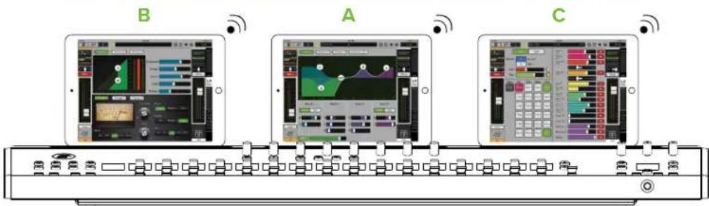
This is the perfect setup to have all processing available on a single channel simultaneously. In other words, one tablet could display a channel's EQ, another a channel's dynamics and the third on input routing view. When a different channel is selected (whether by pushing a SEL button on DC16 or swiping left or right on Master Fader), all three tablets will display the same view as before and all on the same channel... the selected channel! This way you have instant access to that channel's three main Channel Views.
What's even cooler is having a fourth view. But with only three tablets on the Smart Bridge, how can you get a fourth view? Easy! The tablets are already displaying a single channel's EQ, dynamics and input routing, but simply pressing the (SELECTED channel) FX button (located in the upper-left corner of DC16) gives you access to the FX view and controls via the channel displays and encoders.
The example shown below is a variation of the previous setup. We call this one "The Monitor Mix."
Tablet A – Follow (Current Channel), Do Not Follow (View), Do Not Follow (Mix) Tablet B – Follow (Current Channel), Do Not Follow (View), Do Not Follow (Mix) Tablet C – Do Not Follow (Channel), Do Not Follow (View), Follow (Current Mix)

Like the previous setup, tablets A and B will display the selected channel's input processing. Tablet C, however, may be set up to show output processing. Say, an output's GEQ processing with RTA (or Spectrum) or compressor / limiter. From here you can switch between input channels and output mixes without them interfering with one another.
This setup is perfect in that you have instant access to all input channels (as described previously), but tablet C remains constant on GEO, so you can quickly squelch feedback regardless of the selected input. Additionally, you can switch between outputs [mixes] without it changing the selected input.
But wait, there's more! While the DCIG Smart Bridge has three follow mode switches, each with their own Follow Modes, there is a fourth wireless position - "N" - that may be established with its own Follow Mode, as well.
This device will be tied to dock position "N," but won't be tied to a smart bridge switch, so it can always follow DC16 moves on the fly. This is ideal for computers that may be next to DC16, although tablets and phones also work. The choice is yours and it's (almost) unlimited! Be sure to tap the "N" near the upper-left corner of the tablet to engage (illuminates green) or disengage (gray).
SETUP Button (ALT + DYN)
This button selects and displays the initial setup controls and a few other goodies!

These settings are not stored as snapshots. They will remain where you leave them, regardless of the selected snapshot (including the default snapshot 0). They are actually stored in the DL32R for the associated slot. So if you change DC16s, the slot retains the settings and the new DC16 will come up just like the old one. More about slots below.
The DYN button's LED illuminates white when engaged.
When Setup is selected, the channel displays on the first page offer the following options:

flowchart
graph TD
    A["Setup"] --> B["Connected To DL32R FOH"]
    B --> C["Screen Brightness Sun"]
    C --> D["Button Brightness Mid"]
    D --> E["Meter Brightness Low"]
    E --> F["Lamp Brightness OffChan ?"]
    F --> G["Stereo Source Analog"]
    B --> H["Talkback Mode Auto"]
    H --> I["Access Limits Change?"]
    I --> J["Calibrate Faders? Do it!"]
    J --> K["About Tell me!"]
Connected To DL32R Slot X:
This lists the currently connected mixer and slot. If you want to change it, press the encoder below "Change?"
Here you'll see an entry for each DL32R on the system. Each DL32R will be labeled the custom name you gave it [default is DL32R]:
DL32R - Select
Refresh Mixer list - Do it!
Exit

Renaming the DL32R has already been described in detail in the Master Fader Reference Guide (in the Tools > Devices section), but did you know that each DC16 may be named, as well? It is done the same exact way, but for DC16. Doing so requires a fast (and automatic) reboot.
Additional information about slots was discussed previously on page 10.
Screen Brightness:
How bright do you want the channel displays? Press or rotate the encoder until you see the choice you prefer between:
Low
Mid
High [Default]
Sun – The “Sun” setting adds a high contrast mode so the screen brightness is even more legible when the DC16 is used in direct sunlight at outdoor venues.

When in Sun mode, all channel screens, group selectors and mix selectors on DC16 will be displayed in black and white only, no colors!
Button Brightness:
How bright do you want engaged buttons? Press or rotate the encoder until you see the choice you prefer between:
Low
Mid
High [Default]
Meter Brightness:
How bright do you want the meters? This includes the gain reduction LEDs, level meter LEDs and mix select LEDs. Press or rotate the encoder until you see the choice you prefer between:
Low
Mid
High [Default]
Lamp Brightness:
Do you have a lamp connected to the rear panel lamp connector? If so, how bright do you want the lamp? Press or rotate the encoder until you see the choice you prefer between:
Off
Low
Mid
High [Default]
Stereo Source:
Will the stereo input source be the analog I/8" input or do you prefer to use the iPad for USB playback? Press or rotate the encoder until you see the choice you prefer between:
Analog [Default]
iPad
Once the stereo source has been selected, you might need to set up the routing path. But if you already selected to auto-route Dante, then there won't be anything to do! This is because your sources and destinations have already been set up.
Additional information about Dante was discussed previously on pages 10-16.
Talkback Mode:
What talkback mode do you prefer? Press or rotate the encoder until you see the choice you prefer between:
Latch – Talkback is on when the talkback button is pressed and released. Press and release again to disengage talkback.
Momentary – Talkback is on when the talkback button is pressed and held, then simply let go to disengage talkback.
Auto - The talkback button (and functionality) is automatic, depending on if you tap and release [latching] or tap and hold [momentary] the talkback button.
Access Limits:
Access limits allows you to limit access to a variety of controls. When the Access Limits encoder is engaged, the channel displays on the first page offer the following options:


Use the up and down flip arrows to access the other parameters that may be access limited.
Page 2: FX, Subgroups I-6 and VCAs I-6
Page 3: Matrices I-6, Input/Output DSP and Routing, Mic Preamps, Pan and Show
Page 4: View Groups, Mute Groups, CHAN, User Buttons, User Encoders, Assign, Lock, Master, Mute, Solo,
Devices, Setup and Transport
Page 5: Set all limits on/off?
The description of the majority of these parameters may be reviewed in the Master Fader Reference Guide. Parameters that may be access limited on the actual DC16 include the buttons and encoders. These parameters will obviously not be physically removed from sight, but they will be locked from use if access limited.
All parameters listed may be accessed or access limited simply by pressing the adjacent encoder. Press the Exit encoder to return to the main setup view.
Calibrate Faders:
This is simply the place to calibrate the faders. Press the encoder to begin fader calibration. The channel display will present "In progress..." during fader calibration and "Do it!" when finished. When wrapped up, the faders will return to the position they were in prior to calibration. The entire process should only take approximately 10 seconds.

This feature should only be used if the faders aren't moving or aren't accurately representing their positional value. Make sure that the faders are not obstructed during calibration and do not touch them during calibration.
About:
This is the place to view the settings of this particular DCI6. Press the encoder to display similar settings as seen below. Press the "Cancel" encoder when you are finished with this view.

The channel displays on the second page of the setup menu, though, offer the following options:

flowchart
graph TD
    A["Setup"] --> B["DC16 Follows MF Select"]
    B --> C["On"]
    B --> D["On"]
    B --> E["On"]
    B --> F["Off"]
    F --> G["Lock Inputs"]
    G --> H["Left"]
    G --> I["Lock Outputs"]
    I --> J["Right"]
    J --> K["Show Locked Channels in View Groups"]
    K --> L["Off"]
    K --> M["Show Locked Mixes in Mix Selector"]
    M --> N["Off"]
    M --> O["Auto Spill Locked Mixes"]
    O --> P["Off"]
Just as Master Fader can follow the moves of DCI6, the DCI6 can also follow the moves of Master Fader. Here we've provided preferences the user can set and tell DCI6 whether or not to follow certain changes from Master Fader when follow mode is engaged. This allows you to navigate to places in Master Fader without DCI6 being affected. They are:
DCI6 Follows MF Select:
Touching a fader in Master Fader selects a channel. Do you want DC16 to reflect that channel selection? Or would you prefer DC16 to not follow? Press or rotate the encoder until you see the choice you prefer between:
On [Default] Off
DCI6 Follows MF View:
When navigating Master Fader to a channel view, the DCI6 will follow those moves if follow mode is engaged. Or would you prefer the DCI6 not to change when navigating channel views in Master Fader? Press or rotate the encoder until you see the choice you prefer between:
On [Default] Off

If DC16 Follows MF Select is turned off, then DC16 Follows MF View will be "grayed out" and unavailable.
DC16 Follows MF Mix Select:
When you're standing next to the musician on stage dialing in their monitor mix with a wireless tablet, do you want to return to the DC16 at the FOH position only to find the mix selector has been following the tablet this whole time? Or would you prefer the DC16 not to follow the Mix Select movements of Master Fader when wandering about wirelessly? Personally, I like to leave the DC Mix Selector on LR Main, so that I return to DC16 without having to navigate. Press or rotate the encoder until you see the choice you prefer between:
On [Default]
Off
Sel Follows Input Solo:
When you solo an input channel, do you want that channel to also be selected? If so, then you will want this feature set to on. The most recently soloed channel will be the currently selected input channel. Press or rotate the encoder until you see the choice you prefer between:
On Off [Default]
Sel Follows Input Fader:
When you move an input fader, do you want that channel to also be selected? If so, then you will want this feature set to on. The last touched input fader will also be the currently selected channel. Press or rotate the encoder until you see the choice you prefer between:
On Off [Default]
Sel Follows Output Solo:
When you solo an output, do you want that output to also be selected? If so, then you will want this feature set to on. The last soloed output will also be the currently selected output. Press or rotate the encoder until you see the choice you prefer between:
On Off [Default]
Sel Follows Output Fader:
When you move an output fader, do you want that output to also be selected? If so, then you will want this feature set to on. The last touched output fader will also be the currently selected output. Press or rotate the encoder until you see the choice you prefer between:
On Off [Default]
Lock Inputs:
When channel inputs are locked, do you want them locked to the left or right side of the mix deck? Press or rotate the encoder until you see the choice you prefer between:
Left [Default]
Right

Inputs and outputs may both be locked to one side of the mix deck. If both are locked to the left side, the inputs will be on the far left with the outputs next to the inputs. On the far right will be the remaining (unlocked) channels. Bank over to view the other unlocked channels. If both are locked to the right side, though, the inputs will still be on the left with the outputs next to the inputs, but it will be shifted over to the right of the mix deck. On the far left will be the remaining (unlocked) channels. Bank over to view the other unlocked channels.
More information about locked channels may be found on pages 72-75.
Lock Outputs:
When outputs are locked, do you want them locked to the left or right side of the mix deck? Press or rotate the encoder until you see the choice you prefer between:
Left Right [Default]
Inputs and outputs may both be locked to one side of the mix deck. If both are locked to the left side, the inputs will be on the far left with the outputs next to the inputs. On the far right will be the remaining (unlocked) channels. Bank over to view the other unlocked channels. If both are locked to the right side, though, the inputs will still be on the left with the outputs next to the inputs, but it will be shifted over to the right of the mix deck. On the far left will be the remaining (unlocked) channels. Bank over to view the other unlocked channels.
More information about locked channels may be found on pages 72-75.
Show Locked Channels in View Groups:
When channels are locked, do you want them visible when a view group is selected? If so, then you will want this feature set to on. Then all channels disappear from the mix deck except for the locked channels. Press or rotate the encoder until you see the choice you prefer between:
Off [Default]
More information about locked channels may be found on pages 72-75.
Show Locked Mixes in Mix Selector:
Locked mixes may either be shown or hidden from the mix selector. Press or rotate the encoder until you see the choice you prefer between:
On – The mix selector will show the locked mixes, but will also display a single version of those outputs, as well. Off [Default] – The mix selector does not show doubles of the locked mixes.
More information about locked mixes may be found on page 75.
Auto Spill Locked Mixes:
Locked mixes may be "auto spilled" to the mix deck via single or double-tap of a SEL(ect) button. Press or rotate the encoder until you see the choice you prefer between:
On - A single tap of the locked output's SEL(ect) button will clear the mix deck of everything except the assigned inputs.
Off [Default] - A double-tap of the locked output's SEL(ect) button will clear the mix deck of everything except the assigned inputs.
More information about auto spilling locked mixes may be found on page 74.
The channel displays on the third and final page of the setup menu offers the following options:

flowchart
graph LR
    A["Setup"] --> B["Auto return from selected channel editing"]
    B --> C["Hide names in selected channel editing"]
    C --> D["Select Next Snapshot After Recall OffOff20"]
    D --> E["Require Confirmation for Snapshot Recall on"]
    E --> F["Meter Peak Hold Fast"]
    F --> G["Meter Clip Hold Really Slow"]
    G --> H["SOLO Mode StartMultiple"]
    H --> I["SOLO Location"]
Auto return from selected channel editing:
This is a handy feature that allows you to stay on the most important – to you – ALL channel editing function after you've made some quick SELECTED channel edits.
Ok, I know what you're thinking; it probably goes something like "Well, that sounds confusing!" No worries, it's easy to understand... especially with an example!
- Start by rotating the encoder so it displays "10 sec".
- Next, make GAIN the currently selected (ALL) channel editor.
- Now, press a (SELECTED) channel editing button, like EQ or DYN, make a few changes, then do nothing.
- Channel editing will return back to GAIN 10 seconds after your last edit, showing you the full names, colors and icons for easy channel identification.
A few notes regarding this example:
First, 10 seconds was selected for the example. Feel free to rotate the encoder until you see the choice you prefer between:
Off [Default]
10 sec
20 sec
30 sec
40 sec
50 sec
60 sec
The default [Off] just means that there is no auto return to SELECTED channel editing. DCI6 follows your every move and stays where you leave it.
Second, any of the available ALL channel editing selections may be chosen (including most ALT + selections).
Speaking of which – third – any of the available SELECTED channel editing selections may be chosen (including Sends (ALT + GEO)).
More information about channel editing may be found on pages 47-62.
Hide channel names in selected channel editing:
By default, when a SELECTED channel editing mode is selected, the channel's names and numbers are presented in the channel display along with the editing mode characteristics. However, if you would prefer the channel names and numbers not be there – only displaying the editing mode characteristics – simply change this setting to "On".
Rotate the encoder until you see the choice you prefer between:
On Off [Default]
See below for the same exact example of this feature, one with OFF selected and one with ON selected. Notice the difference between the two. The choice really comes down to if you want input and output names and channels displayed or not. Displayed certainly makes it easier to see what bank you're on (and what channels are on them), but hiding them may make it easier to focus on the editing parameters. Regardless of your choice, inputs and outputs may be selected as always with the selected channel display showing your selection.

Select Next Snapshot After Recall:
Would you like DC16 to select the next snapshot after recall? Press or rotate the encoder until you see the choice you prefer between:
On – After a snapshot is loaded, the highlighted snapshot will be the next snapshot of the show (until manually changed).
Off [Default] – After a snapshot is loaded, the highlighted snapshot remains the currently loaded snapshot (until manually changed).
Require Confirmation for Snapshot Recall:
Would you prefer to have an extra level of security when loading up another snapshot? If so, then you will want this feature set to on. Once you press (and release) the 'Recall' button, it will flash for approximately five seconds. You will need to press the button again to confirm recall. If not pressed again, it will remain on the same (current) snapshot. Press or rotate the encoder until you see the choice you prefer between:
On Off [Default]

Please be aware! If you press and hold the 'Recall' button, the snapshot will load. This feature only works when you press and release the 'Recall' button.
Meter Peak Hold:
What meter peak hold speed do you prefer? Press or rotate the encoder until you see the choice you prefer between:
Off
Slow - 6 seconds
Fast - 2 seconds
Meter Clip Hold:
What meter clip hold speed do you prefer? Press or rotate the encoder until you see the choice you prefer between:
Really Slow - 6 seconds
Slow - 3 seconds
Fast - 2 seconds
SOLO Mode:
What solo mode do you prefer? Press or rotate the encoder until you see the choice you prefer between:
Single - Only one input or output may be soloed at a time. Soloing a second channel will un-solo the previous channel.
Multiple [Default] - Solo as many inputs or outputs as you desire!
Multi-Inputs - Solo as many inputs as you desire, but once an output is soloed, all soloed input channels are cleared.
SOLO Location:
Solo Location is a feature that allows you to select if the solo location is PFL, AFL or Smart. The Smart setting is PFL for inputs and AFL for outputs.
Press or rotate the encoder until you see the choice you prefer between:
PFL
AFL
Smart (PFL for inputs and AFL for outputs) [Default]
By default, input channel solo buttons are PFL which stands for pre-fader listen.
Therefore, the level of the channel fader DOES NOT affect the level heard in the monitor bus.
BUT... solo location may be changed to AFL (which stands for after-fader listen (and the level of the channel fader DOES affect the level heard in the monitor bus)).
Solo is also post-DSP, so if a soloed channel's EQ, compressor or gate is engaged, the processed settings will be heard. But, solo is unaffected by the position of the mute button.
Chapter 6 : DC16 Tips and Tricks
Subgroup / VCA Mix Spill
The channel displays present all I6 input channels simultaneously with accompanying ID information, but what if you wanted to view and update only the input channels assigned to a subgroup or VCA? Here is a really neat trick to be able to just that!
Let's start with a pretty common setup: drums. In the majority of cases, multiple channels will be drum tracks.
As one might imagine, workflow is a lot easier when all of these input channels are assigned to a single subgroup or VCA.
My channel displays currently looks something like this (with the drums routed to subgroup I):

What's not shown, though, are the remaining channels. Multiple channels dedicated to bass, guitars, keyboards, a horn section, vocals and more. It can be confusing if the only parameters you want to update are the drums. This is an easy solution to "hide" the other channels from the channel display.
Simply bank over until subgroup I is visible in the channel displays. Double-tap the subgroup I SEL(ect) button.
Voilà! Just like that, any channel not routed to subgroup I disappears from the channel displays, leaving only the drums (in this example).
Furthermore, if you take a look over at the mix selector, you will notice that subgroup I is at the top of the mix and the subgroup I SEL(ect) button is selected and illuminated.
This tip works with all subgroups and VCAs so long as it has at least one input channel assigned to it.
To leave the subgroup / VCA mix spill just double-tap the output SEL(ect) button to return to the previously selected mix.
Appendix A: Hookup Diagram
Live Sound: House Engineer
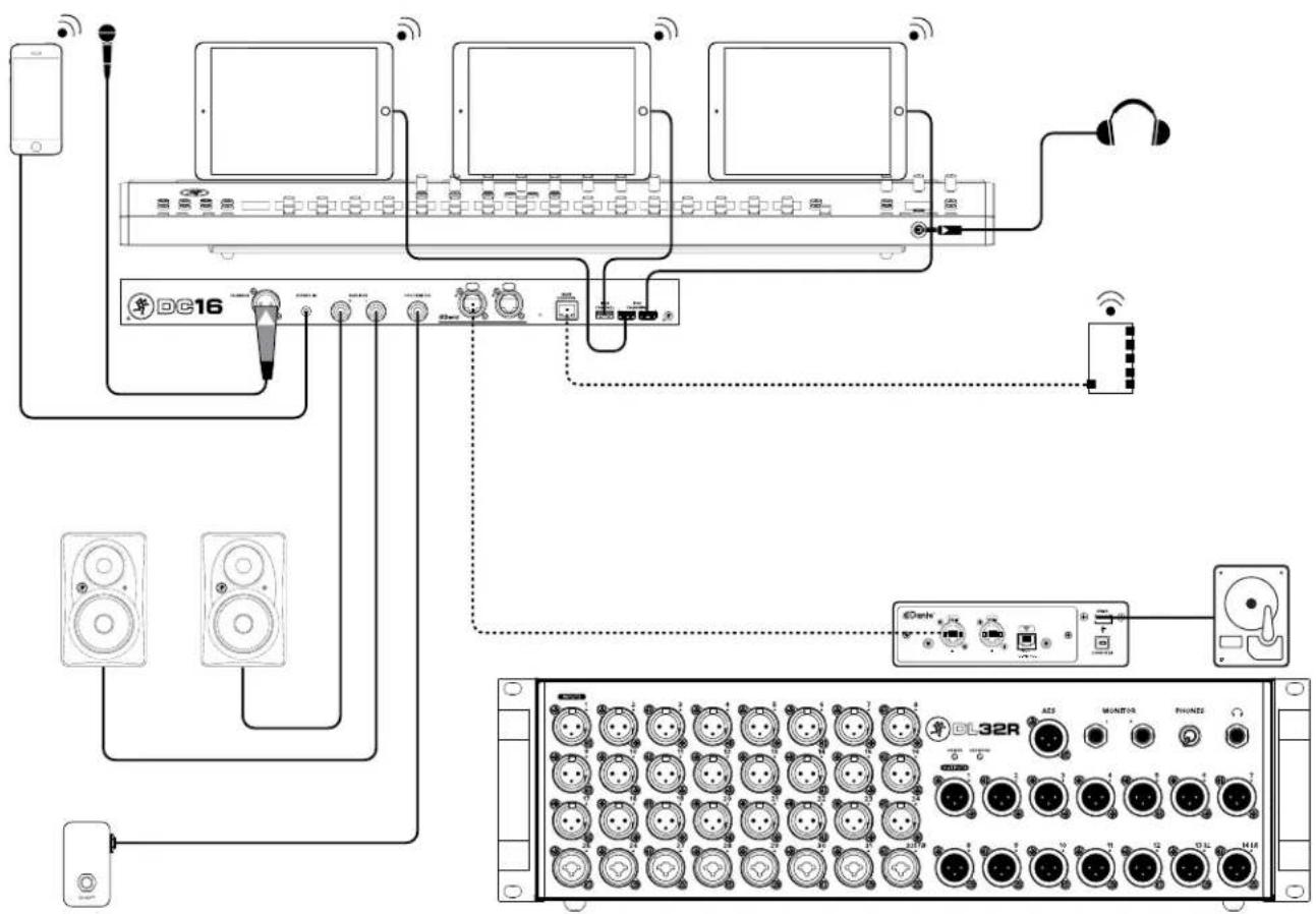
flowchart
graph TD
    A["Smartphone"] --> B["DC16"]
    C["Speaker 1"] --> B
    D["Speaker 2"] --> B
    E["Speaker 3"] --> B
    F["Speaker 4"] --> B
    G["Speaker 5"] --> B
    H["Speaker 6"] --> B
    I["Speaker 7"] --> B
    J["Speaker 8"] --> B
    K["Speaker 9"] --> B
    L["Speaker 10"] --> B
    M["Speaker 11"] --> B
    N["Speaker 12"] --> B
    O["Speaker 13"] --> B
    P["Speaker 14"] --> B
    Q["Speaker 15"] --> B
    R["Speaker 16"] --> B
    S["Speaker 17"] --> B
    T["Speaker 18"] --> B
    U["Speaker 19"] --> B
    V["Speaker 20"] --> B
    W["Speaker 21"] --> B
    X["Speaker 22"] --> B
    Y["Speaker 23"] --> B
    Z["Speaker 24"] --> B
    AA["Speaker 25"] --> B
    AB["Speaker 26"] --> B
    AC["Speaker 27"] --> B
    AD["Speaker 28"] --> B
    AE["Speaker 29"] --> B
    AF["Speaker 30"] --> B
    AG["Speaker 31"] --> B
    AH["Speaker 32"] --> B
    AI["Speaker 33"] --> B
    AJ["Speaker 34"] --> B
    AK["Speaker 35"] --> B
    AL["Speaker 36"] --> B
    AM["Speaker 37"] --> B
    AN["Speaker 38"] --> B
    AO["Speaker 39"] --> B
    AP["Speaker 40"] --> B
    AQ["Speaker 41"] --> B
    AR["Speaker 42"] --> B
    AS["Speaker 43"] --> B
    AT["Speaker 44"] --> B
    AU["Speaker 45"] --> B
    AV["Speaker 46"] --> B
    AW["Speaker 47"] --> B
    AX["Speaker 48"] --> B
    AY["ACS"] --> AZ["MONITOR"]
    AZ --> BA["FHUNDS"]
    BA --> BB["MUX"]
    BB --> BC["MONITOR"]
    BC --> BD["FHUNDS"]
    BD --> BE["MUX"]
    BE --> BF["MUX"]
    BG["MUX"] --> BH["MUX"]
    BI["MUX"] --> BJ["MUX"]
    BK["MUX"] --> BL["MUX"]
    BM["MUX"] --> BN["MUX"]
    BO["MUX"] --> BP["MUX"]
    BP["MUX"] --> BQ["MUX"]
    BR["MUX"] --> BS["MUX"]
    BS["MUX"] --> BT["MUX"]
Here's a pretty common setup utilizing the full Axis system.
DC16 Front and Top Panels:
* Three iPads placed on the Smart Bridge.
* Pair of headphones connected to the phones jack.
DC16 Rear Panel:
* Mic connected to the Talkback jack.
* Smart phone or MP3 player connected to the stereo input jack.
* Pair of HRmk2 Series monitors connected to the L/R monitor jacks.
* One-button footswitch connected to the footswitch jack.
* Ethernet cable from the router to the Wi-Fi Control jack.
* Lightning cables from the Control and Charging jacks connected to the three iPads.
* Ethernet cable from the Dante jack on DC16 to the Dante jack on the DL32R.
DL32R Front Panel:
* I-24 XLR cables connected to inputs I-24.
* I-8 XLR or I/4" cables connected to inputs 25-32.
* I-14 XLR cables connected to outputs I-14.
DL32R Rear Panel:
* Ethernet cable from the Dante jack on the DL32R to the Dante jack on DC16.
* Hard drive OR computer connected to one of the USB outputs.
Appendix B : Technical Information
Specifications
General Digital
Sample Rate: 48 kHz
A/D/A Bit Depth: 24-bit
O dBFS Reference: +22 dBu
Frequency Response
All inputs to all outputs: ....±0, -1 dB, 20 Hz to 20 kHz
Stereo Input
Connector: I/8" Unbalanced
Input Impedance: 10 kΩ
Max Input Level:....+16 dBu
Talkback Mic
Connector: XLR Balanced
XLR Mic Pre:......Onyx
Input Impedance: 3 kΩ
Max Input Level:....+2I dBu
Gain: 0 - 60 dB
Analog Monitor Outputs L/R
Connectors:.... I/4" TRS Impedance Balanced
[Supports balanced / unbalanced operation]
Output Impedance: 240 Ω Balanced,
120 Ω
Max Output Level: ....+21 dBu
Analog Headphone Out
Connector: I/4" TRS Stereo
Max Output Level: +18 dBu into 600 Ω
+19.5 dBu max into 100 k
Ω
Specifications Continued...
DC16 iPad Connectivity
Connection: USB-A for Lightning iPads
Connectors:....lx USB-A (Control, audio and charging)
2x USB-A (Charging only) Control: Full Control Audio: Digital streaming, 2 in / 2 out, 44.1 kHz / 48 kHz, 16-bit / 24-bit
Networking
Connection: Gigabit Ethernet
Dante
Connection:....2x etherCon Gigabit Ethernet
Sample Rate: 48 kHz
Bit Depth: 24-bit
Transmit / Receive Channels: 4 / 4
Supports Dante Switch modes Configuration via Dante Controller
Supported Devices
iOS Version Requirement: iOS II.0 or higher
Android Version Requirement: v7.0 or higher
macOS Version Requirement:....macOS 10.12 or higher
Windows Version Requirement: Windows 10
Control Application: ......Mackie Master Fader App
Requires Master Fader V5.2
[For optimal performance and latest feature set,
we suggest using the latest Master Fader app]
Specifications Continued...
Power
| Power Consumption: | 102 watts |
| External Supply | |
| Power Requirements: | 100 VAC - 240 VAC, 50 - 60 Hz |
| Universal Supply | |
| Output Voltage: | 12 VDC |
| Current: | 8.5A |
| Connector: | Locking Multi-Pin Connector |
| Power Cord: | User-replaceable IEC |
| Operating Temperature | 0 - 40 °C |
| [extended ambient temperature]: | 32 - 104 °F |
Accessories
| DC16 Road Case: | P/N 2044370 |
| DC16 Cover: | P/N 2036849-42 |
| 80m Cat5e Reel: | P/N 2043430-080 |
| DL32R Install Rackmount Kit: | P/N 2042160 |
Dimensions
| Height: | 3.3 in / 84 mm |
| Width: | 36.8 in / 935 mm |
| Depth: | 17.6 in / 447 mm |
| Weight: | 38.0 lb / 17 kg |
About
Part Number, Rev and Date: SWII24, Rev B, August 2020
©2020 LOUD Audio, LLC. All rights reserved. Apple, iPad, iPhone and iPod touch are trademarks of Apple Inc., registered in the U.S. and other countries. All other marks are Registered Trademarks, or Trademarks, of LOUD Audio, LLC. in the United States and other countries. DC16 and DL32R Patent Pending.
"Made for iPad" means that an electronic accessory has been designed to connect specifically to iPad and has been certified by the developer to meet Apple performance standards. Apple is not responsible for the operation of this device or its compliance with safety and regulatory standards. Please note that the use of this accessory with iPad may affect wireless performance.
LOUD Audio, LLC. is always striving to improve our products by incorporating new and improved materials, components, and manufacturing methods. Therefore, we reserve the right to change these specifications at any time without notice.
Please check our website for any updates to this Reference Guide: www.mackie.com.
DC16 Dimensional Drawings
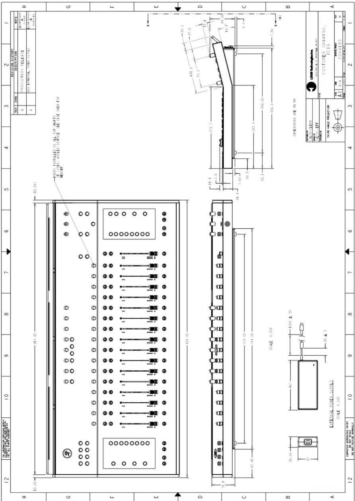
DC16 Dimensional Drawings Continued...

Appendix C : Service Information
Troubleshooting
If you think your DC16 has a problem, please check out the following troubleshooting tips and do your best to confirm the problem. Visit the Support section of our website (www.mackie.com/support) to get some ideas or contact our technical support heroes. You may find the answer to the problem without having to send your DC16 away.
Here are three useful tips that could correct any of the issues outlined below (or possibly any other issue that we haven't yet discovered):
(I) — Restart the iPad. Don't just restart the Master Fader app. Restart the iPad! Completely power it down, then power it back up.
(2) — Restart the DC16 and DL32R. This is especially useful after firmware and software updates where the mixer and iPad aren't quite on the same page. A simple reboot can sometimes work great wonders.
(3) — Restart the router. Internet disconnectivity got you down? Unplug and re-plug the router. This may resolve any connection issues.
There are no user serviceable parts. If none of these tips work, please refer to "Repair" on the next page to find out how to proceed.
No Power
- Our favorite question. Is it plugged in? Make sure the AC outlet is live [check with a tester or lamp].
- Our second favorite question. Is the rear panel power switch in the ON position?
- Are all the lights out in town? If so, contact the local power company to get power restored.
No Sound
- Are all the connections good and sound? Make sure all of the connecting cables work and are securely connected at both ends. Try the same source signal in another channel, set up exactly like the suspect channel.
- Is the signal source powered on? Is it working (and making union scale)?
Noise / Hum
- Are all the connections good and sound? Make sure all of the connecting cables work and are securely connected at both ends. Try the same source signal in another channel, set up exactly like the suspect channel.
- Are you using unbalanced cables? Swap them out with balanced cables to see if that fixes the problem.
- Turn the input gains down one-by-one. If the offending noise disappears, it's either that input or whatever is plugged into it. If you unplug the whatever-is-plugged-into-it and turn the input gain back up and the noise is gone, it's from your whatever.
• Is phantom power required for the microphone?
• Sometimes it helps to plug all the audio equipment into the same AC circuit so they share a common ground. Make it so. - Has the band been together long?
Dante Difficulties?
• We took time writing up a Dante Setup Guide. Check it out HERE 1!
- There is a massive amount of information on the Audinate website. Check it out HERE ^2 !
No Interwebs
- Read the chapter titled "Wireless Setup" in the Master Fader Reference Guide.
This section is very important and reading it cover-to-cover is the best troubleshooting. - Is your iPad connected to the correct wireless network? Go to iPad Settings > Wi-Fi and ensure that it didn't hop onto to a different wireless network.
- Did you select the wireless DL32R from the tools > devices screen?
- Are you running the latest and greatest master fader and DL Series firmware? Go to the App Store and check for an update.
• Did you connect the Ethernet cable to the correct port on the router? Be sure to use the LAN port and not the WAN port. - Did you connect and then power on the Wi-Fi router BEFORE turning on the DC16 / DL32R?
- Leave Master Fader and then return by pressing the Home button on the iPad.
• Force quit the Master Fader app. - Try another Ethernet cable.
- Try another Wi-Fi router.
Repair
For warranty service, refer to the warranty information on page 104.
Non-warranty service for our products is available at a factory-authorized service center. To locate the nearest service center, visit www.mackie.com/support. Service for our products living outside the United States can be obtained through local dealers or distributors.
If you do not have access to our website, you can call our Tech Support department at I-800-898-32II, Monday-Friday during normal business hours, Pacific Time, to explain the problem. Tech Support will tell you where the nearest factory-authorized service center is located in your area.
Warranty Statement
Please keep your sales receipt in a safe place.
This Limited Product Warranty (“Product Warranty”) is provided by LOUD Audio, LLC. (“LOUD”) and is applicable to products purchased in the United States or Canada through a LOUD-authorized reseller or dealer. The Product Warranty will not extend to anyone other than the original purchaser of the product (hereinafter, “Customer,” “you” or “your”).
For products purchased outside the U.S. or Canada, please visit www.mackie.com/warranty to find contact information for your local distributor, and information on any warranty coverage provided by the distributor in your local market.
LOUD warrants to Customer that the product will be free from defects in materials and workmanship under normal use during the Warranty Period. If the product fails to conform to the warranty then LOUD or its authorized service representative will at its option, either repair or replace any such nonconforming product, provided that Customer gives notice of the noncompliance within the Warranty Period to the Company at: www.mackie.com/support or by calling LOUD technical support at 1.800.898.32II (toll-free in the U.S. and Canada) during normal business hours Pacific Time, excluding weekends or LOUD holidays. Please retain the original dated sales receipt as evidence of the date of purchase. You will need it to obtain any warranty service.
For full terms and conditions, as well as the specific duration of the Warranty for this product, please visit www.mackie.com/warranty.
The Product Warranty, together with your invoice or receipt, and the terms and conditions located at www.mackie.com/warranty constitutes the entire agreement, and supersedes any and all prior agreements between LOUD and Customer related to the subject matter hereof. No amendment, modification or waiver of any of the provisions of this Product Warranty will be valid unless set forth in a written instrument signed by the party to be bound thereby.
GPL Statement
This product includes software code developed by third parties, including software code subject to the GNU General Public License ("GPL") Version 2. Where such specific license terms entitle you to the source code of such software, LOUD Audio, LLC. will provide upon written request via email or traditional paper mail the applicable GPL source code files via CD-ROM for a nominal cost to cover media, shipping and handling charges as allowed under the GPL.
The GPL code used in this product is distributed WITHOUT ANY WARRANTY and is subject to the copyrights of one or more authors. For details, see the GPL code and the terms of the GPL. For a copy of the GPL please write to the Free Software Foundation, Inc., 51 Franklin Street, Fifth Floor, Boston, MA 02110-1301, USA.
Please direct all GPL Source Requests to the following email/address.
Attn: GPL Source Request
LOUD Audio, LLC.
19820 North Creek Parkway #201
Bothell, WA 980II
or
www.mackie.com/support-contact

natural_image
White stick figure running inside a circle on black background (no text or symbols)19820 North Creek Parkway #201, Bothell, WA 98011 • USA
Phone: 425.487.4333 • Toll-free: 800.898.3211
Fax: 425.487.4337 • www.mackie.com

MACKIE.
SOUND LIKE YOU MEAN IT


- DC16
- OWNER'S MANUAL
- Important Safety Instructions
- Table of Contents
- Groups Selector 27
- Mix Selector 37
- Channel Editing......47
- All Channel Editing
- Selected Channel Editing
- Fat Channel 63
- Snapshot Control......66
- Analog Controls 68
- Modifiers 69
- Chapter 1: Welcome
- About This Guide
- Chapter 2: Getting Started
- Chapter 3: A Closer Look at Slots and Dante
- Introduction
- Slots
- FOH
- MON
- Dante
- Why Use Dante?
- Dante Routing
- Stereo Source
- Other Dante Routing
- Chapter 4: DC16 Front and Rear Panels
- Front Panel Introduction
- Phones Jack
- Rear Panel Introduction
- Talkback Mic Input
- 1/8" Stereo In Jack
- 1/4" Monitor L/R Outputs
- 1/4" Footswitch Jack
- Dante A / B
- -Force Update Button
- Wi-Fi Control
- Tablet Control and Charging USB Inputs
- Power Connector
- Power Switch
- Lamp Input Jack
- Chapter 5: DC16 Top Panel
- Top Panel Introduction
- Input Channels / Master Channel
- - SEL (Select) Buttons
- - MUTE Buttons
- • 100 mm motorized touch sensitive faders
- - Gain Reduction LEDs
- - Level Meter LEDs
- - Mix Select LEDs
- SOLO Buttons
- Channel Screens Overview
- • Channel Displays and Encoders
- Editing Page Buttons
- Banking Group Selector
- - BANK Buttons
- - CHANNEL Buttons
- Groups Selector
- VIEW Group Button
- MUTE Group Button
- USER Button
- CHAN(nel) Button
- Mix Selector
- Page Buttons
- Master Fader DC16: LR - A6 [Page 1]
- DefaultDefault Customized
- MAST(er) Button
- LOCKOUT MODE
- CLEAR SOLO Button
- TALK(back) Button
- Channel Editing
- ALL Channel Editing - top row BUTTONS (left to right):
- SELECTED Channel Editing - bottom row BUTTONS (left to right):
- GAIN Button
- TRIM Button (ALT + GAIN)
- - HPF Button
- - LPF Button (ALT + HPF)
- - SEND Button
- L/R Fader / Pan on Per Channel Sends
- DELAY Button (ALT + SEND)
- PAN Button
- USER Button (ALT + PAN)
- NORMAL MODE
- USER MODE
- EQ Button
- ASSIGN Button (ALT + EQ)
- GEQ Button
- SENDS Button (ALT + GEQ)
- DYN(amics) Button
- SETUP Button (ALT + DYN)
- FX Button
- TRANS(port) Button (ALT + FX)
- Fat Channel
- GAIN Encoder
- TRIM Encoder (ALT + GAIN)
- 48v Phantom Power Button
- Polarity Invert [∅] Button
- HPF Encoder
- LPF Encoder (ALT + HPF)
- • Four-band Parametric EQ Buttons and Encoders [GAIN, FREQ, Q]
- GATE THRESH Encoder
- GATE RANGE Encoder (ALT + GATE THRESH)
- COMP THRESH Encoder
- COMP RATIO Encoder (ALT + COMP THRESH)
- PAN Encoder
- DELAY Encoder (ALT + PAN)
- Snapshot Control
- • Display
- ARROW Buttons
- RECALL Button
- STORE Button
- MORE Button
- Analog Controls
- • TALKBACK Knob
- • MONITOR Knob
- - PHONES Knob
- Modifiers
- ALT Button
- ALT Button + Channel Editing Button:
- ALT Button + Fat Channel Encoder:
- SHIFT Button
- ASGN Button
- Assign Mode:
- View Group E view group Song IV
- Mute Group 3 Song II
- Assign Mode: Talkback
- LOCK Button
- Assign Mode: Channel Lock
- Smart Bridge
- - Tablet Setup
- - Controllers
- Position:
- - Follow Mode
- Current Selected Channel:
- Selected Channel History:
- Fixed View:
- Advanced:
- Surface To Wireless Mixing:
- Examples of Follow Mode:
- Tablet A - 1st History Selected Channel
- Tablet A - Current Selected Channel
- Connected To DL32R Slot X:
- Screen Brightness:
- Button Brightness:
- Meter Brightness:
- Lamp Brightness:
- Stereo Source:
- Talkback Mode:
- Access Limits:
- Calibrate Faders:
- About:
- DCI6 Follows MF Select:
- DCI6 Follows MF View:
- DC16 Follows MF Mix Select:
- Sel Follows Input Solo:
- Sel Follows Input Fader:
- Sel Follows Output Solo:
- Sel Follows Output Fader:
- Lock Inputs:
- Lock Outputs:
- Show Locked Channels in View Groups:
- Show Locked Mixes in Mix Selector:
- Auto Spill Locked Mixes:
- Select Next Snapshot After Recall:
- Require Confirmation for Snapshot Recall:
- Meter Peak Hold:
- Meter Clip Hold:
- SOLO Mode:
- SOLO Location:
- Chapter 6 : DC16 Tips and Tricks
- Subgroup / VCA Mix Spill
- Appendix A: Hookup Diagram
- Live Sound: House Engineer
- DC16 Front and Top Panels:
- DC16 Rear Panel:
- DL32R Front Panel:
- DL32R Rear Panel:
- Appendix B : Technical Information
- Specifications
- General Digital
- Frequency Response
- Stereo Input
- Talkback Mic
- Analog Monitor Outputs L/R
- Analog Headphone Out
- Specifications Continued...
- DC16 iPad Connectivity
- Networking
- Supported Devices
- Power
- Accessories
- Dimensions
- About
- Appendix C : Service Information
- Troubleshooting
- No Power
- No Sound
- Noise / Hum
- Dante Difficulties?
- No Interwebs
- Repair
- Warranty Statement
- Please keep your sales receipt in a safe place.
- GPL Statement
Brand : MACKIE
Model : DC-16
Category : Mixing console