
BI WMHG 71483 EU N - Washing machine HOTPOINT - Free user manual and instructions
Find the device manual for free BI WMHG 71483 EU N HOTPOINT in PDF.

| Product type | Built-in washing machine |
| Brand | Hotpoint |
| Model | BI WMHG 71483 EU N |
| Washing capacity | 7 kg |
| Maximum spin speed | 1400 rpm |
| Energy class | C (according to EU regulation 2019/2014) |
| Noise level (wash/spin) | 52 dB / 75 dB |
| Dimensions (H x W x D) | 82 cm x 59.5 cm x 56 cm |
| Net weight | 68 kg |
| Power supply | 230 V / 50 Hz / 10 A |
| Total power | 1850 W |
| Motor type | Brushless induction motor |
| Wash programs | Cotton, Synthetics, Delicates, Wool, Quick 30 min, etc. |
| Special functions | Delay start, Variable spin, Extra rinse, Drum clean |
| Display | Touch LED screen |
| Child safety | Child safety (key lock) |
| Water connection | Cold water only |
| Water inlet hose length | 1.5 m |
| Drain hose length | 1.2 m |
| Power cord length | 1.5 m |
| Repairability index | 8.1 / 10 |
| Spare parts available | Yes (door, seal, pump, timer, etc.) |
| Maintenance and cleaning | Regular cleaning of filter and door seal |
| Warranty | 2 years (parts and labor) |
Frequently Asked Questions - BI WMHG 71483 EU N HOTPOINT
User questions about BI WMHG 71483 EU N HOTPOINT
0 question about this device. Answer the ones you know or ask your own.
Ask a new question about this device
Download the instructions for your Washing machine in PDF format for free! Find your manual BI WMHG 71483 EU N - HOTPOINT and take your electronic device back in hand. On this page are published all the documents necessary for the use of your device. BI WMHG 71483 EU N by HOTPOINT.
USER MANUAL BI WMHG 71483 EU N HOTPOINT
natural_image
Two line drawings showing a person handling a box with a diagonal line crossing over it, and another person standing beside a box (no text or symbols present)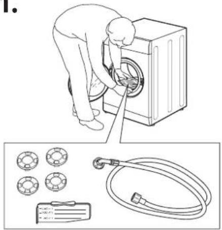
natural_image
Illustration of a person washing a washing machine with a hose and two circular components below (no text or symbols)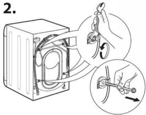
4.5.
natural_image
Line drawing of a refrigerator interior with hands adjusting the switch (no text or symbols)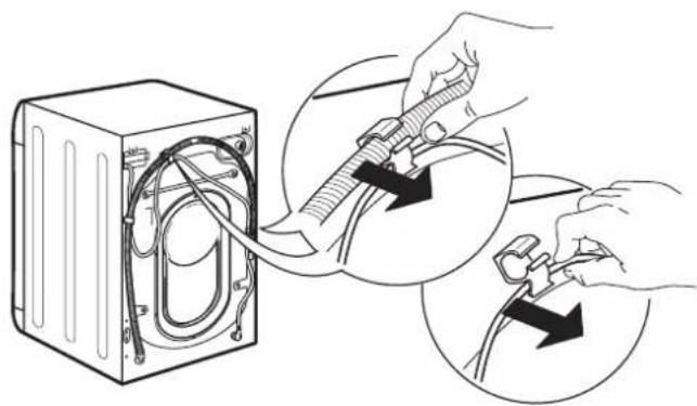
natural_image
Illustration of hands connecting a device into a housing with cable routing (no text or symbols)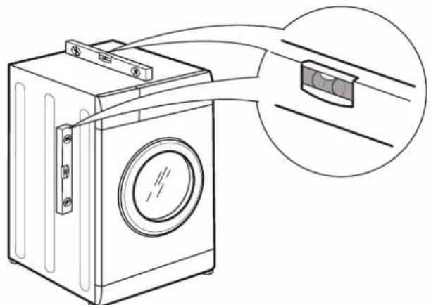
natural_image
Line drawing of a washing machine with attached circuit board and cable connector (no text or symbols)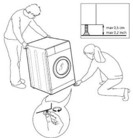
9.8.
10.11.
natural_image
Pure electrical circuit lines without any symbolsFig. 1
natural_image
Technical drawing of a mechanical flange component with bolt holes (no text or symbols)natural_image
Simple line drawing of a rectangular component with two circular holes, labeled 'aimant' at the bottom (no other text or symbols)Fig. 3 Fig. 4
natural_image
Simple line drawing of a three-hole electrical contactor (no text or symbols on the diagram itself)Fig. 4/B
| Type A B | C D | |||
| Longueur 1 | 3 mm 25 mm | 20 mm 7 mm |
natural_image
Diagram of a mechanical component with directional arrows indicating movement or force (no text or symbols)Fig. 8 Fig. 9
natural_image
Simple line drawing of a rectangular box with a handle and lid, no text or symbols present.A
natural_image
Line drawing of a washing machine with lid and side panel, showing internal components and airflow direction (no text or symbols)B
natural_image
Line drawing of a washing machine with side panels and control buttons (no text or symbols)C
natural_image
Diagram of a door switch with a door removed, showing internal components and directional arrows (no text or symbols)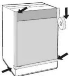
natural_image
Diagram of a rectangular box with a circular button and directional arrows indicating movement or force (no text or symbols)E
natural_image
Technical drawing of a mechanical flange component with bolt holes (no text or symbols)Σχ.3 Σχ.4
natural_image
Simple line drawing of an oval object with three circular holes, labeled 'No 4 Apostáteç' below (no other text or symbols)Σχ. 4/B
natural_image
Diagram of a mechanical or electrical component with directional arrows indicating movement (no text or symbols)Σχ.8 Σχ.9
natural_image
Simple line drawing of a rectangular box with a lid and handle, no text or symbols present.A
natural_image
Line drawing of a box with a circular vent and an open lid, showing a rotation arrow (no text or symbols)B
natural_image
Line drawing of a washing machine with side panels and control buttons (no text or symbols)C
natural_image
Diagram of a door switch with internal components and directional arrows, labeled D (no text or symbols)
natural_image
Diagram of a rectangular appliance with a lid and side-mounted scroll, showing directional arrows (no text or symbols)E
Аксесоари за монтаж на врати (фиг. 1-2-3-4-5).
natural_image
Technical drawing of a mechanical flange component with bolt holes (no text or symbols)natural_image
Technical drawing of a mechanical component with rounded corners and a square slot (no text or symbols)Фиг. 3 Фиг. 4
Фиг. 5
Фиг. 4/В
natural_image
Pure technical diagram showing a mechanical component with directional arrows indicating motion or force (no text or symbols)Fig. 8 Fig. 9
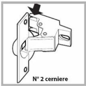
Fig. 2
natural_image
Technical drawing of a mechanical flange component with bolt holes and concentric circles (no text or symbols)Riscontro magnete
natural_image
Simple line drawing of a rectangular component with two circular ends and a central square, labeled 'ontro magnete' below (no other text or symbols)Fig. 4
natural_image
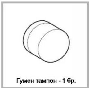
Simple line drawing of a cylindrical object labeled 'N° 1 Tassello in gomma' (no other text or symbols)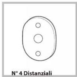
natural_image
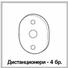
Simple line drawing of a circular object with three holes, labeled 'N° 4 Distanziali' below (no other text or symbols)Fig. 4/B
natural_image
Pure technical diagram showing a mechanical component with directional arrows, no text or symbols presentFig. 8 Fig. 9
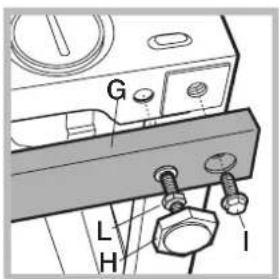
Fig. 11 Fig. 12
Before using the appliance, read these safety instructions. Keep them nearby for future reference. These instructions and the appliance itself provide important safety warnings, to be observed at all times. The manufacturer declines any liability for failure to observe these safety instructions, for inappropriate use of the appliance or incorrect setting of controls.
⚠️ Very young children (0-3 years) should be kept away from the appliance. Young children (3-8 years) should be kept away from the appliance unless continuously supervised. Children from 8 years old and above and persons with reduced physical, sensory or mental capabilities or lack of experience and knowledge can use this appliance only if they are supervised or have been given instructions on safe use and understand the hazards involved. Children must not play with the appliance. Cleaning and user maintenance must not be carried out by children without supervision. Never open the door forcibly or use it as a step.
PERMITTED USE
⚠️ CAUTION: The appliance is not intended to be operated by means of an external switching device, such as a timer, or separate remote controlled system.
This appliance is intended to be used in household and similar applications such as: staff kitchen areas in shops, offices and other working environments; farm houses; by clients in hotels, motels, bed & breakfast and other residential environments; areas for communal use in blocks of flats or in launderettes.
Do not load the machine above the maximum capacity (kg of dry cloth) indicated in the programme table.
This appliance is not for professional use. Do not use the appliance outdoors.
Do not use any solvents (e.g. turpentine, benzene), detergents containing solvents, scouring powder, glass or general purpose cleaners, or flammable fluids; do not machine wash fabrics that have been treated with solvents or flammable liquids.
INSTALLATION
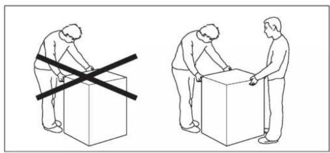
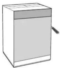
The appliance must be handled and installed by two or more persons - risk of injury. Use protective gloves to unpack and install - risk of cuts.
If you want to stack a dryer on top of your washing machine, first contact our After-Sales Service or your specialist dealer to verify whether this is possible. This is only possible if the dryer is attached to the washing machine by means of appropriate stacking kit available through our After- Sales Service or your specialist dealer.
⚠️ Move the appliance without lifting it by the
worktop or top lid.
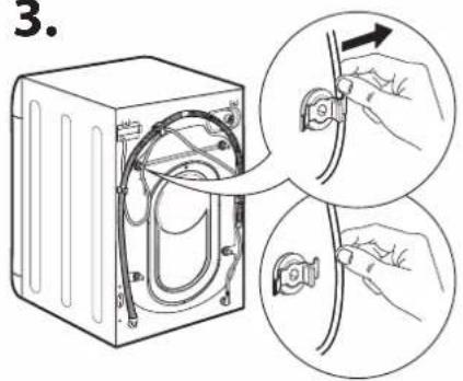
⚠️ Installation, including water supply (if any) and electrical connections and repairs must be carried out by a qualified technician. Do not repair or replace any part of the appliance unless specifically stated in the user manual. Keep children away from the installation site. After unpacking the appliance, make sure that it has not been damaged during transport. In the event of problems, contact the dealer or your nearest After-sales Service. Once installed, packaging waste (plastic, styrofoam parts etc.) must be stored out of reach of children - risk of suffocation. The appliance must be disconnected from the power supply before any installation operation - risk of electric shock. During installation, make sure the appliance does not damage the power cable - risk of fire or electric shock. Only activate the appliance when the installation has been completed.
⚠ Do not install your appliance where it may be exposed to extreme conditions, such as: poor ventilation, temperatures below 5 °C or above 35 °C.
When installing the appliance make sure that the four feet are stable and resting on the floor, adjusting them as required, and check that the appliance is perfectly to level using a spirit level.
⚠️ If the appliance is being installed on wood or "floating" floors (certain parquet and laminate materials), secure a 60 x 60 x 3 cm (at least) sheet of plywood to the floor then place the appliance on top of this.
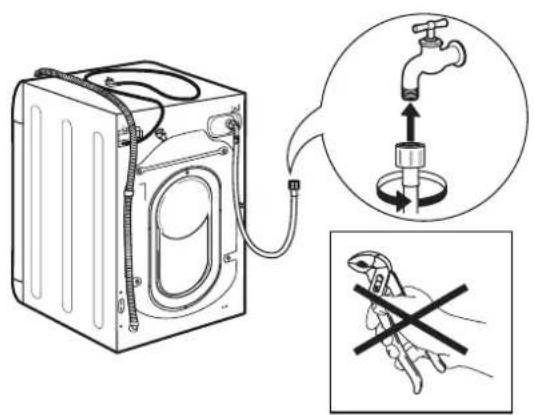
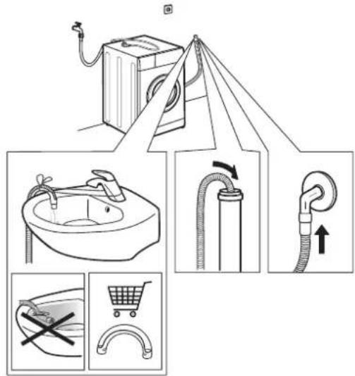
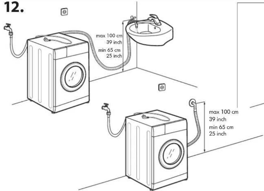
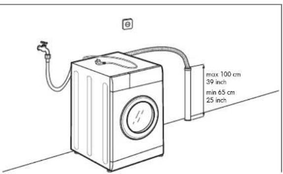
⚠️ Connect the water inlet hose(s) to the water supply in accordance with the regulations of your local water company.
⚠️ For cold fill only models: do not connect to the hot water supply.
⚠ For models with hot fill: the hot water inlet temperature must not exceed 60 °C.
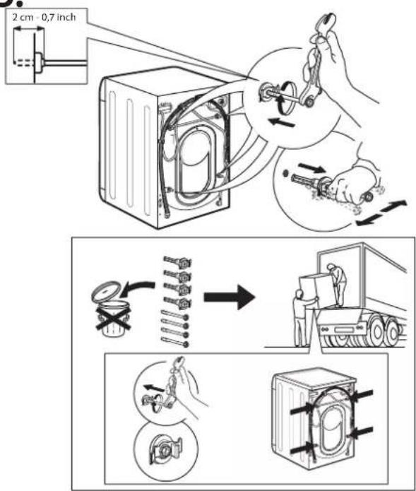
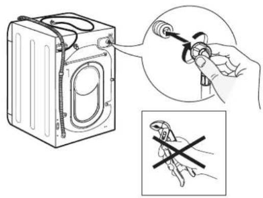
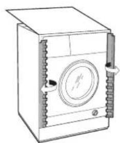
⚠ The washing machine is fitted with transport bolts to prevent any possible damage to the interior during transport. Before using the machine, it is imperative that the transport bolts are removed. After their removal, cover the openings with the 4 enclosed plastic caps.
⚠️ After installation of the device, wait a few hours before starting it so that it acclimates to the environmental conditions of the room.
⚠ Make sure that the ventilation openings in the base of your washing machine (if available on your model) are not obstructed by a carpet or other material.
⚠️ Use only new hoses to connect the appliance to the water supply. The old hose-sets should not be reused.
⚠️ The supply water pressure must be in the 0.1-1 MPa range.
⚠ Do not repair or replace any part of the appliance unless specifically stated in the user manual. Use only authorized After-sales Service. Self or non-professional repair may lead to dangerous incident resulting in live or health threatening and/or significant property damage.
The spare parts for the household machine will be available for 10 years after placing the last unit on the market as dictated by the European Ecodesign regulation.
ELECTRICAL WARNINGS
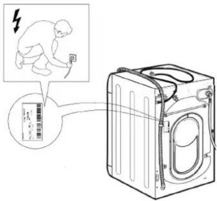
It must be possible to disconnect the appliance from the power supply by unplugging it if plug is accessible, or by a multi-pole switch installed upstream of the socket in accordance with the wiring rules and the appliance must be earthed in conformity with national electrical safety standards.
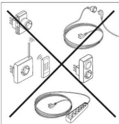
Do not use extension leads, multiple sockets or adapters. The electrical components must not be accessible to the user after installation. Do not use the appliance when you are wet or barefoot. Do not operate this appliance if it has a damaged power cable or plug, if it is not working properly, or if it has been damaged or dropped.
⚠️ If the supply cord is damaged, it must be replaced with an identical one by the manufacturer, its service agent or similarly qualified persons in order to avoid a hazard - risk of electric shock. CLEANING AND MAINTENANCE
⚠ WARNING: Ensure that the appliance is switched off and disconnected from the power supply before performing any maintenance operation. To avoid risk of personal injury use protective gloves
(risk of laceration) and safety shoes (risk of contusion); be sure to handle by two persons (reduce load); never use steam cleaning equipment (risk of electric shock). Non-professional repairs not authorized by the manufacturer could result in a risk to health and safety, for which the manufacturer cannot be held liable. Any defect or damage caused from non-professional repairs or maintenance will not be covered by the guarantee, the terms of which are outlined in the document delivered with the unit.
DISPOSAL OF PACKAGING MATERIALS
The packaging material is 100% recyclable and is marked with the recycle symbol
The various parts of the packaging must therefore be disposed of responsibly and in full compliance with local authority regulations governing waste disposal.
DISPOSAL OF HOUSEHOLD APPLIANCES
This appliance is manufactured with recyclable or reusable materials. Dispose of it in accordance with local waste disposal regulations. For further information on the treatment, recovery and recycling of household electrical appliances, contact your local authority, the collection service for household waste or the store where you purchased the appliance. This appliance is marked in compliance with European Directive 2012/19/EU, Waste Electrical and Electronic Equipment (WEEE). By ensuring this product is disposed of correctly, you will help prevent negative consequences for the environment and human health.
The symbol 📄 on the product or on the accompanying documentation indicates that it should not be treated as domestic waste but must be taken to an appropriate collection center for the recycling of electrical and electronic equipment.
INSTRUCTIONS FOR THE FITTER
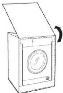
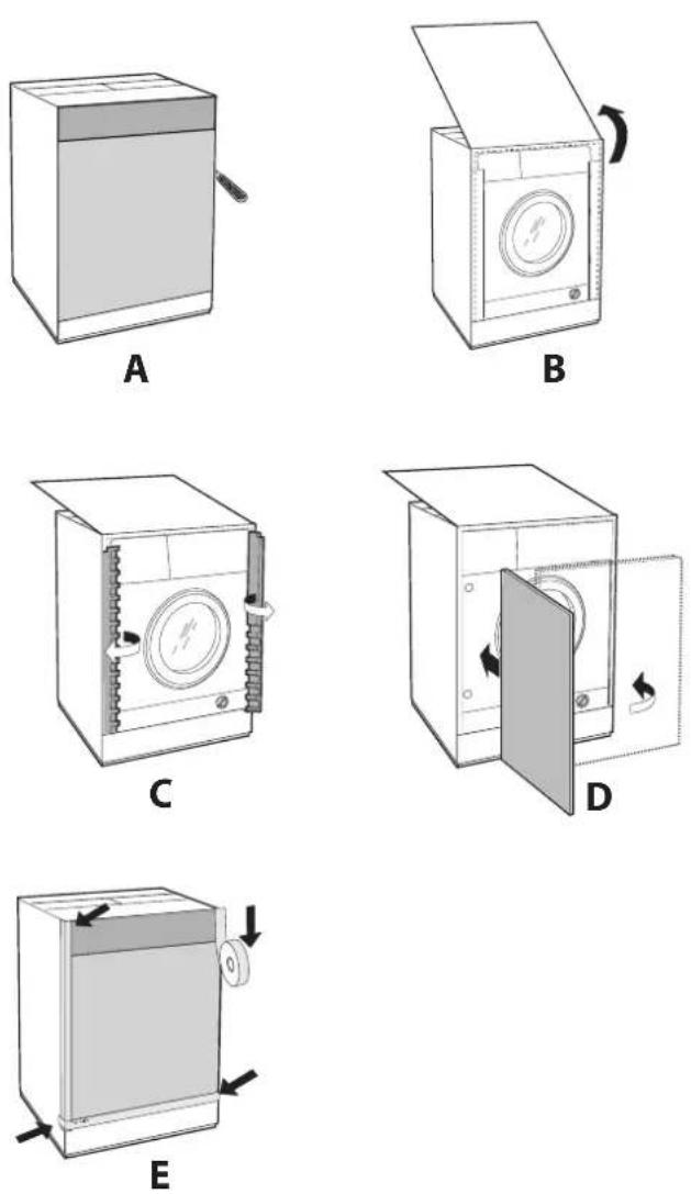
Mounting the wooden panel onto the door and inserting the machine into cabinets:
In the case where the machine must be shipped for final installation after the wooden panel has been mounted, we suggest leaving it in its original packaging. The packaging was designed to make it possible to mount the wooden panel onto the machine without removing it completely (see figures below).
The wooden panel that covers the face of the machine must not be less than 13 mm in thickness and can be hinged on either the right or left. For the sake of practicality when using the machine, we recommend that the panel be hinged on the same side as the door for the machine itself - the left.
Door Mounting Accessories (Fig. 1-2-3-4-5).
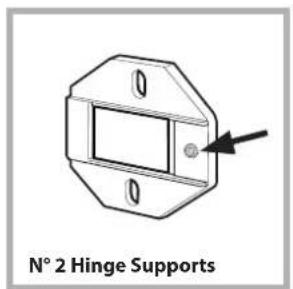
Fig. 1

Fig. 2
natural_image
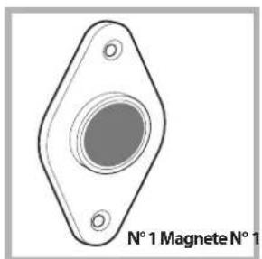
Technical drawing of a mechanical flange component with bolt holes (no text or symbols)Magnet plate
natural_image
Simple line drawing of a rectangular component with two circular holes, labeled 't plate' at the bottom (no other text or symbols)Fig. 3 Fig. 4
natural_image
Simple line drawing of a rubber plug (no text or symbols on the diagram itself)Fig. 5
natural_image
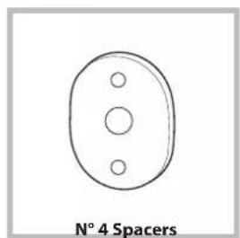
Simple line drawing of a circular object with three holes, labeled 'N° 4 Spacers' below (no other text or symbols)Fig. 4/B
| Type A B C D | ||||
| Lenght 13 mm 25 mm 20 mm 7 mm | ||||
- No. 6 type A self-threading screws, l=13 mm.
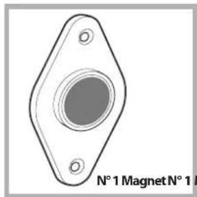
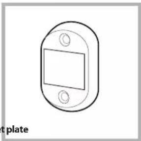
- No. 2 type B metric, countersunk screws, I = 25; for fastening the magnet plate to the cabinet.
- No. 4 type C metric screws, l=20 mm; for mounting the hinge supports to the cabinet.
- No. 4 type D metric screws, l = 7 mm; for mounting the hinges on the supports.
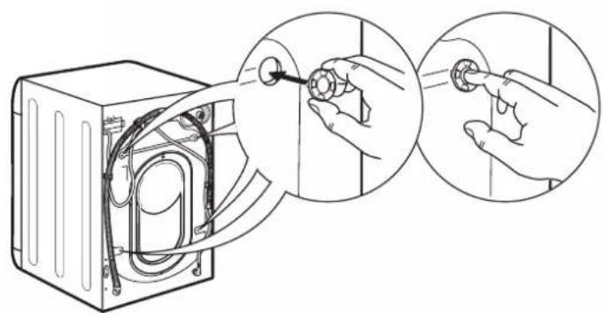
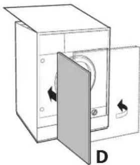
Mounting the Parts onto the Face of the Machine.
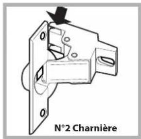
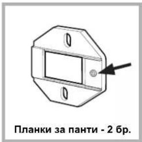
- Separate hinge supports from the hinges by removing the screws type D.
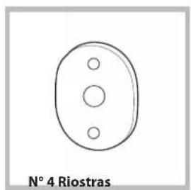
- Fit the hinge supports to the appliance front panel, positioning the hole marked with an arrow in fig. 1 so that it is on the inner side of the front panel. Fit a spacer (fig. 4/B) between the surfaces using type C screws.
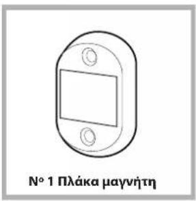
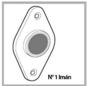
- Fit the magnet plate at the top of the opposite side, using type B screws to fix two spacers (fig. 4/B) between the plate and the surface.
Using the Drilling Template.
- To trace the positions of the holes on the left-hand side of the panel, align the drilling template to the top left side of the panel using the lines traced on the extremities as a reference.
- To trace the positions of the holes on the right-hand side of the panel, align the drilling template to the top right side of the panel.
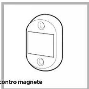
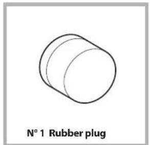
- Use an appropriately sized router to mill the holes for the two hinges, the rubber plug and the magnet.
Mounding the Parts onto the Wooden Panel (Door).
- Insert the hinges into the holes (the movable part of the hinge must be positioned facing away from the panel) and fasten them with the 4 type A screws.
- Insert the magnet into the top hole on the opposite side of the hinges and fasten it with the two type B screws.
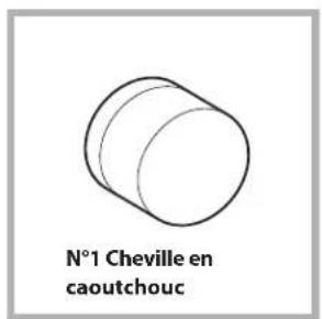
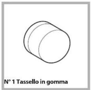
- Insert the rubber plug into the bottom hole. The panel is now ready to be mounted onto the machine.
Mounting the Panel into the machine.
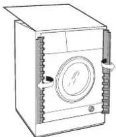
Insert the nib of the hinge (indicated by the arrow in fig. 2) into the hole for the hinge and push the panel towards the front of the machine. Fasten the two hinges with the type D screws.
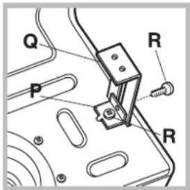
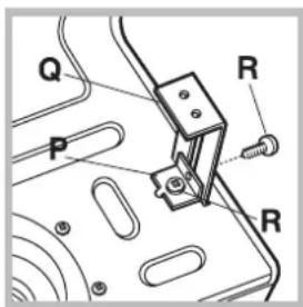
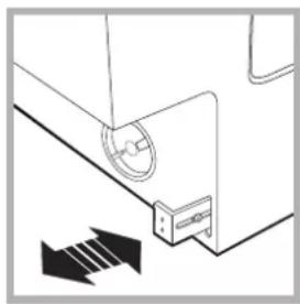
Fastening the plinth guide.
If the machine is installed at the end of a set of modular cabinets, mount either one or both of the guides for the base molding (as shown in fig. 8). Adjust them for depth based on the position of the base molding, and, if necessary, fasten the base to the guides (fig. 9).
This is how to assemble the plinth guide (fig. 8): Fasten angle P using screw R, insert plinth guide Q into the special slot and once it is in the desired position, lock it in place using angle P and screw R.
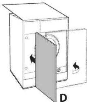
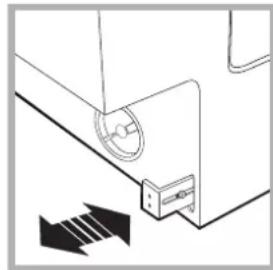
Inserting the machine into the Cabinet.
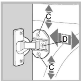
- Push the machine into the opening, aligning it with the cabinets (fig. 6).
- Regulate the adjustable feet to raise the machine to the appropriate height.
- To adjust the position of the wooden panel in both the vertical and horizontal directions, use the C and D screws, as shown in fig. 7.
Important: close the lower part of the appliance front and sides in case machine is installed at the end of set of modular cabinets, by ensuring that the plinth rests against the floor.
Fig. 6 Fig. 7
natural_image
Pure diagram of a mechanical component with directional arrows indicating motion (no text or symbols)Fig. 8 Fig. 9
Accessories provided for the height adjustment.
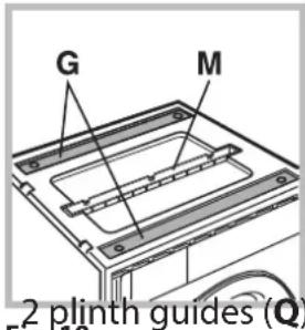
The following can be found inside the polystyrene lid (fig. 10): 2 crossbars (G), 1 strip (M) the following can be found inside the appliance drum: 4 additional feet (H), 4 screws (I), 4 screws (R), 4 nuts (L),
Fig. 10
Adjusting the appliance height.
The height of the appliance can be adjusted (from 815 mm to 835 mm), by turning the 4 feet.
Should you require the appliance to be placed higher than the above height, you need to use the following accessories to raise it to up to 870 mm:
the two crossbars (G); the 4 feet (H); the 4 screws (I); the 4 nuts (L) then perform the following operations (fig. 11):
Lay down machine to back side, make sure, to do not damage drain hose and power supply cable. remove the 4 original feet, place a crossbar G at the front of the appliance, fastening it in place using screws I (screwing them in where the original feet were) then insert the new feet H.
Repeat the same operation at the back of the appliance.
Now adjust feet H to raise or lower the appliance from 835 mm to 870 mm.
Once you have reached the desired height, lock nuts L onto crossbar G.
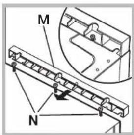
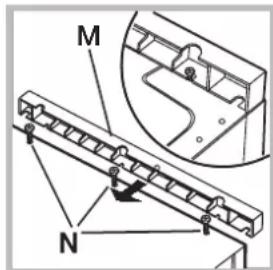
To adjust the appliance to a height between 870 mm and 900 mm, you need to mount strip M, adjusting feet H to the required height.
Insert the strip as follows:
loosen the three screws N situated at the front of the Top cover of the appliance, insert strip M as shown in fig. 12, then fasten screws N.
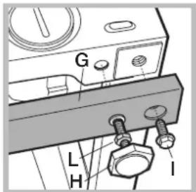
Fig. 11 Fig. 12
natural_image
Technical drawing of a mechanical component with an arrow pointing to a rectangular cutout (no text or symbols on the part itself)Fig. 1
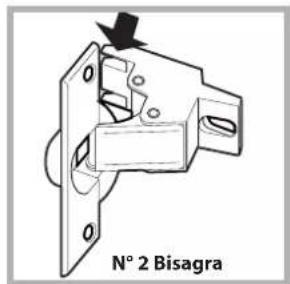
Fig. 2
natural_image
Technical drawing of a mechanical flange component with mounting holes and central bore (no text or symbols)Fig. 3 Fig. 4
natural_image
Simple line drawing of a 3D cylinder labeled 'N° 1 Taco de goma' (no other text or symbols)Fig. 5
natural_image
Simple line drawing of a circular object with three holes, labeled 'N° 4 Riostras' below (no other text or symbols)Fig. 4/B
| Tipo A B | C D | |||
| Longitud | 13 mm 25 mm | 20 mm 7 mm |
natural_image
Simple line drawing of a rectangular box with a handle and lid, no text or symbols present.A

natural_image
Line drawing of a front-loading washing machine with a circular vent and lid (no text or symbols)B
natural_image
Line drawing of a washing machine with side panels and control buttons (no text or symbols)C

natural_image
Diagram of a cabinet with an open door and internal components, labeled D (no text or symbols)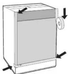
natural_image
Diagram of a rectangular box with a side panel and directional arrows indicating movement or force (no text or symbols)E
natural_image
Diagram of a ceiling-mounted device with a circular component and directional arrows indicating motion (no text or symbols)Fig. 8 Fig. 9