
Palisade (2020) - Automotive HYUNDAI - Free user manual and instructions
Find the device manual for free Palisade (2020) HYUNDAI in PDF.


| Product Type | Automobile |
| Make | Hyundai |
| Model | Palisade |
| Year | 2020 |
| Engine | 3.8L V6 GDI |
| Fuel Type | Unleaded gasoline (87 octane or higher) |
| Transmission | 8-speed automatic |
| Drivetrain | Front-wheel drive or All-wheel drive |
| Seating Capacity | 7 or 8 passengers |
| Dimensions (L x W x H) | 196.1 in x 77.8 in x 68.9 in |
| Wheelbase | 114.2 in |
| Curb Weight | Approximately 4,300 - 4,600 lbs |
| Fuel Tank Capacity | 18.8 gallons |
| Tire Size | 245/60R18 or 245/50R20 |
| Key Safety Features | Airbags (front, side, curtain), pre-tensioner seat belts, ABS, ESC, TPMS, rearview camera, parking sensors, blind-spot collision warning, lane keeping assist, forward collision-avoidance assist |
| Maintenance Interval | Every 7,500 miles or 12 months, whichever comes first |
| Special Features | Smart cruise control, sunroof, power liftgate, heated/ventilated seats, wireless phone charging, 8-inch or 10.25-inch infotainment |
Frequently Asked Questions - Palisade (2020) HYUNDAI
User questions about Palisade (2020) HYUNDAI
0 question about this device. Answer the ones you know or ask your own.
Ask a new question about this device
Download the instructions for your Automotive in PDF format for free! Find your manual Palisade (2020) - HYUNDAI and take your electronic device back in hand. On this page are published all the documents necessary for the use of your device. Palisade (2020) by HYUNDAI.
USER MANUAL Palisade (2020) HYUNDAI
All information in this Owner's Manual is current at the time of publication. However, HYUNDAI reserves the right to make changes at any time so that our policy of continual product improvement may be carried out.
This manual applies to all HYUNDAI models and includes descriptions and explanations of optional as well as standard equipment. As a result, you may find material in this manual that does not apply to your specific vehicle.
CAUTION: MODIFICATIONS TO YOUR HYUNDAI
Your HYUNDAI should not be modified in any way. Such modifications may adversely affect the performance, safety or durability of your HYUNDAI and may, in addition, violate conditions of the limited warranties covering the vehicle. Certain modifications may also be in violation of regulations established by the U.S. Department of Transportation and other federal or state agencies.
TWO-WAY RADIO OR CELLULAR TELEPHONE INSTALLATION
Your vehicle is equipped with electronic fuel injection and other electronic components. It is possible for an improperly installed/adjusted two-way radio or cellular telephone to adversely affect electronic systems. For this reason, we recommend that you carefully follow the radio manufacturer's instructions or consult your HYUNDAI dealer for precautionary measures or special instructions if you choose to install one of these devices.
SAFETY AND VEHICLE DAMAGE WARNING
This manual includes information titled as DANGER, WARNING, CAUTION and NOTICE.
These titles indicate the following:

DANGER
DANGER indicates a hazardous situation which, if not avoided, will result in death or serious injury.

WARNING
WARNING indicates a hazardous situation which, if not avoided, could result in death or serious injury.

CAUTION
CAUTION indicates a hazardous situation which, if not avoided, could result in minor or moderate injury.
NOTICE
NOTICE indicates a situation which, if not avoided, could result in vehicle damage.
HYUNDAI VEHICLE OWNER PRIVACY POLICY
Your Hyundai vehicle may be equipped with technologies and services that use information collected, generated, recorded or stored by the vehicle. Hyundai has created a Vehicle Owner Privacy Policy to explain how these technologies and services collect use and share this information.
You may read our Vehicle Owner Privacy Policy on the Hyundaiusa.com website at: https://www.hyundaiusa.com/owner-privacy-policy.aspx
If you would like to receive a hard copy of our Vehicle Owner Privacy Policy, please contact our Customer Connect Center at:
Hyundai Customer Care
P.O. Box 20850
Fountain Valley, CA 92728
800-633-5151
consumeraffairs@hmausa.com
Hyundai's Customer Connect Center representatives are available Monday through Friday, between the hours of 5:00 AM and 7:00 PM PST and Saturday and Sunday between 6:30 AM and 3:00 PM PST (English).
For Customer Connect Center assistance in Spanish or Korean, representatives are available Monday through Friday between 6:30 AM and 3:00 PM PST.
INTRODUCTION
Congratulations, and thank you for choosing HYUNDAI. We are pleased to welcome you to the growing number of discerning people who drive HYUNDAIs. We are very proud of the advanced engineering and high-quality construction of each HYUNDAI we build.
Your Owner's Manual will introduce you to the features and operation of your new HYUNDAI. To become familiar with your new HYUNDAI, so that you can fully enjoy it, read this Owner's Manual carefully before driving your new vehicle.
This manual contains important safety information and instructions intended to familiarize you with your vehicle's controls and safety features so you can safely operate your vehicle.
This manual also contains information on maintenance designed to enhance safe operation of the vehicle. It is recommended that all service and maintenance on your car be performed by an authorized HYUNDAI dealer. HYUNDAI dealers are prepared to provide high-quality service, maintenance and any other assistance that may be required.
This Owner's Manual should be considered a permanent part of your vehicle, and should be kept in the vehicle so you can refer to it at any time. The manual should stay with the vehicle if you sell it to provide the next owner with important operating, safety and maintenance information.
HYUNDAI MOTOR AMERICA
CAUTION
Severe engine and transmission damage may result from the use of poor quality fuels and lubricants that do not meet HYUNDAI specifications. You must always use high quality fuels and lubricants that meet the specifications listed on Page 8-7 in the Vehicle Specifications section of the Owner's Manual.
Copyright 2019 HYUNDAI Motor America. All rights reserved. No part of this publication may be reproduced, stored in any retrieval system or transmitted in any form or by any means without the prior written permission of HYUNDAI Motor America.
GUIDE TO HYUNDAI GENUINE PARTS
1. What are HYUNDAI Genuine Parts?
HYUNDAI Genuine Parts are the same parts used by HYUNDAI Motor Company to manufacture vehicles. They are designed and tested for the optimum safety, performance, and reliability for our customers.

Genuine Parts
2. Why should you use genuine parts?
HYUNDAI Genuine Parts are engineered and built to meet rigid manufacturing requirements. Damage caused by using imitation, counterfeit or used salvage parts is not covered under the HYUNDAI New Vehicle Limited Warranty or any other HYUNDAI warranty.
In addition, any damage to or failure of HYUNDAI Genuine Parts caused by the installation or failure of an imitation, counterfeit or used salvage part is not covered by any HYUNDAI Warranty.
3. How can you tell if you are purchasing HYUNDAI Genuine Parts?
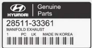
Look for the HYUNDAI Genuine Parts Logo on the package (see below).
HYUNDAI Genuine Parts exported to the U.S. are packaged with labels written only in English.
HYUNDAI Genuine Parts are only sold through authorized HYUNDAI Dealerships.
natural_image
Stacked 3D printer illustration showing layered structure (no text or symbols)
HOW TO USE THIS MANUAL
We want to help you get the greatest possible driving pleasure from your vehicle. Your Owner's Manual can assist you in many ways. To gain an overview of the contents of your Owner's Manual, use the Table of Contents in the front of the manual. The first page of each Chapter includes a detailed Table of Contents of the topics in that Chapter.
To quickly locate information about your vehicle, use the Index in the back of the manual. It is an alphabetical list of what is in this manual and the page number where it can be found.
For your convenience, we have incorporated tabs on the right-hand page edges. These tabs are coded with the Chapter titles to assist you with navigating through the manual.
SAFETY MESSAGES
Your safety, and the safety of others, is very important. This Owner's Manual provides you with many safety precautions and operating procedures. This information alerts you to potential hazards that may hurt you or others, as well as damage to your vehicle.
Safety messages found on vehicle labels and in this manual describe these hazards and what to do to avoid or reduce the risks.
Warnings and instructions contained in this manual are for your safety. Failure to follow safety warnings and instructions can lead to serious injury or death.
Throughout this manual DANGER, WARNING, CAUTION, NOTICE and the SAFETY ALERT SYMBOL will be used.

This is the safety alert symbol. It is used to alert you to potential physical injury hazards. Obey all safety messages that follow this symbol to avoid possible injury or death. The safety alert symbol precedes the signal words DANGER, WARNING and CAUTION.
DANGER
DANGER indicates a hazardous situation which, if not avoided, will result in death or serious injury.
WARNING
WARNING indicates a hazardous situation which, if not avoided, could result in death or serious injury.

CAUTION
CAUTION indicates a hazardous situation which, if not avoided, could result in minor or moderate injury.
NOTICE
NOTICE indicates a situation which, if not avoided, could result in vehicle damage.
FUEL REQUIREMENTS
Your new vehicle is designed to obtain maximum performance with UNLEADED FUEL, as well as minimize exhaust emissions and spark plug fouling.
Your new vehicle is designed to use only unleaded fuel having an octane number ((R+M)/2) of 87 (Research Octane Number 91) or higher. (Do not use methanol blended fuels)
NOTICE
To prevent damage to the engine and engine components, never add any fuel system cleaning agents to the fuel tank other than what has been specified.
Consult an authorized HYUNDAI dealer for additional information.

WARNING
- Do not "top off" after the nozzle automatically shuts off when refueling.
• Always check that the fuel cap is installed securely to prevent fuel spillage in the event of an accident.
Gasoline containing alcohol or methanol
Gasohol, a mixture of gasoline and ethanol (also known as grain alcohol) are being marketed along with or instead of leaded or unleaded gasoline. For example, "E15" is a gasohol comprised of 15% ethanol and 85% gasoline.
Do not use gasohol containing more than 15% ethanol, and do not use gasoline or gasohol containing any methanol. Either of these fuels may cause drivability problems and damage to the fuel system, engine control system and emission control system.
Discontinue using gasohol of any kind if drivability problems occur.
"E85" fuel is an alternative fuel comprised of 85 percent ethanol and 15 percent gasoline, and is manufactured exclusively for use in Flexible Fuel Vehicles. "E85" is not compatible with your vehicle. Use of "E85" may result in poor engine performance and damage to your vehicle's engine and fuel system. HYUNDAI recommends that customers do not use fuel with an ethanol content exceeding 15 percent.
NOTICE
To prevent damage to your vehicle's engine and fuel system:
- Never use gasohol which contains methanol.
- Never use gasohol containing more than 15% ethanol.
- Never use leaded fuel or leaded gasohol.
- Never use "E85" fuel.
Your New Vehicle Limited Warranty does not cover damage to the fuel system or any performance problems caused by the use of "E85" fuel.
Using Fuel Additives (except Detergent Fuel Additives)
Using fuel additives such as:
- Silicone fuel additive
- Ferrocene (iron-based) fuel additive
- Other metallic-based fuel additives may result in cylinder misfire, poor acceleration, engine stalling, damage to the catalyst, or abnormal corrosion, and may cause damage to the engine resulting in a reduction in the overall life of the powertrain.
- The Malfunction Indicator Lamp (MIL) may illuminate.
NOTICE
Damage to the fuel system or performance problem caused by the use of these fuels or fuel additives may not be covered by your New Vehicle Limited Warranty.
Gasoline containing MMT
Some gasoline contains harmful manganese-based fuel additives such as MMT (Methylcyclopentadienyl Manganese Tricarbonyl).
HYUNDAI does not recommend the use of gasoline containing MMT.
This type of fuel can reduce vehicle performance and affect your emission control system.
The malfunction indicator lamp on the cluster may come on.
Detergent Fuel Additives
HYUNDAI recommends that you use good quality gasolines treated with detergent additives such as TOP TIER Detergent Gasoline, which help prevent deposit formation in the engine. These gasolines will help the engine run cleaner and enhance performance of the Emission Control System. For more information on TOP TIER Detergent Gasoline, please go to the website (www.toptiergas.com).
VEHICLE MODIFICATIONS
For customers who do not use TOP Tier Detergent Gasoline regularly, and have problems starting or the engine does not run smoothly, detergent-based fuel additives that you can purchase separately may be added to the gasoline. If TOP TIER Detergent Gasoline is not available, one bottle of additive added to the fuel tank according to the maintenance schedule is recommended (refer to the Maintenance Schedule in chapter 7).
Additives are available from your authorized HYUNDAI dealer along with information on how to use them. Do not mix other additives.
Operation in foreign countries
If you are going to drive your vehicle in another country, be sure to:
- Observe all regulations regarding registration and insurance.
-
Determine that acceptable fuel is available.
-
This vehicle should not be modified. Modification of your vehicle could affect its performance, safety or durability and may even violate governmental safety and emissions regulations.
In addition, damage or performance problems resulting from any modification may not be covered under warranty. - If you use unauthorized electronic devices, it may cause the vehicle to operate abnormally, wire damage, battery discharge and fire. For your safety, do not use unauthorized electronic devices.
VEHICLE BREAK-IN PROCESS
By following a few simple precautions for the first 600 miles (1,000 km) you may add to the performance, economy and life of your vehicle.
- Do not race the engine.
- While driving, keep your engine speed (rpm, or revolutions per minute) between 2,000 rpm and 4,000 rpm.
- Do not maintain a single speed for long periods of time, either fast or slow. Varying engine speed is needed to properly break-in the engine.
- Avoid hard stops, except in emergencies, to allow the brakes to seat properly.
WARNING
CALIFORNIA PROPOSITION 65 WARNING
Items contained in motor vehicles or emitted from them are known to the State of California to cause cancer and birth defects or reproductive harm. These include:
• Gasoline and its vapors
- Engine exhaust
• Used engine oil
- Interior passenger compartment components and materials
- Component parts which are subject to heat and wear
In addition, battery posts, terminals and related accessories contain lead, lead compounds and other chemicals known to the State of California to cause cancer and reproductive harm.
For more information go to https://www.p65warnings.ca.gov/passenger-vehicle
VEHICLE DATA COLLECTION AND EVENT DATA RECORDERS
This vehicle is equipped with an event data recorder (EDR). The main purpose of an EDR is to record, in certain crash or near crash-like situations, such as an air bag deployment or hitting a road obstacle, data that will assist in understanding how a vehicle's systems performed. The EDR is designed to record data related to vehicle dynamics and safety systems for a short period of time, typically 30 seconds or less. The EDR in this vehicle is designed to record such data as:
• How various systems in your vehicle were operating;
- Whether or not the driver and passenger safety belts were buckled/fastened;
- How far (if at all) the driver was depressing the accelerator and/or brake pedal; and,
- How fast the vehicle was traveling.
These data can help provide a better understanding of the circumstances in which crashes and injuries occur. NOTE: EDR data are recorded by your vehicle only if a non-trivial crash situation occurs; no data are recorded by the EDR under normal driving conditions and no personal data (e.g., name, gender, age, and crash location) are recorded. However, other parties, such as law enforcement, could combine the EDR data with the type of personally identifying data routinely acquired during a crash investigation.
To read data recorded by an EDR, special equipment is required, and access to the vehicle or the EDR is needed. In addition to the vehicle manufacturer, other parties, such as law enforcement, that have the special equipment, can read the information if they have access to the vehicle or the EDR.
TABLE OF CONTENTS
| Your Vehicle at a Glance | 1 |
| Safety System of Your Vehicle | 2 |
| Convenient Features of Your Vehicle | 3 |
| Multimedia System | 4 |
| Driving Your Vehicle | 5 |
| What to Do in an Emergency | 6 |
| Maintenance | 7 |
| Specifications, Consumer Information and Reporting Safety Defects | 8 |
| Index | 1 |
Your vehicle at a glance
Exterior Overview....1-2
Interior Overview 1-4
Instrument Panel Overview 1-5
Engine Compartment 1-6
EXTERIOR OVERVIEW
Front view
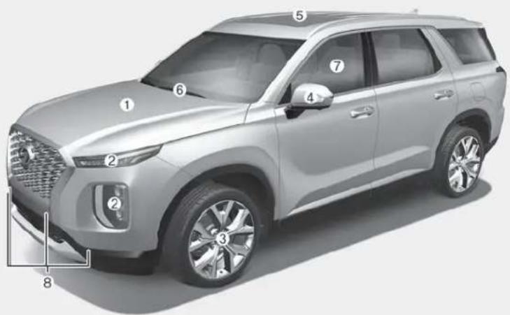
The actual shape may differ from the illustration.
- Hood....3-53
- Front lamps 3-132, 7-61
- Tires and wheels....7-33, 8-5
- Side view mirror 3-39
-
Sunroof....3-46
-
Wiper blade 7-27
- Windows....3-42
- Parking Distance Warning system (Reverse/Forward) 3-155
OLX2019001N
■Rear view
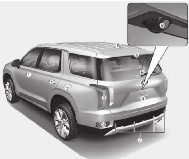
The actual shape may differ from the illustration.
- Door 3-15
- Fuel filler door 3-66
- Rear lamps....7-64
- Liftgate 3-54
-
High mounted stop lamp 7-66
-
Wiper blade 7-28
- Parking Distance Warning system (Reverse) 3-152
- Antenna 4-2
- Rearview monitor 3-148
OLX2018002L
INTERIOR OVERVIEW
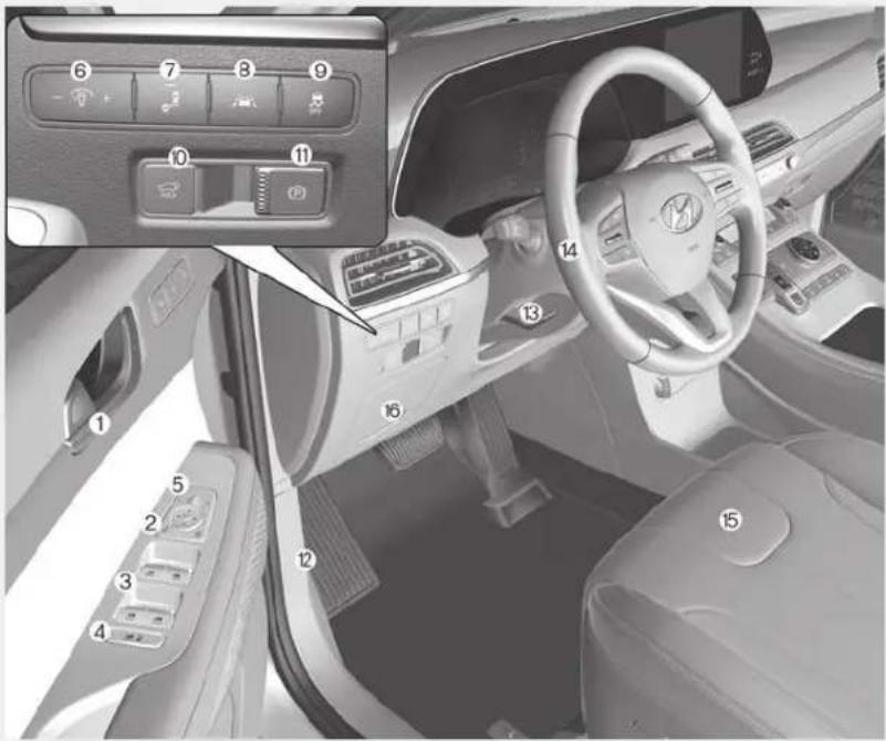
The actual shape may differ from the illustration.
- Inside door handle ....3-16
- Central door lock/unlock switch ....3-17
- Power window switches .....3-43
- Power window lock button/....3-45 Electronic child safety lock button.....3-20
- Side view mirror control switch .....3-40
- Instrument panel illumination control switch 3-71
- Blind-spot Collision Warning (BCW) system 5-78
- Lane Keeping assist (LKA) system....5-109
- ESC OFF button 5-35
- Power liftgate button 3-56
- EPB(Electronic Parking Brake)......5-24
- Hood release lever 3-53
- Steering wheel tilt/telescopic lever .....3-31
- Steering wheel 3-31
- Seat....2-4
- Fuse box 7-51
OLX2019003N
INSTRUMENT PANEL OVERVIEW (I)
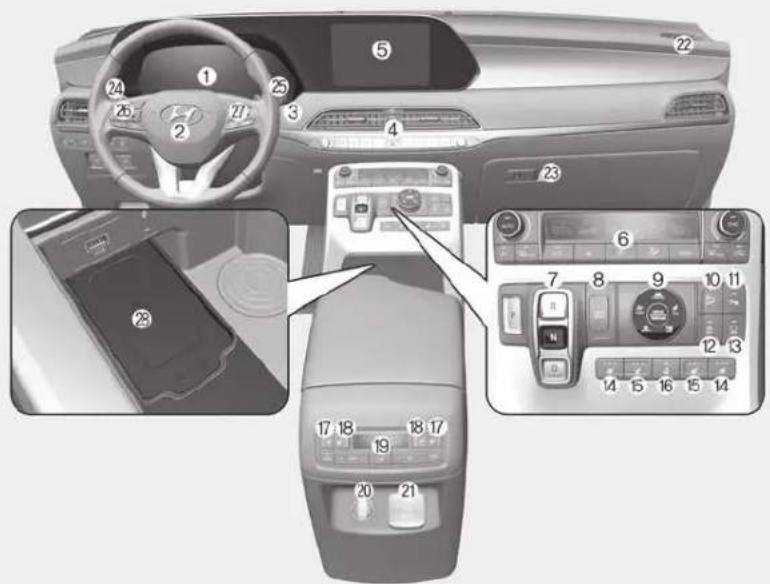
OLX2019004N
The actual shape may differ from the illustration.
-
Instrument cluster....3-69
-
Driver's front air bag....2-59
-
Key ignition switch/....5-7 Engine Start/Stop button ....5-10
-
Hazard warning flasher switch 6-2
-
Audio/Video/Navigation System 4-4
-
Manual climate control system/....3-159 Automatic climate control system.....3-171
-
Automatic transmission shift button .....5-15
-
Auto Hold 5-29
-
Drive mode knob 5-55
-
DBC button....5-39
-
Parking Distance Warning (Reverse/Forward) button....3-156
-
Idle stop and go (ISG) OFF button .....5-51
-
Surround view monitor 3-149
-
Air ventilation seat 2-27
-
Seat warmer....2-26
-
Heated steering wheel 3-32
-
Air ventilation seat (2nd row)....2-27
-
Seat warmer (2nd row) 2-26
-
Climate control system (rear)....3-164
-
Power outlet 3-197
-
AC inverter 3-198
-
Passenger's front air bag 2-59
-
Glove box 3-192
-
Light control/Turn signals 3-132
-
Wiper/Washer....3-144
-
Steering wheel audio controls 4-3
-
Smart cruise controls 5-128
-
Wireless cellular phone charging
system 3-201
ENGINE COMPARTMENT
■ Gasoline 3.8 GDI
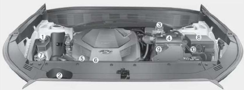
- Engine coolant reservoir....7-18
- Radiator cap 7-19
- Brake fluid reservoir....7-21
- Air cleaner....7-22
- Engine oil filler cap 7-16
- Engine oil dipstick....7-16
- Windshield washer fluid reservoir.....7-22
- Fuse box....7-55
- Battery terminal [+] 7-29
- Battery terminal [-] 7-29
The actual engine compartment in the vehicle may differ from the illustration.
OLX2078002L
Safety system of your vehicle
This chapter provides you with important information about how to protect yourself and your passengers. It explains how to properly use your seats and seat belts, and how your air bags work. Additionally, this chapter explains how to properly restrain infants and children in your vehicle.
Important Safety Precautions....2-2
Always Wear Your Seat Belt 2-2
Restrain All Children....2-2
Air Bag Hazards....2-2
Driver Distraction 2-2
Control Your Speed....2-3
Keep Your Vehicle in Safe Condition....2-3
Seats 2-4
Safety Precautions 2-5
Front Seats 2-6
Rear Seats....2-13
Head Restraints 2-21
Seat Warmers and Air Ventilation Seats......2-26
Seat Belts....2-29
Seat Belt Safety Precautions....2-29
Seat Belt Warning Light 2-30
Seat Belt Restraint System....2-33
Additional Seat Belt Safety Precautions....2-41
Care of Seat Belt....2-44
Child Restraint System (CRS)....2-45
Children Always in the Rear....2-45
Selecting a Child Restraint System (CRS) 2-47
Installing a Child Restraint System (CRS)....2-49
Air Bag - Advanced Supplemental Restraint
System 2-57
Where Are the Air Bags?......2-59
How Does the Air Bag System Operate?......2-63
What to Expect After an Air Bag Inflates....2-67
Occupant Classification System (OCS)....2-68
Why Didn't My Air Bag Go Off in a Collision? .....2-73
SRS Care....2-78
Additional Safety Precautions 2-79
Air Bag Warning Label....2-79
IMPORTANT SAFETY PRECAUTIONS
You will find many safety precautions and recommendations throughout this section, and throughout this manual. The safety precautions in this section are among the most important.
Always Wear Your Seat Belt
A seat belt is your best protection in all types of accidents. Air bags are designed to supplement seat belts, not replace them. So even though your vehicle is equipped with air bags, ALWAYS make sure you and your passengers wear your seat belts, and wear them properly.
Restrain All Children
All children under age 13 should ride in your vehicle properly restrained in a rear seat, not the front seat. Infants and small children should be restrained in an appropriate child restraint. Larger children should use a booster seat with the lap/shoulder belt until they can use the seat belt properly without a booster seat.
Air Bag Hazards
While air bags can save lives, they can also cause serious or fatal injuries to occupants who sit too close to them, or who are not properly restrained. Infants, young children, and shorter adults are at the greatest risk of being injured by an inflating air bag. Follow all instructions and warnings in this manual.
Driver Distraction
Driver distraction presents a serious and potentially deadly danger, especially for inexperienced drivers. Safety should be the first concern when behind the wheel and drivers need to be aware of the wide array of potential distractions, such as drowsiness, reaching for objects, eating, personal grooming, other passengers, and using cellular phones.
Drivers can become distracted when they take their eyes and attention off the road or their hands off the wheel to focus on activities other than driving. To reduce your risk of distraction or getting into an accident:
- ALWAYS set up your mobile devices (i.e., MP3 players, phones, navigation units, etc.) when your vehicle is parked or safely stopped.
- ONLY use your mobile device when allowed by laws and when conditions permit safe use. NEVER text or email while driving. Most states have laws prohibiting drivers from texting. Some states and cities also prohibit drivers from using handheld phones.
- NEVER let the use of a mobile device distract you from driving. You have a responsibility to your passengers and others on the road to always drive safely, with your hands on the wheel as well as your eyes and attention on the road.
Control Your Speed
Excessive speed is a major factor in crash injuries and deaths. Generally, the higher the speed, the greater the risk, but serious injuries can also occur at lower speeds. Never drive faster than is safe for current conditions, regardless of the maximum speed posted.
Keep Your Vehicle in Safe Condition
Having a tire blowout or a mechanical failure can be extremely hazardous. To reduce the possibility of such problems, check your tire pressures and condition frequently, and perform all regularly scheduled maintenance.
SEATS
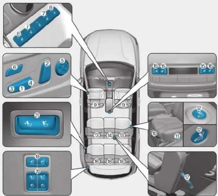
Front seats
(1) Seat sliding forward or rearward
(2) Seatback angle adjustment
(3) Seat cushion angle adjustment
(4) Seat height adjustment
(5) Lumbar support adjustment (Driver's seat)*
(6) Seat cushion length adjustment*
(7) Seat warmer*
(8) Air ventilation seat*
(9) Head restraint
2nd row seat
(10) Seat sliding forward or rearward
(11) Seatback angle adjustment / seat folding
(12) Walk-in switch
(13) Head restraint
(14) Head restraint (8 passengers)
(15) Seat warmer*
(16) Air ventilation seat*
(17) Seat folding strap
3rd row seat
(18) Head restraints
(19) 2nd row seat remote folding switch
(20) 3rd row seat remote folding/ unfolding switch*
(21) Seatback angle adjustment (for 3rd row seat)*
* : if equipped
OLX2039001N
Safety Precautions
Adjusting the seats so that you are sitting in a safe, comfortable position plays an important role in driver and passenger safety together with the seat belts and air bags in an accident.
WARNING
Do not use a cushion that reduces friction between the seat and the passenger. The passenger's hips may slide under the lap portion of the seat belt during an accident or a sudden stop. Serious or fatal internal injuries could result because the seat belt cannot operate properly.
Air bags
You can take steps to reduce the risk of being injured by an inflating air bag. Sitting too close to an air bag greatly increases the risk of injury in the event the air bag inflates.
The National Highway Traffic Safety Administration (NHTSA) recommends that drivers allow at least 10 inches (25 cm) between the center of the steering wheel and their chest.
WARNING
To reduce the risk of serious injury or death from an inflating air bag, take the following precautions:
- Adjust the driver's seat as far to the rear as possible while maintaining the ability to maintain full control of the vehicle.
-
Adjust the front passenger seat as far to the rear as possible.
-
Hold the steering wheel by the rim with hands at the 9 o'clock and 3 o'clock positions to minimize the risk of injuries to your hands and arms.
- NEVER place anything or anyone between the steering wheel and the air bag.
- Do not allow the front passenger to place feet or legs on the dashboard to minimize the risk of leg injuries.
Seat belts
Always fasten your seat belt before starting any trip.
At all times, passengers should sit upright and be properly restrained. Infants and small children must be restrained in appropriate child restraint systems. Adults and children who have outgrown a booster seat must be restrained using the seat belts.
WARNING
Take the following precautions when adjusting your seat belt:
• NEVER use one seat belt for more than one occupant.
• Always position the seatback upright with the lap portion of the seat belt snug and low across the hips.
- NEVER allow children or small infants to ride on a passenger's lap.
- Do not route the seat belt across your neck, across sharp edges, or reroute the shoulder strap away from your body.
- Do not allow the seat belt to become caught or jammed.
Front Seats
WARNING
Take the following precautions when adjusting your seat:
- NEVER attempt to adjust the seat while the vehicle is moving. The seat could respond with unexpected movement and may cause loss of vehicle control resulting in an accident.
- Do not place anything under the front seats. Loose objects in the driver's foot area could interfere with the operation of the foot pedals, causing an accident.
- Do not allow anything to interfere with the normal position and proper locking of the seat-back.
-
Do not place a cigarette lighter on the floor or seat. When you operate the seat, gas may exit out of the lighter causing a fire.
-
Use extreme caution when picking up small objects trapped under the seats or between the seat and the center console. Your hands might be cut or injured by the sharp edges of the seat mechanism.
CAUTION
To prevent injury:
- Do not adjust your seat while wearing your seat belt. Moving the seat cushion forward may cause strong pressure on your abdomen.
- Do not allow your hands or fingers to get caught in the seat mechanisms while the seat is moving.
Manual adjustment (if equipped)
The front seat can be adjusted by using the levers located on the outside of the seat cushion. Before driving, adjust the seat to the proper position so that you can easily control the steering wheel, foot pedals and controls on the instrument panel.
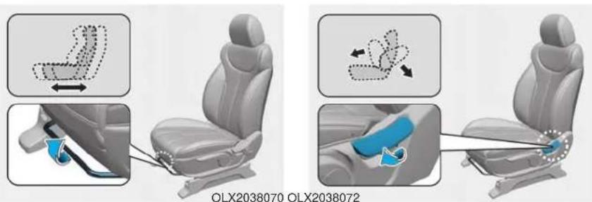
Forward and rearward adjustment
To move the seat forward or rearward:
- Pull up the seat slide adjustment lever and hold it.
- Slide the seat to the position you desire.
- Release the lever and make sure the seat is locked in place. Move forward and rearward without using the lever. If the seat moves, it is not locked properly.
Seatback angle
To recline the seatback:
- Lean forward slightly and lift up the seatback lever.
- Carefully lean back on the seat and adjust the seatback to the position you desire.
- Release the lever and make sure the seatback is locked in place. (The lever MUST return to its original position for the seatback to lock.)
Reclining seatback
Sitting in a reclined position when the vehicle is in motion can be dangerous. Even when buckled up, the protection of your restraint system (seat belts and air bags) is greatly reduced by reclining your seatback.
WARNING
NEVER ride with a reclined seatback when the vehicle is moving.
Riding with a reclined seatback increases your chance of serious or fatal injuries in the event of a collision or sudden stop.
Drivers and passengers should ALWAYS sit well back in their seats, properly belted, and with the seatbacks upright.
Seat belts must be snug against your hips and chest to work properly. When the seatback is reclined, the shoulder belt cannot do its job because it will not be snug against your chest. Instead, it will be in front of you. During an accident, you could be thrown into the seat belt, causing neck or other injuries.
The more the seatback is reclined, the greater chance the passenger's hips will slide under the lap belt or the passenger's neck will strike the shoulder belt.
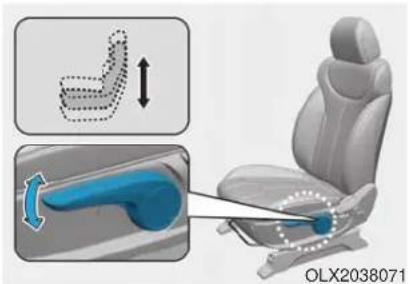
Seat cushion height
To change the height of the seat cushion:
- Push down on the lever several times, to lower the seat cushion.
- Pull up on the lever several times, to raise the seat cushion.
Power adjustment (if equipped)
The front seat can be adjusted by using the control switches located on the outside of the seat cushion. Before driving, adjust the seat to the proper position so that you can easily control the steering wheel, foot pedals and controls on the instrument panel.
WARNING
NEVER allow children in the vehicle unattended. The power seats are operable when the vehicle is turned off.
NOTICE
To prevent damage to the seats:
• Always stop adjusting the seats when the seat has moved as far forward or rearward as possible.
- Do not adjust the seats for longer than necessary when the vehicle is turned off. This may result in unnecessary battery drain.
- Do not operate two or more seats at the same time. This may result in an electrical malfunction.
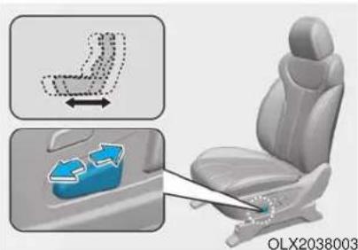
natural_image
Car seat diagram showing side view and side profile with arrows indicating movement (no text or symbols)Forward and rearward adjustment To move the seat forward or rearward:
- Push the control switch forward or rearward.
- Release the switch once the seat reaches the desired position.
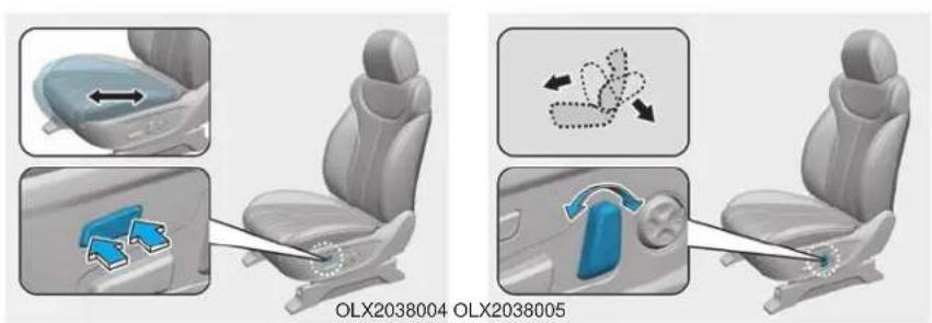
Cushion extension
(for driver's seat, if equipped)
To move the front part of cushion forward:
-
Push the front part of control switch to move the seat cushion to the desired length.
-
Release the switch once the seat cushion reaches the desired length.
To move the front part of cushion rearward:
-
Push the rear part of control switch to move the seat cushion to the desired length.
-
Release the switch once the seat cushion reaches the desired length.
Seatback angle
To adjust the seatback:
- Rotate the top of control switch forward or rearward.
- Release the switch once the seat-back reaches the desired position.
Reclining seatback
Sitting in a reclined position when the vehicle is in motion can be dangerous. Even when buckled up, the protection of your restraint system (seat belts and air bags) is greatly reduced by reclining your seatback.
WARNING
NEVER ride with a reclined seatback when the vehicle is moving.
Riding with a reclined seatback increases your chance of serious or fatal injuries in the event of a collision or sudden stop.
Driver and passengers should ALWAYS sit well back in their seats, properly belted, and with the seatbacks upright.
Seat belts must be snug against your hips and chest to work properly. When the seatback is reclined, the shoulder belt cannot do its job because it will not be snug against your chest. Instead, it will be in front of you. During an accident, you could be thrown into the seat belt, causing neck or other injuries.
The more the seatback is reclined, the greater chance the passenger's hips will slide under the lap belt or the passenger's neck will strike the shoulder belt.
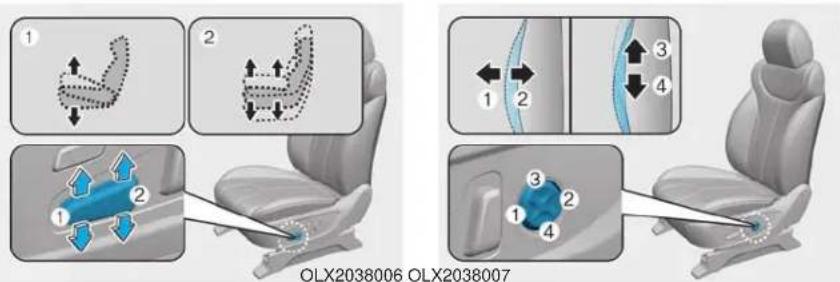
Seat cushion tilt (1)
To change the angle of the front part of the seat cushion:
Push the front portion of the control switch up to raise or down to lower the front part of the seat cushion.
Release the switch once the seat reaches the desired position.
Seat cushion height (2)
To change the height of the seat cushion:
Push the rear portion of the control switch up to raise or down to lower the height of the seat cushion.
Release the switch once the seat reaches the desired position.
Lumbar support (2way) (for driver's seat)
The lumbar support can be adjusted by pressing the lumbar support switch.
- The lumbar support can be adjusted by pressing the lumbar support switch.
- Press the front portion of the switch (1) to increase support or the rear portion of the switch (2) to decrease support.
Lumbar support (4way) (for driver's seat) (if equipped)
The lumbar support can be adjusted by pressing the lumbar support switch.
- Press the front portion of the switch (1) to increase support or the rear portion of the switch (2) to decrease support.
• To move the support position up or down, press switch (3) or (4).
Seatback pocket
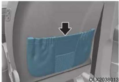
natural_image
Close-up of a blue textured surface with an arrow pointing to it, no visible text or symbolsThe seatback pocket is provided on the back of the front passenger's seatback.
WARNING
To prevent the Occupant Classification System from malfunctioning:
Do not hang onto the front pas-senger's seatback.
CAUTION
Do not put heavy or sharp objects in the seatback pockets. In an accident they could come loose from the pocket and injure occupants.
Rear Seats
Rear seat adjustment
natural_image
Interior view of a car seatbelt with two side arm diagrams showing seat positioning and usage (no text or symbols)*Above picture shows a 7-seater vehicle.
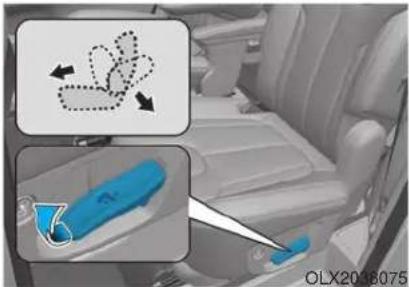
Forward and rearward (2nd row seat)
To move the seat forward or rear-ward:
- Pull the seat slide adjustment lever up and hold it.
- Slide the seat to the position you desire.
- Release the lever and make sure the seat is locked in place.
Adjust the seat before driving, and make sure the seat is locked securely by trying to move forward and rearward without using the lever. If the seat moves, it is not locked properly.
natural_image
Interior view of a car showing a blue bag being inserted into a seatbelt, with an inset diagram illustrating the mechanism (no text or symbols present)Seatback angle (2nd row seat)
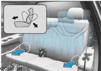
To recline the seatback:
- Pull up the seatback recline lever.
- Hold the lever and adjust the seat-back of the seat to the position you desire.
- Release the lever and make sure the seatback is locked in place. (The lever MUST return to its original position for the seatback to lock.)
natural_image
Interior view of a car showing the backrest seat, dashboard, and side-mounted sensors (no text or symbols visible)Seatback angle (3rd row seat) (Type A)
To recline the seatback:
1. Pull up the seatback recline strap.
2. Hold the strap and adjust the seat-back of the seat to the position you desire.
3. Release the strap and make sure the seatback is locked in place. (The strap MUST return to its original position for the seatback to lock.)
natural_image
Interior view of a car showing rear seats and a blue control panel with three lights (no text or symbols visible)Seatback angle (3rd row seat) (Type B)
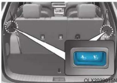
To recline the seatback:
- Push the control switch to recline the seat back.
- Release the switch once the seat-back reaches the desired position.
Walk-in seat (2nd row seat)
natural_image
Close-up of a car seatbelt with a blue arrow pointing to the side panel (no text or symbols visible)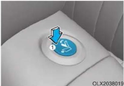
natural_image
Close-up of a car seat with a blue circular button labeled '1' and a white background (no readable text or symbols)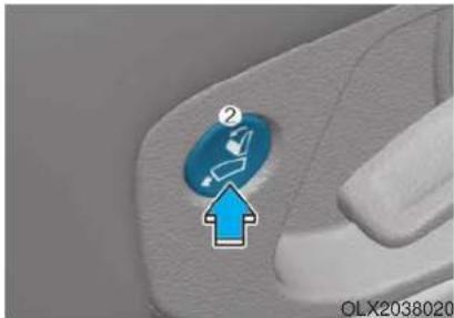
natural_image
Close-up of a hand holding a car interior with a blue circular icon and an upward arrow, no visible text or symbols.To get in or out of the 3rd row seat,
- Routing the seat belt webbing through the rear seat belt guide clip. After inserting the seat belt, tighten the belt webbing by pulling it up.
- Push the walk-in switch located on top (1) of the 2nd row seat or the side (2) of the seat bottom cushion.
- The 2nd row seatback will be folded and push the seat to the farthest forward position.
After getting in or out, slide the 2nd row seat to the farthest rearward position and pull the seatback firmly backward until it clicks into place.
Make sure that the seat is locked in place.
WARNING
Never attempt to adjust while the vehicle is moving or the 2nd row seat is occupied as the seat may suddenly move and cause the passenger on the seat to be injured.
WARNING
natural_image
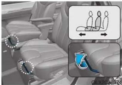
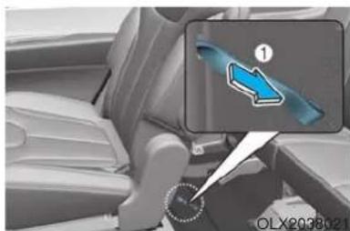
Interior view of a car showing a steering wheel and gear shift (no text or symbols visible)- If the walk-in switch does not work, pull the strap (1) located on the lower left side of the seat. Then you can move the 2nd row seat forward.
(7 passenger vehicle
- Left seat : lower right side
- Right seat : lower left side 8 passenger vehicle
- Right seat : lower left side)
- Never attempt to pull the strap (1) while the 2nd row seat is occupied as the seat may suddenly move and cause the passenger on the seat to be injured. Use only the strap when the walk-in switch does not work.
Folding the rear seat
The rear seatbacks can be folded to facilitate carrying long items or to increase the luggage capacity of the vehicle.
WARNING
- Never allow passengers to sit on top of the folded down seatback while the vehicle is moving. This is not a proper seating position and no seat belts are available for use. This could result in serious injury or death in case of an accident or sudden stop.
- Objects carried on the folded down seatback should not extend higher than the top of the front seatbacks. This could allow cargo to slide forward and cause injury or damage during sudden stops.
To fold down the rear seatback:
- Set the front seatback to the upright position and if necessary, slide the front seat forward.
- Lower the rear head restraints to the lowest position.
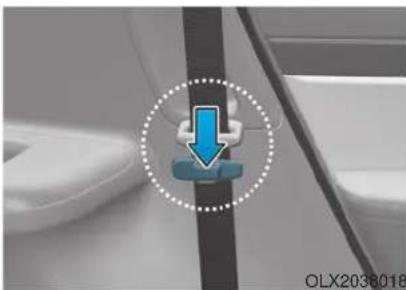
natural_image
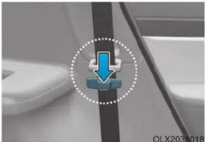
Close-up of a car's seatbelt with a blue downward arrow icon (no text or symbols)- Locate the seatbelt webbing in the guide before folding down the seatback to avoid the seatbelt system interfering with the seatback.
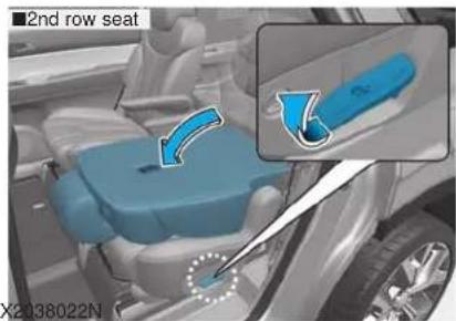
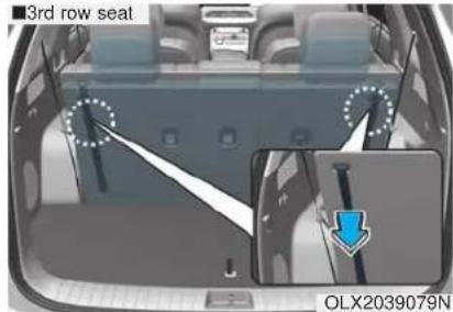
- Pull up the seatback recline lever, then fold the seat toward the front of the vehicle.
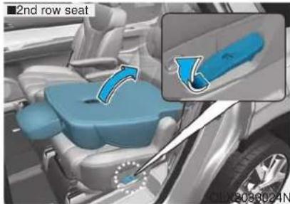
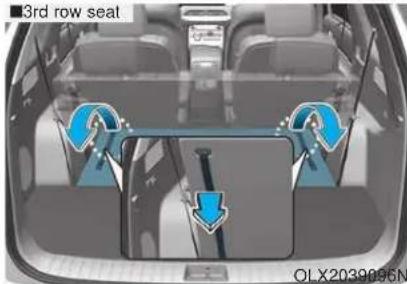
-
To use the rear seat, lift and unfold the seatback to the upright position by pulling up the recline lever. Push the seatback firmly until it clicks into place. Make sure the seatback is locked in place.
-
Return the rear seat belt to the proper position.
WARNING
When returning the rear seatback from a folded to an upright position, hold the seatback and return it slowly. Ensure that the seatback is completely locked into its upright position by pushing on the top of the seatback. In an accident or sudden stop, the unlocked seatback could allow cargo to move forward with great force and enter the passenger compartment, which could result in serious injury or death.
WARNING
Do not place objects in the rear seats, since they cannot be properly secured and may hit vehicle occupants in a collision causing serious injury or death.
WARNING
Make sure the vehicle is off, the shift button is in P (Park), and the parking brake is securely applied whenever loading or unloading cargo. Failure to take these steps may allow the vehicle to move if the shift button is inadvertently shifted to another position.
CAUTION
- Be careful when loading cargo through the rear passenger seats to prevent damage to the vehicle interior.
- When cargo is loaded through the rear passenger seats, ensure the cargo is properly secured to prevent it from moving while driving.
- Unsecured cargo in the passenger compartment can cause damage to the vehicle or injury to it's occupants.
2nd row seat folding (from outside)
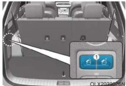
natural_image
Interior view of a car backseat showing seat compartments and a digital display with icons (no readable text or symbols)Push the 2nd row seat back folding switch (1) located on the left side of the cargo area. (L : Left seatback folding, R : Right seatback folding)
WARNING
Rear seat folding
Do not fold the rear seats(2nd & 3rd row seats), if passengers, pets or luggage are on the rear seats.
It may cause injury or damage to passengers, pets, luggage.
3rd row seat remote
folding/unfolding (if equipped)
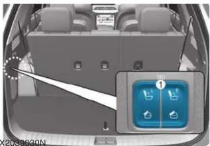
natural_image
Top-down view of a car backseat with a highlighted interior panel showing icons (no readable text or symbols)Push the 3rd row seat back folding switch (1) located on the left side of the cargo area. (L : Left seatback folding/unfolding, R : Right seatback folding/unfolding)
You can also fold or unfold the left or right seatback of the 3rd row seat by touching the menu (All menus → Setup → Vehicle in the Infotainment system).
For more details, refer to the separately supplied Multimedia manual with your vehicle.
The 3rd row seat that is remotely folded or unfolded, is controlled only when the shift button is in "P" with Start ON, or the shift button is in "N" and the parking brake is in "ON."
However, the seat is controlled at any condition in Start OFF state. When the vehicle moves or shifts while the seat is being controlled, the seat may stop operation.
When you press the switch once more while folding and unfolding the seat, operation stops. When you press the switch again, the operation resumes.
With the seat folded, when you press the angle adjusting switch, the seat is unfolded.
CAUTION
Without starting the engine, the 3rd row seat can be folded or unfolded. When this is attempted more than 10 times, the battery may discharge prematurely.
Do not apply excessive force to the 3rd row seat while in operation. It may damage the seat.
When you operate the seat over 5 times with no rest, the electric motor may be overloaded. In this case, the seat changes to overheat prevention mode. Then you cannot operate the seat by pressing the switch. Leave the seat for over 1 minute for later operation.
Detection of object caught
While folding or unfolding the 3rd row seat, when a consistent force is detected, the seat returns to its original position or stops operation.
However, this function may not work when the detected resistance is below a specific level or the seat is almost folded or unfolded. When a strong impact is applied to the seat, the object detection function may be activated even if no obstacle is present.
When any object caught is detected multiple times while operating the seat once, folding and unfolding are repeated consecutively and then the operation may stop. In this case, check that any object is caught and then operate the switch again to check for abnormality.
When the object detection is enabled, the angle of the seat back may be changed. When you operate the seat once by pressing the folding button, the angle of the seat back is reset.
WARNING
Do not place any part of your body or anything in the operating area to intentionally check the detection of any object caught.
For safety, when folding or unfolding the 3rd row seat, make sure that there is no part of body or object. To prevent damage to the seatbelt, insert it into its holder and store it in the retractor inside a seat.
When the child restraint system (CRS) is installed on the 3rd row seat, remove the CRS and then operate the seat.
When there is any object on the cushion of the 3rd row seat, remove it and then operate the seat.
To avoid interference with a front seat, keep the backrest of the front seat straight and move it forward for smooth operation.
Armrest (2nd row, 8 passengers vehicle)
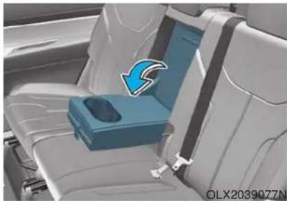
natural_image
Interior view of a car seat with a blue-labeled tray and arrow indicating rotation (no text or symbols)The armrest is located in the center of the rear seat. Use the strap in the center of the armrest to pull it down.
Armrest (2nd row, 7 passengers vehicle)
OLX2038017
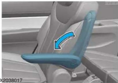
natural_image
Close-up of a blue ergonomic chair seat with a blue arrow indicating rotation (no text or symbols)Pull the armrest down from the seat-back to use it.
Rear occupant alert system (if equipped)
This function alerts the driver when exiting the vehicle to check the 2nd row seat.
If the rear doors are open prior to driving the vehicle, after driving when the vehicle is turned off, a warning message appears in the cluster to give a first warning. If the movement is detected in the 2nd row seat after you lock all doors, a second warning alerts you.
Make sure to check for passengers in the 2nd row seat before you get out.
For more details, refer to the "Rear Occupant Alert System" in chapter 3.
Head Restraints
The vehicle's front and rear seats have adjustable head restraints. The head restraints provide comfort for passengers, but more importantly they are designed to help protect passengers from whiplash and other neck and spinal injuries during an accident, especially in a rear impact collision.
WARNING
To reduce the risk of serious injury or death in an accident, take the following precautions when adjusting your head restraints:
• Always properly adjust the head restraints for all passengers BEFORE starting the vehicle.
- NEVER let anyone ride in a seat with the head restraints removed or reversed.
natural_image
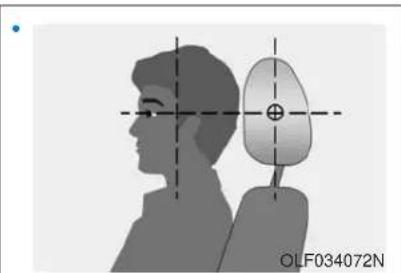
Silhouette of a person facing the side of a curved object with crosshair alignment lines (no text or symbols)Adjust the head restraints so the middle of the head restraint is at the same height as the height of the top of the eyes.
- NEVER adjust the head restraint position of the driver's seat when the vehicle is in motion.
- Adjust the head restraint as close to the passenger's head as possible. Do not use a seat cushion that holds the body away from the seatback.
• Make sure the head restraint locks into position after adjusting it.
NOTICE
To prevent damage, NEVER hit or pull on the head restraints.
CAUTION
When there is no occupant in the rear seats, adjust the height of the head restraint to the lowest position. The rear seat head restraint can reduce the visibility of the rear area.
Front seat head restraints
natural_image
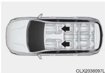
Top-down architectural rendering of a car showing its front and rear seats with two black arrows indicating specific seating areas (no text or symbols present)The vehicle's front and passenger's seats are equipped with adjustable head restraints for the passengers safety and comfort.
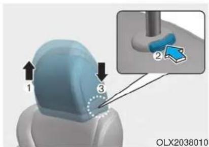
Adjusting the height up and down To raise the head restraint:
- Pull it up to the desired position (1).
To lower the head restraint:
- Push and hold the release button (2) on the head restraint support.
- Lower the head restraint to the desired position (3).
natural_image
Illustration of a hand holding a car with a blue prohibition symbol (no text or labels on the diagram itself)NOTICE
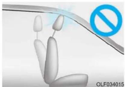
If you recline the seatback towards the front with the head restraint and seat cushion raised, the head restraint may come in contact with the sunvisor or other parts of the vehicle.
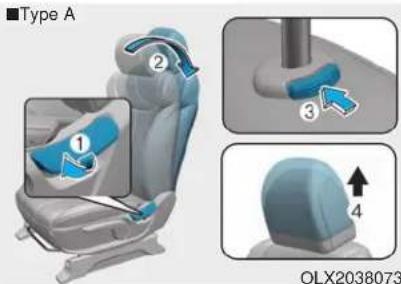
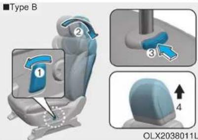
Removal/Reinstallation
To remove the head restraint:
- Recline the seatback (2) rearward using the seatback angle lever/ switch (1).
-
Raise the head restraint as far as it can go.
-
Press the head restraint release button (3) while pulling the head restraint up (4).
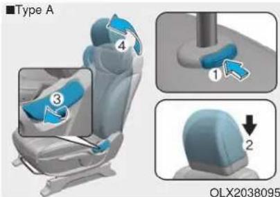
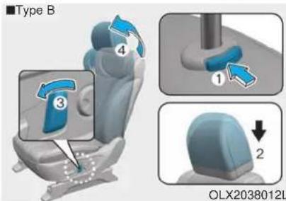
To reinstall the head restraint:
-
Put the head restraint poles (2) into the holes while pressing the release button (1).
-
Adjust the head restraint to the appropriate height.
- Adjust the seatback (4) forward using the seatback angle lever/switch (3).
Rear seat head restraints
natural_image
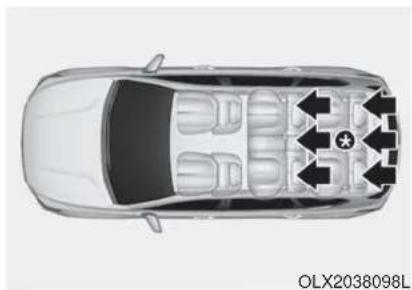
Top-down diagram of a car showing interior seating layout with directional arrows and star symbol (no text or labels)*: For 8 passengers vehicle
The rear seats are equipped with head restraints in all the seating positions for the passenger's safety and comfort.
CAUTION
- Adjust the head restraint so the middle of the head restraint is at the same height as the height of the top of the eyes.
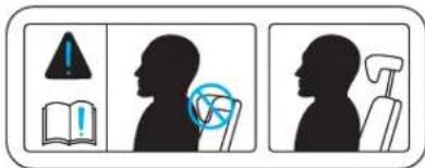
- When seated on the rear seat, do not adjust the height of the head restraint to the lowest position.
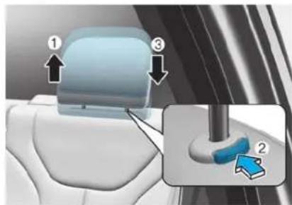
Adjusting the height up and down
To raise the head restraint:
- Pull it up to the desired position (1).
To lower the head restraint:
-
Push and hold the release button (2) on the head restraint support.
-
Lower the head restraint to the desired position (3).
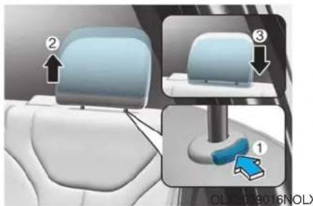
Removal/Reinstallation
To remove the head restraint:
- Raise the head restraint as far as it can go.
- Press the head restraint release button (1) while pulling the head restraint up (2).
To reinstall the head restraint:
- Put the head restraint poles into the holes (3) while pressing the release button (1).
- Adjust the head restraint to the appropriate height.
Folding 3rd row headrest (except for center)
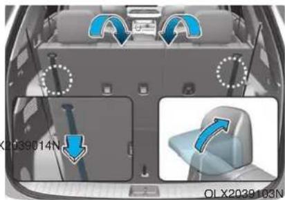
The headrest will fold down automatically when folding the seatback.
To fold the headrest manually:
- Pull the strap.
To unfold the headrest manually: - Raise the headrest manually.
Always be sure the headrest has locked into position after you return the seatback.
Seat Warmers and Air Ventilation Seats
Seat warmers (if equipped)
Seat warmers are provided to warm the seats during cold weather.
WARNING
The seat warmers can cause a SERIOUS BURN, even at low temperatures and especially if used for long periods of time.
Passengers must be able to feel if the seat is becoming too warm so they can turn it off, if needed.
People who cannot detect temperature change or pain to the skin should use extreme caution, especially the following types of passengers:
• Infants, children, elderly or disabled persons, or hospital outpatients.
• People with sensitive skin or who burn easily.
• Fatigued individuals.
- Intoxicated individuals.
• People taking medication that can cause drowsiness or sleepiness.
WARNING
NEVER place anything on the seat that insulates against heat when the seat warmer is in operation, such as a blanket or seat cushion. This may cause the seat warmer to overheat, causing a burn or damage to the seat.
NOTICE
To prevent damage to the seat warmers and seats:
- Never use a solvent such as paint thinner, benzene, alcohol or gasoline to clean the seats.
- Do not place heavy or sharp objects on seats equipped with seat warmers.
- Do not change the seat cover. It may damage the seat warmer.
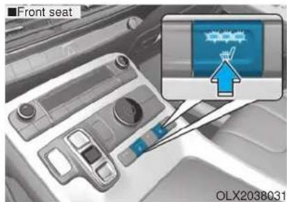
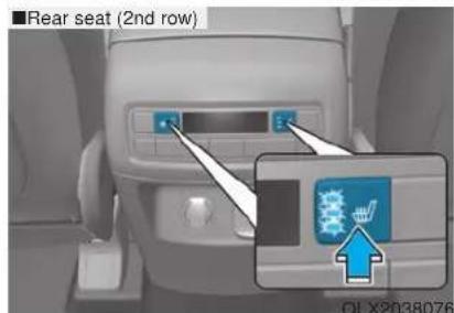
While the engine is running, push either of the switches to warm the driver's seat or front passenger's seat.
During mild weather or under conditions where the operation of the seat warmer is not needed, keep the switches in the OFF position.
• Each time you push the switch, the temperature setting of the seat changed as shown below:
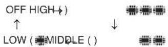
- When pressing the switch for more than 1.5 seconds with the seat warmer operating, the seat warmer will turn OFF.
- The seat warmer defaults to the OFF position whenever the vehicle is turned on.
i Information
With the seat warmer switch in the ON position, the heating system in the seat turns off or on automatically depending on the seat temperature.
Front air ventilation seat (if equipped)
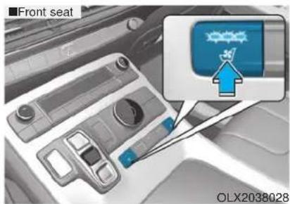
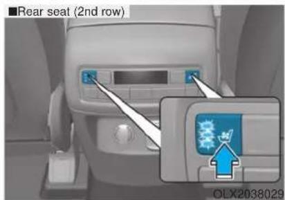
The air ventilation seats are provided to cool the front seats by blowing air through small vent holes on the surface of the seat cushions and seat-backs.
When the operation of the air ventilation seat is not needed, keep the switches in the OFF position.
While the engine is running, push the switch to cool the driver's seat or the front passenger's seat.
• Each time you push the switch, the airflow changes as follows:
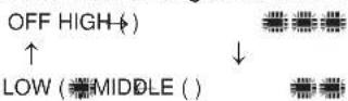
- When pressing the switch for more than 1.5 seconds with the air ventilation seat operating, the operation will turn OFF.
- The air ventilation seat defaults to the OFF position whenever the vehicle is turned on.
i Information
- If the outside temperature is under approximately 33^ (2^) , the air ventilation seat may not operate.
- Use the air ventilation seat when the climate control system is on. Using the air ventilation seat for prolonged periods of time with the climate control system off could cause the climate control seat performance to be reduced.
NOTICE
To prevent damage to the air ventilation seat:
- Use the air ventilation seat ONLY when the climate control system is on. Using the air ventilation seat for prolonged periods of time with the climate control system off could cause the air ventilation seat to malfunction.
- Never use a solvent such as paint thinner, benzene, alcohol or gasoline to clean the seats.
- Avoid spilling liquids on the surface of the front seats and seat-backs; this may cause the air vent holes to become blocked and not work properly.
- Do not place materials such as plastic bags or newspapers under the seats. They may block the air intake causing the air vents to not work properly.
- Do not change the seat covers. It may damage the air ventilation seat.
- If the air vents do not operate, restart the vehicle. If there is no change, have the vehicle inspected by an authorized HYUNDAI dealer.
SEAT BELTS
This section describes how to use the seat belts properly. It also describes some of the things to avoid when using seat belts.
Seat Belt Safety Precautions
Always fasten your seat belt and make sure all passengers have fastened their seat belts before starting any trip. Air bags are designed to supplement the seat belt as an additional safety device, but they are not a substitute. Most states require all occupants of a vehicle to wear seat belts.
WARNING
Seat belts must be used by ALL passengers whenever the vehicle is moving. Take the following precautions when adjusting and wearing seat belts:
• ALWAYS properly restrain children under age 13 in the rear seats.
- NEVER allow children to ride in the front passenger seat. If a child age 13 or older must be seated in the front seat, move the seat as far back as possible and properly restrain them in the seat.
- NEVER allow an infant or child to be carried on an occupant's lap.
- NEVER ride with the seatback reclined when the vehicle is moving.
- Do not allow children to share a seat or seat belt.
- Do not wear the shoulder belt under your arm or behind your back.
• Always wear both the shoulder portion and lap portion of the lap/shoulder belt. - Do not use the seat belt if it is twisted. A twisted seat belt will not protect you properly in an accident.
-
Do not use a seat belt if the webbing or hardware is damaged.
-
Do not latch the seat belt into the buckles of other seats.
- NEVER unfasten the seat belt while driving. This may cause loss of vehicle control resulting in an accident.
• Make sure there is nothing in the buckle interfering with the seat belt latch mechanism. This may prevent the seat belt from fastening securely. - No modifications or additions should be made by the user which will either prevent the seat belt adjusting devices from operating to remove slack, or prevent the seat belt assembly from being adjusted to remove slack.
WARNING
Damaged seat belts and seat belt assemblies will not operate properly. Always replace:
- Frayed, contaminated, or damaged webbing
- Damaged hardware
- The entire seat belt assembly after it has been worn in an accident, even if damage to webbing or assembly is not apparent
Seat Belt Warning Light
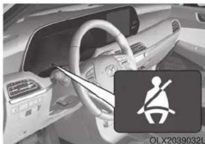
Seat belt warning light
natural_image
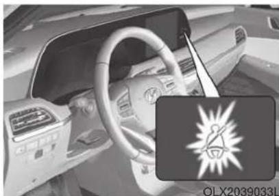
Interior view of a car showing steering wheel and dashboard (no visible text or symbols)Driver's seat belt warning
As a reminder to the driver, the seat belt warning light will illuminate for approximately 6 seconds each time you place the ignition switch to the ON position regardless of belt fastening. At this time, if the seat belt is not fastened a warning chime will sound for 6 seconds.
If you continue not to fasten the seat belt and you drive over 6 mph (9 km/h), the warning light will stay illuminated.
If you continue not to fasten the seat belt and you drive over 12 mph (20 km/h) the seat belt warning chime will sound for approximately 100 seconds and the corresponding warning light will blink.
If you unfasten the seat belt while driving under 12 mph (20 km/h), the seat belt warning light will illuminate until the seat belt is fastened.
If you unfasten the seat belt while driving over 12 mph (20 km/h), the seat belt warning chime will sound for approximately 100 seconds and the corresponding warning light will blink.
natural_image
Interior view of a car dashboard with steering wheel and illuminated logo (no readable text or symbols)Front passenger's seat belt warning As a reminder to the front passenger, the front passenger's seat belt warn- ing lights will illuminate for approxi- mately 6 seconds each time you place the ignition switch to the ON position regardless of belt fastening.
If you continue not to fasten the seat belt and you drive over 6 mph (9 km/h), the warning light will stay illuminated.
If you continue not to fasten the seat belt and you drive over 12 mph (20 km/h) the seat belt warning chime will sound for approximately 100 seconds and the corresponding warning light will blink.
If you unfasten the seat belt while driving under 12 mph (20 km/h) the seat belt warning light will illuminate until the seat belt is fastened.
If you unfasten the seat belt while driving over 12 mph (20 km/h), the seat belt warning chime will sound for approximately 100 seconds and the corresponding warning light will blink.
i Information
- Although the front passenger seat is not occupied, the seat belt warning light will blink or illuminate for 6 seconds.
Also, when the front passenger gets off the vehicle while the warning is activating, the warning may continue for 6 seconds even after the passenger gets off. - The front passenger's seat belt warning light may not properly operate if the front passenger does not sit properly in the seat.
- The front passenger's seat belt warning may operate when luggage, electronic device, etc. are placed on the front passenger seat.
Rear passenger's seat belt warning
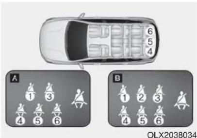
*7 passengers (A)
2nd row : 1, 3
3rd row : 4, 5, 6
*8 passengers (B)
- 2nd row : 1, 2, 3
- 3rd row : 4, 5, 6
As a reminder to the rear passenger, the rear passenger's seat belt warning lights will illuminate for approximately 6 seconds each time you turn the ignition switch ON regardless of belt fastening.
If the seat belt is not fastened when the ignition switch is turned ON or if it is disconnected after the ignition switch is turned ON, the seat belt warning light will illuminate until the belt is fastened.
If you start to drive without the seat belt fastened or you unfasten the seat belt when you drive under 12 mph (20 km/h), the corresponding warning light will continue to illuminate until you fasten the seat belt.
If you continue to drive without the seat belt fastened or you unfasten the seat belt when you drive over 12 mph (20 km/h), the seat belt warning chime will sound for approximately 35 seconds and the corresponding warning light will blink.
WARNING
Riding in an improper position adversely affects the rear passenger's seat belt warning system.
It is important for the driver to instruct the passenger to properly be seated as instructed in this manual.
i Information
- Although the rear passenger's seat is not occupied, the seat belt warning light will blink or illuminate for 6 seconds.
• The rear passenger's seat belt warning may operate when luggage, laptop or other electronic device is placed on the rear passenger seat.
Seat Belt Restraint System
WARNING
Improperly positioned seat belts may increase the risk of serious injury in an accident. Take the following precautions when adjusting the seat belt:
- Position the lap portion of the seat belt as low as possible across your hips, not on your waist, so that it fits snugly.
- Position one arm under the shoulder belt and the other over the belt, as shown in the illustration.
• Always position the shoulder belt anchor into the locked position at the appropriate height. - Never position the shoulder belt across your neck or face.
Seat Belt-Driver's 3-point system with emergency locking retractor
natural_image
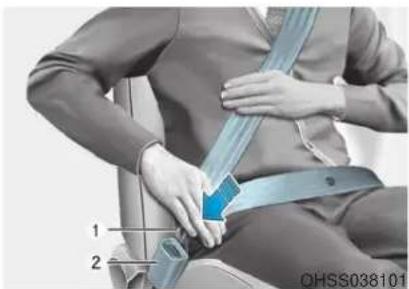
Person wearing a seatbelt and adjusting a blue belt, no visible text or symbolsTo fasten your seat belt:
Pull the seat belt out of the retractor and insert the metal tab (1) into the buckle (2). There will be an audible "click" when the tab locks into the buckle.
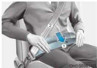
natural_image
Person sitting on a car seat with a blue medical device attached, no visible text or symbolsYou should place the lap belt (1) portion across your hips and the shoulder belt (2) portion across your chest.
The seat belt automatically adjusts to the proper length after the lap belt portion is adjusted manually so that it fits snugly around your hips. If you lean forward in a slow, easy motion, the belt will extend and move with you.
If there is a sudden stop or impact, the belt will lock into position. It will also lock if you try to lean forward too quickly.
NOTICE
If you are not able to smoothly pull enough of the seat belt out from the retractor, firmly pull the seat belt out and release it. After release, you will be able to pull the belt out smoothly.
Height adjustment
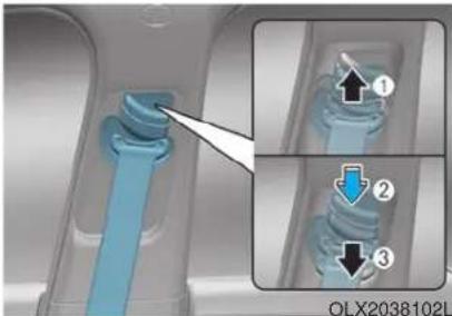
You can adjust the height of the shoulder belt anchor to one of the three different positions for maximum comfort and safety.
The shoulder portion should be adjusted so it lies across your chest and midway over your shoulder nearest the door, not over your neck.
natural_image
Close-up of a blue mechanical component being inserted, with inset showing three labeled parts (no text or symbols on the component itself)To adjust the height of the seat belt anchor, lower or raise the height adjuster into an appropriate position.
To raise the height adjuster, pull it up (1). To lower it, push it down (3) while pressing the height adjuster button (2).
Release the button to lock the anchor into position. Try sliding the height adjuster to make sure that it has locked into position.
natural_image
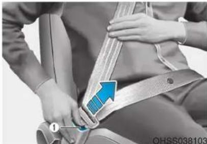
Person adjusting a seatbelt with a blue arrow indicating the angle (no text or symbols visible)To release your seat belt:
Press the release button (1) in the locking buckle.
When it is released, the belt should automatically draw back into the retractor. If this does not happen, check the belt to be sure it is not twisted, then try again.
Rear Seat Belt – Passenger's 3-point system with convertible locking retractor
This type of seat belt combines the features of both an emergency locking retractor seat belt and an automatic locking retractor seat belt. Convertible retractor type seat belts are installed in the rear seat positions to help accommodate the installation of child restraint systems. Although a convertible retractor is also installed in the front passenger seat position, NEVER place any infant/child restraint system in the front seat of the vehicle.
To fasten your seat belt:
Pull the seat belt out of the retractor and insert the metal tab into the buckle. There will be an audible "click" when the tab locks into the buckle. When not securing a child restraint, the seat belt operates in the same way as the driver's seat belt (Emergency Locking Retractor Type). It automatically adjusts to the proper length only after the lap belt portion of the seat belt is adjusted manually so that it fits snugly across your hips.
When the seat belt is fully extended from the retractor to allow the installation of a child restraint system, the seat belt operation changes to allow the belt to retract, but not to extend (Automatic Locking Retractor Type). Refer to the "Using a Child Restraint System" section in this chapter.
NOTICE
Although the seat belt retractor provides the same level of protection for seated passengers in either emergency or automatic locking modes, the emergency locking mode allows seated passengers to move freely in their seat while keeping some tension on the belt. During a collision or sudden stop, the retractor automatically locks the belt to help restrain your body.
To deactivate the automatic locking mode, unbuckle the seat belt and allow the belt to fully retract.
natural_image
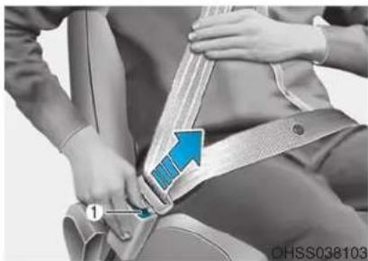
Close-up of a person's seatbelt buckle being adjusted, showing blue arrow indicating direction (no text or symbols)To release your seat belt:
Press the release button (1) in the locking buckle.
When it is released, the belt should automatically draw back into the retractor. If this does not happen, check the belt to be sure it is not twisted, then try again.
Rear center seatbelt (3rd row)
natural_image
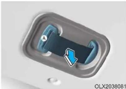
Close-up of a blue arrow pointing to a dark blue object inside a metallic container (no text or symbols visible)To fasten your seatbelt:
- Extract the tongue plate (A) from the hole on the belt assembly cover.
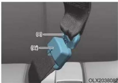
- Insert the tongue plate (A) into the buckle (A') until an audible "click" is heard, indicating the latch is locked. Make sure the belt is not twisted.
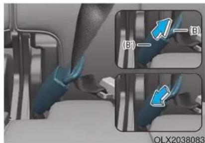
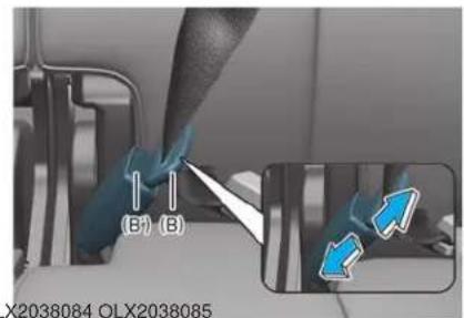
- Pull out the tongue plate (B) from the pocket. Pull the tongue plate (B) and insert it into the buckle (B') until an audible "click" is heard, indicating the latch is locked. Make sure the belt is not twisted.
To release your seatbelt:
- Press the release button on the buckle (B') and remove the tongue plate (B).
When using the rear center seat belt, the buckle with the "CENTER" mark must be used.
i Information
If you are not able to pull out the safety belt from the retractor, firmly pull the belt out and release it. After release, you will be able to pull the belt out smoothly.
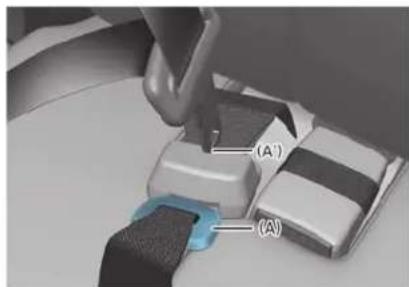
- To retract the rear center seatbelt, insert the tongue plate into the web release hole (A'). Pull up on the seat belt web and allow the webbing to retract automatically. Insert the tongue plate (A) into the hole on the belt assembly cover.
Stowing the rear seat belt
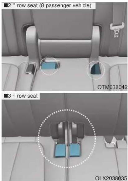
• The rear seat belt buckles can be stowed in the pocket between the rear seatback and cushion when not in use.
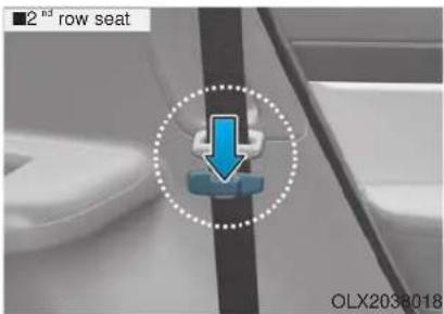
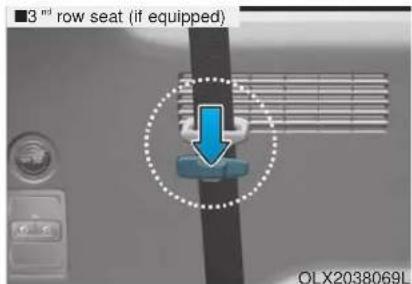
- Routing the seat belt webbing through the rear seat belt guides will help keep the belts from being trapped behind or under the seats. After inserting the seat belt, tighten the belt webbing by pulling it up.
CAUTION
When using the seat belt, use it after taking it out of the guides. If you pull the seat belt when it is stored in the guides, it may damage the guides and/or belt webbing.
Pre-tensioner seat belt (Driver and front passenger)
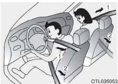
Your vehicle is equipped with driver's and front passenger's Pre-tensioner Seat Belts (Retractor Pretensioner).
The purpose of the pre-tensioner is to make sure the seat belts fit tightly against the occupant's body in certain frontal or side collision(s).
When the vehicle stops suddenly, or if the occupant tries to lean forward too quickly, the seat belt retractor will lock into position. In certain frontal or side collision(s), the pre-tensioner will activate and pull the seat belt into tighter contact against the occupant's body.
(1) Retractor Pretensioner
The purpose of the retractor pretensioner is to make sure that the shoulder belts fit in tightly against the occupant's upper body in certain frontal or side collision(s).
If the system senses excessive tension on the driver or passenger's seat belt when the pre-tensioner system activates, the load limiter inside the retractor pre-tensioner will release some of the pressure on the affected seat belt.
WARNING
• Always wear your seat belt and sit properly in your seat.
- Do not use the seat belt if it is loose or twisted. A loose or twisted seat belt will not protect you properly in an accident.
- Do not place anything near the buckle. This may adversely affect the buckle and cause it to function improperly.
• Always replace your pre-tensioners after activation or an accident.
- NEVER inspect, service, repair or replace the pre-tensioners yourself. This must be done by an authorized HYUNDAI dealer.
- Do not hit the seat belt assemblies.
WARNING
Do not touch the pre-tensioner seat belt assemblies for several minutes after they have been activated. When the pre-tensioner seat belt mechanism deploys during a collision, the pre-tensioners become hot and can burn you.
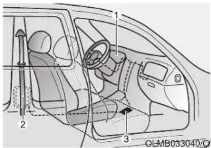
The Pre-Tensioner Seat Belt System consists mainly of the following components. Their locations are shown in the illustration above:
- SRS air bag warning light
- Retractor pre-tensioner
- SRS control module
NOTICE
The sensor that activates the SRS air bag is connected with the pre-tensioner seat belts. The SRS air bag warning light on the instrument panel will illuminate for approximately 6 seconds after the ignition switch is in the ON position, and then it should turn off.
If the pre-tensioner is not working properly, the warning light will illuminate even if the SRS air bag is not malfunctioning. If the warning light does not illuminate, stays illuminated or illuminates when the vehicle is being driven, have an authorized HYUNDAI dealer inspect the pre-tensioner seat belts and SRS air bags as soon as possible.
NOTICE
- Both the driver's and front passenger's pre-tensioner seat belts may be activated in certain frontal or side collisions or rollovers.
- When the pre-tensioner seat belts are activated, a loud noise may be heard and fine dust, which may appear to be smoke, may be visible in the passenger compartment. These are normal operating conditions and are not hazardous.
- Although it is non-toxic, the fine dust may cause skin irritation and should not be inhaled for prolonged periods. Wash all exposed skin areas thoroughly after an accident in which the pre-tensioner seat belts were activated.
Additional Seat Belt Safety Precautions
Seat belt use during pregnancy
The seat belt should always be used during pregnancy. The best way to protect your unborn child is to protect yourself by always wearing the seat belt.
Pregnant women should always wear a lap-shoulder seat belt. Place the shoulder belt across your chest, routed between your breasts and away from your neck. Place the lap belt line so that it fits snugly and as low as possible across the hips, not across the abdomen.
WARNING
• A pregnant woman or a patient is more vulnerable to any imapcts on the abdomen during an abrupt stop or accident. If you are in an accident while pregnant, we recommend you consult your doctor.
• To reduce the risk of serious injury or death to an unborn child during an accident, pregnant women should NEVER place the lap portion of the seat belt above or over the area of the abdomen where the unborn child is located.
Seat belt use and children
Infant and small children
All 50 states have child restraint laws which require children to travel in approved child restraint devices, including booster seats. The age at which seat belts can be used instead of child restraints differs among states, so you should be aware of the specific requirements in your state, and where you are travelling. Infant and child restraints must be properly placed and installed in a rear seat. For more information refer to the "Child Restraint Systems" section in this chapter.
WARNING
ALWAYS properly restrain infants and small children in a child restraint appropriate for the child's height and weight.
To reduce the risk of serious injury or death to a child and other passengers, NEVER hold a child in your lap or arms when the vehicle is moving. The violent forces created during an accident will tear the child from your arms and throw the child against the interior of the vehicle.
Small children are best protected from injury in an accident when properly restrained in the rear seat by a child restraint system that meets the requirements of the Federal Motor Vehicle Safety Standards. Before buying any child restraint system, make sure that it has a label certifying that it meets Federal Motor Vehicle Safety Standard FMVSS 213. The restraint must be appropriate for your child's height and weight. Check the label on the child restraint for this information. Refer to the "Child Restraint Systems" section in this chapter.
Larger children
Children under age 13 and who are too large for a booster seat must always occupy the rear seat and use the available lap/shoulder belts. A seat belt should lie across the upper thighs and be snug across the shoulder and chest to restrain the child safely. Check belt fit periodically. Children are afforded the most safety in the event of an accident when they are restrained by a proper restraint system and/or seat belts in the rear seat. Always have the LATCH system inspected by your authorized HYUNDAI dealer after an accident. An accident can damage the LATCH system and may not properly secure the child restraint.
If a larger child over age 13 must be seated in the front seat, the child must be securely restrained by the available lap/shoulder belt and the seat should be placed in the rearmost position.
If the shoulder belt portion slightly touches the child's neck or face, try placing the child closer to the center of the vehicle. If the shoulder belt still touches their face or neck they need to be returned to an appropriate booster seat in the rear seat.
WARNING
• Always make sure children are wearing their seat belts and that they are properly adjusted before driving.
- NEVER allow the shoulder belt to contact the child's neck or face.
- Do not allow more than one child to use a single seat belt.
Transporting an injured person
A seat belt should be used when an injured person is being transported. Consult a physician for specific recommendations.
One person per belt
Two people (including children) should never attempt to use a single seat belt. This could increase the severity of injuries in case of an accident.
Do not lie down
Sitting in a reclined position when the vehicle is in motion can be dangerous. Even when buckled up, the protections of your restraint system (seat belts and air bags) is greatly reduced by reclining your seatback.
To reduce the chance of injuries in the event of an accident and to achieve the maximum effectiveness of the restraint system, all passengers should be sitting up and the front and rear seats should be in an upright position when the car is moving.
A seat belt cannot provide proper protection if the person is lying down in the rear seat or if the front or rear seats are in a reclined position.
WARNING
- NEVER ride with a reclined seatback when the vehicle is moving.
- Riding with a reclined seatback increases your chance of serious or fatal injuries in the event of a collision or sudden stop.
- Drivers and passengers should always sit well back in their seats, properly belted, and with the seatbacks upright.
Care of Seat Belts
Seat belt systems should never be disassembled or modified. In addition, care should be taken to assure that seat belts and belt hardware are not damaged by seat hinges, doors or other abuse.
Periodic inspection
All seat belts should be inspected periodically for wear or damage of any kind. Any damaged parts should be replaced as soon as possible by an authorized HYUNDAI dealer.
Keep belts clean and dry
Seat belts should be kept clean and dry. If belts become dirty, they can be cleaned by using a mild soap solution and warm water. Bleach, dye, strong detergents or abrasives should not be used because they may damage and weaken the fabric.
When to replace seat belts
The entire seat belt assembly or assemblies should be replaced if the vehicle has been involved in an accident. This should be done even if no damage is visible. Additional questions concerning seat belt operation should be directed to an authorized HYUNDAI dealer.
CHILD RESTRAINT SYSTEM (CRS)
Children Always in the Rear
WARNING
Always properly restrain children in the rear seats of the vehicle.
Children of all ages are safer when restrained in the rear seat. A child riding in the front passenger seat can be forcefully struck by an inflating air bag resulting in SERIOUS INJURY or DEATH.
Children under age 13 must always ride in the rear seats and must always be properly restrained to minimize the risk of injury in an accident, sudden stop or sudden maneuver. According to accident statistics, children are safer when properly restrained in the rear seats than in the front seat. Even with air bags, children can be seriously injured or killed. Children too large for a child restraint must use the seat belts provided.
All 50 states have child restraint laws which require children to travel in approved child restraint devices. The laws governing the age or height/weight restrictions at which seat belts can be used instead of child restraints differs among states, so you should be aware of the specific requirements in your state, and where you are travelling.
Child restraint systems must be properly placed and installed in the rear seat. You must use a commercially available child restraint system that meets the requirements of the Federal Motor Vehicle Safety Standards (FMVSS 213).
Child restraint systems are generally designed to be secured in a vehicle seat by lap belt portion of a lap/shoulder belt, or by a LATCH system in the rear seats of the vehicle.
Child restraint system (CRS)
Infants and younger children must be restrained in an appropriate rear-facing or forward-facing CRS that has first been properly secured to the rear seat of the vehicle. Read and comply with the instructions for installation and use provided by the manufacturer of the child restraint.
WARNING
An improperly secured child restraint can increase the risk of SERIOUS INJURY or DEATH in an accident. Always take the following precautions when using a child restraint system:
- NEVER install a child or infant restraint in the front passenger's seat.
• Always properly secure the child restraint to a rear seat of the vehicle.
• Always follow the child restraint system manufacturer's instructions for installation and use.
• Always properly restrain your child in the child restraint.
- If the vehicle head restraint prevents proper installation of a child seat (as described in the child restraint system manual), the head restraint of the respective seating position shall be readjusted or entirely removed.
- Do not use an infant carrier or a child safety seat that "hooks" over a seatback, it may not provide adequate protection in an accident.
• After an accident, have a HYUNDAI dealer check the child restraint system, seat belts, lower anchors and upper tether anchors.
WARNING
- Be especially careful when installing a child restraint on the center seating position in the second row as it is narrower than the outboard positions. A wide child restraint installed on the center seat may cover the safety belt buckles for the other seating positions. Do not allow someone to ride in a seating position where the safety belt buckle is covered by a child restraint.
- A child restraint in the center seating position may also contact or push up against the safety belt buckles, which can damage the buckles and make them unusable or unsafe. Always check that the child restraint does not contact any of the safety belt buckles. Check the placement of the child restraint regularly to make sure that it has not shifted and come into contact with any of the safety belt buckles.
Selecting a Child Restraint System (CRS)
When selecting a CRS for your child, always:
• Make sure the CRS has a label certifying that it meets applicable Federal Motor Vehicle Safety Standards (FMVSS 213).
- Select a child restraint based on your child's height and weight. The required label or the instructions for use typically provide this information.
- Select a child restraint that fits the vehicle seating position where it will be used.
- Read and comply with the warnings and instructions for installation and use provided with the child restraint system.
Child restraint system types
There are three main types of child restraint systems: rearward-facing seats, forward-facing seats, and booster seats. They are classified according to the child's age, height and weight.
Rearward-facing child seats
WARNING
NEVER install a child or infant restraint in the front passenger's seat.
Placing a rearward-facing child restraint in the front seat can result in SERIOUS INJURY or DEATH if the child restraint is struck by an inflating air bag.
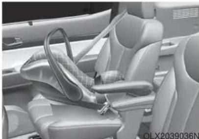
natural_image
Interior view of a car's seat and steering wheel (no visible text or symbols)A rearward-facing child seat provides restraint with the seating surface against the back of the child. The harness system holds the child in place, and in an accident, acts to keep the child positioned in the seat and reduce the stress to the neck and spinal cord.
All children under age one must always ride in a rearward-facing infant child restraint.
Convertible and 3-in-1 child seats typically have higher height and weight limits for the rearward-facing position, allowing you to keep your child rearward-facing for a longer period of time.
Continue to use a rearward-facing child seat for as long as your child will fit within the height and weight limits allowed by the child seat manufacturer. It's the best way to keep them safe. Once your child has outgrown the rearward-facing child restraint, your child is ready for a forward-facing child restraint with a harness.
WARNING
Do NOT adjust the seat when child seat is fitted. Adjusting the seat during driving can result in SERIOUS INJURY or DEATH.
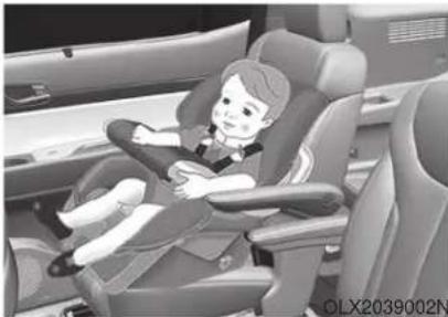
natural_image
Illustration of a child sitting in a car seat, no text or symbols visibleForward-facing child restraints
A forward-facing child seat provides restraint for the child's body with a harness. Keep children in a forward-facing child seat with a harness until they reach the top height or weight limit allowed by your child restraint's manufacturer.
Once your child outgrows the forward-facing child restraint, your child is ready for a booster seat.
Booster seats
A booster seat is a restraint designed to improve the fit of the vehicle's seat belt system. A booster seat positions the seat belt so that it fits properly over the lap of your child.
Keep your child in a booster seat until they are big enough to sit in the seat without a booster and still have the seat belt fit properly. For a seat belt to fit properly, the lap belt must lie snugly across the upper thighs, not the stomach. The shoulder belt should lie snug across the shoulder and chest and not across the neck or face. Children under age 13 must always ride in the rear seats and must always be properly restrained to minimize the risk of injury.
Installing a Child Restraint System (CRS)
WARNING
Before installing your child restraint system always:
- Read and follow the instructions provided by the manufacturer of the child restraint.
- Read and follow the instructions regarding child restraint systems in this manual.
Failure to follow all warnings and instructions could increase the risk of the SERIOUS INJURY or DEATH if an accident occurs.
WARNING
If the vehicle head restraint prevents proper installation of a child seat (as described in the child seat system manual, the head restraint of the respective seating position shall be readjusted or entirely removed.
After selecting a proper child seat for your child, check to make sure it fits properly in your vehicle. Follow the instructions provided by the manufacturer when installing the child seat. Note these general steps when installing the seat to your vehicle:
- Properly secure the child restraint to the vehicle. All child restraints must be secured to the vehicle with the lap part of a lap/shoulder belt or with the LATCH system. If using the lap/shoulder belt for your child restraint, the convertible locking retractor should be pulled all the way out to engage the "automatic locking" mode. (See page 2-54.)
- Make sure the child restraint is firmly secured. After installing a child restraint to the vehicle, push and pull the seat forward-and-back and side-to-side to verify that it is securely attached to the seat. A child restraint secured with a seat belt should be installed as firmly as possible. However, some side-to-side movement can be expected.
- Secure the child in the child restraint. Make sure the child is properly strapped in the child restraint according to the manufacturer instructions.
CAUTION
A child restraint in a closed vehicle can become very hot. To prevent burns, check the seating surface and buckles before placing your child in the child restraint.
Lower Anchors and Tether for Children (LATCH System)
The LATCH system holds a child restraint during driving and in an accident. This system is designed to make installation of the child restraint easier and reduce the possibility of improperly installing your child restraint. The LATCH system uses anchors in the vehicle and attachments on the child restraint. The LATCH system eliminates the need to use seat belts to secure the child restraint to the rear seats.
Lower anchors are metal bars built into the vehicle. There are two lower anchors for each LATCH seating position that will accommodate a child restraint with lower attachments.
To use the LATCH system in your vehicle, you must have a child restraint with LATCH attachments.
The child seat manufacturer will provide you with instructions on how to use the child seat with its attachments for the LATCH lower anchors.
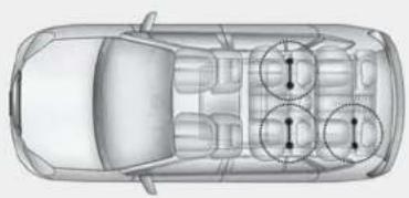
natural_image
Top-down schematic of a car showing front, rear, side, and interior compartments with circular annotations (no text or symbols)OLX2038039
LATCH anchors have been provided in the left and right outboard rear seating positions. Their locations are shown in the illustration.There are no LATCH anchors provided for the center rear seating position.
WARNING
Do not attempt to install a child restraint system using LATCH anchors in the rear center seating position. There are no LATCH anchors provided for this seat. Using the outboard seat anchors can damage the anchors which may break or fail in a collision resulting in serious injury or death.
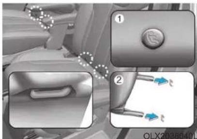
natural_image
Close-up of a car interior showing a handle and a valve, with no visible text or symbols[1]: Lower Anchor Position Indicator,
[2]: Lower Anchor
The lower anchor position indicator symbols are located on the left and right rear seat backs to identify the position of the lower anchors in your vehicle (see arrows in illustration).
The LATCH anchors are located between the seatback and the seat cushion of the rear seat left and right outboard seating positions.
Securing a child restraint with the LATCH anchors system
To install a LATCH-compatible child restraint in either of the rear outboard seating positions:
- Move the seat belt buckle away from the lower anchors.
- Move any other objects away from the anchors that could prevent a secure connection between the child restraint and the lower anchors.
- Place the child restraint on the vehicle seat, then attach the seat to the lower anchors according to the instructions provided by the child restraint manufacturer.
- Follow the child restraint instructions for properly adjusting and tightening the lower attachments on the child restraint to the lower anchors.
WARNING
Take the following precautions when using the LATCH system:
- Read and follow all installation instructions provided with your child restraint system.
• To prevent the child from reaching and taking hold of unretracted seat belts, buckle all unused rear seat belts and retract the seat belt webbing behind the child. Children can be strangled if a shoulder belt becomes wrapped around their neck and the seat belt tightens. - NEVER attach more than one child restraint to a single anchor. This could cause the anchor or attachment to come loose or break.
• Always have the LATCH system inspected by your authorized HYUNDAI dealer after an accident. An accident can damage the LATCH system and may not properly secure the child restraint.
NOTICE
The recommended weight for the LATCH system is under 65 lb (30 kg).
How to determine an appropriate child restraint weight:
Child weight + Child restraint weight < 65 lb (30kg)
Securing a child restraint seat with "Tether Anchor" system
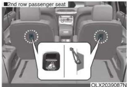
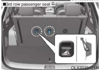
First secure the child restraint with the LATCH lower anchors or the seat belt. If the child restraint manufacturer recommends that the top tether strap be attached, attach and tighten the top tether strap to the top tether strap anchor.
Child restraint hook holders are located on the rear of the seatbacks.
WARNING
Take the following precautions when installing the tether strap:
- Read and follow all installation instructions provided with your child restraint system.
- NEVER attach more than one child restraint to a single tether anchor. This could cause the anchor or attachment to come loose or break.
- Do not attach the tether strap to anything other than the correct tether anchor. It may not work properly if attached to something else.
- Do not use the tether anchors for adult seat belts or harnesses, or for attaching other items or equipment to the vehicle.
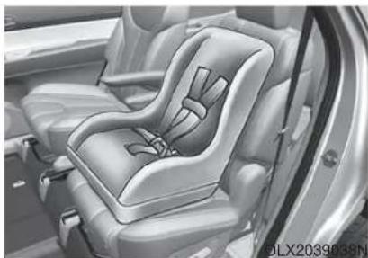
natural_image
Interior view of a car seat assembly (no text or symbols visible)To install the tether anchor:
- Route the child restraint tether strap over the child restraint seat-back. Route the tether strap under the head restraint and between the head restraint posts, or route the tether strap over the top of the vehicle seatback. Make sure the strap is not twisted.
- Connect the tether strap hook to the tether anchor, then tighten the tether strap according to the child seat manufacturer's instructions to firmly secure the child restraint to the seat.
- Check that the child restraint is securely attached to the seat by pushing and pulling the seat forward-and-back and side-to-side.
Securing a child restraint with lap/shoulder belt
When not using the LATCH system, all child restraints must be secured to a vehicle rear seat with the lap part of a lap/shoulder belt.
WARNING
ALWAYS place a rear-facing child restraint in the rear seat of the vehicle.
Placing a rear-facing child restraint in the front seat can result in serious injury or death if the child restraint is struck by an inflating air bag.
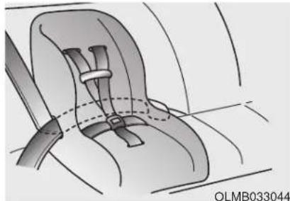
natural_image
Illustration of a car seatbelt with a belt buckle, no text or symbols presentAutomatic locking mode
Since all passenger seat belts move freely under normal conditions and only lock under extreme or emergency conditions (emergency locking mode), you must manually pull the seat belt all the way out to shift the retractor to the "Automatic Locking" mode to secure a child restraint.
The "Automatic Locking" mode will help prevent the normal movement of the child in the vehicle from causing the seat belt to loosen and compromise the child restraint system. To secure a child restraint system, use the following procedure.
To install a child restraint system on the rear seats, do the following:
- Place the child restraint system on a rear seat and route the lap/shoulder belt around or through the child restraint, following the restraint manufacturer's instructions. Be sure the seat belt webbing is not twisted.
NOTICE
When using the rear center seat belt, you should also refer to the "Rear Seat Belt – Passenger's 3-point system" section in this chapter.
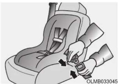
natural_image
Illustration of a person adjusting a car seatbelt using a buckle (no text or symbols present)- Fasten the lap/shoulder belt latch into the buckle. Listen for the distinct "click" sound.
i Information
Position the release button so that it is easy to access in case of an emergency.
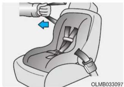
natural_image
Illustration of a car seatbelt buckle being adjusted for a hand (no text or symbols)- Pull the shoulder portion of the seat belt all the way out. When the shoulder portion of the seat belt is fully extended, it will shift the retractor to the "Automatic Locking" (child restraint) mode.
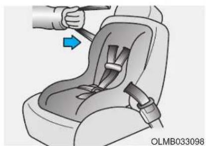
natural_image
Illustration of a car seatbelt being adjusted for a hand, showing the seatbelt and belt (no text or symbols)-
Slowly allow the shoulder portion of the seat belt to retract and listen for an audible "clicking" or "ratcheting" sound. This indicates that the retractor is in the "Automatic Locking" mode. If no distinct sound is heard, repeat steps 3 and 4.
-
Remove as much slack from the belt as possible by pushing down on the child restraint system while feeding the shoulder belt back into the retractor.
- Push and pull on the child restraint system to confirm that the seat belt is holding it firmly in place. If it is not, release the seat belt and repeat steps 2 through 6.
- Double check that the retractor is in the "Automatic Locking" mode by attempting to pull more of the seat belt out of the retractor. If you cannot, the retractor is in the "Automatic Locking" mode.
If your CRS manufacturer instructs or recommends you to use a tether anchor with the lap/shoulder belt, refer to the previous pages for more information.
NOTICE
When the seat belt is allowed to retract to its fully stowed position, the retractor will automatically switch from the "Automatic Locking" mode to the emergency lock mode for normal adult usage.
WARNING
If the retractor is not in the "Automatic Locking" mode, the child restraint can move when your vehicle turns or stops suddenly. A child can be seriously injured or killed if the child restraint is not properly anchored in the car, including manually pulling the seat belt all the way out to shift the retractor to the "Automatic Locking" mode.
To remove the child restraint, press the release button on the buckle and then pull the lap/shoulder belt out of the restraint and allow the seat belt to retract fully.
AIR BAG - ADVANCED SUPPLEMENTAL RESTRAINT SYSTEM
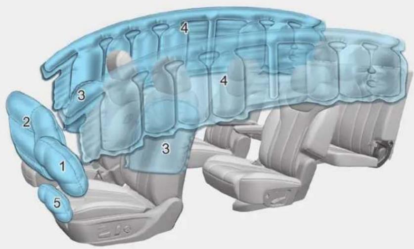
The actual air bags in the vehicle may differ from the illustration.
- Driver's front air bag
- Passenger's front air bag
- Side air bag
- Curtain air bag
- Driver's knee airbag
OLX2039041N
This vehicle is equipped with an Advanced Supplemental Air Bag System for the driver's seat and front passenger's seats.
The front air bags are designed to supplement the three-point seat belts. For these air bags to provide protection, the seat belts must be worn at all times when driving.
You can be severely injured or killed in an accident if you are not wearing a seat belt. Air bags are designed to supplement seat belts, but do not replace them. Also, air bags are not designed to deploy in every collision. In some accidents, the seat belts are the only restraint protecting you.
WARNING
AIR BAG SAFETY PRECAUTIONS
ALWAYS use seat belts and child restraints - every trip, every time, everyone! Even with air bags, you can be seriously injured or killed in a collision if you are improperly belted or not wearing your seat belt when the air bag inflates.
NEVER place a child in any child restraint or booster seat in the front passenger seat. An inflating air bag could forcefully strike the infant or child causing serious or fatal injuries.
ABC - Always Buckle Children under age 13 in the back seat. It is the safest place for children of any age to ride. If a child age 13 or older must be seated in the front seat, he or she must be properly belted and the seat should be moved as far back as possible.
All occupants should sit upright with the seatback in an upright position, centered on the seat cushion with their seat belt on, legs comfortably extended and their feet on the floor until the vehicle is parked and is turned off. If an occupant is out of position during an accident, the rapidly deploying air bag may forcefully contact the occupant causing serious or fatal injuries.
You and your passengers should never sit or lean unnecessarily close to the air bags or lean against the door or center console.
Move your seat as far back as possible from front air bags, while still maintaining control of the vehicle. The U.S. National Highway Traffic Safety Administration (NHTSA) recommends that drivers allow at least 10 inches (25 cm) between the center of the steering wheel and the chest.
Where Are the Air Bags?
Driver's and passenger's front air bags
Your vehicle is equipped with a Advanced Supplemental Restraint System (SRS) and lap/shoulder belts at both the driver and passenger seating positions.
The SRS consists of air bags which are located in the center of the steering wheel, and the passenger's side front panel pad above the glove box. The air bags are labeled with the letters "AIR BAG" embossed on the pad covers.
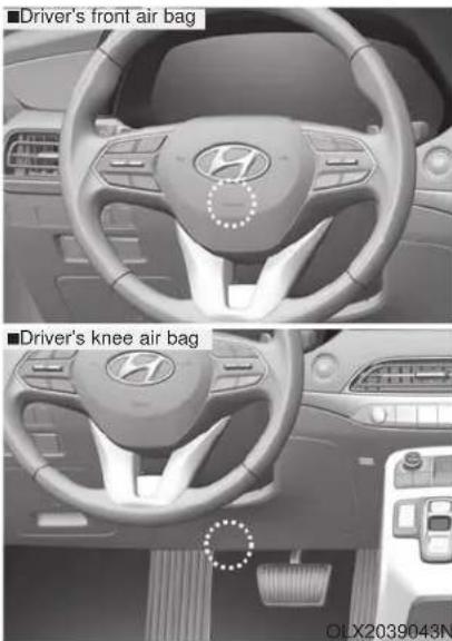
natural_image
Interior view of a car showing front and knee air bags with brand logo (no text or symbols on the dashboard itself)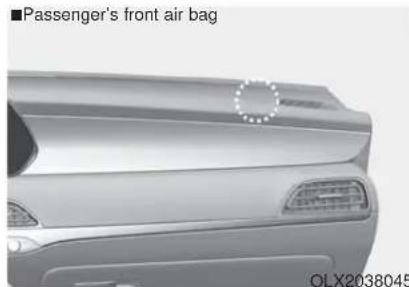
natural_image
Front view of a car showing the passenger's front air bag (no text or symbols on the car body)OLX2038045OLX2038044
The purpose of the SRS is to provide the vehicle's driver and front passengers with additional protection than that offered by the seat belt system alone.
The advanced SRS offers the ability to control the air bag inflation within two levels. A first stage level is provided for moderate-severity impacts. A second stage level is provided for more severe impacts.
According to the impact severity, the SRS Control Module (SRSCM) controls the air bag inflation. Failure to properly wear seat belts can increase the risk or severity of injury in an accident.
WARNING
To reduce the risk of serious injury or death from an inflating front air bags, take the following precautions:
- Seat belts must be worn at all times to help keep occupants positioned properly.
- Move your seat as far back as possible from front air bags, while still maintaining control of the vehicle.
- Never lean against the door or center console.
- Do not allow the front passenger to place their feet or legs on the dashboard.
- No objects (such as crash pad cover, cellular phone holder, cup holder, perfume or stickers) should be placed over or near the air bag modules on the steering wheel, instrument panel, windshield glass, and the front passenger's panel above the glove box. Such objects could cause harm if the vehicle is in a crash severe enough to cause the air bags to deploy.
Side air bags
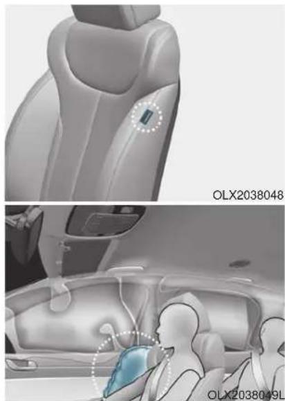
natural_image
Interior view of a car showing the backrest and dashboard with a highlighted device (no text or symbols visible)Your vehicle is equipped with a side air bag in each front seat. The purpose of the air bag is to provide the vehicle's driver and the front passenger with additional protection than that offered by the seat belt alone.
The side air bags are designed to deploy during certain side impact collisions, depending on the crash severity.
The side and curtain air bags on both sides of the vehicle may deploy if a rollover or possible rollover is detected.
The side air bags are not designed to deploy in all side impact or rollover situations.
WARNING
To reduce the risk of serious injury or death from an inflating side air bag, take the following precautions:
- Seat belts must be worn at all times to help keep occupants positioned properly.
- Do not allow passengers to lean their heads or bodies onto doors, put their arms on the doors, stretch their arms out of the window, or place objects between the doors and seats.
- Hold the steering wheel at the 9 o'clock and 3 o'clock positions, to minimize the risk of injuries to your hands and arms.
- Do not use any accessory seat covers. This could reduce or prevent the effectiveness of the system.
- Do not place any objects over the air bag or between the air bag and yourself. Also, do not attach any objects around the area the air bag inflates such as the door, side door glass, front and rear pillar.
-
Do not place any objects between the door and the seat. They may become dangerous projectiles if the side air bag inflates.
-
Do not install any accessories on the side or near the side air bags.
- Do not put any objects between the side airbag label and seat cushion. It could cause harm if the vehicle is in a crash severe enough to cause the air bags to deploy.
- Do not cause impact to the doors when the ignition switch button is in the ON position as this may cause the side air bags to inflate.
- If the seat or seat cover is damaged, have the vehicle checked and repaired by an authorized HYUNDAI dealer.
Curtain air bags
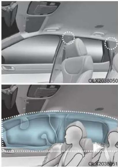
natural_image
Interior view of a car showing exterior and interior views with highlighted areas (no text or symbols)Curtain air bags are located along both sides of the roof rails above the front and rear doors.
They are designed to help protect the heads of the front seat occupants and the rear outboard seat occupants in certain side impact collisions.
The curtain air bags are designed to deploy during certain side impact collisions, depending on the crash severity.
The side and curtain air bags on both sides of the vehicle may deploy if a rollover or possible rollover is detected.
The curtain air bags are not designed to deploy in all side impact or rollover situations.
WARNING
To reduce the risk of serious injury or death from an inflating curtain air bag, take the following precautions:
- All seat occupants must wear seat belts at all times to help keep occupants positioned properly.
• Properly secure child restraints as far away from the door as possible.
- Do not place any objects over the air bag. Also, do not attach any objects around the area the air bag inflates such as the door, side door glass, front and rear pillar, roof side rail.
- Do not hang other objects except clothes, especially hard or breakable objects. In an accident, it may cause vehicle damage or personal injury.
- Do not allow passengers to lean their heads or bodies onto doors, put their arms on the doors, stretch their arms out of the window, or place objects between the doors and seats.
- Do not open or repair the side curtain air bags.
How Does the Air Bag System Operate?
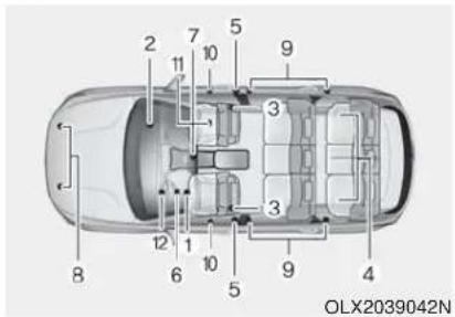
The SRS consists of the following components:
- Driver's front air bag module
- Passenger's front air bag module
- Side air bag modules
- Curtain air bag modules
- Retractor pre-tensioner
- Air bag warning light
- SRS control module (SRSCM)/Rollover sensor
- Front impact sensors
- Side impact sensors
-
Side pressure sensors
-
Occupant classification system
- Driver's knee airbag module
The SRSCM (Supplemental Restraint System Control Module) continually monitors all SRS components while the ignition switch is in the ON position to determine if a crash impact is severe enough to require air bag deployment or pre-tensioner seat belt deployment.

SRS warning light
The SRS (Supplement Restraint System) air bag warning light on the instrument panel displays the air bag symbol depicted in the illustration. The system checks the air bag electrical system for malfunctions. The light indicates that there is a potential malfunction with your air bag system, which could include your side and curtain air bags used for rollover protection.
WARNING
If your SRS malfunctions, the air bag may not inflate properly during an accident increasing the risk of serious injury or death.
If any of the following conditions occur, your SRS is malfunctioning:
- The light does not turn on for approximately six seconds when the Engine Start/Stop button is in the ON position.
- The light stays on after illuminating for approximately six seconds.
- The light comes on while the vehicle is in motion.
- The light blinks when the engine is running.
Have an authorized HYUNDAI dealer inspect the SRS as soon as possible if any of these conditions occur.
During a frontal collision, sensors will detect the vehicle's deceleration. If the rate of deceleration is high enough, the control unit will inflate the front air bags.
The front air bags help protect the driver and front passenger by responding to frontal impacts in which seat belts alone cannot provide adequate restraint. When needed, the side air bags help provide protection in the event of a side impact or rollover.
- Air bags are activated (able to inflate if necessary) only when the ignition switch is in the ON position.
• Air bags inflate in the event of certain frontal or side collisions to help protect the occupants from serious physical injury. -
Generally, air bags are designed to inflate based upon the severity of a collision, its direction, etc. These two factors determine whether the sensors produce an electronic deployment/inflation signal.
-
The front air bags will completely inflate and deflate in an instant. It is virtually impossible for you to see the air bags inflate during an accident. It is much more likely that you will simply see the deflated air bags hanging out of their storage compartments after the collision.
- In addition to inflating in certain side collisions, vehicles equipped with a rollover sensor, side and curtain air bags will inflate if the sensing system detects a rollover. When a rollover is detected, side and curtain air bags will remain inflated longer to help provide protection from ejection, especially when used in conjunction with the seat belts.
- To help provide protection, the air bags must inflate rapidly. The speed of air bag inflation is a consequence of extremely short time in which to inflate the air bag between the occupant and the vehicle structures before the occupant impacts those structures. This speed of inflation reduces the risk of serious or life-threatening injuries and is thus a necessary part of air bag design.
However, the rapid air bag inflation can also cause injuries which can include facial abrasions, bruises and broken bones because the inflation speed also causes the air bags to expand with a great deal of force.
• There are even circumstances under which contact with the air bag can cause fatal injuries, especially if the occupant is positioned excessively close to the air bag.
You can take steps to help reduce the risk of being injured by an inflating air bag. The greatest risk is sitting too close to the air bag. An air bag needs about 10 inches (25 cm) of space to inflate. NHTSA recommends that drivers allow at least 10 inches (25 cm) between the center of the steering wheel and the chest.
WARNING
To reduce the risk of serious injury or death from an inflating air bag, take the following precautions:
• NEVER place a child restraint in the front passenger seat.
Always properly restrain children under age 13 in the rear seats of the vehicle.
- Adjust the front passenger's and driver's seats as far to the rear as possible while allowing you to maintain full control of the vehicle.
- Hold the steering wheel with hands at the 9 o'clock and 3 o'clock positions.
- Never place anything or anyone between the air bag and the seat occupant.
- Do not allow the front passenger to place their feet or legs on the dashboard.
■Driver's front air bag (1)
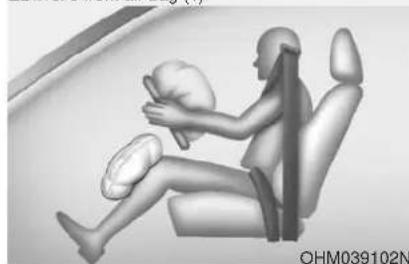
natural_image
3D rendered illustration of a seated person in a chair with hands placed on the back, no text or symbols visibleWhen the SRSCM detects a sufficiently severe impact to the front of the vehicle, it will automatically deploy the front air bags.
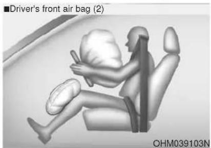
natural_image
3D rendering of a driver's front air bag (2) inside a car seat, showing body and seat positioning (no text or symbols on the diagram itself)Upon deployment, tear seams molded directly into the pad covers will separate under pressure from the expansion of the air bags. Further opening of the covers allows full inflation of the air bags.
A fully inflated air bag, in combination with a properly worn seat belt, slows the driver or the front passenger forward motion, reducing the risk of head and chest injury.
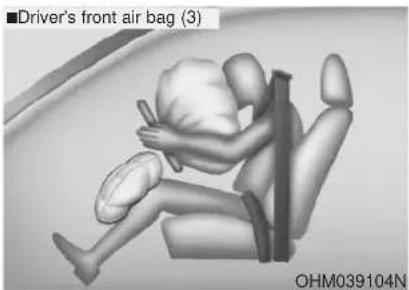
natural_image
3D rendered image of a driver's front air bag (3) in a car seat, showing body and seat positioning (no text or symbols on the diagram itself)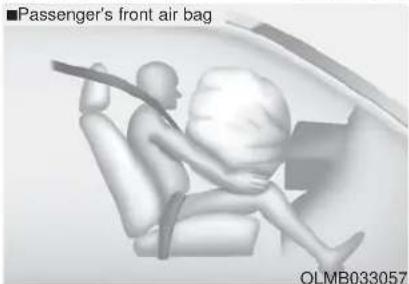
natural_image
3D illustration of a passenger's front air bag inside a car, showing seatbelt and passenger silhouette (no text or symbols on the diagram itself)After complete inflation, the air bag immediately starts deflating, enabling the driver to maintain forward visibility and the ability to steer or operate other controls.
WARNING
To prevent objects from becoming dangerous projectiles when the passenger's air bag inflates:
- Do not install or place any objects (drink holder, CD holder, stickers, etc.) on the front passenger's panel above the glove box where the passenger's air bag is located.
- Do not install a container of liquid air freshener near the instrument cluster or on the instrument panel surface.
What to Expect After an Air Bag Inflates
After a frontal or side air bag inflates, it will deflate very quickly. Air bag inflation will not prevent the driver from seeing out of the windshield or being able to steer. Curtain air bags may remain partially inflated for some time after they deploy.
WARNING
After an air bag inflates, take the following precautions:
- Open your windows and doors as soon as possible after impact to reduce prolonged exposure to the smoke and powder released by the inflating air bag.
- Do not touch the air bag storage area's internal components immediately after an air bag has inflated. The parts that come into contact with an inflating air bag may be very hot.
• Always wash exposed skin areas thoroughly with cold water and mild soap.
• Always have an authorized HYUNDAI dealer replace the air bag immediately after deployment. Air bags are designed to be used only once.
Noise and smoke from inflating air bag
When the air bags inflate, they make a loud noise and may produce smoke and powder in the air inside of the vehicle. This is normal and is a result of the ignition of the air bag inflator. After the air bag inflates, you may feel substantial discomfort in breathing because of the contact of your chest with both the seat belt and the air bag, as well as from breathing the smoke and powder. The powder may aggravate asthma for some people. If you experience breathing problems after an air bag deployment, seek medical attention immediately.
Though the smoke and powder are nontoxic, they may cause irritation to the skin, eyes, nose, throat, etc. If this is the case, wash and rinse with cold water immediately and seek medical attention if the symptoms persist.
Occupant Classification System (OCS)
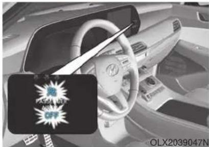
natural_image
Interior view of a car with steering wheel and dashboard, featuring a black promotional tag (no readable text or symbols)Your vehicle is equipped with an Occupant Classification System (OCS) in the front passenger's seat.
Main components of the Occupant Classification System
• A detection device located within the front passenger seat cushion.
• Electronic system to determine whether the passenger air bag systems should be activated or deactivated.
- An indicator light located on the instrument panel which illuminates the words "OFF" and symbol indicating the front passenger air bag system is deactivated.
- The instrument panel air bag indicator light is interconnected with the OCS.
The OCS is designed to help detect the presence of a properly-seated front passenger and determine if the passenger's front air bag should be enabled (may inflate) or not.
The purpose is to help reduce the risk of injury or death from an inflating air bag to certain front passenger seat occupants, such as children, by requiring the air bag to be automatically turned OFF.
For example, if a child restraint of the type specified in the regulations is on the seat, sensor can help detect it and cause the air bag to turn OFF.
Front passenger seat adult occupants who are properly seated and wearing the seat belt properly, should not cause the passenger air bag to be automatically turned OFF. For small adults it may be turned OFF, however, if the occupant does not sit in the seat properly (for example, by not sitting upright, by sitting on the edge of the seat, or by otherwise being out of position), this could cause the sensor to turn the air bag OFF.
You will find the "PASSENGER AIR BAG OFF" indicator on the center fascia panel. This system detects the conditions 1-4 in the following table and activates or deactivates the front passenger air bag based on these conditions.
Always be sure that you and all vehicle occupants are seated properly and wearing the seat belt properly for the most effective protection by the air bag and the seat belt.
The OCS may not function properly if the passenger takes actions which can affect the classification system. These include:
- Failing to sit in an upright position.
- Leaning against the door or center console.
- Sitting towards the sides of the front of the seat.
- Putting their legs on the dashboard or resting them on other locations which reduce the passenger weight on the front seat.
- Wearing the seat belt improperly.
- Reclining the seatback.
- Wearing a thick cloth like ski wear or hip protection wear.
- Putting an additional thick cushion on the seat.
- Putting electrical devices (e.g. notebook, satellite radio) on the seat with inverter charging.
Condition and operation in the front passenger Occupant Classification System
| Condition detected by the occupant classification system | Indicator/Warning light Devices | ||
| "PASSENGER AIR BAG OFF" indicator light | SRS warning light | Front passenger air bag | |
| 1. Adult *1 | Off Off Activated | ||
| 2. Infant *2 or child restraint system with 12 months old *3 *4 | On Off Deactivated | ||
| 3. Unoccupied On Off Deactivated | |||
| 4. Malfunction in the system Off On | Activated | ||
* The system judges a person of adult size as an adult. When a smaller adult sits in the front passenger seat, the system may recognize him/her as a child depending on his/her physique and posture.
* Do not allow children to ride in the front passenger seat. When a larger child who has outgrown a child restraint system sits in the front passenger seat, the system may recognize him/her as an adult depending upon his/her physique or sitting position.
* Never install a child restraint system on the front passenger seat.
* The PASSENGER AIR BAG "OFF" indicator may turn on or off when a child above 12 months to 12 years old (with or without child restraint system) sits in the front passenger seat. This is a normal condition.
WARNING
Riding in an improper position or placing weight on the front passenger's seat when it is unoccupied by a passenger adversely affects the OCS. To reduce the risk of serious injury or death:
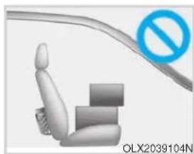
natural_image
3D illustration of a car seat with a blue prohibition symbol (no text or labels on the diagram itself)- NEVER put a heavy load in the front seat or seatback pocket.
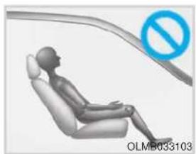
natural_image
3D rendered illustration of a seated human figure in a car seat with a blue prohibition symbol (no text or labels)- NEVER ride with the seat-back reclined when the vehicle is moving.
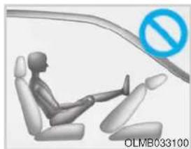
natural_image
3D illustration of a person seated in a car with a blue prohibition symbol (no text or labels on the diagram itself)• NEVER place your feet on the front passenger seat-back.
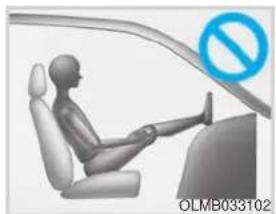
natural_image
3D illustration of a person seated in a car with a blue prohibition symbol (no text or symbols on the diagram itself)- NEVER place your feet or legs on the dashboard.
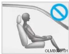
natural_image
3D rendered human figure seated in a car seat with a blue prohibition symbol (no text or symbols on the diagram itself)• NEVER sit with your hips shifted towards the front of the seat.
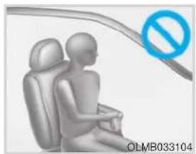
natural_image
Illustration of a person sitting in a car seat with a blue prohibition symbol (no text or symbols on the diagram itself)- NEVER lean on the door or center console or sit on one side of the front passenger seat.
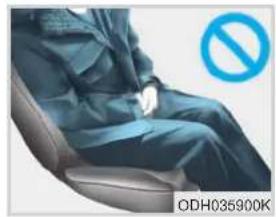
natural_image
Person seated in a chair with a blue prohibition symbol (no text or numbers on the person or chair)- Do not sit on the passenger seat wearing heavily padded clothes such as ski wear and hip protector.
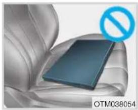
natural_image
Close-up of a car seat with a blue rectangular object and a blue prohibition symbol (no text or symbols on the object itself)- Do not place electronic devices such as laptops, DVD player, or conductive materials such as water bottles on the passenger seat.
- Do not use electronic devices such as laptops and satellite radios which use inverter chargers.
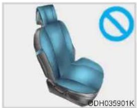
natural_image
Blue and gray car seat with a blue prohibition symbol (no text or labels on the seat itself)- Do not use car seat accessories such as thick blankets and cushions which cover up the car seat surface.
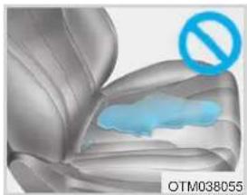
natural_image
3D rendered image of a car seat with a blue shaded area and a blue prohibition symbol (no text or labels)- If large quantity of liquid has been spilled on the passenger seat, the air bag warning light may illuminate or malfunction. Therefore, make sure the seat has been completely dried before driving the vehicle.
- Do not place sharp objects on the front passenger seat. These may damage the occupant detection system, if they puncture the seat cushion.
- Do not place any items under the front passenger seat.
- When changing or replacing the seat or seat cover, use original items only. The OCS has been developed based on using original HYUNDAI car seats only. Altering or changing the authentic parts may result in system malfunction and increase risk of injury when in collision. Any of the above could interfere with the proper operation of the OCS sensor thereby increasing the risk of an injury in an accident.
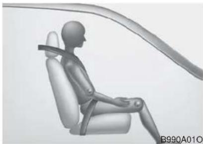
natural_image
3D rendered human figure seated in a car seat, viewed from above (no text or symbols)Proper seated position for OCS If the "PASSENGER AIR BAG OFF" indicator is on when an adult is seated in the front passenger seat, place the Engine Start/Stop button in the OFF position and ask the passenger to sit properly (sitting upright with the seat back in an upright position, centered on the seat cushion with their seat belt on, legs comfortably extended and their feet on the floor). Restart the engine and have the person remain in that position. This will allow the system to detect the person and to enable the passenger air bag. If the "PASSENGER AIR BAG OFF" indicator is still on, ask the passenger to move to the rear seat.
WARNING
Never allow an adult passenger to ride in the front passenger seat when the "PASSENGER AIR BAG OFF" indicator is illuminated. During a collision, the air bag will not inflate if the indicator is illuminated. Have your passenger reposition themself in the seat. If the "PASSENGER AIR BAG OFF" indicator remains illuminated after the passenger repositions themselves properly and the vehicle is restarted, have the passenger move to the rear seat because the air bag will not inflate.
NOTICE
The "PASSENGER AIR BAG OFF" indicator illuminates for approximately 4 seconds after the Engine Start/Stop button is in the ON position or after the engine is started. If the front passenger seat is occupied, the OCS will then classify the front passenger after several more seconds.
Do Not Install a Child Restraint in the Front Passenger's Seat
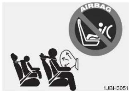
Even though your vehicle is equipped with the OCS, never install a child restraint in the front passenger's seat. An inflating air bag can forcefully strike a child or child restraint resulting in serious or fatal injury.
WARNING
- NEVER place a rear-facing or front-facing child restraint in the front passenger's seat of the vehicle.
- An inflating frontal air bag could forcefully strike a child resulting in serious injury or death.
• Always properly restrain children in an appropriate child restraint in the rear seat of the vehicle.
Why Didn't My Air Bag Go Off in a Collision?
Air bags are not designed to inflate in every collision. There are certain types of accidents in which the air bag would not be expected to provide additional protection. These include rear impacts, second or third collisions in multiple impact accidents, as well as low speed impacts. Damage to the vehicle indicates a collision energy absorption, and is not an indicator of whether or not an air bag should have inflated.
Air bag collision sensors
WARNING
To reduce the risk of an air bag deploying unexpectedly and causing serious injury or death:
- Do not hit or allow any objects to impact the locations where air bags or sensors are installed.
- Do not perform maintenance on or around the air bag sensors. If the location or angle of the sensors is altered, the air bags may deploy when they should not or may not deploy when they should.
- Do not install bumper guards or replace the bumper with a non-genuine HYUNDAI parts. This may adversely affect the collision and air bag deployment performance.
- Place the ignition switch in the LOCK/OFF or ACC position when the vehicle is being towed to prevent inadvertent air bag deployment.
- Have all air bag repairs conducted by an authorized HYUNDAI dealer.
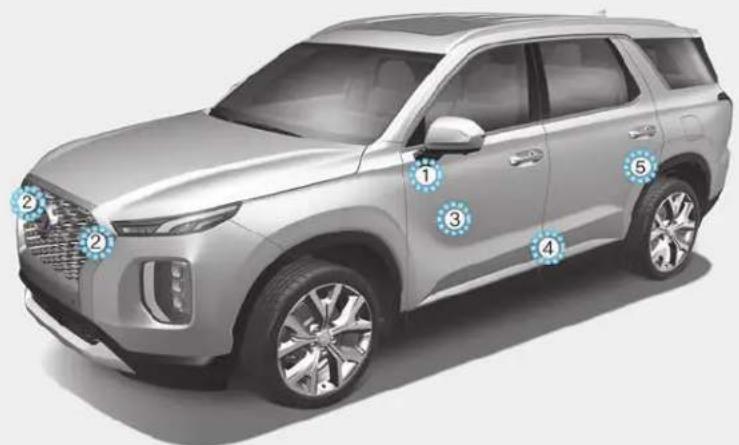
- SRS control module/Rollover sensor
- Front impact sensor
- Side pressure sensor
- Side impact sensor
- Side impact sensor
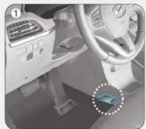
natural_image
Interior view of a car dashboard and steering wheel (no visible text or symbols)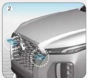
natural_image
Close-up of a car's front grille and headlights (no visible text or symbols)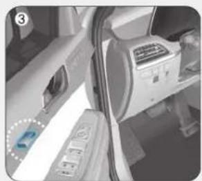
natural_image
Interior view of a car showing the door, air conditioner unit, and dashboard (no visible text or symbols)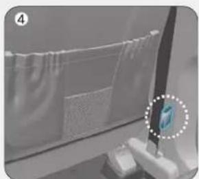
natural_image
Close-up of a window with fabric panels and a small electronic device on the right (no visible text or symbols)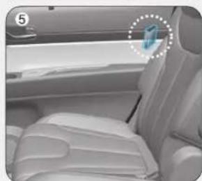
natural_image
Interior view of a car backseat and seat area, showing white leather seats and a small blue icon on the side (no text or symbols visible)OLX2039052N/OLX2038053N/OLX2039054N/OLX2038055N/OLX2038056/OLX2038057
Air bag inflation conditions
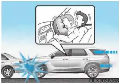
Front air bags
Front air bags and the driver's knee air bag are designed to inflate in a frontal collision depending on the severity of impact of the front collision.
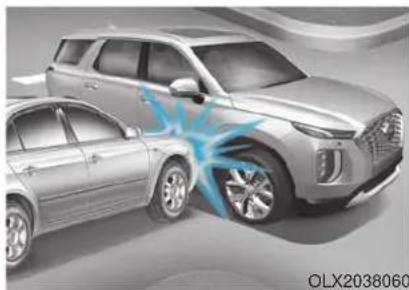
natural_image
Illustration of two cars with a blue light effect on the side, no visible text or symbols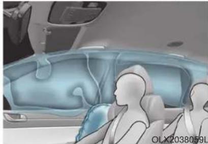
natural_image
Interior view of a car with two seated individuals, one inside and one in the back seat, showing no visible text or symbols.Side and curtain air bags
Side and curtain air bags are designed to inflate when an impact is detected by side collision sensors depending on the severity of impact resulting from a side impact collision.
Although the driver's and front passenger's air bags are designed to inflate only in frontal collisions, they also may inflate in other types of collisions if the front impact sensors detect a sufficient impact. Side and curtain air bags are designed to inflate only in side impact collisions or rollover situations, but they may inflate in other collisions if the side impact sensors detect a sufficient impact.
If the vehicle chassis is impacted by bumps or objects on unimproved roads, the air bags may deploy. Drive carefully on unimproved roads or on surfaces not designed for vehicle traffic to prevent unintended air bag deployment.
Air bag non-inflation conditions
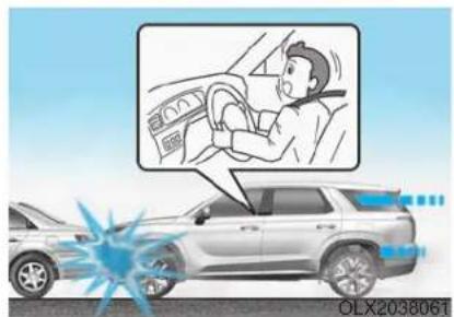
In certain low-speed collisions the air bags may not deploy. The air bags are designed not to deploy in such cases because they may not provide benefits beyond the protection of the seat belts.
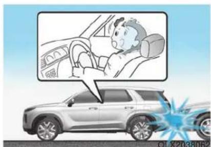
natural_image
Illustration of a car with a driver inside the dashboard and a blue explosion effect near the front (no text or symbols)Front air bags are not designed to inflate in rear collisions, because occupants are moved backward by the force of the impact. In this case, inflated air bags would not provide any additional benefit.
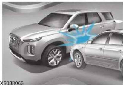
natural_image
Exterior view of two modern SUVs (no visible text or symbols)OLX2038063
Front air bags may not inflate in side impact collisions, because occupants move in the direction of the collision, and thus in side impacts, front air bag deployment would not provide additional occupant protection.
However, side and curtain air bags may inflate depending on the severity of impact.
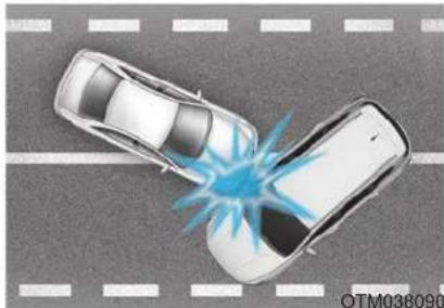
natural_image
Top-down illustration of two cars on a road with a blue explosion effect (no text or symbols)In an angled collision, the force of impact may direct the occupants in a direction where the air bags would not be able to provide any additional benefit, and thus the sensors may not deploy any air bags.
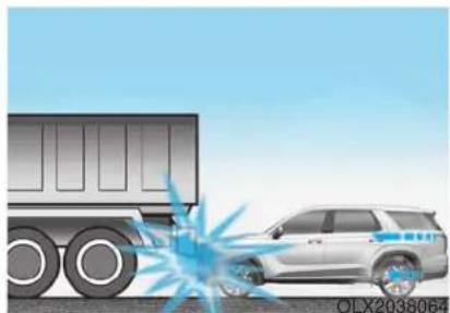
natural_image
Illustration of a truck and a car with impact effect, no text or symbols presentJust before impact, drivers often brake heavily. Such heavy braking lowers the front portion of the vehicle causing it to "ride" under a vehicle with a higher ground clearance. Air bags may not inflate in this "underride" situation because deceleration forces that are detected by sensors may be significantly reduced by such "underride" collisions.
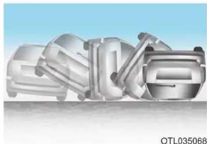
natural_image
3D rendered mechanical components with metallic surfaces, no visible text or symbolsFront air bags may not inflate in rollover accidents because air bag deployment could not provide protection to the occupants.
However, side and curtain air bags may inflate when the vehicle is rolled over by a side impact collision.
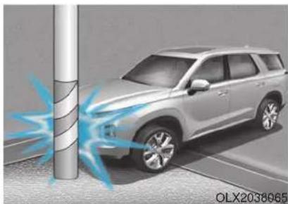
natural_image
Illustration of a silver SUV parked near a vertical pole with blue light effects, no text or symbols present.Air bags may not inflate if the vehicle collides with objects such as utility poles or trees, where the point of impact is concentrated and the collision energy is absorbed by the vehicle structure.
SRS Care
The SRS is virtually maintenance-free and there are no parts you can safely service by yourself. If the SRS air bag warning light does not illuminate when the ignition switch is in the ON position, or continuously remains on, have your vehicle immediately inspected by an authorized HYUNDAI dealer.
Any work on the SRS system, such as removing, installing, repairing, or any work on the steering wheel, the front passenger's panel, front seats and roof rails must be performed by an authorized HYUNDAI dealer. Improper handling of the SRS system may result in serious personal injury.
WARNING
To reduce the risk of serious injury or death, take the following precautions:
- Do not attempt to modify or disconnect the SRS components or wiring, including the addition of any kind of badges to the pad covers or modifications to the body structure.
- Do not place objects over or near the air bag modules on the steering wheel, instrument panel, or the front passenger's panel above the glove box.
- Clean the air bag pad covers with a soft cloth moistened with plain water. Solvents or cleaners could adversely affect the air bag covers and proper deployment of the system.
• Always have inflated air bags replaced by an authorized HYUNDAI dealer.
- If components of the air bag system must be discarded, or if the vehicle must be scrapped, certain safety precautions must be observed. Consult an authorized HYUNDAI dealer for the necessary information. Failure to follow these precautions could increase the risk of personal injury.
Additional Safety Precautions
Passengers should not move out of or change seats while the vehicle is moving. A passenger who is not wearing a seat belt during a crash or emergency stop can be thrown against the inside of the vehicle, against other occupants, or be ejected from the vehicle.
Do not use any accessories on seat belts. Devices claiming to improve occupant comfort or reposition the seat belt can reduce the protection provided by the seat belt and increase the chance of serious injury in a crash.
Do not modify the front seats.
Modification of the front seats could interfere with the operation of the supplemental restraint system sensing components or side air bags.
Do not place items under the front seats. Placing items under the front seats could interfere with the operation of the supplemental restraint system sensing components and wiring harnesses.
Do not cause impact to the doors. Impact to the doors when the Engine Start/Stop button is in the ON position may cause the air bags to inflate.
Modifications to accommodate disabilities. If you require modification to your vehicle to accommodate a disability, contact the HYUNDAI Customer Connect Center at 800-633-5151.
Adding equipment to or modifying your air bag equipped vehicle
If you modify your vehicle by changing your vehicle's frame, bumper system, front end or side sheet metal or ride height, this may affect the operation of your vehicle's air bag system.
Air Bag Warning Labels
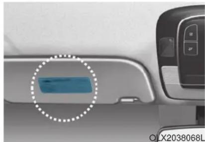
natural_image
Close-up of a car interior panel with a highlighted blue rectangular object, no visible text or symbolsAir bag warning labels, required by the U.S. National Highway Traffic Safety Administration (NHTSA), are attached to alert the driver and passengers of potential risks of the air bag system. Be sure to read all of the information about the air bags that are installed on your vehicle in this Owners Manual.
Convenient features of your vehicle
Accessing your vehicle 3-4
Remote Key....3-4
Smart Key....3-8
Immobilizer System....3-14
Door locks....3-15
Operating Door Locks from Outside the Vehicle....3-15
Operating Door Locks from Inside the Vehicle.....3-16
Automatic Door Lock and Unlock Features ....3-19
Child-Protector Rear Door Locks....3-20
Electronic Child Safety Lock System ....3-20
Safe Exit Assist (SEA) System....3-21
Rear Occupant Alert (ROA) System 3-23
Theft-alarm system....3-26
Driver position memory system....3-27
Storing Positions into Memory....3-27
Recalling Positions from Memory....3-28
Resetting the Driver's Seat Memory System......3-28
Easy Access Function 3-29
Steering wheel....3-30
Electric Power Steering (EPS) 3-30
Tilt Steering / Telescopic Steering....3-31
Horn....3-31
Heated Steering Wheel....3-32
Mirrors....3-33
Inside Rearview Mirror 3-33
Side View Mirrors 3-39
Reverse Parking Aid Function....3-41
Windows 3-42
Power Windows....3-43
Sunroof....3-46
Sunroof....3-46
Dual wide sunroof....3-46
Sunshade....3-47
Sunroof Opening and Closing....3-48
Sliding the Sunroof....3-48
Tilting the Sunroof (Front)....3-49
Resetting the Sunroof 3-50
Resetting the rear sunshade....3-51
Sunroof Open Warning....3-52
Exterior features 3-53
Hood 3-53
Non-Powered Liftgate....3-54
Power Liftgate 3-56
Smart Liftgate....3-62
Fuel Filler Door....3-66
Instrument cluster....3-69
Instrument Cluster Control....3-71
Gauges and Meters 3-71
Transmission Shift Indicator....3-76
Warning and Indicator Lights....3-76
LCD Display Messages....3-90
LCD Display (Cluster type A and type B)......3-96
LCD Display Control....3-96
LCD Display Modes....3-97
TRIP Computer (Cluster type A and type B) ..3-110
LCD Display (Cluster type C)....3-114
LCD Display Control....3-114
View Modes....3-115
Option Menu (Cluster type C)....3-119
Head up display (HUD)....3-130
Lighting....3-132
Exterior Lights 3-132
Interior Lights 3-139
Welcome System....3-142
Wipers and washers 3-144
Front Windshield Wipers....3-144
Front Windshield Washers....3-146
Rear Window Wiper and Washer....3-147
Driver Assist System 3-148
Rear View Monitor 3-148
Surround View Monitoring 3-149
Blind-spot View Monitor system....3-150
Parking Distance Warning (Reverse) System .....3-152
Parking Distance Warning(Reverse/Forward)
System 3-155
Manual climate control system....3-159
Heating and Air Conditioning....3-160
Rear climate control....3-164
System Operation 3-167
System Maintenance....3-169
Automatic climate control system....3-171
Automatic Temperature Control Mode....3-172
Manual Temperature Control Mode....3-173
Rear climate control....3-179
System Operation 3-182
System Maintenance....3-184
Convenient features of your vehicle
Windshield defrosting and defogging .....3-186
Auto Defogging System (Additional Feature with
Automatic Temperature Control System)....3-188
Rear Window Defroster 3-190
Climate control additional features......3-191
Cluster ionizer....3-191
Automatic Ventilation....3-191
Sunroof Inside Air Recirculation....3-191
Storage compartment....3-192
Center Console Storage 3-192
Glove Box....3-192
Luggage Tray 3-193
Interior features....3-194
Cup Holder 3-194
Conversation mirror....3-196
Sunvisor....3-196
Power Outlet 3-197
AC Inverter....3-198
USB Charger....3-200
Wireless Cellular Phone Charging System......3-201
Clock....3-203
Coat Hook 3-203
Floor Mat Anchor(s)....3-204
Luggage Net Holder 3-205
Cargo Security Screen....3-205
Side Curtain 3-207
Exterior features 3-209
Roof Side Rails 3-209
ACCESSING YOUR VEHICLE Remote Key (if equipped)
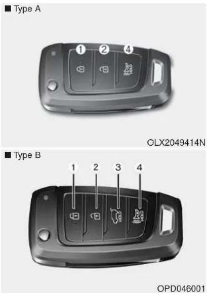
Your HYUNDAI uses a remote key, which you can use to lock or unlock the driver and passenger doors or the rear liftgate.
- Door Lock
- Door Unlock
- Liftgate Unlock (if equipped)
- Panic
Locking your vehicle
To lock your vehicle:
- Make sure all doors, the engine, hood and the liftgate are closed.
- Press the Door Lock button (1) on the remote key to lock all doors.
- If the Door Lock button (1) is pressed once more within four seconds, the horn will beep once and the hazard warning lights will blink.
- Make sure the doors are locked by checking the position of the door lock button inside the vehicle.
WARNING
Do not leave the keys in your vehicle with unsupervised children. Unattended children could place the key in the ignition switch and may operate power windows or other controls, or even make the vehicle move, which could result in serious injury or death.
Unlocking your vehicle
To unlock your vehicle :
-
Press the Door Unlock button (2) on the remote key.
-
The driver's door will unlock. The hazard warning lights will blink two times.
Two Press Unlock Feature
The priority for unlocking the driver door only, or unlocking all the doors with one press may be adjusted in the User Settings mode in the cluster LCD display.
The Two Press Unlock feature, when enabled, will require the user to press the door unlock button once for driver door only and twice for unlocking all the doors.
Select or Deselect the Two Press Unlock feature in the User Settings mode in the cluster LCD display. The option can be found under the following menu:
User Settings → Door → Two Press Unlock
The Two Press Unlock feature can also be enabled or disabled by pressing the door lock and unlock buttons simultaneously on the Key FOB:
Press and hold both the Door Lock button and the Door Unlock button simultaneously until the hazard warning lights blink.
This will enable or disable the Two Press Unlock feature. Repeat this procedure to enable/disable the mode again.
i Information
After unlocking the doors, the doors will automatically relock after 30 seconds unless a door is opened.
Liftgate unlocking (if equipped)
To unlock the liftgate :
- Press and hold the Liftgate Unlock button (3) on the remote key for more than one second.
- The hazard warning lights will blink two times and the liftgate will open.
- Once the liftgate is opened and then closed, the liftgate will automatically re-lock after 30 seconds.
i Information
The word "HOLD" is written on the button to inform you that you must press and hold the button for more than one second.
Panic button
Press and hold the Panic button (4) for more than one second. The horn sounds and hazard warning lights flash for about 30 seconds.
To cancel the panic mode, press any button on the remote key.
Start-up
For information, refer to the "Key Ignition Switch" section in chapter 5.
NOTICE
To prevent damaging the remote key:
- Keep the remote key away from water or any liquid and fire. Internal circuits may malfunction if the inside of the remote key gets damp (from liquids or moisture) or if it is heated. This can exclude the remote key from being covered under warranty.
- Avoid dropping or throwing the remote key.
- Protect the remote key from extreme temperatures.
Mechanical key
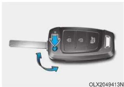
natural_image
Close-up of a car key with a blue arrow indicating rotation and change, no visible text or symbols on the main object.If the remote key does not operate normally, you can lock or unlock the driver's door by using the mechanical key.
To unfold the mechanical key, press the release button on the remote key. To return the key to its stored position, press the release button and fold the key back into the remote key.
Remote key precautions
The remote key will not work if any of the following occur:
• The key is in the ignition switch.
- You exceed the operating distance limit (about 90 feet [30 m]).
• The remote key battery is weak.
- Other vehicles or objects may be blocking the signal.
• The weather is extremely cold.
- The remote key is close to a radio transmitter such as a radio station or an airport which can interfere with normal operation of the remote key.
If the remote key does not work correctly, open and close the door with the mechanical key. If you have a problem with the remote key contact an authorized HYUNDAI dealer.
If the remote key is in close proximity to your mobile phone, the signal could be blocked by your mobile phone's normal operational signals. This is specifically relevant when the phone is active such as making and receiving calls, text messaging, and/or sending/receiving emails.
When possible, avoid placing the remote key and your mobile phone in the same location such as a pants or jacket pocket in order to avoid interference between the two devices.

Information
This device complies with Part 15 of the FCC rules.
Operation is subject to the following three conditions:
- This device may not cause harmful interference.
- This device must accept any interference received, including interference that may cause undesired operation.
- Changes or modifications not expressly approved by the party responsible for compliance could void the user's authority to operate the device.
NOTICE
Keep the remote key away from electromagnetic materials that block electromagnetic waves to the key surface.
Battery replacement
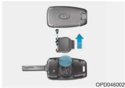
natural_image
Diagram of a car key being inserted into a closed door, showing internal components and a blue arrow indicating motion (no text or symbols)If the remote key is not working properly, try replacing the battery with a new one.
Battery Type: CR2032
To replace the battery:
- Insert a slim tool into the slot and gently pry open the cover.
- Using a screw driver, remove the battery cover.
- Remove the old battery and insert the new battery. Make sure the battery position is correct.
- Reinstall the battery cover and key cover in the reverse order of removal.
If you suspect your remote key might have sustained some damage, or you feel your remote key is not working correctly contact an authorized HYUNDAI dealer.

Information

An inappropriately disposed battery can be harmful to the environment and human health. Dispose of the battery according to your local law(s) or regulations.
Smart Key (if equipped)
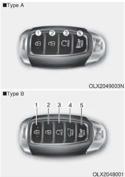
Your HYUNDAI uses a Smart Key, which you can use to lock or unlock the driver and passenger doors or the rear liftgate.
- Door Lock
- Door Unlock
- Remote start
- Liftgate Unlock (if equipped)
- Panic
Locking your vehicle
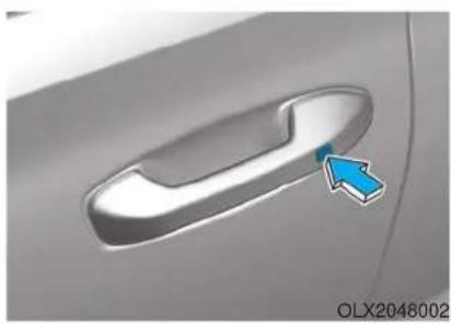
natural_image
Close-up of a car door handle with a blue arrow pointing to the handle area (no text or symbols visible)To lock your vehicle using the door handle button or the Smart Key:
- Make sure all doors, the hood and the liftgate are closed.
-
Make sure you have the smart key in your possession.
-
Press either the button on the door handle or the Door Lock button (1) on the smart key. The chime will sound once and the hazard warning lights will blink.
- Make sure the doors are locked by checking the position of the door lock button inside the vehicle.
i Information
The door handle button will only operate when the smart key is within 28\~40 inches (0.7\~1 m) from the outside door handle.
Note that you cannot lock your vehicle using the door handle button if any of the following occur:
• The Smart Key is in the vehicle.
- The Engine Start/Stop button is in ACC or ON position.
- Any of the doors are open except for the liftgate.
WARNING
Do not leave the Smart Key in your vehicle with unsupervised children. Unattended children could press the Engine Start/Stop button and may operate power windows or other controls, or even make the vehicle move, which could result in serious injury or death.
Unlocking your vehicle
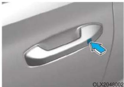
natural_image
Close-up of a car door handle with a blue arrow pointing to the left side (no text or symbols on the door itself)To unlock your vehicle:
-
Make sure you have the smart key in your possession.
-
Press either the button on the door handle or the Door Unlock button (2) on the smart key. The driver's door will unlock and the hazard warning lights will blink two times.
Two Press Unlock Feature
The priority for unlocking the driver door only, or unlocking all the doors with one press may be adjusted in the User Settings mode in the cluster LCD display.
The Two Press Unlock feature, when enabled, will require the user to press the door unlock button once for driver door only and twice for unlocking all the doors.
Select or Deselect the Two Press Unlock feature in the User Settings mode in the cluster LCD display. The option can be found under the following menu:
User Settings → Door → Two Press Unlock
The Two Press Unlock feature can also be enabled or disabled by pressing the door lock and unlock buttons simultaneously on the Key FOB:
Press and hold both the Door Lock button and the Door Unlock button simultaneously until the hazard warning lights blink.
This will enable or disable the Two Press Unlock feature. Repeat this procedure to enable/disable the mode again.
i Information
- The door handle buttons will only operate when the smart key is within 28-40 inches (0.7\~1m) from the outside door handle.
- Either the driver or front passenger door can be opened with the door handle button when the smart key is within this range.
- If you press the front passenger outside door handle with the smart key in your possession, all the doors will unlock.
Remote start (if equipped)
You can start the vehicle using the remote start button (4) of the smart key.
To start the vehicle remotely :
- Lock the doors by pressing the door lock button (1) within 32 ft (10 m) distance from the vehicle.
- Press the remote start button for over 2 seconds within 4 seconds after locking the doors.
Press the remote start button once to turn off the vehicle.
Air conditioner/heater system maintains the status before turning off the vehicle.
If no further action for operating/driving the vehicle is taken, the vehicle will be turned off 10 minutes after starting the vehicle remotely.
CAUTION
- Laws in your country may restrict the use of remote start. You should check country regulations before using this remote starting system.
- It is only possible to start the vehicle remotely when shifted to P (Park).
- If the hood or the liftgate is opened, you cannot start the vehicle remotely.
- The Remote start function works the same as Blue Link remote start. For further caution information, refer to the separately supplied "Blue Link (Infotainment system) manual".
Opening the liftgate
Non-power liftgate
To unlock and open the liftgate:
-
Make sure you have the smart key in your possession.
-
Press either the liftgate handle release switch on the vehicle for more than one second. The hazard warning lights will blink two times and the liftgate latch will unlock.
-
Once the liftgate is opened and then closed, the liftgate will automatically re-lock after 30 seconds.
i Information
The liftgate handle switch will only operate when the smart key is within 28 inches (0.7 m) from the liftgate handle.
Power liftgate
To unlock and open the liftgate:
-
Make sure you have the smart key in your possession.
-
Press either the liftgate handle release switch on the vehicle or press and hold the Liftgate Unlock button (4) on the smart key for more than one second. The hazard warning lights will blink two times and the liftgate latch will open.
-
Once the liftgate is opened and then closed, the liftgate will automatically re-lock after 30 seconds.
i Information
The liftgate handle switch will only operate when the smart key is within 28 inches (0.7 m) from the liftgate handle.
Panic button
Press and hold the Panic button (5) for more than one second. The horn sounds and hazard warning lights blink for about 30 seconds. To cancel the panic mode, press any button on the Smart Key.
Start-up
You can start the vehicle without inserting the key.
For information, refer to the "Engine Start/Stop Button" section in chapter 5.
NOTICE
To prevent damaging the smart key:
- Keep the smart key in a cool, dry place to avoid damage or malfunction. Exposure to moisture or high temperature may cause the internal circuit of the smart key to malfunction which may not be covered under warranty.
- Avoid dropping or throwing the smart key.
- Protect the smart key from extreme temperatures.
Mechanical key
If the Smart Key does not operate normally, you can lock or unlock the driver's door by using the mechanical key.
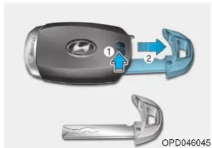
natural_image
Close-up of a car key with two open buttons and a handle, showing internal components (no text or symbols)To remove the mechanical key from the smart key FOB, slide the release lever in the direction of the arrow (1) and then pull the mechanical key (2) outward.
To unlock the vehicle using the mechanical key, insert the mechanical key into the key hole in the driver door (Refer to page 3-15).
To reinstall the mechanical key into the FOB, insert the key in the top of the key FOB and push inward until a click sound is heard.
Loss of a smart key
A maximum of two Smart Keys can be registered to a single vehicle. If you happen to lose your smart key, you should immediately take the vehicle and remaining keys to your authorized HYUNDAI dealer or tow the vehicle, if necessary.
Smart key precautions
The smart key may not work if any of the following occur:
- The smart key is close to a radio transmitter such as a radio station or an airport which can interfere with normal operation of the transmitter.
- The smart key is near a mobile two way radio system or a cellular phone.
- Another vehicle's smart key is being operated close to your vehicle.
If the smart key does not work cor-
rectly, open and close the door with the mechanical key. If you have a problem with the smart key, contact an authorized HYUNDAI dealer.
If the smart key is in close proximity to your mobile phone, the signal could be blocked by your mobile phone's normal operational signals. This is specifically relevant when the phone is active such as making and receiving calls, text messaging, and/or sending/receiving emails. When possible, avoid keeping the remote key and your mobile phone in the same location such as a pants or jacket pocket in order to avoid interference between the two devices.
NOTICE
Keep the smart key away from electromagnetic materials that blocks electromagnetic waves to the key surface.
NOTICE
Always have the smart key with you when leaving the vehicle. If the smart key is left near the vehicle, the vehicle battery may be discharged.
i Information
This device complies with Part 15 of the FCC rules.
Operation is subject to the following three conditions:
-
This device may not cause harmful interference.
-
This device must accept any interference received, including interference that may cause undesired operation.
-
Changes or modifications not expressly approved by the party responsible for compliance could void the user's authority to operate the device.
Battery replacement
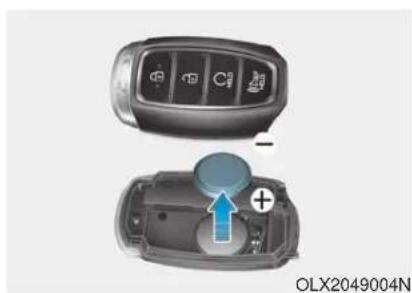
natural_image
Interior view of a car showing the front and rear views of a vehicle's dashboard with a highlighted central component (no text or symbols visible)If the Smart Key is not working properly, try replacing the battery with a new one.
Battery Type: CR2032
To replace the battery:
- Remove the mechanical key.
- Use a slim tool to pry open the rear cover of the smart key.
- Remove the old battery and insert the new battery. Make sure the battery position is correct.
- Reinstall the rear cover of the smart key.
If you suspect your smart key might have sustained some damage, or you feel your smart key is not working correctly, contact an authorized HYUNDAI dealer.
i Information

An inappropriately disposed battery can be harmful to the environment and human health. Dispose of the battery according to your local law(s) or regulations.
Immobilizer System (if equipped)
The immobilizer system protects your vehicle from theft. If an improperly coded key (or other device) is used, the engine's fuel system is disabled.
When the ignition switch is placed in the ON position, the immobilizer system indicator should come on briefly, then go off. If the indicator starts to blink, the system does not recognize the coding of the key.
Turn the ignition switch to the LOCK/OFF position, then turn the ignition switch to the ON position again.
In some circumstances, the vehicle may not recognize your remote key or smart key if another remote key or smart key device is nearby or a metal object such as a key chain is causing interference with the remote key or smart key.
If this occurs, your vehicle may not start. Remove any metal objects or additional keys near the remote key or smart key before attempting to start the vehicle again.
If the system repeatedly does not recognize the coding of the key, it is recommended that you contact your HYUNDAI dealer.
Do not attempt to alter this system or add other devices to it. Electrical problems could result that may make your vehicle inoperable.
WARNING
In order to prevent theft of your vehicle, do not leave spare keys anywhere in your vehicle. Your immobilizer password is a customer unique password and should be kept confidential.
NOTICE
The transponder in your key is an important part of the immobilizer system. It is designed to give years of trouble-free service, however you should avoid exposure to moisture, static electricity and rough handling. Immobilizer system malfunction could occur.
i Information
This device complies with Part 15 of the FCC rules.
Operation is subject to the following three conditions:
-
This device may not cause harmful interference.
-
This device must accept any interference received, including interference that may cause undesired operation.
-
Changes or modifications not expressly approved by the party responsible for compliance could void the user's authority to operate the device.
DOOR LOCKS
Operating Door Locks from Outside the Vehicle
Mechanical key
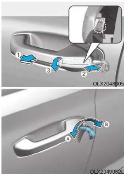
First, pull the outside door handle (1) and push the hook (2) located inside of outside door handle by using the mechanical key. And remove the cover (3) and lower the cover downward not to be damaged.
NOTICE
Be careful not to damage the cover while removing it or misplace it after removing it.
After removing the cover, turn the key toward the front of the vehicle to unlock and toward the rear of the vehicle to lock.
If you lock the driver's door with a mechanical key, the driver's door will lock. If you unlock the driver's door with a mechanical key, you can open and close the driver's door only.
Once the doors are unlocked, they may be opened by pulling the door handle. When closing the door, push the door by hand. Make sure that doors are closed securely.
Remote key
natural_image
Close-up of a car's front panel with two buttons labeled 1 and 2, showing blue navigation icons (no readable text or symbols beyond labels)To lock the doors, press the Door Lock button (1) on the remote key.
Press the Door Unlock button (2) on the remote key, the driver's door will unlock. If you press the Door Unlock button on the remote key again within four seconds, then all the doors will unlock.
Once the doors are unlocked, they may be opened by pulling the door handle. When closing the door, push the door by hand. Make sure that doors are closed securely.
Smart key
Press the button on the driver's outside door handle while carrying the Smart Key with you or press the Door Unlock button on the Smart Key, the driver's door will unlock.
If you press the button on the front passenger's outside door, all doors will unlock.
Once the doors are unlocked, they may be opened by pulling the door handle.
When closing the door, push the door by hand. Make sure that doors are closed securely.
i Information
• In cold and wet climates, door lock and door mechanisms may not work properly due to freezing conditions.
- If the door is locked/unlocked multiple times in rapid succession with either the vehicle key or door lock switch, the system may stop operating temporarily in order to protect the circuit and prevent damage to system components.
- Two press unlock setting can be changed in the User Settings mode on the cluster.
Operating Door Locks from Inside the Vehicle
With the door lock button
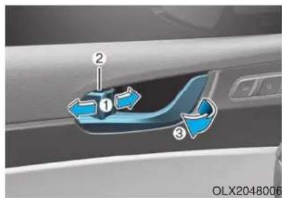
- To unlock a door, push the door lock button (1) to the "Unlock" position. The red mark (2) on the door lock button will be visible.
-
To lock a door, push the door lock button (1) to the "Lock" position. If the door is locked properly, the red mark (2) on the door lock button will not be visible.
• To open a door, pull the door handle (3) outward. -
If the inner door handle of either the driver door or passenger door is pulled when the door lock button is in the lock position, the button is unlocked and the door will open.
- For Key Start Vehicles (with Remote Key)
The front doors cannot be locked if the remote key is in the ignition switch and either of the front doors are open.
- For Push Button Start Vehicles (with Smart Key)
The doors cannot be locked if the smart key is inside the vehicle and any of the doors are open.
i Information
If a power door lock ever fails to function while you are in the vehicle try one or more of the following techniques to exit:
- Operate the door unlock feature repeatedly (both electronic and manual) while simultaneously pulling on the door handle.
- Operate the other door locks and handles, front and rear.
- Lower a front window and use the mechanical key to unlock the door from outside.
i Information
When the vehicle's battery run out and you leave the vehicle, make sure all the doors are locked. You can lock the driver's door with a key and the rest of the doors with the lock button above the door inside handle.
With the central door lock switch
■Driver's door ■Passenger's door
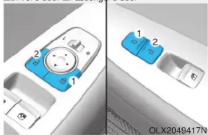
natural_image
Diagram of a car interior showing two blue plastic compartments labeled 1 and 2, with no visible text or symbols.The driver side and front passenger side door armrest is equipped with a central door lock switch. The lock button is indicated by a ( ) symbol.
The unlock button is indicated by a ( Symbol.
When the lock button (1) is pressed, all the vehicle doors will lock.
When the unlock button (2) is pressed, all the vehicle doors will unlock.
- For Key Start Vehicles (with Remote Key)
If the key is in the ignition switch and any door is opened, the doors will not lock even though the lock button (2) is pressed.
- For Push Button Start Vehicles (with Smart Key)
If the smart key is in the vehicle and any door is open, the doors will not lock even though the lock button (2) is pressed.
WARNING
- The doors should always be fully closed and locked while the vehicle is in motion. If the doors are unlocked, the risk of being thrown from the vehicle in a crash is increased.
- Do not pull the inner door handle of the driver's or passenger's door while the vehicle is moving.
WARNING
Do not leave children or animals unattended in your vehicle. An enclosed vehicle can become extremely hot, causing death or serious injury to unattended children or animals who cannot escape the vehicle. Children might operate features of the vehicle that could injure them, or they could encounter other harm, possibly from someone gaining entry to the vehicle.
WARNING
Always secure your vehicle.
Leaving your vehicle unlocked increases the potential risk to you or others from someone hiding in your vehicle.
To secure your vehicle, while depressing the brake, press the P (Park) button, engage the parking brake, and place the ignition switch in the LOCK/OFF position, close all windows, lock all doors, and always take the key with you.
CAUTION
Opening a door when something is approaching may cause damage or injury. Be careful when opening doors and watch for vehicles, motorcycles, bicycles or pedestrians approaching the vehicle in the path of the door.
WARNING
If you stay in the vehicle for a long time while the weather is very hot or cold, there are risks of injuries or danger to life. Do not lock the vehicle from the outside when someone is in the vehicle.
Automatic Door Lock and Unlock Features
Your vehicle is equipped with features that will automatically lock or unlock your vehicle based on settings you select in the cluster LCD display.
Auto LOCK - Enable on Speed
When this feature is set in the cluster LCD display, all the doors will be locked automatically when the vehicle exceeds 9 mph (15 kph).
Auto LOCK - Enable on Shift
When this feature is set in the cluster LCD display, all the doors will be locked automatically when the vehicle is shifted out of P (Park) while the engine is running.
Auto UNLOCK - On shift to P
When this feature is set in the LCD cluster display, all the doors will be unlocked automatically when the vehicle is shifted back into P (Park).
Auto UNLOCK - On key out (if equipped with remote key)
When this feature is set in the LCD cluster display, all the doors will be unlocked automatically when the ignition key is removed from the key ignition switch.
Auto UNLOCK - Vehicle Off (if equipped with smart key)
When this feature is set in the LCD cluster display, all the doors will be unlocked automatically when the vehicle is off.
For more information on these features, refer to the LCD Display section later in this chapter.
Additional Unlock Safety Feature - Air Bag Deployment
As an additional safety feature, all doors will be automatically unlocked when an impact causes the air bags to deploy.
Child-Protector Rear Door Locks (if equipped)
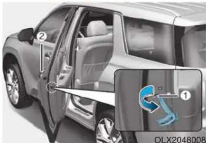
To allow a rear door to be opened from inside the vehicle, unlock the child safety lock.
WARNING
If children accidentally open the rear doors while the vehicle is in motion, they could fall out of the vehicle. The rear door safety locks should always be used whenever children are in the vehicle.
The child safety lock is provided to help prevent children seated in the rear from accidentally opening the rear doors. The rear door safety locks should be used whenever children are in the vehicle.
The child safety lock is located on the edge of each rear door. When the child safety lock is in the lock position, the rear door will not open if the inner door handle is pulled.
To lock the child safety lock, insert a small flat blade tool (like a screwdriver or similar) (1) into the slot and turn it to the lock position as shown.
Electronic Child Safety Lock System (if equipped)
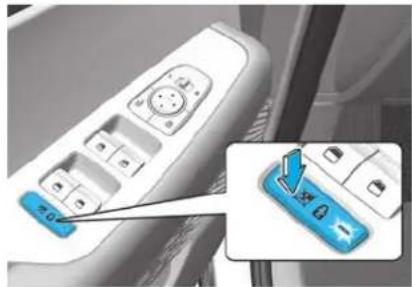
natural_image
Close-up of a car control panel with a blue button labeled '20' and an inset showing a blue button with a cursor (no text or symbols on the panel itself)If you push the Electronic child safety lock switch and the indicator illuminates, rear passengers cannot open the rear door from inside the vehicle. To cancel the Electronic child safety lock system, push the Electronic child safety lock system switch one more time and then the indicator turns off. The Safe Exit Assist (SEA) system is operated when the Electronic child safety lock system is activated and the Safe Exit Assist (SEA) function is selected in the cluster. However, the Safe Exit Assist (SEA) system does not automatically activate the Electronic child safety lock system.
The Electronic child safety lock system can be operated for approximately 10 minutes after the engine is turned off.
If your vehicle is equipped with the Electronic child safety lock system, the Child-protector rear door locks which is manually operated is not provided.
If Electronic child safety lock system is activated, rear passenger cannot open or close the rear window also. For more details, refer to "Windows" in this chapter.
CAUTION
OTM048424L
If the Electronic child safety lock system is not operated when pushing the Electronic child safety lock switch, the message is displayed and the alarm will sound.
If this occurs, have the vehicle inspected by an authorized HYUNDAI dealer.
Safe Exit Assist (SEA) System (if equipped)
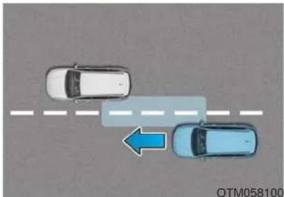
natural_image
Top-down view of two cars on a road with a blue arrow indicating direction (no text or symbols)-
The Safe Exit Assist system is provided to help prevent the passengers from opening a door by warning the passengers when an approaching vehicle from the rear area is detected after the vehicle stops.
-
When an approaching vehicle from the rear area is detected after the vehicle stops, the rear door does not unlock even when the driver tries to unlock the rear door using the Electronic child safety lock button. The "Check surroundings then try again" warning message appears on the cluster and a warning sounds.
However if you press the switch within 10 seconds after the warning message appears (the indicator on the switch will turn off), the system judges that the driver unlocked the door acknowledging the rear status and released regardless of the rear status.
- When an approaching vehicle from the rear is detected the moment the door is opened, the "Watch for traffic" warning message appears on the cluster and a warning sounds.
- The above 2 and 3 functions are activated when you select 'Driver Assistance → Blind-Spot Safety → Safe Exit Assistance (SEA)' from the User Settings mode in the cluster LCD display.
- The Electronic child safety lock system will operate for approximately 10 minutes after the ignition key is removed or turned to the LOCK (or OFF) position. After about 10 minutes, the indicator on the switch turns off and you cannot deactivate the Electronic child safety lock system. To deactivate the Electronic child safety lock system, press the Electronic child safety lock switch again with the ignition switch in the ON position or after starting the engine.
- When the power is supplied again after removing the battery or battery discharge while the child safety lock is in the lock position, press the child safety lock switch once again to match the state of the indicator on the child safety lock switch and actual status of the Electronic child safety lock system.
- If the airbag is activated while the child safety lock switch is ON (the indicator on the switch illuminates) it automatically switches OFF and the rear door is unlocked.
CAUTION
- The Safe Exit Assist (SEA) system may not operate normally if there is any vehicle or obstacle at the rear area of your vehicle.
- The Safe Exit Assist (SEA) system may not operate normally when a vehicle is coming rapidly two lanes over from your vehicle or a vehicle is approaching at a fast speed from the rear in the lane next to your vehicle.
- The Safe Exit Assist (SEA) system may be activated later than normal or may not operate normally if a vehicle is approaching fast from the rear of your vehicle.
- The Safe Exit Assist (SEA) system will not operate if there is a malfunction with the Blind-Spot Collision Warning (BCW) system as follows:
- When the BCW warning message appears When the BCW sensor or the sensor surrounding is polluted or covered
- When the BCW does not warn or warns wrongly
For more details, refer to cau-tions and limitations in "Blind-Spot Collision Warning (BCW)" in chapter 5.
WARNING
- The system does not detect every obstacle approaching the vehicle exit.
- The driver and passenger are responsible for any obstacles while exiting the vehicle.
Always check the surrounding before you exit the vehicle.
Rear Occupant Alert (ROA) System (if equipped)
The Rear Occupant Alert (ROA) system is provided to help prevent exiting the vehicle with the rear passenger left in the vehicle.
- 1st alert
- When you open the front door after opening and closing the rear door and turning off the engine, the "Check rear seats" warning message appears on the cluster.
- You can activate or deactivate the Rear Occupant Alert (ROA) system from the User Settings mode in the cluster LCD display. The option can be found under the following menu:
User Settings → Convenience → Rear Occupant Alert
- 2nd alert (if equipped)
- After the 1st alert the 2nd alert operates when any movement is detected in the vehicle after the driver's door is closed and all the doors are locked. The horn will activate for about 25 seconds. If the system continues to detect a movement the alert operates up to 8 times.
- Unlock the door with the remote key or smart key to stop the alert.
- The system detects movement in the vehicle for 24 hours after the door is locked.
- The 2nd alert is activated only after the prior activation of the 1st alert.
CAUTION
- Make sure that all the windows are closed. If the window is open, the alert may activate by the sensor detecting an unintended movement (e.g. wind or bugs).
■Cluster
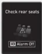
OLX2049120N
■Steering wheel
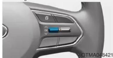
natural_image
Close-up of a car dashboard with control buttons and a battery icon (no readable text or symbols)- If you do not want to use the Rear Occupant Alert (ROA) system, press OK button on the steering wheel when the 1st alert is displayed on the cluster. Doing so will deactivate the 2nd alert once. (if equipped)
CAUTION
- If boxes or objects are stacked in the vehicle, the system may not detect the obstacle. Also, the warning may generate if the box or object falls off.
- The sensor may not operate normally if the senor is obscured by foreign substances.
- The alert may activate if movement in the driver or passenger seat is detected.
- The alert may activate with the doors locked due to car wash or surrounding vibration or noise.
- Inside movement detection is stopped under remote start (if equipped) status.
WARNING
• Even if your vehicle is equipped with the Rear Occupant Alert (ROA) system, always make sure you check the rear seat before you get off the vehicle.
The alert may not operate if:
- The movement does not continue for a certain period of time or the movement is small.
- The rear passenger is covered with an obstacle such as a blanket.
- Also, always be cautious of the passenger's safety as the detection function and 2nd alert may not operate according to the surrounding environment and certain conditions.
- If a child sits on a vehicle seat without a child restraint system.
THEFT-ALARM SYSTEM
This system helps to protect your vehicle and valuables. The horn will sound and the hazard warning lights will blink continuously if any of the following occur:
- A door is opened without using the remote key or smart key.
- The liftgate is opened without using the remote key or smart key.
- The engine hood is opened.
The alarm continues for 30 seconds (repeats 2 times unless the system is disarmed), then the system resets. To turn off the alarm, unlock the doors with the remote key or smart key.
The Theft Alarm System automatically sets 30 seconds after you lock the doors and the liftgate. For the system to activate, you must lock the doors and the liftgate from outside the vehicle with the remote key or smart key or by pressing the button on the outside of the door handle with the smart key in your possession.
The hazard warning lights will blink and the chime will sound once to indicate the system is armed.
Once the security system is set, opening any door, the liftgate, or the hood without using the remote key or smart key will cause the alarm to activate.
The Theft Alarm System will not set if the hood, the liftgate, or any door is not fully closed. If the system will not set, check the hood, the liftgate, or the doors are fully closed.
Do not attempt to alter this system or add other devices to it.
i Information
- Do not lock the doors until all passengers have left the vehicle. If the remaining passenger leaves the vehicle when the system is armed, the alarm will be activated.
- If the vehicle is not disarmed with the remote key or smart key, open the doors by using the mechanical key and place the ignition switch in the ON position (for remote key) or start the engine (for smart key) by directly pressing the ignition switch with the smart key.
- If the system is disarmed by unlocking the vehicle, but neither a door or the liftgate is opened within 30 seconds, the doors will relock and the system will rearm automatically.
DRIVER POSITION MEMORY SYSTEM (IF EQUIPPED)
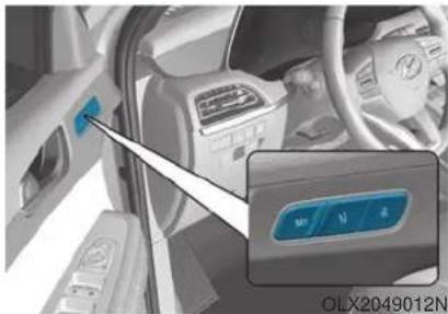
natural_image
Interior view of a car showing dashboard and steering wheel (no visible text or symbols)The Driver Position Memory System is provided to store and recall the following memory settings with a simple button operation.
- Driver's seat position (Power seat)
- Side view mirror position
- Instrument panel illumination intensity
- Head Up Display (HUD) position and brightness (if equipped)
WARNING
Never attempt to operate the driver position memory system while the vehicle is moving.
This could result in loss of control, and an accident causing death, serious injury, or property damage.
i Information
- If the battery is disconnected, the memory settings will be erased.
- If the Driver Position Memory System does not operate normally, have the system checked by an authorized HYUNDAI dealer.
CAUTION
To prevent the battery from being discharged, use the driver position memory system while engine is running and the vehicle is in the park position.
Storing Positions into Memory
- Shift to P (Park) position.
- Adjust the driver's seat position, side view mirror position, instrument panel illumination intensity and head-up display height/brightness to positions comfortable for the driver.
- Press the SET button. The system will beep once and notify you "Press button to save settings" on the cluster LCD display.
- Press one of the memory buttons (1 or 2) within 4 seconds. The system will beep twice when the memory has been successfully stored.
- "Driver 1 (or 2) settings saved" will appear on the cluster LCD display.
Recalling Positions from Memory
- Shift to P (Park) while the ignition switch is in the ON position.
- Press the desired memory button (1 or 2). The system will beep once, and then the driver's seat position, side view mirror position, instrument panel illumination intensity and head-up display height/brightness will automatically adjust to the stored positions.
- "Driver 1 (or 2) settings applied" will appear on the cluster LCD display.
i Information
- While recalling the "1" memory position, pressing the SET or 1 button temporarily stops the adjustment of the recalled memory position. Pressing the 2 button recalls the "2" memory position.
-
While recalling the "2" memory position, pressing the SET or 2 button temporarily stops the adjustment of the recalled memory position. Pressing the 1 button recalls the "1" memory position.
-
While recalling the stored positions, pressing one of the control buttons for the driver's seat, side view mirror, instrument panel illumination or head-up display will cause the movement of that component to stop and move in the direction that the control button is pressed.
Resetting the Driver's Seat Memory System
Take the following procedures to reset the driver's seat memory system, when it does not operate properly.
To reset the driver's seat memory system
- Place the ignition switch to the ON position, shift to P (Park), and open the driver's door.
- Operate the control switch to set the driver's seat and seatback to the foremost position.
- Simultaneously press the SET button and push forward the seat movement switch over 2 seconds.
While resetting the driver's seat memory system
- It starts with the notification sound.
- The driver's seat and seatback is adjusted to the rearward position with the notification sound.
- The driver's seat and seatback is re-adjusted to the default position (central position) with the notification sound.
However, in the following cases, the resetting procedure and the notification sound may stop.
- The memory button is pressed.
- The control switch is operated.
- The driving speed exceeds 2 mph (3 km/h).
- The driver's door is closed.
CAUTION
- If the reset is failed, initialize the system once again.
- Initialize the system after cleaning the obstacles surrounding of seat.
• After completing the initialization, adjust the driver position memory system again.
NOTICE
- Reattempt to do the resetting procedure again, when the resetting procedure incompletely stops or the notification sound do not stop.
- Make sure that there is no obstacle around the driver's seat in advance of resetting the driver's seat memory system.
Easy Access Function
The system will move the driver's seat automatically as follows:
- With remote key
- It will move the driver's seat rearward and downward when the ignition key is removed.
- It will move the driver's seat forward and upward when the ignition key is inserted.
- With smart key
- It will move the driver's seat rearward and downward when the Engine Start/Stop button is pressed to the OFF position.
- It will move the driver's seat forward and upward when the Engine Start/Stop button is pressed to the ACC or START position.
You can activate or deactivate the Easy Access Function from the User Settings mode in the cluster LCD display.
'Convenience → Seat Slide Easy Access → Off/Normal/Extended'.
'Convenience → Seat Height Easy Access'.
*“Seat (upward/downward) Easy Access” function may not operate below the specific seat height for preventing injury of the passenger.
For more details, refer to "LCD Display" in this chapter.
CAUTION
Driver should be cautious when using this function to assure no injury to passenger or child in the back seat. In case of emergency the driver has to stop movement of front seat (when easy access feature is activated) by pressing SET button or any of the driver seat control switches.
STEERING WHEEL
Electric Power Steering (EPS)
The system assists you with steering the vehicle. If the vehicle is turned off or if the power steering system becomes inoperative, you may still steer the vehicle, but it will require increased steering effort.
Should you notice any change in the effort required to steer during normal vehicle operation, have the system checked by an authorized HYUNDAI dealer.
NOTICE
- If the Electric Power Steering System does not operate normally, the warning light ( will illuminate on the instrument cluster. You may steer the vehicle, but it will require increased steering efforts. Take your vehicle to an authorized HYUNDAI dealer and have the system checked as soon as possible.
- When abnormality is detected in the electric power steering system, the steering assist function will stop. At this time, the warning light turns on or blinks on the cluster. The steering wheel may become difficult to control or operate. Have your vehicle checked immediately, after moving the vehicle to a safe zone.
i Information
The following symptoms may occur during normal vehicle operation:
- The steering effort may be high immediately after placing the ignition switch in the ON position.
This happens as the system performs the EPS system diagnostics. When the diagnostics are completed, the steering wheel effort will return to its normal condition. - A click noise may be heard from the EPS relay after the ignition switch is in the ON or LOCK/OFF position.
- Motor noise may be heard when the vehicle is at a stop or at a low driving speed.
- When you operate the steering wheel in low temperatures, abnormal noise may occur. If the temperature rises, the noise will disappear. This is a normal condition.
- When an error is detected from the EPS, the steering effort assist function will not be activated.
- When you operate the steering wheel in low temperatures, abnormal noise may occur. If the temperature rises, the noise will disappear. This is a normal condition. - When an error is detected from the EPS, the steering effort assist function will not be activated.
Instrument cluster warning lights may be on or the steering effort may be high. If these symptoms occur, drive the vehicle to a safe area as soon as it is safe to do so. Have the system checked by an authorized HYUNDAI dealer as soon as possible.
Tilt Steering / Telescopic Steering
When adjusting the steering wheel to a comfortable position, adjust the steering wheel so that it points toward your chest, not toward your face. Make sure you can see the instrument cluster warning lights and gauges. After adjusting, push the steering wheel both up and down to be certain it is locked in position. Always adjust the position of the steering wheel before driving.
WARNING
NEVER adjust the steering wheel while driving. This may cause loss of vehicle control resulting in an accident.
NOTICE
While adjusting the steering wheel height, please do not push or pull it hard since the fixture can be damaged.
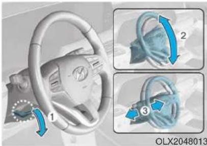
To adjust the steering wheel angle and height:
- Pull down the lock-release lever (1).
- Adjust the steering wheel to the desired angle (2) and distance forward/back (3).
- Pull up the lock-release lever to lock the steering wheel in place.
i Information
Sometimes the lock release lever may not engage completely. This may occur when the gears of the locking mechanism do not completely mesh. If this occurs, pull down on the lock-release lever, readjust the steering wheel again, and then pull back up on the release lever to lock the steering wheel in place.
Horn
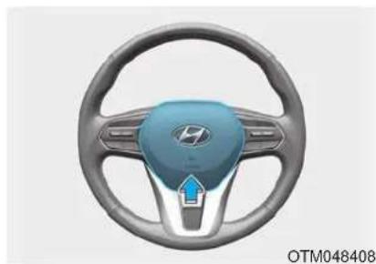
natural_image
Close-up of a car steering wheel with blue and gray components, featuring a logo on the head (no text or symbols visible)To sound the horn, press the area indicated by the horn symbol on your steering wheel (see illustration). The horn will operate only when this area is pressed.
NOTICE
Do not strike the horn severely to operate it, or hit it with your fist. Do not press on the horn with a sharp-pointed object.
Heated Steering Wheel (if equipped)
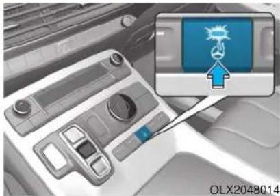
natural_image
Interior view of a car dashboard with a highlighted blue icon showing a lightning bolt (no text or symbols on the main subject)When the ignition switch is in the ON position or when the engine is running, press the heated steering wheel button to warm the steering wheel. The indicator on the button will illuminate.
To turn the heated steering wheel off, press the button again. The indicator on the button will turn off.
- The heated steering wheel defaults to the OFF position whenever the ignition switch is in the ON position.
i Information
The heated steering wheel will turn off automatically approximately 30 minutes after the heated steering wheel is turned on.
NOTICE
Do not install any cover or accessory on the steering wheel. The cover or accessory could cause damage to the heated steering wheel system.
MIRRORS
Inside Rearview Mirror
Before driving your vehicle, check to see that your inside rearview mirror is properly positioned. Adjust the rearview mirror so that the view through the rear window is properly centered.
WARNING
Make sure your line of sight is not obstructed. Do not place objects in the rear seat, cargo area, or behind the rear head-rests which could interfere with your vision through the rear window.
WARNING
To prevent serious injury during an accident or deployment of the air bag, do not modify the rearview mirror and do not install a wide mirror.
WARNING
NEVER adjust the mirror while driving. This may cause loss of vehicle control resulting in an accident.
NOTICE
When cleaning the mirror, use a paper towel or similar material dampened with glass cleaner. Do not spray glass cleaner directly on the mirror as this may cause the liquid cleaner to enter the mirror housing.
Day/night rearview mirror (if equipped)
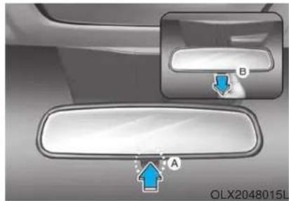
natural_image
Interior view of a car showing a mirror and side panel with blue arrows pointing to points A and B (no text or symbols present)Make this adjustment before you start driving and while the day/night lever is in the day position.
Pull the day/night lever towards you to reduce glare from the headlights of the vehicles behind you during night driving.
Remember that you lose some rearview clarity in the night position.
Electrochromatic Mirror (ECM) (if equipped)
Some vehicles come equipped with an electrochromic mirror that helps control glare while driving at night or under low light driving conditions.
When the engine is running, the glare is automatically controlled by the sensor mounted in the rearview mirror. The sensor detects the light level around the vehicle, and automatically adjusts to control the head-lamp glare from vehicles behind you.
Whenever the shift button is placed in R (Reverse), the mirror will automatically go to the brightest setting in order to improve the driver's view behind the vehicle.
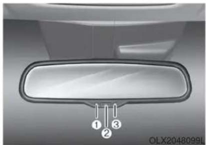
natural_image
Top-down view of a car front mirror with numbered labels (1, 2, 3) pointing to the lens area (no text or symbols on the mirror itself)NOTICE
When cleaning the mirror, use a paper towel or similar material dampened with glass cleaner. Do not spray glass cleaner directly on the mirror as that may cause the liquid cleaner to enter the mirror housing.
Electrochromatic Mirror (ECM) with homelink system (if equipped)
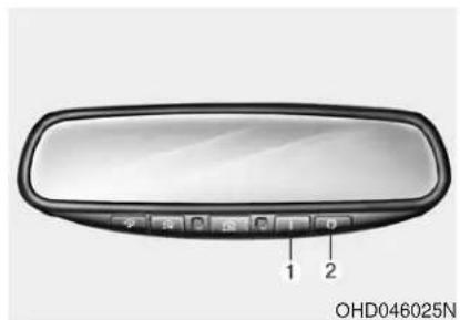
To operate the electric rearview mirror
Press the I button (1) to turn the automatic-dimming function on. The mirror indicator light will illuminate.
Press the O button (2) to turn the automatic-dimming function off. The mirror indicator light will turn off.
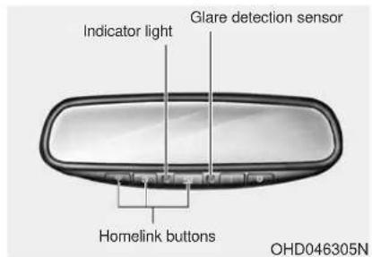
HomeLink® Wireless Control System Your new mirror comes with an integrated HomeLink Universal Transceiver, which allows you to program the mirror to activate your garage door(s), estate gate, home lighting, etc. The mirror actually learns the codes from your various existing transmitters.
WARNING
- When programming the HomeLink® Wireless Control System, you may be operating a garage door or gate operator. Make sure that people and objects are out of the way of the moving door or gate to prevent potential harm or damage.
- Do not use HomeLink with any garage door opener that lacks the safety stop and reverse feature as required by U.S. federal safety standards. (This includes any garage door opener model manufactured before April 1, 1982.) A garage door opener which cannot detect an object, signaling the door to stop and reverse, does not meet current U.S. federal safety standards. Using a garage door opener without these features increases risk of serious injury or death. For more details, call 1-800-355-3515 or on the internet at www.home-link.com.
Retain the original transmitter for future programming procedures (i.e., new vehicle purchase). It is also suggested that upon the sale of the vehicle, the programmed HomeLink buttons be erased for security purposes (follow step 1 in the "Programming" portion of this text).
Programming
Your vehicle may require the ignition switch to be turned to the ACC position for programming and/or operation of HomeLink. It is also recommended that a new battery be replaced in the hand-held transmitter of the device being programmed to HomeLink for quicker training and accurate transmission of the radio-frequency.
Follow these steps to train your HomeLink mirror:
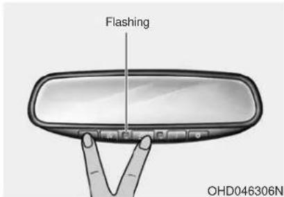
- When programming the buttons for the first time, press and hold the left and center buttons (☐) simultaneously for approximately 20 seconds until the indicator light begins to flash. (This procedure erases the factory-set default codes. Do not perform this step to program additional hand-held transmitters.)
NOTICE
For non rolling code garage door openers, follow steps 2 - 3.
For rolling code garage door openers, follow steps 2 - 6.
For Canadian Programming, please follow the Canadian Programming section.
For help with determining whether your garage is non-rolling code or rolling code, please refer to the garage door openers owner's manual or contact HomeLink customer service at 1-800-355-3515.
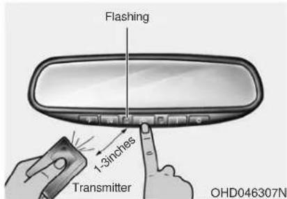
-
Press and hold the button on the HomeLink system you wish to train and the button on the transmitter while the transmitter is approximately 1 to 3 inches away from the mirror. Do not release the buttons until step 3 has been completed.
-
The HomeLink indicator light will flash, first slowly and then rapidly. When the indicator light flashes rapidly, both buttons may be released. (The rapid flashing light indicates successful programming of the new frequency signal.)
NOTICE
Some gate operators and garage door openers may require you to replace step #3 with the "cycling" procedure noted in the "Canadian Programming" section of this document.
Rolling code programming
To train a garage door opener (or other rolling code equipped devices) with the rolling code feature, follow these instructions after completing the "Programming" portion of this text. (A second person may make the following training procedures quicker & easier.)
-
Locate the "learn" or "smart" button on the device's motor head unit. Exact location and color of the button may vary by product brand. If there is difficulty locating the "learn" or "smart" button, reference the device's owner's manual or contact HomeLink at 1-800-355-3515 or on the internet at www.homelink.com.
-
Press and release the "learn" or "smart" button on the device's motor head unit. You have 30 seconds to complete step number 6.
- Return to the vehicle and firmly press and release the programmed HomeLink button up to three times. The rolling code equipped device should now recognize the HomeLink signal and activate when the HomeLink button is pressed. The remaining two buttons may now be programmed if this has not previously been done. Refer to the "Programming" portion of this text.
Operating HomeLink
To operate, simply press the programmed HomeLink button. Activation will now occur for the trained product (garage door, security system, entry door lock, estate gate, or home or office lighting). For convenience, the hand-held transmitter of the device may also be used at any time. The HomeLink Wireless Controls System (once programmed) or the original hand-held transmitter may be used to activate the device (e.g. garage door, entry door lock, etc.). In the event that there are still programming difficulties, contact HomeLink at 1-800-355-3515 or on the internet at www.homelink.com.
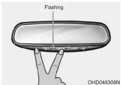
Erasing programmed HomeLink buttons
To erase the three programmed buttons (individual buttons cannot be erased):
- Press and hold the left and center buttons simultaneously, until the indicator light begins to flash (approximately 20 seconds). Release both buttons. Do not hold for longer than 30 seconds.
HomeLink is now in the train (or learning) mode and can be programmed at any time.
Gate operator & Canadian programming
During programming, your handheld transmitter may automatically stop transmitting. Continue to press the Integrated HomeLink® Wireless Control System button (note steps 2 through 3 in the Programming portion of this document) while you press and re-press ("cycle") your handheld transmitter every two seconds until the frequency signal has been learned. The indicator light will flash slowly and then rapidly after several seconds upon successful training.
FCC ID: NZLZTVHL3
IC: 4112A-ZTVHL3
i Information
This device complies with Part 15 of the FCC Rules.
Operation is subject to the following three conditions:
-
This device may not cause harmful interference.
-
This device must accept any interference received, including interference that may cause undesired operation.
-
The transceiver has been tested and complies with FCC and Industry Canada rules. Changes or modifications not expressly approved by the party responsible for compliance could void the user's authority to operate the device.
Side View Mirrors
natural_image
Side view of a car's front window showing a blue plastic object on the side (no text or symbols visible)Make sure to adjust the side view mirrors to your desired position before you begin driving.
Your vehicle is equipped with both left-hand and right-hand side view mirrors. The mirrors can be adjusted remotely with the remote switch. The side view mirrors can be folded to help prevent damage when going through an automatic car wash or when passing through a narrow street.
The right side view mirror is convex. Objects seen in the mirror are closer than they appear.
Use the inside rear view mirror or look back directly to determine the actual distance of other vehicles prior to changing lanes.
WARNING
Do not adjust or fold the side view mirrors while driving. This may cause loss of vehicle control resulting in an accident.
NOTICE
- Do not scrape ice off the mirror face; this may damage the surface of the glass.
- If the mirror is jammed with ice, do not adjust the mirror by force. Use an approved spray de-icer (not radiator antifreeze) spray, or a sponge or soft cloth with very warm water, or move the vehicle to a warm place and allow the ice to melt.
NOTICE
Do not clean the mirror with harsh abrasives, fuel or other petroleum based cleaning products.
Side view mirror adjustment
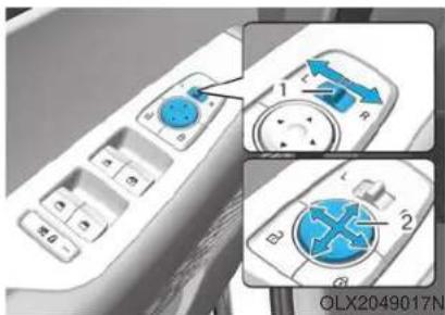
Adjusting the side view mirrors
- Move the lever (1) either to the L (left side) or R (right side) to select the side view mirror you would like to adjust.
- Use the mirror adjustment control switch (2) to position the selected mirror up, down, left or right.
- After adjustment, move the lever (1) to the middle to prevent inadvertent adjustment.
NOTICE
- The mirrors stop moving when they reach the maximum adjusting angles, but the motor continues to operate while the switch is pressed. Do not press the switch longer than necessary, because this can damage the motor.
- Do not attempt to adjust the side view mirrors by hand, because this can damage the motor.
Folding the side view mirrors
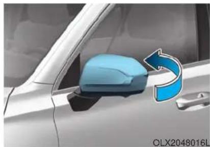
natural_image
Side view of a car's side mirror and dashboard (no text or symbols visible)To fold the side view mirrors, grasp the housing of the mirror and then fold it inwards.
Reverse Parking Aid Function (if equipped)
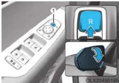
When you move the shift button to the R (Reverse) position, the side view mirror(s) will rotate downwards to aid with driving in reverse. The position of the side view mirror switch (1) determines whether or not the mirrors will move:
Left/Right : When either the L (Left) or R (Right) switch is selected, both side view mirrors will move.
Neutral : When neither switch is selected, the side view mirrors will not move.
The side view mirrors will automatically revert to their original positions if any of the following occur:
- The ignition switch is placed to either the LOCK/OFF position or the ACC position.
- The shift button is selected to any position except R (Reverse).
- The remote control side view mirror switch is not selected.
WINDOWS
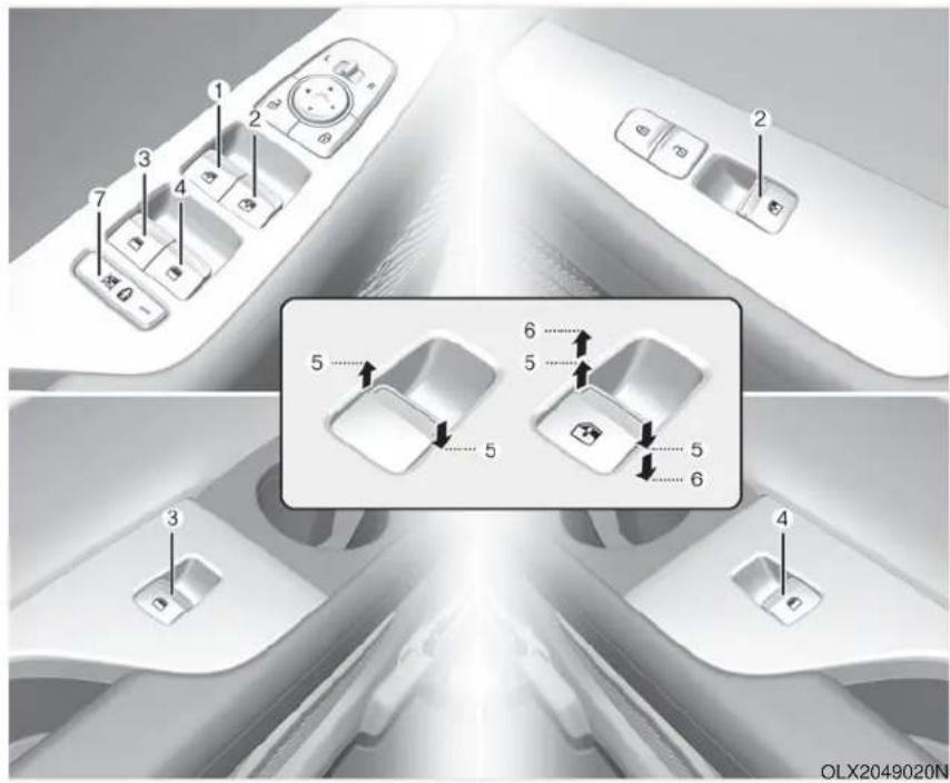
(1) Driver's door power window switch
(2) Front passenger's door power window switch
(3) Rear door (left) power window switch
(4) Rear door (right) power window switch
(5) Window opening and closing
(6) Automatic power window
(7) Power window lock switch
Power Windows
The ignition switch must be in the ON position to be able to raise or lower the windows. Each door has a Power Window switch to control that door's window. The driver has a Power Window Lock switch which can block the operation of passenger windows. The power windows will operate for approximately 10 minutes after the ignition switch is placed in the ACC or LOCK/OFF position. However, if the front doors are opened, the Power Windows will not operate even within the 10 minute period.
WARNING
To avoid serious injury or death, do not extend your head, arms or body outside the windows while driving.
i Information
- In cold and wet climates, power windows may not work properly due to freezing conditions.
- While driving with the rear windows down or with the sunroof (if equipped) opened (or partially opened), your vehicle may demonstrate a wind buffeting or pulsation noise. This noise is normal and can be reduced or eliminated by taking the following actions. If the noise occurs with one or both of the rear windows down, partially lower both front windows approximately one inch. If you experience the noise with the sunroof open, slightly close the sunroof.
Window opening and closing
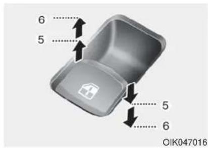
To open:
Press the window switch down to the first detent position (5). Release the switch when you want the window to stop.
To close:
Pull the window switch up to the first detent position (5). Release the window switch when you want the window to stop.
Auto up/down window (if equipped)
Pressing or pulling up the power window switch momentarily to the second detent position (6) completely lowers or lifts the window even when the switch is released. To stop the window at the desired position while the window is in operation, pull up or press down and release the switch.
To reset the power windows
If the power windows do not operate normally, the automatic power window system must be reset as follows:
- Place the ignition switch to the ON position.
- Close the window and continue pulling up on the power window switch for at least one second.
If the power windows do not operate properly after resetting, have the system checked by an authorized HYUNDAI dealer.
WARNING
The automatic reverse feature doesn't activate while resetting the power window system. Make sure body parts or other objects are safely out of the way before closing the windows to avoid injuries or vehicle damage.
Automatic reverse (if equipped)
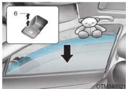
If a window senses any obstacle while it is closing automatically, it will stop and lower approximately 12 inches (30 cm) to allow the object to be cleared.
If the window detects the resistance while the power window switch is pulled up continuously, the window will stop upward movement then lower approximately 1 inch (2.5 cm).
If the power window switch is pulled up continuously again within 5 seconds after the window is lowered by the automatic window reverse feature, the automatic window reverse will not operate.
i Information
The automatic reverse feature is only active when the "Auto Up" feature is used by fully pulling up the switch to the second detent.
WARNING
Make sure body parts or other objects are safely out of the way before closing the windows to avoid injuries or vehicle damage. Objects less than 0.16 inch (4 mm) in diameter caught between the window glass and the upper window channel may not be detected by the automatic reverse window and the window will not stop and reverse direction.
NOTICE
Do not install any accessories on the windows. The automatic reverse feature may not operate.
Power window lock switch
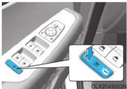
natural_image
Close-up of a car air conditioner control panel with a blue indicator button and an inset showing the same component (no text or symbols visible)The driver can disable the power window switches on the rear passenger doors by pressing the power window lock switch.
When the power window lock switch is pressed:
- The rear passenger control will not be able to operate the rear passenger power window
- Note that the front passenger control is still able to operate the front passenger window, and that the driver master control can still operate all the power windows.
WARNING
Do not allow children to play with the power windows. Keep the driver's door power window lock switch in the LOCK position. Serious injury or death can result from unintentional window operation by a child.
NOTICE
- To prevent possible damage to the power window system, do not open or close two windows or more at the same time. This will also ensure the longevity of the fuse.
- Never try to operate the main switch on the driver's door and the individual door window switch in opposite directions at the same time. If this is done, the window will stop and cannot be opened or closed.
SUNROOF (IF EQUIPPED)
Sunroof (if equipped)
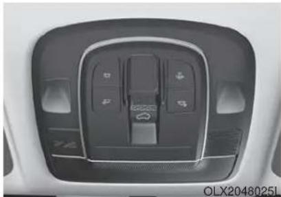
natural_image
Interior view of a car dashboard with control panel and buttons (no readable text or symbols)If your vehicle is equipped with a sunroof, you can slide or tilt your sunroof with the sunroof control lever located on the overhead console.
The ignition switch must be in the ON position before you can open or close the sunroof.
The sunroof can be operated for approximately 10 minutes after the ignition switch is removed or turned to the ACC or LOCK/OFF position.
However, if the front doors are opened, the sunroof cannot be adjusted even within the 10 minutes period.
Dual wide sunroof (if equipped)
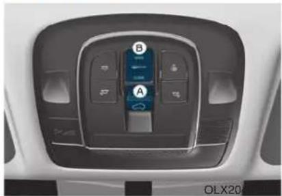
natural_image
Interior view of a car dashboard with labeled buttons and a central touchscreen display (no readable text or symbols)A: Front sunroof control lever.
B: Rear blind control button
If your vehicle is equipped with a dual wide sunroof, you can slide or tilt your sunroof with the sunroof control lever located on the overhead console. And you can slide your rear blind with the rear blind control button.
The ignition switch must be in the ON position before you can open or close the sunroof.
The sunroof can be operated for approximately 10 minutes after the ignition key is removed or turned to the ACC or LOCK (or OFF) position.
However, if the front door is opened, the sunroof cannot be operated even within 10 minutes.
i Information
- In cold and wet climates, the sun-roof may not work properly due to freezing conditions.
• After the vehicle is washed or in a rainstorm, be sure to wipe off any water that is on the sunroof before operating it.
WARNING
- Never adjust the sunroof or sunshade while driving. This could result in loss of control and an accident that may cause death, serious injury, or property damage.
• Make sure heads, hands, arms or any other body parts or objects are out of the way before operating the sunroof.
- Do not extend your head, arms or body outside the sunroof while driving, to avoid serious injury.
- Do not leave the engine running and the key in your vehicle with unsupervised children. Unattended children could operate the sunroof, which could result in serious injury.
- The sunroof is made of glass, subject to break in case of an accident. Passengers without the appropriate protection (e.g. seat belt, CRS, etc.) on may project out through the broken glass and may be seriously injured or even result in death.
- Do not sit on the top of the vehicle. It may cause injury or vehicle damage.
NOTICE
- Do not continue to move the sun-roof control lever after the sun-roof is fully opened, closed, or tilted. Damage to the motor or system components could occur.
- Make sure the sunroof is closed fully when leaving your vehicle. If the sunroof is left open, rain or snow may wet the interior of the vehicle. Also, leaving the sunroof open when the vehicle is unattended may invite theft.
Sunshade
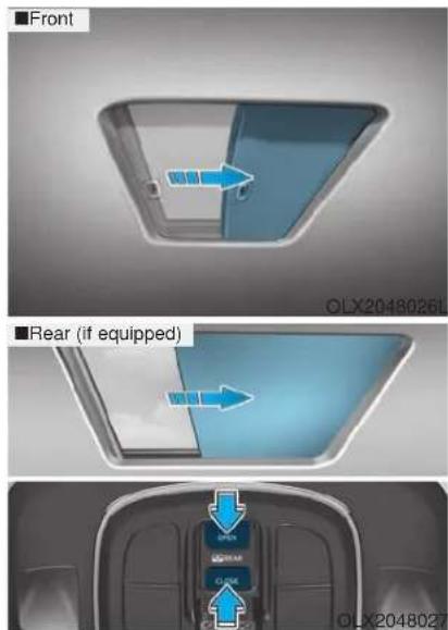
Front
• To open the sunshade, pull the sunroof sunshade backward.
• To close the sunshade, pull the sunroof sunshade forward.
Rear (if equipped)
- To open the rear blind, push the rear blind OPEN button.
- To close the rear blind, push the rear blind CLOSE button.
i Information
Activating the control lever to the first detent requires only a very light touch.
Sunroof Opening and Closing
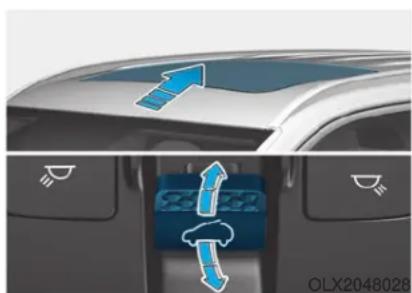
natural_image
Top-down view of a car's rearview showing airflow direction indicators (no text or symbols)To open:
Press the sunroof control lever backward to the first detent position. Release the switch when you want the sunroof to stop.
To close:
Press the sunroof control lever forward to the first detent position. Release the switch when you want the sunroof to stop.
Sliding the Sunroof
Pressing the sunroof control lever backward or forward momentarily to the second detent position completely opens or closes the sunroof even when the switch is released. To stop the sunroof at the desired position while the sunroof is in operation, press the sunroof control lever backward or forward and release the switch.
Tilting the Sunroof (Front)
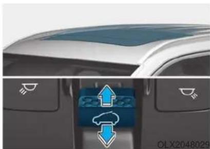
natural_image
Top-down view of a car's rearview showing airflow direction indicators (no text or symbols)Tilt the sunroof open:
Push the sunroof control lever upward until the sunroof moves to the desired position.
To close the sunroof:
Push the sunroof control lever forward until the sunroof closes.
Automatic reverse (if equipped)
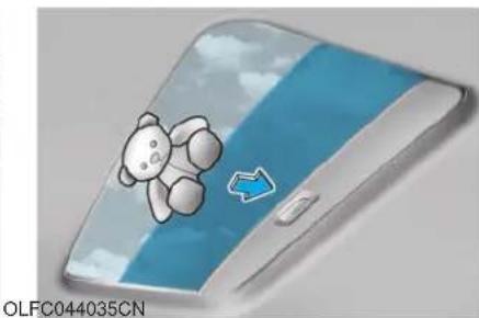
natural_image
Illustration of a cartoon bear on a smartphone screen with blue sky and arrow (no text or symbols)If the sunroof senses any to an obstacle while it is closing automatically, it will reverse direction then stop to allow the object to be cleared.
WARNING
Small objects that can get caught between the sunroof glass and the front glass channel may not be detected by the automatic reverse system. In this case, the sunroof glass will not detect the object and will not reverse direction.
NOTICE
- Periodically remove any dirt that may accumulate on the sunroof guide rail or between the sun-roof and roof panel which can make a noise.
- Do not try to open the sunroof when the temperature is below freezing or when the sunroof is covered with snow or ice, otherwise the motor could be damaged. In cold and wet climates, the sunroof may not work properly.
Resetting the Sunroof
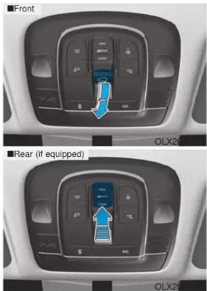
The sunroof may need to be reset if the following conditions occur:
- The battery is discharged or disconnected or the sunroof fuse has been replaced or disconnected
- The sunroof control lever is not operating correctly
To reset the sunroof, perform the following steps:
- Turn the engine on.
- Push the control lever forward. The sunroof will close completely depending on the condition of the sunroof.
- Release the control lever until the sunroof does not move.
- Push the control lever forward about 10 seconds.
- When the sunroof is in the close position :
The glass will slightly move up and down.
Do not release the lever until the operation is completed.
If you release the lever during operation, try again from step 2.
- Within 3 seconds, push the control lever forward until the sunroof operates as follows: Slide Open → Slide Close.
Do not release the lever until the operation is completed.
If you release the lever during operation, try again from step 2.
- Release the sunroof control lever after all operation has completed. The sunroof system has been reset.
i Information
If you do not reset the sunroof, it may not work properly.
Resetting the rear sunshade (if equipped)
The rear sunshade may need to be reset if the following conditions occur:
- Battery is discharged or disconnected or the related fuse has been replaced or disconnected
- The rear sunshade does not normally operate
To reset the rear sunshade, perform the following steps:
- Turn the engine on.
- Push the rear sunshade CLOSE button. The rear sunshade will close completely.
- Push the rear sunshade CLOSE button about 10 seconds.
The rear sunshade will slightly move. Do not release the CLOSE button until the operation is completed. If you release the CLOSE button, try again from step 2.
- Within 3 seconds, push the CLOSE button until the rear sun-shade operates as follows: Open → Close
Do not release the CLOSE button until the operation is completed. If you release the CLOSE button during operation, try again from step 2.
- Release the CLOSE button after all operation has completed.
The rear sunshade system has been reset.
Sunroof Open Warning (if equipped)
■Type A
OLX2048108
natural_image
Top-down view of a car inside a circular tunnel or track, labeled 'Type B' and 'OLX2049140N' (no other text or symbols)- If the driver turns off the engine when the sunroof is not fully closed, the warning chime will sound for approximately 3 seconds and the sunroof open warning will appear on the cluster LCD display.
- If the driver turns off the engine and opens the door when the sunroof is not fully closed, the sunroof open warning will appear on the cluster LCD display until the door is closed or the sunroof is fully closed.
Close the sunroof securely when leaving your vehicle.
EXTERIOR FEATURES
Hood
Opening the hood
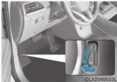
natural_image
Interior view of a car showing dashboard and steering wheel (no visible text or symbols)- Park the vehicle and set the parking brake.
- Pull the release lever to unlatch the hood. The hood should pop open slightly.
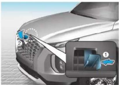
natural_image
Close-up illustration of a car's front grille and dashboard, showing blue airflow arrows (no text or symbols)- Go to the front of the vehicle, raise the hood slightly, push up the secondary latch (1) inside of the hood center and lift the hood (2). After it has been raised about halfway, it will raise completely by itself.
Closing the hood
- Before closing the hood, check in and around the engine compartment to ensure the following:
- Any tools or other loose objects are removed from the engine room area or hood opening area
- All glove, rags, or other combustible material is removed from the engine compartment
- All filler caps are tightly and correctly installed
- Lower the hood halfway (lifted approximately 12 inches (30 cm) from the closed position) and push down to securely lock in place. Then double check to be sure the hood is secure. If the hood can be raised slightly, it is not securely locked. Open it again and close it with more force.
WARNING
- Before closing the hood, ensure all obstructions are removed from around the hood opening.
• Always double check to be sure that the hood is firmly latched before driving away. Check there is no hood open warning light or message displayed on the instrument cluster. Driving with the hood opened may cause a total loss of visibility, which might result in an accident. - Do not move the vehicle with the hood in the raised position, as vision is obstructed, which might result in an accident, and the hood could fall or be damaged.
Non-Powered Liftgate (if equipped)
Opening the liftgate
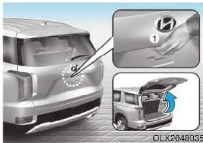
Before attempting to open the lift-gate, make sure the vehicle is in P (Park). To open the liftgate, perform one the following:
- Unlock all doors with the Door Unlock button on your remote key or smart key. From outside press the liftgate handle switch and open the liftgate.
- From outside press the liftgate handle switch and open the lift-gate.
Closing the liftgate
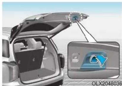
natural_image
Exterior view of a car trunk with open lid and internal door, showing a close-up inset of the door (no text or symbols visible)Lower the liftgate lid and press down until it locks. To be sure the liftgate lid is securely fastened, always check by trying to pull it up again without pressing the liftgate handle switch.
i Information
In cold and wet climates, door lock and door mechanisms may not work properly due to freezing conditions.
WARNING
The liftgate swings upward. Make sure no objects or people are near the rear of the vehicle when opening the liftgate.
NOTICE
Make certain that you close the liftgate before driving your vehicle. Possible damage may occur to the liftgate struts and mounting hinges if the liftgate is not closed prior to driving.
WARNING
Always keep the liftgate completely closed while the vehicle is in motion. If it is left open or ajar, poisonous exhaust gases containing carbon monoxide (CO) may enter the vehicle and serious illness or death may result.
WARNING
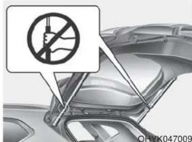
Do not hold on to or try to pull on the liftgate strut. Be aware that the deformation of the liftgate strut may cause vehicle damage and risk of injury.
Emergency liftgate safety release
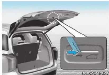
natural_image
Interior view of a car trunk with open lid and highlighted rear compartment showing airflow or ventilation (no text or symbols)Your vehicle is equipped with an emergency liftgate safety release lever located on the bottom of the lift-gate inside the vehicle.
To unlock and open the liftgate manually from inside the luggage compartment, perform the following steps:
- Push the release lever to the right by a key.
- Push up the liftgate.
WARNING
- Be aware of the location of the emergency liftgate safety release lever in your vehicle and know how to open the liftgate using the safety release lever.
- No one should be allowed to occupy the luggage compartment of the vehicle at any time. The luggage compartment is a very dangerous location in the event of a crash.
- Use the release lever for emergencies only. Use extreme caution, especially while the vehicle is in motion.
Power Liftgate (if equipped)
Power liftgate button
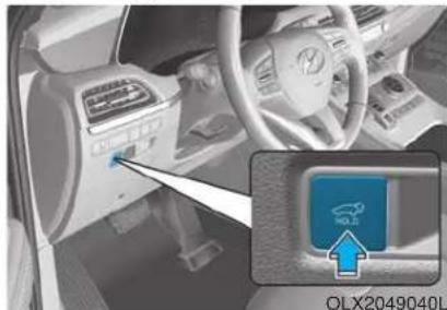
natural_image
Interior view of a car dashboard with a blue indicator light and a blue circular logo on the right (no readable text or symbols)Power liftgate setting
When the ignition switch is in the ON position and the shift button is in P (Park), the power liftgate can be opened by using the console button on the dash.
Before using the power liftgate, make sure the power liftgate option is selected in the User Setting modes in the cluster LCD display.
'User Settings → Door → Power Liftgate'
Also, the speed of the power liftgate can be adjusted in the User Settings mode in the cluster LCD display.
'User Settings → Door → Power Liftgate Speed → Normal / Fast'
- If the power liftgate function turns off or the liftgate is not fully closed, you cannot adjust the power liftgate speed.
- Initial speed of power liftgate is set as "Fast".
For more details, refer to "LCD Display" in this chapter.
i Information
The power liftgate operates only when the automatic shift button is in P (Park).
WARNING
Never leave children unattended in your vehicle. Children might operate the power liftgate. Doing so could result in injury to themselves or others, and could damage the vehicle.
WARNING
Make sure there are no people or objects around the liftgate before operating the power liftgate. Wait until the liftgate is opened fully and stopped before loading or unloading cargo or passengers from the vehicle.
NOTICE
Do not close or open the power liftgate manually. This may cause damage to the power liftgate. If it is necessary to close or open the power liftgate manually when the battery is discharged or disconnected, do not apply excessive force.
Opening the liftgate
The power liftgate will open automatically by doing one of the following:
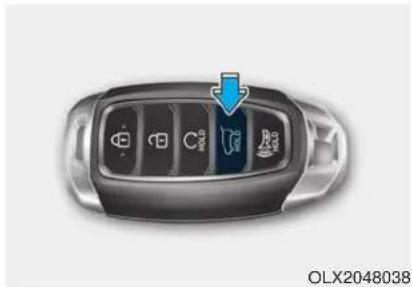
natural_image
Top-down view of a car's front panel with icons and a blue arrow pointing to the control panel (no text or symbols on the panel itself)Smart key liftgate unlock button Press and hold the liftgate unlock button on the smart key.
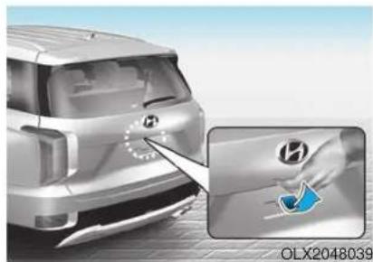
natural_image
Illustration of a car rear bumper with a hand placing a blue logo, no text or symbols presentPower liftgate handle switch
Press the liftgate outside handle switch while having the smart key with you.
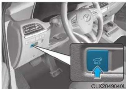
natural_image
Interior view of a car showing the dashboard and steering wheel, with a blue 'HOLD' button labeled (no readable text or symbols beyond branding)Power liftgate button
Press the power liftgate button for approximately one second.
In order to suddenly stop the movement of the liftgate while it is operating, quickly press the power liftgate button.
Closing the liftgate
The power liftgate will close automatically by doing one of the following:
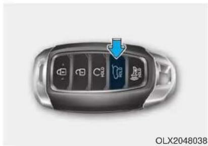
natural_image
Top-down view of a car's front panel with icons and a blue arrow pointing to the left side (no text or symbols on the panel itself)Smart key liftgate unlock button
Press and hold the liftgate unlock button on the smart key when the liftgate is opened. The liftgate will close and lock automatically.
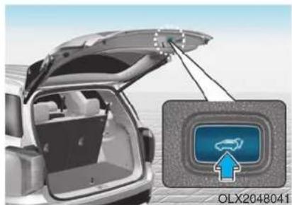
natural_image
Exterior view of a car trunk with open lid and attached cable, showing a close-up of a blue circular logo (no text or symbols on the main image)Power liftgate inner button
Press the power liftgate inner button for approximately 1 second. The liftgate will close and lock automatically.
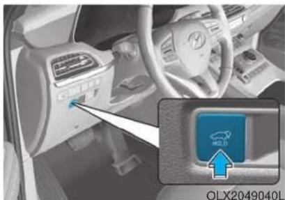
Power liftgate button
Press the power liftgate button for approximately one second. In order to suddenly stop the movement of the liftgate while it is operating, quickly press the power liftgate button.
In order to suddenly stop the movement of the liftgate while it is operating, quickly press the power liftgate button.
Power liftgate non-opening conditions
The power liftgate does not open when the vehicle is in motion.
WARNING
The chime will sound if you drive with the liftgate opened. Stop your vehicle immediately at a safe place and check if your liftgate is opened.
CAUTION
Operating the power liftgate more than 5 times continuously could cause damage to the operating motor. In this case, the power liftgate system enters into thermal protection mode to prevent the motor from overheating. In thermal protection mode the power liftgate will not operate. If any of the power liftgate buttons are pressed to try to open the liftgate, the chime will sound 3 times but the liftgate will remain closed.
Allow the power liftgate system to cool for about 1 minute before operating the system again.
NOTICE
- The power liftgate can be operated when the engine is not running. However, the power liftgate operation consumes a large amount of electric power.
To prevent the battery from being discharged, do not operate it excessively (e.g. more than 5 times repeatedly).
• To prevent the battery from being discharged, do not leave the power liftgate in the open position for a long time.
- Do not modify or repair any part of the power liftgate by yourself. This must be done by an authorized HYUNDAI dealer.
- When jacking up the vehicle to change a tire or repair the vehicle, do not operate the power liftgate. This could cause the power liftgate to operate improperly.
- In cold and wet climates, the power liftgate may not work properly due to freezing conditions.
Automatic reversal
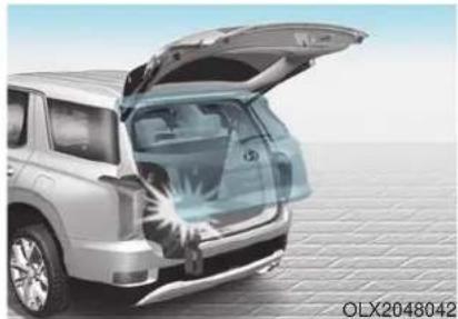
natural_image
Exterior view of a silver SUV with its open trunk showing internal engine compartment (no text or symbols visible)During power opening and closing if the power liftgate is blocked by an object or part of the body, the power liftgate may be able to detect the resistance.
If resistance is detected while opening or closing the power liftgate, the liftgate will stop and move in the opposite direction.
However, in some instances the automatic reversal system may not detect the object if it is too soft or is very thin, or if the liftgate is almost fully closed near the latched position. Caution should be taken to prevent any objects from obstructing the lift-gate opening.
If the automatic reversal feature operates more than 2 times while attempting to open or close the liftgate, the power liftgate may stop at that position. If this occurs, carefully close the liftgate manually, and then try to operate the power liftgate automatically again.

WARNING
Never intentionally place any object or part of your body in the path of the power liftgate to make sure the automatic reversal operates.

CAUTION
Do not put heavy objects on the power liftgate before you operate the power liftgate feature. Additional weight may damage the operation of the system.
How to reset the power liftgate
If the battery has been discharged or disconnected, or if the power liftgate fuse has been replaced or removed, reset the power liftgate by performing the following procedure:
- Press the P (Parking) button.
-
Press the power liftgate inner button and the power liftgate outer handle button simultaneously for more than 3 seconds. The chime will sound.
-
Close the liftgate manually.
If the power liftgate does not work properly after the above procedure, have the system checked by an authorized HYUNDAI dealer.
NOTICE
When operating the power liftgate, the gear shift button must be in the (P) park position in order to operate normally.
Power liftgate opening height user setting
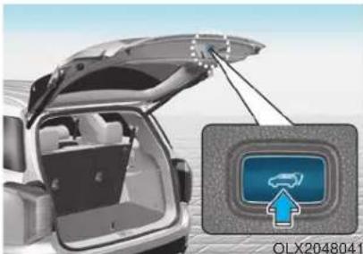
natural_image
Exterior view of a car trunk with open lid and attached cable, showing a close-up of the front panel (no text or symbols visible)Follow the instructions below to set the fully open height of the power lift-gate:
- Position the liftgate manually to the height you prefer.
- Press the power liftgate inner button for more than 3 seconds.
- Close the liftgate manually after hearing the buzzer sound.
The liftgate will open to the manually adjusted height that was set.

WARNING
Always keep the liftgate completely closed while the vehicle is in motion. If it is left open or ajar, poisonous exhaust gases containing carbon monoxide (CO) may enter the vehicle and serious illness or death may result.

WARNING
Rear cargo area
Occupants should never ride in the rear cargo area where no restraints are available. To avoid injury in the event of an accident or sudden stops, occupants should always be properly restrained.
Emergency liftgate safety release
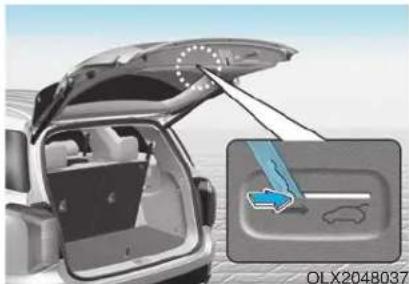
natural_image
Interior view of a car trunk with open lid and highlighted rear door, showing internal components (no text or symbols)Your vehicle is equipped with an emergency liftgate safety release lever located on the bottom of the lift-gate inside the vehicle.
To unlock and open the liftgate manually from inside the luggage compartment, perform the following steps:
- Push the release lever to the right by using a key.
- Push up the liftgate.
WARNING
- Be aware of the location of the emergency liftgate safety release lever in your vehicle and know how to open the liftgate using the safety release lever.
- No one should be allowed to occupy the luggage compartment of the vehicle at any time. The luggage compartment is a very dangerous location in the event of a crash.
- Use the release lever for emergencies only. Use extreme caution, especially while the vehicle is in motion.
Smart Liftgate (if equipped)
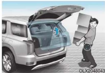
natural_image
Illustration of a person loading boxes into a car trunk (no text or symbols)On vehicles equipped with a smart key, the liftgate can be opened with hands-free activation using the Smart Liftgate system.
How to use the Smart Liftgate
The hands-free smart liftgate system can be opened automatically when the following conditions are met:
- The Smart Liftgate option is enabled in the User Settings in the cluster LCD display
- The Smart Liftgate is activated and ready 15 seconds after all the doors are closed and locked
- The Smart Liftgate will open when the smart key is detected in the area behind the vehicle for 3 seconds
i Information
The Smart Liftgate will NOT operate when:
- Any door is open, or all doors are closed but not locked
- The smart key is detected within 15 seconds from when the doors were closed and locked
- For vehicles equipped with illuminated exterior front door handles, if the smart key is detected within 15 seconds from when the doors were closed and locked or if the smart key is within 60 inches (1.5 m) from the front door handles
• The smart key is in the vehicle.
1. Setting
To activate the Smart Liftgate, go to User Settings mode and select Smart Liftgate in the cluster LCD display.
For more details, refer to "LCD Display" in this chapter.
2. Detect and Alert
The Smart Liftgate detecting area extends approximately 20-40 in (50-100 cm) behind the vehicle. If you are positioned in the detecting area and are carrying the smart key, the hazard warning lights will blink and the chime will sound to alert you that the smart liftgate will open.
i Information
Do not approach the detecting area if you do not want the liftgate to open. If you have unintentionally entered the detecting area and the hazard warning lights and chime starts to operate, move away from the area behind the vehicle with the smart key. The liftgate will remain closed.
3. Automatic opening
After the hazard warning lights blink and the chime sounds 6 times, the power liftgate will open.
WARNING
• Make certain that you close the liftgate before driving your vehicle.
• Make sure there are no people or objects around the liftgate before opening or closing the liftgate.
• Make sure objects in the rear cargo area do not come out when opening the liftgate, especially if the vehicle is parked on a grade or incline.
- If you keep your vehicle parked and locked on your driveway, you may want to temporarily deactivate the Smart Liftgate system. Otherwise, standing at the rear of the vehicle with the smart key may cause the lift-gate to open unintentionally.
- The key should be kept out of reach of children. Children may inadvertently open the Smart Liftgate while playing around the rear area of the vehicle.
How to deactivate the Smart Liftgate function using the smart key
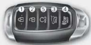
OLX2048003
- Door lock
- Door unlock
- Liftgate open
- Panic
- Remote start
If you press any button on the smart key during the Detect and Alert stage, the Smart Liftgate function will be deactivated.
Make sure to be aware of how to deactivate the Smart Liftgate function for emergency situations.
i Information
- If you press the door unlock button (2), the Smart Liftgate function will be deactivated temporarily. But, if you do not open any door for 30 seconds, the Smart Liftgate function will be activated again.
- If you press the liftgate open button (3) for more than 1 second, the liftgate opens.
- The Smart Liftgate function will still be activated if you press the door lock button (1) or liftgate open button (3) on the smart key as long as the Smart Liftgate is not already in the Detect and Alert stage.
- In case you have deactivated the Smart Liftgate function by pressing the smart key button and opened a door, the Smart Liftgate function can be activated again by closing and locking all doors.
Detecting area
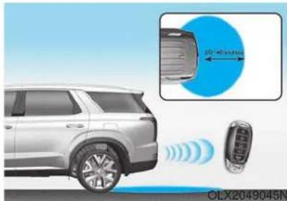
- The Smart Liftgate detecting area extends approximately 20-40 inches (50-100 cm) behind the vehicle. If you are positioned in the detecting area and are carrying the smart key, the hazard warning lights will blink and the chime will sound for about 3 seconds to alert you that the smart liftgate will open.
- The alert stops once the smart key is moved outside of the detecting area within the 3 second period.
i Information
- The Smart Liftgate function may not operate properly if any of the following instances occur:
- The smart key is close to a radio transmitter such as a radio station or an airport which can interfere with normal operation of the transmitter.
- The smart key is near a mobile two way radio system or a cellular phone.
- Another vehicle's smart key is being operated close to your vehicle.
• The Smart Liftgate detecting area may change when: - The vehicle is parked on an incline or slope
- One side of the vehicle is raised or lowered relative to the opposite side
Fuel Filler Door
Opening the fuel filler door
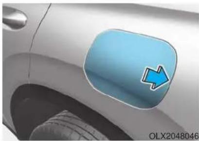
natural_image
Close-up of a car's side panel with a blue arrow icon on the cheek (no text or symbols)- Turn the engine off.
- Ensure the driver's door is unlocked.
- Push the fuel filler door near the 3 o'clock position.
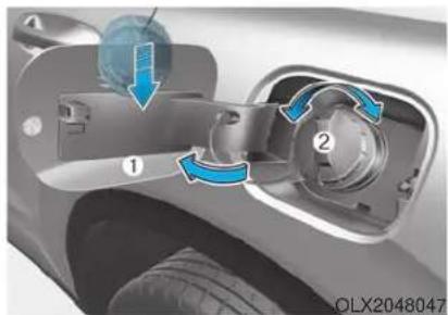
natural_image
Close-up of a car's internal components with blue arrows indicating motion, no visible text or symbols- Pull the fuel filler door (1) outward to access the fuel tank cap.
- To remove the fuel tank cap (2), turn it counterclockwise. You may hear a hissing noise as the pressure inside the tank equalizes.
- Place the cap on the fuel filler door.
i Information
If the fuel filler door does not open because ice has formed around it, tap lightly or push on the door to break the ice and release the door. Do not pry on the door. If necessary, spray around the door with an approved deicer fluid (do not use radiator anti-freeze) or move the vehicle to a warm place and allow the ice to melt.
Closing the fuel filler door
- To install the fuel tank cap, turn it clockwise until it "clicks" one time.
- Close the fuel filler door until it is latched securely.
i Information
The fuel filler door will not close if the driver's door is locked. If you lock the driver's door while fueling, unlock it before closing the fuel filler door.
i Information
- Tighten the cap until it clicks once, otherwise the fuel cap open warning indicator light will illuminate.
- There may be an intermittent noise near the refueling hole while the engine is idling if the fuel cap is not closed securely. This occurs normally with the OBD system.
- When refueling on unleveled ground, the fuel gauge may not point to the F position. It is not a malfunction. If you move your vehicle to a level ground, the fuel gauge will move to the full position.
WARNING
Gasoline is highly flammable and explosive. Failure to follow these guidelines may result in SERIOUS INJURY or DEATH:
- Read and follow all warnings posted at the gas station.
- Before refueling, note the location of the Emergency Gasoline Shut-Off, if available, at the gas station.
- Before touching the fuel nozzle, you should eliminate the potential build-up of static electricity by touching a metal part of the vehicle, a safe distance away from the fuel filler neck, nozzle, or other gas source, with your bare hand.
-
Do not use cellular phones while refueling. Electric current and/or electronic interference from cellular phones can potentially ignite fuel vapors and cause a fire.
-
Do not get back into a vehicle once you have begun refueling. You can generate a build-up of static electricity by touching, rubbing or sliding against any item or fabric capable of producing static electricity. Static electricity discharge can ignite fuel vapors causing a fire. If you must re-enter the vehicle, you should once again eliminate potentially dangerous static electricity discharge by touching a metal part of the vehicle, away from the fuel filler neck, nozzle or other gasoline source, with your bare hand.
- When using an approved portable fuel container, be sure to place the container on the ground prior to refueling. Static electricity discharge from the container can ignite fuel vapors causing a fire.
Once refueling has begun, contact between your bare hand and the vehicle should be maintained until the filling is complete.
- Use only approved portable plastic fuel containers designed to carry and store gasoline.
- When refueling, always move the shift button to the P (Park) position, set the parking brake, and place the ignition switch to the LOCK/OFF position. Sparks produced by electrical components related to the engine can ignite fuel vapors causing a fire.
-
Do not use matches or a lighter and do not smoke or leave a lit cigarette in your vehicle while at a gas station, especially during refueling.
-
Do not over-fill or top-off your vehicle tank, which can cause gasoline spillage.
- If a fire breaks out during refueling, leave the vicinity of the vehicle, and immediately contact the manager of the gas station and then contact the local fire department. Follow any safety instructions they provide.
- If pressurized fuel sprays out, it can cover your clothes or skin and thus subject you to the risk of fire and burns. Always remove the fuel cap carefully and slowly. If the cap is venting fuel or if you hear a hissing sound, wait until the condition stops before completely removing the cap.
• Always check that the fuel cap is installed securely to prevent fuel spillage in the event of an accident.
i Information
Make sure to refuel your vehicle according to the "Fuel Requirements" suggested in the Introduction chapter.
NOTICE
- Do not spill fuel on the exterior surfaces of the vehicle. Any type of fuel spilled on painted surfaces may damage the paint.
- If the fuel filler cap requires replacement, use only a genuine HYUNDAI cap or the equivalent specified for your vehicle. An incorrect fuel filler cap can result in a serious malfunction of the fuel system or emission control system.
INSTRUMENT CLUSTER
Type A
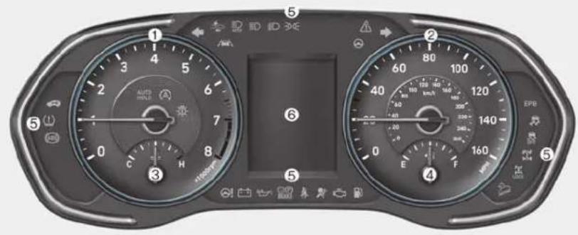
Type B
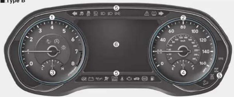
- Tachometer
- Speedometer
- Engine coolant temperature gauge
- Fuel gauge
- Warning and indicator lights
- LCD display (including Trip computer)
The actual cluster in the vehicle may differ from the illustration.
For more information, refer to the "Gauges and Meters" in this chapter.
OLX2049100N/OLX2049101N
Type C
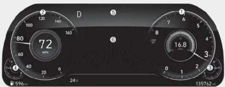
- Tachometer
- Speedometer
- Engine coolant temperature gauge
- Fuel gauge
- Warning and indicator lights
- LCD display (including Trip computer)
The actual cluster in the vehicle may differ from the illustration.
For more information, refer to the "Gauges and Meters" in this chapter.
OLX2049126N
Instrument Cluster Control
Adjusting instrument cluster illumination
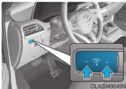
natural_image
Interior view of a car dashboard with a highlighted control panel and sensor icon (no readable text or symbols)When the vehicle's position lights or headlights are on, press the illumination control button to adjust the brightness of the instrument panel illumination.
When pressing the illumination control button, the interior switch illumination intensity is also adjusted.
WARNING
Never adjust the instrument cluster while driving. Doing so could lead to driver distraction which may cause an accident and lead to vehicle damage, serious injury, or death.
- The brightness of the instrument panel illumination is displayed.
- If the brightness reaches the maximum or minimum level, a chime will sound.
For information regarding the illumination setting on your audio display, refer to the "Setup" section of your Audio or Navigation manual.
Gauges and Meters
Speedometer
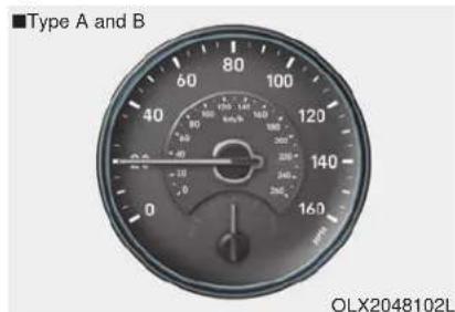
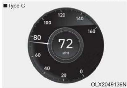
The speedometer indicates the speed of the vehicle and is calibrated in miles per hour (MPH) and/or kilometers per hour (km/h).
Tachometer
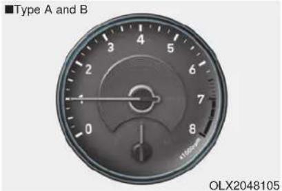
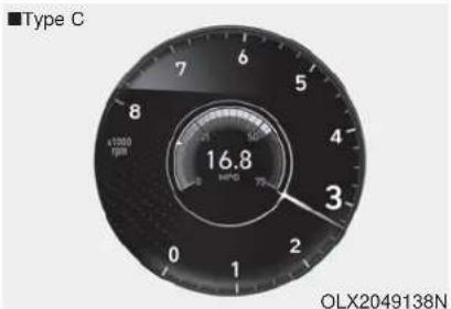
The tachometer indicates the approximate number of engine revolutions per minute (rpm).
NOTICE
Do not operate the engine within the tachometer's RED ZONE. This may cause severe engine damage.
Engine coolant temperature gauge
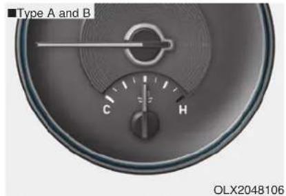
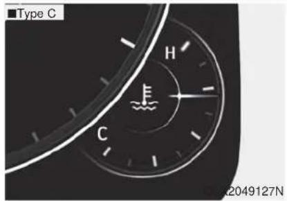
This gauge indicates the temperature of the engine coolant when the ignition switch is in the ON position.
NOTICE
If the gauge pointer moves beyond the normal range area toward the "H" position, it indicates overheating that may damage the engine.
Do not continue driving with an overheated engine. If your vehicle overheats, refer to "If the Engine Overheats" in chapter 6.
WARNING
Never remove the radiator cap or engine coolant reservoir cap when the engine is hot. The engine coolant is under pressure and could severely burn. Wait until the engine is cool before adding coolant to the reservoir.
Fuel gauge
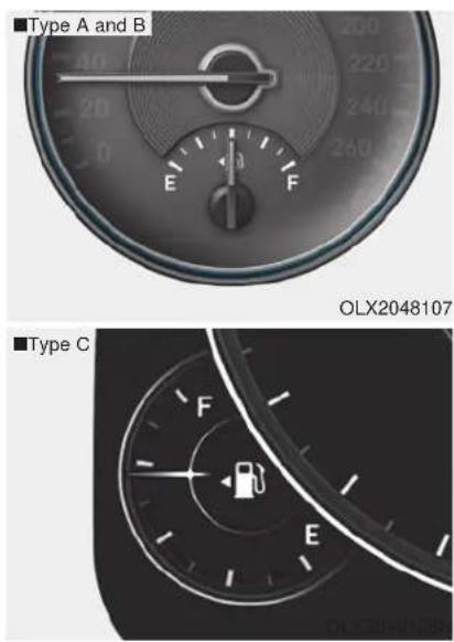
OLX2048107
This gauge indicates the approximate amount of fuel remaining in the fuel tank.
i Information
• The fuel tank capacity is given in chapter 8.
• The fuel gauge is supplemented by a low fuel warning light, which will illuminate when the fuel tank is nearly empty.
- On inclines or curves, the fuel gauge pointer may fluctuate or the low fuel warning light may come on earlier than usual due to the movement of fuel in the tank.
WARNING
Running out of fuel can expose vehicle occupants to danger.
You must stop and obtain additional fuel as soon as possible after the warning light comes on or when the gauge indicator comes close to the "E (Empty)" level.
NOTICE
Avoid driving with an extremely low fuel level. Running out of fuel could cause the engine to misfire damaging the catalytic converter.
Outside temperature gauge
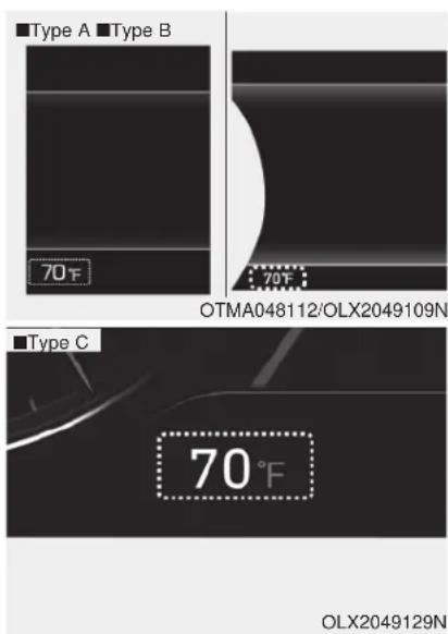
This gauge indicates the current outside air temperature by 1 degrees F (1 degrees C).
- Temperature range : -40°F \~ 140°F
(-40^ 60^)
Note that the temperature indicated on the LCD display may not change as quickly as the outside temperature (there may be a slight delay before the temperature changes.)
You can change the temperature unit from °F to °C or °C to °F in the User Settings mode in the cluster:
- Go to User Settings Mode → Other → Temperature Unit.
For vehicles equipped with Automatic Climate Control, you can also:
- Press the AUTO button while pressing the OFF button on the climate control unit for 3 seconds
Both the temperature unit on the cluster LCD display and climate control screen will change.
Odometer
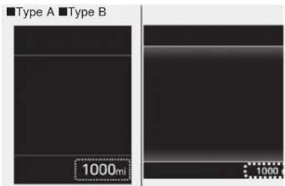
OTMA048183/OLX2049111N
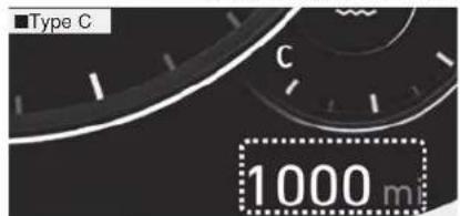
OLX2049131N
The odometer indicates the total distance that the vehicle has been driven and should be used to determine when periodic maintenance should be performed.
Range
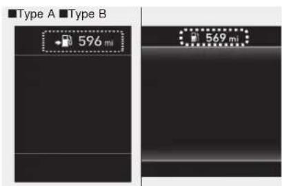
OPDE046138R/OLX2049112N
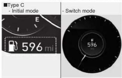
OLX2049130N/OLX2049132N
- The range is the estimated distance the vehicle can be driven with the remaining fuel.
- If the estimated distance is below 1 mi. (1 km), the trip computer will display "----" as range.
i Information
- If the vehicle is not on level ground or the battery power has been interrupted, the range function may not operate correctly.
- The range may differ from the actual driving distance as it is only an estimate of the available driving range for the vehicle and driving conditions.
- The trip computer may not register additional fuel if less than 1.6 gallon (6 liters) of fuel are added to the vehicle.
• The range may vary significantly based on driving conditions, driving habits, and condition of the vehicle.
Transmission Shift Indicator
Automatic transmission shift indicator
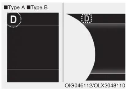
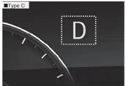
This indicator displays the gear position of the shift button.
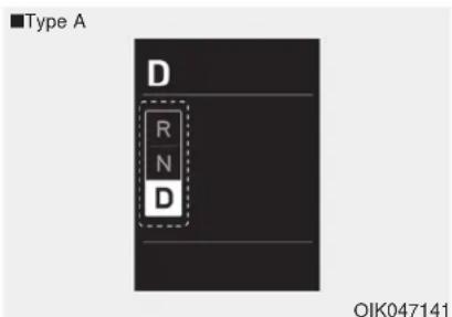
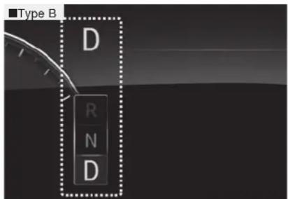
Shift indicator pop-up (if equipped)
The pop-up indicates the current gear position displayed in the cluster for about 2 seconds when shifting into other positions (P/R/N/D).
The shift indicator pop-up function can be activated or deactivated from the User Settings mode in the cluster LCD display.
Warning and Indicator Lights
i Information
Make sure that all warning lights are OFF after starting the engine. If any light is still ON, this indicates a situation that needs attention.
Seat Belt Warning Light

This warning light informs the driver that the seat belt is not fastened.
For more information, refer to "Seat Belts" in chapter 2.
Air Bag Warning Light

Parking Brake & Brake Fluid Warning Light

This warning light illuminates:
- When you set the ignition switch or the Engine Start/Stop button to the ON position.
- The air bag warning light illuminates for about 6 seconds and then turns off when all checks have been performed
- The air bag warning light will remain illuminated if there is a malfunction with the Safety Restraint System (SRS) air bag operation.
If this occurs, have the vehicle inspected by an authorized HYUNDAI dealer.
This warning light illuminates:
- When you set the ignition switch or the Engine Start/Stop button to the ON position.
- The parking brake light illuminates for about 3 seconds and will then turn off once the parking brake is released.
- Whenever the parking brake is applied.
- Whenever the brake fluid level in the reservoir is low.
- If the warning light illuminates with the parking brake released, it indicates the brake fluid level in the reservoir is low.
If the brake fluid level in the reservoir is low:
- Drive carefully to the nearest safe location and stop your vehicle.
- With the engine stopped, check the brake fluid level immediately and add fluid as required (For more details, refer to "Brake Fluid" in chapter 7). After adding brake fluid, check all brake components for fluid leaks. If a brake fluid leak is found, or if the warning light remains on, or if the brakes do not operate properly, do not drive the vehicle. Have the vehicle inspected by an authorized HYUNDAI dealer.
Dual-diagonal braking system
Your vehicle is equipped with dual-diagonal braking system. This means you still have braking on two wheels even if one of the dual systems should fail.
With only one of the dual systems working, more than normal pedal travel and greater pedal pressure is required to stop the vehicle.
Also, the vehicle will not stop in as short a distance with only a portion of the brake system working.
If the brakes fail while you are driving, shift to a lower gear for additional engine braking and stop the vehicle as soon as it is safe to do so.
WARNING
Parking Brake & Brake Fluid Warning Light
Driving the vehicle with a warning light ON is dangerous. If the Parking Brake & Brake Fluid Warning Light illuminates with the parking brake released, it indicates that the brake fluid level is low.
If this occurs, have the vehicle inspected by an authorized HYUNDAI dealer.
Anti-lock Brake System (ABS) Warning Light

This warning light illuminates:
- When you set the ignition switch or the Engine Start/Stop button to the ON position.
- The ABS warning light illuminates for about 3 seconds and then turns off.
- Whenever there is a malfunction with the ABS.
Note that the hydraulic braking system will still be operational even if there is a malfunction with the ABS.
Electronic Brake Force Distribution (EBD) System Warning Light


These two warning lights illuminate at the same time while driving:
- When the ABS and regular brake system may not work normally. If this occurs, have the vehicle inspected by an authorized HYUNDAI dealer.
WARNING
Electronic Brake Force Distribution (EBD) System Warning Light
When both ABS and Parking Brake & Brake Fluid Warning Lights are on, the brake system will not work normally and you may experience an unexpected and dangerous situation during sudden braking.
If this occurs, avoid high speed driving and abrupt braking.
Have the vehicle inspected by an authorized HYUNDAI dealer as soon as possible.
i Information - Electronic Brake Force Distribution (EBD) System Warning Light
When the ABS Warning Light is on or both ABS and Parking Brake & Brake Fluid Warning Lights are on, the speedometer, odometer, or tripmeter may not work. Also, the EPS Warning Light may illuminate and the steering effort may increase or decrease.
If this occurs, have the vehicle inspected by an authorized HYUNDAI dealer as soon as possible.
Electric Power Steering (EPS) Warning Light

This warning light illuminates:
- When the ignition is moved to ON, the warning light illuminates for about 3 seconds and turns off automatically if no problem.
- When the warning light illuminates while driving, it indicates that there is a problem with the electric power steering system. In this case, have the vehicle inspected by an authorized HYUNDAI dealer.
Malfunction Indicator Lamp (MIL)
This indicator light illuminates:
- When you set the ignition switch or the Engine Start/Stop button to the ON position.
- The malfunction indicator light illuminates for about 3 seconds and then goes off.
- Whenever there is a malfunction with either the emission control system or the engine or the vehicle powertrain.
If this occurs, have the vehicle inspected by an authorized HYUNDAI dealer.
NOTICE
Driving with the Malfunction Indicator Lamp (MIL) on may cause damage to the emission control system which could affect drivability and/or fuel economy.
NOTICE
If the Malfunction Indicator Lamp (MIL) illuminates, potential catalytic converter damage is possible which could result in loss of engine power.
If this occurs, have the vehicle inspected by an authorized HYUNDAI dealer as soon as possible.
Electronic Parking Brake (EPB) Warning Light
EPB
This warning light illuminates:
- When you set the ignition switch or the Engine Start/Stop button to the ON position.
- It illuminates for approximately 3 seconds and then goes off.
- When there is a malfunction with the EPB.
If this occurs, have the vehicle inspected by an authorized HYUNDAI dealer.
i Information
The Electronic Parking Brake (EPB) Warning Light may illuminate when the Electronic Stability control (ESC) Indicator Light comes on to indicate that the ESC is not working properly (This does not indicate malfunction of the EPB).
Charging System Warning Light
When this warning light illuminates while the engine is running, the battery is not being charged. Immediately turn OFF all electrical accessories. Try not to use electrically operated controls, such as the power windows. Keep the engine running.
Have the vehicle inspected by an authorized HYUNDAI dealer as soon as possible.

Engine Oil Pressure Warning Light
This warning light illuminates:
- When the engine oil pressure is low.
If the engine oil pressure is low:
- Drive carefully to the nearest safe location and stop your vehicle.
- Turn the engine off and check the engine oil level (For more details, refer to "Engine Oil" in chapter 7). If the level is low, add oil as required. If the warning light remains on after adding oil or if oil is not available, have the vehicle inspected by an authorized HYUNDAI dealer as soon as possible.

NOTICE
- If the engine does not stop immediately after the Engine Oil Pressure Warning Light is illuminated, severe damage could result.
-
If the warning light stays on while the engine is running, it indicates that there may be serious engine damage or malfunction. In this case:
-
Stop the vehicle as soon as it is safe to do so.
-
Turn off the engine and check the oil level. If the oil level is low, fill the engine oil to the proper level.
-
Start the engine again. If the warning light stays on after the engine is started, turn the engine off immediately. If this occurs, have the vehicle inspected by an authorized HYUNDAI dealer.
Low Fuel Level Warning Light

This warning light illuminates:
- When the fuel tank is nearly empty. Add fuel as soon as possible.
NOTICE
Driving with the Low Fuel Level warning light on or with the fuel level below "E" can cause the engine to misfire and damage the catalytic converter.
Washer Fluid Warning Light

This warning light illuminates:
- When the washer fluid level in the reservoir is nearly empty. If washer fluid warning light illuminates, refill the washer fluid reservoir in the engine room when possible.
Master Warning Light

This warning light illuminates:
- When there is a malfunction in operation in any of the following systems:
- LED headlamp malfunction (if equipped)
- Forward Collision-Avoidance Assist system malfunction (if equipped)
- Forward Collision-Avoidance Assist radar blocked (if equipped)
- Blind-Spot Collision Warning system malfunction (if equipped)
- Blind-Spot Collision Warning radar blocked (if equipped)
- Smart Cruise Control with Stop & Go malfunction (if equipped)
-
Smart Cruise Control with Stop & Go radar blocked (if equipped)
-
Lamp malfunction
- High Beam Assist malfunction (if equipped)
- Tire Pressure Monitoring System (TPMS) malfunction
To identify the details of the warning, look at the LCD display.
Low Tire Pressure Warning Light

This warning light illuminates:
- When you set the ignition switch or the Engine Start/Stop button to the ON position.
- It illuminates for approximately 3 seconds and then goes off.
- When one or more of your tires are significantly underinflated. (The location of the underinflated tires are displayed on the LCD display.)
For more details, refer to "Tire Pressure Monitoring System (TPMS)" in chapter 6.
This warning light remains ON after blinking for approximately 60 seconds, or repeatedly blinks ON and OFF in 3 second intervals:
- When there is a malfunction with the TPMS. If this occurs, have the vehicle inspected by an authorized HYUNDAI dealer as soon as possible.
For more details, refer to "Tire Pressure Monitoring System (TPMS)" in chapter 6.
WARNING
Safe Stopping
- The TPMS cannot alert you to severe and sudden tire damage caused by external factors.
- If you notice any vehicle instability, immediately take your foot off the accelerator pedal, apply the brakes gradually with light force, and slowly move to a safe position off the road.
All Wheel Drive (AWD) Warning Light (if equipped)

This warning light illuminates:
- When you set the ignition switch or the Engine Start/Stop button to the ON position.
- The All Wheel Drive warning light illuminates for about 3 seconds and then goes off.
- Whenever there is a malfunction with the AWD system.
If this occurs, have your vehicle inspected by an authorized HYUNDAI dealer.
Forward Collision-Avoidance Assist (FCA) System Warning Light
Lane Keeping Assist (LKA) System Indicator Light
LED Headlight Warning Light (if equipped)

This warning light illuminates:
- When you set the ignition switch or the Engine Start/Stop button to the ON position.
- It illuminates for approximately 3 seconds and then goes off.
- When there is a malfunction with the FCA.
If this occurs, have the vehicle inspected by an authorized HYUNDAI dealer.
For more details, refer to "Forward Collision-Avoidance Assist (FCA) system" in chapter 5.
This indicator light illuminates:
- [Green] When the system operating conditions are satisfied.
- [White] The system operating conditions are not satisfied.
- [Yellow] When there is a malfunction with the lane keeping assist system.
If this occurs, have your vehicle inspected by an authorized HYUNDAI dealer.
For more details, refer to "Lane Keeping Assist (LKA) system" in chapter 5.
This warning light illuminates:
- When you set the ignition switch or the Engine Start/Stop button to the ON position.
- When there is a malfunction with the LED headlight.
If this occurs, have the vehicle inspected by an authorized HYUNDAI dealer.
This warning light blinks:
When there is a malfunction with a LED headlight related part.
If this occurs, have the vehicle inspected by an authorized HYUNDAI dealer.
NOTICE
Continuous driving with the LED Headlight Warning Light on or blinking can reduce LED headlight life.
Icy Road Warning Light (if equipped)

AUTO STOP Indicator Light

Electronic Stability Control (ESC) Indicator Light

This warning light is to warn the driver the road may be icy.
When the temperature on the outside temperature gauge is approximately below 40^ F ( 4^ C), the Icy Road Warning Light and Outside Temperature Gauge blinks and then illuminates. Also, the warning chime sounds 1 time.
You can activate or deactivate Icy Road Warning function from the User Settings mode in the cluster LCD display.
i Information
If the icy road warning light appears while driving, you should drive more attentively and safely refraining from over-speeding, rapid acceleration, sudden braking or sharp turning, etc.
This indicator light illuminates:
- When the engine enters the Idle Stop mode of the ISG (Idle Stop and Go) system.
This indicator light blinks:
- When the automatic starting occurs, the AUTO STOP indicator on the cluster will blink for 5 seconds.
For more details, refer to the "ISG (Idle Stop and Go) system" in chapter 5.
i Information
When the engine automatically starts by the ISG system, some warning lights (ABS, ESC, ESC OFF, EPS or Parking brake warning light) may turn on for a few seconds.
This happens because of low battery voltage. It does not mean the system has malfunctioned.
This indicator light illuminates:
- When you set the ignition switch or the Engine Start/Stop button to the ON position.
- The Electronic Stability Control indicator light illuminates for about 3 seconds and then goes off.
- Whenever there is a malfunction with the ESC system.
If this occurs, have the vehicle inspected by an authorized HYUNDAI dealer.
This indicator light blinks:
- While the ESC is operating.
For more details, refer to "Electronic Stability Control (ESC)" in chapter 5.
Electronic Stability Control (ESC) OFF Indicator Light

OFF
Immobilizer Indicator Light (without smart key)(if equipped)
Immobilizer Indicator Light (with smart key (if equipped)
This indicator light illuminates:
- When you set the ignition switch or the Engine Start/Stop button to the ON position.
- It illuminates for approximately 3 seconds and then goes off.
- When you deactivate the ESC system by pressing the ESC OFF button.
For more details, refer to "Electronic Stability Control (ESC)" in chapter 5.
This indicator light illuminates:
- When the vehicle detects the immobilizer in the key with the ignition switch in the ON position.
- At this time, you can start the engine.
- The indicator light goes off after starting the engine.
This indicator light blinks:
- When there is a malfunction with the immobilizer system.
If this occurs, have the vehicle inspected by an authorized HYUNDAI dealer.
This indicator light illuminates for up to 30 seconds:
- When the vehicle detects the smart key in the vehicle with the Engine Start/Stop button in the ACC or ON position.
- Once the smart key is detected, you can start the engine.
- The indicator light goes off after starting the engine.
This indicator light blinks for a few seconds:
- When the smart key is not in the vehicle.
- If the smart key is not detected, you cannot start the engine.
This indicator light illuminates for 2 seconds and goes off:
- If the smart key is in the vehicle and the Engine Start/Stop button is ON, but the vehicle cannot detect the smart key.
If this occurs, have the vehicle inspected by an authorized HYUNDAI dealer.
This indicator light blinks:
- When there is a malfunction with the immobilizer system.
If this occurs, have the vehicle inspected by an authorized HYUNDAI dealer.
Turn Signal Indicator Light

This indicator light blinks:
- When you operate the turn signal indicator stalk.
If any of the following occur, there may be a malfunction with the turn signal system.
- The turn signal indicator light illuminates but does not blink
- The turn signal indicator light blinks rapidly
- The turn signal indicator light does not illuminate at all
If any of these conditions occur, have your vehicle inspected by an authorized HYUNDAI dealer.
High Beam Indicator Light

This indicator light illuminates:
- When the headlights are on and in the high beam position
- When the turn signal lever is pulled into the Flash-to-Pass position.
Light ON Indicator Light

This indicator light illuminates:
- When the tail lights or headlights are on.
High Beam Assist (HBA) indicator light (if equipped)

This indicator light illuminates :
- When the high-beam is on with the light switch in the AUTO light position.
- If your vehicle detects oncoming or preceding vehicles, the High Beam Assist (HBA) system will switch the high beam to low beam automatically.
For more details, refer to "High Beam Assist (HBA) system" in this chapter.
AUTO HOLD Indicator Light
AUTO HOLD
This indicator light illuminates:
- [White] When you activate the Auto Hold system by pressing the AUTO HOLD button.
- [Green] When you stop the vehicle completely by depressing the brake pedal with the Auto Hold system activated.
- [Yellow] When there is a malfunction with the Auto Hold system. If this occurs, have your vehicle inspected by an authorized HYUNDAI dealer.
For more details, refer to "Auto Hold" in chapter 5.
Cruise Indicator Light
CRUISE
This indicator light illuminates:
- When the cruise control system is enabled.
For more details, refer to "Cruise Control System" in chapter 5.
SPORT Mode Indicator Light (if equipped)
SPORT
This indicator light illuminates:
- When you select "SPORT" mode as drive mode.
For more details, refer to "Drive Mode Integrated Control System" in chapter 5.
SMART Mode Indicator Light (if equipped)
SMART
All Wheel Drive LOCK Indicator Light (if equipped)
Downhill Brake Control (DBC) Indicator Light (if equipped)

This indicator light illuminates:
- When you select "SMART" mode as drive mode.
For more details, refer to "Drive Mode Integrated Control System" in chapter 5.
This indicator light illuminates:
- When you set the ignition switch or the Engine Start/Stop button to the ON position.
- The AWD LOCK indicator light illuminates for about 3 seconds and then goes off.
- When you select AWD Lock mode by pressing the AWD LOCK button.
- The AWD LOCK mode is to transfer a portion of the drive torque to the rear wheels for increased traction on wet pavement, snow covered roads or when driving off road.

CAUTION
AWD Lock Mode
Do not use the AWD lock mode on dry paved roads. Doing so can cause abnormal noise or vibration, and may damage the AWD system.
This indicator light illuminates:
- When you set the ignition switch or the Engine Start/Stop button to the ON position.
- The Downhill Brake Control Indicator Light illuminates for about 3 seconds and then goes off.
- When you activate the system by pressing the DBC button.
This indicator light blinks:
- When the DBC is operating.
This indicator light illuminates yellow:
- When there is a malfunction with the DBC system.
If this occurs, have your vehicle inspected by an authorized HYUNDAI dealer.
For more details, refer to "Downhill Brake Control (DBC) System" in chapter 5.
LCD Display Messages
Shift to P or N to start engine (for smart key system)
This warning message is displayed if you try to start the engine with the shift button not in the P (Park) or N (Neutral) position.
i Information
You can start the engine with the shift button in the N (Neutral) position. But, for your safety, we recommend that you start the engine with the shift button in the P (Park) position.
Low key battery (for smart key system)
This warning message is displayed if the battery of the smart key is discharged while changing the Engine Start/Stop button to the OFF position.
Press brake pedal to start engine (for smart key system)
This warning message is displayed if the Engine Start/Stop button changes to the ACC position twice by pressing the button repeatedly without depressing the brake pedal.
You can start the vehicle by depressing the brake pedal and then pressing the Engine Start/Stop button.
Key not in vehicle (for smart key system)
This warning message is displayed if the smart key is not in the vehicle when you press the Engine Start/Stop button.
When attempting to start the vehicle, always have the smart key with you.
Key not detected (for smart key system)
This warning message is displayed if the smart key is not detected when you press the Engine Start/Stop button.
Press START button again (for smart key system)
This message is displayed if you were unable to start the vehicle when the Engine Start/Stop button was pressed.
If this occurs, attempt to start the engine by pressing the Engine Start/Stop button again.
If the warning message appears each time you press the Engine Start/Stop button, have your vehicle inspected by an authorized HYUNDAI dealer.
Press START button with key (for smart key system)
This warning message is displayed if you press the Engine Start/Stop button while the warning message "Key not detected" is displayed.
At this time, the immobilizer indicator light blinks.
Check BRAKE SWITCH fuse (for smart key system)
This warning message is displayed if the brake switch fuse is disconnected. You need to replace the fuse with a new one before starting the engine. If that is not possible, you can start the engine by pressing the Engine Start/Stop button for 10 seconds in the ACC position.
Battery discharging due to external electrical devices
This message is displayed if the battery voltage is weak due to any non-factory electrical accessories (ex. dashboard camera) while parking. Be careful that the battery is not discharged.
If the warning message appears after removing the non-factory electrical accessories, have the vehicle inspected by an authorized HYUNDAI dealer.
Door, Hood, Liftgate open indicator
OLX2048113
This warning is displayed if any door or the hood or the liftgate is left open. The warning will indicate which door is open in the display.
CAUTION
Before driving the vehicle, you should confirm that the door/ hood/liftgate is fully closed. Also, check there is no door/ hood/liftgate open warning light or message displayed on the instrument cluster.
Sunroof open indicator (if equipped)
natural_image
Top-down view of a car on a road with lane markings, no visible text or symbols
natural_image
Top-down view of a car inside a circular road, labeled 'Type C' in the top-left corner (no other text or symbols)This warning is displayed if you turn off the engine when the sunroof is open.
Close the sunroof securely before leaving your vehicle.
Window open indicator (if equipped)
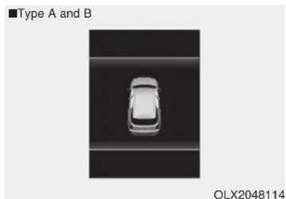
natural_image
Top-down view of a car with no visible text, numbers, or symbols on the vehicle itself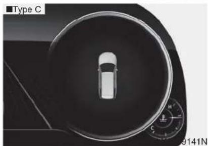
natural_image
Top-down view of a car's steering wheel and dashboard (no visible text or symbols)This warning is displayed if you turn off the engine when any window is open.
Low Pressure
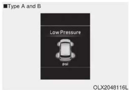
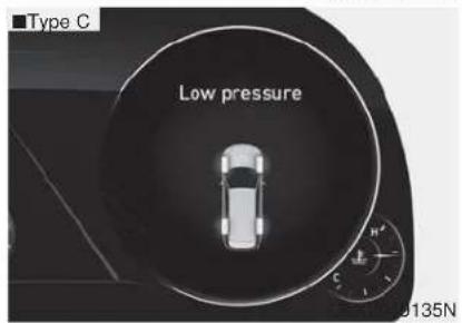
This warning message is displayed if the tire pressure is low. The corresponding tire on the vehicle will be illuminated.
For more details, refer to "Tire Pressure Monitoring System (TPMS)" in chapter 6.
Lights Mode
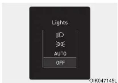
This indicator displays which exterior light is selected using the lighting control.
You can activate or deactivate Wiper/Lights Display function from the User Settings mode in the cluster LCD display.
Wiper
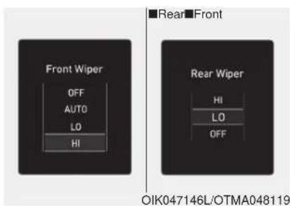
This indicator displays which wiper speed is selected using the wiper control.
You can activate or deactivate Wiper/Lights Display function from the User Settings mode in the cluster LCD display.
Heated Steering Wheel turned off (if equipped)
This message is displayed if you turn off the heated steering wheel.
For more details, refer to "Heated Steering Wheel" in this chapter.
Low washer fluid
This warning message is displayed if the washer fluid level in the reservoir is nearly empty.
Have the washer fluid reservoir refilled.
Low fuel
This warning message is displayed if the fuel tank is almost out of fuel.
When this message is displayed, the low fuel level warning light in the cluster will come on.
It is recommended to look for the nearest fueling station and refuel as soon as possible.
Add fuel as soon as possible.
Engine overheated
This warning message is displayed when the engine coolant temperature is above 248°F (120°C). This means that the engine is overheated and may be damaged.
If your vehicle is overheated, refer to "Overheating" in chapter 6.
Check headlight (if equipped)
This warning message is displayed if the headlights are not operating properly. A headlight bulb may need to be replaced.
i Information
Make sure to replace the burned out bulb with a new one of the same wattage rating.
Check turn signal (if equipped)
This warning message is displayed if the turn signal lamps are not operating properly. A lamp may need to be replaced.
i Information
Make sure to replace the burned out bulb with a new one of the same wattage rating.
Check High Beam Assist (HBA) system (if equipped)
This warning message is displayed if there is a problem with the High Beam Assist (HBA) system. Have the vehicle inspected by an authorized HYUNDAI dealer.
For more details, refer to "High Beam Assist (HBA) system" in chapter 3.
Check headlight LED (if equipped)
This warning message is displayed if there is a problem with the LED headlight. Have the vehicle inspected by an authorized HYUNDAI dealer.
Check Forward Collision-Avoidance Assist system (if equipped)
This warning message is displayed if there is a problem with the Forward Collision-Avoidance Assist (FCA) system. Have the vehicle inspected by an authorized HYUNDAI dealer.
For more details, refer to "Forward Collision-Avoidance Assist (FCA) system" in chapter 5.
Check Blind-Spot Collision Warning (BCW) system (if equipped)
This warning message is displayed if there is a problem with the Blind-Spot Collision Warning system. Have the vehicle inspected by an authorized HYUNDAI dealer.
For more details, refer to "Blind-Spot Collision Warning (BCW)/Blind-Spot Collision-Avoidance Assist (BCA)" or "Rear Cross-Traffic Collision Warning (RCCW)/Rear Cross-Traffic Collision-Avoidance Assist (RCCA)" System in chapter 5.
Check Smart Cruise Control System (if equipped)
This warning message is displayed if there is a problem with the Smart Cruise Control system. Have the vehicle inspected by an authorized HYUNDAI dealer.
For more details, refer to "Smart Cruise Control with Stop & Go" in chapter 5.
Check Driver Attention Warning (DAW) system (if equipped)
This warning message is displayed if there is a problem with the Driver Attention Warning (DAW). Have the vehicle inspected by an authorized HYUNDAI dealer.
For more details, refer to "Driver Attention Warning (DAW)" in chapter 5.
Check Lane Keeping Assist (LKA) system (if equipped)
This warning message is displayed if there is a problem with the Check Lane Keeping Assist (LKA) system. Have the vehicle inspected by an authorized HYUNDAI dealer.
For more details, refer to "Check Lane Keeping Assist (LKA) system" in chapter 5.
LCD DISPLAY (CLUSTER TYPE A AND TYPE B)
LCD Display Control
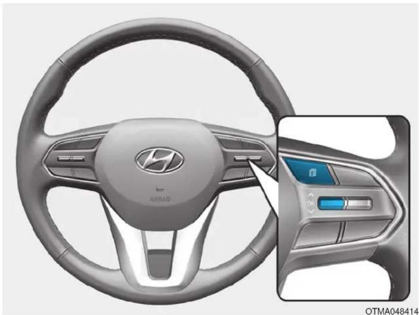
natural_image
Interior view of a car steering wheel with ABBAS logo and control panel (no text or symbols on the main body)The LCD display modes can be changed by using the control buttons.
(1): MODE button for changing modes
(2) ∧ ∨ : MOVE switch for changing items
(3) OK : SELECT/RESET button for setting or resetting the selected item
LCD Display Modes
| Modes Symbol Explanation | ||
| Trip Computer |  | The Trip Computer mode displays driving information such as the tripmeter, fuel economy, etc. For details, refer to "Trip Computer" in this chapter. |
| Turn By Turn (TBT) (if equipped) |  | This mode displays the state of the navigation. |
| Assist |  | The Driver Assist mode displays the status of the following features:- Smart Cruise Control (SCC) system- Lane Keeping Assist (LKA) system- Driver Attention Warning (DAW) system- Tire pressure- Traction force distribution status of front-wheels and rear-wheelsFor more information, refer to "Smart Cruise Control with Stop & Go)", "Lane Keeping Assist (LKA) system", "Driver Attention Warning (DAW) system", "Traction force distribution status of front-wheels and rear-wheels" in chapter 5 and "Tire Pressure Monitoring System (TPMS)" in chapter 6. |
| User Settings |  | The User Settings mode provides user options for a variety of settings including door lock/unlock features, convenience features, driver assistance settings, etc. |
| Master Warning |  | The Master Warning mode displays warning messages related to the vehicle when one or more systems is not operating normally. |
The information provided may differ depending on which functions are applicable to your vehicle.
Trip computer mode
OIK047124N OIK047147N OLX2049119N
Turn By Turn (TBT) mode
The trip computer mode displays information related to vehicle driving parameters including fuel economy, tripmeter information and vehicle speed.
For more details, refer to "Trip Computer" in this chapter.
This mode displays the state of the navigation.
Assist mode
SCC/LKA/DAW
This mode displays the state of the Smart Cruise Control (SCC), Lane Keeping Assist (LKA) and Driver Attention Warning (DAW).
For more details, refer to each system information in chapter 5.
OLX2048120L OLX2048121
Tire Pressure
This mode displays information related to Tire Pressure.
For more details, refer to "Tire Pressure Monitoring System (TPMS)" in chapter 6.
Driving force distribution (AWD)
This mode displays information related to AWD driving force.
For more details, refer to the "All Wheel Drive" in the chapter 5.
Master warning mode
This warning light informs the driver the following situations.
- LED headlamp malfunction (if equipped)
- Forward Collision-Avoidance Assist system malfunction (if equipped)
- Forward Collision-Avoidance Assist radar blocked (if equipped)
- Blind-Spot Collision Warning system malfunction (if equipped)
- Blind-Spot Collision Warning radar blocked (if equipped)
- Smart Cruise Control with Stop & Go malfunction (if equipped)
- Smart Cruise Control with Stop & Go radar blocked (if equipped)
- Lamp malfunction
- High Beam Assist malfunction (if equipped)
- Tire Pressure Monitoring System (TPMS) malfunction
The Master Warning Light illuminates if one or more of the above warning situations occur. At this time, the LCD Modes Icon will change from (☐o ( ).
If the warning situation is solved, the master warning light will be turned off and the LCD Modes Icon will be changed back to its previous icon (💡).
User settings mode
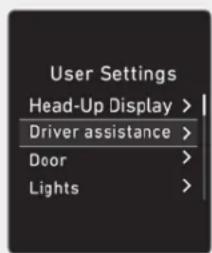
OIK047148L
In this mode, you can change the settings of the instrument cluster, doors, lamps, etc.
- Head-up display
- Driver Assistance
- Door
- Lights
- Sound
- Convenience
- Service interval
- Other
- Language
- Reset
The information provided may differ depending on which functions are applicable to your vehicle.
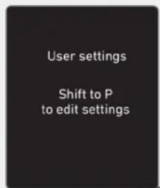
OOSEV048172L
Shift to P to edit settings
This warning message appears if you try to adjust the User Settings while driving.
For your safety, change the User Settings after parking the vehicle, applying the parking brake and shifting to P (Park).
Quick guide help
This mode provides quick guides for the systems in the User Settings mode.
Select an item, press and hold the OK button.
For more details, about each system, refer to this Owner's Manual.
- Head-Up Display
| Items Explanation | |
| Enable Head-Up Display To activate or deactivate the Head-up display function. | |
| Display Height To adjust the height of the image displayed | |
| Rotation To adjust the angle of the image displayed. | |
| Brightness To adjust the brightness of the image displayed. | |
| Content Selection | To select the content to be displayed.- Tum by Tum- Traffic Information- Cruise control- Lane keeping assist- Blind-spot Collision Warning |
| Speed Size | To select the speedometer size displayed.- Large/Medium/Small |
| Speed Color | To select the speedometer color displayed.- White/Orange/Green |
For more information, refer to "Head-Up Display" in this chapter.
* The information provided may differ depending on which functions are applicable to your vehicle.
- Driver Assistance
| Items Explanation | |
| SCC Reaction | • Fast / Normal / SlowTo adjust the sensitivity of the Smart Cruise Control system.For more details, refer to "Smart Cruise Control with Stop & Go" in chapter 5. |
| Driving assist | • Leading vehicle departure alertTo activate or deactivate the Leading vehicle departure alert.For more details, refer to the "Leading vehicle departure alert" in chapter 5. |
| • Lane Following AssistTo activate or deactivate the Lane Following Assist (LFA) system.For more details, refer to the "Lane Following Assist (LFA) System" in chapter 5. | |
| • Highway Driving AssistTo activate or deactivate the Highway Driving Assist (HDA) system.For more details, refer to the "Highway Driving Assist (HDA) System" in chapter 5. | |
| Warning Timing | • Normal / LaterTo select when to provide a warning for all driver assistance. |
| Warning Volume | • High / Medium / LowTo adjust the warning sound volume of all driver assistance. |
| Driver Attention Warning | To activate or deactivate the Driver Attention Warning (DAW).For more information, refer to the "Driver Attention Warning (DAW)" in chapter 5. |
- Driver Assistance
| Items Explanation | |
| Forward Safety | Active Assist: If selected, the system controls the vehicle and provides a warning when a collision is detected.Warning Only: If selected, the system provides a warning when a collision is detected.Off: Deactivates the system.For more details, refer to the "Forward Collision-Avoidance Assist system" in chapter 5. |
| Lane Safety | To adjust the Lane Keeping Assist (LKA) function.- Lane Keeping Assist- Lane Departure Warning- OffFor more details, refer to the "Lane Keeping Assist (LKA) system" in chapter 5. |
| Blind-Spot Safety | Blind-Spot ViewTo activate or deactivate the Blind-Spot View.For more details, refer to the "Blind-Spot View" in this chapter. |
| SEA(Safe Exit Assistance)To activate or deactivate the Safe Exit Assistance.For more details, refer to the "Safe Exit Assistance" in chapter 5. | |
| Active assistWarning onlyOffFor more details, refer to "Blind-spot Collision-Avoidance Assist (BCA)" in chapter 5. |
* The information provided may differ depending on which functions are applicable to your vehicle.
- Driver Assistance
| Items Explanation | |
| Parking Safety | • Rear Cross-Traffic SafetyTo activate or deactivate the Rear Cross-Traffic Collision Warning function.For more details, refer to the "Rear Cross-traffic Collision Warning (RCCW) / Rear Cross-traffic Collision-Avoidance Assist (RCCA)" in chapter 5. |
- Door
| Items Explanation | |
| Automatically Lock | Enable on speed: All doors will be automatically locked when the vehicle speed exceeds 9.3 mph (15 km/h).Enable on shift: All doors will be automatically locked if the vehicle is shifted from the P (Park) position to the R (Reverse), N (Neutral), or D (Drive) position. |
| Automatically Unlock | Disable : The auto door unlock operation will be canceled.On key out : All doors will be automatically unlocked when the ignition key is removed from the key ignition switch (if equipped with remote key).Vehicle off : All doors will be automatically unlocked when the Engine Start/Stop button is set to the OFF position. (if equipped with smart key)On shift to P : All doors will be automatically unlocked if the automatic transmission is shifted to the P (Park) position. |
- Door
| Items Explanation | |
| Two Press Unlock | Off: The two press unlock function will be deactivated. Therefore, all doors will unlock if the door unlock button is pressed.On: Only the driver's door will unlock if the door unlock button is pressed. When the door unlock button is pressed again within 4 seconds, the remaining doors will unlock. |
| Horn Feedback | To activate or deactivate the horn feedback.If the horn feedback is activated, after locking the door by pressing the lock button on the remote key, and pressing it again within 4 seconds, the horn feedback sound will operate once to indicate that all doors are locked (if equipped with remote key). |
| Power Liftgate | To activate or deactivate the Power Liftgate system.For more details, refer to "Power Liftgate" in this chapter. |
| Power Liftgate Speed | Fast / NormalTo select the speed of the power liftgate opening and closingFor more details, refer to "Power Liftgate" in this chapter. |
| Smart Liftgate | To activate or deactivate the Smart Liftgate system.For more details, refer to "Smart Liftgate" in this chapter. |
* The information provided may differ depending on which functions are applicable to your vehicle.
4. Lights
| Items Explanation | |
| One Touch Turn Signal | Off: The one touch turn signal function will be deactivated.3, 5, 7 Flashes: The turn signal indicator will blink 3, 5, or 7 times when the turn signal lever is moved slightly.For more details, refer to "Lighting" in this chapter. |
| Headlight Delay | To activate or deactivate the headlight delay function.For more details, refer to "Lighting" in this chapter. |
* The information provided may differ depending on which functions are applicable to your vehicle.
5. Sound
| Items Explanation | |
| Welcome Sound To activate or deactivate the welcome sound function. | |
* The information provided may differ depending on which functions are applicable to your vehicle.
6. Convenience
| Items Explanation | |
| Seat Slide Easy Access | Off: The seat easy access function is deactivated.Normal/Extended: When you turn off the engine, the driver's seat will automatically move rearward short (Normal) or long (Extended) for you to enter or exit the vehicle more comfortably.For more details, refer to "Driver Position Memory System" in this chapter. |
- Convenience
| Items Explanation | |
| Seat Height Easy Access | To activate or deactivate the Seat Height Easy Access.For more details, refer to "Driver Position Memory System" in this chapter. |
| Rear Occupant Alert | To activate or deactivate the Rear Occupant AlertFor more details, refer to "Rear Occupant Alert (ROA) system" in this chapter. |
| Welcome Light | • On driver approach: The welcome light turns on automatically when the vehicle is approached with the smart key.For more details, refer to "Welcome System" in this chapter. |
| Wireless Charging System | To activate or deactivate the wireless charging system in the front seat.For more details, refer to "Wireless Charging System" in this chapter. |
| Traffic Information | To activate or deactivate traffic information display function.When activated, traffic information, such as speed limits, etc. are displayed in the cluster LCD display. |
| Wiper/Lights Display | To activate or deactivate the Wiper/Light mode.When activated, the LCD display shows the selected Wiper/Light mode whenever you change the mode. |
| Auto Rear Wiper (in R) | To activate or deactivate the rear wiper while the vehicle is in reverse with the front wiper ON. |
| Gear Position Pop-up | To activate or deactivate the gear position pop-up.When activated, the gear position will be displayed in the cluster LCD display. |
| Icy Road Warning To activate or deactivate the | Icy Road Warning function. |
* The information provided may differ depending on which functions are applicable to your vehicle.
7. Service interval
| Items Explanation | |
| Service Interval To activate or deactivate the service interval function. | |
| Adjust Interval If the service interval menu is activated, you may adjust the time and distance. | |
If the service interval is activated and the time and distance is adjusted, messages are displayed in the following situations each time the vehicle is turned on.
- Service in: Displayed to inform the driver the remaining mileage and days to service.
- Service required: Displayed when the mileage and days to service has been reached or passed.
i Information
If any of the following conditions occur, the mileage and number of days to service may be incorrect.
- The battery cable is disconnected.
- The fuse switch is turned off.
-
The battery is discharged.
-
Other
| Items Explanation | |
| Fuel Economy Reset | Off: The average fuel economy will not reset automatically whenever refueling.After ignition: When the engine has been OFF for 4 hours or longer the average fuel economy will reset automatically.After refueling: The average fuel economy will reset automatically after adding 1.6 gallons (6 liters) of fuel or more and after driving speed exceeds 1 mph (1 km/h).For more details, refer to "Trip Computer" in this chapter. |
| Fuel Economy Unit | US gallon / UK gallonTo select the fuel economy unit. |
| Temperature Unit | °C / °FTo select the temperature unit. |
| Tire Pressure Unit | psi / kPa / barTo select the tire pressure unit. |
- Language
| Items Explanation | |
| Language To select language. |
- Reset
| Items Explanation | |
| Reset | You can reset the menus in the User Settings mode. All menus in the User Settings mode are reset to factory settings, except language and service interval. |
* The information provided may differ depending on which functions are applicable to your vehicle.
TRIP COMPUTER (CLUSTER TYPE A AND TYPE B)
The trip computer is a microcomputer-controlled driver information system that displays information related to driving.
i Information
Some driving information stored in the trip computer (for example Average Vehicle Speed) resets if the battery is disconnected.
Trip modes
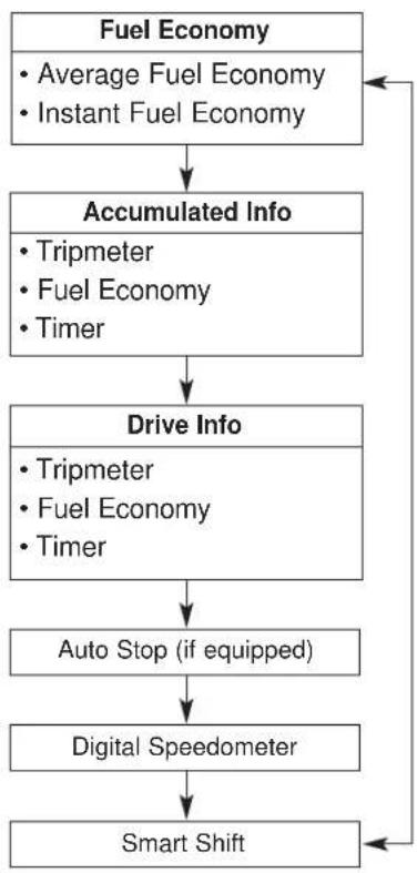
flowchart
graph TD
    A["Fuel Economy\n• Average Fuel Economy\n• Instant Fuel Economy"] --> B["Accumulated Info\n• Tripmeter\n• Fuel Economy\n• Timer"]
    B --> C["Drive Info\n• Tripmeter\n• Fuel Economy\n• Timer"]
    C --> D["Auto Stop (if equipped)"]
    D --> E["Digital Speedometer"]
    E --> F["Smart Shift"]
    F --> A
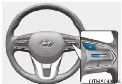
natural_image
Interior view of a car steering wheel with a highlighted control panel (no text or symbols visible)To change the trip mode, toggle the "^," switch on the steering wheel.
Average fuel economy/Instant fuel economy
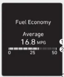
bar
Fuel Economy | Category | Value (MPG) | |---|---| | Average | 16.8 | | 0-25 | 0 | | 25-50 | 25 | | 50-100 | 50 | COIK047124N
Average Fuel Economy (1)
- The average fuel economy is calculated by the total driving distance and fuel consumption since the last average fuel economy reset.
- The average fuel economy can be reset both manually and automatically.
Manual reset
To clear the average fuel economy manually, press the OK button on the steering wheel for more than 1 second when the average fuel economy is displayed.
Automatic reset
To automatically reset the average fuel economy, select between "After Ignition" or "After Refueling" in the User Settings mode in the cluster LCD display.
- After ignition: When the engine has been OFF for 4 hours or longer the average fuel economy will reset automatically.
- After refueling: The average fuel economy will reset automatically after adding 1.6 gallons (6 liters) of fuel or more and after driving speed exceeds 1 mph (1 km/h).
i Information
The vehicle must be driven for a minimum of 0.19 miles (300 meters) since the last ignition key cycle before the average fuel economy will be recalculated.
Instant Fuel Economy (2)
- The instantaneous fuel economy is displayed according to the bar graph in the LCD display while driving.
Accumulated Info display
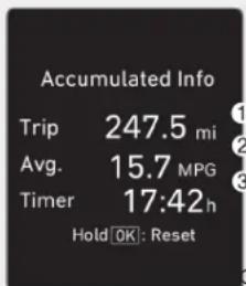
OIK047174N OIK047176N
The accumulated driving information will continue to be counted while the engine is still running (for example, when the vehicle is in traffic or stopped at a stop light).
i Information
The vehicle must be driven for a minimum of 0.19 miles (300 meters) since the last ignition key cycle before the average fuel economy will be recalcu-
This display shows the accumulated trip distance (1), the average fuel economy (2), and the total driving time (3).
The information is accumulated starting from the last reset.
To reset the details, press and hold the OK button when viewing the Accumulated driving info. The trip distance, the average fuel economy, and total driving time will reset simultaneously.
Drive Info display
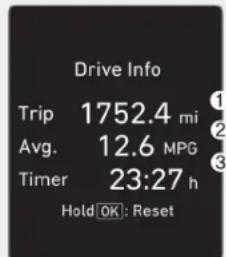
This display shows the trip distance (1), the average fuel economy (2), and the total driving time (3).
The information is combined for each ignition cycle. However, when the engine has been OFF for 4 hours or longer the Drive Info screen will reset.
To reset the details, press and hold the OK button when viewing the Drive Info. The trip distance, the average fuel economy, and total driving time will reset simultaneously.
The driving information will continue to be counted while the engine is still running (for example, when the vehicle is in traffic or stopped at a stop light).

Information
The vehicle must be driven for a minimum of 0.19 miles (300 meters) since the last ignition key cycle before the average fuel economy will be recalculated.
Digital speedometer
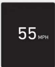
OIK047151N OIK047179N
This digital speedometer display shows the speed of the vehicle.
Smart shift
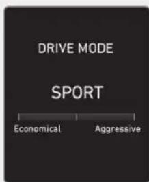
This mode displays the currently selected drive mode.
For more details, refer to "Drive Mode Integrated Control System" in chapter 5.
LCD DISPLAY (CLUSTER TYPE C) (IF EQUIPPED)
LCD Display Control
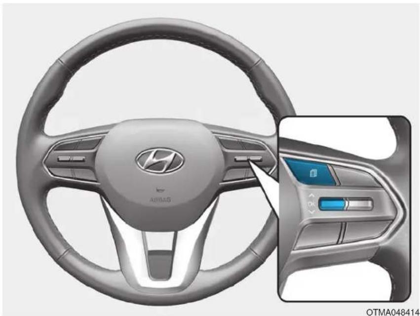
natural_image
Interior view of a car steering wheel with ABBAS logo and control panel (no text or symbols on the main body)The LCD display modes can be changed by using the control buttons.
(1): MODE button for changing modes
(2) ∧ ∨ : MOVE switch for changing items
(3) OK
- Tab: SELECT/RESET button for setting the selected item
- Tab and hold: SELECT/RESET button for retrieving assist information or resetting the selected item
View Modes
| Modes Explanation | |
| Utility | The Trip Computer mode displays driving information such as the trip distance, fuel economy and etc. For details, refer to "Trip Computer" In this chapter. |
| Driving Assist The Driving Assist mode displays the driving status. | |
| Turn By Turn (TBT) (if equipped) | This mode displays the state of the navigation. |
| Parking Assist The Parking Assist mode displays the parking status. | |
| Driving Info. Display for 4 seconds when the vehicle mode changes from IGN ON to OFF | |
The information provided may differ depending on which functions are applicable to your vehicle.
Utility View Mode
The utility view mode displays information related to vehicle driving parameters including fuel economy and trip distance information.
Utility Items
The utility items appear as well in trip computer mode, driving assist mode and turn by turn mode.
The information provided may differ depending on which functions are applicable to your vehicle.
• Fuel Economy Information
The average fuel economy and instant fuel economy are displayed.
- Manual reset: Press and hold OK button to initialize set up
- Automatic reset: Automatically reset the average fuel economy when the set-up conditions are satisfied in User Settings menu.
- Driving Information
The trip distance for each ignition cycle, fuel economy (undisplayed item in fuel economy: driving speed), trip time are shown. Press and hold OK button to initialize set up. When the engine has been OFF for 4 hours or longer the average fuel economy will reset automatically.
• Information after Refueling
The vehicle information such as trip distance, fuel economy (undisplayed item in fuel economy: driving speed) and trip time is displayed after refueling. Press and hold OK button to initialize set up.
• Accumulated Information
The vehicle information such as trip distance, fuel economy (undisplayed item in fuel economy: driving speed) and trip time is displayed after manual initialization.
• Digital Speed Display
It shows current vehicle speed.
- AUTO STOP
The cumulative time is show when the engine is off. Press and hold OK button to initialize set up.
- Driver Attention Warning
Display the status of the Driver Attention Warning system. When the engine is off or the vehicle comes to a stop, the system is reset. Press and hold OK button to initialize set up.
- Smart Shift
- Tire Pressure
- Digital RPM
Driving Assist View Mode
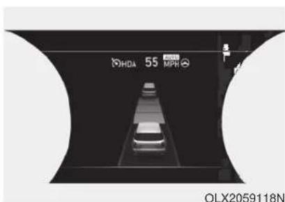
TBT (Turn By Turn) Mode
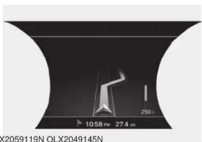
SCC/LKA/HAD/FCA
This mode displays the state of the Smart Cruise Control (SCC) and Lane Keeping Assist (LKA).
For more details, refer to system information in chapter 5.
It shows the information by interworking with the navigation.
Parking Assist View Mode
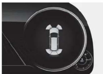
natural_image
Top-down view of a car's dashboard with a circular dial indicator (no text or symbols)It displays the information related to the parking assist system movement.
Other Information Display
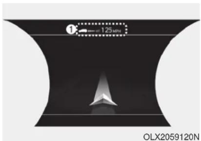
Driving information summary (1)
The current operation conditions of the Cruise Control mode, Smart Cruise Control and high speed driving assist modes. It does not show such information while driving assist mode is working.
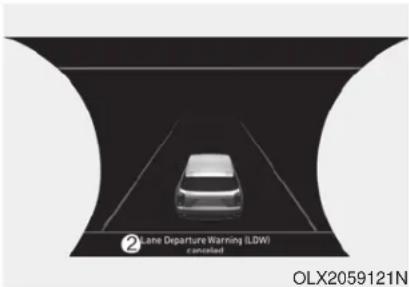
Driving information summary (2)
- It shows the weather and fine dust concentration. (If equipped)
- While interworking with the navigation, it displays the distance to the destinations or stops, the time to destinations or stops and the estimated time of arrival.
- Assist messages appear while set up.
OPTION MENU (CLUSTER TYPE C)
WARNING
While driving, please do not change the setting mode. It may distract your attention and cause the accident.
NOTICE
Displayed items of user's setting may differ from the content in this owner's manual since the contents vary with the vehicle's technical specifications.
| List Set-up messages | |
| Service Interval | Check the service message |
| Head-up Display | To activate or deactivate head-up displaySet up the height, rotation and brightness (if equipped) |
| Warning Timing | Normal/LaterTo select when to provide a warning for all driver assistance |
User settings mode
In this mode, you can change the settings of the instrument cluster, doors, lamps, etc.
- Head-up display
- Driver Assistance
- Door
- Lights
- Sound
- Convenience
- Service interval
- Other
- Language
- Reset
The information provided may differ depending on which functions are applicable to your vehicle.
Shift to P to edit settings
This warning message appears if you try to adjust the User Settings while driving.
For your safety, change the User Settings after parking the vehicle, applying the parking brake and shifting to P (Park).
Quick guide help
This mode provides quick guides for the systems in the User Settings mode.
Select an item, press and hold the OK button.
For more details, about each system, refer to this Owner's Manual.
- Head-Up Display
| Items Explanation | |
| Enable Head-Up Display To activate or deactivate the Head-up display function. | |
| Display Height To adjust the height of the image displayed | |
| Rotation To adjust the angle of the image displayed. | |
| Brightness To adjust the brightness of the image displayed. | |
| Content Selection | To select the content to be displayed.- Tum by Tum- Traffic Information- Cruise control- Lane keeping assist- Blind-spot Collision Warning |
| Speed Size | To select the speedometer size displayed.- Large/Medium/Small |
| Speed Color | To select the speedometer color displayed.- White/Orange/Green |
For more information, refer to "Head-Up Display" in this chapter.
* The information provided may differ depending on which functions are applicable to your vehicle.
- Driver Assistance
| Items Explanation | |
| SCC Reaction | • Fast / Normal / SlowTo adjust the sensitivity of the Smart Cruise Control system.For more details, refer to "Smart Cruise Control with Stop & Go" in chapter 5. |
| Driving assist | • Leading vehicle departure alertTo activate or deactivate the Leading vehicle departure alert.For more details, refer to the "Leading vehicle departure alert" in chapter 5. |
| • Lane Following AssistTo activate or deactivate the Lane Following Assist (LFA) system.For more details, refer to the "Lane Following Assist (LFA) System" in chapter 5. | |
| • Highway Driving AssistTo activate or deactivate the Highway Driving Assist (HDA) system.For more details, refer to the "Highway Driving Assist (HDA) System" in chapter 5. | |
| Warning Timing | • Normal / LaterTo select when to provide a warning for all driver assistance. |
| Warning Volume | • High / Medium / LowTo adjust the warning sound volume of all driver assistance. |
| Driver Attention Warning | To activate or deactivate the Driver Attention Warning (DAW).For more information, refer to the "Driver Attention Warning (DAW)" in chapter 5. |
- Driver Assistance
| Items Explanation | |
| Forward Safety | Active Assist: If selected, the system controls the vehicle and provides a warning when a collision is detected.Warning Only: If selected, the system provides a warning when a collision is detected.Off: Deactivates the system.For more details, refer to the "Forward Collision-Avoidance Assist system" in chapter 5. |
| Lane Safety | To adjust the Lane Keeping Assist (LKA) function.- Lane Keeping Assist- Lane Departure Warning- OffFor more details, refer to the "Lane Keeping Assist (LKA) system" in chapter 5. |
| Blind-Spot Safety | Blind-Spot ViewTo activate or deactivate the Blind-Spot View.For more details, refer to the "Blind-Spot View" in this chapter. |
| SEA(Safe Exit Assistance)To activate or deactivate the Safe Exit Assistance.For more details, refer to the "Safe Exit Assistance" in chapter 5. | |
| Active assistWarning onlyOffFor more details, refer to "Blind-spot Collision-Avoidance Assist (BCA)" in chapter 5. |
* The information provided may differ depending on which functions are applicable to your vehicle.
- Driver Assistance
| Items Explanation | |
| Parking Safety | • Rear Cross-Traffic SafetyTo activate or deactivate the Rear Cross-Traffic Collision Warning function.For more details, refer to the "Rear Cross-traffic Collision Warning (RCCW) / Rear Cross-traffic Collision-Avoidance Assist (RCCA)" in chapter 5. |
- Door
| Items Explanation | |
| Automatically Lock | Enable on speed: All doors will be automatically locked when the vehicle speed exceeds 9.3 mph (15 km/h).Enable on shift: All doors will be automatically locked if the vehicle is shifted from the P (Park) position to the R (Reverse), N (Neutral), or D (Drive) position. |
| Automatically Unlock | Disable : The auto door unlock operation will be canceled.On key out : All doors will be automatically unlocked when the ignition key is removed from the key ignition switch (if equipped with remote key).Vehicle off : All doors will be automatically unlocked when the Engine Start/Stop button is set to the OFF position. (if equipped with smart key)On shift to P : All doors will be automatically unlocked if the automatic transmission is shifted to the P (Park) position. |
- Door
| Items Explanation | |
| Two Press Unlock | Off: The two press unlock function will be deactivated. Therefore, all doors will unlock if the door unlock button is pressed.On: Only the driver's door will unlock if the door unlock button is pressed. When the door unlock button is pressed again within 4 seconds, the remaining doors will unlock. |
| Horn Feedback | To activate or deactivate the horn feedback.If the horn feedback is activated, after locking the door by pressing the lock button on the remote key, and pressing it again within 4 seconds, the horn feedback sound will operate once to indicate that all doors are locked (if equipped with remote key). |
| Power Liftgate | To activate or deactivate the Power Liftgate system.For more details, refer to "Power Liftgate" in this chapter. |
| Power Liftgate Speed | Fast / NormalTo select the speed of the power liftgate opening and closingFor more details, refer to "Power Liftgate" in this chapter. |
| Smart Liftgate | To activate or deactivate the Smart Liftgate system.For more details, refer to "Smart Liftgate" in this chapter. |
* The information provided may differ depending on which functions are applicable to your vehicle.
4. Lights
| Items Explanation | |
| One Touch Turn Signal | Off: The one touch turn signal function will be deactivated.3, 5, 7 Flashes: The turn signal indicator will blink 3, 5, or 7 times when the turn signal lever is moved slightly.For more details, refer to "Lighting" in this chapter. |
| Headlight Delay | To activate or deactivate the headlight delay function.For more details, refer to "Lighting" in this chapter. |
* The information provided may differ depending on which functions are applicable to your vehicle.
5. Sound
| Items Explanation | |
| Welcome Sound To activate or deactivate the welcome sound function. | |
* The information provided may differ depending on which functions are applicable to your vehicle.
6. Convenience
| Items Explanation | |
| Seat Slide Easy Access | Off: The seat easy access function is deactivated.Normal/Extended: When you turn off the engine, the driver's seat will automatically move rearward short (Normal) or long (Extended) for you to enter or exit the vehicle more comfortably.For more details, refer to "Driver Position Memory System" in this chapter. |
- Convenience
| Items Explanation | |
| Seat Height Easy Access | To activate or deactivate the Seat Height Easy Access.For more details, refer to "Driver Position Memory System" in this chapter. |
| Rear Occupant Alert | To activate or deactivate the Rear Occupant AlertFor more details, refer to "Rear Occupant Alert (ROA) system" in this chapter. |
| Welcome Light | • On driver approach: The welcome light turns on automatically when the vehicle is approached with the smart key.For more details, refer to "Welcome System" in this chapter. |
| Wireless Charging System | To activate or deactivate the wireless charging system in the front seat.For more details, refer to "Wireless Charging System" in this chapter. |
| Traffic Information | To activate or deactivate traffic information display function.When activated, traffic information, such as speed limits, etc. are displayed in the cluster LCD display. |
| Wiper/Lights Display | To activate or deactivate the Wiper/Light mode.When activated, the LCD display shows the selected Wiper/Light mode whenever you change the mode. |
| Auto Rear Wiper (in R) | To activate or deactivate the rear wiper while the vehicle is in reverse with the front wiper ON. |
| Gear Position Pop-up | To activate or deactivate the gear position pop-up.When activated, the gear position will be displayed in the cluster LCD display. |
| Icy Road Warning To activate or deactivate the | Icy Road Warning function. |
* The information provided may differ depending on which functions are applicable to your vehicle.
7. Service interval
| Items Explanation | |
| Service Interval To activate or deactivate the service interval function. | |
| Adjust Interval If the service interval menu is activated, you may adjust the time and distance. | |
If the service interval is activated and the time and distance is adjusted, messages are displayed in the following situations each time the vehicle is turned on.
- Service in: Displayed to inform the driver the remaining mileage and days to service.
- Service required: Displayed when the mileage and days to service has been reached or passed.
i Information
If any of the following conditions occur, the mileage and number of days to service may be incorrect.
- The battery cable is disconnected.
- The fuse switch is turned off.
-
The battery is discharged.
-
Other
| Items Explanation | |
| Fuel Economy Reset | Off: The average fuel economy will not reset automatically whenever refueling.After ignition: When the engine has been OFF for 4 hours or longer the average fuel economy will reset automatically.After refueling: The average fuel economy will reset automatically after adding 1.6 gallons (6 liters) of fuel or more and after driving speed exceeds 1 mph (1 km/h).For more details, refer to "Trip Computer" in this chapter. |
| Fuel Economy Unit | US gallon / UK gallonTo select the fuel economy unit. |
| Temperature Unit | °C / °FTo select the temperature unit. |
| Tire Pressure Unit | psi / kPa / barTo select the tire pressure unit. |
- Language
| Items Explanation | |
| Language To select language. |
- Reset
| Items Explanation | |
| Reset | You can reset the menus in the User Settings mode. All menus in the User Settings mode are reset to factory settings, except language and service interval. |
* The information provided may differ depending on which functions are applicable to your vehicle.
HEAD UP DISPLAY (HUD) (IF EQUIPPED)
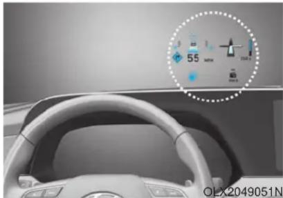
natural_image
Interior view of a car dashboard with steering wheel and digital display (no readable text or symbols)The Head-Up Display is an optional feature that allows the driver to view information projected onto a transparent screen while still keeping your eyes safely on the road ahead while driving.
Precautions while using the head up display
It may sometimes be difficult to read information on the head up display in the following situations.
- The driver is improperly positioned in the driver's seat.
- The driver wears polarizing-filter sunglasses.
- An object is located above the head up display cover.
- The vehicle is driven on a wet road.
- Any improper lighting accessory is installed inside the vehicle, or there is incoming light from outside of the vehicle.
- The driver wears glasses.
- The driver wears contact lenses.
When it is difficult to read the head up display information, adjust the head up display angle or the head up display brightness level in the User Settings mode. For more details, refer to "LCD Display" in this chapter.
WARNING
- Do not tint the front windshield glass or add other types of metallic coating. Otherwise, the head up display image may be invisible.
- Do not place any accessories on the crash pad or attach any objects on the windshield glass.
- The Blind-spot Collision Warning (BCW) system warnings on the head up display are supplemental. Do not solely depend on them to change lanes. Always take a look around before changing lanes.
NOTICE
When replacing the front windshield glass of the vehicle equipped with the head up display, replace it with a windshield glass designed for the head up display operation. Otherwise, duplicated images may be displayed on the windshield glass.
Head-up display ON/OFF
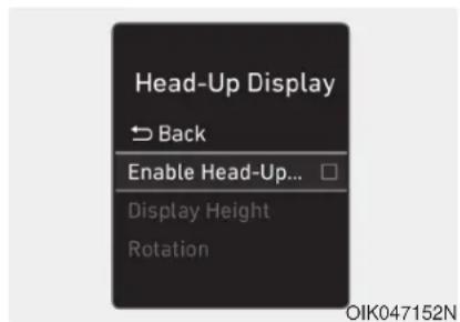
To activate the head up display, select 'Head-UP Display' on the User Settings mode on the instrument cluster LCD display.
If you do not select 'Head-Up Display', the head up display will be deactivated.
Head-up display information
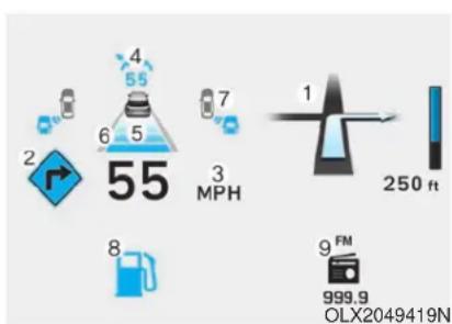
- Turn By Turn (TBT) navigation information (if equipped)
- Speed limit signs (if equipped)
- Speedometer
- Cruise setting speed (if equipped)
- Smart Cruise Control (SCC) information (if equipped)
- Lane Keeping Assist (LKA) system information (if equipped)
- Blind-spot Collision Warning (BCW) system information (if equipped)
- Warning lights (Low fuel, etc.)
- Audio/Video information
i Information
If you select the Turn By Turn (TBT) navigation information as HUD contents, the Turn By Turn (TBT) navigation information will not be displayed in the instrument cluster LCD display.
Head-up display setting
On the LCD display, you can change the head up display settings as follows.
- Enable Head-up display
- Display Height
- Rotation
- Brightness
- Content Selection
- Speed Size
- Speed Color
For more details, refer to "LCD Display" in this chapter.
LIGHTING
Exterior Lights
Lighting control
To operate the lights, turn the knob at the end of the control lever to one of the following positions:
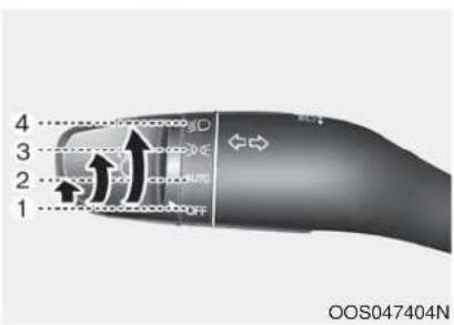
- OFF position
- AUTO headlamp position
- Parking lamp position
- Headlamp position
Daytime running light (DRL)
The Daytime Running Lights (DRL) can make it easier for others to see the front of your vehicle during the day, especially after dawn and before sunset.
The DRL system will turn the dedicated lamp OFF when :
• The headlamps are ON.
• The parking lamps are ON.
• The vehicle is turned off.
• The parking brake is engaged.
• The headlamps are ON.
• The parking lamps are ON.
• The vehicle is turned off.
• The parking brake is engaged.
The DRL system will turn the dedicated lamp OFF when :
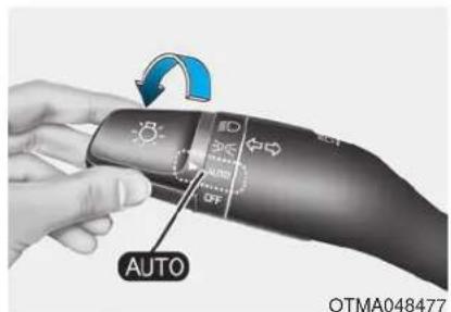
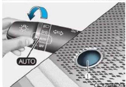
AUTO headlamp position
The parking lamp and headlamp will be turned ON or OFF automatically depending on the amount of daylight as measured by the ambient light sensor (1) on the center dash.
Even with the AUTO headlamp feature in operation, it is recommended to manually turn ON the headlamps when driving at night or in a fog, driving in the rain, or when you enter dark areas, such as tunnels and parking facilities.
NOTICE
- Do not cover or spill anything on the sensor (1) located in front of the instrument panel.
- Do not clean the sensor using a window cleaner, the cleanser may leave a light film which could interfere with sensor operation.
- If your vehicle has window tint or other types of metallic coating on the front windshield, the AUTO headlamp system may not work properly.
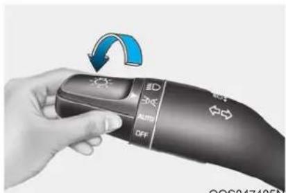
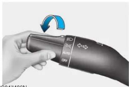
OOS047405N OOS047406N
Parking lamp position (200
The parking lamp, license plate lamp and instrument panel lamp are turned ON.
Headlamp position (3)
The headlamp, parking lamp, license plate lamp and instrument panel lamp are turned ON.
i Information
The ignition switch must be in the ON position to turn on the headlamp.
High beam operation
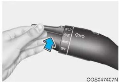
To turn on the high beam headlamp, push the lever away from you. The lever will return to its original position. The high beam indicator will light when the headlamp high beams are switched on.
To turn off the high beam headlamp, pull the lever towards you. The low beams will turn on.
WARNING
Do not use high beam when there are other vehicles approaching you. Using high beam could obstruct the other driver's vision.
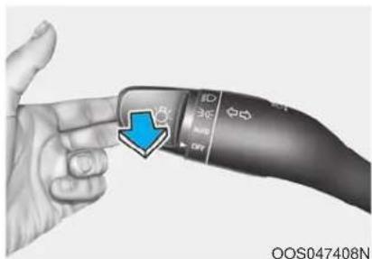
To flash the high beam headlamp, pull the lever towards you, then release the lever. The high beams will remain ON as long as you hold the lever towards you.
High Beam Assist (HBA) (if equipped)
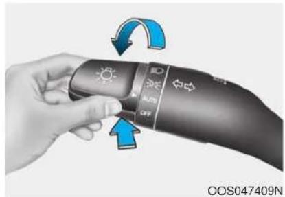
The High Beam Assist (HBA) is a system that automatically adjusts the headlamp range (switches between high beam and low beam) according to the brightness of other vehicles and road conditions.
Operating condition
- Place the headlamp switch in the AUTO position.
- Turn on the high beam by pushing the lever away from you. The High Beam Assist (HBA) (ID indicator will illuminate.
-
The High Beam Assist (HBA) will turn on when vehicle speed is above 25 mph (40 km/h).
-
If the headlamp switch is pushed away when the High Beam Assist (HBA) is operating, the High Beam Assist (HBA) will turn off and the high beam will be on continuously.
- If the headlamp switch is pulled towards you when the high beam is off, the high beam will turn on without the High Beam Assist (HBA) canceled. When you let go of the light switch, the lever will move to the middle and the high beam will turn off.
- If the headlamp switch is pulled towards you when the high beam is on by the High Beam Assist (HBA), the low beam will be on and the High Beam Assist (HBA) will turn off.
- If the headlamp switch is placed to the headlamp ON position, the High Beam Assist (HBA) will turn off and the low beam will be on continuously.
When the High Beam Assist (HBA) is operating, the high beam switches to low beam if any of the following conditions occur :
- When the headlamp of an on-coming vehicle is detected.
- When the tail lamp of a vehicle in front is detected.
- When the headlamp or tail lamp of a motorcycle or a bicycle is detected.
- When the surrounding ambient light is bright enough that high beams are not required.
- When streetlights or other lights are detected.
- When the headlamp switch is not in the AUTO position.
- When the High Beam Assist (HBA) is off.
- When vehicle speed is below 15 mph (24 km/h).
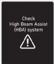
OIK047132N
Warning light and message
When the High Beam Assist (HBA) is not working properly, the Check High Beam Assist warning message will come on for a few second. After the message disappears, the master warning light (⚠️ will illuminate.
Take your vehicle to an authorized HYUNDAI dealer and have the system checked.
WARNING
The system may not operate normally if any of the following conditions should occur:
1) When the illumination from an on-coming vehicle or a vehicle in front is dim. Such examples may include:
- When the headlamps of an on-coming vehicle or the tail lamps of a vehicle in front is covered with dust, snow, or water.
- When the headlamps on an on-coming vehicle are OFF, but the fog lamps are ON.
2) When the High Beam Assist camera is adversely affected by an external condition. Such examples may include:
- When the vehicle's head-lamps have been damaged or not repaired properly.
- When the vehicle headlamps are not aimed properly.
- When the vehicle is driven on a narrow curved road or rough road.
- When the vehicle is driven on an uphill road or downhill road.
- When only part of the vehicle in front is visible on a crossroad or curved road.
- When there is a traffic light, reflecting sign, flashing sign or mirror.
- When the road conditions are bad such as being wet or covered with snow.
- When a vehicle suddenly appears from a curve.
- When the vehicle is tilted from a flat tire or being towed.
- When the Lane Keeping Assist (LKA) system warning light illuminates.
-
When the light from the oncoming or front vehicle is not detected because of exhaust fume, smoke, fog, snow, etc.
-
When the front window is covered with foreign matters such as ice, dust, fog, or is damaged.
3) When the forward visibility is poor. Such examples may include: - When the headlamps of an oncoming vehicle or a vehicle in front is not detected due to poor outside visibility (smog, smoke, dust, fog, heavy rain, snow, etc.).
- When the windshield visibility is poor.
WARNING
- Do not attempt to disassemble the front view camera without the assistance of an authorized HYUNDAI dealer technician. If camera is removed for any reason, the system may need to be re-calibrated. Have the system inspected by an authorized HYUNDAI dealer.
- If the windshield of your vehicle is replaced, most likely the front view camera will need to be re-calibrated. If this occurs, have your vehicle inspected and have the system re-calibrated by an authorized HYUNDAI dealer.
-
Be careful that water doesn't get into the High Beam Assist (HBA) unit and do not remove or damage related parts of the High Beam Assist (HBA) system.
-
Do not place objects on the crash pad that reflect light such as mirrors, white paper, etc. The system may malfunction if sunlight is reflected.
- At times, the High Beam Assist (HBA) may not work properly. The system is for your convenience only. It is the responsibility of the driver for safe driving practices and always check the road conditions for your safety.
- When the system does not operate normally, change the headlamp position manually between the high beam and low beam.
Turn signals and lane change signals
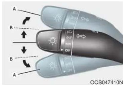
To signal a turn, push down on the lever for a left turn or up for a right turn in position (A).
If an indicator stays on and does not flash or if it flashes abnormally, one of the turn signal bulbs may be burned out and will require replacement.
One-touch turn signal function
To activate the One Touch Turn Signal function, push the turn signal lever up or down to position (B) and then release it.
The lane change signals will blink 3, 5 or 7 times.
You can activate or deactivate the One Touch Turn Signal function or choose the number of blinks (3, 5, or 7) from the User Settings mode in the LCD display.
For more details, refer to the "LCD Display" section in this chapter.
Battery saver function
The purpose of this feature is to help prevent the battery from being discharged. The system automatically turns off the parking lamp when the driver turns the vehicle off and opens the driver-side door.
With this feature, the parking lamps will turn off automatically if the driver parks on the side of road at night.
If necessary, to keep the lamps on when the vehicle is turned off, perform the following:
1) Open the driver-side door.
2) Turn the parking lamps OFF and ON again using the headlamp switch on the steering column.
Headlamp delay function
If the key is removed from the ignition switch or placed in the ACC position or the LOCK/OFF position with the headlamps ON, the headlamps (and/or parking lamps) remain on for about 5 minutes. However, if the driver's door is opened and closed, the headlights are turned off after 15 seconds. Also, with the engine off if the driver's door is opened and closed, the headlamps (and/or parking lamps) are turned off after 15 seconds.
The headlamps (and/or parking lamps) can be turned off by pressing the lock button on the remote key or smart key twice or turning the headlamp switch to the OFF or AUTO position.
You can activate or deactivate the Headlamp Delay function from the User Settings mode in the LCD display.
For more details, refer to the "LCD Display" section in this chapter.
NOTICE
If the driver exits the vehicle through another door besides the driver door, the battery saver function does not operate and the headlamp delay function does not turn OFF automatically.
This may cause the battery to discharge. To avoid battery discharge, turn OFF the headlamps manually from the headlamp switch before exiting the vehicle.
Interior Lights
WARNING
Do not use the interior lights when driving in the dark. The interior lights may obscure your view and cause an accident.
NOTICE
Do not use the interior lights for extended periods when the vehicle is turned off or the battery will discharge.
Interior lamp AUTO cut
The interior lamps will automatically go off approximately 20 minutes after the engine is turned off and the doors are closed. If a door is opened, the lamp will go off 40 minutes after the engine is turned off. If the doors are locked by the remote key or smart key and the vehicle enters the armed stage of the theft alarm system, the lamps will go off five seconds later.
Front lamps
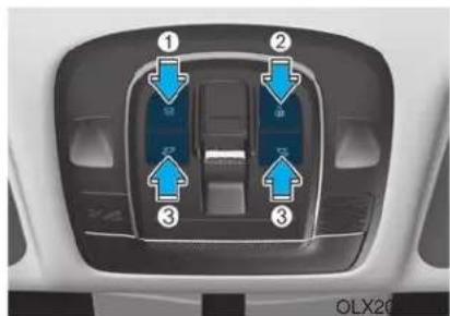
Front Room Lamp (1) ()
Press the button to turn the front and rear room lamps on or off.
Front Door Lamp (2)

The front or rear room lamps come on when the front or rear doors are opened if the engine is running or not. When doors are unlocked by the remote key or smart key, the front and rear lamps come on for approximately 30 seconds as long as any door is not opened. The front and rear room lamps go out gradually after approximately 30 seconds when the door is closed. However, if the ignition switch is in the ON position or all doors are locked, the front and rear lamps will turn off. If a door is opened with the ignition switch in the ACC position or the OFF position, the front and rear lamps stay on for about 20 minutes.
Front Map Lamp (3) :
Press either or switches ( ) to turn the map lamp on or off. This light produces a spot beam for convenient use as a map lamp at night or as a personal lamp for the driver and the front passenger.
Rear lamp
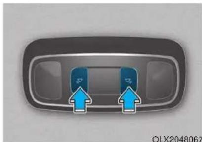
natural_image
Top-down view of a car dashboard with two blue directional arrows pointing up (no text or symbols)Rear Room Lamp ( )
Press either buttons to turn the room lamp on or off.
Luggage compartment lamp
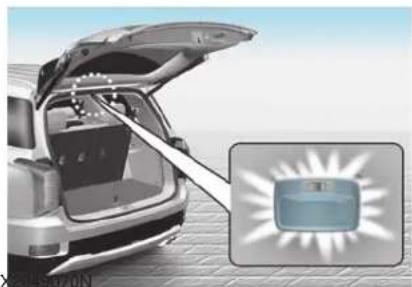
natural_image
Illustration of a car trunk with open lid and zoomed-in inset showing a blue box (no text or symbols)• ON ()
The luggage compartment lamp stays on at all times.
- DOOR ( )
The luggage compartment lamp comes on when the liftgate is opened.
• OFF ()
The luggage compartment lamp is off.
Vanity mirror lamp (if equipped)
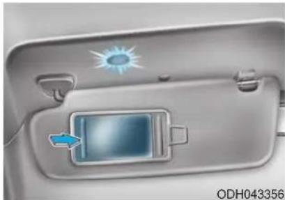
natural_image
Interior view of a car's front panel showing a sun icon and a blue screen with an arrow (no text or symbols)Opening the lid of the vanity mirror will automatically turn on the mirror light.
NOTICE
To prevent unnecessary charging system drain, close the vanity mirror cover after using the mirror.
Glove box lamp (if equipped)
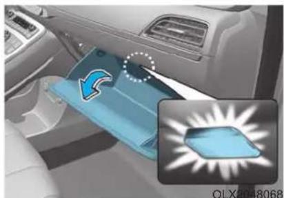
natural_image
Interior view of a car showing a blue car interior with a highlighted airflow path and an inset image of a device (no text or symbols visible)The glove box lamp comes on when the glove box is opened. If the glove box is not closed, the lamp will turn off after 20 minutes.
NOTICE
To prevent unnecessary charging system drain, close the glove box securely after using the glove box.
Puddle lamp (if equipped)
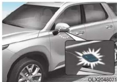
natural_image
Side view of a silver SUV with a partially visible flag featuring a white sunburst design (no text or symbols on the vehicle itself)Welcome light
When all doors (and liftgate) are closed and locked, the puddle lamp will come on for 15 seconds if the door is unlocked by the remote key or smart key or outside door handle button.
For more details, refer to "Welcome System" in this chapter.
Escort light
When the vehicle is turned OFF and the driver's door is opened, the puddle lamp will come on for 30 seconds. If the driver's door is closed within the 30 seconds, the puddle lamp will turn off after 15 seconds. If the driver's door is closed and locked, the puddle lamp will turn off immediately.
The Puddle Lamp Escort Light will turn on only the first time the driver's door is opened after the engine is turned off.
Welcome System (if equipped)
Welcome light
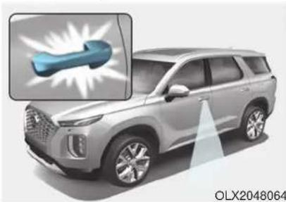
natural_image
Exterior view of a modern SUV with a highlighted blue tool icon (no text or symbols on the vehicle itself)Puddle lamp (if equipped) and door handle lamp (if equipped)
When all the doors (and liftgate) are closed and locked, the puddle lamp and door handle lamp will come on for about 15 seconds if any of the below is performed.
- When the door unlock button is pressed on the remote key or smart key.
- When the button of the outside door handle is pressed with the smart key in possession.
- If 'Convenience → Welcome Light → On driver approach' is selected in the User Settings mode in the cluster LCD display, the lamps will turn on when the vehicle is approached with the smart key in possession.
Headlamp and parking lamp
When the headlamp (lamp switch in the headlamp or AUTO position) is on and all doors (and liftgate) are locked and closed, the parking lamp and headlamp will come on for 15 seconds when the door unlock button is pressed on the remote key or smart key.
At this time, if you press the door lock or unlock button, the parking lamp and headlamp will turn off immediately.
Interior lamp
When the interior lamp switch is in the DOOR position and all doors (and liftgate) are closed and locked, the room lamp will come on for 30 seconds if any of the below is performed.
- When the door unlock button is pressed on the remote key or smart key.
- When the button of the outside door handle is pressed with the smart key in possession.
At this time, if you press the door lock or unlock button on the smart key the room lamp will turn off immediately.
WIPERS AND WASHERS
■Front windshield wiper/washer
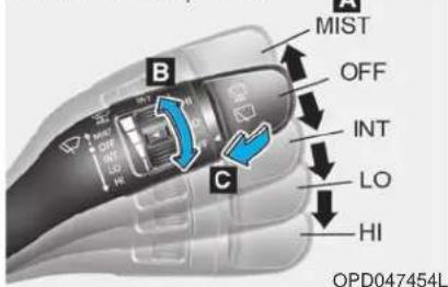
■Rear window wiper/washer
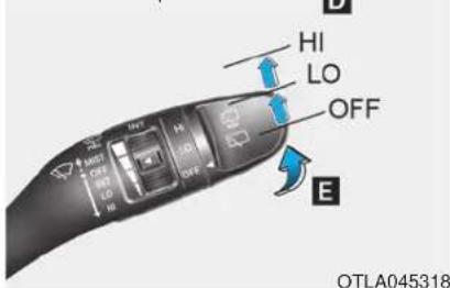
A : Wiper speed control
· MIST – Single wipe
· OFF - Off
- INT – Intermittent wipe
AUTO* – Auto control wipe
- LO - Low wiper speed
- HI – High wiper speed
B : Intermittent control wipe time adjustment
C : Wash with brief wipes (pull lever towards you)
D : Rear wiper/washer control
· HI – High wiper speed
- LO - Low wiper speed
· OFF - Off
E : Wash with brief wipes (rear) (push lever away from you)
*: if equipped
Front Windshield Wipers
Operates as follows when the ignition switch is in the ON position.
MIST: For a single wiping cycle, push the lever upward and release. The wipers will operate continuously if the lever is held in this position.
OFF : Wiper is not in operation.
INT : Wiper operates intermittently at the same wiping intervals. To vary the speed setting, move the speed control lever. The top most setting will run the wipers most frequently (for more rain). The bottom setting will run the wipers the least frequently (for less rain).
AUTO : The rain sensor located on the upper end of the windshield glass senses the amount of rainfall and controls the wiping cycle for the proper interval. The more it rains, the faster the wiper operates. When the rain stops, the wiper stops. To vary the speed setting, turn the speed control knob (B).
LO : The wiper runs at a lower speed. HI : The wiper runs at a higher speed.
i Information
If there is heavy accumulation of snow or ice on the windshield, defrost the windshield for about 10 minutes, or until the snow and/or ice is removed before using the windshield wipers to ensure proper operation.
If you do not remove the snow and/or ice before using the wiper and washer, it may damage the wiper and washer system.
AUTO (Automatic) control (if equipped)
The rain sensor located on the upper end of the windshield glass senses the amount of rainfall and controls the wiping cycle for the proper interval.
The wiper operation time will be automatically controlled depends on rainfall.
When the rain stops, the wiper stops. To vary the sensitivity setting, turn the sensitivity control knob (1).
If the wiper switch is set in AUTO mode when the ignition switch is in the ON position, the wiper will operate once to perform a self-check of the system. Set the wiper to OFF position when the wiper is not in use.
WARNING
To avoid personal injury from the windshield wipers, when the engine is running and the windshield wiper switch is placed in the AUTO mode:
- Do not touch the upper end of the windshield glass facing the rain sensor.
- Do not wipe the upper end of the windshield glass with a damp or wet cloth.
- Do not put pressure on the windshield glass.
NOTICE
- When washing the vehicle, set the wiper switch in the OFF position to stop the auto wiper operation. The wiper may operate and be damaged if the switch is set in the AUTO mode while washing the vehicle.
- Do not remove the sensor cover located on the upper end of the passenger side windshield glass. Damage to system parts could occur and may not be covered by your vehicle warranty.
- Because of using a photo sensor, temporary malfunction could occur according to sudden ambient light change made by stone and dust while driving.
Front Windshield Washers
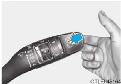
In the OFF position, pull the lever gently toward you to spray washer fluid on the windshield and to run the wipers 1-3 cycles. The spray and wiper operation will continue until you release the lever. If the washer does not work, you may need to add washer fluid to the washer fluid reservoir.

WARNING
When the outside temperature is below freezing, ALWAYS warm the windshield using the defroster to help prevent the washer fluid from freezing on the windshield and obscuring your vision which could result in an accident and serious injury or death.
NOTICE
• To prevent possible damage to the washer pump, do not operate the washer when the fluid reservoir is empty.
• To prevent possible damage to the wipers or windshield, do not operate the wipers when the windshield is dry.
• To prevent damage to the wiper arms and other components, do not attempt to move the wipers manually.
• To prevent possible damage to the wipers and washer system, use anti-freezing washer fluids in the winter season or cold weather.
Rear Window Wiper and Washer
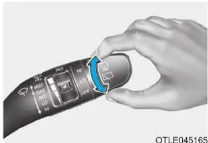
The rear window wiper and washer switch is located at the end of the wiper and washer switch lever. Turn the switch to the desired position to operate the rear wiper and washer.
HI – High wiper speed LO – Low wiper speed OFF – Off
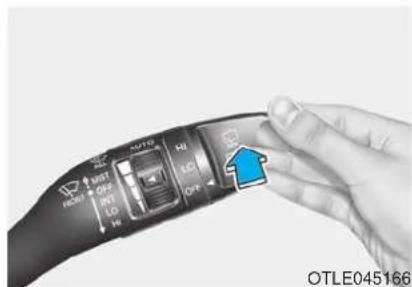
Push the lever away from you to spray rear washer fluid and to run the rear wipers 1\~3 cycles. The spray and wiper operation will continue until you release the lever.
Auto rear wiper
The rear wiper will operate while the vehicle is in reverse with the front wiper ON by selecting the function on the LCD display.
Go to 'User Settings → Convenience → Auto Rear Wiper (in R)'.
Rear View Monitor (if equipped)
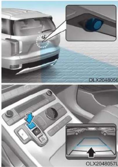
The Rear View Monitor will activate when the engine is running and the shift button is in the R (Reverse) position.
This is a supplemental system that helps provide a view of the area behind the vehicle through the infotainment system screen while the vehicle is in the R (Reverse) position.
WARNING
The Rear View Monitor is not a safety device. It only serves to assist the driver in identifying objects directly behind the middle of the vehicle. The camera does NOT cover the complete area behind the vehicle.
WARNING
- Never rely solely on the Rear view monitor when backing-up.
• ALWAYS look around your vehicle to make sure there are no objects or obstacles before moving the vehicle in any direction to prevent a collision.
• Always pay close attention when the vehicle is driven close to objects, particularly pedestrians, and especially children.
NOTICE
Always keep the camera lens clean. The camera may not work normally if the lens is covered with dirt, water or snow.
Surround View Monitoring (if equipped)
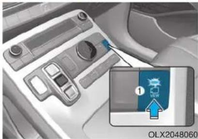
natural_image
Interior view of a car dashboard with a highlighted touchscreen device (no readable text or symbols)The Surround View Monitoring system can assist in parking by allowing the driver to see around the vehicle. Push the button (1, indicator ON) to operate the system. To cancel the system, push the button again (1, indicator OFF).
The system is activated when:
• The engine is ON
- The shift button is in D (Drive), N (Neutral) or R (Reverse)
- Vehicle speed is under 10 mph (15 km/h)
The system is deactivated when:
- You press the button (1) again
• Vehicle speed is over 10 mph (15 km/h)
i Information
- When vehicle speed is over 10 mph (15 km/h), the system will turn off. The system will not automatically turn on again, even though vehicle speed gets below 10 mph (15 km/h). Push the button (1, indicator ON) again, to turn on the system.
- When the vehicle is backing up, the system will turn ON regardless of vehicle speed or button status. However, if vehicle speed is over 10 mph (15 km/h) when driving forward, the SVM system will turn off.
• A warning appears on the system when: - The liftgate is opened
- The driver's door is opened
- The passenger's door is opened
- The outer side view mirror is folded
- If the system is not operating normally, the system should be checked by an authorized HYUNDAI dealer.
For more details, refer to the separately supplied manual with your vehicle.

CAUTION
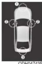
(1) Front camera
(2) Left/Right camera
(3) Rear camera
Surround View Monitor system only serves to assist the driver in parking. ALWAYS look around your vehicle to make sure there are no objects or obstacles before moving the vehicle.
NOTICE
Always keep the camera lens clean. The camera may not work normally if the lens is covered with foreign material.
Blind-spot View Monitor system (if equipped)
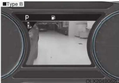
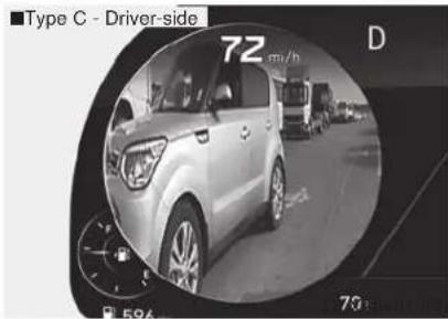
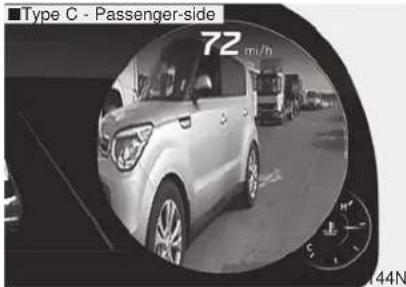
BVM (Blind-spot View Monitor) system displays the driver-side or passenger-side rear areas in the cluster when the system is activated.
To turn on BVM system: Under condition BVM system is enabled in the settings
- The ignition switch is turned to the ON position.
- The turn signal is activated
To turn off BVM system
- The ignition switch is turned to the OFF position.
- The turn signal is deactivated
- Other warning screen pops up and takes priority over the BVM system.
System setting
With the engine ON, the Blind-spot View Monitor system turns on and gets ready to be activated when the 'User Settings → Driver Assistance → Blind-spot safety → Blind-spot view' is selected on the cluster. The system stops operation when the setting is deactivated.
CAUTION
- Like all assistance systems, BVM system has limitations. Over-reliance on the system may result in a collision.
• Always look around your vehicle to make sure there are no objects or obstacles before moving the vehicle in any direction to prevent a collision. - Objects are closer than they appear. Failure to visually confirm that is safe to change the lane before doing so may result in crash and serious injury or death.
• Always keep the camera lens clean. The camera may not work normally if the lens is covered with foreign material.
Parking Distance Warning (Reverse) System (if equipped)
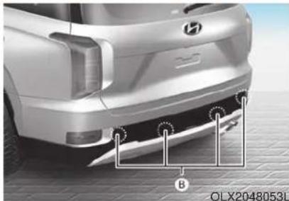
natural_image
Front view of a silver car's rear bumper with a visible logo and mounting bracket (no text or symbols on the car itself)The optional Parking Distance Warning (Reverse) system assists the driver during reverse movement of the vehicle by chiming if any object is sensed within approximately 50 in (120 cm) behind the vehicle.
This system is a supplemental system that senses objects within the range and location of the sensors, it cannot detect objects in other areas where sensors are not installed.
WARNING
- ALWAYS look around your vehicle to make sure there are not any objects or obstacles before moving the vehicle in any direction to prevent a collision.
• Always pay close attention when the vehicle is driven close to objects, particularly pedestrians, and especially children. - Be aware that some objects may not be visible on the screen or be detected by the sensors, due to the objects distance, size or material, all of which can limit the effectiveness of the sensor.
Operation of the Parking Distance Warning (Reverse) system
Operating condition
- This system will activate when backing up with the ignition switch in the ON position. However, if the vehicle speed exceeds 3 mph (5 km/h), the system may not detect objects.
- If the vehicle speed exceeds 6 mph (10 km/h), the system will not warn you even though objects are detected.
- When more than two objects are sensed at the same time, the closest one will be recognized first.
Types of warning sound and indicator
Types of warning sound Indicator
When an object is 24 to 47 in (60 to 120 cm) from the rear bumper, the warning sound beeps intermittently.
When an object is 12 to 24 in (30 to 60 cm) from the rear bumper, the warning sound beeps more frequently.
When an object is within 12 in (30 cm) from the rear bumper, the warning sound beeps continuously.
NOTICE
• The indicator may differ from the illustration as objects or sensors status. If the indicator blinks, have your vehicle checked by an authorized HYUNDAI dealer.
- If the audible warning does not sound or if the buzzer sounds intermittently when shifting into R (Reverse) position, this may indicate a malfunction with the Parking Distance Warning (Reverse) system. If this occurs, have your vehicle checked by an authorized HYUNDAI dealer as soon as possible.
To Turn OFF the Parking Distance Warning (Reverse) system
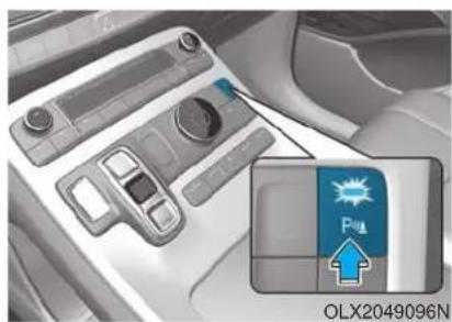
natural_image
Interior view of a car dashboard with control panel and indicator lights (no readable text or symbols)Push the button to turn OFF the Parking Distance Warning (Reverse) system. The indicator light on the button will turn on.
Conditions Where the Parking Distance Warning (Reverse) system May Not Operate
The Parking Distance Warning (Reverse) system may not operate normally when any of the following occur:
- The sensor is covered with dirt or debris such as snow or ice, or the sensor cover is blocked.
The Parking Distance Warning (Reverse) system may experience a malfunction when the following occurs:
- Driving on uneven road surfaces such as unpaved roads, gravel, bumps, or gradient.
- Objects generating excessive noise such as vehicle horns, loud motorcycle engines, or truck air brakes can interfere with the sensor.
- Heavy rain or water spray is present.
-
Wireless transmitters or mobile phones are present near the sensor.
-
The sensor is covered with snow.
- Any non-factory equipment or accessories have been installed, or if the vehicle bumper height or sensor installation has been modified.
Detecting range may decrease when:
- Outside air temperature is extremely hot or cold.
- Undetectable objects smaller than 40 inches (1 m) and narrower than 6 inches (14 cm) in diameter.
The following objects may not be recognized by the sensor:
- Sharp or slim objects such as ropes, chains or small poles.
- Objects, which tend to absorb sensor frequency such as clothes, spongy material or snow.
Parking Distance Warning (Reverse) system Precautions
- The Parking Distance Warning (Reverse) system may not operate consistently in some circumstances depending on the speed of the vehicle and the shapes of the objects detected.
- The Parking Distance Warning (Reverse) system may malfunction if the vehicle bumper height or sensor installation has been modified or damaged. Any non-factory installed equipment or accessories may also interfere with the sensor performance.
- The sensor may not recognize objects less than 12 in. (30 cm) from the sensor, or it may sense an incorrect distance. Use caution.
-
When the sensor is blocked with snow, dirt, debris, or ice, the rear parking assist system may be inoperative until the snow or ice melts, or the debris is removed. Use a soft cloth to wipe debris away from the sensor.
-
Do not push, scratch or strike the sensor with any hard objects that could damage the surface of the sensor. Sensor damage could occur.
- Do not spray the sensors or its surrounding area directly with a high pressure washer. Doing so may cause the sensors to fail to operate normally.
WARNING
Extreme caution should always be taken to avoid accidents or vehicle injuries. Do not solely rely on the Parking Distance Warning (Reverse) system. Always drive safely and cautiously, especially when backing up in reverse.
Parking Distance Warning (Reverse/Forward) System (if equipped)
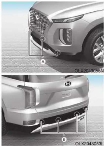
A: Front Sensor, B: Rear Sensor
The Parking Distance Warning (Reverse/Forward) system assists the driver during movement of the vehicle by chiming if any object is sensed within the distance of 39 inches (100 cm) in front and 47 inches (120 cm) behind the vehicle.
This system is a supplemental system that senses objects within the range and location of the sensors, it cannot detect objects in other areas where sensors are not installed.
WARNING
• ALWAYS look around your vehicle to make sure there are no objects or obstacles before moving the vehicle in any direction to prevent a collision.
• Always pay close attention when the vehicle is driven close to objects, particularly pedestrians, and especially children.
- Be aware that some objects may not be visible on the screen or be detected by the sensors, due to the objects distance, size or material, all of which can limit the effectiveness of the sensor.
Operation of the Parking Distance Warning (Reverse/Forward) System
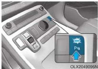
natural_image
Interior view of a car dashboard with control panel and indicator light (no readable text or symbols)Operating condition
- This system will activate when the Parking Distance Warning system button is pressed with the engine running.
- Sensing distance when backing up is approximately 47 in (120 cm) when you are driving less than 6 mph (10 km/h).
-
Sensing distance when moving forward is approximately 39 in (100 cm) when you are driving less than 6 mph (10 km/h).
-
When more than two objects are sensed at the same time, the closest one will be recognized first.
- If you push R (Reverse) position button on shift button with the engine running and the Parking Distance Warning system off, the system will operate automatically.
Types of warning sound and indicator
| Distance from object Inches (cm) | Warning indicator | Warning sound | |||||
| When driving forward | When driving rearward | ||||||
| 24 ~ 39(61 ~ 100) | Front |  | Buzzer beeps intermittently | ||||
| 24 ~ 47(61 ~ 120) | Rear |  | Buzzer beeps intermittently | ||||
| 12 ~ 24(31 ~ 60) | Front |  |  | Buzzer beeps frequently | |||
| Rear | Buzzer beeps frequently | ||||||
| 12(30) | Front |  |  | Buzzer sounds continuously | |||
| Rear | Buzzer sounds continuously | ||||||
i Information
- The indicator may differ from the illustration depending on objects or sensors status. If the indicator blinks, have your vehicle checked by an authorized HYUNDAI dealer.
- If the audible warning does not sound or if the buzzer sounds intermittently when shifting into R (Reverse) position, this may indicate a malfunction with the Parking Distance Warning (Reverse/Forward) system. If this occurs, have your vehicle checked by an authorized HYUNDAI dealer as soon as possible.
Non-operational conditions of Parking Distance Warning (Reverse/Forward) system
The Parking Distance Warning (Reverse/Forward) system may not operate normally when any of the following occur:
- Moisture is frozen to the sensor.
- Sensor is covered with foreign matter, such as snow or water, or the sensor cover is blocked.
The Parking Distance Warning (Reverse/Forward) system may experience a malfunction when the following occurs:
- Driving on uneven road surfaces such as unpaved roads, gravel, bumps, or gradient.
- Objects generating excessive noise such as vehicle horns, loud motorcycle engines, or truck air brakes can interfere with the sensor.
- Heavy rain or water spray is present.
- Wireless transmitters or mobile phones are present near the sensor.
• The sensor is covered with snow.
- Any non-factory equipment or accessories have been installed, or if the vehicle bumper height or sensor installation has been modified.
Detecting range may decrease when:
- Outside air temperature is extremely hot or cold.
- Undetectable objects smaller than 40 inches (1 m) and narrower than 6 inches (14 cm) in diameter.
The following objects may not be recognized by the sensor:
- Sharp or slim objects such as ropes, chains or small poles.
- Objects, which tend to absorb sensor frequency such as clothes, spongy material or snow.
Parking Distance Warning (Reverse/Forward) system precautions
- The Parking Distance Warning (Reverse/Forward) system may not operate consistently in some circumstances depending on the speed of the vehicle and the shapes of the objects detected.
- The Parking Distance Warning (Reverse/Forward) system may malfunction if the vehicle bumper height or sensor installation has been modified or damaged. Any non-factory installed equipment or accessories may also interfere with the sensor performance.
- The sensor may not recognize objects less than 15 inches. (40 cm) from the sensor, or it may sense an incorrect distance. Use caution.
- When the sensor is blocked with snow, dirt, debris, or ice, the system may be inoperative until the snow or ice melts, or the debris is removed. Use a soft cloth to wipe debris away from the sensor.
- Do not push, scratch or strike the sensor with any hard objects that could damage the surface of the sensor. Sensor damage could occur.
- Do not spray the sensors or its surrounding area directly with a high pressure washer. Doing so may cause the sensors to fail to operate normally.
WARNING
Your new vehicle warranty does not cover any accidents or damage to the vehicle or injuries to its occupants related to a Parking Distance Warning (Reverse/Forward) system.
Always drive safely and cautiously.
MANUAL CLIMATE CONTROL SYSTEM (IF EQUIPPED)
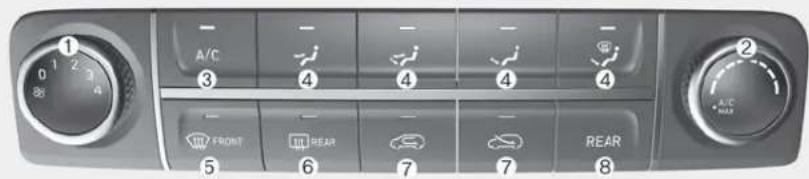
Front
- Fan speed control knob
- Temperature control knob
- Air conditioning button
- Mode selection button
- Front windshield defroster button
- Rear window defroster button
- Air intake control button
- Rear climate control button
OLX2048325L
Heating and Air Conditioning
- Start the engine.
- Set the mode to the desired position.
To improve the effectiveness of heating and cooling, select the mode according to the following: - Heating: √
- Cooling:
- Set the temperature control to the desired position.
- Set the air intake control to Fresh mode or Recirculation mode position.
- Set the fan speed control to the desired speed.
- If air conditioning is desired, turn the air conditioning system on.
Mode selection
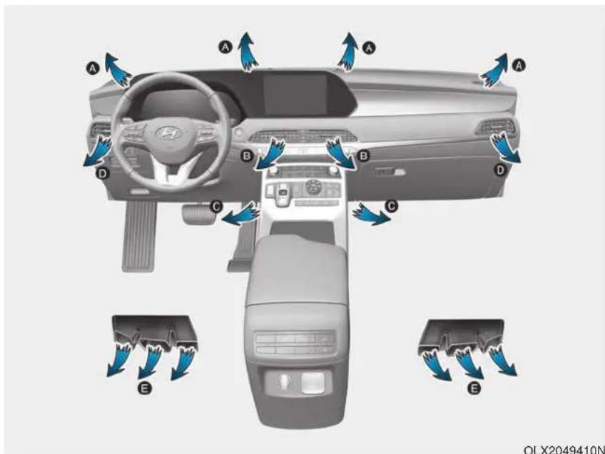
The mode selection button controls the direction of the air flow through the ventilation system. Air can be directed to the floor, dashboard outlets, or windshield. Five symbols are used to represent Face, Bi-Level, Floor, Floor-Defrost and Defrost air position.

Face-Level (B, D)
Air flow is directed toward the upper body and face. Additionally, each outlet can be controlled to direct the air discharged from the outlet.

Bi-Level (B, C, D, E)
Air flow is directed towards the face and the floor.

Floor-Level (A, C, D, E)
Most of the air flow is directed to the floor, with a small amount of the air being directed to the windshield and side window defrosters.

Floor & Defrost (A, C, D, E)
Most of the air flow is directed to the floor and the windshield with a small amount directed to the side window defrosters.
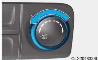
natural_image
Close-up of a car dashboard knob with blue curved arrow indicating clockwise rotation (no text or symbols on the knob itself)MAX A/C-Level (B, D)
The MAX A/C mode is used to cool the inside of the vehicle faster. Air flow is directed toward the upper body and face.
In this mode, the A/C button and the Recirculation mode button will be automatically selected. Turn the fan speed mode to adjust.
After the interior cabin has cooled sufficiently, move the temperature knob away from the MAX A/C setting and adjust the knob to the desired position.
If you wish to continue using A/C ON, make sure the A/C button LED is illuminated.
Instrument panel vents
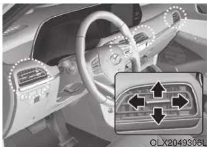
natural_image
Interior view of a car dashboard and steering wheel (no visible text or symbols)The instrument panel vent air flow can be directed up/down or left/right using the vent adjustment lever.
The outlet vents can be opened or closed separately using the vent control lever. If you move the vent control lever to the left end, the outlet vents can be closed.
Temperature control (2)
The temperature will increase by turning the knob to the right.
The temperature will decrease by turning the knob to the left.
Air intake control
The air intake control button is used to select either Fresh mode (outside air) or Recirculation mode (cabin air).
Recirculation mode
When Recirculation mode is selected, air from the passenger compartment will be recirculated through the system and heated or cooled according to the function selected.
Fresh mode
When Fresh mode is selected, air enters the vehicle from outside and is heated or cooled according to the function selected.
i Information
Operating the system primarily in Fresh mode is recommended. Use Recirculation mode temporarily only when needed.
Prolonged operation of the heater in Recirculation mode and without the A/C ON can cause fogging of the windshield.
In addition, prolonged use of the A/C ON in Recirculation mode may result in excessively dry, dehumidified air in the cabin and may promote formation of musty vent odor due to stagnant air.
WARNING
- Continued use of the climate control system operation in Recirculation mode for a prolonged period of time may cause drowsiness to the occupants in the cabin. This may lead to loss of vehicle control which may lead to an accident.
- Continued use of the climate control system operation in Recirculation mode with the A/C OFF may allow humidity to increase inside the cabin. This may cause condensation to accumulate on the windshield and obscure visibility.
- Do not sleep in your vehicle or remain parked in your vehicle with the windows up and either the heater or the air conditioning ON for prolonged periods of time. Doing so may increase the levels of carbon dioxide in the cabin which may lead to serious injury or death.
Fan speed control (1)
Turn the knob to the right to increase the fan speed and airflow. Turn the knob to the left to decrease fan speed and airflow.
Setting the fan speed control knob to the "0" position turns off the fan.
NOTICE
Operating the fan speed when the ignition switch is in the ON position could cause the battery to discharge. Operate the fan speed when the engine is running.
Air conditioning (3)
Push the A/C button to turn the system on (indicator light will illuminate) and off.
Rear climate control button
If you press the rear climate control button, rear passengers can control the rear climate system.
Rear climate control
■2nd row air conditioning control
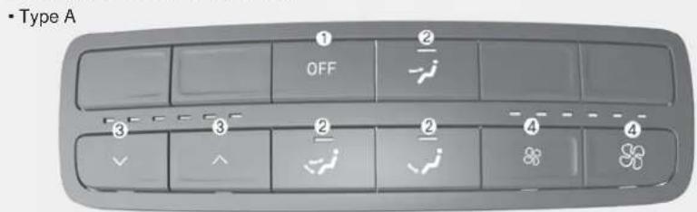
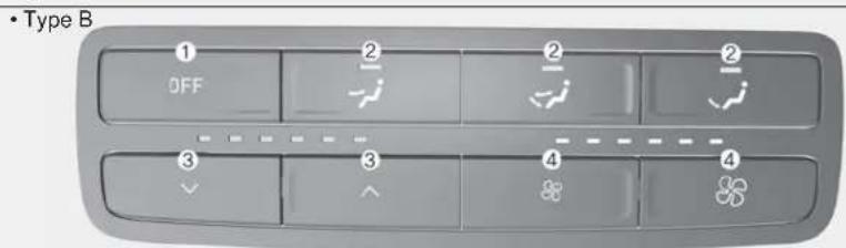
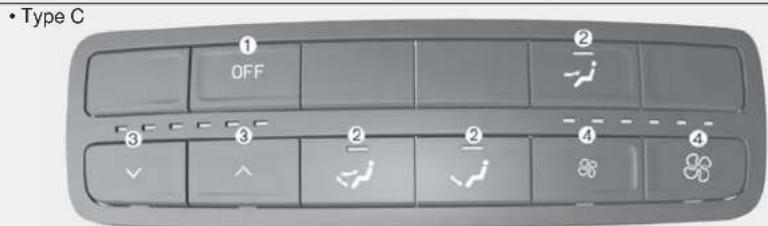
- OFF button
- Mode selection button
- Temperature control button
- Fan speed control button
If you press the rear climate control button of the front climate control system, rear passengers can control the rear climate system by using the rear climate control system.
OLX2048328L/OLX2048329L/OLX2049337N
Fan speed control
- Press the rear climate control button of the front climate control system.
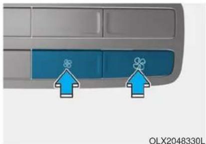
natural_image
Close-up of a car dashboard with blue buttons and directional arrows indicating airflow or ventilation (no text or symbols on the buttons)- The fan speed can be set to the desired speed by pushing the fan speed control button. The higher the fan speed is, the more air is delivered.
Pressing the OFF button turns off the fan.
Temperature control
- Press the rear climate control button of the front climate control system.
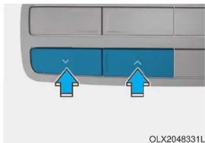
natural_image
Close-up of a car's front panel with blue buttons and directional arrows (no text or symbols)- To turn off the 3rd row air conditioning control system, press the 3rd row air conditioning ON/OFF button once more located on the front climate control panel or set the fan speed to the OFF position with the 3rd row fan speed switch (indicator light on the ON/OFF button is not illuminated).
OFF mode
Push the OFF button to turn the rear climate control system off.
Mode selection
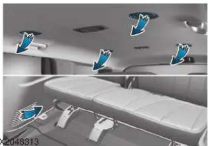
natural_image
Interior view of a modern car with overhead air ducts and seating arrangement (no visible text or symbols)You can select the direction of the air flow through the ventilation system.
You can adjust the front climate control system for heating or cooling to passengers on 2nd row seats. The air flow is directed from the floor.
: Air flow is directed toward the upper body from the rear headliner.
: Air flow is directed toward the upper body and the floor.
: Air flow is directed toward the floor.
Rear vents on the headliner
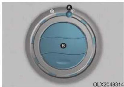
natural_image
Circular industrial control knob with blue liquid and labeled points A and B, no readable text or symbols beyond labelsThe rear passengers can adjust the direction of air flow from the rear vents on the headliner.
If you operate the rear climate control with rear vents closed, a noise may sound. When operating the rear climate control, open two or more rear vents.
| No | Diffusion lever (A) | Direction thumbwheel (B) | Description |
| 1 | Open | Close | The air is delivered widely toward the surroundings of rear passengers.However, the fan speed may be decreased. |
| 2 | Open | Open | The air is delivered widely toward the rear passengers and surrounding of rear passengers. |
| 3 | Close | Open | The air is only delivered toward the rear passengers. |
System Operation
Cooling / Ventilation
- Select the Face Level mode.
- Set the air intake control to fresh mode.
- Set the temperature control to the desired position.
- Set the fan speed control to the desired speed.
Heating
- Select the Floor Level mode.
- Set the air intake control to fresh mode.
- Set the temperature control to the desired position.
- Set the fan speed control to the desired speed.
- If desired, turn the air conditioning ON with the temperature control knob set to heat in order to dehumidify the air before it enters into the cabin.
If the windshield fogs up, select the Floor & Defrost mode or press the Front Defrost mode.
Operation Tips
- To keep dust or unpleasant fumes from entering the vehicle through the ventilation system, temporarily set the air intake control to recirculation mode. Return the control to fresh mode when the unpleasant air outside has diminished. This will help keep the driver alert and comfortable.
- To help prevent the inside of the windshield from fogging, set the air intake control to fresh mode and fan speed to the desired position, turn on the air conditioning system, and adjust the temperature control to the desired temperature.
Air conditioning
Your HYUNDAI vehicle air conditioning system is filled with R-134a refrigerant.
- Start the engine.
- Press the air conditioning button.
- Select the Face Level mode.
- Set the air intake control to Recirculation mode temporarily to allow the cabin to cool quickly. When the desired temperature in the cabin is reached, change the air intake control back to Fresh mode.
- Adjust the fan speed control and temperature control to maintain maximum comfort.
When maximum cooling is desired, set the temperature control to the MAX A/C position, then set the fan speed control to the highest setting.
NOTICE
When using the air conditioning system, monitor the engine temperature gauge closely while driving up hills or in heavy traffic when outside temperatures are high. Air conditioning system operation when climbing a steep grade or in high outside ambient temperatures can cause engine overheating.
Continue to use the fan, but turn the air conditioning system off if the engine temperature gauge indicates engine overheating.
Air conditioning system operation tips
- If the vehicle has been parked in direct sunlight during hot weather, open the windows for a short time to let the hot air inside the vehicle escape.
• After sufficient cooling has been achieved, switch back from recirculation mode to fresh mode.
- To help reduce moisture inside of the windows on rainy or humid days, decrease the humidity inside the vehicle by operating the air conditioning system with the windows and sunroof closed.
- Use the air conditioning system every month only for a few minutes to ensure maximum system performance.
- If you operate air conditioner excessively, the difference between the temperature of the outside air and that of the windshield could cause the outer surface of the windshield to fog up, causing loss of visibility. In this case, set the mode selection knob or button to the position and fan speed control to the lower speed.
System Maintenance
Cabin air filter
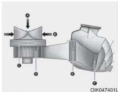
A : Outside air, B : Recirculated air
[C]: Climate control air filter, [D]: Blower
[E] : Evaporator core, [F] : Heater core
The cabin air filter is installed behind the glove box. It filters the dust or other pollutants that enter the vehicle through the heating and air conditioning system.
Have the cabin air filter replaced by an authorized HYUNDAI dealer according to the maintenance schedule. If the vehicle is being driven in severe conditions such as dusty or rough roads and/or if transporting pets or occupants smoke inside the vehicle, then more frequent cabin air filter inspections and changes are required.
If the air flow rate suddenly decreases, the system should be checked at an authorized HYUNDAI dealer.
Checking the amount of air conditioner refrigerant and compressor lubricant
When the amount of refrigerant is low, the performance of the air conditioning is reduced. Overfilling also reduces the performance of the air conditioning system.
Therefore, if abnormal operation is found, have the system inspected by an authorized HYUNDAI dealer.
NOTICE
It is important that the correct type and amount of oil and refrigerant is used. Otherwise, damage to the compressor and abnormal system operation may occur.
WARNING

Because the refrigerant is at very high pressure, the air conditioning system should only be serv-
iced by trained and certified technicians. It is important that the correct type and amount of oil and refrigerant is used, otherwise damage to the vehicle and personal injury may occur.
The air conditioning system should be serviced by an authorized HYUNDAI dealer.
Air Conditioning refrigerant label
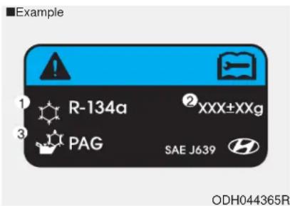
The actual Air Conditioning refrigerant label in the vehicle may differ from the illustration.
Each symbols and specification on air conditioning refrigerant label means as below :
- Classification of refrigerant
- Amount of refrigerant
- Classification of Compressor lubricant
Refer to chapter 8 for more detail location of the air conditioning refrigerant label.
AUTOMATIC CLIMATE CONTROL SYSTEM
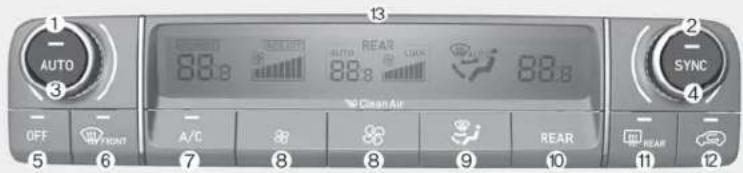
Front
- Driver's temperature control knob
2.Passenger's temperature control knob - AUTO (automatic control) button
- SYNC button
- OFF button
- Front windshield defroster button
- Air conditioning button
- Fan speed control button
- Mode selection button
- Rear climate control button
- Rear window defroster button
12.Air intake control button - Climate control information screen
OLX2048300L
Automatic Temperature Control Mode
The Automatic Climate Control System is controlled by setting the desired temperature.
For your convenience and to improve the efficiency of the climate control, use the AUTO button and set the temperature to 72°F (22°C).
- Press the AUTO button (3).
The modes, fan speeds, air intake and air-conditioning will be controlled automatically by the temperature setting you select.
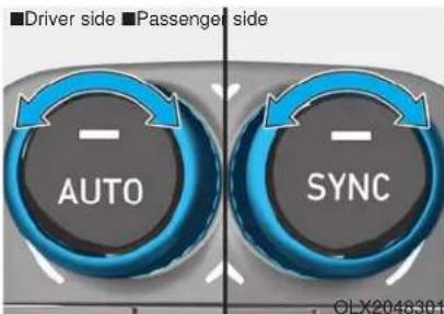
- To select a different set point, turn the temperature control knob to the desired temperature. If the temperature is set to the lowest setting (Lo), the air conditioning system will operate continuously. After the interior has cooled sufficiently, adjust the knob to a higher temperature set point whenever possible.
To turn the automatic operation off, select any button of the following:
- Mode selection button
- Front windshield defroster button (Press the button one more time to deselect the front windshield defroster function. The 'AUTO' sign will illuminate on the information display once again.)
- Fan speed control button
The selected function will be controlled manually while other functions operate automatically.
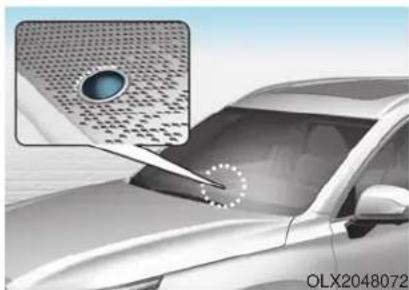
natural_image
Illustration of a car with a magnified inset showing a blue circular object on its surface (no text or symbols)NOTICE
Never place anything near the ambient light/solar sensor to ensure better control of the heating and cooling system.
Manual Temperature Control Mode
The heating and cooling system can be controlled manually by pushing buttons other than the AUTO button. In this case, the system works sequentially according to the order of buttons selected.
When pressing any button except the AUTO button while using automatic operation, the functions not selected will be controlled automatically.
- Start the engine.
-
Set the mode to the desired position.
To improve the effectiveness of heating and cooling, select the mode according to the following: -
Heating: √
-
Cooling:
-
Set the temperature control to the desired position.
- Set the air intake control to Fresh mode.
-
Set the fan speed control to the desired speed.
-
If air conditioning is desired, turn the air conditioning system on.
- Press the AUTO button to convert to full automatic control of the system.
Mode selection (9)
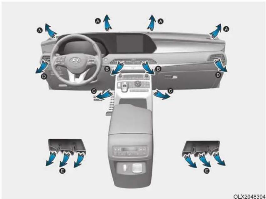
The mode selection button controls the direction of the air flow through the ventilation system.
The air flow outlet direction is cycled as follows:

Air flow is directed toward the upper body and face. Additionally, each outlet can be controlled to direct the air discharged from the outlet.

Air flow is directed towards the face and the floor.

Floor & Defrost (A, C, D, E)
Most of the air flow is directed to the floor and the windshield with a small amount directed to the side window defrosters.

Floor-Level (A, C, D, E)
Most of the air flow is directed to the floor, with a small amount of the air being directed to the windshield and side window defrosters.
Defrost-Level (6) (A, D)
Most of the air flow is directed to the windshield with a small amount of air directed to the side window defrosters.
Instrument panel vents
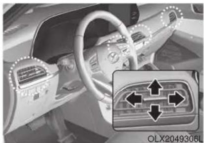
natural_image
Interior view of a car dashboard and steering wheel, showing directional arrows and no visible text or symbols.The instrument panel vent air flow can be directed up/down or left/right using the vent adjustment lever.
The outlet vents can be opened or closed separately using the vent control lever. If you move the vent control lever to the left end, the outlet vents can be closed.
Temperature control
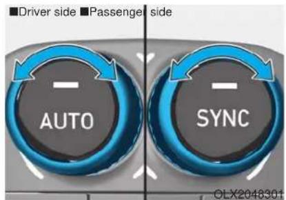
Turn the knob to the right to increase the temperature. Turn the knob to the left to decrease temperature.
The temperature will increase or decrease by 1^ F/0.5°C for each incremental location. When set to the lowest temperature setting, the air conditioning will operate continuously.
Adjusting the driver and passenger side temperature equally
- Press the "SYNC" button to operate the driver and passenger side temperature equally.
The passenger side temperature will be set to the same temperature as the driver side temperature.
- Turn the driver side temperature control knob. The driver and passenger side temperature will be adjusted equally.
Adjusting the driver and passenger side temperature individually
Press the "SYNC" button again to operate the driver and passenger side temperature individually. The button indicator will turn off.
Temperature conversion
If the battery has been discharged or disconnected, the temperature mode display will reset to Fahrenheit.
To change the temperature unit from °F to °C or °C to °F:
- On the instrument cluster, go to User Settings → Other → Temperature Unit.
- Press the AUTO button while pressing the OFF button on the climate control unit for 3 seconds.
The temperature unit on both the cluster LCD display and climate control screen will change.
Air intake control (12)
The air intake control button is used to select either Fresh mode (outside air) or Recirculation mode (cabin air).
Recirculation mode
When Recirculation mode is selected, air from the passenger compartment will be recirculated through the system and heated or cooled according to the function selected.
Fresh mode
When Fresh mode is selected, air enters the vehicle from outside and is heated or cooled according to the function selected.
i Information
Operating the system primarily in Fresh mode is recommended. Use Recirculation mode temporarily only when needed.
Prolonged operation of the heater in Recirculation mode and without the A/C ON can cause fogging of the windshield.
In addition, prolonged use of the A/C ON in Recirculation mode may result in excessively dry, dehumidified air in the cabin and may promote formation of musty vent odor due to stagnant air.
WARNING
- Continued use of the climate control system operation in Recirculation mode for a prolonged period of time may cause drowsiness to the occupants in the cabin. This may lead to loss of vehicle control which may lead to an accident.
- Continued use of the climate control system operation in Recirculation mode with the A/C OFF may allow humidity to increase inside the cabin. This may cause condensation to accumulate on the windshield and obscure visibility.
- Do not sleep in your vehicle or remain parked in your vehicle with the windows up and either the heater or the air conditioning ON for prolonged periods of time. Doing so may increase the levels of carbon dioxide in the cabin which may lead to serious injury or death.
Fan speed control (8)
The fan speed can be set as desired by pushing the fan speed control button.
More air is delivered with higher fan speeds.
Pressing the OFF button turns off the fan.
i Information
For better sound quality, fan speed may automatically slow down for a couple of minutes when you activate voice recognition or hands free.
NOTICE
Operating the fan when the ignition switch is in the ON position could cause the battery to discharge. Operate the fan when the engine is running.
Air conditioning (7)
Push the A/C button to manually turn the system on (indicator light will illuminate) and off.
OFF mode (5)
Push the OFF button to turn the climate control system off. You can still operate the mode and air intake buttons as long as the ignition switch is in the ON position.
Rear climate control button
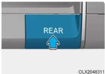
If you press the rear climate control button, rear passengers can control the rear climate system.
Rear climate control
■ 2nd row air conditioning control
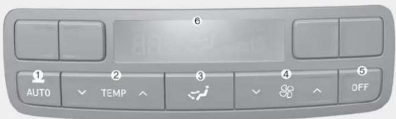
OLX2048318
- AUTO button
- Temperature control button
- Mode selection button
- Fan speed control button
- OFF button
- Climate control information screen
If you press the rear climate control button of the front climate control system, rear passengers can control the rear climate system by using the rear climate control system.
*When you want to use the rear climate control (heating and air conditioning)
- Press the air conditioning button of the front climate control.
- Adjust the rear climate control (temperature, air direction and fan speed).
- Check that "Lock Control" is not selected in the infotainment system. If "Lock Control" is selected, the rear climate control is not adjusted in the rear climate control panel.
Fan speed control
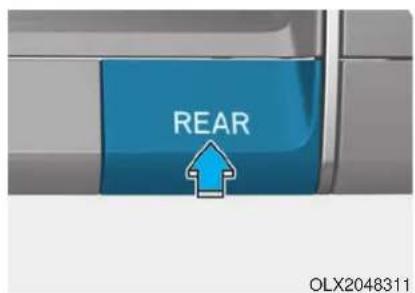
- Press the rear climate control button of the front climate control system.
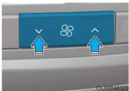
natural_image
Close-up of a blue control panel with two arrows pointing to a flower symbol and an arrow pointing up (no text or labels visible)- The fan speed can be set to the desired speed by pushing the fan speed control button. The higher the fan speed is, the more air is delivered. Pressing the OFF button turns off the fan.
Temperature control
- Press the rear climate control button of the front climate control system.
- The temperature of delivered air can be set to the desired temperature by pushing the temperature control button.
Pressing the OFF button turns off the fan.
AUTO mode
The rear automatic climate control system is controlled by setting the desired temperature.
-
Press the AUTO button. The modes, fan speeds, air intake and air-conditioning will be controlled automatically by the temperature setting you select.
-
Press the temperature control button to the desired temperature.
OFF mode
Push the OFF button (5) to turn the rear climate control system off.
Mode selection
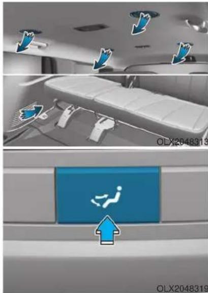
natural_image
Interior view of a medical or rehabilitation facility with overhead airflow arrows and a blue safety sign (no readable text or symbols)You can select the direction of the air flow through the ventilation system.
You can adjust the front climate control system for heating or cooling to passengers on 2nd row seats. The air flow is directed from the floor.

: Air flow is directed toward the upper body from the rear headliner.

: Air flow is directed toward the upper body and the floor.

: Air flow is directed toward the floor.
Rear vents on the headliner
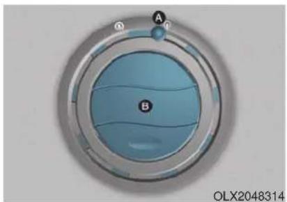
natural_image
Circular device with blue internal components labeled A and B, no visible text or symbols beyond labelsThe rear passengers can adjust the direction of air flow from the rear vents on the headliner.
If you operate the rear climate control with rear vents closed, a noise may sound. When operating the rear climate control, open two or more rear vents.
| No | Diffusion lever (A) | Direction thumbwheel (B) | Description |
| 1 | Open | Close | The air is delivered widely toward the surroundings of rear passengers.However, the fan speed may be decreased. |
| 2 | Open | Open | The air is delivered widely toward the rear passengers and surrounding of rear passengers. |
| 3 | Close | Open | The air is only delivered toward the rear passengers. |
System Operation
Cooling / Ventilation
- Select the Face Level mode.
- Set the air intake control to fresh mode.
- Set the temperature control to the desired position.
- Set the fan speed control to the desired speed.
Heating
- Select the Floor Level mode.
- Set the air intake control to fresh mode.
- Set the temperature control to the desired position.
- Set the fan speed control to the desired speed.
- If desired, turn the air conditioning ON with the temperature control knob set to heat in order to dehumidify the air before it enters into the cabin.
If the windshield fogs up, select the Floor & Defrost mode or press the Front Defrost mode.
Operation Tips
- To keep dust or unpleasant fumes from entering the car through the ventilation system, temporarily set the air intake control to the recirculation mode. Return the control to the to fresh mode when the unpleasant air outside has diminished. This will help keep the driver alert and comfortable.
- To help prevent the inside of the windshield from fogging, set the air intake control to fresh mode and the fan speed to the desired position, turn on the air conditioning system, and adjust the temperature control to the desired temperature.
Air conditioning
Your HYUNDAI vehicle air conditioning system is filled with R-134a refrigerant.
- Start the engine.
- Press the air conditioning button.
- Select the Face Level mode.
- Set the air intake control to Recirculation mode temporarily to allow the cabin to cool quickly. When the desired temperature in the cabin is reached, change the air intake control back to Fresh mode.
- Adjust the fan speed control and temperature control to maintain maximum comfort.
When maximum cooling is desired, set the temperature control to the MAX A/C position, then set the fan speed control to the highest setting.
NOTICE
When using the air conditioning system, monitor the engine temperature gauge closely while driving up hills or in heavy traffic when outside temperatures. Air conditioning system operation when climbing a steep grade or in high outside ambient temperatures can cause engine overheating. Continue to use the fan, but turn the air conditioning system off if the engine temperature gauge indicates engine overheating.
Air conditioning system operation tips
- If the vehicle has been parked in direct sunlight during hot weather, open the windows for a short time to let the hot air inside the vehicle escape.
• After sufficient cooling has been achieved, switch back from recirculation mode to fresh mode.
• To help reduce moisture inside of the windows on rainy or humid days, decrease the humidity inside the vehicle by operating the air conditioning system with the windows and sunroof closed.
- Use the air conditioning system every month only for a few minutes to ensure maximum system performance.
- If you operate air conditioner excessively, the difference between the temperature of the outside air and that of the windshield could cause the outer surface of the windshield to fog up, causing loss of visibility. In this case, set the mode selection knob or button to the position and fan speed control to the lower speed.
System Maintenance
Cabin air filter
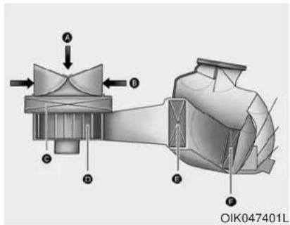
A : Outside air, B : Recirculated air
[C]: Climate control air filter, [D]: Blower
[E] : Evaporator core, [F] : Heater core
The cabin air filter is installed behind the glove box. It filters the dust or other pollutants that enter the vehicle through the heating and air conditioning system.
Have the cabin air filter replaced by an authorized HYUNDAI dealer according to the maintenance schedule. If the vehicle is being driven in severe conditions such as dusty or rough roads and/or if transporting pets or occupants smoke inside the vehicle, then more frequent cabin air filter inspections and changes are required.
If the air flow rate suddenly decreases, the system should be checked at an authorized HYUNDAI dealer.
Checking the amount of air conditioner refrigerant and compressor lubricant
When the amount of refrigerant is low, the performance of the air conditioning is reduced. Overfilling also reduces the performance of the air conditioning system.
Therefore, if abnormal operation is found, have the system inspected by an authorized HYUNDAI dealer.
NOTICE
It is important that the correct type and amount of oil and refrigerant is used. Otherwise, damage to the compressor and abnormal system operation may occur.
WARNING

Because the refrigerant is at very high pressure, the air conditioning system should only be serv-
iced by trained and certified technicians. It is important that the correct type and amount of oil and refrigerant is used, otherwise damage to the vehicle and personal injury may occur.
The air conditioning system should be serviced by an authorized HYUNDAI dealer.
Air Conditioning refrigerant label
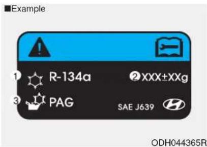
The actual Air Conditioning refrigerant label in the vehicle may differ from the illustration.
Each symbols and specification on air conditioning refrigerant label means as below :
- Classification of refrigerant
- Amount of refrigerant
- Classification of Compressor lubricant
Refer to chapter 8 for more detail location of the air conditioning refrigerant label.
WINDSHIELD DEFROSTING AND DEFOGGING
WARNING
Windshield heating
Do not use the 🚫 or 📋 position during cooling operation in extremely humid weather. The difference between the temperature of the outside air and that of the windshield could cause the outer surface of the windshield to fog up, causing loss of visibility could cause an accident resulting in serious injury or death. In this case, set the mode selection knob or button to the ⏻ position and fan speed control knob or button to a lower speed.
- For maximum defrost performance, set the temperature control knob to the highest temperature setting (rotated all the way to the right) and the fan speed control to the highest setting.
- If warm air to the floor is desired while defrosting or defogging, set the mode to the floor-defrost position.
- Before driving, clear all snow and ice from the windshield, rear window, side view mirrors, and all side windows.
- Clear all snow and ice from the hood and air inlet in the cowl grill to improve heater and defroster efficiency and to reduce the probability of fogging up the inside of the windshield.
NOTICE
If the engine temperature is still cold after starting, then a brief engine warm up period may be required for the vented air flow to become warm or hot.
Manual Climate Control System
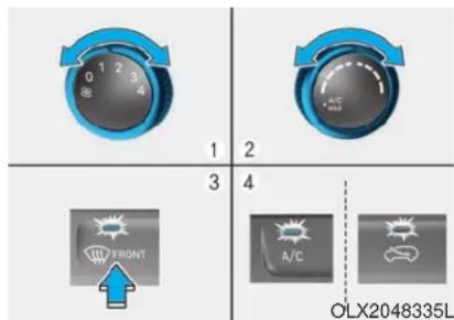
To defog inside windshield
- Select any fan speed except "0" position.
- Select the desired temperature.
- Select 📋 the 📋 or position.
- Fresh mode will be selected automatically. Additionally, the air conditioning will automatically operate if the mode is selected to the position.
Check to make sure the A/C is ON. If the A/C ON LED is not illuminated, press the A/C button once to turn the air conditioner ON.
Check to make sure the air intake control is in Fresh mode. If the air intake control LED is illuminated, press the button once to enable Fresh mode (LED OFF).
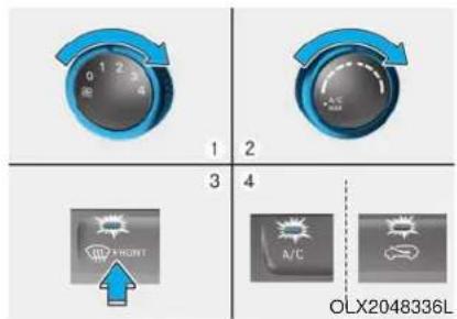
To defrost outside windshield
- Set the fan speed to the highest setting (knob rotated all the way to the right).
- Set the temperature control to the highest temperature setting.
- Select the position.
- Fresh mode (Recirculation OFF) and A/C ON will automatically be selected.
Automatic Temperature Control System (if equipped)
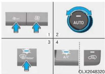
To defog inside windshield
- Select the desired fan speed.
- Select the desired temperature.
- Press the defroster button ( )
- Fresh mode will be selected automatically.
Check to make sure the air intake control is in Fresh mode. If the air intake control LED is illuminated, press the button once to enable Fresh mode (LED OFF).
If the position is selected, the fan speed is automatically increased.
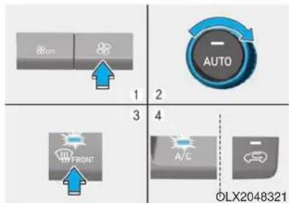
To defrost outside windshield
- Set the fan speed to the highest position.
- Set the temperature to the extreme hot (HI) position.
- Press the defroster button ( )
- The outside (fresh) air position will be selected automatically.
If the position is selected, lower fan speed is adjusted to a higher fan speed.
Defogging logic
To reduce the probability of fogging up the inside of the windshield, the air intake or air conditioning are controlled automatically according to certain conditions such as positions. To cancel or reset the defogging logic, do the following.
Manual climate control system
- Turn the ignition switch to the ON position.
- Press the defroster button (☐)
- Press the air intake control button at least 5 times within 3 seconds.
The LED indicator on the air intake button will blink 3 times to indicate that the defogging logic has been disabled.
Repeat the steps again to re-enable the defogging logic.
If the battery has been discharged or disconnected, it resets to the defog logic status.
Automatic climate control system
- Turn the ignition switch to the ON position.
- Press the defroster button ( )
- While pressing the air conditioning button (A/C), press the air intake control button at least 5 times within 3 seconds.
The Automatic Climate Control information screen will blink 3 times to indicate that the defogging logic has been disabled.
Repeat the steps again to re-enable the defogging logic.
If the battery has been discharged or disconnected, it resets to the defog logic status.
Auto Defogging System (Additional Feature with Automatic Temperature Control System) (if equipped)

natural_image
Diagram of a car's rearview mirror system with an inset showing the mirror and a dotted line indicating alignment (no text or symbols present)Auto defogging helps reduce the possibility of fogging up the inside of the windshield by automatically sensing the moisture on inside the windshield. The auto defogging system operates when the heater or air conditioning is on.
i Information
The auto defogging system may not operate normally, when the outside temperature is below 14 °F (-10 °C).

When the Auto Defogging System operates, the indicator will illuminate.
If a high amount of humidity is detected in the vehicle, the Auto Defogging System will be enabled. The following steps will be performed automatically:
Step 1) The A/C button will turn ON.
Step 2) The air intake control will change to Fresh mode.
Step 3) The mode will be changed to defrost to direct airflow to the windshield.
Step 4) The fan speed will be set to MAX.
If the air conditioning is off or recirculated air position is manually selected while Auto Defogging System is ON, the Auto Defogging System Indicator will blink 3 times to signal that the manual operation has been canceled.
To cancel or reset the Auto Defogging System
Press the front windshield defroster button for 3 seconds when the ignition switch is in the ON position. When the Auto Defogging System is canceled, the ADS OFF symbol will blink 3 times and ADS OFF will be displayed on the climate control information screen.
When the Auto Defogging System is reset, the ADS OFF symbol will blink 6 times without a signal.
i Information
- When the air conditioning is turned on by Auto defogging system, if you try to turn off the air conditioning, the indicator will blink 3 times and the air conditioning will not be turned off.
- To maintain the effectiveness and efficiency of the Auto Defogging System, do not select Recirculation mode while the system is operating.
- When the Auto Defogging System is operating, the fan speed adjustment button, the temperature adjustment knob, and the air intake control button are all disabled.
NOTICE
Do not remove the sensor cover located on the upper end of the windshield glass.
Damage to system parts could occur and may not be covered by your vehicle warranty.
Rear Window Defroster
NOTICE
To prevent damage to the rear window defroster conducting elements bonded to the inside surface of the rear window, never use sharp instruments or window cleaners containing abrasives to clean the window.
If you want to defrost and defog the front windshield, refer to the "Windshield Defrosting and Defogging" section in this chapter.
The defroster heats the window to remove frost, fog and thin ice from the interior and exterior of the rear window, while the engine is running.
- To activate the rear window defroster, press the rear window defroster button located in the center control panel. The indicator on the rear window defroster button illuminates when the defroster is ON.
- To turn off the defroster, press the rear window defroster button again.
i Information
- If there is heavy accumulation of snow on the rear window, brush it off before operating the rear defroster.
- The rear window defroster automatically turns off after approximately 20 minutes or when the ignition switch is in the LOCK/OFF position.
Side view mirror defroster
If your vehicle is equipped with the side view mirror defrosters, they will operate at the same time you turn on the rear window defroster.
CLIMATE CONTROL ADDITIONAL FEATURES
Cluster ionizer (if equipped)
When the ignition switch is in the ON position, the clean air function turns on automatically.
Also, the clean air function turns off automatically, when the ignition switch is in the OFF position.
Automatic Ventilation (if equipped)
When the ignition switch is in the ON position or when the engine is running and temperature is below 59^ F ( 15^ C) with the recirculation mode selected more than three to five minutes, the air intake position will automatically change to fresh mode.
To cancel or reset the Automatic Ventilation
When the air conditioning system is on, select Face Level mode and press the recirculation mode button five times within three seconds while pressing A/C button.
When the Automatic Ventilation feature is enabled, the recirculation button LED indicator will blink 6 times.
When the Automatic Ventilation feature is disabled, the recirculation button LED indicator will blink 3 times.
Sunroof Inside Air Recirculation (if equipped)
When the heater or air conditioning system is on with the sunroof opened, the fresh mode will be automatically selected. If you press the recirculation mode button with the sunroof open, recirculation mode activate but will only remain enabled for 3 minutes. After 3 minutes the air intake control will revert back to Fresh mode.
When the sunroof is closed, the air intake position will return to the original position that was selected.
STORAGE COMPARTMENT
WARNING
Never store cigarette lighters, propane cylinders, or other flammable/explosive materials in the vehicle. These items may catch fire and/or explode if the vehicle is exposed to hot temperatures for extended periods.
WARNING
ALWAYS keep the storage compartment covers closed securely while driving. Items inside your vehicle are moving as fast as the vehicle. If you have to stop or turn quickly, or if there is a crash, the items may fly out of the compartment and may cause an injury if they strike the driver or a passenger.
NOTICE
To avoid possible theft, do not leave valuables in the storage compartments.
Center Console Storage
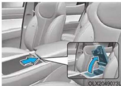
natural_image
Interior view of a car showing the seat, dashboard, and seatbelt (no text or symbols visible)To open :
Grab and hold the latch (1) on the arm rest then lift the lid.
Glove Box
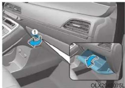
natural_image
Interior view of a car showing the side panel and rearview seatbelt (no text or symbols visible)To open:
Pull the lever (1).
WARNING
ALWAYS close the glove box door after use.
An open glove box door can cause serious injury to the passenger in an accident, even if the passenger is wearing a seat belt.
Luggage Tray (if equipped)
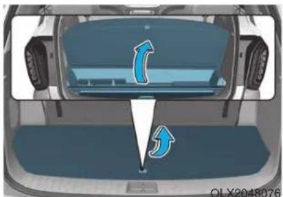
natural_image
Top-down view of a car trunk with visible airflow arrows indicating direction (no text or symbols)You can place a first aid kit, a reflector triangle (front tray), tools, etc. in the box for easy access.
- Grasp the handle on the top of the cover and lift it.
INTERIOR FEATURES
Cup Holder
Front
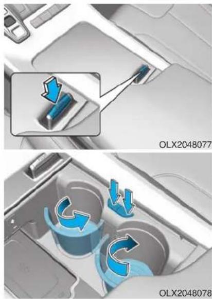
natural_image
Interior view of a car showing a lift valve and a cup with blue arrows indicating flow or movement (no text or symbols)Cups or small beverages cups may be placed in the cup holders.
Push the button and the cover opens. Push the buttons and the cup supporter protrudes from the front console. Push in the cup supporter securely after use.

CAUTION
Do not place thin objects (coin, card etc.) on the cover. These may fall into the inside when the cover is operated.
Rear ( 2^nd row, 3^rd row)
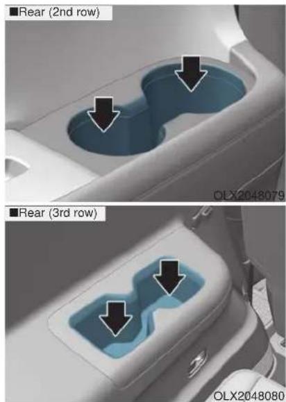
Cups or small beverages cups may be placed in the cup holders.
Rear ( 2^nd row, 8 passengers vehicle)
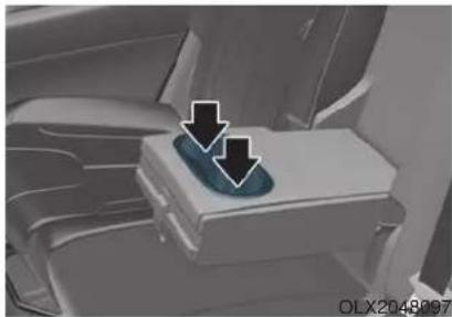
natural_image
Interior view of a car showing a car seat with a blue tray and two black arrows pointing to the seat (no text or symbols visible)Pull the armrest down to use the cup holders.
WARNING
- Avoid abrupt starting and braking when the cup holder is in use to prevent spilling your drink. If hot liquid spills, you could be burned. Such a burn to the driver could cause loss of vehicle control resulting in an accident.
- Do not place uncovered or unsecured cups, bottles, cans, etc., in the cup holder containing hot liquid while the vehicle is in motion. Injuries may result in the event of a sudden stop or collision.
- Only use soft cups in the cup holders. Hard objects can injure you in an accident.
WARNING
Keep cans or bottles out of direct sun light and do not put them in a hot vehicle. It may explode.
NOTICE
- Keep your drinks sealed while driving to prevent spilling your drink. If liquid spills, it may get into the vehicle's electrical/electronic system and damage electrical/electronic parts.
- When cleaning spilled liquids do not use hot air to blow out or dry the cup holder. This may damage the interior.
Conversation mirror
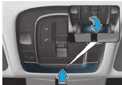
natural_image
Interior view of a car dashboard with control panel and directional arrows indicating movement (no text or symbols)You can see widely the rear view through the conversation mirror.
To open:
Press the cover and the holder will slowly open.
To close:
Push back into position.
Sunvisor
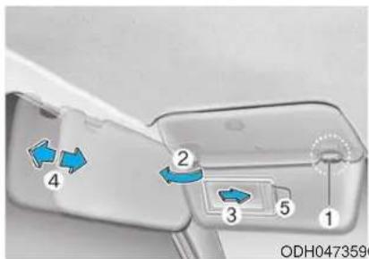
To use the sunvisor, pull it downward.
To use the sunvisor to block the sun from the side window, pull it downward, release it from the bracket (1) and swing it to the side towards the window (2).
To use the vanity mirror, pull down the sunvisor and slide the mirror cover (3).
Adjust the sunvisor forward or backward (4) as needed. Use the ticket holder (5) to hold tickets.
Close the vanity mirror cover securely and return the sunvisor to its original position after use.
WARNING
For your safety, do not block your view when using the sunvisor.
NOTICE 0480741
Do not put several tickets in the ticket holder at one time. This could cause damage to the ticket holder.
Power Outlet
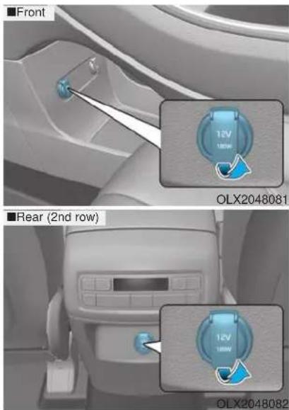
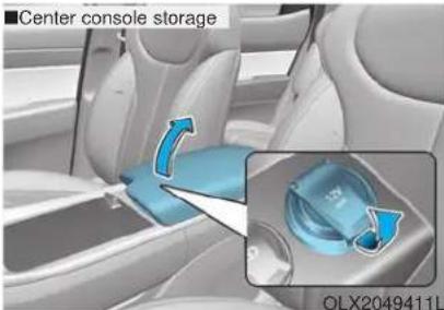
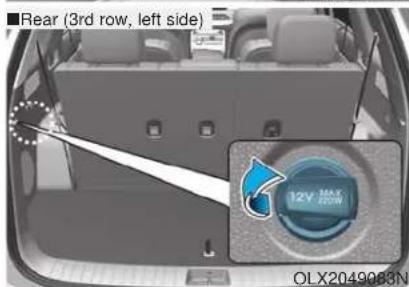
The power outlet is designed to provide power for mobile telephones or other devices designed to operate with vehicle electrical systems. The devices should draw less than 180 W with the engine running.
WARNING
Avoid electrical shocks. Do not place your fingers or foreign objects (pin, etc.) into a power outlet or touch the power outlet with a wet hand.
NOTICE
To prevent damage to the Power Outlets :
- Use the power outlet only when the engine is running and remove the accessory plug after use. Using the accessory plug for prolonged periods of time with the engine off could cause the battery to discharge.
- Only use 12V electric accessories which are less than 180 W in electric capacity.
- Adjust the air-conditioner or heater to the lowest operating level when using the power outlet.
-
Close the cover when not in use.
-
Some electronic devices can cause electronic interference when plugged into a vehicle's power outlet. These devices may cause excessive audio static and malfunctions in other electronic systems or devices used in your vehicle.
- Push the plug in as far as it will go. If good contact is not made, the plug may overheat and the fuse may open.
- Plug in battery equipped electrical/electronic devices with reverse current protection. The current from the battery may flow into the vehicle's electrical/electronic system and cause system malfunction.
AC Inverter (if equipped)
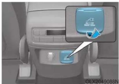
natural_image
Interior view of a car dashboard with a blue control panel and an inset showing a blue 'PULLY HANDLING' button (no text or symbols on the main subject)The AC inverter supplies 115V/150W electric power to operate electric accessories or equipments.
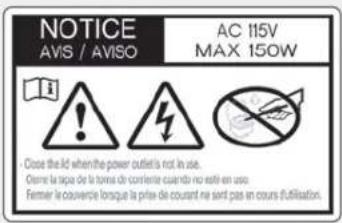
• Rated voltage : AC 115V
• Maximum electric power : 150W
- In order to avoid an electrical system failure, electric shock, etc., be sure to read owner's manual before use.
- Be sure to close the cover except the time of use.
WARNING
To reduce a risk of serious or fatal injuries:
- Do not use a heated electric device such as a coffeepot, toaster, heater, iron, etc.
- Do not insert foreign objects into the outlet and do not touch the outlet as you may get shocked.
- Do not let children touch the AC inverter.
NOTICE
- To prevent the battery from being discharged, do not use the AC inverter while the engine is not running.
- When not using the AC inverter, make sure to close the AC inverter cover.
• After using an electric accessory or equipment, pull the plug out. Leaving the accessory or equipment plugged in for a long time may cause battery discharge. - Do not use an electric accessory or equipment the power consumption of which is greater than 150W (115V).
- Some electric accessories or equipments can cause electronic interference. It may cause excessive audio noise and malfunctions in other electric systems or devices in the vehicle.
-
Do not use broken electric accessories or equipments, which may damage the AC inverter and electrical systems of the vehicle.
-
Do not use two or more electric accessories or equipments at the same time. It may cause damage to the electrical systems of the vehicle.
- When the input voltage is lower, outlet LED will blink and the AC inverter will turn off automatically. If the input voltage goes up to normal, the AC inverter will turn on again.
- Do not use two or more electric accessories or equipments at the same time. It may cause damage to the electrical systems of the vehicle.
- When the input voltage is lower, outlet LED will blink and the AC inverter will turn off automatically. If the input voltage goes up to normal, the AC inverter will turn on again.
USB Charger (if equipped)
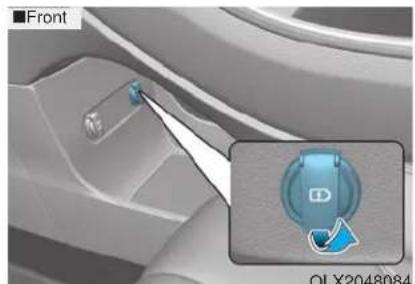
natural_image
Close-up of a car interior showing a front-mounted switch and a highlighted circular component (no text or symbols visible)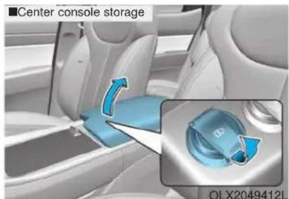
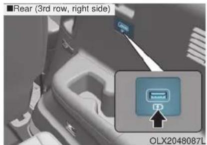
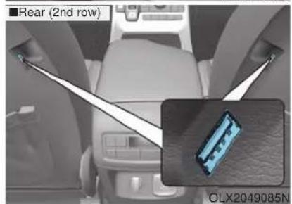
natural_image
Interior view of a car showing rear seatbelt and a close-up inset of a vehicle component (no text or symbols visible)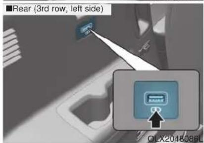
The battery charging state may be monitored on the electrical device. Disconnect the USB cable from the USB port after use.
The USB charger is designed to recharge batteries of small size electrical devices using a USB cable.
The electrical devices can be recharged when the ignition switch is ON. Insert the USB charger into the USB port, and re-charge a smart phone or a tablet PC.
- A smart phone or a tablet PC may get warmer during the re-charging process. It does not indicate any malfunction with the charging system.
- A smart phone or a tablet PC, which adopts a different re-charging method, may not be properly re-charged. In this case, use an exclusive charger of your device.
- The charging terminal is only to recharge a device. Do not use the charging terminal either to turn ON an audio or to play media.
Wireless Cellular Phone Charging System (if equipped)
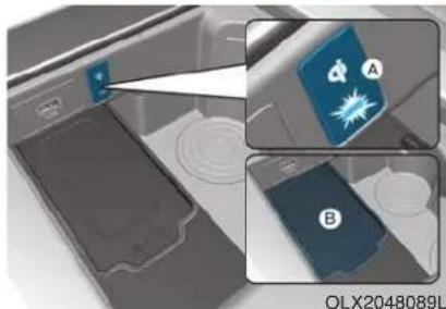
natural_image
Close-up of a car interior with two labeled panels (A and B) showing internal components and a warning icon, no readable text or symbols present.A: Indicator light, B: Charging pad
On certain models, the vehicle comes equipped with a wireless cellular phone charger.
The system is available when all doors are closed, and when the ignition switch is ON.
To charge a cellular phone
The wireless cellular phone charging system charges only the Qi-enabled cellular phones (Read the label on the cellular phone accessory cover or visit your cellular phone manufacturer's website to check whether your cellular phone supports the Qi technology.
The wireless charging process starts when you put a Qi-enabled cellular phone on the wireless charging unit.
- Remove other items, including the smart key, from the wireless charging unit. If not, the wireless charging process may be interrupted. Place the cellular phone on the center of the charging pad (
- The indicator light is orange when the cellular phone is charging. The indicator light turns green when phone charging is complete.
- You can turn ON or OFF the wireless charging function in the user settings mode on the instrument cluster. For further information, refer to the "LCD Display Modes" in this chapter.
If your cellular phone is not charging:
- Slightly change the position of the cellular phone on the charging pad.
- Make sure the indicator light is orange.
The indicator light will blink orange for 10 seconds if there is a malfunction in the wireless charging system.
In this case, temporarily stop the charging process, and re-attempt to charge your cellular phone again.
The system warns you with a message on the LCD display if the cellular phone is still on the wireless charging unit after the engine is turned OFF and the front door is opened.
i Information
For some manufacturers' cellular phones, the system may not warn you even though the cellular phone is left on the wireless charging unit. This is due to the particular characteristic of the cellular phone and not a malfunction of the wireless charging.
NOTICE
- The wireless cellular phone charging system may not support certain cellular phones, which are not verified for the Qi specification (Qi)
- When placing your cellular phone on the charging mat, position the phone in the middle of the mat for optimal charging performance. If your cell phone is off to the side, the charging rate may be less and in some cases the cell phone may experience higher heat conduction.
- In some cases, the wireless charging may stop temporarily when the Remote Key or Smart Key is used, either when starting the vehicle or locking/unlocking the doors, etc.
-
When charging certain cellular phones, the charging indicator may not change to green when the cell phone is fully charged.
-
The wireless charging process may temporarily stop, when temperature abnormally increases inside the wireless cellular phone charging system. Stop the charging cellular phone and wait until temperature falls to a certain level.
- The wireless charging process may temporarily stop when there is any metallic item, such as a coin, between the wireless cellular phone charging system and the cellular phone.
- When charging some cellular phones with a self-protection feature, the wireless charging speed may decrease and the wireless charging may stop.
- If the cellular phone has a thick cover, the wireless charging may not be possible.
- If the cell phone is not completely contacting the charging pad, wireless charging may not operate properly.
- Some magnetic items like credit cards, phone cards or rail tickets may be damaged if left with the cellular phone during the charging process.
- When any cellular phone without a wireless charging function or a metallic object is placed on the charging pad, a small noise may sound. This small sound is due to the vehicle discerning compatibility of the object placed on the charging pad. It does not affect your vehicle or the cellular phone in any way.
i Information
If the ignition switch is in the OFF position, the charging also stops.
i Information
This device complies with part 15 of the FCC Rules.
Operation is subject to the following two conditions:
- This device may not cause harmful interference, and
- This device must accept any interference received, including interference that may cause undesired operation.
Clock
WARNING
Do not attempt to adjust the clock while driving. Doing so may result in distracted driving which may lead to an accident involving personal injury or death.
You can set the time through info-tainment system.
Coat Hook
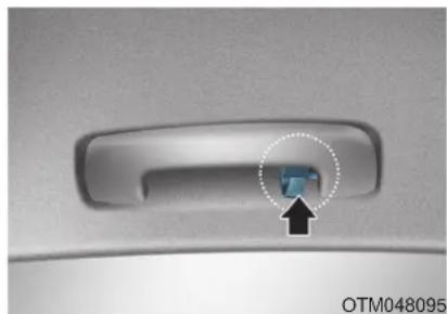
natural_image
Close-up of a car door handle with a blue button and an arrow pointing to it, no visible text or symbols.These hangers are not designed to hold large or heavy items.
WARNING
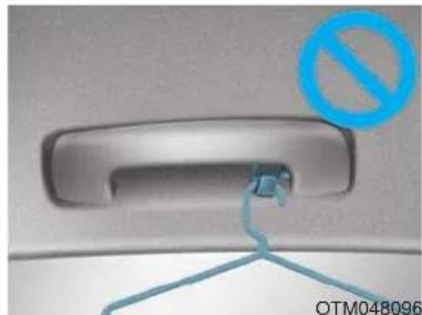
natural_image
Close-up of a car door handle with a blue prohibition symbol overlay (no text or symbols on the main subject)Do not hang other objects such as hangers or hard objects except clothes. Also, do not put heavy, sharp or breakable objects in the clothes pockets. In an accident or when the curtain air bag is inflated, it may cause vehicle damage or personal injury.
Floor Mat Anchor(s)
ALWAYS use the Floor Mat Anchors to attach the floor mats to the vehicle. The anchors on the front floor carpet keep the floor mats from sliding forward.
WARNING
Do not overlay additional mats or liners over the floor mats. If using All Weather mats, remove the carpeted floor mats before installing them. Only use floor mats designed to connect to the anchors.
WARNING
The following must be observed when installing ANY floor mat to the vehicle.
- Ensure that the floor mats are securely attached to the vehicle's floor mat anchor(s) before driving the vehicle.
- Do not use ANY floor mat that cannot be firmly attached to the vehicle's floor mat anchors.
- Do not stack floor mats on top of one another (e.g. all-weather rubber mat on top of a carpeted floor mat). Only a single floor mat should be installed in each position.
IMPORTANT - Your vehicle was manufactured with driver's side floor mat anchors that are designed to securely hold the floor mat in place. To avoid any interference with pedal operation, HYUNDAI recommends that the HYUNDAI floor mat designed for use in your vehicle be installed.
Luggage Net Holder (if equipped)
To keep items from shifting in the luggage compartment, you can use the 4 holders located in the luggage board to attach the luggage net.
Make sure the luggage net is securely attached to the holders in the luggage board.
WARNING
Avoid eye injury. DO NOT over-stretch the luggage net. ALWAYS keep your face and body out of the luggage net's recoil path. DO NOT use the luggage net when the strap has visible signs of wear or damage.
Use the luggage net to keep only light items from shifting in the luggage compartment.
Cargo Security Screen (if equipped)
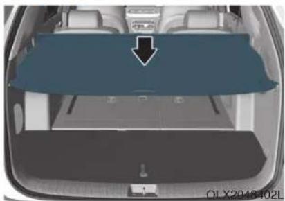
natural_image
Top-down view of a car trunk with a blue cover panel and arrow pointing to the side (no text or symbols visible)Use the cargo security screen to cover items stored in the cargo area.
To use the cargo security screen
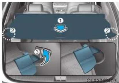
- Pull the cargo security screen towards the rear of the vehicle by the handle (1).
- Insert the guide pin (2) into the guide (3).
i Information
Pull out the cargo security screen with the handle in the center to prevent the guide pin from falling out of the guide.
When the cargo security screen is not in use:
-
Pull the cargo security screen backward and up to release it from the guides.
-
The cargo security screen will automatically slide back in.
i Information
The cargo security screen may not automatically slide back in if the cargo security screen is not fully pulled out. Pull the cargo screen out all the way and then slowly allow the screen to retract back into the mechanism.
To remove the cargo security screen
-
Push one side of the cargo screen inward to compress the spring mechanism and release the screen from the vehicle.
-
While the mechanism is compressed, pull out the cargo security screen.
-
Open the luggage tray and keep the cargo security screen in the tray.
To remove the cargo security screen from the luggage tray
natural_image
3D rendering of a boat hull with blue airflow arrow indicating direction (no text or symbols)- Pull up the screen board.
natural_image
Illustration of a hand pressing down on a mechanical component with an arrow indicating force (no text or symbols)- Push in the guide pin.
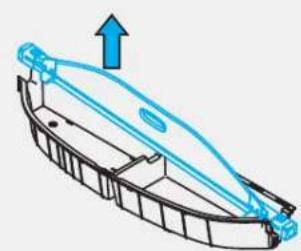
natural_image
Diagram of a boat hull with an upward arrow indicating direction (no text or symbols)OTLE055154
- While pushing the guide pin, pull out the cargo security screen.
NOTICE
Since the cargo security screen may be damaged or malformed, do not put luggage on it when it is used.
WARNING
- Do not place objects on the cargo security screen. Such objects may be thrown about inside the vehicle and possibly injure vehicle occupants during an accident or when braking.
- Never allow anyone to ride in the luggage compartment. It is designed for luggage only.
- Maintain the balance of the vehicle and locate the weight as forward as possible.
Side Curtain (if equipped)
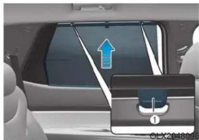
natural_image
Interior view of a car showing a blue arrow pointing upward and a control panel labeled '1' (no text or symbols on the main subject)To use the side curtain:
- Lift the curtain by the curtain knob (1).
- Hang the curtain on both sides of the hook.
CAUTION
• Always hang both sides of the curtain on the hook. This could cause damage to the side curtain if only one side of the curtain is hooked.
- Do not let any foreign material get in between the vehicle and side curtain. The side curtain may not be lifted up.
- Do not hang other objects except the side curtain.
- When using the side curtain and turning it back into place, pulling the curtain or applying force may cause damage to the side curtain. When lowering the curtain, be sure to place the curtain knob downward in that state and slowly return it to the position.
EXTERIOR FEATURES
Roof Side Rails (if equipped)
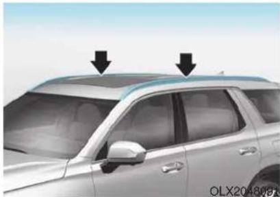
natural_image
Side view of a silver SUV with two black arrows pointing to the roof (no text or symbols visible)If your vehicle comes equipped with roof side rails, then roof rack crossbars can be installed on top of your vehicle.
The roof rack crossbars are an accessory and are available at your local HYUNDAI dealer.
NOTICE
If the vehicle is equipped with a sunroof, be sure not to position cargo onto the roof rack in such a way that it could interfere with sunroof operation.
NOTICE
- When carrying cargo on the roof rack, take the necessary precautions to make sure the cargo does not damage the roof of the vehicle.
- When carrying large objects on the roof rack, make sure they do not exceed the overall roof length or width.
WARNING
- The following specification is the maximum weight that can be loaded onto the roof rack. Distribute the load as evenly as possible onto the roof rack and secure the load firmly. Loading cargo or luggage in excess of the specified weight limit on the roof rack may damage your vehicle.
ROOF RACK
220 lbs. (100kg) EVENLY DISTRIBUTED
- The vehicle center of gravity will be higher when items are loaded onto the roof rack. Avoid sudden starts, braking, sharp turns, abrupt maneuvers or high speeds that may result in loss of vehicle control or rollover resulting in an accident.
• Always drive slowly and turn corners carefully when carrying items on the roof rack. Severe wind updrafts, caused by passing vehicles or natural causes, can cause sudden upward pressure on items loaded on the roof rack. This is especially true when carrying large, flat items such as wood panels or mattresses. This could cause the items to fall off the roof rack and cause damage to your vehicle or others around you.
• To prevent damage or loss of cargo while driving, check frequently before or while driving to make sure the items on the roof rack are securely fastened.
Multimedia System
Infotainment System....4-2
USB Port....4-2
Antenna 4-2
Steering Wheel Audio Controls....4-3
Bluetooth® Wireless Technology 4-4
Audio (Display Audio) / Video /
Navigation System (AVN)....4-4
INFOTAINMENT SYSTEM
NOTICE
- If you install an aftermarket HID head lamp, your vehicle's audio and electronic devices may not function properly.
- Prevent chemicals such as perfume, cosmetic oil, sun cream, hand cleaner, and air freshener from contacting the interior parts because they may cause damage or discoloration.
USB port
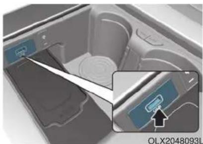
natural_image
Interior view of a medical device showing internal components and a close-up of a device with an arrow pointing to it (no visible text or symbols)You can use a USB port to plug in a USB device.
i Information
When using a portable audio device connected to the power outlet, noise may occur during playback. If this happens, use the portable audio device's power source.
Antenna
Pole antenna (if equipped)
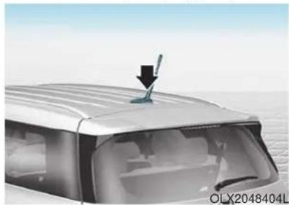
natural_image
Top-down view of a car's roof with a black arrow pointing to the roof (no text or symbols visible)Your vehicle uses a roof antenna to receive AM or/and FM broadcast signals. This antenna pole is removable. To remove the roof antenna pole, turn it counterclockwise.
To install the roof antenna pole, turn it clockwise.
NOTICE
Before entering a place with a low height clearance or a car wash, remove the antenna pole by rotating it counterclockwise. If not, the antenna may be damaged.
- When reinstalling your roof antenna, it is important that it is fully tightened and adjusted to the upright position to ensure proper reception.
- When cargo is loaded on the roof rack, do not place the cargo near the antenna pole to ensure proper reception.
Shark fin antenna (if equipped)
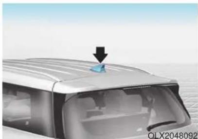
natural_image
Exterior view of a modern car with a blue roof and black arrow indicating a component (no text or symbols)The shark fin antenna will receive the AM, FM broadcast signals and transmit data.
Steering Wheel Audio Control
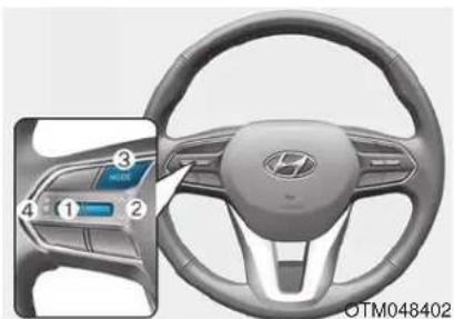
NOTICE
Do not operate multiple audio remote control buttons simultaneously.
VOLUME (VOL + / - ) (1)
- Press the VOLUME (+) switch up to increase volume.
- Press the VOLUME (-) switch down to decrease volume.
SEEK/PRESET ( ∥ ) (2) √
If the SEEK/PRESET switch is pressed up or down and held for 0.8 second or more, it will function in the following modes:
RADIO mode
It will function as the AUTO SEEK select button. It will SEEK until you release the button.
MEDIA mode
It will function as the FF/RW button.
If the SEEK/PRESET switch is pressed up or down, it will function in the following modes:
RADIO mode
It will function as the PRESET STATION UP/DOWN button.
MEDIA mode
It will function as the TRACK UP/DOWN button.
MODE (3)
Press the MODE button to select Radio and Media.
MUTE (呎(4)
- Press the MUTE button to mute the sound.
- Press the MUTE button again to activate the sound.
i Information
Detailed information for audio control buttons are described in the separately supplied manual with the vehicle.
Bluetooth® Wireless Technology
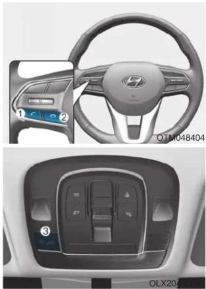
natural_image
Interior view of a car dashboard and steering wheel, showing dashboard controls and control panel (no text or symbols visible)(1) Call / Answer button
(2) Call end button
(3) Microphone
Detailed information for the Bluetooth hands-free is described in a separately supplied manual with the vehicle.
Audio (Display Audio) / Video / Navigation System (if equipped)
Detailed information for the Audio/AVN system is described in a separately supplied manual with the vehicle.
Driving your vehicle
Before Driving 5-5
Before Entering the Vehicle....5-5
Before Starting 5-5
Ignition Switch....5-7
Key Ignition Switch 5-7
Engine Start/Stop Button 5-10
Automatic Transmission 5-15
Automatic transmission operation 5-15
Parking....5-18
LCD display message....5-19
Good driving practices....5-20
Paddle Shifter (Manual Shift Mode) 5-22
Braking system....5-23
Power Brakes....5-23
Disc Brakes Wear Indicator 5-24
Electronic Parking Brake (EPB)....5-24
Auto Hold 5-29
Anti-lock Brake System (ABS) 5-33
Electronic Stability Control (ESC)....5-35
Vehicle Stability Management (VSM)....5-38
Hill-Start Assist Control (HAC) 5-39
Downhill Brake Control (DBC)....5-39
Trailer Stability Assist (TSA)....5-42
Good Braking Practices....5-42
All Wheel Drive (AWD) 5-43
AWD Operation 5-44
LCD display message....5-47
Emergency Precautions....5-48
ISG (Idle Stop and Go) system....5-50
To Activate the ISG System 5-50
To Deactivate the ISG System....5-53
ISG System Malfunction....5-53
Battery Sensor Deactivation 5-54
Drive Mode Integrated Control system
(2WD)....5-55
Drive Mode 5-55
Drive Mode Integrated Control system
(AWD) 5-59
Drive Mode 5-59
Forward Collision-Avoidance Assist (FCA)
system....5-63
System Setting and Operation....5-63
FCA Warning Message and Brake Control ....5-66
FCA Sensor (Front Radar/Front Camera)......5-68
System Malfunction 5-70
Limitations of the System....5-72
Blind-Spot Collision Warning/
Blind-Spot Collision-Avoidance Assist ....5-78
System Description....5-78
System Setting and Operation....5-79
Warning and System Control 5-82
Detecting Sensor (Camera and Radar)....5-84
Limitations of the System....5-87
Rear Cross-Traffic Collision Warning (RCCW)/
Rear Cross-Traffic Collision-Avoidance Assist
(RCCA) 5-92
System Description....5-92
System Setting and Operation....5-93
Warning and System Control 5-95
Detecting Sensor....5-98
Limitations of the System....5-99
Lane Following Assist (LFA) system .....5-103
LFA Setting and Operation 5-104
Warning Message 5-105
Limitations of the System....5-107
Lane Keeping Assist (LKA) system 5-109
LKA System Operation....5-110
Warning Light and Message 5-112
Limitations of the System....5-114
LKA System Function Change 5-116
Driver Attention Warning (DAW) system .....5-117
System Setting and Operation....5-117
Resetting the System....5-118
System Standby....5-119
System Malfunction 5-119
Highway Driving Assist (HDA) system......5-121
System Setting and Operation....5-121
Warning Message 5-124
Smart Cruise Control With Stop &
Go System 5-128
Smart Cruise Control Switch 5-129
Adjusting the Sensitivity of Smart Cruise
Control 5-129
To Convert to Cruise Control Mode 5-130
Smart Cruise Control Speed 5-131
Smart Cruise Control Vehicle-to-Vehicle
Distance....5-135
Sensor to Detect Distance to the
Vehicle Ahead 5-138
Limitations of the System....5-140
Leading Vehicle Departure Alert 5-146
System Setting and Operation....5-146
Special Driving Conditions....5-148
Hazardous Driving Conditions....5-148
Rocking the Vehicle....5-148
Smooth Cornering....5-149
Driving at Night 5-149
Driving in the Rain....5-149
Driving in Flooded Areas....5-150
Highway Driving 5-150
Reducing the Risk of a Rollover 5-151
Winter Driving 5-152
Snow or Icy Conditions....5-152
Winter Precautions....5-154
Trailer Towing....5-156
If you decide to pull a trailer....5-156
Trailer towing equipment 5-158
Driving with a trailer 5-159
Maintenance when trailer towing 5-162
Vehicle Load Limit....5-164
Tire Loading Information Label....5-165
WARNING
Carbon monoxide (CO) gas is toxic. Breathing CO can cause unconsciousness and death.
Engine exhaust contains carbon monoxide which cannot be seen or smelled.
Do not inhale engine exhaust.
If at any time you smell engine exhaust inside the vehicle, open the windows immediately. Exposure to CO can cause unconsciousness and death by asphyxiation.
Be sure the exhaust system does not leak.
The exhaust system should be checked whenever the vehicle is raised to change the oil or for any other purpose. If you hear a change in the sound of the exhaust or if you drive over something that strikes the underneath side of the vehicle, have the exhaust system checked as soon as possible by an authorized HYUNDAI dealer.
Do not run the engine in an enclosed area.
Letting the engine idle in your garage, even with the garage door open, is a hazardous practice. Run the engine only long enough to start the engine and to move the vehicle out of the garage.
Avoid idling the engine for prolonged periods with people inside the vehicle.
If it is necessary to idle the engine for a prolonged period with people inside the vehicle, be sure to do so only in an open area with the air intake set at "Fresh" and fan control set to high so fresh air is drawn into the interior.
Keep the air intakes clear.
To assure proper operation of the ventilation system, keep the ventilation air intakes located in front of the windshield clear of snow, ice, leaves, or other obstructions.
If you must drive with the liftgate open:
Close all windows.
Open instrument panel air vents.
Set the air intake control at "Fresh", the air flow control at "Floor" or "Face", and the fan control set to high.
WARNING
CALIFORNIA PROPOSITION 65 WARNING
Engine exhaust and a wide variety of automobile components including components found in the interior furnishings in a vehicle, contain or emit harmful chemicals known to the State of California to cause cancer and birth defects and reproductive harm. In addition, certain fluids contained in vehicles and certain products of components contain or emit chemicals known to the State of California to cause cancer and birth defects or other reproductive harm.
For more information go to https://www.p65warnings.ca.gov/passenger-vehicle
BEFORE DRIVING
Before Entering the Vehicle
- Be sure all windows, outside mirror(s), and outside lights are clean and unobstructed.
- Remove frost, snow, or ice.
- Visually check the tires for uneven wear and damage.
- Check under the vehicle for any sign of leaks.
- Be sure there are no obstacles behind you if you intend to back up.
Before Starting
- Make sure the hood, the liftgate, and the doors are securely closed and locked.
- Adjust the position of the seat and steering wheel.
- Adjust the inside and outside rearview mirrors.
- Verify all the lights work.
- Fasten your seatbelt. Check that all passengers have fastened their seatbelts.
- Check the gauges and indicators in the instrument panel and the messages on the instrument display when the ignition switch is in the ON position.
- Check that any items you are carrying are stored properly or fastened down securely.
WARNING
To reduce the risk of SERIOUS INJURY or DEATH, take the following precautions:
- ALWAYS wear your seat belt. All passengers must be properly belted whenever the vehicle is moving. For more information, refer to "Seat Belts" in chapter 2.
• Always drive defensively. Assume other drivers or pedestrians may be careless and make mistakes. - Stay focused on the task of driving. Driver distraction can cause accidents.
- Leave plenty of space between you and the vehicle in front of you.
WARNING
NEVER drink or take drugs and drive.
Drinking or taking drugs and driving is dangerous and may result in an accident and SERIOUS INJURY or DEATH.
Drunk driving is the number one contributor to the highway death toll each year. Even a small amount of alcohol will affect your reflexes, perceptions and judgment. Just one drink can reduce your ability to respond to changing conditions and emergencies and your reaction time gets worse with each additional drink.
Driving while under the influence of drugs is as dangerous or more dangerous than driving under the influence of alcohol.
You are much more likely to have a serious accident if you drink or take drugs and drive. If you are drinking or taking drugs, don't drive. Do not ride with a driver who has been drinking or taking drugs. Choose a designated driver or call a taxi.
IGNITION SWITCH
Key Ignition Switch
WARNING
To reduce the risk of SERIOUS INJURY or DEATH, take the following precautions:
- NEVER allow children or any person who is unfamiliar with the vehicle to touch the ignition switch or related parts. Unexpected and sudden vehicle movement can occur.
- NEVER reach through the steering wheel for the ignition switch, or any other control, while the vehicle is in motion. The presence of your hand or arm in this area may cause a loss of vehicle control resulting in an accident.
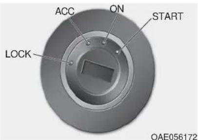
Whenever the front door is opened, the ignition switch will illuminate, provided the ignition switch is not in the ON position. The light will go off immediately when the ignition switch is turned on or go off after about 30 seconds when the door is closed. (if equipped)
WARNING
NEVER turn the ignition switch to the LOCK or ACC position while the vehicle is in motion except in an emergency. This will result in the engine turning off and loss of power assist for the steering and brake systems. This may lead to loss of directional control and braking function, which could cause an accident.
Before leaving the driver's seat, always make sure the gear is in P (Park) position, apply the parking brake, and turn ignition switch to the LOCK position.
Unexpected vehicle movement may occur if these precautions are not followed.
Key ignition switch positions
| Switch Position | Action Notice | |
| LOCK | To turn the ignition switch to the LOCK position, put the key in at the ACC position and turn the key towards the LOCK position.The ignition key can be removed in the LOCK position.The shift lever must be in the P (Park) position. | |
| ACC | Some of the electrical accessories are usable. | |
| ON | This is the normal key position when the engine has started.All features and accessories are usable.The warning lights can be checked when you turn the ignition switch from ACC to ON. | Do not leave the ignition switch in the ON position when the engine is not running in order to prevent the battery from discharging. |
| START | To start the engine, turn the ignition switch to the START position. The switch returns to the ON position when you let go of the key. | The engine will crank until you release the key. |
Starting the engine
WARNING
Always wear appropriate shoes when operating your vehicle. Unsuitable shoes, such as high heels, ski boots, sandals, flip-flops, etc., may interfere with your ability to use the brake and accelerator pedals.
- Make sure the parking brake is applied.
- Make sure the gear is in P (Park).
- Depress the brake pedal.
- Turn the ignition switch to the START position. Hold the key (maximum of 10 seconds) until the engine starts and release it.
i Information
- It is best to maintain a moderate engine speed until the vehicle engine comes up to normal operating temperature. Avoid harsh or abrupt acceleration or deceleration while the engine is still cold.
- Whether the engine is cold or warm, always start the vehicle with your foot on the brake pedal. Do not depress the accelerator while starting the vehicle. Do not rev the engine while warming it up.
NOTICE
To prevent damage to the vehicle:
- Do not hold the ignition key in the START position for more than 10 seconds. Wait 5 to 10 seconds before trying again.
- Do not push or tow your vehicle to start the engine.
Turning off the engine
- Stop the vehicle and depress the brake pedal fully.
- Shift the gear to P (Park).
- Turn the ignition switch to the off position and apply the parking brake.
Engine Start/Stop Button
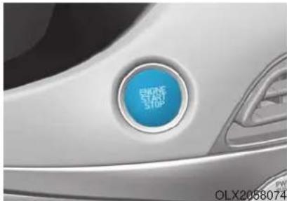
natural_image
Close-up of a car's front bumper with a blue circular button labeled 'ENGINE START STOP' (no additional text or symbols visible)Whenever the front door is opened, the Engine Start/Stop button will illuminate and will go off 30 seconds after the door is closed.
WARNING
To reduce risk of serious injury or death, NEVER allow children or any person who is unfamiliar with the vehicle to touch the Engine Start/Stop button or related parts. Unexpected and sudden vehicle movement can occur.
WARNING
To turn the engine off in an emergency:
Press and hold the Engine Start/Stop button for more than two seconds OR rapidly press and release the Engine Start/Stop button three times (within three seconds).
If the vehicle is still moving, you can restart the engine without depressing the brake pedal by pressing the Engine Start/Stop button with the gear in the N (Neutral) position.
WARNING
- NEVER press the Engine Start/Stop button while the vehicle is in motion except in an emergency. This will result in the engine turning off and loss of power assist for the steering and brake systems.
This may lead to loss of directional control and braking function, which could cause an accident.
- Before leaving the driver's seat, always make sure the gear is in the P (Park) position, set the parking brake, press the Engine Start/ Stop button to the OFF position, and take the Smart Key with you. Unexpected vehicle movement may occur if these precautions are not followed.
- NEVER reach through the steering wheel for the Engine Start/Stop button or any other control while the vehicle is in motion. The presence of your hand or arm in this area may cause a loss of vehicle control resulting in an accident.
Engine Start/Stop button positions
| Button Position Action Notice | ||
| OFF | To turn off the engine, press the Engine Start/Stop button with the gear in P (Park).When you press the Engine Start/Stop button without the gear in P (Park), the Engine Start/Stop button does not turn to the OFF position, but turns to the ACC position. | |
| ACC | Press the Engine Start/Stop button when the button is in the OFF position without depressing the brake pedal.Some of the electrical accessories are usable. | If you leave the Engine Start/Stop button in the ACC position with the gear in P (Park) for more than one hour, the battery power will turn off automatically to prevent the battery from discharging. |
| ON | Press the Engine Start/Stop button while it is in the ACC position without depressing the brake pedal.The warning lights can be checked before the engine is started. | Do not leave the Engine Start/Stop button in the ON position when the engine is not running to prevent the battery from discharging. |
| START | To start the engine, depress the brake pedal and press the Engine Start/Stop button with the gear in the P (Park) or in the N (Neutral) position.For your safety, start the engine with the gear in the P (Park) position. | If you press the Engine Start/Stop button without depressing the brake pedal, the engine does not start and the Engine Start/Stop button changes as follows:OFF →ACC →ON →OFFHowever, the engine may start if you depress the brake pedal within 0.5 second after pressing the Engine Start/Stop button from the OFF position. |
Starting the engine
WARNING
• Always wear appropriate shoes when operating your vehicle. Unsuitable shoes, such as high heels, ski boots, sandals, flip-flops, etc., may interfere with your ability to use the brake and accelerator pedals.
- Do not start the vehicle with the accelerator pedal depressed. The vehicle can move and lead to an accident.
- Wait until the engine rpm is normal. The vehicle may suddenly move if the brake pedal is released when the rpm is high.
i Information
- The engine will start by pressing the Engine Start/Stop button, only when the smart key is in the vehicle.
- Even if the smart key is in the vehicle, if it is far away from the driver, the engine may not start.
-
When the Engine Start/Stop button is in the ACC or ON position, if any door is open, the system checks for the smart key. If the smart key is not in the vehicle, the " indicator will blink and the warning "Key not in vehicle" will come on and if all doors are closed, the chime will also sound for about 5 seconds. Keep the smart key in the vehicle when using the ACC position or if the vehicle engine is ON.
-
Always carry the smart key with you.
- Make sure the parking brake is applied.
- Make sure the gear is in P (Park).
- Depress the brake pedal.
- Press the Engine Start/Stop button.
i Information
- Do not wait for the engine to warm up while the vehicle remains stationary. Start driving at moderate engine speeds. (Aggressive accelerating and decelerating should be avoided.)
• Always start the vehicle with your foot on the brake pedal. Do not depress the accelerator while starting the vehicle. Do not rev the engine while warming it up.
To prevent damage to the vehicle:
- If the engine stalls while you are in motion, do not attempt to shift the gear to the P (Park) position. If traffic and road conditions permit, you may put the gear in the N (Neutral) position while the vehicle is still moving and press the Engine Start/Stop button in an attempt to restart the engine.
- Do not push or tow your vehicle to start the engine.
NOTICEN
To prevent damage to the vehicle: When the stop lamp switch fuse is blown, you can't start the engine normally. Replace the fuse with a new one. If you are not able to replace the fuse, you can start the engine by pressing and holding the Engine Start/Stop button for 10 seconds with the Engine Start/Stop button in the ACC position.
Do not press the Engine Start/Stop button for more than 10 seconds except when the stop lamp switch fuse is blown.
For your safety always depress the brake pedal before starting the engine.
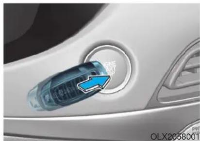
natural_image
Close-up of a car's side panel with a blue arrow pointing to the center (no visible text or symbols)i Information
If the smart key battery is weak or the smart key does not work correctly, you can start the engine by pressing the Engine Start/Stop button with the smart key in the direction of the picture above.
Turning off the engine
- Stop the vehicle and depress the brake pedal fully.
- Shift the gear to P (Park).
- Press the Engine Start/Stop button to the off position and apply the parking brake.
AUTOMATIC TRANSMISSION
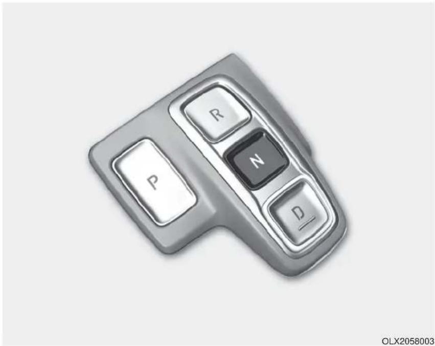
natural_image
Close-up of a gray automotive keyboard key with labeled buttons (R, P, N, D) and model number OLX2058003 at bottom right (no text on main body)Automatic transmission operation
The automatic transmission has eight forward speeds and one reverse speed.
The individual speeds are selected automatically in the D (Drive) position.
Transmission ranges
The indicator in the instrument cluster displays the gear position when the ignition switch is in the ON position.
WARNING
To reduce the risk of serious injury or death:
- ALWAYS check the surrounding areas near your vehicle for people, especially children, before shifting a vehicle into D (Drive) or R (Reverse).
- Before leaving the driver's seat, always make sure the gear is in the P (Park) position, then set the parking brake, and place the ignition switch in the LOCK/OFF position. Unexpected and sudden vehicle movement can occur if these precautions are not followed.
- Do not use the engine brake (shifting from a high gear to lower gear) rapidly on slippery roads. The vehicle may slip causing an accident.
P (Park)
Always come to a complete stop before shifting into P (Park).
To shift from P (Park), you must depress firmly on the brake pedal and make sure your foot is off the accelerator pedal.
The gear must be in P (Park) before turning the engine off.
WARNING
- Shifting into P (Park) while the vehicle is in motion may cause you to lose control of the vehicle.
• After the vehicle has stopped, always make sure the gear is in P (Park), apply the parking brake, and turn the engine off. - Do not use the P (Park) position in place of the parking brake.
R (Reverse)
Use this position to drive the vehicle backward.
NOTICE
Always come to a complete stop before shifting into or out of R (Reverse); you may damage the transmission if you shift into R (Reverse) while the vehicle is in motion.
When the vehicle is stopped in R (Reverse) position, if you open the driver's door with the seat belt unfastened, the gear is shifted to P (Park) position automatically.
However when the vehicle moves in R (Reverse) position, if you open the driver's door with the seat belt unfastened, the gear may be not shifted to P (Park) position automatically for protecting the automatic transmission.
N (Neutral)
The wheels and transmission are not engaged.
Use N (Neutral) if you need to restart a stalled engine, or if it is necessary to stop with the engine ON. Shift into P (Park) if you need to leave your vehicle for any reason.
Always depress the brake pedal when you are shifting from N (Neutral) to another gear.
WARNING
Do not shift into gear unless your foot is firmly on the brake pedal. Shifting into gear when the engine is running at high speed can cause the vehicle to move very rapidly. You could lose control of the vehicle and hit people or objects.
D (Drive)
This is the normal driving position. The transmission will automatically shift through a 8-gear sequence, providing the best fuel economy and power.
To start the vehicle forward, push the D (Drive) button by depressing the brake pedal with the engine ON. Then depress the accelerator pedal smoothly.
For extra power when passing another vehicle or driving uphill, depress the accelerator fully. The transmission will automatically downshift to the next lower gear (or gears, as appropriate).
When the vehicle is stopped in D (Drive) position, if you open the driver's door with the seat belt unfastened, the gear is shifted to P (Park) position automatically.
However when the vehicle moves in D (Drive) position, if you open the driver's door with the seat belt unfastened, the gear may not shift to P (Park) position automatically to protect the automatic transmission.
Shift-lock system
For your safety, the automatic transmission has a shift-lock system which prevents shifting the gear from P (Park) or N (Neutral) to R (Reverse) or D (Drive) unless the brake pedal is depressed.
To shift the gear from P (Park) or N (Neutral) to R (Reverse) or D (Drive):
- Depress and hold the brake pedal.
- Start the engine or place the ignition switch in the ON position.
- Depress the brake pedal and push the R (Reverse) or D (Drive) button.
When the battery is discharged:
You cannot shift the gear when the battery is discharged.
In emergencies, do the following to move the shift button to N (Neutral) on a level ground.
- Connect the battery cables from another vehicle or from a another battery to the jump-starting terminals inside the engine compartment.
For more information refer to "Jump Starting" in chapter 6.
-
Release the parking brake with the Engine Start/Stop button in the ON position.
-
Shift the gear to the N(Neutral) position. Refer to the "Stay in Neutral when vehicle is Off" in this chapter.
Parking
Always come to a complete stop and continue to depress the brake pedal. Press the P button, apply the parking brake, and place the ignition switch in the LOCK/OFF position. Take the Key with you when exiting the vehicle.
- The gear is shifted to P (Park) position automatically for safety under the following conditions.
- When the driver unfastens the seat belt and opens the driver's door.
- When the engine is turned off with the gear shifted to R (Reverse), D (Drive) or N (Neutral).
WARNING
When you stay in the vehicle with the engine running, be careful not to depress the accelerator pedal for a long period of time. The engine or exhaust system may overheat and start a fire.
The exhaust gas and the exhaust system are very hot. Keep away from the exhaust system components.
Do not stop or park over flammable materials, such as dry grass, paper or leaves. They may ignite and cause a fire.
LCD display message
The warning message appears on the LCD display, when engine RPM is too high, or when driving speed is too fast to shift the gear.
We recommend you decrease the engine speed or slow down before shifting the gear.
Press brake pedal to change gear
The warning message appears on the LCD display, when the brake pedal is not depressed while shifting the gear.
We recommend you to depress the brake pedal and then shift the gear.
Shift to P after stopping
The warning message appears on the LCD display, when the gear is shifted to P (Park) while the vehicle is moving.
Stop the vehicle before shifting to P (Park).
PARK engaged
The warning message appears on the LCD display, when the gear is shifted to P (Park) while the vehicle is moving.
Stop the vehicle before shifting to P (Park).
Press and hold OK button to stay in Neutral when vehicle is Off
The warning message appears on the LCD display, when pushing the N(Neutral) button. If you want to stay N(Neutral) after turning off the engine, press and hold the "OK" button on the steering wheel more than 1 second.
Vehicle will stay in (N). Change gear to cancel
The warning message appears on the LCD display, when pushing the "OK" button on the steering wheel after the message ("Press and hold OK button to stay in Neutral when vehicle is Off") appears on the cluster LCD display. The gear stays in N(Neutral) position after turning off the engine.
NEUTRAL engaged
The message appears on the LCD display, when the N (Neutral) position is engaged.
Gear already selected
The message appears on the LCD display, when pushing the current shift button again.
Shift button held down
The warning message appears on the LCD display, when the shift button is pressed continuously or the shift button does not properly operate. Clean the surroundings of gear shift button.
If this message appears again, we recommend you to have the vehicle inspected by an authorized HYUNDAI dealer.
Shifter system malfunction
The warning message appears on the LCD display, when the transmission or the shift button does not properly operate in the P (Park) position. In this case, we recommend you to immediately have the vehicle inspected by an authorized HYUNDAI dealer.
Check shift controls
The warning message appears on the LCD display, when there is a malfunction with transmission shift button.
In this case, we recommend you to immediately have the vehicle inspected by an authorized HYUNDAI dealer.
Good driving practices
- Never shift the gear from P (Park) or N (Neutral) to any other position with the accelerator pedal depressed.
- Never shift the gear into P (Park) when the vehicle is in motion. Be sure the vehicle is completely stopped before you attempt to shift into R (Reverse) or D (Drive).
- Do not shift the gear to N (Neutral) when driving. Doing so may result in an accident because of a loss of engine braking and the transmission could be damaged.
- Do not drive with your foot resting on the brake pedal. Even light, but consistent pedal pressure can result in the brakes overheating, brake wear and possibly even brake failure.
- When driving in sports mode, slow down before shifting to a lower gear. Otherwise, the lower gear may not be engaged if the engine rpms are outside of the allowable range.
• Always apply the parking brake when leaving the vehicle. Do not depend on placing the transmission in P (Park) to keep the vehicle from moving.
- Exercise extreme caution when driving on a slippery surface. Be especially careful when braking, accelerating or shifting gears. On a slippery surface, an abrupt change in vehicle speed can cause the drive wheels to lose traction and may cause loss of vehicle control resulting in an accident
- Optimum vehicle performance and economy is obtained by smoothly depressing and releasing the accelerator.
WARNING
To reduce the risk of SERIOUS INJURY or DEATH:
• ALWAYS wear your seatbelt. In a collision, an unbelted occupant is significantly more likely to be seriously injured or killed than a properly belted occupant.
- Avoid high speeds when cornering or turning.
- Do not make quick steering wheel movements, such as sharp lane changes or fast, sharp turns.
- The risk of rollover is greatly increased if you lose control of your vehicle at highway speeds.
- Loss of control often occurs if two or more wheels drop off the roadway and the driver over steers to reenter the roadway.
• In the event your vehicle leaves the roadway, do not steer sharply. Instead, slow down before pulling back into the travel lanes.
• HYUNDAI recommends you follow all posted speed limits.
Paddle Shifter (Manual Shift Mode)
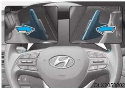
natural_image
Interior view of a car dashboard with illuminated logo and two side-view diagrams showing blue arrows pointing to the dashboard (no text or symbols on the diagram itself)The paddle shifter is available when the gear is in the D (Drive) position.
Pull the [+] or [-] paddle shifter once to shift up or down one gear and the system changes from automatic shift mode to manual shift mode.
To change back to the automatic shift mode from manual shift mode, do one of the following:
• Gently depress the accelerator pedal for more than 5 seconds.
- Drive the vehicle under 6 mph (10 km/h).
- Pull and hold the right side paddle shifter.
i Information
If the [+] and [-] paddle shifters are pulled at the same time, gear shift may not occur.
BRAKING SYSTEM
Power Brakes
Your vehicle has power-assisted brakes that adjust automatically through normal usage.
If the engine is not running or is turned off while driving, the power assist for the brakes will not work. You can still stop your vehicle by applying greater force to the brake pedal than typical. The stopping distance, however, will be longer than with power brakes.
When the engine is not running, the reserve brake power is partially depleted each time the brake pedal is applied. Do not pump the brake pedal when the power assist has been interrupted.
WARNING
Take the following precautions:
- Do not drive with your foot resting on the brake pedal. This will create abnormal high brake temperatures, excessive brake lining and pad wear, and increased stopping distances.
- When descending down a long or steep hill, use the paddle shifter and manually downshift to a lower gear in order to control your speed without using the brake pedal excessively. Applying the brakes continuously will cause the brakes to overheat and could result in a temporary loss of braking performance.
- Wet brakes may impair the vehicle's ability to safely slow down; the vehicle may also pull to one side when the brakes are applied. Applying the brakes lightly will indicate whether they have been affected in this way. Always test your brakes in this fashion after driving through deep water. To dry the brakes, lightly tap the brake pedal to heat up the brakes while maintaining a safe forward speed until brake performance returns to normal. Avoid driving at high speeds until the brakes function correctly.
Disc Brakes Wear Indicator
When your brake pads are worn and new pads are required, you will hear a high pitched warning sound from your front or rear brakes. You may hear this sound come and go or it may occur whenever you depress the brake pedal.
Note that some driving conditions or climates may cause a brake squeal when you first apply (or lightly apply) the brakes. This is normal and does not indicate a problem with your brakes.
NOTICE
To avoid costly brake repairs, do not continue to drive with worn brake pads.
i Information
Always replace brake pads as complete front or rear axle sets.
Electronic Parking Brake (EPB)
Applying the parking brake
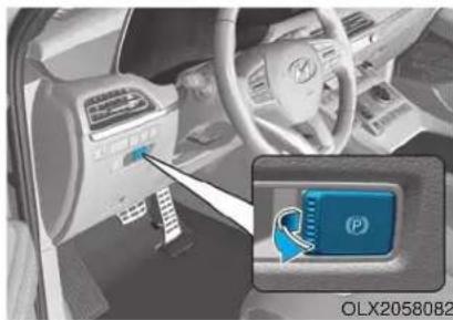
natural_image
Interior view of a car showing the dashboard and steering wheel (no visible text or symbols)To apply the EPB
(Electronic Parking Brake):
-
Depress the brake pedal.
-
Pull up the EPB switch.
Make sure the Parking Brake Warning Light comes on.
WARNING
To reduce the risk of SERIOUS INJURY or DEATH, do not operate the EPB while the vehicle is moving except in an emergency situation. It could damage the brake system and lead to an accident.
Releasing the parking brake
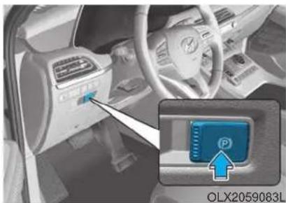
To release the EPB (Electronic Parking Brake):
- Place the ignition switch in the ON position.
• Depress and hold the brake pedal. - Press the EPB switch.
Make sure the Parking Brake Warning Light goes off.
i Information
- For your safety, you can engage the EPB even though the ignition switch is in the OFF position, but you cannot release it.
- For your safety, depress the brake pedal and release the parking brake manually with the EPB switch when you drive downhill or when backing up the vehicle.
NOTICE
- If the parking brake warning light is still on even though the EPB has been released, have the system checked by an authorized HYUNDAI dealer.
- Do not drive your vehicle with the EPB applied. It may cause excessive brake pad and brake rotor wear.
EPB (Electronic Parking Brake) may be automatically applied when:
- Requested by other systems
• The driver turns the engine off while Auto Hold is operating.
Warning messages
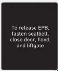
OTMA058132
To release EPB, fasten seatbelt, close door, hood and liftgate
- If you try to drive with the EPB applied, a warning will sound and a message will appear.
- If the driver's seat belt is unfastened and the engine hood or lift-gate is opened, a warning will sound and a message will appear.
- If there is a problem with the vehicle, a warning may sound and a message may appear.
If the situation occurs, depress the brake pedal and release EPB by pressing the EPB switch.
WARNING
- Whenever leaving the vehicle or parking, always come to a complete stop and continue to depress the brake pedal.
Shift the gear into the P (Park) position, press the EPB switch, and set the ignition switch to the OFF position. Take the Key with you when exiting the vehicle.
Vehicles not fully engaged in P (Park) with the parking brake set are at risk for moving inadvertently and causing injury to yourself or others.
- NEVER allow anyone who is unfamiliar with the vehicle to touch the EPB switch. If the EPB is released unintentionally, serious injury may occur.
- Only release the EPB when you are seated inside the vehicle with your foot firmly on the brake pedal.
NOTICE
- Do not apply the accelerator pedal while the parking brake is engaged. If you depress the accelerator pedal with the EPB engaged, a warning will sound and a message will appear. Damage to the parking brake may occur.
- Driving with the parking brake on can overheat the braking system and cause premature wear or damage to brake parts. Make sure the EPB is released and the Parking Brake Warning Light is off before driving.
i Information
- A clicking sound may be heard while operating or releasing the EPB. These conditions are normal and indicate that the EPB is functioning properly.
- When leaving your keys with a parking attendant or assistant, make sure to inform him/her how to operate the EPB.
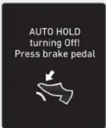
OIK057079N OIK057077N
AUTO HOLD turning Off! Press brake pedal
When the conversion from Auto Hold to EPB is not working properly a warning will sound and a message will appear.
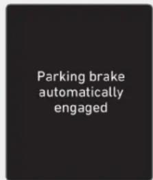
Parking brake automatically engaged
If the EPB is applied while Auto Hold is activated, a warning will sound and a message will appear.
EPB malfunction indicator

This warning light illuminates if the ignition switch is set to the ON position and goes off in approximately 3 seconds if the system is operating normally.
If the EPB malfunction indicator remains on, comes on while driving, or does not come on when the ignition switch is changed to the ON position, this indicates that the EPB may have malfunctioned.
If this occurs, have the system checked by an authorized HYUNDAI dealer.
The EPB malfunction indicator may illuminate when the ESC indicator comes on to indicate that the ESC is not working properly, but it does not indicate a malfunction of the EPB.
NOTICE
- If the EPB warning light is still on, have the system checked by an authorized HYUNDAI dealer.
- If the parking brake warning light does not illuminate or blinks even though the EPB switch was pulled up, the EPB may not be applied.
- If the parking brake warning light blinks when the EPB warning light is on, press the switch, and then pull it up. Repeat this one more time. If the EPB warning does not go off, have the system checked by an authorized HYUNDAI dealer.
Parking brake warning light
Check the Parking Brake Warning Light by placing the ignition switch to the ON position (do not start the engine).
This light will be illuminated when the parking brake is applied with the ignition switch in the START or ON position.
Before driving, be sure the parking brake is released and the Brake Warning Light is OFF.
If the Parking Brake Warning Light remains on after the parking brake is released while engine is running, there may be a malfunction in the brake system. Immediate attention is necessary.
If at all possible, cease driving the vehicle immediately. If that is not possible, use extreme caution while operating the vehicle and only continue to drive the vehicle until you can reach a safe location.
Emergency braking
If there is a problem with the brake pedal while driving, emergency braking is possible by pulling up and holding the EPB switch. Braking is possible only while you are holding the EPB switch. However, braking distance will be longer than normal.
WARNING
Do not operate the parking brake while the vehicle is moving except in an emergency situation. It could damage the brake system and lead to a severe accident.
i Information
During emergency braking, the parking brake warning light will illuminate to indicate that the system is operating.
NOTICE
If you continuously notice a noise or burning smell when the EPB is used for emergency braking, have system checked by an authorized HYUNDAI dealer.
When the EPB (Electronic Parking Brake) does not release
If the EPB does not release normally, we recommend that you contact an authorized HYUNDAI dealer by loading the vehicle on a flatbed tow truck and have the system checked.
Auto Hold
The Auto Hold maintains the vehicle in a standstill even though the brake pedal is not depressed after the driver brings the vehicle to a complete stop by depressing the brake pedal.
To apply :
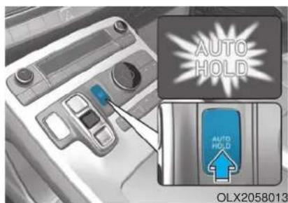
- With the driver's door and engine hood closed, depress the brake pedal and then press the [AUTO HOLD] switch. The white AUTO HOLD indicator will come on and the system will be in the standby position.
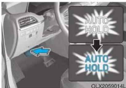
- When you stop the vehicle completely by depressing the brake pedal, the Auto Hold maintains the brake pressure to hold the vehicle stationary. The indicator changes from white to green.
- The vehicle will remain stationary even if you release the brake pedal.
- If EPB is applied, Auto Hold will be released.
To release :
- If you press the accelerator pedal with the gear in D (Drive) or Manual shift mode, the Auto Hold will be released automatically and the vehicle will start to move. The AUTO HOLD indicator changes from green to white.
- If the vehicle is restarted using the cruise control toggle switch (RES+ or SET-) while Auto Hold and cruise control is operating, the Auto Hold will be released regardless of accelerator pedal operation. The AUTO HOLD indicator changes from green to white.
WARNING
When the AUTO HOLD is automatically released by depressing the accelerator pedal, always take a look around your vehicle. Slowly depress the accelerator pedal for a smooth start.
To cancel :
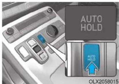
- Depress the brake pedal.
- Press the [AUTO HOLD] switch.
The AUTO HOLD indicator will turn off.
WARNING
To prevent, unexpected and sudden vehicle movement, ALWAYS press your foot on the brake pedal to cancel the Auto Hold before you:
- Drive downhill.
- Drive the vehicle in R (Reverse).
- Park the vehicle.
i Information
• The Auto Hold does not operate when:
- The driver's door is opened
- The engine hood is opened
- The gear is in P (Park) or R (Reverse)
- The EPB is applied
- For your safety, the Auto Hold automatically switches to EPB when:
- The driver's door is opened with the gear in D (Drive) or N (Neutral)
- The engine hood is opened with the gear in D (Drive) or N (Neutral)
- The vehicle stops for more than 10 minutes
- The vehicle stands on a steep slope
- The vehicle moves several times
In these cases, the parking brake warning light comes on, the AUTO HOLD indicator changes from green to white, and a warning sound and a message will appear to inform you that EPB has been automatically engaged. Before driving off again, press foot brake pedal, check the surrounding area near your vehicle and release parking brake manually with the EPB switch.
- While operating Auto Hold, you may hear mechanical noise. However, it is normal operating noise.
NOTICE
If the AUTO HOLD indicator changes to yellow, the Auto Hold is not working properly. Contact an authorized HYUNDAI dealer.
WARNING
- Depress the accelerator pedal slowly when you start the vehicle.
- For your safety, cancel the Auto Hold when you drive downhill, back up the vehicle or park the vehicle.
NOTICE
If there is a malfunction with the driver's door or engine hood open detection system, the Auto Hold may not work properly.
Contact an authorized HYUNDAI dealer.
Warning messages
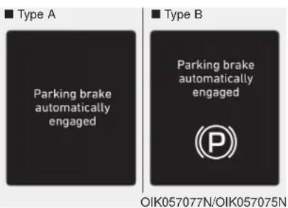
Parking brake automatically engaged
When the EPB is applied from Auto Hold, a warning will sound and a message will appear.
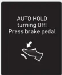
OIK057079N OIK057080L
AUTO HOLD turning Off! Press brake pedal
When the conversion from Auto Hold to EPB is not working properly a warning will sound and a message will appear.
When this message is displayed, the Auto Hold and EPB may not operate. For your safety, depress the brake pedal.
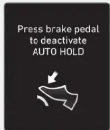
Press brake pedal to deactivate AUTO HOLD
If you did not apply the brake pedal when you release the Auto Hold by pressing the [AUTO HOLD] switch, a warning will sound and a message will appear.
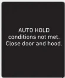
OTM058159L
AUTO HOLD conditions not met. Close door and hood.
When you press the [AUTO HOLD] switch, if the driver's door and engine hood are not closed, a warning will sound and a message will appear on the cluster LCD display.
Press the [AUTO HOLD] switch after closing the driver's door and hood.
Anti-lock Brake System (ABS)
WARNING
An Anti-Lock Braking System (ABS) or an Electronic Stability Control (ESC) system will not prevent accidents due to improper or dangerous driving maneuvers. Even though vehicle control is improved during emergency braking, always maintain a safe distance between you and objects ahead of you. Vehicle speeds should always be reduced during extreme road conditions. The braking distance for cars equipped with ABS or ESC may be longer than for those without these systems in the following road conditions.
Drive your vehicle at reduced speeds during the following conditions:
- Rough, gravel or snow-covered roads.
- On roads where the road surface is pitted or has different surface height.
- Tire chains are installed on your vehicle.
The safety features of an ABS or ESC equipped vehicle should not be tested by high speed driving or cornering. This could endanger the safety of yourself or others.
ABS is an electronic braking system that helps prevent a braking skid. ABS allows the driver to steer and brake at the same time.
Using ABS
To obtain the maximum benefit from your ABS in an emergency situation, do not attempt to modulate your brake pressure and do not try to pump your brakes. Depress your brake pedal as hard as possible.
When you apply your brakes under conditions which may lock the wheels, you may hear sounds from the brakes, or feel a corresponding sensation in the brake pedal. This is normal and it means your ABS is active.
ABS does not reduce the time or distance it takes to stop the vehicle.
Always maintain a safe distance from the vehicle in front of you.
ABS will not prevent a skid that results from sudden changes in direction, such as trying to take a corner too fast or making a sudden lane change. Always drive at a safe speed for the road and weather conditions.
ABS cannot prevent a loss of stability. Always steer moderately when braking hard. Severe or sharp steering wheel movement can still cause your vehicle to veer into oncoming traffic or off the road.
On loose or uneven road surfaces, operation of the anti-lock brake system may result in a longer stopping distance than for vehicles equipped with a conventional brake system.
The ABS warning light ( ) will stay on for several seconds after the ignition switch is in the ON position. During that time, the ABS will go through self-diagnosis and the light will go off if everything is normal. If the light stays on, you may have a problem with your ABS. Contact an authorized HYUNDAI dealer as soon as possible
WARNING
If the ABS warning light ( ) is on and stays on, you may have a problem with the ABS. Your power brakes will work normally. To reduce the risk of serious injury or death, contact your HYUNDAI dealer as soon as possible.
NOTICE
When you drive on a road having poor traction, such as an icy road, and apply your brakes continuously, the ABS will be active continuously and the ABS warning light ( ) may illuminate. Pull your car over to a safe place and turn the engine off.
Restart the engine. If the ABS warning light is off, then your ABS system is normal.
Otherwise, you may have a problem with your ABS system. Contact an authorized HYUNDAI dealer as soon as possible.
i Information
When you jump start your vehicle because of a drained battery, the ABS warning light ( ) may turn on at the same time. This happens because of the low battery voltage. It does not mean your ABS is malfunctioning. Have the battery recharged before driving the vehicle.
Electronic Stability Control (ESC)
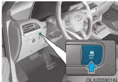
natural_image
Interior view of a car showing the dashboard and steering wheel, with a close-up inset highlighting a blue device labeled 'OLX2059016L' (no readable text or symbols beyond label)The Electronic Stability Control (ESC) system helps to stabilize the vehicle during cornering maneuvers. ESC checks where you are steering and where the vehicle is actually going. ESC applies braking pressure to any one of the vehicle's brakes and intervenes in the engine management system to assist the driver with keeping the vehicle on the intended path. It is not a substitute for safe driving practices. Always adjust your speed and driving to the road conditions.
WARNING
Never drive too fast for the road conditions or too quickly when cornering. The ESC system will not prevent accidents.
Excessive speed in turns, abrupt maneuvers, and hydroplaning on wet surfaces can result in severe accidents.
ESC operation
ESC ON condition
When the ignition switch is in the ON position, the ESC and the ESC OFF indicator lights illuminate for approximately three seconds. After both lights go off, the ESC is enabled.
When operating

When the ESC is in operation, the ESC indicator light blinks:
- When you apply your brakes under conditions which may lock the wheels, you may hear sounds from the brakes, or feel a corresponding sensation in the brake pedal. This is normal and it means your ESC is active.
- When the ESC activates, the engine may not respond to the accelerator as it does under routine conditions.
- If the Cruise Control was in use when the ESC activates, the Cruise Control automatically disengages. The Cruise Control can be reengaged when the road conditions allow. See "Cruise Control System" later in this chapter. (if equipped)
- When moving out of the mud or driving on a slippery road, the engine RPM (revolutions per minute) may not increase even if you press the accelerator pedal deeply. This is to maintain the stability and traction of the vehicle and does not indicate a problem.
ESC OFF condition
To cancel ESC operation :
• State 1
Press the ESC OFF button briefly. The ESC OFF indicator light and message "Traction Control disabled" will illuminate. In this state, the traction control function of ESC (engine management) is disabled, but the brake control function of ESC (braking management) still operates.
• State 2
Press and hold the ESC OFF button continuously for more than 3 seconds. The ESC OFF indicator light and message "Traction and Stability Control disabled" illuminates and a warning chime sounds. In this state, both the traction control function of ESC (engine management) and the brake control function of ESC (braking management) are disabled. If the ignition switch is placed to the LOCK/OFF position when ESC is off, ESC remains off. Upon restarting the engine, the ESC will automatically turn on again.
Indicator lights
■ ESC indicator light (blinks)

■ ESC OFF indicator light (comes on)

When the ignition switch is placed to the ON position, the ESC indicator light illuminates, then goes off if the ESC system is operating normally.
The ESC indicator light blinks whenever the ESC is operating.
If ESC indicator light stays on, your vehicle may have a malfunction with the ESC system. When this warning light illuminates have your vehicle checked by an authorized HYUNDAI dealer as soon as possible.
The ESC OFF indicator light comes on when the ESC is turned off.
WARNING
When the ESC is blinking, this indicates the ESC is active:
Drive slowly and NEVER attempt to accelerate. NEVER turn the ESC off while the ESC indicator light is blinking or you may lose control of the vehicle resulting in an accident.
NOTICE
Driving with wheels and tires with different sizes may cause the ESC system to malfunction. Before replacing tires, make sure all four tires and wheels are the same size. Never drive the vehicle with different sized wheels and tires installed.
ESC OFF usage
When Driving
The ESC OFF mode should only be used briefly to help free the vehicle if stuck in snow or mud by temporarily stopping operation of the ESC to maintain wheel torque.
To turn ESC off while driving, press the ESC OFF button while driving on a flat road surface.
NOTICE
To prevent damage to the transmission:
- Do not allow wheel(s) of one axle to spin excessively while the ESC, ABS, and parking brake warning lights are displayed. The repairs would not be covered by the vehicle warranty. Reduce engine power and do not spin the wheel(s) excessively while these lights are displayed.
- When operating the vehicle on a dynamometer, make sure the ESC is turned off (ESC OFF light illuminated).
i Information
Turning the ESC off does not affect ABS or standard brake system operation.
Vehicle Stability Management (VSM)
The Vehicle Stability Management (VSM) is a function of the Electronic Stability Control (ESC) system. It helps ensure the vehicle stays stable when accelerating or braking suddenly on wet, slippery and rough roads where traction over the four tires can suddenly become uneven.
WARNING
Take the following precautions when using the Vehicle Stability Management (VSM):
- ALWAYS check the speed and the distance to the vehicle ahead. The VSM is not a substitute for safe driving practices.
- Never drive too fast for the road conditions. The VSM system will not prevent accidents. Excessive speed in bad weather, slippery and uneven roads can result in severe accidents.
VSM operation
VSM ON condition
The VSM operates when:
- The Electronic Stability Control (ESC) is on.
- Vehicle speed is approximately above 13 mph (22 km/h) on curve roads.
- Vehicle speed is approximately above 6 mph (10 km/h) when the vehicle is braking on a two surface road.
* The two surface road is made of surfaces which have different friction forces.
When operating
When you apply your brakes under conditions which may activate the ESC, you may hear sounds from the brakes, or feel a corresponding sensation in the brake pedal. This is normal and it means your VSM is active.
i Information
The VSM does not operate when:
- Driving on a banked road such as gradient or incline.
- Driving rearward.
- ESC OFF indicator light is on.
- EPS (Electric Power Steering) warning light (☑) is on or blinks.
Driving with wheels and tires with different sizes may cause the ESC system to malfunction. Before replacing tires, make sure all four tires and wheels are the same size. Never drive the vehicle with different sized tires and wheels installed.
WARNING
If ESC indicator light ( ) or EPS warning light ( ) stays on or blinks, your vehicle may have a malfunction with the VSM system. When the warning light illuminates, have your vehicle checked by an authorized HYUNDAI dealer as soon as possible.
Hill-Start Assist Control (HAC)
The Hill-Start Assist Control (HAC) helps prevent the vehicle from rolling backwards when starting a vehicle from a stop on a hill. The system operates the brakes automatically for approximately 2 seconds and releases the brake after 2 seconds or when the accelerator pedal is depressed.
WARNING
Always be ready to depress the accelerator pedal when starting off on an incline. The HAC activates only for approximately 2 seconds.
NOTICE
• The HAC does not operate when the vehicle is shifted to P (Park) or N (Neutral)
- The HAC activates even though the ESC (Electronic Stability Control) is off but does not activate when the ESC has malfunctioned.
Downhill Brake Control (DBC) (if equipped)
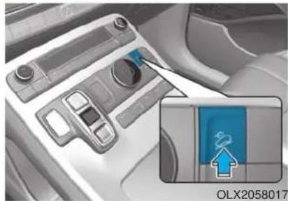
natural_image
Interior view of a car dashboard with a highlighted control panel and an inset showing a blue upward arrow (no text or symbols)The Downhill Brake Control (DBC) feature assists the driver to descend down a steep hill without having to depress the brake pedal.
The system automatically applies the brakes to maintain the vehicle speed below a certain speed and allows the driver to concentrate on steering the vehicle down hill.
The DBC defaults to the off position whenever the ignition switch is placed to the ON position. Press the button to activate the system and press the button again to deactivate.
DBC operation
| Mode Indicator light Description | ||
| Standby |  Green light turns on Green light turns on | Press the DBC button when the vehicle speed is under 37 mph (60 km/h). The DBC system will turn on and enter the standby mode.The system does not turn on if the vehicle speed is over 37 mph (60 km/h). |
| Activated |  Green light blinks Green light blinks | In the standby mode, the DBC will activate under the following conditions:The hill is steep enough.The accelerator pedal is not depressed.The vehicle speed is within 2~25 mph (4~40 km/h) range (within 1.5~5 mph (2.5~8 km/h) when reversing).Within the activation speed range 2~25 mph (4~40 km/h), the driver can control the vehicle speed by depressing the brake/accelerator pedal. |
| Deactivated | Green light turns off | The DBC will turn off under the following conditions:The DBC button is pressed again.The vehicle speed is over 37 mph (60 km/h). |
 Green light turns on (maintains standby mode) Green light turns on (maintains standby mode) | The DBC will be deactivated but maintain the standby mode under the following conditions:The hill is not steep enough.The vehicle speed is between 25~37 mph (40~60 km/h). | |
| System malfunction |  Yellow light turns on Yellow light turns on | The yellow warning light illuminates when the system may have malfunctioned or may not work properly during the activation. In this case, the DBC system is deactivated. Have the system checked by an authorized HYUNDAI dealer as soon as possible. |
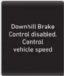
OTMA048167
Downhill Brake Control disabled. Control vehicle speed
When the DBC system is not working properly this warning message will appear on the LCD display and you will hear a warning sound. If this occurs, control the vehicle speed by depressing the brake pedal.
WARNING
Always turn off the DBC on normal roads. The DBC might activate inadvertently from the standby mode when driving through speed bumps or making sharp curves.
i Information
- Noise or vibration may occur from the brakes when the DBC is activated.
• The rear stop light comes on when DBC is activated.
NOTICE
• The DBC may not deactivate on steep inclines even though the brake or accelerator pedal is depressed.
- The DBC system may not always maintain the vehicle speed at a certain speed.
• The DBC does not operate when:
- The gear is in P (Park).
- The ESC is activated.
Trailer Stability Assist (TSA)
Trailer Stability Assist system helps stabilize the vehicle and trailer when the trailer sways or oscillates. There are various reasons making the vehicle sway and oscillate.
Factors of swaying are such as:
- High speed
- Strong crosswinds
- Improper overloading
- Sudden controlling of steering wheel
- Uneven road
Trailer Stability Assist system continuously analyzes the vehicle and trailer instability. When the Trailer Stability Assist system detects some sway, the brakes are applied automatically to stabilize the vehicle on the front wheel. However, if it is not enough to stabilize, the brakes are applied on all wheels automatically and engine power is properly reduced. When the vehicle is stable from swaying, trailer stability assist system does not operate.
Good Braking Practices
WARNING
Whenever leaving the vehicle or parking, always come to a complete stop and continue to depress the brake pedal. Shift the gear to P (Park), then apply the parking brake, and place the ignition switch in the LOCK/OFF position.
Vehicles parked with the parking brake not applied or not fully engaged may roll inadvertently and may cause injury to the driver and others. ALWAYS apply the parking brake before exiting the vehicle.
Wet brakes can be dangerous! The brakes may get wet if the vehicle is driven through standing water or if it is washed. Your vehicle will not stop as quickly if the brakes are wet. Wet brakes may cause the vehicle to pull to one side.
To dry the brakes, apply the brakes lightly until the braking action returns to normal, taking care to keep the vehicle under control at all times. If the braking action does not return to normal, stop as soon as it is safe to do so and call an authorized HYUNDAI dealer for assistance.
DO NOT drive with your foot resting on the brake pedal. Even light, but constant pedal pressure can result in the brakes overheating, brake wear, and possibly even brake failure.
If a tire goes flat while you are driving, apply the brakes gently and keep the vehicle pointed straight ahead while you slow down. When you are moving slowly enough for it to be safe to do so, pull off the road and stop in a safe location.
Keep your foot firmly on the brake pedal when the vehicle is stopped to prevent the vehicle from rolling forward.
ALL WHEEL DRIVE (AWD) (IF EQUIPPED)
The All Wheel Drive (AWD) system delivers engine torque to both the front and rear wheels for extra traction. AWD is useful when maximum traction is required on slippery, muddy, wet, or snow-covered roads.
Occasional off-road use such as established unpaved roads and trails are OK. It is always important that the driver carefully reduces the speed to a level that does not exceed the safe operating speed for those conditions.
WARNING
To reduce the risk of SERIOUS INJURY or DEATH:
- Do not drive in conditions that exceed the vehicles intended design such as challenging off-road conditions.
- Avoid high speeds when cornering or turning.
- Do not make quick steering wheel movements, such as sharp lane changes or fast, sharp turns.
- The risk of a rollover is greatly increased if you lose control of your vehicle at highway speeds.
- Loss of control often occurs if two or more wheels drop off the roadway and the driver over steers to reenter the roadway.
- In the event your vehicle leaves the roadway, do not steer sharply. Instead, slow down before pulling back into the travel lanes.
NOTICE
- Do not drive in water if the level is higher than the bottom of the vehicle.
- Check your brake condition once you are out of mud or water. Depress the brake pedal several times as you move slowly until you feel normal braking return.
- Shorten your scheduled maintenance interval if you drive in off-road conditions such as sand, mud or water (see "Maintenance Under Severe Usage Conditions" in chapter 7).
• Always wash your vehicle thoroughly after off road use, especially the bottom of the vehicle. - Be sure to equip the vehicle with four tires of the same size and type.
- Make sure that a full time AWD vehicle is towed by a flat bed tow truck.
AWD Operation
All Wheel Drive (AWD) mode selection
| Transfer mode Selection mode Description | ||
| AWD AUTO(Normal driving) | - | In the AWD AUTO mode, under normal operating conditions, the vehicle operates similar to conventional 2WD vehicles. If the system determines there is a need for four wheel drive, the engine's driving power is distributed to all four wheels automatically. Use this mode when driving on normal roads.If you select the "Driving force distribution" in the cluster, Driving force distribution (AWD) state is displayed. |
| SNOW | 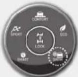 | In this mode, the vehicle can start stably by properly distributing the driving force of the vehicle on slippery roads such as snowy roads. And you can drive safely by suppressing wheel slip. |
| AWD LOCK | 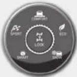 | The main goal of AWD Lock mode is toallow a driver to maximize the vehicle's traction under extreme driving conditions such as unpaved off-road, sandy roads, and muddy roads.AWD Lock mode is in operation only when a vehicle travels at 25 mph (40 km/h) or less. When travelling at 25 mph (40 km/h) or faster, the mode will switch to AWD Auto. When travelling at 20 mph (30 km/h) or less, the mode will switch back to AWD Lock.Press the AWD Lock mode switch again to switch back to AWD Auto. |
When the AWD LOCK mode is deactivated, a shock may be felt as the drive power is delivered entirely to the front wheels. This shock is not a mechanical failure.
For safe AWD operation
Before driving
- Make sure all passengers are wearing seat belts.
- Sit upright and closer to the steering wheel than usual. Adjust the steering wheel to a position comfortable for you to drive.
Driving on snow-covered or icy roads
- Start off slowly by applying the accelerator pedal gently.
- Use snow tires or tire chains.
- Keep sufficient distance between your vehicle and the vehicle in front of you.
- Apply engine braking during deceleration by using the paddle shifter and manually selecting a lower gear.
- Avoid speeding, rapid acceleration, sudden brake applications, and sharp turns to prevent skids.
Driving in sand or mud
- Maintain slow and constant speed.
- Use tire chains driving in mud if necessary.
- Keep sufficient distance between your vehicle and the vehicle in front of you.
- Reduce vehicle speed and always check the road condition.
- Avoid speeding, rapid acceleration, sudden brake applications, and sharp turns to prevent getting stuck.
CAUTION
When the vehicle is stuck in snow, sand or mud, place a non-slip material under the drive wheels to provide traction OR Slowly spin the wheels in forward and reverse directions which causes a rocking motion that may free the vehicle. However, avoid running the engine continuously at high rpm, doing so may damage the AWD system.
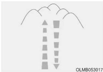
natural_image
Diagram showing two vertical bars with arrows pointing upward and downward, above a cloud-like shape (no text or symbols)Driving up or down hills
- Driving uphill
- Before starting off, check if it is possible to drive uphill.
- Drive as straight as possible.
- Driving downhill
- Do not change gear while driving downhill. Select gear before driving downhill.
- Drive slowly using engine braking while driving downhill.
- Drive straight as possible.
WARNING
Exercise extreme caution when driving up or down steep hills. The vehicle may flip over depending on the grade, the terrain, and the trail conditions.
WARNING
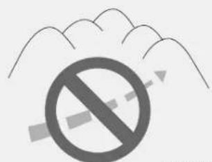
OLMB053018
Do not drive across the contour of steep hills. A slight change in the wheel angle can destabilize the vehicle, or a stable vehicle may lose stability if the vehicle stops its forward motion. Your vehicle may roll over and lead to a serious injury or death.
Driving through water
- Try to avoid driving in deep standing water. It may stall your engine and clog your exhaust system.
- If you need to drive in water, stop your vehicle, set the vehicle in AWD LOCK mode and drive under 5 mph (8 km/h).
- Do not change gear while driving in water.
CAUTION
Always drive slowly in water. If you drive too fast, water may get into the engine compartment and wet the ignition system causing your vehicle to suddenly stop.
Additional driving conditions
- Become familiar with the off-road conditions before driving.
• Always pay attention when driving off-road and avoid dangerous areas. - Drive slowly when driving in heavy wind.
- Reduce vehicle speed when cornering. The center of gravity of AWD vehicles is higher than conventional 2WD vehicles, making them more likely to roll over when you rapidly turn corners.
• Always hold the steering wheel firmly when you are driving off-road.
WARNING
Do not grab the inside of the steering wheel when you are driving off-road. You may hurt your arm by a sudden steering maneuver or from steering wheel rebound due to an impact with objects on the ground. You could lose control of the steering wheel which may lead to serious injury or death.
LCD display message
Transmission hot! Park with engine On
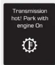
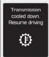
OJS058137L/OJS058138L
• Under certain conditions, such as repeated stop-and-go launches on steep grades, sudden take off or acceleration, or other harsh driving conditions (mud or sand road), the transmission temperatures will increase excessively. Finally the transmission could be overheated.
- If the vehicle continues to be driven and the automatic transmission temperatures reach the maximum temperature limit, the "Transmission hot! Park with engine On" warning will be displayed. When this occurs the automatic transmission is disabled until the automatic transmission cools to normal temperatures.
- The warning will display a time to wait for the transmission to cool.
- If this occurs, pull over to a safe location, stop the vehicle with the engine running, apply the brakes and shift the vehicle to P (Park), and allow the transmission to cool.
- When the message "Transmission cooled down. Resume driving" appears you can continue to drive your vehicle.
- When possible, drive the vehicle smoothly.
Emergency Precautions
Tires
Do not use a tire and wheel package with a different size and type from the one originally installed on your vehicle. It can affect the safety and performance of your vehicle, which could lead to steering failure or rollover causing serious injury.
When replacing the tires, be sure to equip all four tires with the tire and wheel of the same size, type, tread, brand and load-carrying capacity. If you equip your vehicle with any tire/wheel combination not recommended by HYUNDAI for off-road driving, you should not use these tires for highway driving.
WARNING
Never start or run the engine while a full-time AWD vehicle is raised on a jack. The vehicle can slip or roll off of a jack causing serious injury or death to you or those nearby.
Towing
AWD vehicles must be towed with a wheel lift and dollies or flatbed equipment with all the wheels off the ground. For more details, refer to "Towing" in chapter 6.
Dynamometer testing
A full-time AWD vehicle must be tested on a special four wheel chassis dynamometer.
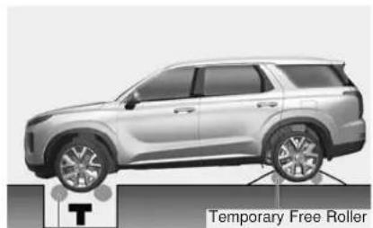
natural_image
Side profile illustration of a silver SUV with visible suspension and wheels, labeled 'Temporary Free Roller' (no other text or symbols)Roll Tester (Speedometer)
Temporary Free Roller
OLX2058010
A full-time AWD vehicle should not be tested on a 2WD roll tester. If a 2WD roll tester must be used, perform the following procedure:
- Check the tire pressures recommended for your vehicle.
- Place the front wheels on the roll tester for a speedometer test as shown in the illustration.
- Release the parking brake.
- Place the rear wheels on the temporary free roller as shown in the illustration.
CAUTION
- Never engage the parking brake while performing the test.
- When the vehicle is lifted up, do not operate the front and rear wheel separately. All four wheels should be operated.
WARNING
Keep away from the front of the vehicle while the vehicle is in gear on the dynamometer. The vehicle can jump forward and cause serious injury or death.
ISG (IDLE STOP AND GO) SYSTEM (IF EQUIPPED)
The Idle Stop and Go (ISG) system automatically and temporarily shuts down the engine when the vehicle is stopped and idling to improve fuel efficiency and reduce exhaust gas emissions. (i.e. red stop light, stop sign, and traffic jam).
The engine is automatically started upon satisfying the starting conditions.
The ISG system is always active, when the engine is running.
i Information
When the engine is automatically started by the ISG system, some warning lights (i.e. ABS, ESC, ESC OFF, EPS, and parking brake warning light) may illuminate for a few seconds due to the low battery voltage. However, it does not indicate a malfunction with the ISG system.
To Activate the ISG System
Prerequisite for activation
The ISG system operates in the following situations.
- The driver's seatbelt is fastened.
- The driver's door and the hood are closed.
- The brake vacuum pressure is adequate.
- The battery is sufficiently charged.
- The outside temperature is between 14 °F and 95 °F (-10 °C and 35 °C).
- The engine coolant temperature is not too low.
- The system is not in the diagnostic mode.
- The incline is gradual.
- Steering wheel is turned less than 180 degrees
- Shift lever is in DRIVE or NEU-TRAL
i Information
•

The ISG system is not activated, when the prerequisites to activate the ISG system are unsatisfied. In this case, the ISG
OFF button indicator illuminates, and the auto stop indicator ( ) illuminates in yellow on the instrument cluster.
- When the above indicator remains illuminated on the instrument cluster, we recommend that you have the IGS system checked by an authorized HYUNDAI dealer.
Auto stop
To stop the engine in idle stop mode
- Decrease the vehicle speed to 0 mph.
- Depress the brake pedal with the shift lever in D (Drive) or N (Neutral).
The auto stop indicator (Alluminates in green on the instrument cluster, when the engine stops.
i Information
The driving speed must reach at least 3 mph (5 km/h) after an idle stop to stop the engine in idle stop mode again.
In auto stop mode, when the driver opens the hood, the ISG system will be deactivated.
When the system is deactivated:
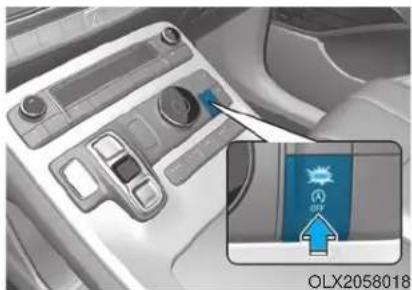
natural_image
Interior view of a car dashboard with a highlighted control panel and an inset showing a blue 'AIR' button (no text or symbols on the main components)The ISG OFF button indicator illuminates.
OIK057173N
If the message "Auto Stop is Off.
Start vehicle manually", appears on the LCD display with a beep sound, restart the vehicle manually by depressing the brake pedal with the vehicle shifted to P (Park) or N (Neutral). For your safety, restart the vehicle in the P (Park) position.
Auto start
To restart the engine in the auto stop mode
Release the brake pedal.
- When Auto Hold is activated, if you release the brake pedal, the engine will be in the auto stop state. However, if you depress the accelerator pedal, the engine will start again.
The auto stop indicator (A) goes OFF on the instrument cluster, when the engine is restarted.
The engine is automatically restarted in the following situations.
- The fans speed of the manual climate control system is set above the 3rd position, with the air condition ON.
- The fan speed of the automatic climate control system is set above the 6th position, with the air condition ON.
- A certain period of time has elapsed with the air condition ON.
• The defroster is activated.
• The brake vacuum pressure is low. - The battery is weak.
- The vehicle is shifted to P (Park) or R (Reverse) when the brake pedal is depressed or the Auto Hold is activated.
- The door is opened or seat belt is unfastened when the brake pedal is depressed or Auto Hold is activated.
- The EPB is pressed when the Auto Hold is activated.
The auto stop indicator (A) links in green for 5 seconds on the instrument cluster.
OIK057086N
The auto start is temporarily deactivated in the following situations.
When the gear is shifted from N (Neutral) to R (Reverse), D (Drive) or Manual shift mode without the brake pedal depressed. A message "Press brake pedal for Auto Start" will appear on the LCD display. To activate auto start, depress the brake pedal.
To Deactivate the ISG System
- Press the ISG OFF button to deactivate the ISG system. Then, the ISG OFF button indicator illuminates.
- Press the ISG OFF button again to reactivate the ISG system. Then, the ISG OFF button indicator turns OFF.
ISG System Malfunction
The ISG system may not operate: When there is a malfunction with the ISG sensors or the ISG system.
The followings occur, when there is a malfunction with the ISG system:
- The auto stop indicator (A) will blink in yellow on the instrument cluster.
- The light on the ISG OFF button will illuminate.
i Information
- When you cannot turn OFF the ISG OFF button indicator by pressing the ISG OFF button, or when the malfunction with the ISG system persists, contact an authorized HYUNDAI dealer.
- You can turn off the ISG OFF button indicator by driving over 50 mph (80 km/h) for up to 2 hours with the fan speed below the 2nd position. If the ISG OFF button indicator remains ON, contact an authorized HYUNDAI dealer.
WARNING
When the engine is in auto stop mode, the engine may restart. Before leaving the vehicle or checking the engine compartment, stop the engine placing the ignition switch to the LOCK/OFF position or remove the ignition key.
Battery Sensor Deactivation
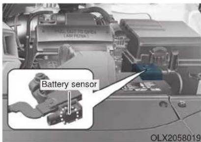
The battery sensor is deactivated, when the battery is disconnected from the negative pole for maintenance purpose.
In this case, the ISG system is limitedly operated due to the battery sensor deactivation. Thus, the driver needs to take the following procedures to reactivate the battery sensor after disconnecting the battery.
Prerequisites to reactivate the battery sensor
Switch "ON" and "OFF" the ignition one time. Park the vehicle for a minimum of 4 hours with the hood and all doors closed.
Pay extreme caution not to connect any accessories (i.e. navigation and black box) to the vehicle with the engine in the OFF status. If not, the battery sensor may not be reactivated.
i Information
The ISG system may not operate in the following situations.
- There is a malfunction with the ISG system.
- The battery is weak.
- The brake vacuum pressure is low. If this occurs, have the ISG system checked by an authorized HYUNDAI dealer.
NOTICE
- Use only a genuine HYUNDAI Absorbent Glass Mat (AGM) battery for replacement. If not, the ISG system may not operate normally.
- Do not recharge the Absorbent Glass Mat (AGM) battery with a general battery charger. It may damage or explode the Absorbent Glass Mat (AGM) battery.
- Do not remove the battery cap. The battery electrolyte, which is harmful to the human body, may leak out.
DRIVE MODE INTEGRATED CONTROL SYSTEM (2WD)
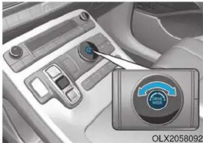
natural_image
Interior view of a car dashboard with a highlighted circular dial indicator (no text or symbols on the dial itself)The drive mode may be selected according to the driver's preference or road condition.
Drive Mode
The mode changes whenever the DRIVE MODE selection knob is rotated.
- SMART mode :
SMART mode automatically adjusts the driving mode (ECO ↔ COMFORT ↔ SPORT) in accordance with the driver's driving habits.
- SPORT mode :
SPORT mode provides sporty but firm riding.
- ECO mode :
ECO mode helps improve fuel efficiency for eco-friendly driving.
- COMFORT mode :
COMFORT mode provides smooth driving and comfortable riding.
SMART mode
SMART
SMART mode selects the proper driving mode among ECO, COMFORT, and SPORT by judging
the driver's driving habits (i.e. Economical or Aggressive) from the brake pedal depression or the steering wheel operation.
- Rotate the DRIVE MODE selection knob to activate SMART mode. When SMART mode is activated, the indicator illuminates on the instrument cluster.
• The vehicle starts in SMART mode, when the engine was turned OFF in SMART mode.
• SMART mode automatically controls gear shifting patterns, engine torque, in accordance with the driver's driving habits.
i Information
- When you mildly drive the vehicle in SMART mode, the driving mode changes to ECO mode to improve fuel efficiency. However, the actual fuel efficiency may differ in accordance with your driving situations (i.e. upward/downward slope, vehicle deceleration/acceleration).
- When you dynamically drive the vehicle in SMART mode by abruptly decelerating or sharply turning the driving mode changes to SPORT mode. However, it may adversely affect fuel economy.
Various driving situations, which you may encounter in SMART mode
- The driving mode automatically changes to ECO mode after a certain period of time, when you gently depress the accelerator pedal (Your driving is categorized to be economical.).
- The driving mode automatically changes from SMART ECO mode to SMART COMFORT mode after a certain period of time, when you sharply or repetitively depress the accelerator pedal.
-
The driving mode automatically changes to SMART COMFORT mode with the same driving patterns, when the vehicle starts to drive on an upward slope of a certain angle. The driving mode automatically returns to SMART ECO mode, when the vehicle enters a leveled road.
-
The driving mode automatically changes to SMART SPORT, when you abruptly accelerate the vehicle or repetitively operate the steering wheel (Your driving is categorized to be aggressive.). In this mode, your vehicle drives in a lower gear for abrupt accelerating/decelerating and increases the engine brake performance.
- You may still sense the engine braking performance, even when you release the accelerator pedal in SMART SPORT mode. It is because your vehicle remains in lower gear over a certain period of time for next acceleration. Thus, it is a normal driving situation, not indicating any malfunction.
- The driving mode automatically changes to SMART SPORT mode only in harsh driving situations. In most of the normal driving situations, the driving mode sets to be either in SMART ECO mode or in SMART COMFORT mode.
Limitation of SMART mode
The SMART mode may be limited in following situations. (The OFF indicator illuminates in those situations.)
- The driver uses the paddle shifter (manual shift mode) :
It deactivates SMART mode. The vehicle drives, as the driver manually changes gear with the paddle shifter.
• The cruise control is activated :
The cruise control system may deactivate the SMART mode when the vehicle is controlled by the set speed of the smart cruise control system. (SMART mode is not deactivated just by activating the cruise control system.)
- The transmission oil temperature is either extremely low or extremely high :
The SMART mode can be active in most of the normal driving situations. However, an extremely high/low transmission oil temperature may temporarily deactivate the SMART mode, because the transmission condition is out of normal operation condition.
SPORT
SPORT
SPORT mode manages the driving dynamics by automatically adjusting the steering effort, and
the engine and transmission control logic for enhanced driver performance.
- When SPORT mode is selected by rotating the DRIVE MODE selection knob, the SPORT indicator will illuminate.
- Whenever the engine is restarted, the drive mode will revert back to COMFORT mode. If SPORT mode is desired, re-select SPORT mode.
- When SPORT mode is activated:
- The engine rpm will tend to remain a little higher for a brief time even after releasing the accelerator. This is typical when the SPORT mode is activated.
- Upshifts are delayed when accelerating
i Information
In SPORT mode, the fuel efficiency may decrease.
ECO mode
ECO
When the drive mode is set to ECO mode, the engine and transmission control logic are changed to maximize fuel efficiency.
- When ECO mode is selected by rotating the DRIVE MODE selection knob, the ECO indicator will illuminate.
- The vehicle starts in ECO mode, when the engine was turned OFF in ECO mode.
i Information
Fuel efficiency depends on the driver's driving habit and road condition.
When ECO mode is activated:
- The acceleration response may be slightly reduced if the accelerator pedal is depressed moderately.
- The air conditioner performance may be limited.
- The shift pattern of the automatic transmission may change.
- The engine noise may be louder at some automatic transmission shifts as down-shift requires pressing down more on the accelerator.
The above situations are normal conditions when ECO mode is activated to help improve fuel efficiency.
Limitation of ECO mode operation: If the following conditions occur while ECO mode is operating, the system operation is limited even though there is no change in the ECO indicator.
- When the coolant temperature is low:
The system will be limited until engine performance becomes normal. - When driving up a hill:
The system will be limited to gain power when driving uphill because engine torque is restricted. - When driving the vehicle in manual shift mode using the paddle shifter.
The system will be limited according to the shift location.
DRIVE MODE INTEGRATED CONTROL SYSTEM (AWD)
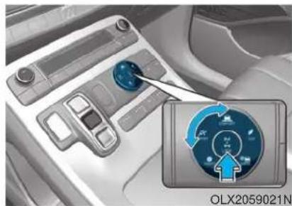
natural_image
Interior view of a car dashboard with a digital display showing a speedometer (no text or symbols on the device itself)The drive mode may be selected according to the driver's preference or road condition.
Drive Mode
The mode changes whenever the DRIVE MODE selection knob is rotated.
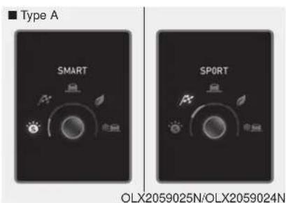
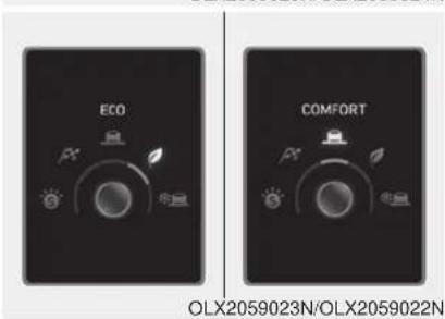
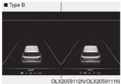
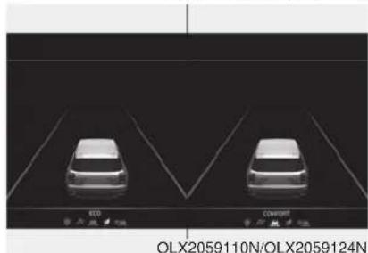
natural_image
Two cars displayed in a parking lot with lane markings, no visible text or symbols on the cars or background.-
SMART mode : SMART mode automatically adjusts the driving mode (ECO ↔ COMFORT ↔SPORT) in accordance with the driver's driving habits.
-
SPORT mode :
SPORT mode provides sporty but firm riding. - ECO mode :
ECO mode helps improve fuel efficiency for eco-friendly driving. - COMFORT mode :
COMFORT mode provides smooth driving and comfortable riding.
SMART mode
SMART
SMART mode selects the proper driving mode among ECO, COMFORT, and SPORT by judging the driver's driving habits (i.e. Economical or Aggressive) from the brake pedal depression or the steering wheel operation.
- Rotate the DRIVE/TERRAIN mode selection knob to activate SMART mode. When SMART mode is activated, the indicator illuminates on the instrument cluster.
- The vehicle starts in SMART mode, when the engine was turned OFF in SMART mode.
- SMART mode automatically controls gear shifting patterns, engine torque, in accordance with the driver's driving habits.
- SMART mode automatically controls the vehicle driving, such as gear shifting patterns, engine torque, riding quality (if equipped with the electronic suspension system), and power distribution (if equipped with the All-Wheel Drive (AWD) system), in accordance with the driver's driving habits.
i Information
- When you mildly drive the vehicle in SMART mode, the driving mode changes to ECO mode to improve fuel efficiency. However, the actual fuel efficiency may differ in accordance with your driving situations (i.e. upward/downward slope, vehicle deceleration/acceleration).
- When you dynamically drive the vehicle in SMART mode by abruptly decelerating or sharply turning the driving mode changes to SPORT mode. However, it may adversely affect fuel economy.
Various driving situations, which you may encounter in SMART mode
- The driving mode automatically changes to ECO mode after a certain period of time, when you gently depress the accelerator pedal (Your driving is categorized to be economical.).
- The driving mode automatically changes from SMART ECO mode to SMART COMFORT mode after a certain period of time, when you sharply or repetitively depress the accelerator pedal.
-
The driving mode automatically changes to SMART COMFORT mode with the same driving patterns, when the vehicle starts to drive on an upward slope of a certain angle. The driving mode automatically returns to SMART ECO mode, when the vehicle enters a leveled road.
-
The driving mode automatically changes to SMART SPORT, when you abruptly accelerate the vehicle or repetitively operate the steering wheel (Your driving is categorized to be aggressive.). In this mode, your vehicle drives in a lower gear for abrupt accelerating/decelerating and increases the engine brake performance.
- You may still sense the engine braking performance, even when you release the accelerator pedal in SMART SPORT mode. It is because your vehicle remains in lower gear over a certain period of time for next acceleration. Thus, it is a normal driving situation, not indicating any malfunction.
- The driving mode automatically changes to SMART SPORT mode only in harsh driving situations. In most of the normal driving situations, the driving mode sets to be either in SMART ECO mode or in SMART COMFORT mode.
Limitation of SMART mode
The SMART mode may be limited in following situations. (The OFF indicator illuminates in those situations.)
- The driver uses the paddle shifter (manual shift mode) :
It deactivates SMART mode. The vehicle drives, as the driver manually changes gear with the paddle shifter.
• The cruise control is activated :
The cruise control system may deactivate the SMART mode when the vehicle is controlled by the set speed of the smart cruise control system. (SMART mode is not deactivated just by activating the cruise control system.)
- The transmission oil temperature is either extremely low or extremely high :
The SMART mode can be active in most of the normal driving situations. However, an extremely high/low transmission oil temperature may temporarily deactivate the SMART mode, because the transmission condition is out of normal operation condition.
SPORT
SPORT
SPORT mode manages the driving dynamics by automatically adjusting the steering effort, and
the engine and transmission control logic for enhanced driver performance.
- When SPORT mode is selected by rotating the DRIVE/TERRAIN mode selection knob, the SPORT indicator will illuminate.
- Whenever the engine is restarted, the drive mode will revert back to COMFORT mode. If SPORT mode is desired, re-select SPORT mode.
- When SPORT mode is activated:
- The engine rpm will tend to remain a little higher for a brief time even after releasing the accelerator. This is typical when the SPORT mode is activated.
- Upshifts are delayed when accelerating
i Information
In SPORT mode, the fuel efficiency may decrease.
ECO mode
ECO
When the drive mode is set to ECO mode, the engine and transmission control logic are changed to maximize fuel efficiency.
- When ECO mode is selected by rotating the DRIVE mode selection knob, the ECO indicator will illuminate.
- The vehicle starts in ECO mode, when the engine was turned OFF in ECO mode.
i Information
Fuel efficiency depends on the driver's driving habit and road condition.
When ECO mode is activated:
- The acceleration response may be slightly reduced if the accelerator pedal is depressed moderately.
- The air conditioner performance may be limited.
- The shift pattern of the automatic transmission may change.
- The engine noise may be louder at some automatic transmission shifts as down-shift requires pressing down more on the accelerator.
The above situations are normal conditions when ECO mode is activated to help improve fuel efficiency.
Limitation of ECO mode operation: If the following conditions occur while ECO mode is operating, the system operation is limited even though there is no change in the ECO indicator.
- When the coolant temperature is low:
The system will be limited until engine performance becomes normal. - When driving up a hill:
The system will be limited to gain power when driving uphill because engine torque is restricted. - When driving the vehicle in manual shift mode using the paddle shifter. The system will be limited according to the shift location.
FORWARD COLLISION-AVOIDANCE ASSIST (FCA) SYSTEM
The Forward Collision-Avoidance Assist (FCA) system is designed to help detect and monitor the vehicle ahead or help detect a pedestrian in the roadway through radar signals and camera recognition to warn the driver that a collision is imminent, and if necessary, apply emergency braking.
WARNING
Take the following precautions when using the Forward Collision-Avoidance Assist (FCA) system:
- This system is only a supplemental system and it is not intended to, nor does it replace the need for extreme care and attention of the driver. The sensing range and objects detectable by the sensors are limited. Pay attention to the road conditions at all times.
- Drive at posted speed limits and accordance to road conditions.
- Always drive cautiously to prevent unexpected and sudden situations from occurring. The Forward Collision-Avoidance system may not always stop the vehicle completely and is only intended to help mitigate a collision that is imminent.
System Setting and Operation
System setting
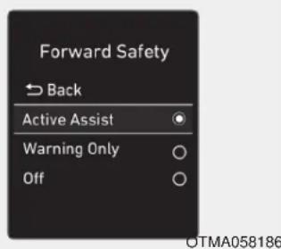
- Setting Forward Safety function
The driver can activate the FCA by placing the ignition switch to the ON position and by selecting:
'User Settings →Driver Assistance →Forward Safety'
- If you select "Active Assist", the FCA system activates. The FCA produces warning messages and warning alarms in accordance with the collision risk levels. Braking assist will be applied in accordance with the collision risk.
- If you select 'Warning Only', the FCA system activates and produces only warning alarms in accordance with the collision risk levels. Braking assist will not be applied in this setting.
- If you select 'Off', the FCA system deactivates.

The warning light illuminates on the LCD display, when you cancel the FCA system.
The driver can monitor the FCA ON/OFF status on the LCD display. Also, the warning light illuminates when the ESC (Electronic Stability Control) is turned off. If the warning light remains ON when the FCA is activated, have the system checked by an authorized HYUNDAI dealer.
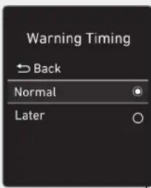
OTMA058089
- Setting Warning Timing
The driver can select the initial warning activation time on the LCD display.
Go to the 'User Settings → Driver Assistance → Warning Timing → Normal/Later'.
The options for the initial Forward Collision Warning includes the following:
- Normal:
When this option is selected, the initial Forward Collision Warning is activated sensitively. If you feel the warning activates too early, set the Forward Collision Warning to 'Later'.
Even though, 'Normal' is selected if the front vehicle suddenly stops the initial warning activation time may not seem fast.
- Later:
When this option is selected, the initial Forward Collision Warning is activated later than normal. This setting reduces the amount of distance between the vehicle, pedestrian ahead before the initial warning occurs.
Select 'Later' when traffic is light and when driving speed is slow.

Information
If you change the warning timing, the warning time of other systems may change. Always be aware before changing the warning timing.
Prerequisite for activation
The FCA system is on and ready when 'Active Assist' or 'Warning Only' under Forward Safety is selected in the LCD display and when the following prerequisites are satisfied:
- ESC (Electronic Stability Control) is on.
- Vehicle speed is over 5 mph (8 km/h) (The FCA is only activated within a certain speed range).
- The system detects a pedestrian or a vehicle in front, which may collide with your vehicle. However, FCA may not be activated or may only sound a warning alarm depending on the driving or vehicle conditions.

WARNING
• To avoid driver distractions, do not attempt to set or cancel the FCA while driving the vehicle. Always completely stop the vehicle at a safe place before setting or canceling the system.
• FCA automatically activates upon placing the ignition switch to the ON position. The driver can deactivate FCA by canceling the system setting in the cluster LCD display.
• FCA automatically deactivates upon canceling ESC. When ESC is canceled, FCA cannot be activated in the cluster LCD display. In this situation, the FCA warning light will illuminate which is normal.
FCA Warning Message and Brake Control
FCA produces warning messages, warning alarms, and emergency braking based on the level of risk of a frontal collision, such as when a vehicle ahead suddenly brakes, or when the system detects that a collision with a pedestrian is imminent.
Collision Warning (First and second warning)
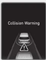
OLX2059026N
- The warning message appears on the cluster LCD display with a warning chime.
- Your vehicle speed may decelerate moderately.
-
If FCA detects a vehicle in front, the system operates when your vehicle speed is between 5 mph (8 km/h) and 100 mph (160km/h). Maximum vehicle speed may decrease depending on the condition of the vehicle ahead and surroundings.
-
If FCA detects a pedestrian in front, the system operates when your vehicle speed is between 5 mph (8 km/h) and 55 mph (90 km/h). Maximum vehicle speed may decrease depending on the condition of the vehicle ahead and surroundings.
- If you select 'Warning only' for the system setting, the FCA system activates and produces only warning alarms in accordance with the collision risk levels. You should control the brake directly because the FCA system will not control the brake.
Emergency Braking (Third warning)
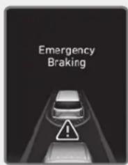
OLX2059027N
- The warning message appears on the cluster LCD display with a warning chime.
- Additionally, some vehicle system intervention occurs by the engine management system to help decelerate the vehicle.
-
The brake control is maximized just before a collision, reducing impact when it strikes a forward vehicle.
-
If FCA detects a vehicle in front, the system operates when your vehicle speed is above 5 mph (8 km/h) and 50 mph (80 km/h) or under. Maximum vehicle speed may decrease depending on the condition of the vehicle ahead and surroundings.
- If FCA detects a pedestrian in front, the system operates when your vehicle speed is 5 mph (8 km/h) or above and under 45 mph (70 km/h). Maximum vehicle speed may decrease depending on the condition of the vehicle ahead and surroundings.
- If you select 'Warning only' for the system setting, the FCA system activates and produces only warning alarms in accordance with the collision risk levels. You should control the brake directly because the FCA system do not control the brake.
Brake operation
- In an urgent situation, the braking system enters into the ready status for prompt reaction against the driver's depressing the brake pedal.
- The FCA provides additional braking power for optimum braking performance, when the driver depresses the brake pedal.
- The braking control is automatically deactivated, when the driver sharply depresses the accelerator pedal, or when the driver abruptly operates the steering wheel.
- The FCA braking control is automatically canceled, when risk factors disappear.
CAUTION
- The driver should always use extreme caution while operating the vehicle, whether or not there is a warning message or alarm from the FCA system.
• After the brake control is activated, the driver must immediately depress the brake pedal and check the surroundings. The brake activation by the system lasts for about 2 seconds. - If any other warning sound such as seat belt warning chime is already generated, the Forward Collision-Avoidance Assist (FCA) system warning may not sound.
- Playing the vehicle audio system at high volume may prevent occupants from hearing the system warning sounds.
WARNING
The FCA braking control cannot completely stop the vehicle nor avoid all collisions. The driver should hold the responsibility to safely drive and control the vehicle.
WARNING
The FCA system logic operates within certain parameters, such as the distance from the vehicle, pedestrian ahead, the speed of the vehicle ahead, and the driver's vehicle speed. Certain conditions such as inclement weather and road conditions may affect the operation of the FCA system.
WARNING
Never deliberately drive dangerously to activate the system.
FCA Sensor
(Front Radar/Front Camera)
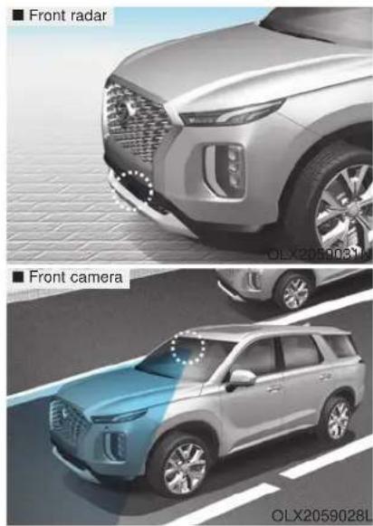
In order for the FCA system to operate properly, always make sure the sensor cover or sensor is clean and free of dirt, snow, and debris.
Dirt, snow, or foreign substances on the sensor cover or sensor may adversely affect the sensing performance of the sensor.
NOTICE
- Do not apply license plate frame or foreign objects such as a bumper sticker or a bumper guard near the sensor. Doing so may adversely affect the sensing performance of the radar.
• Always keep the sensor and cover clean and free of dirt and debris. - Use only a soft cloth to wash the vehicle. Do not spray pressurized water directly on the sensor or sensor cover.
-
Be careful not to apply unnecessary force on the sensor or sensor cover. If the sensor is forcibly moved out of proper alignment, the FCA system may not operate correctly. In this case, a warning message may not be displayed. Have the vehicle inspected by an authorized HYUNDAI dealer.
-
If the front bumper becomes damaged in the area around the sensor, the FCA system may not operate properly. Have the vehicle inspected by an authorized HYUNDAI dealer.
- Use only genuine HYUNDAI parts to repair or replace a damaged sensor or sensor cover. Do not apply paint to the sensor cover.
- NEVER install any accessories or stickers on the front windshield, or tint the front windshield.
- NEVER place any reflective objects (i.e. white paper, mirror) over the crash pad. Any light reflection may prevent the system from functioning properly.
- Pay extreme caution to keep the camera dry.
- NEVER disassemble the camera assembly, or apply any impact on the camera assembly.
NOTICE
- If the sensor is forcibly moved out of proper alignment, the FCA system may not operate correctly. In this case, a warning message may not be displayed. Have the vehicle inspected by an authorized HYUNDAI dealer.
i Information
Have the system checked by an authorized HYUNDAI dealer when:
• The windshield glass is replaced.
- The radar sensor or cover gets damaged or replaced.
Warning message and warning light
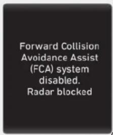
OIK057090L
Forward Collision-Avoidance Assist (FCA) system disabled.
Radar blocked
When the sensor cover is covered with dirt, snow, or debris, the FCA system operation may not be able to detect other vehicles. If this occurs, a warning message will appear on the LCD display.
The system will operate normally when such dirt, snow or debris is removed.
FCA may not properly operate in an area (e.g. open terrain) where any objects or vehicles are not detected after turning on the engine.
WARNING
The FCA system may not activate according to road conditions, inclement weather, driving conditions or traffic conditions.
System Malfunction
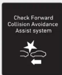
OIK057091L
Check Forward Collision-Avoidance Assist system
- When FCA is not working properly, the FCA warning light ( ^A ) will illuminate and the warning message will appear for a few seconds. After the message disappears, the master warning light ( ^A ) will illuminate. In this case, have the vehicle inspected by an authorized HYUNDAI dealer.
- The FCA warning message may appear along with the illumination of the ESC (Electronic Stability Control) warning light.
Both FCA warning light and warning message will disappear once the ESC warning light issue is resolved.
WARNING
- FCA is only a supplemental system for the driver's convenience. It is the driver's responsibility to control the vehicle operation. Do not solely depend on the FCA system. Rather, maintain a safe braking distance, and, if necessary, depress the brake pedal to reduce the driving speed or to stop the vehicle.
- In certain instances and under certain driving conditions, the FCA system may activate prematurely. This initial warning message appears on the LCD display with a warning chime.
Also due to sensing limitations, in certain situations, the front radar sensor or camera recognition system may not detect the vehicle, pedestrian ahead. The FCA system may not activate and the warning message may not be displayed.
- If there is a malfunction with the FCA system, the Forward Collision avoidance assist system is not applied even though the braking system is operating normally.
- If the vehicle in front stops suddenly, you may have less control of the brake system. Therefore, always keep a safe distance between your vehicle and the vehicle in front of you.
-
The FCA system may activate during braking and the vehicle may stop suddenly shifting loose objects toward the passengers. Always keep loose objects secured.
-
The FCA system may not activate if the driver applies the brake pedal to avoid collision.
- The brake control may be insufficient, possibly causing a collision, if a vehicle in front abruptly stops. Always pay extreme caution.
- The FCA system may not activate according to the road conditions, inclement weather, driving conditions or traffic conditions.
- Occupants may get injured, if the vehicle abruptly stops by the activated FCA system. Pay extreme caution.
• The FCA system operates only to detect vehicles, pedestrian in front of the vehicle.
WARNING
- The FCA system operates only to help detect vehicles or pedestrians in front of the vehicle.
- The FCA system does not operate when the vehicle is in reverse.
- The FCA system is not designed to detect other objects on the road such as animals.
- The FCA system does not detect vehicles in the opposite lane.
- The FCA system does not detect cross traffic vehicles that are approaching.
- The FCA system cannot detect the cross traffic cyclist that are approaching.
- The FCA system cannot detect vehicles that are stopped vertically to your vehicle at a intersection or dead end street.
In these cases, you must maintain a safe braking distance, and if necessary, depress the brake pedal to reduce the driving speed in order to maintain a safe distance or to stop the vehicle.
Limitations of the System
The Forward Collision Avoidance Assist (FCA) system is designed to monitor the vehicle ahead or a pedestrian on the roadway through radar signals and camera recognition to warn the driver that a collision is imminent, and if necessary, apply emergency braking.
In certain situations, the radar sensor or the camera may not be able to detect the vehicle, pedestrian ahead. In these cases, the FCA system may not operate normally. The driver must pay careful attention in the following situations where the FCA operation may be limited.
Detecting vehicles
The sensor may be limited when:
- The system may not operate for 15 seconds after the engine is started or the camera is initialized
- The radar sensor or camera is covered with a foreign object or debris
- The camera lens is contaminated due to tinted, filmed or coated windshield, damaged glass, or stuck of foreign matter (sticker, bug, etc.) on the glass
- Inclement weather such as heavy rain or snow obscures the field of view of the radar sensor or camera
- There is interference by electromagnetic waves
- There is severe irregular reflection from the radar sensor
- The radar/camera sensor recognition is limited
-
The vehicle in front is too small to be detected (for example a motorcycle or a bicycle, etc.)
-
The vehicle in front is an oversize vehicle or trailer that is too big to be detected by the camera recognition system (for example a tractor trailer, etc.)
- The camera's field of view is not well illuminated (either too dark or too much reflection or too much backlight that obscures the field of view)
- The vehicle in front does not have their rear lights properly turned ON or their rear lights are located unusually
- The outside brightness changes suddenly, for example when entering or exiting a tunnel
• Light coming from a street light or an oncoming vehicle is reflected on a wet road surface such as a puddle in the road - The field of view in front is obstructed by sun glare
- The windshield glass is fogged up; a clear view of the road is obstructed
-
The vehicle in front is driving erratically
-
The vehicle is on unpaved or uneven rough surfaces, or road with sudden gradient changes
- The vehicle is driven near areas containing metal substances as a construction zone, railroad, etc.
- The vehicle drives inside a building, such as a basement parking lot
- The camera does not recognize the entire vehicle in front
• The camera is damaged - The brightness outside is too low such as when the headlamps are not on at night or the vehicle is going through a tunnel
- The shadow is on the road by a median strip, trees, etc.
- The vehicle drives through a toll-gate.
- The rear part of the vehicle in front is not normally visible (the vehicle turns in other direction or the vehicle is overturned.)
- The adverse road conditions cause excessive vehicle vibrations while driving
• The sensor recognition changes suddenly when passing over a speed bump
- The vehicle in front is moving vertically to the driving direction
- The vehicle in front is stopped vertically
• The vehicle in front is driving towards your vehicle or reversing
• You are on a roundabout and the vehicle in front circles
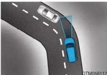
natural_image
Top-down view of a curved road with two cars, one blue and one silver, connected by a sensor or sensor (no text or symbols visible)OTM058073
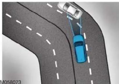
natural_image
Top-down view of a car on a curved road with two cars ahead, one in blue and one in white (no text or symbols)- Driving on a curve
The performance of the FCA system may be limited when driving on a curved road.
In certain instances on a curved road, the FCA system may activate prematurely.
Also, in certain instances the front radar sensor or camera recognition system may not detect the vehicle traveling on a curved road.
In these cases, the driver must maintain a safe braking distance, and if necessary, depress the brake pedal to reduce your driving speed in order to maintain a safe distance.
The FCA system may recognize a vehicle in the next lane when driving on a curved road.
In this case, the system may unnecessarily alarm the driver and apply the brake.
Always pay attention to road and driving conditions, while driving. If necessary, depress the brake pedal to reduce your driving speed in order to maintain a safe distance.
Also, when necessary depress the accelerator pedal to prevent the system from unnecessarily decelerating your vehicle.
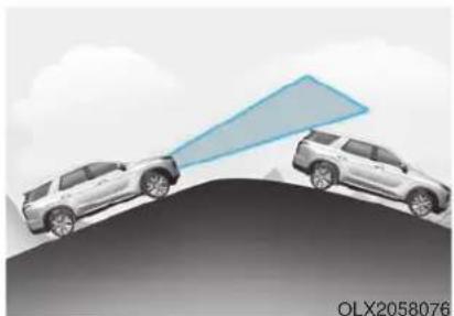
natural_image
Two SUVs on a curved surface with a blue triangular arrow pointing toward them, no text or symbols present.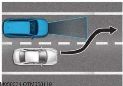
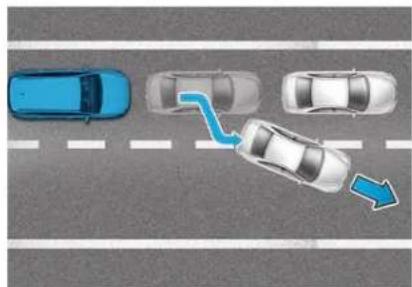
natural_image
Top-down view of a multi-lane road intersection with cars and a blue arrow indicating direction (no text or symbols)- Driving on a slope
The performance of the FCA decreases while driving upward or downward on a slope, not recognizing the vehicle in front in the same lane. It may unnecessarily produce the warning message and the warning alarm, or it may not produce the warning message and the warning alarm at all.
When the FCA suddenly recognizes the vehicle in front while passing over a slope, you may experience sharp deceleration.
Always keep your eyes forward while driving upward or downward on a slope, and, if necessary, depress the brake pedal to reduce your driving speed in order to maintain distance.
- Changing lanes
When a vehicle changes lanes in front of you, the FCA system may not immediately detect the vehicle, especially if the vehicle changes lanes abruptly. In this case, you must maintain a safe braking distance, and if necessary, depress the brake pedal to reduce your driving speed in order to maintain a safe distance.
When driving in stop-and-go traffic, and a vehicle in front of you merges out of the lane, the FCA system may not immediately detect the new vehicle that is now in front of you. In this case, you must maintain a safe braking distance, and if necessary, depress the brake pedal to reduce your driving speed in order to maintain a safe distance.
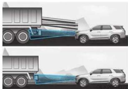
natural_image
Diagram showing two scenarios of a truck spraying water onto a car, with no text or symbols present.- Detecting the vehicle in front of you. If the vehicle in front of you has cargo that extends rearward from the cab, or when the vehicle in front of you has higher ground clearance, additional special attention is required. The FCA system may not be able to detect the cargo extending from the vehicle. In these instances, you must maintain a safe braking distance from the rearmost object, and if necessary, depress the brake pedal to reduce your driving speed in order to maintain distance.
Detecting pedestrians
The sensor may be limited when:
- The pedestrian is not fully detected by the camera recognition system, for example, if the pedestrian is leaning over or is not fully walking upright
- The pedestrian is moving very quickly or appears abruptly in the camera detection area
- The pedestrian is wearing clothing that easily blends into the background, making it difficult to be detected by the camera recognition system
- The outside lighting is too bright (e.g. when driving in bright sunlight or in sun glare) or too dark (e.g. when driving on a dark rural road at night)
- It is difficult to detect and distinguish the pedestrian from other objects in the surroundings, for example, when there is a group of pedestrians or a large crowd
- There is an item similar to a person's body structure
• The pedestrian is small
• The pedestrian has impaired mobility
• The sensor recognition is limited
• The radar sensor or camera is covered with a foreign object or debris
- The camera lens is contaminated due to tinted, filmed or coated windshield, damaged glass, or stuck of foreign matter (sticker, bug, etc.) on the glass
• The brightness outside is too low such as when the headlamps are not on at night or the vehicle is going through a tunnel
- Inclement weather such as heavy rain or snow obscures the field of view of the radar sensor or camera
• Light coming from a street light or an oncoming vehicle is reflected on a wet road surface such as a puddle in the road
- The field of view in front is obstructed by sun glare
- The windshield glass is fogged up; a clear view of the road is obstructed
• The adverse road conditions cause excessive vehicle vibrations while driving
- The sensor recognition changes suddenly when passing over a speed bump
- You are on a roundabout
- When the pedestrian suddenly interrupts in front of the vehicle
- When there is any other electromagnetic interference
- When the construction area, rail or other metal object is near the cyclist
WARNING
- Do not use the Forward Collision Avoidance Assist (FCA) system when towing a vehicle. Application of the FCA system while towing may adversely affect the safety of your vehicle or the towing vehicle.
- Use extreme caution when the vehicle in front of you has cargo that extends rearward from the cab, or when the vehicle in front of you has higher ground clearance.
-
The FCA system is designed to help detect and monitor the vehicle ahead to help detect a pedestrian in the roadway through radar signals and camera recognition. It is not designed to detect bicycles, motorcycles, or smaller wheeled objects such as luggage bags, shopping carts, or strollers.
-
Never try to test the operation of the FCA system. Doing so may cause severe injury or death.
i Information
In some instances, the FCA system may be canceled when subjected to electromagnetic interference.
i Information
This device complies with Part 15 of the FCC rules.
Operation is subject to the following two conditions:
- This device may not cause harmful interference.
- This device must accept any interference received, including interference that may cause undesired operation.
BLIND-SPOT COLLISION WARNING/BLIND-SPOT COLLISION-AVOIDANCE ASSIST (IF EQUIPPED)
System Description
Blind-Spot Collision Warning (BCW)
The Blind-Spot Collision Warning (BCW) system uses radar sensors in the rear bumper to monitor and warn the driver when it detects an approaching vehicle in the driver's blind spot area.
1) Blind-Spot Area
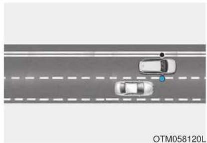
natural_image
Top-down view of a multi-lane road with two cars, one marked with a blue circle and the other with a blue dot (no text or symbols on the vehicles)The blind spot detection range varies relative to vehicle speed.
Note that if your vehicle is traveling much faster than the vehicles around you, the warning will not occur.
2) Closing at high speed
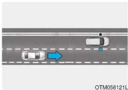
natural_image
Top-down view of a multi-lane road with two cars, one marked with a blue arrow (no text or symbols on the vehicles)The Lane Change Assist feature will alert you when it detects a vehicle is approaching in an adjacent lane at a high rate of speed. If the driver activates the turn signal when the system detects an oncoming vehicle, the system sounds an audible alert.
Blind-Spot Collision-Avoidance Assist (BCA)
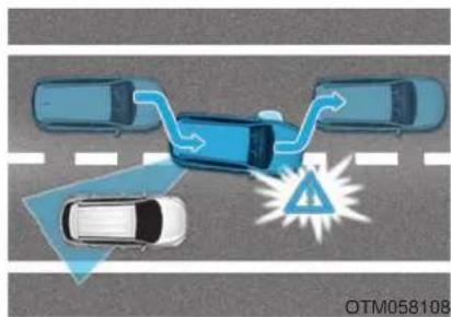
natural_image
Top-down diagram of a car accident showing a blue car on a road with a warning triangle and traffic flow arrows (no text or symbols)The Blind-Spot Collision-Avoidance Assist (BCA) system helps detect the front lane through the camera installed on the upper front wind-shield and helps detect the side/rear areas through radar sensors.
The Blind-Spot Collision-Avoidance Assist system may activate the Electronic Stability Control (ESC) if there is a possible collision with an approaching vehicle while changing lanes. It is to help mitigate the collision risk or collision damage.
WARNING
• Always be aware of road conditions while driving and be alert for unexpected situations even though the Blind-Spot Collision Warning system and Blind-Spot Collision-Avoidance Assist system are operating.
- The Blind-Spot Collision Warning (BCW) system and Blind-Spot Collision-Avoidance Assist (BCA) system are supplemental systems to assist you. Do not entirely rely on the systems. Always pay attention, while driving, for your safety.
- The Blind-Spot Collision Warning (BCW) system and Blind-Spot Collision-Avoidance Assist (BCA) system are not substitutes for proper and safe driving. Always drive safely and use caution when changing lanes or backing up the vehicle.
The Blind-Spot Collision Warning (BCW) system and Blind-Spot Collision-Avoidance Assist (BCA) system may not detect every object alongside the vehicle.
System Setting and Operation
System setting
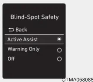
- Setting Blind-Spot Safety function The driver can activate the system by placing the ignition switch to the ON position and by selecting 'User Settings →Driver Assistance →Blind-Spot Safety'
-
BCA and BCW turn on and are ready to be operated when 'Active Assist' is selected. Then, if a vehicle approaches the driver's blind spot area a warning sounds or braking power is applied.
-
BCW turns on and is ready to be operated when 'Warning Only' is selected. Then, if a vehicle approaches the driver's blind spot area a warning sounds but braking is not applied.
- The system is deactivated and the indicator on the BCW/BCA button is turned off when 'Off' is selected.
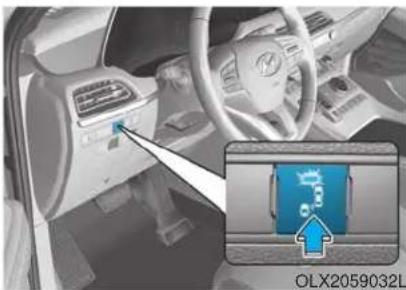
natural_image
Interior view of a car dashboard with a highlighted control panel and an inset showing a blue logo (no readable text or symbols)- If you press the BCW/BCA switch while 'Active Assist' or 'Warning Only' is selected the indicator on the switch will turn off and the system will deactivate.
- If you press the BCW/BCA switch while the system is canceled the indicator on the button illuminates and the system activates.
When the system is initially turned on and when the engine is turned off then on again while the system is in activation, the warning light will illuminate for 3 seconds on the outer side view mirror.
- If the engine is turned off then on again, the system maintains the last setting.
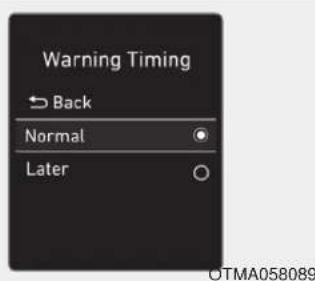
- Selecting Warning Timing The driver can select the initial warning activation time in the User Settings in the LCD display by selecting 'User Settings →Driver Assistance →Warning Timing'.
- The options for the initial Blind-Spot Collision Warning includes the following:
- Normal:
When this option is selected, the initial Blind-Spot Collision Warning is activated normally. If this setting feels sensitive, change the option to 'Later'.
The warning activation time may feel late if a vehicle at the side or rear abruptly accelerates.
- Later:
Select this warning activation time when the traffic is light and you are driving at low speeds.
i Information
If you change the warning timing, the warning time of other systems may change. Always be aware before changing the warning timing.
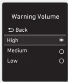
OTMA058094
- Setting Warning Volume
The driver can select the warning volume of Blind-Spot Collision Warning in the User Settings in the LCD display by selecting 'User Settings →Driver Assistance →Warning Volume →High/Medium/Low'.
For more details, refer to "LCD Display" in chapter 3.
i Information
If you change the warning volume, the warning volume of other systems may change. Always be aware before changing the warning volume.
Operating Conditions
The system enters the ready status, when 'Active Assist' or 'Warning Only' is selected and the following conditions are satisfied:
- Active Assist
- Warning Only
1) The Blind-Spot Collision-Avoidance Assist system will operate When:
- Vehicle speed is between 40 mph and 110 mph (60 km/h and 180 km/h).
- The system detects both of the lane lines.
- An approaching vehicle is detected next to or behind your vehicle.
2) The Blind-Spot Collision Warning system will operate When:
The vehicle speed is above approximately 20 mph (30 km/h).
1) The Blind-Spot Collision Warning system will activate When:
- The vehicle speed is approximately 20 mph (30 km/h).
- The Blind-Spot Collision-Avoidance Assist system is not activated when "Warning Only" is selected for the system setting.
Warning and System Control
Blind-Spot Collision Warning (BCW) system
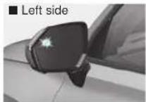
First stage alert
If a vehicle is detected within the boundary of the system, a warning light will illuminate on the outer side view mirror and the head up display (if equipped).
If the detected vehicle is no longer within the blind spot area, the warning will turn off according to the driving conditions of the vehicle.
natural_image
Side view of a car with a black mirror and star-shaped patch, labeled 'Left side' (no other text or symbols)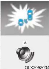
natural_image
Illustration of a speaker emitting sound waves, labeled 'A', with model number OLX2058034 below (no text or symbols on the diagram itself)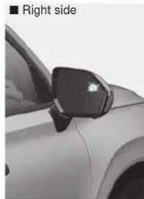
natural_image
Side view of a car with a black mirror on the side (no text or symbols visible)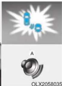
natural_image
Two abstract diagrams: top shows a explosion with blue droplets, bottom shows a speaker icon labeled 'OLX2058035' (no text or symbols on the figures themselves)A: Warning sound
Second stage alert
A warning chime to alert the driver will activate when:
- A vehicle has been detected in the blind spot area by the radar system AND.
- The turn signal is applied (same side as where the vehicle is being detected).
When this alert is activated, the warning light on the outer side view mirror and the head up display (if equipped) will also blink. And a warning chime will sound.
If you turn off the turn signal indicator, the second stage alert will be deactivated.
If the detected vehicle is no longer within the blind spot area, the warning will turn off according to the driving conditions of the vehicle.
WARNING
- The warning light on the outer side view mirror will illuminate whenever a vehicle is detected at the rear side by the system.
To avoid accidents, do not focus only on the warning light and neglect to see the surroundings of the vehicle. - Drive safely even though the vehicle is equipped with a Blind-Spot Collision Warning (BCW) system. Do not solely rely on the system but check your surroundings before changing lanes or backing the vehicle up.
- The system may not alert the driver in some situations due to system limitations so always check your surroundings while driving.
CAUTION
• Always pay attention to road and traffic conditions while driving, whether or not the warning light on the outer side view mirror illuminates or there is a warning alarm.
- Playing the vehicle audio system at high volume may prevent occupants from hearing the Blind-Spot Collision Warning system warning sounds.
- If any other warning sound such as seat belt warning chime is already generated, the Blind-Spot Collision Warning (BCW) system warning may not sound.
Blind-Spot Collision-Avoidance Assist (BCA) system
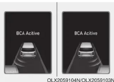
OLX2059104N/OLX2059103N
The Blind-Spot Collision-Avoidance Assist (BCA) system may apply braking power, when an approaching vehicle is detected within a certain distance next to or behind your vehicle.
In this situation, the system gently apply braking power on the tire, which is located in the opposite side of the possible-colliding point. The instrument cluster will inform the driver of the system activation.
Blind-Spot Collision-Avoidance Assist (BCA) system is automatically deactivated when:
- The vehicle drives a certain distance away
- The vehicle direction is changed against the possible-colliding point
- The steering wheel is abruptly moved
- The brake pedal is depressed
- After a certain period of time
The driver should drive the vehicle in the middle of the vehicle lanes to keep the system in the ready status.
When the vehicle drives too close to one side of the vehicle lanes, the system may not properly operate.
In addition, the system may not properly control your vehicle in accordance with driving situations. Thus, always pay close attention to road conditions.
WARNING
- The driver is responsible for accurate steering.
- Do not unnecessarily operate the steering wheel, when the Blind-Spot Collision-Avoidance Assist System is in operation.
• Always pay attention to road and traffic conditions while driving. The Blind-Spot Collision-Avoidance Assist system may not operate or unnecessarily operate depending on certain situations. - The Blind-Spot Collision-Avoidance Assist system is not a substitute for safe driving practices, but is a supplemental system only. It is the responsibility of the driver to always drive cautiously to prevent unexpected and sudden situations from occurring. Pay attention to road conditions at all times.
Detecting Sensor (Camera and Radar)
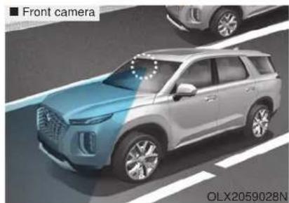
natural_image
Front view of a modern SUV on a road, no visible text or symbols on the vehicle itself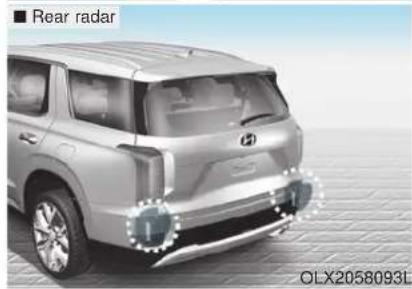
Front camera
The front camera function as a sensor detecting the lane. If the sensor is covered with snow, rain or foreign substance, the system may temporarily be canceled and not work properly. Always keep the sensor clean.
Refer to Lane Keeping Assist (LKA) System for cautions for the front camera sensor.
Rear radar
The rear radars are located inside the rear bumper for detecting the side and rear areas. Always keep the rear bumper clean for proper operation of the system.
NOTICE
- The system may not work properly when the bumper has been damaged, or if the rear bumper has been replaced or repaired.
- The sensing range differs somewhat according to the width of the road. When the road is narrow, the system may detect other vehicles in the next lane.
- The system may turn off if interfered by strong electromagnetic waves.
• Always keep the sensors clean. - NEVER disassemble the sensor component or apply any impact on the sensor component.
-
Be careful not to apply unnecessary force on the radar sensor or sensor cover. If the sensor is forcibly moved out of proper alignment, the system may not operate correctly.
In this case, a warning message may not be displayed. Have the vehicle inspected by an authorized HYUNDAI dealer. -
Do not apply foreign objects such as a bumper sticker or a bumper guard near the radar sensor or apply paint to the sensor area. Doing so may adversely affect the performance of the sensor.
- NEVER install any accessories or stickers on the front windshield, or tint the front windshield.
- Pay extreme caution to keep the camera sensor dry.
- NEVER place any reflective objects (i.e. white paper, mirror) over the crash pad. Any light reflection may prevent the system from functioning properly.
Warning message
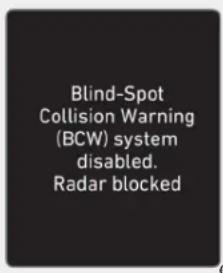
OIK057092L
Blind-Spot Collision Warning (BCW) system disabled.
Radar blocked
This warning message may appear When:
- One or both of the sensors on the rear bumper is blocked by dirt or snow or a foreign object.
- Driving in rural areas where the sensor does not detect another vehicle for an extended period of time.
- When there is inclement weather such as heavy snow or rain.
If any of these conditions occur, the light on the BCW/BCA switch and the system will turn off automatically.
When the BCW canceled warning message is displayed in the cluster, check to make sure that the rear bumper is free from any dirt or snow in the areas where the sensor is located. Remove any dirt, snow, or foreign material that could interfere with the radar sensors.
After any dirt or debris is removed, the system should operate normally after about 10 minutes of driving the vehicle.
If the system still does not operate normally have your vehicle inspected by an authorized HYUNDAI dealer.
i Information
Turn off the BCW, BCA and RCCW system when a trailer or carrier is installed.
- Press the BCW/BCA switch (the indicator on the switch will turn off)
- Deactivate the RCCW system by deselecting
'User Settings → Driver Assistance → Parking Safety → Rear Cross-Traffic Collision Warning' (if equipped)
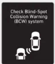
OTM058151L OLX2049137N
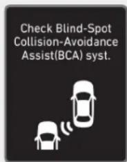
Check Blind-Spot Collision Warning (BCW) system
If there is a problem with the BCW system, a warning message will appear and the light on the switch will turn off. The system will turn off automatically. BCA will not operate also if the BCW system turns off due to malfunction. Have your vehicle inspected by an authorized HYUNDAI dealer.
Check Blind-Spot Collision-Avoidance Assist (BCA) system
If there is a problem with the BCA system, a warning message will appear. The system will turn off automatically. BCW will still operate even if the BCA system turns off due to malfunction. Have your vehicle inspected by an authorized HYUNDAI dealer to use BCA system.
Limitations of the System
The driver must be cautious in the below situations because the system may not detect other vehicles or objects in certain circumstances:
- When a trailer or carrier is installed.
- The vehicle driven in inclement weather such as heavy rain or snow.
- The sensor is polluted with rain, snow, mud, etc.
- The rear bumper where the sensor is located is covered with a foreign object such as a bumper sticker, a bumper guard, a bike rack, etc.
- The rear bumper is damaged, or the sensor is out of the original default position.
- The vehicle height gets lower or higher due to heavy loading in a luggage compartment, abnormal tire pressure, etc.
- When the temperature of the rear bumper is high.
-
When the sensors are blocked by other vehicles, walls or parking-lot pillars.
-
The vehicle is driven on a curved road.
- The vehicle is driven through a toll-gate.
- The road pavement (or the peripheral ground) abnormally contains metallic components (i.e. possibly due to subway construction).
- There is a fixed object near the vehicle, such as a guardrail.
- While going down or up a steep road where the height of the lane is different.
- Driving on a narrow road where trees or grass or overgrown.
- Driving in rural areas where the sensor does not detect another vehicle or structure for an extended period of time.
- Driving on a wet road.
- Driving on a road where the guardrail or wall is in double structure.
- A big vehicle is near such as a bus or truck.
-
When the other vehicle approaches very close.
-
When the other vehicle passes at a very fast speed.
- While changing lanes.
- If the vehicle has started at the same time as the vehicle next to you and has accelerated.
- When the vehicle in the next lane moves two lanes away from you OR when the vehicle two lanes away moves to the next lane from you.
- A motorcycle or bicycle is near.
- A flat trailer is near.
- If there are small objects in the detecting area such as a shopping cart or a baby stroller.
- If there is a low height vehicle such as a sports car.
• The brake pedal is depressed. - ESC (Electronic Stability Control) is activated.
- ESC (Electronic Stability Control) malfunctions.
-
The tire pressure is low or a tire is damaged.
• The brake is reworked. -
The vehicle abruptly changes driving direction.
- The vehicle makes sharp lane changes.
• The vehicle sharply stops.
• Temperature is extremely low around the vehicle. - The vehicle severely vibrates while driving over an uneven//bumpy road, or concrete patch.
- The vehicle drives on a slippery surface due to snow, water puddle, or ice.
- The Lane Keeping Assist (LKA) does not operate normally.
For more details refer to "Lane Keeping Assist (LKA) system" in this chapter.
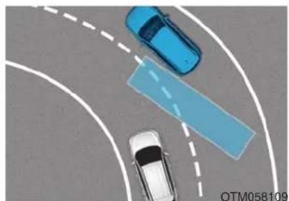
natural_image
Top-down view of a car and two blue cars on a curved road, with a blue rectangular overlay (no text or symbols)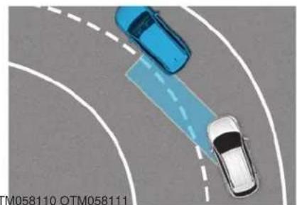
natural_image
Top-down view of two cars on a curved road with a blue lane overlay (no text or symbols)- Driving on a curve
The BCW and BCA systems may not operate properly when driving on a curved road. In certain instances, the system may not detect the vehicle in the next lane. Always pay attention to road and driving conditions, while driving.
The BCW and BCA systems may not operate properly when driving on a curved road. In certain instances, the system may recognize a vehicle in the same lane.
Always pay attention to road and driving conditions, while driving.
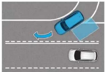
natural_image
Top-down view of a car on a road with two cars, one moving toward the lane and another curved arrow indicating motion (no text or symbols)- Driving where the road is merging/dividing
The BCW and BCA systems may not operate properly when driving where the road is merging/dividing. In certain instances, the system may not detect the vehicle in the next lane.
Always pay attention to road and driving conditions, while driving.
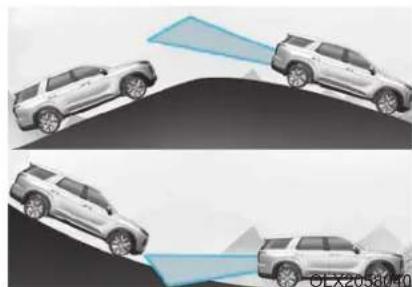
natural_image
Two identical illustrations of a car with a blue light beam projecting onto a curved surface, no text or symbols present.OLX2059039N OIX2059041N
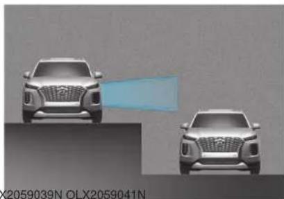
natural_image
Two silver SUVs on a flat surface, one with a light blue arrow pointing to the side (no text or symbols visible)- Driving on a slope
The BCW and BCA systems may not operate properly when driving on a slope. In certain instances the system may not detect the vehicle in the next lane.
Also, in certain instances, the system may recognize the ground or structures.
Always pay attention to road and driving conditions, while driving.
- Driving where the heights of the lanes are different
The BCW and BCA systems may not operate properly when driving where the heights of the lanes are different.
In certain instances, the system may not detect the vehicle on a road with different lane heights (i.e. underpass joining section, grade separated intersections, etc.).
Always pay attention to road and driving conditions, while driving.
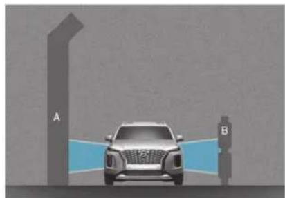
natural_image
Illustration of a car parked under two parking stations labeled A and B, with no visible text or symbols on the car or background.- Driving where there is a structure beside the road
The BCW and BCA systems may not operate properly when driving where there is structure beside the road.
In certain instances, the system may recognize the structures (i.e. noise barriers, guardrail, double guardrail, median strip, bollard, street light, road sign, tunnel wall, etc.) beside the road.
Always pay attention to road and driving conditions, while driving.
i Information
This device complies with Part 15 of the FCC rules.
Operation is subject to the following two conditions:
- This device may not cause harmful interference.
- This device must accept any interference received, including interference that may cause undesired operation.
REAR CROSS-TRAFFIC COLLISION WARNING (RCCW) / REAR CROSS-TRAFFIC COLLISION-AVOIDANCE ASSIST (RCCA)
System Description
Rear Cross-Traffic Collision Warning (RCCW) system
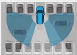
natural_image
Top-down view of a car layout with multiple lanes and a central blue car (no text or symbols)OTM058092
The Rear Cross-Traffic Collision Warning (RCCW) system uses radar sensors to monitor the approaching cross traffic from the left and right side of the vehicle when your vehicle is in reverse.
The blind spot detection range varies relative to the approaching vehicle speed.
Rear Cross-Traffic Collision-Avoidance Assist (RCCA) system
The Rear Cross-Traffic Collision-Avoidance Assist (RCCA) system monitors approaching cross traffic from the left and right side of the vehicle when your vehicle is in reverse.
The Rear Cross-Traffic Collision-Avoidance Assist (RCCA) system may activate the Electronic Stability Control (ESC) in accordance with a possible collision with an approaching vehicle. It is to lower the possible collision risk or mitigate the possible collision damage.
WARNING
- Always be aware of road and traffic conditions while driving and be alert for unexpected situations even though the Rear Cross-Traffic Collision Warning system and Rear Cross-Traffic Collision-Avoidance Assist system are operating.
- The Rear Cross-Traffic Collision Warning system and Rear Cross-Traffic Collision-Avoidance Assist system are supplemental systems to assist you. Do not entirely rely on the systems. Always pay attention, while driving, for your safety.
- The Rear Cross-Traffic Collision Warning system and Rear Cross-Traffic Collision-Avoidance Assist system are not substitutes for proper and safe driving. Always drive safely and use caution when backing up the vehicle.
System Setting and Operation System setting
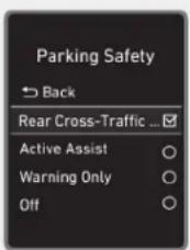
OLX2059108N
- Setting Parking Safety function
The driver can activate the systems by placing the ignition switch to the ON position and by selecting 'User Settings → Driver Assistance → Parking Safety → Rear Cross-Traffic Safety'. The RCCA and RCCW turn on and get ready to be activated when 'Rear Cross-Traffic Safety' is selected. - When the engine is turned off then on again, the systems will be ready to be operated.
- When the system is initially turned on and engine is turned off then on again, the warning light will illuminate for 3 seconds on the side view mirror.
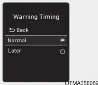
- Setting Warning Timing
The driver can select the initial warning activation time in the User Settings in the LCD display by selecting 'User Settings →Driver Assistance →Warning Timing'.
The options for the initial Rear Cross-Traffic Collision Warning includes the following:
- Normal:
When this option is selected, the initial Rear Cross-Traffic Collision Warning is activated normally. If this setting feels sensitive, change the option to 'Later'.
The warning activation time may feel late if the a vehicle at the side or rear abruptly accelerates.
- Later:
Select this warning activation time when the traffic is light and you are driving at low speeds.
i Information
If you change the warning timing, the warning time of other systems may change. Always be aware before changing the warning timing.
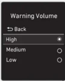
OTMA058094
- Setting Warning Volume
The driver can select the warning volume of the Rear Cross-Traffic Collision Warning by selecting 'User Settings →Driver Assistance →Warning Volume →High/Medium/Low'.
For more details, refer to "LCD Display" in chapter 3.
i Information
If you change the warning volume, the warning volume of other systems may change. Always be aware before changing the warning volume.
Operating conditions
To operate:
Go to the 'User Settings →Driver Assistance →Parking Safety →Rear Cross-Traffic Safety' in the cluster LCD display. The system will turn on and standby to activate.
The system will operate when vehicle speed is below 6 mph (10 km/h) and with the gear in R (Reverse).
* The system will not operate when the vehicle speed exceeds 6 mph (10 km/h). The system will operate again when the speed is below 6 mph (10 km/h).
The system's detecting range is approximately 1 – 65 ft. (0.5 – 20 m). An approaching vehicle will be detected if the vehicle speed is within 5 – 22.5 mph (8 – 36 km/h).
Note that the detecting range may vary under certain conditions. As always, use caution and pay close attention to your surroundings when backing up your vehicle.
Warning and System Control
Rear Cross-Traffic Collision Warning (RCCW) system
■ Left
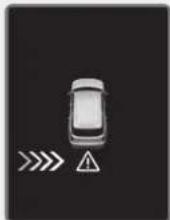
OLX2059042N
Right
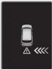
OLX2059043N
■ Left
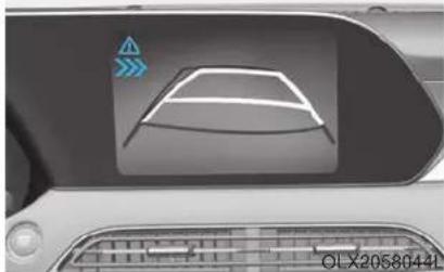
natural_image
Top-down view of a car dashboard with a white car silhouette and directional arrows (no text or symbols)Right
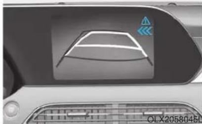
natural_image
Top-down view of a car dashboard with a white curved panel and a blue triangular icon (no text or symbols)If the vehicle detected by the sensors approaches from the rear left/right side of your vehicle, the warning chime will sound, the warning light on the outer side view mirror will blink and a warning will appear on the LCD display. If the rear view monitor system is in activation, a warning will also appear on the infotainment system screen.
The warning will stop when:
- the detected vehicle moves out of the sensing area or
- when the vehicle is right behind your vehicle or
- when the vehicle is not approaching your vehicle or
- when the other vehicle slows down.
Rear Cross-Traffic Collision-Avoidance Assist (RCCA) system
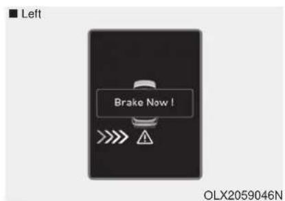
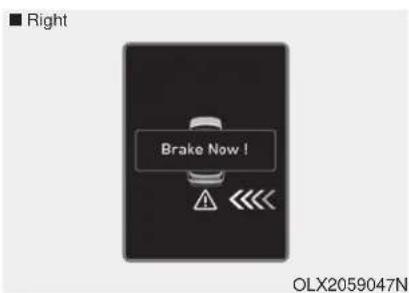
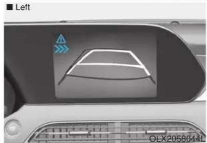
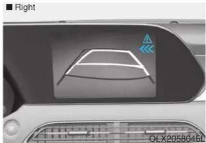
If the risk of collision is detected while the RCCW is generated, brake is controlled. The instrument cluster will inform the driver of the brake control. If the rear view monitor system is in activation, a message will also appear on the infotainment screen.
After the brake control is activated, the driver must immediately depress the brake pedal and check the surroundings.
- The brake activation by the system lasts for about 2 seconds.
The driver must pay attention as the brake is disengaged after 2 seconds. - The brake control by the system is canceled if the driver depresses the brake pedal with sufficient power.
- Brake control is activated once for each right/left approach after shifting the gear to R (Reverse).
The brake control may not operate properly according to the status of the ESC (Electronic Stability Control). The same warning message is displayed on the instrument cluster when :
- the ESC (Electronic Stability Control) warning light is on.
- the ESC (Electronic Stability Control) is engaged in a different function.

CAUTION
- When the operation condition of the Rear Cross-Traffic Collision Warning system is satisfied, the warning will occur every time a vehicle approaches the side or rear of your stopped (0 mph vehicle speed) vehicle.
- The system's warning may not operate properly if the left or right of your vehicle's rear bumper is blocked by a vehicle or obstacle.
• Always pay attention to road and traffic conditions while driving, whether or not the warning light on the outer side view mirror illuminates or there is a warning alarm.
- Playing the vehicle audio system at high volume may prevent occupants from hearing the system's warning sounds.
- If any other warning sound such as seat belt warning chime is already generated, the Rear Cross-Traffic Collision Warning system warning may not sound.

WARNING
- Drive safely even though the vehicle is equipped with a Rear Cross-Traffic Collision Warning system and Rear Cross-Traffic Collision-Avoidance Assist system. Do not solely rely on the system but check your surrounding when backing the vehicle up.
- The driver is responsible for accurate brake control.
• Always pay extreme caution while driving. The Rear Cross-Traffic Collision Warning system and Rear Cross-Traffic Collision-Avoidance Assist system may not operate properly or unnecessarily operate depending on traffic and driving conditions. - The Rear Cross-Traffic Collision-Avoidance Assist system is not a substitute for safe driving practices, but a convenience function only. It is the responsibility of the driver to always drive cautiously to prevent unexpected and sudden situations from occurring. Pay attention to the road conditions at all times.
Detecting Sensor
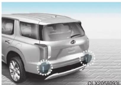
natural_image
Side profile of a silver SUV with visible engine and sensor components, no text or symbols presentThe rear radars are located inside the rear bumper for detecting the side and rear areas. Always keep the rear bumper clean for proper operation of the system.
NOTICE
- The system may not work properly when the bumper has been damaged, or if the rear bumper has been replaced or repaired.
- The system may turn off if interfered by electromagnetic waves.
• Always keep the sensors clean. - NEVER disassemble the sensor component or apply any impact on the sensor component.
- Be careful not to apply unnecessary force on the radar sensor or sensor cover. If the sensor is forcibly moved out of proper alignment, the system may not operate correctly. In this case, a warning message may not be displayed. Have the vehicle inspected by an authorized HYUNDAI dealer.
- Do not apply foreign objects such as a bumper sticker or a bumper guard near the radar sensor or apply paint to the sensor area. Doing so may adversely affect the performance of the sensor.
Warning message
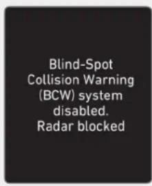
Blind-Spot Collision Warning (BCW) system disabled. Radar blocked
This warning message may appear when:
- One or both of the sensors on the rear bumper is blocked by dirt or snow or a foreign object.
- Driving in rural areas where the sensor does not detect another vehicle for an extended period of time.
- When there is inclement weather such as heavy snow or rain.
If any of these conditions occur, the light on the BCW/BCA switch and the system will turn off automatically.
When the BCW canceled warning message is displayed in the cluster, check to make sure that the rear bumper is free from any dirt or snow in the areas where the sensor is located. Remove any dirt, snow, or foreign material that could interfere with the radar sensors.
After any dirt or debris is removed, the system should operate normally after about 10 minutes of driving the vehicle.
If the system still does not operate normally have your vehicle inspected by an authorized HYUNDAI dealer.
i Information
Turn off the BCW and RCCW system when a trailer or carrier is installed.
- Press the BCW/BCA switch (the indicator on the switch will turn off)
- Deactivate the RCCW system by deselecting 'User Settings → Driver Assistance → Parking Safety → Rear Cross-Traffic Collision Warning'
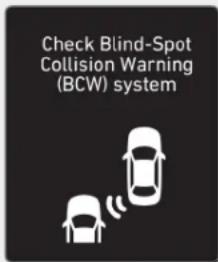
OTM058151L
Check Blind-Spot Collision Warning (BCW) system
If there is a problem with the BCW system, a warning message will appear and the light on the switch will turn off. The system will turn off automatically. RCCW and RCCA will not operate also if the BCW system turns off due to malfunction. Have your vehicle inspected by an authorized HYUNDAI dealer.
Limitations of the System
The driver must be cautious in the below situations because the system may not detect other vehicles or objects in certain circumstances:
- When a trailer or carrier is installed.
- The vehicle drives in inclement weather such as heavy rain or snow.
- The sensor is polluted with rain, snow, mud, etc.
- The rear bumper where the sensor is located is covered with a foreign object such as a bumper sticker, a bumper guard, a bike rack, etc.
- The rear bumper is damaged, or the sensor is out of the original default position.
- The vehicle height gets lower or higher due to heavy loading in a trunk, abnormal tire pressure, etc.
- When the temperature of the rear bumper is high.
-
When the sensors are blocked by other vehicles, walls or parking-lot pillars.
• The vehicle drives on a curved road. -
The road pavement (or the peripheral ground) abnormally contains metallic components (i.e. possibly due to subway construction).
- There is a fixed object near the vehicle, such as a guardrail.
- While going down or up a steep road where the height of the lane is different.
- Driving on a narrow road where trees or grass or overgrown.
- Driving in rural areas where the sensor does not detect another vehicle for an extended period of time.
- Driving on a wet road.
- Driving on a road where the guardrail or wall is in double structure.
- A big vehicle is near such as a bus or truck.
- When the other vehicle approaches very close.
- When the other vehicle passes at a very fast speed.
- While changing lanes.
-
If the vehicle has started at the same time as the vehicle next to you and has accelerated.
-
When the vehicle in the next lane moves two lanes away from you OR when the vehicle two lanes away moves to the next lane from you.
- A motorcycle or bicycle is near.
- A flat trailer is near.
- If there are small objects in the detecting area such as a shopping cart or a baby stroller.
- If there is a low height vehicle such as a sports car.
• The brake pedal is depressed. - ESC (Electronic Stability Control) is activated.
- ESC (Electronic Stability Control) malfunctions.
- The tire pressure is low or a tire is damaged.
• The brake is reworked.
• The vehicle sharply stops.
• Temperature is extremely low around the vehicle. - The vehicle severely vibrates while driving over an uneven/bumpy road, or concrete patch.
- The vehicle drives on a slippery surface due to snow, water puddle, or ice.
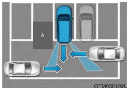
flowchart
graph TD
    A[" Lane A"] --> B[" Lane B"]
    B --> C[" Lane C"]
    style A fill:#f9f,stroke:#333
    style B fill:#bbf,stroke:#333
    style C fill:#dfd,stroke:#333
- Driving where there is a vehicle or structure near
The system may not operate properly when driving where there is a vehicle or structure near.
In certain instances, the system may not detect the vehicle approaching from behind and the warning or brake may not operate properly.
Always pay attention to your surrounding while driving.
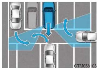
flowchart
graph TD
    A["Top Left Car"] --> B["Top Right Car"]
    B --> C["Bottom Left Car"]
    C --> D["Bottom Right Car"]
    D --> E["Top Left Road"]
    style A fill:#f9f,stroke:#333
    style B fill:#bbf,stroke:#333
    style C fill:#f9f,stroke:#333
    style D fill:#bbf,stroke:#333
    style E fill:#f9f,stroke:#333
OTM058104L OLX2058048
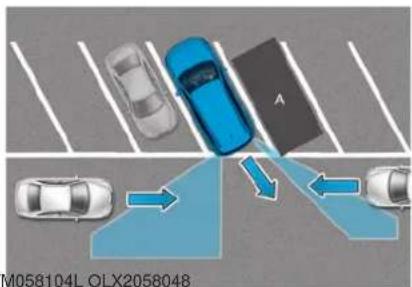
- When the vehicle is in a complex parking environment
The system may not operate properly when the vehicle is in a complex parking environment.
In certain instances, the system may not be able to exactly determine the risk of collision for the vehicles which are parking or pulling out near your vehicle (e.g. a vehicle escaping beside your vehicle, a vehicle parking or pulling out in the rear area, a vehicle approaching your vehicle making a turn, etc.).
If this occurs, the warning or brake may not operate properly.
- When the vehicle is parked diagonally
The system may not operate properly when the vehicle is parked diagonally.
In certain instances, when the diagonally parked vehicle is pulled out of the parking space, the system may not detect the vehicle approaching from the rear left/right of your vehicle. In this case, the warning or brake may not operate properly.
Always pay attention to your surrounding while driving.
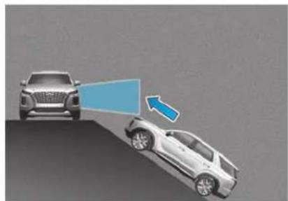
natural_image
Two cars, one frontal and one side, with a blue arrow pointing to the front view of the car (no text or symbols present)- When the vehicle is on/near a slope
The system may not operate properly when the vehicle is on/near a slope.
In certain instances, the system may not detect the vehicle approaching from the rear left/right and the warning or brake may not operate properly.
Always pay attention to your surrounding while driving.
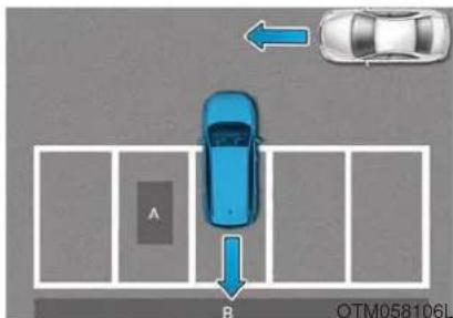
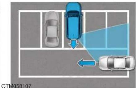
- Pulling into the parking space where there is a structure
The system may not operate properly when pulling in the vehicle to the parking space where there is a structure at the back or side of your vehicle.
In certain instances, when backing into the parking space, the system may falsely detect the vehicle moving in front of your vehicle. In this case, the warning or brake may operate.
Always pay attention to the parking space while driving.
- When the vehicle is parked rearward
If the vehicle is parked rearward and the sensor detects the another vehicle in the rear area of the parking space, the system can warn or control braking. Always pay attention to the parking space while driving.
i Information
This device complies with Part 15 of the FCC rules.
Operation is subject to the following two conditions:
-
This device may not cause harmful interference.
-
This device must accept any interference received, including interference that may cause undesired operation.
LANE FOLLOWING ASSIST (LFA) SYSTEM
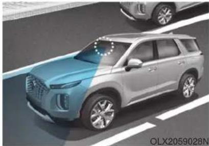
natural_image
Exterior view of a modern SUV (no signage or text visible)The Lane Following Assist (LFA) system helps detect lane markers on the road with a front view camera at the front windshield, and assists the driver's steering to help keep the vehicle between lanes.
WARNING
The Lane Following Assist (LFA) system is not a substitute for safe driving practices, but a convenience function. It is the responsibility of the driver to always be aware of the surroundings and steer the vehicle.
WARNING
Take the following precautions when using the Lane Following Assist (LFA) system:
- Do not turn the steering wheel suddenly when the steering wheel is being assisted by the system.
- LFA system helps the driver to keep the vehicle in the center of the lane by assisting the driver's steering. However, the driver should not solely rely on the system but always pay attention on the steering wheel to stay in the lane.
-
The operation of the LFA system can be canceled or not work properly according to road condition and surroundings. Always be cautious when driving.
-
Do not disassemble the LFA system camera temporarily to tint the window or attach any types of coatings and accessories. If you disassemble the camera and assemble it again, take your vehicle to an authorized HYUNDAI dealer and have the system checked for calibration.
- When you replace the windshield glass, LFA system camera or related parts of the steering wheel, take your vehicle to an authorized HYUNDAI dealer and have the system checked for calibration.
- The system helps detect lane markers and controls the steering wheel by a camera, therefore, if the lane markers are hard to detect, the system may not work properly. Please refer to "Limitations of the System".
-
Do not remove or damage the related parts of LFA system.
-
You may not hear a warning sound of LFA system if the audio volume is high.
- Do not place objects on the dashboard that reflects light such as mirrors, white paper, etc. This may prevent the LFA system from functioning properly.
• Always have your hands on the steering wheel while the LFA system is activated. - The steering wheel is not continuously controlled so if the vehicle speed is at a higher rate when leaving a lane the vehicle may not be controlled by the system. The driver must always follow the speed limit when using the system.
- If you attach objects to the steering wheel, the system may not assist steering or the hands off alarm may not work properly.
- When you tow a trailer, make sure that you turn off the LFA system.
LFA Setting and Operation
System setting
- With the ignition switch in the ON position, the Lane Following Assist can be activated by selecting 'User settings →Driver Assistance →Driving Assist →Lane Following Assist' in the cluster LCD display. Deselect the setting to turn off the system.
- If the engine is turned off then on again, the system maintains the last setting.
Operating conditions
Select 'Lane Following Assist' from the Settings menu in the cluster LCD display and satisfy the following conditions for the system to operate.
- The Smart Cruise Control is operating
- Vehicle speed is lower than 95 mph (153 km/h)
When the system is activated, the indicator ( ① on the cluster will illuminate. The color of the indicator will change depending on the condition of the LFA system.
- Green : Steering assist mode is ON.
- White : Steering assist mode is OFF.
LFA operation
OLX2059099N OIX2059062N
Warning Message
- If the vehicle is inside the lane with both lanes detected by the system (lane color changes from gray to white), and there is no abrupt steering made by the driver, the LFA system changes to steering assist mode.
• The indicator light will come on green, and the system helps the vehicle stay in line by controlling the steering wheel.
When the steering wheel is not controlled temporarily, the indicator light will flash green and change to white.
Keep hands on steering wheel If the driver takes their hands off the steering wheel for several seconds while the LFA system is activated, the system will warn the driver.
i Information
Hold the steering wheel tight. Otherwise, the LFA system could mis-judge that the driver's hands are off the steering wheel, and the above warning may occur.
WARNING
The warning message may appear late according to road conditions. Therefore, always have your hands on the steering wheel while driving.
OLX2059126N OIX205
Driving Convenience systems canceled
If the driver still does not have their hands on the steering wheel after the message "Keep hands on steering wheel", the system will not control the steering wheel and warn the driver only when the driver crosses the lane markers.
However, if the driver has their hands on the steering wheel again, the system will start controlling the steering wheel.
WARNING
- The LFA system is a supplemental system only. It is the responsibility of the driver to safely steer the vehicle and to maintain it in its lane.
-
Turn off the LFA system and drive without using the system in the following situations:
-
In bad weather
- In bad road conditions
- When the steering wheel needs to be controlled by the driver frequently.
- When towing a vehicle or trailer
i Information
• Even though the steering is assisted by the system, the driver may control the steering wheel.
• The steering wheel may feel heavier when the steering wheel is assisted by the system than when it is not.
Check Lane Following Assist (LFA) system
If there is a problem with the system a message will appear for a few seconds. If the problem continues, we recommend that you have the vehicle inspected by an authorized HYUNDAI dealer.
The LFA system will not be in the ENABLED state and/or the steering wheel will not be assisted when:
- The turn signal is turned on before changing a lane. If you change lanes without the turn signal on, the steering wheel might be controlled.
- The vehicle is not driven in the middle of the lane when the system is turned on or right after changing a lane.
- ESC (Electronic Stability Control) or VSM (Vehicle Stability Management) is activated.
- The vehicle is driven on a sharp curve.
- Vehicle speed is over 95 mph (153 km/h).
- The vehicle makes sharp lane changes.
• The vehicle brakes suddenly. - Only one lane marker is detected.
• The lane is very wide or narrow.
- There are more than two lane markers on the road (e.g. construction area).
- Radius of a curve is too small.
- The vehicle is driven on a steep incline.
- The steering wheel is turned suddenly.
- The system may not operate for 15 seconds after the engine is started or the camera is initialized.
Limitations of the System
The LFA system may operate prematurely even if the vehicle does not depart from the intended lane, OR, the LFA system may not assist your steering or warn you if the vehicle leaves the intended lane under the following circumstances:
When the lane and road conditions are poor
- It is difficult to distinguish the lane marking from the road surface or the lane marking is faded or not clearly marked.
- It is difficult to distinguish the color of the lane marker from the road.
- There are markings on the road surface that look like a lane marker that is inadvertently being detected by the camera.
- The lane marker is indistinct or damaged.
- The lane marker is merged or divided. (e.g. tollgate)
- The lane number increases or decreases or the lane marker are crossing complicatedly.
• There are more than two lane markers on the road in front of you.
- The lane marker is very thick or thin.
• The lane is very wide or narrow.
- The lane marker ahead is not visible due to rain, snow, water on the road, damaged or stained road surface, or other factors.
- The shadow is on the lane marker by a median strip, trees, guardrail, noise barriers, etc.
- The lane markers are complicated or a structure substitutes for the lines such as a construction area.
- There are crosswalk signs or other symbols on the road.
- The lane marker in a tunnel is stained with oil, etc.
- The lane suddenly disappears such as at the intersection.
When external condition is intervened
- The brightness outside changes suddenly such as when entering or exiting a tunnel, or when passing under a bridge.
- The brightness outside is too low such as when the headlamps are not on at night or the vehicle is going through a tunnel.
- There is a boundary structure in the roadway such as a concrete barrier, guardrail and reflector post that is inadvertently being detected by the camera.
- When light coming from a street light or an oncoming vehicle is reflected on a wet road surface such as a puddle in the road.
- The field of view in front is obstructed by sun glare.
-
There is not enough distance between you and the vehicle in front to be able to detect the lane marker or the vehicle ahead is driving on the lane marker.
-
Driving on a steep grade, over a hill, or when driving on a curved road.
- The adverse road conditions cause excessive vehicle vibrations while driving.
- The surrounding of the inside rear view mirror temperature is high due to direct sunlight, etc.
- The sensor recognition changes suddenly when passing over a speed bump or driving on a steep up/down or right/left grade
When front visibility is poor
- The windshield or the camera lens is covered with dirt or debris.
- The windshield glass is fogged up; a clear view of the road is obstructed.
- Placing objects on the dashboard, etc.
- The sensor cannot detect the lane because of fog, heavy rain or snow.
LANE KEEPING ASSIST (LKA) SYSTEM (IF EQUIPPED)
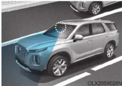
natural_image
Exterior view of a modern SUV on a road (no visible text or symbols)The Lane Keeping Assist (LKA) system helps detect lane markers on the road with a front view camera at the front windshield, and assists the driver's steering to help keep the vehicle between lanes.
When the system detects the vehicle straying from its lane, it alerts the driver with a visual and audible warning, while applying a counter-steering torque, trying to help prevent the vehicle from moving out of its lane.
WARNING
The Lane Keeping Assist (LKA) system is not a substitute for safe driving practices, but a convenience function only. It is the responsibility of the driver to always be aware of the surroundings and steer the vehicle.
WARNING
Take the following precautions when using the Lane Keeping Assist (LKA) system:
- Do not turn the steering wheel suddenly when the steering wheel is being assisted by the system.
-
LKA system helps to prevent the driver from moving out of the lane unintentionally by assisting the driver's steering. However, the driver should not solely rely on the system but always pay attention on the steering wheel to stay in the lane.
-
The operation of the LKA system can be canceled or not work properly according to road condition and surroundings. Always be cautious when driving.
- Do not disassemble the LKA system camera temporarily to tint the window or attach any types of coatings and accessories. If you disassemble the camera and assemble it again, take your vehicle to an authorized HYUNDAI dealer and have the system checked for calibration.
-
When you replace the windshield glass, LKA system camera or related parts of the steering wheel, take your vehicle to an authorized HYUNDAI dealer and have the system checked for calibration.
-
The system helps detect lane lines and controls the steering wheel by a camera, therefore, if the lane lines are hard to detect, the system may not work properly.
Please refer to "Limitations of the System". - Do not remove or damage the related parts of LKA system.
- You may not hear a warning sound of LKA system if the audio volume is high.
- If any other warning sound such as seat belt warning chime is already generated, the Lane Keeping Assist (LKA) system warning may not sound.
- Do not place objects on the dashboard that reflects light such as mirrors, white paper, etc. This may prevent the LKA system from functioning properly.
• Always have your hands on the steering wheel while the LKA system is activated.
- The steering wheel is not continuously controlled so if the vehicle speed is at a higher speed when leaving a lane the vehicle may not be able to be controlled by the system. The driver must always follow the speed limit when using the system.
- If you attach objects to the steering wheel, the system may not assist steering or the hands off alarm may not work properly. When you tow a trailer, make sure that you turn off the LKA system.
- When you tow a trailer, make sure that you turn off the LKA system.
LKA System Operation
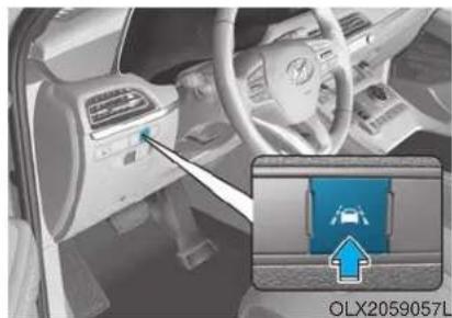
natural_image
Interior view of a car showing the dashboard and steering wheel, with an inset highlighting a blue 'OLX2059057L' component (no readable text or symbols)To activate/deactivate the LKA system:
With the ignition switch in the ON position, press the LKA system switch located on the instrument panel on the left hand side of the steering wheel. The indicator in the cluster display will initially illuminate white. This indicates the LKA system is in the READY but NOT ENABLED state.
If you press the LKA button again, the indicator on the cluster display will go off.
Note that the vehicle speed must be at least approximately 40 mph (64 km/h) to ENABLE the
LKA system. The indicator in the cluster will illuminate green.
The color of indicator will change depending on the condition of LKA system.
- White : Sensor does not detect lane markers or vehicle speed is under 40 mph (64 km/h).
- Green : Sensor detects lane markers and the system is able to control vehicle steering.
i Information
If the indicator (white) is activated from the previous ignition cycle, the system will turn ON without any additional control. If you press the LKA switch again, the indicator on the cluster goes off.
LKA system operation
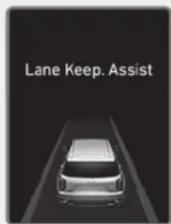
OLX2059058N
- To see the LKA system screen on the LCD display in the cluster, select Assist mode (For more details, refer to "LCD Display Modes" in chapter 3.
■ Lane marker undetected
■ Lane marker detected
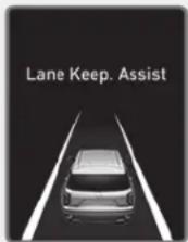
OLX2059058N/OLX2059059N
- If vehicle speed is over 40 mph (64 km/h) and the system detects lane markers, the color changes from gray to white.
- If your vehicle departs from the projected lane in front of you, the LKA system operates as follows:
■ Left lane marker
■ Right lane marker

OLX2059061N/OLX2059060N
-
A visual warning appears on the cluster LCD display. Either the left lane marker or the right lane marker in the cluster LCD display will blink depending on which direction the vehicle is veering. Also, the steering wheel will vibrate.
-
The LKA system will help control the vehicle's steering to prevent the vehicle from crossing the lane maker in below conditions.
-
Vehicle speed is over 40 mph (64 km/h)
- When driving, the vehicle is located between both lanes normally.
- The steering wheel is not turned suddenly.
When lanes are detected and all the conditions to activate the LKA system are satisfied, a LKA system indicator light (Will change from white to green. This indicates that the LKA system is in the ENABLED state and the steering wheel will be controlled.
Warning Light and Message
Keep hands on steering wheel
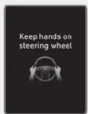
OLX2059062N
If the driver takes their hands off the steering wheel for several seconds while the LKA system is activated, the system will warn the driver.
i Information
If the steering wheel is held very lightly, the message may still appear because the LKA system may not recognize that the driver has their hands on the wheel.
WARNING
The warning message may appear late according to road conditions. Therefore, always have your hands on the steering wheel while driving.
WARNING
• The LKA system is a supplemental system only. It is the responsibility of the driver to safely steer the vehicle and to maintain it in its lane.
- Turn off the LKA system and drive without using the system in the following situations:
- In bad weather
- In bad road conditions
- When the steering wheel needs to be controlled by the driver frequently.
i Information
• Even though the steering is assisted by the system, the driver can still steer to control the steering wheel.
• The steering wheel may feel heavier when the steering wheel is assisted by the system than when it is not.
Check Lane Keeping Assist (LKA) system
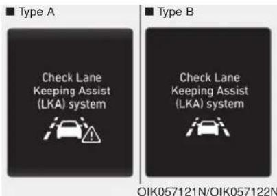
If there is a problem with the system a message will appear for a few seconds. If the problem continues the LKA system failure indicator will illuminate.
LKA system indicator
The LKA system indicator (yellow) will illuminate if the LKA system is not working properly. Have your vehicle checked by an authorized HYUNDAI dealer.
When there is a problem with the system do one of the following:
- Turn the system on after turning the engine off and on again.
- Check if the ignition switch is in the ON position.
- Check if the system is affected by the weather. (ex: fog, heavy rain, etc.)
- Check if there is foreign matter on the camera lens.
If the problem is not solved, have your vehicle checked by an authorized HYUNDAI dealer.
The LKA system will not be in the ENABLED state and/or the steering wheel will not be assisted when:
- The turn signal is turned on before changing a lane. If you change lanes without the turn signal on, the steering wheel might be controlled.
- The vehicle is not driven in the middle of the lane when the system is turned on or right after changing a lane.
- ESC (Electronic Stability Control) or VSM (Vehicle Stability Management) is activated.
- The vehicle is driven on a sharp curve.
- Vehicle speed is below 35 mph (56 km/h) and over 110 mph (177 km/h).
- The vehicle makes sharp lane changes.
• The vehicle brakes suddenly.
• The lane is very wide or narrow. - There are more than two lane lines on the road. (e.g.construction area)
-
Radius of a curve is too small.
-
The vehicle is driven on a steep incline.
- The steering wheel is turned suddenly.
- The system may not operate for 15 seconds after the engine is started or the camera is initialized.
Limitations of the System
The LKA system may operate prematurely even if the vehicle does not depart from the intended lane, OR, the LKA system may not warn you if the vehicle leaves the intended lane under the following circumstances:
When the lane and road conditions are poor
- It is difficult to distinguish the lane marker from the road because the lane marker is covered with dust or sand.
- It is difficult to distinguish the color of the lane marker from the road.
-
There are markings on the road surface that look like a lane marker that is inadvertently being detected by the camera.
-
The lane marker is indistinct or damaged.
- The lane marker is merged or divided (e.g. tollgate).
- The lane number increases or decreases or the lane marker are crossing complicatedly.
- There are more than two lane markers on the road in front of you.
- The lane marker is very thick or thin.
• The lane is very wide or narrow. - The lane marker ahead is not visible due to rain, snow, water on the road, damaged or stained road surface, or other factors.
- The shadow is on the lane marker by a median strip, trees, guardrail, noise barriers, etc.
- The lane markers are complicated or a structure substitutes for the lines such as a construction area.
- There are crosswalk signs or other symbols on the road.
- The lane marker in a tunnel is stained with oil, etc.
- The lane suddenly disappears such as at the intersection.
When external condition is intervened
- The brightness outside changes suddenly such as when entering or exiting a tunnel, or when passing under a bridge.
- The brightness outside is too low such as when the headlamps are not on at night or the vehicle is going through a tunnel.
- There is a boundary structure in the roadway such as a concrete barrier, guardrail and reflector post that is inadvertently being detected by the camera.
- When light coming from a street light or an oncoming vehicle is reflected on a wet road surface such as a puddle in the road.
- The field of view in front is obstructed by sun glare.
-
There is not enough distance between you and the vehicle in front to be able to detect the lane marker or the vehicle ahead is driving on the lane marker.
-
Driving on a steep grade, over a hill, or when driving on a curved road.
- The adverse road conditions cause excessive vehicle vibrations while driving.
- The surrounding of the inside rear view mirror temperature is high due to direct sunlight, etc.
When front visibility is poor
- The windshield or the camera lens is blocked with dirt or debris.
- The windshield glass is fogged up; a clear view of the road is obstructed.
- Placing objects on the dashboard, etc.
- The sensor cannot detect the lane because of fog, heavy rain or snow.
LKA System Function Change
The driver can change LKA to Lane Departure Warning from the LCD display. Go to the 'User Settings → Driver Assistance → Lane Safety → Lane Keeping Assist (LKA)/Lane Departure Warning (LDW)/Off'.
The system is automatically set to Lane Keeping Assist(LKA) if a function is not selected.
- Lane Keeping Assist
Lane Keeping Assist guides the driver to help keep the vehicle within the lanes. It rarely controls the steering wheel, when the vehicle drives well inside the lanes. However, it starts to control the steering wheel, when the vehicle is about to deviate out of the lane.
- Lane Departure Warning
Lane Departure Warning alerts the driver with a visual warning and a warning alarm when the system detects the vehicle departing the lane. The steering wheel will not be controlled.
- Off
If you select 'off', the LKA system is deactivated.
DRIVER ATTENTION WARNING (DAW) SYSTEM (IF EQUIPPED)
The Driver Attention Warning (DAW) system is designed as a safety feature to help reduce drowsy or inattentive driving. The DAW displays a bar graph that is intended to represent the driver's attention and fatigue level while driving.
System Setting and Operation
System setting
The Driver Attention Warning can be activated from the User Settings menu in the cluster LCD display by following the procedure below.
- Set the ignition switch to the ON position.
- Select 'User Settings → Driver Assistance → Driver Attention Warning' in the cluster LCD display.
The system stops operation when the setting is deactivated. However, if the engine is turned off then on again, the system maintains the previous state.
Driver's attention level
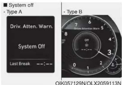
■ Attentive driving
- Type A
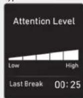
OIK057130N/OLX2059114N
■ Inattentive driving - Type A
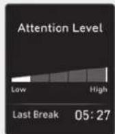
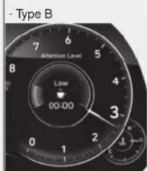
OIK057131N/OLX2059115N
- The driver can monitor his/her driving conditions on the cluster LCD display.
The DAW screen will appear when you select the Assist mode tab (A) on the LCD display if the system is activated. For more details, refer to "LCD Display Modes" in chapter 3.
- The driver's attention level is displayed on the scale of 1 to 5. The lower the number is, the more inattentive the driver is.
- The level decreases when the driver does not take a break for a certain period of time.
- The level increases when the driver attentively drives for a certain period of time.
- When the driver turns on the system while driving, it displays 'Last Break time' and level.
Take a break
OIK057132L
- The "Consider taking a break" message appears on the cluster LCD display and a warning sounds to suggest that the driver take a break, when the driver's attention level is below 1.
- The Driver Attention Warning (DAW) system will not suggest a break, when the total driving time is shorter than 10 minutes.
CAUTION
If any other warning sound such as seat belt warning chime is already generated, the Driver Attention Warning (DAW) system warning may not sound.
Resetting the System
- The last break time is set to 00:00 and the driver's attention level is set to 5 (very attentive) when the driver resets the Driver Attention Warning (DAW) system.
-
The Driver Attention Warning (DAW) system resets in the following situations.
-
The engine is turned OFF.
- The driver unfastens the seat belt and then opens the driver's door.
- The vehicle is stopped for more than 10 minutes.
- The Driver Attention Warning (DAW) system operates again, when the driver restarts driving.
System Standby
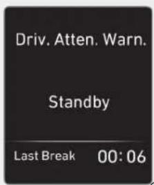
OIK057133N
The Driver Attention Warning (DAW) system enters the ready status and displays the 'Standby' screen in the following situations.
- The system is unable to collect data to monitor the driver's driving conditions.
- Driving speed remains under 40 mph (64 km/h) or over 110 mph (180 km/h).
System Malfunction
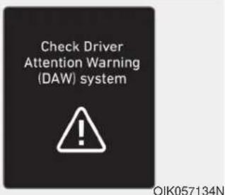
Check Driver Attention Warning (DAW) system
When the warning message appears, the system is not working properly. In this case, have the vehicle inspected by an authorized HYUNDAI dealer.
WARNING
- The Driver Attention Warning system is not a substitute for safe driving practices, but a convenience function only. It is the responsibility of the driver to always drive cautiously to prevent unexpected and sudden situations from occurring. Pay attention to the road conditions at all times.
- The driver who feels fatigued should take a break, even though there is no break suggestion by the Driver Attention Warning system.
i Information
The system may suggest a break according to the driver's driving pattern or habits even if the driver doesn't feel fatigue.
NOTICE
The Driver Attention Warning system utilizes the camera sensor on the front windshield for its operation. To keep the camera sensor in the best condition, you should observe the followings:
- NEVER install any accessories or stickers on the front windshield, or tint the front windshield.
- NEVER place any reflective objects (i.e. white paper, mirror) over the crash pad. Any light reflection may prevent the system from functioning properly.
- Pay extreme caution to keep the camera sensor dry.
- Never disassemble the camera assembly, or apply any impact on the camera assembly.
If the sensor is forcibly moved out of proper alignment, the system may not operate correctly. Take your vehicle to an authorized HYUNDAI dealer and have the system checked for calibration.
CAUTION
The Driver Attention Warning (DAW) system may not provide alerts in the following situations:
- The lane detection performance is limited. (For more details, refer to "Lane Keeping Assist (LKA) system" in this chapter.)
- The vehicle is erratically driven or is abruptly turned for obstacle avoidance (e.g. construction area, other vehicles, fallen objects, bumpy road).
- Forward drivability of the vehicle is severely undermined (possibly due to wide variation in tire pressures, uneven tire wear-out, toe-in/toe-out alignment).
-
The vehicle drives on a curvy road.
-
The vehicle drives on a bumpy road.
- The vehicle drives through a windy area.
- The vehicle is controlled by the following driving assist systems:
- Forward Collision-avoidance Assist (FCA)
- Smart Cruise Control (SCC)
- Lane Following Assist (LFA)
- Lane Keeping Assist (LKA)
- Blind-Spot Collision-Avoidance Assist (BCA)
- Highway Driving Assist (HDA)
CAUTION
Playing the vehicle audio system at high volume may prevent occupants from hearing the Driver Attention Warning (DAW) system warning sounds.
HIGHWAY DRIVING ASSIST (HDA) SYSTEM (IF EQUIPPED)
The Highway Driving Assist (HDA) system helps keep the vehicle between lanes, maintain a distance with the vehicle ahead, and automatically adjusts the vehicle speed to the speed limit while driving on the highway.
WARNING
- The Highway Driving Assist (HDA) system is not a substitute for safe driving practices, but a convenience function. It is the responsibility of the driver to always be aware of the surroundings and drive safely.
- The Highway Driving Assist (HDA) system relies entirely on the road information provided by the navigation system. It is the responsibility of the driver to follow traffic laws and avoid accidents.
- For your safety, please read the owner's manual before using the system.
i Information
- The Highway Driving Assist (HDA) system is available only on controlled access road of certain highways.
*Controlled access road indicates roads with limited entrances and exits that allow uninterrupted high speed traffic flow. Only passenger cars and motorcycles are allowed on controlled access roads.
Available highway (Controlled access road)
| USA | Interstate Highway |
| Canada | Select Provincial and Territorial Highways |
• Additional highways may be expanded by navigation updates.
System Setting and Operation
System setting
- With the Engine Start/Stop button in the ON or START position, the Highway Driving Assist can be activated by selecting 'All menus → Setup → Vehicle → Driver Assistance → Highway Driving Assist' from the Settings menu in the infotainment system screen. Deselect the setting to turn off the system.
- If the engine is turned off then on again, the system maintains the last setting.
Operating conditions
Select 'Highway Driving Assist' from the Settings menu in the infotainment system screen and satisfy the following conditions for the system to operate.
- Driving on the highway main line
• Smart Cruise Control is operating
- If the Smart Cruise Control is in the READY state the Highway Driving Assist will be in the READY state. The HDA cator on the cluster will illuminate white.
• Vehicle speed is under 95 mph (153 km/h)
If all the mentioned conditions are satisfied, the system is ENABLED and the -Do or on the cluster will illuminate green.
Steering wheel control
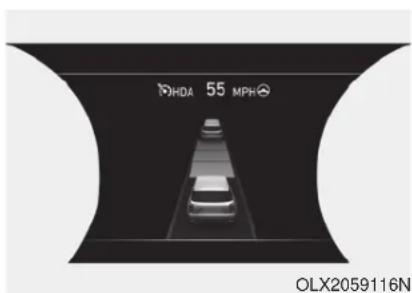
Steering control
If the vehicle detects both lane markers (lane color white), the indicator light will change from white to green. This indicates that the steering wheel is being controlled.
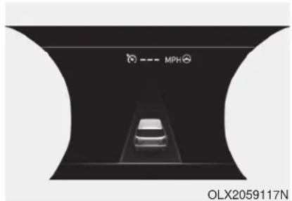
natural_image
Top-down view of a car on a road with 'MPH' branding and 'OLX2059117N' text overlay (no other signage or symbols)Temporary deactivation
The indicator light changes from green to white when the steering wheel control is temporarily deactivated. Even if the steering wheel is not controlled, the distance between the vehicle ahead will be maintained.
Speed setting
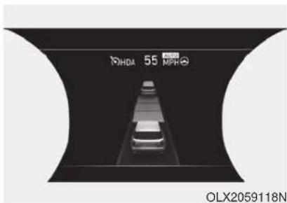
Automatic speed setting mode
The system enters the automatic speed setting mode when:
- The operating conditions are satisfied
- Mo HBA or will illuminate green
- The Smart Cruise Control set speed and the highway speed limit matches
If the system changes to the automatic speed mode, the AUTCpol will turn green and a chime will sound.
When the highway speed limit changes, the set speed automatically changes to the changed speed limit.
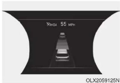
Manual speed setting mode
If the speed is set manually using the RES+ or SET- toggle switch on the steering wheel, the set speed on the cluster will turn white and the 'AUTO' symbol will disappear.
Warning Message
Hands-off warning
Keep hands on steering wheel
If the driver takes their hands off the steering wheel for several seconds while the HDA system is activated, the system will warn the driver.
i Information
If the steering wheel is held with a light grip, the message may appear because the HDA system may not recognize that the driver has their hands on the steering wheel.
WARNING
The warning message may appear late according to road conditions. Therefore, always have your hands on the steering wheel while driving.
![Highway Driving Assist [HDA] system canceled HDA OHI058296L](/content/2026/05/810583/images/e736bb271e01e366f04fc645d4f081e7de55dca1f779832b55675b65ae1fb556.jpg)
Highway Driving Assist (HDA) system canceled
If the driver still does not have their hands on the steering wheel after the message "Keep hands on steering wheel", the HDA system will be canceled. However, if the Smart Cruise Control is reactivated manually by the driver, the Highway Driving Assist System will reactivate.
To activate Smart Cruise control, refer to "Smart Cruise Control with Stop and Go" in chapter 5.
The HDA system will not be in the ENABLED state and/or the steering wheel will not be assisted when:
- The turn signal is turned on before changing a lane. If you change lanes without the turn signal on, the steering wheel might be controlled.
- The vehicle is not driven in the middle of the lane when the system is turned on or right after changing a lane.
- ESC (Electronic Stability Control) or VSM (Vehicle Stability Management) is activated.
- The vehicle is driven on a sharp curve.
- Vehicle speed is over 95 mph (153 km/h).
- The vehicle makes sharp lane changes.
• The vehicle brakes suddenly. - Only one lane marker is detected.
- The lane is very wide or narrow.
-
There are more than two lane markers on the road (e.g.construction area).
-
Radius of a curve is too small.
- The vehicle is driven on a steep incline.
- The steering wheel is turned suddenly.
System malfunction
Check Highway Driving Assist (HDA) system
If there is a problem with the system, a message will appear for a few seconds. If the problem continues, have the vehicle inspected by an authorized HYUNDAI dealer.
i Information
• Highway Driving Assist is limited in other countries.
• Highway Driving Assist only operates based on the speed limits of the highway but it does not work with the speed cameras.
- The time gap could occur between the navigation speed warning and system operation.
- The system is not designed to work on highways other than mentioned as a controlled access road. The system automatically cancels when you leave the highway.
- If there is a problem with Highway Driving Assist, the system cannot be activated in the infotainment system screen.
- If your vehicle is 1640 ft. (500 m) ahead and behind of an open tollgate, the system is automatically canceled. Also, it is converted to Smart Cruise Control automatically with a pop-up message on the navigation.
- In the automatic speed setting mode, the vehicle automatically accelerates or decelerates when the highway speed limit changes.
- If your vehicle speed exceeds 95 mph (153 km/h), Highway Driving Assist is automatically canceled. Also, it is converted to Smart Cruise Control automatically with a pop-up message on the navigation.
- If you enter a rest area on the highway or a IC/JC (intersection/junction) without a destination set, the system is canceled later than when the vehicle actually leaves the highway.
CAUTION
The Highway Driving Assist system may not function properly in the following situations:
- The navigation is not working properly.
• The navigation is not updated. - The real-time GPS or map information provided has errors.
- The navigation is overloaded by performing functions such as route search, video playback, voice recognition, etc. are performing simultaneously.
• GPS signals are blocked in areas such as a tunnel. - The driver goes off course or the route to the destination is changed or canceled by resetting the navigation.
- The vehicle enters a service station or rest area
-
Android Auto or Car Play is operating.
-
The navigation cannot detect the current vehicle position (ex: elevated roads including overpass adjacent to general roads or nearby roads exist in a parallel way).
- The navigation is being updated while driving.
- The navigation is being reset while driving.
- The road is slippery due to bad weather such as rain or snow.
i Information
- For information's on vehicle to vehicle distance control and the front radar, refer to "Smart Cruise Control (Stop & Go)" in this chapter.
- For information's on steering control and distance control and the front camera, refer to "Lane Following Assist (LFA)" in this chapter.
i Information
This device complies with Part 15 of the FCC rules.
Operation is subject to the following three conditions:
- This device may not cause harmful interference, and
- This device must accept any interference received, including interference that may cause undesired operation.
- Changes or modifications not expressly approved by the party responsible for compliance could void the user's authority to operate the device.
i Information
Radio frequency radiation exposure information:
This equipment complies with FCC radiation exposure limits set forth for an uncontrolled environment.
This equipment should be installed and operated with minimum distance of 8 in. (20 cm) between the radiator (antenna) and your body.
This transmitter must not be co-located or operating in conjunction with any other antenna or transmitter.
SMART CRUISE CONTROL WITH STOP & GO SYSTEM (IF EQUIPPED)
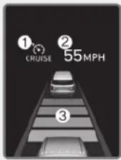
OLX2059049N
① Cruise indicator
② Set speed
③ Vehicle-to-vehicle distance
To see the SCC screen on the LCD display in the cluster, select Assist mode (A) For more details, refer to "LCD Display Modes" in chapter 3.
The Smart Cruise Control system allows you to program the vehicle to help maintain the desired speed and minimum distance between the vehicle ahead.
The Smart Cruise Control system will automatically adjust your vehicle speed to maintain your programmed speed and following distance without requiring you to depress the accelerator or brake pedals.
WARNING
For your safety, please read the owner's manual before using the Smart Cruise Control system.
WARNING
The Smart Cruise Control system is not a substitute for safe driving practices, but a convenience function only. It is the responsibility of the driver to always check the speed and distance to the vehicle ahead.
WARNING
Take the following precautions :
• Always set the vehicle speed under the speed limit.
- If the Smart Cruise Control is left on, (cruise indicator light in the instrument cluster is illuminated) the Smart Cruise Control can be activated unintentionally. Keep the Smart Cruise Control system off (cruise indicator light OFF) when the Smart Cruise Control is not in use, to avoid inadvertently setting a speed.
- Use the Smart Cruise Control system only when traveling on open highways in good weather.
- Do not use the Smart Cruise Control when it may not be safe to keep the vehicle at a constant speed.
- Do not use when:
- Driving in heavy traffic or when traffic conditions make it difficult to drive at a constant speed
- Driving on rainy, icy, or snow-covered roads
- Driving on a steep downhill or uphill
- Driving in windy areas
- Driving in parking lots
- Driving near crash barriers
- Driving on a sharp curve
- Driving with limited view (possibly due to bad weather, such as fog, snow, rain or sandstorm)
- The vehicle's sensing ability decreases due to vehicle modification, resulting in a level difference of the vehicle's front and rear
- Unexpected situations may lead to possible accidents. Pay attention continuously to road conditions and driving even when the smart cruise control system is being operated.
Smart Cruise Control Switch
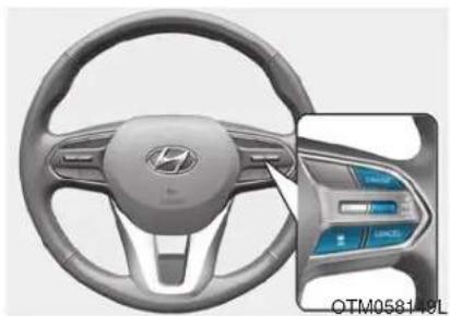
natural_image
Interior view of a car steering wheel and dashboard (no visible text or symbols)CRUISE: Turns cruise control sys- tem on or off.
RES+: Resumes or increases cruise control speed.
SET-: Sets or decreases cruise control speed.
: Sets vehicle-to-vehicle distance.
CANCEL: Cancels cruise control operation.
Adjusting the Sensitivity of Smart Cruise Control
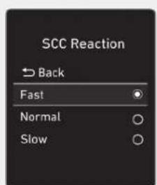
OIK057097N
The sensitivity of vehicle speed when following the front vehicle to maintain the set distance can be adjusted. Go to the 'User Settings → Driver Assistance → SCC Reaction → Fast/Normal/Slow' on the LCD display. You may select one of the three stages you prefer.
- Fast:
Vehicle speed following the front vehicle to maintain the set distance is faster than normal speed.
- Normal:
Vehicle speed following the front vehicle to maintain the set distance is normal.
- Slow:
Vehicle speed following the front vehicle to maintain the set distance is slower than normal speed.
i Information
The last selected speed sensitivity of the smart cruise control is remained in the system.
To Convert to Cruise Control Mode
The driver may choose to switch to use the conventional Cruise Control mode (speed only control function) by following these steps:
- Push the CRUISE button on the steering wheel to turn the system on. The cruise (F)CRUISE cator will illuminate.
- Push and hold the Vehicle-to-Vehicle Distance button for more than 2 seconds.
- Choose between "Smart Cruise Control" and "Cruise Control".
When the system is canceled using the CRUISE button or the CRUISE button is used after the engine is turned on, the Smart Cruise Control mode will turn on.
WARNING
When using the conventional Cruise Control mode, you must manually adjust the distance to other vehicles by depressing the brake pedal. The system does not automatically adjust the distance to vehicles in front of you.
Smart Cruise Control Speed
To set Smart Cruise Control speed
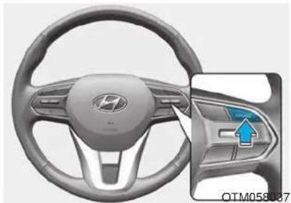
natural_image
Interior view of a car dashboard and steering wheel (no visible text or symbols)-
Push the CRUISE button on the steering wheel to turn the system on. The cruise indicator will illuminate.
-
Accelerate to the desired speed. The Smart Cruise Control speed can be set as follows:
- 5 – 100 mph (10 - 160 km/h) : when there is no vehicle in front
- 0 - 100 mph (0 - 160 km/h) : when there is a vehicle in front
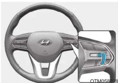
natural_image
Interior view of a car dashboard and steering wheel (no visible text or symbols)- Push the toggle switch down (SET-). The Set Speed and Vehicle-to-Vehicle Distance on the LCD display will illuminate.
- Release the accelerator pedal. The desired speed will automatically be maintained.
If there is a vehicle in front of you, the speed may decrease to maintain the distance to the vehicle ahead.
On a steep grade, the vehicle may slow down or speed up slightly while going uphill or downhill.
i Information
- Vehicle speed may decrease on an upward slope and increase on a downward slope.
- When you are setting the cruise control speed, with a vehicle in front and your vehicle speed is between 0 \~ 20 mph (0 \~ 30 km/h), the speed will set to 20 mph (30 km/h).
- Vehicle speed may decrease on an upward slope and increase on a downward slope.
- When you are setting the cruise control speed, with a vehicle in front and your vehicle speed is between 0 \~ 20 mph (0 \~ 30 km/h), the speed will set to 20 mph (30 km/h).
To increase Smart Cruise Control set speed
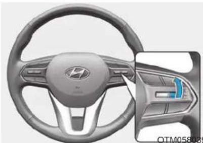
natural_image
Interior view of a car steering wheel and dashboard (no visible text or symbols)CAUTION
Check the traffic and driving conditions before using the toggle switch. Driving speed may sharply increase, when you push up and hold the toggle switch.
Follow either of these procedures:
- Push the toggle switch up (RES+), and release it immediately. The cruising speed will increase by 1 mph (1 km/h) each time you move the toggle switch up in this manner.
- Push the toggle switch up (RES+), and hold it. Your vehicle set speed will increase by 5 mph (10 km/h). Release the toggle switch at the speed you want.
You can set the speed to 100 mph (160 km/h).
To decrease the Smart Cruise Control set speed
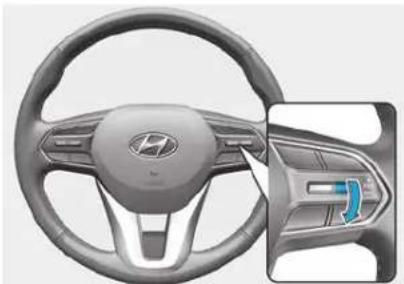
natural_image
Interior view of a car steering wheel and dashboard (no visible text or symbols)Follow either of these procedures:
- Push the toggle switch down (SET-), and release it immediately. The cruising speed will decrease by 1 mph (1 km/h) each time you move the toggle switch down in this manner.
- Push the toggle switch down (SET-), and hold it. Your vehicle set speed will decrease by 5 mph (10 km/h). Release the toggle switch at the speed you want.
- You can set the speed to 20 mph (30 km/h).
To temporarily accelerate with the Smart Cruise Control on
If you want to speed up temporarily when the Smart Cruise Control is on, depress the accelerator pedal. Increased speed will not interfere with Smart Cruise Control operation or change the set speed.
To return to the set speed, take your foot off the accelerator pedal.
If you push the toggle switch down (SET-) at increased speed, the cruising speed will be set again corresponding to the pedal position.

CAUTION
Be careful when accelerating temporarily, because the speed is not controlled automatically at this time even if there is a vehicle in front of you.
Smart Cruise Control set speed will be temporarily canceled when:
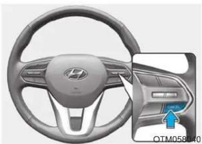
natural_image
Interior view of a car dashboard and steering wheel, showing the steering wheel and dashboard (no text or symbols visible)Canceled manually
• Depressing the brake pedal.
- Pushing the CANCEL button located on the steering wheel.
The Smart Cruise Control turns off temporarily when the Set Speed and Vehicle-to-Vehicle Distance indicator on the cluster LCD display turns off.
The cruise indicator is illuminated continuously.
Canceled automatically
• The driver's door is opened.
- The vehicle is shifted to N (Neutral), R (Reverse) or P (Park).
• The EPB (Electronic Parking Brake) is applied.
• The vehicle speed is over 110 mph (170 km/h).
• The vehicle stops on a steep incline.
• The ESC (Electronic Stability Control), TCS (Traction Control System) or ABS is operating.
- The ESC is turned off. - The sensor or the cover is dirty or blocked with foreign matter.
- The vehicle is stopped for a certain period of time.
- The vehicle stops and goes repeatedly for a long period of time.
- The accelerator pedal is continuously depressed for a long period of time.
• The engine stops or the engine performance is abnormal.
• Engine rpm is in the red zone.
- The driver starts driving by pushing the toggle switch up (RES+)/down (SET-) or depressing the accelerator pedal, after the vehicle is stopped by the Smart Cruise Control system with no other vehicle ahead.
- The driver starts driving by pushing the toggle switch up (RES+)/down (SET-) or depressing the accelerator pedal, after stopping the vehicle with a vehicle stopped far away in front.
- The Forward Collision-Avoidance Assist (FCA) is activated.
- The engine is stopped by ISG (Idle Stop & Go) (if equipped).
Each of these actions will cancel the Smart Cruise Control operation. The Set Speed and Vehicle-to-Vehicle Distance on the cluster LCD display will go off.
In a condition the Smart Cruise Control is cancelled automatically, the Smart Cruise Control will not resume even though the RES+ or SET- toggle switch is pushed.
Also, if the Smart Cruise Control is canceled automatically while the vehicle is at a standstill, EPB (Electronic Parking Brake) will be applied.
i Information
If the Smart Cruise Control is canceled during a situation that is not described above, have the system checked by an authorized HYUNDAI dealer.
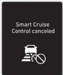
OIK057096N
Smart Cruise Control canceled If the system is canceled, the warning chime will sound and a message will appear for a few seconds.
You must adjust the vehicle speed by depressing the accelerator or brake pedal according to the road and driving conditions.
Always check the road conditions. Do not rely on the warning chime.
To resume Smart Cruise Control set speed
If any method other than the cruise toggle switch was used to cancel cruising speed and the system is still activated, the cruising speed will automatically resume when you push the toggle switch up (RES+) or down (SET-).
If you push the toggle switch up (RES+), the speed will resume to the recently set speed. However, if vehicle speed drops below 20 mph (30 km/h), it will resume when there is a vehicle in front of your vehicle.
WARNING
• To avoid collisions, always be aware of the selected speed and vehicle to vehicle distance settings when activating your smart cruise control system.
• Always maintain sufficient braking distance and decelerate your vehicle by applying the brakes if necessary.
To turn Cruise Control off
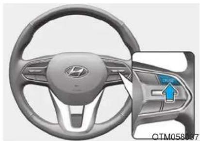
natural_image
Interior view of a car dashboard and steering wheel, showing the steering wheel and dashboard (no text or symbols visible)- Push the CRUISE button (the cruise indicator light will go off). If you wish not to use the cruise control system, always turn the system off by pushing the CRUISE button.
Smart Cruise Control Vehicle-to-Vehicle Distance
To set Vehicle-to-Vehicle Distance
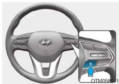
natural_image
Interior view of a car dashboard and steering wheel (no visible text or symbols)When the Smart Cruise Control system is ON, you can set and maintain the distance from the vehicle ahead of you without pressing the accelerator or brake pedal.
Each time the button is pressed, the vehicle to vehicle distance changes as follows:
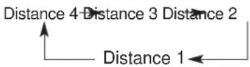
For example, if you drive at 56 mph (90 km/h), the distance is maintained as follows:
Distance 4 - approximately 172 feet
Distance 3 - approximately 130 feet
Distance 2 - approximately 106 feet
Distance 1 - approximately 82 feet
i Information
The distance is set to the last set distance when the system is used for the first time after starting the engine.
When the lane ahead is clear:
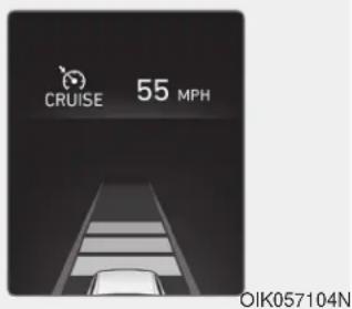
The vehicle speed will maintain the set speed.
When there is a vehicle ahead of you in your lane:
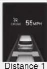
OLX2059078N/OLX2059053N/OLX2059052N/OLX2059051N
- Your vehicle speed will slow down or speed up to maintain the selected distance.
- If the vehicle ahead speeds up, your vehicle will travel at a steady cruising speed after accelerating to the set speed.
- If distance from the front vehicle has changed due to accelerating or decelerating of the front vehicle, the distance on the cluster LCD display may change.
WARNING
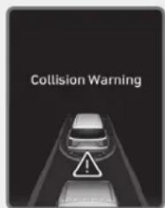
OLX2059026N
When using the Smart Cruise Control system:
- The warning message appears and warning chime sounds if the vehicle is unable to maintain the selected distance from the vehicle ahead.
- If the warning message appears and warning chime sounds, depress the brake pedal or use the steering wheel toggle switch to actively adjust the vehicle speed, and the distance to the vehicle ahead.
• Even if the warning message does not appear and warning chime does not sound, always pay attention to the driving conditions to prevent dangerous situations from occurring.
- Playing the vehicle audio system at high volume may prevent occupants from hearing the system warning sounds.
CAUTION
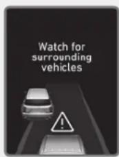
OLX2059054N
If the vehicle ahead (vehicle speed: less than 20 mph (30 km/h)) moves to the next lane, the warning chime will sound and a message "Watch for surrounding vehicles" will appear. Adjust your vehicle speed for vehicles or objects that can suddenly appear in front of you by depressing the brake pedal. Always pay attention to the road condition ahead.
In traffic situation
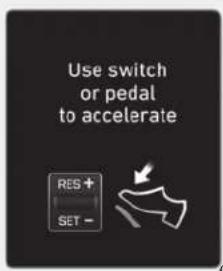
OIK057107L
Use switch or pedal to accelerate
- In traffic, your vehicle will stop if the vehicle ahead of you stops. Also, if the vehicle ahead of you starts moving, your vehicle will start as well. However, if the vehicle stops for more than 3 seconds, you must depress the accelerator pedal or push up the toggle switch (RES+) or push down the toggle switch (SET-) to start driving.
- If you push the smart cruise control toggle switch (RES+ or SET-) while Auto Hold and smart cruise control is operating the Auto Hold will be released regardless of accelerator pedal operation and the vehicle will start to move. The AUTO HOLD indicator changes from green to white.
Sensor to Detect Distance to the Vehicle Ahead
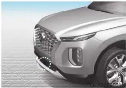
natural_image
Front view of a silver SUV with visible headlights and grille, parked on paved ground (no text or symbols)The Smart Cruise Control uses a sensor to detect distance to the vehicle ahead.
If the sensor is covered with dirt or other foreign matter, the vehicle to vehicle distance control may not operate correctly.
Always keep the sensor clean.
Warning message
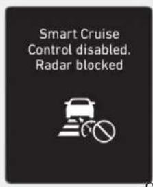
OTM058061L
Smart Cruise Control disabled. Radar blocked
When the sensor lens cover is blocked with dirt, snow, or debris, the Smart Cruise Control system operation may stop temporarily. If this occurs, a warning message will appear on the cluster LCD display. Remove any dirt, snow, or debris and clean the radar sensor lens cover before operating the Smart Cruise Control system. The Smart Cruise Control system may not properly activate, if the radar is totally contaminated, or if any substance is not detected after turning on the engine (e.g. in an open terrain).
i Information
For the SCC operation is temporarily stopped if the radar is blocked, but you wish to use conventional cruise control mode (speed only control function), you must convert to the cruise control mode (refer to "To convert to Cruise Control mode" in the following page).
CAUTION
- Do not apply license plate frame or foreign objects such as a bumper sticker or a bumper guard near the radar sensor. Doing so may adversely affect the sensing performance of the radar.
• Always keep the radar sensor and lens cover clean and free of dirt and debris. -
Use only a soft cloth to wash the vehicle. Do not spray pressurized water directly on the sensor or sensor cover.
-
Be careful not to apply unnecessary force on the radar sensor or sensor cover. If the sensor is forcibly moved out of proper alignment, the Smart Cruise Control system may not operate correctly. In this case, a warning message may not be displayed. Have the vehicle inspected by an authorized HYUNDAI dealer.
- If the front bumper becomes damaged in the area around the radar sensor, the Smart Cruise Control System may not operate properly. Have the vehicle inspected by an authorized HYUNDAI dealer.
- Use only genuine HYUNDAI parts to repair or replace a damaged sensor or sensor cover. Do not apply paint to the sensor cover.
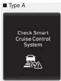
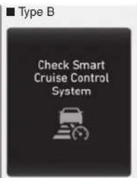
OIK057109L/OIK057110L
Check Smart Cruise Control System The message will appear when the vehicle to vehicle distance control system is not functioning normally.
Take your vehicle to an authorized HYUNDAI dealer and have the system checked.
Limitations of the System
The Smart Cruise Control system may have limits to its ability to detect distance to the vehicle ahead due to road and traffic conditions.
On curves
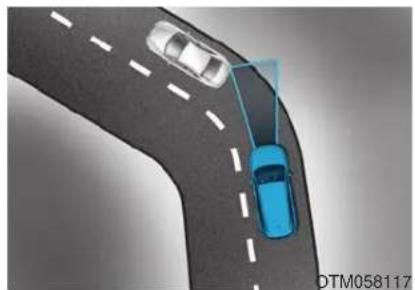
natural_image
Top-down view of two cars driving on a curved road, one blue and one white, with no visible text or symbols.- The Smart Cruise Control system may not detect a moving vehicle in your lane, and then your vehicle could accelerate to the set speed. Also, the vehicle speed will decrease when the vehicle ahead is recognized suddenly.
- Select the appropriate set speed on curves and apply the brakes or accelerator pedal if necessary.

natural_image
Top-down view of a road with two cars, one in blue and one in white, showing a collision or perspective (no text or symbols)Your vehicle speed can be reduced due to a vehicle in the adjacent lane. Apply the accelerator pedal and select the appropriate set speed. Check to be sure that the road conditions permit safe operation of the Smart Cruise Control.
On inclines
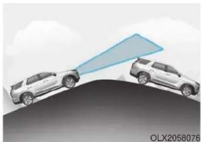
natural_image
Two white SUVs on a curved surface with a blue triangular arrow pointing toward them, under a cloudy sky (no text or symbols)- During uphill or downhill driving, the Smart Cruise Control system may not detect a moving vehicle in your lane, and cause your vehicle to accelerate to the set speed. Also, the vehicle speed will rapidly decrease when the vehicle ahead is recognized suddenly.
- Select the appropriate set speed on inclines and apply the brake or accelerator pedal if necessary.
Lane changing
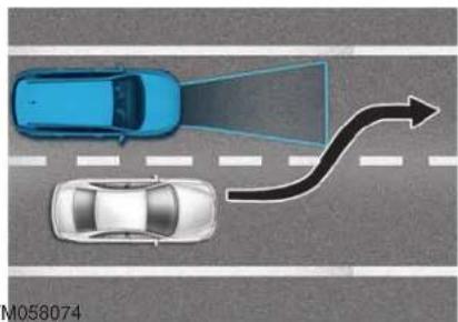
natural_image
Top-down diagram of a road with two cars, one emitting a light beam and the other with an arrow indicating direction (no text or symbols)• A vehicle which moves into your lane from an adjacent lane cannot be recognized by the sensor until it is in the sensor's detection range.
• The radar may not detect immediately when a vehicle cuts in suddenly. Always pay attention to the traffic, road and driving conditions.
- If a slower vehicle moves into your lane, your speed may decrease to maintain the distance to the vehicle ahead.
- If a faster vehicle which moves into your lane, your vehicle will accelerate to the set speed.
Detecting vehicles
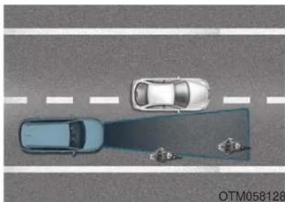
natural_image
Top-down view of a road with two cars and a parking lot, no visible text or symbolsSome vehicles in your lane cannot be recognized by the sensor:
- Narrow vehicles such as motorcycles or bicycles
- Vehicles offset to one side
- Slow-moving vehicles or sudden-decelerating vehicles
- Stopped vehicles
- Vehicles with small rear profile such as trailers with no loads
A vehicle ahead cannot be recognized correctly by the sensor if any of following occurs:
- When the vehicle is pointing upwards due to overloading in the luggage compartment
- While the steering wheel is operating
- When driving to one side of the lane
- When driving on narrow lanes or on curves
Apply the brake or accelerator pedal if necessary.
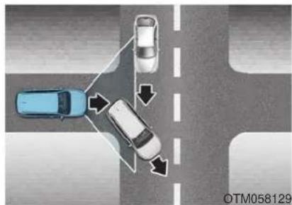
natural_image
Top-down view of a road intersection with cars and directional arrows indicating movement (no text or symbols)- Your vehicle may accelerate when a vehicle ahead of you disappears.
- When you are warned that the vehicle ahead of you is not detected, drive with caution.
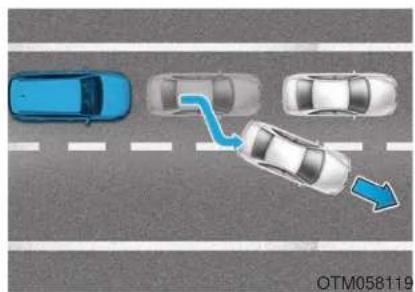
natural_image
Top-down view of a multi-lane road intersection with cars and a blue arrow indicating direction (no text or symbols)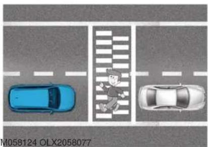
natural_image
Top-down view of a traffic intersection with two cars and a pedestrian crossing (no text or symbols)- When driving in stop-and-go traffic, and a vehicle in front of you merges out of the lane, the system may not immediately detect the new vehicle that is now in front of you. In this case, you must maintain a safe braking distance, and if necessary, depress the brake pedal to reduce your driving speed in order to maintain a safe distance.
• Always look out for pedestrians when your vehicle is maintaining a distance with the vehicle ahead.
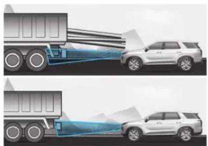
natural_image
Two illustrations of a white SUVs with blue light beams spraying from trucks, showing no text or symbols.• Always be cautious for vehicles with higher height or vehicles carrying loads that sticks out from the back of the vehicle.
WARNING
When using the Smart Cruise Control take the following precautions:
- If an emergency stop is necessary, you must apply the brakes. The smart cruise control system cannot guarantee the stop for every emergency situation.
- Keep a safe distance according to road conditions and vehicle speed. If the vehicle to vehicle distance is too close during a high-speed driving, a serious collision may result.
• Always maintain sufficient braking distance and decelerate your vehicle by applying the brakes if necessary. -
The Smart Cruise Control system cannot recognize a stopped vehicle, pedestrians or an oncoming vehicle. Always look ahead cautiously to prevent unexpected and sudden situations from occurring.
-
Vehicles moving in front of you with a frequent lane change may cause a delay in the system's reaction or may cause the system to react to a vehicle actually in an adjacent lane. Always drive cautiously to prevent unexpected and sudden situations from occurring.
• Always be aware of the selected speed and vehicle to vehicle distance. The driver should not solely rely on the system but always pay attention to driving conditions and control your vehicle speed. -
The Smart Cruise Control system may not recognize complex driving situations so always pay attention to driving conditions and control your vehicle speed.
-
The Smart Cruise Control system may recognize a pedestrian, bicycle, motorcycle, etc. as a vehicle. Always, look ahead cautiously to prevent unexpected and sudden situations from occurring.
i Information
The Smart Cruise Control system may not operate temporarily due to:
• Electrical interference
• A modified suspension
- Differences of tire abrasion or tire pressure
• Installing different type of tires
i Information
This device complies with Part 15 of the FCC rules.
Operation is subject to the following three conditions:
-
This device may not cause harmful interference, and
-
This device must accept any interference received, including interference that may cause undesired operation.
-
Changes or modifications not expressly approved by the party responsible for compliance could void the user's authority to operate the device.
i Information
Radio frequency radiation exposure information:
This equipment complies with FCC radiation exposure limits set forth for an uncontrolled environment.
This equipment should be installed and operated with minimum distance of 8 in. (20 cm) between the radiator (antenna) and your body.
This transmitter must not be co-located or operating in conjunction with any other antenna or transmitter.
LEADING VEHICLE DEPARTURE ALERT (IF EQUIPPED)
The Leading Vehicle Departure Alert system alerts the driver of the departure of the vehicle in front when the vehicle is stopped and the Smart Cruise Control (SCC) system is operating.
System Setting and Operation
System setting
The Leading Vehicle Departure Alert can be activated from the User Settings menu in the cluster LCD display by following the procedure below.
- Set the ignition switch to the ON position.
- Select 'User Settings →Driver Assistance →Leading Vehicle Departure Alert' in the cluster LCD display.
The system stops operation when the setting is deactivated. However, if the engine is turned off then on again, the system maintains the previous state.
System standby
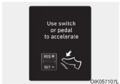
Use switch or pedal to accelerate
While the Smart Cruise Control (SCC) system is operating, your vehicle stops behind the vehicle in front when it stops. The message shown above is displayed on the cluster within 3 seconds after the stop and the system will be in the standby position.
System operation
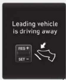
OTM058091L
Leading vehicle is driving away
If the driver does not take action for a certain period of time after the vehicle in front departs, the message shown above is displayed on the cluster.
The vehicle departs automatically if the accelerator pedal is depressed or RES + or SET - toggle switch is pushed up or down when there is a vehicle in front.
The Smart Cruise Control (SCC) system is deactivated if the accelerator pedal is depressed or RES + or SET - toggle switch is pushed up or down when there is no vehicle in front.
WARNING
Always check the front of the vehicle and road conditions before departure.
SPECIAL DRIVING CONDITIONS
Hazardous Driving Conditions
When hazardous driving elements are encountered such as water, snow, ice, mud and sand, take the below suggestions:
- Drive cautiously and keep a longer braking distance.
- Avoid abrupt braking or steering.
- When your vehicle is stuck in snow, mud, or sand, use second gear. Accelerate slowly to avoid unnecessary wheel spin.
- Put sand, rock salt, tire chains or other non-slip materials under the wheels to provide additional traction while the vehicle becomes stuck in ice, snow, or mud.
WARNING
Downshifting with an automatic transmission while driving on slippery surfaces can cause an accident. The sudden change in tire speed could cause the tires to skid. Be careful when down-shifting on slippery surfaces.
Rocking the Vehicle
If it is necessary to rock the vehicle to free it from snow, sand, or mud, first turn the steering wheel right and left to clear the area around your front wheels. Then, shift back and forth between R (Reverse) and a forward gear.
Try to avoid spinning the wheels, and do not race the engine.
To prevent transmission wear, wait until the wheels stop spinning before shifting gears. Release the accelerator pedal while shifting, and press lightly on the accelerator pedal while the transmission is in gear. Slowly spinning the wheels in forward and reverse directions causes a rocking motion that may free the vehicle.
WARNING
If the vehicle is stuck and excessive wheel spin occurs, the temperature in the tires can increase very quickly. If the tires become damaged, a tire blow out or tire explosion can occur. This condition is dangerous - you and others may be injured. Do not attempt this procedure if people or objects are anywhere near the vehicle.
If you attempt to free the vehicle, the vehicle can overheat quickly, possibly causing an engine compartment fire or other damage. Try to avoid spinning the wheels as much as possible to prevent overheating of either the tires or the engine. DO NOT allow the vehicle to spin the wheels above 35 mph (56 km/h).
i Information
The ESC system must be turned OFF before rocking the vehicle.
NOTICE
If you are still stuck after rocking the vehicle a few times, have the vehicle pulled out by a tow vehicle to avoid engine overheating, possible damage to the transmission, and tire damage. See "Towing" in chapter 6.
Smooth Cornering
Avoid braking or gear changing in corners, especially when roads are wet. Ideally, corners should always be taken under gentle acceleration.
Driving at Night
Night driving presents more hazards than driving in the daylight. Here are some important tips to remember:
- Slow down and keep more distance between you and other vehicles, as it may be more difficult to see at night, especially in areas where there may not be any street lights.
- Adjust your mirrors to reduce the glare from other driver's head-lamps.
- Keep your headlamps clean and properly aimed. Dirty or improperly aimed headlamps will make it much more difficult to see at night.
- Avoid staring directly at the head-lamps of oncoming vehicles. You could be temporarily blinded, and it will take several seconds for your eyes to readjust to the darkness.
Driving in the Rain
Rain and wet roads can make driving dangerous. Here are a few things to consider when driving in the rain or on slick pavement:
- Slow down and allow extra following distance. A heavy rainfall makes it harder to see and increases the distance needed to stop your vehicle.
- Turn OFF your Cruise Control.
- Replace your windshield wiper blades when they show signs of streaking or missing areas on the windshield.
- Tires should be properly maintained with at least 2/32nds of an inch of tread depth. If your tires do not have enough tread, making a quick stop on wet pavement can cause a skid and possibly lead to an accident. See "Tire replacement" in chapter 7.
-
Turn on your headlamps to make it easier for others to see you.
-
Driving too fast through large puddles can affect your brakes. If you must go through puddles, try to drive through them slowly.
- If you believe your brakes may be wet, apply them lightly while driving until normal braking operation returns.
Hydroplaning
If the road is wet enough and you are going fast enough, your vehicle may have little or no contact with the road surface and actually ride on the water. The best advice is SLOW DOWN when the road is wet.
The risk of hydroplaning increases as the depth of tire tread decreases, refer to "Tire replacement" in chapter 7.
Driving in Flooded Areas
Avoid driving through flooded areas unless you are sure the water is no higher than the bottom of the wheel hub. Drive through any water slowly. Allow adequate stopping distance because brake performance may be reduced.
After driving through water, dry the brakes by gently applying them several times while the vehicle is moving slowly.
Highway Driving
Tires
Adjust the tire inflation, as specified. Under-inflation may overheat or damage the tires.
Do not install worn-out or damaged tires, which may reduce traction or adversely affect vehicle handling. This could lead to sudden tire failure that may cause loss of vehicle control resulting in an accident.
i Information
Never over-inflate your tires above the maximum inflation pressure, as specified on your tires.
Fuel, engine coolant and engine oil
Driving at higher speeds on the highway consumes more fuel and is less efficient than driving at a slower, more moderate speed. Maintain a moderate speed in order to conserve fuel when driving on the highway.
Be sure to check both the engine coolant level and the engine oil before driving.
Drive belt
A loose or damaged drive belt may overheat the engine.
Reducing the Risk of a Rollover
Your multi-purpose passenger vehicle is defined as a Sports Utility Vehicle (SUV). SUV's have higher ground clearance and a narrower track to make them capable of performing in a wide variety of off-road applications. The specific design characteristics give them a higher center of gravity than ordinary vehicles making them more likely to roll over if you make abrupt turns. Utility vehicles have a significantly higher rollover rate than other types of vehicles. Due to this risk, driver and passengers are strongly recommended to buckle their seat belts. In a rollover crash, an unbelted person is significantly more likely to die than a person wearing a seat belt.
There are steps that a driver can make to reduce the risk of a rollover. If at all possible, avoid sharp turns or abrupt maneuvers, do not load your vehicle with heavy cargo on the roof, and never modify your vehicle in any way.
WARNING
Utility vehicles have a significantly higher rollover rate than other types of vehicles. To prevent rollovers or loss of control:
• Take corners at slower speeds than you would with a passenger vehicle.
- Avoid sharp turns and abrupt maneuvers.
- Do not modify your vehicle in any way that you would raise the center of gravity.
- Keep tires properly inflated.
- Do not carry heavy cargo on the roof.
WINTER DRIVING
The severe weather conditions of winter quickly wear out tires and cause other problems. To minimize winter driving problems, you should take the following suggestions:
Snow or Icy Conditions
You need to keep sufficient distance between your vehicle and the vehicle in front of you.
Apply the brakes gently. Speeding, rapid acceleration, sudden brake applications, and sharp turns are potentially very hazardous practices. During deceleration, use engine braking to the fullest extent. Sudden brake applications on snowy or icy roads may cause the vehicle to skid.
To drive your vehicle in deep snow, it may be necessary to use snow tires or to install tire chains on your tires.
Always carry emergency equipment. Some of the items you may want to carry include tire chains, tow straps or chains, a flashlight, emergency flares, sand, a shovel, jumper cables, a window scraper, gloves, ground cloth, coveralls, a blanket, etc.
Snow tires
WARNING
Snow tires should be equivalent in size and type to the vehicle's standard tires. Otherwise, the safety and handling of your vehicle may be adversely affected.
If you mount snow tires on your vehicle, make sure to use radial tires of the same size and load range as the original tires. Mount snow tires on all four wheels to balance your vehicle's handling in all weather conditions. The traction provided by snow tires on dry roads may not be as high as your vehicle's original equipment tires. Check with the tire dealer for maximum speed recommendations.
i Information
Do not install studded tires without first checking local, state and municipal regulations for possible restrictions against their use.
Tire chains
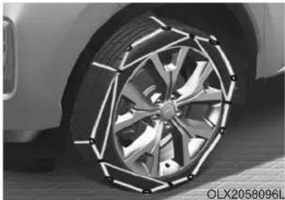
natural_image
Close-up of a car wheel rim with metallic and segmented design (no visible text or symbols)The mounting of some types of tire chains may cause damage to the tire. Therefore the use of snow tires is preferred over the use of tire chains.
If the road and weather conditions require the use of tire chains, be sure to use tire chains that have been properly selected for the size of tire on your HYUNDAI vehicle.
Be sure to follow the guidelines and installation instructions provided from the tire chain manufacturer.
Damage to your vehicle caused by improper tire chain use is not covered by your vehicle manufacturer's warranty.
When using tire chains, attach them to the drive wheels as follows.
2WD : Front wheels
AWD : Front wheels
Tire chains should be installed on the front wheels. This also applied an AWD vehicle.
WARNING
The use of tire chains may adversely affect vehicle handling:
- Drive less than 20 mph (30 km/h) or the chain manufacturer's recommended speed limit, whichever is lower.
- Drive carefully and avoid bumps, holes, sharp turns, and other road hazards, which may cause the vehicle to bounce.
- Avoid sharp turns or locked wheel braking.
i Information
• Install tire chains on both left and right front tires. It should be noted that installing tire chains on the tires will provide a greater driving force, but will not prevent side skids.
- Do not install studded tires without first checking local, state and municipal regulations for possible restrictions against their use.
Chain installation
When installing tire chains, follow the manufacturer's instructions and mount them as tightly possible. Drive slowly (less than 20 mph (30 km/h)) with chains installed. If you hear the chains contacting the body or chassis, stop and tighten them. If they still make contact, slow down until the noise stops. Remove the tire chains as soon as you begin driving on cleared roads.
When mounting snow chains, park the vehicle on level ground away from traffic. Turn on the vehicle Hazard Warning Flasher and place a triangular emergency warning device behind the vehicle (if available). Always place the vehicle in P (Park), apply the parking brake and turn off the engine before installing snow chains.
NOTICE
- When using tire chains:
- Wrong size chains or improperly installed chains can damage your vehicle's brake lines, suspension, body and wheels.
- Use SAE "S" class or wire chains.
- If you hear noise caused by chains contacting the body, retighten the chain to prevent contact with the vehicle body.
- To prevent body damage, retighten the chains after driving 0.3\~0.6 miles (0.5\~1.0 km).
- Do not use tire chains on vehicles equipped with aluminum wheels. If unavoidable, use a wire type chain.
- Use wire chains less than 0.59 inch (15 mm) wide to prevent damage to the chain's connection.
Winter Precautions
Use high quality ethylene glycol coolant
Your vehicle is delivered with high quality ethylene glycol coolant in the cooling system. It is the only type of coolant that should be used because it helps prevent corrosion in the cooling system, lubricates the water pump and prevents freezing. Be sure to replace or replenish your coolant in accordance with the maintenance schedule in chapter 7. Before winter, have your coolant tested to assure that its freezing point is sufficient for the temperatures anticipated during the winter.
Change to "winter weight" oil if necessary
In some climates it is recommended that a lower viscosity "winter weight" oil be used during cold weather. See chapter 8 for recommendations. If you aren't sure what weight oil you should use, consult an authorized HYUNDAI dealer.
Check battery and cables
Winter puts additional burdens on the battery system. Visually inspect the battery and cables as described in chapter 7. The level of charge in your battery can be checked by an authorized HYUNDAI dealer or a service station.
Check spark plugs and ignition system
Inspect your spark plugs as described in chapter 7 and replace them if necessary. Also check all ignition wiring and components to be sure they are not cracked, worn or damaged in any way.
Use approved window washer anti-freeze in system
To keep the water in the window washer system from freezing, add an approved window washer anti-freeze solution in accordance with instructions on the container. Window washer anti-freeze is available from an authorized HYUNDAI dealer and most auto parts outlets. Do not use engine coolant or other types of anti-freeze as these may damage the paint finish.
Do not let your parking brake freeze
Under some conditions your parking brake can freeze in the engaged position. This is most likely to happen when there is an accumulation of snow or ice around or near the rear brakes or if the brakes are wet. If there is a risk the parking brake may freeze, apply it only temporarily while you put the gear in P and block the rear wheels so the car cannot roll. Then release the parking brake.
Do not let ice and snow accumulate underneath
Under some conditions, snow and ice can build up under the fenders and interfere with the steering. When driving in severe winter conditions where this may happen, you should periodically check underneath the car to be sure the movement of the front wheels and the steering components is not obstructed.
Don't place foreign objects or materials in the engine compartment
Placement of foreign object or materials which prevent cooling of the engine, in the engine compartment, may cause a failure or combustion. The manufacturer is not responsible for the damage caused by such placement.
To keep locks from freezing
To keep the locks from freezing, squirt an approved de-icer fluid or glycerine into the key opening. If a lock is covered with ice, squirt it with an approved de-icing fluid to remove the ice. If the lock is frozen internally, you may be able to thaw it out by using a heated key. Handle the heated key with care to avoid injury.
TRAILER TOWING
If you are considering to tow with your vehicle, you should first check with your state's Department of Motor Vehicles to determine legal requirements. Since laws vary from state to state the requirements for towing trailers, vehicles, or other types of vehicles or apparatus may differ. Ask an authorized HYUNDAI dealer for further details before towing.
Remember that trailering is different than just driving your vehicle by itself. Trailering means changes in handling, durability, and fuel economy. Successful, safe trailering requires correct equipment, and it has to be used properly. Damage to your vehicle caused by improper trailer towing is not covered by your vehicle manufacturer's warranty.
This section contains many time-tested, important trailering tips and safety rules. Many of these are important for your safety and that of your passengers. Please read this section carefully before you pull a trailer.
WARNING
Take the following precautions:
- If you don't use the correct towing equipment, or if you drive improperly while towing, you can lose control of the vehicle when pulling a trailer. For example, if the trailer is too heavy, the braking performance may be reduced. You and your passengers could be seriously or fatally injured. Pull a trailer only if you have followed all the steps in this section.
- Before towing, make sure the total trailer weight, GCW (Gross Combination Weight), GVW (Gross Vehicle Weight), GAW (Gross Axle Weight) and trailer tongue load are all within the limits.
- When you tow a trailer, make sure to turn off the Idle Stop and Go system.
If you decide to pull a trailer
Here are some important points if you decide to pull a trailer:
- Consider using a sway control. You can ask a trailer hitch dealer about sway control.
- Do not do any towing with your vehicle during its first 1,200 miles (2,000 km) in order to allow the engine to properly break in. Failure to heed this caution may result in serious engine or transmission damage.
- When towing a trailer, be sure to consult an authorized HYUNDAI dealer for further information on additional requirements such as a towing kit, etc.
• Always drive your vehicle at a moderate speed (less than 60 mph (100 km/h)) or posted towing speed limit.
- On a long uphill grade, do not exceed 45 mph (70 km/h) or the posted towing speed limit, whichever is lower.
- Carefully observe the weight and load limits provided in the following pages.
Total trailer weight
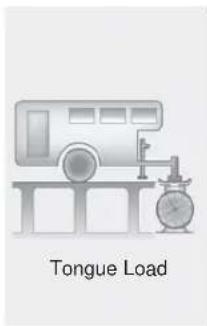
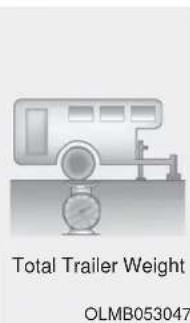
What is the maximum safe weight of a trailer? It should never weigh more than the maximum trailer weight with trailer brakes. But even that can be too heavy. It depends on how you plan to use your trailer. For example, speed, altitude, road grades, outside temperature and how often your vehicle is used to pull a trailer are all important. The ideal trailer weight can also depend on any special equipment that you have on your vehicle.
Tongue load
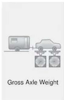
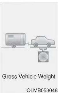
The tongue load is an important weight to measure because it affects the total Gross Vehicle Weight (GVW) of your vehicle. The trailer tongue should weigh a maximum of 10% of the total loaded trailer weight, within the limits of the maximum trailer tongue load permissible.
After you've loaded your trailer, weigh the trailer and then the tongue, separately, to see if the weights are proper. If they aren't, you may be able to correct them simply by moving some items around in the trailer.
WARNING
Take the following precautions:
- Never load a trailer with more weight in the rear than in the front. The front should be loaded with approximately 60% of the total trailer load; the rear should be loaded with approximately 40% of the total trailer load.
- Never exceed the maximum weight limits of the trailer or trailer towing equipment. Improper loading can result in damage to your vehicle and/or personal injury. Check weights and loading at a commercial scale or highway patrol office equipped with scales.
Reference weight and distance when towing a trailer
lbs (kg)
| Item 7 seater 8 seater | |||
| Maximum trailer weight | Without brake system | 1,653 (750) | 1,653 (750) |
| With brake system 5000 (2267) | 5000 (2267) | ||
| Maximum permissible static vertical load on the coupling device | 350 (159) | 350 (159) | |
Trailer towing equipment
Hitches
It's important to have the correct hitch equipment. Crosswinds, large trucks going by, and rough roads are a few reasons why you'll need the right hitch. Here are some rules to follow:
- The bumpers on your vehicle are not intended for hitches. Do not attach rental hitches or other bumper-type hitches to them. Use only a frame-mounted hitch that does not attach to the bumper.
- A HYUNDAI trailer hitch accessory is available at an authorized HYUNDAI dealer.
Safety chains
You should always attach chains between your vehicle and your trailer. Cross the safety chains under the tongue of the trailer so that the tongue will not drop to the road if it becomes separated from the hitch. Instructions about safety chains may be provided by the hitch manufacturer or trailer manufacturer. Follow the manufacturer's recommendation for attaching safety chains. Always leave just enough slack so you can turn with your trailer. And, never allow safety chains to drag on the ground.
Trailer brakes
If your trailer is equipped with a braking system, make sure it conforms to federal and/or local regulations and that it is properly installed and operating correctly.
If your trailer weighs more than the maximum trailer weight without trailer brakes loaded, then it needs its own brakes and they must be adequate. Be sure to read and follow the instructions for the trailer brakes so you'll be able to install, adjust and maintain them properly. Do not tap into your vehicle's brake system. Trailer brakes must be applied separately from your vehicle's brake system.
WARNING
Do not use a trailer with its own brakes unless you are absolutely certain that you have properly set up the brake system. Use an experienced, competent trailer shop for this work.
Driving with a trailer
Towing a trailer requires a certain amount of experience. Before setting out for the open road, you must get to know your trailer. Acquaint yourself with the feel of handling and braking with the added weight of the trailer. And always keep in mind that the vehicle you are driving is now longer and not nearly as responsive as your vehicle is by itself.
Before you start, check the trailer hitch and platform, safety chains, electrical connector(s), lights, tires and brakes.
During your trip, occasionally check to be sure that the load is secure, and that the lights and trailer brakes are still working.
Distance
Stay at least twice as far behind the vehicle ahead as you would when driving your vehicle without a trailer. This can help you avoid situations that require heavy braking and sudden turns.
Passing
You will need more passing distance up ahead when you're towing a trailer. And, because of the increased vehicle length, you'll need to go much farther beyond the passed vehicle before you can return to your lane.
Backing up
Hold the bottom of the steering wheel with one hand. Then, to move the trailer to the left, move your hand to the left. To move the trailer to the right, move your hand to the right. Always back up slowly and, if possible, have someone guide you.
Making turns
When you're turning with a trailer, make wider turns than normal. Do this so your trailer won't strike soft shoulders, curbs, road signs, trees, or other objects. Avoid jerky or sudden maneuvers. Signal well in advance.
Turn signals
When you tow a trailer, your vehicle has to have a different turn signal flasher and extra wiring. The green arrows on your instrument panel will flash whenever you signal a turn or lane change. Properly connected, the trailer lights will also flash to alert other drivers you're about to turn, change lanes, or stop.
When towing a trailer, the green arrows on your instrument panel will flash for turns even if the bulbs on the trailer are burned out. Thus, you may think drivers behind you are seeing your signals when, in fact, they are not. It's important to check periodically to be sure the trailer bulbs are still working. You must also check the lights every time you disconnect and then reconnect the wires.
WARNING
Do not connect a trailer lighting system directly to your vehicle's lighting system. Use an approved trailer wiring harness. Failure to do so could result in damage to the vehicle electrical system and/or personal injury. Consult an authorized HYUNDAI dealer for assistance.
Driving on hills
Reduce speed and shift to a lower gear before you start down a long or steep downgrade. If you don't shift down, you might have to use your brakes so much that they would get overheated and may not operate efficiently.
On a long uphill grade, shift down and reduce your speed to around 45 mph (70 km/h) to reduce the possibility of engine and transmission overheating.
If your trailer weighs more than the maximum trailer weight without trailer brakes, you should drive in D (Drive) when towing a trailer. Operating your vehicle in D (Drive) when towing a trailer will minimize heat build-up and extend the life of your transmission.
NOTICE
To prevent engine and/or transmission overheating:
- When towing a trailer on steep grades (in excess of 6%) pay close attention to the engine coolant temperature gauge to ensure the engine does not overheat. If the needle of the coolant temperature gauge moves towards "H" (HOT), pull over and stop as soon as it is safe to do so, and allow the engine to idle until it cools down. You may proceed once the engine has cooled sufficiently.
- When towing a trailer, your vehicle speed may be much slower than the general flow of traffic, especially when climbing an uphill grade. Use the right hand lane when towing a trailer on an uphill grade. Choose your vehicle speed according to the maximum posted speed limit for vehicles with trailers, the steepness of the grade, and your trailer weight.
Parking on hills
Generally, if you have a trailer attached to your vehicle, you should not park your vehicle on a hill.
However, if you ever have to park your trailer on a hill, here's how to do it:
- Pull the vehicle into the parking area.
Turn the steering wheel in the direction of the curb (right if headed down hill, left if headed up hill).
- Shift the vehicle to P (Park).
- Set the parking brake and shut off the vehicle.
-
Place wheel chocks under the trailer wheels on the down hill side of the wheels.
-
Start the vehicle, apply the brakes, shift to neutral, release the parking brake and slowly release the brakes until the trailer chocks absorb the load.
- Reapply the brakes and parking brakes.
- Move the shift lever to P (Park).
- Shut off the vehicle and release the vehicle brakes but leave the parking brake set.
WARNING
- Do not get out of the vehicle without the parking brake firmly set. If you have left the engine running, the vehicle can move suddenly. You and others could be seriously or fatally injured.
- Do not apply the accelerator pedal to hold the vehicle on an uphill.
Driving the vehicle after it has been parked on a hill
-
With the gear shift lever in P (Park), apply the brakes and hold the brake pedal down while performing the following:
-
Start your engine;
- Shift into gear; and
-
Release the parking brake.
-
Slowly remove your foot from the brake pedal.
- Drive slowly until the trailer is clear of the chocks.
- Stop and have someone pick up and store the chocks.
Maintenance when trailer towing
Your vehicle will need service more often when you regularly pull a trailer. Important items to pay particular attention to include engine oil, automatic transmission fluid, axle lubricant and cooling system fluid. Brake condition is another important item to frequently check. If you're trailing, it's a good idea to review these items before you start your trip. Don't forget to also maintain your trailer and hitch. Follow the maintenance schedule that accompanied your trailer and check it periodically. Preferably, inspect the vehicle and trailer at the start of each day's driving. Inspect the hitch mounting to make sure the hitch is properly secured to the vehicle. Inspect the trailer electrical wiring to make sure brake lights, turn signal lights, running lights, and hazard lights are working properly.
NOTICE
To prevent vehicle damage:
- Due to higher load during trailer usage, overheating might occur on hot days or during uphill driving. If the coolant gauge indicates over-heating, switch off the air conditioner and stop the vehicle in a safe area to cool down the engine.
- When towing check the automatic transmission fluid more frequently.
VEHICLE LOAD LIMIT
Two labels on your driver's door sill show how much weight your vehicle was designed to carry: the Tire and Loading Information Label and the Certification Label.
Before loading your vehicle, familiarize yourself with the following terms for determining your vehicle's weight ratings, from the vehicle's specifications and the Certification Label:
Base Curb Weight
This is the weight of the vehicle including a full tank of fuel and all standard equipment. It does not include passengers, cargo, or optional equipment.
Vehicle Curb Weight
This is the weight of your new vehicle when you picked it up from your dealer plus any aftermarket equipment.
Cargo Weight
This figure includes all weight added to the Base Curb Weight, including cargo and optional equipment.
GAW (Gross Axle Weight)
This is the total weight placed on each axle (front and rear) - including vehicle curb weight and all payload.
GAWR (Gross Axle Weight Rating)
This is the maximum allowable weight that can be carried by a single axle (front or rear). These numbers are shown on the Certification Label. The total load on each axle must never exceed its GAWR.
GVW (Gross Vehicle Weight)
This is the Base Curb Weight plus actual Cargo Weight plus passengers.
GVWR (Gross Vehicle Weight Rating)
This is the maximum allowable weight of the fully loaded vehicle (including all options, equipment, passengers and cargo). The GVWR is shown on the Certification Label located on the driver's door sill.
Tire Loading Information Label
■ Type A
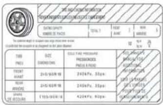
OLX2079056N
■ Type C
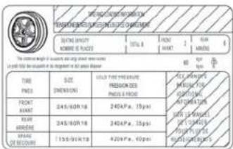
OLX2079058N
■ Type B
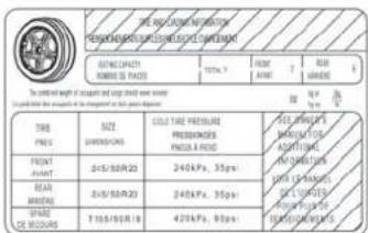
OLX2079057N
■ Type D
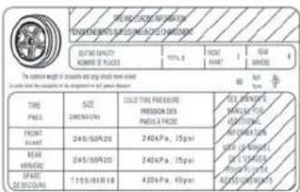
OLX2079059N
The label located on the driver's door sill gives the original tire size, cold tire pressures recommended for your vehicle, the number of people that can be in your vehicle and vehicle capacity weight.
Vehicle capacity weight
- 7 persons : 1173 lbs. (532 kg)
- 8 persons : 1323 lbs. (600 kg)
Vehicle capacity weight is the maximum combined weight of occupants and cargo. If your vehicle is equipped with a trailer, the combined weight includes the tongue load.
Seating capacity
- Total : 7 persons
(Front seat: 2 persons,
Rear seat:5 persons)
- Total : 8 persons
(Front seat : 2 persons,
Rear seat : 6 persons)
Seating capacity is the maximum number of occupants including a driver, your vehicle may carry. However, the seating capacity may be reduced based upon the weight of all of the occupants, and the weight of the cargo being carried or towed. Do not overload the vehicle as there is a limit to the total weight, or load limit including occupants and cargo, the vehicle can carry.
Cargo capacity
The cargo capacity of your vehicle will increase or decrease depending on the weight and the number of occupants and the tongue load, if your vehicle is equipped with a trailer.
Steps for determining correct load limit
- Locate the statement "The combined weight of occupants and cargo should never exceed XXX kg or XXX lbs." on your vehicle's placard.
- Determine the combined weight of the driver and passengers that will be riding in your vehicle.
- Subtract the combined weight of the driver and passengers from XXX kg or XXX lbs.
- The resulting figure equals the available amount of cargo and luggage load capacity. For example, if the "XXX" amount equals 1400 lbs. and there will be five 150 lb. passengers in your vehicle, the amount of available cargo and luggage load capacity is 650 lbs. (1400 - 750 (5 x 150) = 650 lbs.)
-
Determine the combined weight of luggage and cargo being loaded on the vehicle. That weight may not safely exceed the available cargo and luggage load capacity calculated in Step 4.
-
If your vehicle will be towing a trailer, load from your trailer will be transferred to your vehicle. Consult this manual to determine how this reduces the available cargo and luggage load capacity of your vehicle.
WARNING
Do not overload the vehicle as there is a limit to the total weight, or load limit, including occupants and cargo, the vehicle can carry. Overloading can shorten the life of the vehicle. If the GVWR or the GAWR is exceeded, parts on the vehicle can break, and it can change the handling of your vehicle. These could cause you to lose control and result in an accident.
| Example 1 | |||||
 | ≥slant |  | + |  | |
| Maximum Load(1400 lbs.)(635 kg) | Passenger Weight(150 lbs. × 2 = 300 lbs.)(68 kg × 2 = 136 kg) | Cargo Weight(1100 lbs.)(499 kg) | |||
| Example 2 | |||||
 | ≥slant |  | + |  | |
| Maximum Load(1400 lbs.)(635 kg) | Passenger Weight(150 lbs. × 5 = 750 lbs.)(68 kg × 5 = 340 kg) | Cargo Weight(650 lbs.)(295 kg) | |||
| Example 3 | |||||
 | ≥slant |  | + |  | |
| Maximum Load(1400 lbs.)(635 kg) | Passenger Weight(172 lbs. × 5 = 860 lbs.)(78 kg × 5 = 390 kg) | Cargo Weight(540 lbs.)(245 kg) | |||
Certification label
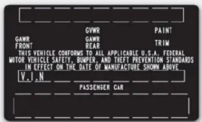
OBH059070
The certification label is located on the driver's door sill at the center pillar and shows the maximum allowable weight of the fully loaded vehicle. This is called the GVWR (Gross Vehicle Weight Rating). The GVWR includes the weight of the vehicle, all occupants, fuel and cargo.
This label also tells you the maximum weight that can be supported by the front and rear axles, called Gross Axle Weight Rating (GAWR).
The total weight of the vehicle, including all occupants, accessories, cargo, and trailer tongue load must not exceed the Gross Vehicle Weight Rating (GVWR) or the Gross Axle Weight Rating (GAWR). To find out the actual loads on your front and rear axles, you need to go to a weigh station and weigh your vehicle. Be sure to spread out your load equally on both sides of the centerline.

WARNING
Overloading
- Never exceed the GVWR for your vehicle, the GAWR for either the front or rear axle and vehicle capacity weight. Exceeding these ratings can affect your vehicle's handling and braking ability, and cause an accident.
- Do not overload your vehicle. Overloading your vehicle can cause heat buildup in your vehicle's tires and possible tire failure, increased stopping distances and poor vehicle handling-all of which may result in a crash.
NOTICE
Overloading your vehicle may cause damage. Repairs would not be covered by your warranty. Do not overload your vehicle.
WARNING
If you carry items inside your vehicle (e.g., suitcases, tools, packages, or anything else), they are moving as fast as the vehicle. If you have to stop or turn quickly, or if there is a crash, the items will keep going and can cause an injury if they strike the driver or a passenger.
- Put items in the cargo area of your vehicle. Try to spread the weight evenly.
- Do not stack items, like suit-cases, inside the vehicle above the tops of the seats.
- Do not leave an unsecured child restraint in your vehicle.
- When you carry something inside the vehicle, secure it.
What to do in an emergency
Hazard Warning Flasher 6-2
In Case of an Emergency While Driving......6-2
If the Engine Stalls While Driving 6-2
If the Engine Stalls at a Crossroad or Crossing......6-2
If you Have a Flat Tire While Driving 6-3
If the Engine Will Not Start....6-3
If the Engine Doesn't Turn Over or
Turns Over Slowly 6-3
If the Engine Turns Over Normally but
Doesn't Start 6-3
Jump Starting....6-4
If the Engine Overheats....6-6
Tire Pressure Monitoring System (TPMS)......6-8
Check Tire Pressure 6-8
Tire Pressure Monitoring System....6-9
Low Tire Pressure Telltale 6-10
Low Tire Pressure LCD Display with
Position Indicator 6-10
TPMS Malfunction Indicator 6-11
Changing a Tire with TPMS....6-12
If You Have a Flat Tire....6-14
Jack and Tools 6-14
Removing and Storing the Spare Tire 6-15
Changing Tires....6-16
Towing 6-22
Towing Service....6-22
Removable Towing Hook 6-23
Emergency Towing....6-24
HAZARD WARNING FLASHER

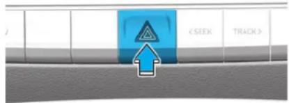
OLX2068001
The hazard warning flasher serves as a warning to other drivers to exercise extreme caution when approaching, overtaking, or passing your vehicle.
It should be used whenever emergency repairs are being made or when the vehicle is stopped near the edge of a roadway.
To turn the hazard warning flasher on or off, press the hazard warning flasher button. The button is located in the center fascia panel. Both the left and right turn signal lights will flash simultaneously.
- The hazard warning flasher operates whether your vehicle is running or not.
- The turn signals do not work when the hazard flasher is on.
IN CASE OF AN EMERGENCY WHILE DRIVING
If the Engine Stalls While Driving
- Reduce your speed gradually, keeping a straight line. Move cautiously off the road to a safe place.
- Turn on your hazard warning flash-er.
- Try to start the engine again. If your vehicle will not start, contact an authorized HYUNDAI dealer or seek other qualified assistance.
If the Engine Stalls at a Crossroad or Crossing
If the engine stalls at a crossroads or crossing, if safe to do so, move the shift button to the N (Neutral) position and then push the vehicle to a safe location.
If you Have a Flat Tire While Driving
If a tire goes flat while you are driving:
• Take your foot off the accelerator pedal and let the vehicle slow down while driving straight ahead. Do not apply the brakes immediately or attempt to pull off the road as this may cause loss of vehicle control resulting in an accident. When the vehicle has slowed to such a speed that it is safe to do so, brake carefully and pull off the road. Drive off the road as far as possible and park on firm, level ground. If you are on a divided highway, do not park in the median area between the two traffic lanes.
- When the vehicle is stopped, press the hazard warning flasher button, move the shift button into P (Park), and apply the parking brake, and place the ignition switch in the OFF position.
- Have all passengers get out of the vehicle. Be sure they all get out on the side of the vehicle that is away from traffic.
- When changing a flat tire, follow the instructions provided later in this chapter.
IF THE ENGINE WILL NOT START
If the Engine Doesn't Turn Over or Turns Over Slowly
- Be sure the shift button is in N (Neutral) or P (Park). The engine starts only when the shift button is in N (Neutral) or P (Park).
- Check the battery connections to be sure they are clean and tight.
- Turn on the interior light. If the light dims or goes out when you operate the starter, the battery is drained.
Do not push or pull the vehicle to start it. This could cause damage to your vehicle. See instructions for "Jump Starting" provided in this chapter.

CAUTION
Push or pull starting the vehicle may cause the catalytic converter to overload which can lead to damage to the emission control system.
If the Engine Turns Over Normally but Doesn't Start
Check the fuel level and add fuel if necessary.
If the engine still does not start, have your vehicle checked by an authorized HYUNDAI dealer.
JUMP STARTING
Jump starting can be dangerous if done incorrectly. Follow the jump starting procedure in this section to avoid serious injury or damage to your vehicle. If in doubt about how to properly jump start your vehicle, we strongly recommend that you have a service technician or towing service do it for you.
WARNING
To prevent SERIOUS INJURY or DEATH to you or bystanders, always follow these precautions when working near or handling the battery:

Always read and follow instructions carefully when handling a battery.

Wear eye protection designed to protect the eyes from acid splashes.

Keep all flames, sparks, or smoking materials away from the battery.

Hydrogen is always present in battery cells, is highly combustible, and may explode if ignited.

Keep batteries out of reach of children.

Batteries contain sulfuric acid which is highly corrosive. Do not allow acid to contact your eyes, skin or clothing.
If acid gets into your eyes, flush your eyes with clean water for at least 15 minutes and get immediate medical attention. If acid gets on your skin, thoroughly wash the area. If you feel pain or a burning sensation, get medical attention immediately.
- When lifting a plastic-cased battery, excessive pressure on the case may cause battery acid to leak. Lift with a battery carrier or with your hands on opposite corners.
- Do not attempt to jump start your vehicle if your battery is frozen.
- NEVER attempt to recharge the battery when the vehicle's battery cables are connected to the battery.
- The electrical ignition system works with high voltage. NEVER touch these components with the engine running or when the ignition switch is in the ON position.

Information

An inappropriately disposed battery can be harmful to the environment and human health. Dispose of the battery according to your local law(s) or regulations.
NOTICE
To prevent damage to your vehicle:
- Only use a 12-volt power supply (battery or jumper system) to jump start your vehicle.
- Do not attempt to jump start your vehicle by push-starting.
Jump starting procedure
-
Position the vehicles close enough that the jumper cables will reach, but do not allow the vehicles to touch.
-
Avoid fans or any moving parts in the engine compartment at all times, even when the vehicles are turned off.
-
Turn off all electrical devices such as radios, lights, air conditioning, etc. Put the vehicles in P (Park) and set the parking brakes. Turn both vehicles OFF.
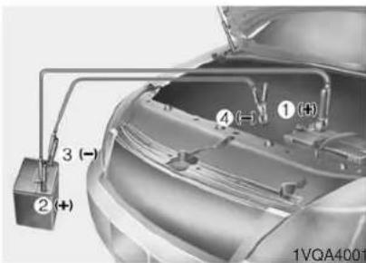
-
Connect the jumper cables in the exact sequence shown in the illustration. First connect one jumper cable to the red, positive (+) jumper terminal of your vehicle (1).
-
Connect the other end of the jumper cable to the red, positive (+) battery/jumper terminal of the assisting vehicle (2).
-
Connect the second jumper cable to the black, negative (-) battery/chassis ground of the assisting vehicle (3).
-
Connect the other end of the second jumper cable to the black, negative (-) chassis ground of your vehicle (4).
Do not allow the jumper cables to contact anything except the correct battery or jumper terminals or the correct ground. Do not lean over the battery when making connections.
-
Start the engine of the assisting vehicle and let it run at approximately 2,000 rpm for a few minutes. Then start your vehicle.
-
Operate your vehicle for at least 30 minutes of driving or at least 60 minutes of engine running at idle before shutting off the engine. Without sufficient time to charge the battery, another no-start will occur. You can also visit your nearest dealer to request the battery be charged and tested.
If your vehicle will not start after a few attempts, it probably requires servicing. In this event please seek qualified assistance. If the cause of your battery discharging is not apparent, have your vehicle checked by an authorized HYUNDAI dealer.
Disconnect the jumper cables in the exact reverse order you connected them:
-
Disconnect the jumper cable from the black, negative (-) chassis ground of your vehicle (4).
-
Disconnect the other end of the jumper cable from the black, negative (-) battery/chassis ground of the assisting vehicle (3).
-
Disconnect the second jumper cable from the red, positive (+) battery/jumper terminal of the assisting vehicle (2).
-
Disconnect the other end of the jumper cable from the red, positive (+) jumper terminal of your vehicle (1).
IF THE ENGINE OVERHEATS
If your temperature gage indicates overheating, you experience a loss of power, or hear loud pinging or knocking, the engine may be overheating. If this happens, you should:
-
Pull off the road and stop as soon as it is safe to do so.
-
Put the vehicle in P (Park) and set the parking brake. If the air conditioning is ON, turn it OFF.
-
If engine coolant is running out under the vehicle or steam is coming out from the hood, stop the engine. Do not open the hood until the coolant has stopped running or the steaming has stopped. If there is no visible loss of engine coolant and no steam, leave the engine running and check to be sure the engine cooling fan is operating. If the fan is not running, turn the engine off.
WARNING
While the engine is running, keep hands, clothing and tools away from the moving parts such as the cooling fan and drive belt to prevent serious injury.
- Check for coolant leaking from the radiator, hoses or under the vehicle. (If the air conditioning had been in use, it is normal for cold water to be draining from it when you stop.)
- If engine coolant is leaking out, stop the engine immediately and call the nearest authorized HYUNDAI dealer for assistance.
WARNING
Your vehicle is equipped with a pressurized coolant reserve tank. NEVER remove the radiator
cap or the drain plug while the engine and radiator are HOT. Hot coolant and steam may blow out under pressure, causing serious injury.
Turn the engine off and wait until the engine cools down. Use extreme care when removing the radiator cap. Wrap a towel or thick rag around it, and turn it counterclockwise slowly to release some of the pressure from the system. Step back while the pressure is released.
When you are sure all the pressure has been released, continue turning the cap counterclockwise to remove it.
- If you cannot find the cause of the overheating, wait until the engine temperature has returned to normal. Then, if coolant has been lost, carefully add coolant to the reservoir to bring the fluid level in the reservoir up to the halfway mark.
- Proceed with caution, keeping alert for further signs of overheating. If overheating happens again, call an authorized HYUNDAI dealer for assistance.
CAUTION
Serious loss of coolant indicates a leak in the cooling system and should be checked as soon as possible by an authorized HYUNDAI dealer.
TIRE PRESSURE MONITORING SYSTEM (TPMS)
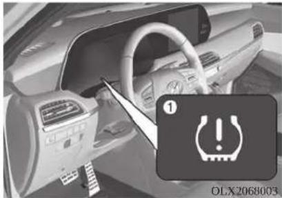
natural_image
Interior view of a car dashboard with steering wheel and dashboard, showing a warning icon (no readable text or symbols)
OLX2068004L
(1) Low Tire Pressure / TPMS Malfunction Indicator Lamp
(2) Low Tire Pressure / Tire Pressure Monitor / TPMS Malfunction Display (shown on the cluster LCD display)
Check Tire Pressure
OLX2048120L
- You can check the tire pressure in the Assist mode on the cluster. Refer to the "LCD Display Mode" section in chapter 3.
- A "Drive to display" message will appear for the first few minutes of driving after initial engine start up. If the tire pressure is not displayed after a few minutes of driving, check the tire pressures.
• The displayed tire pressure values may differ from those measured with a tire pressure gage.
- You can change the tire pressure unit in the User Settings mode on the cluster.
- psi, kpa, bar (Refer to the "User Settings Mode" section in chapter 3).
Tire Pressure Monitoring System
WARNING
Over-inflation or under-inflation can reduce tire life, adversely affect vehicle handling, and lead to sudden tire failure that may cause loss of vehicle control resulting in an accident.
Each tire, including the spare (if provided), should be checked monthly when cold and inflated to the inflation pressure recommended by the vehicle manufacturer on the vehicle placard or tire inflation pressure label. (If your vehicle has tires of a different size than the size indicated on the vehicle placard or tire inflation pressure label, you should determine the proper tire inflation pressure for those tires.)
As an added safety feature, your vehicle has been equipped with a tire pressure monitoring system (TPMS) that illuminates a low tire pressure telltale when one or more of your tires is significantly under-inflated. Accordingly, when the low tire pressure telltale illuminates, you should stop and check your tires as soon as possible, and inflate them to the proper pressure. Driving on a significantly under-inflated tire causes the tire to overheat and can lead to tire failure.
Under-inflation also reduces fuel efficiency and tire tread life, and may affect the vehicle's handling and stopping ability.
Please note that the TPMS is not a substitute for proper tire maintenance, and it is the driver's responsibility to maintain correct tire pressure, even if under-inflation has not reached the level to trigger illumination of the TPMS low tire pressure telltale.
Your vehicle has also been equipped with a TPMS malfunction indicator to indicate when the system is not operating properly. The TPMS malfunction indicator is combined with the low tire pressure telltale. When the system detects a malfunction, the telltale will flash for approximately one minute and then remain continuously illuminated. This sequence will continue upon subsequent vehicle start-ups as long as the malfunction exists.
When the malfunction indicator is illuminated, the system may not be able to detect or signal low tire pressure as intended. TPMS malfunctions may occur for a variety of reasons, including the installation of replacement or alternate tires or wheels on the vehicle that prevent the TPMS from functioning properly.
Always check the TPMS malfunction telltale after replacing one or more tires or wheels on your vehicle to ensure that the replacement or alternate tires and wheels allow the TPMS to continue to function properly.
NOTICE
If any of the below happens, have the system checked by an authorized HYUNDAI dealer.
- The Low Tire Pressure TPMS Malfunction Indicator does not illuminate for 3 seconds when the ignition switch is placed to the ON position or engine is running.
- The TPMS Malfunction Indicator remains illuminated after blinking for approximately 1 minute.
- The Low Tire Pressure LCD display remains illuminated
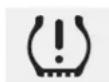
Low Tire Pressure Telltale
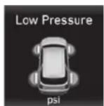
Low Tire Pressure LCD Display with Position Indicator
OLX2068004L
When the tire pressure monitoring system warning indicators are illuminated and the warning message is displayed on the cluster LCD display, one or more of your tires is significantly under-inflated. The LCD position indicator will indicate which tire is significantly under-inflated by illuminating the corresponding position light.
If any of your tire pressures are indicated as being low, immediately reduce your speed, avoid hard cornering, and anticipate increased stopping distances. You should stop and check your tires as soon as possible. Inflate the tires to the proper pressure as indicated on the vehicle's placard or tire inflation pressure label located on the driver's side center pillar outer panel.
If you cannot reach a service station or if the tire cannot hold the newly added air, replace the low pressure tire with the spare tire.
The Low Tire Pressure LCD position indicator will remain on and the TPMS Malfunction Indicator may blink for one minute and then remain illuminated until you have the low pressure tire repaired and replaced on the vehicle.
NOTICE
The spare tire is not equipped with a tire pressure sensor.
CAUTION
In winter or cold weather, the Low Tire Pressure Telltale may be illuminated if the tire pressure was adjusted to the recommended tire inflation pressure in warm weather. It does not mean your TPMS is malfunctioning because the decreased temperature leads to a proportional lowering of tire pressure. When you drive your vehicle from a warm area to a cold area or from a cold area to a warm area, or the outside temperature is greatly higher or lower, you should check the tire inflation pressure and adjust the tires to the recommended tire inflation pressure.
WARNING
Low pressure damage
Significantly low tire pressure makes the vehicle unstable and can contribute to loss of vehicle control and increased braking distances.
Continued driving on low pressure tires can cause the tires to overheat and fail.

TPMS Malfunction Indicator
The TPMS Malfunction Indicator will illuminate after it blinks for approximately one minute when there is a problem with the Tire Pressure Monitoring System.
Have the system checked by an authorized HYUNDAI dealer as soon as possible.
NOTICE
If there is a malfunction with the TPMS, the individual tire pressures in the cluster LCD display will not be available. Have the system checked by an authorized HYUNDAI dealer as soon as possible.
NOTICE
The TPMS Malfunction Indicator may illuminate after blinking for one minute if the vehicle is near electric power supply cables or radio transmitters such as police stations, government and public offices, broadcasting stations, military installations, airports, transmitting towers, etc.
Additionally, the TPMS Malfunction Indicator may illuminate if snow chains are used or electronic devices such as computers, chargers, remote starters, navigation, etc. This may interfere with normal operation of the TPMS.
Changing a Tire with TPMS
If you have a flat tire, the Low Tire Pressure and LCD position indicator will come on. Have the flat tire repaired by an authorized HYUNDAI dealer as soon as possible or replace the flat tire with the spare tire.
CAUTION
Never use a puncture-repairing agent not approved by HYUNDAI dealer to repair and/or inflate a low pressure tire. Tire sealant not approved by HYUNDAI dealer may damage the tire pressure sensor.
The spare tire does not come with a tire pressure monitoring sensor. When the low pressure tire or the flat tire is replaced with the spare tire, the Low Tire Pressure LCD position indicator will remain on. Also, the TPMS Malfunction Indicator will illuminate after blinking for one minute if the vehicle is driven at speed above 15.5 mph (25 km/h) for approximately 20 minutes.
Once the original tire equipped with a tire pressure monitoring sensor is reinflated to the recommended pressure and reinstalled on the vehicle, the Low Tire Pressure LCD position indicator and TPMS Malfunction Indicator will go off within a few minutes of driving.
If the indicators do not disappear after a few minutes, please visit an authorized HYUNDAI dealer.
Each wheel is equipped with a tire pressure sensor mounted inside the tire behind the valve stem (except for the spare tire). You must use TPMS specific wheels. It is recommended that you always have your tires serviced by an authorized HYUNDAI dealer.
You may not be able to identify a tire with low pressure by simply looking at it. Always use a good quality tire pressure gauge to measure the tire's inflation pressure. Please note that a tire that is hot (from being driven) will have a higher pressure measurement than a tire that is cold.
A cold tire means the vehicle has been sitting for 3 hours and driven for less than 1 mile (1.6 km) in that 3 hour period.
Allow the tire to cool before measuring the inflation pressure. Always be sure the tire is cold before inflating to the recommended pressure.
WARNING
- The TPMS cannot alert you to severe and sudden tire damage caused by external factors such as nails or road debris.
- If you feel any vehicle instability, immediately take your foot off the accelerator, apply the brakes gradually with light force, and slowly move to a safe position off the road.
WARNING
Tampering with, modifying, or disabling the Tire Pressure Monitoring System (TPMS) components may interfere with the system's ability to warn the driver of low tire pressure conditions and/or TPMS malfunctions. Tampering with, modifying, or disabling the Tire Pressure Monitoring System (TPMS) components may void the warranty for that portion of the vehicle.
i Information
This device complies with Part 15 of the FCC rules.
Operation is subject to the following three conditions:
- This device may not cause harmful interference.
- This device must accept any interference received, including interference that may cause undesired operation.
- Changes or modifications not expressly approved by the party responsible for compliance could void the user's authority to operate the equipment.
IF YOU HAVE A FLAT TIRE
WARNING
Changing a tire can be dangerous. Follow the instructions in this section when changing a tire to reduce the risk of serious injury or death.
CAUTION
Be careful as you use the jack handle to stay clear of the flat end. The flat end has sharp edges that could cause cuts.
Jack and Tools
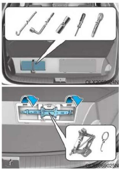
⑥ Screwdriver
⑦ Towing hook
The jack, jack handle, wheel lug nut wrench and socket are stored in the luggage compartment under the luggage box cover.
The jack is provided for emergency tire changing only.
① Jack handle
② Jack
⑤ Wheel cap removing tool
Removing and Storing the Spare Tire

natural_image
Close-up of a car air vent with two circular buttons and a central dial, showing no text or symbols.Your spare tire is stored underneath your vehicle, directly below the cargo area.
To remove the spare tire:
-
Open the liftgate.
-
Find the plastic hex bolt cover and remove the cover with a coin or flat-blade screwdriver.
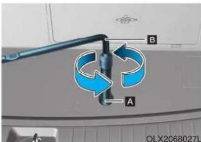
-
Connect the socket (A) and wheel lug nut wrench (B).
-
Loosen the bolt enough to lower the spare tire.
Turn the wrench counterclockwise until the spare tire reaches the ground.
- After the spare tire reaches the ground, continue to turn the wrench counterclockwise, and draw the spare tire outside. Never rotate the wrench excessively, otherwise the spare tire carrier may be damaged.
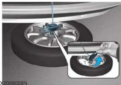
natural_image
Mechanical diagram showing a car tire being inserted into a component, with a magnified inset highlighting the tool (no text or symbols present)- Draw out the retainer guide (1) through the center hole of the spare tire.
To store the spare tire:
- Lay the tire on the ground with the valve stem facing up.
- Place the wheel under the vehicle and install the retainer guide and chain through the wheel center.
- Turn the wrench clockwise until it clicks.

CAUTION
Ensure the spare tire retainer guide is properly aligned with the center of the spare tire to prevent the spare tire from "rattling".
Otherwise, it may cause the spare tire to fall off the carrier and lead to an accident.
Changing Tires
WARNING
A vehicle can slip or roll off of a jack causing serious injury or death to you or those nearby. Take the following safety precautions:
- Never place any portion of your body under a vehicle that is supported by a jack.
- NEVER attempt to change a tire in the lane of traffic. ALWAYS move the vehicle completely off the road on level, firm ground away from traffic before trying to change a tire. If you cannot find a level, firm place off the road, call a towing service for assistance.
- Be sure to use the jack provided with the vehicle.
-
ALWAYS place the jack on the designated jacking positions on the vehicle and NEVER on the bumpers or any other part of the vehicle for jacking support.
-
Do not start or run the engine while the vehicle is on the jack.
- Do not allow anyone to remain in the vehicle while it is on the jack.
- Keep children away from the road and the vehicle.
Follow these steps to change your vehicle's tire:
- Park on a level, firm surface.
- Move the shift button into P (Park), apply the parking brake, and place the ignition switch in the OFF position.
- Press the hazard warning flasher button.
- Remove the wheel lug nut wrench, jack, jack handle, wheel cap remover (big cap only) and spare tire from the vehicle.
- Block both the front and rear of the tire diagonally opposite of the tire you are changing.
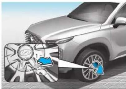
natural_image
Illustration of a car front view with a magnified inset showing a steering wheel and steering wheel (no text or symbols)- Insert the tool (1, if equipped) into the hole and pull out the wheel cover.
NOTICE
When removing the wheel cover, if you use any other tool except the tool (1) provided, the wheel cover may be damaged.
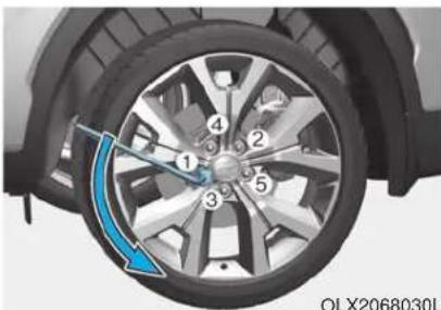
natural_image
Close-up of a car wheel with numbered components and a blue curved arrow indicating rotation (no text or symbols)- Loosen the wheel lug nuts counterclockwise one turn each in the order shown above, but do not remove any lug nuts until the tire has been raised off of the ground.
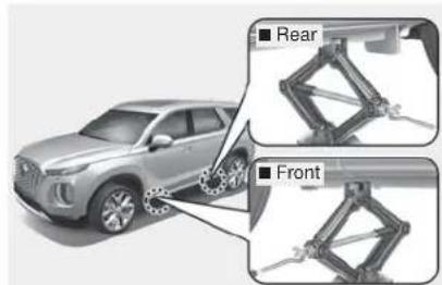
OLX2068030LOLX2069034N OIX2068031L
8. Place the jack at the designated jacking position under the frame closest to the tire you are changing. The jacking positions are plates welded to the frame with two notches. Never jack at any other position or part of the vehicle. Doing so may damage the side seal molding or other parts of the vehicle.
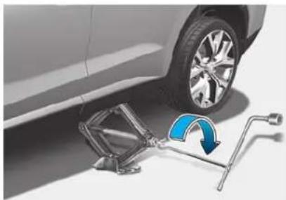
natural_image
Diagram showing a car tire mounted on a lift next to a blue curved arrow indicating rotation (no text or symbols present)-
Insert the jack handle into the jack and turn it clockwise, raising the vehicle until the tire clears the ground. Make sure the vehicle is stable on the jack.
-
Loosen the lug nuts with the wheel lug nut wrench and remove them with your fingers. Remove the wheel from the studs and lay it flat on the ground out of the way. Remove any dirt or debris from the studs, mounting surfaces, and wheel.
- Install the spare tire onto the studs of the hub.
- Tighten the lug nuts with your fingers onto the studs with the smaller end of the lug nuts closest to the wheel.
- Lower the vehicle to the ground by turning the jack handle counterclockwise.
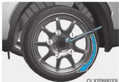
natural_image
Close-up of a car wheel with numbered segments and a blue arrow indicating clockwise motion (no text or symbols)OLX2068033LOLX2068032L
14. Use the wheel lug nut wrench to tighten the lug nuts in the order shown. Double-check each lug nut until they are tight. After changing tires, have an authorized HYUNDAI dealer tighten the lug nuts to their proper torque as soon as possible. The wheel lug nut should be tightened to 79\~94 lbf·ft (11\~13 kgf·m).
If you have a tire gauge, check the tire pressure (see "Tires and Wheels" in chapter 8 for tire pressure instructions.). If the pressure is lower or higher than recommended, drive slowly to the nearest service station and adjust it to the recommended pressure. Always reinstall the valve cap after checking or adjusting tire pressure. If the cap is not replaced, air may leak from the tire. If you lose a valve cap, buy another and install it as soon as possible. After changing tires, secure the flat tire and return the jack and tools to their proper storage locations. If it is hard to secure the flat tire, put the flat tire in the luggage compartment.
NOTICE
- Check the tire pressure as soon as possible after installing a spare tire. Adjust it to the recommended pressure.
- Check and tighten the wheel lug nuts after driving over 30 mile (50 km) if tires are replaced. Recheck the tire wheel lug nuts after driving over 600 mile (1,000 km).
CAUTION
Your vehicle has metric threads on the studs and lug nuts. Make certain during tire changing that the same nuts that were removed are reinstalled. If you have to replace your lug nuts make sure they have metric threads to avoid damaging the studs and ensure the wheel is properly secured to the hub. Consult an authorized HYUNDAI dealer for assistance.
If any of the equipment such as the jack, lug nuts, studs, or other equipment is damaged or in poor condition, do not attempt to change the tire and call for assistance.
Use of compact spare tires
Compact spare tires are designed for emergency use only. Drive carefully on the compact spare tire and always follow the safety precautions.
WARNING
To prevent compact spare tire failure and loss of control possibly resulting in an accident:
- Use the compact spare tire only in an emergency.
- NEVER operate your vehicle over 50 mph (80 km/h).
- Do not exceed the vehicle's maximum load rating or the load carrying capacity shown on the sidewall of the compact spare tire.
- Do not use the compact spare tire continuously. Repair or replace the original tire as soon as possible to avoid failure of the compact spare tire.
When driving with the compact spare tire mounted to your vehicle:
- Check the tire pressure after installing the compact spare tire. The compact spare tire should be inflated to 60 psi (420 kPa).
- Do not take this vehicle through an automatic car wash while the compact spare tire is installed.
- Do not use the compact spare tire on any other vehicle because this tire has been designed especially for your vehicle.
- The compact spare tire's tread life is shorter than a regular tire. Inspect your compact spare tire regularly and replace worn compact spare tires with the same size and design, mounted on the same wheel.
- Do not use more than one compact spare tire at a time.
- Do not tow a trailer while the compact spare tire is installed.
NOTICE
When the original tire and wheel are repaired and reinstalled on the vehicle, the lug nut torque must be set correctly. The correct lug nut tightening torque is 79\~94 lbf·ft (11\~13 kgf·m).
CAUTION
To prevent damaging the compact spare tire and your vehicle:
- Drive slowly enough for the road conditions to avoid all hazards, such as a potholes or debris.
- Avoid driving over obstacles. The compact spare tire diameter is smaller than the diameter of a conventional tire and reduces the ground clearance approximately 1 inch (25 mm).
- Do not use tire chains on the compact spare tire. Because of the smaller size, a tire chain will not fit properly.
- Do not use the compact spare tire on any other wheels, nor should standard tires, snow tires, wheel covers or trim rings be used with the compact spare wheel.
Jack label
Example
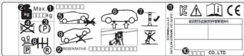
OOS067043
The actual Jack label in the vehicle may differ from the illustration.
For more detailed specifications, refer to the label attached to the jack.
- Model Name
2.Maximum allowable load - When using the jack, set your parking brake.
- When using the jack, stop the engine.
5.Do not get under a vehicle that is supported by a jack. - The designated locations under the frame
-
When supporting the vehicle, the base plate of jack must be vertical under the lifting point.
-
Shift into Reverse gear on vehicles with manual transmission or move the shift button to the P (Park) position on vehicles with automatic transmission.
- The jack should be used on firm level ground.
- Jack manufacture
- Production date
- Representative company and address
TOWING
Towing Service
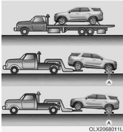
natural_image
Three illustrations of a pickup truck on a flatbed trailer, showing different scenarios of loading or repair (no text or symbols present)If emergency towing is necessary, we recommend having it done by an authorized HYUNDAI dealer or a commercial tow-truck service. Proper lifting and towing procedures are necessary to prevent damage to the vehicle. The use of wheel dollies or flatbed is recommended.
On 2WD vehicles, it is acceptable to tow the vehicle with the rear wheels on the ground (without dollies) and the front wheels off the ground. If any of the loaded wheels or suspension components are damaged or the vehicle is being towed with the front wheels on the ground, use a towing dolly under the front wheels.
When being towed by a commercial tow truck and wheel dollies are not used, the front of the vehicle should always be lifted, not the rear.
If your vehicle is an AWD vehicle, it must be towed with a wheel lift and dollies or flatbed equipment with all the wheels off the ground.
NOTICE
An AWD vehicle should never be towed with the wheels on the ground. This can cause serious damage to the transaxle or the AWD system.
NOTICE
- Do not tow the vehicle with the front wheels on the ground as this may cause damage to the vehicle.
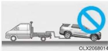
natural_image
Illustration of a truck and a car with a blue prohibition symbol (no text or labels)- Do not tow with sling-type equipment. Use a wheel lift or flatbed equipment.
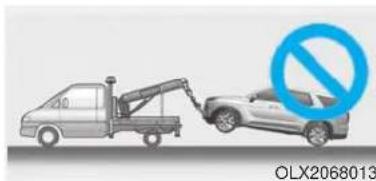
natural_image
Illustration of a tow truck and car with a blue prohibition symbol (no text or labels on the diagram itself)WARNING
If your vehicle is equipped with a rollover sensor, place the ignition switch in the OFF or ACC position when the vehicle is being towed. The side impact and curtain air bag may deploy if the sensor detects the situation as a rollover.
When towing your vehicle in an emergency without wheel dollies:
- Place the ignition switch in the ACC position.
- Place the shift button in N (Neutral).
- Release the parking brake.
CAUTION
Failure to place the shift button in N (Neutral) when being towed with the front wheels on the ground can cause internal damage to the transmission.
Removable Towing Hook
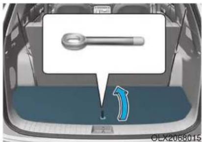
- Open the liftgate, and remove the towing hook from the tool case.
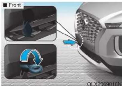
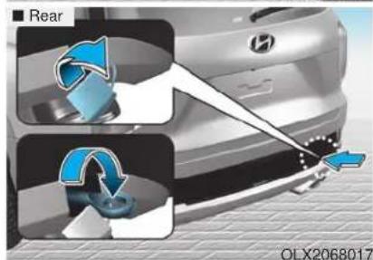
- Remove the hole cover by pressing the lower part of the cover on the front or rear bumper.
- Install the towing hook by turning it clockwise into the hole until it is fully secured.
- Remove the towing hook and install the cover after use.
Emergency Towing
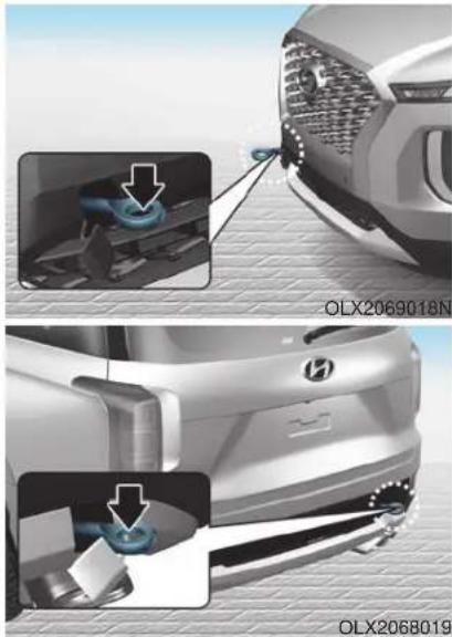
natural_image
Two-step car door repair procedure showing blue-hand valve installation and mounting details (no text or symbols)If towing is necessary, we recommend you have it done by an authorized HYUNDAI dealer or a commercial tow truck service.
If towing service is not available in an emergency, your vehicle may be temporarily towed using a cable or chain secured to the emergency towing hook at the front (or rear) of the vehicle.
Use extreme caution when towing the vehicle with a cable or chain. A driver must be in the vehicle to steer it and operate the brakes.
Towing in this manner may be done only on hard-surfaced roads for a short distance and at low speeds. Also, the wheels, axles, power train, steering and brakes must all be in good condition.
CAUTION
The driver must be in the vehicle for steering and braking operations when the vehicle is being towed. Passengers other than the driver must not be in the vehicle.
Always follow these emergency towing precautions:
- While depressing the brake pedal shift to the N (Neutral) position and turn the vehicle off. The POWER button will be in the ACC position.
- Release the parking brake.
- Depress the brake pedal with more force than normal since you will have reduced braking performance.
- More steering effort will be required because the power steering system will be disabled.
- Use a vehicle heavier than your own to tow your vehicle.
- The drivers of both vehicles should communicate with each other frequently.
- Before emergency towing, check that the hook is not broken or damaged.
- Fasten the towing cable or chain securely to the hook.
- Do not jerk the hook. Apply steady and even force.
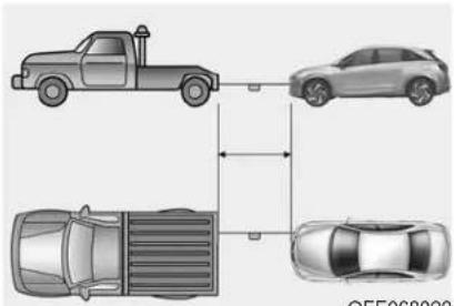
- Use a towing cable or chain less than 16 feet (5 m) long. Attach a white or red cloth (about 12 inch (30 cm) wide) in the middle of the cable or chain for easy visibility.
- Drive carefully so the towing cable or chain remains tight during towing.
- Before towing, check the reduction gear for fluid leaks under your vehicle. If the reduction gear is leaking, flatbed equipment or a towing dolly must be used.
NOTICE
Accelerate or decelerate the vehicle in a slow and gradual manner while maintaining tension on the tow rope or chain to start or drive the vehicle, otherwise tow hooks and the vehicle may be damaged.
NOTICE
To avoid damage to your vehicle and vehicle components when towing:
• Always pull straight ahead when using the towing hooks. Do not pull from the side or at a vertical angle.
- Do not use the towing hooks to pull a vehicle out of mud, sand or other conditions from which the vehicle cannot be driven out under its own power.
- Limit the vehicle speed to 10 mph (15 km/h) and drive less than 1 mile (1.5 km) when towing to avoid serious damage to the reduction gear.
Maintenance
Engine compartment 7-3
Maintenance services ....7-4 Owner's Responsibility....7-4 Owner Maintenance Precautions....7-4
Owner maintenance....7-5 Owner Maintenance Schedule....7-6
Scheduled maintenance services....7-7 Normal Maintenance Schedule (3.8 GDI)....7-8 Maintenance Under Severe Usage Conditions (3.8 GDI)....7-11
Explanation of scheduled maintenance items.7-13
Engine oil ....7-16 Checking the Engine Oil Level ....7-16 Checking the Engine Oil and Filter ....7-17
Engine coolant....7-18 Checking the Engine Coolant Level....7-18 Changing Engine Coolant....7-20
Brake fluid ....7-21 Checking the Brake Fluid Level....7-21
Washer fluid ....7-22 Checking the Washer Fluid Level....7-22
Air cleaner ....7-22 Filter Replacement....7-22
Climate control air filter ....7-24 Filter Inspection....7-24
Wiper blades....7-26 Blade Inspection....7-26 Blade Replacement....7-26
Battery....7-29 For Best Battery Service ....7-30 Battery Recharging ....7-31 Reset Features....7-32
Tires and wheels....7-33 Tire Care....7-33 Recommended Cold Tire Inflation Pressures....7-34 Check Tire Inflation Pressure....7-35 Tire Rotation....7-35
Wheel Alignment and Tire Balance ....7-36 Tire Replacement ....7-37 Wheel Replacement ....7-38
Tire Traction....7-38 Tire Maintenance....7-39 Tire Sidewall Labeling....7-39
Tire Terminology and Definitions....7-43 All Season Tires....7-46 Snow Tires....7-46 Radial-Ply Tires....7-46
Fuses....7-48
Instrument Panel Fuse Replacement....7-49
Engine Compartment Panel Fuse Replacement.....7-50
Fuse/Relay Panel Description....7-51
Light bulbs....7-61
Headlamp, Parking lamp, Daytime Running Light,
Turn signal lamp and Side marker....7-61
Side Repeater Lamp Replacement....7-64
Rear combination lamp light replacement .....7-64
High Mounted Stop Lamp Bulb Replacement .....7-66
License Plate Light Bulb Replacement .....7-66
Interior Light Bulb Replacement 7-67
Appearance care....7-69
Exterior Care....7-69
Interior Care 7-74
Emission control system 7-77
Crankcase Emission Control System 7-77
Evaporative Emission Control System Including
Onboard Refueling Vapor Recovery (ORVR)....7-77
Exhaust Emission Control System 7-78
California perchlorate notice 7-81
ENGINE COMPARTMENT
■ 3.8 GDI
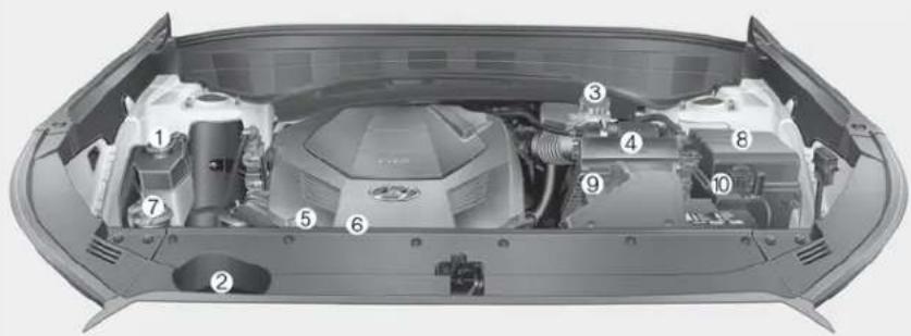
- Engine coolant reservoir
- Radiator cap
- Brake fluid reservoir
- Air cleaner
- Engine oil dipstick
- Engine oil filler cap
- Windshield washer fluid reservoir
- Fuse box
- Battery terminal [+]
- Battery terminal [-]
The actual engine compartment in the vehicle may differ from the illustration.
The actual engine compartment in the vehicle may differ from the illustration.
OLX2078002L
MAINTENANCE SERVICES
You should exercise the utmost care to prevent damage to your vehicle and injury to yourself whenever performing any maintenance or inspection procedures.
We recommend you have your vehicle maintained and repaired by an authorized HYUNDAI dealer. An authorized HYUNDAI dealer meets HYUNDAI's high service quality standards and receives technical support from HYUNDAI in order to provide you with a high level of service satisfaction.
Owner's Responsibility
Maintenance service and record retention are the owner's responsibility.
You should retain documents that show proper maintenance has been performed on your vehicle in accordance with the scheduled maintenance service charts shown on the following pages. You need this information to establish your compliance with the servicing and maintenance requirements of your vehicle warranties.
Detailed warranty information is provided in your Owner's Handbook & Warranty Information booklet.
Repairs and adjustments required as a result of improper maintenance or a lack of required maintenance are not covered.
Owner Maintenance Precautions
Inadequate, incomplete or insufficient servicing may result in operational problems with your vehicle that could lead to vehicle damage, an accident, or personal injury. This chapter provides instructions only for the maintenance items that are easy to perform. Several procedures can be done only by an authorized HYUNDAI dealer with special tools.
Your vehicle should not be modified in any way. Such modifications may adversely affect the performance, safety or durability of your vehicle and may, in addition, violate conditions of the limited warranties covering the vehicle.
Certain modifications may also be in violation of regulations established by the U.S. Department of Transportation and other federal or state agencies.
NOTICE
Improper owner maintenance during the warranty period may affect warranty coverage. For details, read the separate Owner's Handbook & Warranty Information booklet provided with the vehicle. If you're unsure about any service or maintenance procedure, have it done by an authorized HYUNDAI dealer.
OWNER MAINTENANCE
WARNING
Performing maintenance work on a vehicle can be dangerous. If you lack sufficient knowledge and experience or the proper tools and equipment to do the work, have it done by an authorized HYUNDAI dealer.
ALWAYS follow these precautions for performing maintenance work:
- Park your vehicle on level ground, move the shift button into the P (Park) position, place the ignition switch in the OFF position.
- Block the tires (front and back) to prevent the vehicle from moving.
Remove loose clothing or jewelry that can become entangled in moving parts. - If you must run the engine during maintenance, do so out doors or in an area with plenty of ventilation.
- Keep flames, sparks, or smoking materials away from the battery and fuel-related parts.
The following lists are vehicle checks and inspections that should be performed by the owner or an authorized HYUNDAI dealer at the frequencies indicated to help ensure safe, dependable operation of your vehicle.
Any adverse conditions should be brought to the attention of your dealer as soon as possible.
These Owner Maintenance vehicle checks are generally not covered by warranties and you may be charged for labor, parts and lubricants used.
Owner Maintenance Schedule
When you stop for fuel:
- Check the engine oil level.
- Check the coolant level in the engine coolant reservoir.
- Check the windshield washer fluid level.
- Check the tire for low or under-inflated tires.
WARNING
Be careful when checking your engine coolant level when the engine is hot. This may result in coolant being blown out of the opening and cause serious burns and other injuries.
While operating your vehicle:
- Note any changes in the sound of the exhaust or any smell of exhaust fumes in the vehicle.
- Check for vibrations in the steering wheel. Notice if there is any increased steering effort or looseness in the steering wheel, or change in its straight-ahead position.
- Notice if your vehicle constantly turns slightly or "pulls" to one side when traveling on smooth, level road.
- When stopping, listen and check for unusual sounds, pulling to one side, increased brake pedal travel or "hard-to-push" brake pedal.
- If any slipping or changes in the operation of your transmission occurs, check the transmission fluid level.
-
Check the automatic transmission P (Park) function.
-
Check the parking brake.
- Check for fluid leaks under your vehicle (water dripping from the air conditioning system during or after use is normal).
At least monthly:
- Check coolant level in the engine coolant reservoir.
- Check the operation of all exterior lights, including the brake lights, turn signals and hazard warning flashers.
- Check the inflation pressures of all tires including the spare for tires that are worn, show uneven wear, or are damaged.
- Check for loose wheel lug nuts.
At least twice a year:
(i.e., every Spring and Autumn)
- Check radiator, heater and air conditioning hoses for leaks or damage.
-
Check windshield washer spray and wiper operation. Clean wiper blades with a clean cloth dampened with washer a fluid.
-
Check headlamp alignment.
- Check muffler, exhaust pipes, shields and clamps.
- Check seat belts for wear and function.
At least once a year:
- Clean body and door drain holes.
- Lubricate door hinges and hood hinges.
- Lubricate door and hood locks and latches.
- Lubricate door rubber weather strips.
- Lubricate door checker.
- Check the air conditioning system.
- Inspect and lubricate automatic transmission linkage and controls.
- Clean the battery and terminals.
- Check the brake fluid level.
SCHEDULED MAINTENANCE SERVICES
Follow Normal Maintenance Schedule if the vehicle is usually operated where none of the following conditions apply. If any of the following conditions apply, you must follow the Maintenance Under Severe Usage Conditions.
• Repeatedly driving short distances of less than 5 miles (8 km) in normal temperature or less than 10 miles (16 km) in freezing temperature
- Extensive engine idling or low speed driving for long distances
- Driving on rough, dusty, muddy, unpaved, graveled or salt- spread roads
- Driving in areas using salt or other corrosive materials or in very cold weather
- Driving in heavy dust conditions
- Driving in heavy traffic area
- Driving on uphill, downhill, or mountain road
- Towing a trailer, or using a camper, or roof rack
- Driving as a patrol car, taxi, other commercial use or vehicle towing
- Driving over 106 mph (170 km/h)
- Frequently driving in stop-and-go conditions
For additional information or assistance see your authorized HYUNDAI dealer.
Normal Maintenance Schedule (3.8 GDI)
| MAINTENANCEINTERVALS | Number of months or driving distance, whichever comes first | ||||||||||||||||
| Months 12 24 | 36 | 48 | 60 | 72 | 84 | 96 | 108 | 120 | 132 | 144 | 156 | 168 | 180 | ||||
| Miles×1,000 | 7.5 | 15 | 22.5 | 30 | 37.5 | 45 | 52.5 | 60 | 67.5 | 75 | 82.5 | 90 | 97.5 | 105 | 112.5 | ||
| Km×1,000 | 12 | 24 | 36 | 48 | 60 | 72 | 84 | 96 | 108 | 120 | 132 | 144 | 156 | 168 | 180 | ||
| Drive belts *1 | At first, inspect at 60,000 miles (96,000 km) or 72 months,after that, inspect every 15,000 miles (24,000 km) or 24 months | ||||||||||||||||
| Engine oil and engine oil filter | R | R | R | R | R | R | R | R | R | R | R | R | R | R | R | R | |
| Fuel additives *2 | Add every 7,500 miles (12,000 km) or 12 months | ||||||||||||||||
| Air cleaner filter | I | I | R | I | I | R | I | I | R | I | I | R | I | I | I | R | |
| Spark plugs | Replace every 97,500 miles (156,000 km) | ||||||||||||||||
| Valve clearance *3 | Inspect every 60,000 miles (96,000 km) or 72 months | ||||||||||||||||
| Rotate tires | Rotate every 7,500 miles (12,000 km) | ||||||||||||||||
1: Inspect and if necessary, adjust, correct, clean or replace.
R : Replace or change.
* : The drive belt should be replaced when cracks occur or tension is reduced.
* : If TOP TIER Detergent Gasoline is not available, one bottle of additive is recommended. Additives are available from your authorized HYUNDAI dealer along with information on how to use them. Do not mix other additives.
* : Inspect for excessive valve noise and/or engine vibration and adjust if necessary. Have an authorized authorized HYUNDAI dealer perform the operation.
Normal Maintenance Schedule (3.8 GDI) (CONT.)
| MAINTENANCEINTERVALSMAINTENANCEITEM | Number of months or driving distance, whichever comes first | |||||||||||||||
| Months 12 | 24 | 36 | 48 | 60 | 72 | 84 | 96 | 108 | 120 | 132 | 144 | 156 | 168 | 180 | ||
| Miles×1,000 | 7.5 | 15 | 22.5 | 30 | 37.5 | 45 | 52.5 | 60 | 67.5 | 75 | 82.5 | 90 | 97.5 | 105 | 112.5 | |
| Km×1,000 | 12 | 24 | 36 | 48 | 60 | 72 | 84 | 96 | 108 | 120 | 132 | 144 | 156 | 168 | 180 | |
| Climate control air filter (if equipped) | R | R | R | R | R | R | R | R | R | R | R | R | R | R | R | |
| Vacuum hose | I | I | I | I | I | I | I | I | I | I | I | I | I | I | I | |
| Engine coolant | At first, replace at 120,000 miles (192,000 km) or 10 years :after that, replace every 30,000 miles (48,000 km) or 24 months | |||||||||||||||
| Battery condition | I | I | I | I | I | I | I | I | I | I | I | I | I | I | I | |
| Brake lines, hoses and connections | I | I | I | I | I | I | I | I | I | I | I | I | I | I | I | |
| Disc brakes and pads | I | I | I | I | I | I | I | I | I | I | I | I | I | I | I | |
| Steering gear rack, linkage and boots | I | I | I | I | I | I | I | I | I | I | I | I | I | I | I | |
| Driveshaft and boots | I | I | I | I | I | I | I | |||||||||
| Suspension mounting bolts | I | I | I | I | I | I | I | I | I | I | I | I | I | I | I | |
| Air conditioner refrigerant | I | I | I | I | I | I | I | I | I | I | I | I | I | I | I | |
| Air conditioner compressor | I | I | I | I | I | I | I | I | I | I | I | I | I | I | I | |
| Propeller shaft (AWD) | I | I | I | I | I | I | I | |||||||||
| Exhaust pipe and muffler | I | I | I | I | I | I | I | I | I | I | I | I | I | I | I | |
1: Inspect and if necessary, adjust, correct, clean or replace.
R : Replace or change.
Normal Maintenance Schedule (3.8 GDI) (CONT.)
| MAINTENANCEINTERVALS | Number of months or driving distance, whichever comes first | |||||||||||||||
| Months 12 | 24 | 36 | 48 | 60 | 72 | 84 | 96 | 108 | 120 | 132 | 144 | 156 | 168 | 180 | ||
| MAINTENANCEITEM | Miles×1,000 | 7.5 | 15 | 22.5 | 30 | 37.5 | 45 | 52.5 | 60 | 67.5 | 75 | 82.5 | 90 | 97.5 | 105 | 112.5 |
| Km×1,000 | 12 | 24 | 36 | 48 | 60 | 72 | 84 | 96 | 108 | 120 | 132 | 144 | 156 | 168 | 180 | |
| Automatic transmission fluid | No check, No service required | |||||||||||||||
| Rear differential oil (AWD) *1 | I | I | ||||||||||||||
| Transfer case oil (AWD) *1 | I | I | ||||||||||||||
| Vapor hose, fuel filler cap and fuel tank | I | I | I | I | I | I | ||||||||||
| Fuel tank air filter *5 | I | I | I | I | I | I | ||||||||||
| Fuel filter *5 | I | I | I | I | I | I | ||||||||||
| Fuel lines, hoses and connections | I | I | I | |||||||||||||
| Parking brake | I | I | I | I | I | I | ||||||||||
| Brake fluid | I | I | I | I | I | I | ||||||||||
1: Inspect and if necessary, adjust, correct, clean or replace.
R : Replace or change.
* : Rear differential oil and transfer case oil should be changed anytime they have been submerged in water.
* : Fuel filter & Fuel tank air filter are considered to be maintenance free but periodic inspection is recommended for this maintenance schedule depends on fuel quality. If there are some important safety matters like fuel flow restriction, surging, loss of power, hard starting problem, etc. replace the fuel filter immediately regardless of maintenance schedule and consult an authorized HYUNDAI dealer for details.
Maintenance Under Severe Usage Conditions (3.8 GDI)
The following items must be serviced more frequently on cars normally used under severe driving conditions. Refer to the chart below for the appropriate maintenance intervals.
R: Replace or change.
I: Inspect and if necessary, adjust, correct, clean or replace.
| MAINTENANCE ITEM | MAINTENANCE OPERATION | MAINTENANCE INTERVALS | DRIVING CONDITION |
| Engine oil and filter | R | Every 3,750 miles (6,000 km) or 6 months | A, B, C, D, E, F, G, H, I, J, K |
| Air cleaner filter R More frequently C, E | |||
| Spark plugs | R | More frequently A, B, H, I, K | |
| Automatic transaxle fluid | R | Every 60,000 miles (96,000 km) A, C, D, E, F, G, H, I | |
| Front brake disc/pads, calipers I More frequently C, D, G, H | |||
| Rear brake disc/pads I More frequently C, D, G, H | |||
| Parking brake | I | More frequently | C, D, G, H |
| Steering gear box, linkage & boots/Lower arm ball joint, upper arm ball joint | I More frequently C, D, E, F, G, H, I | ||
| Drive shafts and boots I | Every 3,750 miles (6,000 km) or 6 months | C, D, E, F, G, H, I, J | |
| Rear differential oil | R | Every 75,000 miles (120,000 km) C, G, H, I, J | |
| Transfer case oil (AWD) | R | Every 75,000 miles (120,000 km) C, G, H, I, J | |
| Climate control air filter(for evaporator and blower unit) | R | More frequently C, E | |
| Propeller shaft I | Every 7,500 miles (12,000 km) or 6 months | C, E |
Severe driving conditions
A-Repeatedly driving short distance of less than 5 miles (8 km) in normal temperature or less than 10 miles (16 km) in freezing temperature
B-Extensive engine idling or low speed driving for long distances
C-Driving on rough, dusty, muddy, unpaved, graveled or salt-spread roads
D-Driving in areas using salt or other corrosive materials or in very cold weather
E-Driving in heavy dust condition
F -Driving in heavy traffic area
G-Driving on uphill, downhill, or mountain road repeatedly
H-Towing a Trailer, or using a camper, or roof rack
I -Driving as a patrol car, taxi, other commercial use or vehicle towing
J -Driving over 106 mph (170 km/h)
K-Frequently driving in stop-and-go conditions
EXPLANATION OF SCHEDULED MAINTENANCE ITEMS
Engine Oil and Filter
The engine oil and filter should be changed at the intervals specified in the maintenance schedule. If the vehicle is being driven in severe conditions, more frequent oil and filter changes are required.
Drive Belts
Inspect all drive belts for evidence of cuts, cracks, excessive wear or oil saturation and replace if necessary. Drive belts should be checked periodically for proper tension and adjusted as necessary.
Fuel Filter
A clogged-up fuel filter may limit the vehicle driving speed, damage the emission system, and cause the hard starting. When a considerable amount of foreign substances are accumulated in the fuel tank, the fuel filter should be replaced.
Upon installing a new fuel filter, operate the engine for several minutes, and check the connections for any leakages. Fuel filters should be installed by an authorized HYUNDAI dealer.
Fuel Lines, Fuel Hoses and Connections
Check the fuel lines, fuel hoses and connections for leakage and damage. Have an authorized HYUNDAI dealer replace any damaged or leaking parts immediately.
Vapor Hose and Fuel Filler Cap
The vapor hose and fuel filler cap should be inspected at those intervals specified in the maintenance schedule. Make sure a new vapor hose or fuel filler cap is correctly replaced.
Vacuum Crankcase Ventilation Hoses
Inspect the surface of hoses for evidence of heat and/or mechanical damage. Hard and brittle rubber, cracking, tears, cuts, abrasions, and excessive swelling indicate deterioration. Particular attention should be paid to examine those hose surfaces nearest to high heat sources, such as the exhaust manifold.
Inspect the hose routing to ensure that the hoses do not come in contact with any heat source, sharp edges or moving component which might cause heat damage or mechanical wear. Inspect all hose connections, such as clamps and couplings, to make sure they are secure, and that no leaks are present. Hoses should be replaced immediately if there is any evidence of deterioration or damage.
Air Cleaner Filter
A genuine HYUNDAI air cleaner filter is recommended when the filter is replaced.
Spark Plugs
Make sure to install new spark plugs of the correct heat range.
Cooling System
Check cooling system components, such as radiator, coolant reservoir, hoses and connections for leakage and damage. Replace any damaged parts.
Engine Coolant
The coolant should be changed at the intervals specified in the maintenance schedule.
Automatic Transmission Fluid
Automatic transmission fluid should not be checked under normal usage conditions. But in severe conditions, the fluid should be changed at an authorized HYUNDAI dealer in accordance to the scheduled maintenance at the beginning of this chapter.
i Information
Automatic transmission fluid color is red when new.
As the vehicle is driven, the automatic transmission fluid will begin to look darker. This is a normal condition and you should not judge the need to replace the fluid based upon the changed color.
NOTICE
The use of a non-specified fluid could result in transmission malfunction and failure. Use only the specified automatic transmission fluid (refer to "Recommended Lubricants and Capacities" in chapter 8).
Brake Hoses and Lines
Visually check for proper installation, chafing, cracks, deterioration and any leakage. Replace any deteriorated or damaged parts immediately.
Brake Fluid
Check the brake fluid level in the brake fluid reservoir. The level should be between the MIN and the MAX marks on the side of the reservoir. Use only hydraulic brake fluid conforming to DOT 3 or DOT 4 specification.
Parking Brake
Inspect the parking brake system.
Brake Discs, Pads, Calipers and Rotors
Check the pads for excessive wear, discs for run out and wear, and calipers for fluid leakage.
Exhaust Pipe and Muffler
Visually inspect the exhaust pipes, muffler and hangers for cracks, deterioration, or damage. Start the engine and listen carefully for any exhaust gas leakage. Tighten connections or replace parts as necessary.
Suspension Mounting Bolts
Check the suspension connections for looseness or damage. Retighten to the specified torque.
Steering Gear Box, Linkage & Boots/Lower Arm Ball Joint
With the vehicle stopped and the engine off, check for excessive free-play in the steering wheel. Check the linkage for bends or damage. Check the dust boots and ball joints for deterioration, cracks, or damage.
Replace any damaged parts.
Drive Shafts and Boots
Check the drive shafts, boots and clamps for cracks, deterioration, or damage. Replace any damaged parts and, if necessary, repack the grease.
Air Conditioning Refrigerant
Check the air conditioning lines and connections for leakage and damage.
ENGINE OIL
Checking the Engine Oil Level
- Follow all of the oil manufacturer's precautions.
- Be sure the vehicle is on the level ground in P (Park) with the parking brake set. If possible, block the wheels.
- Turn the engine on and allow the engine to reach normal operating temperature.
- Turn the engine off and wait about five minutes for the oil to return to the oil pan.
- Pull the dipstick out, wipe it clean, and re-insert it fully.
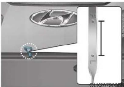
natural_image
Close-up of a car engine component with a highlighted tool and dimension line (no readable text or symbols)- Pull the dipstick out again and check the level. The level should be between F and L.
OLX2078006
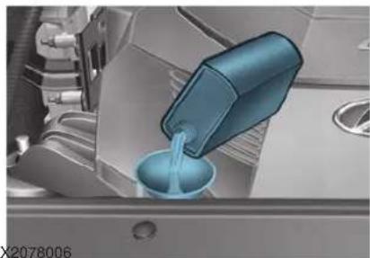
natural_image
Close-up of a blue mechanical component pouring liquid into a container (no visible text or symbols)- If it is near or at L, add enough oil to bring the level to F.
Use only the specified engine oil. (refer to "Recommended Lubricants and Capacities" in chapter 8).
NOTICE
To prevent damage to your engine:
- Do not overfill with engine oil. Add oil in small quantities and recheck level to ensure engine is not overfilled.
- Do not spill engine oil when adding or changing engine oil. Use a funnel to help prevent oil from being spilled on engine components. Wipe off spilled oil immediately.
Checking the Engine Oil and Filter
Have engine oil and filter changed by an authorized HYUNDAI dealer according to the Maintenance Schedule at the beginning of this chapter.

WARNING
CALIFORNIA PROPOSITION 65 WARNING
Engine oil contains chemicals known to the State of California to cause cancer, birth defects and reproductive harm. Used engine oil may cause irritation or cancer of the skin if left in contact with the skin for prolonged periods of time. Always protect your skin by washing your hands thoroughly with soap and warm water as soon as possible after handling used oil.
For more information go to https://www.p65warnings.ca.gov/passenger-vehicle
ENGINE COOLANT
The high-pressure cooling system has a reservoir filled with year-round antifreeze coolant. The reservoir is filled at the factory.
Check the antifreeze protection and coolant level at least once a year, at the beginning of the winter season and before traveling to a colder climate.
Checking the Engine Coolant Level
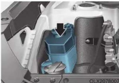
natural_image
Interior view of a mechanical assembly showing internal components (no visible text or symbols)Check the condition and connections of all cooling system hoses and heater hoses. Replace any swollen or deteriorated hoses.
The coolant level should be filled between the F and the L marks on the side of the coolant reservoir when the engine is cool.
If the coolant level is low, add enough distilled (deionized) water to bring the level to the F mark, but do not overfill. If frequent additions are required, see an authorized HYUNDAI dealer for a cooling system inspection.
Recommended engine coolant
- When adding coolant, use only distilled (deionized) water for your vehicle and never mix hard water in the coolant filled at the factory.
- An improper coolant mixture can result in severe malfunction or engine damage.
• The engine in your vehicle has aluminum engine parts and must be protected by an ethylene-glycol with phosphate based coolant to prevent corrosion and freezing. - Do not use alcohol or methanol coolant or mix them with the specified coolant.
- Do not use a solution that contains more than 60% antifreeze or less than 35% antifreeze, which would reduce the effectiveness of the solution.
For mixing percentage, refer to the following table:
| Ambient Temperature | Mixture Percentage (volume) | |
| Antifreeze Water | ||
| 5°F (-15°C) | 35 65 | |
| -13°F (-25°C) | 40 60 | |
| -31°F (-35°C) | 50 50 | |
| -49°F (-45°C) | 60 40 | |
i Information
If in doubt about the mix ratio, a 50% water and 50% antifreeze mix is the easiest to mix together as it will be the same quantity of each. It is suitable to use for most temperature ranges of -31°F and higher.
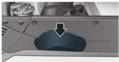
natural_image
Close-up of a mechanical component with a highlighted blue area and arrow indicating a specific section (no text or symbols visible)OLX2078008
WARNING
Never remove the radiator cap or the drain plug while the engine and radiator are hot. Hot coolant and steam may blow out under pressure, causing serious injury.
Turn the engine off and wait until the engine cools down. Use extreme care when removing the radiator cap. Wrap a thick towel around it, and turn it counterclockwise slowly to the first stop.
Step back while the pressure is released from the cooling system. When you are sure all the pressure has been released, press down on the cap, using a thick towel, and continue turning counterclockwise to remove it.
WARNING
The electric motor for the cooling fan may continue to operate or start up when the engine is not running and can cause serious injury. Keep hands, clothing and tools away from the rotating fan blades of the cooling fan.
Always turn off the engine unless the vehicle has to be inspected with the engine on. Be cautious as the cooling fan may operate if the negative (-) battery terminal is not disconnected.
Changing Engine Coolant
Have coolant changed by an authorized HYUNDAI dealer according to the Maintenance Schedule at the beginning of this chapter.
WARNING
Do not use engine coolant or antifreeze in the washer fluid reservoir.
Engine coolant can severely obscure visibility when sprayed on the windshield and may cause loss of vehicle control resulting in an accident.
Engine coolant may also cause damage to paint and body trim.
NOTICE
To prevent damage to engine parts, put a thick towel around the radiator cap before refilling the coolant to prevent the coolant from overflowing into engine parts, such as the alternator.
BRAKE FLUID
Checking the Brake Fluid Level
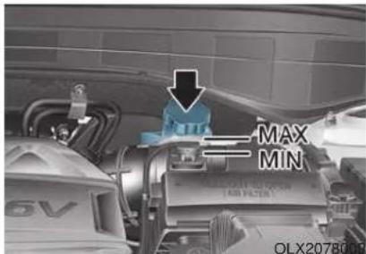
Check the fluid level in the reservoir periodically. The fluid level should be between MAX and MIN marks on the side of the reservoir.
Before removing the reservoir cap and adding brake fluid, clean the area around the reservoir cap thoroughly to prevent brake fluid contamination.
If the level is low, add the specified brake fluid to the MAX level. The level will fall with accumulated mileage. This is a normal condition associated with the wear of the brake linings. If the fluid level is excessively low, have the brake system checked by an authorized HYUNDAI dealer.
WARNING
If the brake system requires frequent additions of fluid this could indicate a leak in the brake system. Have the vehicle inspected by an authorized HYUNDAI dealer.
WARNING
Do not allow brake fluid to come in contact with your eyes. If brake fluid comes in contact with your eyes, flush your eyes with clean water for at least 15 minutes and get immediate medical attention.
NOTICE
- Do not allow brake fluid to contact the vehicle's body paint, as paint damage will result.
- Brake fluid, which has been exposed to open air for an extended time should NEVER be used as its quality cannot be guaranteed. It should be disposed of properly.
- Do not use the incorrect brake fluid. A few drops of mineral based oil, such as engine oil, in your brake system can damage brake system parts.
i Information
Use only the specified brake fluid (refer to "Recommended Lubricants and Capacities" in chapter 8).
WASHER FLUID
Checking the Washer Fluid Level
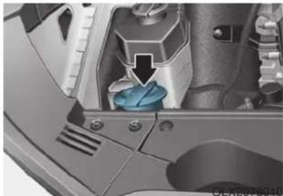
natural_image
Close-up of a mechanical component with a blue plastic component inserted, showing internal parts and a black arrow pointing to a feature (no text or symbols visible)Check the fluid level in the washer fluid reservoir and add fluid if necessary. Plain water may be used if washer fluid is not available. However, use washer solvent with antifreeze characteristics in cold climates to prevent freezing.
WARNING
To prevent serious injury or death, take the following safety precautions when using washer fluid:
- Do not use engine coolant or antifreeze in the washer fluid reservoir.
Engine coolant can severely obscure visibility when sprayed on the windshield and may cause loss of vehicle control resulting in an accident or damage to paint and body trim.
- Do not allow sparks or flames to contact the washer fluid or the washer fluid reservoir. Washer fluid may contain alcohol and can be flammable.
- Do not drink washer fluid and avoid contact with skin. Washer fluid is harmful to humans and animals.
- Keep washer fluid away from children and animals.
AIR CLEANER
Filter Replacement
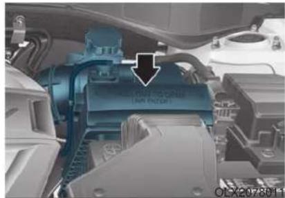
natural_image
Close-up of a car engine bay with a blue internal component and an arrow pointing to it, no visible text or symbols.The air cleaner filter can be cleaned for inspection using compressed air. Do not attempt to wash or to rinse it, as water will damage the filter.
If soiled, the air cleaner filter must be replaced.
Replace the filter according to the Maintenance Schedule.
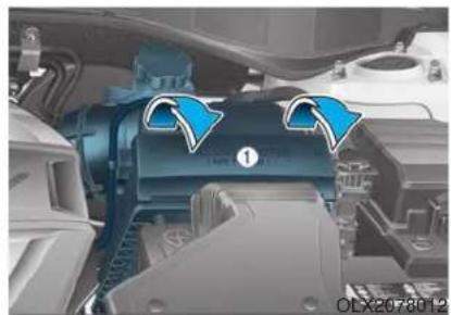
natural_image
Close-up of a car engine compartment with blue arrows indicating airflow or flow direction (no text or symbols)- Pull down the air cleaner filter cover (1).
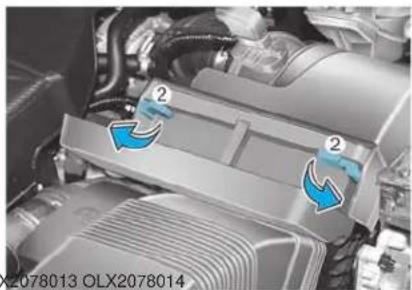
natural_image
Close-up of a car engine bay with blue arrows indicating flow or movement, no visible text or symbols- Pull down the lever (2) to the UNLOCK position.
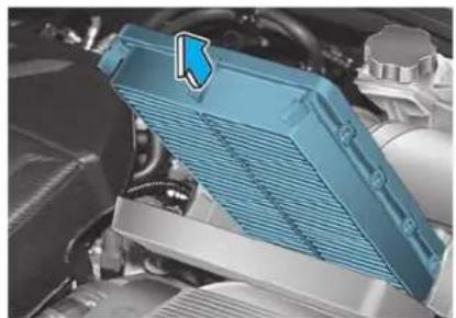
natural_image
Close-up of a car engine bay with blue filter cover and mechanical components (no visible text or symbols)- Replace the air cleaner filter.
- Reassemble the air cleaner cover in the reverse order.
- Check that the cover is firmly installed.
i Information
If the vehicle is operated in extremely dusty or sandy areas, replace the air cleaner filter more often than the usual recommended intervals (refer to "Maintenance Under Severe Usage Conditions" in this chapter).
NOTICE
- Do not drive with the air cleaner filter removed. This will result in excessive engine wear.
- When removing the air cleaner filter, be careful that dust or dirt does not enter the air intake, or damage may result.
- Use HYUNDAI genuine parts. Use of non-genuine parts could damage the air flow sensor.
CLIMATE CONTROL AIR FILTER
Filter Inspection
The climate control air filter should be replaced according to the Maintenance Schedule. If the vehicle is operated in severely air-polluted cities or on dusty rough roads for a long period and/or if transporting pets or occupants smoke inside the vehicle, then it should be inspected more frequently and replaced sooner. Replace the climate control air filter by following the procedure below and be careful to avoid damaging other components.
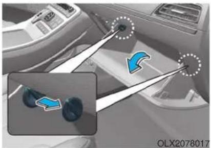
natural_image
Interior view of a car showing steering wheel and gear shift icons (no text or symbols)- With the glove box open, remove the stoppers on both sides to allow the glove box to hang freely on the hinges.
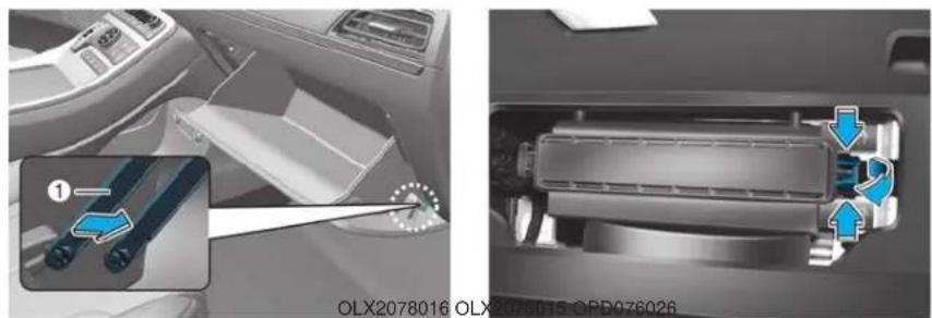
natural_image
Interior view of a car showing the dashboard and air vent system with blue arrows indicating flow direction (no text or symbols)- Remove the support rod (1). 3. Remove the climate control air filter case while pressing the lock on right side of the cover.
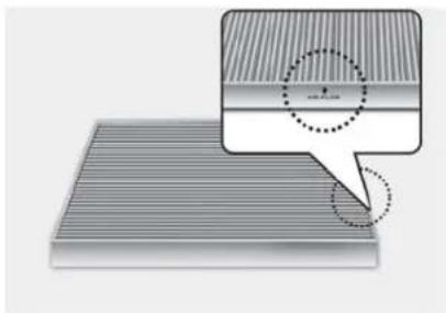
natural_image
Diagram showing a layered structure with a magnified inset highlighting a specific section (no text or symbols present)- Replace the climate control air filter.
- Reassemble in the reverse order of disassembly.
NOTICE
Install a new climate control air filter in the correct direction with the arrow symbol (↓) facing downwards, to prevent noise and reduce effectiveness.
WIPER BLADES
Blade Inspection
Contamination of either the windshield or the wiper blades with foreign matter can reduce the effectiveness of the windshield wiper functionality. Common sources of contamination are insects, tree sap, and hot wax treatments used by some commercial car washes. If the blades are not wiping properly, clean both the window and the blades with a clean cloth dampened with washer fluid.
NOTICE
To prevent damage to the wiper blades, arms or other components, do not:
- Use gasoline, kerosene, paint thinner, or other solvents on or near them.
- Attempt to move the wipers manually.
- Use non-specified wiper blades.
i Information
Commercial hot waxes applied by automatic car washes have been known to make the windshield difficult to clean.
Blade Replacement
When the wipers no longer clean adequately, the blades may be worn or cracked, and require replacement.
NOTICE
To prevent damage to the wiper arms or other components, do not attempt to move the wipers manually.
NOTICE
The use of a non-specified wiper blade could result in wiper malfunction and failure.
NOTICE
- In order to prevent damage to the hood and the wiper arms, the wiper arms should only be lifted when in the top wiping position.
• Always return the wiper arms to the windshield before driving.
Front windshield wiper service positions
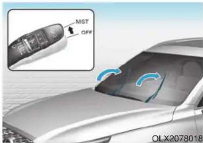
This vehicle has a "hidden" wiper design which means that the wipers cannot be lifted when they are in their bottom resting position.
- Within 20 seconds of turning off the engine, lift and hold the wiper lever up to the MIST position for about 2 seconds until the wipers move to the top wipe position.
- At this time you can lift the wipers off the windshield.
- Gently put the wipers back down onto the windshield.
- Turn the wipers to any ON position to return the wipers to the bottom resting position.
Blade replacement
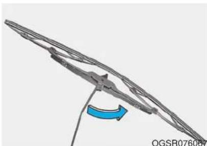
natural_image
Diagram of a mechanical or structural component with a blue curved arrow indicating direction (no text or symbols present)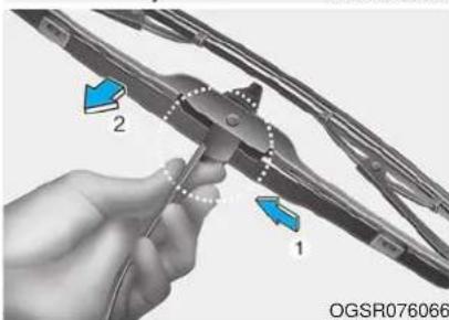
natural_image
Close-up of a hand using a tool to adjust or install a car blade, with arrows indicating direction (no text or symbols visible)- Lift up the wiper blade clip. Then lift up the wiper blade.
- While pushing the lock (1), pull down the wiper blade (2).
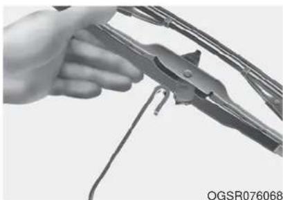
natural_image
Close-up of a hand using a pliers to cut metal wires (no text or symbols visible)- Remove the wiper blade from the wiper arm.
- Install a new wiper blade assembly in the reverse order of removal.
- Return the wiper arm on the windshield.
Rear window wiper blade
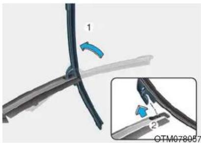
- Raise the wiper arm and then rotate the wiper blade assembly (1).
- Pull out the wiper blade assembly (2).
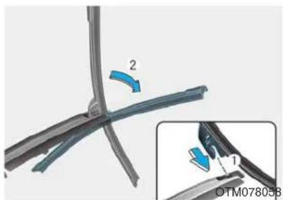
- Install the new blade assembly by inserting the center part into the slot in the wiper arm until it clicks into place (1).
- Make sure the blade assembly is installed firmly by trying to pull it slightly.
- Rotate back the blade assembly so that it aligns with the wiper arm (2).
To prevent damage to the wiper arms or other components, we recommend that the wiper blades be replaced by an authorized HYUNDAI dealer.
BATTERY
WARNING
To prevent SERIOUS INJURY or DEATH to you or bystanders, always follow these precautions when working near or handling the battery:

Always read and follow instructions carefully when handling a battery.

Wear eye protection designed to protect the eyes from acid splashes.

Keep all flames, sparks, or smoking materials away from the battery.

Hydrogen is always present in battery cells, is highly combustible, and may explode if ignited.

Keep batteries out of reach of children.

Batteries contain sulfuric acid which is highly corrosive. Do not allow acid to contact your eyes, skin or clothing.
If acid gets into your eyes, flush your eyes with clean water for at least 15 minutes and get immediate medical attention. If acid gets on your skin, thoroughly wash the area. If you feel pain or a burning sensation, get medical attention immediately.
- When lifting a plastic-cased battery, excessive pressure on the case may cause battery acid to leak. Lift with a battery carrier or with your hands on opposite corners.
-
Do not attempt to jump start your vehicle if your battery is frozen.
-
NEVER attempt to recharge the battery when the vehicle's battery cables are connected to the battery.
- The electrical ignition system works with high voltage. NEVER touch these components with the engine running or when the ignition switch is in the ON position.
WARNING
CALIFORNIA PROPOSITION 65 WARNING
Battery posts, terminals, and related accessories contain lead and lead compounds, chemicals known to the State of California to cause cancer, birth defects and reproductive harm. Batteries also contain other chemicals known to the State of California to cause cancer. Wash hands after handling.
For more information go to https://www.p65warnings.ca.gov/passenger-vehicle
NOTICE
- When you do not use the vehicle for a long time in a low temperature area, disconnect the battery and keep it indoors.
• Always charge the battery fully to prevent battery case damage in low temperature areas.
For Best Battery Service
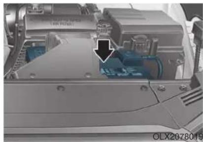
natural_image
Close-up of a mechanical device with a black arrow pointing to a component, no visible text or symbols- Keep the battery securely mounted.
- Keep the battery top clean and dry.
- Keep the terminals and connections clean, tight, and coated with petroleum jelly or terminal grease.
- Rinse any spilled acid from the battery immediately with a solution of water and baking soda.
Battery Recharging
WARNING
Always follow these instructions when recharging your vehicle's battery to avoid the risk of SERIOUS INJURY or DEATH from explosions or acid burns:
- Before performing maintenance or recharging the battery, turn off all accessories and place the ignition switch to the LOCK/OFF position.
- Keep all flames, sparks, or smoking materials away from the battery.
• Always work outdoors or in an area with plenty of ventilation. - Wear eye protection when checking the battery during charging.
-
The battery must be removed from the vehicle and placed in a well ventilated area.
-
Watch the battery during charging, and stop or reduce the charging rate if the battery cells begin boiling violently.
- The negative battery cable must be removed first and installed last when the battery is disconnected. Disconnect the battery charger in the following order:
(1)Turn off the battery charger main switch.
(2)Unhook the negative clamp from the negative battery terminal.
(3)Unhook the positive clamp from the positive battery terminal.
• Always use a genuine HYUNDAI approved battery when you replace the battery.
NOTICE
AGM battery
- Absorbent Glass Matt (AGM) batteries are maintenance-free and we recommend that the AGM battery be serviced by an authorized retailer of HYUNDAI dealer. For charging your AGM battery, use only fully automatic battery chargers that are specially developed for AGM batteries.
- When replacing the AGM battery, we recommend that you use parts for replacement from an authorized retailer of HYUNDAI dealer.
- Do not open or remove the cap on top of the battery. This may cause leaks of internal electrolyte that could result in severe injury.
By jump starting
After a jump start from a good battery, drive the vehicle for at least 30 minutes or operate at idle for at least 60 minutes before it is shutoff. Alternatively you may visit a dealer for charge and battery test.
The vehicle may not restart if you shut it off before the battery had a chance to adequately recharge. See "Jump Starting" in chapter 6 for more information on jump starting procedures.
i Information

An inappropriately disposed battery can be harmful to the environment and human health. Dispose of the battery according to your local law(s) or regulations.
Reset Features
The following items may need to be reset after the battery has been discharged or the battery has been disconnected. See chapter 3 or 4 for:
- Power Windows
- Driver Position Memory System
- Trip Computer
• Climate Control System - Clock
- Audio System
- Sunroof
TIRES AND WHEELS
WARNING
Tire failure may cause loss of vehicle control resulting in an accident. To reduce risk of SERIOUS INJURY or DEATH, take the following precautions:
- Inspect your tires monthly for proper inflation as well as wear and damage.
- The recommended cold tire pressure for your vehicle can be found in this manual and on the tire label located on the driver's side center pillar. Always use a tire pressure gauge to measure tire pressure. Tires with too much or too little pressure wear unevenly causing poor handling.
-
Check the pressure of the spare every time you check the pressure of the other tires on your vehicle.
-
Replace tires that are worn, show uneven wear, or are damaged. Worn tires can cause loss of braking effectiveness, steering control, or traction.
- ALWAYS replace tires with the same size as each tire that was originally supplied with this vehicle. Using tires and wheels other than the recommended sizes could cause unusual handling characteristics, poor vehicle control, or negatively affect your vehicle's Anti-Lock Brake System (ABS) resulting in a serious accident.
Tire Care
For proper maintenance, safety, and maximum fuel economy, you must always maintain recommended tire inflation pressures and stay within the load limits and weight distribution recommended for your vehicle.
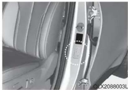
natural_image
Close-up of a car interior showing the door, seatbelt, and camera lens (no visible text or symbols)All specifications (sizes and pressures) can be found on a label attached to the driver's side center pillar.
Recommended Cold Tire Inflation Pressures
All tire pressures (including the spare) should be checked when the tires are cold. "Cold tires" means the vehicle has not been driven for at least three hours or has been driven for less than one mile (1.6 km).
Warm tires normally exceed recommended cold tire pressures by 4 to 6 psi (28 to 41 kPa). Do not release air from warm tires to adjust the pressure or the tires will be under-inflated. For recommended inflation pressure, refer to "Tire and Wheels" in chapter 8.
WARNING
Recommended pressures must be maintained for the best ride, vehicle handling, and minimum tire wear.
Over-inflation or under-inflation can reduce tire life, adversely affect vehicle handling, and lead to sudden tire failure that could result in loss of vehicle control resulting in an accident.
Severe under-inflation can lead to severe heat build-up, causing blowouts, tread separation and other tire failures that can result in the loss of vehicle control resulting in an accident. This risk is much higher on hot days and when driving for long periods at high speeds.
CAUTION
- Under-inflation results in excessive wear, poor handling and reduced fuel economy. Wheel deformation is also possible. Keep your tire pressures at the proper levels. If a tire frequently needs refilling, have it checked by an authorized HYUNDAI dealer.
• Over-inflation produces a harsh ride, excessive wear at the center of the tire tread, and a greater possibility of damage from road hazards.
Check Tire Inflation Pressure
Check your tires, including the spare tire, once a month or more.
How to check
Use a good quality tire pressure gauge to check tire pressure. You can not tell if your tires are properly inflated simply by looking at them. Radial tires may look properly inflated when they are under-inflated.
Remove the valve cap from the tire valve stem. Press the tire gauge firmly onto the valve to get a pressure measurement. If the cold tire inflation pressure matches the recommended pressure on the tire label located on the driver's side center pillar or in this manual. No further adjustment is necessary. If the pressure is low, add air until you reach the recommended pressure. Make sure to put the valve caps back on the valve stems. Without the valve cap, dirt or moisture could get into the valve core and cause air leakage. If a valve cap is missing, install a new one as soon as possible.
If you overfill the tire, release air by pushing on the metal stem in the center of the tire valve. Recheck the tire pressure with the tire gauge. Be sure to put the valve caps back on the valve stems. Without the valve cap, dirt or moisture could get into the valve core and cause air leakage. If a valve cap is missing, install a new one as soon as possible.
A cold tire means the vehicle has been sitting for 3 hours and driven for less than 1 mile (1.6 km) in that 3 hour period.
Allow the tire to cool before measuring the inflation pressure. Always be sure the tire is cold before inflating to the recommended pressure.
Tire Rotation
To equalize tread wear, HYUNDAI recommends that the tires be rotated according to the maintenance schedule or sooner if irregular wear develops.
During rotation, check the tires for correct balance.
When rotating tires, check for uneven wear and damage. Abnormal wear is usually caused by incorrect tire pressure, improper wheel alignment, out-of-balance wheels, severe braking or severe cornering. Look for bumps or bulges in the tread or side of the tire. Replace the tire if you find any of these conditions. Replace the tire if fabric or cord is visible. After rotation, be sure to bring the front and rear tire pressures to specification and check lug nut tightness (proper torque is 79\~94 lbf·ft [11\~13 kgf·m]).
■Without a spare tire
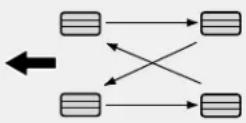
S2BLA790A
■Directional tires (if equipped)
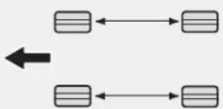
CBGQ0707A
Disc brake pads should be inspected for wear whenever tires are rotated.
i Information
Tires that are asymmetrical or directional can only be installed on the wheel in one direction. The outside and inside of an asymmetrical tire is not easily distinguishable. Pay careful attention to the markings on the sidewalls of the tires, noting the "outside" marking and also the rotating direction before installing them on the vehicle.
WARNING
- Do not use the compact spare tire for tire rotation.
- Do not mix bias ply and radial ply tires under any circumstances. This may cause unusual handling characteristics that may cause loss of vehicle control resulting in an accident.
Wheel Alignment and Tire Balance
The wheels on your vehicle were aligned and balanced carefully at the factory to give you the longest tire life and best overall performance.
In most cases, you will not need to have your wheels aligned again. However, if you notice unusual tire wear or your vehicle pulling one way or the other, the alignment may need to be reset.
If you notice your vehicle vibrating when driving on a smooth road, your wheels may need to be rebalanced.
NOTICE
Improper wheel weights can damage your vehicle's aluminum wheels. Use only approved wheel weights.
Tire Replacement
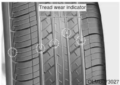
If the tire is worn evenly, a tread wear indicator will appear as a solid band across the tread. This shows there is less than 2/32 inch (1.6 mm) of tread left on the tire. Replace the tire when this happens.
Do not wait for the tread surface to become level with the tread wear indicators before replacing the tire.
CAUTION
When replacing the tires, recheck and tighten the wheel nuts after driving about 600 miles (1,000 km). If the steering wheel shakes or the vehicle vibrates while driving, the tire is out of balance. Align the tire balance. If the problem is not solved, contact an authorized HYUNDAI dealer.
WARNING
To reduce the risk of DEATH or SERIOUS INJURY:
- Replace tires that are worn, show uneven wear, or are damaged. Worn tires can cause loss of braking effectiveness, steering control, and traction.
-
Always replace tires with the same size as each tire that was originally supplied with this vehicle. Using tires and wheels other than the recommended sizes could cause unusual handling characteristics, poor vehicle control, or negatively affect your vehicle's Anti-Lock Brake System (ABS) resulting in a serious accident.
-
Tires degrade over time, even when they are not being used. Regardless of the remaining tread, HYUNDAI recommends that tires be replaced after six (6) years of normal service.
- When replacing tires (or wheels), it is recommended to replace the two front or two rear tires (or wheels) as a pair. Replacing just one tire can seriously affect your vehicle's handling. If only replacing one pair of tires, it is recommended to install the pair of new tires on the rear axle.
- Heat caused by hot climates or frequent high loading conditions can accelerate the aging process. Failure to follow this warning may cause sudden tire failure, which could lead to a loss of vehicle control resulting in an accident.
Compact spare tire replacement
A compact spare tire has a shorter tread life than a regular size tire. Replace it when you can see the tread wear indicator bars on the tire. The replacement compact spare tire should be the same size and design tire as the one provided with your new vehicle and should be mounted on the same compact spare tire wheel. The compact spare tire is not designed to be mounted on a regular size wheel, and the compact spare tire wheel is not designed for mounting a regular size tire.
WARNING
The original tire should be repaired or replaced as soon as possible to avoid failure of the spare and loss of vehicle control resulting in an accident. The compact spare tire is for emergency use only. Do not operate your vehicle over 50 mph (80 km/h) when using the compact spare tire.
Wheel Replacement
When replacing the metal wheels for any reason, make sure the new wheels are equivalent to the original factory units in diameter, rim width and offset.
Tire Traction
Tire traction can be reduced if you drive on worn tires, tires that are improperly inflated or on slippery road surfaces. Tires should be replaced when the tread depth is at least 2/32 inch (1.6 mm). To reduce the possibility of losing control, slow down whenever there is rain, snow or ice on the road.
Tire Maintenance
In addition to proper inflation, correct wheel alignment helps to decrease tire wear. If you find a tire is worn unevenly, have your dealer check the wheel alignment.
When you have new tires installed, make sure they are balanced. This will increase vehicle ride comfort and tire life. Additionally, a tire should always be rebalanced if it is removed from the wheel.
Tire Sidewall Labeling
This information identifies and describes the fundamental characteristics of the tire and also provides the tire identification number (TIN) for safety standard certification. The TIN can be used to identify the tire in case of a recall.
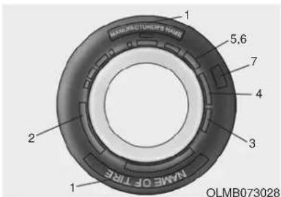
1. Manufacturer or brand name
Manufacturer or brand name is shown.
2. Tire size designation
A tire's sidewall is marked with a tire size designation. You will need this information when selecting replacement tires for your car. The following explains what the letters and numbers in the tire size designation mean.
Example tire size designation: (These numbers are provided as an example only; your tire size designator could vary depending on your vehicle.)
245/60R18 105H
245 - Tire width in millimeters.
60 - Aspect ratio. The tire's section height as a percentage of its width.
R - Tire construction code (Radial).
18 - Rim diameter in inches.
105 - Load Index, a numerical code associated with the maximum load the tire can carry.
H - Speed Rating Symbol. See the speed rating chart in this section for additional information.
Wheel size designation
Wheels are also marked with important information that you need if you ever have to replace one. The following explains what the letters and numbers in the wheel size designation mean.
Example wheel size designation:
7.5J x 18
7.5 - Rim width in inches.
J - Rim contour designation.
18 - Rim diameter in inches.
Tire speed ratings
The chart below lists many of the different speed ratings currently being used for passenger vehicle tires. The speed rating is part of the tire size designation on the sidewall of the tire. This symbol corresponds to that tire's designed maximum safe operating speed.
| Speed Rating Symbol | Maximum Speed |
| S 112 | mph (180 km/h) |
| T 118 | mph (190 km/h) |
| H 130 | mph (210 km/h) |
| V 149 | mph (240 km/h) |
| W 168 | mph (270 km/h) |
| Y 186 | mph (300 km/h) |
3. Checking tire life (TIN : Tire Identification Number)
Any tires that are over six years old, based on the manufacturing date, (including the spare tire) should be replaced by new ones. You can find the manufacturing date on the tire sidewall (possibly on the inside of the wheel), displaying the DOT Code. The DOT Code is a series of numbers on a tire consisting of numbers and English letters. The manufacturing date is designated by the last four digits (characters) of the DOT code.
The front part of the DOT shows a plant code number, tire size and tread pattern and the last four numbers indicate week and year manufactured.
For example:
DOT XXXX XXXX 1419 represents that the tire was produced in the 14th week of 2019.
4. Tire ply composition and material
The number of layers or plies of rubber-coated fabric in the tire. Tire manufacturers also must indicate the materials in the tire, which include steel, nylon, polyester, and others. The letter "R" means radial ply construction; the letter "D" means diagonal or bias ply construction; and the letter "B" means belted-bias ply construction.
5. Maximum permissible inflation pressure
This number is the greatest amount of air pressure that should be put in the tire. Do not exceed the maximum permissible inflation pressure. Refer to the Tire and Loading Information label for recommended inflation pressure.
6. Maximum load rating
This number indicates the maximum load in kilograms and pounds that can be carried by the tire. When replacing the tires on the vehicle, always use a tire that has the same load rating as the factory installed tire.
7. Uniform tire quality grading
Quality grades can be found where applicable on the tire sidewall between tread shoulder and maximum section width.
For example:
TREAD WEAR 200
TRACTION AA
TEMPERATURE A
Tread wear
The tread wear grade is a comparative rating based on the wear rate of the tire when tested under controlled conditions on a specified government test course. For example, a tire graded 150 would wear one-and-a-half times (1½) as well on the government course as a tire graded 100.
The relative performance of tires depends upon the actual conditions of their use, however, and may depart significantly from the norm due to variations in driving habits, service practices and differences in road characteristics and climate.
These grades are molded on the sidewalls of passenger vehicle tires. The tires available as standard or optional equipment on your vehicle may vary with respect to grade.
Traction - AA, A, B & C
The traction grades, from highest to lowest, are AA, A, B and C. Those grades represent the tire's ability to stop on wet pavement as measured under controlled conditions on specified government test surfaces of asphalt and concrete. A tire marked C may have poor traction performance.
WARNING
The traction grade assigned to this tire is based on straight-ahead braking traction tests, and does not include acceleration, cornering, hydroplaning, or peak traction characteristics.
Temperature - A, B & C
The temperature grades are A (the highest), B and C representing the tire's resistance to the generation of heat and its ability to dissipate heat when tested under controlled conditions on a specified indoor laboratory test wheel.
Sustained high temperature can cause the material of the tire to degenerate and reduce tire life, and excessive temperature can lead to sudden tire failure. Grade C responds to a level of performance which all passenger car tires must meet under the Federal Motor Vehicle Safety Standard No. 109. Grades B and A represent higher levels of performance on the laboratory test wheel than the minimum required by law.
WARNING
The temperature grade for this tire is established for a tire that is properly inflated and not overloaded. Excessive speed, under-inflation, over-inflation, or excessive loading, either separately or in combination, can cause heat build-up and possible sudden tire failure. This may cause loss of vehicle control resulting in an accident.
Tire Terminology and Definitions
Air Pressure
The amount of air inside the tire pressing outward on the tire. Air pressure is expressed in pounds per square inch (psi) or kilopascal (kPa).
Accessory Weight
This means the combined weight of optional accessories. Some examples of optional accessories are automatic transmission, power seats, and air conditioning.
Aspect Ratio
The relationship of a tire's height to its width.
Belt
A rubber coated layer of cords that is located between the plies and the tread. Cords may be made from steel or other reinforcing materials.
Bead
The tire bead contains steel wires wrapped by steel cords that hold the tire onto the rim.
Bias Ply Tire
A pneumatic tire in which the plies are laid at alternate angles less than 90 degrees to the centerline of the tread.
Cold Tire Pressure
The amount of air pressure in a tire, measured in pounds per square inch (psi) or kilopascals (kPa) before a tire has built up heat from driving.
Curb Weight
This means the weight of a motor vehicle with standard and optional equipment including the maximum capacity of fuel, oil and coolant, but without passengers and cargo.
DOT Markings
A code molded into the sidewall of a tire signifying that the tire is in compliance with the U.S. Department of Transportation motor vehicle safety standards. The DOT code includes the Tire Identification Number (TIN), an alphanumeric designator which can also identify the tire manufacturer, production plant, brand and date of production.
GVWR
Gross Vehicle Weight Rating
GAWR FRT
Gross Axle Weight Rating for the Front Axle.
GAWR RR
Gross Axle Weight Rating for the Rear axle.
Intended Outboard Sidewall
The side of an asymmetrical tire, that must always face outward when mounted on a vehicle.
Kilopascal (kPa)
The metric unit for air pressure.
Light truck(LT) tire
A tire designated by its manufacturer as primarily intended for use on lightweight trucks or multipurpose passenger vehicles.
Load ratings
The maximum load that a tire is rated to carry for a given inflation pressure.
Load Index
An assigned number ranging from 1 to 279 that corresponds to the load carrying capacity of a tire.
Maximum Inflation Pressure
The maximum air pressure to which a cold tire may be inflated. The maximum air pressure is molded onto the sidewall.
Maximum Load Rating
The load rating for a tire at the maximum permissible inflation pressure for that tire.
Maximum Loaded Vehicle Weight
The sum of curb weight; accessory weight; vehicle capacity weight; and production options weight.
Normal Occupant Weight
The number of occupants a vehicle is designed to seat multiplied by 150 pounds (68 kg).
Occupant Distribution
Designated seating positions.
Outward Facing Sidewall
An asymmetrical tire has a particular side that faces outward when mounted on a vehicle. The outward facing sidewall bears white lettering or bears manufacturer, brand, and/or model name molding that is higher or deeper than the same moldings on the inner facing sidewall.
Passenger (P-Metric) tire
A tire used on passenger cars and some light duty trucks and multipurpose vehicles.
Ply
A layer of rubber-coated parallel cords.
Pneumatic tire
A mechanical device made of rubber, chemicals, fabric and steel or other materials, that, when mounted on an automotive wheel provides the traction and contains the gas or fluid that sustains the load.
Pneumatic options weight
The combined weight of installed regular production options weighing over 5 lb. (2.3 kg) in excess of the standard items which they replace, not previously considered in curb weight or accessory weight, including heavy duty breaks, ride levelers, roof rack, heavy duty battery, and special trim.
Recommended Inflation Pressure
Vehicle manufacturer's recommended tire inflation pressure as shown on the tire placard.
Radial Ply Tire
A pneumatic tire in which the ply cords that extend to the beads are laid at 90 degrees to the centerline of the tread.
Rim
A metal support for a tire and upon which the tire beads are seated.
Sidewall
The portion of a tire between the tread and the bead.
Speed Rating
An alphanumeric code assigned to a tire indicating the maximum speed at which a tire can operate.
Traction
The friction between the tire and the road surface. The amount of grip provided.
Tread
The portion of a tire that comes into contact with the road.
Treadwear Indicators
Narrow bands, sometimes called "wear bars", that show across the tread of a tire when only 1/16 inch of tread remains.
UTQGS
Uniform Tire Quality Grading Standards is a tire information system that provides consumers with ratings for a tire's traction, temperature and treadwear. Ratings are determined by tire manufacturers using government testing procedures. The ratings are molded into the sidewall of the tire.
Vehicle Capacity Weight
The number of designated seating positions multiplied by 150 lbs. (68 kg) plus the rated cargo and luggage load.
Vehicle Maximum Load on the Tire
Load on an individual tire due to curb and accessory weight plus maximum occupant and cargo weight.
Vehicle Normal Load on the Tire Load on an individual tire that is determined by distributing to each axle its share of the curb weight, accessory weight, and normal occupant weight and dividing by 2.
Vehicle Placard
A label permanently attached to a vehicle showing the original equipment tire size and recommended inflation pressure.
All Season Tires
HYUNDAI specifies all season tires on some models to provide good performance for use all year round, including snowy road conditions. All season tires are identified by ALL SEASON and/or M+S (Mud and Snow) on the tire sidewall. Snow tires have better snow traction than all season tires and may be more appropriate in some areas.
Snow Tires
If you equip your car with snow tires, they should be the same size and have the same load capacity as the original tires. Snow tires should be installed on all four wheels; otherwise, poor handling may result. Snow tires should carry 4 psi (28 kPa) more air pressure than the pressure recommended for the standard tires on the tire label on the driver's side of the center pillar, or up to the maximum pressure shown on the tire sidewall, whichever is less. Do not drive faster than 75 mph (120 km/h) when your vehicle is equipped with snow tires.
Radial-Ply Tires
Radial-ply tires provide improved tread life, road hazard resistance and smoother high speed ride. The radial-ply tires used on this vehicle are of belted construction, and are selected to complement the ride and handling characteristics of your vehicle.
Radial-ply tires have the same load carrying capacity, as bias-ply or bias belted tires of the same size, and use the same recommended inflation pressure. Mixing of radial-ply tires with bias-ply or bias belted tires is not recommended. Any combinations of radial-ply and bias-ply or bias belted tires when used on the same vehicle will seriously deteriorate vehicle handling. The best rule to follow is: Identical pairs of radial-ply tires should always be used as a set for the front tires and a set for the rear tires.
Longer wearing tires can be more susceptible to irregular tread wear. It is very important to follow the tire rotation interval in this chapter to achieve the tread life potential of these tires. Cuts and punctures in radial-ply tires are repairable only in the tread area, because of sidewall flexing. Consult your tire dealer for radial-ply tire repairs.
WARNING
Do not mix bias ply and radial ply tires under any circumstances. This may cause unusual handling characteristics that may cause loss of vehicle control resulting in an accident.
CAUTION
- When driving on a rough road or off road, drive cautiously because tires and wheels may be damaged. And after driving, inspect tires and wheels.
- When passing over a pothole, speed bump, manhole, or curb stone, drive slowly so that the tires and wheels are not damaged.
- If the tire is subjected to a severe impact, have the tire and wheel inspected by an authorized HYUNDAI dealer.
- It is not easy to recognize tire damage with your own eyes. But if there is the slightest hint of tire damage, have the tire checked or replaced because the tire damage may cause air leakage from the tire.
- If the tire is damaged by driving on a rough road, off road, pothole, manhole, or curb stone, it will not be covered by the warranty.
FUSES
■Blade type
Normal
Blown
■Cartridge type
Normal
Blown
■Multi fuse
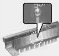
Normal
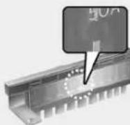
Blown
OTM078035
A vehicle's electrical system is protected from electrical overload damage by fuses.
This vehicle has 2 (or 3) fuse panels, one located in the driver's side panel bolster, the other in the engine compartment near the battery.
If any of your vehicle's lights, accessories, or controls do not work, check the appropriate circuit fuse. If a fuse has blown, the element inside the fuse will be melted or broken.
If the electrical system does not work, first check the driver's side fuse panel. Before replacing a blown fuse, turn the engine and all switches off, and then disconnect the negative battery cable. Always replace a blown fuse with one of the same rating.
If the replacement fuse blows, this indicates an electrical problem. Avoid using the system involved and immediately consult an authorized HYUNDAI dealer.

WARNING
NEVER replace a fuse with anything but another fuse of the same rating.
• A higher capacity fuse could cause damage and possibly cause a fire.
- Do not install a wire or aluminum foil instead of the proper fuse - even as a temporary repair. It may cause extensive wiring damage and possibly a fire.
NOTICE
Do not use a screwdriver or any other metal object to remove fuses because it may cause a short circuit and damage the system.
Instrument Panel Fuse Replacement
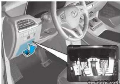
natural_image
Interior view of a car dashboard and steering wheel, showing the dashboard with a blue arrow pointing to the left side of the dashboard (no visible text or symbols)- Turn the engine off.
- Turn all other switches OFF.
- Open the fuse panel cover.
- Refer to the label on the inside of the fuse panel cover to locate the suspected fuse location.
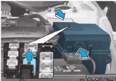
- Pull the suspected fuse straight out. Use the removal tool provided in the engine compartment fuse panel cover.
- Check the removed fuse; replace it if it is blown. Spare fuses are provided in the instrument panel fuse panels (or in the engine compartment fuse panel).
- Push in a new fuse of the same rating, and make sure it fits tightly in the clips. If it fits loosely, consult an authorized HYUNDAI dealer.
In an emergency, if you do not have a spare fuse, use a fuse of the same rating from a circuit you may not need for operating the vehicle.
If the headlamps or other electrical components do not work and the fuses are undamaged, check the fuse panel in the engine compartment. If a fuse is blown, it must be replaced with the same rating.
Engine Compartment Panel Fuse Replacement
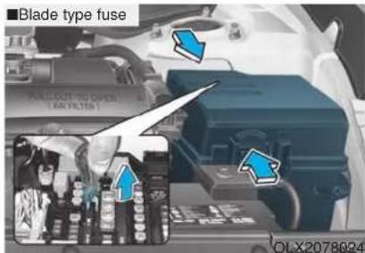
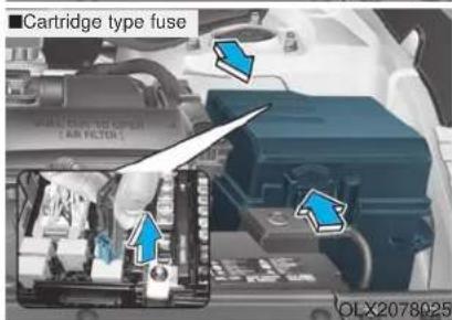
- Turn the engine off.
-
Turn all other switches OFF.
-
Remove the fuse panel cover by pressing the tap and pulling up.
- Check the removed fuse; replace it if it is blown. To remove or insert the fuse, use the fuse puller in the engine compartment fuse panel.
- Push in a new fuse of the same rating, and make sure it fits tightly in the clips. If it fits loosely, consult an authorized HYUNDAI dealer.
CAUTION
After checking the fuse box in the engine compartment securely close the fuse box cover inside the engine compartment, until it clicks.
If the fuse box is not closed properly, water may leak in side, possibly causing a malfunction with the electrical system.
Multi fuse
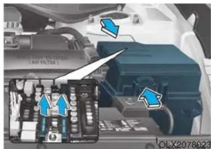
If the multi fuse is blown, it must be removed as follows:
- Turn off the engine.
- Disconnect the negative battery cable.
- Remove the fuse panel cover by pressing the tab and pulling it up.
- Remove the nuts shown in the picture above.
- Replace the fuse with a new one of the same rating.
- Reinstall in the reverse order of removal.
i Information
If the multi fuse is blown, consult an authorized HYUNDAI dealer.
Fuse/Relay Panel Description
Instrument panel fuse panel
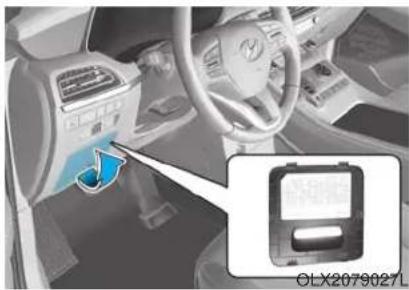
natural_image
Interior view of a car showing the dashboard and steering wheel, with a close-up inset of a battery pack (no text or symbols visible)Inside the fuse/relay box cover, you can find the fuse/relay label describing fuse/relay names and ratings.
i Information
Not all fuse panel descriptions in this manual may be applicable to your vehicle; the information is accurate at the time of printing. When you inspect the fuse box on your vehicle, refer to the fuse box label.
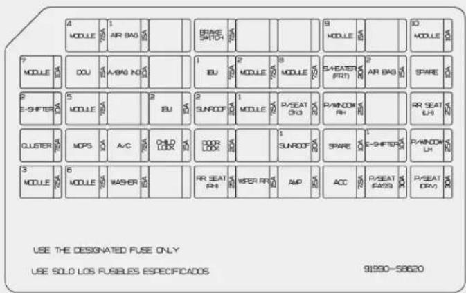
OLX2079054N
Instrument panel fuse panel
| Fuse Name Fuse Rating Protected Component | ||
| MODULE 4 | 7.5A | Data Link Connector, Stop Lamp Switch, Driver Door Module |
| AIR BAG 1 15A SRS Control Module, Passenger Occupant Detection Sensor | ||
| BRAKE SWITCH | 7.5A IBU, Stop Lamp Switch | |
| MODULE 9 15A | Front A/C Control Module, Low DC-DC Converter (Audio), Power Tail Gate Unit, Driver IMS Control Module, Head-up Display, Driver Door Module, Driver/Passenger Power Outside Mirror, Security Indicator, Rain Sensor, Rear Occupant Alert (ROA) Sensor, 3RD Seat Folding Control Module | |
| MODULE 10 10A | Blind-Spot Collision Warning Unit LH/RH, Front Console Switch, Rear A/C Control Module, Electro Chromic Mirror, Data Link Connector, Front Wireless Charger | |
| AIR BAG IND 10A Seat Belt Indicator, Instrument Cluster | ||
| IBU 1 7.5A IBU | ||
| MODULE 2 7.5A | 1ST Seat Warmer Control Module, 1ST Air Ventilation Seat Control Module, 2ND Air Ventilation Seat LH/RH Control Module, 2ND Seat LH/RH Warmer Control Module, 3RD Seat Folding Control Module, AC Inverter Outlet, Inverter Unit, Surround View Monitor Unit | |
| MODULE 8 7.5A | Driver/Passenger Smart Key Outside Handle, Driver/Passenger Outside Mirror, Key Solenoid, Center Fascia Keyboard (Hazard Switch) | |
| S/HEATER FRT | 20A 1ST Air Ventilation Control Module, 1ST Seat Warmer Control Module | |
| AIR BAG 2 15A SRS Control Module | ||
| E-SHIFTER 2 10A Electronic ATM Shift Lever Switch (SBW), SCU | ||
Instrument panel fuse panel
| Fuse Name | Fuse Rating | Protected Component |
| MODULE 5 7.5A | Crash Pad Switch, IBU, Smart Cruise Control Radar, 4WD ECM, Front Console Switch, Lane Keeping Assist Unit (Line) | |
| IBU 2 15A | IBU, Ignition Switch | |
| SUNROOF 2 | 20A Panoramic Sunroof | |
| MODULE 1 7.5A | IBU | |
| P/SEAT (3rd) | 20A 3RD Seat Folding Control Module | |
| P/WINDOW RH | 25A Passenger Safety Power Window Module, Rear Power Window Switch RH | |
| RR SEAT (LH) | 25A | 2ND Air Ventilation Seat LH Control Module, 2ND Seat LH Warmer, Control Module, 2ND Seat LH Reclining Folding Actuator |
| CLUSTER 7.5A Instrument Cluster, Head Up Display | ||
| MDPS 10A | MDPS Unit | |
| A/C | 7.5A | E/R Junction Block (Blower FRT Relay, Blower RR Relay, PTC Heater 1/2 Relay), Front A/C Control Module |
| CHILD LOCK | 15A ICM Relay Box (Child Lock/Unlock Relay) | |
| DOOR LOCK | 20A | Door Lock Relay, Door Unlock Relay, Liftgate Relay, Two Turn Unlock Relay |
Instrument panel fuse panel
| Fuse Name | Fuse Rating | Projected Component |
| SUNROOF 1 | 20A Sunroof | |
| E-SHIFTER 1 | 10A | Electronic ATM Shift Lever Switch (SBW), SCU, E/R Junction Block (FUSE -E-SHIFTER 2) |
| P/WINDOW LH | 25A Driver | Safety Power Window Module, Rear Power Window Switch LH |
| MODULE 3 | 7.5A IBU | |
| MODULE 6 | 7.5A | Audio, A/V & Navigation Head Unit, Low DC-DC Converter (Audio/AMP), Front/Rear A/C Control ModuleDriver IMS Control Module, Electro Chromic Mirror, Center Facia Keyboard, 1ST Air Ventilation Seat Control Module, 1ST Seat Warmer Control Module, 2ND Air Ventilation Seat LH/RH Control Module, 2ND Seat LH/RH Warmer Control Module, 3RD Seat Folding Control Module |
| WASHER 15 | Multifunction | Switch |
| RR SEAT (RH) | 25A | 2ND Air Ventilation Seat Control Module, 2ND Seat RH Warmer Control Module, 2ND Seat RH Reclining Folding Actuator |
| WIPER (REAR) | 15A Rear | Wiper Relay, Rear Wiper Motor |
| AMP 25A | AMP, Low DC-DC | Converter (AMP) |
| ACC 7.5A | IBU, Low DC-DC | Converter (Audio/AMP) |
| P/SEAT (PASS) | 30A Passenger | Seat Manual Switch |
| P/SEAT (DRV) | 30A Driver IMS | Control Module, Driver Seat Manual Switch |
Engine compartment fuse panel
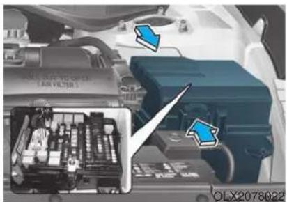
natural_image
Close-up of a car engine bay with internal components and blue arrows pointing to specific parts (no readable text or symbols)Inside the fuse/relay box cover, you can find the fuse/relay label describing fuse/relay names and ratings.
i Information
Not all fuse panel descriptions in this manual may be applicable to your vehicle; the information is accurate at the time of printing. When you inspect the fuse panel in your vehicle, refer to the fuse panel label.
USE THE DESIGNATED FUSE AND RELAY ONLY
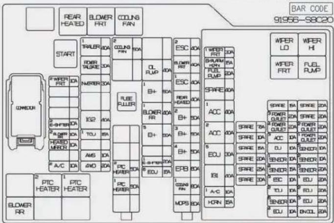
OLX2079055N
Engine compartment fuse panel
| Fuse Name Fuse Rating | Protected Component | ||
| MULTI FUSE (10P) | MDPS 80A MDPS Unit | ||
| COOLING FAN 1 80A Cooling Fan | Relay (600W) | ||
| EPB 60A ESC Module | |||
| B+4 50A | ICU Junction Block (Fuse - MODULE 8, S/HEATER FRT, P/WINDOW RH, AMP, SUN-ROOF) | ||
| B+3 50A | ICU Junction Block (Fuse - P/WINDOW LH, RR SEAT (LH), P/SEAT (DRV), P/SEAT (PASS)) | ||
| B+2 50A ICU Junction Block | (IPS 8/IPS 10/IPS 11/IPS 12/IPS 13/IPS 14/IPS 15) | ||
| REAR HEATED 40A Rear Heated | Relay | ||
| ESC 1 40A ESC Module | |||
| BLOWER 40A Blower Relay | |||
| ESC 2 40A ESC Module | |||
| MULTI FUSE (2P) | PTC HEATER 1 50A PTC Heater 1 | Relay | |
| PTC HEATER 2 50A PTC Heater 2 | Relay | ||
Engine compartment fuse panel
| Fuse Name Fuse Rating | Protected Component | ||
| FUSE | B+1 50A | ICU Junction Block (IPS 1/IPS 2/IPS 3/IPS 5/IPS 6/IPS 7, Long/Short Term Load Latch Relay) | |
| B+5 50A | ICU Junction Block (Fuse - DOOR LOCK, IBU 1, IBU 2, BRAKE SWITCH, CHILD LOCK, RR SEAT (RH), SUNROOF 2) | ||
| INVERTER 30A | AC Inverter Unit | ||
| POWER LIFTGATE | 30A Power Tail | Gate Module | |
| TRAILER 1 40A | Trailer Lamp | ||
| IG2 40A | Start Relay, ICU Junction Block (Fuse - A/C, WASHER, WIPER (REAR), MODULE 1, MODULE 2, REAR A/C) | ||
| OIL PUMP 40A | Electronic Oil Pump Module | ||
| COOLING FAN 2 50A | Cooling Fan | Relay | |
| HEATED MIRROR | 10A | Driver/Passenger Power Outside Mirror, A/C Control Module | |
| A/C 2 10A A/C | Control Module | ||
| WIPER FRT 2 10A | Wiper (LO) Relay, Front Wiper Motor | ||
| ECU 6 | 15A PCM | ||
Engine compartment fuse panel
| Fuse Name Fuse Rating | Protected Component | |
| FUSE | AMS 10A Battery Sensor | |
| E-SHIFTER 1 20A Electronic Transmission | ||
| 4WD 20A AWD ECM | ||
| E-SHIFTER2 10A Electronic Transmission | ||
| BLOWER 2 10A A/C Control Module | ||
| BLOWER 1 40A Rear Blower Relay | ||
| TCU 1 15A Transmission Range Switch | ||
| PCB Block | SENSOR 6 15A Glow Relay Unit | |
| ECU 3 10A ESC Module | ||
| ICU 10A ICU Junction Block | ||
| SENSOR 5 10A Oxygen Sensor Up #1/#2 | ||
| IGN COIL 20A Ignition Coil #1/#2/#3/#4/#5/#6 | ||
Engine compartment fuse panel
| Fuse Name Fuse Rating | Protected Component | |
| PCB Block | SENSOR 1 10A | Fuel Pump Relay |
| A/C 1 10A [2.4 GDI] A/CON Relay | ||
| WIPER FRT 1 30A Wiper Main Relay | ||
| TCU 2 10A TCM, SBW Controller | ||
| ECU 3 20A PCM | ||
| B/ALARM HORN 15A Burglar Alarm | Horn Relay | |
| HORN 15A Horn Relay | ||
| FUEL PUMP 20A Fuel Pump Relay | ||
| ECU 1 20A PCM | ||
| SENSOR 2 10A | ||
| ECU 2 20A PCM | ||
| POWER OUTLET 1 20A Rear Power | Outlet 1 | |
Engine compartment fuse panel
| Fuse Name Fuse Rating | Protected Component | |
| PCB Block | POWER OUTLET 2 | 20A Rear Power Outlet 2 |
| ACC 3 10A ICU Junction Block (Fuse - ACC) | ||
| ECU 4 10A PCM | ||
| IG 1 40A PDM (IG1) Relay | ||
| ACC 1 40A ACC 1 Relay | ||
| ACC 2 40A ACC 2 Relay | ||
| ECU 5 30A Main Relay | ||
| POWER OUTLET 3 | 20A Luggage Power Outlet | |
| POWER OUTLET 4 | 20A Front Power Outlet | |
| SENSOR 4 15A | Ignition Coil #1/#2/#3/#4/#5/#6, Cooling Fan Controller | |
LIGHT BULBS
Consult an authorized HYUNDAI dealer to replace most vehicle light bulbs. It is difficult to replace vehicle light bulbs because other parts of the vehicle must be removed before you can get to the bulb. This is especially true for removing the headlamp assembly to get to the bulb(s).
Removing/installing the headlamp assembly can result in damage to the vehicle.
i Information
After heavy driving, rain or washing, headlamp and trunk lenses could appear frosty. This condition is caused by the temperature difference between the lamp inside and the outside temperature. This is similar to the condensation on your windows inside your vehicle during the rain and doesn't indicate a problem with your vehicle. If the water leaks into the lamp bulb circuitry, have your vehicle checked by an authorized HYUNDAI dealer.
WARNING
- Prior to replacing a lamp, depress the brake pedal, move the shift button into P (Park) apply the parking brake, place the ignition switch to the OFF position, and take the key with you when leaving the vehicle to avoid sudden movement of the vehicle and to prevent possible electric shock.
- Be aware the bulbs may be hot and may burn your fingers.
Headlamp, Parking lamp, Daytime Running Light, Turn signal lamp and Side marker
Type A
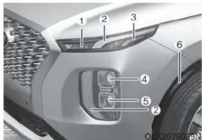
(1) Turn signal lamp
(2) Daytime running light / Parking lamp
(3) Side marker lamp
(4) Headlamp (Low)
(5) Headlamp (High)
(6) Side reflex reflector
Daytime running light (DRL), parking lamp, turn signal lamp and side marker lamp
If the LED lamp does not operate, have the system checked by an authorized HYUNDAI dealer.
The LED lamps cannot be replaced as a single unit because it is an integrated unit. The LED lamps has to be replaced with the unit.
A skilled technician should check or repair the LED lamp, for it may damage related parts of the vehicle.
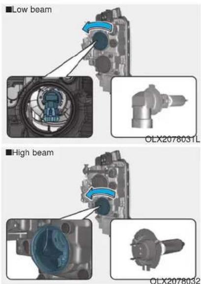
Headlamp
- Open the hood.
-
Disconnect the negative battery cable.
-
Remove the headlamp bulb cover by turning it counterclockwise.
- Disconnect the headlamp bulb socket-connector.
- Remove the bulb socket from the headlamp assembly by turning it counterclockwise.
- Install a new headlamp bulb.
- Connect the headlamp bulb socket-connector.
- Install the headlamp bulb cover by turning it clockwise.
i Information
The headlamp aiming should be adjusted after an accident or after the headlamp assembly is reinstalled at an authorized HYUNDAI dealer.
WARNING
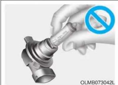
natural_image
Hand holding a mechanical component with a blue prohibition symbol (no text or labels on the diagram itself)- Handle halogen bulbs with care. Halogen bulbs contain pressurized gas that will produce flying pieces of glass that could cause injuries if broken.
- Wear eye protection when changing a bulb. Allow the bulb to cool down before handling it.
• Always handle them carefully, and avoid scratches and abrasions. If the bulbs are lit, avoid contact with liquids.
- Never touch the glass with bare hands. Residual oil may cause the bulb to overheat and burst when lit.
- A bulb should be operated only when installed in a headlamp.
- If a bulb becomes damaged or cracked, replace it immediately and carefully dispose of it.
Type B
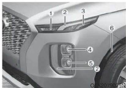
(1) Turn signal lamp
(2) Daytime running light / Parking lamp
(3) Side marker lamp
(4) Headlamp (Low/High)
(5) Headlamp (High)
(6) Side reflex reflector
Headlamp, parking lamp, daytime running light, turn signal lamp and side marker lamp
If the LED lamp does not operate, have the system checked by an authorized HYUNDAI dealer.
The LED lamps cannot be replaced as a single unit because it is an integrated unit. The LED lamps has to be replaced with the unit.
A skilled technician should check or repair the LED lamp, for it may damage related parts of the vehicle.
Side Repeater Lamp Replacement
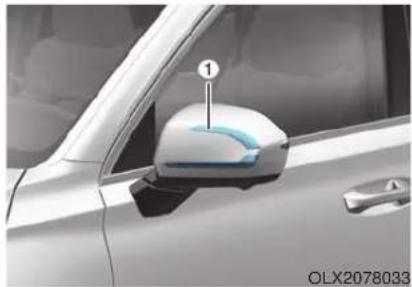
natural_image
Close-up of a car's side mirror with a numbered label pointing to the front wheel (no text or symbols on the mirror itself)If the LED lamp (1) does not operate, have the system checked by an authorized HYUNDAI dealer.
The LED lamps cannot be replaced as a single unit because it is an integrated unit. The LED lamps has to be replaced with the unit.
A skilled technician should check or repair the LED lamp, for it may damage related parts of the vehicle.
Rear combination lamp light replacement
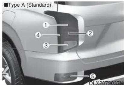
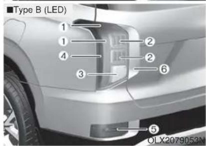
Type A
(1) Tail lamp
(2) Tail/Stop lamp
(3) Turn signal lamp
(4) Side marker lamp
(5) Backup lamp
Type B
(1) Tail lamp, Side marker
(2) Stop lamp
(3) Turn signal lamp
(4) Side marker lamp
(5) Backup lamp
(6) Garnish lamp
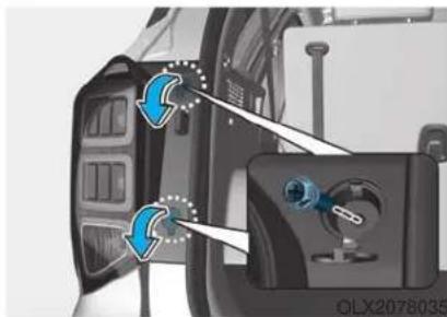
natural_image
Close-up of a mechanical component with blue arrows indicating direction, no visible text or symbolsOLX2078036
Stop/Tail lamp and turn signal lamp (Type A)
- Turn off the engine.
- Open the liftgate.
- Loosen the lamp assembly retaining screws with a cross-tip screw-driver.
- Remove the rear combination lamp assembly from the body of the vehicle.
- Remove the socket from the assembly by turning the socket counterclockwise until the tabs on the socket align with the slots on the assembly.
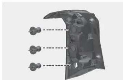
natural_image
3D diagram of a mechanical component with three dashed lines indicating alignment or assembly (no text or symbols present)- Remove the bulb from the socket by pressing it in and rotating it counterclockwise until the tabs on the bulb align with the slots in the socket. Pull the bulb out of the socket.
- Insert a new bulb by inserting it into the socket and rotating it until it locks into place.
- Install the socket into the assembly by aligning the tabs on the socket with the slots in the assembly. Push the socket into the assembly and turn the socket clockwise.
- Reinstall the lamp assembly to the body of the vehicle.
Side maker lamp (Type A,B), tail/stop lamp, turn signal lamp (Type B), garnish lamp
If the LED lamp does not operate, have the system checked by an authorized HYUNDAI dealer.
The LED lamps cannot replaced as a single unit because it is an integrated unit. The LED lamps has to be replaced with the unit.
A skilled technician should check or repair the LED lamp, for it may damage related parts of the vehicle.
Back up lamp
If the light bulb does not operate, have the vehicle checked by an authorized HYUNDI dealer.
High Mounted Stop Lamp Bulb Replacement
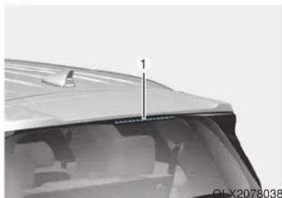
natural_image
Close-up of a car's rear window and roof structure (no visible text or symbols)If the LED lamp (1) does not operate, have the system checked by an authorized HYUNDAI dealer.
The LED lamps cannot be replaced as a single unit because it is an integrated unit. The LED lamps has to be replaced with the unit.
A skilled technician should check or repair the LED lamp, for it may damage related parts of the vehicle.
License Plate Light Bulb Replacement
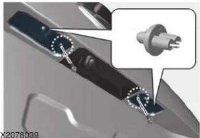
natural_image
Close-up of a mechanical component with two circular fasteners and a connector, no visible text or symbols- Loosen the lens retaining screws with a cross-tip screwdriver.
- Using a flat-blade screwdriver, gently pry the lens cover from the lamp housing.
- Remove the socket by turning it counterclockwise.
- Remove the bulb by pulling it straight out.
- Install a new bulb.
- Reinstall in the reverse order.
Interior Light Bulb Replacement
Map lamp, room lamp, vanity mirror lamp and luggage compartment lamp (Bulb type)
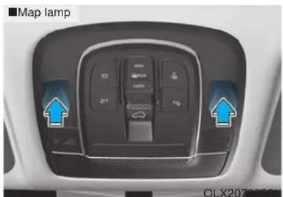
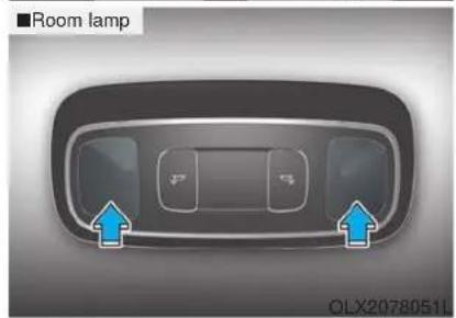
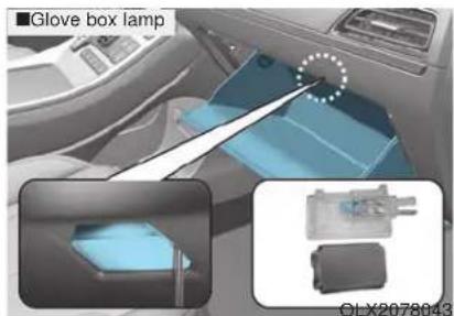
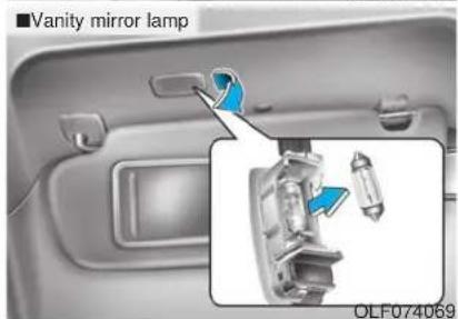
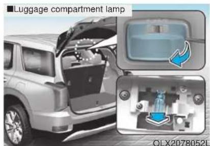
- Using a flat-blade screwdriver, gently pry the lens from the interior lamp housing.
WARNING
Prior to working on the Interior Lights, ensure that the "OFF" button is depressed to avoid burning your fingers or receiving an electric shock.
Maintenance
- Remove the bulb by pulling it straight out.
- Install a new bulb in the socket.
- Align the lens tabs with the interior lamp housing notches and snap the lens into place.
NOTICE
Use care not to dirty or damage lens, lens tab, and plastic housings.
Map lamp / Room lamp / Luggage compartment lamp (LED Type)
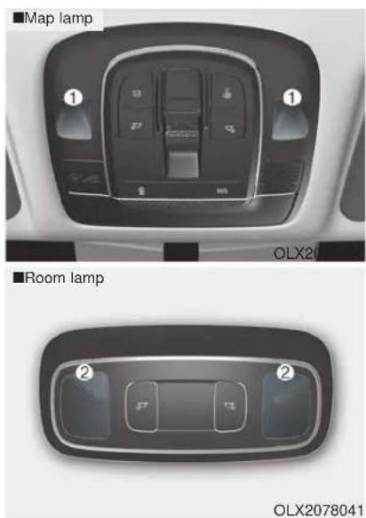
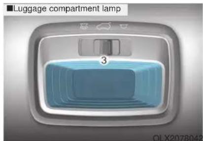
If the LED lamp (1) does not operate, have the system checked by an authorized HYUNDAI dealer.
The LED lamps cannot be replaced as a single unit because it is an integrated unit. The LED lamps has to be replaced with the unit.
A skilled technician should check or repair the LED lamp, for it may damage related parts of the vehicle
APPEARANCE CARE
Exterior Care
Exterior general caution
It is very important to follow the label directions when using any chemical cleaner or polish. Read all warning and caution statements that appear on the label.
Protecting your vehicle's finish
Washing
To help protect your vehicle's finish from rust and deterioration, wash it thoroughly and frequently at least once a month with lukewarm or cold water.
If you use your vehicle for off-road driving, you should wash it after each off-road trip. Pay special attention to the removal of any accumulation of salt, dirt, mud, and other foreign materials. Make sure the drain holes in the lower edges of the doors and rocker panels are kept clear and clean.
Insects, tar, tree sap, bird droppings, industrial pollution and similar deposits can damage your vehicle's finish if not removed immediately.
Even prompt washing with plain water may not completely remove all these deposits. A mild soap, safe for use on painted surfaces, should be used.
After washing, rinse the vehicle thoroughly with lukewarm or cold water. Do not allow soap to dry on the finish.
WARNING
After washing the vehicle, test the brakes while driving slowly to see if they have been affected by water before getting on the road. If braking performance is impaired, dry the brakes by applying them lightly while maintaining a slow forward speed.
NOTICE
- Do not use strong soap, chemical detergents or hot water, and do not wash the vehicle in direct sunlight or when the body of the vehicle is warm.
- Be careful when washing the side windows of your vehicle. Especially, with high-pressure water, water may leak through the windows and wet the interior.
• To prevent damage to the plastic parts, do not clean with chemical solvents or strong detergents.
High-pressure washing
- When using high-pressure washers, make sure to maintain sufficient distance from the vehicle. Insufficient clearance or excessive pressure can lead to component damage or water penetration.
- Do not spray the camera, sensors or its surrounding area directly with a high pressure washer. Shock applied from high pressure water may cause the device to not operate normally.
- Do not bring the nozzle tip close to boots (rubber or plastic covers)or connectors as they may be damaged if they come into contact with high pressure water.
- Do not use any high-pressure nozzles, which induce either one-direct water stream or water swirling.
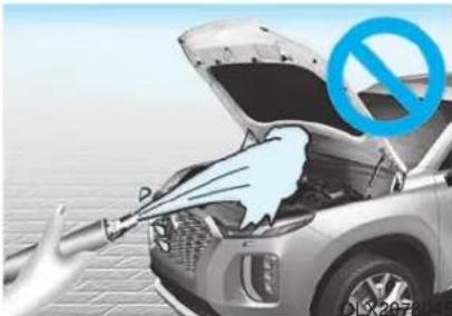
natural_image
Illustration of an open car with exhaust pipe and a blue prohibition symbol (no text or labels)NOTICE
• Water washing in the engine compartment including high pressure water washing may cause the failure of electrical circuits located in the engine compartment.
- Never allow water or other liquids to come in contact with electrical/electronic components inside the vehicle as this may damage them.
NOTICE
Matte paint finish vehicle (if equipped)
Automatic car wash which uses rotating brushes should not be used as this can damage the surface of your vehicle. A steam cleaner which washes the vehicle surface at high temperature may result the oil to adhere and leave stains that is difficult to remove.
Use a soft cloth (e.g. microfiber towel or sponge) when washing your vehicle and dry with a microfiber towel. When you hand wash your vehicle, you should not use a cleaner that finishes with wax. If the vehicle surface is too dirty (sand, dirt, dust, contaminant, etc.), clean the surface with water before washing the car.
Waxing
A good coat of wax provides a barrier between your paint and environmental contamination.
Keeping a good coat of wax on your vehicle will help protect it.
Wax the vehicle when water will no longer bead on the paint.
Always wash and dry the vehicle before waxing. Use a good quality liquid or paste wax, and follow the manufacturer's instructions. Wax all metal trim to protect it and to maintain its luster.
Removing oil, tar, and similar materials with a spot remover will usually strip the wax from the finish. Be sure to re-wax these areas even if the rest of the vehicle does not yet need waxing.
NOTICE
- Wiping dust or dirt off the body with a dry cloth will scratch the finish.
- Do not use steel wool, abrasive cleaners, or strong detergents containing highly alkaline or caustic agents on chrome-plated or anodized aluminum parts. This may result in damage to the protective coating and cause discoloration or paint deterioration.
NOTICE
Matte paint finish vehicle (if equipped)
Do not use any polish protector such as a detergent, an abrasive and a polish. In case wax is applied, remove the wax immediately using a silicon remover and if any tar or tar contaminant is on the surface use a tar remover to clean. However, be careful not to apply too much pressure on the painted area.
Repairing your vehicle's finish
Deep scratches or stone chips in the painted surface must be repaired promptly. Exposed metal will quickly rust and may develop into a major repair expense.
NOTICE
If your vehicle is damaged and requires any metal repair or replacement, be sure the body shop applies anti-corrosion materials to the parts repaired or replaced.
NOTICE
Matte paint finish vehicle (if equipped)
In case of matte paint finish vehicles, it is impossible to modify only the damaged area and repair of the whole part is necessary. If the vehicle is damaged and painting is required, we recommend that you have your vehicle maintained and repaired by an authorized HYUNDAI dealer. Take extreme care, as it is difficult to restore the quality after the repair.
7-71
Bright-metal maintenance
- To remove road tar and insects, use a tar remover, not a scraper or other sharp object.
- To protect the surfaces of bright-metal parts from corrosion, apply a coating of wax or chrome preservative and rub to a high luster.
- During winter weather or in coastal areas, cover the bright metal parts with a heavier coating of wax or preservative. If necessary, coat the parts with non-corrosive petroleum jelly or other protective compound.
Underbody maintenance
Corrosive materials used for ice and snow removal and dust control may collect on the underbody. If these materials are not removed, accelerated rusting can occur on underbody parts such as the fuel lines, frame, floor pan and exhaust system, even though they have been treated with rust protection.
Thoroughly flush the vehicle underbody and wheel openings with lukewarm or cold water once a month, after off-road driving and at the end of each winter. Pay special attention to these areas because it is difficult to see all the mud and dirt. It will do more harm than good to wet down the road grime without removing it. The lower edges of doors, rocker panels, and frame members have drain holes that should not be allowed to clog with dirt; trapped water in these areas can cause rusting.
WARNING
After washing the vehicle, test the brakes while driving slowly to see if they have been affected by water. If braking performance is impaired, dry the brakes by applying them lightly while maintaining a slow forward speed.
Aluminum wheel maintenance
The aluminum wheels are coated with a clear protective finish.
NOTICE
- Do not use abrasive cleaner, polishing compound, solvent, or wire brushes on aluminum wheels.
- Clean the wheel when it has cooled.
- Use only a mild soap or neutral detergent, and rinse thoroughly with water. Also, clean the wheels after driving on salted roads.
- Do not wash the wheels with high-speed car wash brushes.
- Do not use any cleaners containing acid or alkaline detergents.
Corrosion protection
Protecting your vehicle from corrosion
By using the most advanced design and construction practices to combat corrosion, HYUNDAI produces vehicles of the highest quality. However, this is only part of the job. To achieve the long-term corrosion resistance your vehicle can deliver, the owner's cooperation and assistance is also required.
Common causes of corrosion
The most common causes of corrosion on your vehicle are:
- Road salt, dirt and moisture that is allowed to accumulate underneath the vehicle.
- Removal of paint or protective coatings by stones, gravel, abrasion or minor scrapes and dents which leave unprotected metal exposed to corrosion.
High-corrosion areas
If you live in an area where your vehicle is regularly exposed to corrosive materials, corrosion protection is particularly important. Some of the common causes of accelerated corrosion are road salts, dust control chemicals, ocean air and industrial pollution.
Moisture breeds corrosion
Moisture creates the conditions in which corrosion is most likely to occur. For example, corrosion is accelerated by high humidity, particularly when temperatures are just above freezing. In such conditions, the corrosive material is kept in contact with the car surfaces by moisture that is slow to evaporate.
Mud is particularly corrosive because it is slow to dry and holds moisture in contact with the vehicle. Although the mud appears to be dry, it can still retain the moisture and promote corrosion.
High temperatures can also accelerate corrosion of parts that are not properly ventilated so the moisture can be dispersed. For all these reasons, it is particularly important to keep your vehicle clean and free of mud or accumulations of other materials. This applies not only to the visible surfaces but particularly to the underside of the vehicle.
To help prevent corrosion
Keep your vehicle clean
The best way to prevent corrosion is to keep your vehicle clean and free of corrosive materials. Attention to the underside of the vehicle is particularly important.
- If you live in a high-corrosion area — where road salts are used, near the ocean, areas with industrial pollution, acid rain, etc.—, you should take extra care to prevent corrosion. In winter, hose off the underside of your vehicle at least once a month and be sure to clean the underside thoroughly when winter is over.
- When cleaning underneath the vehicle, pay particular attention to the components under the fenders and other areas that are hidden from view. Do a thorough job; just dampening the accumulated mud rather than washing it away will accelerate corrosion rather than prevent it. Water under high pressure and steam are particularly effective in removing accumulated mud and corrosive materials.
- When cleaning lower door panels, rocker panels and frame members, be sure that drain holes are kept open so that moisture can escape and not be trapped inside to accelerate corrosion.
Keep your garage dry
Don't park your vehicle in a damp, poorly ventilated garage. This creates a favorable environment for corrosion. This is particularly true if you wash your vehicle in the garage or drive it into the garage when it is still wet or covered with snow, ice or mud. Even a heated garage can contribute to corrosion unless it is well ventilated so moisture is dispersed.
Keep paint and trim in good condition Scratches or chips in the finish should be covered with "touch-up" paint as soon as possible to reduce the possibility of corrosion. If bare metal is showing through, the attention of a qualified body and paint shop is recommended.
Bird droppings are highly corrosive and may damage painted surfaces in just a few hours. Always remove bird droppings as soon as possible.
Interior Care
Interior general precautions
Prevent caustic solutions such as perfume and cosmetic oil, from contacting the interior parts because they may cause damage or discoloration. If they do contact the interior parts, wipe them off immediately. See the instructions for the proper way to clean vinyl.
NOTICE
- Never allow water or other liquids to come in contact with electrical/electronic components inside the vehicle as this may damage them.
- When cleaning leather products (steering wheel, seats etc.), use neutral detergents or low alcohol content solutions. If you use high alcohol content solutions or acid/alkaline detergents, the color of the leather may fade or the surface may get stripped off.
Cleaning the upholstery and interior trim
Vinyl (if equipped)
Remove dust and loose dirt from vinyl with a whisk broom or vacuum cleaner. Clean vinyl surfaces with a vinyl cleaner.
Fabric (if equipped)
Remove dust and loose dirt from fabric with a whisk broom or vacuum cleaner. Clean with a mild soap solution recommended for upholstery or carpets. Remove fresh spots immediately with a fabric spot cleaner. If fresh spots do not receive immediate attention, the fabric can be stained and its color can be affected. Also, its fire-resistant properties can be reduced if the material is not properly maintained.
NOTICE
Using anything but recommended cleaners and procedures may affect the fabric's appearance and fire-resistant properties.
Leather (if equipped)
- Features of seat leather
- Leather is made from the outer skin of an animal, which goes through a special process to be available for use. Since it is a natural product, each part differs in thickness or density.
Wrinkles may appear as a natural result of stretching and shrinking depending on the temperature and humidity.
- The seat is made of stretchable fabric to improve comfort.
- The parts contacting the body are curved and the side supporting area is high which provides driving comfort and stability.
- Wrinkles may appear naturally from usage. It is not a fault of the products.
CAUTION
- Wrinkles or abrasions which appear naturally from usage are not covered by warranty.
- Belts with metallic accessories, zippers or keys inside the back pocket may damage the seat fabric.
- Make sure not to wet the seat. It may change the nature of natural leather.
- Jeans or clothes which could bleach may contaminate the surface of the seat covering fabric.
• Caring for the leather seats
- Vacuum the seat periodically to remove dust and sand on the seat. It will prevent abrasion or damage of the leather and maintain its quality.
- Wipe the natural leather seat cover often with dry or soft cloth.
- Use of proper leather protector may prevent abrasion of the cover and helps maintain the color. Be sure to read the instructions and consult a specialist when using leather coating or protective agent.
- Light colored (beige, cream beige) leather is easily contaminated and the stain is noticeable. Clean the seats frequently.
- Avoid wiping with wet cloth. It may cause the surface to crack.
- Cleaning the leather seats
- Remove all contaminations instantly. Refer to instructions below for removal of each contaminant.
- Cosmetic products (sunscreen, foundation, etc.)
Apply cleansing cream on a cloth and wipe the contaminated spot. Wipe off the cream with a wet cloth and remove water with a dry cloth.
- Beverages (coffee, soft drink, etc.)
Apply a small amount of neutral detergent and wipe until contaminations do not smear.
- Oil
Remove oil instantly with absorbable cloth and wipe with stain remover used only for natural leather.
- Chewing gum
Harden the gum with ice and remove gradually.
Cleaning the seat belt webbing
Clean the belt webbing with any mild soap solution recommended for cleaning upholstery or carpet. Follow the instructions provided with the soap. Do not bleach or re-dye the webbing because this may weaken the seat belt.
Cleaning the interior window glass
If the interior glass surfaces of the vehicle become fogged (that is, covered with an oily, greasy or waxy film), they should be cleaned with glass cleaner. Follow the directions on the glass cleaner container.
NOTICE
Do not scrape or scratch the inside of the rear window. This may result in damage to the rear window defroster grid.
The emission control system of your vehicle is covered by a written limited warranty. Please see the warranty information contained in the Owner's Handbook & Warranty Information booklet in your vehicle.
Your vehicle is equipped with an emission control system to meet all applicable emission regulations. There are three emission control systems, as follows.
(1) Crankcase emission control system
(2) Evaporative emission control system
(3) Exhaust emission control system
In order to ensure the proper function of the emission control systems, it is recommended that you have your vehicle inspected and maintained by an authorized HYUNDAI dealer in accordance with the maintenance schedule in this manual.
NOTICE
For the Inspection and Maintenance Test (with Electronic Stability Control (ESC) system)
• To prevent the vehicle from mis-firing during dynamometer testing, turn the Electronic Stability Control (ESC) system off by pressing the ESC switch (ESC OFF light illuminated).
- After dynamometer testing is completed, turn the ESC system back on by pressing the ESC switch again.
- Crankcase Emission Control System
The positive crankcase ventilation system is employed to prevent air pollution caused by blow-by gases being emitted from the crankcase. This system supplies fresh filtered air to the crankcase through the air intake hose. Inside the crankcase, the fresh air mixes with blow-by gases, which then pass through the PCV valve into the induction system.
2. Evaporative Emission Control System Including Onboard Refueling Vapor Recovery (ORVR)
The Evaporative Emission Control System is designed to prevent fuel vapors from escaping into the atmosphere. The ORVR system is designed to allow the vapors from the fuel tank to be loaded into a canister while refueling at the gas station, preventing the escape of fuel vapors into the atmosphere.
Canister
Fuel vapors generated inside the fuel tank are absorbed and stored in the onboard canister. When the engine is running, the fuel vapors absorbed in the canister are drawn into the surge tank through the purge control sole-noid valve.
Purge Control Solenoid Valve (PCSV)
The purge control solenoid valve is controlled by the Engine Control Module (ECM); when the engine coolant temperature is low during idling, the PCSV closes so that evaporated fuel is not taken into the engine. After the engine warms-up during ordinary driving, the PCSV opens to introduce evaporated fuel to the engine.
3. Exhaust Emission Control System
The Exhaust Emission Control System is a highly effective system which controls exhaust emissions while maintaining good vehicle performance.
When the engine starts or fails to start, excessive attempts to restart the engine may cause damage to the emission system.
Engine exhaust (carbon monoxide) precautions
- Carbon monoxide can be present with other exhaust fumes. If you smell exhaust fumes of any kind in your vehicle, drive with all the windows fully open. Have your vehicle checked and repaired immediately.
WARNING
Engine exhaust gases contain carbon monoxide (CO). Though colorless and odorless, it is dangerous and could be lethal if inhaled. Follow the instructions on this page to avoid CO poisoning.
WARNING
CALIFORNIA PROPOSITION 65 WARNING
Engine exhaust and a wide variety of automobile components and parts, including components found in the interior furnishings in a vehicle, contain or emit chemicals known to the State of California to cause cancer and birth defects and reproductive harm. In addition, certain fluids contained in vehicles and certain products of component wear contain or emit chemicals known to the State of California to cause cancer and birth defects or other reproductive harm.
For more information go to https://www.p65warnings.ca.gov/passenger-vehicle
- Do not operate the engine in confined or closed areas (such as garages) any more than what is necessary to move the vehicle in or out of the area.
- When the vehicle is stopped in an open area for more than a short time with the engine running, adjust the ventilation system (as needed) to draw outside air into the vehicle.
- Never sit in a parked or stopped vehicle for any extended time with the engine running.
- When the engine stalls or fails to start, excessive attempts to restart the engine may cause damage to the emission control system.
Operating precautions for catalytic converters (if equipped)
WARNING
The exhaust system and catalytic converter are very hot during and immediately after the engine has been running. To avoid SERIOUS INJURY or DEATH:
- Do not park, idle, or drive the vehicle over or near flammable objects, such as grass, vegetation, paper, leaves, etc. A hot exhaust system can ignite flammable items under your vehicle.
- Keep away from the exhaust system and catalytic converter or you may get burned.
Also, Do not remove the heat sink around the exhaust system, do not seal the bottom of the vehicle, and do not coat the vehicle for corrosion control. It may present a fire risk under certain conditions.
Maintenance
Your vehicle is equipped with a catalytic converter emission control device. To prevent damage to the catalytic converter and to your vehicle, take the following precautions:
- Use only UNLEADED FUEL for gasoline engines.
- Do not operate the vehicle when there are signs of engine malfunction, such as misfire or a noticeable loss of performance.
- Do not misuse or abuse the engine. Examples of misuse are coasting with the engine off and descending steep grades in gear with the engine off.
-
Do not operate the engine at high idle speed for extended periods (5 minutes or more).
-
Do not modify or tamper with any part of the engine or emission control system. All inspections and adjustments must be made by an authorized HYUNDAI dealer.
- Avoid driving with extremely low fuel level. If you run out of gasoline, it could cause the engine to misfire and result in excessive loading of the catalytic converter.
CALIFORNIA PERCHLORATE NOTICE
Perchlorate Material-special handling may apply, See: www.dtsc.ca.gov/hazardouswaste/perchlorate.
Notice to California Vehicle Dismantlers:
Perchlorate containing materials, such as air bag inflators, seatbelt pretensioners and keyless remote entry batteries, must be disposed of according to Title 22 California Code of Regulations Section 67384.10 (a).
Specifications, Consumer information and Reporting safety defects
Dimensions....8-2
Engine....8-2
Bulb Wattage 8-3
Tires and Wheels 8-5
Volume and Weight....8-6
Air Conditioning System....8-6
Recommended Lubricants and Capacities......8-7
Recommended SAE Viscosity Number......8-9
Vehicle Identification Number (VIN) 8-10
Vehicle Ccertification Label....8-10
Tire Specification and Pressure Label .....8-11
Engine Number....8-11
Refrigerant Label....8-11
Consumer Information....8-12
Reporting Safety Defects 8-13
DIMENSIONS
| Items in (mm) | ||
| Overall length 196.06 (4,980) | ||
| Overall width 77.75 (1,975) | ||
| Overall height 68.89 (1,750) | ||
| Front tread | 245/60 R18 67.24 | (1,708) |
| 245/50 R20 67.24 | (1,708) | |
| Rear tread | 245/60 R18 67.56 | (1,716) |
| 245/50 R20 67.56 | (1,716) | |
| Wheelbase 114.17 (2,900) | ||
ENGINE
| Item Gasoline 3.8 GDI | |
| Displacementcu. in (cc) | 230.55(3,778) |
| Bore x Strokein. (mm) | 3.78 × 3.43 (96 x 87) |
| Firing order | 1-2-3-4-5-6 |
| No. of cylinders | 6, V-type |
BULB WATTAGE
| Light Bulb Bulb Type Wattage | |||||
| Front | Headlamp | Low | Type A HB3 60 | ||
| Type B LED LED | |||||
| High | Type A H7 | 55 | |||
| Type B LED LED | |||||
| Daytime running lamp(DRL) & Parking lamp | Type A LED LED | ||||
| Type B LED LED | |||||
| Turn signal lamp | LED LED | ||||
| Turn signal lamp (Outside mirror) | LED LED | ||||
| Side marker lamp | LED LED | ||||
| Rear | Tail lamp | Type A | P28/8W | 28/8 | |
| Type B LED LED | |||||
| Tail/Stop lamp | Type A | P28/8W | 28/8 | ||
| Type B LED LED | |||||
| Turn signal lamp | Type A | P28/8W | 28/8 | ||
| Type B LED LED | |||||
| Side marker lamp | Type A LED LED | ||||
| Type B LED LED | |||||
| Back up lamp | P21W 21 | ||||
| Rear fog lamp | LED LED | ||||
| High mounted stop lamp | LED LED | ||||
| License plate lamp | W5W 5 | ||||
| Interior | Map lamp | Type A W8W 8 | |||
| Type B LED LED | |||||
| Room lamp | Type A W8W 28/8 | ||||
| Type B LED LED | |||||
| Luggage compartment lamp | Type A FESTOON 8 | ||||
| Type B LED LED | |||||
| Vanity mirror lamp | Type A 5W 5 | ||||
| Type B LED LED | |||||
| Grove box lamp FESTOON 5 | |||||
TIRES AND WHEELS
| Item | Tire Size | Wheel Size | Cold tire inflation pressure, kPa (psi) | Wheel Lug Nut Torque kgf·m (lbf·ft, N·m) | |
| Front | Rear | ||||
| Full size tire | 245/60 R18 | 7.5J X 18 | 240 (35) | 240 (35) | 11~13(79~94,107~127) |
| 245/50 R20 | 7.5J X 20 | ||||
| Compact spare tire | T155/90 R18 | 4.0T X 18 | 420 (60) | ||
NOTICE
- It is permissible to add 3 psi to the standard tire pressure specification if colder temperatures are expected soon.
Tires typically loose 1psi (7kPa) for every 12°F temperature drop. If extreme temperature variations are expected, recheck your tire pressure as necessary to keep them properly inflated.
- An air pressure generally decreases, as you drive up to a high-altitude area above sea level. Thus, if you plan to drive a high-altitude area, check the tire pressures in advance. If necessary, inflate them to a proper level. (Air inflation per altitude: +2.4 psi/1 mile)
CAUTION
When replacing tires, use the same size originally supplied with the vehicle. Using tires of a different size can damage the related parts or not work properly.
VOLUME AND WEIGHT
| Items | 3.8 GDI | ||
| 2WD AWD | |||
| Gross vehicle weight | 7 Seaterlbs. (kg) | 5,732 (2,600) 5,871 | (2,663) |
| 8 Seaterlbs. (kg) | 5,732 (2,600) 5,871 | (2,663) | |
| Luggage volume (SAE)cu. ft (/) | Behind 1^st row : 86.4 (2447)Behind 2^st row : 45.8 (1297)Behind 3^st row : 18 (509) | ||
AIR CONDITIONING SYSTEM
| Items | Weight of Volume | Classification |
| Refrigerantoz. (g) | 31.75 (900) ± 0.88 (25) | R134a |
| Compressor lubricantoz. (cc) | 6.35 (180) | PAG |
Contact an authorized HYUNDAI dealer for more details.
RECOMMENDED LUBRICANTS AND CAPACITIES
To help achieve proper engine and powertrain performance and durability, use only lubricants of the proper quality. The correct lubricants also help promote engine efficiency that results in improved fuel economy.
| Lubricant Volume Classification | ||
Engine oil *1 *2 (drain and refill)Recommends | 6.87 US qt. (6.5 l) | ACEA A5 or above *3 /5W-30 /(SAE Viscosity Number) |
| Automatic transmission fluid | 7.4 US qt. (7.0 l) | MICHANG ATF SP-IV,SK ATF SP-IV,NOCA ATF SP-IV,HYUNDAI genuine ATF SP-IV or other brands meeting the above specification approved by HYUNDAI Motor Co. |
*1 : Refer to the recommended SAE viscosity numbers on the 9 page.
*2 : Engine oils labeled Energy Conserving Oil are now available. Along with other additional benefits, they contribute to fuel economy by reducing the amount of fuel necessary to overcome engine friction. Often, these improvements are difficult to measure in everyday driving, but in a year's time, they can offer significant cost and energy savings.
^*3 : If the ACEA A5 engine oil is not available in your country, you are able to use API SM & ILSAC GF-4 (or above) or ACEA A3.
| Lubricant Volume Classification | ||
| Transfer case oil (AWD) | 0.74 US qt. (0.7 l) | HYPOID GEAR OIL API GL-5, SAE 75W/85(SK HCT-5 GEAR OIL 75W/85 or EQUIVALENT) |
| Rear differential oil (AWD) | 0.74 US qt. (0.7 l) | |
| Coolant | 9.4 US qt. (8.9 l) | Mixture of antifreeze and water(Phosphate-based Ethylene glycol coolant for alu-minum radiator) |
| Brake fluid | As required FMVS | S116 DOT-4 |
| Fuel | 18.75 US gal. (71 l) | Refer to "Fuel requirements" in the Foreword chapter. |
Recommended SAE viscosity number
CAUTION
Always be sure to clean the area around any filler plug, drain plug, or dipstick before checking or draining any lubricant. This is especially important in dusty or sandy areas and when the vehicle is used on unpaved roads. Cleaning the plug and dipstick areas will prevent dirt and grit from entering the engine and other mechanisms that could be damaged.
Engine oil viscosity (thickness) has an effect on fuel economy and cold weather operating (engine start and engine oil flowability). Lower viscosity engine oils can provide better fuel economy and cold weather performance, however, higher viscosity engine oils are required for satisfactory lubrication in hot weather.
Using oils of any viscosity other than those recommended could result in engine damage.
When choosing an oil, consider the range of temperature your vehicle will be operated in before the next oil change. Proceed to select the recommended oil viscosity from the chart.
| Temperature Range for SAE Viscosity Numbers | ||||||||||
| Temperature | °C | -30 | -20 | -10 | 0 | 10 | 20 | 30 | 40 | 50 |
| (°F) | -10 | 0 | 20 | 40 | 60 | 80 | 100 | 120 | ||
| Engine Oil *1 | 10W-30 | |||||||||
| 5W-30 | ||||||||||
*1: For better fuel economy, it is recommended to use the engine oil of a viscosity grade SAE 5W-30. However, if the engine oil is not available in your country, select the proper engine oil using the engine oil viscosity chart.

VEHICLE IDENTIFICATION NUMBER (VIN)
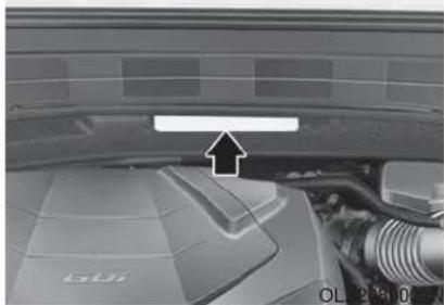
natural_image
Close-up of a car engine bay with a white arrow pointing to a component, no visible text or symbolsThe vehicle identification number (VIN) is the number used in registering your car and in all legal matters pertaining to its ownership, etc.
The number is punched on the engine compartment frame and back side of the engine.
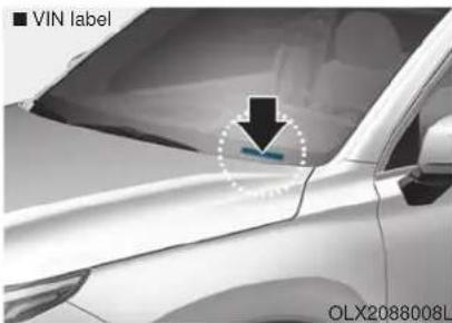
The VIN is also on a plate attached to the top of the dashboard. The number on the plate can easily be seen through the windshield from outside.
VEHICLE CERTIFICATION LABEL
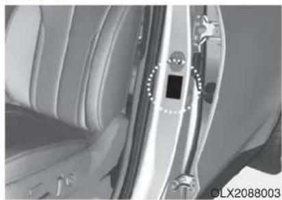
natural_image
Close-up of a car interior showing the door, seatbelt, and dashboard (no visible text or symbols)The vehicle certification label attached on the driver's side center pillar gives the Vehicle Identification Number (VIN).
TIRE SPECIFICATION AND PRESSURE LABEL
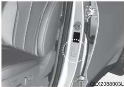
natural_image
Close-up of a car interior showing the door, seatbelt, and camera (no visible text or symbols)The tires supplied on your new vehicle are chosen to provide the best performance for normal driving.
The tire label located on the driver's side center pillar gives the tire pressures recommended for your car.
ENGINE NUMBER
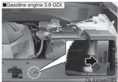
The engine number is stamped on the engine block as shown in the drawing.
REFRIGERANT LABEL (IF EQUIPPED)
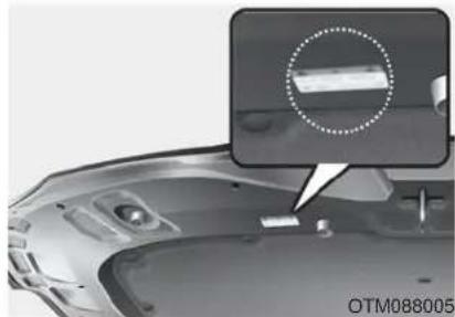
natural_image
Close-up of a car's front bumper with a magnified inset showing a component detail (no text or symbols visible)The refrigerant label provides information such as refrigerant type and amount.
CONSUMER INFORMATION
This consumer information has been prepared in accordance with regulations issued by the National Highway Traffic Safety Administration of the U.S. Department of Transportation. Your HYUNDAI dealer will help answer any questions you may have as you read this information.
HYUNDAI motor vehicles are designed and manufactured to meet or exceed all applicable safety standards.
For your safety, however, we strongly urge you to read and follow all directions in this Owner's Manual, particularly the information under the headings "NOTICE", "CAUTION" and "WARNING".
If, after reading this manual, you have any questions regarding the operation of your vehicle, please contact your nearest HYUNDAI Motor America Regional Office as listed in the following:
Eastern Region:
Connecticut, Delaware, Maine, Massachusetts, New Hampshire, New Jersey, New York, Pennsylvania, Rhode Island, Vermont. Eastern Region 1122 Cranbury South River Road Jamesburg, NJ 08831 (800) 633-5151
Southern Region:
Florida, Georgia, Maryland, North Carolina, South Carolina, Virginia, West Virginia. Southern Region 3025 Chastain Meadows Parkway Suite 100 Marietta, GA 30066 (800) 633-5151
South Central Region:
Alabama, Arkansas, Louisiana, Mississippi, New Mexico, Oklahoma, Tennessee, Texas. South Central Region 1421 South Beltline Road, Suite 400 Coppell, TX 75019 (800) 633-5151
Central Region:
Illinois, Indiana, Iowa, Kentucky, Michigan, Minnesota, Nebraska, North Dakota, South Dakota, Ohio, Wisconsin, Kansas, Missouri. Central Region 2 Trans Am Plaza Dr #500 Oakbrook Terrace, IL 60181 (800) 633-5151
Western Region:
Alaska, Hawaii, Arizona, California, Colorado, Idaho, Montana, Nevada, Oregon, Utah, Washington, Wyoming. Western Region 10550 Talbert Avenue P.O.Box 20850 Fountain Valley, California 92728-0850 (800) 633-5151
REPORTING SAFETY DEFECTS
If you believe that your vehicle has a defect which could cause a crash or could cause injury or death, you should immediately inform the National Highway Traffic Safety Administration (NHTSA) in addition to notifying HYUNDAI MOTOR AMERICA.
To contact NHTSA, you may call the Vehicle Safety Hotline toll-free at 1-888-327-4236 (TTY: 1-800-424-9153); go to http://www.safercar.gov;
download the SaferCar mobile application;
or write to: Administrator, NHTSA
1200 New Jersey Ave, SE,
West Building Washington, D.C. 20590.
You can also obtain other information about motor vehicle safety from http://www.safercar.gov.
If NHTSA receives similar complaints, it may open an investigation, and if it finds that a safety defect exists in a group of vehicles, it may order a recall and remedy campaign. However, NHTSA cannot become involved in individual problems between you, your dealer, or HYUNDAI MOTOR AMERICA.
Index
Index
A
AC inverter 3-198
Air bag warning labels....2-79
Air bags....2-57
Additional safety precautions....2-79
Air bag collision sensors 2-73
Air bag inflation conditions 2-75
Air bag non-inflation conditions 2-76
Air bag warning labels 2-79
Curtain air bags 2-62
Do not install a child restraint on the front passenger seat....2-72
Driver's air bag 2-59
Driver's knee air bag 2-59
How does the air bags system operate? 2-63
Occupant classification system (OCS)....2-68
Passenger's front air bag....2-59
Side air bags 2-60
SRS Care 2-78
SRS components and functions....2-63
SRS warning light 2-63
What to expect after an air bag inflates 2-67
Why didn't my air bag go off in a collision .....2-73
Air cleaner filter replacement 7-22
Air conditioning refrigerant label 3-185
Air conditioning system specification ....8-6
All Wheel Drive (AWD)....5-43
Antenna 4-2
Anti-lock Brake System (ABS) 5-33
Appearance care....7-69
Exterior care 7-69
Interior care 7-74
Armrest 2-20
Audio/Video/Navigation system....4-4
Auto defogging system 3-188
Auto headlamp position....3-132
Automatic climate control system ....3-171
Air conditioning 3-178
Air intake control 3-176
Automatic heating and air conditioning....3-172
Fan speed control 3-177
Manual heating and air conditioning ....3-173
Mode selection 3-174
OFF mode....3-178
Rear climate control button....3-178
System maintenance....3-184
Temperature control 3-175
Automatic transmission 5-15
Good driving practices 5-20
Paddle shifter....5-22
Parking....5-18
Shift lock system 5-17
Automatic ventilation 3-191
B
Battery....7-29
Battery recharging 7-31
Battery saver function....3-138
Before driving 5-5
Blind-Spot Collision Warning (BCW) system ....5-78
Blind-Spot Collision-Avoidance Assist (BCA) system ..5-78
Blind-spot view monitor system....3-150
Bluetooth® Wireless Technology 4-4
Brake fluid 7-21
Brake system....5-23
Anti-lock Brake System (ABS)....5-33
Auto hold....5-29
Disc brakes wear indicator....5-24
Downhill Brake Control (DBC)......5-39
Electronic Parking Brake (EPB) 5-24
Electronic Stability Control (ESC)......5-35
Good braking practices 5-42
Hill-start Assist Control (HAC) 5-39
Power brakes 5-23
Trailer Stability Assist (TSA)....5-42
Vehicle Stability Management (VSM) 5-38
Bulb replacement 7-61
Daytime running light (DRL) 7-61, 7-63
Front parking lamp 7-61, 7-63
Front turn signal lamp....7-61, 7-63
Headlamp 7-61, 7-63
High mounted stop lamp 7-66
Interior light....7-67
License plate light 7-66
Rear combination light bulb....7-64
Side marker lamp....7-61, 7-63
Side repeater lamp....7-64
Bulb wattage 8-3
C
Capacities (Lubricants) 8-7
Care
Exterior care 7-69
Interior care 7-74
Tire care....7-33
Cargo security screen....3-205
Center console storage....3-192
Central door lock/unlock switch....3-17
Certification label 8-10
Check tire inflation pressure....7-35
Index
Child restraint system (CRS)....2-46
Booster seats....2-48
Forward-facing child restraints 2-48
Installing a child restraint system (CRS) ......2-49
Lower anchors and tether for children (LATCH system) 2-50
Securing a child restraint seat with "Tether Anchor" system....2-52
Securing a child restraint with lap/shoulder belt .....2-53
Securing a child restraint with the LATCH anchors system....2-51
Selecting a child restraint system (CRS) 2-47
Child-protector rear door lock 3-20
Climate control air filter 7-24
Clock 3-203
Cluster ionizer....3-191
Coat hanger 3-203
Crankcase emission control system....7-77
Cup holder....3-194
Curtain air bags....2-62
D
Day/night rearview mirror 3-33
Daytime running light (DRL) 3-132
Defroster 3-190
Rear window defroster 3-190
Dimensions 8-2
Door locks....3-15
Auto door lock/unlock features....3-19
Central door lock/unlock switch 3-17
Child-protector rear door lock....3-20
Electronic child safety lock system....3-20
Downhill Brake Control (DBC) 5-39
Drive Mode....5-55, 5-59
Drive mode integrated control system Drive Mode ....5-55
Drive mode integrated control system (AWD) Drive Mode ....5-59
Driver Attention Warning (DAW) system ....5-117
Driver position memory system 3-27
Easy access function 3-29
Recalling positions from memory....3-28
Resetting the driver's seat memory system ....3-28
Storing positions into memory....3-27
Driver's air bag....2-59
Driver's knee air bag 2-59
Driving at night....5-149
Driving in flooded areas 5-150
Driving in the rain....5-149
E
Electric power steering (EPS)....3-30
Electrochromatic mirror (ECM) 3-34
Electronic child safety lock system 3-20
Electronic Parking Brake (EPB)....5-24
Electronic Stability Control (ESC) 5-35
Emergency towing 6-24
Emission control system 7-77
Crankcase emission control system 7-77
Evaporative emission control System 7-77
Exhaust emission control system 7-78
Engine compartment....1-6, 7-3
Engine compartment panel fuse replacement....7-50
Engine coolant 7-18
Engine coolant temperature gauge 3-72
Engine number 8-11
Engine oil....7-16
Engine specification....8-2
Engine Start/Stop button....5-10
Evaporative emission control System....7-77
Exhaust emission control system....7-78
Explanation of scheduled maintenance items....7-13
Exterior care....7-69
Exterior features....3-209
Roof side rails 3-209
Exterior overview 1-2
Front view 1-2
Rear view....1-3
F
Flat tire....6-14
Changing a tire 6-16
Floor mat anchor(s)....3-204
Fluid Brake fluid....7-21
Washer fluid 7-22
Forward Collision-Avoidance Assist (FCA) system .....5-63
Front air ventilation seat 2-27
Front seat head restraints 2-22
Front seats 2-6
Manual adjustment 2-7
Power adjustment 2-9
Reclining seatback 2-8, 2-10
Seatback pocket....2-12
Front windshield washers 3-146
Front windshield wipers 3-144
Fuel requirements Fuel additives ....F8
Unleaded....F7
Index
Fuses 7-48
Engine compartment panel fuse replacement .....7-50
Fuse/relay panel description....7-51
Instrument panel fuse replacement....7-49
Multi fuse 7-50
G
Gauges and meters....3-71
Glove box....3-192
Grove box lamp 3-141
H
Hazard warning flasher....6-2
Hazardous driving conditions 5-148
Head Restraints 2-21
Front seat head restraints....2-22
Rear seat head restraints....2-24
Head up display 3-130
Headlamp delay function....3-138
Headlamp position 3-133
Heated steering wheel....3-32
High Beam Assist (HBA) 3-134
High beam operation....3-134
Highway driving 5-150
Highway Driving Assist (HDA) system 5-121
Hill-start Assist Control (HAC)....5-39
Hood....3-53
Horn 3-31
How to use this manual ......F6
|
Idle Stop and Go (ISG) System....5-50
If the engine doesn't turn over or turns over slowly......6-3
If the engine overheats....6-6
If the engine stalls at a crossroad or crossing....6-2
If the engine stalls while driving 6-2
If the engine turns over normally but doesn't start....6-3
If the engine will not start....6-3
If you have a flat tire while driving....6-3
Immobilizer system....3-14
Important safety precautions....2-2
Air Bag Hazards....2-2
Always Wear Your Seat Belt 2-2
Control Your Speed 2-3
Driver Distraction....2-2
Keep Your Vehicle in Safe Condition 2-3
Restrain All Children....2-2
In case of emergency while driving....6-2
Infotainment system....4-2
Antenna 4-2
Audio/Video/Navigation system 4-4
Bluetooth® Wireless Technology....4-4
Steering wheel audio controls 4-3
USB port....4-2
Inside rearview mirror 3-33
Instrument cluster 3-69
Assist mode 3-98
Adjusting instrument cluster illumination....3-69
Gauges and meters 3-71
LCD display control....3-96
LCD display messages 3-90
LCD display modes....3-97
Option menu 3-119
Transmission shift indicator 3-76
Trip computer mode 3-110
User settings mode 3-100
Warning and indicator lights 3-76
Instrument panel fuse replacement 7-49
Instrument panel overview 1-5
Interior care....7-74
Interior features
AC inverter....3-198
Cargo security screen 3-205
Clock 3-203
Coat hanger 3-203
Conversation mirror 3-196
Cup holder 3-194
Floor mat anchor(s) 3-204
Luggage net (holder) 3-205
Power outlet....3-197
Side curtain....3-207
Sunvisor....3-196
USB charger 3-200
Wireless cellular phone charging system ....3-201
Interior lamp AUTO cut....3-139
Interior lights....3-139
Front lamps....3-139
Grove box lamp....3-141
Interior lamp AUTO cut 3-139
Luggage compartment lamp....3-140
Puddle lamp....3-141
Rear lamps....3-140
Vanity mirror lamp 3-141
Interior overview....1-4
J
Jump starting....6-4
K
Key ignition switch....5-7
L
Label
Tire sidewall labeling 7-39
Tire specification and pressure label....8-11
Vehicle certification label....8-10
Lane change signals....3-137
Lane Following Assist (LFA) system 5-103
Lane Keeping Assist (LKA) system 5-109
LCD display
Assist mode 3-98
Driving assist view mode 3-117
LCD display modes....3-97
Master warning mode....3-99
Other information display 3-118
Parking assist view mode 3-117
Trip computer mode 3-98
Turn By Turn (TBT) mode....3-117
User settings mode 3-100
Utility view mode....3-116
View modes 3-115
LCD display messages
Battery discharging due to external electrical devices....3-91
Check Blind-Spot Collision Warning system ....3-94
Check BRAKE SWITCH fuse....3-91
Check Driver Attention Warning (DAW) system .....3-95
Check Forward Collision-Avoidance Assist system ..3-94
Check headlight....3-94
Check headlight LED....3-94
Check High Beam Assist (HBA) system 3-94
Check Lane Keeping Assist (LKA) system 3-95
Check Smart Cruise Control system 3-95
Door, Hood, Trunk open indicator 3-91
Engine has overheated....3-93
Heated steering wheel turned off 3-93
Key not detected....3-90
Key not in vehicle 3-90
Lights mode....3-93
Low fuel 3-93
Low key battery....3-90
Low pressure 3-92
Low washer fluid....3-93
Press brake pedal to start engine....3-90
Press START button again 3-90
Press START button with key 3-91
Shift to P or N to start engine 3-90
Sunroof open indicator....3-92
Window open indicator 3-92
Wiper mode 3-93
LCD display modes 3-97
Leading Vehicle Departure Alert system 5-146
Liftgate....3-54
Emergency liftgate safety release....3-62
How to reset the power liftgate....3-61
Power liftgate 3-56
Power liftgate opening height user setting....3-61
Smart liftgate 3-62
Light bulbs 7-61
Lighting....3-132
Auto headlamp position 3-132
Battery saver function 3-138
Daytime running light (DRL) 3-132
Headlamp delay function 3-138
Headlamp position....3-133
High Beam Assist (HBA)....3-134
High beam operation 3-134
Lane change signals 3-137
Parking lamp position 3-133
Turn signals 3-137
Lubricants and capacities....8-7
Luggage compartment lamp 3-140
Luggage net (holder)....3-205
Luggage tray 3-193
M
Maintenance
Explanation of scheduled maintenance items .....7-13
Maintenance services 7-4
Maintenance under severe usage conditions (3.8 GDI) 7-11
Normal maintenance schedule (3.8 GDI) 7-8
Owner maintenance....7-5
Scheduled maintenance services 7-7
Tire maintenance 7-39
Maintenance services....7-4
Manual climate control system....3-159
Air conditioning ....3-163
Air intake control 3-162
Fan speed control 3-163
Heating and air conditioning....3-160
Mode selection 3-160
Rear climate control 3-164
Rear climate control button....3-163
System maintenance....3-169
Temperature control 3-162
Mechanical key....3-6, 3-12
Index
Mirrors 3-33
Day/night rearview mirror....3-33
Electrochromatic mirror (ECM)....3-34
Folding/Unfolding the outside rearview mirror .....3-40
Inside rearview mirror....3-33
Reverse parking aid function 3-41
Side view mirror....3-39
Side view mirror adjustment 3-40
Multi fuse....7-50
0
Occupant classification system (OCS) 2-68
Odometer....3-75
Outside temperature....3-74
Owner maintenance 7-5
P
Paddle shifter 5-22
Parking distance warning (reverse) system ....3-152
Turn OFF the parking distance warning (reverse) system....3-153
Parking distance warning (reverse/forward) system ....3-155
Parking lamp position 3-133
Passenger's front air bag 2-59
Power brakes....5-23
Power outlet 3-197
Power window lock switch....3-45
Puddle lamp 3-141
R
Range 3-75
Rear Cross-Traffic Collision Warning (RCCW) system 5-92
Rear Cross-Traffic Collision-Avoidance Assist (RCCA) system 5-92
Rear occupant alert system....2-20, 3-23
Rear seat head restraints 2-24
Rear seats 2-13
2^nd row seat folding (from outside)....2-18
3rd row seat remote folding/unfolding....2-18
Armrest (2nd row, 7 passengers vehicle) ......2-20
Armrest (2nd row, 8 passengers vehicle) ......2-20
Folding the rear seat....2-15
Rear occupant alert system 2-20, 3-23
Rear seat adjustment 2-13
Walk-in seat (2nd row seat)....2-14
Rear view monitor 3-148
Rear window wiper and washer 3-147
Recommended cold tire inflation pressures 7-34
Recommended lubricants and capacities....8-7
Reducing the risk of a rollover 5-151
Remote key 3-4
Battery replacement....3-7
Liftgate unlocking 3-5
Locking....3-4
Mechanical key 3-6
Start-up 3-6
Unlocking 3-5
Removable towing hook 6-23
Replacement light bulb 7-61
Rocking the vehicle 5-148
Rotation (Tire) 7-35
S
Safe exit assist (SEA) system 3-21
Safety messages ......F6
Scheduled maintenance services....7-7
Seat Belts 2-29
Do not lie down....2-43
Keep belts clean and dry 2-44
One person per belt 2-43
Periodic inspection 2-44
Pre-tensioner seat belt 2-39
Rear center seatbelt (3 ^rd row)....2-36
Rear passenger's seat belt warning....2-32
Seat Belt Restraint System....2-33
Seat Belt Safety Precautions 2-29
Seat belt use and children....2-42
Seat belt use during pregnancy 2-41
Seat Belt Warning Light....2-30
Stowing the rear seat belt 2-38
Transporting an injured person 2-43
When to replace seat belts....2-44
Seat Warmers 2-25
Scats 2-4
Front air ventilation seat 2-27
Front Seats....2-6
Head Restraints 2-21
Rear Seats....2-13
Safety Precautions 2-5
Seat Warmers....2-25
Side air bags....2-60
Side curtain 3-207
Side view mirror 3-39
Smart Cruise Control system....5-128
Smart key 3-8
Battery replacement....3-13
Locking....3-8
Mechanical key 3-12
Opening the liftgate 3-11
Panic button....3-11
Remote start....3-10
Start-up 3-11
Unlocking 3-9
Index
Smart liftgate....3-62
Smooth cornering....5-149
Snow tires 5-152
Spare tire
Use of compact spare tires 6-19
Special driving conditions
Driving at night 5-149
Driving in flooded areas....5-150
Driving in the rain 5-149
Hazardous driving conditions 5-148
Highway driving....5-150
Reducing the risk of a rollover....5-151
Rocking the vehicle....5-148
Smooth cornering 5-149
Speedometer....3-71
Steering wheel
Electric power steering (EPS) 3-30
Heated steering wheel 3-32
Horn....3-31
Tilt steering/telescopic steering....3-31
Steering wheel audio controls....4-3
Storage compartment 3-192
Center console storage 3-192
Glove box 3-192
Luggage tray....3-193
Sunroof....3-46
Dual wide sunroof 3-46
Resetting the sunroof....3-50
Sliding the sunroof 3-48
Sunroof open warning 3-52
Sunroof opening and closing....3-48
Sunshade....3-47
Tilting the sunroof....3-49
Sunroof inside air recirculation 3-191
Sunshade 3-47
Resetting the rear sunshade....3-51
Sunvisor 3-196
Surround view monitoring....3-149
T
Tachometer....3-72
Theft-alarm system 3-26
Tire pressure monitoring system (TPMS) 6-8
Tire rotation 7-35
Tire specification and pressure label 8-11
Tires and wheels....7-33, 8-5
Check tire inflation pressure 7-35
Recommended cold tire inflation pressures 7-34
Tire care....7-33
Tire maintenance 7-39
Tire replacement....7-37
Tire rotation....7-35
Tire sidewall labeling 7-39
Tire traction 7-38
Use of compact spare tires 6-19
Wheel alignment and tire balance....7-36
Wheel replacement....7-38
Towing 6-22
Trailer Stability Assist (TSA) 5-42
Trailer towing....5-156
Trip computer....3-110
Accumulated Info display 3-112
Average fuel economy 3-111
Digital speedometer....3-113
Driving Info display 3-112
Instant fuel economy 3-111
Smart shift 3-113
Turn signals....3-137
U
USB charger....3-200
USB port 4-2
Use of compact spare tires....6-19
User settings mode....3-100
V
Vanity mirror lamp....3-141
Vehicle break-in process ......F9
Vehicle certification label 8-10
Vehicle identification number (VIN)....8-10
Vehicle load limit....5-164
Vehicle modification ......F9
Vehicle Stability Management (VSM)....5-38
Vehicle weight and luggage volume....8-6
View modes....3-115
W
Warning and indicator lights....3-76
Air bag warning light 3-77
All Wheel Drive (AWD) warning light....3-83
All wheel drive lock indicator light 3-89
Anti-lock Brake System (ABS) warning light .....3-78
Auto hold ON indicator light 3-88
Auto stop indicator light 3-85
Charging system warning light 3-81
Cruise indicator light....3-88
Downhill Brake Control (DBC) indicator light .....3-89
Electric Power Steering (EPS) warning light....3-79
Electronic brake force warning light....3-78
Electronic Parking Brake (EPB) warning light......3-80
Electronic stability control (ESC) indicator light .....3-85
Index
Electronic stability control (ESC) OFF indicator light 3-86
Engine oil pressure warning light 3-81
Forward Collision-Avoidance Assist (FCA) system warning light 3-84
High Beam Assist (HBA) indicator light 3-88
High beam indicator light 3-87
Icy road warning light 3-85
Immobilizer indicator light 3-86
Lane Keeping Assist (LKA) system indicator light...3-84
LED headlight warning light....3-84
Light ON indicator light....3-87
Low fuel level warning light....3-82
Low tire pressure warning light 3-83
Malfunction Indicator lamp (MIL)....3-80
Master warning light 3-82
Parking brake & brake fluid warning light 3-77
Seat belt warning light 3-76
SMART mode indicator light....3-89
Turn signal indicator light 3-87
Washer fluid 7-22
Welcome system 3-142
Headlamp and parking lamp 3-142
Interior lamp....3-143
Puddle lamp and door handle lamp....3-142
Wheel alignment and tire balance 7-36
Wheel replacement 7-38
Windows 3-42
Auto up/down window....3-44
Automatic reversal 3-44
Power window lock switch 3-45
Power windows 3-43
Resetting the windows 3-44
Windshield defrosting and defogging....3-186
Winter driving....5-152
Snow tires....5-152
Tire chains 5-152
Winter Precautions....5-154
Wiper blades replacement....7-26
Wipers and washers 3-144
Front windshield washers....3-146
Front windshield wipers....3-144
Rear window wiper and washer 3-147
Wireless cellular phone charging system....3-201

- CAUTION: MODIFICATIONS TO YOUR HYUNDAI
- TWO-WAY RADIO OR CELLULAR TELEPHONE INSTALLATION
- SAFETY AND VEHICLE DAMAGE WARNING
- DANGER
- WARNING
- CAUTION
- NOTICE
- HYUNDAI VEHICLE OWNER PRIVACY POLICY
- INTRODUCTION
- HYUNDAI MOTOR AMERICA
- GUIDE TO HYUNDAI GENUINE PARTS
- What are HYUNDAI Genuine Parts?
- Genuine Parts
- Why should you use genuine parts?
- How can you tell if you are purchasing HYUNDAI Genuine Parts?
- HOW TO USE THIS MANUAL
- SAFETY MESSAGES
- FUEL REQUIREMENTS
- Gasoline containing alcohol or methanol
- Using Fuel Additives (except Detergent Fuel Additives)
- Gasoline containing MMT
- Detergent Fuel Additives
- VEHICLE MODIFICATIONS
- Operation in foreign countries
- VEHICLE BREAK-IN PROCESS
- CALIFORNIA PROPOSITION 65 WARNING
- VEHICLE DATA COLLECTION AND EVENT DATA RECORDERS
- Your vehicle at a glance
- EXTERIOR OVERVIEW
- Front view
- The actual shape may differ from the illustration.
- ■Rear view
- INTERIOR OVERVIEW
- INSTRUMENT PANEL OVERVIEW (I)
- ENGINE COMPARTMENT
- Safety system of your vehicle
- IMPORTANT SAFETY PRECAUTIONS
- Always Wear Your Seat Belt
- Restrain All Children
- Air Bag Hazards
- Driver Distraction
- Control Your Speed
- Keep Your Vehicle in Safe Condition
- SEATS
- Front seats
- 2nd row seat
- 3rd row seat
- Safety Precautions
- Air bags
- Seat belts
- Manual adjustment (if equipped)
- Forward and rearward adjustment
- Seatback angle
- Reclining seatback
- Seat cushion height
- Power adjustment (if equipped)
- Cushion extension
- Seat cushion tilt (1)
- Seat cushion height (2)
- Rear Seats
- Rear seat adjustment
- Forward and rearward (2nd row seat)
- Folding the rear seat
- Rear seat folding
- Detection of object caught
- Armrest (2nd row, 8 passengers vehicle)
- Armrest (2nd row, 7 passengers vehicle)
- Rear occupant alert system (if equipped)
- Head Restraints
- Removal/Reinstallation
- Seat Warmers and Air Ventilation Seats
- Seat warmers (if equipped)
- i Information
- Seat Belt Safety Precautions
- Seat Belt Warning Light
- Rear passenger's seat belt warning
- Seat Belt Restraint System
- Height adjustment
- Rear Seat Belt – Passenger's 3-point system with convertible locking retractor
- Retractor Pretensioner
- Additional Seat Belt Safety Precautions
- Seat belt use during pregnancy
- Seat belt use and children
- Larger children
- Transporting an injured person
- One person per belt
- Do not lie down
- Care of Seat Belts
- Periodic inspection
- Keep belts clean and dry
- When to replace seat belts
- CHILD RESTRAINT SYSTEM (CRS)
- Selecting a Child Restraint System (CRS)
- Child restraint system types
- Booster seats
- Installing a Child Restraint System (CRS)
- Lower Anchors and Tether for Children (LATCH System)
- Securing a child restraint with the LATCH anchors system
- Securing a child restraint seat with "Tether Anchor" system
- Securing a child restraint with lap/shoulder belt
- AIR BAG - ADVANCED SUPPLEMENTAL RESTRAINT SYSTEM
- AIR BAG SAFETY PRECAUTIONS
- Where Are the Air Bags?
- Driver's and passenger's front air bags
- Curtain air bags
- How Does the Air Bag System Operate?
- What to Expect After an Air Bag Inflates
- Noise and smoke from inflating air bag
- Occupant Classification System (OCS)
- Main components of the Occupant Classification System
- Why Didn't My Air Bag Go Off in a Collision?
- Air bag collision sensors
- Air bag inflation conditions
- Front air bags
- Side and curtain air bags
- SRS Care
- Additional Safety Precautions
- Do not modify the front seats.
- Adding equipment to or modifying your air bag equipped vehicle
- Convenient features of your vehicle
- ACCESSING YOUR VEHICLE Remote Key (if equipped)
- Locking your vehicle
- Unlocking your vehicle
- Liftgate unlocking (if equipped)
- Panic button
- Start-up
- Remote key precautions
- Information
- Smart Key (if equipped)
- Remote start (if equipped)
- Opening the liftgate
- Power liftgate
- Mechanical key
- Loss of a smart key
- Smart key precautions
- Immobilizer System (if equipped)
- DOOR LOCKS
- Operating Door Locks from Outside the Vehicle
- Operating Door Locks from Inside the Vehicle
- With the central door lock switch
- Automatic Door Lock and Unlock Features
- Auto LOCK - Enable on Speed
- Auto LOCK - Enable on Shift
- Auto UNLOCK - On shift to P
- Auto UNLOCK - On key out (if equipped with remote key)
- Auto UNLOCK - Vehicle Off (if equipped with smart key)
- For more information on these features, refer to the LCD Display section later in this chapter.
- Additional Unlock Safety Feature - Air Bag Deployment
- Child-Protector Rear Door Locks (if equipped)
- Electronic Child Safety Lock System (if equipped)
- Rear Occupant Alert (ROA) System (if equipped)
- THEFT-ALARM SYSTEM
- DRIVER POSITION MEMORY SYSTEM (IF EQUIPPED)
- Storing Positions into Memory
- Recalling Positions from Memory
- Resetting the Driver's Seat Memory System
- To reset the driver's seat memory system
- While resetting the driver's seat memory system
- Easy Access Function
- STEERING WHEEL
- Electric Power Steering (EPS)
- Tilt Steering / Telescopic Steering
- Heated Steering Wheel (if equipped)
- MIRRORS
- Inside Rearview Mirror
- Electrochromatic Mirror (ECM) (if equipped)
- Programming
- Rolling code programming
- Operating HomeLink
- Side view mirror adjustment
- Folding the side view mirrors
- Reverse Parking Aid Function (if equipped)
- WINDOWS
- Power Windows
- Auto up/down window (if equipped)
- To reset the power windows
- SUNROOF (IF EQUIPPED)
- Dual wide sunroof (if equipped)
- Front
- Rear (if equipped)
- Sliding the Sunroof
- Resetting the rear sunshade (if equipped)
- Sunroof Open Warning (if equipped)
- EXTERIOR FEATURES
- Closing the hood
- Non-Powered Liftgate (if equipped)
- Power Liftgate (if equipped)
- Power liftgate button
- Power liftgate setting
- Closing the liftgate
- Power liftgate non-opening conditions
- How to reset the power liftgate
- Power liftgate opening height user setting
- Rear cargo area
- Emergency liftgate safety release
- Smart Liftgate (if equipped)
- How to use the Smart Liftgate
- Setting
- For more details, refer to "LCD Display" in this chapter.
- Detect and Alert
- Automatic opening
- How to deactivate the Smart Liftgate function using the smart key
- Fuel Filler Door
- Opening the fuel filler door
- Closing the fuel filler door
- INSTRUMENT CLUSTER
- Type C
- Instrument Cluster Control
- Gauges and Meters
- Warning and Indicator Lights
- Air Bag Warning Light
- Parking Brake & Brake Fluid Warning Light
- This warning light illuminates:
- If the brake fluid level in the reservoir is low:
- Dual-diagonal braking system
- Anti-lock Brake System (ABS) Warning Light
- Electronic Brake Force Distribution (EBD) System Warning Light
- Malfunction Indicator Lamp (MIL)
- Electronic Parking Brake (EPB) Warning Light
- Charging System Warning Light
- Engine Oil Pressure Warning Light
- Low Fuel Level Warning Light
- Washer Fluid Warning Light
- Master Warning Light
- Low Tire Pressure Warning Light
- Safe Stopping
- All Wheel Drive (AWD) Warning Light (if equipped)
- Forward Collision-Avoidance Assist (FCA) System Warning Light
- Lane Keeping Assist (LKA) System Indicator Light
- LED Headlight Warning Light (if equipped)
- Icy Road Warning Light (if equipped)
- AUTO STOP Indicator Light
- Electronic Stability Control (ESC) Indicator Light
- Electronic Stability Control (ESC) OFF Indicator Light
- Immobilizer Indicator Light (without smart key)(if equipped)
- Immobilizer Indicator Light (with smart key (if equipped)
- Turn Signal Indicator Light
- High Beam Indicator Light
- Light ON Indicator Light
- High Beam Assist (HBA) indicator light (if equipped)
- AUTO HOLD Indicator Light
- AUTO HOLD
- Cruise Indicator Light
- CRUISE
- SPORT Mode Indicator Light (if equipped)
- SPORT
- SMART Mode Indicator Light (if equipped)
- All Wheel Drive LOCK Indicator Light (if equipped)
- Downhill Brake Control (DBC) Indicator Light (if equipped)
- AWD Lock Mode
- LCD Display Messages
- Shift to P or N to start engine (for smart key system)
- Low key battery (for smart key system)
- Press brake pedal to start engine (for smart key system)
- Key not in vehicle (for smart key system)
- Key not detected (for smart key system)
- Press START button again (for smart key system)
- Press START button with key (for smart key system)
- Check BRAKE SWITCH fuse (for smart key system)
- Battery discharging due to external electrical devices
- Door, Hood, Liftgate open indicator
- Heated Steering Wheel turned off (if equipped)
- Low washer fluid
- Low fuel
- Engine overheated
- Check headlight (if equipped)
- Check turn signal (if equipped)
- Check High Beam Assist (HBA) system (if equipped)
- Check headlight LED (if equipped)
- Check Forward Collision-Avoidance Assist system (if equipped)
- Check Blind-Spot Collision Warning (BCW) system (if equipped)
- Check Smart Cruise Control System (if equipped)
- Check Driver Attention Warning (DAW) system (if equipped)
- Check Lane Keeping Assist (LKA) system (if equipped)
- LCD DISPLAY (CLUSTER TYPE A AND TYPE B)
- LCD Display Control
- SCC/LKA/DAW
- Tire Pressure
- Driving force distribution (AWD)
- Master warning mode
- Quick guide help
- Lights
- Sound
- Convenience
- Service interval
- TRIP COMPUTER (CLUSTER TYPE A AND TYPE B)
- Average fuel economy/Instant fuel economy
- Average Fuel Economy (1)
- Manual reset
- Automatic reset
- Instant Fuel Economy (2)
- Accumulated Info display
- Drive Info display
- LCD DISPLAY (CLUSTER TYPE C) (IF EQUIPPED)
- Utility View Mode
- Utility Items
- • Fuel Economy Information
- - Driving Information
- • Information after Refueling
- • Accumulated Information
- • Digital Speed Display
- - AUTO STOP
- - Driver Attention Warning
- - Smart Shift
- - Tire Pressure
- - Digital RPM
- SCC/LKA/HAD/FCA
- Driving information summary (1)
- Driving information summary (2)
- OPTION MENU (CLUSTER TYPE C)
- User settings mode
- Shift to P to edit settings
- HEAD UP DISPLAY (HUD) (IF EQUIPPED)
- Precautions while using the head up display
- Head-up display setting
- LIGHTING
- Exterior Lights
- Lighting control
- AUTO headlamp position
- Operating condition
- Warning light and message
- One-touch turn signal function
- Battery saver function
- Headlamp delay function
- Interior Lights
- Interior lamp AUTO cut
- Front lamps
- Front Door Lamp (2)
- Front Map Lamp (3) :
- Rear Room Lamp ( )
- • ON ()
- - DOOR ( )
- • OFF ()
- Welcome light
- Escort light
- Welcome System (if equipped)
- Headlamp and parking lamp
- Interior lamp
- WIPERS AND WASHERS
- A : Wiper speed control
- Front Windshield Wipers
- AUTO (Automatic) control (if equipped)
- Auto rear wiper
- Rear View Monitor (if equipped)
- Surround View Monitoring (if equipped)
- Blind-spot View Monitor system (if equipped)
- To turn off BVM system
- System setting
- Parking Distance Warning (Reverse) System (if equipped)
- Operation of the Parking Distance Warning (Reverse) system
- Types of warning sound and indicator
- Types of warning sound Indicator
- To Turn OFF the Parking Distance Warning (Reverse) system
- Conditions Where the Parking Distance Warning (Reverse) system May Not Operate
- Parking Distance Warning (Reverse) system Precautions
- Non-operational conditions of Parking Distance Warning (Reverse/Forward) system
- Parking Distance Warning (Reverse/Forward) system precautions
- MANUAL CLIMATE CONTROL SYSTEM (IF EQUIPPED)
- Heating and Air Conditioning
- MAX A/C-Level (B, D)
- Instrument panel vents
- Temperature control (2)
- Air intake control
- Recirculation mode
- Fresh mode
- Fan speed control (1)
- Air conditioning (3)
- Rear climate control
- Temperature control
- System Operation
- Cooling / Ventilation
- Heating
- Operation Tips
- Air conditioning
- System Maintenance
- Checking the amount of air conditioner refrigerant and compressor lubricant
- Air Conditioning refrigerant label
- AUTOMATIC CLIMATE CONTROL SYSTEM
- Automatic Temperature Control Mode
- Manual Temperature Control Mode
- Defrost-Level (6) (A, D)
- Air intake control (12)
- Fan speed control (8)
- Air conditioning (7)
- OFF mode (5)
- ■ 2nd row air conditioning control
- OFF mode
- Rear vents on the headliner
- WINDSHIELD DEFROSTING AND DEFOGGING
- Windshield heating
- Manual Climate Control System
- To defog inside windshield
- To defrost outside windshield
- Automatic Temperature Control System (if equipped)
- Defogging logic
- Rear Window Defroster
- Side view mirror defroster
- CLIMATE CONTROL ADDITIONAL FEATURES
- Cluster ionizer (if equipped)
- Automatic Ventilation (if equipped)
- Sunroof Inside Air Recirculation (if equipped)
- STORAGE COMPARTMENT
- INTERIOR FEATURES
- Cup Holder
- NOTICE 0480741
- USB Charger (if equipped)
- To charge a cellular phone
- Clock
- Coat Hook
- Floor Mat Anchor(s)
- Luggage Net Holder (if equipped)
- Cargo Security Screen (if equipped)
- To use the cargo security screen
- To remove the cargo security screen
- To remove the cargo security screen from the luggage tray
- Roof Side Rails (if equipped)
- Multimedia System
- INFOTAINMENT SYSTEM
- Antenna
- VOLUME (VOL + / - ) (1)
- SEEK/PRESET ( ∥ ) (2) √
- RADIO mode
- MEDIA mode
- MODE (3)
- MUTE (呎(4)
- Audio (Display Audio) / Video / Navigation System (if equipped)
- Driving your vehicle
- BEFORE DRIVING
- Before Entering the Vehicle
- Before Starting
- IGNITION SWITCH
- Key Ignition Switch
- Starting the engine
- Turning off the engine
- NOTICEN
- AUTOMATIC TRANSMISSION
- Automatic transmission operation
- Transmission ranges
- P (Park)
- R (Reverse)
- N (Neutral)
- D (Drive)
- Shift-lock system
- When the battery is discharged:
- For more information refer to "Jump Starting" in chapter 6.
- Parking
- LCD display message
- Press brake pedal to change gear
- Shift to P after stopping
- PARK engaged
- Press and hold OK button to stay in Neutral when vehicle is Off
- Vehicle will stay in (N). Change gear to cancel
- NEUTRAL engaged
- Gear already selected
- Shift button held down
- Shifter system malfunction
- Check shift controls
- Good driving practices
- To reduce the risk of SERIOUS INJURY or DEATH:
- Paddle Shifter (Manual Shift Mode)
- BRAKING SYSTEM
- Power Brakes
- Disc Brakes Wear Indicator
- Electronic Parking Brake (EPB)
- Releasing the parking brake
- To release the EPB (Electronic Parking Brake):
- EPB (Electronic Parking Brake) may be automatically applied when:
- Warning messages
- EPB malfunction indicator
- Parking brake warning light
- Emergency braking
- To release :
- To cancel :
- Anti-lock Brake System (ABS)
- Using ABS
- ESC operation
- When operating
- ESC OFF condition
- • State 1
- • State 2
- Indicator lights
- ESC OFF usage
- Vehicle Stability Management (VSM)
- Take the following precautions when using the Vehicle Stability Management (VSM):
- VSM operation
- VSM ON condition
- Hill-Start Assist Control (HAC)
- Downhill Brake Control (DBC) (if equipped)
- Trailer Stability Assist (TSA)
- Good Braking Practices
- ALL WHEEL DRIVE (AWD) (IF EQUIPPED)
- AWD Operation
- For safe AWD operation
- Driving on snow-covered or icy roads
- Driving in sand or mud
- Driving up or down hills
- Driving through water
- Emergency Precautions
- Tires
- Towing
- Dynamometer testing
- ISG (IDLE STOP AND GO) SYSTEM (IF EQUIPPED)
- To Activate the ISG System
- Prerequisite for activation
- Auto stop
- Auto start
- To Deactivate the ISG System
- ISG System Malfunction
- Battery Sensor Deactivation
- Prerequisites to reactivate the battery sensor
- DRIVE MODE INTEGRATED CONTROL SYSTEM (2WD)
- Drive Mode
- SMART mode
- SMART
- Limitation of SMART mode
- ECO mode
- ECO
- When ECO mode is activated:
- DRIVE MODE INTEGRATED CONTROL SYSTEM (AWD)
- FORWARD COLLISION-AVOIDANCE ASSIST (FCA) SYSTEM
- System Setting and Operation
- FCA Warning Message and Brake Control
- Collision Warning (First and second warning)
- Emergency Braking (Third warning)
- Brake operation
- Warning message and warning light
- System Malfunction
- Limitations of the System
- Detecting vehicles
- Detecting pedestrians
- BLIND-SPOT COLLISION WARNING/BLIND-SPOT COLLISION-AVOIDANCE ASSIST (IF EQUIPPED)
- System Description
- Blind-Spot Collision Warning (BCW)
- Blind-Spot Collision-Avoidance Assist (BCA)
- Operating Conditions
- - Active Assist
- - Warning Only
- Warning and System Control
- Blind-Spot Collision Warning (BCW) system
- First stage alert
- Second stage alert
- Blind-Spot Collision-Avoidance Assist (BCA) system
- Front camera
- Rear radar
- Warning message
- Blind-Spot Collision Warning (BCW) system disabled.
- Radar blocked
- Check Blind-Spot Collision Warning (BCW) system
- Check Blind-Spot Collision-Avoidance Assist (BCA) system
- REAR CROSS-TRAFFIC COLLISION WARNING (RCCW) / REAR CROSS-TRAFFIC COLLISION-AVOIDANCE ASSIST (RCCA)
- Rear Cross-Traffic Collision-Avoidance Assist (RCCA) system
- System Setting and Operation System setting
- Rear Cross-Traffic Collision Warning (RCCW) system
- The warning will stop when:
- Detecting Sensor
- LANE FOLLOWING ASSIST (LFA) SYSTEM
- LFA Setting and Operation
- LFA operation
- When the lane and road conditions are poor
- When external condition is intervened
- When front visibility is poor
- LANE KEEPING ASSIST (LKA) SYSTEM (IF EQUIPPED)
- Keep hands on steering wheel
- LKA system indicator
- LKA System Function Change
- DRIVER ATTENTION WARNING (DAW) SYSTEM (IF EQUIPPED)
- Resetting the System
- System Standby
- HIGHWAY DRIVING ASSIST (HDA) SYSTEM (IF EQUIPPED)
- Steering control
- Temporary deactivation
- Speed setting
- Automatic speed setting mode
- Manual speed setting mode
- Hands-off warning
- The HDA system will not be in the ENABLED state and/or the steering wheel will not be assisted when:
- Check Highway Driving Assist (HDA) system
- SMART CRUISE CONTROL WITH STOP & GO SYSTEM (IF EQUIPPED)
- To Convert to Cruise Control Mode
- Smart Cruise Control Speed
- To increase Smart Cruise Control set speed
- To decrease the Smart Cruise Control set speed
- To temporarily accelerate with the Smart Cruise Control on
- Smart Cruise Control set speed will be temporarily canceled when:
- Canceled manually
- Canceled automatically
- To resume Smart Cruise Control set speed
- Smart Cruise Control Vehicle-to-Vehicle Distance
- In traffic situation
- Use switch or pedal to accelerate
- Sensor to Detect Distance to the Vehicle Ahead
- Smart Cruise Control disabled. Radar blocked
- LEADING VEHICLE DEPARTURE ALERT (IF EQUIPPED)
- SPECIAL DRIVING CONDITIONS
- Hazardous Driving Conditions
- Rocking the Vehicle
- Smooth Cornering
- Driving at Night
- Driving in the Rain
- Hydroplaning
- Driving in Flooded Areas
- Highway Driving
- Fuel, engine coolant and engine oil
- Drive belt
- Reducing the Risk of a Rollover
- WINTER DRIVING
- Snow or Icy Conditions
- Snow tires
- Tire chains
- Chain installation
- Winter Precautions
- Use high quality ethylene glycol coolant
- Change to "winter weight" oil if necessary
- Check battery and cables
- Check spark plugs and ignition system
- Use approved window washer anti-freeze in system
- Do not let your parking brake freeze
- Do not let ice and snow accumulate underneath
- Don't place foreign objects or materials in the engine compartment
- To keep locks from freezing
- TRAILER TOWING
- Take the following precautions:
- If you decide to pull a trailer
- Trailer towing equipment
- Hitches
- Safety chains
- Trailer brakes
- Driving with a trailer
- Distance
- Passing
- Backing up
- Making turns
- Turn signals
- Driving on hills
- Parking on hills
- Driving the vehicle after it has been parked on a hill
- Maintenance when trailer towing
- VEHICLE LOAD LIMIT
- Base Curb Weight
- Vehicle Curb Weight
- Cargo Weight
- GAW (Gross Axle Weight)
- GAWR (Gross Axle Weight Rating)
- GVW (Gross Vehicle Weight)
- GVWR (Gross Vehicle Weight Rating)
- Tire Loading Information Label
- Vehicle capacity weight
- Seating capacity
- Cargo capacity
- Steps for determining correct load limit
- Certification label
- Overloading
- What to do in an emergency
- HAZARD WARNING FLASHER
- IN CASE OF AN EMERGENCY WHILE DRIVING
- If the Engine Stalls While Driving
- If the Engine Stalls at a Crossroad or Crossing
- If you Have a Flat Tire While Driving
- IF THE ENGINE WILL NOT START
- If the Engine Doesn't Turn Over or Turns Over Slowly
- If the Engine Turns Over Normally but Doesn't Start
- JUMP STARTING
- Jump starting procedure
- IF THE ENGINE OVERHEATS
- TIRE PRESSURE MONITORING SYSTEM (TPMS)
- Tire Pressure Monitoring System
- Low Tire Pressure Telltale
- Low Tire Pressure LCD Display with Position Indicator
- TPMS Malfunction Indicator
- Changing a Tire with TPMS
- IF YOU HAVE A FLAT TIRE
- Removing and Storing the Spare Tire
- Changing Tires
- Use of compact spare tires
- Jack label
- For more detailed specifications, refer to the label attached to the jack.
- Emergency Towing
- Maintenance
- MAINTENANCE SERVICES
- Owner's Responsibility
- Owner Maintenance Precautions
- OWNER MAINTENANCE
- Owner Maintenance Schedule
- When you stop for fuel:
- While operating your vehicle:
- At least monthly:
- At least twice a year:
- (i.e., every Spring and Autumn)
- At least once a year:
- SCHEDULED MAINTENANCE SERVICES
- Maintenance Under Severe Usage Conditions (3.8 GDI)
- Severe driving conditions
- EXPLANATION OF SCHEDULED MAINTENANCE ITEMS
- Engine Oil and Filter
- Drive Belts
- Fuel Filter
- Fuel Lines, Fuel Hoses and Connections
- Vapor Hose and Fuel Filler Cap
- Vacuum Crankcase Ventilation Hoses
- Air Cleaner Filter
- Spark Plugs
- Cooling System
- Engine Coolant
- Automatic Transmission Fluid
- Brake Hoses and Lines
- Brake Fluid
- Parking Brake
- Brake Discs, Pads, Calipers and Rotors
- Exhaust Pipe and Muffler
- Suspension Mounting Bolts
- Steering Gear Box, Linkage & Boots/Lower Arm Ball Joint
- Drive Shafts and Boots
- Air Conditioning Refrigerant
- ENGINE OIL
- Checking the Engine Oil Level
- Checking the Engine Coolant Level
- Recommended engine coolant
- Changing Engine Coolant
- Checking the Brake Fluid Level
- WASHER FLUID
- AIR CLEANER
- CLIMATE CONTROL AIR FILTER
- Filter Inspection
- WIPER BLADES
- Blade Inspection
- Blade Replacement
- Front windshield wiper service positions
- Rear window wiper blade
- BATTERY
- Battery Recharging
- AGM battery
- By jump starting
- Reset Features
- TIRES AND WHEELS
- Tire Care
- Recommended Cold Tire Inflation Pressures
- Check Tire Inflation Pressure
- How to check
- Tire Rotation
- Wheel Alignment and Tire Balance
- Compact spare tire replacement
- Wheel Replacement
- Tire Traction
- Tire Maintenance
- Tire Sidewall Labeling
- Manufacturer or brand name
- Tire size designation
- 245/60R18 105H
- Wheel size designation
- Tire speed ratings
- Checking tire life (TIN : Tire Identification Number)
- Tire ply composition and material
- Maximum permissible inflation pressure
- Maximum load rating
- Uniform tire quality grading
- Tread wear
- Tire Terminology and Definitions
- Air Pressure
- Accessory Weight
- Aspect Ratio
- Belt
- Bead
- Bias Ply Tire
- Cold Tire Pressure
- Curb Weight
- DOT Markings
- GVWR
- GAWR FRT
- GAWR RR
- Intended Outboard Sidewall
- Kilopascal (kPa)
- Light truck(LT) tire
- Load ratings
- Load Index
- Maximum Inflation Pressure
- Maximum Load Rating
- Maximum Loaded Vehicle Weight
- Normal Occupant Weight
- Occupant Distribution
- Outward Facing Sidewall
- Passenger (P-Metric) tire
- Ply
- Pneumatic tire
- Pneumatic options weight
- Recommended Inflation Pressure
- Radial Ply Tire
- Rim
- Sidewall
- Speed Rating
- Traction
- Tread
- Treadwear Indicators
- UTQGS
- Vehicle Maximum Load on the Tire
- Vehicle Placard
- All Season Tires
- Radial-Ply Tires
- FUSES
- Instrument Panel Fuse Replacement
- Engine Compartment Panel Fuse Replacement
- Multi fuse
- LIGHT BULBS
- Headlamp
- Type A
- Type B
- Back up lamp
- Interior Light Bulb Replacement
- APPEARANCE CARE
- Exterior Care
- Exterior general caution
- Protecting your vehicle's finish
- Washing
- High-pressure washing
- Waxing
- Repairing your vehicle's finish
- Bright-metal maintenance
- Underbody maintenance
- Aluminum wheel maintenance
- Corrosion protection
- Common causes of corrosion
- High-corrosion areas
- Moisture breeds corrosion
- To help prevent corrosion
- Interior Care
- Interior general precautions
- Cleaning the upholstery and interior trim
- Cleaning the seat belt webbing
- Cleaning the interior window glass
- Canister
- Purge Control Solenoid Valve (PCSV)
- Exhaust Emission Control System
- Engine exhaust (carbon monoxide) precautions
- CALIFORNIA PERCHLORATE NOTICE
- Specifications, Consumer information and Reporting safety defects
- RECOMMENDED LUBRICANTS AND CAPACITIES
- Recommended SAE viscosity number
- VEHICLE IDENTIFICATION NUMBER (VIN)
- VEHICLE CERTIFICATION LABEL
- TIRE SPECIFICATION AND PRESSURE LABEL
- ENGINE NUMBER
- REFRIGERANT LABEL (IF EQUIPPED)
- CONSUMER INFORMATION
- Eastern Region:
- Southern Region:
- South Central Region:
- Central Region:
- Western Region:
- REPORTING SAFETY DEFECTS
- Index
- A
- B
- C
- D
- E
- F
- G
- H
- |
- J
- K
- L
- Label
- LCD display
- M
- 0
- P
- R
- S
- T
- U
- V
- W
Brand : HYUNDAI
Model : Palisade (2020)
Category : Automotive