
Tundra (2021) - Automotive TOYOTA - Free user manual and instructions
Find the device manual for free Tundra (2021) TOYOTA in PDF.


| Product Type | Full-size pickup truck |
| Model Year | 2021 |
| Manufacturer | Toyota |
| Engine | 5.7-liter V8 (381 hp, 401 lb-ft torque) |
| Transmission | 6-speed automatic |
| Drive Type | Rear-wheel drive or part-time 4WD |
| Dimensions (L x W x H) | 228.7 in x 79.9 in x 76.2 in |
| Wheelbase | 145.7 in |
| Curb Weight | 5,100 - 5,800 lbs (depending on configuration) |
| Gross Vehicle Weight Rating (GVWR) | 7,200 - 7,400 lbs |
| Payload Capacity | Up to 1,730 lbs |
| Towing Capacity | Up to 10,200 lbs |
| Fuel Type | Regular unleaded gasoline |
| Fuel Economy (EPA) | 13 city / 17 highway mpg |
| Fuel Tank Capacity | 26.4 or 38.0 gallons (dependent on bed) |
| Safety Features | Airbags (front, side, curtain), ABS, traction control, stability control, backup camera |
| Infotainment | 8-inch touchscreen, Apple CarPlay, Android Auto, Amazon Alexa, Bluetooth |
| Maintenance Interval | Oil change every 5,000 miles or 6 months; tire rotation every 5,000 miles |
| Warranty | 3 years/36,000 miles basic, 5 years/60,000 miles powertrain |
| Spare Parts Availability | Genuine Toyota parts at dealerships and authorized retailers |
| Manual Format | PDF, 612 pages, English |
Frequently Asked Questions - Tundra (2021) TOYOTA
User questions about Tundra (2021) TOYOTA
0 question about this device. Answer the ones you know or ask your own.
Ask a new question about this device
Download the instructions for your Automotive in PDF format for free! Find your manual Tundra (2021) - TOYOTA and take your electronic device back in hand. On this page are published all the documents necessary for the use of your device. Tundra (2021) by TOYOTA.
USER MANUAL Tundra (2021) TOYOTA
| Pictorial index | Search by illustration |
| 1 | For safety and security | Make sure to read through them | |
| 2 | Instrument cluster | How to read the gauges and meters, the variety of warning lights and indicators, etc. | |
| 3 | Operation of each component | Opening and closing the doors and windows, adjustment before driving, etc. | |
| 4 | Driving | Operations and advices which are necessary for driving | |
| 5 | Interior features | Usage of the interior features, etc. | |
| 6 | Maintenance and care | Caring for your vehicle and maintenance procedures | |
| 7 | When trouble arises | What to do in case of malfunction or emergency | |
| 8 | Vehicle specifications | Vehicle specifications, customizable features, etc. | |
| 9 | For owners | Reporting safety defects for U.S. owners, and seat belt and SRS airbag instructions for Canadian owners | |
| Index | Search by symptom | ||
| Search alphabetically |
For your information.... 8
Reading this manual.... 14
How to search...... 15
Pictorial index 16
1 For safety and security
1-1. For safe use
Before driving.... 30
For safe driving 32
Seat belts 34
SRS airbags.... 40
Front passenger occupant classification system .... 53
Safety information for children .... 58
Child restraint systems...... 59
Installing child restraints..... 63
Exhaust gas precautions..... 78
1-2. Emergency assistance
Safety Connect.... 79
1-3. Theft deterrent system
Engine immobilizer system.... 85
Alarm.... 95
2 Instrument cluster
2. Instrument cluster
Warning lights and indicators.... 100
Gauges and meters...... 105
Multi-information display ... 110
Fuel consumption information 117
3 Operation of each component
3-1. Key information
Keys......120
3-2. Opening, closing and locking the doors
Side doors 127
Tailgate....133
Smart key system......138
3-3. Adjusting the seats
Front seats....147
Rear seats 150
Driving position memory (driver's seat)....152
Head restraints .....157
3-4. Adjusting the steering wheel and mirrors
Steering wheel......161
Inside rear view mirror.....164
Outside rear view mirrors ....167
3-5. Opening, closing the windows and moon roof
Power windows......172
Back window....175
Power back window......176
Moon roof 179
4 Driving
4-1. Before driving
Driving the vehicle...... 184
Cargo and luggage...... 192
Vehicle load limits .... 195
Trailer towing.... 197
Dinghy towing.... 216
4-2. Driving procedures
Engine (ignition) switch (vehicles without a smart key system)...... 217
Engine (ignition) switch (vehicles with a smart key system).... 219
Automatic transmission..... 225
Turn signal lever.... 232
Parking brake.... 233
4-3. Operating the lights and wipers
Headlight switch.... 234
Automatic High Beam ..... 239
Fog light switch 244
Windshield wipers and washer 245
4-4. Refueling
Opening the fuel tank cap 248
4-5. Using the driving support systems
Toyota Safety Sense P.....252
PCS (Pre-Collision System) 260
LDA (Lane Departure Alert)....272
Dynamic radar cruise control....280
Cruise control 294
Intuitive parking assist .....298
BSM (Blind Spot Monitor)......305
Four-wheel drive system ...315
AUTO LSD system ....318
Driving assist systems .....320
Trailer brake controller.....327
4-6. Driving tips
Winter driving tips......331
Off-road precautions......335
5 Interior features
5-1. Using the air conditioning system
Manual air conditioning system.... 340
Automatic air conditioning system.... 347
Seat heaters/ seat ventilators...... 354
5-2. Using the interior lights
Interior lights list 357
- Personal/interior lights main switch 357
- Personal/interior lights 358
- Cargo lamp main switch.... 359
5-3. Using the storage features
List of storage features..... 360
- Glove box.... 362
- Console box (front separated type seat) ..... 363
- Card holder 364
- Map holder (front bench type seat) ...... 366
- Pen holder 367
• Tissue pocket...... 368
• Overhead console...... 369
• Cup holders 370 - Bottle holders.... 372
- Auxiliary boxes (front bench type seat) ...... 373
- Storage box .... 375
Luggage compartment features 377
5-4. Using the other interior features
Other interior features.....378
• Sun visors ....378
• Vanity mirrors .....378
• Power outlets .....379
- USB charging ports .....382
- Armrest......383
- Assist grips......384
Garage door opener .....385
Compass 394
6 Maintenance and care
6-1. Maintenance and care
Cleaning and protecting the vehicle exterior...... 400
Cleaning and protecting the vehicle interior...... 403
6-2. Maintenance
Maintenance requirements 406
General maintenance..... 408
Emission inspection and maintenance (I/M) programs.... 411
6-3. Do-it-yourself maintenance
Do-it-yourself service precautions 412
Hood.... 414
Engine compartment...... 415
Tires 426
Tire inflation pressure...... 442
Wheels 445
Air conditioning filter...... 448
Wireless remote control/electronic key battery ..... 451
Checking and replacing fuses 454
Light bulbs.... 457
7 When trouble arises
7-1. Essential information
Emergency flashers......474
If your vehicle has to be stopped in an emergency....475
If the vehicle is trapped in rising water ....477
7-2. Steps to take in an emergency
If your vehicle needs to be towed....478
If you think something is wrong....483
Fuel pump shut off system ....484
If a warning light turns on or a warning buzzer sounds....485
If a warning message is displayed ....493
If you have a flat tire .....506
If the engine will not start ....521
If the electronic key does not operate properly (vehicles with a smart key system) ....523
If the vehicle battery is discharged....525
If your vehicle overheats....529
If the vehicle becomes stuck ....532
8 Vehicle specifications
8-1. Specifications
Maintenance data (fuel, oil level, etc.) .... 536 Fuel information .... 551 Tire information .... 554
8-2. Customization
Customizable features ..... 564
8-3. Items to initialize
Items to initialize...... 574
9 For owners
Reporting safety defects for U.S. owners.... 576
Seat belt instructions for Canadian owners (in French) 577
SRS airbag instructions for Canadian owners (in French) 579
Camper information 588
Index
What to do if... (Troubleshooting)......594
Alphabetical index....598
For vehicles with a navigation system or a multimedia system, refer to the “NAVIGATION AND MULTIMEDIA SYSTEM OWNER’S MANUAL” for information regarding the equipment listed below.
- Navigation system
-
Audio system
-
Hands-free system (for cellular phone)
- Rear view monitor system


For your information
Main Owner's Manual
Please note that this manual applies to all models and all equipment, including options. Therefore, you may find some explanations for equipment not installed on your vehicle.
All specifications provided in this manual are current at the time of printing. However, because of the Toyota policy of continual product improvement, we reserve the right to make changes at any time without notice.
Depending on specifications, the vehicle shown in the illustrations may differ from your vehicle in terms of equipment.
Noise from under vehicle after turning off the engine
Approximately five hours after the engine is turned off, you may hear sound coming from under the vehicle for several minutes. This is the sound of a fuel evaporation leakage check and it does not indicate a malfunction.
Accessories, spare parts and modification of your Toyota
A wide variety of non-genuine spare parts and accessories for Toyota vehicles are currently available in the market. You should know that Toyota does not warrant these products and is not responsible for their performance, repair, or replacement, or for any damage they may cause to, or adverse effect they may have on, your Toyota vehicle.
This vehicle should not be modified with non-genuine Toyota products. Modification with non-genuine Toyota products could affect its performance, safety or durability, and may even violate governmental regulations. In addition, damage or performance problems resulting from the modification may not be covered under warranty.
Also, remodeling like this will have an effect on advanced safety equipment such as Toyota Safety Sense P and there is a danger that it will not work properly or the danger that it may work in situations where it should not be working.
Installation of a mobile two-way radio system
The installation of a mobile two-way radio system in your vehicle could affect electronic systems such as:
●Multiport fuel injection system/sequential multiport fuel injection system
●Toyota Safety Sense P (if equipped)
●Dynamic radar cruise control system (if equipped)
● Cruise control system (if equipped)
●Anti-lock brake system
●SRS airbag system
- Seat belt pretensioner system
Be sure to check with your Toyota dealer for precautionary measures or special instructions regarding installation of a mobile two-way radio system.
Vehicle data recording
The vehicle is equipped with sophisticated computers that will record certain data, such as:
• Engine speed / Electric motor speed (traction motor speed)
- Accelerator status
- Brake status
- Vehicle speed
• Operation status of the driving assist systems
- Images from the front camera (available only when certain safety systems are activated, which varies depending on the vehicle specifications).
The recorded data varies according to the vehicle grade level and options with which it is equipped.
These computers do not record conversations or sounds, and only record images outside of the vehicle in certain situations.
●Data Transmission
Your vehicle may transmit the data recorded in these computers to Toyota without notification to you.
●Data usage
Toyota may use the data recorded in this computer to diagnose malfunctions, conduct research and development, and improve quality.
Toyota will not disclose the recorded data to a third party except:
- With the consent of the vehicle owner or with the consent of the lessee if the vehicle is leased
- In response to an official request by the police, a court of law or a government agency
- For use by Toyota in a lawsuit
- For research purposes where the data is not tied to a specific vehicle or vehicle owner
●Recorded image information can be erased by your Toyota dealer.
The image recording function can be disabled. However, if the function is disabled, data from when the system operates will not be available.
● To learn more about the vehicle data collected, used and shared by Toyota, please visit www.toyota.com/privacyvts/.
Usage of data collected through Safety Connect (U.S.mainland only)
If your Toyota has Safety Connect and if you have subscribed to those services, please refer to the Safety Connect Telematics Subscription Service Agreement for information on data collected and its usage.
● To learn more about the vehicle data collected, used and shared by Toyota, please visit www.toyota.com/privacyvts/
Event data recorder
This vehicle is equipped with an event data recorder (EDR). The main purpose of an EDR is to record, in certain crash or near crash-like situations, such as an air bag deployment or hitting a road obstacle, data that will assist in understanding how a vehicle's systems performed. The EDR is designed to record data related to vehicle dynamics and safety systems for a short period of time, typically 30 seconds or less.
The EDR in this vehicle is designed to record such data as:
- How various systems in your vehicle were operating;
- Whether or not the driver and passenger safety belts were buckled/fas-stened;
- How far (if at all) the driver was depressing the accelerator and/or brake pedal; and,
• How fast the vehicle was traveling.
These data can help provide a better understanding of the circumstances in which crashes and injuries occur.
NOTE: EDR data are recorded by your vehicle only if a non-trivial crash situation occurs; no data are recorded by the EDR under normal driving conditions and no personal data (e.g., name, gender, age, and crash location) are recorded. However, other parties, such as law enforcement, could combine the EDR data with the type of personally identifying data routinely acquired during a crash investigation.
To read data recorded by an EDR, special equipment is required, and access to the vehicle or the EDR is needed. In addition to the vehicle manufacturer, other parties, such as law enforcement, that have the special equipment, can read the information if they have access to the vehicle or the EDR.
●Disclosure of the EDR data
Toyota will not disclose the data recorded in an EDR to a third party except when:
- An agreement from the vehicle's owner (or the lessee for a leased vehicle) is obtained
- In response to an official request by the police, a court of law or a government agency
- For use by Toyota in a lawsuit
However, if necessary, Toyota may:
- Use the data for research on vehicle safety performance
- Disclose the data to a third party for research purposes without disclosing information about the specific vehicle or vehicle owner
Scrapping of your Toyota
The SRS airbag and seat belt pretensioner devices in your Toyota contain explosive chemicals. If the vehicle is scrapped with the airbags and seat belt pretensioners left as they are, this may cause an accident such as fire. Be sure to have the systems of the SRS airbag and seat belt pretensioner removed and disposed of by a qualified service shop or by your Toyota dealer before you scrap your vehicle.
Perchlorate Material
Special handling may apply,
See www.dtsc.ca.gov/hazardouswaste/perchlorate.
Your vehicle has components that may contain perchlorate. These components may include airbag, seat belt pretensioners, and wireless remote control batteries.

WARNING
■General precautions while driving
Driving under the influence: Never drive your vehicle when under the influence of alcohol or drugs that have impaired your ability to operate your vehicle. Alcohol and certain drugs delay reaction time, impair judgment and reduce coordination, which could lead to an accident that could result in death or serious injury.
Defensive driving: Always drive defensively. Anticipate mistakes that other drivers or pedestrians might make and be ready to avoid accidents.
Driver distraction: Always give your full attention to driving. Anything that distracts the driver, such as adjusting controls, talking on a cellular phone or reading can result in a collision with resulting death or serious injury to you, your occupants or others.
■General precaution regarding children's safety
Never leave children unattended in the vehicle, and never allow children to have or use the key.
Children may be able to start the vehicle or shift the vehicle into neutral. There is also a danger that children may injure themselves by playing with the windows, the moon roof, or other features of the vehicle. In addition, heat build-up or extremely cold temperatures inside the vehicle can be fatal to children.
Reading this manual

WARNING:
Explains something that, if not obeyed, could cause death serious injury to people.

NOTICE:
Explains something that, if not obeyed, could cause damage to or a malfunction in the vehicle or its equipment.
1 2 3 ...
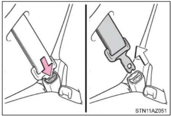
Indicates operating or working procedures. Follow the steps in numerical order.

Indicates the action (pushing, turning, etc.) used to operate switches and other devices.

Indicates the outcome of an operation (e.g. a lid opens).
natural_image
Illustration of two car seatbelt buckle diagrams showing seatbelt insertion and mounting mechanism (no text or symbols)
Indicates the component or position being explained.

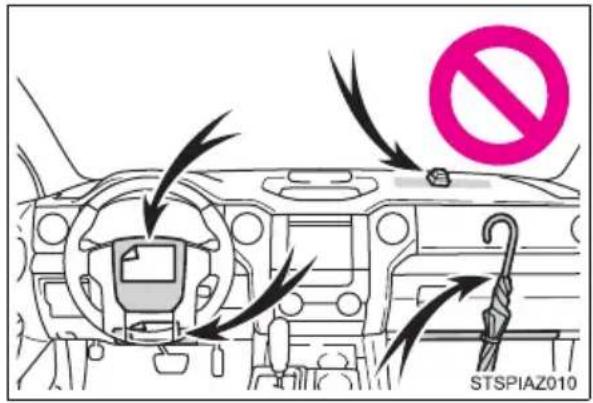
Means "Do not", "Do not do this", or "Do not let this happen".
How to search
■Searching by name
• Alphabetical index.....P. 598
■Searching by installation position
- Pictorial index.....P. 16
natural_image
Illustration of a person using a device with a lightbulb above, no text or symbols present■Searching by symptom or sound
• What to do if... (Troubleshooting) .....P. 594
natural_image
Illustration of a person reading a book with a lightbulb and electric vehicle charging nearby (no text or symbols)■Searching by title
- Table of contents......P. 2
natural_image
Illustration of a person reading an open book with a lightbulb above, symbolizing ideas or learning (no text or symbols present)Pictorial index
Exterior
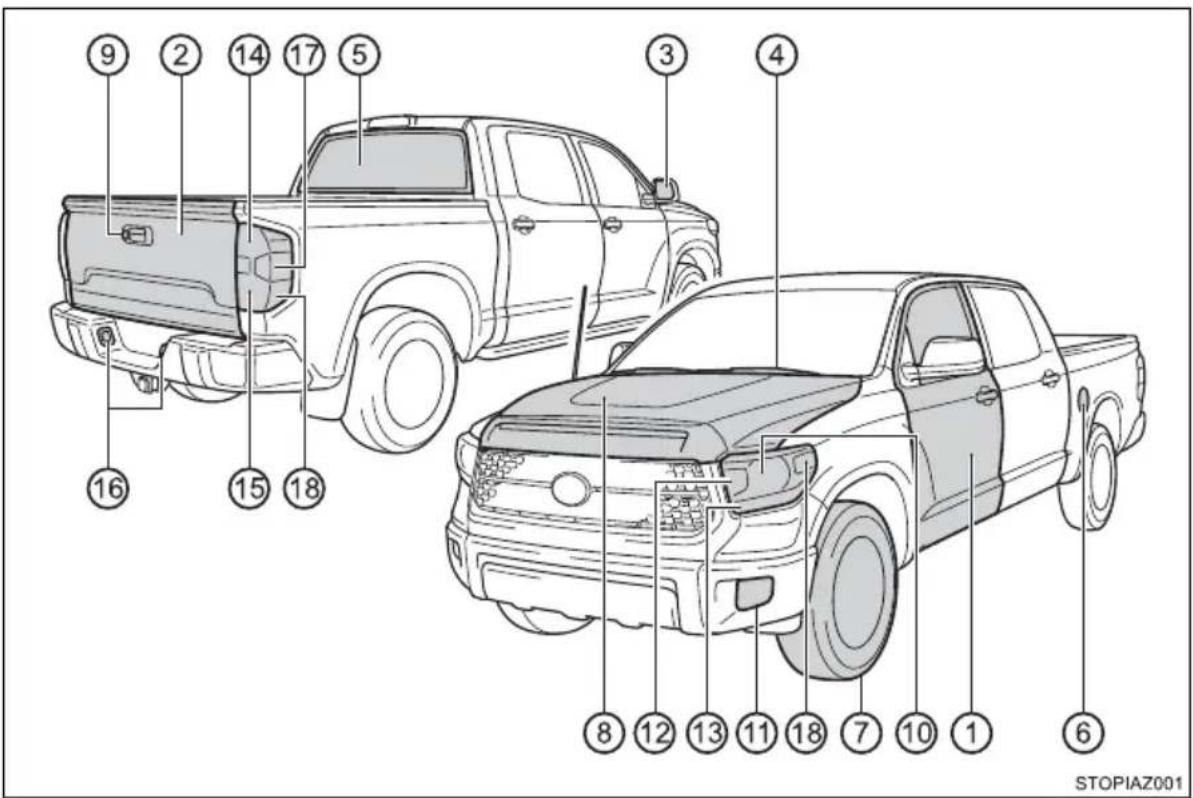
① Side doors P. 127
Locking/unlocking P. 127
Opening/closing the door glasses P. 172
Locking/unlocking by using the mechanical key ^*1 P. 523
Warning messages P. 494
② Tailgate P. 133
Locking/unlocking P. 133
Opening/closing the tailgate P. 133
Removing the tailgate P. 134
③ Outside rear view mirrors ..... P. 167
Adjusting the mirror angle P. 167
Folding the mirrors....P. 168
Driving position memory ^*2 P. 152
Defogging the mirrors ^*3 P. 342, 349
④ Windshield wipers....P. 245
Precautions against winter season P. 331
To prevent freezing (windshield wiper de-icer) ^*3 ....P. 343, 350
⑤ Back window P. 175, 176
⑥ Fuel filler door....P. 248
Refueling method....P. 248
Fuel type/fuel tank capacity P. 542
⑦ Tires P. 426
Tire size/inflation pressure P. 548
Winter tires/tire chain P. 331
Checking/rotation/tire pressure warning system . . . . . . . . . P. 426
Coping with flat tires P. 506
⑧ Hood....P. 414
Opening P. 414
Engine oil P. 543
Coping with overheat P. 529
⑨ Camera ^*4
Light bulbs of the exterior lights for driving
(Replacing method: P. 457, Watts: P. 550)
⑩ Headlights P. 234
⑪ Fog lights ^*3 P. 244
⑫ Front turn signal lights P. 232
⑬ Parking lights/daytime running lights ..... P. 234
⑭ Rear turn signal lights. P. 232
⑮ Tail lights P. 234
⑯ License plate lights P. 234
⑰ Back-up lights
Shifting the shift lever to R. P. 225
⑱ Side marker lights P. 234
^*1 : Vehicles with a smart key system
^*2 : If equipped on CrewMax models
*3: If equipped
*4: Refer to the "NAVIGATION AND MULTIMEDIA
SYSTEM OWNER'S MANUAL".
Instrument panel
Front separated type seats
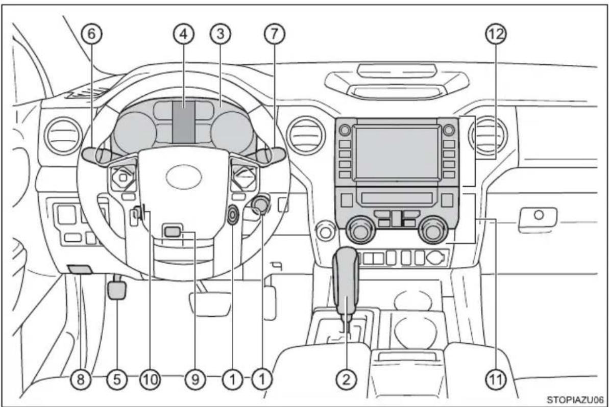
① Engine switch. P. 217
Starting the engine/changing the positions ^*1 P. 217
Starting the engine/changing the modes ^*2 P. 220
Emergency stop of the engine....P. 475
When the engine will not start....P. 521
Warning message ^*2 P. 502
② Shift lever....P. 225
Changing the shift position P. 225
Precautions against towing P. 478
When the shift lever does not move P. 229
③ Meters....P. 105
Reading the meters/adjusting the instrument panel light. . . . P. 105
Warning lights/indicator lights P. 100
When the warning lights come on....P. 485
④ Multi-information display P. 110
Display P. 110
When the warning messages are displayed ..... P. 493
⑤ Parking brake pedal....P. 233
Applying/releasing P. 233
Precautions against winter season P. 332
Warning buzzer/message P. 486, 495
⑥ Turn signal lever P. 232
Headlight switch....P.234
Headlights/parking lights/tail lights/daytime running lights P. 234
Fog lights ^*3 P. 244
⑦ Windshield wiper and washer switch P. 245
Usage P. 245
Adding washer fluid P. 425
Warning messages P. 495
⑧ Hood lock release lever....P. 414
⑨ Tilt and telescopic steering lock release lever ^*4 ..... P. 161
⑩ Tilt and telescopic steering control switch ^*5 ..... P. 162
Adjustment....P. 162
Driving position memory P. 152
⑪ Manual air conditioning system ^*3 P. 340
Automatic air conditioning system ^*3 P. 347
Usage P. 340, 347
Back window defogger ^*6 P. 342, 349
Windshield wiper de-icer ^*3 P. 343, 350
⑫ Multimedia system*7
*1: Vehicles without a smart key system
^*2 : Vehicles with a smart key system
*3: If equipped
*4: Vehicles without driving position memory
^*5 : Vehicles with driving position memory
*6: For CrewMax models
*7: Refer to the "NAVIGATION AND MULTIMEDIA
SYSTEM OWNER'S MANUAL".
▶ Front bench type seat
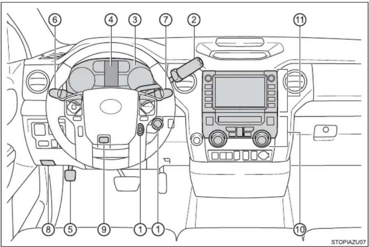
① Engine switch....P. 217
Starting the engine/changing the positions ^*1 P. 217
Starting the engine/changing the modes ^*2 P. 220
Emergency stop of the engine....P. 475
When the engine will not start....P. 521
Warning message ^*2 P. 502
② Shift lever....P. 225
Changing the shift position P. 225
Precautions against towing....P. 478
When the shift lever does not move P. 229
③ Meters....P. 105
Reading the meters/adjusting the instrument panel light. . . . P. 105
Warning lights/indicator lights P. 100
When the warning lights come on....P. 485
④ Multi-information display P. 110
Display P. 110
When the warning messages are displayed P. 493
⑤ Parking brake pedal....P. 233
Applying/releasing P. 233
Precautions against winter season P. 332
Warning buzzer/message P. 486, 495
⑥ Turn signal lever P. 232
Headlight switch....P.234
Headlights/parking lights/tail lights/ daytime running lights P. 234
Fog lights ^*3 P. 244
⑦ Windshield wiper and washer switch P. 245
Usage P. 245
Adding washer fluid P. 425
Warning lights/warning messages P. 495
⑧ Hood lock release lever....P. 414
⑨ Tilt steering lock release lever....P. 161
⑩ Manual air conditioning system ^*3 P. 340
Automatic air conditioning system ^*3 P. 347
Usage P. 340, 347
Back window defogger ^*4 P. 342, 349
Windshield wiper de-icer ^*3 P. 343, 350
⑪ Audio*3,5
Audio Plus*3,5
Premium Audio ^*3,5
Clock ^*5
*1: Vehicles without a smart key system
^*2 : Vehicles with a smart key system
*3: If equipped
*4: For CrewMax models
*5: Refer to the "NAVIGATION AND MULTIMEDIA
SYSTEM OWNER'S MANUAL".
Switches
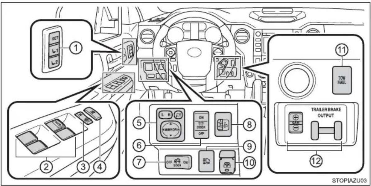
The illustration represents the instrument panel for the front separated type seat.
① Driving position memory switches ^1 P. 153
② Power window switches ^1 P. 172
③ Door lock switch ^1 P. 130
④ Window lock switch ^1 P. 172
⑤ Outside rear view mirror switches ^1 P. 167
⑥ Personal/interior lights main switch P. 357
⑦ Cargo lamp main switch....P. 359
⑧ Manual headlight leveling dial....P. 236
⑨ Automatic High Beam switch ^1 P. 239
⑩ Power back window switch ^2 P. 176
⑪ TOW/HAUL switch ^1 P. 228
⑫ Trailer brake controller ^*1 P. 327
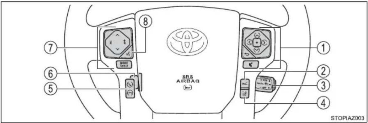
① Meter control switches P. 111
② Vehicle-to-vehicle distance switch ^*1 P. 287
③ Cruise control switch
Cruise control ^*1 P. 294
Dynamic radar cruise control ^*1 P. 280
④ LDA (Lane Departure Alert) switch ^1 P. 275
⑤ Telephone switches ^3
⑥ Tilt and telescopic steering control switch ^1 ..... P. 162
⑦ Audio remote control switches ^3
⑧ Talk switch*3
*1: If equipped
*2: For CrewMax models and if equipped on Double Cab models
*3: Refer to the "NAVIGATION AND MULTIMEDIA SYSTEM OWNER'S MANUAL".
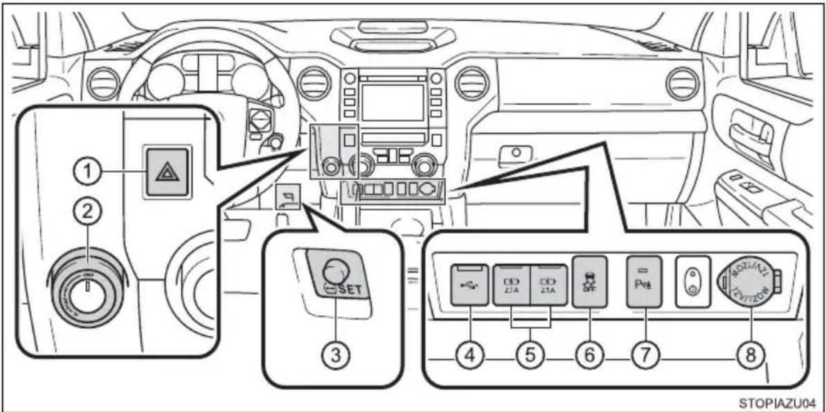
① Emergency flasher switch P. 474
② Front-wheel drive control switch* P. 315
③ Tire pressure warning reset switch....P. 428
④ USB port*2
⑤ USB charging ports P. 382
⑥ VSC off switch....P. 318, 323
⑦ Intuitive parking assist switch ^*1 P. 298
⑧ Power outlet P. 379
*1: If equipped
*2: Refer to the "NAVIGATION AND MULTIMEDIA SYSTEM OWNER'S MANUAL".
Interior
Front separated type seats
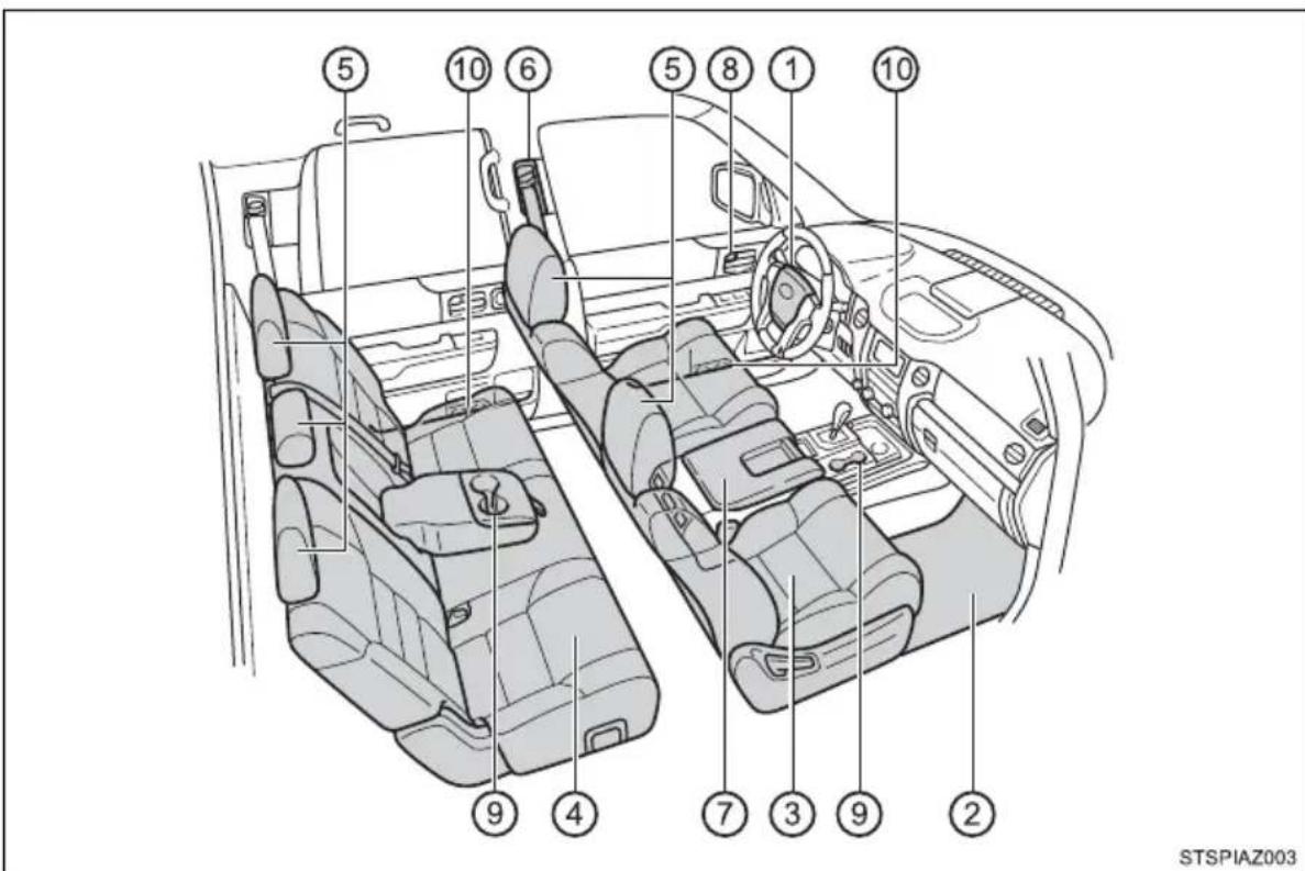
① SRS airbags P. 40
② Floor mats P. 30
③ Front seats....P. 147
④ Rear seats....P. 150
⑤ Head restraints....P. 157
⑥ Seat belts P. 34
⑦ Console box P. 363
⑧ Inside lock buttons P. 130
⑨ Cup holders....P. 370
⑩ Bottle holders. P. 372
Front bench type seat
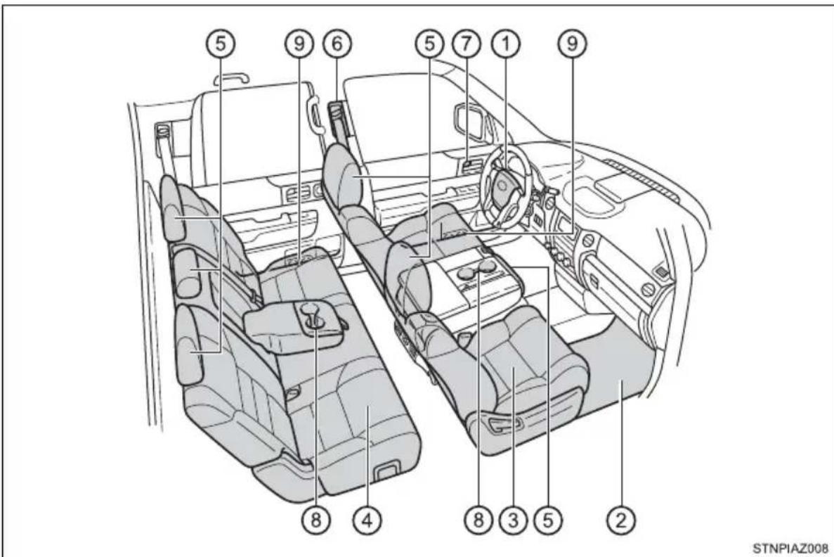
① SRS airbags P. 40
② Floor mats P. 30
③ Front seats....P. 147
④ Rear seats....P. 150
⑤ Head restraints....P. 157
⑥ Seat belts P. 34
⑦ Inside lock buttons P. 130
⑧ Cup holders....P. 370
⑨ Bottle holders....P. 372
STOPIAZU05
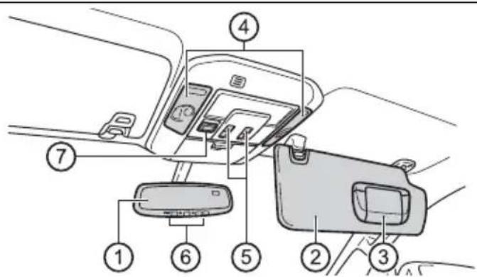
① Inside rear view mirror P. 164
② Sun visors P. 378
③ Vanity mirrors ^1 P. 378
④ Personal/interior lights ^2 P. 358
⑤ Moon roof switches ^1 P. 179
⑥ Garage door opener switches ^1 P. 385
⑦ “SOS” button ^*1 P. 79
For safety and security
1
1-1. For safe use
Before driving.... 30
For safe driving 32
Seat belts 34
SRS airbags.... 40
Front passenger occupant classification system ..... 53
Safety information for children 58
Child restraint systems...... 59
Installing child restraints..... 63
Exhaust gas precautions..... 78
1-2. Emergency assistance
Safety Connect 79
1-3. Theft deterrent system
Engine immobilizer system 85
Alarm....95
Before driving
Floor mat
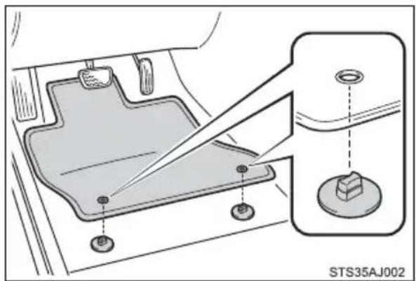
Use only floor mats designed specifically for vehicles of the same model and model year as your vehicle. Fix them securely in place onto the carpet.
1 Insert the retaining hooks (clips) into the floor mat eyelets.
natural_image
Diagram of a car interior showing a lever mechanism and a small component labeled STS35AJ002 (no text or symbols on the diagram itself)2 Turn the upper knob of each retaining hook (clip) to secure the floor mats in place.
*: Always align the marks.
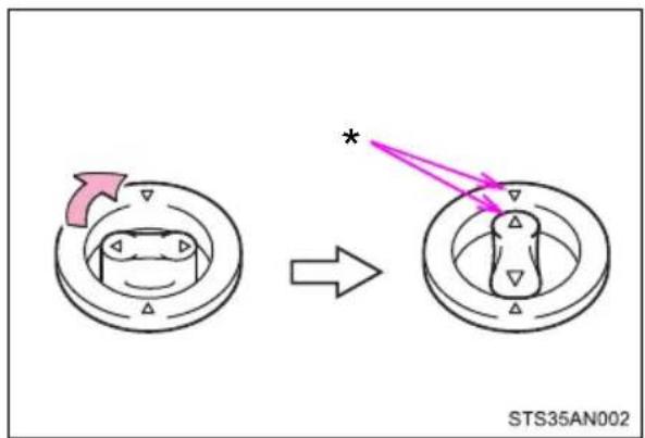
The shape of the retaining hooks (clips) may differ from that shown in the illustration.

WARNING
Observe the following precautions.
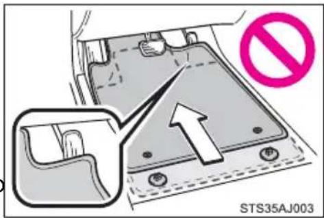
Failure to do so may cause the driver's floor mat to slip, possibly interfering with the pedals while driving. An unexpectedly high speed may result or it may become difficult to stop the vehicle. This could lead to an accident, resulting in death or serious injury.
When installing the driver's floor mat
- Do not use floor mats designed for other models or different model year vehicles, even if they are Toyota Genuine floor mats.
- Only use floor mats designed for the driver's seat.
● Always install the floor mat securely using the retaining hooks (clips) provided. - Do not use two or more floor mats on top of each other.
- Do not place the floor mat bottom-side up or upside-down.
Before driving
- Check that the floor mat is securely fixed in the correct place with all the provided retaining hooks (clips). Be especially careful to perform this check after cleaning the floor.
With the engine stopped and the shift lever in P, fully depress each pedal to the floor to make sure it does not interfere with the floor mat.
For safe driving
For safe driving, adjust the seat and mirror to an appropriate position before driving.
Correct driving posture
① Adjust the angle of the seat-back so that you are sitting straight up and so that you do not have to lean forward to steer. (→P. 147)
② Adjust the seat so that you can depress the pedals fully and so that your arms bend slightly at the elbow when gripping the steering wheel. (→P. 147)
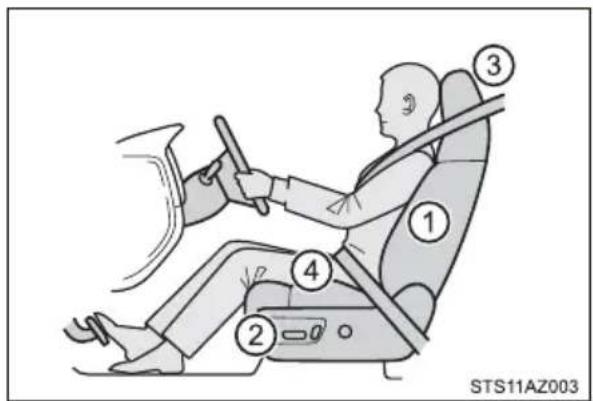
③ Lock the head restraint in place with the center of the head restraint closest to the top of your ears. (→P. 157)
④ Wear the seat belt correctly. (→P. 34)
Correct use of the seat belts
Make sure that all occupants are wearing their seat belts before driving the vehicle. (→P. 34)
Use a child restraint system appropriate for the child until the child becomes large enough to properly wear the vehicle's seat belt. ( P. 59)
Adjusting the mirrors
Make sure that you can see backward clearly by adjusting the inside and outside rear view mirrors properly. ( P. 164, 167)

WARNING
Observe the following precautions.
Failure to do so may result in death or serious injury.
- Do not adjust the position of the driver's seat while driving.
Doing so could cause the driver to lose control of the vehicle. - Do not place a cushion between the driver or passenger and the seatback.
A cushion may prevent correct posture from being achieved, and reduce the effectiveness of the seat belt and head restraint. - Do not place anything under the front seats.
Objects placed under the front seats may become jammed in the seat tracks and stop the seat from locking in place. This may lead to an accident and the adjustment mechanism may also be damaged.
●Always observe the legal speed limit when driving on public roads. - When driving over long distances, take regular breaks before you start to feel tired.
Also, if you feel tired or sleepy while driving, do not force yourself to continue driving and take a break immediately.
Seat belts
Make sure that all occupants are wearing their seat belts before driving the vehicle.
Correct use of the seat belts
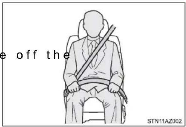
●Extend the shoulder belt so that it comes fully over the shoulder, but does not come into contact with the neck or slid shoulder.
●Position the lap belt as low as possible over the hips.
- Adjust the position of the seat-back. Sit up straight and well back in the seat.
●Do not twist the seat belt.
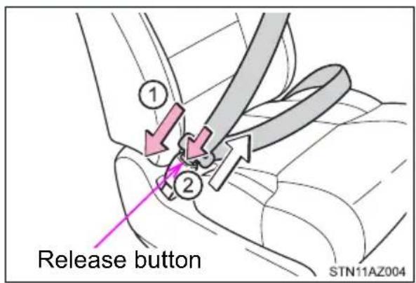
Fastening and releasing the seat belt
① To fasten the seat belt, push the plate into the buckle until a click sound is heard.
② To release the seat belt, press the release button.
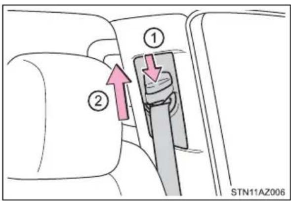
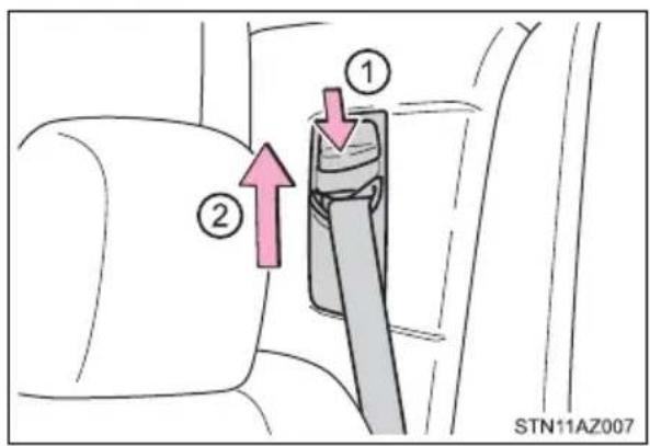
Adjusting the seat belt shoulder anchor height
① Push the seat belt shoulder anchor down while pressing the release button.
② Push the seat belt shoulder anchor up.
Move the height adjuster up and down as needed until you hear a click.
▶ Front seats ▶ Rear seats (CrewMax models)
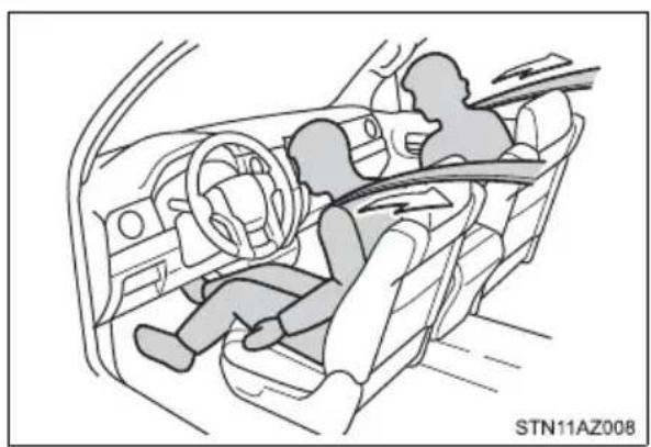
Seat belt pretensioners (front seats)
The pretensioners help the seat belts to quickly restrain the occupants by retracting the seat belts when the vehicle is subjected to certain types of severe frontal or side collision or a vehicle rollover.
The pretensioners do not activate in the event of a minor frontal impact, a minor side impact or a rear impact.
natural_image
Interior view of a car showing two people seated in the driver's seat, with dashboard and steering wheel visible (no text or symbols)Emergency locking retractor (ELR)
The retractor will lock the belt during a sudden stop or on impact. It may also lock if you lean forward too quickly. A slow, easy motion will allow the belt to extend so that you can move around fully.
■Automatic locking retractor (ALR)
When a passenger's shoulder belt is completely extended and then retracted even slightly, the belt is locked in that position and cannot be extended. This feature is used to hold the child restraint system (CRS) firmly. To free the belt again, fully retract the belt and then pull the belt out once more. (→P. 63)
■Child seat belt usage
The seat belts of your vehicle were principally designed for persons of adult size.
Use a child restraint system appropriate for the child, until the child becomes large enough to properly wear the vehicle's seat belt. (→P. 59)
- When the child becomes large enough to properly wear the vehicle's seat belt, follow the instructions regarding seat belt usage. (→P. 34)
■Replacing the belt after the pretensioner has been activated
If the vehicle is involved in multiple collisions, the pretensioner will activate for the first collision, but will not activate for the second or subsequent collisions.
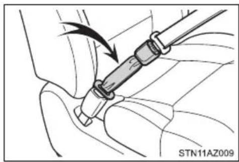
■Seat belt extender
If your seat belts cannot be fastened securely because they are not long enough, a personalized seat belt extender is available from your Toyota dealer free of charge.
natural_image
Medical procedure illustration showing a surgical tool interacting with a patient's arm (no text or symbols present)
WARNING
Observe the following precautions to reduce the risk of injury in the event of sudden braking, sudden swerving or an accident.
Failure to do so may cause death or serious injury.
■Wearing a seat belt
●Ensure that all passengers wear a seat belt.
●Always wear a seat belt properly.
● Each seat belt should be used by one person only. Do not use a seat belt for more than one person at once, including children.
Toyota recommends that children be seated in the rear seat and always use a seat belt and/or an appropriate child restraint system.
● To achieve a proper seating position, do not recline the seat more than necessary. The seat belt is most effective when the occupants are sitting up straight and well back in the seats.
●Do not wear the shoulder belt under your arm.
●Always wear your seat belt low and snug across your hips.
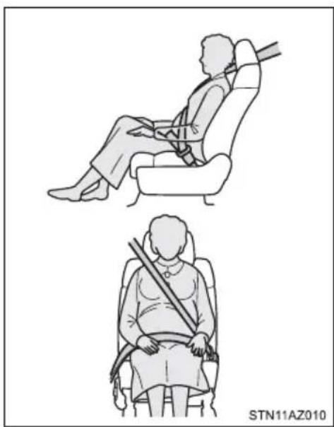
■ Pregnant women
Obtain medical advice and wear the seat belt in the proper way. (→P. 34)
Women who are pregnant should position the lap belt as low as possible over the hips in the same manner as other occupants, extending the shoulder belt completely over the shoulder and avoiding belt contact with the rounding of the abdominal area.
If the seat belt is not worn properly, not only the pregnant woman, but also the fetus could suffer death or serious injury as a result of sudden braking or a collision.
natural_image
Illustration of a person seated in two different positions, one using a seatbelt and the other holding a shoulder (no text or symbols)■People suffering illness
Obtain medical advice and wear the seat belt in the proper way. (→P. 34)

WARNING
■When children are in the vehicle
Do not allow children to play with the seat belt. If the seat belt becomes twisted around a child's neck, it may lead to choking or other serious injuries that could result in death.
If this occurs and the buckle cannot be unfastened, scissors should be used to cut the belt.
■Seat belt pretensioners
- Do not place anything, such as a cushion, on the front passenger's seat. Doing so will disperse the passenger's weight, which prevents the sensor from detecting the passenger's weight properly. As a result, the seat belt pretensioner for the front passenger's seat may not activate in the event of a collision.
- If the pretensioner has activated, the SRS warning light will come on. In that case, the seat belt cannot be used again and must be replaced at your Toyota dealer.
■Adjustable shoulder anchor
Always make sure the shoulder belt is positioned across the center of your shoulder. The belt should be kept away from your neck, but not falling off your shoulder. Failure to do so could reduce the amount of protection in an accident and cause death or serious injuries in the event of a sudden stop, sudden swerve or an accident. (→P. 35)
■Seat belt damage and wear
- Do not damage the seat belts by allowing the belt, plate, or buckle to be jammed in the door.
- Inspect the seat belt system periodically. Check for cuts, fraying, and loose parts. Do not use a damaged seat belt until it is replaced. Damaged seat belts cannot protect an occupant from death or serious injury.
- Ensure that the belt and plate are locked and the belt is not twisted. If the seat belt does not function correctly, immediately contact your Toyota dealer.
- Replace the seat assembly, including the belts, if your vehicle has been involved in a serious accident, even if there is no obvious damage.
- Do not attempt to install, remove, modify, disassemble or dispose of the seat belts. Have any necessary repairs carried out by your Toyota dealer. Inappropriate handling of the pretensioner may prevent it from operating properly, resulting in death or serious injury.

WARNING
■ Using a seat belt extender
- Do not wear the seat belt extender if you can fasten the seat belt without the extender.
- Do not use the seat belt extender when installing a child restraint system because the belt will not securely hold the child restraint system, increasing the risk of death or serious injury in the event of an accident.
●The personalized extender may not be safe on another vehicle, when used by another person, or at a different seating position other than the one originally intended.

NOTICE
■When using a seat belt extender
When releasing the seat belt, press on the buckle release button on the extender, not on the seat belt.
This helps prevent damage to the vehicle interior and the extender itself.
SRS airbags
The SRS airbags inflate when the vehicle is subjected to certain types of severe impacts that may cause significant injury to the occupants. They work together with the seat belts to help reduce the risk of death or serious injury.
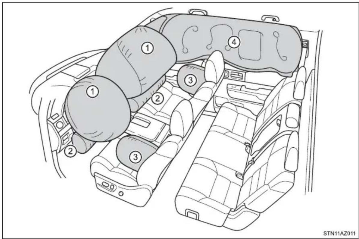
◆ SRS front airbags
① SRS driver airbag/front passenger airbag
Can help protect the head and chest of the driver and right front passenger from impact with interior components
② SRS knee airbags
Can help provide driver and front passenger protection
◆ SRS side and curtain shield airbags
③ SRS side airbags Can help protect the torso of the front seat occupants
④ SRS curtain shield airbags
● Can help protect primarily the head of occupants in the outer seats
●Can help prevent the occupants from being thrown from the vehicle in the event of vehicle rollover
SRS airbag system components
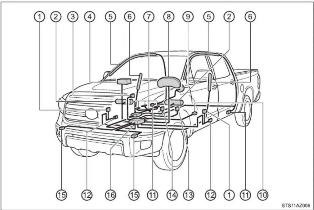
① Seat belt pretensioners
② Knee airbags
③ “AIR BAG ON” and “AIR BAG OFF” indicator lights
④ Front passenger airbag
⑤ Curtain shield airbags
⑥ Side airbags (front seats)
⑦ Front passenger occupant classification system (ECU and sensors)
⑧ SRS warning light
⑨ Driver airbag
⑩ Driver's seat position sensor
⑪ Side impact sensors (rear)
⑫ Side impact sensors (front door)
⑬ Driver's seat belt buckle switch
⑭ Front passenger's seat belt buckle switch
⑮ Front impact sensors
⑯ Airbag sensor assembly
Your vehicle is equipped with ADVANCED AIRBAGS designed based on the US motor vehicle safety standards (FMVSS208). The airbag sensor assembly (ECU) controls airbag deployment based on information obtained from the sensors etc. shown in the system components diagram above. This information includes crash severity and occupant information. As the airbags deploy, a chemical reaction in the inflators quickly fills the airbags with non-toxic gas to help restrain the motion of the occupants.
Front bench type seat: The SRS airbags are designed to protect the driver and right front passenger, and they are not designed to protect an occupant in the front center seating position.

WARNING
■SRS airbag precautions
Observe the following precautions regarding the SRS airbags. Failure to do so may cause death or serious injury.
● The driver and all passengers in the vehicle must wear their seat belts properly. The SRS airbags are supplemental devices to be used with the seat belts.
●The SRS driver airbag deploys with considerable force, and can cause death or serious injury especially if the driver is very close to the airbag. The National Highway Traffic Safety Administration (NHTSA) advises:
Since the risk zone for the driver's airbag is the first 2 - 3 in. (50 - 75 mm) of inflation, placing yourself 10 in. (250 mm) from your driver airbag provides you with a clear margin of safety. This distance is measured from the center of the steering wheel to your breastbone. If you sit less than 10 in. (250 mm) away now, you can change your driving position in several ways:
- Move your seat to the rear as far as you can while still reaching the pedals comfortably.
- Slightly recline the back of the seat.
Although vehicle designs vary, many drivers can achieve the 10 in. (250 mm) distance, even with the driver seat all the way forward, simply by reclining the back of the seat somewhat. If reclining the back of your seat makes it hard to see the road, raise yourself by using a firm, non-slippery cushion, or raise the seat if your vehicle has that feature.
- If your steering wheel is adjustable, tilt it downward. This points the airbag toward your chest instead of your head and neck.
The seat should be adjusted as recommended by NHTSA above, while still maintaining control of the foot pedals, steering wheel, and your view of the instrument panel controls.
- If the seat belt extender has been connected to the front seat belt buckles but the seat belt extender has not also been fastened to the latch plate of the seat belt, the SRS front airbags will judge that the driver and front passenger are wearing the seat belt even though the seat belt has not been connected. In this case, the SRS front airbags may not activate correctly in a collision, resulting in death or serious injury in the event of a collision. Be sure to wear the seat belt with the seat belt extender.
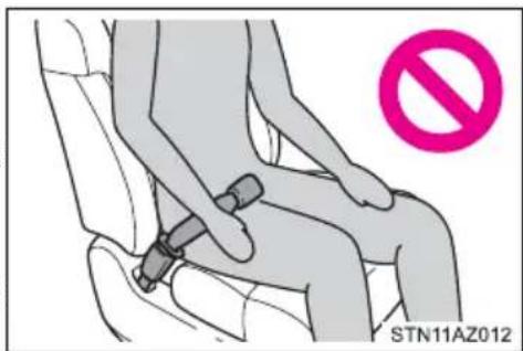

WARNING
■SRS airbag precautions
The SRS front passenger airbag also deploys with considerable force, and can cause death or serious injury especially if the front passenger is very close to the airbag. The front passenger seat should be as far from the airbag as possible with the seatback adjusted, so the front passenger sits upright.
- Improperly seated and/or restrained infants and children can be killed or seriously injured by a deploying airbag. An infant or child who is too small to use a seat belt should be properly secured using a child restraint system. Toyota strongly recommends that all infants and children be placed in the rear seats of the vehicle and properly restrained. The rear seats are safer for infants and children than the front passenger seat. (→P. 59)
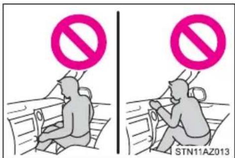
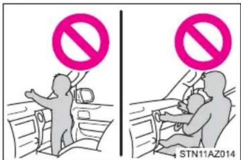
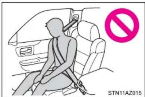
- Do not sit on the edge of the seat or lean against the dashboard.
- Do not allow a child to stand in front of the SRS front passenger airbag unit or sit on the knees of a front passenger.
- Do not allow the front seat occupants to hold items on their knees.
- Do not lean against the door, the roof side rail or the front, side and rear pillars.

WARNING
■SRS airbag precautions
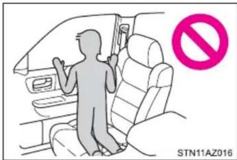
- Do not allow anyone to kneel on the passenger seats toward the door or put their head or hands outside the vehicle.
- Do not attach anything to or lean anything against areas such as the dashboard, steering wheel pad and lower portion of the instrument panel. These items can become projectiles when the SRS driver, front passenger and knee airbags deploy.
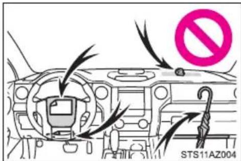
- Do not attach anything to areas such as a door, windshield glass, side door glass, front or rear pillar, roof side rail and assist grip.
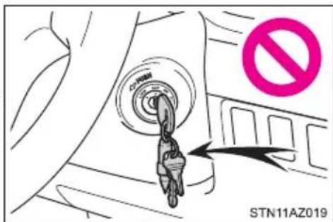
- Do not attach any heavy, sharp or hard objects such as keys and accessories to the key. The objects may restrict the SRS knee airbag inflation or be thrust into the driver's seat area by the force of the deploying airbag, thus causing a danger.
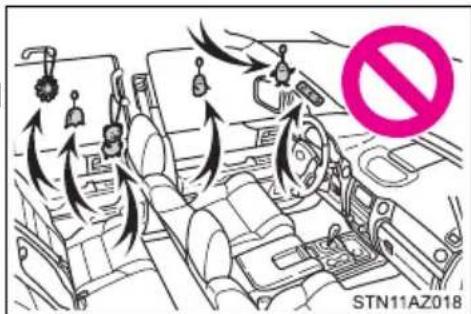
- Do not hang coat hangers or other hard objects on the coat hooks. All of these items could become projectiles and may cause death or serious injury, should the SRS curtain shield airbags deploy.
- If a vinyl cover is put on the area where the SRS knee airbag will deploy, be sure to remove it.

WARNING
■SRS airbag precautions
- Do not use seat accessories which cover the parts where the SRS side airbags inflate as they may interfere with inflation of the airbags. Such accessories may prevent the side airbags from activating correctly, disable the system or cause the side airbags to inflate accidentally, resulting in death or serious injury.
- Do not strike or apply significant levels of force to the area of the SRS airbag components. Doing so can cause the SRS airbags to malfunction.
- Do not touch any of the component parts immediately after the SRS airbags have deployed (inflated) as they may be hot.
- If breathing becomes difficult after the SRS airbags have deployed, open a door or window to allow fresh air in, or leave the vehicle if it is safe to do so. Wash off any residue as soon as possible to prevent skin irritation.
- If the areas where the SRS airbags are stored, such as the steering wheel pad and front and rear pillar garnishes, are damaged or cracked, have them replaced by your Toyota dealer.
- Do not place anything, such as a cushion, on the front passenger's seat. Doing so will disperse the passenger's weight, which prevents the sensor from detecting the passenger's weight properly. As a result, the SRS front airbags for the front passenger may not deploy in the event of a collision.
■Modification and disposal of SRS airbag system components
Do not dispose of your vehicle or perform any of the following modifications without consulting your Toyota dealer. The SRS airbags may malfunction or deploy (inflate) accidentally, causing death or serious injury.
● Installation, removal, disassembly and repair of the SRS airbags
● Repairs, modifications, removal or replacement of the steering wheel, instrument panel, dashboard, seats or seat upholstery, front, side and rear pillars or roof side rails
● Repairs or modifications of the front fender, front bumper, or side of the occupant compartment
● Installation of a grille guard (bull bars, kangaroo bar, etc.), snow plows, winches or roof luggage carrier
Modifications to the vehicle's suspension system
● Installation of electronic devices such as mobile two-way radios and CD players
● Modifications to your vehicle for a person with a physical disability
■If the SRS airbags deploy (inflate)
- Slight abrasions, burns, bruising etc., may be sustained from SRS airbags, due to the extremely high speed deployment (inflation) by hot gases.
●A loud noise and white powder will be emitted.
● Parts of the airbag module (steering wheel hub, airbag cover and inflator) as well as the front seats, parts of the front and rear pillars and roof side rails, may be hot for several minutes. The airbag itself may also be hot.
●The windshield may crack.
●The emergency flashers will turn on automatically. (→P. 474)
For Safety Connect subscribers, if the SRS airbags deploy or in the event of a severe rear-end collision, the system is designed to send an emergency call to the response center, notifying them of the vehicle's location (without needing to push the "SOS" button) and an agent will attempt to speak with the occupants to ascertain the level of emergency and assistance required. If the occupants are unable to communicate, the agent automatically treats the call as an emergency and helps to dispatch the necessary emergency services. (→P. 79) - An SRS airbag is deployed.
- A seat belt pretensioner is activated.
- The vehicle is involved in a severe rear-end collision.
■ SRS airbag deployment conditions (SRS front airbags)
- The SRS front airbags will deploy in the event of an impact that exceeds the set threshold level (the level of force corresponding to an approximately 12 - 18 mph [20 - 30 km/h] frontal collision with a fixed wall that does not move or deform).
However, this threshold velocity will be considerably higher in the following situations:
- If the vehicle strikes an object, such as a parked vehicle or sign pole, which can move or deform on impact
- If the vehicle is involved in an underride collision, such as a collision in which the front of the vehicle “underrides”, or goes under, the bed of a truck
● Depending on the type of collision, it is possible that only the seat belt pretensioners will activate. - The SRS front airbags for the front passenger will not activate if there is no passenger sitting in the right front passenger seat. However, the SRS front airbags for the front passenger may deploy if luggage is put in the seat, even if the seat is unoccupied. (→P. 53)
■ SRS airbag deployment conditions (SRS side and curtain shield airbags)
- The SRS side and curtain shield airbags will deploy in the event of an impact that exceeds the set threshold level (the level of force corresponding to the impact force produced by an approximately 3300 lb. [1500 kg] vehicle colliding with the vehicle cabin from a direction perpendicular to the vehicle orientation at an approximate speed of 12 - 18 mph [20 - 30 km/h]).
● The SRS curtain shield airbags will deploy in the event of vehicle rollover.
● The SRS curtain shield airbags may also deploy in the event of a severe frontal collision.
■ Conditions under which the SRS airbags may deploy (inflate), other than a collision
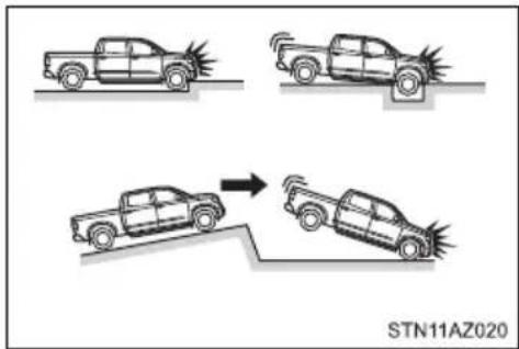
The SRS front airbags and SRS curtain shield airbags may also deploy if a serious impact occurs to the underside of your vehicle. Some examples are shown in the illustration.
●Hitting a curb, edge of pavement or hard surface
●Falling into or jumping over a deep hole
●Landing hard or vehicle falling
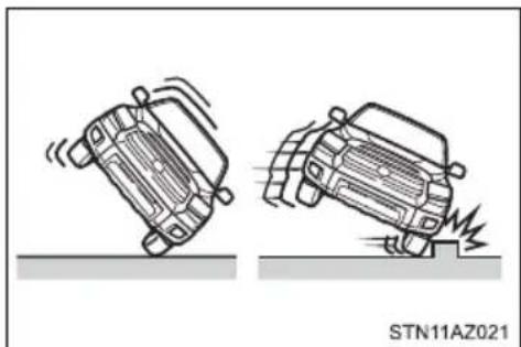
The SRS curtain shield airbags may also deploy under the situation shown in the illustration.
●The angle of vehicle tip-up is marginal.
●The vehicle skids and hits a curb stone.
natural_image
Two cartoon-style cars on a surface, one falling and one partially submerged (no text or symbols)■ Types of collisions that may not deploy the SRS airbags (SRS front airbags)
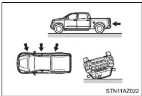
The SRS front airbags do not generally inflate if the vehicle is involved in a side or rear collision, if it rolls over, or if it is involved in a low-speed frontal collision. But, whenever a collision of any type causes sufficient forward deceleration of the vehicle, deployment of the SRS front airbags may occur.
●Collision from the side
- Collision from the rear
● Vehicle rollover
natural_image
Diagram showing three car under collision scenarios with arrows indicating motion (no text or symbols)■Types of collisions that may not deploy the SRS airbags (SRS side and curtain shield airbags)
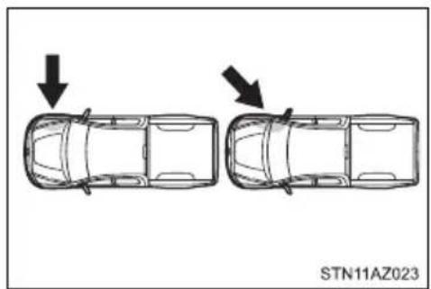
The SRS side and curtain shield airbags may not activate if the vehicle is subjected to a collision from the side at certain angles, or a collision to the side of the vehicle body other than the passenger compartment.
●Collision from the side to the vehicle body other than the passenger compartment
- Collision from the side at an angle
natural_image
Top-down diagram of two car rear seats with arrows indicating direction (no text or symbols on the car itself)The SRS side airbags do not generally inflate if the vehicle is involved in a frontal or rear collision, if it rolls over, or if it is involved in a low-speed side collision.
●Collision from the front
- Collision from the rear
●Vehicle rollover
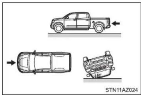
natural_image
Top-down diagram of a pickup truck showing three views of the vehicle (no text or symbols on the diagram itself)The SRS curtain shield airbags do not generally inflate if the vehicle is involved in a rear collision, if it pitches end over end, or if it is involved in a low-speed side or low-speed frontal collision.
- Collision from the rear
● Pitching end over end
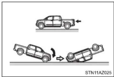
■When to contact your Toyota dealer
In the following cases, the vehicle will require inspection and/or repair. Contact your Toyota dealer as soon as possible.
●Any of the SRS airbags have been inflated.
●The front of the vehicle is damaged or deformed, or was involved in an accident that was not severe enough to cause the SRS front airbags to inflate.
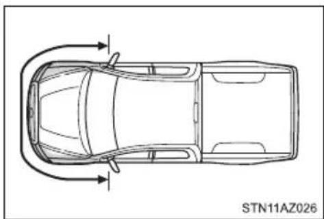
natural_image
Top-down line drawing of a car showing side and top views with directional arrows (no text or symbols)● A portion of a door or its surrounding area is damaged or deformed, or the vehicle was involved in an accident that was not severe enough to cause the SRS side and curtain shield airbags to inflate.
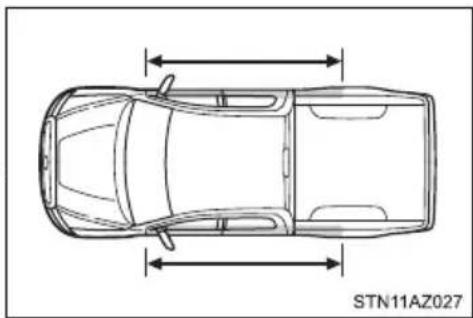
natural_image
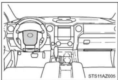
Top-down line drawing of a car with horizontal double-headed arrows indicating vertical motion (no text or symbols on the car itself)●The pad section of the steering wheel, dashboard near the front passenger air-bag or lower portion of the instrument panel is scratched, cracked, or otherwise damaged.
natural_image
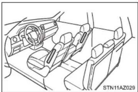
Front view line drawing of a vehicle dashboard and steering wheel (no text or symbols)●The surface of the seats with the side airbag is scratched, cracked, or otherwise damaged.
natural_image
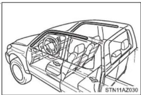
Line drawing of a car interior showing dashboard, steering wheel, and seat compartments (no text or symbols)●The portion of the front pillars, rear pillars or roof side rail garnishes (padding) containing the curtain shield airbags inside is scratched, cracked, or otherwise damaged.
natural_image
Line drawing of a car interior showing dashboard, steering wheel, and driver seat (no text or symbols)Front passenger occupant classification system
Your vehicle is equipped with a front passenger occupant classification system. This system detects the conditions of the front passenger seat and activates or deactivates the front passenger airbag, front passenger knee airbag and front passenger's seat belt pretensioner.
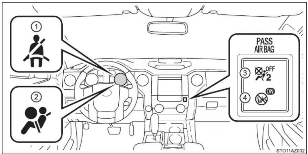
① Seat belt reminder light
② SRS warning light
③ “AIR BAG OFF” indicator light
④ “AIR BAG ON” indicator light
Condition and operation in the front passenger occupant classification system
■Adult* 1
| Indicator/warning light | “AIR BAG ON” and “AIR BAG OFF” indicator lights | “AIR BAG ON” |
| SRS warning light Off | ||
| Front passenger's seat belt reminder light | Off^*2 or flashing^*3 | |
| Devices | Front passenger airbag | ActivatedFront passe |
| Front passenger's seat belt pretensioner |
■Child* 4 or child restraint system*5
| Indicator/warning light | “AIR BAG ON” and “AIR BAG OFF” indicator lights | “AIR BAG OFF”*6 |
| SRS warning light Off | ||
| Front passenger's seat belt reminder light | Off*2or flashing*3 | |
| Devices | Front passenger airbag | Deactivated |
| Front passenger knee airbag | ||
| Front passenger's seat belt pretensioner | Activated |
Unoccupied
| Indicator/warning light | “AIR BAG ON” and “AIR BAG OFF” indicator lights | Not illuminated |
| SRS warning light | Off | |
| Front passenger's seat belt reminder light | ||
| Devices | Front passenger airbag | Deactivated |
| Front passenger knee airbag | ||
| Front passenger's seat belt pretensioner | Activated^*7 or deactivated^*8 |
■There is a malfunction in the system
| Indicator/warning light | “AIR BAG ON” and “AIR BAG OFF” indicator lights | “AIR BAG OFF” |
| SRS warning light | On | |
| Front passenger's seat belt reminder light | ||
| Devices | Front passenger airbag | Deactivated |
| Front passenger knee airbag | ||
| Front passenger's seat belt pretensioner | Activated |
*1: The system judges a person of adult size as an adult. When a smaller adult sits in the front passenger seat, the system may recognize him/her as a child depending on his/her physique and posture.
*2: In the event the front passenger is wearing a seat belt
*3: In the event the front passenger does not wear a seat belt
*4: When a larger child who has outgrown a child restraint system sits in the front passenger seat, the system may recognize him/her as an adult depending on his/her physique or posture.
*5: Never install a rear-facing child restraint system on the front passenger seat. A forward-facing child restraint system should only be installed on the front passenger seat when it is unavoidable. (→P. 59)
*6: In case the indicator light is not illuminated, consult this manual on how to install the child restraint system properly. (→P. 63)
*7: In the event of a side collision.
*8: In the event of a frontal collision or rollover.

WARNING
■Front passenger occupant classification system precautions
Observe the following precautions regarding the front passenger occupant classification system.
Failure to do so may cause death or serious injury.
●Wear the seat belt properly.
Make sure the front passenger's seat belt plate has not been left inserted into the buckle before someone sits in the front passenger seat.
Make sure the “AIR BAG OFF” indicator light is not illuminated when using the seat belt extender for the right front passenger seat. If the “AIR BAG OFF” indicator light is illuminated, disconnect the extender tongue from the seat belt buckle, and reconnect the seat belt. Reconnect the seat belt extender after making sure the “AIR BAG ON” indicator light is illuminated. If you use the seat belt extender while the “AIR BAG OFF” indicator light is illuminated, the SRS airbags for the front passenger will not activate, which could cause death or serious injury in the event of a collision.
- Do not apply a heavy load to the front passenger seat or equipment (e.g. seatback pockets).
- Do not put weight on the front passenger seat by putting your hands or feet on the front passenger seat seatback from the rear passenger seat.
- Do not let a rear passenger lift the front passenger seat with their feet or press on the seatback with their legs.
- Do not put objects under the front passenger seat.

WARNING
■Front passenger occupant classification system precautions
- Do not recline the front passenger seatback so far that it touches a rear seat. This may cause the “AIR BAG OFF” indicator light to be illuminated, which indicates that the SRS airbags for the front passenger will not activate in the event of a severe accident. If the seatback touches the rear seat, return the seatback to a position where it does not touch the rear seat. Keep the front passenger seatback as upright as possible when the vehicle is moving. Reclining the seatback excessively may lessen the effectiveness of the seat belt system.
- If an adult sits in the front passenger seat, the “AIR BAG ON” indicator light is illuminated. If the “AIR BAG OFF” indicator is illuminated, ask the passenger to sit up straight, well back in the seat, feet on the floor, and with the seat belt worn correctly. If the “AIR BAG OFF” indicator still remains illuminated, either ask the passenger to move to the rear seat, or if that is not possible, move the front passenger seat fully rearward.
- When it is unavoidable to install a forward-facing child restraint system on the front passenger seat, install the child restraint system on the front passenger seat in the proper order. (→P. 63)
- Do not modify or remove the front seats.
- Do not kick the front passenger seat or subject it to severe impact. Otherwise, the SRS warning light may come on to indicate a malfunction of the front passenger occupant classification system. In this case, contact your Toyota dealer immediately.
● Child restraint systems installed on the rear seat should not contact the front seatbacks. - Do not use a seat accessory, such as a cushion and seat cover, that covers the seat cushion surface.
- Do not attach a commercial seatback table or other heavy item to the back of the front passenger seat.
- Do not modify or replace the upholstery of the front seat.
Safety information for children
Observe the following precautions when children are in the vehicle.
Use a child restraint system appropriate for the child, until the child becomes large enough to properly wear the vehicle's seat belt.
●Double Cab and CrewMax models: It is recommended that children sit in the rear seats to avoid accidental contact with the shift lever, wiper lever, etc.
- Use the rear door child-protector lock or the window lock switch (if equipped) to avoid children opening the door while driving or operating the power window accidentally.
- Do not let small children operate equipment which may catch or pinch body parts, such as the power window, hood, tailgate, seats, etc.

WARNING
Never leave children unattended in the vehicle, and never allow children to have or use the key.
Children may be able to start the vehicle or shift the vehicle into neutral. There is also a danger that children may injure themselves by playing with the windows, the moon roof or other features of the vehicle. In addition, heat build-up or extremely cold temperatures inside the vehicle can be fatal to children.
Child restraint systems
A child restraint system for a small child or baby must itself be properly restrained on the seat with the lap portion of the lap/shoulder belt.
The laws of all 50 states of the U.S.A. and Canada now require the use of child restraint systems.
Points to remember
Studies have shown that installing a child restraint on a rear seat is much safer than installing one on the front passenger seat.
- Choose a child restraint system that suits your vehicle and is appropriate to the age and size of the child.
- For installation details, follow the instructions provided with the child restraint system.
General installation instructions are provided in this manual. (→P. 63)
Types of child restraints
Child restraint systems are classified into the following 3 types according to the age and size of the child:
▶ Rear facing — Infant seat/convertible seat
Forward facing — Convertible seat
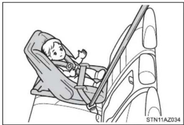
natural_image
Illustration of a child in a car seatbelt inside a vehicle, no text or symbols present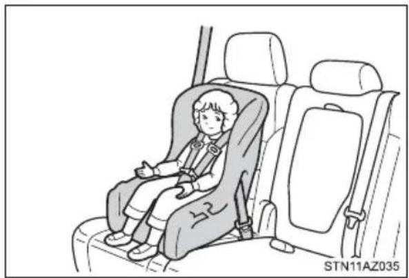
natural_image
Illustration of a child seated in a car seat, no text or symbols present▶ Booster seat
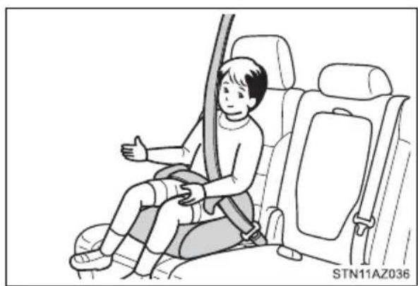
natural_image
Illustration of a child sitting in a car seat, giving a thumbs-up gesture (no text or symbols present)■Selecting an appropriate child restraint system
- Use a child restraint system appropriate for the child until the child becomes large enough to properly wear the vehicle's seat belt.
- If the child is too large for a child restraint system, sit the child on a rear seat and use the vehicle's seat belt. ( P. 34)

WARNING
■Child restraint precautions
For effective protection in automobile accidents and sudden stops, a child must be properly restrained, using a seat belt or child restraint system depending on the age and size of the child. Holding a child in your arms is not a substitute for a child restraint system. In an accident, the child can be crushed against the windshield, or between you and the vehicle's interior.
Toyota strongly urges the use of a proper child restraint system that conforms to the size of the child, installed on the rear seat. According to accident statistics, the child is safer when properly restrained in the rear seat than in the front seat.
- Never install a rear-facing child restraint system on the front passenger seat even if the “AIR BAG OFF” indicator light is illuminated.
In the event of an accident, the force of the rapid inflation of the front passenger airbag can cause death or serious injury to the child if the rear-facing child restraint system is installed on the front passenger seat.
A forward-facing child restraint system may be installed on the front passenger seat only when it is unavoidable. A child restraint system that requires a top tether strap should not be used in the front passenger seat since there is no top tether strap anchor for the front passenger seat. Adjust the seatback as upright as possible and always move the seat as far back as possible even if the "AIR BAG OFF" indicator light is illuminated, because the front passenger airbag could inflate with considerable speed and force. Otherwise, the child may be killed or seriously injured.

WARNING
■Child restraint precautions
- Do not use the seat belt extender when installing a child restraint system on the front or rear passenger seat. If installing a child restraint system with the seat belt extender connected to the seat belt, the seat belt will not securely hold the child restraint system, which could cause death or serious injury to the child or other passengers in the event of an accident.
- Do not allow the child to lean his/her head or any part of his/her body against the door or the area of the seat, front and rear pillars or roof side rails from which the SRS side airbags or SRS curtain shield airbags deploy even if the child is seated in the child restraint system. It is dangerous if the SRS side airbags and curtain shield airbags inflate, and the impact could cause death or serious injury to the child.
Make sure you have complied with all installation instructions provided by the child restraint manufacturer and that the system is properly secured. If it is not secured properly, it may cause death or serious injury to the child in the event of a sudden stop or an accident.
■When children are in the vehicle
Do not allow children to play with the seat belt. If the seat belt becomes twisted around a child's neck, it may lead to choking or other serious injuries that could result in death.
If this occurs and the buckle cannot be unfastened, scissors should be used to cut the belt.
■When the child restraint system is not in use
- Keep the child restraint system properly secured on the seat even if it is not in use. Do not store the child restraint system unsecured in the passenger compartment.
- If it is necessary to detach the child restraint system, remove it from the vehicle. This will prevent it from injuring passengers in the event of a sudden stop or an accident.
Installing child restraints
Follow the child restraint system manufacturer's instructions. Firmly secure child restraints to the seats using the LATCH anchors or a seat belt. Attach the top tether strap when installing a child restraint.
The lap/shoulder belt can be used if your child restraint system is not compatible with the LATCH (Lower Anchors and Tethers for Children) system.
▶ Double Cab models
Child restraint LATCH anchors
LATCH anchors are provided for the outer rear seats. (Buttons displaying the location of the anchors are attached to the seats.)
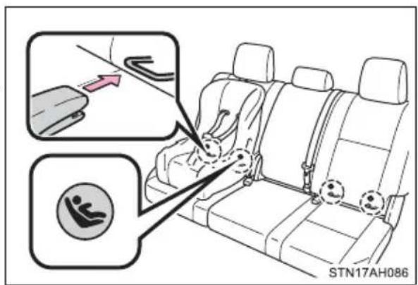
Seat belts equipped with a child restraint locking mechanism (ALR/ELR belts except driver's seat belt) ( P.36)
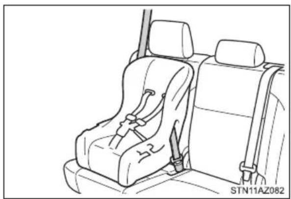
natural_image
Line drawing of a car backseat with seatbelt and rear seats (no text or symbols)Anchor bracket (for top tether strap)
An anchor bracket is provided on each rear seat.
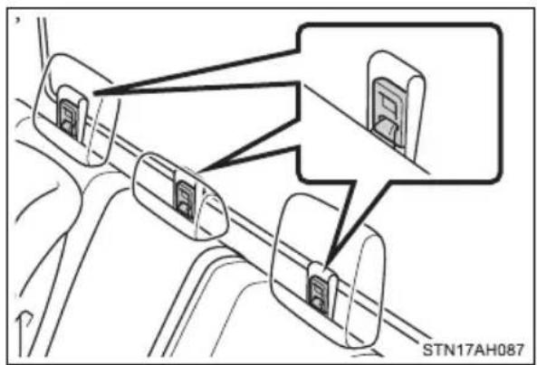
▶ CrewMax models
Child restraint LATCH anchors
LATCH anchors are provided for the outer rear seats.
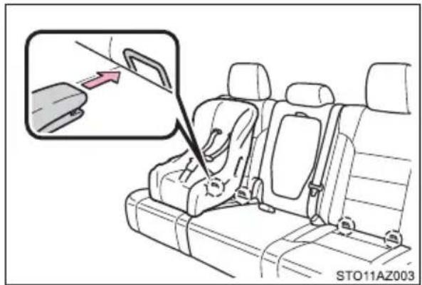
Seat belts equipped with a child restraint locking mechanism (ALR/ELR belts except driver's seat belt) ( P. 36)
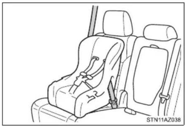
natural_image
Line drawing of a car seat assembly with rear seats and seatbelt (no text or symbols)Anchor bracket (for top tether strap)
An anchor bracket is provided on each rear seat.
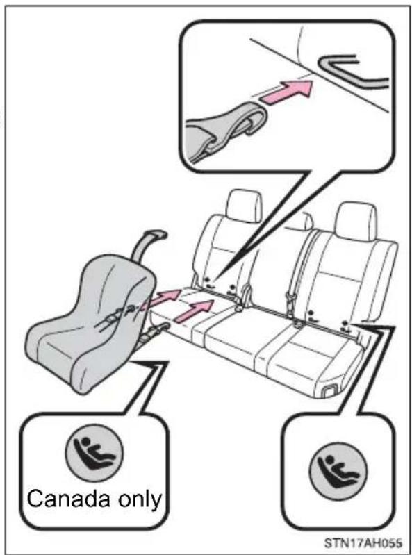
When installing in the rear outboard seats (Double Cab models)
▶ With flexible lower attachments
1 Widen the gap between the seat cushion and seatback slightly.
2 Latch the hooks of the lower attachments onto the LATCH anchors. If the child restraint has a top tether strap, the top tether strap should be latched onto the top tether strap anchor.
For owners in Canada:
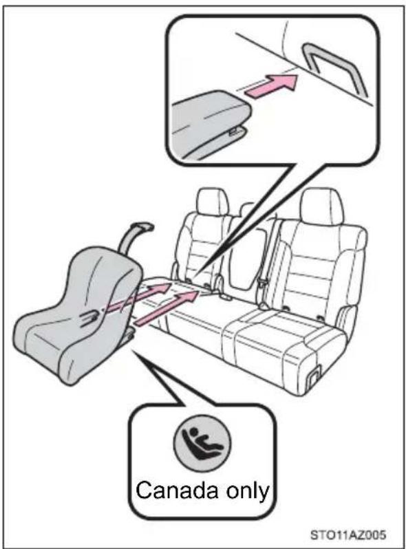
The symbol on a child restraint system indicates the presence of a lower connector system.
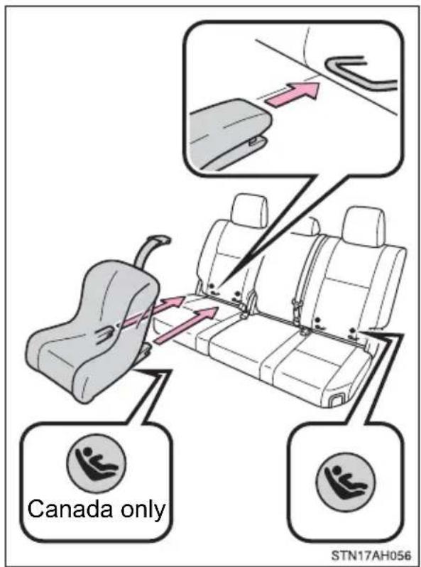
▶ With rigid lower attachments
1 Widen the gap between the seat cushion and seatback slightly.
2 Latch the buckles onto the LATCH anchors. If the child restraint has a top tether strap, the top tether strap should be latched onto the top tether strap anchor.
For owners in Canada:
The symbol on a child restraint system indicates the presence of a lower connector system.
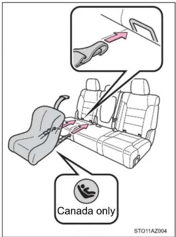
When installing in the rear outboard seats (CrewMax models)
▶ With flexible lower attachments
1 Widen the gap between the seat cushion and seatback slightly.
2 Latch the hooks of the lower attachments onto the LATCH anchors. If the child restraint has a top tether strap, the top tether strap should be latched onto the top tether strap anchor.
For owners in Canada:
The symbol on a child restraint system indicates the presence of a lower connector system.
▶ With rigid lower attachments
1 Widen the gap between the seat cushion and seatback slightly.
2 Latch the buckles onto the LATCH anchors. If the child restraint has a top tether strap, the top tether strap should be latched onto the top tether strap anchor.
For owners in Canada:
The symbol on a child restraint system indicates the presence of a lower connector system.
Installing child restraints using a seat belt (child restraint lock function belt)
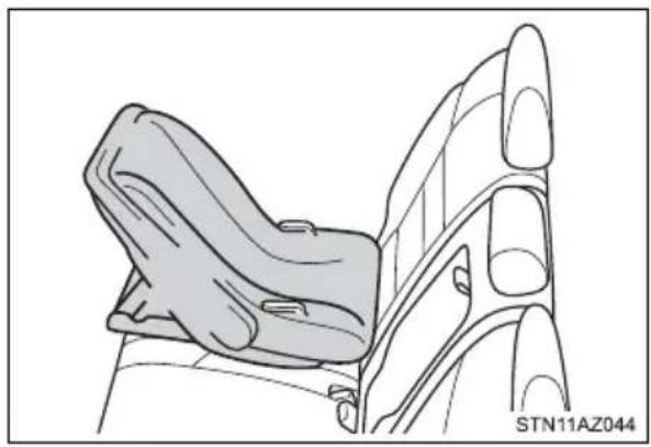
■ Rear-facing — Infant seat/convertible seat
1 Place the child restraint system on the seat facing the rear of the vehicle.
natural_image
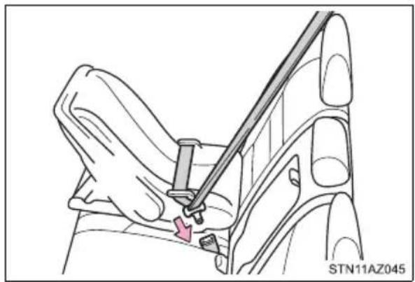
Line drawing of a car seat assembly with no text or symbols2 Run the seat belt through the child restraint system and insert the plate into the buckle. Make sure that the belt is not twisted.
natural_image
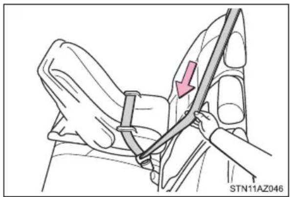
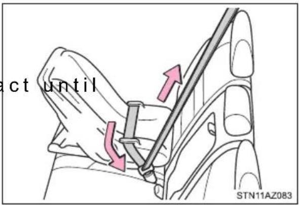
Diagram of a car seatbelt buckle being adjusted for a cable, showing no text or symbols3 Fully extend the shoulder belt and allow it to retract to put it in lock mode. In lock mode, the belt cannot be extended.
natural_image
Diagram of a car seatbelt being adjusted for a seatbelt, showing a hand adjusting the belt (no text or symbols present)4 While pushing the child restraint system down into the rear seat, allow the shoulder belt to retra the child restraint system is securely in place.
After the shoulder belt has retracted to a point where there is no slack in the belt, pull the belt to check that it cannot be extended.
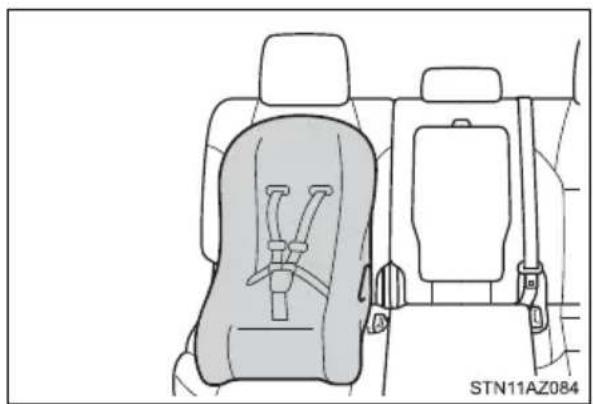
■ Forward-facing — Convertible seat
1 Place the child restraint system on the seat facing the front of the vehicle.
natural_image
Interior view of a car showing seatbelt and rear seats with no visible text or symbols2 Run the seat belt through the child restraint system and insert the plate into the buckle. Make sure that the belt is not twisted.
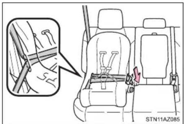
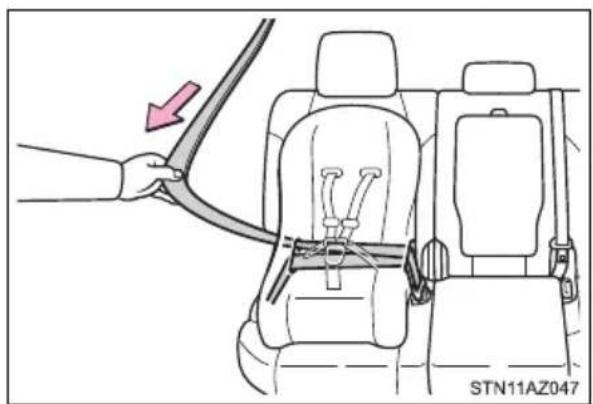
3 Fully extend the shoulder belt and allow it to retract to put it in lock mode. In lock mode, the belt cannot be extended.
natural_image
Diagram showing a hand adjusting a car seatbelt with a red arrow indicating the cable (no text or symbols present)4 While pushing the child restraint system into the rear seat, allow the shoulder belt to retract until the child restraint system is securely in place.
After the shoulder belt has retracted to a point where there is no slack in the belt, pull the belt to check that it cannot be extended.
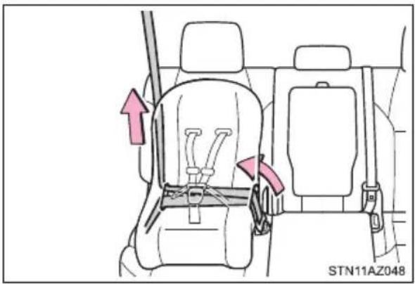
5 If the child restraint has a top tether strap, the top tether strap should be latched onto the top tether strap anchor.
(→P. 70, 73)
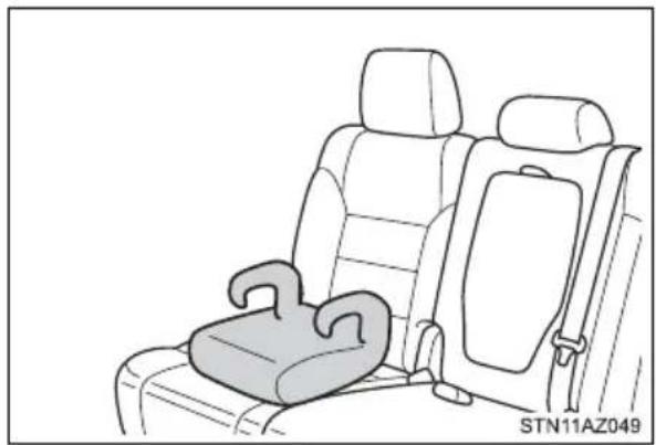
■ Booster seat
1 Place the child restraint system on the seat facing the front of the vehicle.
natural_image
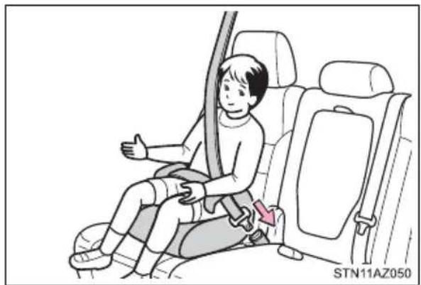
Line drawing of a car seat with rear seats and seatbelt, no text or symbols present2 Sit the child in the child restraint system. Fit the seat belt to the child restraint system according to the manufacturer's instructions and insert the plate into the buckle. Make sure that the belt is not twisted.
natural_image
Illustration of a child sitting in a car seat with a belt buckle, no text or symbols presentCheck that the shoulder belt is correctly positioned over the child's shoulder and that the lap belt is as low as possible. (→P. 34)
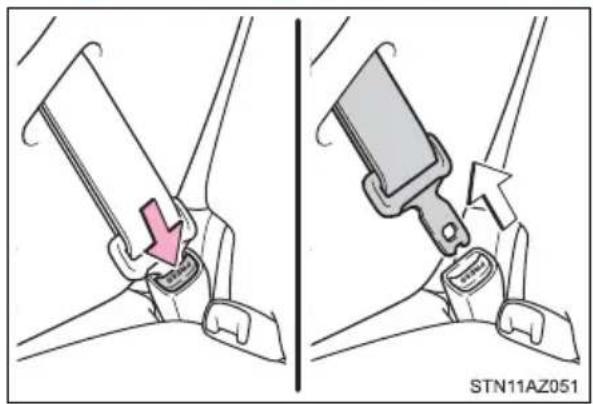
Removing a child restraint installed with a seat belt
Push the buckle release button and fully retract the seat belt.
natural_image
Illustration of a car seatbelt buckle being adjusted for a keyway, showing two states (no text or symbols present)Child restraint systems with a top tether strap (Double Cab models)
■Right rear seat or center rear seat
1 Secure the child restraint system using a seat belt or the lower anchors.
2 Remove the head restraints of right and center rear seats. (→P. 158)
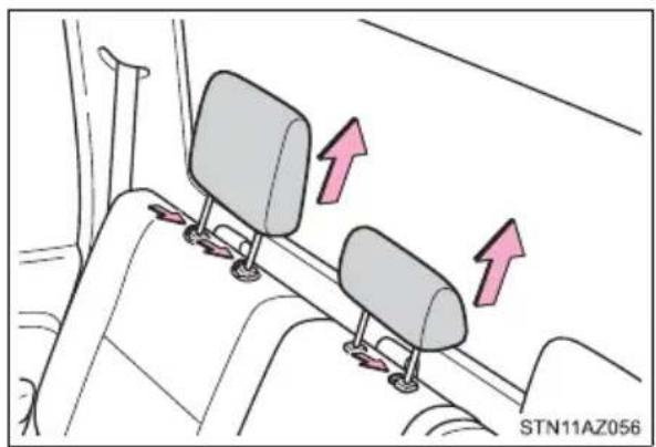
natural_image
Diagram showing two car seats mounted on a vehicle side, with two arrows indicating upward motion (no text or symbols present)3 Pull up the straps of right and center seats.
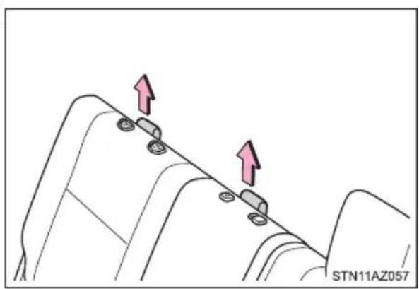
natural_image
Diagram showing two mechanical components with upward arrows, no text or symbols present4 Route the top tether strap through the anchor strap router as shown in the illustration.
Make sure the top tether strap is not twisted.
① Anchor strap router
▶ Right rear seat ▶ Center rear seat
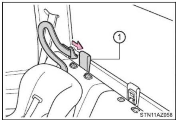
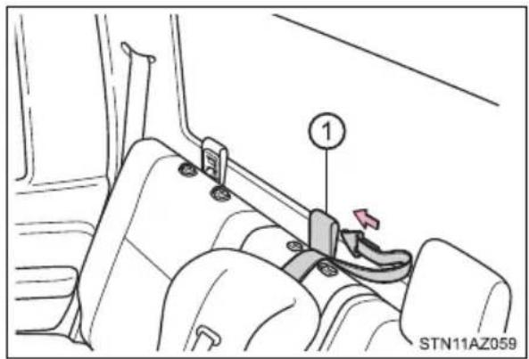
5 Latch the hook onto the anchor strap ring and tighten the top tether strap.
Make sure the top tether strap is securely latched.
① Anchor strap ring
▶ Right rear seat ▶ Center rear seat
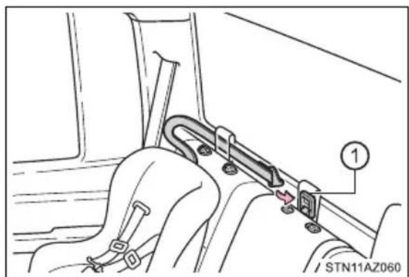
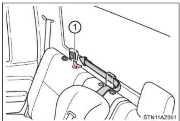
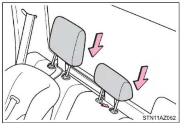
6 Replace the head restraints of right and center rear seats. (→P. 159)
natural_image
Diagram of a car steering wheel with two seats and directional arrows indicating motion (no text or symbols)■ Left rear seat
1 Secure the child restraint system using a seat belt or the lower anchors.
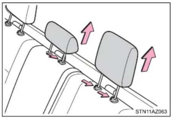
2 Remove the head restraints of center and left rear seats.
(→P. 158)
natural_image
Diagram showing two car seats mounted on a vehicle track with directional arrows indicating movement (no text or symbols)3 Pull up the straps of center and left seats.
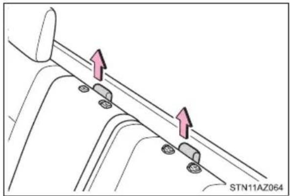
4 Route the top tether strap through the anchor strap router as shown in the illustration.
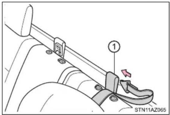
Make sure the top tether strap is not twisted.
① Anchor strap router
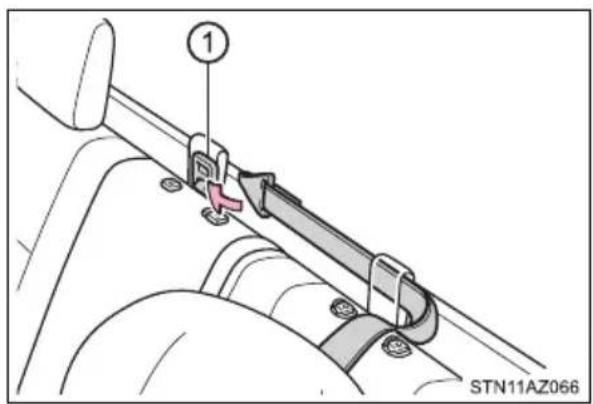
5 Latch the hook onto the anchor strap ring and tighten the top tether strap.
Make sure the top tether strap is securely latched.
① Anchor strap ring
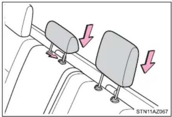
6 Replace the head restraints of center and left seats. (→P. 159)
natural_image
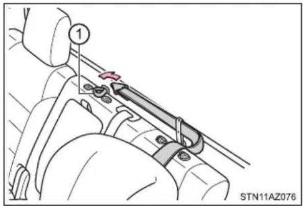
Diagram showing two car seats mounted on a vehicle, with arrows indicating downward motion (no text or symbols present)Child restraint systems with a top tether strap (CrewMax models)
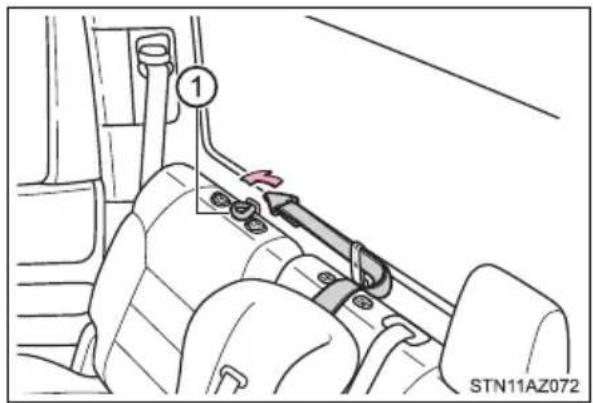
■Right rear seat or center rear seat
1 Secure the child restraint system using a seat belt or the lower anchors.
2 Remove the head restraints of the right and center rear seats. (→P. 158)
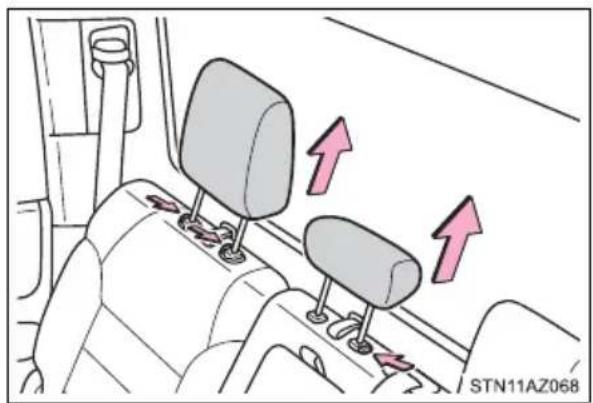
natural_image
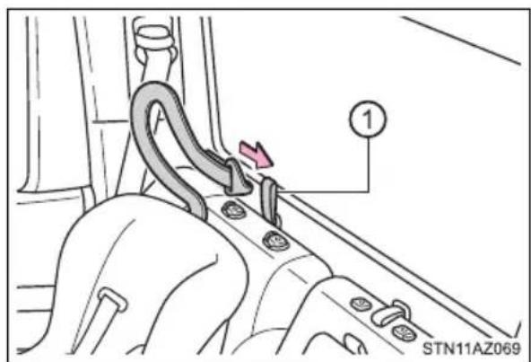
Interior view of a car showing seatbelt and dashboard with directional arrows (no text or symbols)3 Route the top tether strap through the anchor strap belt as shown in the illustration.
Make sure the top tether strap is not twisted.
① Anchor strap belt
▶ Right rear seat ▶ Center rear seat
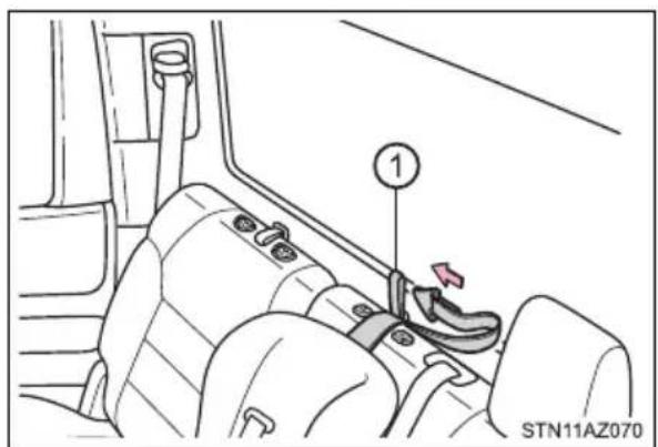
4 Latch the hook onto the anchor strap belt and tighten the top tether strap.
Make sure the top tether strap is securely latched.
① Anchor strap belt
▶ Right rear seat ▶ Center rear seat
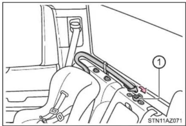
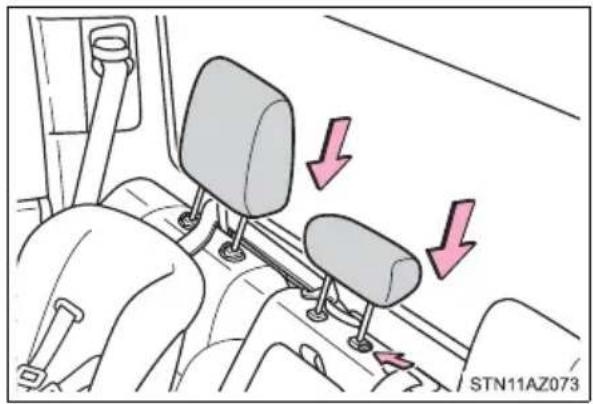
5 Replace the head restraints of right and center rear seats. (→P. 159)
natural_image
Diagram of car gear shift lever mechanism with two directional arrows indicating movement (no text or symbols)■Left seat
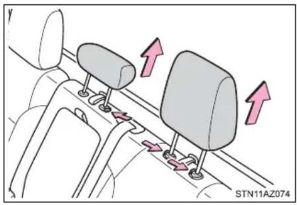
1 Secure the child restraint system using a seat belt or the lower anchors.
2 Remove the head restraints of the center and left rear seats. (→P. 158)
natural_image
Diagram of car backrests with directional arrows indicating movement or force (no text or symbols)3 Route the top tether strap through the anchor strap belt as shown in the illustration.
Make sure the top tether strap is not twisted.
① Anchor strap belt
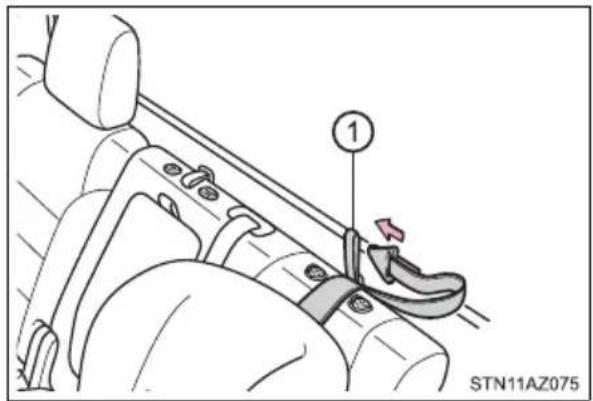
4 Latch the hook onto the anchor strap belt and tighten the top tether strap.
Make sure the top tether strap is securely latched.
① Anchor strap belt
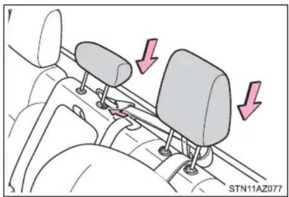
5 Replace the head restraints of center and left rear seats. (→P. 159)
■Laws and regulations pertaining to anchorages
The LATCH system conforms to FMVSS225 or CMVSS210.2.
Child restraint systems conforming to FMVSS213 or CMVSS213 specifications can be used.
This vehicle is designed to conform to the SAE J1819.

WARNING
■When installing a booster seat
To prevent the belt from going into ALR lock mode, do not fully extend the shoulder belt. ALR mode causes the belt to tighten only. This could cause injury or discomfort to the child. (→P. 36)
■When installing a child restraint system
Follow the directions given in the child restraint system installation manual and fix the child restraint system securely in place.
If the child restraint system is not correctly fixed in place, the child or other passengers may be seriously injured or even killed in the event of a sudden braking or an accident.
- If the driver's seat interferes with the child restraint system and prevents it from being attached correctly, attach the child restraint system to the right-hand rear seat.
- Adjust the front passenger seat so that it does not interfere with the child restraint system.
- Only put a forward-facing child restraint system on the front seat when unavoidable. When installing a forward-facing child restraint system on the front passenger seat, move the seat as far back as possible even if the "AIR BAG OFF" indicator light is illuminated. Failure to do so may result in death or serious injury if the airbags deploy (inflate).
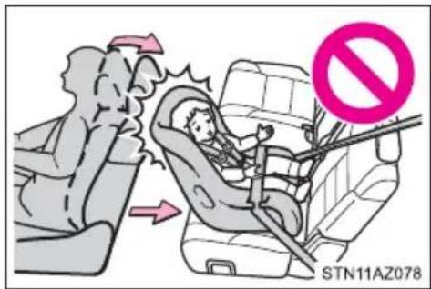
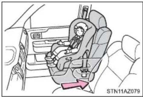
natural_image
Illustration of a child seated in a car seat, with no visible text or symbols on the diagram itself.
WARNING
■When installing a child restraint system
- When a booster seat is installed, always ensure that the shoulder belt is positioned across the center of the child's shoulder. The belt should be kept away from the child's neck, but not so that it could fall off the child's shoulder. Failure to do so may result in death or serious injury in the event of an accident or a sudden braking.
- Ensure that the belt and plate are securely locked and the seat belt is not twisted.
● Shake the child restraint system left and right, and forward and backward to ensure that it has been securely installed. - Follow all installation instructions provided by the child restraint system manufacturer.
- When securing some types of child restraint systems in rear seats, it may not be possible to properly use the seat belts in positions next to the child restraint without interfering with it or affecting seat belt effectiveness. Be sure your seat belt fits snugly across your shoulder and low on your hips. If it does not, or if it interferes with the child restraint, move to a different position. Failure to do so may result in death or serious injury. If the seat is adjusted, reconfirm the security of the child restraint system.
■ Do not use a seat belt extender
If a seat belt extender is used when installing a child restraint system, the seat belt will not securely hold the child restraint system, which could cause death or serious injury to the child or other passengers in the event of a sudden braking, sudden swerving or an accident.
■To correctly attach a child restraint system to the anchors
When using the LATCH anchors, be sure that there are no foreign objects around the anchors and that the seat belt is not caught behind the child restraint system. Make sure the child restraint system is securely attached, or it may cause death or serious injury to the child or other passengers in the event of a sudden braking or an accident.
Exhaust gas precautions
Harmful substance to the human body is included in exhaust gases if inhale.

WARNING
Exhaust gases include harmful carbon monoxide (CO), which is colorless and odorless. Observe the following precautions.
Failure to do so may cause exhaust gases to enter the vehicle and may lead to an accident caused by light-headedness, or may lead to death or a serious health hazard.
■ Important points while driving
●Double Cab and CrewMax models: Keep the back window closed.
● Double Cab and CrewMax models: If you smell exhaust gases in the vehicle even when the back window is closed, open the windows and have the vehicle inspected at your Toyota dealer as soon as possible.
Toyota does not recommend occupying the rear cargo area when it is fitted with a slide-in camper, camper shell or other type cover while the engine is running. This caution applies to both driving and stopped or parked situations with the engine running. Particular care should be taken to prevent exhaust gases from entering camper bodies, trailers or other enclosures on or around your vehicle. If exhaust fumes are detected, open all windows and thoroughly ventilate the area.
When parking
- If the vehicle is in a poorly ventilated area or a closed area, such as a garage, stop the engine.
- Do not leave the vehicle with the engine on for a long time. If such a situation cannot be avoided, park the vehicle in an open space and ensure that exhaust fumes do not enter the vehicle interior.
- Do not leave the engine running in an area with snow build-up, or where it is snowing. If snowbanks build up around the vehicle while the engine is running, exhaust gases may collect and enter the vehicle.
Exhaust pipe
The exhaust system needs to be checked periodically. If there is a hole or crack caused by corrosion, damage to a joint or abnormal exhaust noise, be sure to have the vehicle inspected and repaired by your Toyota dealer.
Safety Connect\*
Safety Connect is a subscription-based telematics service that uses Global Positioning System (GPS) data and embedded cellular technology to provide safety and security features to subscribers. Safety Connect is supported by Toyota's designated response center, which operates 24 hours per day, 7 days per week.
Safety Connect service is available by subscription on select, telematics hardware-equipped vehicles.
By using the Safety Connect service, you are agreeing to be bound by the Telematics Subscription Service Agreement and its Terms and Conditions, as in effect and amended from time to time, a current copy of which is available at Toyota.com in the United States, Toyotapr.com in Puerto Rico and Toyota.ca in Canada. All use of the Safety Connect service is subject to such then-applicable Terms and Conditions.
■System components
① Microphone
② LED light indicators
③ “SOS” button
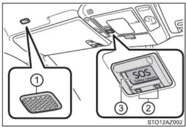
Services
Subscribers have the following Safety Connect services available:
●Automatic Collision Notification
Helps drivers receive necessary response from emergency service providers. ( P. 82)
* : U.S. Patent No. 7,508,298 B2
●Stolen Vehicle Location
Helps drivers in the event of vehicle theft. ( P. 82)
●Emergency Assistance Button ("SOS")
Connects drivers to response-center support. (→P. 82)
●Enhanced Roadside Assistance
Provides drivers various on-road assistance. ( P. 83)
Subscription
After you have signed the Telematics Subscription Service Agreement and are enrolled, you can begin receiving services. A variety of subscription terms are available for purchase. Contact your Toyota dealer, call the following appropriate Customer Experience Center or push the “SOS” button in your vehicle for further subscription details.
• The United States
1-800-331-4331
- Canada
1-888-869-6828
- Puerto Rico
1-877-855-8377
■Safety Connect Services Information
- Phone calls using the vehicle's Bluetooth ^ technology will not be possible when Safety Connect is active and in use.
● Safety Connect is available beginning Fall 2009 on select Toyota models (in the contiguous United States only). Contact with the Safety Connect response center is dependent upon the telematics device being in operative condition, cellular connection availability, and GPS satellite signal reception, which can limit the ability to reach the response center or receive emergency service support. Enrollment and Telematics Subscription Service Agreement are required. A variety of subscription terms are available; charges vary by subscription term selected and location.
● Automatic Collision Notification, Emergency Assistance and Stolen Vehicle Location are available in the United States, including Hawaii and Alaska, Puerto Rico and Canada, and Enhanced Roadside Assistance are available in the United States, Puerto Rico and Canada.
● Automatic Collision Notification, Emergency Assistance, Stolen Vehicle and Enhanced Road Assistance are not available in the U.S. Virgin Islands. For vehicles first sold in the U.S. Virgin Islands, no Safety Connect services will function in or outside the U.S. Virgin Islands.
● Safety Connect services are not subject to section 255 of the Telecommunications Act and the device is not TTY compatible.
Languages
The Safety Connect response center will offer support in multiple languages. The Safety Connect system will offer voice prompts in English, Spanish, and French. Please indicate your language of choice when enrolling.
■When contacting the response center
You may be unable to contact the response center if the network is busy.
Safety Connect LED light Indicators
When the engine switch is turned to ON, the red indicator light comes on for 2 seconds then turns off. Afterward, the green indicator light comes on, indicating that the service is active.
The following indicator light patterns indicate specific system usage conditions:
●Green indicator light on = Active service
●Green indicator light flashing = Safety Connect call in process
●Red indicator light (except at vehicle start-up) = System malfunction (contact your Toyota dealer)
● No indicator light (off) = Safety Connect service not active
Safety Connect LED light Indicators
■Automatic Collision Notification
In case of either airbag deployment or severe rear-end collision, the system is designed to automatically call the response center. The responding agent receives the vehicle's location and attempts to speak with the vehicle occupants to assess the level of emergency. If the occupants are unable to communicate, the agent automatically treats the call as an emergency, contacts the nearest emergency services provider to describe the situation, and requests that assistance be sent to the location.
■Stolen Vehicle Location
If your vehicle is stolen, Safety Connect can work with local authorities to assist them in locating and recovering the vehicle. After filing a police report, call the Customer Experience Center at 1-800-331-4331 in the United States, 1-877-855-8377 in Puerto Rico or 1-888-869-6828 in Canada, and follow the prompts for Safety Connect to initiate this service.
In addition to assisting law enforcement with recovery of a stolen vehicle, Safety-Connect-equipped vehicle location data may, under certain circumstances, be shared with third parties to locate your vehicle. Further information is available at Toyota.com in the United States, Toyotapr.com in Puerto Rico and Toyota.ca in Canada.
Emergency Assistance Button ("SOS")
In the event of an emergency on the road, push the “SOS” button to reach the Safety Connect response center. The answering agent will determine your vehicle’s location, assess the emergency, and dispatch the necessary assistance required.
If you accidentally press the "SOS" button, tell the response-center agent that you are not experiencing an emergency.
■Enhanced Roadside Assistance
Enhanced Roadside Assistance adds GPS data to the already included warranty-based Toyota roadside service.
Subscribers can press the “SOS” button to reach a Safety Connect response-center agent, who can help with a wide range of needs, such as: towing, flat tire, fuel delivery, etc. For a description of the Enhanced Roadside Assistance services and their limitations, please see the Safety Connect Terms and Conditions, which are available at Toyota.com in the United States, Toyotapr.com in Puerto Rico and Toyota.ca in Canada.
Safety information for Safety Connect
Important! Read this information before using Safety Connect.
■Exposure to radio frequency signals
The Safety Connect system installed in your vehicle is a low-power radio transmitter and receiver. It receives and also sends out radio frequency (RF) signals.
In August 1996, the Federal Communications Commission (FCC) adopted RF exposure guidelines with safety levels for mobile wireless phones. Those guidelines are consistent with the safety standards previously set by the following U.S. and international standards bodies.
●ANSI (American National Standards Institute) C95.1 [1992]
●NCRP (National Council on Radiation Protection and Measurement) Report 86 [1986]
●ICNIRP (International Commission on Non-Ionizing Radiation Protection) [1996]
Those standards were based on comprehensive and periodic evaluations of the relevant scientific literature. Over 120 scientists, engineers, and physicians from universities, and government health agencies and industries reviewed the available body of research to develop the ANSI Standard (C95.1).
The design of Safety Connect complies with the FCC guidelines in addition to those standards.
■Certification for Safety Connect
FCC ID: JOYDA39
IC: 574B-DA39
FCC/IC WARNING:
Changes or modifications not expressly approved by the manufacture could void the user's authority to operate the equipment.
This device complies with Part 15 of the FCC Rules and Industry Canada license-exempt RSS standards. Operation is subject to the following two conditions:
(1) this device may not cause harmful interference, and
(2) this device must accept any interference, including interference that may cause undesired operation of the device.
This equipment complies with IC RSS-102 radiation exposure limits set forth for uncontrolled environment.
The antennas used for this transmitter must be installed to provide a separation distance of least 20cm from all persons.
FCC/IC AVERTISSEMENT:
Engine immobilizer system
The vehicle's keys have built-in transponder chips that prevent the engine from starting if a key has not been previously registered in the vehicle's on-board computer.
Never leave the keys inside the vehicle when you leave the vehicle.
This system is designed to help prevent vehicle theft but does not guarantee absolute security against all vehicle thefts.
Vehicles without a smart key sys- tem:
The indicator light flashes after the key has been removed from the engine switch to indicate that the system is operating.
The indicator light stops flashing after the registered key has been inserted into the engine switch to indicate that the system has been canceled.
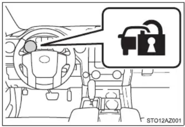
Vehicles with a smart key system:
The indicator light flashes after the engine switch has been turned off to indicate that the system is operating.
The indicator light stops flashing after the engine switch has been turned to ACC or ON to indicate that the system has been canceled.
System maintenance
The vehicle has a maintenance-free type engine immobilizer system.
■Conditions that may cause the system to malfunction
- If the grip portion of the key is in contact with a metallic object
- If the key is in close proximity to or touching a key to the security system (key with a built-in transponder chip) of another vehicle
■Certifications for the engine immobilizer system
For vehicles sold in the U.S.A.
FCC ID: MOZRI-42BTY
This device complies with Part 15 of the FCC Rules. Operation is subject to the following two conditions: (1) this device may not cause harmful interference, and (2) this device must accept any interference received, including interference that may cause undesired operation.
For vehicles sold in Canada
This device complied with RSS-210 of Industry Canada.
Operation is subject to the following two conditions: (1) this device may not cause interference, and (2) this device must accept any interference, including interference that may cause undesired operation of the device.
For vehicles sold in New Caledonia

Address: 3-260 Toyota, Oguchi-cho, Niwa-gun, Aichi 480-0195, Japan
| Hereby, TOKAI RIKA CO., LTD. declares that the radio equipment type RI-42BTY is in compliance with Directive 2014/53/EU.The full text of the EU declaration of conformity is available at the following internet address:http://www.tokai-rika.co.jp/pcFrequency band: 134.2 kHzMaximum radio-frequency power: 55.5dBμA/m @10m |
| TOKAI RIKA CO., LTD. vakuuttaa, että radidaitetyppi RI-42BTY on direktiivin 2014/53/EU mukainen.EU-vaatimustenmukaisuusvakuutuksen täysimittainen teksti on saatavilla seuraavassa internetosoitteessa:http://www.tokai-rika.co.jp/pcRadiotaajuus: 134.2 kHzsuurin mahdollinen lähetysteho: 55.5dBμA/m @10m |
| Hierbij verklaar ik, TOKAI RIKA CO., LTD., dat het type radioapparatuur RI-42BTY conform is met Richtlijn 2014/53/EU.De volledige tekst van de EU-conformiteitsverklaring kan worden geraadpleegd op het volgende internetadres:http://www.tokai-rika.co.jp/pcFrequentieband: 134.2 kHzMaximaal radiofrequentievermogen: 55.5dBμA/m @10m |
| Le soussigné, TOKAI RIKA CO., LTD., déclare que l'équipement radioélectrique du type RI-42BTY est conforme à la directive 2014/53/UE.Le texte complet de la déclaration UE de conformité est disponible à l'adresse internet suivante:http://www.tokai-rika.co.jp/pcBande de fréquences: 134.2 kHzPuissance de radiofréquence maximale: 55.5dBμA/m @10m |
| Härmed försäkrar TOKAI RIKA CO., LTD. att denna typ av radioutrustning RI-42BTY överensstämmer med direktiv 2014/53/EU.Den fullständiga texten till EU-försäkran om överensstämmelse finns på följande webbadress:http://www.tokai-rika.co.jp/pcFrekvensband: 134.2 kHzMaximal radiofrekvenseffekt: 55.5dBμA/m @10m |
| Hermed erklærer TOKAI RIKA CO., LTD., at radioudstyrstypen RI-42BTY er i overensstemmelse med direktiv 2014/53/EU.EU-overensstemmelseserklæringens fulde tekst kan findes på følgende internetadresse:http://www.tokai-rika.co.jp/pcFrekvensbånd: 134.2 kHzMaksimal radiofrekvenseffekt: 55.5dBμA/m @10m |
| Hiermit erklärt TOKAI RIKA CO., LTD., dass der Funkanlagentyp RI-42BTY der Richtlinie 2014/53/EU entspricht.Der vollständige Text der EU-Konformitätserklärung ist unter der folgenden Internetadresse verfügbar:http://www.tokai-rika.co.jp/pcFrequenzband: 134.2 kHzAbgestrahlte maximale Sendeleistung: 55.5dBμA/m @10m |
| Με την παρούσα ο/η TOKAI RIKA CO. LTD., δηλώνει ότι οραδιοεξοπλισμός RI-42BTY πληροί την οδηγία 2014/53/EE.To πλήρες κείμενο της δήλωσης συμμόρφωσης ΕΕ διατίθεται στηνακόλουθη ιστοσελίδα στο διαδίκτυο:http://www.tokai-rika.co.jp/pcZώνη συχνοτήτων: 134.2 kHzΜέγιστη ισχύς ραδιοσυχνότητας: 55.5dBμA/m @10m |
| Il fabbricante, TOKAI RIKA CO., LTD., dichiara che il tipo diapparecchiatura radio RI-42BTY è conforme alla direttiva2014/53/UE.Il testo completo della dichiarazione di conformità UE è disponibile al seguente indirizzo Internet:http://www.tokai-rika.co.jp/pcBanda di frequenza: 134.2 kHzPotenza massima radiofrequenza: 55.5dBμA/m @10m |
| Por la presente, TOKAI RIKA CO., LTD. declara que el tipo de equiporadioeléctrico RI-42BTY es conforme con la Directiva 2014/53/UE.El texto completo de la declaración UE de conformidad estádisponible en la dirección Internet siguiente:http://www.tokai-rika.co.jp/pcBanda de frecuencia: 134.2 kHzPotencia máxima de radiofrecuencia: 55.5dBμA/m @10m |
| O(a) abaixo assinado(a) TOKAI RIKA CO., LTD. declara que opresente tipo de equipamento de rádio RI-42BTY está emconformidade com a Diretiva 2014/53/UE.O texto integral da declaração de conformidade está disponível noseguinte endereço de Internet:http://www.tokai-rika.co.jp/pcBanda de frequência: 134.2 kHzPotência máxima de radiofrequências: 55.5dBμA/m @10m |
B'dan, TOKAI RIKA CO., LTD., niddikjara li dan it-tip ta' taghmir tar-radju RI-42BTY huwa konformi mad-Direttiva 2014/53/UE.
It-test kollu tad-dikjarazzjoni ta' konformità tal-UE huwa disponibbli f'dan l-indirizz tal-Internet li gej: http://www.tokai-rika.co.jp/pc
■Certifications for the immobilizer system
Changes or modifications not expressly approved by the party responsible for compliance could void the user's authority to operate the equipment.

NOTICE
■To ensure the system operates correctly
Do not modify or remove the system. If modified or removed, the proper operation of the system cannot be guaranteed.
Alarm\*
The alarm
The alarm uses light and sound to give an alert when an intrusion is detected.
The alarm is triggered in the following situations when the alarm is set:
● A locked door is unlocked or opened in any way other than using a key or wireless remote control. (The doors will lock again automatically.)
●The hood is opened.
● Vehicles with the glass breakage sensor: The side windows are tapped or broken.
Setting the alarm system
Close the doors and hood, and lock all the doors. The system will be set automatically after 30 seconds.
The indicator light changes from being on to flashing when the system is set.
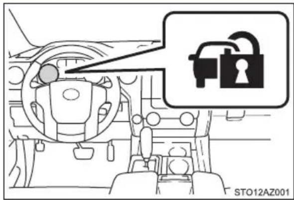
Deactivating or stopping the alarm
Do one of the following to deactivate or stop the alarms:
- Unlock the doors.
● Turn the engine switch to the ACC or ON, or start the engine. (The alarm will be deactivated or stopped after a few seconds.)
System maintenance
The vehicle has a maintenance-free type alarm system.
Items to check before locking the vehicle
To prevent unexpected triggering of the alarm and vehicle theft, make sure of the following:
●Nobody is in the vehicle.
● The windows and moon roof (if equipped) are closed before the alarm is set.
●No valuables or other personal items are left in the vehicle.
■Triggering of the alarm
The alarm may be triggered in the following situations:
(Stopping the alarm deactivates the alarm system.)
● A person inside the vehicle opens a door or hood.
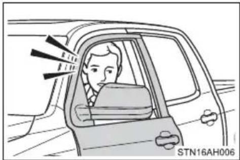
●The battery is recharged or replaced when the vehicle is locked.
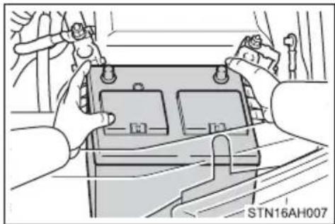
natural_image
Illustration of hands installing or adjusting a battery cover with tools (no text or symbols visible)■Alarm-operated door lock
In the following cases, depending on the situation, the door may automatically lock to prevent improper entry into the vehicle:
- When a person remaining in the vehicle locks the door and the alarm is activated.
● While the alarm is activated, a person remaining in the vehicle unlocks the door. - When recharging or replacing the battery.

NOTICE
■To ensure the system operates correctly
Do not modify or remove the system. If modified or removed, the proper operation of the system cannot be guaranteed.
Instrument cluster
2
2. Instrument cluster
Warning lights and
indicators 100
Gauges and meters ..... 105
Multi-information display ... 110
Fuel consumption
information 117
Warning lights and indicators
The warning lights and indicators on the instrument cluster and center panel inform the driver of the status of the vehicle's various systems.
For the purpose of explanation, the following illustration displays all warning lights and indicators illuminated.
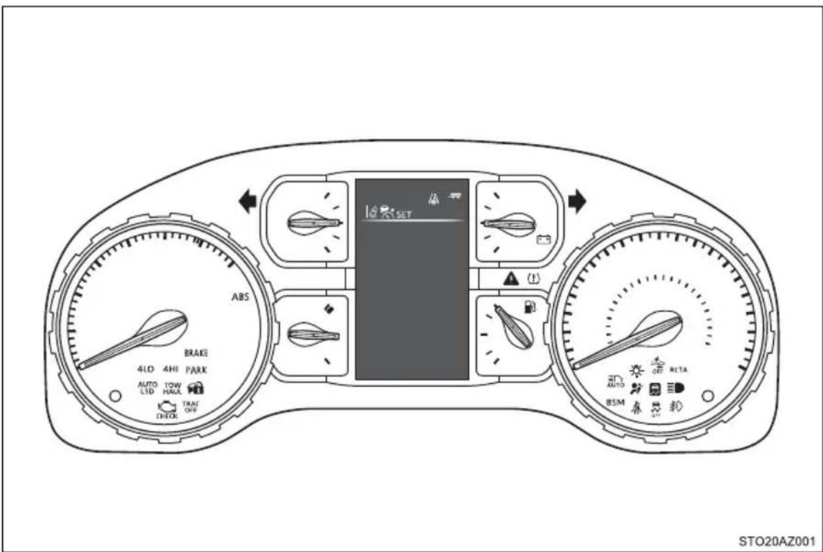
Warning lights
Warning lights inform the driver of malfunctions in the indicated vehicle's systems.
*1 (U.S.A.) (U.S.A.) | Brake system warning light (→P. 485) |  | Seat belt reminder light (→P. 486) |
*1 (Canada) (Canada) | Brake system warning light (→P. 485) |  | Master warning light (→P. 486) |
*1 | Charging system warning light (→P. 485) |  (U.S.A.) (U.S.A.) | Parking brake warning light (→P. 486) |
*1 (U.S.A.) (U.S.A.) | Malfunction indicator lamp (→P. 485) |  (Canada) (Canada) | Parking brake warning light (→P. 486) |
*1 (Canada) (Canada) | Malfunction indicator lamp (→P. 485) |  | Tire pressure warning light (→P. 487) |
*1 | SRS warning light (→P. 485) |  | Slip indicator (→P. 487) |
*1 (U.S.A.) (U.S.A.) | ABS warning light (→P. 486) |  | PCS warning light (→P. 488) |
*1 (Canada) (Canada) | ABS warning light (→P. 486) |  (Yellow) (Yellow) | LDA indicator (→P. 488) |
*1 | Low fuel level warning light (→P. 486) |  | High engine coolant temperature warning light (→P. 484) |
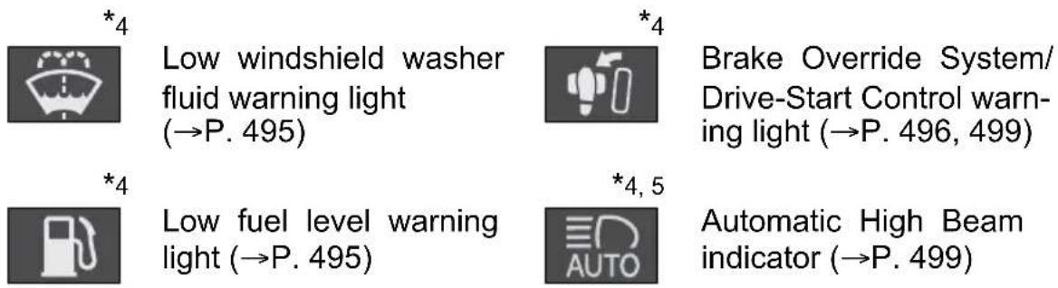
*1: These lights turn on when the engine switch is turned to ON to indicate that a system check is being performed. They will turn off after the engine is started, or after a few seconds. There may be a malfunction in a system if the lights do not come on, or if the lights do not turn off. Have the vehicle inspected by your Toyota dealer for details.
*2: The light comes on to indicate a malfunction.
*3: The light flashes to indicate a malfunction.
*4: The light illuminates on the multi-information display.
*5: If equipped
Indicators
The indicators inform the driver of the operating state of the vehicle's various systems.
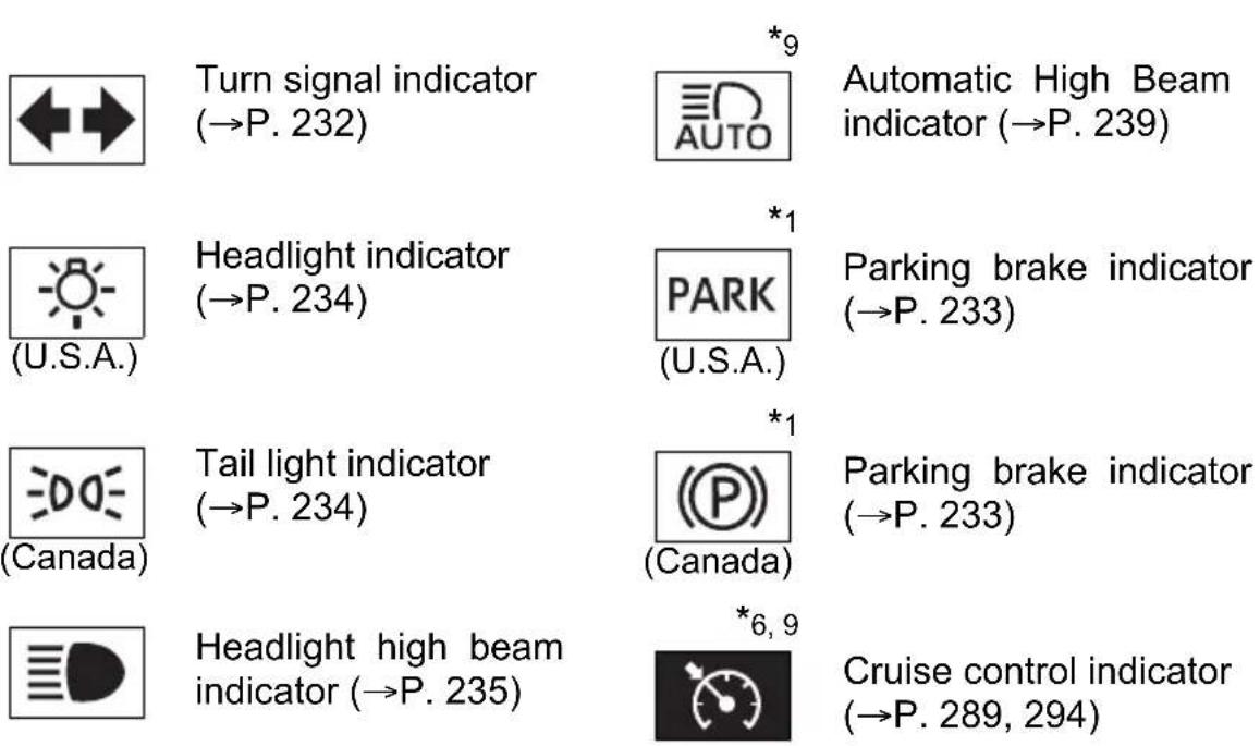
*6 | Cruise control “SET” indicator (→P. 289, 294) | *3, 4, 9 | BSM outside rear view mirror indicator(→P. 305) |
*6, 9 (Green) (Green) | LDA indicator (→P. 276) | *1 | “TRAC OFF” indicator(→P. 321) |
 | Front fog light indicator(→P. 244) | *9 | “RCTA” indicator(→P. 305) |
*1, 5 | “AIR BAG ON” and “AIR BAG OFF” indicators (→P. 53) |  | Security indicator(→P. 85, 95)“AUTO LSD” indicator(→P. 318, 321) |
*6, 9 | Dynamic radar cruise control indicator(→P. 280) | *1, 8, 9 | PCS warning light(→P. 264) |
*1, 2 | Slip indicator(→P. 321) |  (4WD models) (4WD models) | “4HI” indicator (→P. 315) |
*1 | VSC off indicator(→P. 318, 321) |  (4WD models) (4WD models) | “4LO” indicator (→P. 315) |
 | “TOW HAUL” indicator(→P. 228) | *6 (Green) (Green) | Trailer connection indicator (→P. 327) |
*9 | “BSM” indicator(→P. 305) | *6, 7 | Low outside temperature indicator |
*1: These lights turn on when the engine switch is turned to ON to indicate that a system check is being performed. They will turn off after the engine is started, or after a few seconds. There may be a malfunction in a system if the lights do not come on, or if the lights do not turn off. Have the vehicle inspected by your Toyota dealer for details.
^*2 : The light flashes to indicate that the system is operating.
*3: In order to confirm operation, the BSM outside rear view mirror indicators illuminate in the following situations:
- When the engine switch is turned to ON, the BSM function is enabled on the screen of the multi-information display.
- When the BSM function is enabled on the screen of the multi-information display, the engine switch is turned to ON.
If the system is functioning correctly, the BSM outside rear view mirror indicators will turn off after a few seconds.
If the BSM outside rear view mirror indicators do not illuminate or do not turn off, there may be a malfunction with the system.
If this occurs, have the vehicle inspected by your Toyota dealer.
*4: The light illuminates on the outside rear view mirrors.
*5: The light illuminates on the center panel.
*6: The light illuminates on the multi-information display.
*7: When the outside temperature is approximately 37^ (3°C) or lower, the indicator will flash for 10 times, then comes on.
*8: The light comes on when the system is turned off.
*9: If equipped

WARNING
If a safety system warning light does not come on
Should a safety system light such as the ABS and SRS warning light not come on when you start the engine, this could mean that these systems are not available to help protect you in an accident, which could result in death or serious injury. Have the vehicle inspected by your Toyota dealer immediately if this occurs.
Gauges and meters
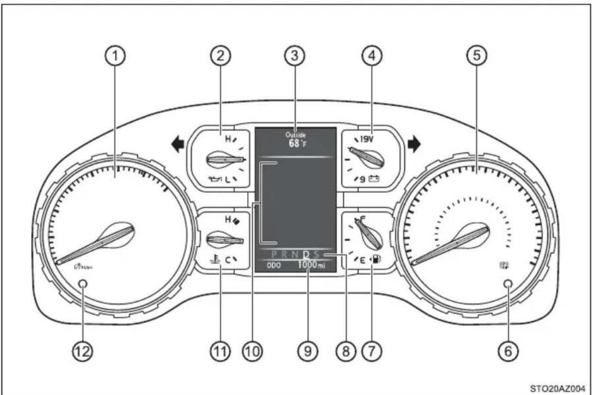
① Tachometer
Displays the engine speed in revolutions per minute
② Engine oil pressure gauge
Displays the engine oil pressure
③ Outside temperature display
Displays the outside temperature within the range of -40^ (-40°C) to 122^ (50°C). Low outside temperature indicator comes on when the ambient temperature is 37^ (3°C) or lower.
④ Voltmeter
Displays the charge state
⑤ Speedometer
Displays the vehicle speed
⑥ Odometer/Trip meter switching and trip meter resetting button
Switches between odometer and trip meter displays. Pushing and holding the button will reset the trip meter when the trip meter is being displayed.
⑦ Fuel gauge
Displays the quantity of fuel remaining in the tank.
⑧ Shift position and shift range display
Displays the selected shift position or selected shift range. (→P. 225)
⑨ Odometer and trip meter display
Displays the following items.
Odometer:
Displays the total distance the vehicle has been driven.
Trip meter:
Displays the distance the vehicle has been driven since the meter was last reset. Trip meters A and B can be used to record and display different distances independently.
⑩ Multi-information display
Presents the driver with a variety of driving-related data. (→P. 111)
Displays warning messages in case of a malfunction. (→P. 493)
⑪ Engine coolant temperature gauge
Displays the engine coolant temperature.
⑫ Instrument panel light control button
Changing the odometer/trip meter display
Pressing the button switches between odometer and trip meter.
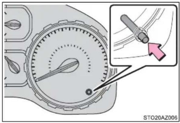
Odometer
Displays the total distance the vehicle has been driven.
■Trip meter A\*/trip meter B\*
Displays the distance the vehicle has been driven since the meter was last reset. Trip meters A and B can be used to record and display different distances independently.
*: Press and hold the display change button to reset.
Instrument panel light control
The brightness of the instrument panel lights can be adjusted.
Pressing the button will adjust brightness of the instrument panel light.
The brightness of the instrument panel lights can be adjusted by pressing the button.
Short press: 1 step change of brightness level.
Long press: continues change of brightness level until released.

■The multi-information display illuminate when
The engine switch is in ON.
■The brightness of the instrument panel lights
When the tail lights are turned on, the display's brightness will be reduced slightly unless the meter brightness level adjustment is set to the brightest setting.
■ Outside temperature display
- In the following situations, the correct outside temperature may not be displayed, or the display may take longer than normal to change.
- When stopped, or driving at low speeds (less than 12 mph [20 km/h])
- When the outside temperature has changed suddenly (at the entrance/exit of a garage, tunnel, etc.)
- When “--” or “E” is displayed, the system may be malfunctioning. Take your vehicle to your Toyota dealer.
Liquid crystal display
Small spots or light spots may appear on the display. This phenomenon is characteristic of liquid crystal displays, and there is no problem continuing to use the display.

WARNING
■The information display at low temperatures
Allow the interior of the vehicle to warm up before using the liquid crystal information display. At extremely low temperatures, the information display monitor may respond slowly, and display changes may be delayed. For example, there is a lag between the driver's shifting and the new gear number appearing on the display. This lag could cause the driver to downshift again, causing rapid and excessive engine braking and possibly an accident resulting in personal death or injury.

NOTICE
■To prevent damage to the engine and its components
- Do not let the indicator needle of the tachometer enter the red zone, which indicates the maximum engine speed.
The engine may be overheating if the engine coolant temperature gauge is in the red zone (H). In this case, immediately stop the vehicle in a safe place, and check the engine after it has cooled completely. (→P. 529)
Voltmeter
When the voltmeter indicates 19 V or higher or 9 V or lower while the engine is running, there may be a battery or charging system malfunction. Have the vehicle inspected at your Toyota dealer.
■Engine oil pressure gauge
When the value of the engine oil pressure gauge drops while the engine is running, stop the vehicle in a safe place immediately and check the amount of engine oil. ( P. 416)
When the oil pressure drops even though the engine oil amount has not decreased, or if the oil pressure does not increase when engine oil is added, contact your Toyota dealer, as there may be a problem with the lubrication system.
Multi-information display
Display contents
The multi-information display presents the driver with a variety of vehicle data.
●Menu icons
Displays the following information when an icon is selected. Some of the information may be displayed automatically depending on the situation.
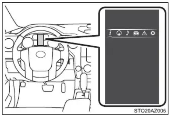

Drive information
Select to display various drive data. ( P. 111)

Navigation system-linked display*
Select to display the following navigation system-linked information.
- Route guidance
- Compass display (north-up display/heading-up display)

Audio system-linked display
Select to enable selection of an audio source or track on the meter using the meter control switches.
Vehicle information
Select to display the operational status of the following systems:
• LDA (Lane Departure Alert) * (→P. 272)
• Dynamic radar cruise control * (→P. 280)
• Tire inflation pressure (→P. 427)
- Trailer brake controller * (→P. 327)

Warning message display
Select to display warning messages and measures to be taken if a malfunction is detected. (→P. 493)

Settings display
Select to change the meter display settings. (→P. 112)
*: If equipped
■ Operating the meter control switches
① Select an item/change pages
② Press: Enters/Sets
Press and hold: Resets
③ Switch menu/Displays the top screen
④ Returns to the previous screen
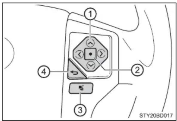
Drive information
● Total Average */Tank Average/Trip Average
Displays the average fuel consumption since the function was reset, the vehicle was refueled, or the engine was started, respectively
Use the displayed average fuel consumption as a reference.
●Range
Displays the estimated maximum distance that can be driven with the quantity of fuel remaining, the distance driven after the engine was started or the distance since the function was reset, respectively.
- This distance is computed based on your average fuel consumption. As a result, the actual distance that can be driven may differ from that displayed.
- When only a small amount of fuel is added to the tank, the display may not be updated.
When refueling, turn the engine switch off. If the vehicle is refueled without turning the engine switch off, the display may not be updated.
●Current
Displays the current rate of fuel consumption
●Average Speed\*/Trip Average Speed
Displays the average since engine was started or the average since the function was reset, respectively
●Total Time \*/Trip Time
Displays the engine was started or the elapsed time since the function was reset, respectively
●Trip distance
Displays the distance since the engine was started
●Digital speedometer
●Display off
A blank screen is displayed
\*: Resetting procedures:
- Select a function to be reset using the meter control switch and then press and hold the center button to reset.
- If there is more than one function that can be reset, check boxes will be displayed next to the functions.
Settings display
The settings of the following items can be changed, refer to P. 564.
For functions that can be enabled or disabled, the function switches between on and off each time is pressed.
●LDA (Lane Departure Alert) ^*1 ( P. 567)
- LDA Sensitivity
Select to set up the LDA (Lane Departure Alert) sensitivity. - Sway warning
Select to enable/disable the Sway warning function. - Sway warning sensitivity
Select to set up the sway warning sensitivity.
●PCS (Pre-Collision System) ^* ^1 ( P. 567)
- PCS
Select to enable/disable the PCS (Pre-Collision System) function. - Sensitivity
Select to set up the PCS (Pre-Collision System) sensitivity.
●BSM (Blind Spot Monitor) ^* 1 ( P. 567)
Select to enable/disable the Blind Spot Monitor function.
●RCTA (Rear Cross Traffic Alert) ^*1 ( P. 567)
Select to enable/disable the Rear Cross Traffic Alert function.
●Vehicle Settings
• BSM Brightness ^* 1 ( P. 567)
Select to set up the BSM (Blind Spot Monitor) outside rear view mirror indicators brightness.
• R C T A v*1b(→P.r567e)
Select to set up the RCTA (Rear Cross Traffic Alert) warning buzzer volume.
• TBC Trailer Type *1 (→P. 568)
Select to set up the trailer brake type.
- Maintenance reset *2 (→P. 407)
Select to reset the message after the required maintenance is performed.
●Meter setting
- Language
Select to change the language on the display.
- Units
Select to change the unit of measure for fuel consumption and temperature.
- Switch settings
You can register 1 screen as the top screen. To register, press and hold
while the desired screen is displayed.
There are also screens that cannot be setup as the Top Screen.
- Drive information 1 and 2
Select to select up to 2 items that will be displayed on a Drive information screen, up to 2 Drive information screens can be set.
- Pop-up display
Select to set the following pop-up displays, which may appear in some situations, on/off.
- Route guidance display of the navigation system-linked system (if equipped)
- Incoming call display of the hands-free phone system
- Instrument panel brightness adjustment display
- Accent color
Select to change the accent colors on the screen, such as the menu icon color.
- Default settings
Registered or changed meter settings will be deleted or returned to their default setting.
*1: If equipped
*2: For vehicles sold in the U.S.A.
Setting items
● “Vehicle Settings” and “Meter Settings” setting items are not selectable during driving and cannot be operated.
Also, the settings screen is temporarily canceled in the following situations.
- When a warning message appears.
- When the vehicle begins to move.
●Settings for functions not equipped to the vehicle are not displayed.
- When a function is turned off, the related settings for that function are not selectable.
■Pop-up display
In some situations, such as when a switch operation is performed, a pop-up display will be temporarily displayed on the multi-information display.
■When disconnecting and reconnecting battery terminals
The drive information will be reset.
■Trip summary display
When the engine switch is turned off, each of the following will be displayed on the multi-information display, and will clear after approximately 30 seconds.
- Distance traveled
●Average fuel consumption
●Driving range
■Tire inflation pressure
- It may take a few minutes to display the tire inflation pressure after the engine switch is turned to ON. It may also take a few minutes to display the tire inflation pressure after inflation pressure has been adjusted.
- “---” may be displayed if the tire position information cannot be determined due to unfavorable radio wave conditions.
● Tire inflation pressure changes with temperature. The displayed values may also be different from the values measured using a tire pressure gauge.
Liquid crystal display
Small spots or light spots may appear on the display. This phenomenon is characteristic of liquid crystal displays, and there is no problem continuing to use the display.

WARNING
■Caution for use while driving
- When operating the multi-information display while driving, pay extra attention to the safety of the area around the vehicle.
- Do not look continuously at the multi-information display while driving as you may fail to see pedestrians, objects on the road, etc. ahead of the vehicle.
■Cautions during setting up the display
As the engine needs to be running during setting up the display, ensure that the vehicle is parked in a place with adequate ventilation. In a closed area such as a garage, exhaust gases including harmful carbon monoxide (CO) may collect and enter the vehicle. This may lead to death or a serious health hazard.

NOTICE
During setting up the display
To prevent battery discharge, ensure that the engine is running while setting up the display features.
Fuel consumption information\*
The fuel consumption information can be displayed on Audio, Premium Audio and Audio Plus screen.
Display the trip information or past record screen
Audio
Press the "TRUCK" button.
▶ Premium Audio and Audio Plus
Press the "APPS" button, and then select "Eco" on the screen.
Fuel consumption
■Trip information
If the "Past Record" screen is displayed, select "Trip Information".
① Resetting the consumption data
② Average vehicle speed since the engine was started
③ Elapsed time since the engine was started
④ Fuel consumption in the past 15 minutes
⑤ Cruising range ( P.118)
⑥ Current fuel consumption
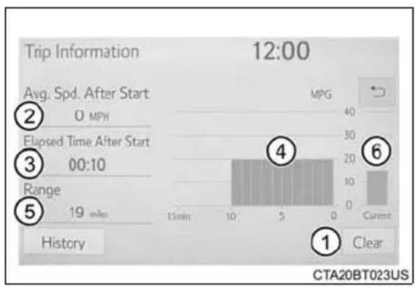
bar
| Metric | Value | | :--- | :--- | | Avg. Spd. After Start | 0 MPH | | Elapsed Time After Start | 00:10 | | Range | 19 miles | | History | | | MPG | 40 | | Current | 15 | CTA20BT023US 12:00Average fuel consumption for the past 15 minutes is divided by color into past averages and averages attained since the engine switch was last turned to ON. Use the displayed average fuel consumption as a reference.
These images are examples only.
Past record
If the "Trip Information" screen is displayed, select "Past Record".
① Resetting the past record data
② Best recorded fuel consumption
③ Average fuel consumption (if equipped)
④ Previous fuel consumption record
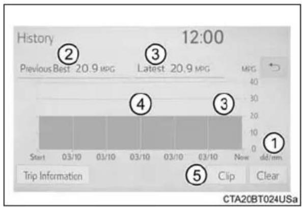
bar
History 12:00 | Point | Value (MPG) | | :--- | :--- | | ① | 1 | | ② | 2 | | ③ | 3 | | ④ | 4 | | ⑤ | 5 | CTA20BT024USA⑤ Update the average fuel consumption data
The average fuel consumption history is divided by color into past averages and the average fuel consumption since the last updated. Use the displayed average fuel consumption as a reference.
These images are examples only.
■ Resetting the data
The fuel consumption data can be deleted by selecting "Clear".
■ Updating the past record data
Update the average fuel consumption by selecting "Update" to measure the current fuel consumption again.
Cruising range
Displays the estimated maximum distance that can be driven with the quantity of fuel remaining.
This distance is computed based on your average fuel consumption. As a result, the actual distance that can be driven may differ from that displayed.
Operation of each component
3
3-1. Key information
Keys 120
3-2. Opening, closing and locking the doors
Side doors.... 127
Tailgate 133
Smart key system...... 138
3-3. Adjusting the seats
Front seats 147
Rear seats.... 150
Driving position memory (driver's seat) 152
Head restraints.... 157
3-4. Adjusting the steering wheel and mirrors
Steering wheel 161
Inside rear view mirror..... 164
Outside rear view mirrors.... 167
3-5. Opening, closing the windows and moon roof
Power windows 172
Back window 175
Power back window ..... 176
Moon roof.... 179
Keys
The keys
▶ Type A
① Keys
② Key number plate
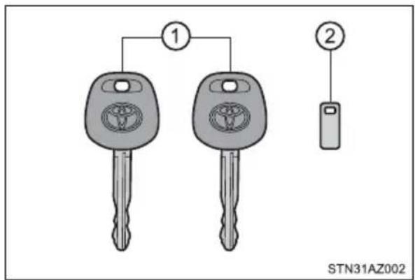
▶ Type B
① Keys
Operating the wireless remote control function
② Key number plate
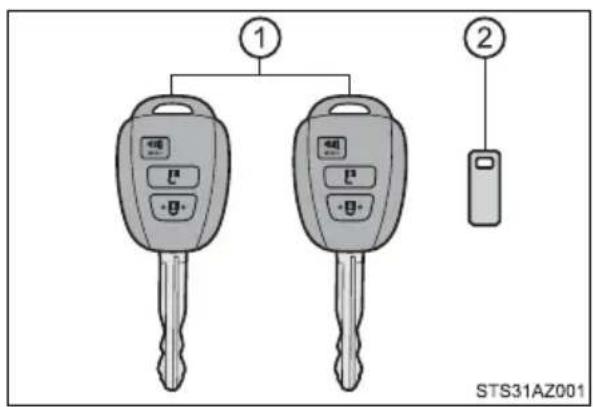
▶ Type C
① Electronic keys
- Operating the smart key system (→P. 138)
- Operating the wireless remote control function
② Key number plate
③ Key
④ Key number plate
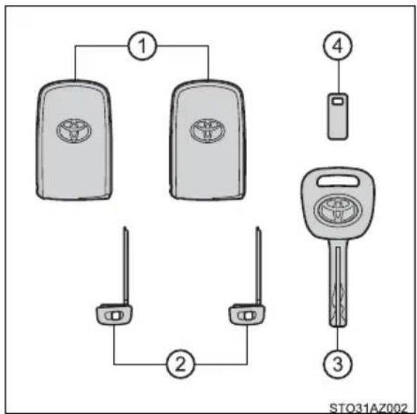
Wireless remote control (type B or type C)
▶ Type B
① Locks all the doors ( P. 127)
② Unlocks all the doors ( P. 127)
Pressing the button unlocks the driver's door. Pressing the button again within 3 seconds unlocks the other doors.
③ Sounds the alarm (press and hold) (→P. 122)
▶ Type C
① Locks all the doors ( P. 127)
② Unlocks all the doors ( P. 127)
Pressing the button unlocks the driver's door. Pressing the button again within 3 seconds unlocks the other doors.
③ Sounds the alarm (press and hold) ( P. 122)
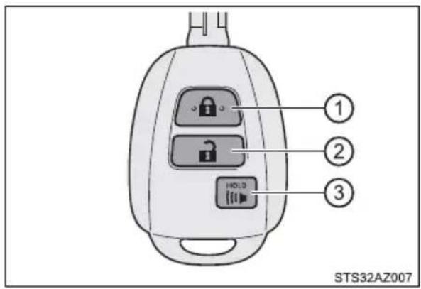
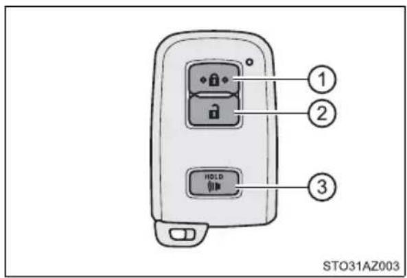
Using the mechanical key (type C)
To take out the mechanical key, push the release button and take the key out.
The mechanical key can only be inserted in one direction, as the key only has grooves on one side.
If the key cannot be inserted in a lock cylinder, turn it over and reattempt to insert it.
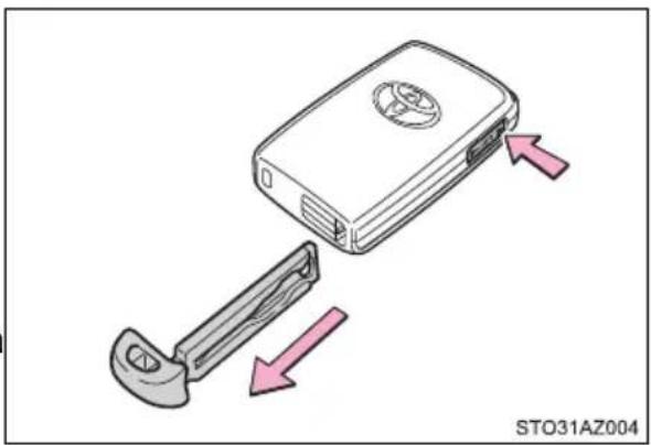
natural_image
Diagram of a device with an open lid and two arrows indicating movement or assembly (no text or symbols present)After using the mechanical key, store it in the electronic key. Carry the mechanical key together with the electronic key. If the electronic key battery is depleted or the entry function does not operate properly, you will need the mechanical key. (→P. 523)
■Panic mode (type B or type C)
When \$HOLD pressed for longer than about 1 second, an alarm will sound intermittently and the vehicle lights will flash to deter any person from trying to break into or damage your vehicle.
To stop the alarm, press any button on the key (with a wireless remote control function) or electronic key.
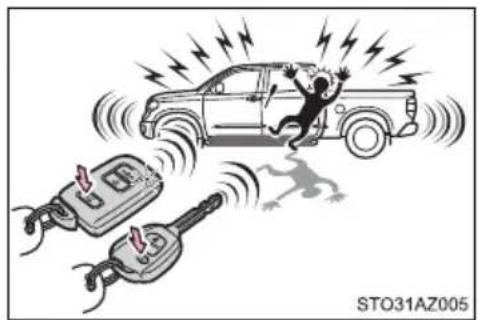
natural_image
Illustration of a person falling into the noise of an electric vehicle and a plug, with no visible text or symbols.- When required to leave the vehicle's key with a parking attendant (type C)
Lock the glove box as circumstances demand. (→P. 362)
Remove the mechanical key for your own use and provide the attendant with the electronic key only.
If you lose your keys
▶ Type A and B
New genuine key can be made by your Toyota dealer using the other key and the key number stamped on your key number plate.
Keep the plate in a safe place such as your wallet, not in the vehicle.
▶ Type C
New genuine key can be made by your Toyota dealer.
The following are necessary when making new keys.
Mechanical key:
The key number for the mechanical key stamped on the number plate and the other key.
Key:
The key number for key stamped on the key number plate.
Keep the plates in a safe place such as your wallet, not in the vehicle.
There are key number plates for the mechanical key and key respectively. When storing them, keep them in a safe place in a manner to distinguish one from the other (such as markings, etc.).
■When riding in an aircraft (type B or type C)
When bringing an wireless remote control function onto an aircraft, make sure you do not press any button on the key while inside the aircraft cabin. If you are carrying the key in your bag, etc., ensure that the buttons are not likely to be pressed accidentally. Pressing a button may cause the key to emit radio waves that could interfere with the operation of the aircraft.
■Conditions affecting operation (type B or type C)
▶ Type B
The wireless remote control function may not operate normally in the following situations.
● Near a TV tower, radio station, electric power plant, airport or other facility that generates strong radio waves
- When carrying a portable radio, cellular phone or other wireless communication device
- When multiple wireless keys are in the vicinity
- When the wireless key has come into contact with, or is covered by a metallic object
- When a wireless key (that emits radio waves) is being used nearby
- When the wireless key has been left near an electrical appliance such as a personal computer
▶ Type C
→P. 142
■Key battery depletion (type B or type C)
▶ Type B
If the wireless remote control function does not operate, the battery may be depleted. Replace the battery when necessary. ( P. 451)
▶ Type C
●The standard battery life is 1 to 2 years.
- If the battery becomes low, an alarm will sound in the cabin when the engine stops. (→P. 503)
As the electronic key always receives radio waves, the battery will become depleted even if the electronic key is not used. The following symptoms indicate that the electronic key battery may be depleted. Replace the battery when necessary. (→P. 451)
- The smart key system or the wireless remote control does not operate.
- The detection area becomes smaller.
- The LED indicator on the key surface does not turn on.
● To avoid serious deterioration, do not leave the electronic key within 1 m (3 ft.) of the following electrical appliances that produce a magnetic field:
• TVs
- Personal computers
- Cellular phones, cordless phones and battery chargers
- Recharging cellular phones or cordless phones
- Table lamps
- Induction cookers
■Replacing the battery (type B or type C)
→P. 451
■ Confirmation of the registered key number
The number of keys already registered to the vehicle can be confirmed. Ask your Toyota dealer for details.
■ Customization (type B or type C)
Settings (e.g. wireless remote control system) can be changed.
■Certification for wireless remote control (type B)
For vehicles sold in the U.S.A.
FCC ID: GQ4-52T
FCC ID: GQ4-49R
NOTE:
This device complies with part 15 of the FCC Rules. Operation is subject to the following two conditions: (1) This device may not cause harmful interference, and (2) this device must accept any interference received, including interference that may cause undesired operation.
FCC WARNING:
Changes or modifications not expressly approved by the party responsible for compliance could void the user's authority to operate the equipment.
The FCC ID/IC Certification number is affixed inside the equipment. You can find the ID/number when replacing the battery.
For vehicles sold in Canada
NOTE:
This device complies with Industry Canada's license-exempt RSSs. Operation is subject to the following two conditions: (1) This device may not cause interference; and (2) This device must accept any interference, including interference that may cause undesired operation of the device.
The FCC ID/IC Certification number is affixed inside the equipment. You can find the ID/number when replacing the battery.
NOTE:
■Certification for wireless remote control (type C)
→P. 145

NOTICE
■To prevent key damage
- Do not drop the keys, subject them to strong shocks or bend them.
- Do not expose the keys to high temperatures for long periods of time.
- Do not get the keys wet or wash them in an ultrasonic washer, etc.
- Do not attach metallic or magnetic materials to the keys or place the keys close to such materials.
- Do not disassemble the keys.
- Do not attach a sticker or anything else to the surface of the key.
- Do not place the keys near objects that produce magnetic fields, such as TVs, audio systems and induction cookers, or medical electrical equipment, such as low-frequency therapy equipment.
- Carrying the electronic key on your person (type C)
Carry the electronic key 3.9 in. (10 cm) or more away from electric appliances that are turned on. Radio waves emitted from electric appliances within 3.9 in. (10 cm) of the electronic key may interfere with the key, causing the key to not function properly.
In case of a smart key system malfunction or other key-related problems (type C)
Take your vehicle with all the electronic keys provided with your vehicle to your Toyota dealer.
■When an electronic key is lost (type C)
If the electronic key remains lost, the risk of vehicle theft increases significantly. Visit your Toyota dealer immediately with all remaining electronic keys that was provided with your vehicle.
Side doors
Unlocking and locking the doors from the outside
Key
▶ Vehicles without a smart key system
① Locks all the doors
② Unlocks all the doors
Turning the key unlocks the driver's door. Turning the key again unlocks the other doors.
Vehicles with moon roof:
③ Closes the moon roof (turn and hold)
④ Opens the moon roof (turn and hold)
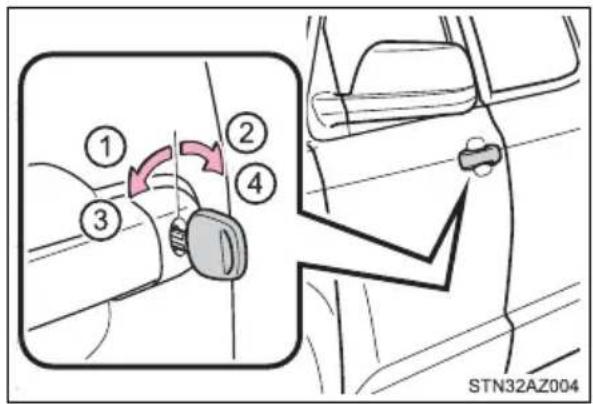
▶ Vehicles with a smart key system
The doors can also be locked and unlocked with the mechanical key. ( P. 523)
◆ Wireless remote control (if equipped)
▶ Vehicles without a smart key system
▶ Vehicles with a smart key system
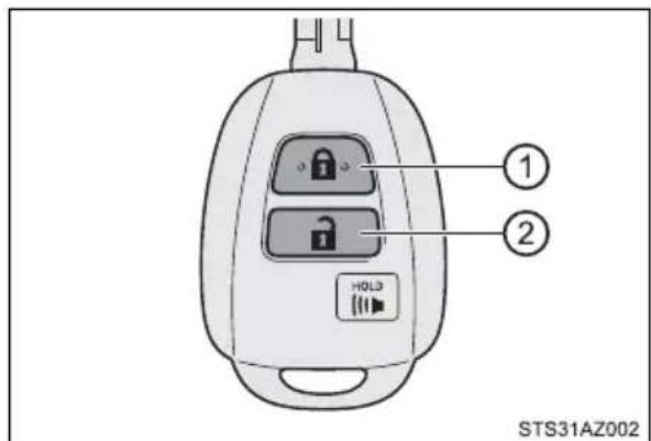
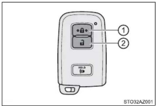
① Locks all the doors
Check that the door is securely locked.
② Unlocks all the doors
Pressing the button unlocks the driver's door. Pressing the button again within 3 seconds unlocks the other doors.
Smart key system (if equipped)
Carry the electronic key to enable this function.
① Grip the driver's door handle to unlock the door. Grip the passenger's door handle to unlock all the doors.
Make sure to touch the sensor on the back of the handle.
The doors cannot be unlocked for 3 seconds after the doors are locked.
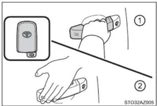
② Touch the lock sensor (the indentation on the side of the door handle) to lock the doors.
Check that the door is securely locked.
Operation signals (vehicles with a wireless remote control or smart key system)
A buzzer sounds and the emergency flashers flash to indicate that the doors have been locked/unlocked. (Locked: once; Unlocked: twice)
■ When the door cannot be locked by the lock sensor on the surface of the door handle (vehicles with a smart key system)
When the door cannot be locked even if the lock sensor on the surface of the door handle is touched by a finger, touch the lock sensor with the palm.
When gloves are being worn, remove the gloves.
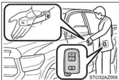
■ Door lock buzzer (vehicles with a wireless remote control or smart key system)
If an attempt to lock the doors is made when a door is not fully closed, buzzer sounds continuously for 5 seconds. Fully close the door to stop the buzzer, and lock the vehicle once more.
■ Security feature (vehicles with a wireless remote control or smart key system)
If a door is not opened within approximately 60 seconds after the vehicle is unlocked, the security feature automatically locks the vehicle again.
■Alarm (if equipped)
Using the wireless remote control to lock the doors will set the alarm system. (→P. 95)
If the smart key system or the wireless remote control does not operate properly (if equipped)
Use the mechanical key to lock and unlock the doors. (→P. 523)
Replace the battery with a new one if it is depleted. (→P. 451)
Unlocking and locking the doors from the inside
■Door lock switch
① Locks all the doors
② Unlocks all the doors
Driver's door lock switch
▶ Passenger's door lock switch
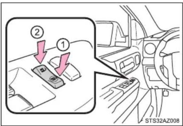
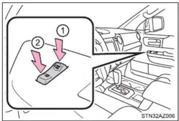
■Inside lock buttons
① Locks the door
② Unlocks the door
The front doors can be opened by pulling the inside handle even if the lock buttons are in the lock position.
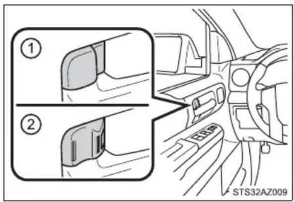
Locking the front doors from the outside without a key
▶ Vehicles without a smart key system
1 Move the inside lock button to the lock position.
2 Close the door.
Vehicles with power door lock system:
The door cannot be locked if either of the front doors is open and the key is in the engine switch.
▶ Vehicles with a smart key system
The door cannot be locked if the engine switch is in ACC or ON, or the electronic key is left inside the vehicle.
The key may not be detected correctly and the door may be locked.
Rear door child-protector lock
The door cannot be opened from inside the vehicle when the lock is set.
① Unlock
② Lock
These locks can be set to prevent children from opening the rear doors. Push down on each rear door switch to lock both rear doors.
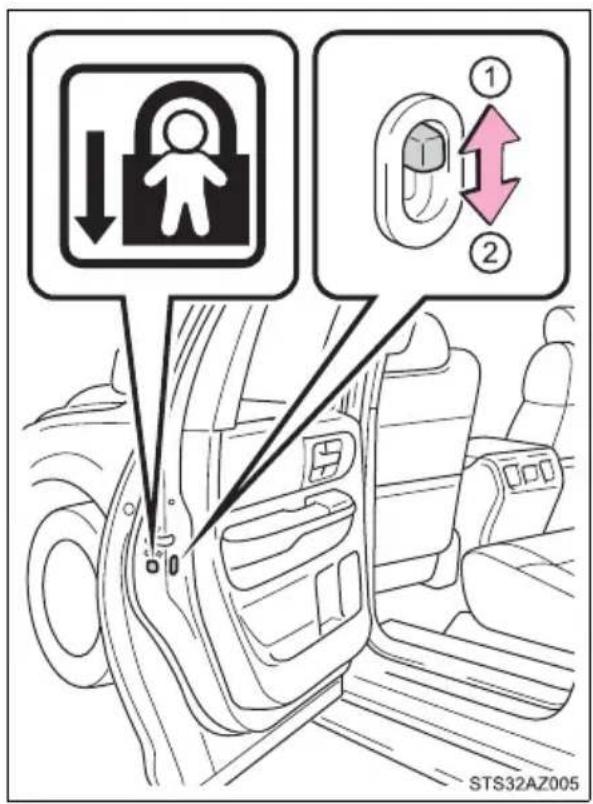
Automatic door locking and unlocking systems
The following functions can be set or canceled:
| Function Operation | |
| Shift position linked door locking function | Shifting the shift lever out of P locks all the doors. |
| Shift position linked door unlocking function | Shifting the shift lever to P unlocks all the doors. |
| Speed linked door locking function | All the doors are locked when the vehicle speed is approximately 12 mph (20 km/h) or higher. |
| Driver's door linked door unlocking function | All the doors are unlocked when the driver's door is opened within 10 seconds after turning the engine switch to OFF. |
■ Customization that can be configured at Toyota dealer
Settings (e.g. unlocking function using a key) can be changed.
Observe the following precautions while driving the vehicle.
Failure to do so may result in a door opening and an occupant throwing out of the vehicle, resulting in death or serious injury.
● Ensure that all doors are properly closed and locked.
- Do not pull the inside handle of the doors while driving.
Be especially careful for the front doors, as the doors may be opened even if the inside lock buttons are in locked position.
● Double Cab and CrewMax models: Set the rear door child-protector locks when children are seated in the rear seats.
Tailgate
The tailgate can be opened using the tailgate handle. The tailgate can be locked/unlocked using a key.
Locking/unlocking the tailgate
① Unlock the tailgate
② Lock the tailgate
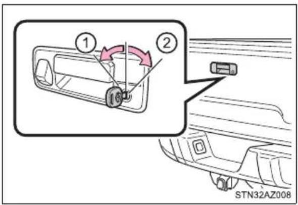
Opening/closing the tailgate
① Pull the handle
② Open the tailgate slowly
The support cables will hold the tailgate horizontal.
③ Lift and close the tailgate After closing the tailgate, try pulling it toward you to make sure it is securely locked.
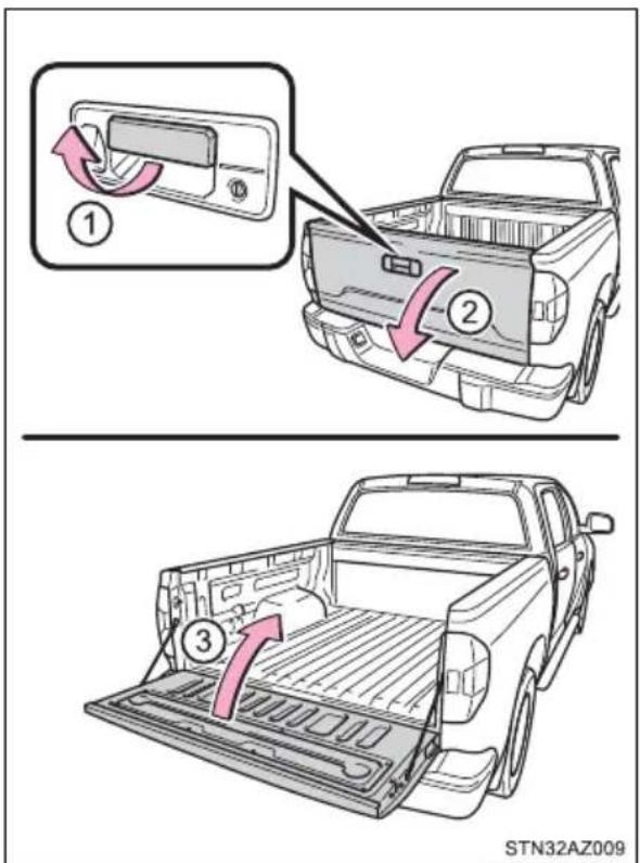
Removing the tailgate
■Before removing the tailgate
These connector covers are used when removing the tailgate, to prevent the back-up camera wire harness connectors from being contaminated.
Ⓐ Connector cover (Gray)
(B) Connector cover (White)
Store the connector covers in the glove box in a plastic bag when not using.
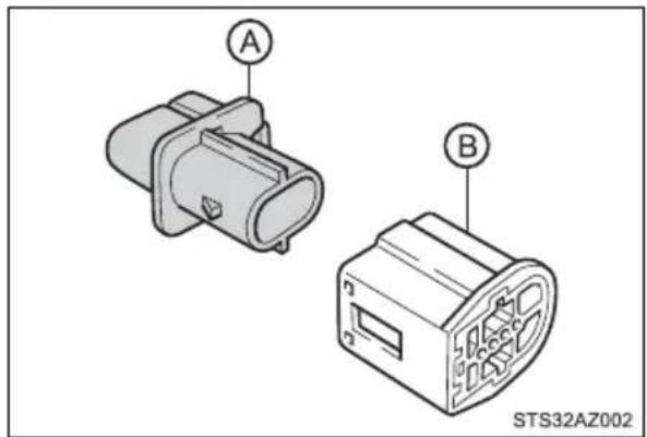
natural_image
Technical illustration of two electronic component enclosures labeled A and B, no text or symbols present1 To disconnect the wire harness connectors ( and ), ② depress small plastic tab on connector and pull apart from connector ②
① Tailgate wire harness connector (White)
② Frame wire harness connector (Gray)
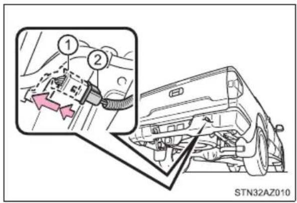
2 Attach the connector cover (White) to the frame wire harness connector (Gray).
B Connector cover (White)
② Frame wire harness connector (Gray)
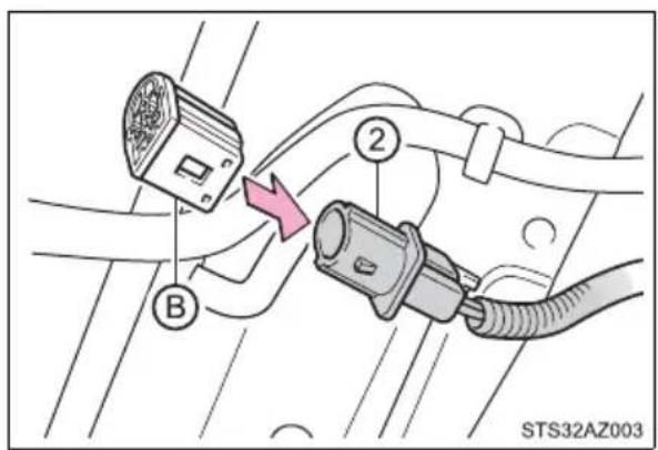
3 Open the tailgate.
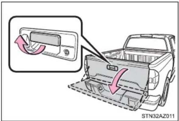
4 Pull out the plastic wire protector located in the vehicle bed by pressing the tabs and pulling the protector.
© Plastic wire protector
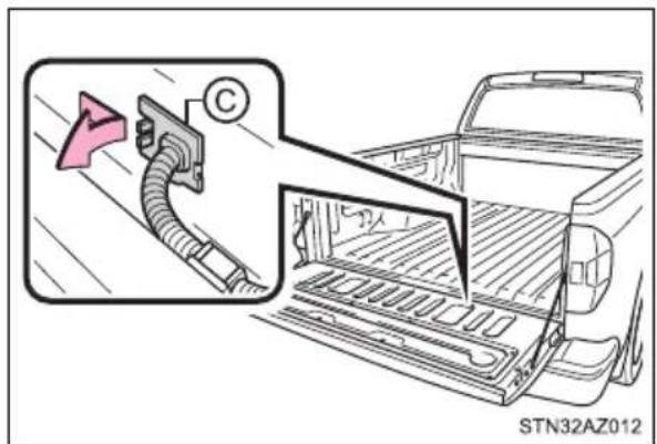
5 Pull out the wire harness from the vehicle bed.
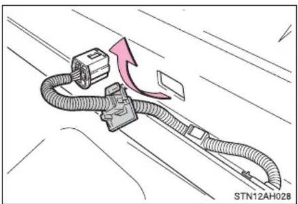
natural_image
Diagram of a cable connector with a pink arrow indicating direction, no text or symbols present6 Attach the connector cover (Gray) to the tailgate wire harness connector (White).
① Tailgate wire harness connector (White)
Ⓐ Connector cover (Gray)
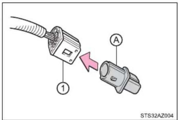
■Removing the tailgate
1 Open the tailgate to the angle where you can release the brackets on the support cables from the lugs on both sides. Lift the support cable bracket up and slide it off.
To unhook the support cable bracket, keep pulling up the clip on the bracket and unhook the bracket.
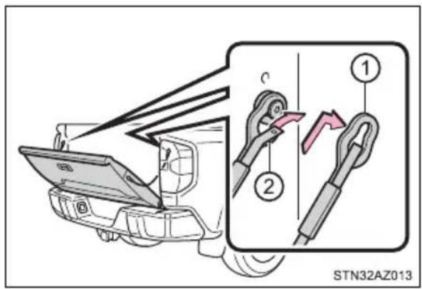
① Support cable bracket
② Clip
2 Tilt the tailgate to about 45^ from vertical and pull up the right side of the tailgate to unhook the right side.
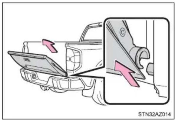
3 Tilt the tailgate up to 15^ .
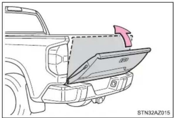
natural_image
Diagram of a vehicle's rear bumper showing the door panel and side panel, with no text or symbols present.4 Slide the tailgate a little to the right to unhook the left side. To attach the tailgate, follow the removal procedure in reverse order.
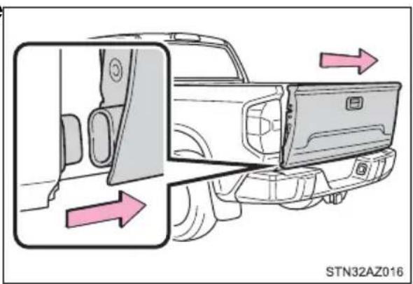
Rear step bumper
For rear end protection and easier step-up loading.
To get on the rear step bumper, use the shaded area in the illustration.
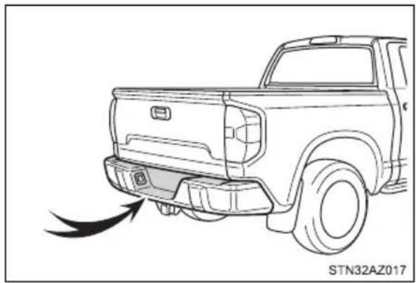
natural_image
Line drawing of a pickup truck showing front bumper and exhaust plume (no text or symbols)
WARNING
■Before removing the tailgate
Disconnect the wire harness between the back-up camera and the vehicle. Failure to do so may result in serious personal injury or damage to the vehicle components.
■Caution while driving
Observe the following precautions. Failure to do so may result in death or serious personal injury.
- Do not drive with the tailgate open.
- Do not allow others to get on the rear step bumper.

NOTICE
■To prevent damage to the tailgate wire harness
Do not pull out all of the tailgate wire harness before opening the tailgate.
■To prevent damage to the camera lens
Store the removed tailgate with the back-up camera lens facing upward.
■After closing the tailgate
Try pulling it toward you to make sure it is securely locked.
■To prevent damage to the rear step bumper
Do not allow more than one person to get on the rear step bumper at a time.
Smart key system\*
The following operations can be performed simply by carrying the electronic key on your person, for example in your pocket. The driver should always carry the electronic key.
- Locks and unlocks the doors (→P. 128)
- Starts the engine (→P. 219)
Antenna location
① Antennas outside the cabin
② Antennas inside the cabin
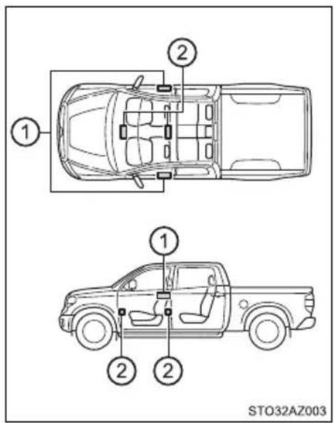
■ Effective range (areas within which the electronic key is detected)

When locking or unlocking the doors
The system can be operated when the electronic key is within about 2.3 ft. (0.7 m) of the driver's door handle. (Only the door detecting the key can be operated.)
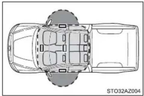
natural_image
Top-down schematic of a car showing front, rear, and side views with no text or symbols
When starting the engine or changing engine switch modes
The system can be operated when the electronic key is inside the vehicle.
■Alarms and warning indicators
A combination of exterior and interior alarms as well as warning messages shown on the multi-information display are used to prevent theft of the vehicle and accidents resulting from erroneous operation. Take appropriate measures in response to any warning message on the multi-information display. (→P. 493)
The following table describes circumstances and correction procedures when only alarms are sounded.
| Alarm Situation | Correction procedure | |
| Exterior alarm sounds once for 5 seconds | An attempt was made to lock the vehicle while a door was open. | Close all of the doors and lock the doors again. |
| An attempt was made to lock the doors using the smart key system while the electronic key was still inside the vehicle. | Retrieve the electronic key from the vehicle and lock the doors again. | |
| An attempt was made to lock either front door by opening a door and putting the inside lock button into the lock position, then closing the door by pulling on the outside door handle with the electronic key still inside the vehicle. | ||
| Interior alarm sounds continuously | An attempt was made to open the door and exit the vehicle when the shift lever was not in P. | Shift the shift lever to P. |
| The engine switch was turned to ACC while the driver's door was open (or the driver's door was opened while the engine switch was in ACC). | Turn the engine switch off and close the driver's door. |
■Battery-saving function
The battery-saving function will be activated in order to prevent the electronic key battery and the battery from being discharged while the vehicle is not in operation for a long time.
- In the following situations, the smart key system may take some time to unlock the doors.
- The electronic key has been left in an area of approximately 6 ft. (2 m) of the outside of the vehicle for 10 minutes or longer.
- The smart key system has not been used for 5 days or longer.
- If the smart key system has not been used for 14 days or longer, the doors cannot be unlocked at any door except the driver's door. In this case, take hold of the driver's door handle, or use the wireless remote control or the mechanical key, to unlock the doors.
The system will resume operation when
● The vehicle is locked using the door handle lock switch when carrying the electronic key on your person.
● The vehicle is locked/unlocked using the wireless remote control. (→P. 128)
● The vehicle is locked/unlocked using the mechanical key. (→P. 523)
Electronic Key Battery-Saving Function
When battery-saving mode is set, battery depletion is minimized by stopping the electronic key from receiving radio waves.
Press twice while pressing and
holding . Confirm that the electronic key indicator flashes 4 times.
While the battery-saving mode is set, the smart key system cannot be used. To cancel the function, press any of the electronic key buttons.
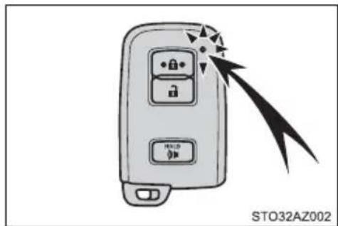
natural_image
Illustration of a smart car with control buttons and a pointer, emitting arrows (no text or symbols on the device itself)■Conditions affecting operation
The smart key system uses weak radio waves. In the following situations, the communication between the electronic key and the vehicle may be affected, preventing the smart key system, wireless remote control and engine immobilizer system from operating properly. (Ways of coping: →P. 523)
- When the electronic key battery is depleted
● Near a TV tower, electric power plant, gas station, radio station, large display, airport or other facility that generates strong radio waves or electrical noise - When carrying a portable radio, cellular phone, cordless phone or other wireless communication device
-
When the electronic key is in contact with, or is covered by the following metallic objects
-
Cards to which aluminum foil is attached
• Cigarette boxes that have aluminum foil inside
• Metallic wallets or bags - Coins
- Hand warmers made of metal
• Media such as CDs and DVDs
- When multiple electronic keys are in the vicinity
- When other wireless keys (that emit radio waves) are being used nearby
- When carrying the electronic key together with the following devices that emit radio waves
- Another vehicle's electronic key or a wireless key that emits radio waves
- Personal computers or personal digital assistants (PDAs)
• Digital audio players - Portable game systems
- If window tint with a metallic content or metallic objects are attached to the back window
- When the electronic key is placed near a battery charger or electronic devices
■Note for the entry function
● Even when the electronic key is within the effective range (detection areas), the system may not operate properly in the following cases:
- The electronic key is too close to the window or outside door handle, near the ground, or in a high place when the doors are locked or unlocked.
- The electronic key is on the instrument panel or floor, or in the console box or glove box when the engine is started or engine switch modes are changed.
- Do not leave the electronic key on top of the instrument panel or near the door pockets when exiting the vehicle. Depending on the radio wave reception conditions, it may be detected by the antenna outside the cabin and the door will become lockable from the outside, possibly trapping the electronic key inside the vehicle.
- As long as the electronic key is within the effective range, the doors may be locked or unlocked by anyone. However, only the doors detecting the electronic key can be used to unlock the vehicle.
● Even if the electronic key is not inside the vehicle, it may be possible to start the engine if the electronic key is near the window.
●The doors may unlock or lock if a large amount of water splashes on the door handle, such as in the rain or in a car wash, when the electronic key is within the effective range. (The doors will automatically be locked after approximately 60 seconds if the doors are not opened and closed.) - If the wireless remote control is used to lock the doors when the electronic key is near the vehicle, there is a possibility that the door may not be unlocked by the entry function. (Use the wireless remote control to unlock the doors.)
- Touching the door lock or unlock sensor while wearing gloves may prevent lock or unlock operation. Remove the gloves and touch the lock sensor again.
- When the lock operation is performed using the lock sensor, recognition signals will be shown up to two consecutive times. After this, no recognition signals will be given.
- If the door handle becomes wet while the electronic key is within the effective range, the door may lock and unlock repeatedly. In this case, follow the following correction procedures to wash the vehicle:
- Place the electronic key in a location 6 ft. (2 m) or more away from the vehicle. (Take care to ensure that the key is not stolen.)
- Set the electronic key to battery-saving mode to disable the smart key system. (→P. 141)
- If the electronic key is inside the vehicle and a door handle becomes wet during a car wash, a message may be shown on the multi-information display and a buzzer will sound outside the vehicle. To turn off the alarm, lock all the doors.
● The lock sensor may not work properly if it comes into contact with ice, snow, mud, etc. Clean the lock sensor and attempt to operate it again, or use the lock sensor on the lower part of the door handle.
- If there is another electronic key in the detection area, it may take slightly longer to unlock the doors after the door handle is gripped.
● A sudden handle operation or a handle operation immediately after entering the effective range may prevent the doors from being unlocked. Touch the door unlock sensor and check that the doors are unlocked before pulling the door handle again.
● Fingernails may scrape against the door during operation of the door handle. Be careful not to injure fingernails or damage the surface of the door.
■Note for the unlocking function
● Gripping the door handle when wearing a glove may not unlock the door.
●A sudden approach to the effective range or door handle may prevent the doors from being unlocked. In this case, return the door handle to the original position and check that the doors unlock before pulling the door handle again.
- If there is another electronic key in the detection area, it may take slightly longer to unlock the doors after the door handle is gripped.
■When the vehicle is not driven for extended periods
● To prevent theft of the vehicle, do not leave the electronic key within 6 ft. (2 m) of the vehicle.
● The smart key system can be deactivated in advance. (→P. 564)
■To operate the system properly
● Make sure to carry the electronic key when operating the system. Do not get the electronic key too close to the vehicle when operating the system from the outside of the vehicle.
● Depending on the position and holding condition of the electronic key, the key may not be detected correctly and the system may not operate properly. (The alarm may go off accidentally, or the door lock prevention function may not operate.)
If the smart key system does not operate properly
● Locking and unlocking the doors: Use the mechanical key. (→P. 523)
● Starting the engine: →P. 523
Customization
Settings (e. g. smart key system) can be changed.
If the smart key system has been deactivated in a customized setting
●Locking and unlocking the doors:
Use the wireless remote control or mechanical key. ( P. 128, 523)
● Starting the engine and changing engine switch modes: →P. 523
●Stopping the engine: →P. 220s
■Certification for the smart key system
For vehicles sold in U.S.A. and New Caledonia
FCC ID: HYQ23ABL
FCC ID: HYQ14FBA
NOTE:
This device complies with part 15 of the FCC Rules. Operation is subject to the following two conditions: (1) This device may not cause harmful interference, and (2) this device must accept any interference received, including interference that may cause undesired operation.
FCC WARNING:
Changes or modifications not expressly approved by the party responsible for compliance could void the user's authority to operate the equipment.
For vehicles sold in Canada
NOTE:
This device complies with Industry Canada's licence-exempt RSSs. Operation is subject to the following two conditions:
(1) This device may not cause interference; and
(2) This device must accept any interference, including interference that may cause undesired operation of the device.
NOTE:
■Caution regarding interference with electronic devices
●People with implantable cardiac pacemakers, cardiac resynchronization therapy-pacemakers or implantable cardioverter defibrillators should keep away from the smart key system antennas. (→P. 138) The radio waves may affect the operation of such devices. If necessary, the entry function can be disabled. Ask your Toyota dealer for details, such as the frequency of radio waves and timing of the emitted radio waves. Then, consult your doctor to see if you should disable the entry function.
- User of any electrical medical device other than implantable cardiac pacemakers, cardiac resynchronization therapy-pacemakers or implantable cardioverter defibrillators should consult the manufacturer of the device for information about its operation under the influence of radio waves. Radio waves could have unexpected effects on the operation of such medical devices. Ask your Toyota dealer for details for disabling the entry function.
Front seats
Adjustment procedure (separated type seats)
Driver's seat
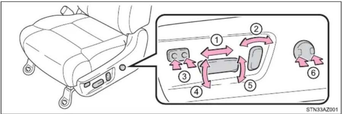
① Seat position adjustment switch
② Seatback angle adjustment switch
③ Seat cushion length adjustment switch (if equipped)
④ Seat cushion (front) angle adjustment switch
⑤ Seat vertical height adjustment switch
⑥ Seat lumbar support adjustment switch
■Passenger's seat
▶ Manual seat
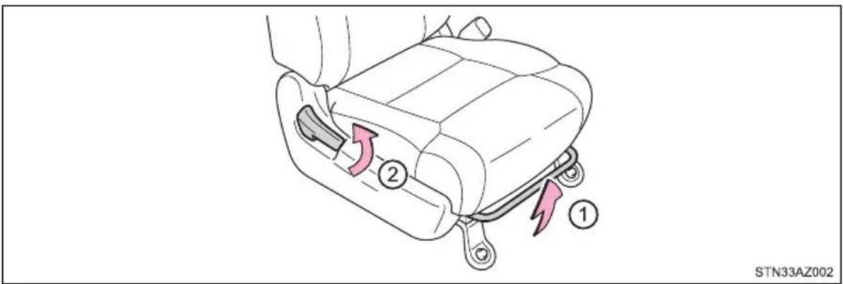
① Seat position adjustment lever Seatback angle adjustment lever
Power seat
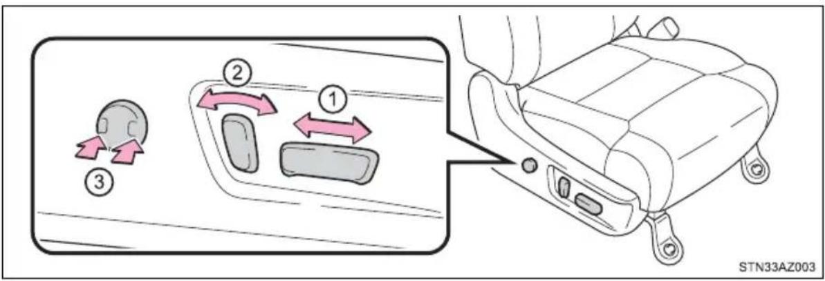
① Seat position adjustment switch
② Seatback angle adjustment switch
③ Seat lumbar support adjustment switch
Adjustment procedure (bench type seats)
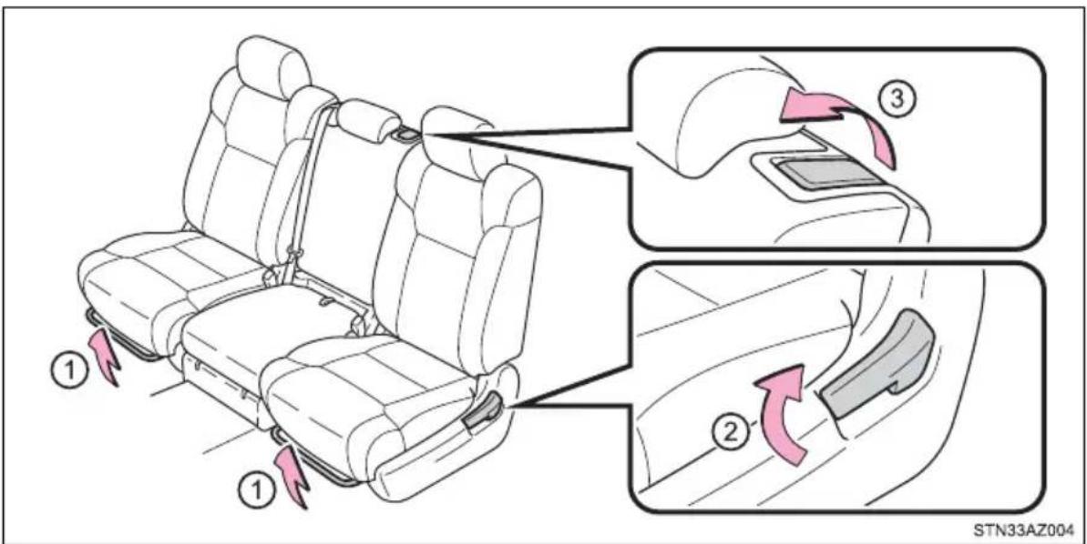
① Seat position adjustment levers
② Seatback angle adjustment levers
③ Center seat seatback angle adjustment lever
■ Power easy access system (vehicles with driving position memory)
The driver's seat and steering wheel move in accordance with engine switch position and the driver's seat belt condition. (→P. 152)

WARNING
■When adjusting the seat position
● Take care when adjusting the seat position to ensure that other passengers are not injured by the moving seat.
- Do not put your hands under the seat or near the moving parts to avoid injury.
Fingers or hands may become jammed in the seat mechanism.
Seat adjustment
● To reduce the risk of sliding under the lap belt during a collision, do not recline the seat more than necessary.
If the seat is too reclined, the lap belt may slide past the hips and apply restraint forces directly to the abdomen, or your neck may contact the shoulder belt, increasing the risk of death or serious injury in the event of an accident.
Adjustments should not be made while driving as the seat may unexpectedly move and cause the driver to lose control of the vehicle.
● Manual seat type only: After adjusting the seat, make sure that the seat is locked in position.
■When adjusting the seat positions
Make sure to leave enough space around the feet so they do not get stuck.
Rear seats
Raising the bottom cushion
1 Use the seat belt hangers to prevent the belts from being tangled.
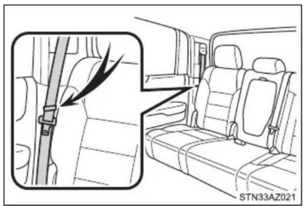
2 Pull and release the lever to unlock while raising the bottom cushion until it locks.
When returning the bottom cushion to its original position, pull and release the lever, then carefully lower the bottom cushion using your other hand.
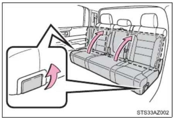

WARNING
■When raising the bottom cushion
Observe the following precautions.
Failure to do so may result in death or serious injury.
●Do not raise the bottom cushion while driving.
- Stop the vehicle on level ground, set the parking brake and shift the shift lever to P.
■When bottom cushion is raised
Do not allow passengers to sit on raised bottom cushion or place anything on storage box (Double Cab models) while driving.
■When returning the seats to their original position
Observe the following precautions.
Failure to do so may result in death or serious injury.
● Be careful not to get your hands or feet pinched in the seat.
Make sure the bottom cushions are securely locked.
- Check that the seat belts are not twisted or caught in the seat.
- Arrange the seat belts in the proper positions for ready use.
● Make sure that there are no objects under the seat cushion or on the loading floor.

NOTICE
■Before raising the bottom cushion
Make sure that there are no objects, such as cushions, on the seat cushion.
●The seat belts must be stowed.
Driving position memory (driver's seat)\*
This feature automatically adjusts the driver's seat, steering wheel and outside rear view mirrors to make entering and exiting the vehicle easier or to suit your preferences.
Power easy access system
The driver's seat and steering wheel are automatically adjusted to allow the driver to enter and exit the vehicle easily.
When all of the following have been performed, the driver's seat and steering wheel are automatically adjusted to a position that allows driver to enter and exit the vehicle easily.
• The shift lever has been shifted to P.
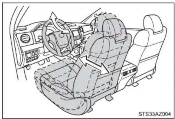
natural_image
Interior view of a car dashboard and seat assembly (no text or symbols visible)- The key has been removed from the engine switch. - The driver's seat belt has been unfastened.
When any of the following has been performed, the driver's seat and steering wheel automatically return to their original positions.
• The key has been inserted into the engine switch.
- The driver's seat belt has been fastened.
Operation of the power easy access system
When exiting the vehicle, the power easy access system may not operate if the seat is already close to the rearmost position, etc.
Customization
The seat movement amount settings of the power easy access system can be customized. (Customizable features: →P. 564)
Driving position memory
Your preferred driving position (the position of the driver's seat, steering wheel and outside rear view mirrors) can be recorded and recalled by pressing a button.
Two different driving positions can be recorded into memory.
■Recording procedure
1 Check that the shift lever is in P.
2 Turn the engine switch to ON.
3 Adjust the driver's seat, steering wheel, and outside rear view mirrors to the desired positions.
4 While pressing the "SET" button, or within 3 seconds after the "SET" button is pressed, press button "1" or "2" until the buzzer sounds.
If the selected button has already been preset, the previously recorded position will be overwritten.
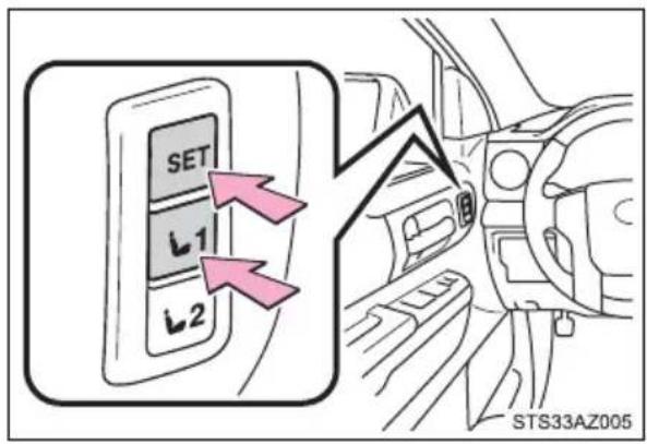
■ Recall procedure
1 Check that the shift lever is in P.
2 Turn the engine switch to ON.
3 Press one of the buttons for the driving position you want to recall until the buzzer sounds.
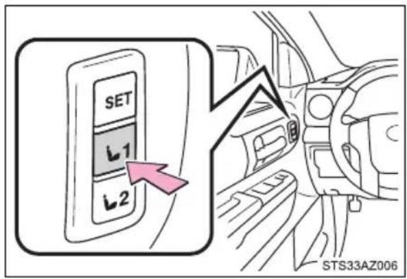
■To stop the position recall operation part-way through
Perform any of the following:
- Press the "SET" button.
- Press button "1" or "2".
- Operate any of the seat adjustment switches (only cancels seat position recall).
- Operate the tilt and telescopic steering control switch (only cancels steering wheel position recall).
■ Seat positions that can be memorized ( P. 147)
The adjusted seat positions can be recorded except for lumbar support positions.
- Operating the driving position memory after the key is removed from the engine switch
Recorded seat positions (except the steering wheel position) can be activated up to 30 seconds after the driver's door is opened, even if the key is removed from the engine switch.
In order to correctly use the driving position memory function
If a seat position is already in the furthest possible position and the seat is operated in the same direction, the recorded position may be slightly different when it is recalled.
Memory recall function
A desired driving position can be recalled linked with the unlocking of the door.
■Registering procedure
Record your driving position to button "1" or "2" before performing the following:
1 Turn the engine switch off and close the driver's door.
2 While pressing the button "1"
or "2", press on the wireless remote control until the signal beeps.
The driving position is recalled when the driver's door is unlocked using the wireless remote control and the driver's door is opened.
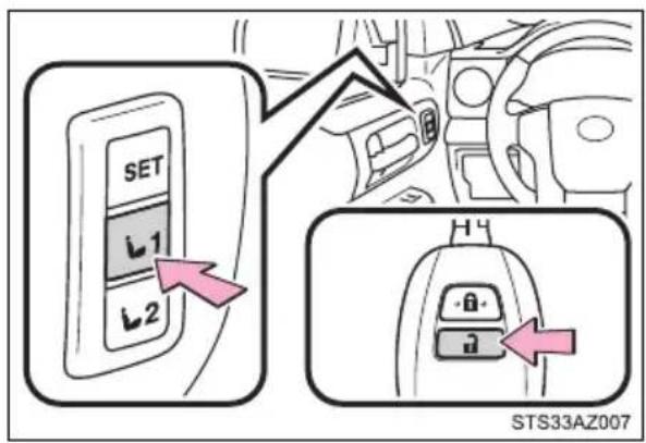
To prevent unintended triggering of the alarm, open and close a door once after a driving position has been recorded. (If a door is not opened within 60 seconds after is pressed, the doors will be locked again and the alarm will automatically be set.) In case that the alarm is triggered, immediately stop the alarm. (→P. 95)
■Cancelation procedure
1 Turn the engine switch off and close the driver's door.
2 While pressing the "SET" button, press on the wireless remote control until you hear 2 beeps.
If the battery is disconnected
The recorded seat positions are erased when the battery is disconnected.

WARNING
■Seat adjustment caution
Take care during seat adjustment so that the seat does not strike the rear passenger or squeeze your body against the steering wheel.
Head restraints
Head restraints are provided for all seats.
Front seats
① Up
Pull the head restraints up.
② Down
Push the head restraint down while pressing the lock release button.
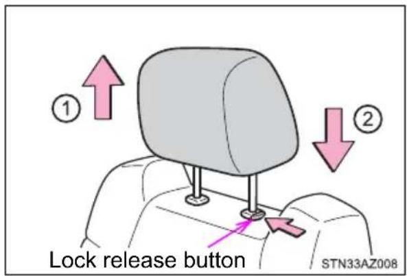
Rear seats
■ Center seat
① Up
Pull the head restraints up.
② Down
Push the head restraint down while pressing the lock release button.
▶ Double Cab models ▶ CrewMax models
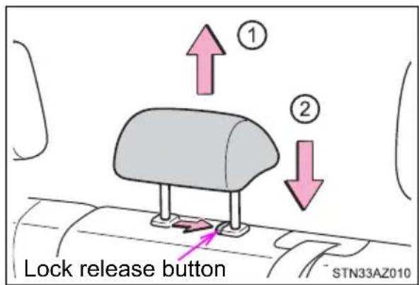
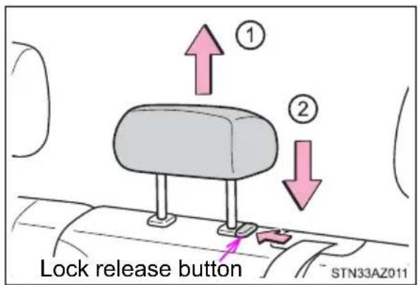
■Outer seat
① Touse
Lift up the head restraint back to the neutral position and then push the head restraint down.
② To fold
Lift up the head restraint while pressing the right lock release button, and fold it forward.
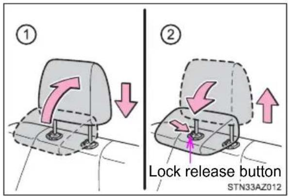
■Removing the head restraints
Front seats and rear center seat (CrewMax models)
Pull the head restraint up while pressing the lock release button.
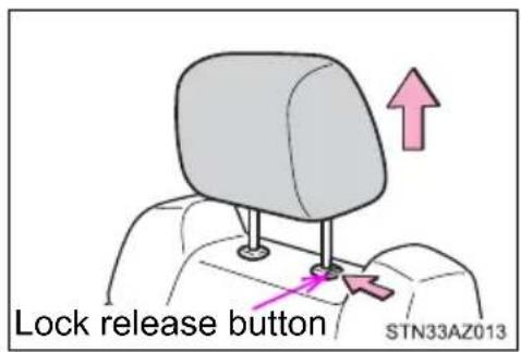
▶ Rear center seat (Double Cab models)
Pull the head restraint up while pressing the lock release button.
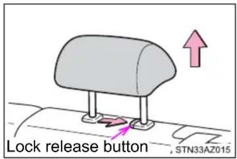
▶ Rear outer seat
Pull the head restraint up while pressing both lock release buttons.
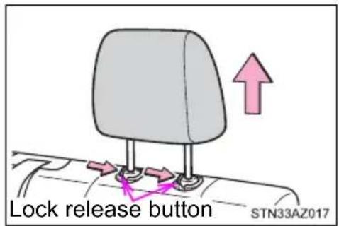
■Installing the head restraints
Front seats and rear center seat (CrewMax models)
Align the head restraint with the installation holes and push it down to the lock position. Press and hold the lock release button when lowering the head restraint.
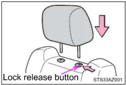
▶ Rear center seat (Double Cab models)
Align the head restraint with the installation holes and push it down to the lock position. Press and hold the lock release button when lowering the head restraint.
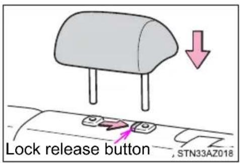
▶ Rear outer seat
Align the head restraint with the installation holes and push it down to the lock position.
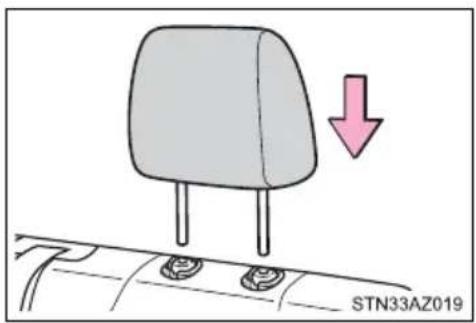
■Adjusting the height of the head restraints (front seats)
Make sure that the head restraints are adjusted so that the center of the head restraint is closest to the top of your ears.
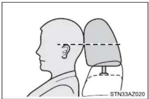
natural_image
Side profile illustration of a human head and neck with a medical device labeled STN33AZ020 (no text or symbols on the diagram itself)■ Adjusting the front center seat (bench type seat) and rear center seat head restraints
Always raise the head restraint one level from the stowed position when using.

WARNING
■Head restraint precautions
Observe the following precautions regarding the head restraints.
Failure to do so may result in death or serious injury.
● Use the head restraints designed for each respective seat.
- Adjust the head restraints to the correct position at all times.
● After adjusting the head restraints, push down on them and make sure they are locked in position.
- Do not drive with the head restraints removed.
Steering wheel
Adjustment procedure (manually adjustable type)
1 Hold the steering wheel and push the lever down.
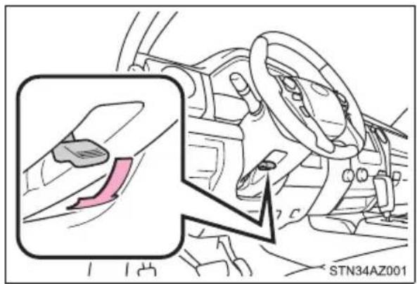
▶ Vehicles with front bench type seat
2 Adjust to the ideal position by moving the steering wheel.
After adjustment, pull the lever up to secure the steering wheel.
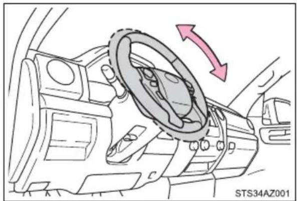
natural_image
Diagram of a car interior showing steering wheel and directional arrows (no text or symbols)▶ Vehicles with front separate type seats
2 Adjust to the ideal position by moving the steering wheel horizontally and vertically.
After adjustment, pull the lever up to secure the steering wheel.
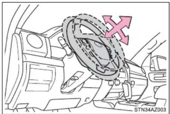
natural_image
Diagram of a car interior showing steering wheel and dashboard with directional arrow (no text or symbols)Adjustment procedure (power-adjustable type)
Operating the switch moves the steering wheel in the following directions:
① Up
② Down
③ Toward the driver
④ Away from the driver
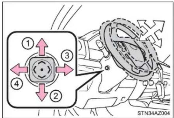
Horn
To sound the horn, press on or close to the mark.
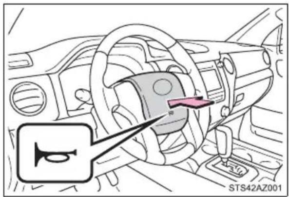
■After adjusting the steering wheel (manual adjustable type)
Make sure that the steering wheel is securely locked.
The horn may not sound if the steering wheel is not securely locked.
(→P. 161)
Auto tilt away (power-adjustable type)
When the engine switch is turned off, the steering wheel returns to its stowed position by moving up and away to enable easier driver entry and exit.
Turning the engine switch to ACC or ON mode will return the steering wheel to the original position.
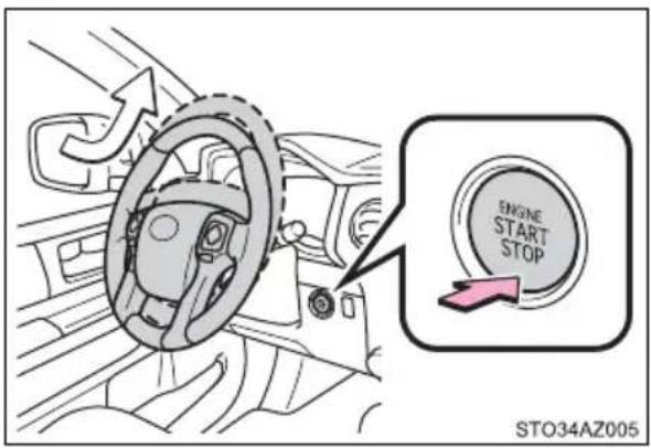
■ The steering wheel can be adjusted when (power adjustable type)
The engine switch is in ON.
■ Automatic adjustment of the steering position (power adjustable type)
A desired steering position can be entered to memory and recalled automatically by the driving position memory system. (→P. 152)
■ Power easy access system (vehicles with driving position memory)
The steering wheel and driver's seat move in accordance with engine switch position and the driver's seat belt condition. (→P. 152)

WARNING
■Caution while driving
Do not adjust the steering wheel while driving.
Doing so may cause the driver to mishandle the vehicle and cause an accident, resulting in death or serious injury.
■ After adjusting the steering wheel (manually adjustable type)
Make sure that the steering wheel is securely locked.
Otherwise, the steering wheel may move suddenly, possibly causing an accident and resulting in death or serious injury.
Inside rear view mirror
The rear view mirror's position can be adjusted to enable sufficient confirmation of the rear view.
Adjusting the height of rear view mirror
The height of the rear view mirror can be adjusted to suit your driving posture.
Adjust the height of the rear view mirror by moving it up and down.
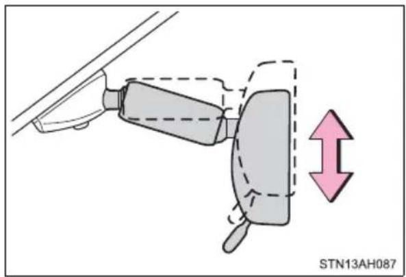
Anti-glare function
▶ Manual anti-glare inside rear view mirror
Reflected light from the headlights of vehicles behind can be reduced by operating the lever.
① Normal position
② Anti-glare position
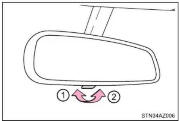
▶ Auto anti-glare inside rear view mirror
Responding to the level of brightness of the headlights of vehicles behind, the reflected light is automatically reduced.
Changing automatic anti-glare function mode
ON/OFF
When the automatic anti-glare function is in ON mode, the indicator illuminates.
The function will set to ON mode each time the engine switch is turned to ON.
Pressing the button turns the function to OFF mode. (The indicator also turns off.)
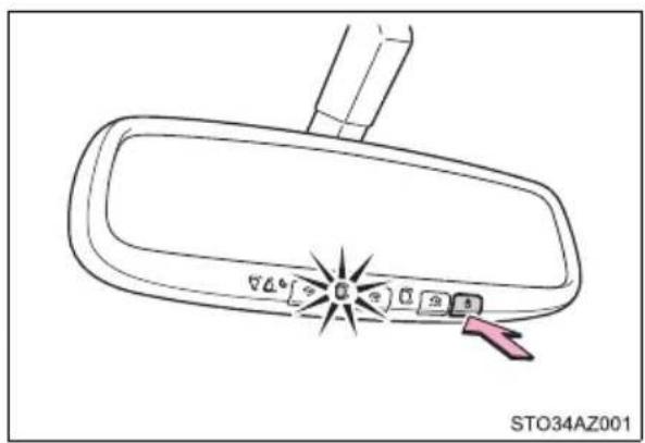
■ To prevent sensor error (vehicles with auto anti-glare inside rear view mirror)
To ensure that the sensors operate properly, do not touch or cover them.
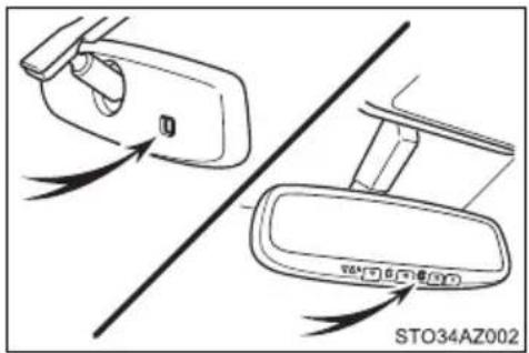
If a sun visor interferes with the mirror
Hold and rotate the mirror to adjust the support.
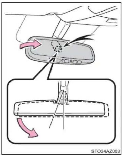

WARNING
Do not adjust the position of the mirror while driving.
Doing so may lead to mishandling of the vehicle and cause an accident resulting in death or serious injury.
Outside rear view mirrors
Adjustment procedure
▶ Manually adjustable type
Adjust the mirror up and down, in or out by pushing the mirror surface.
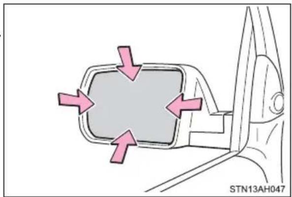
natural_image
Diagram of a car side mirror with directional arrows indicating airflow or movement (no text or symbols)▶ Power-adjustable type (type A)
1 To select a mirror to adjust, press the switch.
① Left
② Right
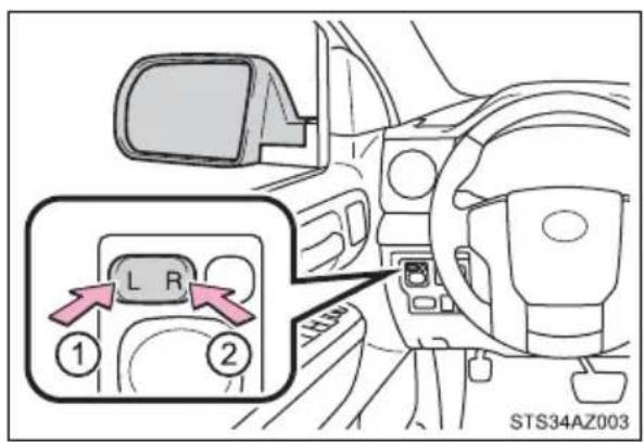
2 To adjust the mirror, press the switch.
① Up
② Right
③ Down
④ Left
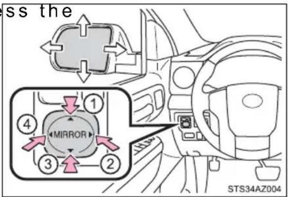
▶ Power-adjustable type (type B)
Upper part mirror:
1 To select a mirror to adjust, press the switch.
① Left
② Right
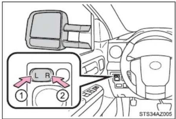
2 To adjust the mirror, press the switch.
① Up
② Right
③ Down
④ Left
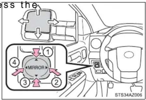
Lower part mirror:
Adjust the mirror up and down, in or out by pushing the mirror surface.
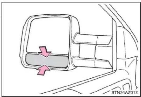
natural_image
Diagram of a car's side mirror showing the left side and right side, with no text or symbols present.Folding the mirrors
From outside
Push the mirror back in the direction of the vehicle's rear.
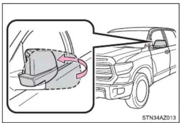
From inside (if equipped)
Press the switch to fold the mirrors.
Press it again to extend them to the original position.
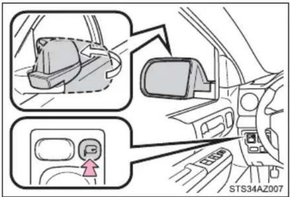
Extending the mirrors (if equipped)
The mirrors can be manually slid outward to improve visibility around wide trailers.
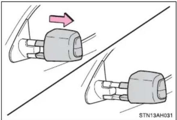
natural_image
Diagram showing two car seatbelt components with a pink arrow indicating rotation, connected by a diagonal line (no text or symbols)Linked mirror function when reversing (if equipped)
When the mirror select switch is in the L or R position, the outside rear view mirrors will automatically angle downwards when the vehicle is reversing in order to give a better view of the ground.
To disable this function, move the mirror select switch to the neutral position (between L and R).
■Adjusting the mirror angle when the vehicle is reversing
With the shift lever in R, adjust the mirror angle at a desired position. The adjusted angle will be memorized and the mirror will automatically tilt to the memorized angle whenever the shift lever is shifted to R from next time.
The memorized downward tilt position of the mirror is linked to the normal position (angle adjusted with the shift lever in other than R). Therefore, if the normal position is changed after adjustment, the tilt position will also change.
When the normal position is changed, readjust the angle in reversing.
■ Recommended mirror angle when towing a trailer (vehicles with extending mirrors)
① Power adjust the upper part of the mirror until an appropriate view is obtained. It is recommended that the outer 2/3 of the upper mirror be filled with images other than the vehicle and trailer.
② Manually adjust the lower part of the mirror until an appropriate view of the towed object is obtained. It is recommended that the outer 2/3 of the lower mirror be filled with images other than the trailer.
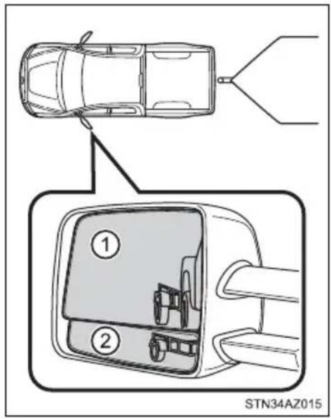
■Mirror operating conditions (power-adjustable type)
The engine switch is in ACC or ON.
■ When the mirrors are fogged up (vehicles with outside rear view mirror defoggers)
Turn on the mirror defoggers to defog the mirrors. ( P. 342, 349)
■ Automatic adjustment of the mirror angle (vehicles with driving position memory)
A desired mirror face angle can be entered to memory and recalled automatically by the driving position memory. ( P. 152)
■Auto anti-glare function (if equipped)
When the anti-glare inside rear view mirror is set to automatic mode, the outside rear view mirrors will activate in conjunction with the anti-glare inside rear view mirror to reduce reflected light. ( P. 165)

WARNING
■ Important points while driving
Observe the following precautions while driving.
Failure to do so may result in loss of control of the vehicle and cause an accident, resulting in death or serious injury.
- Do not adjust the mirrors while driving.
●Do not drive with the mirrors folded.
● Both the driver and passenger side mirrors must be extended and properly adjusted before driving.
■When a mirror is moving (power-adjustable type)
To avoid personal injury and mirror malfunction, be careful not to get your hand caught by the moving mirror.
■ When the mirror defoggers are operating (vehicles with outside rear view mirror defoggers)
Do not touch the rear view mirror surfaces, as they can become very hot and burn you.
Power windows
Opening and closing procedures
The power windows can be opened and closed using the switches.
Operating the switch moves the windows as follows:
▶ Type A
① Closing
② Opening
③ One-touch opening * (driver's window only)
*: To stop the window partway, operate the switch in the opposite direction.
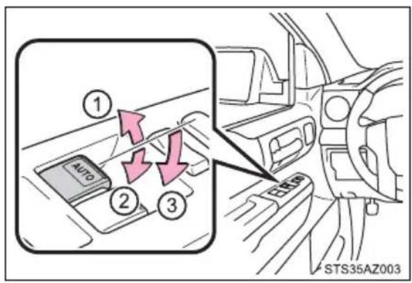
▶ Type B
① Closing
② One-touch closing ^* (front seat windows)
③ Opening
④ One-touch opening* (front seat windows)
*: To stop the window partway, operate the switch in the opposite direction.
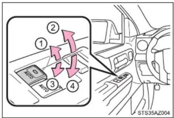
Window lock switch
Press the switch down to lock the passenger window switches.
Use this switch to prevent children from accidentally opening or closing a passenger window.
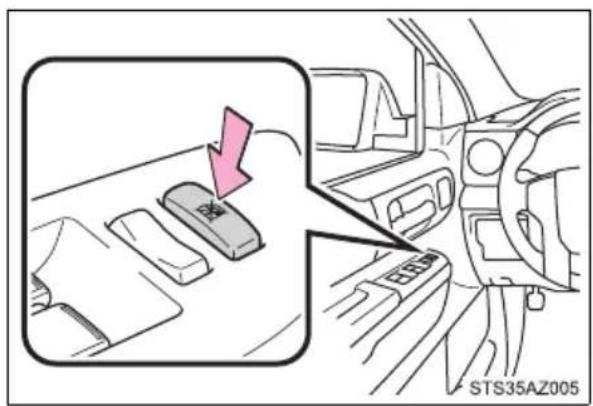
■The power windows can be operated when
The engine switch is in ON.
- Operating the power windows after turning the engine off
The power windows can be operated for approximately 43 seconds after the engine switch is turned to ACC or OFF. They cannot, however, be operated once either front door is opened.
■Jam protection function (type B only)
If an object becomes caught between the window and the window frame, window travel is stopped and the window is opened slightly.
■When the power window does not close normally (type B only)
If the jam protection function is operating abnormally and a window cannot be closed, perform the following operations using the power window switch on the relevant door.
● After stopping the vehicle, the window can be closed by holding the power window switch in the one-touch closing position while the engine switch is turned to ON.
- If the window still cannot be closed even by carrying out the operation as explained above, initialize the function by performing the following procedure.
1 Hold the power window switch in the one-touch closing position. Continue holding the switch for a further 6 seconds after the window has closed.
2 Hold the power window switch in the one-touch opening position. Continue holding the switch for a further 2 seconds after the window has opened completely.
3 Hold the power window switch in the one-touch closing position once again. Continue holding the switch for a further 2 seconds after the window has closed.
If you release the switch while the window is moving, start again from the beginning.
If the window continues to close but then re-open slightly even after performing the above procedure correctly, have the vehicle inspected by your Toyota dealer.

WARNING
Observe the following precautions.
Failure to do so may result in death or serious injury.
■Closing the windows
The driver is responsible for all the power window operations, including the operation for the passengers. In order to prevent accidental operation, especially by a child, do not let a child operate the power windows. It is possible for children and other passengers to have body parts caught in the power window. Also, when riding with a child, it is recommended to use the window lock switch. (→P. 172)
- Check to make sure that all passengers do not have any part of their body in a position where it could be caught when a window is being operated.
- When exiting the vehicle, turn the engine switch off, carry the key and exit the vehicle along with the child. There may be accidental operation, due to mischief, etc., that may possibly lead to an accident.
■Jam protection function (type B only)
● Never use any part of your body to intentionally activate the jam protection function.
●The jam protection function may not work if something gets caught just before the window fully closes.
Back window\*
Opening and closing
Open/close
Push the lock release lever and slide the back window.

■ Closing the back window
Make sure that the back window is securely closed after closing it.

WARNING
■Caution while driving
Keep the back window closed.
This not only keeps personal belongings from being thrown out, but also prevents exhaust gases from entering the vehicle.
Power back window\*
Opening and closing
▶ Double Cab models
① Opening
② Closing
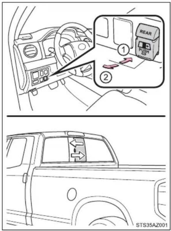
▶ CrewMax models
① Opening
② Closing
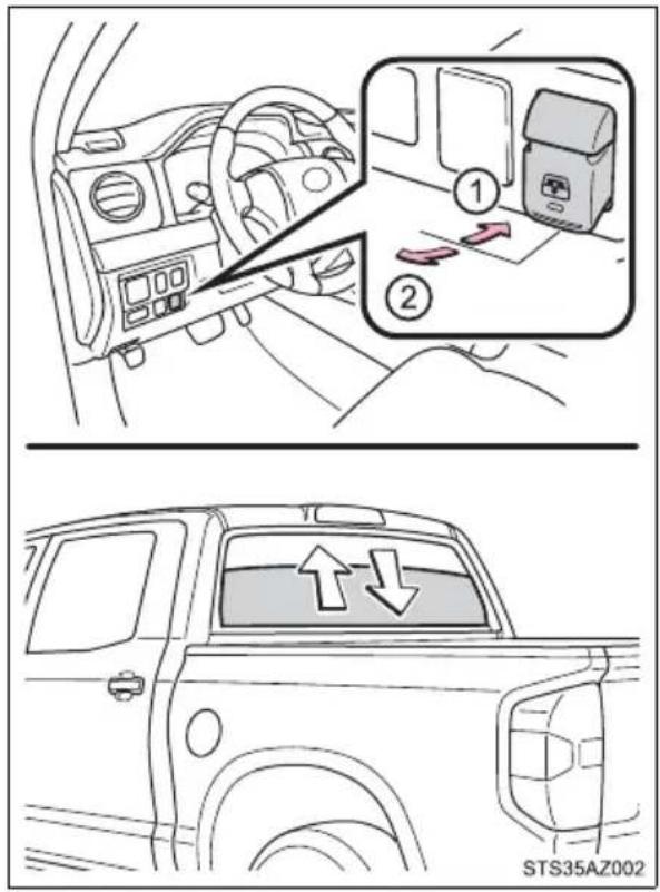
■The power back window can be operated when
The engine switch is in ON.
■Operating the power back windows after turning the engine off
The power back windows can be operated for approximately 43 seconds after the engine switch is turned to ACC or OFF. They cannot, however, be operated once either front door is opened.

WARNING
■ Closing the back window
Observe the following precautions.
Failure to do so may result in death or serious injury.
The driver is responsible for all the power back window operations, including the operation for the passengers. In order to prevent accidental operation, especially by a child, do not let a child operate the power back window. It is possible for children and other passengers to have body parts caught in the power back window.
- Check to make sure that all passengers do not have any part of their body in a position where it could be caught when a window is being operated.
- When exiting the vehicle, turn the engine switch off, carry the key and exit the vehicle along with the child. There may be accidental operation, due to mischief, etc., that may possibly lead to an accident.
■Caution while driving
Keep the back window closed.
This not only keeps personal belongings from being thrown out, but also prevents exhaust gases from entering the vehicle.
Moon roof\*
Use the overhead switches to open and close the moon roof and tilt it up and down.
Opening and closing
① Opens the moon roof*
② Closes the moon roof*
*: Lightly press either way of the moon roof switch to stop the moon roof partway.
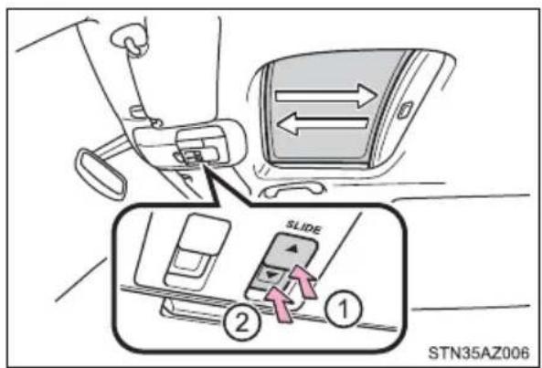
Tilting up and down
① Tilts the moon roof up*
② Tilts the moon roof down*
*: Lightly press either way of the moon roof switch to stop the moon roof partway.
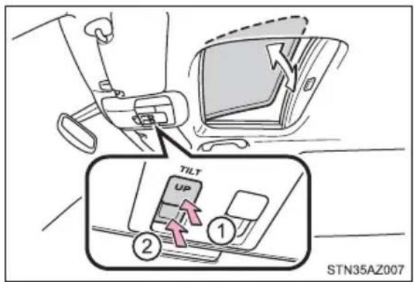
■The moon roof can be operated when
The engine switch in ON.
■Operating the moon roof after turning the engine off
The moon roof can be operated for approximately 43 seconds after the engine switch is turned to ACC or OFF. It cannot, however, be operated once either front door is opened.
Jam protection function
If an object is detected between the moon roof and the frame while the moon roof is closing or tilting down, travel is stopped and the moon roof opens slightly.
Sunshade
The sunshade can be opened and closed manually. However, the sunshade will open automatically when the moon roof is opened.
■Door lock linked moon roof operation
The moon roof can be opened and closed using the key. ( P. 127)
■When the moon roof does not close normally
Perform the following procedure:
- If the moon roof closes but then re-opens slightly
1 Stop the vehicle.
2 Press and hold the “▼” (sliding close) switch ^1 .
The moon roof will close, reopen and pause for approximately 10 seconds. ^2 Then it will close again, tilt up and pause for approximately 1 second. Finally, it will tilt down, open and close.
3 Check to make sure that the moon roof is completely closed and then release the switch.
- If the moon roof tilts down but then tilts back up
1 Stop the vehicle.
2 Press and hold the "UP" (tilt up) switch *1 until the moon roof moves into the tilt up position and stops.
3 Release the "UP" (tilt up) switch once and then press and hold the "UP" (tilt up) switch again. *1
The moon roof will pause for approximately 10 seconds in the tilt up position. ^*2 Then it will adjust slightly and pause for approximately 1 second. Finally, it will tilt down, open and close.
4 Check to make sure that the moon roof is completely closed and then release the switch.
*1: If the switch is released at the incorrect time, the procedure will have to be performed again from the beginning.
*2: If the switch is released after the above mentioned 10 seconds pause, automatic operation will be disabled. In that case, press and hold the “▼” (sliding close) or “UP” (tilt up) switch, and the moon roof will tilt up and pause for approximately 1 second. Then it will tilt down, open and close. Check to make sure that the moon roof is completely closed and then release the switch.
If the moon roof does not fully close even after performing the above procedure correctly, have the vehicle inspected by your Toyota dealer.
■Moon roof open reminder function
The buzzer sounds and a message is shown on the multi-information display in the instrument cluster when the engine switch is turned off and the driver's door is opened with the moon roof open.
■When the battery is disconnected
The moon roof must be initialized in order to ensure proper operation.
1 Push and hold the switch toward the "UP" (tilt up) side or "▼" (sliding close) side.
2 After the moon roof will tilt up and down, release the switch.
3 To ensure the initialization is complete, make sure automatic opening and closing functions work properly.
■ Customization that can be configured at Toyota dealer
Settings (e.g. linked door lock operation) can be changed. (Customizable features: →P. 564)

WARNING
Observe the following precautions.
Failure to do so may cause death or serious injury.
■ Opening the moon roof
- Do not allow any passengers to put their hands or heads outside the vehicle while it is moving.
- Do not sit on top of the moon roof.
■ Closing the moon roof
The driver is responsible for moon roof opening and closing operations. In order to prevent accidental operation, especially by a child, do not let a child operate the moon roof. It is possible for children and other passengers to have body parts caught in the moon roof.
- Check to make sure that all passengers do not have any part of their body in a position where it could be caught when the moon roof is being operated.
- When using the key and operating the moon roof, operate the moon roof after checking to make sure that there is no possibility of any passenger having any of their body parts caught in the moon roof. Also, do not let a child operate moon roof by the key. It is possible for children and other passengers to get caught in the moon roof.
- When exiting the vehicle, turn the engine switch off, carry the key and exit the vehicle along with the child. There may be accidental operation, due to mischief, etc., that may possibly lead to an accident.
Jam protection function
● Never use any part of your body to intentionally activate the jam protection function.
●The jam protection function may not work if something gets caught just before the moon roof fully closes.
Driving
4
4-1. Before driving
Driving the vehicle...... 184
Cargo and luggage ...... 192
Vehicle load limits 195
Trailer towing.... 197
Dinghy towing 216
4-2. Driving procedures
Engine (ignition) switch (vehicles without a smart key system)...... 217
Engine (ignition) switch (vehicles with a smart key system)...... 219
Automatic transmission..... 225
Turn signal lever.... 232
Parking brake.... 233
4-3. Operating the lights and wipers
Headlight switch.... 234
Automatic High Beam ..... 239
Fog light switch 244
Windshield wipers and washer 245
4-4. Refueling
Opening the fuel tank cap 248
4-5. Using the driving support systems
Toyota Safety Sense P ..... 252
PCS (Pre-Collision System).... 260
LDA (Lane Departure Alert) 272
Dynamic radar cruise control 280
Cruise control.... 294
Intuitive parking assist..... 298
BSM (Blind Spot Monitor) ...... 305
Four-wheel drive system... 315
AUTO LSD system...... 318
Driving assist systems ..... 320
Trailer brake controller ..... 327
4-6. Driving tips
Winter driving tips ...... 331
Off-road precautions ..... 335
Driving the vehicle
The following procedures should be observed to ensure safe driving:
Starting the engine
→P.217
Driving
1 With the brake pedal depressed, shift the shift lever to D. ( P. 225)
2 Release the parking brake. ( P. 233)
3 Gradually release the brake pedal and gently depress the accelerator pedal to accelerate the vehicle.
Stopping
1 With the shift lever in D, depress the brake pedal.
2 If necessary, set the parking brake.
If the vehicle is to be stopped for an extended period of time, shift the shift lever to P or N. ( P. 225)
Parking the vehicle
1 With the shift lever in D, depress the brake pedal.
2 Set the parking brake ( P. 233), and shift the shift lever to P ( P. 225).
3 Turn the engine switch to OFF to stop the engine.
4 Lock the door, making sure that you have the key on your person. If parking on a hill, block the wheels as needed.
Starting off on a steep uphill
1 Make sure that the parking brake is set and shift the shift lever to D.
2 Gently depress the accelerator pedal.
3 Release the parking brake.
- Driving in the rain
- Drive carefully when it is raining, because visibility will be reduced, the windows may become fogged-up, and the road will be slippery.
- Drive carefully when it starts to rain, because the road surface will be especially slippery.
● Refrain from high speeds when driving on an expressway in the rain, because there may be a layer of water between the tires and the road surface, preventing the steering and brakes from operating properly.
■Engine speed while driving
In the following conditions, the engine speed may become high while driving. This is due to automatic up-shifting control or down-shifting implementation to meet driving conditions. It does not indicate sudden acceleration.
●The vehicle is judged to be driving uphill or downhill
- When the accelerator pedal is released
- When the brake pedal is depressed while TOW/HAUL mode is selected (if equipped)
■Restraining the engine output (Brake Override System)
- When the accelerator and brake pedals are depressed at the same time, the engine output may be restrained.
● A warning message is displayed on the multi-information display while the system is operating.
■Restraining sudden start (Drive-Start Control)
- When the following unusual operation is performed, the engine output may be restrained.
- When the shift lever is shifted from R to D, D to R, N to R, P to D, or P to R (D includes S) with the accelerator pedal depressed, a warning message appears on the multi-information display.
- When the accelerator pedal is depressed too much while the vehicle is in reverse.
● While Drive-Start Control is being activated, your vehicle may have trouble escaping from the mud or fresh snow. In such case, perform the following actions to cancel Drive-Start Control so that the vehicle may become able to escape from the mud or fresh snow. - Deactivate TRAC (→P. 323)
- When the AUTO LSD system is turned on. (→P. 318)
- 4WD models: The four-wheel drive control switch is in "4L" position. (→P. 315)
■Breaking in your new Toyota
To extend the life of the vehicle, observing the following precautions is recommended:
●For the first 200 miles (300 km):
Avoid sudden stops.
●For the first 500 miles (800 km):
Do not tow a trailer.
●For the first 1000 miles (1600 km):
- Do not drive at extremely high speeds.
- Avoid sudden acceleration.
- Do not drive continuously in low gears.
- Do not drive at a constant speed for extended periods.
■Drum-in-disc type parking brake system
Your vehicle has a drum-in-disc type parking brake system. This type of brake system needs bedding-down of the brake shoes periodically or whenever the parking brake shoes and/or drum are replaced. Have your Toyota dealer perform the bedding down operation.
■Operating your vehicle in a foreign country
Comply with the relevant vehicle registration laws and confirm the availability of the correct fuel. ( P. 551)
■When turning off the engine
The emission system operating sounds may continue for a short time after the engine is turned off. This is not a malfunction, and helps to ensure optimal performance of the emission system.

WARNING
Observe the following precautions.
Failure to do so may result in death or serious injury.
■When starting the vehicle
Always keep your foot on the brake pedal while stopped with the engine running. This prevents the vehicle from creeping.
■When driving the vehicle
- Do not drive if you are unfamiliar with the location of the brake and accelerator pedals to avoid depressing the wrong pedal.
- Accidentally depressing the accelerator pedal instead of the brake pedal will result in sudden acceleration that may lead to an accident.
- When backing up, you may twist your body around, leading to difficulty in operating the pedals. Make sure to operate the pedals properly.
- Make sure to keep a correct driving posture even when moving the vehicle only slightly. This allows you to depress the brake and accelerator pedals properly.
- Depress the brake pedal using your right foot. Depressing the brake pedal using your left foot may delay response in an emergency, resulting in an accident.
- Do not drive the vehicle over or stop the vehicle near flammable materials. The exhaust system and exhaust gases can be extremely hot. These hot parts may cause a fire if there is any flammable material nearby.
During normal driving, do not turn off the engine. Turning the engine off while driving will not cause loss of steering or braking control, but the power assist to these systems will be lost. This will make it more difficult to steer and brake, so you should pull over and stop the vehicle as soon as it is safe to do so.
However, in the event of an emergency, such as if it becomes impossible to stop the vehicle in the normal way: →P. 475
- Use engine braking (downshift) to maintain a safe speed when driving down a steep hill.
Using the brakes continuously may cause the brakes to overheat and lose effectiveness. ( P. 225)
- Do not adjust the positions of the steering wheel, the seat, or the inside or outside rear view mirrors while driving.
Doing so may result in a loss of vehicle control.
● Always check that all passengers' arms, heads or other parts of their body are not outside the vehicle.

WARNING
Observe the following precautions.
Failure to do so may result in death or serious injury.
■When driving the vehicle
- Do not drive in excess of the speed limit. Even if the legal speed limit permits it, do not drive over 85 mph (140 km/h) unless your vehicle has high-speed capability tires. Driving over 85 mph (140 km/h) may result in tire failure, loss of control and possible injury. Be sure to consult a tire dealer to determine whether the tires on your vehicle are high-speed capability tires or not before driving at such speeds.
■When driving on slippery road surfaces
● Sudden braking, acceleration and steering may cause tire slippage and reduce your ability to control the vehicle.
● Sudden acceleration, engine braking due to shifting, or changes in engine speed could cause the vehicle to skid.
● After driving through a puddle, lightly depress the brake pedal to make sure that the brakes are functioning properly. Wet brake pads may prevent the brakes from functioning properly. If the brakes on only one side are wet and not functioning properly, steering control may be affected.
■When shifting the shift lever
- Do not let the vehicle roll backward while the shift lever is in a driving position, or roll forward while the shift lever is in R.
Doing so may cause the engine to stall or lead to poor brake and steering performance, resulting in an accident or damage to the vehicle. - Do not shift the shift lever to P while the vehicle is moving.
Doing so can damage the transmission and may result in a loss of vehicle control. - Do not shift the shift lever to R while the vehicle is moving forward.
Doing so can damage the transmission and may result in a loss of vehicle control. - Do not shift the shift lever to a driving position while the vehicle is moving backward.
Doing so can damage the transmission and may result in a loss of vehicle control. - Moving the shift lever to N while the vehicle is moving will disengage the engine from the transmission. Engine braking is not available when N is selected.
- Be careful not to shift the shift lever with the accelerator pedal depressed.
Shifting the shift lever to a gear other than P or N may lead to moving unexpectedly of the vehicle that may cause an accident.

WARNING
If you hear a squealing or scraping noise (brake pad wear limit indicators)
Have the brake pads checked and replaced by your Toyota dealer as soon as possible.
Rotor damage may result if the pads are not replaced when needed.
It is dangerous to drive the vehicle when the wear limits of the brake pads and/or those of the brake discs are exceeded.
■When the vehicle is stopped
- Do not race the engine.
If the vehicle is in any gear other than P or N, the vehicle may move suddenly and unexpectedly, causing an accident. - In order to prevent accidents due to the vehicle rolling away, always keep depressing the brake pedal while the engine is running, and apply the parking brake as necessary.
- If the vehicle is stopped on an incline, in order to prevent accidents caused by the vehicle rolling forward or backward, always depress the brake pedal and securely apply the parking brake as needed.
●Avoid revving or racing the engine.
Running the engine at high speed while the vehicle is stopped may cause the exhaust system to overheat, which could result in a fire if combustible material is nearby.
■When the vehicle is parked
- Do not leave glasses, cigarette lighters, spray cans, or soft drink cans in the vehicle when it is in the sun.
Doing so may result in the following:
- Gas may leak from a cigarette lighter or spray can, and may lead to a fire.
- The temperature inside the vehicle may cause the plastic lenses and plastic material of glasses to deform or crack.
- Soft drink cans may rupture, causing the contents to spray over the interior of the vehicle, and may also cause a short circuit in the vehicle's electrical components.
- Do not leave cigarette lighters in the vehicle. If a cigarette lighter is in a place such as the glove box or on the floor, it may be lit accidentally when luggage is loaded or the seat is adjusted, causing a fire.
- Do not attach adhesive discs to the windshield or windows. Do not place containers such as air fresheners on the instrument panel or dashboard. Adhesive discs or containers may act as lenses, causing a fire in the vehicle.

WARNING
- Do not leave a door or window open if the curved glass is coated with a metallized film such as a silver-colored one. Reflected sunlight may cause the glass to act as a lens, causing a fire.
● Always apply the parking brake, shift the shift lever to P, stop the engine and lock the vehicle.
Do not leave the vehicle unattended while the engine is running. If the vehicle is parked with the shift lever in P but the parking brake is not set, the vehicle may start to move, possibly leading to an accident. - Do not touch the exhaust pipes while the engine is running or immediately after turning the engine off.
Doing so may cause burns. - 4WD models: If the shift lever is moved before the “4LO” indicator turns on/off, the transfer mode may not be shifted completely. The transfer mode disengages both the front and rear driveshafts from the powertrain and allows the vehicle to move regardless of the shift position. (At this time, the indicator blinks and the buzzer sounds.)
Therefore, the vehicle is free to roll even if the automatic transmission is in P. You or someone else could be seriously injured. You must complete the shifting of the transfer mode. ( P. 315)
■When taking a nap in the vehicle
Always turn the engine off. Otherwise, if you accidentally move the shift lever or depress the accelerator pedal, this could cause an accident or fire due to engine overheating. Additionally, if the vehicle is parked in a poorly ventilated area, exhaust gases may collect and enter the vehicle, leading to death or a serious health hazard.
When braking
- When the brakes are wet, drive more cautiously.
Braking distance increases when the brakes are wet, and this may cause one side of the vehicle to brake differently than the other side. Also, the parking brake may not securely hold the vehicle. - If the brake booster device does not operate, do not follow other vehicles closely and avoid hills or sharp turns that require braking.
In this case, braking is still possible, but the brake pedal should be depressed more firmly than usual. Also, the braking distance will increase. Have your brakes fixed immediately. - Do not pump the brake pedal if the engine stalls.
Each push on the brake pedal uses up the reserve for the power-assisted brakes.
● The brake system consists of 2 individual hydraulic systems; if one of the systems fails, the other will still operate. In this case, the brake pedal should be depressed more firmly than usual and the braking distance will increase. Have your brakes fixed immediately.

NOTICE
■When driving the vehicle
- Do not depress the accelerator and brake pedals at the same time during driving, as this may restrain the engine output.
- Do not use the accelerator pedal or depress the accelerator and brake pedals at the same time to hold the vehicle on a hill.
■When parking the vehicle
Always set the parking brake, and shift the shift lever to P. Failure to do so may cause the vehicle to move or the vehicle may move suddenly if the accelerator pedal is accidentally depressed.
■Avoiding damage to vehicle parts
- Do not turn the steering wheel fully in either direction and hold it there for an extended period of time.
Doing so may damage the power steering pump. - When driving over bumps in the road, drive as slowly as possible to avoid damaging the wheels, underside of the vehicle, etc.
If you get a flat tire while driving
A flat or damaged tire may cause the following situations. Hold the steering wheel firmly and gradually depress the brake pedal to slow down the vehicle.
It may be difficult to control your vehicle.
●The vehicle will make abnormal sounds or vibrations.
●The vehicle will lean abnormally.
Information on what to do in case of a flat tire ( P. 506)
■When encountering flooded roads
Do not drive on a road that has flooded after heavy rain, etc. Doing so may cause the following serious damage to the vehicle:
Engine stalling
●Short in electrical components
●Engine damage caused by water immersion
In the event that you drive on a flooded road and the vehicle is flooded, be sure to have your Toyota dealer check the following:
Brake function
● Changes in quantity and quality of oil and fluid used for the engine, transmission, transfer (4WD models) differentials, etc.
● Lubricant condition for the propeller shaft, bearings and suspension joints (where possible), and the function of all joints, bearings, etc.
Cargo and luggage
Take notice of the following information about storage precautions, cargo capacity and load:
Capacity and distribution
Cargo capacity depends on the total weight of the occupants.
(Cargo capacity) = (Total load capacity) - (Total weight of occupants)
Steps for Determining Correct Load Limit —
(1) Locate the statement “The combined weight of occupants and cargo should never exceed XXX kg or XXX lbs.” on your vehicle’s placard.
(2) Determine the combined weight of the driver and passengers that will be riding in your vehicle.
(3) Subtract the combined weight of the driver and passengers from XXX kg or XXX lbs.
(4) The resulting figure equals the available amount of cargo and luggage load capacity.
For example, if the “XXX” amount equals 1400 lbs. and there will be five 150 lb passengers in your vehicle, the amount of available cargo and luggage load capacity is 650 lbs. (1400 – 750 (5 × 150) = 650 lbs.)
(5) Determine the combined weight of luggage and cargo being loaded on the vehicle. That weight may not safely exceed the available cargo and luggage load capacity calculated in Step 4.
(6) If your vehicle will be towing a trailer, load from your trailer will be transferred to your vehicle. Consult this manual to determine how this reduces the available cargo and luggage load capacity of your vehicle. (→P. 195)
Calculation formula for your vehicle
① Cargo capacity
② Total load capacity (vehicle capacity weight) ( P. 538)
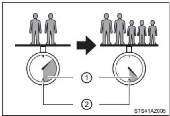
flowchart
graph TD
    A["Human silhouette"] --> B["Group representation"]
    B --> C["Step ①: Two separate pie slices with shaded regions"]
    B --> D["Step ②: Two separate pie slices with shaded regions"]
    style A fill:#f9f,stroke:#333
    style B fill:#ccf,stroke:#333
    style C fill:#cfc,stroke:#333
    style D fill:#fcc,stroke:#333
When 2 people with the combined weight of A lb. (kg) are riding in your vehicle, which has a total load capacity (vehicle capacity weight) of B lb. (kg), the available amount of cargo and luggage load capacity will be C lb. (kg) as follows:
B^2 lb. (kg) - A^1 lb. (kg) = C^*3 lb. (kg)
*1: A = Weight of people
*2: B = Total load capacity
*3: C = Available cargo and luggage load
In this condition, if 3 more passengers with the combined weight of D lb. (kg) get on, the available cargo and luggage load will be reduced E lb. (kg) as follows:
C lb. (kg) - D*4 lb. (kg) = E*5 lb. (kg)
*4: D = Additional weight of people
*5: E = Available cargo and luggage load
As shown in the above example, if the number of occupants increases, the cargo and luggage load will be reduced by an amount that equals the increased weight due to the additional occupants. In other words, if an increase in the number of occupants causes an excess of the total load capacity (combined weight of occupants plus cargo and luggage load), you must reduce the cargo and luggage on your vehicle.

WARNING
■Things that must not be carried in the luggage compartment
The following things may cause a fire if loaded in the luggage compartment:
●Receptacles containing gasoline
Aerosol cans
■Storage precautions
Observe the following precautions.
Failure to do so may prevent the pedals from being depressed properly, may block the driver's vision, or may result in items hitting the driver or passengers, possibly causing an accident.
- Do not stack anything behind the front seats higher than the seat-backs.
- Do not place cargo or luggage in or on the following locations.
- At the feet of the driver
- On the front passenger or rear seats (when stacking items)
- On the instrument panel
- On the dashboard
- On the auxiliary box or tray that has no lid
- Secure all items in the occupant compartment.
- Never allow anyone to ride in the rear deck. It is not designed for passengers. They should ride in their seats with their seat belts properly fastened. Otherwise, they are much more likely to suffer death or serious bodily injury, in the event of sudden braking, sudden swerving or an accident.
■Capacity and distribution
- Do not exceed the maximum axle weight rating or the total vehicle weight rating.
Even if the total load of occupant's weight and the cargo load is less than the total load capacity, do not apply the load unevenly. Improper loading may cause deterioration of steering or braking control which may cause death or serious injury.
Vehicle load limits
Vehicle load limits include total load capacity, seating capacity, TWR (Trailer Weight Rating) and cargo capacity.
Total load capacity (vehicle capacity weight): →P. 538
Total load capacity means the combined weight of occupants, cargo and luggage.
♦ Seating capacity: →P. 537
Seating capacity means the maximum number of occupants whose estimated average weight is 150 lb. (68 kg) per person.
Even if the number of occupants are within the seating capacity, do not exceed the total load capacity.
◆ TWR (Trailer Weight Rating): →P. 201
TWR means the maximum gross trailer weight (trailer weight plus its cargo weight) that your vehicle is able to tow.
Cargo capacity
Cargo capacity may increase or decrease depending on the weight and the number of occupants.
■Total load capacity and seating capacity
These details are also described on the tire and loading information label. ( P. 442)

WARNING
■Overloading the vehicle
Do not overload the vehicle.
It may not only cause damage to the tires, but also degrade steering and braking ability, resulting in an accident.
Trailer towing
Your vehicle is designed primarily as a passenger-and-load-carrying vehicle. Towing a trailer can have an adverse impact on handling, performance, braking, durability, and fuel consumption. For your safety and the safety of others, you must not overload your vehicle or trailer. You must also ensure that you are using appropriate towing equipment, that the towing equipment has been installed correctly and used properly, and that you employ the requisite driving habits. (→P. 214)
Vehicle-trailer stability and braking performance are affected by trailer stability, brake performance and setting, trailer brakes, the hitch and hitch systems (if equipped).
To tow a trailer safely, use extreme care and drive the vehicle in accordance with your trailer's characteristics and operating conditions.
Toyota warranties do not apply to damage or malfunction caused by towing a trailer for commercial purposes.
Contact your Toyota dealer for further information about additional requirements such as a towing kit, etc.
Towing related terms
■GCWR (Gross Combination Weight Rating)
The maximum allowable gross combination weight. The gross combination weight is the sum of the total vehicle weight (including the occupants, cargo and any optional equipment installed on the vehicle) and the weight of the trailer being towed (including the cargo in the trailer).
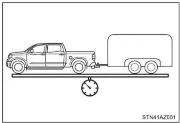
natural_image
Line drawing of a pickup truck on a flatbed trailer with a speedometer, no text or symbols present■GVWR (Gross Vehicle Weight Rating)
The maximum allowable gross vehicle weight. The gross vehicle weight is the total weight of the vehicle. When towing a trailer, it is the sum of the vehicle weight (including the occupants, cargo and any optional equipment installed on the vehicle) and the tongue weight.
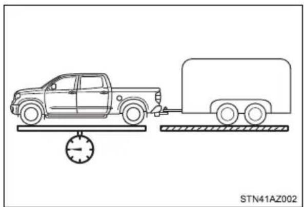
natural_image
Line drawing of a pickup truck on a platform with a speedometer, connected to a cargo trailer (no text or symbols)■ GAWR (Gross Axle Weight Rating)
The maximum allowable gross axle weight. The gross axle weight is the load placed on each axle (front and rear).
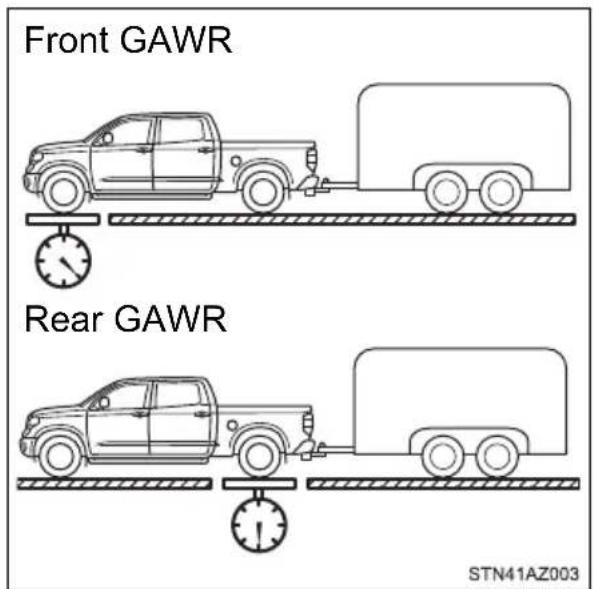
■TWR (Trailer Weight Rating)
The maximum allowable gross trailer weight. The gross trailer weight is the sum of the trailer weight and the weight of the cargo in the trailer.
TWR is calculated assuming base vehicle with one driver, one front passenger, towing package (if available), hitch and hitch systems (if required).
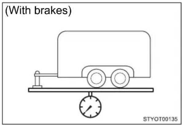
Additional optional equipment, passengers and cargo in the vehicle will reduce the trailer weight rating so as not to exceed GCWR, GVWR and GAWR.
If the gross trailer weight exceeds 3000 lb. (1360 kg), it is recommended to use a trailer with 2 or more axles.
■ Unbraked TWR (Unbraked Trailer Weight Rating)
The trailer weight rating for towing a trailer without a trailer service brake system.
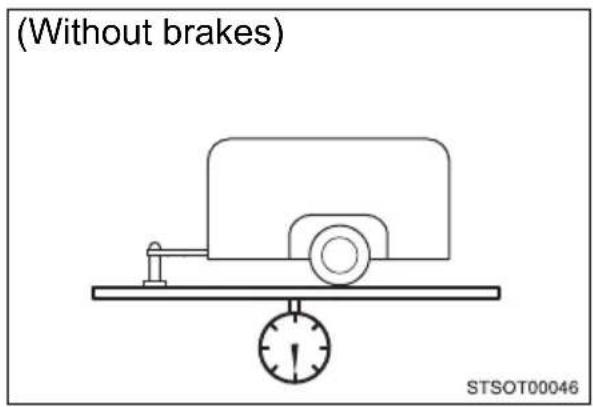
■Tongue Weight
The load placed on the trailer hitch ball. ( P. 205)
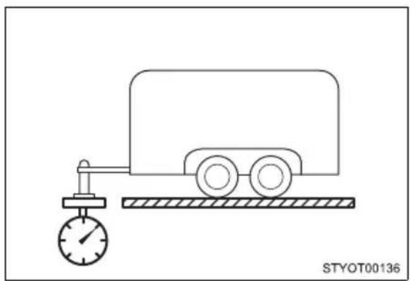
natural_image
Simple line drawing of a fuel truck with a pressure gauge and horizontal bar (no text or symbols)Kingpin Weight
The load placed on the 5th wheel mount or the gooseneck ball. (→P. 206)
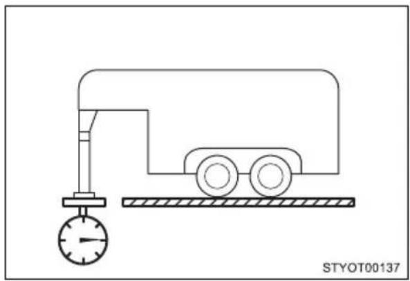
natural_image
Simple line drawing of a mechanical device with a dial indicator and two wheels on a conveyor (no text or symbols)Weight limits
●The gross trailer weight must never exceed the TWR described in the table. (→P. 201)
●The gross combination weight must never exceed the GCWR described in the table. (→P. 201)
●The gross vehicle weight must never exceed the GVWR indicated on the Certification Label.
●The gross axle weight on each axle must never exceed the GAWR indicated on the Certification Label.
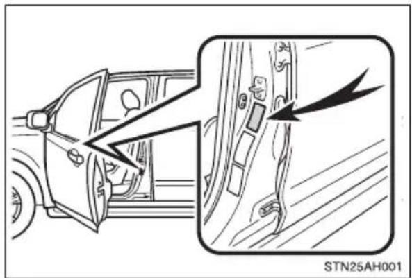
- If the gross trailer weight is over the unbraked TWR, trailer service brakes are required.
- If the gross trailer weight is over 2000 lb. (907 kg), a sway control device with sufficient capacity is required.
- If the gross trailer weight is over 5000 lb. (2268 kg), a weight distributing hitch with sufficient capacity is required.
GCWR, TWR, Unbraked TWR, Fifth wheel and Gooseneck towing TWR
Confirm that the gross trailer weight, gross combination weight, gross vehicle weight, gross axle weight and tongue weight are all within the limits.
■GCWR ^*5 and TWR ^*5
▶ Double Cab models
| Model code*1 | Engine | Driving system | Bed type | GCWR TWR | |
| USK51L-CRTSKA | 3UR-FE engine | 2WD | Standard | 14000 lb. (6350 kg)*2 | 8300 lb. (3760 kg)*2 |
| 16000 lb. (7255 kg)*3 | 10200 lb. (4625 kg)*3 | ||||
| 16000 lb. (7255 kg)*4 | 10100 lb. (4580 kg)*4 | ||||
| USK51L-CRTLKA | 14000 lb. (6350 kg)*2 | 8200 lb. (3715 kg)*2 | |||
| 16000 lb. (7255 kg)*3 | 10200 lb. (4625 kg)*3 | ||||
| 16000 lb. (7255 kg)*4 | 10100 lb. (4580 kg)*4 | ||||
| USK52L-CHTSKA | Long | 14000 lb. (6350 kg)*2 | 8100 lb. (3670 kg)*2 | ||
| 16000 lb. (7255 kg)*3 | 10100 lb. (4580 kg)*3 | ||||
| 16000 lb. (7255 kg)*4 | 10000 lb. (4535 kg)*4 |
*5: These models meet the tow-vehicle trailering requirement of SAE International per SAE J2807.
| Model code*1 | Engine | Driving system | Bed type | GCWR TWR | |
| USK56L-CRTSKA | 3UR-FE engine | 4WD | Standard | 14000 lb. (6350 kg)*2 | 8000 lb. (3625 kg)*2 |
| 16000 lb. (7255 kg)*3 | 9900 lb. (4490 kg)*3 | ||||
| 15820 lb. (7175 kg)*4 | 9600 lb. (4355 kg)*4 | ||||
| USK56L-CRTLKA | 14000 lb. (6350 kg)*2 | 7900 lb. (3580 kg)*2 | |||
| 16000 lb. (7255 kg)*3 | 9900 lb. (4490 kg)*3 | ||||
| 15310 lb. (6945 kg)*4 | 9100 lb. (4125 kg)*4 | ||||
| USK57L-CHTSKA | Long | 14000 lb. (6350 kg)*2 | 7800 lb. (3535 kg)*2 | ||
| 16000 lb. (7255 kg)*3 | 9800 lb. (4445 kg)*3 | ||||
| 15620 lb. (7085 kg)*4 | 9300 lb. (4215 kg)*4 |
^*1 : The model code is indicated on the Certification Label. ( P. 541)
*2: Vehicles without towing package
*3: Vehicles with towing package
*4: Vehicles with towing package and large fuel tank
▶ CrewMax models
| Model code*1 | Engine | Driving system | Bed type | GCWR TWR | |
| USK51L-PSTSKA | 3UR-FE engine | 2WD | Short | 14000 lb. (6350 kg)*2 | 8100 lb. (3670 kg)*2 |
| 16000 lb. (7255 kg)*3 | 10100 lb. (4580 kg)*3 | ||||
| 15890 lb. (7205 kg)*4 | 9900 lb. (4490 kg)*4 | ||||
| USK51L-PSTLKA | 14000 lb. (6350 kg)*2 | 8000 lb. (3625 kg)*2 | |||
| 16000 lb. (7255 kg)*3 | 10000 lb. (4535 kg)*3 | ||||
| 15530 lb. (7045 kg)*4 | 9400 lb. (4260 kg)*4 | ||||
| USK51L-PSTZKA | 14000 lb. (6350 kg)*2 | 8000 lb. (3625 kg)*2 | |||
| 16000 lb. (7255 kg)*3 | 10000 lb. (4535 kg)*3 | ||||
| 15520 lb. (7040 kg)*4 | 9400 lb. (4260 kg)*4 | ||||
| USK56L-PSTSKA | 4WD | 14000 lb. (6350 kg)*2 | 7800 lb. (3535 kg)*2 | ||
| 16000 lb. (7255 kg)*3 | 9800 lb. (4445 kg)*3 | ||||
| 15510 lb. (7035 kg)*4 | 9200 lb. (4170 kg)*4 | ||||
| USK56L-PSTLKA | 14000 lb. (6350 kg)*2 | 7800 lb. (3535 kg)*2 | |||
| 16000 lb. (7255 kg)*3 | 9700 lb. (4400 kg)*3 | ||||
| 15140 lb. (6865 kg)*4 | 8800 lb. (3990 kg)*4 | ||||
| USK56L-PSTZKA | 3UR-FE engine | 4WD Short | 14000 lb. (6350 kg)*2 | 7800 lb. (3535 kg)*2 | |
| 16000 lb. (7255 kg)*3 | 9800 lb. (4445 kg)*3 | ||||
| 15160 lb. (6875 kg)*4 | 8800 lb. (3990 kg)*4 | ||||
*1: The model code is indicated on the Certification Label. (→P. 541)
*2: Vehicles without towing package
*3: Vehicles with towing package
*4: Vehicles with towing package and large fuel tank
■Unbraked TWR* 5
1000 lb. (453 kg)
*5: These models meet the tow-vehicle trailering requirement of SAE International per SAE J2807.
Trailer Tongue Weight and Trailer Kingpin Weight
●A recommended tongue weight or kingpin weight varies in accordance with the types of trailers or towing as described below.
●To ensure the recommended values shown below, the trailer must be loaded by referring to the following instructions.
1. Conventional Towing
The gross trailer weight should be distributed so that the tongue weight is 9% to 11%. (Tongue Weight/Gross trailer weight x 100 = 9% to 11%)
① Gross trailer weight
② Tongue Weight
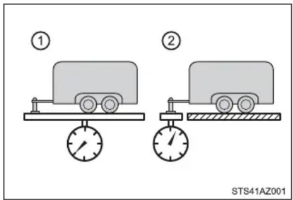
If using a weight distributing hitch when towing, return the front axle to the same weight as before the trailer connection.
If front axle weight cannot be measured directly, measure the front fender height above the front axle before connection. Adjust weight distributing hitch torque until front fender is returned to the same height as before connection.
Do not reduce front fender height below original measurement.
The gross trailer weight, gross axle weight and tongue weight can be measured with platform scales found at a highway weighing station, building supply company, trucking company, junk yard, etc.
2.Fifth wheel Towing or Gooseneck Towing
The gross trailer weight should be distributed so that the kingpin weight is 14% to 16%. (Kingpin weight/Gross trailer weight x 100 = 14% to 16%)
① Gross trailer weight
② Kingpin weight
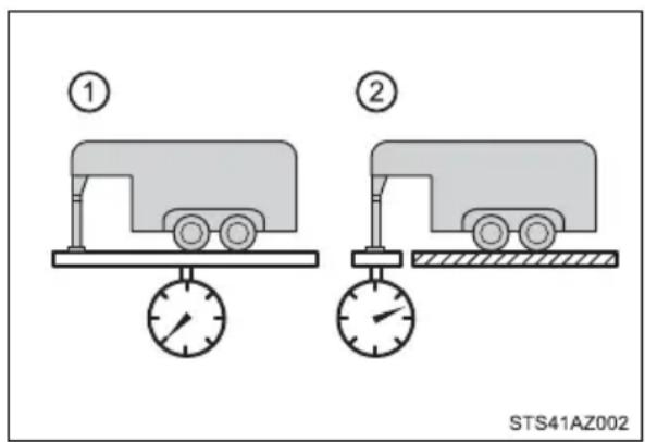
The gross trailer weight and kingpin weight can be measured with platform scales found at a highway weighing station, building supply company, trucking company, junk yard, etc.
CrewMax models: Current fifth wheel trailer designs are not compatible with short bed.
Hitch
Trailer hitch assemblies have different weight capacities. Toyota recommends the use of Toyota hitch/bracket for your vehicle. For details, contact your Toyota dealer.
- If you wish to install a trailer hitch, contact your Toyota dealer.
- Use only a hitch that conforms to the gross trailer weight requirement of your vehicle.
●Follow the directions supplied by the hitch manufacturer.
● Lubricate the hitch ball and kingpin with a light coating of grease. - Remove the hitch ball whenever you are not towing a trailer. Remove the trailer hitch if you do not need it. After removing the hitch, seal any mounting hole in the vehicle body to prevent entry of any substances into the vehicle.
Bumper towing (vehicles with steel bumper only)
The rear bumper of your vehicle is equipped with a hole to install a trailer ball. If you have any questions, contact your Toyota dealer.
The gross trailer weight (trailer weight plus cargo weight) when towing with the bumper must never exceed the TWR ( P. 201) or 5000 lb. (2268 kg) whichever is lower.
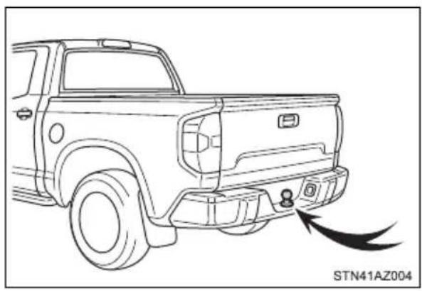
natural_image
Line drawing of a pickup truck's side profile with exhaust pipe and brand mark (STN41AZ004), no text or symbols on the vehicle itself.Selecting trailer ball
Use the correct trailer ball for your application.
① Trailer ball load rating
Matches or exceeds the gross trailer weight rating of the trailer.
② Ball diameter
Matches the size of the trailer coupler. Most couplers are stamped with the required trailer ball size.
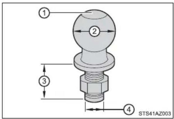
| Trailer class | IV II and III I | ||
| Typical trailer ball size | 2 5/16 in. | 2 in. | 1 7/8 in. |
③ Shank length
Protrudes beyond the bottom of the lock washer and nut by at least 2 threads.
④ Shank diameter
Matches the ball mount hole diameter size.
Positions for towing hitch receiver
① Hitch receiver pin hole position: 46.4 in. (1179 mm)
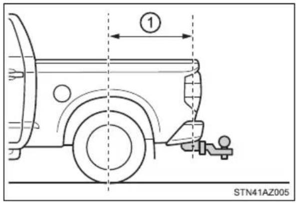
Connecting trailer lights
Use the wire harness stored in the rear end of the vehicle.
The tow lighting system is designed for 64 watts/5 amps of electrical current per side (right and left) for the trailer brake/turn light functions.
Please contact your Toyota dealer with any questions or concerns.
▶ Vehicles without towing package
▶ Vehicles with towing package
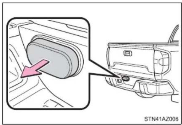
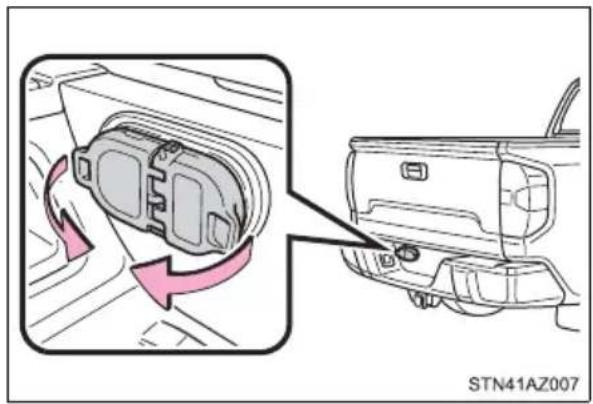
natural_image
Diagram showing a car interior component with directional arrows indicating rotation, no text or symbols present■ Service connector for towing brake controllers (vehicles without an installed trailer brake controller)
Your vehicle is equipped with a service connector for supplemental trailer brake controllers.
Please consult your dealer on how to access the service connector.
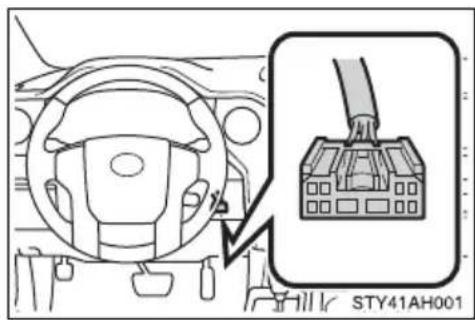
Trailer towing tips
Your vehicle will handle differently when towing a trailer. To help avoid an accident, death or serious injury, keep the following in mind when towing:
● Speed limits for towing a trailer vary by state or province. Do not exceed the posted towing speed limit.
- Toyota recommends that the vehicle-trailer speed limit is 65 mph (104 km/h) on a flat, straight, dry road. Do not exceed this limit, the posted towing speed limit or the speed limit for your trailer as set forth in your trailer owner's manual, whichever is lowest. Instability of the towing vehicle-trailer combination (trailer sway) increases as speed increases. Exceeding speed limits may cause loss of control.
- Before starting out, check the trailer lights, tires and the vehicle-trailer connections. Recheck after driving a short distance.
● Practice turning, stopping and reversing with the trailer attached in an area away from traffic until you become accustomed to the feel of the vehicle-trailer combination.
- Reversing with a trailer attached is difficult and requires practice. Grip the bottom of the steering wheel and move your hand to the left to move the trailer to the left. Move your hand to the right to move the trailer to the right. (This is generally opposite to reversing without a trailer attached.) Avoid sharp or prolonged turning. Have someone guide you when reversing to reduce the risk of an accident.
- As stopping distance is increased when towing a trailer, vehicle-to-vehicle distance should be increased. For each 10 mph (16 km/h) of speed, allow at least one vehicle and trailer length.
- Avoid sudden braking as you may skid, resulting in the trailer jack-knifing and a loss of vehicle control. This is especially true on wet or slippery surfaces.
●Avoid jerky starts or sudden acceleration. - Avoid jerky steering and sharp turns, and slow down before making a turn.
● Note that when making a turn, the trailer wheels will be closer than the vehicle wheels to the inside of the turn. Compensate by making a wider than normal turning radius. - Slow down before making a turn, in crosswinds, on wet or slippery surfaces, etc.
Increasing vehicle speed can destabilize the trailer.
●Take care when passing other vehicles. Passing requires considerable distance. After passing a vehicle, do not forget the length of your trailer, and be sure you have plenty of room before changing lanes.
● To maintain engine braking efficiency and charging system performance when using engine braking, do not use the transmission in D.
Transmission shift range position must be in 4 in the S mode.
●Instability happens more frequently when descending steep or long downhill grades. Before descending, slow down and downshift. Do not make sudden downshifts while descending steep or long downhill grades.
- Avoid holding the brake pedal down too long or applying the brakes too frequently. This could cause the brakes to overheat and result in reduced braking efficiency.
- Due to the added load of the trailer, your vehicle's engine may overheat on hot days (at temperatures over 85^ [30°C]) when driving up a long or steep grade. If the engine coolant temperature gauge indicates overheating, immediately turn off the air conditioning (if in use), pull your vehicle off the road and stop in a safe spot.
(→P. 529)
- Always place wheel blocks under both the vehicle's and the trailer's wheels when parking. Apply the parking brake firmly, and put the transmission in P. Avoid parking on a slope, but if unavoidable, do so only after performing the following:
1 Apply the brakes and keep them applied.
2 Have someone place wheel blocks under both the vehicle's and trailer's wheels.
3 When the wheel blocks are in place, release the brakes slowly until the blocks absorb the load.
4 Apply the parking brake firmly.
5 Shift into P and turn off the engine.
●When restarting after parking on a slope:
1 With the transmission in P, start the engine. Be sure to keep the brake pedal pressed.
2 Shift into D or R (if reversing).
3 Release the parking brake and brake pedal, and slowly pull or back away from the wheel blocks. Stop and apply the brakes.
4 Have someone retrieve the blocks.
■Trailer brake controller
→P. 327
■ Matching trailer ball height to trailer coupler height
No matter which class of tow hitch applies, for a more safe trailer hookup, the trailer ball setup must be the proper height for the coupler on the trailer.
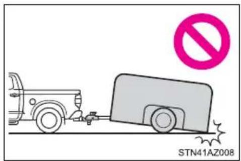
① Coupler
② Trailer ball
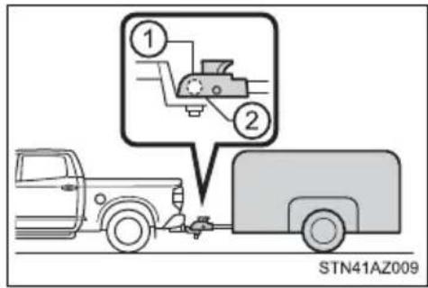
Before towing
Check that the following conditions are met:
- Ensure that your vehicle's tires are properly inflated. (→P. 548)
- Trailer tires are inflated according to the trailer manufacturer's recommendation.
● All trailer lights work as required by law.
●All lights work each time you connect them.
● The trailer ball is set at the proper height for the coupler on the trailer.
●The trailer is level when it is hitched. Do not drive if the trailer is not level, and check for improper tongue weight, overloading, worn suspension, or other possible causes.
●The trailer cargo is securely loaded.
●The rear view mirrors conform to all applicable federal, state/provincial or local regulations. If they do not, install rear view mirrors appropriate for towing purposes.
● Depress TOW/HAUL button (if equipped). (→P. 228)
● The manual headlight leveling dial is correctly adjusted. (→P. 236)
■Break-in schedule
If your vehicle is new or equipped with any new power train components (such as an engine, transmission, differential or wheel bearing), Toyota recommends that you do not tow a trailer until the vehicle has been driven for over 500 miles (800 km).
After the vehicle has been driven for over 500 miles (800 km), you can start towing. However, for the next 500 miles (800 km), drive the vehicle at a speed of less than 50 mph (80 km/h) when towing a trailer, and avoid full throttle acceleration.
Maintenance
- If you tow a trailer, your vehicle will require more frequent maintenance due to the additional load. (See “Owner’s Warranty Information Booklet” or “Scheduled Maintenance Guide”/“Owner’s Manual Supplement”.)
- Retighten the fixing bolts of the towing ball and bracket after approximately 600 miles (1000 km) of trailer towing.
If trailer sway occurs
One or more factors (crosswinds, passing vehicles, rough roads, etc.) can adversely affect handling of your vehicle and trailer, causing instability.
- If trailer swaying occurs:
- Firmly grip the steering wheel. Steer straight ahead.
Do not try to control trailer swaying by turning the steering wheel. - Begin releasing the accelerator pedal immediately but very gradually to reduce speed.
Do not increase speed. Do not apply vehicle brakes.
If you make no extreme correction with the steering or brakes, your vehicle and trailer should stabilize. (if enabled, Trailer Sway Control can also help to stabilize the vehicle and trailer.)
●After the trailer swaying has stopped:
- Stop in a safe place. Get all occupants out of the vehicle.
- Check the tires of the vehicle and the trailer.
- Check the load in the trailer.
Make sure the load has not shifted.
Make sure the tongue weight is appropriate, if possible.
- Check the load in the vehicle.
Make sure the vehicle is not overloaded after occupants get in.
If you cannot find any problems, the speed at which trailer swaying occurred is beyond the limit of your particular vehicle-trailer combination.
Drive at a lower speed to prevent instability. Remember that swaying of the towing vehicle-trailer increases as speed increases.

WARNING
■Trailer towing precautions
To tow a trailer safely, use extreme care and drive the vehicle in accordance with the trailer's characteristics and operating conditions. Failure to do so could cause an accident resulting in death or serious injury. Vehicle stability and braking performance are affected by trailer stability, brake setting and performance, and the hitch. Your vehicle will handle differently when towing a trailer.
■To avoid accident or injury
●Do not exceed the TWR, unbraked TWR, GCWR, GVWR or GAWR.
- If the gross trailer weight is over 2000 lb. (907 kg), a sway control device with sufficient capacity is required.
- If the gross trailer weight is over 5000 lb. (2268 kg), a weight distributing hitch with sufficient capacity is required.
- Adjust the tongue weight within the appropriate range. Place heavier loads as close to the trailer axle as possible.
- Do not exceed 65 mph (104 km/h), the posted towing speed limit or the speed limit for your trailer as set forth in your trailer owner's manual whichever is lowest. Slow down sufficiently before making a turn, in cross-winds, on wet or slippery surface, etc., to help avoid an accident. If you experience a vehicle-trailer instability from reducing a certain speed, slow down and make sure you keep your vehicle speed under the speed which you experience the instability.
●Do not make jerky, abrupt or sharp turns.
- Do not apply the brakes suddenly as you may skid, resulting in jackknifing and loss of vehicle control. This is especially true on wet or slippery surfaces.
- Do not exceed the trailer hitch assembly weight, gross vehicle weight, gross axle weight and trailer tongue weight capacities.
- Do not use cruise control when towing.
● Slow down and downshift before descending steep or long downhill grades. Do not make sudden downshifts while descending steep or long downhill grades.
● Vehicle-trailer instability is more likely on steep long downhills. Before descending steep or long downhill grades, slow down and downshift. Do not make sudden downshifts when descending steep or long downhill grades. Avoid holding the brake pedal down too long or applying the brakes too frequently. This could cause the brakes to overheat and result in reduced braking efficiency.
- Do not tow a trailer when the temporary spare tire is installed on your vehicle.
of

WARNING
Hitch
Trailer hitch assemblies have different weight capacities established by the hitch manufacturer. Even though the vehicle may be physically capable of towing a higher weight, the operator must determine the maximum weight rating of the particular hitch assembly and never exceed the maximum weight rating specified for the trailer-hitch. Exceeding the maximum weight rating set by the trailer-hitch manufacturer can cause an accident resulting in death or serious personal injuries.
■When towing a trailer
Toyota recommends trailers with brakes that conform to any applicable federal and state/provincial regulations.
- If the gross trailer weight exceeds unbraked TWR, trailer brakes are required. Toyota recommends trailers with brakes that conform to all applicable federal and state/provincial regulations.
- Never tap into your vehicle's hydraulic system, as this will lower the vehicle's braking effectiveness.
● Never tow a trailer without using a safety chain securely attached to both the trailer and the vehicle. If damage occurs to the coupling unit or hitch ball, there is danger of the trailer wandering into another lane.

NOTICE
■When installing a trailer hitch
Use only the position recommended by your Toyota dealer. Do not install the trailer hitch on the bumper; this may cause body damage.
■Do not directly splice trailer lights
Do not directly splice trailer lights. Directly splicing trailer lights may damage your vehicle's electrical system and cause a malfunction.
■When towing a fifth wheel trailer
Be careful not to hit the cabin or bed with the trailer while making a sharp turn.
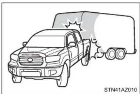
natural_image
Line drawing of a pickup truck with a moving truck emitting smoke (no text or symbols)Dinghy towing
Your vehicle is not designed to be dinghy towed (with 4 wheels on the ground) behind a motor home.
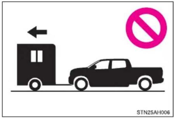

NOTICE
■To avoid serious damage to your vehicle
Do not tow your vehicle with the four wheels on the ground.
Engine (ignition) switch (vehicles without a smart key system)
Starting the engine
1 Check that the parking brake is set.
2 Check that the shift lever is set in P.
3 Firmly depress the brake pedal.
4 Turn the engine switch to the "START" position to start the engine.
Changing the engine switch positions
① OFF ("LOCK" position) The steering wheel is locked and the key can be removed. (The key can be removed only when the shift lever is in P.)
② ACC (“ACC” position) Some electrical components such as the audio system can be used.
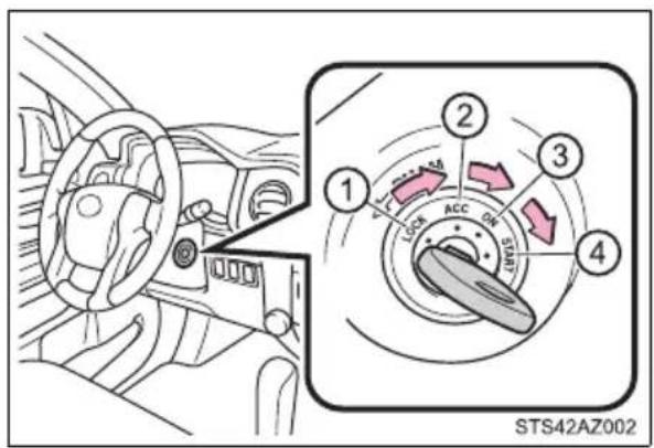
③ ON ("ON" position) All electrical components can be used.
④ START ("START" position) For starting the engine.
■Turning the key from ACC to OFF
1 Shift the shift lever to P.
2 Push in the key and turn it to OFF.
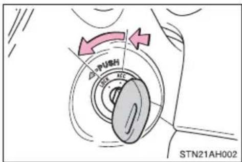
If the engine does not start
The engine immobilizer system may not have been deactivated. (→P. 85) Contact your Toyota dealer.
■When the steering lock cannot be released
When starting the engine, the engine switch may seem stuck in the free it, turn the key while turning the steering wheel slightly left and right.
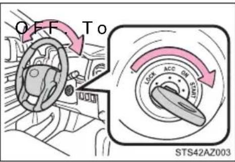
■Key reminder function
A buzzer sounds if the driver's door is opened while the engine switch is in ACC or OFF to remind you to remove the key.

WARNING
■When starting the engine
Always start the engine while sitting in the driver's seat. Do not depress the accelerator pedal while starting the engine under any circumstances. Doing so may cause an accident resulting in death or serious injury.
■Caution while driving
Do not turn the engine switch to OFF while driving. If, in an emergency, you must turn the engine off while the vehicle is moving, turn the engine switch only to ACC to stop the engine. An accident may result if the engine is stopped while driving. (→P. 475)

NOTICE
■To prevent battery discharge
Do not leave the engine switch in ACC or ON for long periods of time without the engine running.
When starting the engine
- Do not crank the engine for more than 30 seconds at a time. This may overheat the starter and wiring system.
- Do not race a cold engine.
- If the engine becomes difficult to start or stalls frequently, have your vehicle checked by your Toyota dealer immediately.
Engine (ignition) switch (vehicles with a smart key system)
Performing the following operations when carrying the electronic key on your person starts the engine or changes engine switch modes.
Starting the engine
1 Check that the parking brake is set.
2 Check that the shift lever is in P.
3 Firmly depress the brake pedal.

and a message will be displayed on the multi-information display.
If it is not displayed, the engine cannot be started.
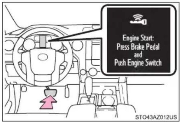
4 Press the engine switch shortly and firmly.
When operating the engine switch, one short, firm press is enough. It is not necessary to press and hold the switch.
The engine will crank until it starts or for up to 30 seconds, whichever is less.
Continue depressing the brake pedal until the engine is completely started.
The engine can be started from any engine switch mode.
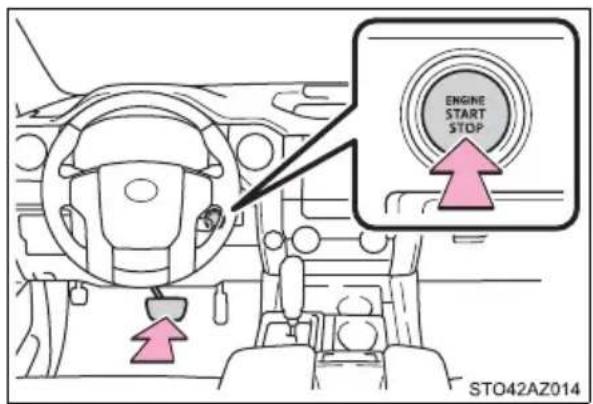
Stopping the engine
1 Stop the vehicle.
2 Set the parking brake ( P. 233), and shift the shift lever to P.
3 Press the engine switch.
4 Release the brake pedal and check that the display on the instrument cluster is off.
Changing engine switch modes
Modes can be changed by pressing the engine switch with brake pedal released. (The mode changes each time the switch is pressed.)
① OFF*
The emergency flashers can be used.
② ACC
Some electrical components such as the audio system can be used.
"ACCESSORY" will be displayed on the multi-information display.
③ ON
All electrical components can be used.
"IGNITION ON" will be displayed on the multi-information display.
*: If the shift lever is in a position other than P when turning off the engine, the engine switch will be turned to ACC, not to off.
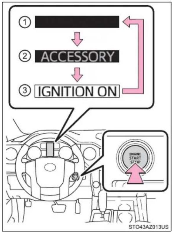
flowchart
graph TD
    A["①"] --> B["② ACCESSORY"]
    B --> C["③ IGNITION ON"]
    D["Engine Start Stop"] --> E["StO43AZ013US"]
When stopping the engine with the shift lever in a position other than P
If the engine is stopped with the shift lever in a position other than P, the engine switch will not be turned off but instead be turned to ACC. Perform the following procedure to turn the switch off:
1 Check that the parking brake is set.
2 Shift the shift lever to P.
3 Check that "Turn Power OFF" is displayed on the multi-information display and then press the engine switch once.
4 Check that "Turn Power OFF" on the multi-information display is off.
■Auto power off function
If the vehicle is left in ACC for more than 20 minutes or ON (the engine is not running) for more than an hour with the shift lever in P, the engine switch will automatically turn off. However, this function cannot entirely prevent battery discharge. Do not leave the vehicle with the engine switch in ACC or ON for long periods of time when the engine is not running.
■ Automatic engine shut off feature (except for New Caledonia)
● The vehicle is equipped with a feature that automatically shuts off the engine when the shift lever is in P with the engine running for an extended period.
● The engine will automatically shut off after approximately 1 hour if it has been left running while the shift lever is in P.
● The timer for the automatic engine shut off feature will reset if the brake pedal is depressed or if the shift lever is in a position other than P.
After the vehicle is parked, if the door is locked with the door lock switch (→P. 130) from the inside or the mechanical key (→P. 523) from the outside, the automatic engine shut off feature will be disabled. The timer for the automatic engine shut off feature will be re-enabled if the driver's door is opened.
Electronic key battery depletion
→P. 124
■Conditions affecting operation
→P. 142
Note for the entry function
→P. 142
If the engine does not start
● The engine immobilizer system may not have been deactivated. (→P. 85) Contact your Toyota dealer.
- Check that the shift lever is securely set in P. The engine may not start if the shift lever is displaced out of P. "Shift to P Position" will be displayed on the multi-information display.
Steering lock
After turning the engine switch off and opening and closing the doors, the steering wheel will be locked due to the steering lock function. Operating the engine switch again automatically cancels the steering lock.
■When the steering lock cannot be released
A message will be displayed on the multi-information display.
Check that the shift lever is in P. Press the engine switch while turning the steering wheel left and right.
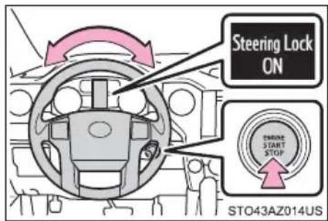
■Steering lock motor overheating prevention
To prevent the steering lock motor from overheating, operation of the motor may be suspended if the engine is turned on and off repeatedly in a short period of time. In this case, refrain from running the engine. After about 10 seconds, the steering lock motor will resume functioning.
When "Smart Entry & Start System Check" is displayed on the multi-information display
The system may be malfunctioning. Have the vehicle inspected by your Toyota dealer immediately.
If the electronic key battery is depleted
→P. 451
Operation of the engine switch
- If the switch is not pressed shortly and firmly, the engine switch mode may not change or the engine may not start.
- If attempting to restart the engine immediately after turning the engine switch off, the engine may not start in some cases. After turning the engine switch off, please wait a few seconds before restarting the engine.
If the smart key system has been deactivated by a customized setting →P. 523

WARNING
■When starting the engine
Always start the engine while sitting in the driver's seat. Do not depress the accelerator pedal while starting the engine under any circumstances. Doing so may cause an accident resulting in death or serious injury.
■Caution while driving
If engine failure occurs while the vehicle is moving, do not lock or open the doors until the vehicle reaches a safe and complete stop. Otherwise, the steering lock function will activate and this may lead to an accident, resulting in death or serious injury.
■Stopping the engine in an emergency
If you want to stop the engine in an emergency while driving the vehicle, press and hold the engine switch for more than 2 seconds, or press it briefly 3 times or more in succession. ( P. 475)
However, do not touch the engine switch while driving except in an emergency. Turning the engine off while driving will not cause loss of steering or braking control, however, power assist to the steering will be lost. This will make it more difficult to steer smoothly, so you should pull over and stop the vehicle as soon as it is safe to do so.
■When parking (except for New Caledonia)
Exhaust gases include harmful carbon monoxide (CO), which is colorless and odorless. Observe the following precautions.
Failure to do so may cause exhaust gases to enter the vehicle and may lead to an accident caused by light-headedness, or may lead to death or a serious health hazard.
- If the vehicle is in a poorly ventilated area or a closed area, such as a garage, stop the engine.
- Do not leave the vehicle with the engine running for a long time. If such a situation cannot be avoided, park the vehicle in an open space and ensure that exhaust fumes do not enter the vehicle interior.
- Do not leave the engine running in an area with snow build-up, or where it is snowing. If snowbanks build up around the vehicle while the engine is running, exhaust gases may collect and enter the vehicle.

NOTICE
■To prevent battery discharge
- Do not leave the engine switch in ACC or ON for long periods of time without the engine running.
- If “ACCESSORY” or “IGNITION ON” is displayed on the multi-information display while the engine is not running, the engine switch is not off. Exit the vehicle after turning the engine switch off.
- Do not stop the engine when the shift lever is in a position other than P. If the engine is stopped in another shift lever position, the engine switch will not be turned off but instead be turned to ACC. If the vehicle is left in ACC, battery discharge may occur.
When starting the engine
- Do not race a cold engine.
- If the engine becomes difficult to start or stalls frequently, have your vehicle checked by your Toyota dealer immediately.
■ Symptoms indicating a malfunction with the engine switch
If the engine switch seems to be operating somewhat differently than usual, such as the switch sticking slightly, there may be a malfunction. Contact your Toyota dealer immediately.
Automatic transmission
Shifting the shift lever
▶ Floor shift type
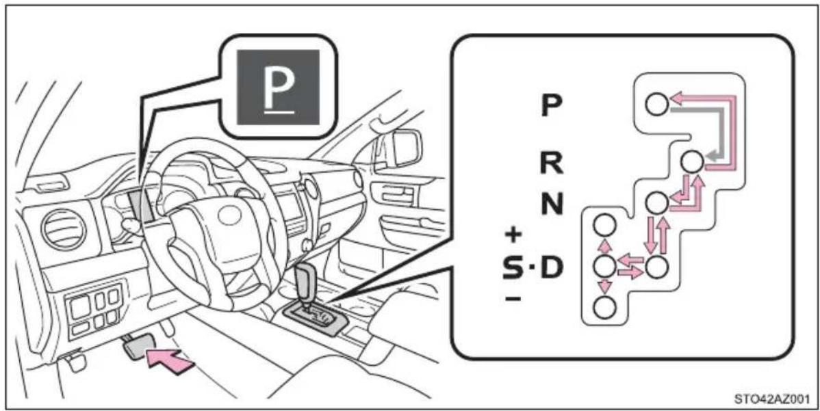
While the engine switch is in ON, move the shift lever with the brake pedal depressed.
When shifting the shift lever between P and D, make sure that the vehicle is completely stopped.
Column shift type
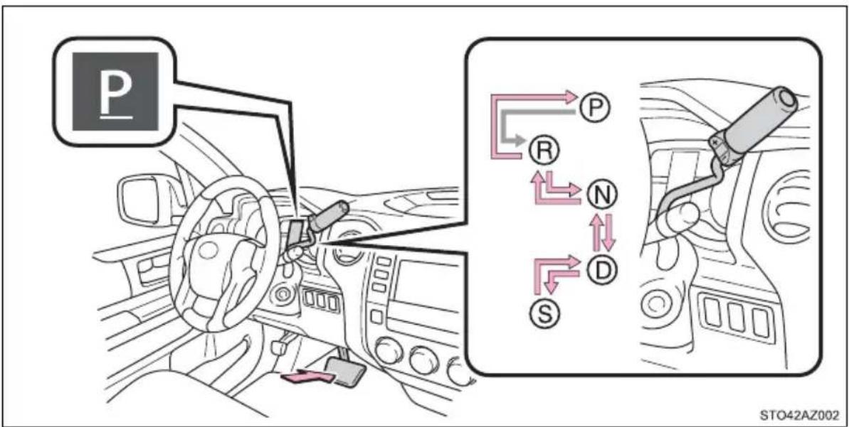
While the engine switch is in ON, move the shift lever with the brake pedal depressed.
When shifting the shift lever between P and D, make sure that the vehicle is completely stopped.
Shift position purpose
| Shift position Function | |
| P Parking the vehicle/starting the engine | |
| R Reversing | |
| N | Neutral(Condition in which the power is not transmitted) |
| D Normal driving* | 1 |
| S S mode driving* | ^2 ( P. 227) |
*1: To improve fuel efficiency and reduce noises, set the shift lever in the D position for normal driving.
*2: Selecting shift ranges using S mode restricts the upper limit of the possible gear ranges, controls engine braking forces, and prevents unnecessary upshifting.
Selecting shift ranges in the S position
To enter S mode, shift the shift lever to S. Shift ranges can be selected by operating the shift lever, allowing you to drive in the shift range of your choosing. The shift range can be selected by the shift lever.
▶ Floor shift type ▶ Column shift type
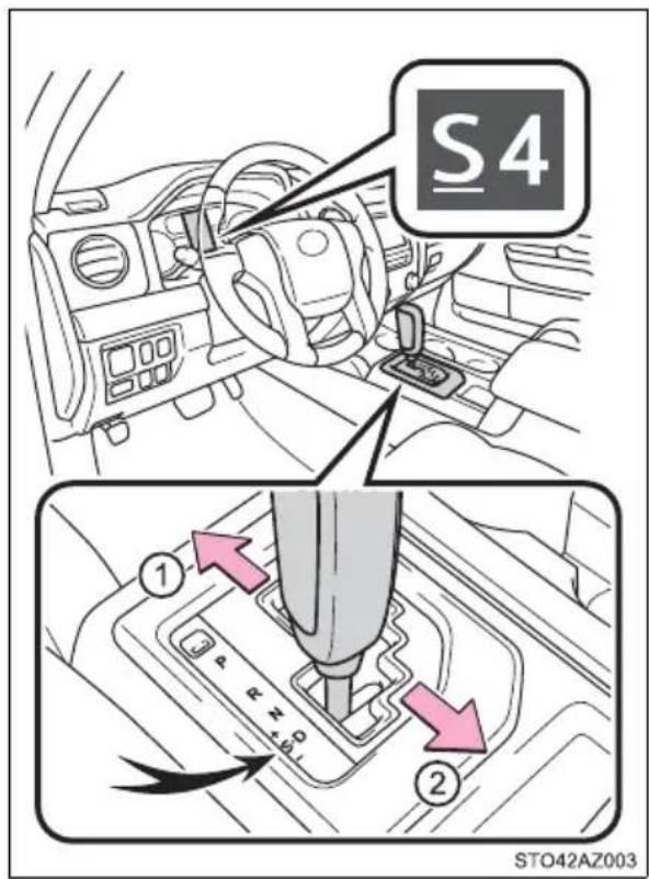
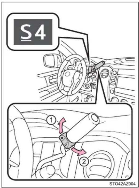
① Upshifting
② Downshifting
The selected shift range, from 1 to 6, will be displayed in the meter.
The initial shift range in S mode is set automatically to 5 or 4 according to vehicle speed. However, the initial shift range may be set to 3 or 2 if the AI-SHIFT ( P. 229) has operated while the shift lever was in the D position.
■Shift ranges and their functions
●Automatically selecting gears between 1 and 6 according to vehicle speed and driving conditions.
●You can choose from 6 levels of accelerating force and engine braking force.
●A lower shift range will provide greater accelerating force and engine braking force than a higher shift range, and the engine revolutions will also increase.
TOW/HAUL switch (vehicles with towing package)
Use TOW/HAUL mode when pulling a trailer or hauling a heavy load. Press the TOW/HAUL switch. The indicator will come on.
Press the switch once more to cancel the mode.
▶ Floor shift type ▶ Column shift type
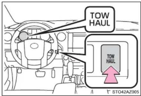
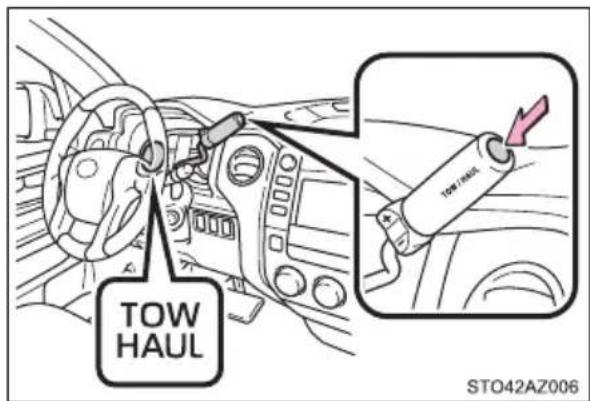
AI-SHIFT
AI-SHIFT automatically selects the suitable gear according to the driver performance and driving conditions.
AI-SHIFT automatically operates when the shift lever is in the D position. (Shifting the shift lever to the S position cancels the function.)
■When driving with cruise control activated (if equipped)
Even when performing the following actions with the intent of enabling engine braking, engine braking will not activate while driving in S mode and down-shifting to 5 or 4 because cruise control will not be canceled. ( P. 280, 294)
Shift lock system
The shift lock system is a system to prevent accidental operation of the shift lever in starting.
The shift lever can be shifted from P only when the engine switch is in ON and the brake pedal is being depressed.
If the shift lever cannot be shifted from P
First, check whether the brake pedal is being depressed.
If the shift lever cannot be shifted with your foot on the brake pedal, there may be a problem with the shift lock system. Have the vehicle inspected by your Toyota dealer immediately.
The following steps may be used as an emergency measure to ensure that the shift lever can be shifted.
Releasing the shift lock:
1 Set the parking brake.
2 Turn the engine switch to OFF.
3 Depress the brake pedal.
4 Pry the cover up with a flathead screwdriver or equivalent tool. To prevent damage to the cover, cover the tip of the screwdriver with a rag.
▶ Floor shift type ▶ Column-shift type
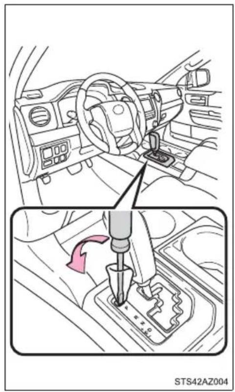
natural_image
Interior view of a car showing the steering wheel and gear shift mechanism (no text or symbols visible)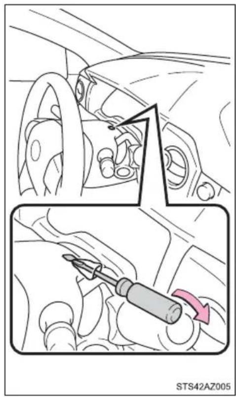
5 Press the shift lock override button. The shift lever can be shifted while the button is pressed.
▶ Floor shift type ▶ Column-shift type
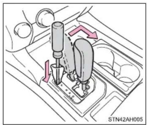
natural_image
Diagram of a car gear shift mechanism with directional arrows indicating motion (no text or symbols)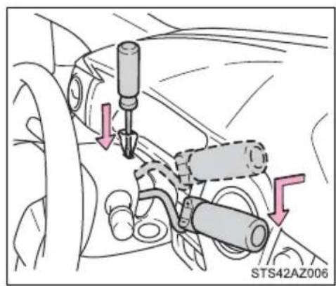
natural_image
Mechanical assembly diagram showing a screwdriver inserted into a car's head, with no visible text or symbolsIf the “S” indicator does not come on even after shifting the shift lever to S
This may indicate a malfunction in the automatic transmission system. Have the vehicle inspected by your Toyota dealer, immediately.
(In this situation, the transmission will operate in the same manner as when the shift lever is in D.)
■Downshifting restrictions warning buzzer (S mode)
To help ensure safety and driving performance, downshifting operation may sometimes be restricted. In some circumstances, downshifting may not be possible even when the shift lever is operated. (A buzzer will sound twice.)
■Transmission protection function
If the tires spin continually when the vehicle becomes stuck in mud, dirt or snow, the automatic transmission temperature may become too high and cause damage.
To avoid the damaging the automatic transmission, the system may temporarily lock the gear in 1st.
If the automatic transmission temperature falls, the gear locking is canceled and returns the automatic transmission to the normal operation.

WARNING
■When driving on slippery road surfaces
Do not accelerate or shift gears suddenly.
Sudden changes in engine braking may cause the vehicle to spin or skid, resulting in an accident.
■To prevent an accident when releasing the shift lock
Before pressing the shift lock override button, make sure to set the parking brake and depress the brake pedal.
If the accelerator pedal is accidentally depressed instead of the brake pedal when the shift lock override button is pressed and the shift lever is shifted out of P, the vehicle may suddenly start, possibly leading to an accident resulting in death or serious injury.
Turn signal lever
Operating instructions
① Right turn
② Lane change to the right (move the lever partway and release it)
The right hand signals will flash 3 times.
③ Lane change to the left (move the lever partway and release it)
The left hand signals will flash 3 times.
④ Left turn
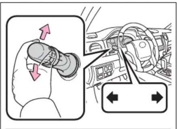
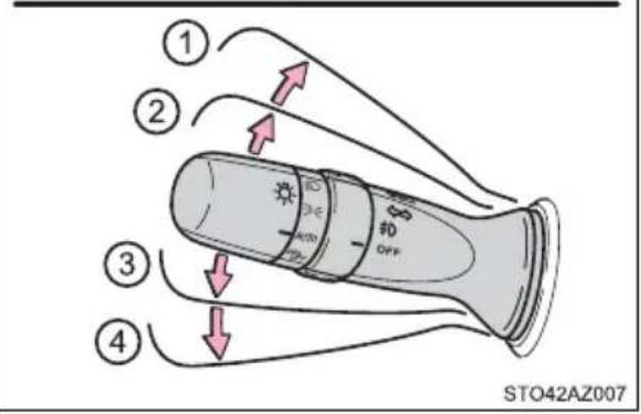
■Turn signals can be operated when
The engine switch is in ON.
If the indicator flashes faster than usual
Check that a light bulb in the front or rear turn signal lights has not burned out.
Parking brake
To set the parking brake, fully depress the parking brake pedal with your left foot while depressing the brake pedal with your right foot.
(Depressing the pedal again releases the parking brake.)
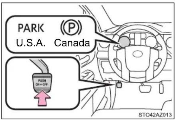
Parking the vehicle
→P. 184
■Usage in winter time
→P. 332

NOTICE
Before driving
Fully release the parking brake.
Driving the vehicle with the parking brake set will lead to brake components overheating, which may affect braking performance and increase brake wear.
Headlight switch
The headlights can be operated manually or automatically.
Operating instructions
Operating the switch turns on the lights as follows:
For U.S.A.
① AUTO The headlights, daytime running lights (→P. 237) and all the lights listed above turn on and off automatically. (When the engine switch is in ON.)
② ≧00 ≧ The side marker, parking, tail, license plate, instrument panel lights, and daytime running lights (→P. 237) turn on.
③ The headlights and all lights listed above (except daytime running lights) turn on.
④ DRL OFF The daytime running lights turn off.
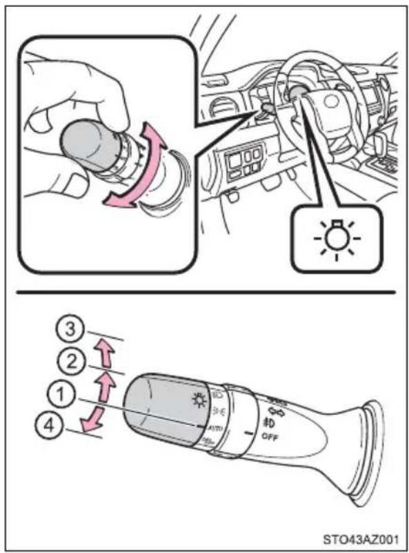
For Canada
① AUTO The headlights, daytime running lights (→P. 237) and all the lights listed above turn on and off automatically. (When the engine switch is in ON.)
② ≈00 ≲ The side marker, parking, tail, license plate, instrument panel lights, and daytime running lights (→P. 237) turn on.
③ The headlights and all lights listed above (except daytime running lights) turn on.
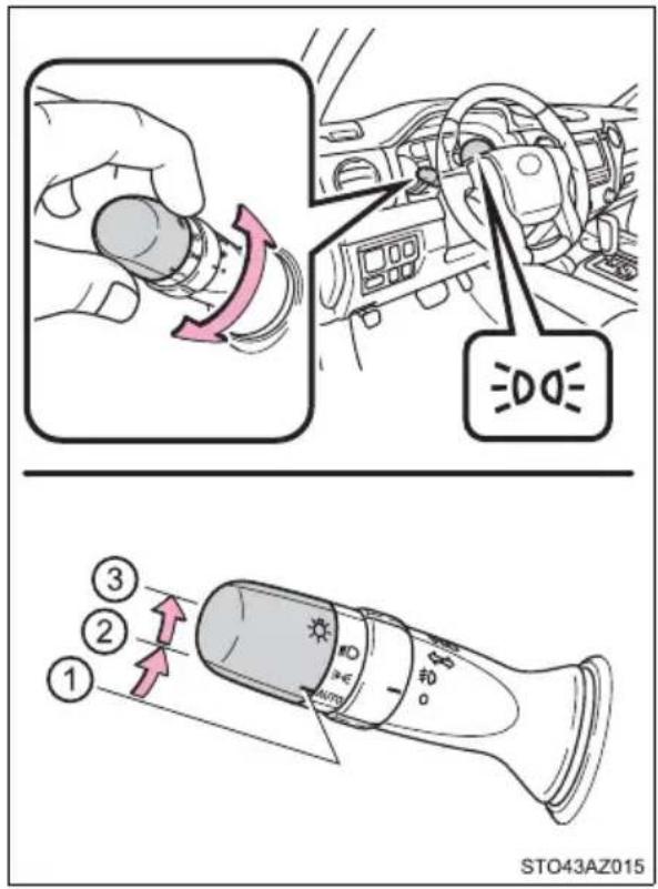
Turning on the high beam headlights
① With the headlights on, push the lever away from you to turn on the high beams.
Pull the lever toward you to the center position to turn the high beams off.
② Pull the lever toward you and release it to flash the high beams once.
You can flash the high beams with the headlights on or off.
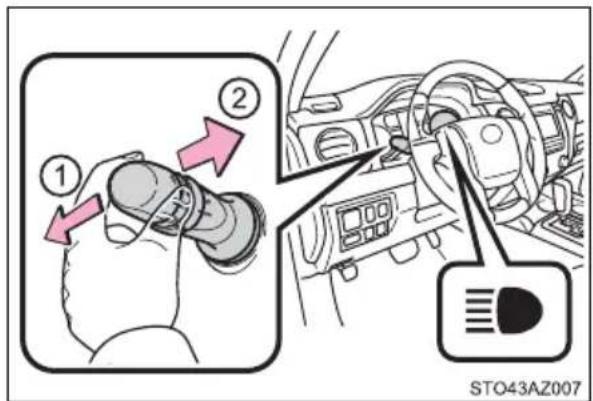
Manual headlight leveling dial
The level of the headlights can be adjusted according to the number of passengers and the loading condition of the vehicle.
① Raises the level of the headlights
② Lowers the level of the headlights
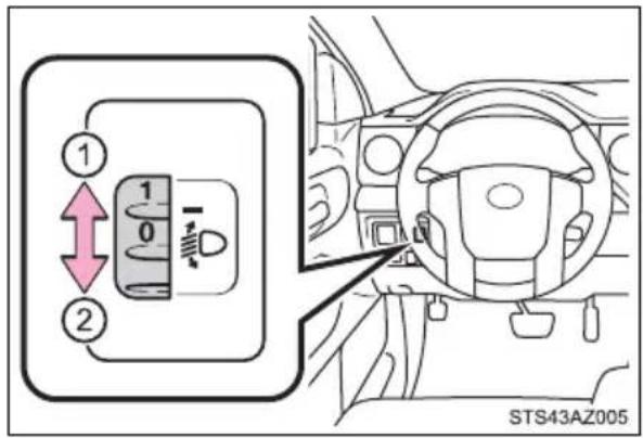
■Guide to dial settings
| Loading condition | Control switch position | |||
| Towing Hitch (Towing package) | Payload | Double Cab CrewMax | ||
| Standard Long Short | ||||
| None None 0 0 0 | ||||
| None | Maximum load | 2.5 2 2.5 | ||
| Maximum load | None 3.5 3 3.5 | |||
■Daytime running light system
●The daytime running lights illuminate using the same lights as the parking lights and illuminate brighter than the parking lights.
- To make your vehicle more visible to other drivers during daytime driving, the daytime running lights turn on automatically when all of the following conditions are met. (The daytime running lights are not designed for use at night.)
• The engine is running
• The parking brake is released
- The headlight switch is in the (Canada only), or position
*: When the surroundings are bright
The daytime running lights remain on after they illuminate, even if the parking brake is set again.
- For the U.S.A.: Daytime running lights can be turned off by operating the switch.
- For the Canada: Daytime running lights are not designed for use at night.
- Compared to turning on the headlights, the daytime running light system offers greater durability and consumes less electricity, so it can help improve fuel economy.
■ Headlight control sensor (vehicles with automatic headlight system)
The sensor may not function properly if an object is placed on the sensor, or anything that blocks the sensor is affixed to the windshield.
Doing so interferes with the sensor detecting the level of ambient light and may cause the automatic headlight system to malfunction.
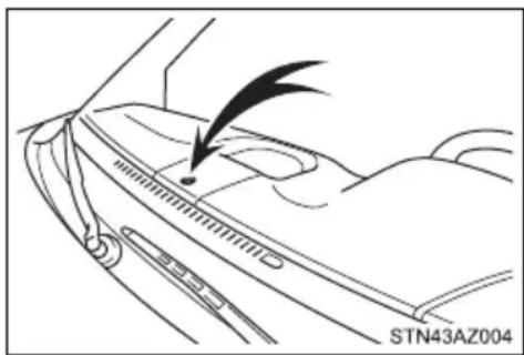
natural_image
Line drawing of a car interior showing a curved track and a directional arrow, with no readable text or symbols.■Automatic light off system
- When the headlights come on: The headlights and tail lights turn off 30 seconds after a door is opened and closed if the engine switch is turned to ACC or OFF. (The lights turn off immediately if the 🔒 button on the key is pressed after all the doors are locked.)
- When only the tail lights come on: The tail lights turn off automatically if the engine switch is tuned to ACC or OFF and the driver's door is opened.
Vehicles with automatic headlight system: If any of the doors is kept open, the lights automatically turn off after 20 minutes.
To turn the lights on again, turn the engine switch to ON, or turn the light switch off once and then back to ≥ or . ☐
Light reminder buzzer
A buzzer sounds when the key is removed from the engine switch and the driver's door is opened while the lights are turned on.
■ Customization that can be configured at Toyota dealer
Settings (automatic light off system) can be changed. (Customizable features: →P. 564)

NOTICE
■To prevent battery discharge
Do not leave the lights on longer than necessary when the engine is not running.
Automatic High Beam\*
The Automatic High Beam uses an in-vehicle front camera to assess the brightness of streetlights, the lights of vehicles ahead etc., and automatically turns the high beam on or off as necessary.

WARNING
■Limitations of the Automatic High Beam
Do not rely on the Automatic High Beam. Always drive safely, taking care to observe your surroundings and turning the high beam on or off manually if necessary.
■ To prevent incorrect operation of the Automatic High Beam system
Do not overload the vehicle.
Activating the Automatic High Beam system
1 Push the lever away from you with the headlight switch in or position.
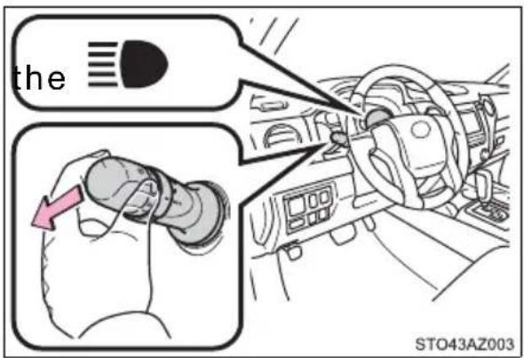
2 Press the Automatic High Beam switch.
The Automatic High Beam indicator will come on when the headlights are turned on automatically to indicate that the system is active.
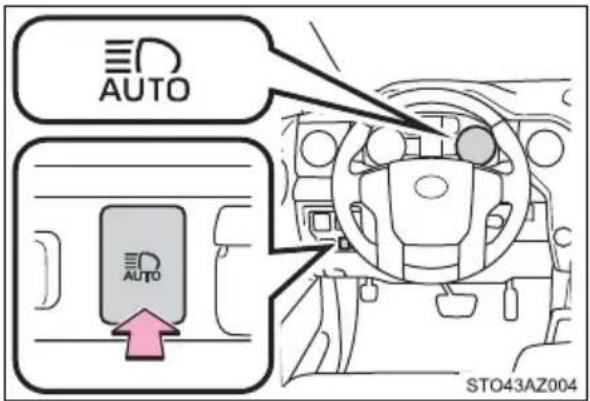
Turning the high beam on/off manually
■Switching to low beam
Pull the lever to the original position.
The Automatic High Beam indicator will turn off.
Push the lever away from you to activate the Automatic High Beam system again.
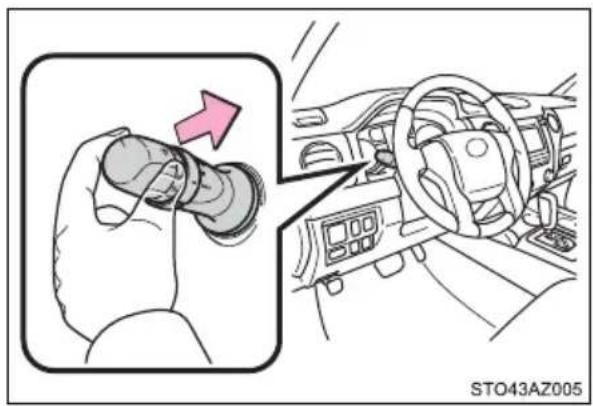
■ Switching to high beam
Press the Automatic High Beam switch.
The Automatic High Beam indicator will turn off and the high beam indicator will turn on.
Press the switch to activate the Automatic High Beam system again.
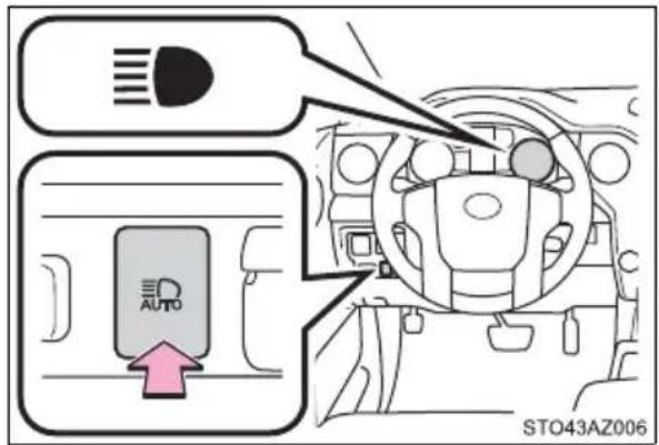
■High beam automatic turning on or off conditions
- When all of the following conditions are fulfilled, the high beam will be automatically turned on (after approximately 1 second):
- Vehicle speed is above approximately 21 mph (34 km/h).
- The area ahead of the vehicle is dark.
- There are no vehicles ahead with headlights or tail lights turned on.
- There are few streetlights on the road ahead.
- If any of the following conditions are fulfilled, the high beam will be automatically turned off:
- Vehicle speed drops below approximately 17 mph (27 km/h).
- The area ahead of the vehicle is not dark.
- Vehicles ahead have headlights or tail lights turned on.
- There are many streetlights on the road ahead.
■Front camera detection information
●The high beam may not be automatically turned off in the following situations:
- When oncoming vehicles suddenly appear from a curve
- When the vehicle is cut off in front of by another vehicle
- When vehicles ahead are hidden from sight due to repeated curves, road dividers or roadside trees
- When vehicles ahead appear from the faraway lane on wide road
- When vehicles ahead have no lights
● The high beam may be turned off if a vehicle ahead that is using fog lights without using the headlights is detected.
●House lights, street lights, traffic signals, and illuminated billboards or signs may cause the high beam to switch to the low beams, or the low beams to remain on.
● The following factors may affect the amount of time taken to turn the high beam on or off:
- The brightness of headlights, fog lights, and tail lights of vehicles ahead
- The movement and direction of vehicles ahead
- When a vehicle ahead only has operational lights on one side
- When a vehicle ahead is a two-wheeled vehicle
- The condition of the road (gradient, curve, condition of the road surface, etc.)
- The number of passengers and amount of luggage
● The high beam may be turned on or off when the driver does not expect it.
●Bicycles or similar objects may not be detected.
In the situations shown below, the system may not be able to accurately detect surrounding brightness levels. This may cause the low beams to remain on or the high beams to cause problems for pedestrians, vehicles ahead or other parties. In these cases, manually switch between the high and low beams.
- In bad weather (rain, snow, fog, sandstorms, etc.)
- The windshield is obscured by fog, mist, ice, dirt, etc.
- The windshield is cracked or damaged.
- The front camera is deformed or dirty.
- The front camera temperature is extremely high.
- Surrounding brightness levels are equal to those of headlights, tail lights or fog lights.
- Vehicles ahead have headlights that are either switched off, dirty, are changing color, or are not aimed properly.
- When driving through an area of intermittently changing brightness and darkness.
- When frequently and repeatedly driving ascending/descending roads, or roads with rough, bumpy or uneven surfaces (such as stone-paved roads, gravel tracks, etc.).
- When frequently and repeatedly taking curves or driving on a winding road.
- There is a highly reflective object ahead of the vehicle, such as a sign or a mirror.
- The back of a vehicle ahead is highly reflective, such as a container on a truck.
- The vehicle's headlights are damaged or dirty.
- The vehicle is listing or tilting, due to a flat tire, a trailer being towed etc.
- The high beam and low beam are repeatedly being switched between in an abnormal manner.
- The driver believes that the high beam may be causing problems or distress to other drivers or pedestrians nearby.
■Temporarily lowering sensor sensitivity
The sensitivity of the sensor can be temporarily lowered.
1 Turn the engine switch off while the following conditions are met.
- The headlight switch is in

AUTO
- The headlight switch lever is in high beam position.
• Automatic High Beam switch is on.
2 Turn the engine switch to ON.
3 Within 30 seconds after ,2 repeat pulling the headlight switch lever to the original position then pushing it to the high beam position quickly 10 times, then leave the lever in high beam position.
4 If the sensitivity is changed, the Automatic High Beam indicator is turn on and off 3 times.
Automatic High Beam (headlights) may turn on even the vehicle is stopped.
If “Headlight System Malfunction. Visit Your Dealer.” is displayed on the multi-information display
The system may be malfunctioning. Have the vehicle inspected by your Toyota dealer.
Fog light switch\*
The fog lights secure excellent visibility in difficult driving conditions, such as in rain and fog.
① OFF (U.S.A.) or (Canada) Turns the front fog lights off
② #0 Turns the front fog lights on
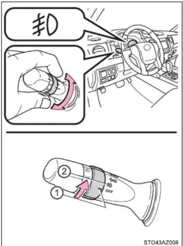
■Fog lights can be used when
The parking lights are on or the headlights are on in low beam.
Windshield wipers and washer
Operating the wiper lever
Operating the lever operates the wipers or washer as follows.
▶ Vehicles without intermittent type
① OFF (U.S.A.) or (Canada)
Off
② LO (U.S.A.) or (Canada) Low speed windshield wiper operation
③ HI (U.S.A.) or Canada)
High speed windshield
wiper operation
④ MIST (U.S.A.) or (Canada) Temporary operation
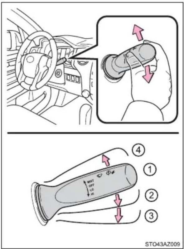
⑤ Washer operation Pulling the lever operates the washer.
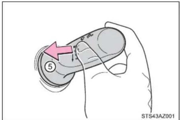
▶ Vehicles with intermittent type
① OFF (U.S.A.) or (Canada)
Off
② INT (U.S.A.) or Canada) Intermittent windshield wiper operation
③ LO (U.S.A.) or (Canada) Low speed windshield wiper operation
④ HI (U.S.A.) or Canada)
High speed windshield
wiper operation
⑤ MIST (U.S.A.) or (Canada) Temporary operation
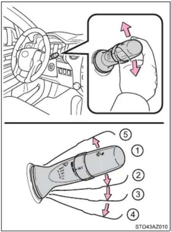
Wiper intervals can be adjusted when intermittent operation is selected.
⑥ Increases the intermittent wind-shield wiper frequency
⑦ Decreases the intermittent windshield wiper frequency
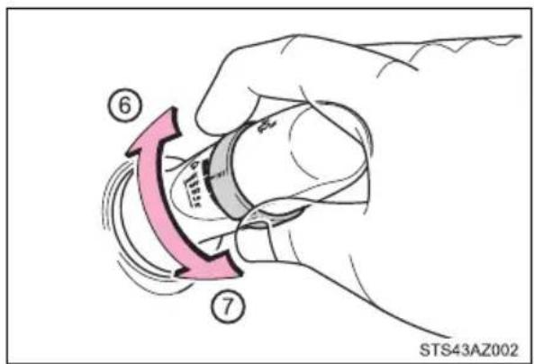
⑧ Washer/wiper dual operation
Pulling the lever operates the wipers and washer.
Wipers will automatically operate a couple of times after the washer squirts.
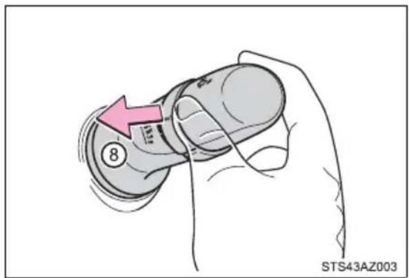
■The windshield wipers and washer can be operated when
The engine switch is in ON.
If no windshield washer fluid sprays
Check that the washer nozzles are not blocked if there is washer fluid in the windshield washer fluid reservoir.

WARNING
■Caution regarding the use of washer fluid
When it is cold, do not use the washer fluid until the windshield becomes warm. The fluid may freeze on the windshield and cause low visibility. This may lead to an accident, resulting in death or serious injury.

NOTICE
■When the windshield is dry
Do not use the wipers, as they may damage the windshield.
■When the washer fluid tank is empty
Do not operate the switch continually as the washer fluid pump may overheat.
When a nozzle becomes blocked
In this case, contact your Toyota dealer.
Do not try to clear it with a pin or other object. The nozzle will be damaged.
Opening the fuel tank cap
Perform the following steps to open the fuel tank cap:
Before refueling the vehicle
●Turn the engine switch to OFF and ensure that all the doors and windows are closed.
- Confirm the type of fuel.
Fuel types
→P. 542
■Fuel tank opening for unleaded gasoline
To help prevent incorrect fueling, your vehicle has a fuel tank opening that only accommodates the special nozzle on unleaded fuel pumps.
If the malfunction indicator lamp illuminates
The malfunction indicator lamp may illuminate erroneously if refueling is performed repeatedly when the fuel tank is nearly full.

WARNING
■When refueling the vehicle
Observe the following precautions while refueling the vehicle. Failure to do so may result in death or serious injury.
● After exiting the vehicle and before opening the fuel door, touch an unpainted metal surface to discharge any static electricity. It is important to discharge static electricity before refueling because sparks resulting from static electricity can cause fuel vapors to ignite while refueling.
● Always hold the grips on the fuel tank cap and turn it slowly to remove it. A whooshing sound may be heard when the fuel tank cap is loosened. Wait until the sound cannot be heard before fully removing the cap. In hot weather, pressurized fuel may spray out the filler neck and cause injury.
- Do not allow anyone that has not discharged static electricity from their body to come close to an open fuel tank.
- Do not inhale vaporized fuel.
Fuel contains substances that are harmful if inhaled.
- Do not smoke while refueling the vehicle.
Doing so may cause the fuel to ignite and cause a fire.
- Do not return to the vehicle or touch any person or object that is statically charged.
This may cause static electricity to build up, resulting in a possible ignition hazard.
When refueling
Observe the following precautions to prevent fuel overflowing from the fuel tank:
- Securely insert the fuel nozzle into the fuel filler neck.
- Stop filling the tank after the fuel nozzle automatically clicks off.
- Do not top off the fuel tank.

NOTICE
Refueling
Do not spill fuel during refueling.
Doing so may damage the vehicle, such as causing the emission control system to operate abnormally or damaging fuel system components or the vehicle's painted surface.
Opening the fuel tank cap
1 Open the fuel filler door.
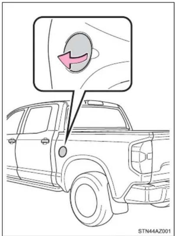
2 Turn the fuel tank cap slowly open, and hang the fuel tank cap on the back of the fuel filler door.
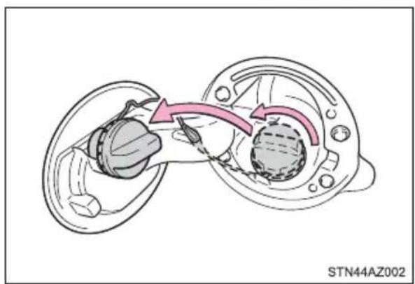
natural_image
Diagram of a mechanical assembly showing two components with directional arrows indicating motion (no text or symbols)Closing the fuel tank cap
After refueling, turn the fuel tank cap until you hear a click. Once the cap is released, it will turn slightly in the opposite direction.
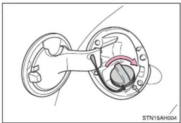
natural_image
Technical diagram of a mechanical assembly with no visible text or symbols■ Closing the fuel tank cap
Tighten the fuel tank cap until 1 click is heard. Otherwise a malfunction indicator lamp may come on.

WARNING
■When replacing the fuel tank cap
Do not use anything but a genuine Toyota fuel tank cap designed for your vehicle. Doing so may cause a fire or other incident which may result in death or serious injury.
Toyota Safety Sense P\*
The Toyota Safety Sense P consists of the following drive assist systems and contributes to a safe and comfortable driving experience:
Driving assist system
◆PCS (Pre-Collision System) *
→P.260
◆LDA (Lane Departure Alert) *
→P.272
◆Automatic High Beam *
→P.239
◆ Dynamic radar cruise control *
→P.280

WARNING
Toyota Safety Sense P
The Toyota Safety Sense P is designed to operate under the assumption that the driver will drive safely, and is designed to help reduce the impact to the occupants and the vehicle in the case of a collision or assist the driver in normal driving conditions.
As there is a limit to the degree of recognition accuracy and control performance that this system can provide, do not overly rely on this system. The driver is always responsible for paying attention to the vehicle's surroundings and driving safely.
Sensors
Two types of sensors, located behind the front grille and windshield, detect information necessary to operate the drive assist systems.
① Radar sensor
② Front camera
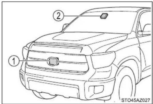

WARNING
■To avoid malfunction of the radar sensor
Observe the following precautions.
Otherwise, the radar sensor may not operate properly, possibly leading to an accident resulting in death or serious injury.
- Keep the radar sensor and radar sensor cover clean at all times.
① Radar sensor
② Radar sensor cover
If the front of the radar sensor or the front or back of the radar sensor cover is dirty or covered with water droplets, snow, etc., clean it.
Clean the radar sensor and radar sensor cover with a soft cloth to avoid damaging them.
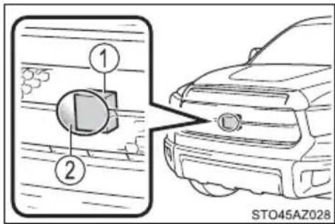

WARNING
- Do not attach accessories, stickers (including transparent stickers) or other items to the radar sensor, radar sensor cover or surrounding area.
- Do not subject the radar sensor or its surrounding area to a strong impact. If the radar sensor, front grille, or front bumper has been subjected to a strong impact, have the vehicle inspected by your Toyota dealer.
- Do not disassemble the radar sensor.
- Do not modify or paint the radar sensor or radar sensor cover.
- In the following cases, the radar sensor must be recalibrated. Contact your Toyota dealer for details.
- When the radar sensor or front grille are removed and installed, or replaced
- When the front bumper is replaced
■To avoid malfunction of the front camera
Observe the following precautions.
Otherwise, the front camera may not operate properly, possibly leading to an accident resulting in death or serious injury.
- Keep the windshield clean at all times.
- If the windshield is dirty or covered with an oily film, water droplets, snow, etc., clean the windshield.
- If a glass coating agent is applied to the windshield, it will still be necessary to use the windshield wipers to remove water droplets, etc. from the area of the windshield in front of the front camera.
- If the inner side of the windshield where the front camera is installed is dirty, contact your Toyota dealer.
- Do not attach objects, such as stickers, transparent stickers, etc., to the outer side of the windshield in front of the front camera (shaded area in the illustration).
A: From the top of the windshield to approximately 0.4 in. (1 cm) below the bottom of the front camera
B: Approximately 7.9 in. (20 cm) (Approximately 4.0 in. [10 cm] to the right and left from the center of the front camera)
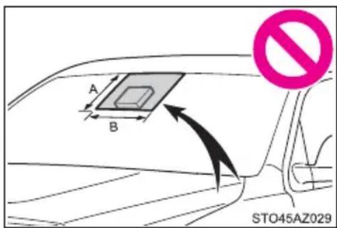

WARNING
- If the part of the windshield in front of the front camera is fogged up or covered with condensation, or ice, use the windshield defogger to remove the fog, condensation, or ice. (→P. 342, 349)
- If water droplets cannot be properly removed from the area of the windshield in front of the front camera by the windshield wipers, replace the wiper insert or wiper blade.
- Do not attach window tint to the windshield.
- Replace the windshield if it is damaged or cracked. After replacing the windshield, the front camera must be recalibrated. Contact your Toyota dealer for details.
- Do not allow liquids to contact the front camera.
- Do not allow bright lights to shine into the front camera.
- Do not dirty or damage the front camera. When cleaning the inside of the windshield, do not allow glass cleaner to contact the lens of the front camera. Also, do not touch the lens. If the lens is dirty or damaged, contact your Toyota dealer.
- Do not subject the front camera to a strong impact.
- Do not change the installation position or direction of the front camera or remove it.
- Do not disassemble the front camera.
- Do not modify any components of the vehicle around the front camera (inside rear view mirror, etc.) or ceiling.
- Do not attach any accessories to the hood, front grille or front bumper that may obstruct the front camera. Contact your Toyota dealer for details.
- If a surfboard or other long object is to be mounted on the roof, make sure that it will not obstruct the front camera.
- Do not modify the headlights or other lights.
Certification
For vehicles sold in the U.S.A.
Model: ARS4-B
IC: 4135A-ARS4B
FCC ID: OAYARS4B
This device complies with Part 15 of the FCC Rules and with Industry Canada licence-exempt RSS standard(s). Operation is subject to the following two conditions:
(1) This device may not cause harmful interference, and
(2) This device must accept any interference received, including interference that may cause undesired operation.
Radiofrequency radiation exposure Information:
This equipment complies with FCC and IC radiation exposure limits set forth for an uncontrolled environment. This equipment should be installed and operated with minimum distance of 30 cm between the radiator and your body.
This transmitter must not be co-Located or operating in conjunction with any other antenna or transmitter.
Changes or modifications not expressly approved by the party responsible for compliance could void the user's authority to operate the equipment.
For vehicles sold in Canada
Model: ARS4-B
IC: 4135A-ARS4B
FCC ID: OAYARS4B
This device complies with Part 15 of the FCC Rules and with Industry Canada licence-exempt RSS standard(s). Operation is subject to the following two conditions:
(1) This device may not cause harmful interference, and
(2) This device must accept any interference received, including interference that may cause undesired operation.
Radiofrequency radiation exposure Information:
This equipment complies with FCC and IC radiation exposure limits set forth for an uncontrolled environment.
This equipment should be installed and operated with minimum distance of 30 cm between the radiator and your body.
This transmitter must not be co-located or operating in conjunction with any other antenna or transmitter.
Changes or modifications not expressly approved by the party responsible for compliance could void the user's authority to operate the equipment.
If a warning message is displayed on the multi-information display
A system may be temporarily unavailable or there may be a malfunction in the system.
- In the following situations, perform the actions specified in the table. When the normal operating conditions are detected, the message will disappear and the system will become operational.
If the message does not disappear, contact your Toyota dealer.
| Situation Actions | |
| When the area around a camera is covered with dirt, moisture (fogged up, covered with condensation, ice, etc.), or other foreign matter | Using the wiper and A/C function, remove the dirt and other attached matter ( P. 342, 349). |
| When the temperature around the front camera is outside of the operational range, such as when the vehicle is in the sun or in an extremely cold environment | If the front camera is hot, such as after the vehicle had been parked in the sun, use the air conditioning system to decrease the temperature around the front camera. If a sunshade was used when the vehicle was parked, depending on its type, the sunlight reflected from the surface of the sunshade may cause the temperature of the front camera to become excessively high. |
| If the front camera is cold, such after the vehicle is parked in an extremely cold environment, use the air conditioning system to increase the temperature around the front camera. | |
| The area in front of the front camera is obstructed, such as when the hood is open or a sticker is attached to the part of the windshield in front of the front camera. | Close the hood, remove the sticker, etc. to clear the obstruction. |
| When “Pre-Collision System Unavailable” is displayed | Check whether there is attached materials on the radar sensor and radar sensor cover, and if there is, remove it. |
- In the following situations, if the situation has changed (or the vehicle has been driven for some time) and the normal operating conditions are detected, the message will disappear and the system will become operational.
If the message does not disappear, contact your Toyota dealer.
- When the temperature around the radar sensor is outside of the operational range, such as when the vehicle is in the sun or in an extremely cold environment
- When the front camera cannot detect objects in front of the vehicle, such as when driving in the dark, snow, or fog, or when bright lights are shining into the front camera
- Depending on the conditions in the vicinity of the vehicle, the radar may judge the surrounding environment can not be properly recognized. In that case, “Pre-Collision System Unavailable” is displayed.
PCS (Pre-Collision System)\*
The pre-collision system uses a radar sensor and front camera to detect vehicles and pedestrians in front of your vehicle. When the system determines that the possibility of a frontal collision with a vehicle or pedestrian is high, a warning operates to urge the driver to take evasive action and the potential brake pressure is increased to help the driver avoid the collision. If the system determines that the possibility of a frontal collision with a vehicle or pedestrian is extremely high, the brakes are automatically applied to help avoid the collision or help reduce the impact of the collision.
The pre-collision system can be disabled/enabled and the warning timing can be changed. ( P. 264)
◆Pre-collision warning
When the system determines that the possibility of a frontal collision is high, a buzzer will sound and a warning message will be displayed on the multi-information display to urge the driver to take evasive action.
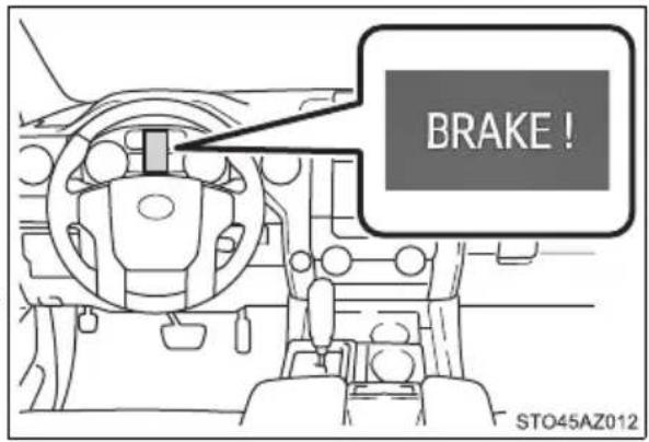
◆Pre-collision brake assist
When the system determines that the possibility of a frontal collision is high, the system applies greater braking force in relation to how strongly the brake pedal is depressed.
◆Pre-collision braking
When the system determines that the possibility of a frontal collision is high, the system warns the driver. If the system determines that the possibility of a frontal collision is extremely high, the brakes are automatically applied to help avoid the collision or reduce the collision speed.

WARNING
■Limitations of the pre-collision system
●The driver is solely responsible for safe driving. Always drive safely, taking care to observe your surroundings.
Do not use the pre-collision system instead of normal braking operations under any circumstances. This system will not prevent collisions or lessen collision damage or injury in every situation. Do not overly rely on this system. Failure to do so may lead to an accident, resulting in death or serious injury.
Although this system is designed to help avoid a collision or help reduce the impact of the collision, its effectiveness may change according to various conditions, therefore the system may not always be able to achieve the same level of performance. Read the following conditions carefully. Do not overly rely on this system and always drive carefully.
- Conditions under which the system may operate even if there is no possibility of a collision: P. 267
- Conditions under which the system may not operate properly: P. 269
- Do not attempt to test the operation of the pre-collision system yourself. Depending on the objects used for testing (dummies, cardboard objects imitating detectable objects, etc.), the system may not operate properly possibly leading to an accident.
■Pre-collision braking
- When the pre-collision braking function is operating, a large amount of braking force will be applied.
- If the vehicle is stopped by the operation of the pre-collision braking function, the pre-collision braking function operation will be canceled after approximately 2 seconds. Depress the brake pedal as necessary.
- The pre-collision braking function may not operate if certain operations are performed by the driver. If the accelerator pedal is being depressed strongly or the steering wheel is being turned, the system may determine that the driver is taking evasive action and possibly prevent the pre-collision braking function from operating.
In some situations, while the pre-collision braking function is operating, operation of the function may be canceled if the accelerator pedal is depressed strongly or the steering wheel is turned and the system determines that the driver is taking evasive action. - If the brake pedal is being depressed, the system may determine that the driver is taking evasive action and possibly delay the operation timing of the pre-collision braking function.

WARNING
■When to disable the pre-collision system
In the following situations, disable the system, as it may not operate properly, possibly leading to an accident resulting in death or serious injury:
●When the vehicle is being towed
- When your vehicle is towing another vehicle
- When transporting the vehicle via truck, boat, train or similar means of transportation
- When the vehicle is raised on a lift with the engine running and the tires are allowed to rotate freely
- When inspecting the vehicle using a drum tester such as a chassis dynamometer or speedometer tester, or when using an on vehicle wheel balancer
- When a strong impact is applied to the front bumper or front grille, due to an accident or other reasons
- If the vehicle cannot be driven in a stable manner, such as when the vehicle has been in an accident or is malfunctioning
●When the vehicle is driven in a sporty manner or off-road
- When the tires are not properly inflated
- When the tires are very worn
●When tires of a size other than specified are installed
●When tire chains are installed
- When a compact spare tire or an emergency tire puncture repair kit is used
- If equipment (snow plow, etc.) that may obstruct the radar sensor or front camera is temporarily installed to the vehicle
Changing settings of the pre-collision system
■Enabling/disabling the pre-collision system
The pre-collision system can be enabled/disabled on ⚙ (→P. 565) of the multi-information display.
The system is automatically enabled each time the engine switch is turned to ON.
If the system is disabled, the PCS warning light will turn on and a message will be displayed on the multi-information display.
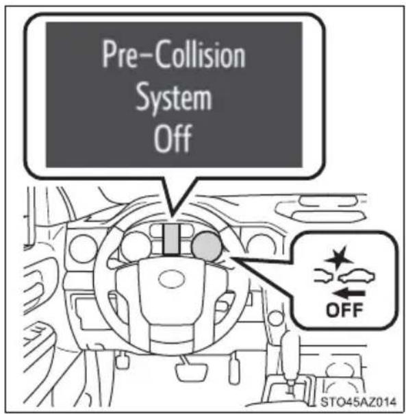
■Changing the pre-collision warning timing
The pre-collision warning timing can be changed on ⚙ (→P. 565) of the multi-information display.
The operation timing setting is retained when the engine switch is turned off.
① Far
The warning will begin to operate earlier than with the default timing.
② Middle
This is the default setting.
③ Near
The warning will begin to operate later than with the default timing.
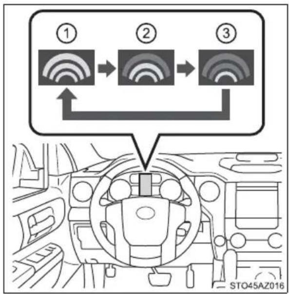
flowchart
graph TD
    A["①"] --> B["②"]
    B --> C["③"]
    C --> D["Top: Sensor Network"]
    style A fill:#f9f,stroke:#333
    style B fill:#f9f,stroke:#333
    style C fill:#f9f,stroke:#333
    style D fill:#ccf,stroke:#333
■Operational conditions
The pre-collision system is enabled and the system determines that the possibility of a frontal collision with a vehicle or pedestrian is high.
Each function is operational at the following speeds:
●Pre-collision warning:
- Vehicle speed is between approximately 7 and 110mph (10 and 180km/h ). (For detecting a pedestrian, vehicle speed is between approximately 7 and 50mph [10 and 80km/h .)
- The relative speed between your vehicle and the vehicle or pedestrian ahead is approximately 7 mph (10 km/h) or more.
●Pre-collision brake assist:
- Vehicle speed is between approximately 20 and 110 mph (30 and 180 km/h). (For detecting a pedestrian, vehicle speed is between approximately 20 and 50 mph [30 and 80 km/h].)
- The relative speed between your vehicle and the vehicle or pedestrian ahead is approximately 20 mph (30 km/h) or more.
●Pre-collision braking:
- Vehicle speed is between approximately 7 and 110mph (10 and 180km/h ). (For detecting a pedestrian, vehicle speed is between approximately 7 and 50mph [10 and 80km/h .)
- The relative speed between your vehicle and the vehicle or pedestrian ahead is approximately 7 mph (10 km/h) or more.
The system may not operate in the following situations:
- If a battery terminal has been disconnected and reconnected and then the vehicle has not been driven for a certain amount of time
- If the shift lever is in R
- If VSC is disabled (only the pre-collision warning function will be operational)
- If the low speed four-wheel drive indicator is illuminated (only the pre-collision warning function will be operational)
■Pedestrian detection function
The pre-collision system detects pedestrians based on the size, profile, and motion of a detected object. However, a pedestrian may not be detected depending on the surrounding brightness and the motion, posture, and angle of the detected object, preventing the system from operating properly. ( P. 271)
natural_image
Two black silhouette figures of human and walking individuals side by side, no text or symbols present.■ Cancellation of the pre-collision braking
If either of the following occur while the pre-collision braking function is operating, it will be canceled:
●The accelerator pedal is depressed strongly.
●The steering wheel is turned sharply or abruptly.
Conditions under which the system may operate even if there is no possibility of a collision
In some situations such as the following, the system may determine that there is a possibility of a frontal collision and operate.
- When passing a vehicle or pedestrian
- When changing lanes while overtaking a preceding vehicle
- When overtaking a preceding vehicle that is changing lanes
- When overtaking a preceding vehicle that is making a left/right turn
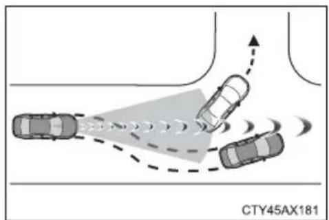
- When passing a vehicle in an oncoming lane that is stopped to make a right/left turn
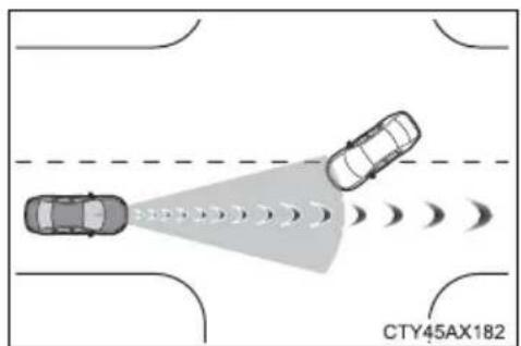
natural_image
Top-down diagram of two cars on a road with a shaded traffic cone and curved motion lines (no text or symbols)- When driving on a road where relative location to vehicle ahead in an adjacent lane may change, such as on a winding road
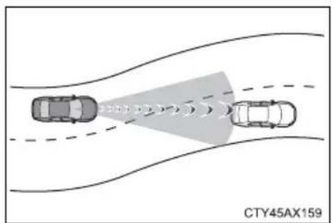
- When rapidly closing on a vehicle ahead
- If the front of the vehicle is raised or lowered, such as when the road surface is uneven or undulating
- When approaching objects on the roadside, such as guardrails, utility poles, trees, or walls
- When there is a vehicle, pedestrian, or object by the roadside at the entrance of a curve
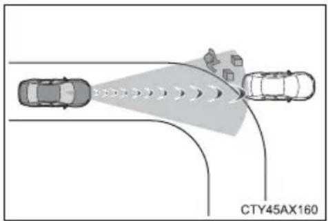
- When driving on a narrow path surrounded by a structure, such as in a tunnel or on an iron bridge
- When there is a metal object (manhole cover, steel plate, etc.), steps, or a protrusion on the road surface or roadside
- When a crossing pedestrian approaches very close to the vehicle
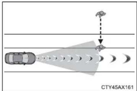
- When passing through a place with a low structure above the road (low ceiling, traffic sign, etc.)
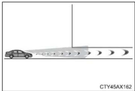
natural_image
Diagram showing a car approaching a road with multiple curved lanes, no text or symbols present- When passing under an object (billboard, etc.) at the top of an uphill road
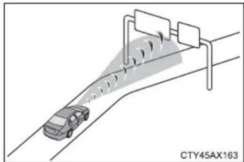
natural_image
Diagram of a car driving on a road with traffic light and sensor array (no text or symbols)- When rapidly closing on an electric toll gate barrier, parking area barrier, or other barrier that opens and closes
- When using an automatic car wash
- When driving through or under objects that may contact the vehicle, such as thick grass, tree branches, or a banner
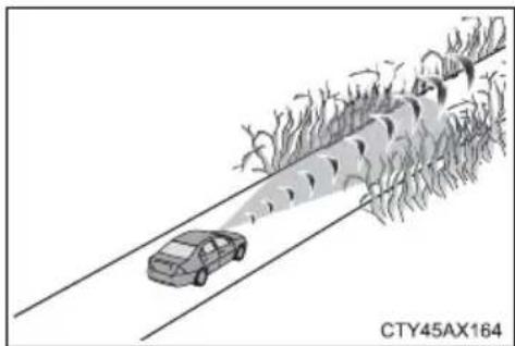
natural_image
Illustration of a car driving on a road with trees and a vehicle in motion (no text or symbols)- When the vehicle is hit by water, snow, dust, etc., from a vehicle ahead
- When driving through steam or smoke
- When there are patterns or paint on the road or a wall that may be mistaken for a vehicle or pedestrian
- When driving near an object that reflects radio waves, such as a large truck or guardrail
- When driving near a TV tower, broadcasting station, electric power plant, or other location where strong radio waves or electrical noise may be present
■ Situations in which the system may not operate properly
- In some situations such as the following, a vehicle may not be detected by the radar sensor and front camera, preventing the system from operating properly:
- If an oncoming vehicle is approaching your vehicle
- If a vehicle ahead is a motorcycle or bicycle
- When approaching the side or front of a vehicle
- If a preceding vehicle has a small rear end, such as an unloaded truck
- If a preceding vehicle has a low rear end, such as a low bed trailer
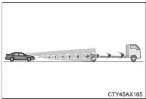
natural_image
Diagram showing a car approaching a truck with motion lines, labeled CTY45AX165 (no text or symbols on the diagram itself)- If a vehicle ahead is carrying a load which protrudes past its rear bumper
- If a vehicle ahead has extremely high ground clearance
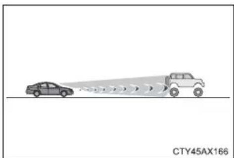
natural_image
Diagram showing two cars on a road with a light source, no text or symbols present- If a vehicle ahead is irregularly shaped, such as a tractor or side car
- If the sun or other light is shining directly on a vehicle ahead
-
If a vehicle cuts in front of your vehicle or emerges from beside a vehicle
-
If a vehicle ahead makes an abrupt maneuver (such as sudden swerving, acceleration or deceleration)
- When suddenly cutting behind a preceding vehicle
- When a vehicle ahead is not directly in front of your vehicle
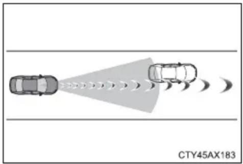
natural_image
Diagram showing two cars approaching a target vehicle with motion lines, labeled CTY45AX183 (no text on diagram itself)- When driving in inclement weather such as heavy rain, fog, snow or a sandstorm
- When the vehicle is hit by water, snow, dust, etc., from a vehicle ahead
- When driving through steam or smoke
- When driving in a place where the surrounding brightness changes suddenly, such as at the entrance or exit of a tunnel
- When a very bright light, such as the sun or the headlights of oncoming traffic, shines directly into the front camera
- When the surrounding area is dim, such as at dawn or dusk, or while at night or in a tunnel
• After the engine has started the vehicle has not been driven for a certain amount of time - While making a left/right turn and for a few seconds after making a left/right turn
- While driving on a curve and for a few seconds after driving on a curve
- If your vehicle is skidding
- If the front of the vehicle is raised or lowered
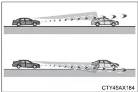
- If the wheels are misaligned
- If a wiper blade is blocking the front camera
• The vehicle is wobbling. - The vehicle is being driven at extremely high speeds.
- When driving on a hill
- If the radar sensor or front camera is misaligned
- In some situations such as the following, sufficient braking force may not be obtained, preventing the system from performing properly:
- If the braking functions cannot operate to their full extent, such as when the brake parts are extremely cold, extremely hot, or wet
- If the vehicle is not properly maintained (brakes or tires are excessively worn, improper tire inflation pressure, etc.)
- When the vehicle is being driven on a gravel road or other slippery surface
- Some pedestrians such as the following may not be detected by the radar sensor and front camera, preventing the system from operating properly:
- Pedestrians shorter than approximately 3.2 ft. (1 m) or taller than approximately 6.5 ft. (2 m)
- Pedestrians wearing oversized clothing (a rain coat, long skirt, etc.), making their silhouette obscure
- Pedestrians who are carrying large baggage, holding an umbrella, etc., hiding part of their body
- Pedestrians who are bending forward or squatting
- Pedestrians who are pushing a stroller, wheelchair, bicycle or other vehicle
- Groups of pedestrians which are close together
- Pedestrians who are wearing white and look extremely bright
- Pedestrians in the dark, such as at night or while in a tunnel
- Pedestrians whose clothing appears to be nearly the same color or brightness as their surroundings
- Pedestrians near walls, fences, guardrails, or large objects
- Pedestrians who are on a metal object (manhole cover, steel plate, etc.) on the road
- Pedestrians who are walking fast
- Pedestrians who are changing speed abruptly
- Pedestrians running out from behind a vehicle or a large object
- Pedestrians who are extremely close to the side of the vehicle (outside rear view mirror, etc.)
If VSC is disabled
- If VSC is disabled (→P. 323), the pre-collision brake assist and pre-collision braking functions are also disabled.
● The PCS warning light will turn on and “VSC Turned Off Pre-Collision Brake System Unavailable” will be displayed on the multi-information display.
LDA (Lane Departure Alert)\*
Summary of functions
When driving on roads with white (yellow) lines, this function alerts the driver when the vehicle might depart from its lane.
The LDA system recognizes visible white (yellow) lines with the front camera on the upper portion of the windshield.
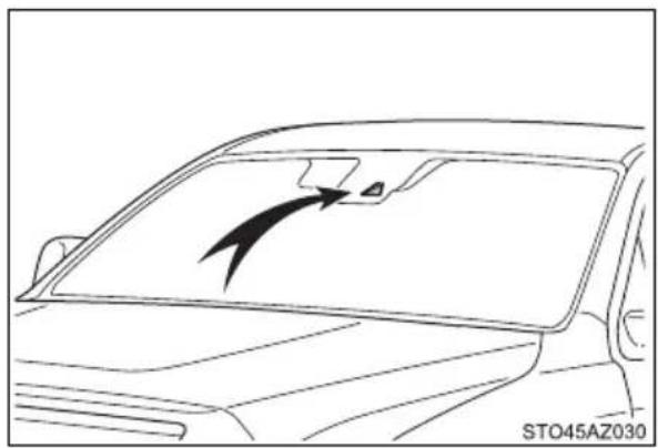
natural_image
Line drawing of a car's frontview with a black arrow pointing to the windshield area (no text or symbols)Functions included in LDA system
◆Lane departure alert function
When the system determines that the vehicle might depart from its lane, a warning is displayed on the multi-information display and the warning buzzer sounds to alert the driver.
When the warning buzzer sounds, check the surrounding road situation and carefully operate the steering wheel to move the vehicle back to the center of the lane.
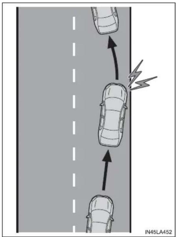
◆ Vehicle sway warning
When the vehicle is swaying or appears as if it may depart from its lane multiple times, the warning buzzer sounds and a message is displayed on the multi-information display to alert the driver.
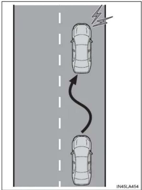

WARNING
■Before using LDA system
Do not rely solely upon the LDA system. The LDA system does not automatically drive the vehicle or reduce the amount of attention that must be paid to the area in front of the vehicle. The driver must always assume full responsibility for driving safely by always paying careful attention to the surrounding conditions and operating the steering wheel to correct the path of the vehicle. Also, the driver must take adequate breaks when fatigued, such as from driving for a long period of time.
Failure to perform appropriate driving operations and pay careful attention may lead to an accident, resulting in death or serious injury.
■To avoid operating LDA system by mistake
When not using the LDA system, use the LDA switch to turn the system off.
■Situations unsuitable for LDA system
Do not use the LDA system in the following situations.
The system may not operate properly and lead to an accident, resulting in death or serious injury.
●A spare tire, tire chains, etc., are equipped.
- Objects or patterns that could be mistaken for white (yellow) lines are present on the side of the road (guardrails, curbs, reflective poles, etc.).
●Vehicle is driven on a snow-covered road.
● White (yellow) lines are difficult to see due to rain, snow, fog, dust, etc.
● Asphalt repair marks, white (yellow) line marks, etc., are present due to road repair.
● Vehicle is driven in a temporary lane or restricted lane due to construction work.
●Vehicle is driven in a construction zone.

WARNING
■ Preventing LDA system malfunctions and operations performed by mistake
- Do not modify the headlights or place stickers, etc., on the surface of the lights.
- Do not modify the suspension, etc. If the suspension, etc., needs to be replaced, contact your Toyota dealer.
- Do not install or place anything on the hood or grille. Also, do not install a grille guard (bull bars, kangaroo bar, etc.).
● If your windshield needs repairs, contact your Toyota dealer.
Turning LDA system on
Press the LDA switch to turn the LDA system on.
The LDA indicator illuminates and a message is displayed on the multi-information display.
Press the LDA switch again to turn the LDA system off.
When the LDA system is turned on or off, operation of the LDA system continues in the same condition the next time the engine is started.
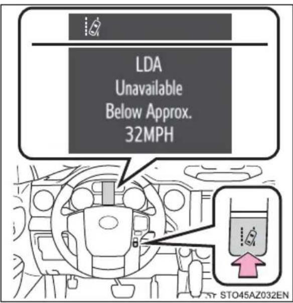
Indications on multi-information display
① LDA indicator
The illumination condition of the indicator informs the driver of the system operation status.
Illuminated in green:
LDA system is operating.
Flashing in yellow:
Lane departure alert function is operating.
② Lane departure alert function display
Displayed when the multi-information display is switched to the driving assist system information screen.
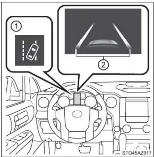
▶ Inside of displayed white lines is white
▶ Inside of displayed white lines is black
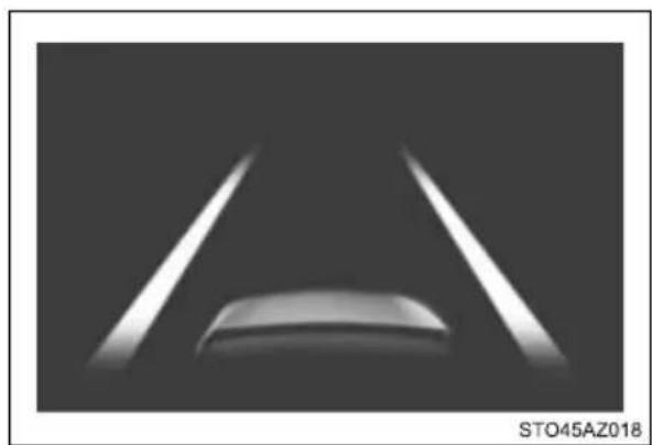
natural_image
Exterior view of a modern office building (no signage)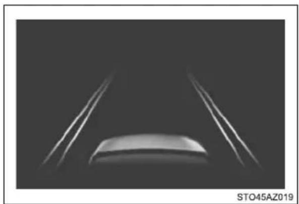
natural_image
Close-up of a car's front wheel and side blades against a dark background (no text or symbols visible)Indicates that the system is recognizing white (yellow) lines. When the vehicle departs from its lane, the white line displayed on the side the vehicle departs from flashes orange.
Indicates that the system is not able to recognize white (yellow) lines or is temporarily canceled.
■Operation conditions of each function
●Lane departure alert function
This function operates when all of the following conditions are met.
- LDA is turned on.
- Vehicle speed is approximately 32 mph (50 km/h) or more.
- System recognizes white (yellow) lines.
- Width of traffic lane is approximately 9.8 ft. (3 m) or more.
- Turn signal lever is not operated.
- Vehicle is driven on a straight road or around a gentle curve with a radius of more than approximately 492 ft. (150 m).
- No system malfunctions are detected. (→P. 279)
● Vehicle sway warning function
This function operates when all of the following conditions are met.
- Setting for “ ⚠️ Warning” in 📄 screen of the multi-information display is set to on. (→P. 111)
- Vehicle speed is approximately 32 mph (50 km/h) or more.
- Width of traffic lane is approximately 9.8 ft. (3 m) or more.
- No system malfunctions are detected. ( P. 279)
■Temporary cancellation of functions
When the operation conditions are no longer met, a function may be temporarily canceled. However, when the operation conditions are met again, operation of the function is automatically restored. ( P. 277)
■Lane departure alert function
The warning buzzer may be difficult to hear due to external noise, audio play-back, etc.
■ Vehicle sway warning function
When the system determines that the vehicle is swaying while the vehicle sway warning function is operating, a buzzer sounds and a warning message urging the driver to rest and the symbol shown in the illustration are simultaneously displayed on the multi-information display.
natural_image
Simple icon of a steaming cup on a saucer, no text or symbols presentDepending on the vehicle and road conditions, the warning may not operate.
■ White (yellow) lines are only on one side of road
The LDA system will not operate for the side on which white (yellow) lines could not be recognized.
■Conditions in which functions may not operate properly
In the following situations, the front camera may not detect white (yellow) lines and various functions may not operate normally.
- There are shadows on the road that run parallel with, or cover, the white (yellow) lines.
● The vehicle is driven in an area without white (yellow) lines, such as in front of a tollgate or checkpoint, or at an intersection, etc.
●The white (yellow) lines are cracked, “Botts’ dots”, “Raised pavement marker” or stones are present.
● The white (yellow) lines cannot be seen or are difficult to see due to sand, etc.
● The vehicle is driven on a road surface that is wet due to rain, puddles, etc.
● The traffic lines are yellow (which may be more difficult to recognize than lines that are white).
●The white (yellow) lines cross over a curb, etc.
●The vehicle is driven on a bright surface, such as concrete.
● The vehicle is driven on a surface that is bright due to reflected light, etc.
● The vehicle is driven in an area where the brightness changes suddenly, such as at the entrances and exits of tunnels, etc.
● Light from the headlights of an oncoming vehicle, the sun, etc., enters the camera.
●The vehicle is driven where the road diverges, merges, etc.
●The vehicle is driven on a slope.
● The vehicle is driven on a road which tilts left or right, or a winding road.
●The vehicle is driven on an unpaved or rough road.
●The vehicle is driven around a sharp curve.
●The traffic lane is excessively narrow or wide.
● The vehicle is extremely tilted due to carrying heavy luggage or having improper tire pressure.
●The distance to the preceding vehicle is extremely short.
●The vehicle is moving up and down a large amount due to road conditions during driving (poor roads or road seams).
●The headlight lenses are dirty and emit a faint amount of light at night, or the beam axis has deviated.
●The vehicle has just changed lanes or crossed an intersection.
■Warning message
Warning messages are used to indicate a system malfunction or to inform the driver of the need for caution while driving. ( P. 493)
Customization
The following settings can be changed.
| Function Setting details | |
| Lane departure alert function Adjust alert sensitivity | |
| Vehicle sway warning | Turn function on and off |
| Adjust alert sensitivity | |
For how to change settings, refer to P. 564.
Dynamic radar cruise control\*
Summary of functions
In vehicle-to-vehicle distance control mode, the vehicle automatically accelerates and decelerates to match the speed changes of the preceding vehicle even if the accelerator pedal is not depressed. In constant speed control mode, the vehicle runs at a fixed speed.
Use the dynamic radar cruise control on freeways and highways.
● Vehicle-to-vehicle distance control mode ( P. 283)
● Constant speed control mode ( P. 289)
① Vehicle-to-vehicle distance switch
② Display
③ Indicators
④ Set speed
⑤ Cruise control switch
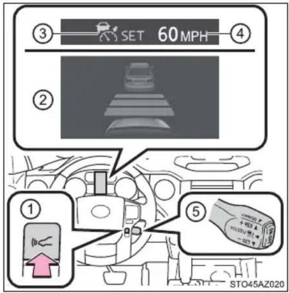

WARNING
■Before using dynamic radar cruise control
- Driving safely is the sole responsibility of the driver. Do not rely solely on the system, and drive safely by always paying careful attention to your surroundings.
- The dynamic radar cruise control provides driving assistance to reduce the driver's burden. However, there are limitations to the assistance provided. Read the following conditions carefully. Do not overly rely on this system and always drive carefully.
- When the sensor may not be correctly detecting the vehicle ahead: P. 291
- Conditions under which the vehicle-to-vehicle distance control mode may not function correctly: P. 293
- Set the speed appropriately depending on the speed limit, traffic flow, road conditions, weather conditions, etc. The driver is responsible for checking the set speed.
Even when the system is functioning normally, the condition of the preceding vehicle as detected by the system may differ from the condition observed by the driver. Therefore, the driver must always remain alert, assess the danger of each situation and drive safely. Relying on this system or assuming the system ensures safety while driving can lead to an accident, resulting in death or serious injury.
- Switch the dynamic radar cruise control off using the "ON-OFF" button when not in use.
■Cautions regarding the driving assist systems
Observe the following precautions, as there are limitations to the assistance provided by the system.
Failure to do so may cause an accident resulting in death or serious injury.
●Assisting the driver to measure following distance
The dynamic radar cruise control is only intended to help the driver in determining the following distance between the driver's own vehicle and a designated vehicle traveling ahead. It is not a mechanism that allows careless or inattentive driving, and it is not a system that can assist the driver in low-visibility conditions. It is still necessary for driver to pay close attention to the vehicle's surroundings.

WARNING
●Assisting the driver to judge proper following distance
The dynamic radar cruise control determines whether the following distance between the driver's own vehicle and a designated vehicle traveling ahead is within a set range. It is not capable of making any other type of judgement. Therefore, it is absolutely necessary for the driver to remain vigilant and to determine whether or not there is a possibility of danger in any given situation.
●Assisting the driver to operate the vehicle
The dynamic radar cruise control has limited capability to prevent or avoid a collision with a vehicle traveling ahead. Therefore, if there is ever any danger, the driver must take immediate and direct control of the vehicle and act appropriately in order to ensure the safety of all involved.
■ Situations unsuitable for dynamic radar cruise control
Do not use dynamic radar cruise control in any of the following situations. Doing so may result in inappropriate speed control and could cause an accident resulting in death or serious injury.
●Roads where there are pedestrians, cyclists, etc.
In heavy traffic
● On roads with sharp bends
●On winding roads
● On slippery roads, such as those covered with rain, ice or snow
- On steep downhills, or where there are sudden changes between sharp up and down gradients
Vehicle speed may exceed the set speed when driving down a steep hill.
●At entrances to freeways and highways
- When weather conditions are bad enough that they may prevent the sensors from detecting correctly (fog, snow, sandstorm, heavy rain, etc.)
- When there is rain, snow, etc., on the front surface of the radar sensor or front camera
- In traffic conditions that require frequent repeated acceleration and deceleration
- When your vehicle is towing a trailer or during emergency towing
●When an approach warning buzzer is heard often
Driving in vehicle-to-vehicle distance control mode
This mode employs a radar sensor to detect the presence of vehicles up to approximately 328 ft. (100 m) ahead, determines the current vehicle-to-vehicle following distance, and operates to maintain a suitable following distance from the vehicle ahead.
Note that vehicle-to-vehicle distance will close in when traveling on long downhill slopes.
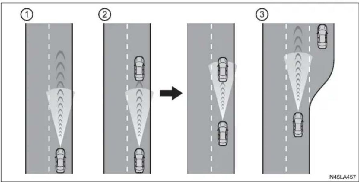
flowchart
graph TD
    A["①"] --> B["②"]
    B --> C["③"]
    style A fill:#f9f,stroke:#333
    style B fill:#bbf,stroke:#333
    style C fill:#f9f,stroke:#333
① Example of constant speed cruising
When there are no vehicles ahead
The vehicle travels at the speed set by the driver. The desired vehicle-to-vehicle distance can also be set by operating the vehicle-to-vehicle distance switch.
② Example of deceleration cruising and follow-up cruising
When a preceding vehicle driving slower than the set speed appears
When a vehicle is detected running ahead of you, the system automatically decelerates your vehicle. When a greater reduction in vehicle speed is necessary, the system applies the brakes (the stop lights will come on at this time). The system will respond to changes in the speed of the vehicle ahead in order to maintain the vehicle-to-vehicle distance set by the driver.
Approach warning warns you when the system cannot decelerate sufficiently to prevent your vehicle from closing in on the vehicle ahead.
③ Example of acceleration
When there are no longer any preceding vehicles driving slower than the set speed
The system accelerates until the set speed is reached. The system then returns to constant speed cruising.
Setting the vehicle speed (vehicle-to-vehicle distance control mode)
1 Press the "ON-OFF" button to activate the cruise control.
Radar cruise control indicator will come on and a message will be displayed on the multi-information display.
Press the button again to deactivate the cruise control.
If the "ON-OFF" button is pressed and held for 1.5 seconds or more, the system turns on in constant speed control mode. (→P. 289)
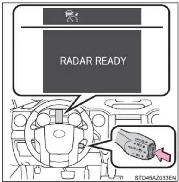
2 Accelerate or decelerate, with accelerator pedal operation, to the desired vehicle speed (at or above approximately 30 mph [50 km/h]) and push the lever down to set the speed.
Cruise control "SET" indicator will come on.
The vehicle speed at the moment the lever is released becomes the set speed.
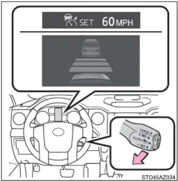
Adjusting the set speed
To change the set speed, operate the lever until the desired set speed is displayed.
① Increases the speed
② Decreases the speed
Fine adjustment: Momentarily move the lever in the desired direction.
Large adjustment: Hold the lever up or down to change the speed, and release when the desired speed is reached.
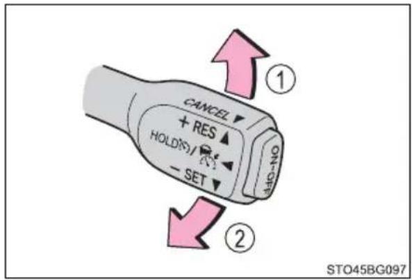
In the vehicle-to-vehicle distance control mode, the set speed will be increased or decreased as follows:
For the U.S. mainland, Hawaii
Fine adjustment: By 1 mph (1.6 km/h) ^ ^1 or 1 km/h (0.6 mph) ^ ^2 each time the lever is operated
Large adjustment: Increases or decreases in 1 mph (1.6 km/h) ^1 or 1 km/h (0.6 mph) ^2 increments for as long as the lever is held
For Canada, Guam, Saipan, Samoa and Puerto Rico
Fine adjustment: By 1 mph (1.6 km/h) ^ ^1 or 1 km/h (0.6 mph) ^ ^2 each time the lever is operated
Large adjustment: Increases or decreases in 5 mph (8 km/h) *1 or 5 km/h (3.1 mph)*2 increments for as long as the lever is held
In the constant speed control mode ( P. 289), the set speed will be increased or decreased as follows:
Fine adjustment: By 1 mph (1.6 km/h) ^ ^1 or 1 km/h (0.6 mph) ^ ^2 each time the lever is operated
Large adjustment: The speed will continue to change while the lever is held.
*1: When the set speed is shown in "MPH"
*2: When the set speed is shown in "km/h"
Changing the vehicle-to-vehicle distance (vehicle-to-vehicle distance control mode)
Pressing the switch changes the vehicle-to-vehicle distance as follows:
① Long
② Medium
③ Short
The vehicle-to-vehicle distance is set automatically to long mode when the engine switch is turned to ON.
If a vehicle is running ahead of you, the preceding vehicle mark will also be displayed.
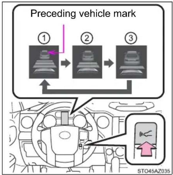
flowchart
graph TD
    A["① State"] --> B["② State"]
    B --> C["③ State"]
    D["Sto45AZ035"] --> E["Next State"]
    style A fill:#f9f,stroke:#333
    style B fill:#f9f,stroke:#333
    style C fill:#f9f,stroke:#333
    style D fill:#ccf,stroke:#333
    style E fill:#cfc,stroke:#333
Vehicle-to-vehicle distance settings (vehicle-to-vehicle distance control mode)
Select a distance from the table below. Note that the distances shown correspond to a vehicle speed of 50 mph (80 km/h). Vehicle-to-vehicle distance increases/decreases in accordance with vehicle speed.
| Distance options Vehicle-to-vehicle distance | |
| Long Approximately 1 | 60 ft. (50 m) |
| Medium Approximately | 130 ft. (40 m) |
| Short Approximately | 100 ft. (30 m) |
Canceling and resuming the speed control
① Pulling the lever toward you cancels the speed control.
The speed control is also canceled when the brake pedal is depressed.
② Pushing the lever up resumes the cruise control and returns vehicle speed to the set speed.
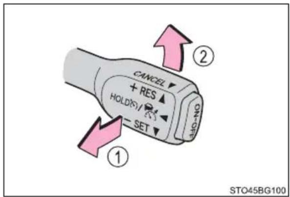
However, cruise control does not resume when the vehicle speed is approximately 25 mph (40 km/h) or less.
Approach warning (vehicle-to-vehicle distance control mode)
When your vehicle is too close to a vehicle ahead, and sufficient automatic deceleration via the cruise control is not possible, the display will flash and the buzzer will sound to alert the driver. An example of this would be if another driver cuts in front of you while you are following a vehicle. Depress the brake pedal to ensure an appropriate vehicle-to-vehicle distance.
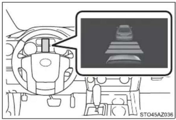
natural_image
Interior view of a car dashboard and steering wheel, with a close-up of a vehicle on display (no text or symbols visible)■Warnings may not occur when
In the following instances, warnings may not occur even when the vehicle-to-vehicle distance is small.
- When the speed of the preceding vehicle matches or exceeds your vehicle speed
●When the preceding vehicle is traveling at an extremely slow speed
●Immediately after the cruise control speed was set
●When depressing the accelerator pedal
Selecting constant speed control mode
When constant speed control mode is selected, your vehicle will maintain a set speed without controlling the vehicle-to-vehicle distance. Select this mode only when vehicle-to-vehicle distance control mode does not function correctly due to a dirty radar sensor, etc.
1 With the cruise control off, press and hold the "ON-OFF" button for 1.5 seconds or more.
Immediately after the "ON-OFF" button is pressed, the radar cruise control indicator will come on. Afterwards, it switches to the cruise control indicator.
Switching to constant speed control mode is only possible when operating the lever with the cruise control off.
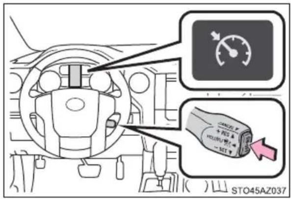
2 Accelerate or decelerate, with accelerator pedal operation, to the desired vehicle speed (at or above approximately 30 mph [50 km/h]) and push the lever down to set the speed.
Cruise control "SET" indicator will come on.
The vehicle speed at the moment the lever is released becomes the set speed.
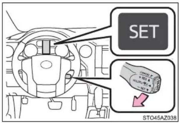
Adjusting the speed setting: →P. 286
Canceling and resuming the speed setting: →P. 288
■Dynamic radar cruise control can be set when
● The shift lever is in D or range 4 or higher of S has been selected.
●Vehicle speed is at or above approximately 30 mph (50 km/h).
■Accelerating after setting the vehicle speed
The vehicle can accelerate by operating the accelerator pedal. After accelerating, the set speed resumes. However, during vehicle-to-vehicle distance control mode, the vehicle speed may decrease below the set speed in order to maintain the distance to the preceding vehicle.
■ Automatic cancelation of vehicle-to-vehicle distance control mode
Vehicle-to-vehicle distance control mode is automatically canceled in the following situations:
● Actual vehicle speed falls at or below approximately 25 mph (40 km/h).
●VSC is activated.
●TRAC is activated for a period of time.
- When the VSC or TRAC system is turned off.
●The sensor cannot detect correctly because it is covered in some way.
●Pre-collision braking is activated.
If vehicle-to-vehicle distance control mode is automatically canceled for any other reason, there may be a malfunction in the system. Contact your Toyota dealer.
■Automatic cancelation of constant speed control mode
Constant speed control mode is automatically canceled in the following situations:
● Actual vehicle speed is more than approximately 10 mph (16 km/h) below the set vehicle speed.
● Actual vehicle speed falls below approximately 25 mph (40 km/h).
●VSC is activated.
●TRAC is activated for a period of time.
- When the VSC or TRAC system is turned off.
●Pre-collision braking is activated.
If constant speed control mode is automatically canceled for any other reason, there may be a malfunction in the system. Contact your Toyota dealer.
■Brake system operation sound
If the brakes are applied automatically while the vehicle is in vehicle-to-vehicle distance control mode, a brake system operation sound may be heard.
This does not indicate a malfunction.
■ Warning messages and buzzers for dynamic radar cruise control
Warning messages and buzzers are used to indicate a system malfunction or to inform the driver of the need for caution while driving. If a warning message is shown on the multi-information display, read the message and follow the instructions.
■ When the sensor may not be correctly detecting the vehicle ahead
In the case of the following and depending on the conditions, operate the brake pedal when deceleration of the system is insufficient or operate the accelerator pedal when acceleration is required.
As the sensor may not be able to correctly detect these types of vehicles, the approach warning ( P. 288) may not be activated.
● Vehicles that cut in suddenly
● Vehicles traveling at low speeds
● Vehicles that are not moving in the same lane
● Vehicles with small rear ends (trailers with no load on board, etc.)
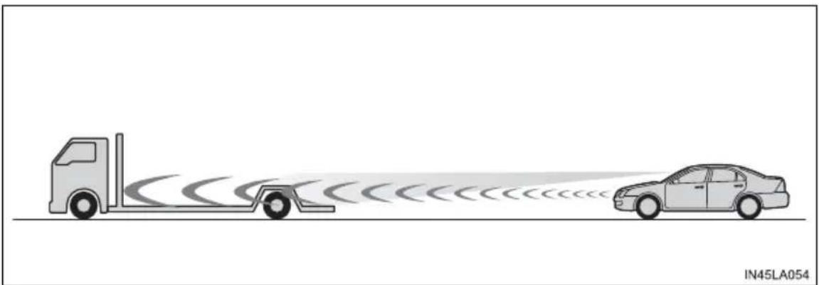
natural_image
Diagram showing two vehicles with sensor waves, one truck and one car, on a road (no text or symbols)●Motorcycles traveling in the same lane
- When water or snow thrown up by the surrounding vehicles hinders the detecting of the sensor
- When your vehicle is pointing upwards (caused by a heavy load in the luggage compartment, etc.)
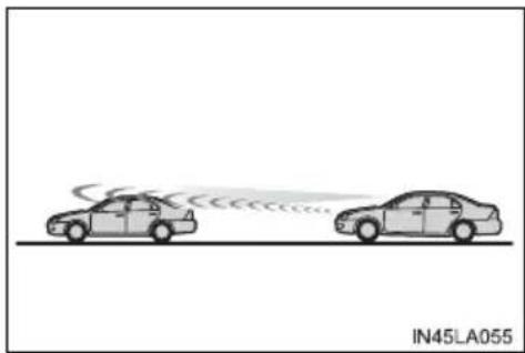
natural_image
Two cars on a road with visible sound waves, no text or symbols present●Preceding vehicle has an extremely high ground clearance
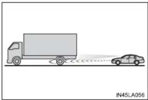
natural_image
Illustration of a truck and a car on a road with sound waves, no text or symbols presentConditions under which the vehicle-to-vehicle distance control mode may not function correctly
In the case of the following conditions, operate the brake pedal (or accelerator pedal, depending on the situation) as necessary.
As the sensor may not be able to correctly detect vehicles ahead, the system may not operate properly.
- When the road curves or when the lanes are narrow
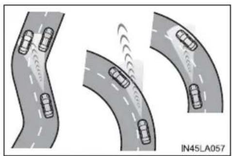
natural_image
Three curved road scenarios showing cars on different surfaces with motion indicators (no text or symbols)- When steering wheel operation or your position in the lane is unstable
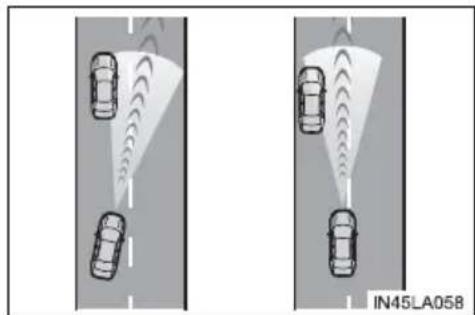
natural_image
Two identical road scenarios showing cars on a road with visible traffic flow indicators (no text or symbols)●When the vehicle ahead of you decelerates suddenly
- When driving on a road surrounded by a structure, such as in a tunnel or on a bridge
● While the vehicle speed is decreasing to the set speed after the vehicle accelerates by depressing the accelerator pedal
Cruise control\*
Summary of functions
Use the cruise control to maintain a set speed without depressing the accelerator pedal.
① Indicators
② Cruise control switch
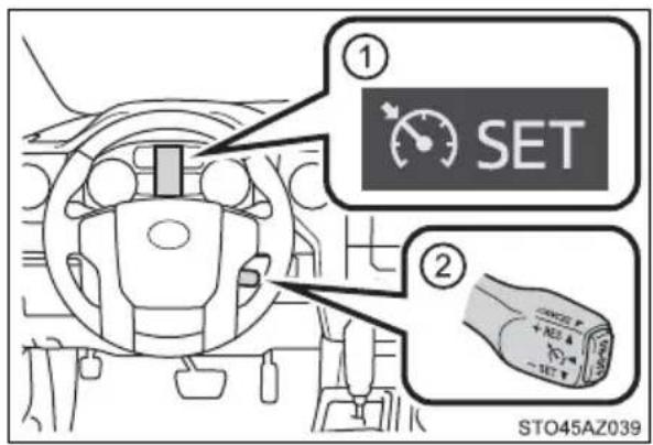
Setting the vehicle speed
1 Press the "ON-OFF" button to activate the cruise control.
Cruise control indicator will come on.
Press the button again to deactivate the cruise control.
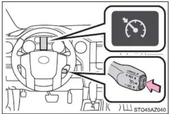
2 Accelerate or decelerate the vehicle to the desired speed, and push the lever down to set the speed.
"SET" indicator will come on.
The vehicle speed at the moment the lever is released becomes the set speed.
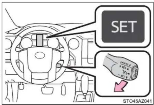
Adjusting the set speed
To change the set speed, operate the lever until the desired set speed is obtained.
① Increases the speed
② Decreases the speed
Fine adjustment: Momentarily move the lever in the desired direction.
Large adjustment: Hold the lever in the desired direction.
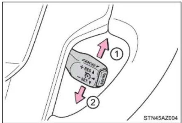
The set speed will be increased or decreased as follows:
Fine adjustment: By approximately 1 mph (1.6 km/h) each time the lever is operated.
Large adjustment: The set speed can be increased or decreased continually until the lever is released.
Canceling and resuming the constant speed control
① Pulling the lever toward you cancels the constant speed control.
The speed setting is also canceled when the brakes are applied.
② Pushing the lever up resumes the constant speed control.
Resuming is available when the vehicle speed is more than approximately 25 mph (40 km/h).
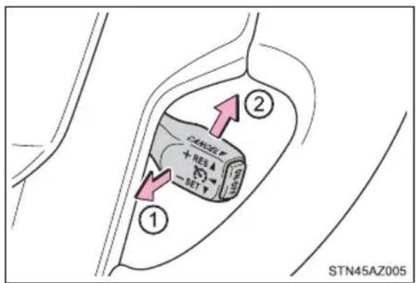
Cruise control can be set when
● The shift lever is in D or range 4 or higher of S has been selected.
●Vehicle speed is above approximately 25 mph (40 km/h).
■Accelerating after setting the vehicle speed
● The vehicle can be accelerated normally. After acceleration, the set speed resumes.
● Even without canceling the cruise control, the set speed can be increased by first accelerating the vehicle to the desired speed and then pushing the lever down to set the new speed.
■Automatic cruise control cancelation
Cruise control will stop maintaining the vehicle speed in any of the following situations.
● Actual vehicle speed falls more than approximately 10 mph (16 km/h) below the preset vehicle speed.
At this time, the memorized set speed is not retained.
●Actual vehicle speed is below approximately 25 mph (40 km/h).
●VSC is activated.
●TRAC is activated for a period of time.
- When the VSC or TRAC system is turned off.
● 4WD models: The operation cannot be switched for 5 seconds or more after operating the front-wheel drive control switch.
If “Cruise Control Malfunction Visit Your Dealer” is displayed on the multi-information display
Press the "ON-OFF" button once to deactivate the system, and then press the button again to reactivate the system.
If the cruise control speed cannot be set or if the cruise control cancels immediately after being activated, there may be a malfunction in the cruise control system. Have the vehicle inspected by your Toyota dealer.

WARNING
■To avoid operating the cruise control by mistake
Switch the cruise control off using the "ON-OFF" button when not in use.
■Situations unsuitable for cruise control
Do not use cruise control in any of the following situations.
Doing so may result in loss of control and could cause an accident resulting in death or serious injury.
In heavy traffic
● On roads with sharp bends
● On winding roads
● On slippery roads, such as those covered with rain, ice or snow
On steep hills
Vehicle speed may exceed the set speed when driving down a steep hill.
●When your vehicle is towing a trailer or during emergency towing
Intuitive parking assist\*
The distance from your vehicle to nearby obstacles when parallel parking or maneuvering into a garage is measured by the sensors and communicated via the multi-information display and buzzer. Always check the surrounding area when using this system.
■Types of sensors
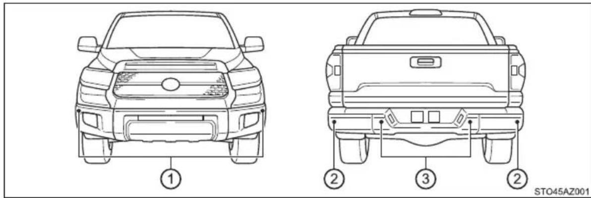
① Front corner sensors
② Rear corner sensors
③ Rear center sensors
■Intuitive parking assist switch
Turns the intuitive parking assist on/off
When on, the indicator light comes on to inform the driver that the system is operational.
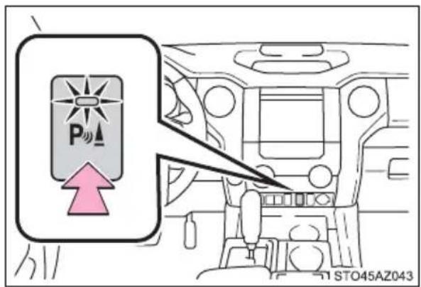
The distance display and buzzer
When the sensor detects an obstacle, the direction of and the approximate distance to the obstacle are displayed and the buzzer sounds.
■Intuitive parking assist display
① Front corner sensor operation
② Rear corner sensor operation
③ Rear center sensor operation
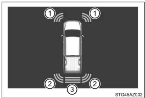
■Sensor operation and distance to an obstacle
The system operates when the vehicle approaches an obstacle, as shown by the following table.
When 2 or more obstacles are detected simultaneously, the buzzer system responds to the nearest zone.
▶ Front corner sensors
| Approximate distance to obstacle Display and buzzer | |
| 2.0 ft. (60 cm) to 1.5 ft. (45 cm) Intermittent | |
| 1.5 ft. (45 cm) to 1.0 ft. (30 cm) Fast Intermittent | |
| Less than 1.0 ft. (30 cm) Continuously |
▶ Rear corner sensors
| Approximate distance to obstacle Display and buzzer | |
| 2.8 ft. (85 cm) to 2.0 ft. (60 cm) Intermittent | |
| 2.0 ft. (60 cm) to 1.3 ft. (40 cm) Fast intermittent | |
| Less than 1.3 ft. (40 cm) Continuously |
▶ Rear center sensor
| Approximate distance to obstacle Display and buzzer | |
| 5.9 ft. (180 cm) to 3.3 ft. (100 cm) Intermittent | |
| 3.3 ft. (100 cm) to 2.5 ft. (75 cm) Fast intermittent | |
| 2.5 ft. (75 cm) to 1.6 ft. (50 cm) | Very fast intermittent |
| Less than 1.6 ft. (50 cm) | Continuously |
■ When multiple obstacles are detected in front and behind the vehicle at the same time
The buzzer will change in the following manner.
- If an obstacle has been detected within 1.5 ft. (45 cm) of the front or 2.8 ft. (85 cm) in rear of the vehicle (a continuous buzzer is sounding), and a new obstacle is detected at the other end of the vehicle, the buzzer will sound 7 times then 1 continuous buzzer.
- If an obstacle has been detected within 1.5 ft. (45 cm) of the front or 2.8 ft. (85 cm) in rear of the vehicle (a continuous buzzer is sounding), and a new obstacle is detected in the same way at the other end of the vehicle, the buzzer will sound 3 times then 1 continuous buzzer.
■Detection range of the sensors
① Approximately 5.9 ft. (180 cm)
② Approximately 2.0 ft. (60 cm)
③ Approximately 2.8 ft. (85 cm)
The diagram shows the detection range of the sensors. Note that the sensors may not be able to detect obstacles that are extremely close to the vehicle.
The range of the sensors may change depending on the shape of the object, etc.
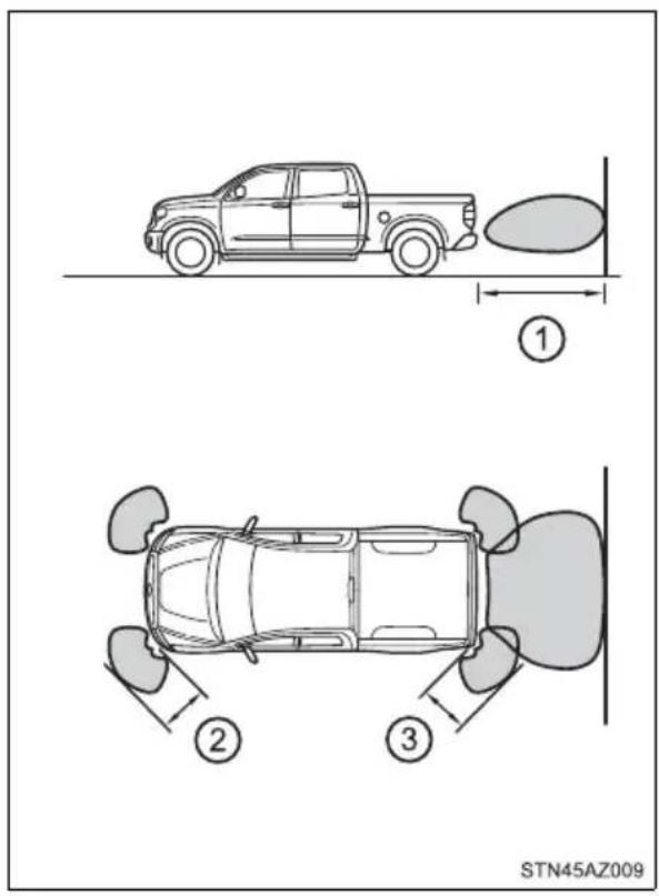
■The intuitive parking assist can be operated when
●Front corner sensors:
• The engine switch is in ON.
• The shift lever is in R.
- The shift lever is not in P or R and vehicle speed is less than about 6 mph (10 km/h).
●Rear corner and rear center sensors:
• The engine switch is in ON.
• The shift lever is in R.
If the display flashes and a message is displayed
→P. 494, 495
■Certification (Canada only)
This ISM device complies with Canadian ICES-001.

WARNING
■When using the intuitive parking assist
Observe the following precautions.
Failure to do so may result in the vehicle being unable to be driven safely and possibly cause an accident.
- Do not use the sensor at speeds in excess of 6 mph (10 km/h).
The sensors' detection areas and reaction times are limited. When moving forward or reversing, check the areas surrounding the vehicle (especially the sides of the vehicle) for safety, and drive slowly, using the brake control the vehicle's speed. - Do not install accessories within the sensors' detection areas.

WARNING
■Sensor detection information
Pay particular attention to the following instances in where this may occur. Failing to do so way result in the vehicle being unable to be driven or parked safety and possibly cause an accident.
The sensor's detection areas are limited to the areas around the vehicle's front corner and rear bumpers.
● Certain vehicle conditions and the surrounding environment may affect the ability of the sensor to correctly detect obstacles. Particular instances where this may occur are listed below.
- There is dirt, snow or ice on the sensor. (Wiping the sensors will resolve this problem.)
- The sensor is frozen. (Thawing the area will resolve this problem.)
- The sensor is covered in any way.
- The vehicle is leaning considerably to one side.
- On an extremely bumpy road, on an incline, on gravel, or on grass.
- The vicinity of the vehicle is noisy due to vehicle horns, motorcycle engines, air brakes of large vehicles, or other loud noises producing ultrasonic waves.
- There is another vehicle equipped with parking assist sensors in the vicinity.
- The sensor is coated with a sheet of spray or heavy rain.
- The vehicle is equipped with a fender pole or radio antenna.
- The bumper or sensor receives a strong impact.
- The vehicle is approaching a tall or curved curb.
- In harsh sunlight or intense cold weather.
- The area directly under the bumpers is not detected.
- If obstacles draw too close to the sensor.
- A non-genuine Toyota suspension (lowered suspension, etc.) is installed.
- A backlit license plate, license plate holder, etc., are installed.
- People may not be detected if they are wearing certain types and coloring of clothing.
- People, animals, and moving objects may not be able to be detected. In addition to the examples above, there are instances in which, because of their shape, signs and other objects may be judged by the sensor to be closer than they are.

WARNING
● The shape of the obstacle may prevent the sensor from detecting it. Pay particular attention to the following obstacles:
- Wires, fences, ropes, etc.
- Cotton, snow and other materials that absorb sound waves
- Sharply-angled objects
- Low obstacles
- Tall obstacles with upper sections projecting outwards in the direction of your vehicle
●The following situations may occur during use.
- Depending on the shape of the obstacle and other factors, the detection distance may shorten, or detection may be impossible.
- Obstacles may not be detected if they are too close to the sensor.
- There will be a short delay between obstacle detection and display. Even at slow speeds, there is a possibility that the obstacle will come within the sensor's detection areas before the display is shown and the warning beep sounds.
- Thin posts or objects lower than the sensor may not be detected for collision when approached, even if they have been detected once.
- It might be difficult to hear beeps due to the volume of audio system or air flow noise of air conditioning system.

NOTICE
■When using intuitive parking assist-sensor
In the following situations, the system may not function correctly due to a sensor malfunction, etc. Have the vehicle checked by your Toyota dealer.
● A beep does not sound when you turn the main switch on.
●The intuitive parking assist operation display flashes, and a beep sounds when no obstacles are detected.
- If the area around a sensor collides with something, or is subjected to strong impact.
- If the bumper collides with something.
- If the display shows continuously without a beep.
- If a display error occurs, first check the sensor.
If the error occurs even if there is no ice, snow or mud on the sensor, it is likely that the sensor is malfunctioning.
Notes when washing the vehicle
Do not apply intensive bursts of water or steam to the sensor area. Doing so may result in the sensor malfunctioning.
BSM (Blind Spot Monitor)\*
Summary of the Blind Spot Monitor
The Blind Spot Monitor is a system that has 2 functions;
●The Blind Spot Monitor function
Assists the driver in making the decision when changing lanes
●The Rear Cross Traffic Alert function
Assists the driver when backing up
These functions use same sensors.
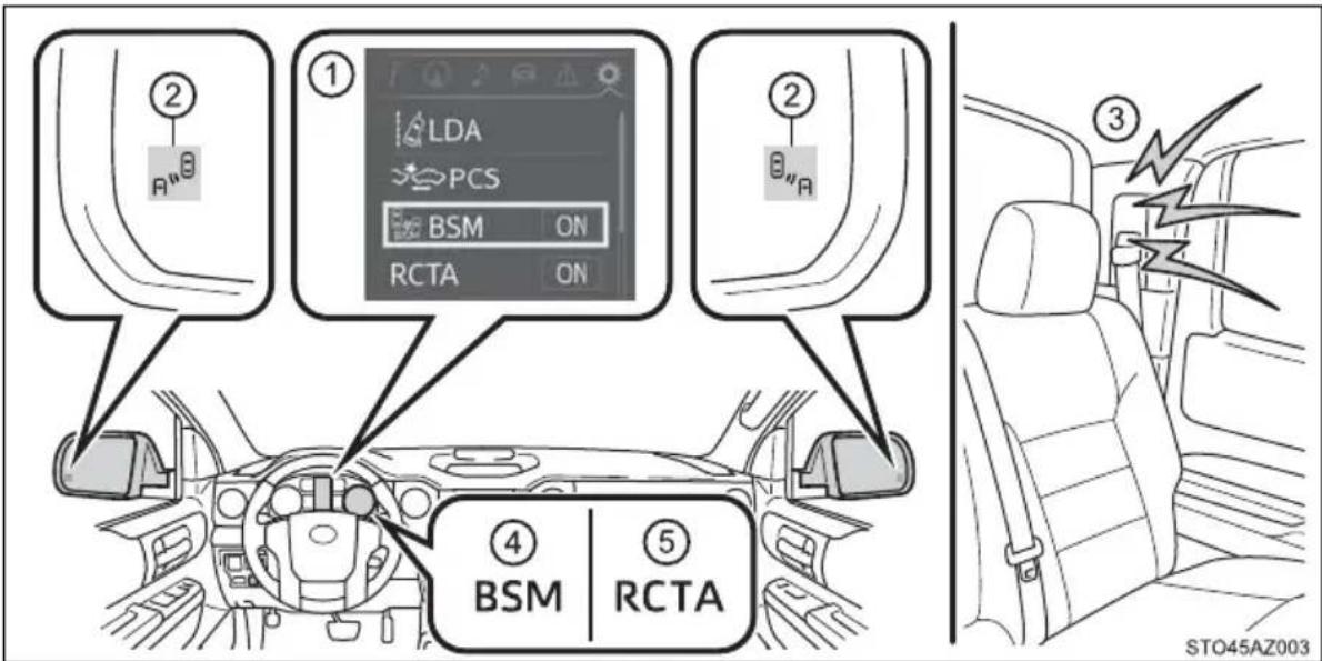
① Multi-information display
Turning the BSM function/RCTA function on/off. ( P. 306)
② Outside rear view mirror indicators
Blind Spot Monitor function:
When a vehicle is detected in a blind spot of the outside rear view mirrors or approaching rapidly from behind into a blind spot, the outside rear view mirror indicator on the detected side will illuminate. If the turn signal lever is operated toward the detected side, the outside rear view mirror indicator will flash.
Rear Cross Traffic Alert function:
When a vehicle approaching from the right or left at the rear of the vehicle is detected, both outside rear view mirror indicators will flash.
③ Rear Cross Traffic Alert buzzer (Rear Cross Traffic Alert function only)
When a vehicle approaching from the right or left rear of the vehicle is detected, a buzzer sounds from behind the left-hand rear pillar.
④ “BSM” indicator
When the BSM function is turned on, the indicator illuminates.
⑤ "RCTA" indicator
When the RCTA function is turned on, the indicator illuminates.
Turning the BSM function/RCTA function on/off
The BSM (Blind Spot Monitor) function and RCTA (Rear Cross Traffic Alert) function can be enabled/disabled on the multi-information display as following:
1 Press "<" or "> " of meter control switches and select ⚙.
2 Press “^” or “v” of meter control switches and select “BSM” or “RCTA”, and press to select the desired setting (on/off).
Changing the BSM indicator brightness
The BSM (Blind Spot Monitor) outside rear view mirror indicators brightness can be changed on the multi-information display as following:
1 Press "<" or "> " of meter control switches and select
2 Press “^” or “v” of meter control switches and select “Vehicle Settings”, and then press .
3 Press “^” or “v” of meter control switches and select “BSM Brightness”, and then press □ to select the desired setting (bright/dim).
Changing the Rear Cross Traffic Alert warning buzzer volume
1 Press "<" or "> " of meter control switches and select ⚙️.
2 Press “^” or “v” of meter control switches and select “Vehicle Settings”, and then press .
3 Press “ ” or “v” of meter control switches and select “RCTA Volume”, and then press to select the desired setting.
The buzzer volume changes with each press.
■The outside rear view mirror indicators visibility
When under strong sunlight, the outside rear view mirror indicator may be difficult to see.
■Rear Cross Traffic Alert buzzer hearing
Rear Cross Traffic Alert function may be difficult to hear over noises such as high audio volume.
■ When there is a malfunction in the Blind Spot Monitor system
If a system malfunction is detected due to any of the following reasons, warning messages will be displayed: (→P. 494, 495)
●There is a malfunction with the sensors
●The sensors have become dirty
●The outside temperature is extremely high or low
●The sensor voltage has become abnormal
■Certification for the Blind Spot Monitor system
For vehicles sold in the U.S.A.
FCC ID: OAYSRR3A
This device complies with part 15 of the FCC Rules. Operation is subject to the following three conditions:
(1) This device may not cause harmful interference, and
(2) this device must accept any interference received, including interference that may cause undesired operation.
FCC Warning
Changes or modifications not expressly approved by the party responsible for compliance could void the user's authority to operate the equipment.
For vehicles sold in Canada
Applicable law: Canada 310
This device complies with Industry Canada licence-exempt RSS standard(s). Operation is subject to the following two conditions: (1) this device may not cause interference, and (2) this device must accept any interference, including interference that may cause undesired operation of the device.
Frequency bands: 24.05 – 24.25 GHz
Output power: less than 20 milliwatts

WARNING
■Handling the radar sensor
One Blind Spot Monitor sensor installed inside the left and right side of the vehicle rear bumper respectively. Observe the following to ensure the Blind Spot Monitor system can function correctly.
- Keep the sensor and its surrounding area on the bumper clean at all times.
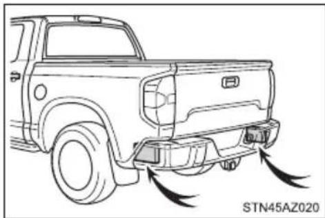
natural_image
Line drawing of a pickup truck showing side bumper and exhaust lines (no text or symbols)- Do not subject the sensor or surrounding area on the bumper to a strong impact. If the sensor moves even slightly off position, the system may malfunction and vehicles that enter the detection area may not be detected. If the sensor or surrounding area is subject to a strong impact, always have the area inspected by your Toyota dealer.
- Do not disassemble the sensor.
- Do not attach accessories or stickers to the sensor or surrounding area on the bumper.
●Do not modify the sensor or surrounding area on the bumper. - Do not paint the rear bumper any color other than an official Toyota color.
The Blind Spot Monitor function
The Blind Spot Monitor function uses radar sensors to detect vehicles that are traveling in an adjacent lane in the area that is not reflected in the outside rear view mirror (the blind spot), and advises the driver of the vehicles existence via the outside rear view mirror indicator.
The Blind Spot Monitor function detection areas
The areas that vehicles can be detected in are outlined below.
The range of the detection area extends to:
① Approximately 11.5 ft. (3.5 m) from the side of the vehicle
The first 1.6 ft. (0.5 m) from the side of the vehicle is not in the detection area
② Approximately 9.8 ft. (3 m) from the rear bumper
③ Approximately 3.3 ft. (1 m) forward of the rear bumper
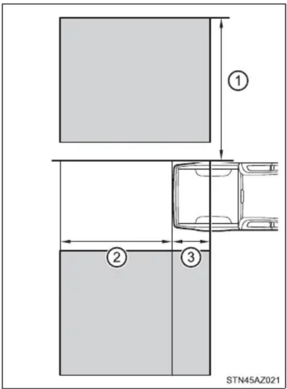

WARNING
■ Cautions regarding the use of the system
The driver is solely responsible for safe driving. Always drive safely, taking care to observe your surroundings.
The Blind Spot Monitor function is a supplementary function which alerts the driver that a vehicle is present in the blind spot. Do not overly rely on the Blind Spot Monitor function. The function cannot judge if it is safe to change lanes, therefore over reliance could cause an accident resulting in death or serious injury.
According to conditions, the system may not function correctly. Therefore the driver's own visual confirmation of safety is necessary.
■The Blind Spot Monitor function is operational when
●The BSM function is set to on.
●Vehicle speed is greater than approximately 25 mph (40 km/h).
■The Blind Spot Monitor function will detect a vehicle when
●A vehicle in an adjacent lane overtakes the vehicle.
● Another vehicle enters the detection area when it changes lanes.
●You overtake a vehicle in adjacent lane.
■ Conditions under which the Blind Spot Monitor function will not detect a vehicle
The Blind Spot Monitor function is not designed to detect the following types of vehicles and/or objects:
● Small motorcycles, bicycles, pedestrians, etc. *
● Vehicles traveling in the opposite direction
● Guardrails, walls, signs, parked vehicles and similar stationary objects *
- Following vehicles that are in the same lane*
● Vehicles driving 2 lanes across from your vehicle*
● Vehicles which are being overtaken rapidly by your vehicle.
*: Depending on conditions, detection of a vehicle and/or object may occur
Conditions under which the Blind Spot Monitor function may not function correctly
● The Blind Spot Monitor function may not detect vehicles correctly in the following conditions:
- During bad weather such as heavy rain, fog, snow, etc.
- When ice or mud, etc., is attached to the rear bumper
- When driving on a road surface that is wet due to rain, standing water, etc.
- When there is a significant difference in speed between your vehicle and the vehicle that enters the detection area
- When a vehicle is in the detection area from a stop and remains in the detection area as your vehicle accelerates
- When driving up or down consecutive steep inclines, such as hills, a dip in the road, etc.
- When multiple vehicles approach with only a small gap between each vehicle
- When vehicle lanes are wide, and the vehicle in the next lane is too far away from your vehicle
- When the vehicle that enters the detection area is traveling at about the same speed as your vehicle
- When towing anything such as trailer, boat, etc.
- When there is a significant difference in height between your vehicle and the vehicle that enters the detection area
- Directly after the BSM function is set to on
- When towing a trailer
- When items such as a bicycle carrier are installed on the rear of the vehicle
- Instances of the Blind Spot Monitor function unnecessarily detecting a vehicle and/or object may increase under the following conditions:
- When there is only a short distance between your vehicle and a guardrail, wall, etc.
- When there is only a short distance between your vehicle and a following vehicle
- When vehicle lanes are narrow and a vehicle driving 2 lanes across from your vehicle enters the detection area
- When items such as a bicycle carrier are installed on the rear of the vehicle
The Rear Cross Traffic Alert function
The Rear Cross Traffic Alert functions when your vehicle is in reverse. It can detect other vehicles approaching from the right or left rear of the vehicle. It uses radar sensors to alert the driver of the other vehicle's existence through flashing the outside rear view mirror indicators and sounding a buzzer.
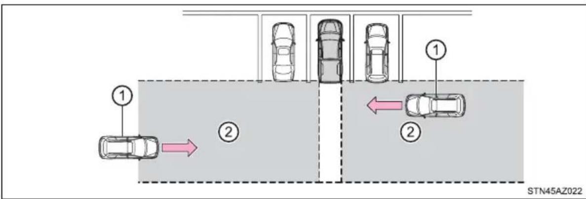
flowchart
graph TD
    A["1"] --> B["2"]
    B --> C["3"]
    C --> D["4"]
    D --> E["5"]
    E --> F["6"]
    F --> G["7"]
    G --> H["8"]
    H --> I["9"]
    I --> J["10"]
    style A fill:#f9f,stroke:#333
    style B fill:#ccf,stroke:#333
    style C fill:#cfc,stroke:#333
    style D fill:#fcc,stroke:#333
    style E fill:#cff,stroke:#333
    style F fill:#ffc,stroke:#333
    style G fill:#cfc,stroke:#333
    style H fill:#fcc,stroke:#333
    style I fill:#ffc,stroke:#333
    style J fill:#cfc,stroke:#333
① Approaching vehicles Detection areas

WARNING
■ Cautions regarding the use of the system
The driver is solely responsible for safe driving. Always drive safely, taking care to observe your surroundings.
The Rear Cross Traffic Alert function is only an assist and is not a replacement for careful driving. Driver must be careful when backing up, even when using Rear Cross Traffic Alert function. The driver's own visual confirmation of behind you and your vehicle is necessary and be sure there are no pedestrians, other vehicles, etc., before backing up. Failure to do so could cause death or serious injury.
According to conditions, the system may not function correctly. Therefore the driver's own visual confirmation of safety is necessary.
The Rear Cross Traffic Alert function detection areas
The areas that vehicles can be detected in are outlined below.
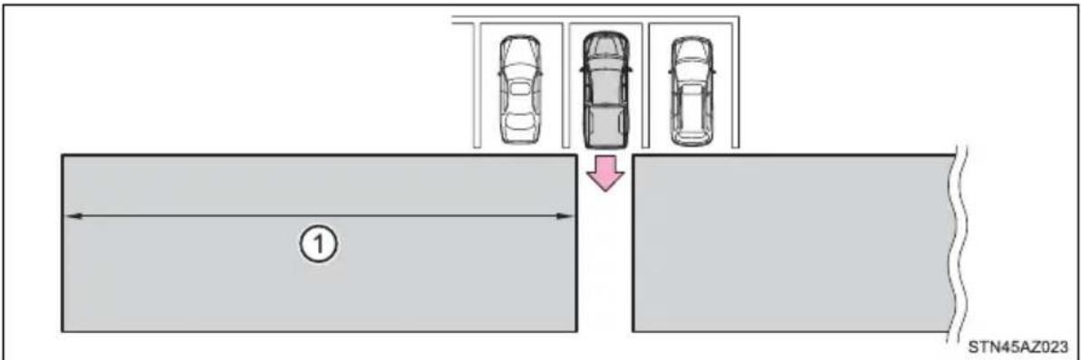
To give the driver a more consistent time to react, the buzzer can alert for faster vehicles from farther away.
Example:
| Approaching vehicle Speed | 1 Approximate alert distance |
| Fast 18 mph (28 km/h) 65 ft. (20 m) | |
| Slow 5 mph (8 km/h) 18 ft. (5.5 m) |
■The Rear Cross Traffic Alert function is operational when
●The RCTA function is set to on.
●The shift lever is in R.
● Vehicle speed is less than approximately 5 mph (8 km/h).
● Approaching vehicle speed is between approximately 5 mph (8 km/h) and 18 mph (28 km/h).
■ Conditions under which the Rear Cross Traffic Alert function will not detect a vehicle
The Rear Cross Traffic Alert function is not designed to detect the following types of vehicles and/or objects.
● Small motorcycles, bicycles, pedestrians, etc. *
● Vehicles approaching from directly behind
● Guardrails, walls, signs, parked vehicles and similar stationary objects*
● Vehicles moving away from your vehicle
●Vehicles approaching from the parking spaces next to your vehicle*
● Vehicles backing up in the parking space next to your vehicle*
*: Depending on conditions, detection of a vehicle and/or object may occur.
■ Conditions under which the Rear Cross Traffic Alert function may not function correctly
The Rear Cross Traffic Alert function may not detect vehicles correctly in the following conditions.
- When ice or mud, etc., is attached to the rear bumper
●During bad weather such as heavy rain, fog, snow, etc.
●When multiple vehicles approach continuously
●Shallow angle parking
●When a vehicle is approaching at high speed - When parking on a steep incline, such as hills, a dip in the road, etc.
●Directly after the RCTA function is set to on
● Directly after the engine is started with the RCTA function is on
●When towing a trailer
● Vehicles that the sensors cannot detect because of obstacles
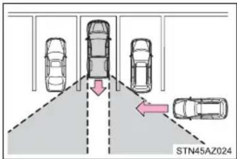
Four-wheel drive system\*
Summary of functions
Use the front-wheel drive control switch to select the following transfer modes:
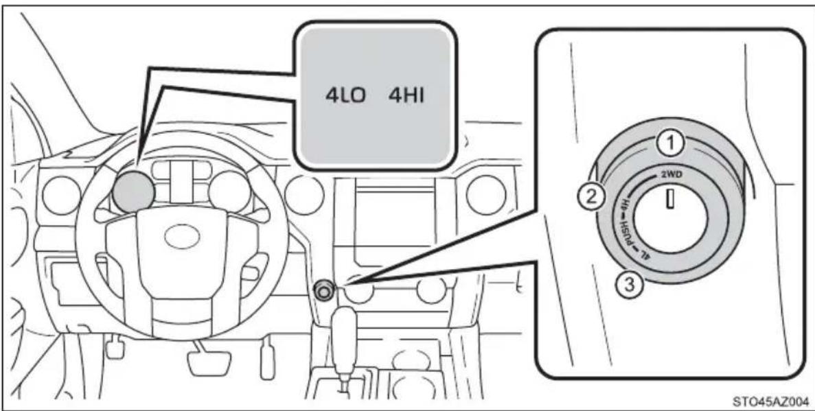
① “2WD” (high speed position, two-wheel drive)
Use this for normal driving on dry hard-surfaced roads. This position gives greater economy, quietest ride and least wear.
② “4H” (high speed position, four-wheel drive)
Use this for driving only on tracks that permit the tires slide, like off-road, icy or snow-covered roads. This position provides greater traction than two-wheel drive.
The "4HI" indicator will come on.
③ “4L” (low speed position, four-wheel drive)
Use this for maximum power and traction. Use "4L" for climbing or descending steep hills, off-road driving, and hard pulling in sand, mud or deep snow.
The "4LO" indicator will come on.
Shifting between "2WD" and "4H"
■Shifting from “2WD” to “4H”
1 Reduce vehicle speed to less than 62 mph (100 km/h).
2 Turn the front-wheel drive control switch to "4H". The "4HI" indicator will come on.
■ Shifting from “4H” to “2WD”
1 Reduce vehicle speed to less than 62 mph (100 km/h).
2 Turn the front-wheel drive control switch to "2WD".
The "4HI" indicator will go off.
Shifting between "4H" and "4L"
■ Shifting from "4H" to "4L"
1 Stop the vehicle completely and continue to depress the brake pedal.
2 Shift the shift lever to N.
3 Push and turn the front-wheel drive control switch to "4L".
The "4LO" indicator will come on.
■ Shifting from “4L” to “4H”
1 Stop the vehicle completely and continue to depress the brake pedal.
2 Shift the shift lever to N.
3 Push and turn the front-wheel drive control switch to "4H".
The "4LO" indicator will go off.
When the front-wheel drive control switch is shifted to "4L"
VSC is automatically turned off.
If the "4HI" indicator flashes
The transfer mode may not successfully change. Drive straight ahead while accelerating or decelerating, or drive in reverse.
If the "4LO" indicator continues to flash
The transfer mode may not successfully change. Operate the front-wheel drive control switch again.
If the "4LO" indicator continues to flash and a buzzer sounds
The shift lever is not in N and/or the vehicle is moving. Stop the vehicle completely, shift the shift lever to N and make sure that the indicator stops flashing.
If the "4HI" or "4LO" indicator flashes rapidly
There may be a malfunction in the four-wheel drive system. Have the vehicle inspected by your Toyota dealer immediately.
■Four-wheel drive usage frequency
You should drive in four-wheel drive for at least 10 miles (16 km) each month. This will assure that the front drive components are lubricated.

WARNING
■ Shifting the front-wheel drive control switch from “2WD” to “4H” while driving
Never operate the front-wheel drive control switch if the wheels are slipping. Stop the slipping or spinning before shifting.
■When the vehicle is parked
If the shift lever is moved before the "4LO" indicator turns on/off, the transfer mode may not be shifted completely. The transfer mode disengages both the front and rear driveshafts from the powertrain and allows the vehicle to move regardless of the shift position. (At this time, the indicator blinks and the buzzer sounds.)
Therefore, the vehicle is free to roll even if the automatic transmission is in P. You or someone else could be seriously injured. You must complete the shifting of the transfer mode before placing transmission in P.
AUTO LSD system
The AUTO LSD system aids traction by using the traction control system to control engine performance and braking when one of the drive wheels begins to spin.
The system should be used only when one of the drive wheels spinning occurs in a ditch or rough surface.
System operation
The system can be used on 2WD models and in 2WD mode on 4WD models. The system is activated when driving at a speed under 62 mph (100 km/h). The AUTO LSD system will be activated with the following two procedures.
Press the briefly to turn on the system.
The "AUTO LSD" indicator will come on.
To turn off the system, press again.

Stop the vehicle completely, and
press for more than 3 seconds.
The "AUTO LSD" and VSC off indicators will come on.
To turn off the system, press again.

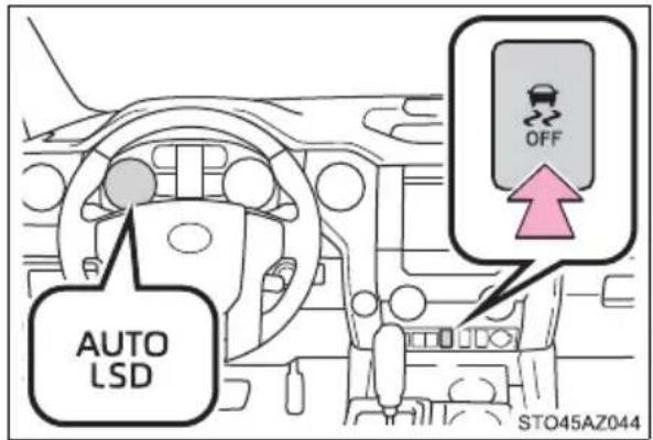
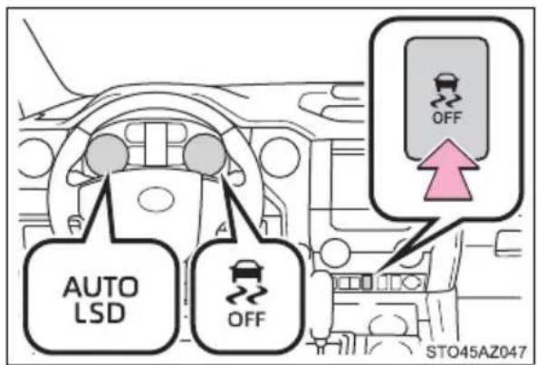
■If the brake system overheats
The system will cease operation and a buzzer will alert the driver. At this time, the “TRAC OFF” indicator will come on. Stop the vehicle in a safe place. (There is no problem with continuing normal driving.) The system will be automatically restored after a short time.

WARNING
■To avoid an accident
Failure to do so, a much greater steering effort and more careful cornering control will be required.
- Do not use the AUTO LSD system in conditions other than when one of the drive wheels spinning occurs in a ditch or rough surface.
●Do not drive with the AUTO LSD system continuously turned on.

NOTICE
■Activating while driving
Do not activate the AUTO LSD system if the wheel is slipping. Stop the slipping or spinning before activating.
Driving assist systems
To keep driving safety and performance, the following systems operate automatically in response to various driving situations. Be aware, however, that these systems are supplementary and should not be relied upon too heavily when operating the vehicle.
◆ABS (Anti-lock Brake System)
Helps to prevent wheel lock when the brakes are applied suddenly, or if the brakes are applied while driving on a slippery road surface
Brake assist
Generates an increased level of braking force after the brake pedal is depressed when the system detects a panic stop situation
◆VSC (Vehicle Stability Control)
Helps the driver to control skidding when swerving suddenly or turning on slippery road surfaces
◆Trailer Sway Control
Helps the driver to control trailer sway by selectively applying brake pressure for individual wheels and reducing driving torque when trailer sway is detected
◆TRAC (Traction Control) for 2WD models and 2WD mode on 4WD models
Helps to maintain drive power and prevent the drive wheels from spinning when starting the vehicle or accelerating on slippery roads
◆Hill-start assist control
Helps to reduce the backward movement of the vehicle when starting on an uphill
When the TRAC/VSC/Trailer Sway Control systems are operating
The slip indicator light will flash while the TRAC/VSC/Trailer Sway Control systems are operating.
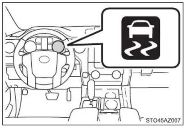
Disabling the TRAC systems
If the vehicle gets stuck in mud, dirt or snow, the TRAC system may reduce power from the engine to the wheels. Pressing to turn the system off may make it easier for you to rock the vehicle in order to free it.
■Turning off TRAC system
▶ 2WD models and 2WD mode on 4WD models
To turn the TRAC system off,
press

The "AUTO LSD" indicator light will come on.
Press again to turn the
system back on.
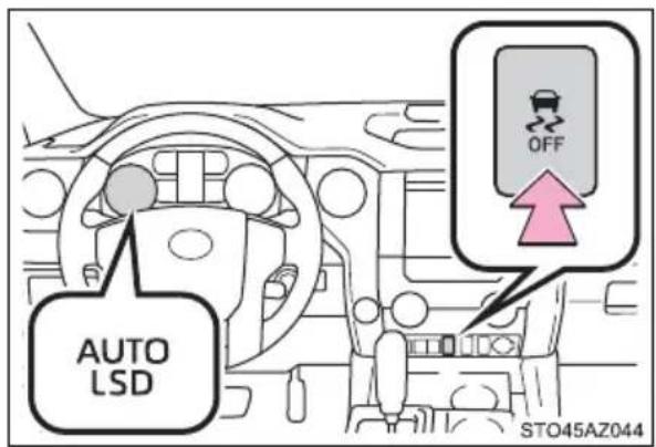
▶ 4H mode on 4WD models
To turn the TRAC system off,
press

The "TRAC OFF" indicator light will come on.
Press

ain to turn the
system back on.
▶ 4L mode on 4WD models
To turn the TRAC system off,
press and hold

more
than 3 seconds while the vehicle is stopped.
The VSC off and "TRAC OFF" indicator light will come on.
Press

ain to turn the
system back on.
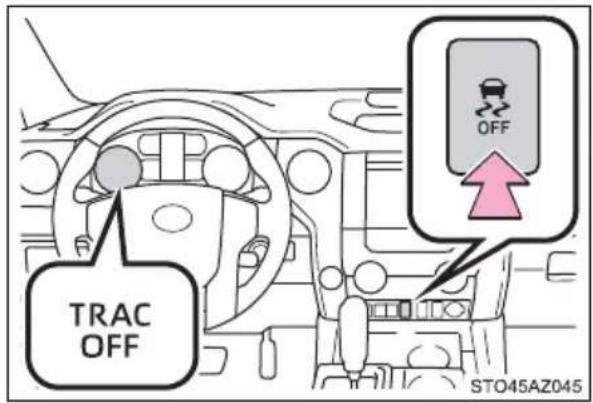
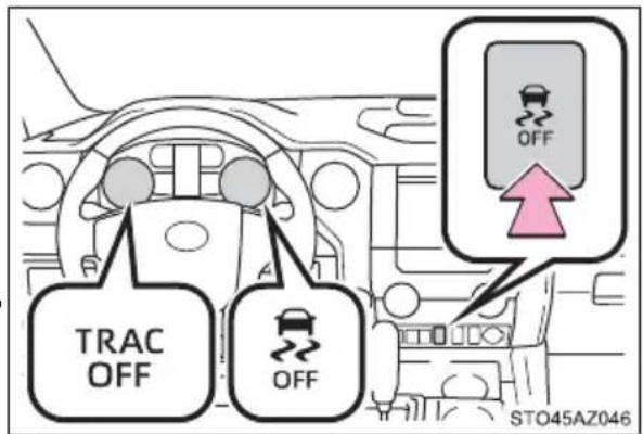
■Turning off TRAC, VSC and Trailer Sway Control systems
▶ 2WD models and 2WD mode on 4WD models
To turn the TRAC, VSC and Trailer Sway Control systems off, stop the vehi-
cle completely, and then press and hold OFF for more than 3 seconds while the AUTO LSD system is activated. (→P. 318)
▶ 4H mode on 4WD models
To turn the TRAC, VSC and Trailer Sway Control systems off, press and
hold

for more than 3 seconds while the vehicle is stopped.
The VSC off and "TRAC OFF" indicator light will come on.
Press

again to turn the system back on.
When the VSC or TRAC system is turned off by pressing the VSC off switch
On vehicles with pre-collision system, pre-collision brake assist and pre-collision braking will also be disabled. The PCS warning light will come on and the message will be shown on the multi-information display. (→P. 500)
- When the “TRAC OFF” indicator light comes on even if VSC off switch has not been pressed.
TRAC cannot be operated. Contact your Toyota dealer.
■Operating conditions of hill-start assist control
When the following four conditions are met, the hill-start assist control will operate:
● The shift lever is in a position other than P or N (when starting off forward/backward on an upward incline)
●The vehicle is stopped
●The accelerator pedal is not depressed
●The parking brake is not engaged
■Automatic system cancelation of hill-start assist control
The hill-start assist control will turn off in any of the following situations:
The shift lever is shifted to P or N
●The accelerator pedal is depressed
●The parking brake is engaged
●2 seconds at maximum elapsed after the brake pedal is released
■ Sounds and vibrations caused by the ABS, brake assist, VSC, TRAC, Trailer Sway Control and hill-start assist control systems
●A sound may be heard from the engine compartment when the brake pedal is depressed repeatedly, when the engine is started or just after the vehicle begins to move. This sound does not indicate that a malfunction has occurred in any of these systems.
● Any of the following conditions may occur when the above systems are operating. None of these indicates that a malfunction has occurred.
- Vibrations may be felt through the vehicle body and steering.
- A motor sound may be heard also after the vehicle comes to a stop.
- The brake pedal may pulsate slightly after the ABS is activated.
- The brake pedal may move down slightly after the ABS is activated.
■Automatic reactivation of TRAC, Trailer Sway Control and VSC systems
After turning the TRAC, Trailer Sway Control and VSC systems off, the systems will be automatically re-enabled in the following situations:
- When the engine switch is turned off
- If only the TRAC system is turned off, the TRAC will turn on when vehicle speed increases
If both the TRAC and VSC systems are turned off, automatic re-enabling will not occur when vehicle speed increases.
■If the brake system overheats
TRAC will cease operation, and the slip indicator will change from flashing to being on continuously to alert the driver. Stop the vehicle in a safe place. (There is no problem with continuing normal driving.)
■Shifting to "4L"
VSC and Trailer Sway Control are automatically turned off.

WARNING
■The ABS does not operate effectively when
● The limits of tire gripping performance have been exceeded (such as excessively worn tires on a snow covered road).
● The vehicle hydroplanes while driving at high speed on wet or slick roads.
■ Stopping distance when the ABS is operating may exceed that of normal conditions
The ABS is not designed to shorten the vehicle's stopping distance. Always maintain a safe distance from the vehicle in front of you, especially in the following situations:
- When driving on dirt, gravel or snow-covered roads
●When driving with tire chains - When driving over bumps in the road
- When driving over roads with potholes or uneven surfaces
■TRAC/VSC may not operate effectively when
Directional control and power may not be achievable while driving on slippery road surfaces, even if the TRAC/VSC system is operating.
Drive the vehicle carefully in conditions where stability and power may be lost.
■Hill-start assist control does not operate effectively when
- Do not overly rely on hill-start assist control. Hill-start assist control may not operate effectively on steep inclines and roads covered with ice.
● Unlike the parking brake, hill-start assist control is not intended to hold the vehicle stationary for an extended period of time. Do not attempt to use hill-start assist control to hold the vehicle on an incline, as doing so may lead to an accident.
■When the TRAC/VSC/Trailer Sway Control are activated
The slip indicator light flashes. Always drive carefully. Reckless driving may cause an accident. Exercise particular care when the indicator light flashes.

WARNING
■When the TRAC/VSC/Trailer Sway Control systems are turned off
Be especially careful and drive at a speed appropriate to the road conditions. As these are the systems to help ensure vehicle stability and driving force, do not turn the TRAC/VSC/Trailer Sway Control systems off unless necessary.
Trailer Sway Control is part of the VSC system and will not operate if VSC is turned off or experiences a malfunction.
■Replacing tires
Make sure that all tires are of the specified size, brand, tread pattern and total load capacity. In addition, make sure that the tires are inflated to the recommended tire inflation pressure level.
The ABS, TRAC, VSC and Trailer Sway Control systems will not function correctly if different tires are installed on the vehicle.
Contact your Toyota dealer for further information when replacing tires or wheels.
■Handling of tires and the suspension
Using tires with any kind of problem or modifying the suspension will affect the driving assist systems, and may cause a system to malfunction.
■Trailer Sway Control precaution
The Trailer Sway Control system is not able to reduce trailer sway in all situations. Depending on many factors such as the conditions of the vehicle, trailer, road surface, and driving environment, the Trailer Sway Control system may not be effective. Refer to your trailer owner's manual for information on how to tow your trailer properly.
■If trailer sway occurs
Observe the following precautions.
Failure to do so may cause death or serious injury.
● Firmly grip the steering wheel. Steer straight ahead.
Do not try to control trailer swaying by turning the steering wheel.
- Begin releasing the accelerator pedal immediately but very gradually to reduce speed.
Do not increase speed. Do not apply vehicle brakes.
If you make no extreme correction with the steering or brakes, your vehicle and trailer should stabilize. (→P. 213)
Trailer brake controller\*
Summary of functions
The trailer brakes can be controlled by the Trailer brake controller via the 7-pin connector. By selecting the type of brakes that are being used on the trailer (electric or electric-over-hydraulic) and setting the gain for the controller, the manual TRAILER BRAKE OUTPUT slider is used to slow just the trailer. The vehicle brake pedal will also slow down as well as stop the trailer when applied, also via the same connector. Gain values, manual brake outputs, trailer brake types, a the trailer connection status are displayed in the multi-information display.
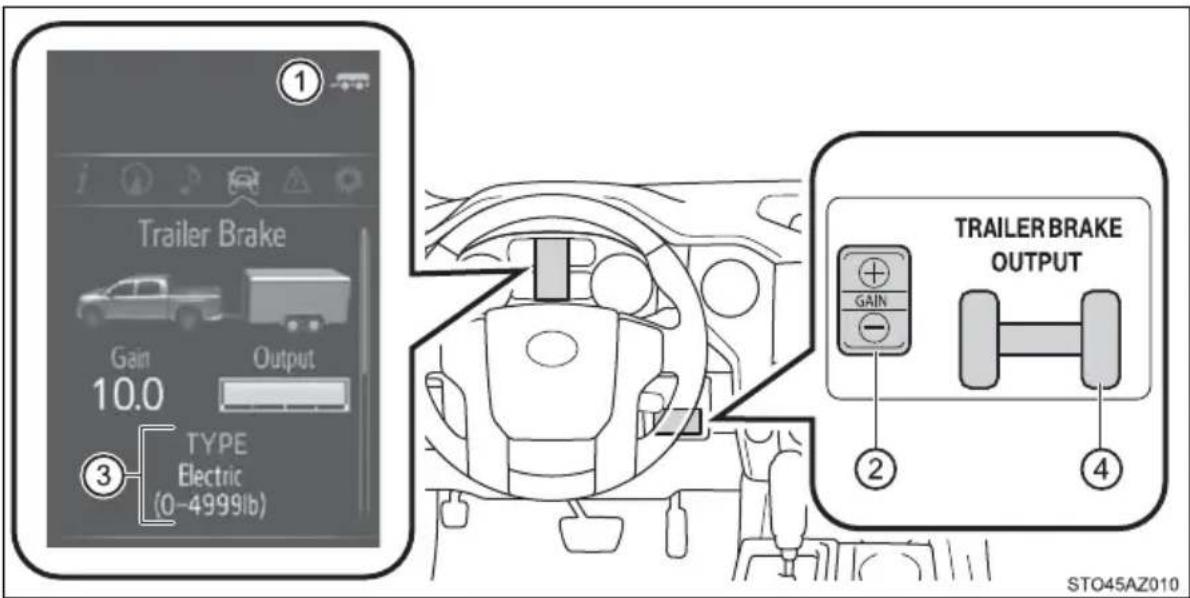
① Trailer connection indicator
When the trailer has been connected, the indicator comes on green.
② GAIN (+/-) selection button
Pressing the GAIN (+/-) buttons will adjust the amount of power that can be outputted to the trailer brakes. The gain can be adjusted from 0 (no trailer braking) to 10 (maximum output) in 0.5 increments. Each press of the button will increase or decrease the gain setting by one step. The gain value will appear in the multi-information display.
③ Trailer brake type
Trailer brake type can be selected by using the multi-information. The combination meter will show which trailer brake type is selected in the multi-information display.
④ Manual TRAILER BRAKE OUTPUT slider
Adjusting this slider position will engage the trailer's brakes only. If the manual TRAILER BRAKE OUTPUT slider is used while the vehicle brake is applied, the greater of the two outputs will be sent to the trailer brakes.
Changing settings of the trailer brake type
The trailer brake type can be selected on the multi-information display as following:
1 Press "<" or "> " of meter control switches and select
2 Press “^” or “v” of meter control switches and select “Vehicle Settings”, and press
3 Press “ ” or “v” of meter control switches and select “TBC Trailer Type”, and press to select the correct type of trailer brakes that are equipped on the trailer.
Changing trailer brake type will cause the current gain setting to reset to zero. Make sure to set the gain as described in the following section.
Setting the Gain
Gain setting on trailer brake controller should be set for a specific towing condition. Gain setting should be adjusted each time the vehicle load, trailer load, road conditions, or weather changes. Setting the gain value to 0 will disable the trailer brake controller output.
1 Make sure the trailer brakes are in good working condition and functioning normally. See trailer dealer if necessary.
2 Hook up the trailer and make proper electrical connections.
3 Select the correct type of trailer brakes that are equipped on the trailer by using the multi-information display.
4 Drive vehicle with trailer attached on a level road surface similar to towing condition and in traffic-free environment. Driving speed should be approximately 20 - 25 mph [35 - 40 km/h].
5 Using the GAIN (+/-) selection buttons, set a starting gain of 5.0.
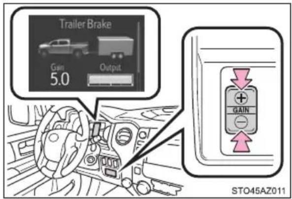
6 While driving 20 - 25 mph [35 - 40 km/h], fully apply the manual TRAILER BRAKE OUTPUT slider.
7 Adjust the gain setting, using the GAIN (+/-) selection buttons, to either increase or decrease to just below the point of trailer wheel lock-up.
867For confirmation, repeat steps and until desired gain setting is reached (just below point of trailer wheel lock-up).
■When using the trailer brake control system
Please turn off the intuitive parking assist while towing a trailer. If left on, sonar sensors will detect the trailer being towed.
■When setting the gain
Wheel lock-up occurs when the trailer wheel squeals or tire smoke occurs. Trailer wheels may not lock-up while driving heavily loaded trailer. During this case, adjust the Trailer gain to the highest allowable setting for the towing condition.
■When disconnecting and reconnecting battery terminals
The gain setting data will be reset.

WARNING
■Trailer brake type setting
It is the responsibility of the driver to make sure the trailer brakes are functioning normally and adjusted appropriately. Failure to check and maintain trailer brakes may result in loss of vehicle control, crash, or serious injury. Trailer brake control system will work with most electric and electric-over-hydraulic trailer braking systems up to 3 axles (24A output to trailer brakes). Please be sure to test compatibility with the system at low speeds and in a safe area. If a warning message appears in the multi-information display (→P. 500), have the vehicle inspected by your Toyota dealer immediately. Some electric-over-hydraulic trailer brakes will take some minimum output to activate. Trailer brake control system will not work with trailer hydraulic surge brakes.
■When driving on slippery road surfaces
When stopping with ABS activated, output to the trailer might be reduced in order to reduce the likelihood of trailer wheels to lock. The trailer is not equipped with ABS. Drive safely on slippery road surfaces.
Winter driving tips
Carry out the necessary preparations and inspections before driving the vehicle in winter. Always drive the vehicle in a manner appropriate to the prevailing weather conditions.
Preparation for winter
- Use fluids that are appropriate to the prevailing outside temperatures.
- Engine oil
- Engine coolant
- Washer fluid
●Have a service technician inspect the condition of the battery.
● Have the vehicle fitted with four snow tires or purchase a set of tire chains for the rear tires.
Ensure that all tires are the same size and brand, and that chains match the size of the tires.
Before driving the vehicle
Perform the following according to the driving conditions:
- Do not try to forcibly open a window or move a wiper that is frozen. Pour warm water over the frozen area to melt the ice. Wipe away the water immediately to prevent it from freezing.
● To ensure proper operation of the climate control system fan, remove any snow that has accumulated on the air inlet vents in front of the windshield. - Check for and remove any excess ice or snow that may have accumulated on the exterior lights, vehicle's roof, chassis, around the tires or on the brakes.
- Remove any snow or mud from the bottom of your shoes before getting in the vehicle.
When driving the vehicle
Accelerate the vehicle slowly, keep a safe distance between you and the vehicle ahead, and drive at a reduced speed suitable to road conditions.
When parking the vehicle
●Park the vehicle and move the shift lever to P without setting parking brake. The parking brake may freeze up, preventing it from being released. If the vehicle is parked without setting the parking brake, make sure to block the wheels.
Failure to do so may be dangerous because it may cause the vehicle to move unexpectedly, possibly leading to an accident.
- If the vehicle is parked without setting the parking brake, confirm that the shift lever cannot be moved out of P^* .
*: The shift lever will be locked if it is attempted to be shifted from P to any other position without depressing the brake pedal. If the shift lever can be shifted from P, there may be a problem with the shift lock system. Have the vehicle inspected by your Toyota dealer immediately.
Selecting tire chains
Use the correct tire chain size when mounting the tire chains.
Chain size is regulated for each tire size.
① Side chain
(0.2 in. [5 mm] in diameter)
② Cross chain (0.25 in. [6.3 mm] in diameter)
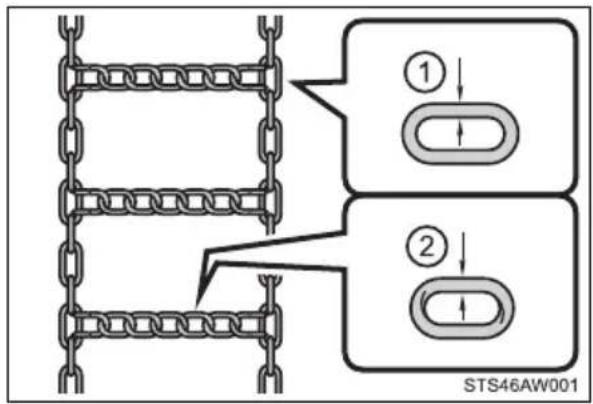
Regulations on the use of tire chains
Regulations regarding the use of tire chains vary depending on location and type of road. Always check local regulations before installing chains.
■Tire chain installation
Observe the following precautions when installing and removing chains:
● Install and remove tire chains in a safe location.
● Install tire chains on the rear tires. Do not install tire chains on the front tires.
● Install tire chains on rear tires as tightly as possible. Retighten chains after driving 1/4 — 1/2 mile (0.5 — 1.0 km).
● Install tire chains following the instructions provided with the tire chains.

WARNING
■Driving with snow tires
Observe the following precautions to reduce the risk of accidents.
Failure to do so may result in a loss of vehicle control and cause death or serious injury.
● Use tires of the specified size.
●Maintain the recommended level of air pressure.
- Do not drive in excess of 75 mph (120 km/h), regardless of the type of snow tires being used.
● Use snow tires on all, not just some wheels.
- 4WD models: Do not mix tires of different makes, models, tread patterns or treadwear.
■Driving with tire chains
Observe the following precautions to reduce the risk of accidents.
Failure to do so may result in the vehicle being unable to be driven safely, and may cause death or serious injury.
- Do not drive in excess of the speed limit specified for the tire chains being used, or 30 mph (50 km/h), whichever is lower.
● Avoid driving on bumpy road surfaces or over potholes. - Avoid sudden acceleration, abrupt steering, sudden braking and shifting operations that cause sudden engine braking.
- Slow down sufficiently before entering a curve to ensure that vehicle control is maintained.

NOTICE
■Repairing or replacing snow tires
Request repairs or replacement of snow tires from Toyota dealers or legitimate tire retailers.
This is because the removal and attachment of snow tires affects the operation of the tire pressure warning valves and transmitters.
■Fitting tire chains
The tire pressure warning valves and transmitters may not function correctly when tire chains are fitted.
Off-road precautions
This vehicle belongs to the utility vehicle class, which has higher ground clearance and narrower tread in relation to the height of its center of gravity to make it capable of performing in a wide variety of off-road applications.
Off-road vehicle features
● Specific design characteristics give it a higher center of gravity than ordinary passenger cars. This vehicle design feature causes this type of vehicle to be more likely to rollover. And, utility vehicles have a significantly higher rollover rate than other types of vehicles.
● An advantage of the higher ground clearance is a better view of the road allowing you to anticipate problems.
- It is not designed for cornering at the same speeds as ordinary passenger cars any more than low-slung sports cars are designed to perform satisfactorily under off-road conditions. Therefore, sharp turns at excessive speeds may cause the vehicle to rollover.

WARNING
■Off-road vehicle precautions
Always observe the following precautions to minimize the risk of death, serious injury or damage to your vehicle:
- In a rollover crash, an unbelted person is significantly more likely to die than a person wearing a seat belt. Therefore, the driver and all passengers should always fasten their seat belts.
●Avoid sharp turns or abrupt maneuvers, if at all possible.
Failure to operate this vehicle correctly may result in loss of control or vehicle rollover causing death or serious injury. - Avoid loading any items on the roof that will raise the vehicle's center of gravity.
●Always slow down in gusty crosswinds. Because of its profile and higher center of gravity, your vehicle is more sensitive to side winds than an ordinary passenger car. Slowing down will allow you to have better control. - When driving off-road or in rugged terrain, do not drive at excessive speeds, jump, make sharp turns, strike objects, etc. This may cause loss of control or vehicle rollover causing death or serious injury. You are also risking expensive damage to your vehicle's suspension and chassis.
- Do not drive horizontally across steep slopes. Driving straight up or straight down is preferred. Your vehicle (or any similar off-road vehicle) can tip over sideways much more easily than forward or backward.
Off-road driving
When driving your vehicle off-road, please observe the following precautions to ensure your driving enjoyment and to help prevent the closure of areas to off-road vehicles.
- Drive your vehicle only in areas where off-road vehicles are permitted to travel.
- Respect private property. Get owner's permission before entering private property.
- Do not enter areas that are closed. Honor gates, barriers and signs that restrict travel.
- Stay on established roads. When conditions are wet, driving techniques should be changed or travel delayed to prevent damage to roads.
■Additional information for off-road driving
For owners in U.S. mainland, Hawaii and Puerto Rico:
To obtain additional information pertaining to driving your vehicle off-road, consult the following organizations.
●State and Local Parks and Recreation Departments
●State Motor Vehicle Bureau
●Recreational Vehicle Clubs
●U.S. Forest Service and Bureau of Land Management

WARNING
■Off-road driving precautions
Always observe the following precautions to minimize the risk of death, serious injury or damage to your vehicle:
- Drive carefully when off the road. Do not take unnecessary risks by driving in dangerous places.
- Do not grip the steering wheel spokes when driving off-road. A bad bump could jerk the wheel and injure your hands. Keep both hands and especially your thumbs on the outside of the rim.
● Always check your brakes for effectiveness immediately after driving in sand, mud, water or snow.
● After driving through tall grass, mud, rock, sand, rivers, etc., check that there is no grass, bush, paper, rags, stone, sand, etc., adhering or trapped on the underbody. Clear off any such matter from the underbody. If the vehicle is used with these materials trapped or adhering to the underbody, a breakdown or fire could occur.
In a rollover crash, an unbelted person is significantly more likely to die than a person wearing a seat belt. Therefore, the driver and all passengers should fasten their seat belts whenever the vehicle is moving. - When driving off-road or in rugged terrain, do not drive at excessive speeds, jump, make sharp turns, strike objects, etc. This may cause loss of control or vehicle rollover causing death or serious injury. You are also risking expensive damage to your vehicle's suspension and chassis.

NOTICE
■To prevent the water damage
Take all necessary safety measures to ensure that water damage to the engine or other components does not occur.
● Water entering the engine air intake will cause severe engine damage.
● Water entering the automatic transmission will cause deterioration in shift quality, locking up of your transmission accompanied by vibration, and ultimately damage.
Water can wash the grease from wheel bearings, causing rusting and premature failure, and may also enter the differentials, transmission and transfer case, reducing the gear oil's lubricating qualities.
■When you drive through water
If driving through water, such as when crossing shallow streams, first check the depth of the water and the bottom of the river bed for firmness. Drive slowly and avoid deep water.
■Inspection after off-road driving
- Sand and mud that has accumulated in brake drums and around brake discs may affect braking efficiency and may damage brake system components.
● Always perform a maintenance inspection after each day of off-road driving that has taken you through rough terrain, sand, mud, or water. For scheduled maintenance information, refer to the “Scheduled Maintenance Guide” or “Owner’s Manual Supplement”.
Interior features
5
5-1. Using the air conditioning system
Manual air conditioning system.... 340
Automatic air conditioning system.... 347
Seat heaters/ seat ventilators.... 354
5-2. Using the interior lights
Interior lights list 357
- Personal/interior lights main switch 357
- Personal/interior lights 358
- Cargo lamp main switch.... 359
5-3. Using the storage features
List of storage features ..... 360
- Glove box.... 362
- Console box (front separated type seat)..... 363
- Card holder...... 364
- Map holder (front bench type seat) ...... 366
- Pen holder 367
• Tissue pocket...... 368
• Overhead console...... 369
• Cup holders 370
- Bottle holders.... 372
- Auxiliary boxes (front bench type seat) ...... 373
- Storage box 375
Luggage compartment features...... 377
5-4. Using the other interior features
Other interior features ..... 378
• Sun visors...... 378
• Vanity mirrors...... 378
• Power outlets...... 379
• USB charging ports..... 382
• Armrest 383
Air conditioning controls
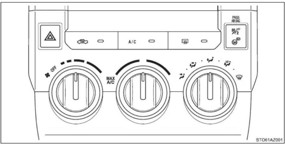
■Adjusting the temperature setting
To adjust the temperature setting, turn the temperature control dial clockwise (warm) or counterclockwise (cool).
If is not pressed, the system will blow ambient temperature air or heated air. For quick cooling, turn the temperature control dial to the "MAX A/C" position.
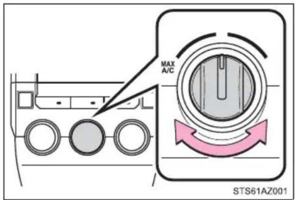
The air conditioning will automatically turn on and the air intake selector will be set to recirculated air mode.
■Fan speed setting
To adjust the fan speed, turn the fan speed control dial clockwise (increase) or counterclockwise (decrease).
Turning the dial to "OFF" turns off the fan.
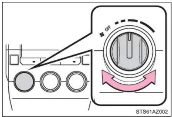
■ Change the airflow mode
To select the airflow, set the air outlet selector dial to the desired position.
The positions between the air outlet selections can also be selected for more delicate adjustment.
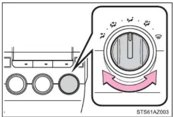
■ Other functions
- Switching between outside air and recirculated air modes (→P. 342)
● Defogging the windshield ( P. 342)
● Defogging the back window (CrewMax models) (→P. 342)
● Defogging the outside rear view mirrors (if equipped) (→P. 342)
● Windshield wiper de-icer (if equipped) (→P. 343)
Other functions
■Switching between outside air and recirculated air modes
Press .
The mode switches between outside air mode (introduces air from outside the vehicle) (indicator off) and recirculated air mode (recycles air inside the vehicle) (indicator on) each time the button is pressed.
■Defogging the windshield
Defoggers are used to defog the windshield and front side windows.
Set the air outlet selector dial to position.
Set the outside/recirculated air mode button to outside air mode if the recirculated air mode is used. (It may switch automatically.)
To defog the windshield and the side windows early, turn the air flow and temperature up.
■ Defogging the back window (CrewMax models)
Defogger is used to defog the back window.
Press .
The defogger will automatically turn off after approximately 15 minutes.
■ Defogging the outside rear view mirrors (if equipped)
Defogger is used to defog to remove raindrops, dew and frost from the outside rear view mirrors.
Press on.
The defogger will automatically turn off after approximately 15 minutes. CrewMax models: Turning the back window defogger on will turn the outside rear view mirror defoggers on.
■Windshield wiper de-icer (if equipped)
This feature is used to prevent ice from building up on the wind-shield and wiper blades.
Press on.
The defogger will automatically turn off after approximately 15 minutes.
Double Cab models: Turning the outside rear view mirror defoggers on will turn the windshield wiper de-icer on.
CrewMax models: Turning the back window defogger on will turn the wind-shield wiper de-icer on.
Air outlets
■ Location of air outlets
Air outlets and air volume changes according to the selected airflow mode.

*: CrewMax models
■ Adjusting the position and opening and closing the air outlets
Front
Direct air flow to the left or right, up or down.
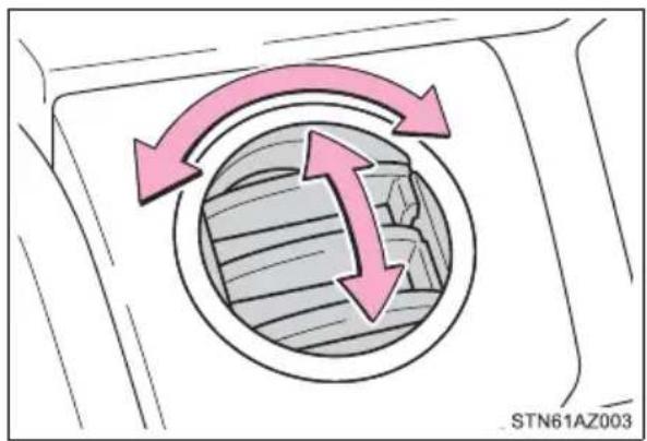
natural_image
Diagram showing a circular component with two pink arrows indicating clockwise rotation, no text or symbols present.① Open the vent
② Close the vent
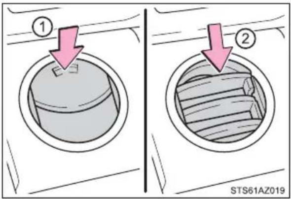
▶ Rear (CrewMax models)
① Direct air flow to the left or right, up or down.
② Turn the knob to open or close the vent.
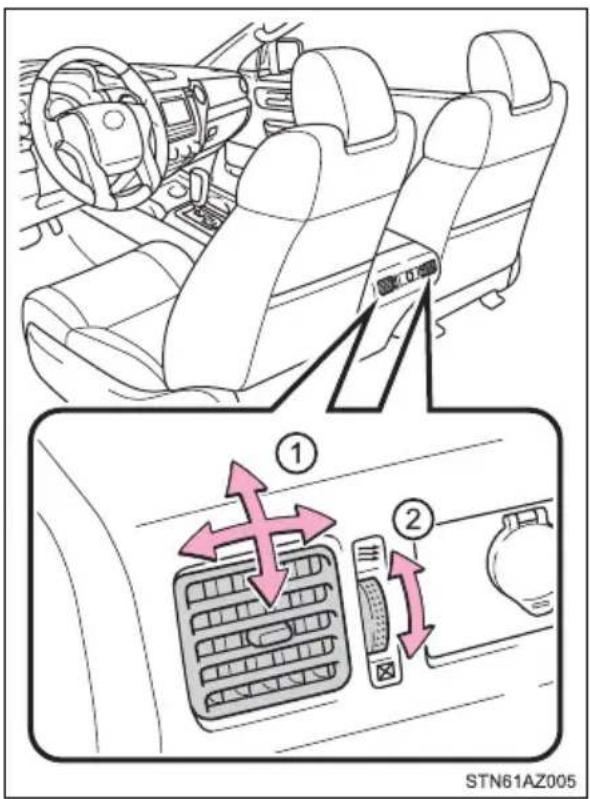
■Fogging up of the windows
● The windows will easily fog up when the humidity in the vehicle is high.
Turning on will dehumidify the air from the outlets and defog the windshield effectively.
●If you turn off, the windows may fog up more easily.
●The windows may fog up if the recirculated air mode is used.
■When driving on dusty roads
Close all windows. If dust thrown up by the vehicle is still drawn into the vehicle after closing the windows, it is recommended that the air intake mode be set to outside air mode and the fan speed to any setting except off.
■Outside/recirculated air mode
Setting to the recirculated air mode temporarily is recommended in preventing dirty air from entering the vehicle interior and helping to cool the vehicle when the outside air temperature is high.
When the outside temperature exceeds 75^ F ( 24^ C) and air conditioning system is on
- In order to reduce the air conditioning power consumption, the air conditioning system may switch to recirculated air mode automatically. This may also reduce fuel consumption.
● Recirculated air mode is selected as a default mode when the engine switch is in ON. - It is possible to switch to outside air mode at any time by pressing
■ When the outside temperature falls to nearly 32^ F ( 0^ C)
The dehumidification function may not operate even when is pressed.
■Ventilation and air conditioning odors
● To let fresh air in, set the air conditioning system to the outside air mode.
● During use, various odors from inside and outside the vehicle may enter into and accumulate in the air conditioning system. This may then cause odor to be emitted from the vents.
● To reduce potential odors from occurring:
It is recommended that the air conditioning system be set to outside air mode prior to turning the vehicle off.
Air conditioning filter
→P. 448

WARNING
■To prevent the windshield from fogging up
- Do not use during cool air operation in extremely humid weather. The difference between the temperature of the outside air and that of the windshield can cause the outer surface of the windshield to fog up, blocking your vision.
- Do not place anything on the instrument panel which may cover the air outlets. Otherwise, air flow may be obstructed, preventing the windshield defoggers to defog.
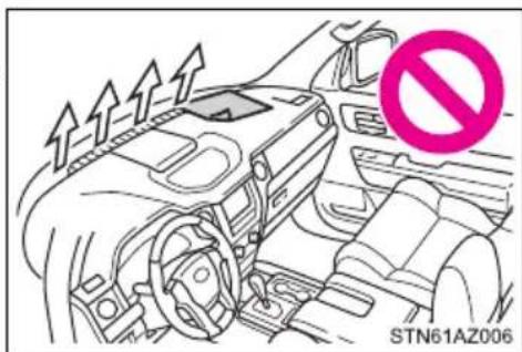
■ To prevent burns (vehicles with rear view mirror defoggers and wind-shield wiper de-icer)
- Do not touch the rear view mirror surfaces when the outside rear view mirror defoggers are on.
- Do not touch the glass at lower part of the windshield or to the side of the front pillars, when the windshield wiper de-icer is on.

NOTICE
■To prevent battery discharge
Do not leave the air conditioning system on longer than necessary when the engine is stopped.
Automatic air conditioning system\*
Air outlets and fan speed are automatically adjusted according to the temperature setting.
Air conditioning controls
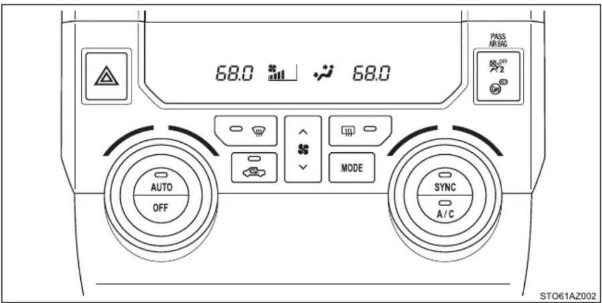
■Adjusting the temperature setting
To adjust the temperature setting, turn the temperature control dial clockwise (warm) or counterclockwise (cool).
If is not pressed, the system will blow ambient temperature air or heated air.
The air conditioning system switches between individual and simultaneous mode each time
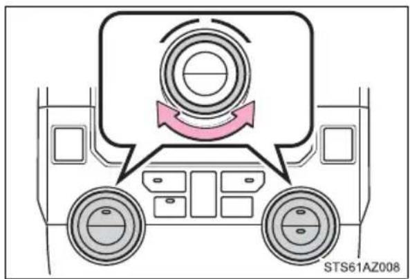
is pressed. ( P. 348)
■ Fan speed setting
To adjust the fan speed, press “^” on to increase the fan speed and “v” to decrease the fan speed. Press to turn the fan off.
*: If equipped
■Change the airflow mode
To change the airflow, press .MODE
Air outlets are adjusted each time the button is pressed.
■ Other functions
- Switching between outside air and recirculated air modes (→P. 349)
● Defogging the windshield ( P. 349)
● Defogging the back window (CrewMax models) ( P. 349)
● Defogging the outside rear view mirrors (if equipped) (→P. 349)
● Windshield wiper de-icer (if equipped) ( P. 350)
Using by automatic mode
1 Press
2 Adjust the temperature setting.
3 To stop the operation, press
■Automatic mode indicator
If the fan speed setting or air flow modes are operated, the automatic mode indicator goes off. However, automatic mode for functions other than that operated are maintained.
■Adjusting the temperature for driver and passenger seats separately (“SYNC” mode)
The air conditioning system switches between individual and simultaneous mode each time is pressed.
Simultaneous mode (the indicator on is on):
The driver's side temperature control dial can be used to adjust the temperature for driver's and front passenger's side. At this time, operate the front passenger's side temperature control dial to enter individual mode.
Individual mode (the indicator on is off):
The temperature for the driver's and front passenger's side can be adjusted separately.
Other functions
■Switching between outside air and recirculated air modes
Press
The mode switches between outside air mode (introduces air from outside the vehicle) (indicator off) and recirculated air mode (recycles air inside the vehicle) (indicator on) each time the button is pressed.
■Defogging the windshield
Defoggers are used to defog the windshield and front side windows.
Press
Set the outside/recirculated air mode button to outside air mode if the recirculated air mode is used. (It may switch automatically.) To defog the windshield and the side windows early, turn the air flow and temperature up.
To return to the previous mode, press again when the windshield is defogged.
■ Defogging the back window (CrewMax models)
Defogger is used to defog the back window.
Press
The defogger will automatically turn off after approximately 15 minutes.
■ Defogging the outside rear view mirrors (if equipped)
Defogger is used to defog to remove raindrops, dew and frost from the outside rear view mirrors.
Press
The defogger will automatically turn off after approximately 15 minutes.
CrewMax models: Turning the back window defogger on will turn the outside rear view mirror defoggers on.
■Windshield wiper de-icer (if equipped)
This feature is used to prevent ice from building up on the wind-shield and wiper blades.
Press or
The defogger will automatically turn off after approximately 15 minutes.
Double Cab models: Turning the outside rear view mirror defoggers on will turn the windshield wiper de-icer on.
CrewMax models: Turning the back window defogger on will turn the wind-shield wiper de-icer on.
Air outlets
■ Location of air outlets
Air outlets and air volume changes according to the selected airflow mode.
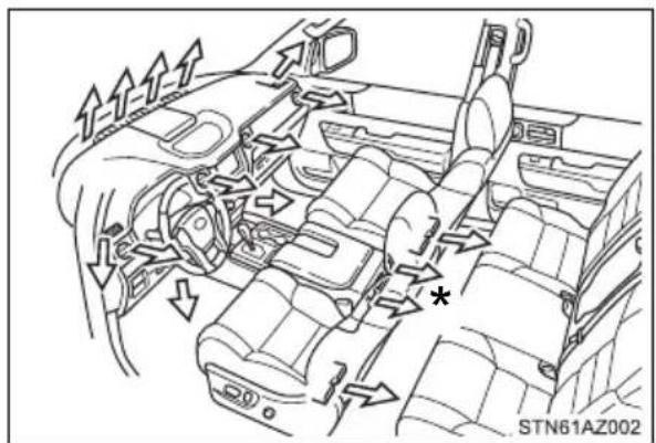
*: CrewMax models
■ Adjusting the position of and opening and closing the air outlets
Front
Direct air flow to the left or right, up or down.
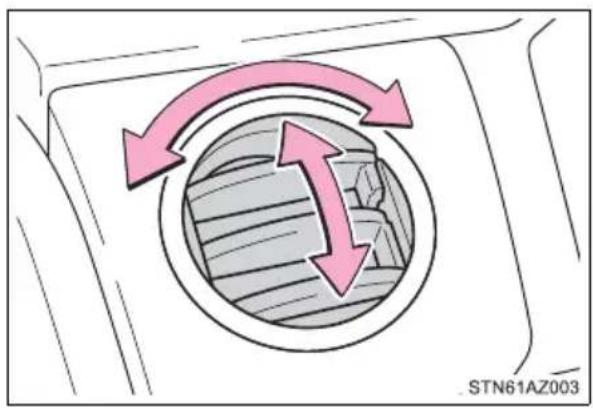
natural_image
Diagram showing two pink arrows pointing inward toward a circular patterned area, with no readable text or symbols.① Open the vent
② Close the vent
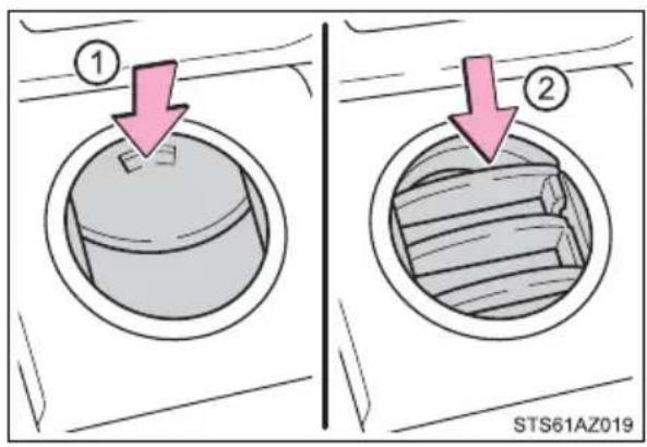
▶ Rear (CrewMax models)
① Direct air flow to the left or right, up or down.
② Turn the knob to open or close the vent.
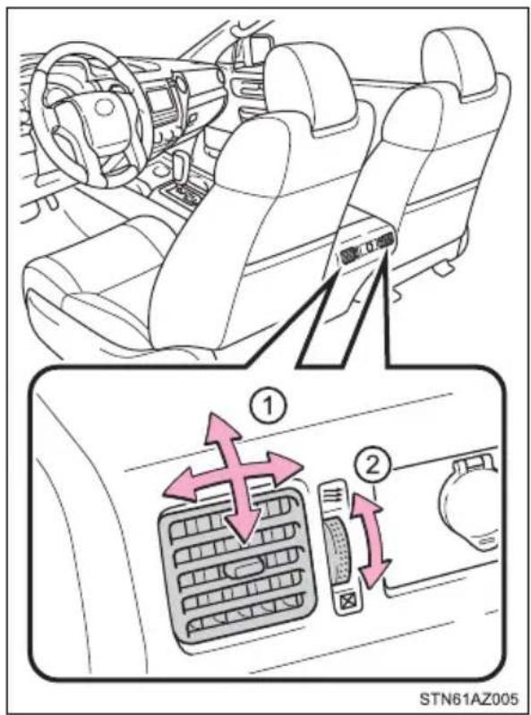
■ Using automatic mode
Fan speed is adjusted automatically according to the temperature setting and the ambient conditions.
Therefore, the fan may stop for a while until warm or cool air is ready to flow immediately after is pressed.
■Fogging up of the windows
- The windows will easily fog up when the humidity in the vehicle is high. Turning out will dehumidify the air from the outlets and defog the windshield effectively.
- If you turn off the windows may fog up more easily.
●The windows may fog up if the recirculated air mode is used.
■When driving on dusty roads
Close all windows. If dust thrown up by the vehicle is still drawn into the vehicle after closing the windows, it is recommended that the air intake mode be set to outside air mode and the fan speed to any setting except off.
■ Outside/recirculated air mode
- Setting to the recirculated air mode temporarily is recommended in preventing dirty air from entering the vehicle interior and helping to cool the vehicle when the outside air temperature is high.
● Outside/recirculated air mode may automatically switch depending on the temperature setting or the inside temperature.
■ When the outside temperature exceeds 75^ F ( 24^ C) and the air conditioning system is on
- In order to reduce the air conditioning power consumption, the air conditioning system may switch to recirculated air mode automatically. This may also reduce fuel consumption.
● Recirculated air mode is selected as a default mode when the engine switch is in ON. - It is possible to switch to outside air mode at any time by pressing
■ When the outside temperature falls to nearly 32^ F ( 0^ C)
The dehumidification function may not operate even when is selected.
■Ventilation and air conditioning odors
● To let fresh air in, set the air conditioning system to the outside air mode.
● During use, various odors from inside and outside the vehicle may enter into and accumulate in the air conditioning system. This may then cause odor to be emitted from the vents.
●To reduce potential odors from occurring:
- It is recommended that the air conditioning system be set to outside air mode prior to turning the vehicle off.
- The start timing of the blower may be delayed for a short period of time immediately after the air conditioning system is started in automatic mode.
Air conditioning filter
→P. 448

WARNING
■To prevent the windshield from fogging up
- Do not use during cool air operation in extremely humid weather. The difference between the temperature of the outside air and that of the windshield can cause the outer surface of the windshield to fog up, blocking your vision.
- Do not place anything on the instrument panel which may cover the air outlets. Otherwise, air flow may be obstructed, preventing the windshield defoggers to defog.
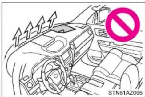
■ To prevent burns (vehicles with rear view mirror defoggers and wind-shield wiper de-icer)
- Do not touch the rear view mirror surfaces when the outside rear view mirror defoggers are on.
- Do not touch the glass at lower part of the windshield or to the side of the front pillars, when the windshield wiper de-icer is on.

NOTICE
■To prevent battery discharge
Do not leave the air conditioning system on longer than necessary when the engine is stopped.
Seat heaters\*/seat ventilators\*
The seat heaters and ventilators heat the seats and maintain good airflow by blowing air from the seats.
Seat heaters
Turns the seat heater on
① Hi
② Mid
③ Lo
④ Off
The level indicator lights come on.
Press the “^” on the button to up and “v” to down, and off.
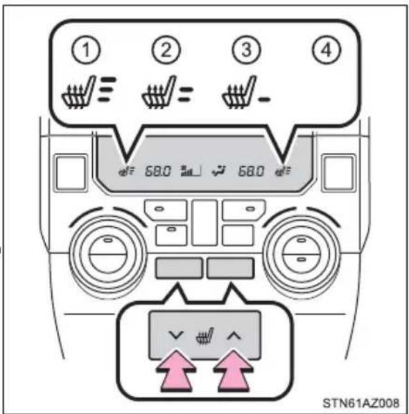
Seat ventilators
- Seat heater
Turns the seat heater on
① Hi
② Mid
③ Lo
④ Off
The level indicator lights come on.
Pressing the button changes modes in the following:
Hi→Mid→Lo→Off
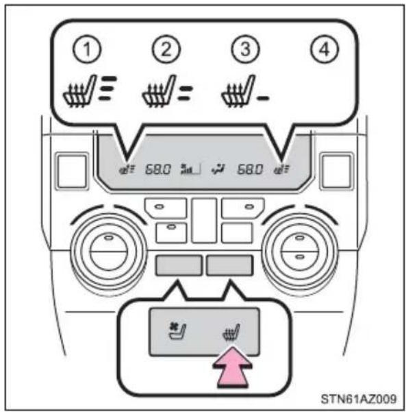
■Seat ventilators
Blows air from the seat
① Hi
② Mid
③ Lo
④ Off
The level indicator lights come on. Pressing the button changes modes in the following: Hi→Mid→Lo→Off
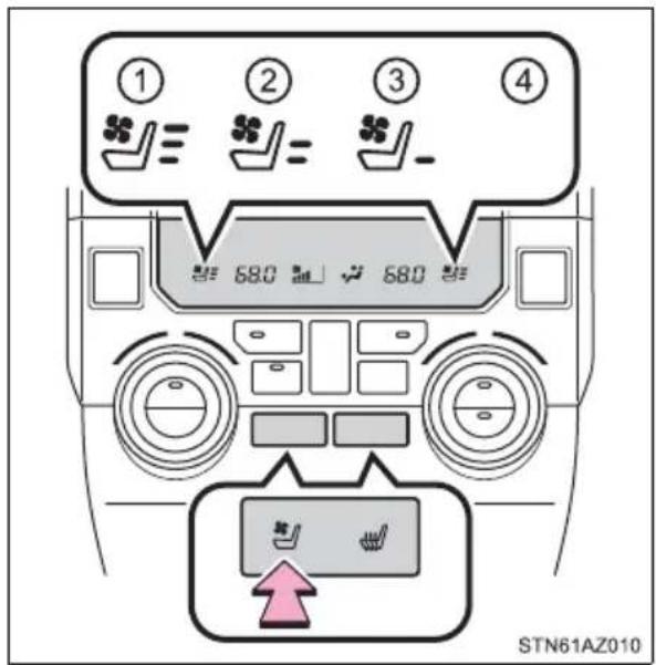
■The seat heaters/seat ventilators can be used when
The engine switch is in ON.
■ Passenger seat ventilator timer (vehicles with seat ventilators)
● The ventilator operates on for 5 minutes after the button is pressed.
- When the passenger is not detected, the automatically turns off the ventilator after 5 minutes.
When not in use
Turn the seat heaters or seat ventilators off by pressing the button. The indicator light turns off.

WARNING
Burns
- Use caution when seating the following persons in a seat with the seat heater on to avoid the possibility of burns:
- Babies, small children, the elderly, the sick and the physically challenged
• Persons with sensitive skin
• Persons who are fatigued - Persons who have taken alcohol or drugs that induce sleep (sleeping drugs, cold remedies, etc.)
- Do not cover the seat with anything when using the seat heater. Using the seat heater with a blanket or cushion increases the temperature of the seat and may lead to overheating.
- Do not use seat heater more than necessary. Doing so may cause minor burns or overheating.

NOTICE
■To prevent damage to the seat heaters/seat ventilators
Do not put heavy objects that have an uneven surface on the seat and do not stick sharp objects (needles, nails, etc.) into the seat.
■To prevent battery discharge
Turn the seat heaters/seat ventilators off when the engine is not running.
Interior lights list
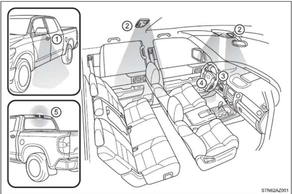
① Outer foot lights (if equipped)
② Personal/interior lights
(→P. 358)
③ Engine switch light (if equipped)
④ Foot well lighting (if equipped)
⑤ Cargo lamp ( P. 359)
Personal/interior lights main switch
① “OFF”
The personal/interior lights can be individually turned on or off.
② “DOOR”
The personal/interior lights come on when a door is opened. They turn off when the doors are closed.
③ “ON”
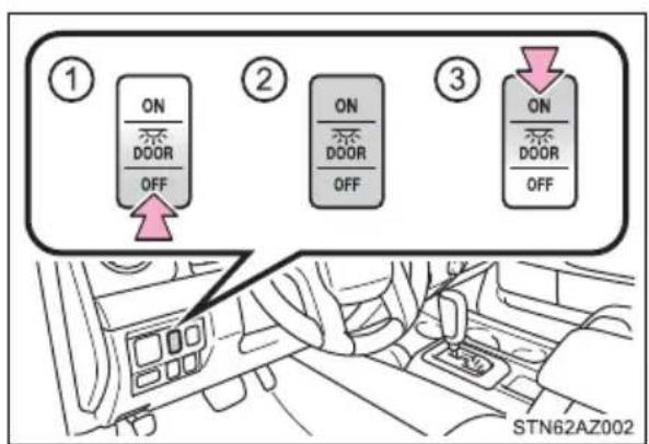
The personal/interior lights cannot be individually turned off.
Personal/interior lights
Front
On/off
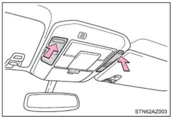
natural_image
Interior view of a car dashboard with directional arrows indicating movement or flow (no text or symbols)Rear
▶ Type A On/off
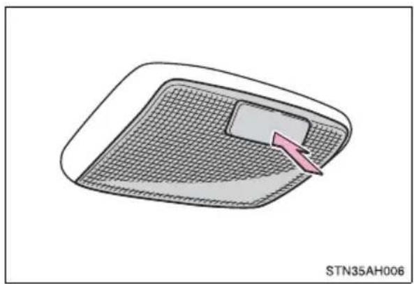
natural_image
Diagram of a device with mesh pattern and a pink arrow pointing to a component, labeled 'STN35AH006' (no other text or symbols)▶ Type B On/off
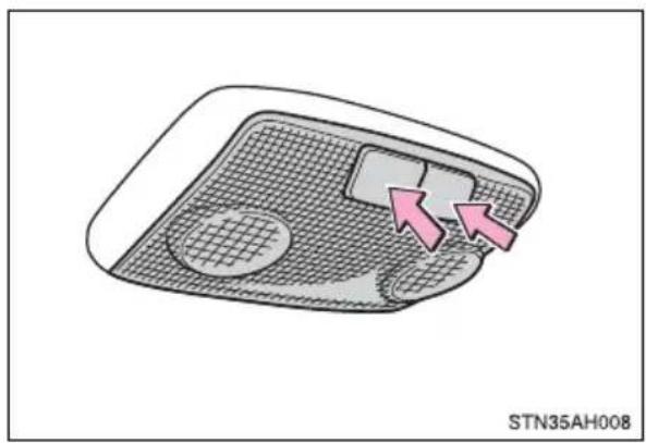
natural_image
Diagram of a device interior with a mesh grille and two pink arrows pointing to a component (no text or symbols)Cargo lamp main switch
① “OFF”
The cargo lamp can be individually turned on or off.
② “DOOR”
The cargo lamp comes on when a door is opened. They turn off when the doors are closed.
③ “ON”
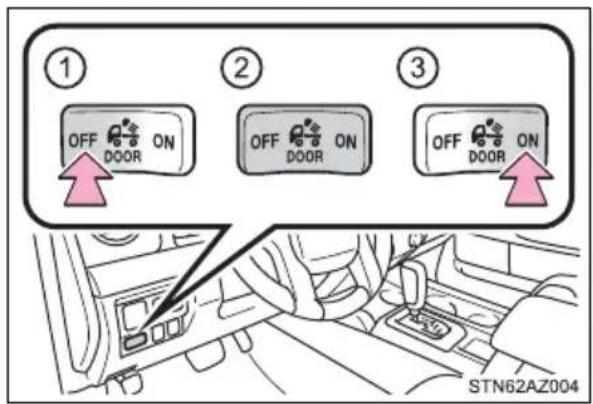
The cargo lamp cannot be individually turned off.
■Illuminated entry system
▶ Vehicles without a smart key system
The lights automatically turn on/off according to the engine switch position, whether the doors are locked/unlocked, and whether the doors are opened/closed.
▶ Vehicles with a smart key system
The lights automatically turn on/off according to engine switch mode, the presence of the electronic key, whether the doors are locked/unlocked, and whether the doors are opened/closed.
■To prevent battery discharge
If the following lights remain on when the door is not fully closed and the main switch is in the "DOOR" position, the lights will go off automatically after 20 minutes:
●Personal lights
- Interior lights
- Cargo lamp
■Customization that can be configured at Toyota dealer
Settings (e.g. the time elapsed before lights turn off) can be changed. (Customizable features: →P. 564)
List of storage features
▶ Front separated type seats
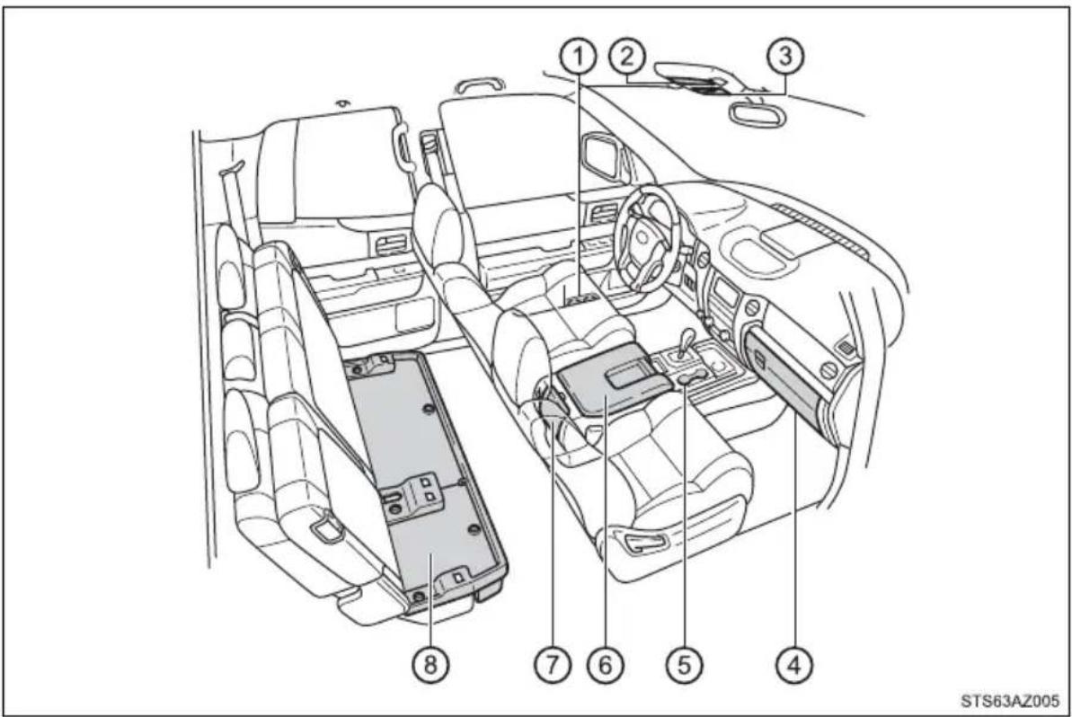
① Bottle holders ( P. 372)
② Card holder ( P. 364)
③ Overhead console ( P. 369)
④ Glove box ( P. 362)
⑤ Front cup holders ( P. 370)
⑥ Console box ( P. 363)
- Card holder (→P. 364)
- Pen holder ( P. 367)
• Tissue pocket (→P. 368)
⑦ Rear cup holders (if equipped)
(→P. 371)
⑧ Storage box (if equipped)
(→P. 375)
Front bench type seat
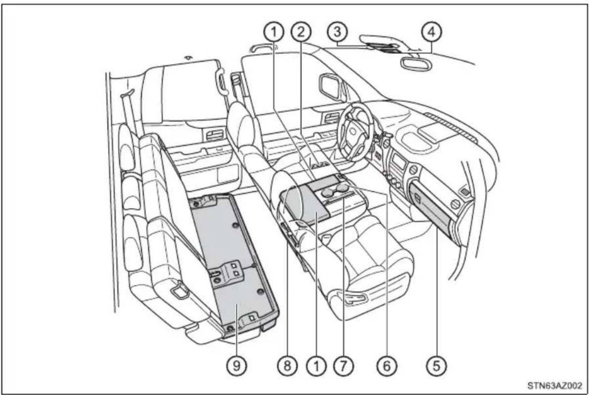
① Auxiliary boxes ( P. 373)
- Card holder ( P. 364)
- Map holder (→P. 366)
• Tissue pocket (→P. 368)
② Bottle holders ( P. 372)
③ Card holder ( P. 364)
④ Overhead console ( P. 369)
⑤ Glove box ( P. 362)
⑥ Front cup holders ( P. 370)
⑦ Pen holder ( P. 367)
⑧ Rear cup holders (if equipped)
$$ (\rightarrow \mathrm{P}. 3 7 1) $$
⑨ Storage box (if equipped)
$$ (\rightarrow \mathrm{P}. 3 7 5) $$

WARNING
■Items that should not be left in the storage spaces
Do not leave glasses, lighters or spray cans in the storage spaces, as this may result in the following when cabin temperature becomes high:
●Glasses may be deformed by heat or cracked if they come into contact with other stored items.
●Lighters or spray cans may explode. If they come into contact with other stored items, the lighter may catch fire or the spray can may release gas, causing a fire hazard.
■When driving or when the storage compartments are not in use
Keep the lids closed.
In the event of sudden braking or sudden swerving, an accident may occur due to an occupant being struck by an open lid or the items stored inside.
Glove box
① Open (pull the lever up)
② Lock
③ Unlock
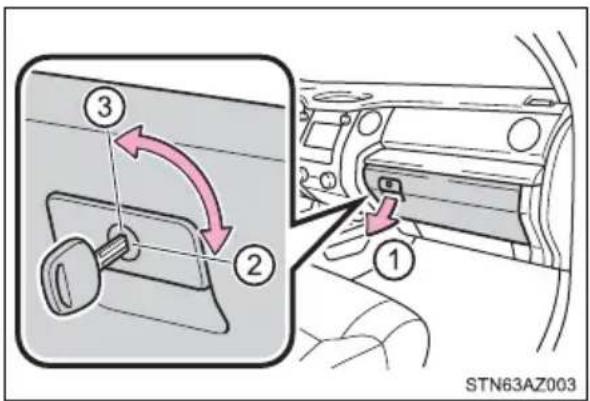
Console box (front separated type seat)
Pull the knob up and lift the lid
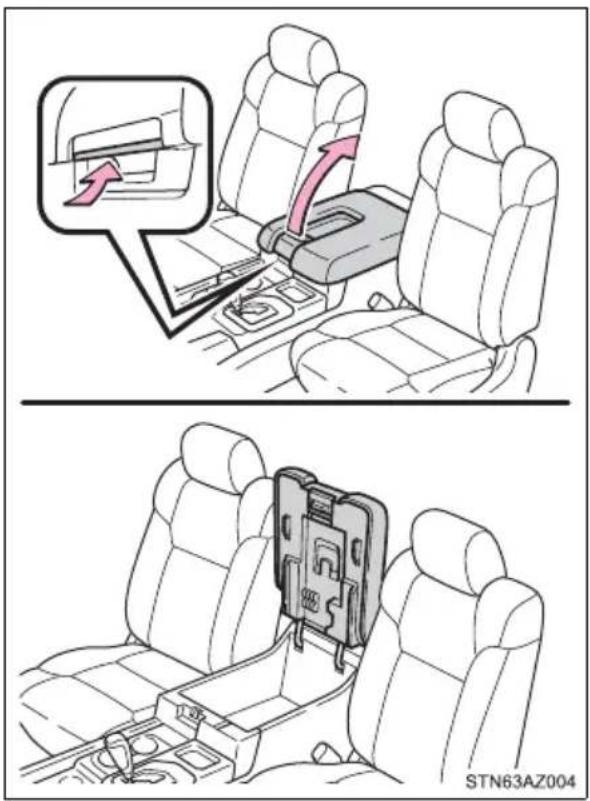
■Passing a cable from the console box
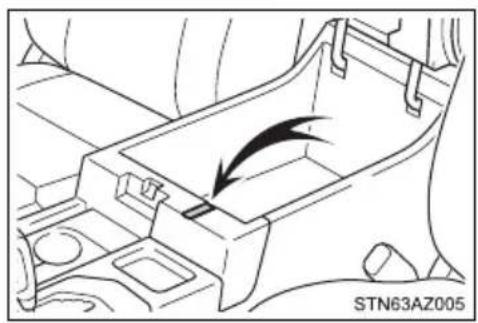
natural_image
Technical line drawing of a mechanical component with an arrow indicating direction (no text or symbols)Card holder
■Overhead console
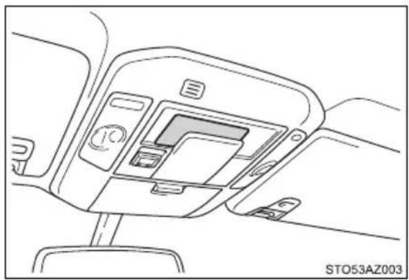
natural_image
Line drawing of a car interior panel with no visible text or symbols■ Console box (front separated type seats)
Pull the knob up and lift the lid
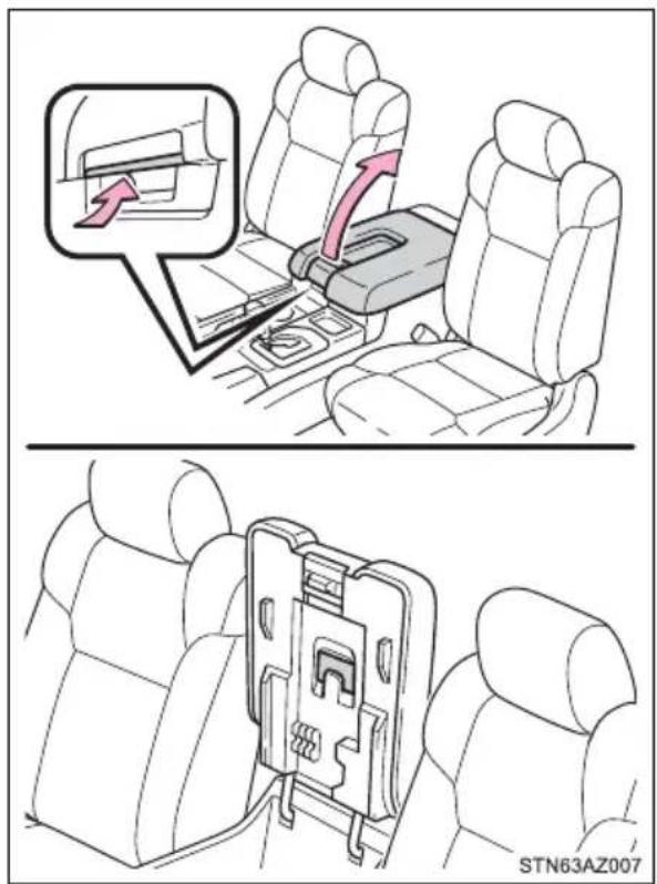
■Back of the front center seatback (front bench type seat)
1 Pull the lever up and fold down the seatback
2 Push the knob and lift the lid
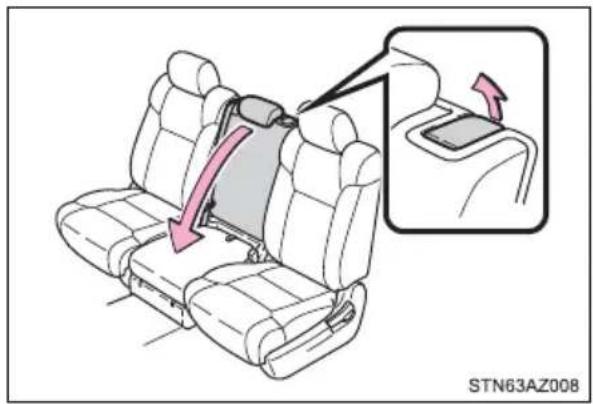
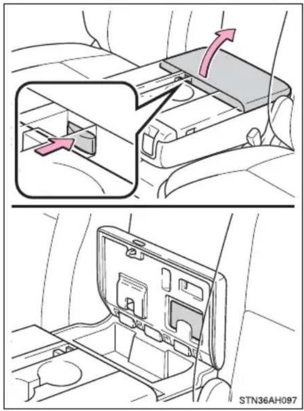
Map holder (front bench type seat)
1 Pull the lever up and fold down the seatback
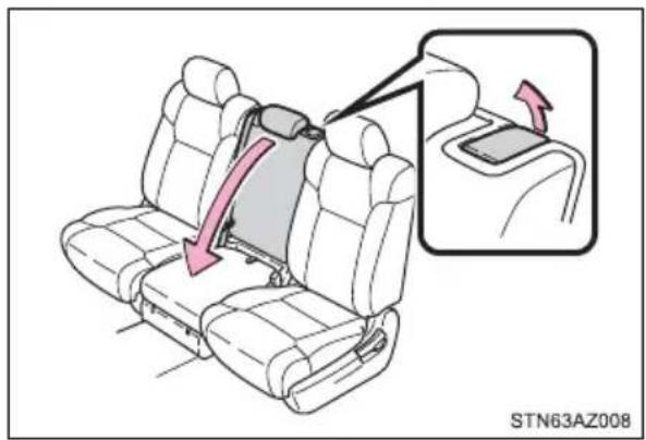
2 Push the knob and lift the lid
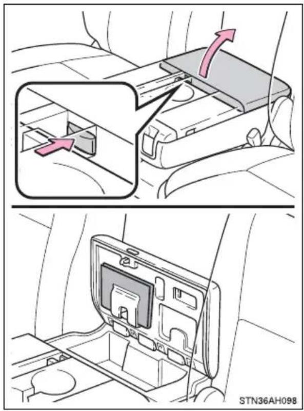
Pen holder
▶ Front separated type seats Pull the knob up and lift the lid
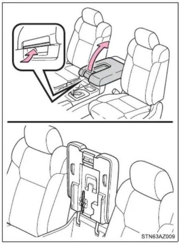
Front bench type seat Pull the lever up and fold down the seatback
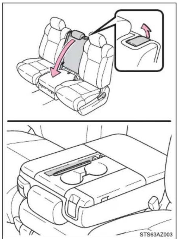
Tissue pocket
Front separated type seats Pull the knob up and lift the lid
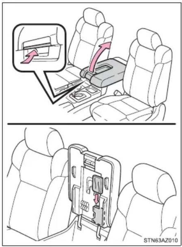
Front bench type seat
1 Pull the lever up and fold down the seatback
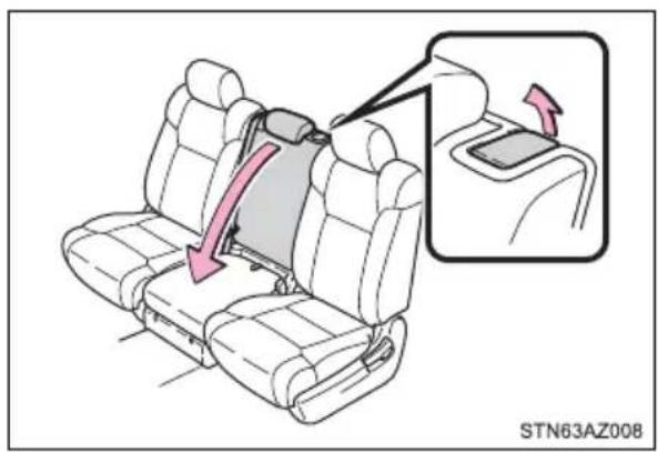
natural_image
Diagram of a car seat assembly with a highlighted side panel showing a red arrow indicating movement (no text or symbols present)2 Push the knob and lift the lid
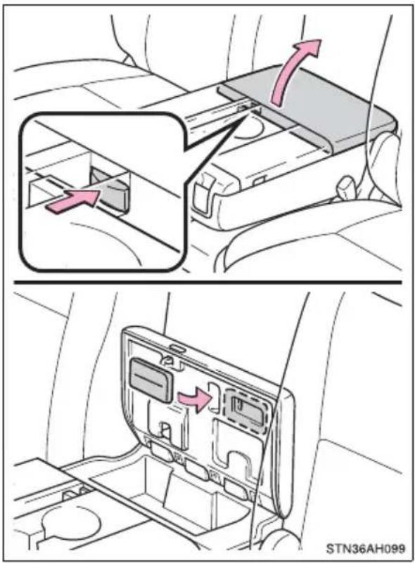
Overhead console
The overhead console is useful for temporarily storing sunglasses and similar small items.
Push the knob forward to open the console
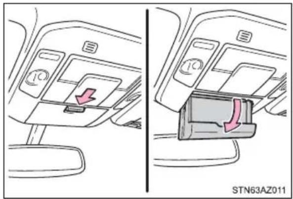
Cup holders
Front
▶ Separated type seats
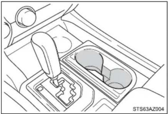
natural_image
Line drawing of a car gear shift lever inside a vehicle (no text or symbols)▶ Bench type seat
Pull the lever up and fold down the seatback
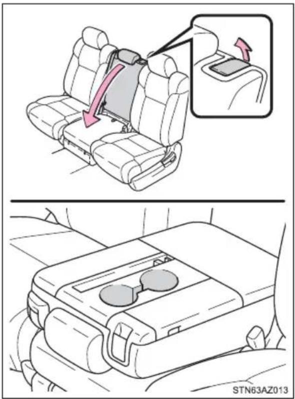
Rear
▶ Double Cab models with front separated type seats
Pull the lid down
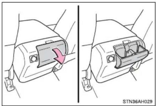
natural_image
Diagram showing two views of a car intake manifold with a pink arrow indicating direction (no text or symbols)▶ Double Cab models with front bench type seat
Pull the lid down
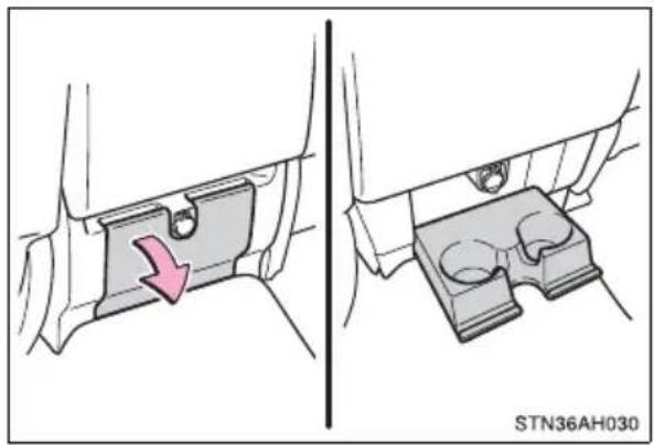
natural_image
Mechanical component diagram showing a bracket with a red arrow indicating direction, no text or symbols present▶ CrewMax models
Pull the armrest down
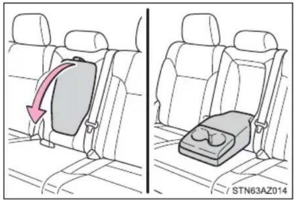
natural_image
Side-by-side illustration of a car backseat and seatbelt, showing seatbelt placement with a red arrow indicating direction (no text or symbols)
WARNING
■Items unsuitable for the cup holder
Do not place anything other than cups or beverage cans in the cup holders. Other items may be thrown out of the holders in the event of an accident or sudden braking and cause injury. If possible, cover hot drinks to prevent burns.
Bottle holders
Front door
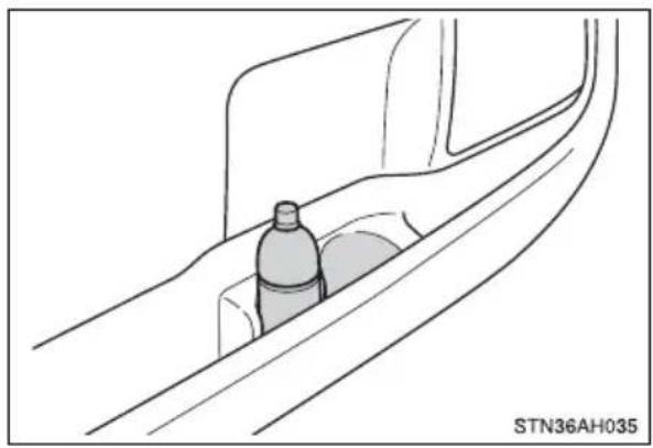
natural_image
Technical line drawing of a mechanical component or bracket with no visible text or symbols▶ Rear door (CrewMax models)
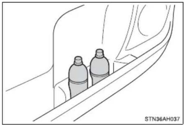
natural_image
Line drawing of two bottles on a vehicle side panel, no text or symbols presentWARNING
Items unsuitable for the bottle holders
Do not place anything other than a bottle in the bottle holders. Other items may be thrown out of the holders in the event of an accident or sudden braking and cause injury.
NOTICE
Items that should not be stowed in the bottle holders
Put the cap on before stowing a bottle. Do not place open bottles in the bottle holders, or glasses and paper cups containing liquid. The contents may spill and glasses may break.
Auxiliary boxes (front bench type seat)
▶ Type A
Pull the strap
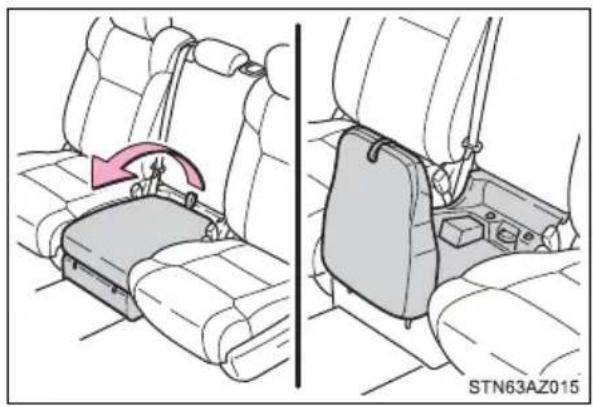
natural_image
Diagram showing car seatbelt insertion and rear compartment assembly (no text or symbols)▶ Type B
1 Pull the lever up and fold down the seatback
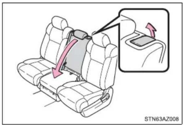
2 Push the knob and lift the lid
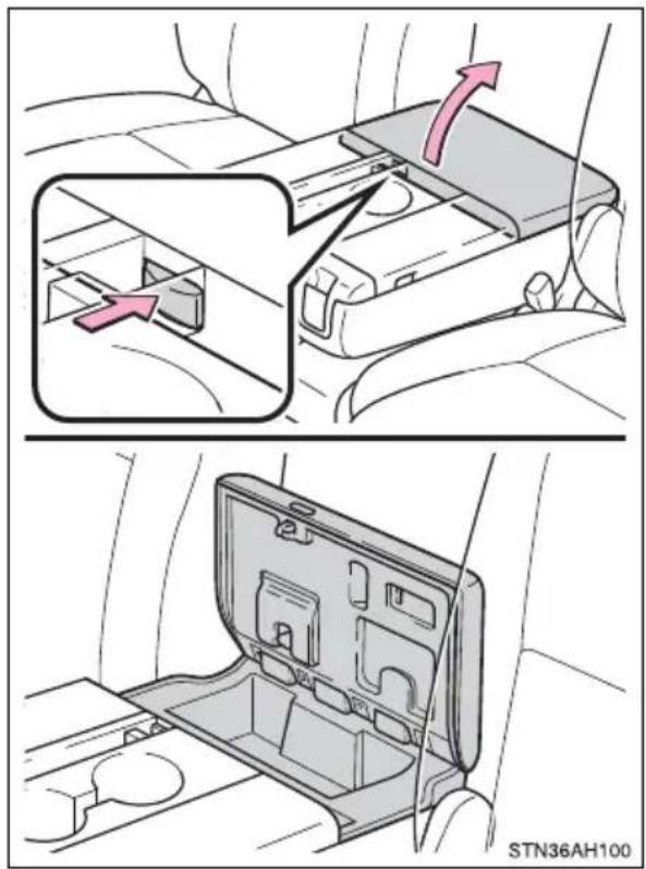
▶ Type C
1 Pull the lever up and fold down the seatback
2 Push the knob and lift the lid
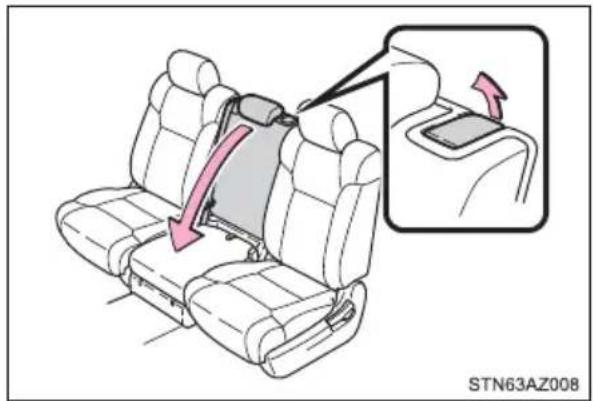
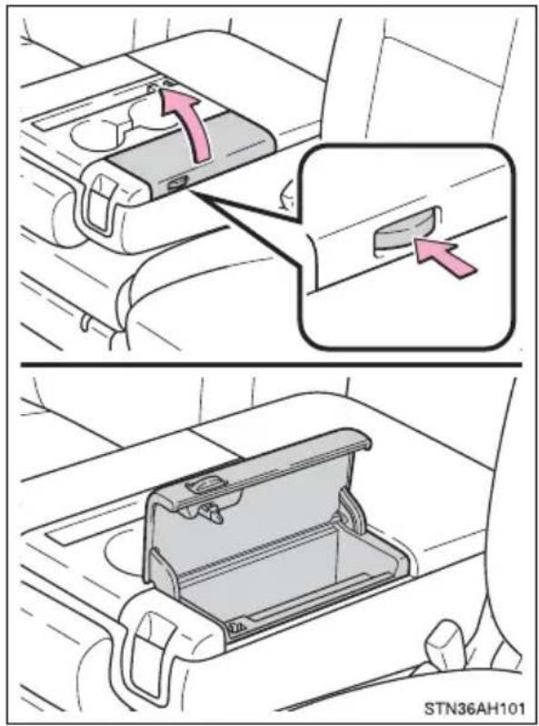
Storage box (if equipped)
■ Using the storage box
1 Pull the lever up and raise the rear seat cushion
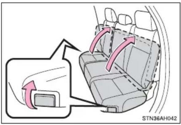
2 Open the lid
① Turn the knob in the "OPEN" direction
② Lift the lid
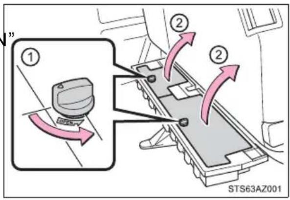
■Remove the storage box
1 Pull the lever up and raise the rear seat cushion
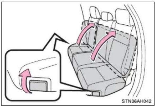
2 Open the lid
① Turn the knob in the "OPEN direction
② Lift the lid
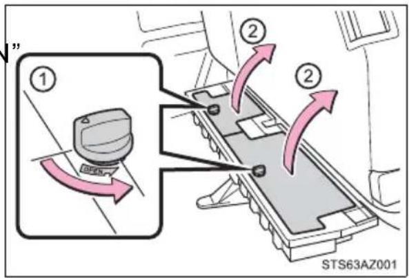
3 Remove the storage box
① Remove the lids
② Turn the knobs counterclockwise
③ Remove the storage box
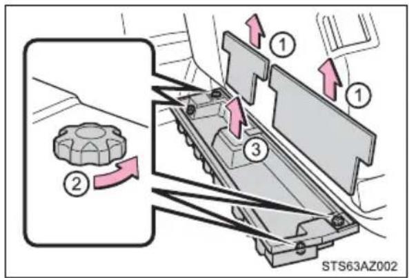

WARNING
■To prevent damage to the storage box
Do not put heavy loads on the lids.
Luggage compartment features
Deck hooks
Deck hooks are securing loose items.
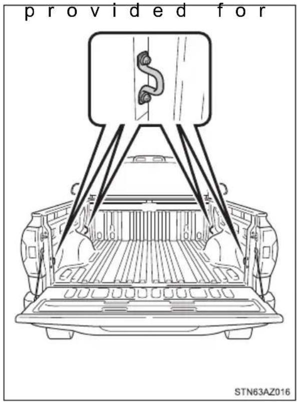
Other interior features
Sun visors
① To set the visor in the forward position, flip it down.
② To set the visor in the side position, flip down, unhook, and swing it to the side.
③ To use the side extender, place the visor in the side position, then slide it backward.
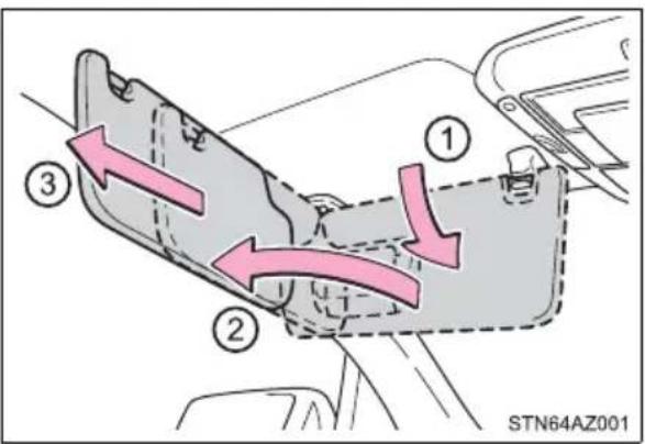
Vanity mirrors (if equipped)
Open the cover
The light turns on when the cover is opened.
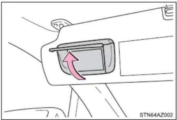
natural_image
Diagram of a car seatbelt switch with a red arrow indicating clockwise motion (no text or symbols)
NOTICE
Do not leave the vanity lights on for extended periods while the engine is stopped.
Power outlets
Please use as a power supply for electronic goods that use less than 12 VDC/10 A (power consumption of 120 W).
When using electronic goods, make sure that the power consumption of all the connected power outlets is less than 120 W.
▶ Type A (instrument panel)
Open the lid.
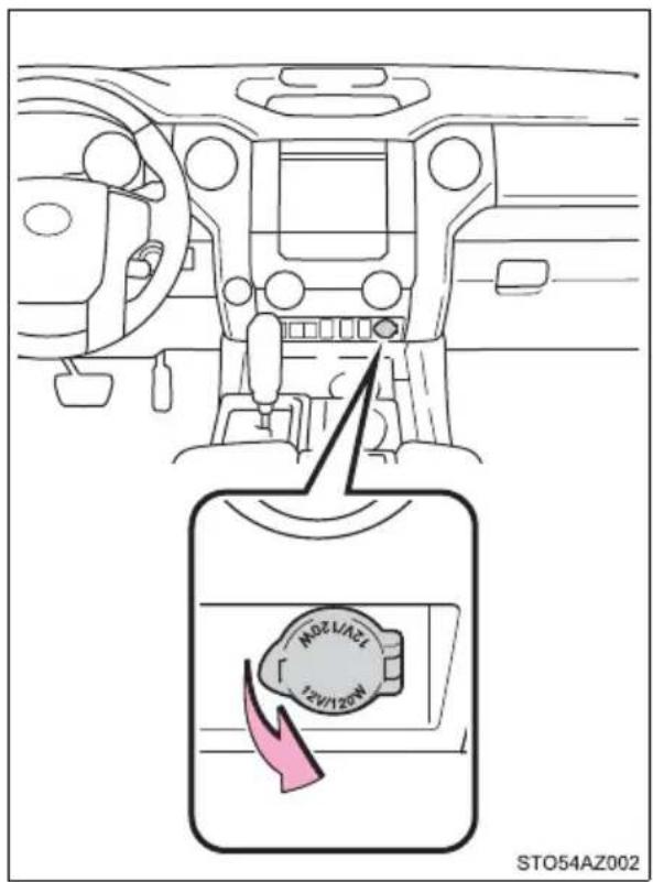
▶ Type B (back of the front center seatback)
Open the lid.
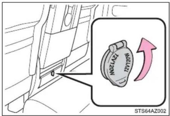
▶ Type C (back of the front center seatback)
Open the lid.
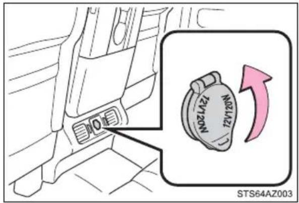
▶ Type D (inside of the console box)
Pull the knob up and lift the lid, and open the lid.
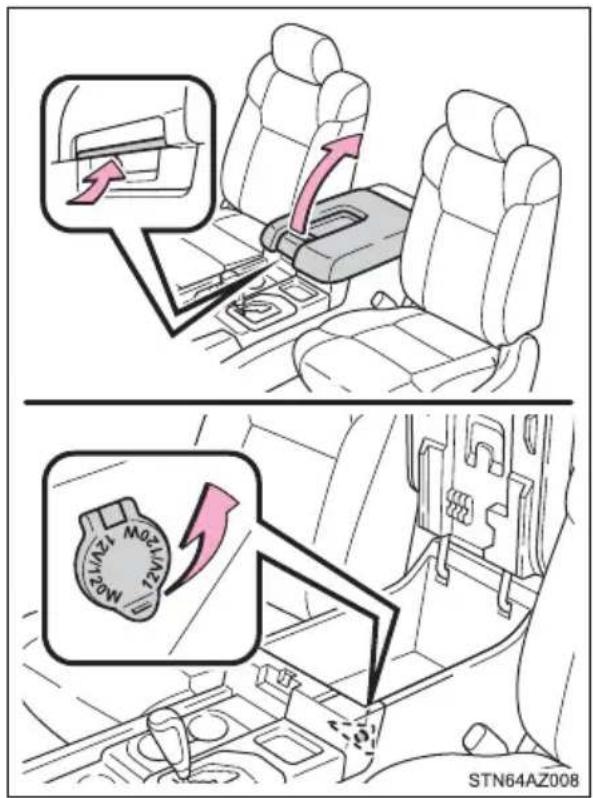
▶ Type E (back of the console box)
Open the lid.
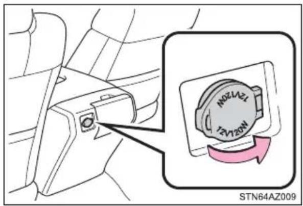
▶ Type F (back of the console box)
Open the lid.
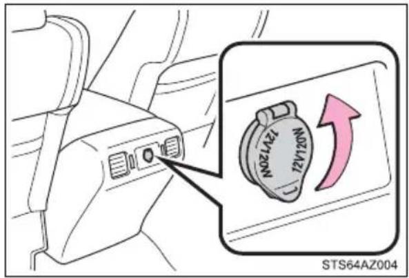
■The power outlets can be used when
The engine switch is in ACC or ON.
■Passing a cable from the console box (type D)
→P. 363
■When turning the engine switch off
Disconnect electrical devices with charging functions, such as mobile battery packs.
If such devices are left connected, the engine switch may not be turned off normally.

NOTICE
- Close the power outlet lids when the power outlets are not in use.
Foreign objects or liquids that enter the power outlets may cause a short circuit. - Do not use the power outlets longer than necessary when the engine is not running.
USB charging ports
The USB charging ports are used to supply 2.1 A of electricity at 5 V to external devices.
The USB charging ports are for charging only. They are not designed for data transfer or other purposes.
Depending on the external device, it may not charge properly. Refer to the manual included with the device before using a USB charging port.
■Using the USB charging ports
Open the lid.
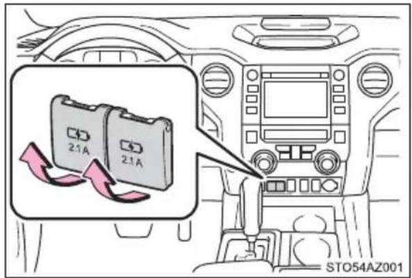
■The USB charging ports can be used when
The engine switch is in ACC or ON.
■ Situations in which the USB charging ports may not operate correctly
- If a device which consumes more than 2.1 A at 5 V is connected
- If a device designed to communicate with a personal computer, such as a USB memory device, is connected
● If the connected external device is turned off (depending on device) - If the temperature inside the vehicle is high, such as after the vehicle has been parked in the sun
■About connected external devices
Depending on the connected external device, charging may occasionally be suspended and then start again. This is not a malfunction.

NOTICE
■To prevent damage to the USB charging ports
- Do not insert foreign objects into the ports.
- Do not spill water or other liquids into the ports.
- When the USB charging ports are not in use, close the lids. If a foreign object or liquid enters a port may cause a short circuit.
- Do not apply excessive force to or impact the USB charging ports.
- Do not disassemble or modify the USB charging ports.
■To prevent damage to external devices
- Do not leave external devices in the vehicle. The temperature inside the vehicle may become high, resulting in damage to an external device.
- Do not push down on or apply unnecessary force to an external device or the cable of an external device while it is connected.
■To prevent battery discharge
Do not use the USB charging ports for a long period of time with the engine stopped.
Armrest (CrewMax models)
Fold down the armrest for use.
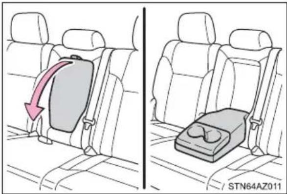

NOTICE
Do not apply too much load on the armrest.
Assist grips
An assist grip (type A) installed on the ceiling can be used to support your body while sitting on the seat.
An assist grip (type B) installed on the pillar can be used when getting in or out of the vehicle and others.
① Assist grip (type A)
② Assist grip (type B)
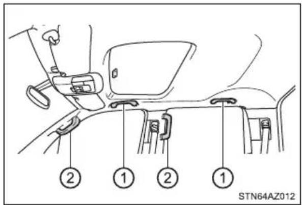

WARNING
■Assist grip (type A)
Do not use the assist grip when getting in or out of the vehicle or rising from your seat.
Doing so could damage the assist grip, or could cause you to injure yourself by falling over.

NOTICE
Do not hang any heavy object or put a heavy load on the assist grip.
The garage door opener can be programmed to operate garage doors, gates, entry doors, door locks, home lighting systems, security systems, and other devices.
HomeLink®
The HomeLink ^® wireless control system in your vehicle has 3 buttons which can be programmed to operate 3 different devices. Refer to the programming methods on the following pages to determine the method which is appropriate for the device.
① HomeLink ^® indicator light
② Garage door operation indicators
③ Buttons
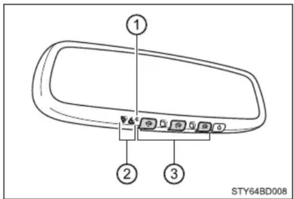
■Before programming the HomeLink®
●During programming, it is possible that garage doors, gates, or other devices may operate. For this reason, make sure that people and objects are clear of the garage door or other devices to prevent injury or other potential harm.
●It is recommended that a new battery be placed in the remote control transmitter for more accurate programming.
●Garage door opener motors manufactured after 1995 may be equipped with rolling code protection. If this is the case, you may need a stepladder or other sturdy, safe device to reach the “learn” or “smart” button on the garage door opener motor.
■Programming the HomeLink®
Steps through must be performed within 60 seconds, otherwise the indicator light will stop flashing and programming will not be able to be completed.
1 Press and release the HomeLink® button you want to program and check that the HomeLink® indicator light flashes orange.
2 Point the remote control transmitter for the device at the rear view mirror, 1 to 3 in. (25 to 75 mm) from the HomeLink® buttons.
Keep the HomeLink® indicator light in view while programming.
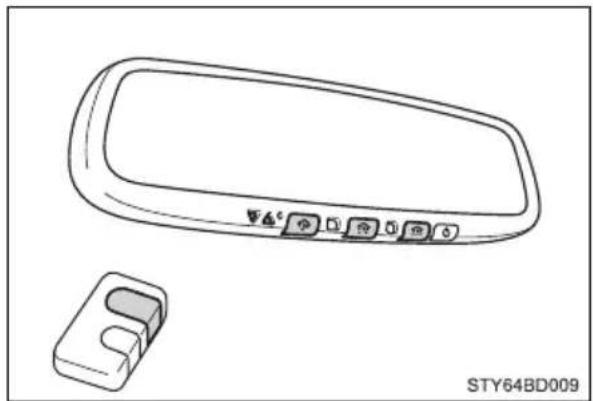
natural_image
Technical line drawing of a car rearview mirror and a small mechanical component (no text or symbols)3 Program a device.
▶ Programming a device other than an entry gate (for U.S.A. owners)
Press and hold the remote control transmitter button until the HomeLink® indicator light changes from slowly flashing orange to rapidly flashing green (rolling code) or continuously lit green (fixed code), then release the button.
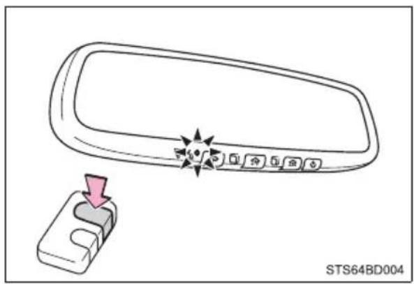
▶ Programming an entry gate (for U.S.A. owners)/Programming a device in the Canadian market
Press and release the remote control transmitter button at 2 second intervals, repeatedly, until the HomeLink® indicator light changes from slowly flashing orange to rapidly flashing green (rolling code) or continuously lit green (fixed code).
4 Test the HomeLink® operation by pressing the newly programmed button and observing the indicator light:
- Indicator light illuminates: Programming of a fixed code device has completed. The garage door or other device should operate when a HomeLink® button is pressed and released.
- Indicator light flashes rapidly: The garage door opener motor or other device is equipped with a rolling code. To complete programming, firmly press and hold the HomeLink ^® button for 2 seconds then release it.
- If the garage door or other device does not operate, proceed to "Programming a rolling code system".
5 Repeat the steps above to program another device for any of the remaining HomeLink® buttons.
■Programming a rolling code system
2 or more people may be necessary to complete rolling code programming.
1 Locate the "Learn" or "Smart" button on the garage door opener motor in the garage.
This button can usually be found where the hanging antenna wire is attached to the unit. The name and color of the button may vary by manufacturer. Refer to the Owner's manual supplied with the garage door opener motor for details.
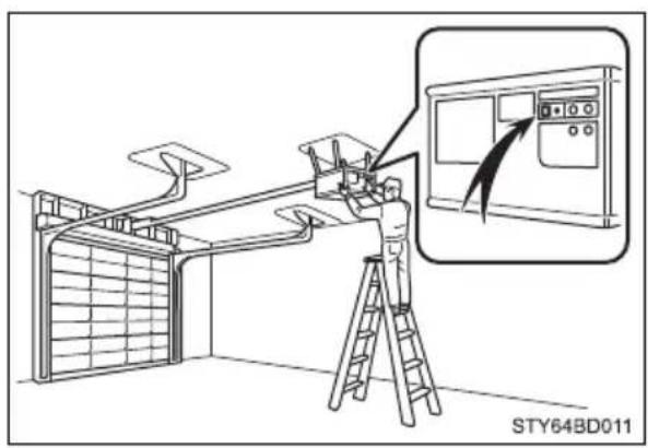
2 Press and release the "Learn" or "Smart" button. Perform Within 30 seconds after performing 2.
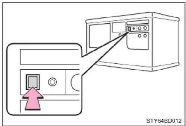
3 Press and hold the desired HomeLink® button (inside the vehicle) for 2 seconds and release it. Repeat this sequence (press/hold/release) up to complete programming. If the garage door opener motor operates when the HomeLink® button is pressed, the garage door opener motor recognizes the HomeLink® signal.
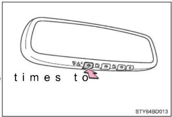
■Enabling 2-way communication with a garage door (only available for compatible devices)
When enabled, 2-way communication allows you to check the status of the opening and closing of a garage door through indicators in your vehicle.
2-way communication is only available if the garage door opener motor used is a compatible device. (To check device compatibility, refer to www.HomeLink.com.)
1 Within 5 seconds after programming the garage door opener has been completed, if the garage door opener motor is trained to HomeLink ^® , both garage door operation indicators will flash rapidly green and the light on the garage door opener motor will blink twice, indicating that 2-way communication is enabled.
If the indicators do not flash, perform 2 and 3 within the first 10 presses of the HomeLink® button after programming has been completed.
2 Press a programmed HomeLink® button to operate a garage door.
3 Within 1 minute of pressing the HomeLink® button, after the garage door operation has stopped, press the “Learn” or “Smart” button on the garage door opener motor. Within 5 seconds of the establishment of 2-way communication with the garage door opener, both garage door operation indicators in the vehicle will flash rapidly green and the light on the garage door opener motor will blink twice, indicating that 2-way communication is enabled.
■Reprogramming a single HomeLink ^® button
When the following procedure is performed, buttons which already have devices registered to them can be overwritten:
1 With one hand, press and hold the desired HomeLink® button.
2 When the HomeLink ^® indicator starts flashing orange, release the HomeLink ^® button and perform “Programming the HomeLink ^® ” (it takes 20 seconds for the HomeLink ^® indicator to start flashing).
Operating the HomeLink®
Press the appropriate HomeLink® button. The HomeLink® indicator light should turn on.
Garage door operation indicators
The status of the opening and closing of a garage door is shown by the indicators.
① Opening
② Closing
This function is only available if the garage door opener motor used is a compatible device. (To check device compatibility, refer to www.HomeLink.com.)
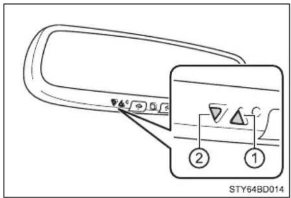
| Color Status | |
| Orange (flashing) Currently | opening/closing |
| Green | Opening/closing has completed |
| Red (flashing) | Feedback signals cannot be received |
The indicators can operate within approximately 820 ft. (250 m) of the garage door. However, if there are obstructions between the garage door and the vehicle, such as houses and trees, feedback signals from the garage door may not be received.
To recall the previous door operation status, press and release
either HomeLink® buttons and or and
simultaneously. The last recorded status will be displayed for 3 seconds.
Erasing the entire HomeLink ^® memory (all three codes)
Press and hold the 2 outside buttons for 10 seconds until the HomeLink® indicator light changes from continuously lit orange to rapidly flashing green.
If you sell your vehicle, be sure to erase the programs stored in the HomeLink® memory.
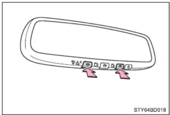
natural_image
Diagram of a car rearview mirror with two directional arrows pointing to the lens (no text or symbols)■Codes stored in the HomeLink® memory
● The registered codes are not erased even if the battery cable is disconnected.
- If learning failed when registering a different code to a HomeLink ^ button that already has a code registered to it, the already registered code will not be erased.
■Before programming
● Install a new battery in the transmitter.
●The battery side of the transmitter must be pointed away from the Home-Link®.
■Certification for the garage door opener
For vehicles sold in the U.S.A.
FCC ID: NZLAECHL5
NOTE:
This device complies with part 15 of the FCC Rules. Operation is subject to the following two conditions: (1) this device may not cause harmful interference, and (2) This device must accept any interference received, including interference that may cause undesired operation.
FCC WARNING:
Changes or modifications not expressly approved by the party responsible for compliance could void the user's authority to operate the equipment.
For vehicles sold in Canada
NOTE:
This device complies with Industry Canada licence-exempt RSS standard(s). Operation is subject to the following two conditions: (1) this device may not cause interference, and (2) this device must accept any interference, including interference that may cause undesired operation of the device.
REMARQUE:
■When support is necessary
Visit on the web at www.homelink.com/toyota or call 1-800-355-3515.
About HomeLink®
HomeLink and the HomeLink house icon are registered trademarks of Gentex Corporation.

WARNING
■ When programming a garage door or other remote control device
The garage door or other device may operate, so ensure people and objects are out of danger to prevent potential harm.
■Conforming to federal safety standards
Do not use the HomeLin® compatible transceiver with any garage door opener or device that lacks safety stop and reverse features as required by federal safety standards.
This includes any garage door that cannot detect an interfering object. A door or device without these features increases the risk of death or serious injury.
■When operating or programming HomeLink®
Never allow a child to operate or play with the HomeLink® buttons.
Compass\*
The compass on the inside rear view mirror indicates the direction in which the vehicle is heading.
Operation
To turn the compass on or off, press and hold the button for 3 seconds.
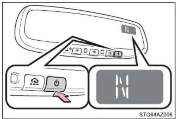
Displays and directions
| Display Direction | |
| N North | |
| NE Northeast | |
| E East | |
| SE Southeast | |
| S South | |
| SW Southwest | |
| W West | |
| NW Northwest |
Calibrating the compass
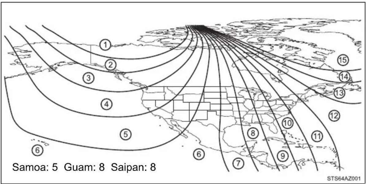
The direction display deviates from the true direction determined by the earth's magnetic field. The amount of deviation varies according to the geographic position of the vehicle.
If you cross over a map boundary shown in illustration, the compass will deviate.
To obtain higher precision of accurate calibration, refer to the following.
■ Deviation calibration
1 Stop the vehicle.
2 Press and hold the button for 6 seconds.
A number (1 to 15) appears on the compass display.
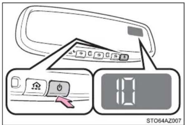
3 Press the switch, and referring to the map above, select the number of the zone where you are.
If the direction is displayed several seconds after adjustment, the calibration is complete.
■ Circling calibration
1 Stop the vehicle in a place where it is safe to drive in a circle.
2 Press and hold the button for 9 seconds.
"C" appears on the compass display.
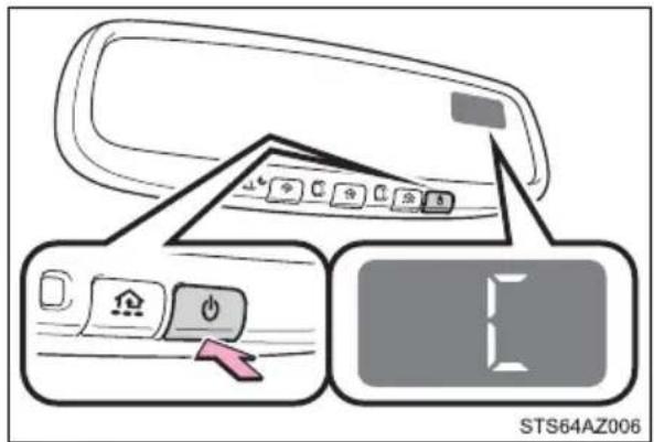
3 Drive the vehicle at 5 mph (8 km/h) or less in a circle until a direction is displayed.
If there is not enough space to drive in a circle, drive around the block until the direction is displayed.
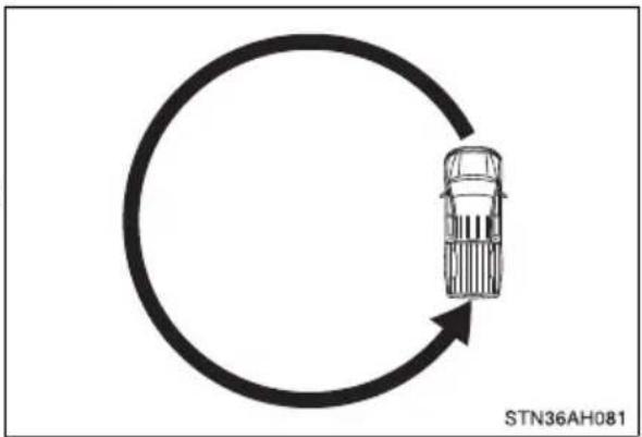
natural_image
Diagram showing a car moving in a circular cycle with an arrow indicating direction (no text or symbols on the diagram itself)■Conditions unfavorable to correct operation
The compass may not show the correct direction in the following conditions:
●The vehicle is stopped immediately after turning.
●The vehicle is on an inclined surface.
- The vehicle is in a place where the earth's magnetic field is subject to interference by artificial magnetic fields (underground car park/parking lot, under a steel tower, between buildings, roof car park/parking lot, near an intersection, near a large vehicle, etc.).
●The vehicle has become magnetized. (There is a magnet or metal object near the inside rear view mirror.)
●The battery has been disconnected.
●A door is open.

WARNING
■When driving the vehicle
Do not adjust the display. Be sure to adjust the display only when the vehicle is stopped.
■When doing the circling calibration
Be sure to secure a wide space, and watch out for people and vehicles in the neighborhood. Do not violate any local traffic rules while performing circling calibration.

NOTICE
■To avoid the compass malfunctions
Do not place magnets or any metal objects near the inside rear view mirror. Doing this may cause a malfunction of the compass sensor.
■To ensure normal operation of the compass
- Do not perform circling calibration of the compass in a place where the earth's magnetic field is subject to interference by artificial magnetic fields.
During calibration, do not operate electric systems (moon roof, power windows, etc.) as they may interfere with the calibration.
Maintenance and care
6
6-1. Maintenance and care
Cleaning and protecting
the vehicle exterior...... 400
Cleaning and protecting
the vehicle interior...... 403
6-2. Maintenance
Maintenance
requirements...... 406
General maintenance..... 408
Emission inspection
and maintenance (I/M)
programs...... 411
6-3. Do-it-yourself maintenance
Do-it-yourself service
precautions 412
Hood 414
Engine compartment...... 415
Tires 426
Tire inflation pressure ..... 442
Wheels 445
Air conditioning filter...... 448
Wireless remote control/
electronic key battery..... 451
Checking and replacing
fuses 454
Light bulbs.... 457
Cleaning and protecting the vehicle exterior
Perform the following to protect the vehicle and maintain prime condition:
●Working from top to bottom, liberally apply water to the vehicle body, wheel wells and underside of the vehicle to remove any dirt and dust.
●Wash the vehicle body using a sponge or soft cloth, such as a chamois.
●For hard-to-remove marks, use car wash soap and rinse thoroughly with water.
●Wipe away any water.
● Wax the vehicle when the waterproof coating deteriorates.
If water does not bead on a clean surface, apply wax when the vehicle body is cool.
■Automatic car washes
- Fold the mirrors and remove the antenna before washing the vehicle. Start washing from the front of the vehicle. Make sure to re-install the antenna and extend the mirrors before driving.
- Brushes used in automatic car washes may scratch the vehicle surface, parts (wheel, etc.) and harm your vehicle's paint.
■High pressure car washes
As water may enter the cabin, do not bring the nozzle tip near the gaps around the doors or perimeter of the windows, or spray these areas continuously.
Wheels and wheel ornaments (if equipped)
- Remove any dirt immediately by using a neutral detergent.
●Wash detergent off with water immediately after use.
● To protect the paint from damage, make sure to observe the following precautions. - Do not use acidic, alkaline or abrasive detergent
- Do not use hard brushes
- Do not use detergent on the wheels when they are hot, such as after driving or parking in hot weather
Bumpers
Do not scrub with abrasive cleaners.
Plated portions
If dirt cannot be removed, clean the parts as follows:
- Use a soft cloth dampened with an approximately 5% solution of neutral detergent and water to clean the dirt off.
● Wipe the surface with a dry, soft cloth to remove any remaining moisture.
● To remove oily deposits, use alcohol wet wipes or a similar product.

WARNING
■When washing the vehicle
Do not apply water to the inside of the engine compartment. Doing so may cause the electrical components, etc., to catch fire.
■Precautions regarding the exhaust pipe
Exhaust gases cause the exhaust pipe to become quite hot.
When washing the vehicle, be careful not to touch the pipe until it has cooled sufficiently, as touching hot exhaust pipe can cause burns.

NOTICE
■ To prevent paint deterioration and corrosion on the body and components (aluminum wheels, etc.)
●Wash the vehicle immediately in the following cases:
• After driving near the sea coast
• After driving on salted roads
- If coal tar or tree sap is present on the paint surface
- If dead insects, insect droppings or bird droppings are present on the paint surface
• After driving in an area contaminated with soot, oily smoke, mine dust, iron powder or chemical substances
- If the vehicle becomes heavily soiled with dust or mud
- If liquids such as benzene and gasoline are spilled on the paint surface
- If the paint is chipped or scratched, have it repaired immediately.
- To prevent the wheels from corroding, remove any dirt and store in a place with low humidity when storing the wheels.

NOTICE
■Cleaning the exterior lights
- Wash carefully. Do not use organic substances or scrub with a hard brush. This may damage the surfaces of the lights.
- Do not apply wax to the surfaces of the lights. Wax may cause damage to the lenses.
Antenna installation and removal precautions
● Before driving, ensure that the antenna is installed.
- When the antenna is removed, such as before entering an automatic car wash, make sure to store it in a suitable place so as not to lose it. Also, before driving, make sure to reinstall the antenna in its original position.
■When using a high pressure car wash
- Do not spray water directly on the radar which is equipped behind the emblem. Otherwise it may cause the device to be damaged.
-
Do not bring the nozzle tip close to boots (rubber or resin manufactured cover), connectors or the following parts. The parts may be damaged if they come into contact with high-pressure water.
-
Traction related parts
- Steering parts
- Suspension parts
- Brake parts
- Keep the cleaning nozzle at least 11.9 in. (30 cm) away from the vehicle body. Otherwise resin section, such as moldings and bumpers, may be deformed and damaged. Also, do not continuously hold the nozzle in the same place.
- Do not spray the lower part of the windshield continuously. If water enters the air conditioning system intake located near the lower part of the windshield, the air conditioning system may not operate correctly.
- Do not wash the underside of the vehicle using a high pressure car washer.
■Cleaning the high mounted stoplight and cargo lamps
When using high-pressured car washers, the tip of the nozzle should be at least 20 in. (50 cm) from the car body. Water can seep lamp housing or the vehicle cabin if the nozzle is closer to the car body.
Cleaning and protecting the vehicle interior
The following procedures will help protect your vehicle's interior and keep it in top condition:
Protecting the vehicle interior
- Remove dirt and dust using a vacuum cleaner. Wipe dirty surfaces with a cloth dampened with lukewarm water.
- If dirt cannot be removed, wipe it off with a soft cloth dampened with neutral detergent diluted to approximately 1%.
Wring out any excess water from the cloth and thoroughly wipe off remaining traces of detergent and water.
Cleaning the leather areas
- Remove dirt and dust using a vacuum cleaner.
● Wipe off any excess dirt and dust with a soft cloth dampened with diluted detergent.
Use a diluted water solution of approximately 5% neutral wool detergent.
●Wring out any excess water from the cloth and thoroughly wipe off all remaining traces of detergent.
●Wipe the surface with a dry, soft cloth to remove any remaining moisture. Allow the leather to dry in a shaded and ventilated area.
Cleaning the synthetic leather areas
- Remove dirt and dust using a vacuum cleaner.
● Wipe it off with a soft cloth dampened with neutral detergent diluted to approximately 1%.
●Wring out any excess water from the cloth and thoroughly wipe off remaining traces of detergent and water.
Caring for leather areas
Toyota recommends cleaning the interior of the vehicle at least twice a year to maintain the quality of the vehicle's interior.
■Shampooing the carpets
There are several commercial foaming-type cleaners available. Use a sponge or brush to apply the foam. Rub in overlapping circles. Do not use water. Wipe dirty surfaces and let them dry. Excellent results are obtained by keeping the carpet as dry as possible.
Seat belts
Clean with mild soap and lukewarm water using a cloth or sponge. Also check the belts periodically for excessive wear, fraying or cuts.
When cleaning the carpeted portions of the console box, etc.
If a strong adhesive tape is used, there is a possibility that the surface of the carpet could be damaged.

WARNING
Water in the vehicle
- Do not splash or spill liquid in the vehicle.
Doing so may cause electrical components, etc., to malfunction or catch fire. - Do not get any of the SRS components or wiring in the vehicle interior wet. (→P. 42)
An electrical malfunction may cause the airbags to deploy or not function properly, resulting in death or serious injury.
■Cleaning the interior (especially instrument panel)
Do not use polish wax or polish cleaner. The instrument panel may reflect off the windshield, obstructing the driver's view and leading to an accident, resulting in death or serious injury.

NOTICE
■Cleaning detergents
- Do not use the following types of detergent, as they may discolor the vehicle interior or cause streaks or damage to painted surfaces:
• Non-seat portions: Organic substances such as benzene or gasoline, alkaline or acidic solutions, dye, and bleach - Seats: Alkaline or acidic solutions, such as thinner, benzene, and alcohol
- Do not use polish wax or polish cleaner. The instrument panel's or other interior part's painted surface may be damaged.
■Preventing damage to leather surfaces
Observe the following precautions to avoid damage to and deterioration of leather surfaces:
- Remove any dust or dirt from leather surfaces immediately.
- Do not expose the vehicle to direct sunlight for extended periods of time. Park the vehicle in the shade, especially during summer.
- Do not place items made of vinyl, plastic, or containing wax on the upholstery, as they may stick to the leather surface if the vehicle interior heats up significantly.
Water on the floor
Do not wash the vehicle floor with water.
Vehicle systems such as the audio system may be damaged if water comes into contact with electrical components such as the audio system above or under the floor of the vehicle. Water may also cause the body to rust.
■ When cleaning the inside of the windshield (vehicles with Toyota Safety Sense P)
Do not allow glass cleaner to contact the lens. Also, do not touch the lens. ( P. 253)
■Cleaning the inside of the back window
- Do not use glass cleaner to clean the back window, as this may cause damage to the back window defogger heater wires. Use a cloth dampened with lukewarm water to gently wipe the window clean. Wipe the window in strokes running parallel to the heater wires.
● Be careful not to scratch or damage the heater wires.
Maintenance requirements
To ensure safe and economical driving, day-to-day care and regular maintenance are essential. It is the owner's responsibility to perform regular checks. Toyota recommends the following maintenance:
General maintenance
General maintenance should be performed on a daily basis. This can be done by yourself or by a Toyota dealer.
Scheduled maintenance
Scheduled maintenance should be performed at specified intervals according to the maintenance schedule.
For details about maintenance items and schedules, refer to the "Scheduled Maintenance Guide" or "Owner's Manual Supplement".
Do-it-yourself maintenance
You can perform some maintenance procedures by yourself.
Please be aware that do-it-yourself maintenance may affect warranty coverage.
The use of Toyota Repair Manuals is recommended.
For details about warranty coverage, see the separate "Owner's Warranty Information Booklet" or "Owner's Manual Supplement".
Repair and replacement
It is recommended that genuine Toyota parts be used for repairs to ensure performance of each system. If non-Toyota parts are used in replacement or if a repair shop other than a Toyota dealer performs repairs, confirm the warranty coverage.
■ Resetting the message indicating maintenance is required
After the required maintenance is performed according to the maintenance schedule, please reset the message.
To reset the message, follow the procedure described below:
1 Press "<" or "> " of meter control switches and select on the multi-information display.
2 Press “^” or “v” of meter control switches and select “Vehicle Settings”, and then press .
3 Press “∧” or “v” of meter control switches and select “Maintenance Reset”, and then press .
4 Select the "YES" and press
- Allow inspection and repairs to be performed by a Toyota dealer
● Toyota technicians are well-trained specialists and are kept up to date with the latest service information. They are well informed about the operations of all systems on your vehicle.
- Keep a copy of the repair order. It proves that the maintenance that has been performed is under warranty coverage. If any problem should arise while your vehicle is under warranty, your Toyota dealer will promptly take care of it.

WARNING
If your vehicle is not properly maintained
Improper maintenance could result in serious damage to the vehicle and possible death or serious injury.
■Handling of the battery
● Engine exhaust, some of its constituents, and a wide variety of automobile components contain or emit chemicals known to the State of California to cause cancer and birth defects and other reproductive harm. Work in a well ventilated area.
- Oils, fuels and fluids contained in vehicles as well as waste produced by component wear contain or emit chemicals known to the State of California to cause cancer and birth defects or other reproductive harm. Avoid exposure and wash any affected area immediately.
● Battery posts, terminals and related accessories contain lead and lead compounds which are known to cause brain damage. Wash your hands after handling. (→P. 422)
General maintenance
Listed below are the general maintenance items that should be performed at the intervals specified in the “Owner’s Warranty Information Booklet” or “Owner’s Manual Supplement/Scheduled Maintenance Guide”. It is recommended that any problem you notice should be brought to the attention of your Toyota dealer or qualified service shop for advice.
Engine compartment
| Items Check points | |
| Battery Check the connections. (→P. 422) | |
| Brake fluid | Is the brake fluid at the correct level? (→P. 420) |
| Engine coolant | Is the engine coolant at the correct level? (→P. 418) |
| Engine oil | Is the engine oil at the correct level? (→P. 416) |
| Exhaust system | There should not be any fumes or strange sounds. |
| Power steering fluid | Is the power steering fluid at correct level? (→P. 421) |
| Radiator/condenser | The radiator and condenser should be free from foreign objects. (→P. 420) |
| Washer fluid | Is there sufficient washer fluid? (→P. 425) |
Vehicle interior
| Items Check points | |
| Accelerator pedal | ·The accelerator pedal should move smoothly (without uneven pedal effort or catching). |
| Automatic transmission “Park” mechanism | ·When parked on a slope and the shift lever is in P, is the vehicle securely stopped? |
| Brake pedal | ·Does the brake pedal move smoothly? ·Does the brake pedal have appropriate clearance from the floor? (→P. 547) ·Does the brake pedal have the correct amount of free play? (→P. 547) |
| Brakes | ·The vehicle should not pull to one side when the brakes are applied. ·The brakes should work effectively. ·The brake pedal should not feel spongy. ·The brake pedal should not get too close to the floor when the brakes are applied. |
| Head restraints | ·Do the head restraints move smoothly and lock securely? |
| Indicators/buzzers | ·Do the indicators and buzzers function properly? |
| Parking brake | ·Does the parking brake pedal move smoothly? ·When parked on a slope and the parking brake is on, is the vehicle securely stopped? |
| Seat belts | ·Do the seat belts operate smoothly? ·The seat belts should not be damaged. |
| Seats·Do the seat controls operate properly? | |
| Steering wheel | ·Does the steering wheel rotate smoothly? ·Does the steering wheel have the correct amount of free play? ·There should not be any strange sounds coming from the steering wheel. |
Vehicle exterior
| Items Check points | |
| Doors • Do the doors operate smoothly? | |
| Engine hood | • Does the engine hood lock system work properly? |
| Fluid leaks | • There should not be any signs of fluid leakage after the vehicle has been parked. |
| Tires | • Is the tire inflation pressure correct?• The tires should not be damaged or excessively worn.• Have the tires been rotated according to the maintenance schedule?• The wheel nuts should not be loose. |
| Lights • Do all the lights come on? | |
| Windshield wipers | • The wiper blades should not show any signs of cracking, splitting, wear, contamination or deformation.• The wiper blades should clear the windshield without streaking or skipping. |

WARNING
If the engine is running
Turn the engine off and ensure that there is adequate ventilation before performing maintenance checks.
Emission inspection and maintenance (I/M) programs
Some states have vehicle emission inspection programs which include OBD (On Board Diagnostics) checks. The OBD system monitors the operation of the emission control system.
If the malfunction indicator lamp comes on
The OBD system determines that a problem exists somewhere in the emission control system. Your vehicle may not pass the I/M test and may need to be repaired. Contact your Toyota dealer to service the vehicle.
Your vehicle may not pass the I/M test in the following situations:
●When the battery is disconnected or discharged
Readiness codes that are set during ordinary driving are erased. Also, depending on your driving habits, the readiness codes may not be completely set.
●When the fuel tank cap is loose
The malfunction indicator lamp comes on indicating a temporary malfunction and your vehicle may not pass the I/M test.
When the malfunction indicator lamp still remains on after several driving trips
The error code in the OBD system will not be cleared unless the vehicle is driven 40 or more times.
If your vehicle does not pass the I/M test
Contact your Toyota dealer to prepare the vehicle for re-testing.
Do-it-yourself service precautions
If you perform maintenance by yourself, be sure to follow the correct procedure as given in these sections.
| Items Parts and tools | |
| Battery condition(→P. 422) | • Warm water • Baking soda • Grease• Conventional wrench (for terminal clamp bolts) |
| Brake fluid level(→P. 420) | • FMVSS No.116 DOT 3 or SAE J1703 brake fluid• Rag or paper towel• Funnel (used only for adding brake fluid) |
| Engine coolantlevel (→P. 418) | • “Toyota Super Long Life Coolant” or a similar high quality ethylene glycol-based non-silicate, non-amine, non-nitrite and non-borate coolant with long-life hybrid organic acid technologyFor the U.S.A.:“Toyota Super Long Life Coolant” is pre-mixed with 50% coolant and 50% deionized water.For Canada:“Toyota Super Long Life Coolant” is pre-mixed with 55% coolant and 45% deionized water.• Funnel (used only for adding coolant) |
| Engine oil level(→P. 416) | • “Toyota Genuine Motor Oil” or equivalent• Rag or paper towel• Funnel (used only for adding engine oil) |
| Fuses(→P. 454) | • Fuse with same amperage rating as original |
| Light bulbs(→P. 457) | • Bulb with same number and wattage rating as original• Phillips-head screwdriver• Flathead screwdriver • Wrench |
| Power steeringfluid level(→P. 421) | • Automatic transmission fluid DEXRON® II or III• Rag or paper towel• Funnel (used only for adding power steering fluid) |
| Radiator andcondenser(→P. 420) | — |
| Tire inflationpressure(→P. 442) | • Tire pressure gauge• Compressed air source |
| Washer fluid(→P. 425) | • Water or washer fluid containing antifreeze (for winter use)• Funnel (used only for adding water or washer fluid) |

WARNING
The engine compartment contains many mechanisms and fluids that may move suddenly, become hot, or become electrically energized. To avoid death or serious injury, observe the following precautions.
■When working on the engine compartment
- Keep hands, clothing and tools away from the moving fan and engine drive belt.
- Be careful not to touch the engine, radiator, exhaust manifold, etc., right after driving as they may be hot. Oil and other fluids may also be hot.
- Do not leave anything that may burn easily, such as paper and rags, in the engine compartment.
- Do not smoke, cause sparks or expose an open flame to fuel or the battery. Fuel and battery fumes are flammable.
● Be extremely cautious when working on the battery. It contains poisonous and corrosive sulfuric acid.
■ When working near the electric cooling fan or radiator grille
Be sure the engine switch is off.
With the engine switch in ON, the electric cooling fan may automatically start to run if the air conditioning is on and/or the coolant temperature is high. (→P. 420)
Safety glasses
Wear safety glasses to prevent flying or falling material, fluid spray, etc., from getting in your eyes.

NOTICE
If you remove the air cleaner filter
Driving with the air cleaner filter removed may cause excessive engine wear due to dirt in the air.
Hood
Release the lock from the inside of the vehicle to open the hood.
1 Pull the hood lock release lever. The hood will pop up slightly.
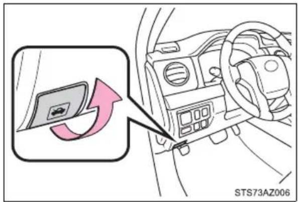
2 Pull up the auxiliary catch lever and lift the hood.
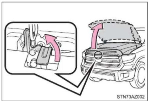

WARNING
■Pre-driving check
Check that the hood is fully closed and locked. If the hood is not locked properly, it may open while the vehicle is in motion and cause an accident, which may result in death or serious injury.
Engine compartment
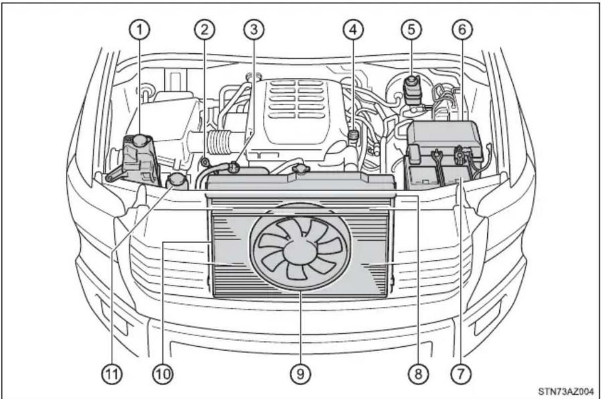
① Washer fluid tank ( P. 425)
② Engine oil level dipstick
(→P. 416)
③ Engine coolant reservoir
(→P. 418)
④ Engine oil filler cap ( P. 417)
⑤ Brake fluid reservoir
(→P. 420)
⑥ Fuse box ( P. 454)
⑦ Battery ( P. 422)
⑧ Radiator ( P. 420)
⑨ Cooling fan
⑩ Condenser ( P. 420)
⑪ Power steering fluid reservoir ( P. 421)
Engine oil
With the engine at operating temperature and turned off, check the oil level on the dipstick.
■ Checking the engine oil
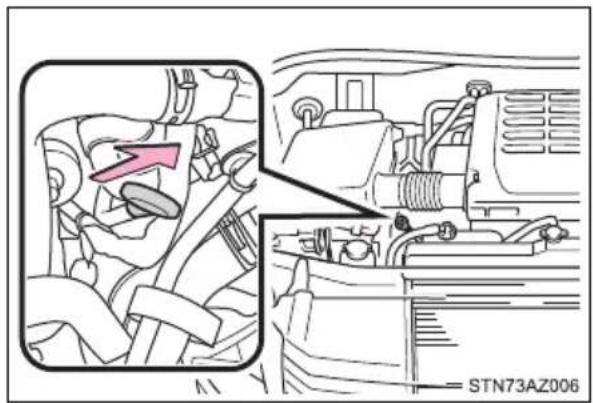
1 Park the vehicle on level ground. After warming up the engine and turning it off, wait more than 5 minutes for the oil to drain back into the bottom of the engine.
2 Holding a rag under the end, pull the dipstick out.
3 Wipe the dipstick clean.
4 Reinsert the dipstick fully.
5 Holding a rag under the end, pull the dipstick out and check the oil level.
① Low
② Normal
③ Excessive
The shape of the dipstick may differ depending on the type of vehicle or engine.
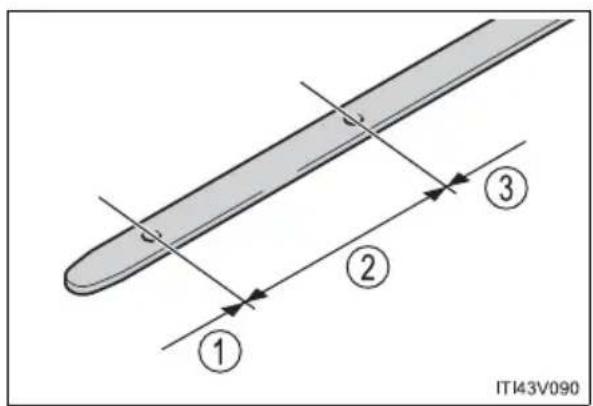
6 Wipe the dipstick and reinsert it fully.
■Adding engine oil
If the oil level is below or near the low level mark, add engine oil of the same type as that already in the engine.
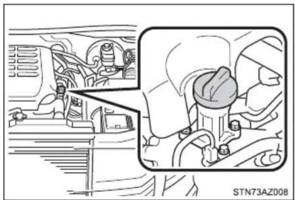
natural_image
Technical diagram showing engine compartment and valve assembly (no text or labels)Make sure to check the oil type and prepare the items needed before adding oil.
| Engine oil selection → | P. 543 |
| Oil quantity (Low → Full) | 1.6 qt. (1.5 L, 1.3 Imp.qt.) |
| Items Clean funnel |
1 Remove the oil filler cap by turning it counterclockwise.
2 Add engine oil slowly, checking the dipstick.
3 Install the oil filler cap by turning it clockwise.
■Engine oil consumption
A certain amount of engine oil will be consumed while driving. In the following situations, oil consumption may increase, and engine oil may need to be refilled in between oil maintenance intervals.
- When the engine is new, for example directly after purchasing the vehicle or after replacing the engine
● If low quality oil or oil of an inappropriate viscosity is used - When driving at high engine speeds or with a heavy load, when towing, or when driving while accelerating or decelerating frequently
- When leaving the engine idling for a long time, or when driving frequently through heavy traffic

WARNING
■Used engine oil
● Used engine oil contains potentially harmful contaminants which may cause skin disorders such as inflammation and skin cancer, so care should be taken to avoid prolonged and repeated contact. To remove used engine oil from your skin, wash thoroughly with soap and water.
- Dispose of used oil and filters only in a safe and acceptable manner. Do not dispose of used oil and filters in household trash, in sewers or onto the ground.
Call your Toyota dealer, service station or auto parts store for information concerning recycling or disposal.
●Do not leave used engine oil within the reach of children.

NOTICE
■To prevent serious engine damage
Check the oil level on a regular basis.
■When replacing the engine oil
● Be careful not to spill engine oil on the vehicle components.
● Avoid overfilling, or the engine could be damaged.
- Check the oil level on the dipstick every time you refill the vehicle.
- Be sure the engine oil filler cap is properly tightened.
Engine coolant
The coolant level is satisfactory if it is between the "FULL" and "LOW" lines on the reservoir when the engine is cold.
① Reservoir cap
② “FULL” line
③ “LOW” line
If the level is on or below the "LOW" line, add coolant up to the "FULL" line. (→P. 529)
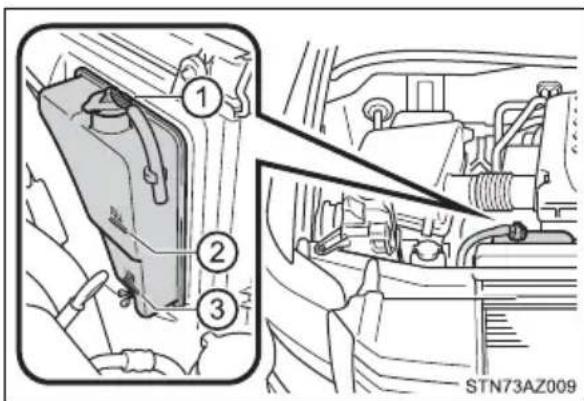
Coolant selection
Only use “Toyota Super Long Life Coolant” or a similar high quality ethylene glycol based non-silicate, non-amine, non-nitrite, and non-borate coolant with long-life hybrid organic acid technology.
U.S.A.:
"Toyota Super Long Life Coolant" is a mixture of 50% coolant and 50% deionized water. (Minimum temperature: -31°F [-35°C])
Canada:
"Toyota Super Long Life Coolant" is a mixture of 55% coolant and 45% deionized water. (Minimum temperature: -44°F [-42°C])
For more details about coolant, contact your Toyota dealer.
If the coolant level drops within a short time of replenishing
Visually check the radiator, hoses, engine coolant reservoir cap, drain cock and water pump.
If you cannot find a leak, have your Toyota dealer test the cap and check for leaks in the cooling system.

WARNING
■When the engine is hot
Do not remove the radiator cap.(→P. 531)
The cooling system may be under pressure and may spray hot coolant if the cap is removed, causing serious injuries, such as burns.

NOTICE
■When adding coolant
Coolant is neither plain water nor straight antifreeze. The correct mixture of water and antifreeze must be used to provide proper lubrication, corrosion protection and cooling. Be sure to read the antifreeze or coolant label.
If you spill coolant
Be sure to wash it off with water to prevent it from damaging parts or paint.
Radiator and condenser
Check the radiator and condenser and clear away any foreign objects. If either of the above parts is extremely dirty or you are not sure of their condition, have your vehicle inspected by your Toyota dealer.

WARNING
■When the engine is hot
Do not touch the radiator or condenser as they may be hot and cause serious injuries, such as burns.
Brake fluid
- Checking fluid level
The brake fluid level should be between the "MAX" and "MIN" lines on the tank.
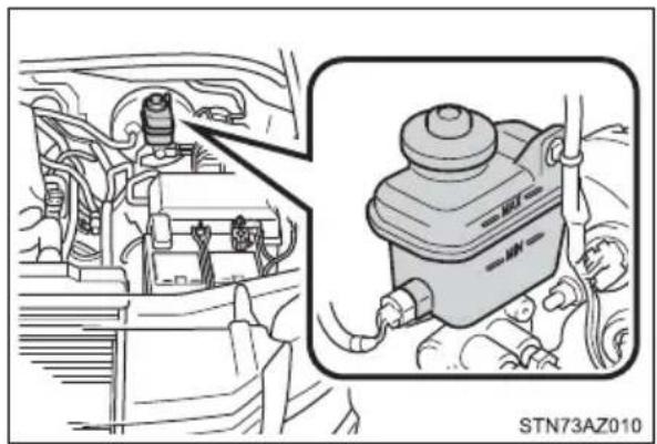
natural_image
Technical diagram showing engine compartment and motor assembly (no text or symbols)■ Adding fluid
Make sure to check the fluid type and prepare the necessary item.
| Fluid type FMVSS No. | 116 DOT 3 or SAE J1703 brake fluid |
| Items Clean funnel |
■Brake fluid can absorb moisture from the air
Excess moisture in the brake fluid can cause a dangerous loss of braking efficiency. Use only newly opened brake fluid.

WARNING
■When filling the reservoir
Take care as brake fluid can harm your hands and eyes and damage painted surfaces.
If fluid gets on your hands or in your eyes, flush the affected area with clean water immediately.
If you still experience discomfort, see a doctor.

NOTICE
If the fluid level is low or high
It is normal for the brake fluid level to go down slightly as the brake pads wear out or when the fluid level in the accumulator is high.
If the reservoir needs frequent refilling, there may be a serious problem.
Power steering fluid
Fluid level
The fluid level should be within the appropriate range.
① Full (when cold)
② Add fluid (when cold)
③ Full (when hot)
④ Add fluid (when hot)
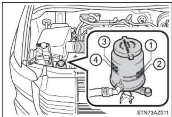
Hot: Vehicle has been driven around 50 mph (80 km/h) for 20 minutes, or slightly longer in frigid temperatures. (Fluid temperature, 140°F - 175°F [60°C - 80°C])
Cold: Engine has not been run for about 5 hours. (Room temperature, 50^ - 85^ [10°C - 30°C])
■ Checking the fluid level
Make sure to check the fluid type and prepare the necessary items.
| Fluid type Automatic transmission fluid DEXRON ^ II or III |
| Items Rag or paper, clean funnel (only for adding fluid) |
1 Clean all dirt off the reservoir.
2 Remove the cap by turning it counterclockwise.
3 Wipe the dipstick clean.
4 Reinstall the cap and remove it again.
5 Check the fluid level.

WARNING
■ Checking the fluid level
Take care, as the reservoir may be hot.

NOTICE
When adding fluid
Avoid overfilling, or the power steering may be damaged.
■After replacing the reservoir cap
Check the steering box case, vane pump and hose connections for leaks or damage.
Battery
Check the battery as follows:
Battery exterior
Make sure that the battery terminals are not corroded and that there are no loose connections, cracks, or loose clamps.
① Terminals
② Hold-down clamp
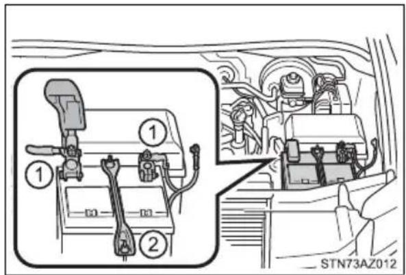
Before recharging
When recharging, the battery produces hydrogen gas which is flammable and explosive. Therefore, observe the following before recharging:
- If recharging with the battery installed on the vehicle, be sure to disconnect the ground cable.
● Make sure the power switch on the charger is off when connecting and disconnecting the charger cables to the battery.
■ After recharging/reconnecting the battery (vehicles with a smart key system)
The engine may not start. Follow the procedure below to initialize the system.
1 Shift the shift lever to P.
2 Open and close any of the doors.
3 Restart the engine.
- Unlocking the doors using the smart key system may not be possible immediately after reconnecting the battery. If this happens, use the wireless remote control or the mechanical key to lock/unlock the doors.
- Start the engine with the engine switch in ACC. The engine may not start when the engine switch turned from off. However, the engine will operate normally from the second attempt.
- The engine switch mode is recorded by the vehicle. If the battery is reconnected, the vehicle will return the engine switch mode to the status it was in before the battery was disconnected. Make sure to turn off the engine before disconnect the battery. Take extra care when connecting the battery if the engine switch mode prior to discharge is unknown.
If the system will not start even after multiple attempts, contact your Toyota dealer.

WARNING
■Chemicals in the battery
Batteries contain poisonous and corrosive sulfuric acid and may produce hydrogen gas which is flammable and explosive. To reduce the risk of death or serious injury, take the following precautions while working on or near battery:
- Do not cause sparks by touching the battery terminals with tools.
●Do not smoke or light a match near the battery.
●Avoid contact with eyes, skin and clothes.
●Never inhale or swallow electrolyte.
●Wear protective safety glasses when working near the battery. - Keep children away from the battery.
■Where to safely charge the battery
Always charge the battery in an open area. Do not charge the battery in a garage or closed room where there is insufficient ventilation.
■How to recharge the battery
Only perform a slow charge (5 A or less). The battery may explode if charged at a quicker rate.
Emergency measures regarding electrolyte
●If electrolyte gets in your eyes
Flush your eyes with clean water for at least 15 minutes and get immediate medical attention. If possible, continue to apply water with a sponge or cloth while traveling to the nearest medical facility.
- If electrolyte gets on your skin
Wash the affected area thoroughly. If you feel pain or burning, get medical attention immediately.
- If electrolyte gets on your clothes
It can soak through clothing on to your skin. Immediately take off the clothing and follow the procedure above if necessary.
- If you accidentally swallow electrolyte
Drink a large quantity of water or milk. Get emergency medical attention immediately.

NOTICE
■When recharging the battery
Never recharge the battery while the engine is running. Also, be sure all accessories are turned off.
Washer fluid
Add washer fluid in the following situations:
●A washer does not work.
●The warning message appears on the display.
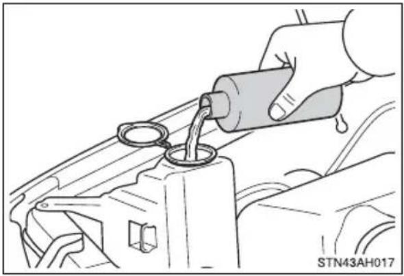
natural_image
Illustration of a hand pouring liquid into a car engine component (no text or symbols)
WARNING
■When adding washer fluid
Do not add washer fluid when the engine is hot or running as washer fluid contains alcohol and may catch fire if spilled on the engine, etc.

NOTICE
Do not use any fluid other than washer fluid
Do not use soapy water or engine antifreeze instead of washer fluid.
Doing so may cause streaking on the vehicle's painted surfaces, as well as damaging the pump leading to problems of the washer fluid not spraying.
Diluting washer fluid
Dilute washer fluid with water as necessary.
Refer to the freezing temperatures listed on the label of the washer fluid bottle.
Tires
Replace or rotate tires in accordance with maintenance schedules and treadwear.
Checking tires
Check if the treadwear indicators are showing on the tires. Also check the tires for uneven wear, such as excessive wear on one side of the tread.
Check the spare tire condition and pressure if not rotated.
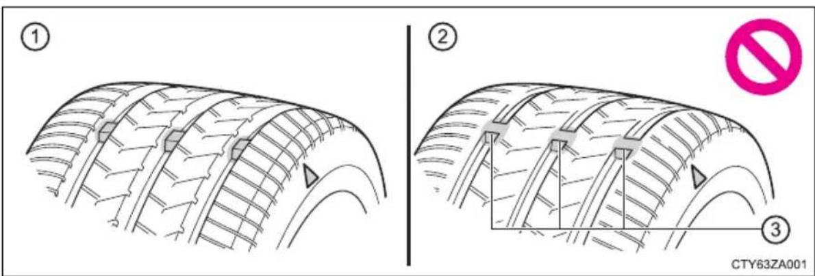
① New tread
② Worn tread
③ Treadwear indicator
The location of treadwear indicators is shown by a "TWI" or "Δ" mark, etc., molded into the sidewall of each tire.
Replace the tires if the treadwear indicators are showing on a tire.
Tire rotation
Rotate the tires in the order shown.
To equalize tire wear and extend tire life, Toyota recommends that tire rotation is carried out at the same interval as tire inspection.
Do not fail to initialize the tire pressure warning system after tire rotation.
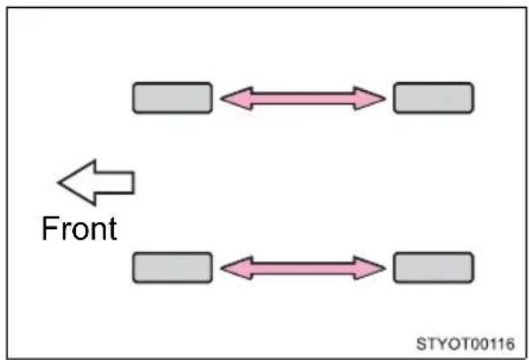
flowchart
graph LR
    A[" "] <--> B[" "]
    C[" "] <--> D[" "]
    E[" "] <--> F[" "]
    G[" "] <--> H[" "]
    I[" "] <--> J[" "]
    K[" "] <--> L[" "]
    M[" "] <--> N[" "]
    O[" "] <--> P[" "]
    Q[" "] <--> R[" "]
    S[" "] <--> T[" "]
    U[" "] <--> V[" "]
    W[" "] <--> X[" "]
    Y[" "] <--> Z[" "]
    AA[" "] <--> AB[" "]
    AC[" "] <--> AD[" "]
    AE[" "] <--> AF[" "]
    AG[" "] <--> AH[" "]
    AI[" "] <--> AJ[" "]
    AK[" "] <--> AL[" "]
    AM[" "] <--> AN[" "]
    AO[" "] <--> AP[" "]
    AQ[" "] <--> AR[" "]
    AS[" "] <--> AT[" "]
    AU[" "] <--> AV[" "]
    AW[" "] <--> AX[" "]
    AY[" "] <--> AZ[" "]
    BA[" "] <--> BB[" "]
    BC[" "] <--> BD[" "]
    BE[" "] <--> BF[" "]
    BG[" "] <--> BH[" "]
    BI[" "] <--> BJ[" "]
    BK[" "] <--> BL[" "]
    BM[" "] <--> BN[" "]
    BO[" "] <--> BP[" "]
    BP[" "] <--> BPB[" "]
    BPB[" "] <--> BPC[" "]
    BPC[" "] <--> BPD[" "]
    BPD[" "] <--> BPE[" "]
    BPE[" "] <--> BPF[" "]
    BPF[" "] <--> BPG[" "]
    BPG[" "] <--> BPH[" "]
    BPH[" "] <--> BPI[" "]
    BPI[" "] <--> BPJ[" "]
    BPJ[" "] <--> BPK[" "]
    BPK[" "] <--> BPL[" "]
    BPL[" "] <--> BPM[" "]
    BPM[" "] <--> BPN[" "]
    BPN[" "] <--> BPO[" "]
    BPO[" "] <--> BPP[" "]
    BPP[" "] <--> BPQ[" "]
    BPQ[" "] <--> BPR[" "]
    BPR[" "] <--> BPS[" "]
    BPS[" "] <--> BPT[" "]
    BPT[" "] <--> BPU[" "]
    BPU[" "] <--> BPV[" "]
    BPV[" "] <--> BPW[" "]
    BPW[" "] <--> BPX[" "]
    BPX[" "] <--> BPY[" "]
    BPY[" "] <--> BPZ[" "]
    BPZ[" "] <--> BPYB[" "]
    BPYB[" "]
Tire pressure warning system
Your vehicle is equipped with a tire pressure warning system that uses tire pressure warning valves and transmitters to detect low tire inflation pressure before serious problems arise.
● The tire pressure detected by the tire pressure warning system can be displayed on the multi-information display.
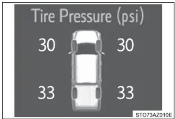
- If the tire pressure drops below a predetermined level, the driver is warned by a screen display and a warning light.
◆Installing tire pressure warning valves and transmitters
When replacing tires or wheels, tire pressure warning valves and transmitters must also be installed.
When new tire pressure warning valves and transmitters are installed, new ID codes must be registered in the tire pressure warning computer and the tire pressure warning system must be initialized.
◆Initializing the tire pressure warning system
■ The tire pressure warning system must be initialized in the following circumstances:
●When rotating the tires.
- When the tire inflation pressure is changed such as when changing tire size. (When there are multiple specified pressures)
● After registering the ID codes. (→P. 429)
When the tire pressure warning system is initialized, the current tire inflation pressure is set as the benchmark pressure.
■How to initialize the tire pressure warning system
1 Park the vehicle in a safe place and turn the engine switch off. Initialization cannot be performed while the vehicle is moving.
2 Adjust the tire inflation pressure to the specified cold tire inflation pressure level. (→P. 548)
Make sure to adjust the tire pressure to the specified cold tire inflation pressure level. The tire pressure warning system will operate based on this pressure level.
3 Turn the engine switch to ON.
4 Press and hold the tire pressure warning reset switch until the tire pressure warning light blinks 3 times.
A message is displayed on the multi-information display. Also, “--” is displayed for inflation pressure of each tir multi-information display while the tire pressure warning sys- tem determines the position.
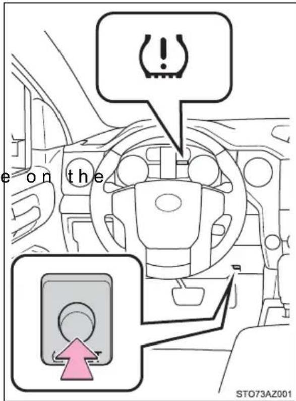
5 Drive straight (with occasional left and right turns) at approximately 25 mph (40 km/h) or more for approximately 10 to 30 minutes.
Initialization is complete when the position of each tire is determined and the inflation pressure of each tire is displayed on the multi-information display.
Initialization may take longer than approximately 30 minutes in certain situations, such as when the vehicle is stopped for a long time at traffic lights, etc. ( P. 434)
◆Registering ID codes
Every tire pressure warning valve and transmitter has a unique ID code. When replacing a tire pressure warning valve and transmitter, it is necessary to register the ID codes.
To register the ID codes, perform the following procedure:
1 Press the tire pressure warning reset switch 3 times until the tire pressure warning light blinks slowly 3 times.
Then a message will be displayed on multi-information display. When registration is being performed, the tire pressure warning light will blink for approximately 1 minute then illuminate and “--” will be displayed for the inflation pressure of each tire on the multi-information display.
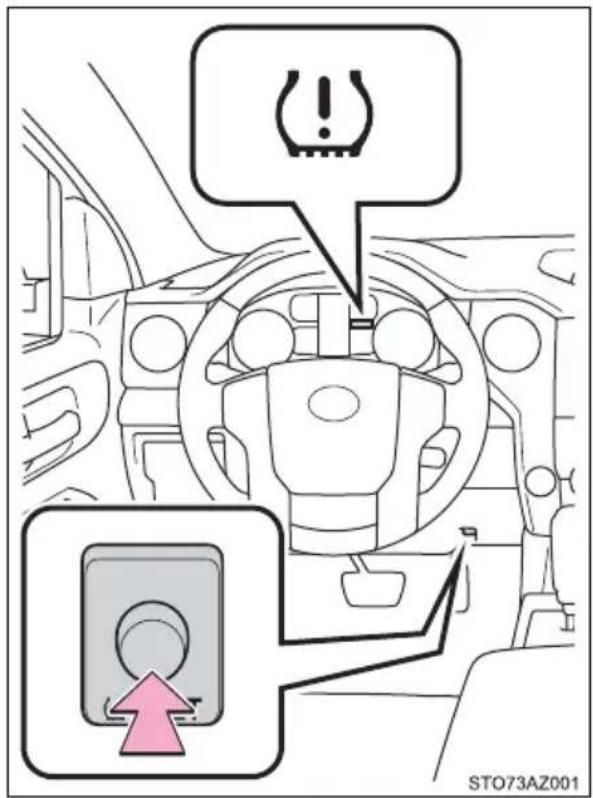
2 Drive straight (with occasional left and right turns) at approximately 25 mph (40 km/h) or more for approximately 10 to 30 minutes.
Registration is complete when the tire pressure warning light turns off and the inflation pressure of each tire is displayed on the multi-information display.
Registration may take longer than approximately 30 minutes in certain situations, such as when the vehicle is stopped for a long time at traffic lights, etc. ( P. 434)
After registering the ID codes, make sure to initialize the tire pressure warning system. ( P. 427)
- When to replace your vehicle’s tires
Tires should be replaced if:
● The treadwear indicators are showing on a tire.
- You have tire damage such as cuts, splits, cracks deep enough to expose the fabric, and bulges indicating internal damage
● A tire goes flat repeatedly or cannot be properly repaired due to the size or location of a cut or other damage
If you are not sure, consult with your Toyota dealer.
■When replacing the tires and wheels
If the ID code of the tire pressure warning valve and transmitter is not registered, the tire pressure warning system will not work properly. After driving for about 20 minutes, the tire pressure warning light blinks for 1 minute and stays on to indicate a system malfunction.
Tire life
Any tire over 6 years old must be checked by a qualified technician even if it has seldom or never been used or damage is not obvious.
■Routine tire inflation pressure checks
The tire pressure warning system does not replace routine tire inflation pressure checks. Make sure to check tire inflation pressure as part of your routine of daily vehicle checks.
■Maximum load of tire
Check that the number given by dividing the maximum load by 1.10 of the replacement tire is greater than 1/2 of the Gross Axle Weight Ratings (GAWR) of either the front axle or the rear axle, whichever is greater.
For the GAWR, see the Certification Label. For the maximum load of the tire, see the load limit at maximum cold tire inflation pressure mentioned on the sidewall of the tire. ( P. 554)

natural_image
Line drawing of a car seat with a double door and arrow indicating fastening (no text or symbols)Tire types
●Summer tires
Summer tires are high-speed performance tires best suited to highway driving under dry conditions. Since summer tires do not have the same traction performance as snow tires, summer tires are inadequate for driving on snow-covered or icy roads. For driving on snow-covered roads or icy roads, the use of snow tires is recommended. When installing snow tires, be sure to replace all four tires.
●All season tires
All season tires are designed to provide better traction in snow and to be adequate for driving in most winter conditions as well as for use year-round. All season tires, however, do not have adequate traction performance compared with snow tires in heavy or loose snow. Also, all season tires fall short in acceleration and handling performance compared with summer tires in highway driving.
●Snow tires
For driving on snow-covered roads or icy roads, we recommend using snow tires. If you need snow tires, select tires of the same size, construction and load capacity as the originally installed tires. Since your vehicle has radial tires as original equipment, make sure your snow tires also have radial construction. Do not install studded tires without first checking local regulations for possible restrictions. Snow tires should be installed on all wheels. (→P. 331)
■Initializing the tire pressure warning system
Initialize the system with the tire inflation pressure adjusted to the specified level.
If the tread on snow tires wears down below 0.16 in. (4 mm)
The effectiveness of the tires as snow tires is lost.
■ Situations in which the tire pressure warning system may not operate properly
- In the following cases, the tire pressure warning system may not operate properly.
- If non-genuine Toyota wheels are used.
- A tire has been replaced with a tire that is not an OE (Original Equipment) tire.
- A tire has been replaced with a tire that is not of the specified size.
- Tire chains, etc., are equipped.
- An auxiliary-supported run-flat tire is equipped.
- If a window tint that affects the radio wave signals is installed.
- If there is a lot of snow or ice on the vehicle, particularly around the wheels or wheel housings.
- If the tire inflation pressure is extremely higher than the specified level.
- If wheel without the tire pressure warning valve and transmitter is used.
- If the ID code on the tire pressure warning valves and transmitter is not registered in the tire pressure warning computer.
●Performance may be affected in the following situations.
- Near a TV tower, electric power plant, gas station, radio station, large display, airport or other facility that generates strong radio waves or electrical noise
- When carrying a portable radio, cellular phone, cordless phone or other wireless communication device
If tire position information is not correctly displayed due to the radio wave conditions, the display may be corrected by driving and changing the radio wave conditions.
- When the vehicle is parked, the time taken for the warning to start or go off could be extended.
- When tire inflation pressure declines rapidly for example when a tire has burst, the warning may not function.
■The initialization operation
● Make sure to carry out initialization after adjusting the tire inflation pressure.
Also, make sure the tires are cold before carrying out initialization or tire inflation pressure adjustment.
- If you have accidentally turned the engine switch off during initialization, it is not necessary to press the reset switch again as initialization will restart automatically when the engine switch has been turned to ON for the next time.
- If you accidentally press the reset switch when initialization is not necessary, adjust the tire inflation pressure to the specified level when the tires are cold, and conduct initialization again.
● While the position of each tire is being determined and the inflation pressures are not being displayed on the multi-information display, if the inflation pressure of a tire drops, the tire pressure warning light will come on.
■Warning performance of the tire pressure warning system
The warning of the tire pressure warning system will change in accordance with the conditions under which it was initialized. For this reason, the system may give a warning even if the tire pressure does not reach a low enough level, or if the pressure is higher than the pressure that was adjusted to when the system was initialized.
■ When initialization of the tire pressure warning system has failed
Initialization may take longer to complete if the vehicle is driven on an unpaved road. When performing initialization, drive on a paved road if possible. Depending on the driving environment and condition of the tires, initialization will be completed in approximately 10 to 30 minutes. If initialization is not complete after driving approximately 10 to 30 minutes, continue driving for a while.
If the inflation pressure of each tire is not displayed after driving for approximately 1 hour, perform the following procedure.
- Park the vehicle in a safe place for approximately 20 minutes. Then drive straight (with occasional left and right turns) at approximately 25 mph (40 km/h) or more for approximately 10 to 30 minutes.
However, in the following situations, the tire inflation pressure will not be recorded and the system will not operate properly. Perform initialization again.
- When operating the tire pressure warning reset switch, the tire pressure warning light does not blink 3 times.
● After performing initialization, the tire pressure warning light blinks for 1 minute then stays on while driving about 20 minutes.
If the inflation pressure of each tire is still not displayed, have the vehicle inspected by your Toyota dealer.
■Tire pressure warning system certification
For vehicles sold in the U.S.A.
FCC ID: PAXPMVC015
NOTE
This device complies with part 15 of the FCC Rules. Operation is subject to the following two conditions:
(1) This device may not cause harmful interference, and (2) this device must accept any interference received, including interference that may cause undesired operation.
FCC WARNING
Changes or modifications not expressly approved by the party responsible for compliance could void the user's authority to operate the equipment.
FCC ID: PAXPMVE000
NOTE
This device complies with part 15 of the FCC Rules. Operation is subject to the following two conditions:
(1) This device may not cause harmful interference, and (2) this device must accept any interference received, including interference that may cause undesired operation.
FCC WARNING
Changes or modifications not expressly approved by the party responsible for compliance could void the user's authority to operate the equipment.
FCC ID: PAXPMVE100
NOTE
This device complies with part 15 of the FCC Rules. Operation is subject to the following two conditions:
(1) This device may not cause harmful interference, and (2) this device must accept any interference received, including interference that may cause undesired operation.
FCC WARNING
Changes or modifications not expressly approved by the party responsible for compliance could void the user's authority to operate the equipment.
TRW Automotive
Tire Pressure Monitoring Sensor
FCC ID: GQ4-72T
This device complies with Part 15 of the FCC Rules.
Operation is subject to the following two conditions:
(1) This device may not cause harmful interference, and
(2) This device must accept any interference received, including interference that may cause undesired operation of this device.
WARNING: Changes or modifications not expressly approved by
TRW Automotive U.S. LLC could void the user's authority to operate the equipment.
"Perchlorate Material – special handling may apply, See
www.dtsc.ca.gov/hazardouswaste/perchlorate."
TRW Automotive
Tire Pressure Monitoring Sensor
FCC ID: GQ4-72T
FCC ID: GQ4-49R
This device complies with Part 15 of the FCC Rules.
Operation is subject to the following two conditions:
(1) This device may not cause harmful interference, and
(2) This device must accept any interference received, including interference that may cause undesired operation.
Le present appareil est conforme aux CNR d'Industrie Canada applicable aux appareils radio exempts de licence.
WARNING: Changes or modifications not expressly approved by TRW Automotive U.S. LLC could void the user's
authority to operate the equipment.
The term "IC:" before the radio certification number only signifies that Industry Canada technical specifications
were met.
For vehicles sold in Canada
Model: PMV-E000
Model:PMV-C015
NOTE
This device complies with Industry Canada licence-exempt RSS standard(s). Operation is subject to the following two conditions: (1) this device may not cause interference, and (2) this device must accept any interference, including interference that may cause undesired operation of the device.
NOTE
This device complies with Industry Canada licence-exempt RSS standard(s). Operation is subject to the following two conditions: (1) this device may not cause interference, and (2) this device must accept any interference, including interference that may cause undesired operation of the device.
NOTE
This device complies with Part 15 of the FCC Rules and with RSS Standards of Industry Canada.
Operation is subject to the following two conditions:
(1) This device may not cause harmful interference, and
(2) This device must accept any interference received, including interference that may cause undesired operation.
Le present appareil est conforme aux CNR d'Industrie Canada applicable aux appareils radio exempts de licence.
WARNING: Changes or modifications not expressly approved by TRW Automotive U.S. LLC could void the user's authority to operate the equipment.
The term "IC:" before the radio certification number only signifies that Industry Canada technical specifications were met.

WARNING
■When inspecting or replacing tires
Observe the following precautions to prevent accidents.
Failure to do so may cause damage to parts of the drive train as well as dangerous handling characteristics, which may lead to an accident resulting in death or serious injury.
- Do not mix tires of different makes, models or tread patterns.
Also, do not mix tires of remarkably different treadwear. - Do not use tire sizes other than those recommended by Toyota.
- Do not mix differently constructed tires (radial, bias-belted or bias-ply tires).
- Do not mix summer, all season and snow tires.
- Do not use tires that have been used on another vehicle.
Do not use tires if you do not know how they were used previously.
■When initializing the tire pressure warning system
Do not operate the tire pressure warning reset switch without first adjusting the tire inflation pressure to the specified level. Otherwise, the tire pressure warning light may not come on even if the tire inflation pressure is low, or it may come on when the tire inflation pressure is actually normal.

NOTICE
■ Repairing or replacing tires, wheels, tire pressure warning valves, transmitters and tire valve caps
- When removing or fitting the wheels, tires or the tire pressure warning valves and transmitters, contact your Toyota dealer as the tire pressure warning valves and transmitters may be damaged if not handled correctly.
● Make sure to install the tire valve caps. If the tire valve caps are not installed, water could enter the tire pressure warning valves and the tire pressure warning valves could be bound. - When replacing tire valve caps, do not use tire valve caps other than those specified. The cap may become stuck.
■ To avoid damage to the tire pressure warning valves and transmitters
When a tire is repaired with liquid sealants, the tire pressure warning valve and transmitter may not operate properly. If a liquid sealant is used, contact your Toyota dealer or other qualified service shop as soon as possible. Make sure to replace the tire pressure warning valve and transmitter when replacing the tire. (→P. 427)
- Driving on rough roads
Take particular care when driving on roads with loose surfaces or pot-holes.
These conditions may cause losses in tire inflation pressure, reducing the cushioning ability of the tires. In addition, driving on rough roads may cause damage to the tires themselves, as well as the vehicle's wheels and body.
If tire inflation pressure of each tire becomes low while driving
Do not continue driving, or your tires and/or wheels may be ruined.
Tire inflation pressure
Tire inflation pressure
The recommended cold tire inflation pressure and tire size are displayed on the tire and loading information label. ( P. 548)
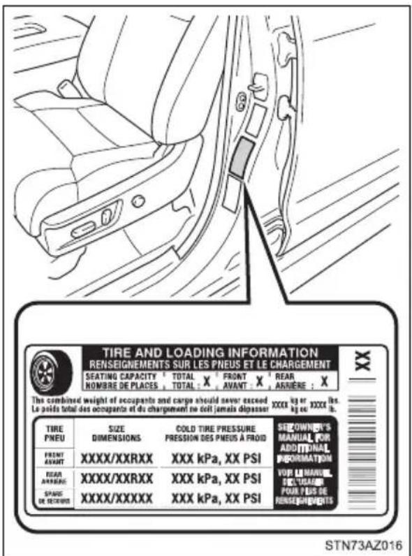
Inspection and adjustment procedure
① Tire valve
② Tire pressure gauge
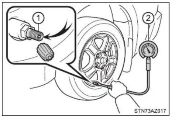
1 Remove the tire valve cap.
2 Press the tip of the tire pressure gauge onto the tire valve.
3 Read the pressure using the gauge gradations.
4 If the tire inflation pressure is not at the recommended level, adjust the pressure.
If you add too much air, press the center of the valve to deflate.
5 After completing the tire inflation pressure measurement and adjustment, apply soapy water to the valve and check for leakage.
6 Put the tire valve cap back on.
■Tire inflation pressure check interval
You should check tire inflation pressure every two weeks, or at least once a month.
Do not forget to check the spare.
■Effects of incorrect tire inflation pressure
Driving with incorrect tire inflation pressure may result in the following:
●Reduced fuel economy
●Reduced driving comfort and poor handling
●Reduced tire life due to wear
●Reduced safety
●Damage to the drive train
If a tire needs frequent inflating, have it checked by your Toyota dealer.
■Instructions for checking tire inflation pressure
When checking tire inflation pressure, observe the following:
- Check only when the tires are cold.
If your vehicle has been parked for at least 3 hours or has not been driven for more than 1 mile or 1.5 km, you will get an accurate cold tire inflation pressure reading.
●Always use a tire pressure gauge.
It is difficult to judge if a tire is properly inflated based only on its appearance. - It is normal for the tire inflation pressure to be higher after driving as heat is generated in the tire. Do not reduce tire inflation pressure after driving.
● Passengers and luggage weight should be placed so that the vehicle is balanced.

WARNING
■Proper inflation is critical to save tire performance
Keep your tires properly inflated.
If the tires are not properly inflated, the following conditions may occur which could lead to an accident resulting in death or serious injury:
Excessive wear
Uneven wear
●Poor handling
● Possibility of blowouts resulting from overheated tires
●Air leaking from between tire and wheel
●Wheel deformation and/or tire damage
● Greater possibility of tire damage while driving (due to road hazards, expansion joints, sharp edges in the road, etc.)

NOTICE
■ When inspecting and adjusting tire inflation pressure
Be sure to put the tire valve caps back on.
If a valve cap is not installed, dirt or moisture may get into the valve and cause an air leak, resulting in decreased tire inflation pressure.
Wheels
If a wheel is bent, cracked or heavily corroded, it should be replaced. Otherwise, the tire may separate from the wheel or cause a loss of handling control.
Wheel selection
When replacing wheels, care should be taken to ensure that they are equivalent to those removed in load capacity, diameter, rim width and inset*.
Replacement wheels are available at your Toyota dealer.
*: Conventionally referred to as "offset".
Toyota does not recommend using the following:
●Wheels of different sizes or types
●Used wheels
●Bent wheels that have been straightened
Aluminum wheel precautions (if equipped)
●Use only Toyota wheel nuts and wrenches designed for use with your aluminum wheels.
- When rotating, repairing or changing your tires, check that the wheel nuts are still tight after driving 1000 miles (1600 km).
- Be careful not to damage the aluminum wheels when using tire chains.
- Use only Toyota genuine balance weights or equivalent and a plastic or rubber hammer when balancing your wheels.
■When replacing wheels
The wheels of your vehicle are equipped with tire pressure warning valves and transmitters that allow the tire pressure warning system to provide advance warning in the event of a loss in tire inflation pressure. Whenever wheels are replaced, tire pressure warning valves and transmitters must be installed. ( P. 427)
■When installing the wheel ornament (on some models)
Align the notch of the wheel and ornament.
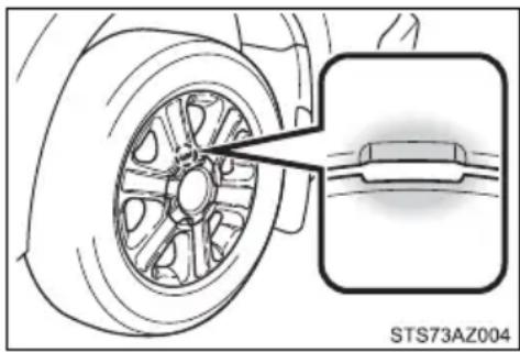
natural_image
Technical illustration of a car wheel assembly with an inset showing a component detail (no text or symbols)
WARNING
■When replacing wheels
- Do not use wheels that are a different size from those recommended in the Owner's Manual, as this may result in a loss of handling control.
● Never use an inner tube in a leaking wheel which is designed for a tubeless tire. Doing so may result in an accident, causing death or serious injury.
■When installing the wheel nuts
- Be sure to install the wheel nuts with the tapered ends facing inward. (→P. 515) Installing the nuts with the tapered ends facing outward can cause the wheel to break and eventually cause the wheel to come off while driving, which could lead to an accident resulting in death or serious injury.
- Never use oil or grease on the wheel bolts or wheel nuts. Oil and grease may cause the wheel nuts to be excessively tightened, leading to bolt or disc wheel damage. In addition, the oil or grease can cause the wheel nuts to loosen and the wheel may fall off, causing an accident and resulting in death or serious injury. Remove any oil grease from the wheel bolts or wheel nuts.
or

NOTICE
■Replacing tire pressure warning valves and transmitters
Because tire repair or replacement may affect the tire pressure warning valves and transmitters, make sure to have tires serviced by your Toyota dealer or other qualified service shop. In addition, make sure to purchase your tire pressure warning valves and transmitters at your Toyota dealer.
- Ensure that only genuine Toyota wheels are used on your vehicle. Tire pressure warning valves and transmitters may not work properly with non-genuine wheels.
Air conditioning filter
The air conditioning filter must be changed regularly to maintain air conditioning efficiency.
Removal method
1 Turn the engine switch off.
2 Open the glove box.
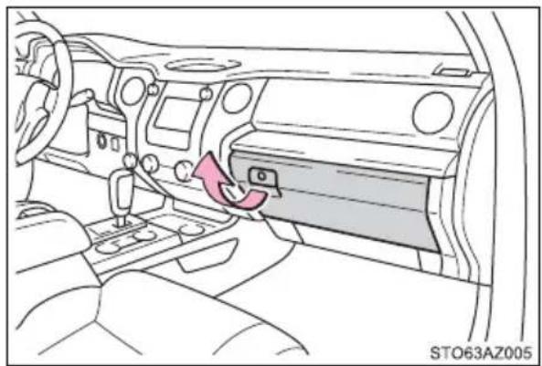
natural_image
Interior view of a car dashboard with steering wheel and air vent (no text or symbols visible)3 Remove the tray.
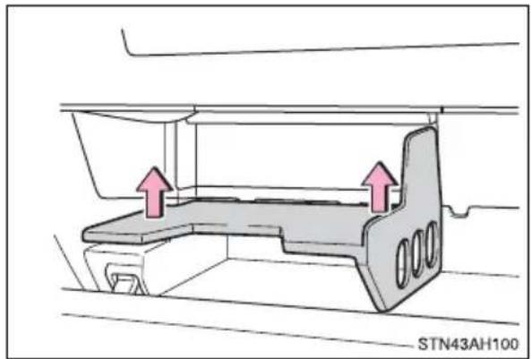
natural_image
Technical line drawing of a mechanical component with two pink arrows indicating upward movement (no text or symbols)4 Remove the cover by sliding up while pulling toward you.
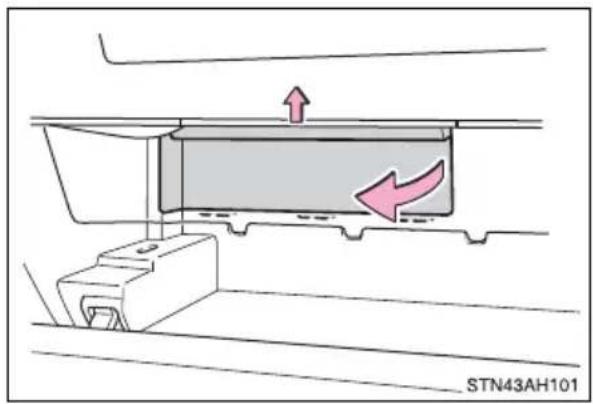
5 Remove the filter cover.
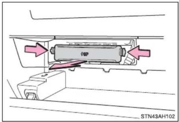
6 Pull the filter out of the filter outlet.
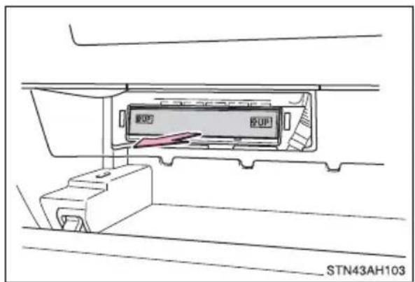
Replacement method
Remove the air conditioning filter and replace it with a new one.
The “↑UP” marks shown on the filter should be pointing up.
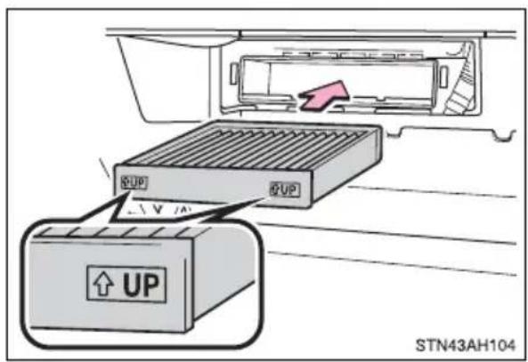
- Checking interval
Inspect and replace the air conditioning filter according to the maintenance schedule. In dusty areas or areas with heavy traffic flow, early replacement may be required. (For scheduled maintenance information, please refer to the "Scheduled Maintenance Guide" or "Owner's Manual Supplement".)
If air flow from the vents decreases dramatically
The filter may be clogged. Check the filter and replace if necessary.

NOTICE
■When using the air conditioning system
Make sure that a filter is always installed.
Using the air conditioning system without a filter may cause damage to the system.
Wireless remote control/electronic key battery\*
Replace the battery with a new one if it is depleted.
You will need the following items:
●Flathead screwdriver
●Small flathead screwdriver
●Lithium battery CR2016 (vehicles without a smart key system), or CR2032 (vehicles with a smart key system)
Replacing the battery
▶ Vehicles without a smart key system
1 Remove the cover.
To prevent damage to the key, cover the tip of the screwdriver with a rag.
To prevent the buttons from being disassembled, face the button surface downward.
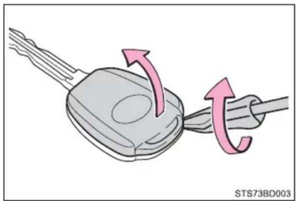
natural_image
Diagram showing a car key being inserted into a cable, with arrows indicating the process (no text or symbols present)2 Remove the module.
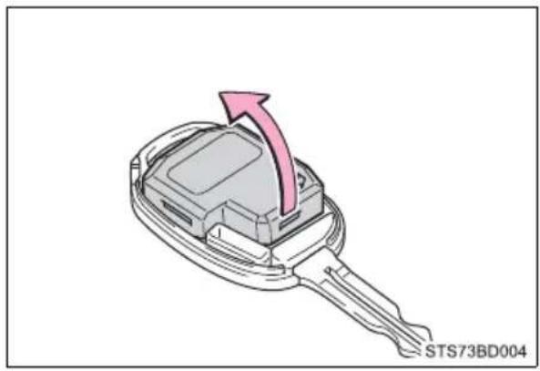
natural_image
3D illustration of a car key with an arrow indicating direction (no text or symbols on the main body)3 Open the case cover using a coin protected with tape, etc., and remove the depleted battery.
Insert a new battery with the “+” terminal facing up.
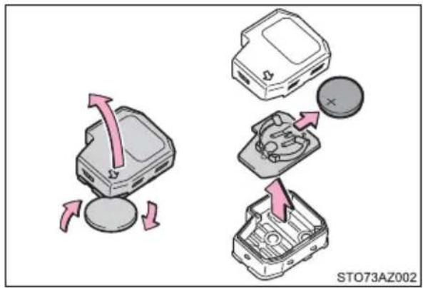
▶ Vehicles with a smart key system
1 Take out the mechanical key.
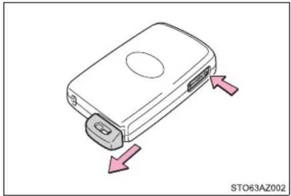
natural_image
Illustration of a device with a handle and two arrows indicating movement or force (no text or symbols on the device itself)2 Remove the cover.
To prevent damage to the key, cover the tip of the screwdriver with a rag.
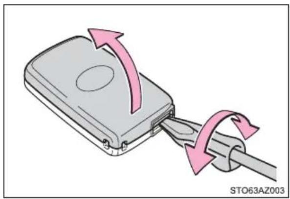
natural_image
Illustration of a USB drive with pink arrows indicating cable movement (no text or symbols)3 Remove the depleted battery.
Insert a new battery with the “+” terminal facing up.
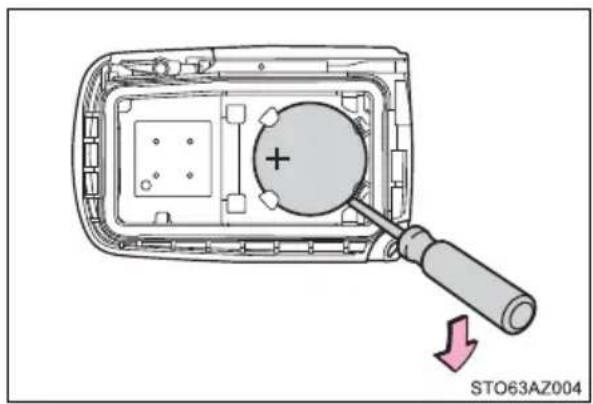
■ Use a CR2016 (vehicles without a smart key system) or CR2032 (vehicles with a smart key system) lithium battery
● Batteries can be purchased at your Toyota dealer, local electrical appliance shops or camera stores.
- Replace only with the same or equivalent type recommended by the manufacturer.
●Dispose of used batteries according to local laws.
If the key battery is depleted
The following symptoms may occur:
● The smart key system (if equipped) and wireless remote control will not function properly.
●The operational range will be reduced.

WARNING
■Removed battery and other parts
Keep away from children. These parts are small and if swallowed by a child, they can cause choking. Failure to do so could result in death or serious injury.
■Certification for the lithium battery
CAUTION: RISK OF EXPLOSION IF BATTERY IS REPLACED BY AN INCORRECT TYPE. DISPOSE OF USED BATTERIES ACCORDING TO THE INSTRUCTIONS

NOTICE
For normal operation after replacing the battery
Observe the following precautions to prevent accidents:
●Always work with dry hands.
Moisture may cause the battery to rust.
- Do not touch or move any other component inside the remote control.
- Do not bend either of the battery terminals.
Checking and replacing fuses
If any of the electrical components do not operate, a fuse may have blown. If this happens, check and replace the fuses as necessary.
1 Turn the engine switch off.
2 Open the fuse box cover.
▶ Engine compartment
Push the tab in and lift the cover off.
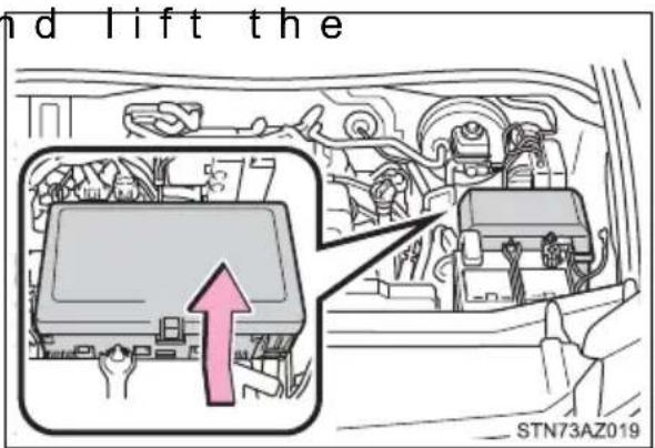
▶ Under the instrument panel Remove the cover.
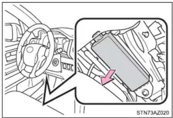
natural_image
Interior view of a car dashboard and steering wheel, showing a close-up of the steering wheel (no text or symbols visible)3 Remove the fuse with the pull-out tool.
Only type A fuse can be removed using the pullout tool.
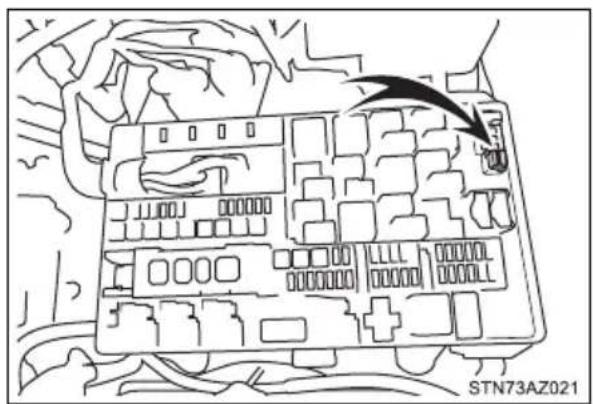
4 Check if the fuse is blown.
① Normal fuse
② Blown fuse
Type A and B:
Replace the blown fuse with a new fuse of an appropriate amperage rating. The amperage rating can be found on the fuse box cover.
Type C:
Contact your Toyota dealer.
▶ Type A ▶ Type B
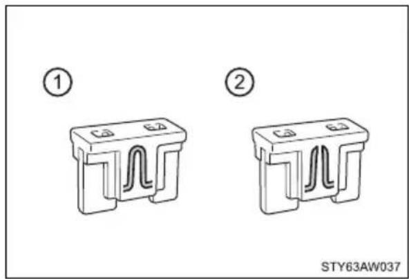
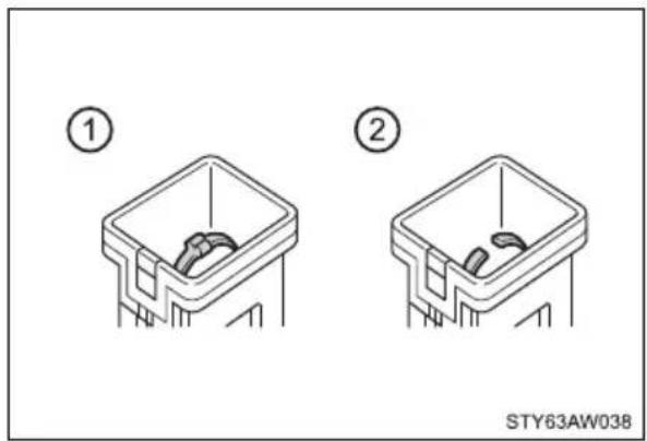
▶ Type C
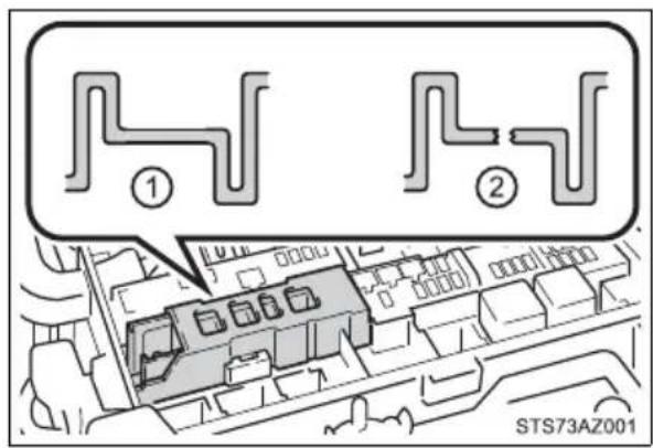
■After a fuse is replaced
- If the lights do not turn on even after the fuse has been replaced, a bulb may need replacement. (→P. 457)
- If the replaced fuse blows again, have the vehicle inspected by your Toyota dealer.
If there is an overload in a circuit
The fuses are designed to blow, protecting the wiring harness from damage.

WARNING
■To prevent system breakdowns and vehicle fire
Observe the following precautions.
Failure to do so may cause damage to the vehicle, and possibly a fire or injury.
● Never use a fuse of a higher amperage rating than that indicated, or use any other object in place of a fuse.
●Always use a genuine Toyota fuse or equivalent.
Never replace a fuse with a wire, even as a temporary fix.
- Do not modify the fuses or fuse boxes.

NOTICE
■ Before replacing fuses
Have the cause of electrical overload determined and repaired by your Toyota dealer as soon as possible.
Light bulbs
You may replace the following bulbs by yourself. The difficulty level of replacement varies depending on the bulb. If necessary bulb replacement seems difficult to perform, contact your Toyota dealer.
For more information about replacing other light bulbs, contact your Toyota dealer.
Preparing for light bulb replacement
Check the wattage of the light bulb to be replaced. (→P. 550)
Bulb locations
Front
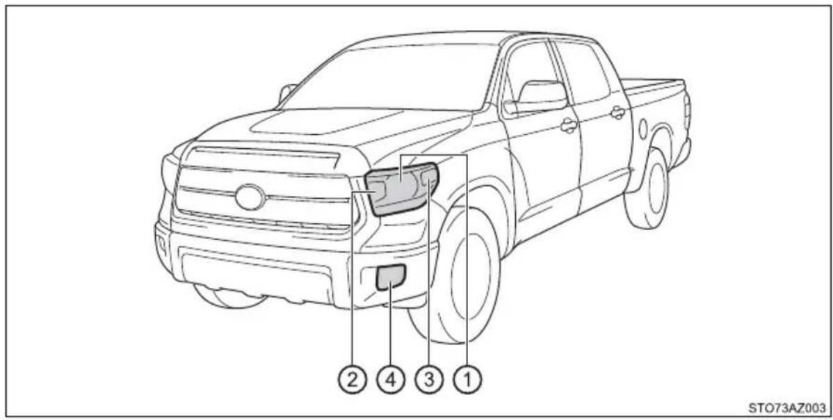
① Headlights (bulb type)
② Front turn signal lights/parking lights (bulb type)
③ Front side marker lights
④ Fog lights (bulb type) (if equipped)
Rear
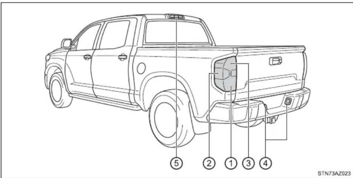
① Stop/tail and rear side marker lights
② Back up lights
③ Rear turn signal lights
④ License plate lights
⑤ High mounted stoplight and cargo lamps
Replacing light bulbs
■Headlights (bulb type)
1 To allow enough working space, turn the steering wheel to the opposite side of the bulb to be replaced.
R e m o v e t h e fender liner clip, and remove the fender liner.
Turn the steering wheel to the left when replacing the right side light bulb, and turn the steering wheel to the right when replacing the left side light bulb.
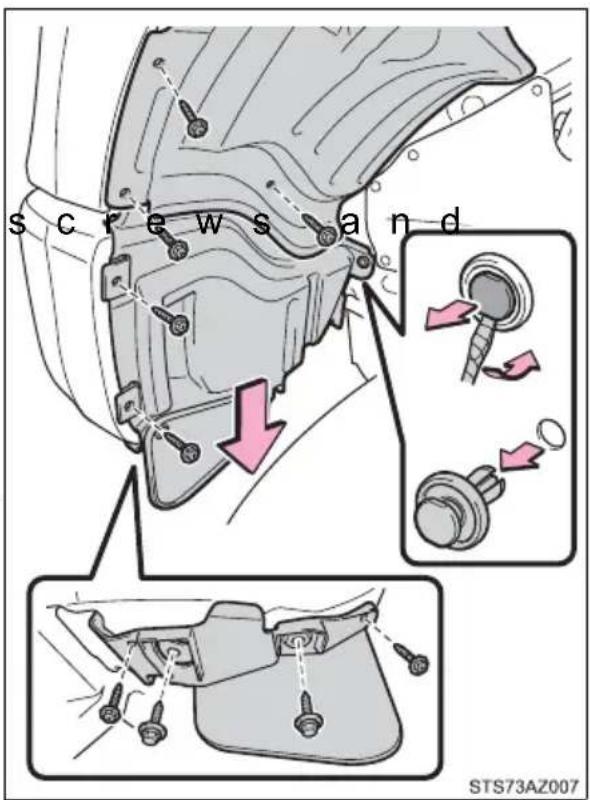
2 Open the fender liner and unplug the connector.
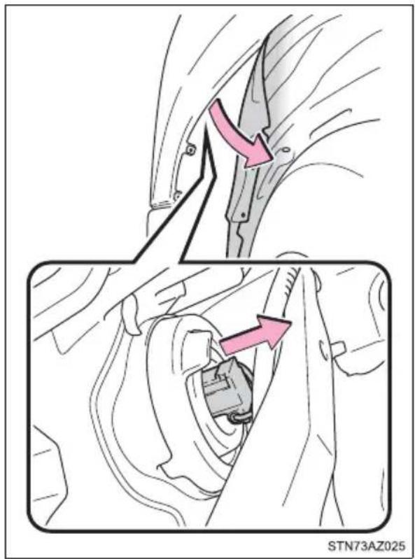
3 Remove the rubber cover.
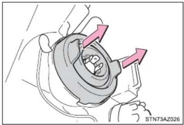
natural_image
Mechanical component diagram showing a rotating housing with directional arrows indicating motion (no text or symbols)4 Release the bulb retaining spring.
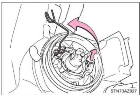
natural_image
Mechanical assembly diagram showing a rotating component with arrows indicating motion direction (no text or symbols)5 Remove the bulb.

natural_image
Mechanical assembly diagram showing a car wheel with a red arrow indicating direction (no text or symbols present)6 Set the new light bulb.
To install a new bulb, align tabs of the bulb with the cutouts of the mounting hole.
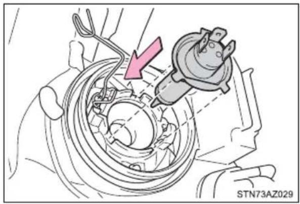
natural_image
Mechanical assembly diagram showing a motor and gear assembly with a pink arrow indicating direction (no text or symbols)7 Install the bulb retaining spring.
8 Install the rubber cover. When installing the rubber cover: P. 471
9 Install the connector.
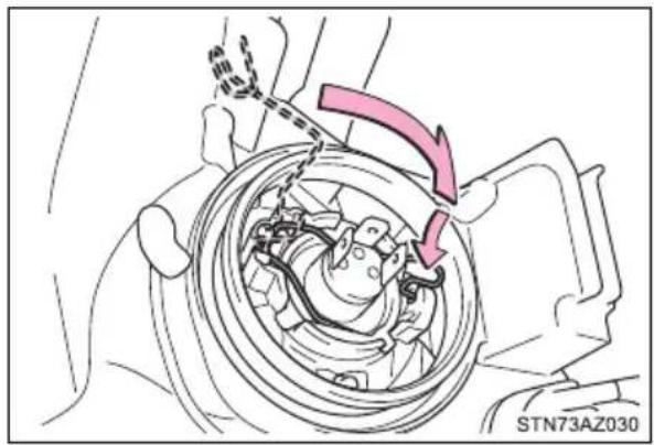
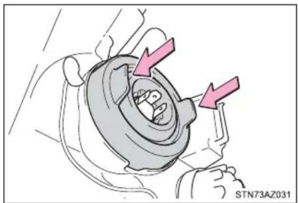
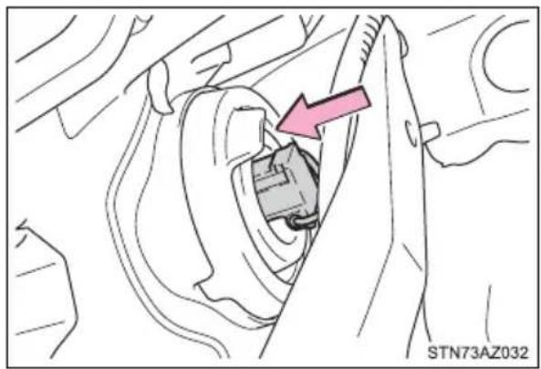
natural_image
Mechanical assembly diagram showing a component inserted into a gear (no text or symbols visible)10 Reinstall the fender liner and install the screws and clip.
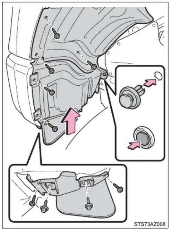
■Front turn signal/parking lights (bulb type headlights)
1 Turn the bulb base counterclockwise.
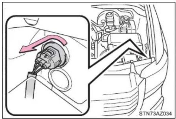
2 Remove the light bulb.
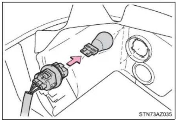
natural_image
Diagram of a car electrical plug inserted into a housing, showing wiring and component placement (no text or symbols)■Front turn signal lights (LED type headlights)
1 Turn the bulb base counterclockwise.
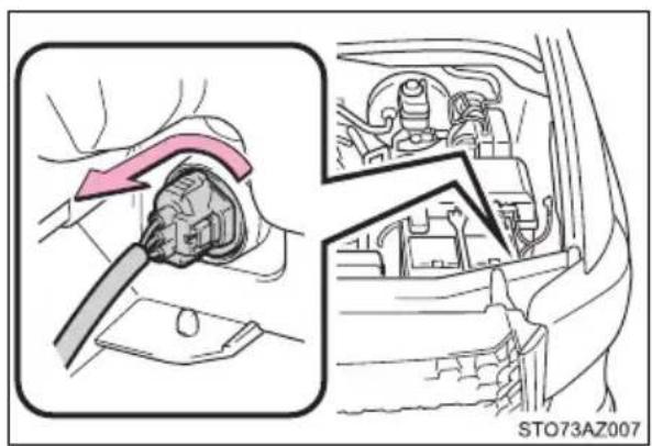
2 Remove the light bulb.
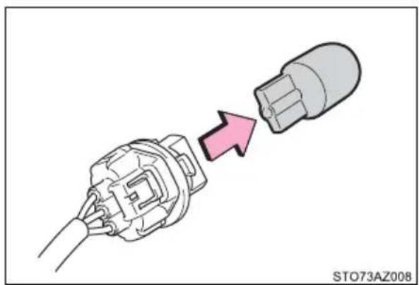
natural_image
Diagram showing a plug being inserted into a terminal block, with a pink arrow indicating the process (no text or symbols present)■Front side marker lights
1 To allow enough working space, turn the steering wheel to the opposite side of the bulb to be replaced. Remove the fender liner clip, and remove the fender liner.
Turn the steering wheel to the left when replacing the right side light bulb, and turn the steering wheel to the right when replacing the left side light bulb.
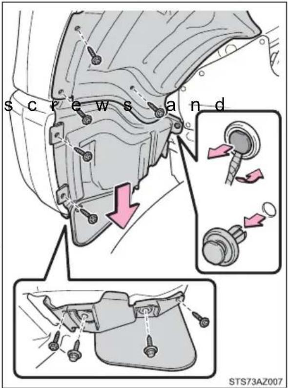
2 Open the fender liner and turn the bulb base counterclockwise.
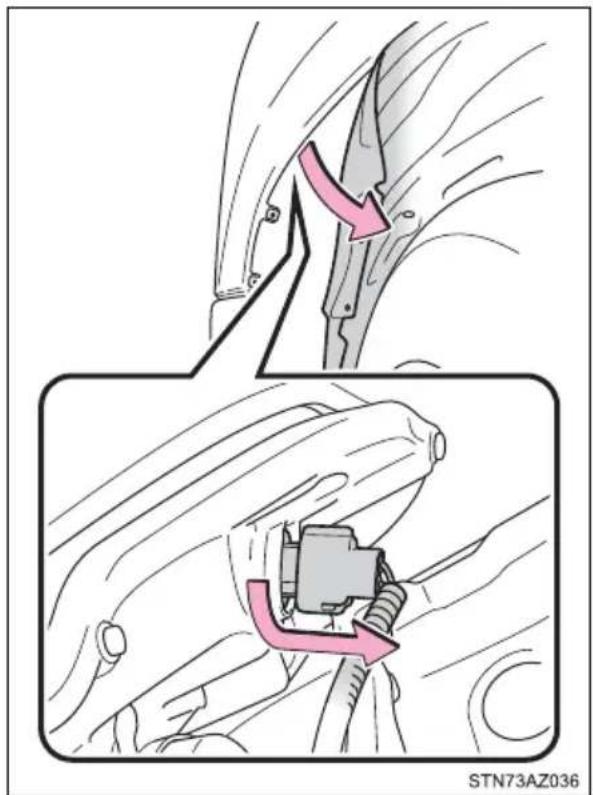
3 Remove the light bulb.
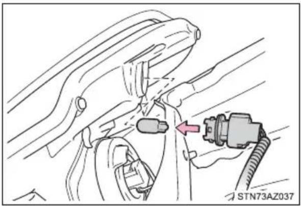
natural_image
Line drawing of a car interior with a plug inserted into the seat, showing mechanical components and wiring (no text or symbols)4 Reinstall the fender liner and install the screws and clip.
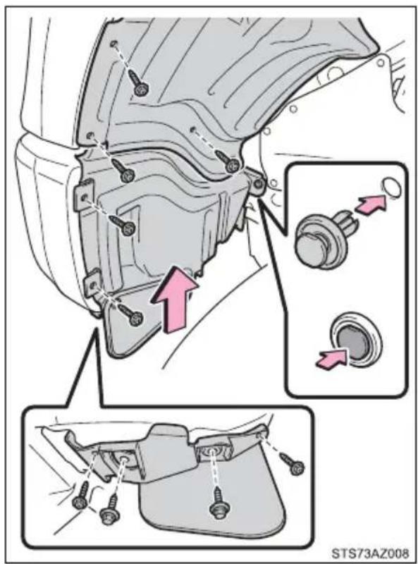
■Front fog lights-bulb type (if equipped)
1 To allow enough working space, turn the steering wheel to the opposite side of the bulb to be replaced. Remove the fender liner clip, and remove the fender liner.
Turn the steering wheel to the left when replacing the right side light bulb, and turn the steering wheel to the right when replacing the left side light bulb.
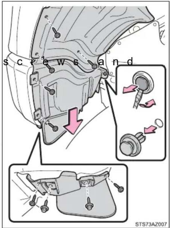
2 Unplug the connector while depressing the lock release.
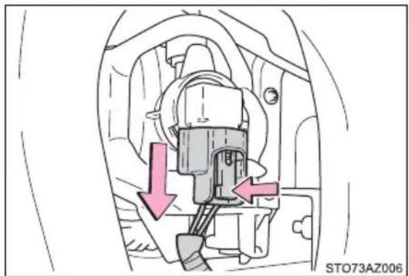
natural_image
Mechanical component diagram showing a valve assembly with two directional arrows indicating movement (no text or symbols present)3 Turn the bulb counterclockwise.
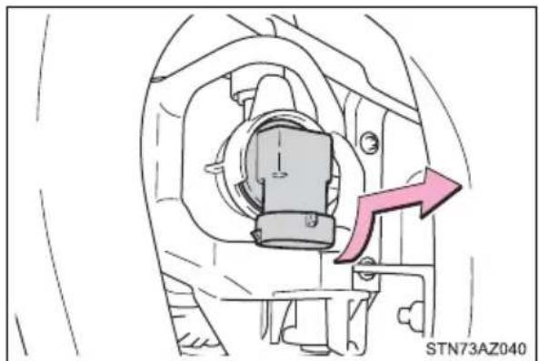
natural_image
Mechanical component diagram showing a piston and housing assembly with a pink arrow indicating direction (no text or symbols)4 Set the new light bulb.
Align the 3 tabs on the light bulb with the mounting, and insert. Turn it clockwise to set.
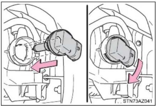
5 Install the connector.
Shake the bulb base gently to check that it is not loose, turn the fog lights, on once and visually confirm that no light is leaking through the mounting.
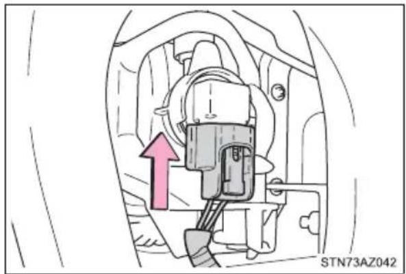
natural_image
Mechanical component diagram showing a highlighted assembly with an arrow and label (no readable text or symbols)6 Reinstall the fender liner and install the screws and clip.
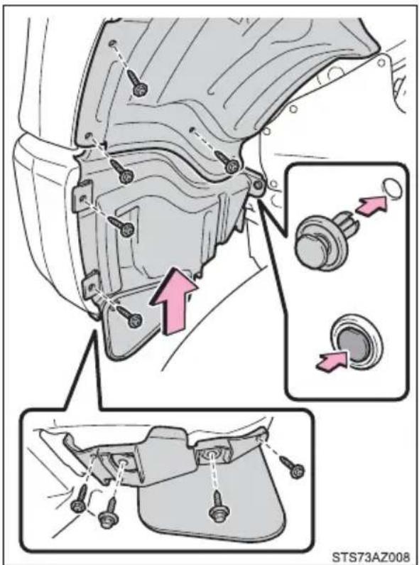
■Stop/tail and rear side marker lights, back-up lights and rear turn signal lights
1 Remove the bolts and rear combination assembly.
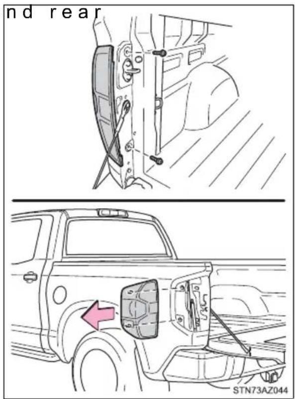
2 Turn the bulb bases counterclockwise.
① Rear turn signal light
② Back-up light
③ Stop/tail and rear side marker light
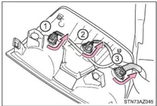
3 Remove the light bulb.
① Rear turn signal light
② Back-up light
③ Stop/tail and rear side marker light
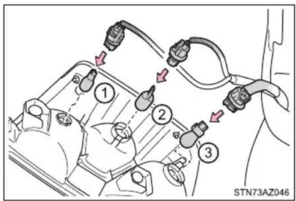
■License plate lights
1 Turn the bulb base counterclockwise.
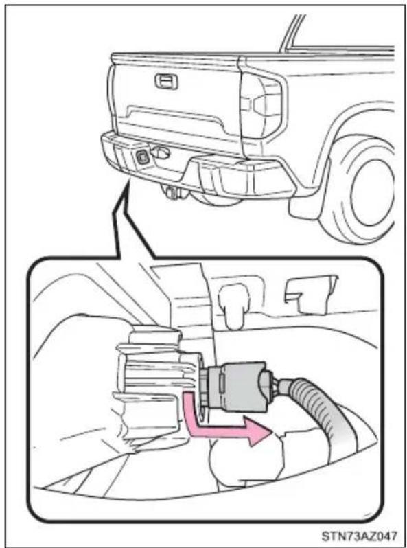
2 Remove the light bulb.
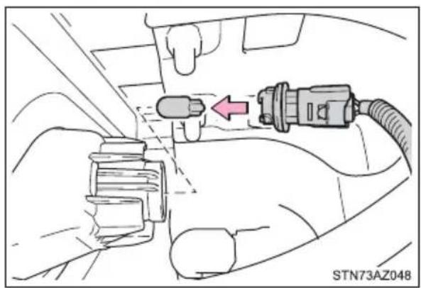
natural_image
Diagram of a car's seatbelt connector with a red arrow indicating left side (no text or symbols present)■High mounted stoplight and cargo lamps
1 Remove the cover.
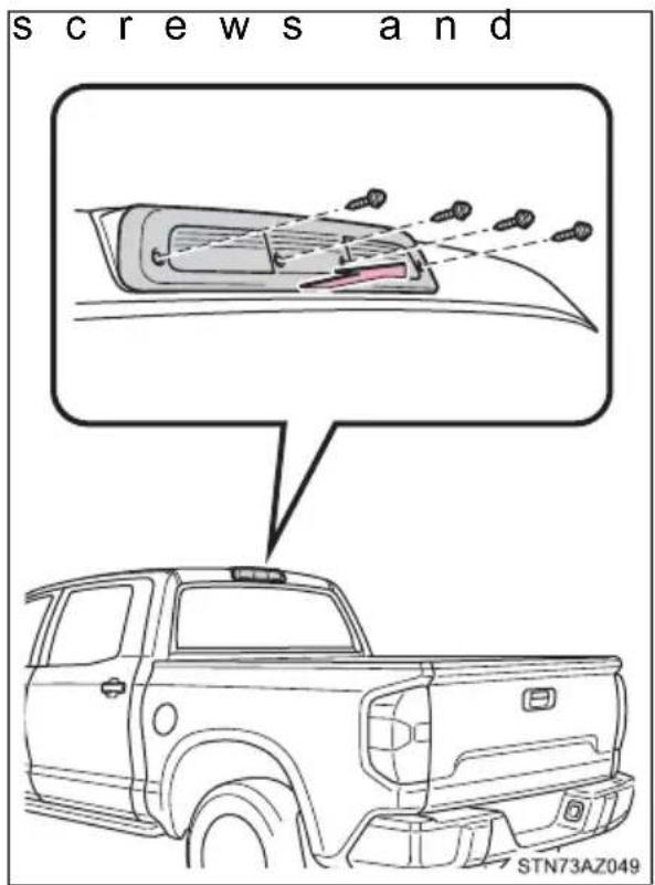
2 Remove the light bulb.
① High mounted stoplight
② Cargo lamps
When reinstalling the outer lens, confirm that the packing is properly seated in the groove on the housing.
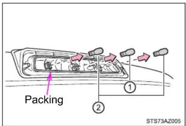
■ Replacing the following bulbs
If any of the lights listed below has burnt out, have it replaced by your Toyota dealer.
●Daytime running lights/parking lights (LED type)
●Side turn signal lights (if equipped)
●Outer foot lights (if equipped)
■When installing the rubber cover of the headlight
Ensure the rubber cover is securely attached.
① Fit the rubber cover outer circumference in firmly.
② Fit the rubber cover around the light bulb in until the light bulb plug can be seen.
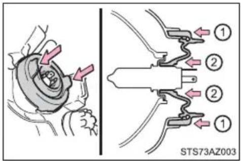
■When replacing the light bulbs
Confirm that they are properly engaged with the bulb base and that there is no light leakage.
LED Lights
The headlights (LED type), front fog lights (LED type), parking lights (LED type), daytime running light and side turn signal lights consist of a number of LEDs. If any of the LEDs burn out, take your vehicle to your Toyota dealer to have the light replaced.
■Condensation build-up on the inside of the lens
Temporary condensation build-up on the inside of the headlight lens does not indicate a malfunction. Contact your Toyota dealer for more information in the following situations:
●Large drops of water have built up on the inside of the lens.
●Water has built up inside the headlight.

WARNING
■Replacing light bulbs
- Turn off the lights. Do not attempt to replace the bulb immediately after turning off the lights.
The bulbs become very hot and may cause burns.
- Do not touch the glass portion of the light bulb with bare hands. When it is unavoidable to hold the glass portion, use and hold with a clean dry cloth to avoid getting moisture and oils on the bulb.
Also, if the bulb is scratched or dropped, it may blow out or crack.
● Fully install light bulbs and any parts used to secure them. Failure to do so may result in heat damage, fire, or water entering the headlight unit. This may damage the lights or cause condensation to build up on the lens.
- Do not attempt to repair or disassemble the bulb, bulb base, electrical wiring, or subcomponents.
Doing so could result in electric shock and serious injury.
■To prevent damage or fire
● Make sure bulbs are fully seated and locked.
- Check the wattage of the bulb before installing to prevent heat damage.
When trouble arises
7-1. Essential information
Emergency flashers ..... 474
If your vehicle has to be stopped in an emergency 475
If the vehicle is trapped in rising water.... 477
7
7-2. Steps to take in an emergency
If your vehicle needs to be towed 478
If you think something is wrong 483
Fuel pump shut off system 484
If a warning light turns on or a warning buzzer sounds .... 485
If a warning message is displayed.... 493
If you have a flat tire...... 506
If the engine will not start.... 521
If the electronic key does not operate properly (vehicles with a smart key system).... 523
If the vehicle battery is discharged .... 525
If your vehicle overheats ... 529
If the vehicle becomes stuck .... 532
Emergency flashers
The emergency flashers are used to warn other drivers when the vehicle has to be stopped in the road due to a breakdown, etc.
Press the switch.
All the turn signal lights will flash. To turn them off, press the switch once again.
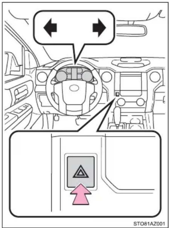
Emergency flashers
If the emergency flashers are used for a long time while the engine is not operating, the battery may discharge.
If your vehicle has to be stopped in an emergency
Only in an emergency, such as if it becomes impossible to stop the vehicle in the normal way, stop the vehicle using the following procedure:
1 Steadily step on the brake pedal with both feet and firmly depress it. Do not pump the brake pedal repeatedly as this will increase the effort required to slow the vehicle.
2 Shift the shift lever to N.
If the shift lever is shifted to N
3 After slowing down, stop the vehicle in a safe place by the road.
4 Stop the engine.
If the shift lever cannot be shifted to N
3 Keep depressing the brake pedal with both feet to reduce vehicle speed as much as possible.
4 Vehicles without a smart key system: Stop the engine by turning the engine switch to ACC.
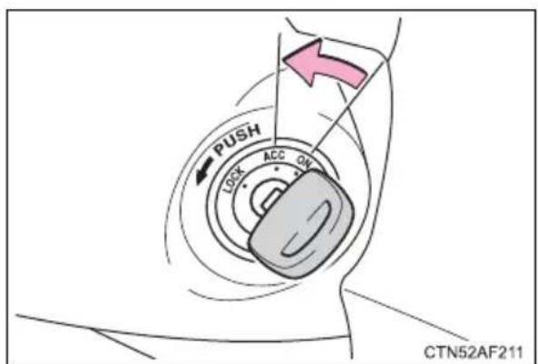
4 Vehicles with a smart key system: To stop the engine, press and hold the engine switch for 2 consecutive seconds or more, or press it briefly 3 more in succession.
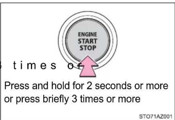
5 Stop the vehicle in a safe place by the road.

WARNING
If the engine has to be turned off while driving
● Power assist for the brakes and steering wheel will be lost, making the brake pedal harder to depress and the steering wheel heavier to turn. Decelerate as much as possible before turning off the engine.
● Vehicles without a smart key system: Never attempt to remove the key, as doing so will lock the steering wheel.
If the vehicle is trapped in rising water
In the event the vehicle is submerged in water, remain calm and perform the following.
- Remove the seat belt first.
- If the door can be opened, open the door and exit the vehicle.
- If the door can not be opened, open the window using the power window switch and exit the vehicle through the window.
- If the window can not be opened using the power window switch, remain calm, wait until the water level inside the vehicle rises to the point that the water pressure inside of the vehicle equals the water pressure outside of the vehicle, and then open the door and exit the vehicle.

WARNING
■ Using an emergency hammer\* for emergency escape
The front side windows and rear side windows, as well as the rear window can be shattered with an emergency hammer* used for emergency escape. However, an emergency hammer can not shatter the windshield as it is laminated glass.
*: Contact your Toyota dealer or aftermarket accessory manufacturer for further information about an emergency hammer.
■Escaping the vehicle from the window
There are cases where escaping the vehicle from the window is not possible due to seating position, passenger body type, etc.
When using an emergency hammer, consider your seat location and the size of the window opening to ensure that the opening is accessible and large enough to escape.
If your vehicle needs to be towed
If towing is necessary, we recommend having your vehicle towed by your Toyota dealer or commercial towing service, using a wheel-lift type truck or flatbed truck.
Use a safety chain system for all towing, and abide by all state/provincial and local laws.
If towing your vehicle with a wheel-lift type truck from the front, the vehicle's rear wheels and axles must be in good conditions.
(→P. 478, 480)
If they are damaged, use a towing dolly or flatbed truck.

WARNING
Observe the following precautions.
Failure to do so may result in death or serious injury.
■When towing the vehicle
2WD models: Be sure to transport the vehicle with all four wheels raised off the ground. If the vehicle is towed with the tires contacting the ground, the drivetrain and related parts may be damaged or an accident may occur due to a change in direction of the vehicle.
4WD models: Be sure to transport the vehicle with all four wheels raised off the ground. If the vehicle is towed with the tires contacting the ground, the drivetrain or related parts may be damaged, the vehicle may fly off the truck.
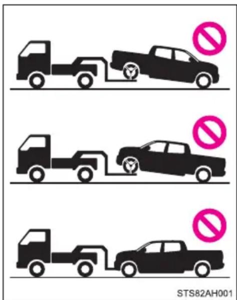

WARNING
■While towing
- When towing using cables or chains, avoid sudden starts, etc. which place excessive stress on the towing eyelets, cables or chains. The towing eyelets, cables or chains may become damaged, broken debris may hit people, and cause serious damage.
●Do not turn the engine switch to OFF.
There is a possibility that the steering wheel is locked and cannot be operated.

NOTICE
■ To prevent damage to the vehicle when towing using a wheel-lift type truck
● Vehicles without a smart key system:
Do not tow the vehicle from the rear when the engine switch is in OFF or the key is removed.
The steering lock mechanism is not strong enough to hold the front wheels straight.
● Vehicles with a smart key system:
Do not tow the vehicle from the rear when the engine switch is off.
The steering lock mechanism is not strong enough to hold the front wheels straight.
- When raising the vehicle, ensure adequate ground clearance for towing at the opposite end of the raised vehicle. Without adequate clearance, the vehicle could be damaged while being towed.
To prevent damage to the vehicle when towing with a sling-type truck
Do not tow with a sling-type truck, either from the front or rear.
■To prevent damage to the vehicle during emergency towing
Do not secure cables or chains to the suspension components.
Situations when it is necessary to contact dealers before towing
The following may indicate a problem with your transmission. Contact your Toyota dealer or commercial towing service before towing.
●The engine is running but the vehicle does not move.
●The vehicle makes an abnormal sound.
Towing with a wheel-lift type truck
From the front
Use a towing dolly under the rear wheels. Release the parking brake.
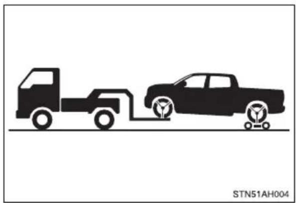
natural_image
Silhouette illustration of a pickup truck and a pickup truck with fuel pumps, no text or symbols presentFrom the rear
Use a towing dolly under the front wheels.
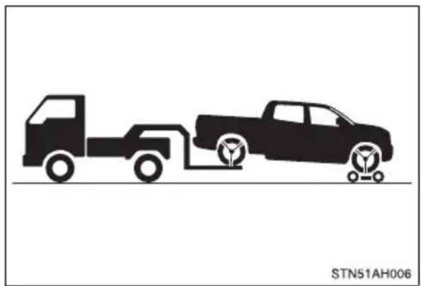
natural_image
Silhouette illustration of two pickup trucks with fuel pumps, no text or symbols present
NOTICE
■Towing with a sling-type truck
Do not tow with a sling-type truck to prevent body damage.
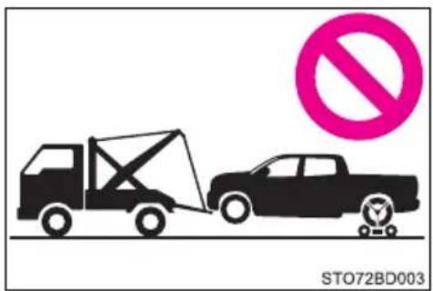
Using a flatbed truck
When using a flat-bed truck to transport the vehicle, use tire strapping belts. Refer to the owner's manual of the flat-bed truck for the tire strapping method.
In order to suppress vehicle movement during transportation, set the parking brake and turn the engine switch to OFF.
Emergency towing
If a tow truck is not available in an emergency, your vehicle may be temporarily towed using cables or chains secured to the emergency towing hooks. This should only be attempted on hard surfaced roads for at most 50 miles (80 km) at under 18 mph (30km/h).
A driver must be in the vehicle to steer and operate the brakes. The vehicle's wheels, drive train, axles, steering and brakes must be in good condition.
Emergency towing procedure
1 Securely attach cables or chains to the towing hooks. Take care not to damage the vehicle body.
▶ Type A ▶ Type B
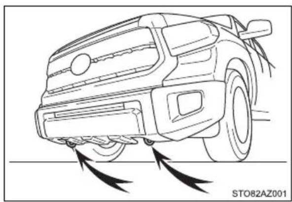
natural_image
Line drawing of a car head with motion arrows indicating vehicle flow or damage (no text or symbols)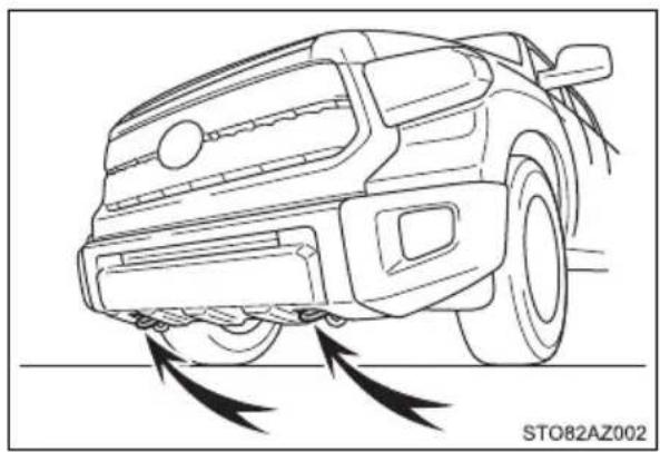
natural_image
Line drawing of a car's front wheel with motion arrows indicating tire movement (no text or symbols)2 Enter the vehicle being towed and start the engine. If the engine does not start, turn the engine switch to ON.
3 4WD models: Put the front-wheel drive control switch in "2WD".
4 Shift the shift lever to N and release the parking brake. When the shift lever cannot be shifted. (→P. 229)
While towing
If the engine is not running, the power assist for the brakes and steering will not function, marking steering and braking more difficult.
If you think something is wrong
If you notice any of the following symptoms, your vehicle probably needs adjustment or repair. Contact your Toyota dealer as soon as possible.
Visible symptoms
●Fluid leaks under the vehicle.
(Water dripping from the air conditioning after use is normal.)
●Flat-looking tires or uneven tire wear
●Engine coolant temperature gauge needle continually points higher than normal.
●Voltmeter continually points higher or lower than normal
●Engine oil pressure gauge continually points lower than normal
●Automatic transmission fluid temperature warning message is displayed
Audible symptoms
●Changes in exhaust sound
●Excessive tire squeal when cornering
●Strange noises related to the suspension system
●Pinging or other noises related to the engine
Operational symptoms
●Engine misses, stumbling or running roughly
●Appreciable loss of power
●Vehicle pulls heavily to one side when braking
●Vehicle pulls heavily to one side when driving on a level road
● Loss of brake effectiveness, spongy feeling, pedal almost touches the floor
Fuel pump shut off system
To minimize the risk of fuel leakage when the engine st when an airbag inflates upon collision, the fuel pump shut off system stops supply of fuel to the engine.
Follow the procedure below to restart the engine after the system is activated.
1 Turn the engine switch to ACC or OFF.
2 Restart the engine.

NOTICE
■Before starting the engine
Inspect the ground under the vehicle.
If you find that fuel has leaked onto the ground, the fuel system has been damaged and is in need of repair. Do not restart the engine.
If a warning light turns on or a warning buzzer sounds
Calmly perform the following actions if any of the warning lights comes on or flashes. If a light comes on or flashes, but then goes off, this does not necessarily indicate a malfunction in the system. However, if this continues to occur, have the vehicle inspected by your Toyota dealer.
Warning light and warning buzzer list
| Warning light | Warning light/Details/Actions |
 (U.S.A.) (U.S.A.) (Canada) (Canada) | Brake system warning light (warning buzzer)Low brake fluidMalfunction in the brake system→Immediately stop the vehicle in a safe place and contact your Toyota dealer. |
 | Charging system warning lightIndicates a malfunction in the vehicle's charging system→Immediately stop the vehicle in a safe place and contact your Toyota dealer. |
 (U.S.A.) (U.S.A.) (Canada) (Canada) | Malfunction indicator lampIndicates a malfunction in:The electronic engine control system;The electronic throttle control system; orThe electronic automatic transmission control system.→Have the vehicle inspected by your Toyota dealer immediately. |
 | SRS warning lightIndicates a malfunction in:The SRS airbag system;The front passenger occupant classification system; orThe seat belt pretensioner system→Have the vehicle inspected by your Toyota dealer immediately. |
 (U.S.A.) (U.S.A.) (Canada) (Canada) | ABS warning lightIndicates a malfunction in:The ABS; orThe brake assist system→Have the vehicle inspected by your Toyota dealer immediately. |
 | Low fuel level warning lightStandard fuel tankIndicates remaining fuel is approximately 4.0 gal. (15.0 L, 3.3 Imp.gal.) or lessLarge fuel tankIndicates remaining fuel is approximately 3.8 gal. (14.4 L, 3.2 Imp.gal.) or less→Refuel the vehicle. |
 | Seat belt reminder light (warning buzzer)*1Warns the driver and/or front passenger to fasten their seat belts→Fasten the seat belt.If the front passenger's seat is occupied, the front passenger's seat belt also needs to be fastened to make the warning light (warning buzzer) turn off. |
 | Master warning lightA buzzer sounds and the warning light comes on and flashes to indicate that the master warning system has detected a malfunction.→P. 493 |
 (U.S.A.) (U.S.A.) (Canada) (Canada) | Parking brake warning light (warning buzzer)*2Indicates that the parking brake is engaged.→Release the parking brake.Tire pressure warning light |
| When the light comes on:Low tire inflation pressure such asNatural causes ( P. 490)Flat tire ( P. 506) Adjust the tire inflation pressure to the specified level.The light will turn off after a few minutes. In cas the light does not turn off even if the tire inflation pressure is adjusted, have the system checked by your Toyota dealer. | |
| When the light comes on after blinking for 1 minute:Malfunction in the tire pressure warning system. Have the system checked by your Toyota dealer. | |
 | Slip indicatorIndicates a malfunction in:The VSC system;Trailer Sway Control system;The TRAC system;The hill-start assist control system; orThe AUTO LSD system. Have the vehicle inspected by your Toyota dealer immediately.The light will flash when any of the above systems other than the hill-start assist control are operating. |
 | PCS warning light (If equipped)When a buzzer sounds simultaneously:Indicates a malfunction has occurred in the PCS (Pre-Collision System).→Have the vehicle inspected by your Toyota dealer immediately.When a buzzer does not sound:The PCS (Pre-Collision System) has become temporarily unavailable, corrective action may be necessary.→Follow the instructions displayed on the multi-information display. (→P. 258, 493)If the PCS (Pre-Collision System) or VSC (Vehicle Stability Control) system is disabled, the PCS warning light will illu-minate.→P. 271 |
 (Yellow) (Yellow) | LDA (Lane Departure Alert) indicator (If equipped)The indicator comes on and a warning message is dis-played to indicate that the LDA (Lane Departure Alert) system is not available temporarily or has detected a mal-function.→P. 493 |
*1: Driver's seat belt buzzer:
The driver's seat belt warning buzzer sounds to alert the driver that his or her seat belt is not fastened. Once the engine switch is turned to the "ON" position (vehicles without smart entry & start system) or IGNITION ON mode (vehicles with smart entry & start system), the buzzer sounds. If the seat belt is still unfastened, the buzzer sounds intermittently for a certain period of time after the vehicle reaches a certain speed.
Front passenger's seat belt buzzer:
The front passenger's seat belt warning buzzer sounds to alert the front passenger that his or her seat belt is not fastened. If the seat belt is unfastened, the buzzer sounds intermittently for a certain period of time after the vehicle reaches a certain speed.
*2: Parking brake engaged warning buzzer:
A buzzer will sound if the vehicle is driven at a speed of approximately 3 mph (5 km/h) or more.
■SRS warning light
This warning light system monitors the airbag sensor assembly, front impact sensors, side impact sensors (front door), side impact sensors (rear), driver's seat position sensor, driver's seat belt buckle switch, front passenger occupant classification system (ECU and sensors), "AIR BAG ON" indicator light, "AIR BAG OFF" indicator light, front passenger's seat belt buckle switch, seat belt pretensioners assemblies, airbags, interconnecting wiring and power sources. (→P. 42)
■Front passenger detection sensor, seat belt reminder and warning buzzer
- If luggage is placed on the front passenger seat, the front passenger detection sensor may cause the warning light to flash and the warning buzzer to sound even if a passenger is not sitting in the seat.
- If a cushion is placed on the seat, the sensor may not detect a passenger, and the warning light may not operate properly.
If the malfunction indicator lamp comes on while driving
First check the following:
●Is the fuel tank empty?
If it is, fill the fuel tank immediately.
●Is the fuel tank cap loose?
If it is, tighten it securely.
The light will go off after several driving trips.
If the light does not go off even after several trips, contact your Toyota dealer as soon as possible.
■When the tire pressure warning light comes on
Check the tire inflation pressure and adjust to the appropriate level. Pushing the tire pressure warning reset switch will not turn off the tire pressure warning light.
■The tire pressure warning light may come on due to natural causes
The tire pressure warning light may come on due to natural causes such as natural air leaks and tire inflation pressure changes caused by temperature. In this case, adjusting the tire inflation pressure will turn off the warning light (after several minutes).
■When a tire is replaced with a spare tire
The temporary spare tire is not equipped with a tire pressure warning valve and transmitter. If a tire goes flat, the tire pressure warning light will not turn off even though the flat tire has been replaced with the temporary spare tire. Replace the temporary spare tire with the repaired tire and adjust the tire inflation pressure. The tire pressure warning light will go off after several minutes.
■ Conditions that the tire pressure warning system may not function properly
→P. 432
If the tire pressure warning light frequently comes on after blinking for 1 minute
If the tire pressure warning light frequently comes on after blinking for 1 minute when the engine switch is turned to ON, have it checked by your Toyota dealer.
Warning buzzer
In some cases, the buzzer may not be heard because of noisy place or an audio sound.

WARNING
If both the ABS and the brake system warning lights remain on
Stop your vehicle in a safe place immediately and contact your Toyota dealer. The vehicle will become extremely unstable during braking, and the ABS system may fail, which could cause an accident resulting in death or serious injury.
If the tire pressure warning light comes on
Be sure to observe the following precautions. Failure to do so could cause a loss of vehicle control and result in death or serious injury.
- Stop your vehicle in a safe place as soon as possible. Adjust the tire inflation pressure immediately.
- If the tire pressure warning light comes on even after tire inflation pressure adjustment, it is probable that you have a flat tire. Check the tires. If a tire is flat, change it with the spare tire and have the flat tire repaired by the nearest Toyota dealer.
● Avoid abrupt maneuvering and braking. If the vehicle tires deteriorate, you could lose control of the steering wheel or the brakes.
If a blowout or sudden air leakage should occur
The tire pressure warning system may not activate immediately.
■ Maintenance of the tires
Each tire, including the spare (if provided), should be checked monthly when cold and inflated to the inflation pressure recommended by the vehicle manufacturer on the vehicle placard or tire inflation pressure label (tire and load information label). (If your vehicle has tires of a different size than the size indicated on the vehicle placard or tire inflation pressure label [tire and load information label], you should determine the proper tire inflation pressure for those tires.)
As an added safety feature, your vehicle has been equipped with a tire pressure monitoring system (TPMS-tire pressure warning system) that illuminates a low tire pressure telltale (tire pressure warning light) when one or more of your tires is significantly under-inflated. Accordingly, when the low tire pressure telltale (tire pressure warning light) illuminates, you should stop and check your tires as soon as possible, and inflate them to the proper pressure. Driving on a significantly under-inflated tire causes the tire to overheat and can lead to tire failure. Under-inflation also reduces fuel efficiency and tire tread life, and may affect the vehicle's handling and stopping ability.

WARNING
Please note that the TPMS (tire pressure warning system) is not a substitute for proper tire maintenance, and it is the driver's responsibility to maintain correct tire pressure, even if under-inflation has not reached the level to trigger illumination of the TPMS low tire pressure telltale (tire pressure warning light).
Your vehicle has also been equipped with a TPMS (tire pressure warning system) malfunction indicator to indicate when the system is not operating properly. The TPMS (tire pressure warning system) malfunction indicator is combined with the low tire pressure telltale (tire pressure warning light). When the system detects a malfunction, the telltale will flash for approximately one minute and then remain continuously illuminated. This sequence will continue upon subsequent vehicle start-ups as long as the malfunction exists. When the malfunction indicator is illuminated, the system may not be able to detect or signal low tire pressure as intended.
TPMS (tire pressure warning system) malfunctions may occur for a variety of reasons, including the installation of replacement or alternate tires or wheels on the vehicle that prevent the TPMS (tire pressure warning system) from functioning properly. Always check the TPMS (tire pressure warning system) malfunction telltale after replacing one or more tires or wheels on your vehicle to ensure that the replacement or alternate tires and wheels allow the TPMS (tire pressure warning system) to continue to function properly.

NOTICE
■To ensure the tire pressure warning system operates properly
Do not install tires with different specifications or makers, as the tire pressure warning system may not operate properly.
If a warning message is displayed
If a warning is shown on the multi-information display, stay calm and perform the following actions:
① Master warning light
The master warning light also comes on or flashes in order to indicate that a message is currently being displayed on the multi-information display.
② Multi-information display
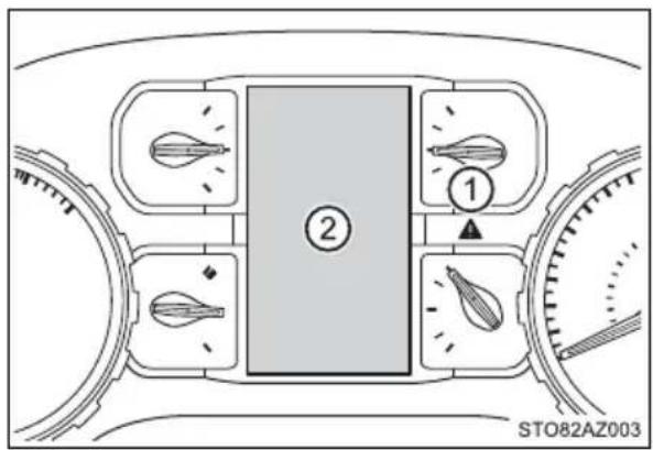
If any of the warning light comes on again after the following actions have been performed, contact your Toyota dealer.
Warning message and warning buzzer list
| Warning message Details/Actions | |
 (If equipped) (If equipped) | Indicates that:There is a high possibility of a frontal collision;orThe pre-collision braking function is operatingA buzzer also sounds.→ Slow the vehicle by applying the brakes. |
 (If equipped) (If equipped) | Indicates that your vehicle is nearing the vehicle ahead (in vehicle-to-vehicle distance control mode)A buzzer also sounds.→ Slow the vehicle by applying the brakes. |
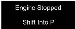  (Flashes) (Flashes) | Indicates that the engine was stopped with the shift lever not in P.A buzzer also sounds.→ Shift the shift lever to P. |
Engine StoppedStop In a Safe Place (Flashes) (Flashes) | Indicates that the engine was stopped while driving.A buzzer also sounds.→ Stop the vehicle in a safe place such as the shoulder of a road. |
Engine Coolant Temp HighStop in a Safe Place See Owner's Manual | Indicates that the engine coolant temperature is too highA buzzer also sounds.→ Immediately stop the vehicle in a safe place and contact your Toyota dealer. |
CHECK TRANSMISSION SYSTEM | Indicates a malfunction in the automatic transmission systemA buzzer also sounds.→ Have the vehicle inspected by your Toyota dealer immediately. |
Parking Assist Malfunction (If equipped) (If equipped) | Indicates a malfunction in the intuitive parking assistThe malfunctioning assist-sensor is flashing.→ Have the vehicle inspected by your Toyota dealer immediately. |
Y77Aoot Monitor functionour Dealer (If equipped) (If equipped) | Indicates a malfunction in the Blind Spot Monitor A buzzer also sounds.→ Have the vehicle inspected by your Toyota dealer immediately. |
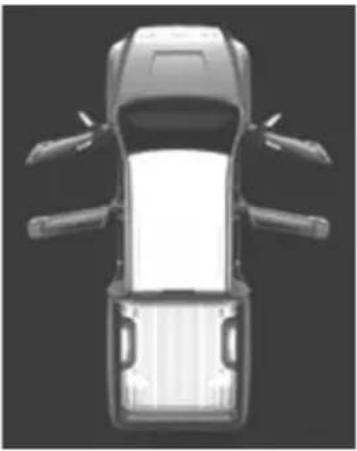 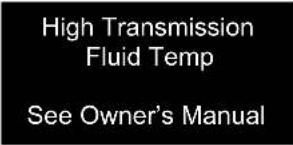 | Indicates that one or more of the doors or the hood is not fully closedThe system also indicates which doors are not fully closed.If the vehicle reaches a speed of 3 mph(5 km/h),flashes and a buzzer sounds to indicate that the door(s) are not yet fully closed.→ Make sure that all the doors and the hood are closed.Indicates that the automatic transmission fluid temperature is to highA buzzer also sounds.→ Immediately stop the vehicle in a safe place, shift the shift lever to P and wait until the light goes off.If the light goes off, you may start the vehicle again. If the light does not go off, contact your Toyota dealer. |
 | |
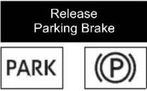 (U.S.A) (Canada) (U.S.A) (Canada) | Indicates that the parking brake is still engagedIf the vehicle reaches a speed of 3 mph(5 km/h),flashes and a buzzersounds to indicate that the parking brake is still engaged.→ Release the parking brake. |
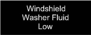 | Indicates that the washer fluid level is low→ Add washer fluid. |
 | |
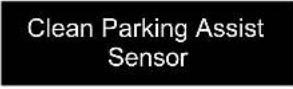 | Indicates that intuitive parking assist is dirty or covered with ice→ Clean the sensor. |
 (If equipped) (If equipped) | |
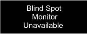 | Indicates that the Blind Spot Monitor sensors or the surrounding area on the bumper is dirty or covered with iceA buzzer also sounds.→ Clean the sensor and its surrounding area on the bumper. |
 (If equipped) (If equipped) | |
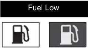 | ► Standard fuel tankIndicates remaining fuel is approximately 4.0 gal.(15.0 L, 3.3 Imp.gal.) or less► Large fuel tankIndicates remaining fuel is approximately 3.8 gal.(14.4 L, 3.2 Imp.gal.) or lessA buzzer also sounds.→ Refuel the vehicle. |
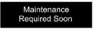 | Indicates that all maintenance according to the driven distance on the maintenance schedule* should be performed soon.Comes on approximately 4500 miles (7200 km) after the message has been reset.→If necessary, perform maintenance. |
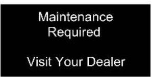 | Indicates that all maintenance is required to correspond to the driven distance on the maintenance schedule*.Comes on approximately 5000 miles (8000 km) after the message has been reset.(The indicator will not work properly unless the message has been reset.)→Perform the necessary maintenance.Please reset the message after the maintenance is performed. (→P. 407) |
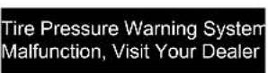 (Z72Z)(Flashes and then remains on) (Z72Z)(Flashes and then remains on) | Indicates a malfunction in the tire pressure warning system.The tire pressure warning light comes on after flashing for 1 minute.→Have the vehicle inspected by your Toyota dealer. |
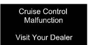 (YDY4) (YDY4) | Indicates a malfunction in the cruise control system.• Press the “ON-OFF” button once to deactivate the system, and then press the button again to reactivate the system.• A buzzer also sounds.→Have the vehicle inspected by your Toyota dealer immediately. |
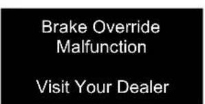 (2H85) (2H85) | Indicates a malfunction in the Brake Override System.A buzzer also sounds.→Have the vehicle inspected by your Toyota dealer immediately. |
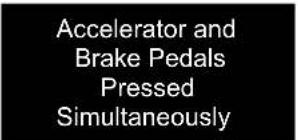 (6CW6) (6CW6) | Indicates that the accelerator and brake pedals are being depressed simultaneously, and the Brake Override System is operating. (→P. 185)→Release the accelerator pedal and depress the brake pedal. |
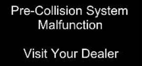  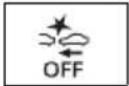 (If equipped) (If equipped) | Indicates a malfunction in the PCS (Pre-Collision System).A buzzer also sounds.→ Have the vehicle inspected by your Toyota dealer. |
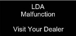   (Yellow)(If equipped) (Yellow)(If equipped) | Indicates a malfunction in the LDA (Lane Departure Alert).A buzzer also sounds.→ Have the vehicle inspected by your Toyota dealer. |
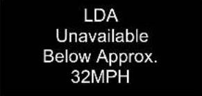 (If equipped) (If equipped) | Indicates that the LDA (Lane Departure Alert) system cannot be used as the vehicle speed is lower than approximately 32 mph (50 km/h).→ Drive the vehicle at approximately 32 mph (50 km/h) or more. |
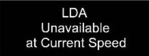 (If equipped) (If equipped) | Indicates that LDA (Lane Departure Alert) system cannot be used due to the vehicle speed being too high.→ Slow down. |
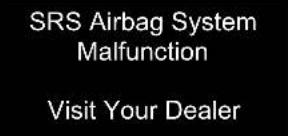  | Indicates a malfunction in the SRS airbag system.A buzzer also sounds.→ Have the vehicle inspected by your Toyota dealer. |
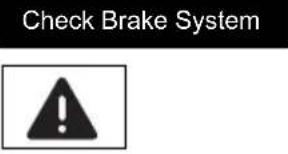 | Indicates the following:• The brake fluid level is low; or• The brake system is malfunctioning.A buzzer also sounds.→ Immediately stop the vehicle in a safe place and contact your Toyota dealer. |
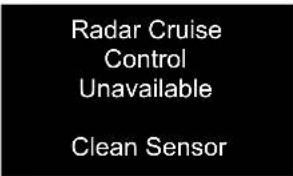  (If equipped) (If equipped) | Indicates that radar cruise control sensor is dirty or covered with ice. A buzzer also sounds. → Clean the sensor. |
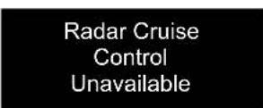  (If equipped) (If equipped) | Indicates that the dynamic radar cruise control system cannot be used temporarily due to bad weather A buzzer also sounds. → Use the dynamic radar cruise control system when it becomes available again. |
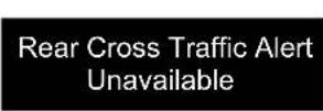  (If equipped) (If equipped) | Indicates that the RCTA (Rear Cross Traffic Alert) sensors or the surrounding area on the bumper is dirty or covered with ice (if equipped) A buzzer also sounds. → Clean the sensor and its surrounding area on the bumper. |
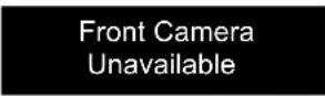  (Yellow) (If equipped) (Yellow) (If equipped) | The operation conditions of the front camera (temperature, etc.) are not met. → When the operation conditions of the front camera (temperature, etc.) are met, the following systems will become available. (→P. 258, 485) • PCS (Pre-Collision System) • LDA (Lane Departure Alert) system • Dynamic radar cruise control • Automatic High Beam |
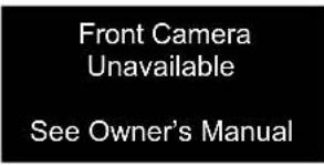   (Yellow) (If equipped) (Yellow) (If equipped) | Indicates that dirt, rain, condensation, ice, snow, etc., are present on the windshield in front of the front camera. The following systems may be suspended until the problem shown in the message is resolved. (→P. 258, 485) • PCS (Pre-Collision System) • LDA (Lane Departure Alert) system • Dynamic radar cruise control • Automatic High Beam → Tum the system off, remove any dirt, rain condensation, ice, snow, etc., from the windshield, and then turn the system back on. |
(If equipped)
| Warning message Details/Actions | |
   | Indicates a malfunction in the Drive-start control.A buzzer also sounds.→ Have the vehicle inspected by your Toyota dealer immediately. |
   | Indicates that the shift position was changed and Drive-Start Control was operated while depressing the accelerator pedal.→ Momentarily release the accelerator pedal. |
   | Indicates that the headlight switch is left on (with the key removed and the driver's door opened)A buzzer also sounds.→ Turn the lights off. |
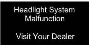  | Indicates a malfunction in:• The automatic headlight leveling system; or• The LED headlight system (if equipped).A buzzer also sounds.→ Have the vehicle inspected by your Toyota dealer. |
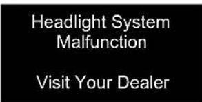   (If equipped) (If equipped) | Indicates a malfunction in the Automatic High Beam system.→ Have the vehicle inspected by your Toyota dealer. |
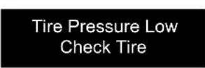  | Indicates that the tire inflation pressure is low.→ Check the tire inflation pressure, and adjust to the appropriate level. |
 (If equipped) (If equipped) | Indicates that the Automatic High Beam switch is pressed while the headlights are in low beam.→ Turn the high beam on and press the Automatic High Beam switch again. |
VSC Turned OffPre-Collision Brake SystemUnavailable  (If equipped) (If equipped) | Indicates that, since the VSC (Vehicle Stability Control) system was turned off, the pre-collision brake system operation is stopped.→Turn the VSC on. (→P. 323) |
Pre-Collision SystemUnavailable (If equipped) (If equipped) | Indicates that the pre-collision system is temporarily unavailable.→Please wait until the system returns. If the message does not disappear, the system may be malfunctioning. Have the vehicle inspected by your Toyota dealer immediately. |
Pre-Collision SystemUnavailableClean Sensor (If equipped) (If equipped) | Indicates that the pre-collision system sensor is dirty, covered with ice, etc.→Remove any dirt, ice, etc. |
Rear Cross Traffic AlertMalfunctionVisit Your Dealer | Indicates a malfunction in the RCTA (Rear Cross Traffic Alert).A buzzer also sounds.→Have the vehicle inspected by your Toyota dealer. |
Trailer Brake Error.If Towing, Come to a Safe Stop with Manual Controls.Contact dealer.K833]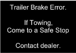  | Indicates that the VSC ECU or G sensor is not communicating with trailer brake control system. Indicates a malfunction in the VSC system.→Have the vehicle inspected by your Toyota dealer immediately.Indicates that an internal switch failure of trailer brake control system, an over current detected by trailer brake control system.→ Have the vehicle inspected by your Toyota dealer immediately.Indicates that an internal microprocessor error, output circuit to trailer brakes unintended current, or manual brake output slider is stuck or broken→ Have the vehicle inspected by your Toyota dealer immediately. |
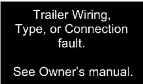  | Indicates that the output circuit has reverse voltage, or the internal trailer brake control system temperature is too high.→ Check trailer wiring issue, check trailer connection. If there is still a problem, have the vehicle inspected by your Toyota dealer immediately. |
*: Refer to the separate "Scheduled Maintenance Guide" or "Owner's Manual Supplement" for the maintenance interval applicable to your vehicle.
■Warning message in radar cruise mode (if equipped)
In the following cases, the warning message may not be displayed even if vehicle-to-vehicle distance decreases:
- When your vehicle and the vehicle ahead are traveling at the same speed or the vehicle ahead is traveling more quickly than your vehicle
- When the vehicle ahead is traveling at a very low speed
- Immediately after cruise control speed is set
●At the instant the accelerator pedal is depressed
■ Conditions that the tire pressure warning system may not function properly
→P. 432
Have the malfunction repaired immediately. (vehicles with a smart key system)
After taking the specified steps to correct the suspected problem, check that the warning message and light go off.
| Interior buzzer | Exterior buzzer | Warning message Details/Actions | ||
| Continuous | — | Shift into P Position (Flashes) (Flashes) | The driver's door was opened when the shift lever was not in P and the engine switch was not turned off.→ Shift the shift lever to P. | |
| Continuous | Continuous | Shift into P PositionKey Not Detected (Flashes) (Flashes) | The driver's door was opened and closed while the electronic key was not in the vehicle, the shift lever was not in P and the engine switch was not turned off.→ Shift the shift lever to P.→ Bring the electronic key back into the vehicle. | |
| Once 3 times | Key Not Detected (Flashes) (Flashes) | The driver's door was opened and closed while the electronic key was not in the vehicle, the shift lever was in P and the engine switch was not turned off.→ Turn the engine switch off.→ Bring the electronic key back into the vehicle. | ||
| The electronic key was carried outside the vehicle and a door other than the driver's door was opened and closed while the engine switch was in a mode other than off.→ Bring the electronic key back into the vehicle. | ||||
| Interior buzzer | Exterior buzzer | Warning message | Details/Actions | |
| Once | Continuous | Turn Power OFF  Key Not Detected Key Not Detected  (Flashes) (Flashes) | An attempt was made to exit the vehicle with the electronic key and lock the doors without first turning the engine switch off when the shift lever was in P.→Turn the engine switch off and lock the doors again. | |
| Once — | Key Not Detected  (Flashes) (Flashes) | The electronic key is not detected when an attempt is made to start the engine.→Start the engine with the electronic key present. | ||
| 9 times — | Key Not Detected  (Flashes) (Flashes) | An attempt was made to drive when the electronic key was not inside the vehicle.→Confirm that the electronic key is inside the vehicle. | ||
| — | Continuous | Key Detected in Vehicle  (Flashes) (Flashes) | An attempt was made to lock the doors using the smart key system while the electronic key was still inside the vehicle.→Retrieve the electronic key from the vehicle and lock the doors again. | |
| Once | Continuous | Key Detected in Vehicle  (Flashes) (Flashes) | An attempt was made to lock either front door by opening a door and putting the inside lock button into the lock position, then closing the door with the electronic key still inside the vehicle.→Retrieve the electronic key from the vehicle and lock the doors again. | |
| Once — | Key Battery Low  | The electronic key has a low battery.→Replace the electronic key battery. (→P. 451) | ||
| Interior buzzer | Exterior buzzer | Warning message | Details/Actions |
| Once — |   (Flashes) (Flashes) | The steering lock could not be released within 3 seconds of the engine switch being pressed.→Press the engine switch while depressing the brake pedal and moving the steering wheel left and right. | |
| Once — | 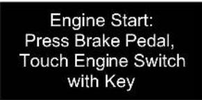  | ·When the doors were unlocked with the mechanical key and then the engine switch was pressed, the electronic key could not be detected in the vehicle.·The electronic key could not be detected in the vehicle even after the engine switch was pressed two consecutive times.→Touch the electronic key to the engine switch while depressing the brake pedal. | |
| Once — | 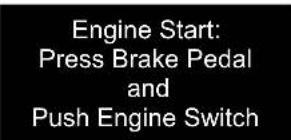  | Indicates that:·With the engine switch off, the doors were unlocked and then the driver's door was opened and closed·The engine switch was turned to ACC without starting the engine→Press the engine switch while depressing the brake pedal. | |
| Once — |   (Flashes) (Flashes) | The engine switch has been turned off with the shift lever in a position other than P.→Shift the shift lever to P. | |
| Interior buzzer | Exterior buzzer | Warning message Details/Actions | |
| Once — | 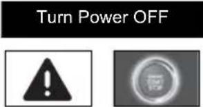 (Flashes) (Flashes) | After the engine switch has been turned off with the shift lever in a position other than P, the shift lever has been shifted to P.→Turn the engine switch off. | |
| Once — | 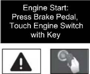  (Flashes) (Flashes) | During a engine starting procedure in the event that the electronic key was not functioning properly (→P. 523), the engine switch was touched with the electronic key.→Press the engine switch within 10 seconds of the buzzer sounding. | |
(Flashes)
Warning buzzer
→P. 490
If you have a flat tire
Your vehicle is equipped with a spare tire. The flat tire can be replaced with the spare tire.
For details about tires: →P. 426

WARNING
If you have a flat tire
Do not continue driving with a flat tire.
Driving even a short distance with a flat tire can damage the tire and the wheel beyond repair, which could result in an accident.
Before jacking up the vehicle
- Stop the vehicle in a safe place on a hard, flat surface.
●Set the parking brake.
●Shift the shift lever to P. - Stop the engine.
● Turn on the emergency flashers. (→P. 474)
Location of the spare tire, jack and tools
■Spare tire
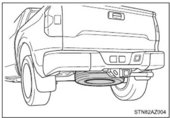
natural_image
Line drawing of a vehicle rear view showing tire, dashboard, and exhaust components (no text or symbols)Jack and tools
① Jack
② Tool bag
▶ Double Cab models without storage box
▶ Double Cab models with storage box

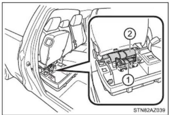
▶ CrewMax models
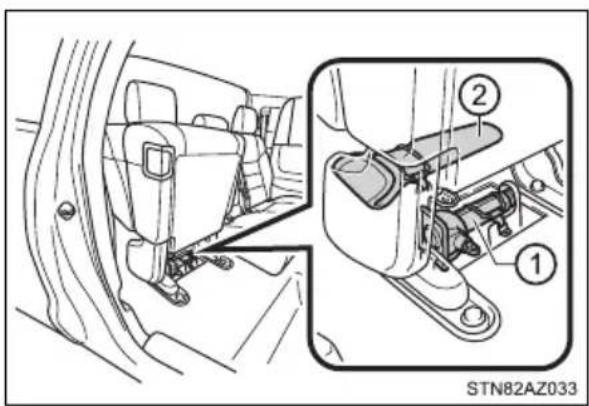

WARNING
■Using the tire jack
Observe the following precautions.
Improper use of the tire jack may cause the vehicle to suddenly fall off the jack, leading to death or serious injury.
- Do not use the tire jack for any purpose other than replacing tires or installing and removing tire chains.
- Only use the tire jack that comes with this vehicle for replacing a flat tire.
Do not use it on other vehicles, and do not use other tire replacing tires on this vehicle.
●Put the jack properly in its jack point. - Do not put any part of your body under the vehicle while it is supported by the jack.
- Do not start the engine or drive the vehicle while the vehicle is supported by the jack.
- Do not raise the vehicle while someone is inside.
- When raising the vehicle, do not put an object on or under the jack.
- Do not raise the vehicle to a height greater than that required to replace the tire.
- Use a jack stand if it is necessary to get under the vehicle.
- When lowering the vehicle, make sure that there is no-one near the vehicle. If there are people nearby, warn them vocally before lowering.
■Using the jack handle
Insert the square head securely until you hear a click to prevent the extension parts from coming apart unexpectedly.
Taking out the jack and tool bag (Double Cab models)
1 Pull up the lever and raise the bottom cushion up.
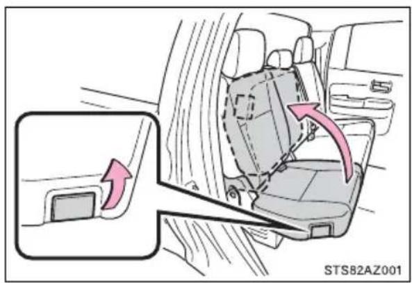
2 On vehicles with storage box, turn the knob to the "OPEN" direction and remove the lid.
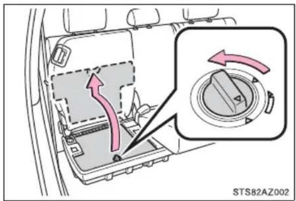
3 On vehicles with storage box, remove the jack cover panel.
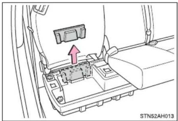
natural_image
Interior view of a car's internal battery compartment with a red arrow pointing to the component (no text or symbols visible)4 Unhook the rubber band and take out the jack.
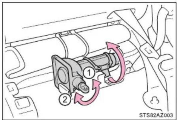
① For loosening
② For tightening
5 Unhook the rubber band and remove the tool bag.
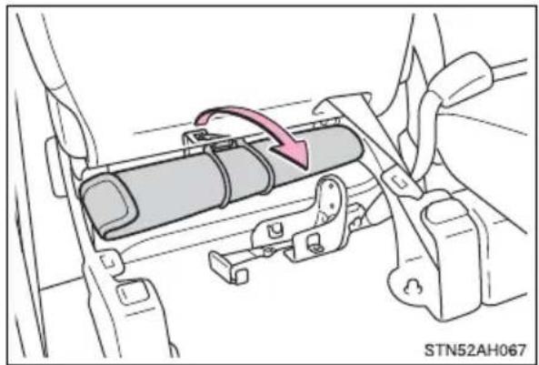
natural_image
Mechanical assembly diagram showing a lever mechanism with a red arrow indicating motion (no text or symbols present)Taking out the jack and tool bag (CrewMax models)
1 Pull the lever and raise the bottom cushion up.
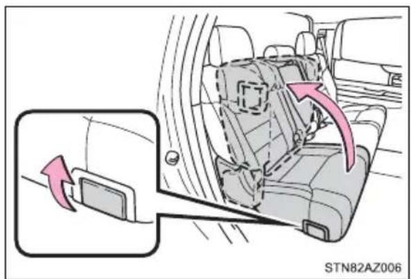
2 Unhook the rubber band and take out the jack.
① For loosening
② For tightening
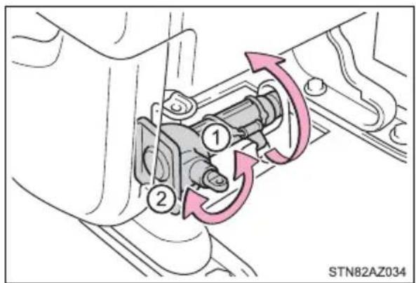
3 Unhook the rubber band and remove the tool bag.
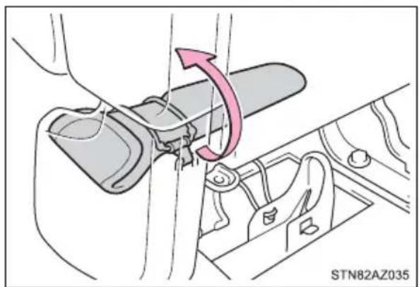
natural_image
Mechanical assembly diagram showing a lever mechanism with a pink arrow indicating rotation (no text or symbols present)Taking out the spare tire
1 Assemble the jack handle extension as shown.
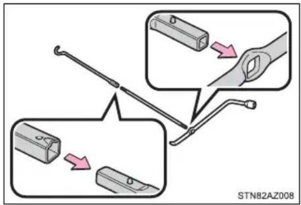
2 Insert the end of the jack handle extension into the lowering screw and turn it counterclockwise.
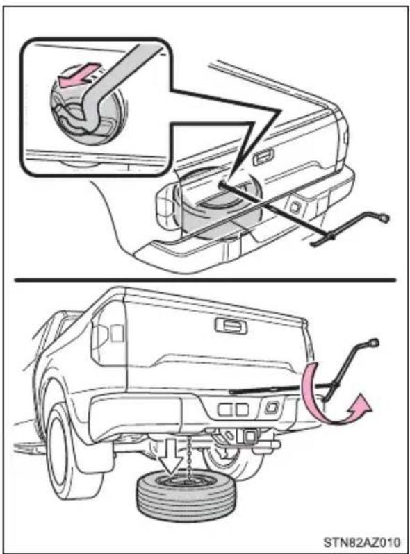
3 After the tire is lowered completely to the ground, remove the holding bracket.
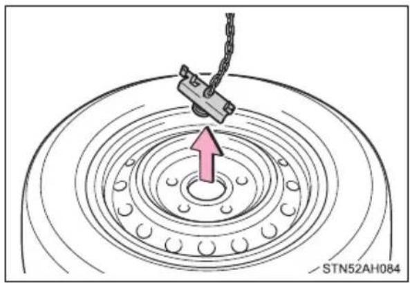
natural_image
Diagram of a mechanical clamp interacting with a circular bearing, showing concentric rings and a central hub (no text or symbols)Replacing a flat tire
1 Chock the tires.
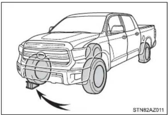
natural_image
Line drawing of a pickup truck with a head-mounted sensor or sensor, shown in perspective view (no text or symbols on the vehicle itself)| Flat tire Wheel chock positions | |
| Front | Left-hand side Behind the rear right-hand side tire |
| Right-hand side Behind the rear left-hand side tire | |
| Rear | Left-hand side In front of the front right-hand side tire |
| Right-hand side In front of the front left-hand side tire | |
2 On some models, remove the wheel ornament using the wheel nut wrench as shown.
To protect the wheel and wheel ornament, place a rag between the wrench and the wheel ornament, as shown in the illustration.
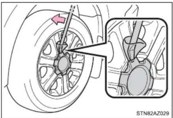
natural_image
Mechanical assembly diagram showing a wheel and gear assembly with a magnified inset (no text or symbols)3 Slightly loosen the wheel nuts (one turn).
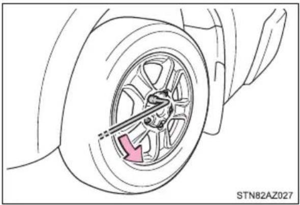
natural_image
Diagram of a car wheel with a highlighted brake component and a pink arrow indicating direction (no text or symbols)4 Assemble the jack handle extension as shown.
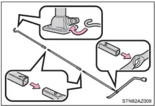
flowchart
graph TD
    A["Switch"] --> B["Close-up"]
    B --> C["Switch"]
    C --> D["Disassembly"]
    D --> E["Close-up"]
    E --> F["Switch"]
    style A fill:#f9f,stroke:#333
    style B fill:#ccf,stroke:#333
    style C fill:#cfc,stroke:#333
    style D fill:#fcc,stroke:#333
    style E fill:#cff,stroke:#333
    style F fill:#ffc,stroke:#333
5 Position the jack at the co jack point as shown.
① Front
② Rear
Make sure the jack is positioned on a level and solid place.
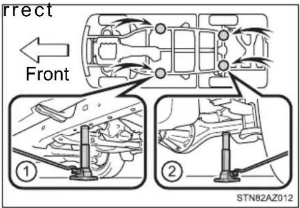
6 Raise the vehicle until the tire is slightly raised off the ground.
When positioning the jack under the rear axle housing, make sure the groove on the top of the jack fits with the rear axle housing.
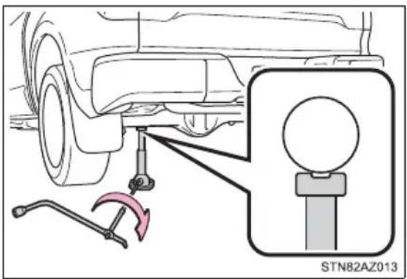
7 Remove all the wheel nuts and the tire.
When resting the tire on the ground, place the tire so that the wheel design faces up to avoid scratching the wheel surface.
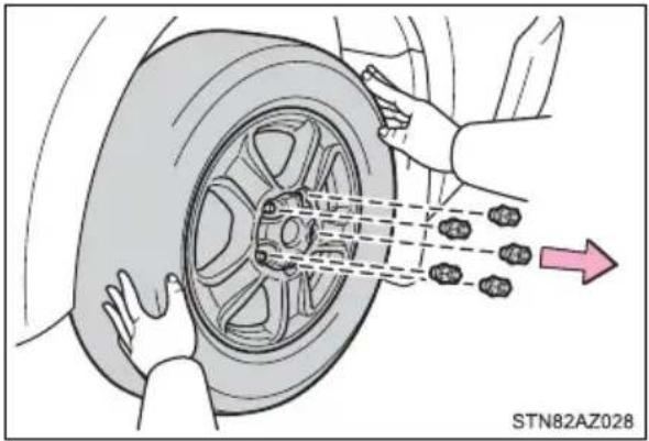

WARNING
■Replacing a flat tire
- Observe the following precautions.
Failure to do so may result in serious injury:
- Lower the spare tire completely to the ground before removing it from under the vehicle.
- Do not try to remove the wheel ornament by hand. Take due care in handling the ornament to avoid unexpected personal injury.
- Do not touch the disc wheels or the area around the brakes immediately after the vehicle has been driven.
After the vehicle has been driven the disc wheels and the area around the brakes will be extremely hot. Touching these areas with hands, feet or other body parts while changing a tire, etc., may result in burns.
● Failure to follow these precautions could cause the wheel nuts to loosen and the tire to fall off, resulting in death or serious injury.
- Have the wheel nuts tightened with a torque wrench as soon as possible after changing wheels.
Steel wheel: 154 ft·lbf (209 N·m, 21.3 kgf·m)
Aluminum wheel: 97 ft·lbf (131 N·m, 13.4 kgf·m)
- When installing a tire, only use wheel nuts that have been specifically designed for that wheel.
- Retighten the wheel nuts within 100 miles (160 km) of driving.
- If there are any cracks or deformations in the bolt screws, nut threads or bolt holes of the wheel, have the vehicle inspected by your Toyota dealer.
- Do not attach a heavily damaged wheel ornament, as it may fly off the wheel while the vehicle is moving.
- When installing the wheel nuts, be sure to install them with the tapered ends facing inward.
Installing the spare tire
1 Remove any dirt or foreign matter from the wheel contact surface.
If foreign matter is on the wheel contact surface, the wheel nuts may loosen while the vehicle is in motion, causing the tire to come off.
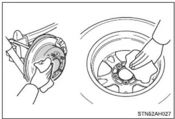
natural_image
Technical illustration showing two mechanical components: a wheel assembly and a wheel rim with hands (no text or symbols)2 Install the spare tire and loosely tighten each wheel nut by hand by approximately the same amount.
Tighten the nuts until the tapered portion comes into loose contact with the disc wheel seat.
- Replacing a steel wheel with a steel wheel
Replacing an aluminum wheel with a steel wheel
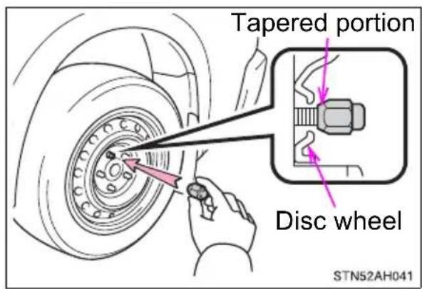
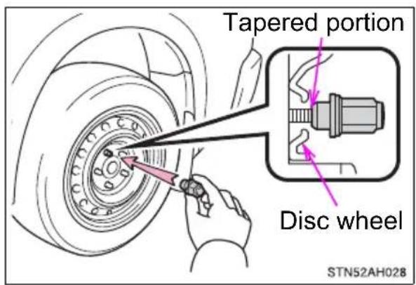
3 Lower the vehicle.
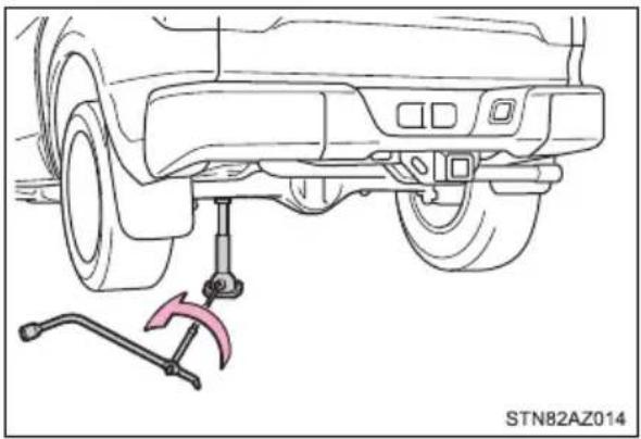
natural_image
Technical line drawing of a car undercarriage with a wrench and clamp attachment (no text or symbols)4 Firmly tighten each nut two or three times in the order shown in the illustration.
Tightening torque: 154 ft·lbf (209 N·m, 21.3 kgf·m)
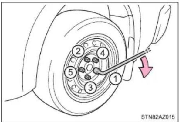

WARNING
■ Stowing the flat tire
Failure to follow steps listed under stowing the tire may result in damage to the spare tire carrier and loss of the tire, which could result in serious injury or death.
Stowing the flat tire, jack and all tools
1 Vehicles with aluminum wheels: Remove the center wheel ornament by pushing from the reverse side.
2 Lay down the tire with the valve stem facing up and install the holding bracket, inserting the claw into the wheel lug nut hole. Turn the jack handle extension clockwise to take up slack in the chain.
Then, check to ensure the claw is in the wheel lug nut hole and the holding bracket is centered in the wheel hub.
① Holding bracket
② Claw
While raising, secure the tire, taking care that the tire goes straight up without catching on any surrounding part, to prevent it from flying forward during a collision or sudden braking.
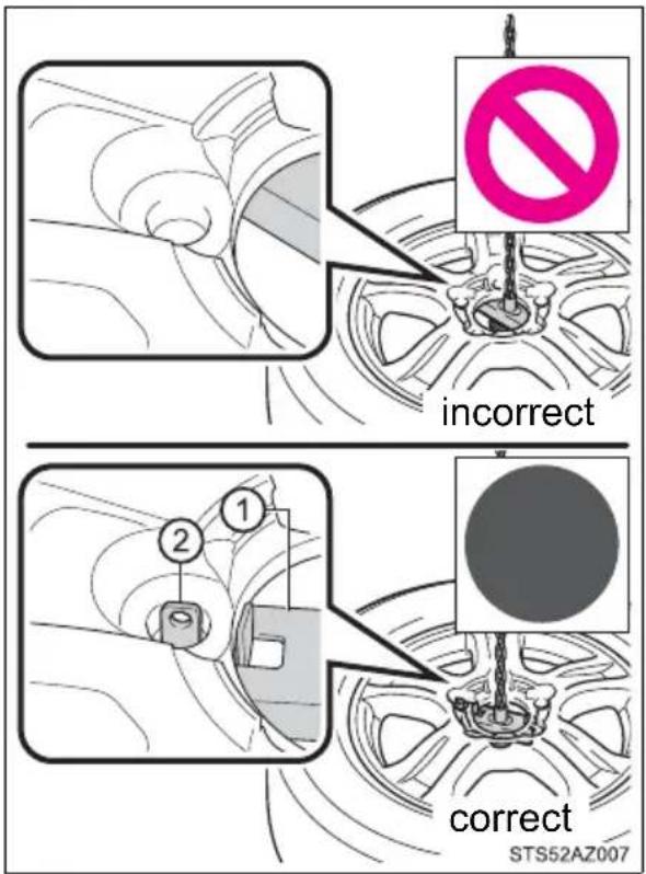
Tightening torque:
34.7 ft·lbf (46.6 N·m, 4.8 kgf·m)
3 Confirm it is not loose after tightening:
① Push and pull the tire
② Try rotating
Visually check to ensure tire is not hung on surrounding parts.
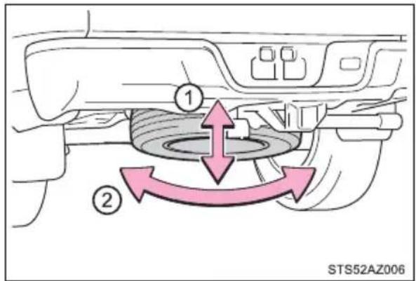
If looseness or misassembly exists, repeat step 2 and step . 3
4 Repeat step ,3any time the tire is lowered or disturbed.
5 Stow the tools and jack securely.
■The temporary spare tire
- The temporary spare tire is identified by the “TEMPORARY USE ONLY” marking on the disc wheel and/or tire sidewall.
Use the temporary spare tire temporarily, and only in an emergency.
● Make sure to check the tire inflation pressure of the temporary spare tire. (→P. 548)
■When reinstalling the wheel ornament (on some models)
→P. 446
■When using the temporary spare tire
As the temporary spare tire is not equipped with the tire pressure warning valve and transmitter, low inflation pressure of the spare tire will not be indicated by the tire pressure warning system. Also, if you replace the temporary spare tire after the tire pressure warning light comes on, the light remains on.
If you have a flat rear tire on a road covered with snow or ice
Install the temporary spare tire on one of the front wheels of the vehicle. Perform the following steps and fit tire chains to the rear tires:
1 Replace a front tire with the temporary spare tire.
2 Replace the flat rear tire with the tire removed from the front of the vehicle.
3 Fit tire chains to the rear tires.

WARNING
■When using the temporary spare tire
- Remember that the temporary spare tire provided is specifically designed for use with your vehicle. Do not use your temporary tire on another vehicle.
- Do not use more than one temporary spare tires simultaneously.
- Replace the temporary spare tire with a standard tire as soon as possible.
- Avoid sudden acceleration, abrupt steering, sudden braking and shifting operations that cause sudden engine braking.
■When the spare tire is attached
The vehicle speed may not be correctly detected, and the following systems may not operate correctly:
- ABS & Brake assist
• VSC
• TRAC
• AUTO LSD - Pre-Collision System*
• Automatic High Beam*
• LDA (Lane Departure Alert)*
• Dynamic radar cruise control*
- Cruise control*
- Navigation system*
*: If equipped
Also, not only can the following system not be utilized fully, but it may even negatively affect the drive-train components:
- 4WD system
■Speed limit when using the temporary spare tire
Do not drive at speeds in excess of 50 mph (80 km/h) when a temporary spare tire is installed on the vehicle.
The temporary spare tire is not designed for driving at high speeds. Failure to observe this precaution may lead to an accident causing death or serious injury.

NOTICE
■ Do not drive the vehicle with a flat tire
Do not continue driving with a flat tire.
Driving even a short distance with a flat tire can damage the tire and the wheel beyond repair.
- Driving with tire chains and the temporary spare tire
Do not fit tire chains to the temporary spare tire.
Tire chains may damage the vehicle body and adversely affect driving performance.
■When replacing the tires
When removing or fitting the wheels, tires or the tire pressure warning valve and transmitter, contact your Toyota dealer as the tire pressure warning valve and transmitter may be damaged if not handled correctly.
■ To avoid damage to the tire pressure warning valves and transmitters
When a tire is repaired with liquid sealants, the tire pressure warning valve and transmitter may not operate properly. If a liquid sealant is used, contact your Toyota dealer or other qualified service shop as soon as possible. Make sure to replace the tire pressure warning valve and transmitter when replacing the tire. (→P. 427)
If the engine will not start
If the engine will not start even though correct starting procedures are being followed ( P. 217), consider each of the following points.
The engine will not start even though the starter motor operates normally.
One of the following may be the cause of the problem:
- There may not be sufficient fuel in the vehicle's tank. Refuel the vehicle.
●The engine may be flooded. Try to restart the engine again following correct starting procedures. (→P. 217)
●There may be a malfunction in the engine immobilizer system. (→P. 85)
The starter motor turns over slowly, the interior lights and headlights are dim, or the horn does not sound or sounds at a low volume.
One of the following may be the cause of the problem:
● The battery may be discharged. (→P. 525)
●The battery terminal connections may be loose or corroded.
The starter motor does not turn over (vehicles with a smart key system)
The engine starting system may be malfunctioning due to an electrical problem such as an open circuit or a blown fuse. However, an interim measure is available to start the engine. (→P. 522)
The starter motor does not turn over, the interior lights and headlights do not turn on, or the horn does not sound.
One of the following may be the cause of the problem:
●One or both of the battery terminals may be disconnected.
● The battery may be discharged. (→P. 525)
Contact your Toyota dealer if the problem cannot be repaired, or if repair procedures are unknown.
Emergency start function (vehicles with a smart key system)
When the engine does not start, the following steps can be used as an interim measure to start the engine if the engine switch is functioning normally:
1 Set the parking brake.
2 Shift the shift lever to P.
3 Turn the engine switch to ACC.
4 Press and hold the engine switch for about 15 seconds while depressing the brake pedal firmly.
Even if the engine can be started using the above steps, the system may be malfunctioning. Have the vehicle inspected by your Toyota dealer.
If the electronic key does not operate properly (vehicles with a smart key system)
If communication between the electronic key and vehicle is interrupted ( P. 142) or the electronic key cannot be used because the battery is depleted, the smart key system and wireless remote control cannot be used. In such cases, the doors can be opened and the engine can be started by following the procedure below.
Locking and unlocking the doors
Use the mechanical key ( P. 122) in order to perform the following operations:
① Locks all the doors
② Unlocks all the doors
Turning the key rearward unlocks the driver's door. Turning the key once again unlocks the other doors.
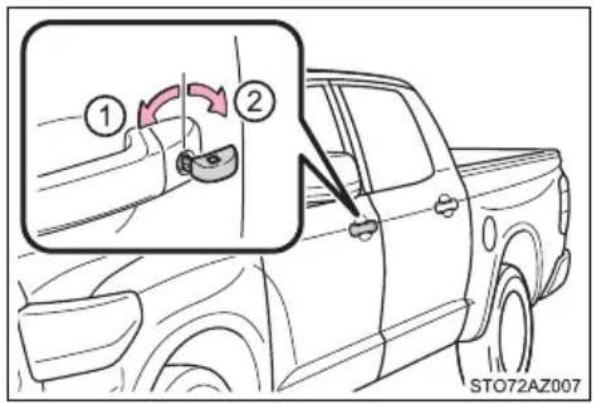
Starting the engine
1 Ensure that the shift lever is in P and depress the brake pedal.
2 Touch the Toyota emblem side of the electronic key to the engine switch.
If any of the doors is opened or closed while the key is being touched to the switch, an alarm will sound to indicate that the start function cannot detect the key.
3 Press the engine switch.
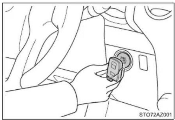
natural_image
Line drawing of a hand inserting a small device into a car interior (no text or symbols)In the event that the engine still cannot be started, contact your Toyota dealer.
■Stopping the engine
Shift the shift lever to P and press the engine switch as you normally do when stopping the engine.
■Replacing the key battery
As the above procedure is a temporary measure, it is recommended that the electronic key battery be replaced immediately when the battery is depleted. ( P. 451)
■Changing engine switch modes
Within 10 seconds of the buzzer sounding, release the brake pedal and press the engine switch.
The engine does not start and modes will be changed each time the switch is pressed. ( P. 220)
If the vehicle battery is discharged
The following procedures may be used to start the engine if the vehicle's battery is discharged.
You can also call your Toyota dealer or a qualified repair shop.
If you have a set of jumper (or booster) cables and a second vehicle with a 12-volt battery, you can jump start your vehicle by following the steps below.
1 Confirm that the key is being carried.
When connecting the jumper (or booster) cables, depending on the situation, the alarm may activate and the doors may lock. (→P. 96)
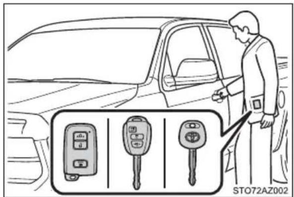
2 Open the hood. (→P. 414)
3 Connect the jumper cables according to the following procedure:
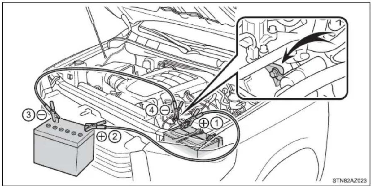
① Connect a positive jumper cable clamp to the positive (+) battery terminal on your vehicle.
② Connect the clamp on the other end of the positive cable to the positive (+) battery terminal on the second vehicle.
③ Connect a negative cable clamp to the negative (-) battery terminal on the second vehicle.
④ Connect the clamp at the other end of the negative cable to a solid, stationary, unpainted metallic point away from the battery and any moving parts, as shown in the illustration.
4 Start the engine of the second vehicle. Increase the engine speed slightly and maintain at that level for approximately 5 minutes to recharge the battery of your vehicle.
5 Vehicles with a smart key system only: Open and close any of the doors of your vehicle with the engine switch off.
6 Maintain the engine speed of the second vehicle and start the engine of your vehicle by turning the engine switch to ON.
7 Once the vehicle's engine has started, remove the jumper cables in the exact reverse order from which they were connected.
Once the engine starts, have the vehicle inspected at your Toyota dealer as soon as possible.
■ Starting the engine when the battery is discharged
The engine cannot be started by push-starting.
■To prevent battery discharge
● Turn off the headlights and the audio system while the engine is off.
● Turn off any unnecessary electrical components when the vehicle is running at a low speed for an extended period, such as in heavy traffic.
■When the battery is removed or discharged
The moon roof must be initialized. (→P. 181)
■ Charging the battery
The electricity stored in the battery will discharge gradually even when the vehicle is not in use, due to natural discharge and the draining effects of certain electrical appliances. If the vehicle is left for a long time, the battery may discharge, and the engine may be unable to start. (The battery recharges automatically during driving.)
■When recharging or replacing the battery
- Vehicles with a smart key system: In some cases, it may not be possible to unlock the doors using the smart key system when the battery is discharged. Use the wireless remote control or the mechanical key to lock or unlock the doors.
● The engine may not start on the first attempt after the battery has recharged but will start normally after the second attempt. This is not a malfunction. - Vehicles with a smart key system: The engine switch mode is memorized by the vehicle. When the battery is reconnected, the system will return to the mode it was in before the battery was discharged. Before disconnecting the battery, turn the engine switch off.
If you are unsure what mode the engine switch was in before the battery discharged, be especially careful when reconnecting the battery.

WARNING
■Avoiding battery fires or explosions
Observe the following precautions to prevent accidentally igniting the flammable gas that may be emitted from the battery:
● Make sure each jumper cable is connected to the correct terminal and that it is not unintentionally in contact with any other than the intended terminal.
- Do not allow the + and - clamps of the jumper cables to come into contact with each other.
- Do not smoke, use matches, cigarette lighters or allow open flame near the battery.
Battery precautions
The battery contains poisonous and corrosive acidic electrolyte, while related parts contain lead and lead compounds. Observe the following precautions when handling the battery:
- When working with the battery, always wear safety glasses and take care not to allow any battery fluids (acid) to come into contact with skin, clothing or the vehicle body.
- Do not lean over the battery.
- In the event that battery fluid comes into contact with the skin or eyes, immediately wash the affected area with water and seek medical attention. Place a wet sponge or cloth over the affected area until medical attention can be received.
● Always wash your hands after handling the battery support, terminals, and other battery-related parts. - Do not allow children near the battery.

NOTICE
■When handling jumper cables
When connecting the jumper cables, ensure that they do not become entangled in the cooling fan or belt.
If your vehicle overheats
The following may indicate that your vehicle is overheating:
● The needle of the engine coolant temperature gauge ( P. 105) enters the red zone or a loss of engine power is experienced. (For example, the vehicle speed does not increase.)
●“ENGINE COOLANT OVERTEMP” is shown on the multi-information display.
●Steam comes out from under the hood.
Correction procedures
1 Stop the vehicle in a safe place and turn off the air conditioning system, and then stop the engine.
2 If you see steam: Carefully lift the hood after the steam subsides.
If you do not see steam:
Carefully lift the hood.
3 After the engine has cooled down sufficiently, inspect the hoses and radiator core (radiator) for any leaks.
If a large amount of coolant leaks, immediately contact your Toyota dealer.
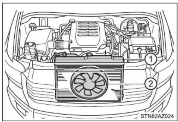
natural_image
Line drawing of a car's front engine bay with numbered components (no text or symbols)4 The coolant level is satisfactory if it is between the "FULL" and "LOW" lines on the reservoir.
① Reservoir
② “FULL”
③ “LOW”
④ Radiator cap
5 Add coolant if necessary.
Water can be used in an emergency if coolant is unavailable.
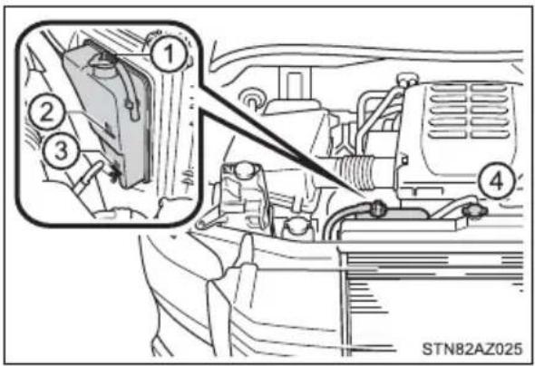
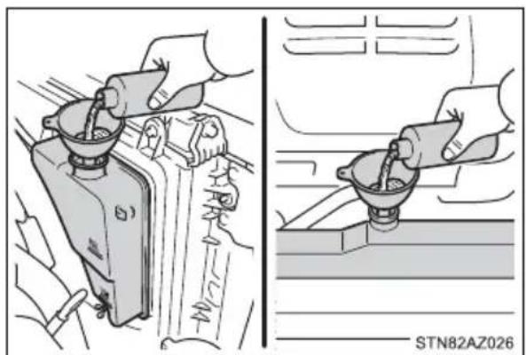
6 Start the engine to check that the radiator cooling fan operates and to check for coolant leaks from the radiator or hoses.
7 If the fan is not operating:
Stop the engine immediately and contact your Toyota dealer.
If the fan is operating:
Have the vehicle inspected at the nearest Toyota dealer.

WARNING
■When inspecting under the hood of your vehicle
Observe the following precautions.
Failure to do so may result in serious injury such as burns.
- If steam is seen coming from under the hood, do not open the hood until the steam has subsided. The engine compartment may be very hot.
- Keep hands and clothing away from the fans, etc., while the engine is running.
- Do not loosen the radiator cap and the coolant reservoir cap while the engine and radiator are hot.
High temperature steam or coolant could spray out.

NOTICE
■When adding engine coolant
Add coolant slowly after the engine has cooled down sufficiently. Adding cool coolant to a hot engine too quickly can cause damage to the engine.
■To prevent damage to the cooling system
Observe the following precautions:
● Avoid contaminating the coolant with foreign matter (such as sand or dust, etc.).
- Do not use any coolant additives.
If the vehicle becomes stuck
Carry out the following procedures if the tires spin or the vehicle becomes stuck in mud, dirt or snow:
1 Stop the engine. Set the parking brake and shift the shift lever to P.
2 Remove the mud, snow or sand from around the rear wheels.
3 Place wood, stones or some other material to help provide traction under the rear wheels.
4 Restart the engine.
5 Shift the shift lever to D or R and release the parking brake. Then, while exercising caution, depress the accelerator pedal.
■When it is difficult to free the vehicle
Press to turn off TRAC.
Turn off TRAC and/or VSC if these functions are hampering your attempts to free the vehicle. (→P. 321, 323)

WARNING
■When attempting to free a stuck vehicle
If you choose to push the vehicle back and forth to free it, make sure the surrounding area is clear to avoid striking other vehicles, objects or people. The vehicle may also lunge forward or lunge back suddenly as it becomes free. Use extreme caution.
■When shifting the shift lever
Be careful not to shift the shift lever with the accelerator pedal depressed. This may lead to unexpected rapid acceleration of the vehicle that may cause an accident resulting in death or serious injury.

NOTICE
■To avoid damage to the transmission and other components
● Avoid spinning the rear wheels and depressing the accelerator pedal more than necessary.
- If the vehicle remains stuck even after these procedures are performed, the vehicle may require towing to be freed.
When a warning message for the automatic transmission fluid temperature is displayed while attempting to free a stuck vehicle, immediately remove your foot from the accelerator pedal and wait until the warning message disappears. Otherwise, the transmission may become damaged. (→P. 493)
Vehicle specifications
8
8-1. Specifications
Maintenance data
(fuel, oil level, etc.)...... 536
Fuel information 551
Tire information 554
8-2. Customization
Customizable features ..... 564
8-3. Items to initialize
Items to initialize .... 574
Maintenance data (fuel, oil level, etc.)
Dimensions
2WD models
| Cab type Double Cab CrewMax | |||
| Bed type Standard Long Short | |||
| Overall length | 228.9 in. (5815 mm) | 247.8 in. (6295 mm) | 228.9 in. (5815 mm) |
| Overall width 79.9 in. (2030 mm) | |||
| Overall height*1 | 78.3 in. (1990 mm)*2 | 78.1 in. (1985 mm)*2 | |
| 78.1 in. (1985 mm)*3,*4 | 78.0 in. (1980mm)*3,*4 | ||
| Wheelbase | 145.6 in. (3700 mm) | 164.5 in. (4180 mm) | 145.6 in. (3700 mm) |
| Front tread 67.9 | in. (1725 mm) | ||
| Rear tread 67.9 | in. (1725 mm) | ||
*1: Unladen vehicle
*2: P255/70R18 tires
*3: P275/65R18 tires
*4: P275/55R20 tires
4WD models
| Cab type Double Cab CrewMax | |||
| Bed type Standard Long Short | |||
| Overall length | 228.9 in. (5815 mm) | 247.8 in. (6295 mm) | 228.9 in. (5815 mm) |
| Overall width 79.9 in. (2030 mm) | |||
| Overall height*1 | 78.7 in. (2000 mm)*2 | 78.6 in. (1995 mm)*2 | |
| 78.6 in. (1995 mm)*3,*4 | 78.3 in. (1990mm)*3,*4 | ||
| Wheelbase | 145.6 in. (3700 mm) | 164.5 in. (4180 mm) | 145.6 in. (3700 mm) |
| Front tread 67.9 | in. (1725 mm) | ||
| Rear tread 67.9 | in. (1725 mm) | ||
*1: Unladen vehicle
*2: P255/70R18 tires
*3: P275/65R18 tires
*4: P275/55R20 tires
Seating capacity
| Seating capacity | Vehicles with front separated type seats | Vehicles with front bench type seat |
| 5 (Front 2, Rear 3) 6 (Front 3, Rear 3) | ||
Vehicle capacity weight
▶ Double Cab models
| Model code*1 | Engine | Driving system | Bed type | Vehicle capacity weight (Occupants + lug-gage) |
| USK51L-CRTSKA | 3UR-FE engine | 2WD | Standard | 1605 lb. (730 kg) |
| 1540 lb. (700 kg)*2 | ||||
| 1425 lb. (645 kg)*3 | ||||
| USK51L-CRTLKA | 1570 lb. (710 kg) | |||
| 1505 lb. (680 kg)*2 | ||||
| 1385 lb. (630 kg)*3 | ||||
| USK52L-CHTSKA | Long | 1580 lb. (715 kg) | ||
| 1515 lb. (690 kg)*2 | ||||
| 1400 lb. (635 kg)*3 | ||||
| USK56L-CRTSKA | 4WD | Standard | 1500 lb. (680 kg) | |
| 1435 lb. (650 kg)*2 | ||||
| 1320 lb. (600 kg)*3 | ||||
| USK56L-CRTLKA | 1485 lb. (675 kg) | |||
| 1420 lb. (645 kg)*2 | ||||
| 1300 lb. (590 kg)*3 | ||||
| USK57L-CHTSKA | Long | 1475 lb. (670 kg) | ||
| 1410 lb. (640 kg)*2 | ||||
| 1290 lb. (585 kg)*3 |
^*1 : The model code is indicated on the Certification Label. ( P. 541)
*2: Vehicles with towing package
*3: Vehicles with towing package and large fuel tank
▶ CrewMax models
| Model code*1 | Engine | Driving system | Bed type | Vehicle capacity weight (Occupants + luggage) |
| USK51L-PSTSKA | 3UR-FE engine | 2WD | Short | 1545 lb. (700 kg) |
| 1510 lb. (685 kg)*2 | ||||
| 1480 lb. (670 kg)*3 | ||||
| 1360 lb. (620 kg)*4 | ||||
| 1445 lb. (655 kg)*5 | ||||
| 1325 lb. (600 kg)*6 | ||||
| USK51L-PSTLKA | 1510 lb. (685 kg) | |||
| 1475 lb. (670 kg)*2 | ||||
| 1445 lb. (655 kg)*3 | ||||
| 1325 lb. (600 kg)*4 | ||||
| 1410 lb. (640 kg)*5 | ||||
| 1290 lb. (585 kg)*6 | ||||
| USK51L-PSTZKA | 1495 lb. (680 kg) | |||
| 1460 lb. (665 kg)*2 | ||||
| 1430 lb. (650 kg)*3 | ||||
| 1315 lb. (595 kg)*4 | ||||
| 1395 lb. (635 kg)*5 | ||||
| 1280 lb. (580 kg)*6 | ||||
| USK56L-PSTSKA | 3UR-FE engine | 4WD Short | 1450 lb. (660 kg) | |
| 1415 lb. (640 kg)*2 | ||||
| 1385 lb. (630 kg)*3 | ||||
| 1270 lb. (575 kg)*4 | ||||
| 1350 lb. (610 kg)*5 | ||||
| 1235 lb. (560 kg)*6 | ||||
| USK56L-PSTLKA | 1400 lb. (635 kg) | |||
| 1365 lb. (620 kg)*2 | ||||
| 1335 lb. (605 kg)*3 | ||||
| 1220 lb. (555 kg)*4 | ||||
| 1300 lb. (590 kg)*5 | ||||
| 1185 lb. (535 kg)*6 | ||||
| USK56L-PSTZKA | 1405 lb. (635 kg) | |||
| 1370 lb. (620 kg)*2 | ||||
| 1340 lb. (605 kg)*3 | ||||
| 1220 lb. (555 kg)*4 | ||||
| 1305 lb. (590 kg)*5 | ||||
| 1185 lb. (540 kg)*6 | ||||
*1: The model code is indicated on the Certification Label. (→P. 541)
^*2 : Vehicles with electric moon roof
*3: Vehicles with towing package
*4: Vehicles with towing package and large fuel tank
*5: Vehicles with towing package and electric moon roof
*6: Vehicles with towing package, electric moon roof and large fuel tank
Vehicle identification
■Vehicle identification number
The vehicle identification number (VIN) is the legal identifier for your vehicle. This is the primary identification number for your Toyota. It is used in registering the ownership of your vehicle.
This number is stamped on the top left of the instrument panel.
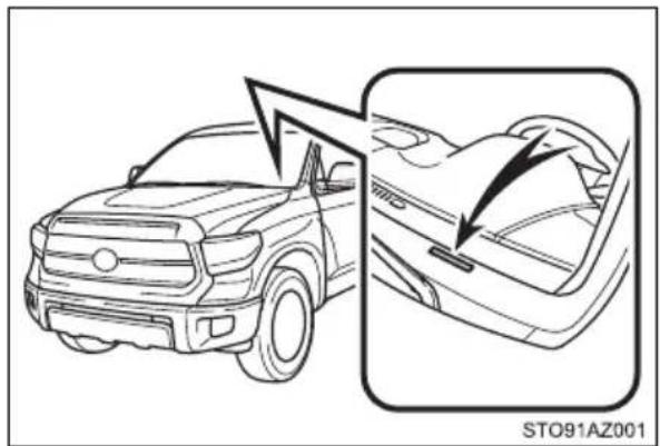
natural_image
Line drawing of a Toyota T-9 car showing front and side views (no text or symbols)This number is also on the Certification Label.
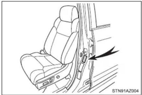
natural_image
Line drawing of a car seat with a double door and belt, showing no text or symbolsEngine number
The engine number is stamped on the engine block as shown.
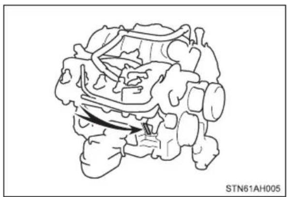
natural_image
Diagram of a brain with highlighted region and arrow, no text or symbols presentEngine
| Model 3UR-FE | |
| Type 8-cylinder V-type, 4-cycle, gasoline | |
| Bore and stroke | 3.70 × 4.02 in. (94.0 × 102.0 mm) |
| Displacement 345.6 cu.in. | (5663 cm 3) |
| Drive belt tension Automatic adjustment | |
| Valve clearance (engine cold) | Automatic adjustment |
Fuel
| Fuel type Unleaded gasoline | line only |
| Octane rating(Unleaded gasoline) | 87 (Research Octane Number 91) or higher |
| Fuel tank capacity(Reference) | Standard fuel tank:26.4 gal. (100.0 L, 22.0 Imp.gal.)Large fuel tank:38.0 gal. (144.0 L, 31.7 Imp.gal.) |
Lubrication system
| Oil capacity(Drain and refill - reference*) | |
| With filter | 8.5 qt. (8.0 L, 7.0 Imp.qt.) |
| Without filter | 7.9 qt. (7.5 L, 6.6 Imp.qt.) |
*: The engine oil capacity is a reference quantity to be used when changing the engine oil. Warm up and turn off the engine, wait more than 5 minutes, and check the oil level on the dipstick.
■ Engine oil selection
"Toyota Genuine Motor Oil" is used in your Toyota vehicle. Use Toyota approved "Toyota Genuine Motor Oil" or equivalent to satisfy the following grade and viscosity.
Oil grade: ILSAC GF-5 multigrade engine oil
Recommended viscosity: SAE 0W-20
SAE 0W-20 is the best choice for good fuel economy and good starting in cold weather.
If SAE 0W-20 is not available, SAE 5W-20 oil may be used. However, it must be replaced with SAE 0W-20 at the next oil change.
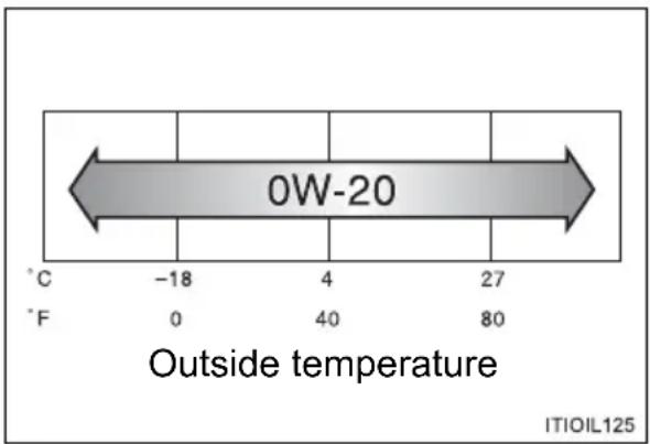
Oil viscosity (0W-20 is explained here as an example):
- The 0W in 0W-20 indicates the characteristic of the oil which allows cold startability. Oils with a lower value before the W allow for easier starting of the engine in cold weather.
- The 20 in 0W-20 indicates the viscosity characteristic of the oil when the oil is at high temperature. An oil with a higher viscosity (one with a higher value) may be better suited if the vehicle is operated at high speeds, or under extreme load conditions.
How to read oil container label:
The International Lubricant Specification Advisory Committee (ILSAC) Certification Mark is added to some oil containers to help you select the oil you should use.

Cooling system
| Capacity | ▸ Vehicles without towing package11.4 qt. (10.8 L, 9.5 Imp.qt.)▸ Vehicles with towing package12.4 qt. (11.7 L, 10.3 Imp.qt.) |
| Coolant type | Use either of the following.“Toyota Super Long Life Coolant”Similar high-quality ethylene glycol-based non-silicate, non-amine, non-nitrite, and non-borate coolant with long-life hybrid organic acid technologyDo not use plain water alone. |
Ignition system
| Spark plugMake DENSO SK20HR11 | |
| Gap 0.043 in. (1.1 mm) |

NOTICE
■Iridium-tipped spark plugs
Use only iridium-tipped spark plugs. Do not adjust the spark plug gap.
Electrical system
| BatteryOpen voltage at 68°F(20°C): | 12.6 — 12.8 V Fully charged12.2 — 12.4 V Half charged11.8 — 12.0 V Discharged(Voltage is checked 20 minutes after the engine and all lights are turned off.) |
| Charging rates 5 A max. |
Differential
| Oil capacity | Front (4WD models) 2.2 qt. (2.05 | L, 1.8 Imp.qt.) | |
| Rear | Double Cab models | ► With standard bed3.8 qt. (3.60 L, 3.2 Imp.qt.)► With long bed4.0 qt. (3.75 L, 3.3 Imp.qt.) | |
| CrewMax models | ► 2WD models4.0 qt. (3.75 L, 3.3 Imp.qt.)► 4WD models3.8 qt. (3.60 L, 3.2 Imp.qt.) | ||
| Oil type and viscosity* | Toyota Genuine Differential Gear Oil LT 75W-85 GL-5 or equivalent | ||
*: Your Toyota vehicle is filled with "Toyota Genuine Differential Gear Oil" at the factory. Use Toyota approved "Toyota Genuine Differential Gear Oil" or an equivalent oil of matching quality to satisfy the above specification. Please contact your Toyota dealer for further details.
Automatic transmission
| Fluid capacity* 11.7 qt. (11.1 L, 9.8 Imp.qt.) | |
| Fluid type Toyota Genuine ATF WS |
*: The fluid capacity is the quantity of reference. If replacement is necessary, contact your Toyota dealer.

NOTICE
■Transmission fluid type
Using transmission fluid other than the above type may cause abnormal noise or vibration, or damage the transmission of your vehicle.
Transfer (4WD models)
| Oil capacity 1.6 qt. (1.5 L, 1.3 Imp. qt.) | |
| Oil type | Toyota Genuine Transfer Gear oil LF or equivalent |
| Recommended oil viscosity SAE | 75W |
Brakes
| Pedal clearance*1 | 4.1 in. (104 mm) Min. |
| Pedal free play | 0.04 — 0.24 in. (1 — 6 mm) |
| Brake pad wear limit 0.04 in. (1.0 mm) | mm) |
| Parking brake lining wear limit 0.04 in. (1.0 mm) | |
| Parking brake pedal travel*2 | 6 — 9 clicks |
| Fluid type FMVSS No. 116 DOT 3 or SAE J1703 | |
*1: Minimum pedal clearance when depressed with a force of 110 lbf (490 N, 50 kgf) with the engine running.
*2: Parking brake pedal travel when depressed with a force of 67.1 lbf (300 N, 30.6 kgf).
Steering
| Free play Less than 1.2 in. (30 mm) | |
| Power steering fluid type | Automatic transmission fluid DEXRON® II or III |
Tires and wheels
▶ Type A
| Tire size P255/70R18 112T | |
| Tire inflation pressure(Recommended cold tire inflation pressure) | Front tires:30 psi (210 kPa, 2.1 kgf/cm2 or bar)Rear tires:33 psi (230 kPa, 2.3 kgf/cm2 or bar)Spare tire:33 psi (230 kPa, 2.3 kgf/cm2 or bar) |
| Wheel size 18 × 8J | |
| Wheel nut torque | Steel wheels:154 ft·lbf (209 N·m, 21.3 kgf·m)Aluminum wheels:97 ft·lbf (131 N·m, 13.4 kgf·m) |
▶ Type B
| Tire size P275/65R18 114T | |
| Tire inflation pressure(Recommended cold tire inflation pressure) | Front tires:30 psi (210 kPa, 2.1 kgf/cm2 or bar)Rear tires:33 psi (230 kPa, 2.3 kgf/cm2 or bar)Spare tire:33 psi (230 kPa, 2.3 kgf/cm2 or bar) |
| Wheel size 18 × 8J | |
| Wheel nut torque | Steel wheels:154 ft·lbf (209 N·m, 21.3 kgf·m)Aluminum wheels:97 ft·lbf (131 N·m, 13.4 kgf·m) |
▶ Type C
| Tire size | P275/65R18 114T,P255/70R18 112T (spare tire) |
| Tire inflation pressure(Recommended coldtire inflation pressure) | Front tires:30 psi (210 kPa, 2.1 kgf/cm2 or bar)Rear tires:33 psi (230 kPa, 2.3 kgf/cm2 or bar)Spare tire:33 psi (230 kPa, 2.3 kgf/cm2 or bar) |
| Wheel size | 18 × 8J,18 × 8J (spare wheel) |
| Wheel nut torque | Steel wheels:154 ft·lbf (209 N·m, 21.3 kgf·m)Aluminum wheels:97 ft·lbf (131 N·m, 13.4 kgf·m) |
▶ Type D
| Tire size | P275/55R20 111H,P255/70R18 112T (spare tire) |
| Tire inflation pressure(Recommended coldtire inflation pressure) | Front tires:30 psi (210 kPa, 2.1 kgf/cm2 or bar)Rear tires:33 psi (230 kPa, 2.3 kgf/cm2 or bar)Spare tire:33 psi (230 kPa, 2.3 kgf/cm2 or bar) |
| Wheel size | 20 × 8J,18 × 8J (spare wheel) |
| Wheel nut torque | Steel wheels:154 ft·lbf (209 N·m, 21.3 kgf·m)Aluminum wheels:97 ft·lbf (131 N·m, 13.4 kgf·m) |
Light bulbs
| Light Bulbs Bulb No. | W Type | |||
| Exterior | Headlights*2 | HB2 60/55 A | ||
| Front fog lights (bulb type)*1 | H16 19 B | |||
| Front side marker lights W5W | 5 D | |||
| Front turn signal lights/parking lights*2 | 4157NAK | 27/8 C | ||
| Front turn signal lights*3 | 7444NA | 28 C | ||
| Rear turn signal lights | 921 | 16 D | ||
| Stop/tail and rear side marker lights | 3157KX | 27/8 D | ||
| Back-up lights | 7440 | 21 | D | |
| License plate lights | W5W 5 D | |||
| High mounted stoplight and cargo lamp | 921 | 16 | D | |
| Outer foot light | — | 5 D | ||
| Interior | Vanity lights | 7065 | 5 E | |
| Personal/interior lightsFrontRear | W5WW5W | 55 | DD | |
| Foot well lighting | — | 1.4 | D | |
*1: If equipped
*2: Vehicles with bulb type headlights
*3: Vehicles with LED type headlights
A: HB2 halogen bulbs
B: H16 halogen bulbs
C: Wedge base bulbs (amber)
D: Wedge base bulbs (clear)
E: Double end bulbs
Fuel information
You must only use unleaded gasoline.
Select octane rating 87 (Research Octane Number 91) or higher. Use of unleaded gasoline with an octane rating lower than 87 may result in engine knocking. Persistent knocking can lead to engine damage.
At minimum, the gasoline you use should meet the specifications of ASTM D4814 in the U.S.A.
Gasoline quality
In very few cases, driveability problems may be caused by the brand of gasoline you are using. If driveability problems persist, try changing the brand of gasoline. If this does not correct the problem, consult your Toyota dealer.
■ Recommendation of the use of gasoline containing detergent additives
● Toyota recommends the use of gasoline that contains detergent additives to avoid build-up of engine deposits.
- All gasoline sold in the U.S.A. contains minimum detergent additives to clean and/or keep clean intake systems, per EPA's lowest additives concentration program.
● Toyota strongly recommends the use of Top Tier Detergent Gasoline. For more information on Top Tier Detergent Gasoline and a list of marketers, please go to the official website www.toptiergas.com.
■Recommendation of the use of low emissions gasoline
Gasolines containing oxygenates such as ethers and ethanol, as well as reformulated gasolines, are available in some cities. These fuels are typically acceptable for use, providing they meet other fuel requirements.
Toyota recommends these fuels, since the formulations allow for reduced vehicle emissions.
■Non-recommendation of the use of blended gasoline
- Use only gasoline containing up to 15% ethanol. DO NOT use any flex-fuel or gasoline that could contain more than 15% ethanol, including from any pump labeled E30, E50, E85 (which are only some examples of fuel containing more than 15% ethanol).
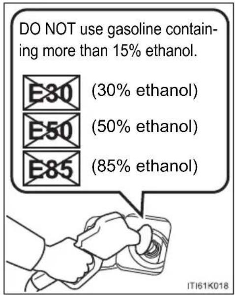
- If you use gasohol in your vehicle, be sure that it has an octane rating no lower than 87.
● Toyota does not recommend the use of gasoline containing methanol.
■Non-recommendation of the use of gasoline containing MMT
Some gasoline contains an octane enhancing additive called MMT (Methylcyclopentadienyl Manganese Tricarbonyl).
Toyota does not recommend the use of gasoline that contains MMT. If fuel containing MMT is used, your emission control system may be adversely affected.
The malfunction indicator lamp on the instrument cluster may come on. If this happens, contact your Toyota dealer for service.
If your engine knocks
- Consult your Toyota dealer.
● You may occasionally notice light knocking for a short time while accelerating or driving uphill. This is normal and there is no need for concern.

NOTICE
■Notice on fuel quality
- Do not use improper fuels. If improper fuels are used, the engine will be damaged.
- Do not use leaded gasoline.
Leaded gasoline can cause damage to your vehicle's three-way catalytic converters causing the emission control system to malfunction. - Do not use gasohol other than the type previously stated.
Other gasohol may cause fuel system damage or vehicle performance problems. - Using unleaded gasoline with an octane number or rating lower than the level previously stated will cause persistent heavy knocking.
At worst, this will lead to engine damage.
■Fuel-related poor driveability
If poor driveability (poor hot starting, vaporization, engine knocking, etc.) is encountered after using a different type of fuel, discontinue the use of that type of fuel.
■When refueling with gasohol
Take care not to spill gasohol. It can damage your vehicle's paint.
Tire information
Typical tire symbols
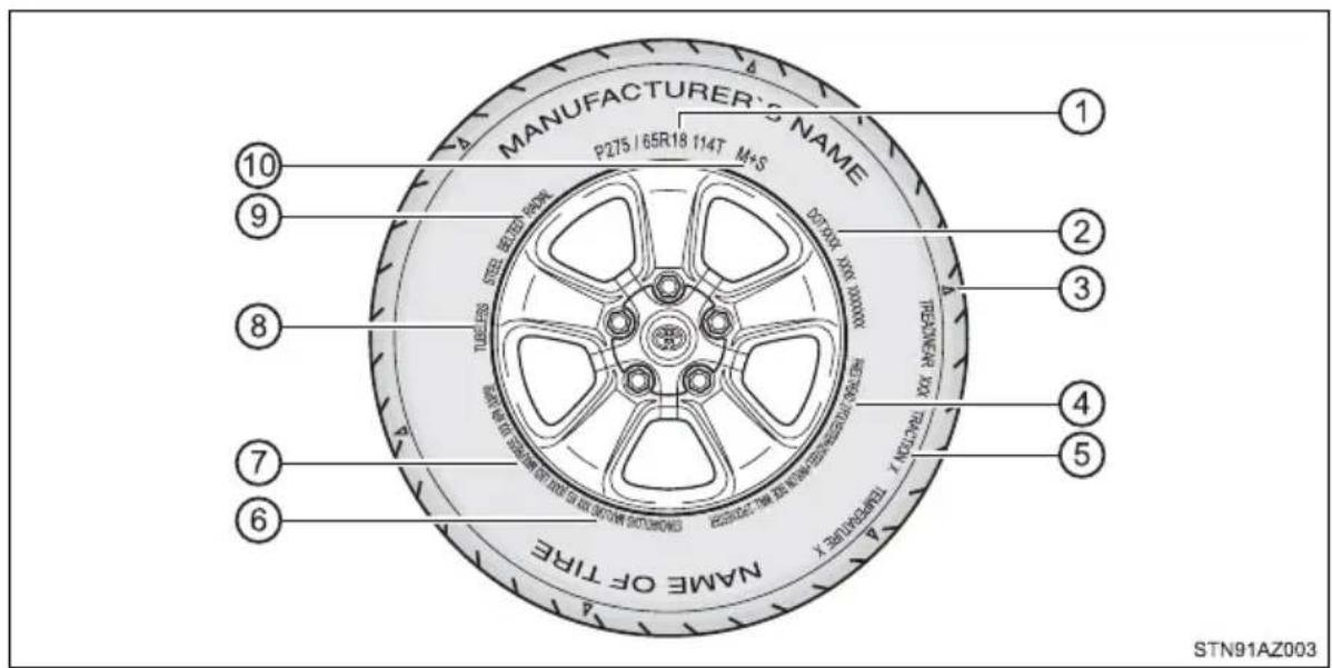
① Tire size ( P. 555)
② DOT and Tire Identification Number (TIN) ( P. 555)
③ Location of treadwear indicators ( P. 426)
④ Tire ply composition and materials
Plies are layers of rubber-coated parallel cords. Cords are the strands which form the plies in a tire.
⑤ Uniform tire quality grading
For details, see "Uniform Tire Quality Grading" that follows.
⑥ Load limit at maximum cold tire inflation pressure ( P. 559)
⑦ Maximum cold tire inflation pressure ( P. 559)
This means the pressure to which a tire may be inflated.
⑧ TUBELESS or TUBE TYPE
A tubeless tire does not have a tube and air is directly put into the tire. A tube type tire has a tube inside the tire and the tube maintains the air pressure.
⑨ Radial tires or bias-ply tires
A radial tire has "RADIAL" on the sidewall. A tire not marked "RADIAL" is a bias-ply tire.
⑩ Summer tire or all season tire ( P. 431)
An all season tire has "M+S" on the sidewall. A tire not marked "M+S" is a summer tire.
Typical DOT and Tire Identification Number (TIN)
▶ Type A ▶ Type B
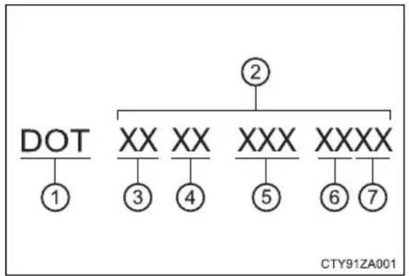
flowchart
graph TD
    A["DOT"] --> B["1"]
    A --> C["XX"]
    C --> D["3"]
    C --> E["XX"]
    E --> F["4"]
    E --> G["XXX"]
    G --> H["5"]
    G --> I["6"]
    G --> J["7"]
    K["②"] --> L["XXXX"]
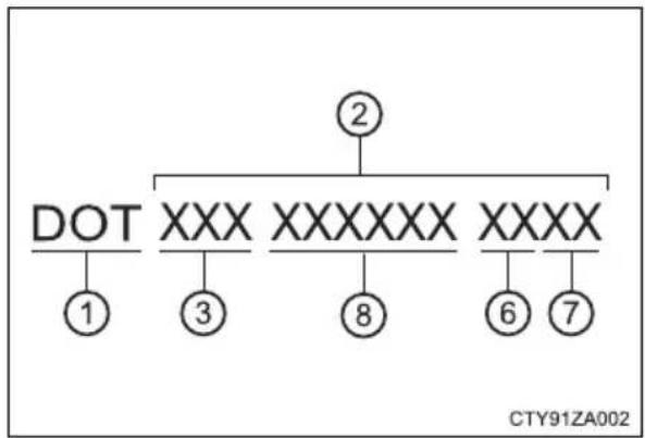
flowchart
graph TD
    A["②"] --> B["DOT"]
    A --> C["XXXX"]
    A --> D["XXXXXXXX"]
    A --> E["XXXX"]
    B --> F["①"]
    B --> G["③"]
    C --> H["⑧"]
    C --> I["⑥"]
    C --> J["⑦"]
① DOT symbol*
② Tire Identification Number (TIN)
③ Tire manufacturer's identification mark
④ Tire size code
⑤ Manufacturer's optional tire type code (3 or 4 letters)
⑥ Manufacturing week
⑦ Manufacturing year
⑧ Manufacturer's code
*: The DOT symbol certifies that the tire conforms to applicable Federal Motor Vehicle Safety Standards.
Tire size
■Typical tire size information
The illustration indicates typical tire size.
① Tire use
② Section width (millimeters)
③ Aspect ratio (tire height to section width)
④ Tire construction code (R = Radial, D = Diagonal)
⑤ Wheel diameter (inches)
$$ \begin{array}{l} (P = \text { Passenger car }, \ T = \text { Temporary use }) \end{array} $$
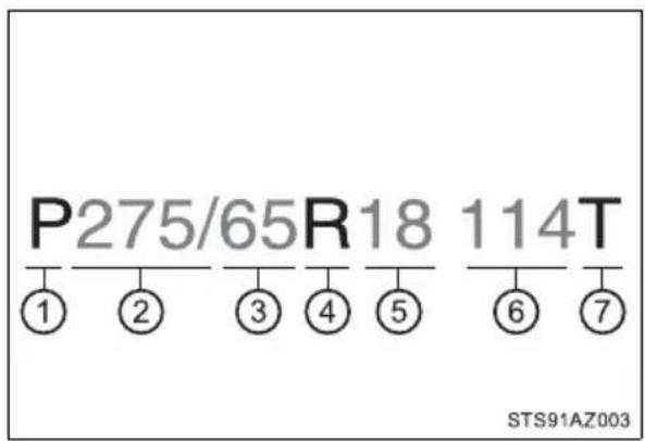
⑥ Load index (2 digits or 3 digits)
⑦ Speed symbol (alphabet with one letter)
Tire dimensions
① Section width
② Tire height
③ Wheel diameter

Tire section names
① Bead
② Sidewall
③ Shoulder
④ Tread
⑤ Belt
⑥ Inner liner
⑦ Reinforcing rubber
⑧ Carcass
⑨ Rim lines
⑩ Bead wires
⑪ Chafer
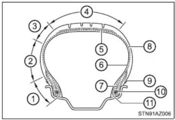
Uniform Tire Quality Grading
This information has been prepared in accordance with regulations issued by the National Highway Traffic Safety Administration of the U.S. Department of Transportation.
It provides the purchasers and/or prospective purchasers of Toyota vehicles with information on uniform tire quality grading.
Your Toyota dealer will help answer any questions you may have as you read this information.
■DOT quality grades
All passenger vehicle tires must conform to Federal Safety Requirements in addition to these grades. Quality grades can be found where applicable on the tire sidewall between tread shoulder and maximum section width.
For example: Treadwear 200 Traction AA Temperature A
Treadwear
The treadwear grade is a comparative rating based on the wear rate of the tire when tested under controlled conditions on a specified government test course.
For example, a tire graded 150 would wear one and a half (1 - 1/2) times as well on the government course as a tire graded 100. The relative performance of tires depends upon the actual conditions of their use. Performance may differ significantly from the norm due to variations in driving habits, service practices and differences in road characteristics and climate.
■Traction AA, A, B, C
The traction grades, from highest to lowest, are AA, A, B and C, and they represent the tire's ability to stop on wet pavement as measured under controlled conditions on specified government test surfaces of asphalt and concrete.
A tire marked C may have poor traction performance.
Warning: The traction grade assigned to this tire is based on braking (straight ahead) traction tests and does not include cornering (turning) traction.
■Temperature A, B, C
The temperature grades are A (the highest), B, and C, representing the tire's resistance to the generation of heat and its ability to dissipate heat when tested under controlled conditions on a specified indoor laboratory test wheel.
Sustained high temperature can cause the material of the tire to degenerate and reduce tire life, and excessive temperature can lead to sudden tire failure.
Grade C corresponds to a level of performance which all passenger car tires must meet under the Federal Motor Vehicle Safety Standard No. 109.
Grades B and A represent higher levels of performance on the laboratory test wheel than the minimum required by law.
Warning: The temperature grades of a tire assume that it is properly inflated and not overloaded.
Excessive speed, underinflation, or excessive loading, either separately or in combination, can cause heat buildup and possible tire failure.
Glossary of tire terminology
| Tire related term Meaning | |
| Cold tire inflation pressure | Tire pressure when the vehicle has been parked for three hours or more, or has not been driven more than 1 mile or 1.5 km under that condition |
| Maximum inflation pressure | The maximum cold inflated pressure to which a tire may be inflated, shown on the sidewall of the tire |
| Recommended inflation pressure | Cold tire inflation pressure recommended by a manufacturer |
| Accessory weight | The combined weight (in excess of those standard items which may be replaced) of automatic transmission, power steering, power brakes, power windows, power seats, radio and heater, to the extent that these items are available as factory-installed equipment (whether installed or not) |
| Curb weight | The weight of a motor vehicle with standard equipment, including the maximum capacity of fuel, oil and coolant, and if so equipped, air conditioning and additional weight optional engine |
| Maximum loaded vehicle weight | The sum of:(a) Curb weight(b) Accessory weight(c) Vehicle capacity weight(d) Production options weight |
| Normal occupant weight | 150 lb. (68 kg) times the number of occupants specified in the second column of Table 1* that follows |
| Occupant distribution | Distribution of occupants in a vehicle as specified in the third column of Table 1* below |
| Production options weight | The combined weight of installed regular production options weighing over 5 lb. (2.3 kg) in excess of the standard items which they replace, not previously considered in curb weight or accessory weight, including heavy duty brakes, ride levelers, roof rack, heavy duty battery, and special trim |
| Tire related term | Meaning |
| Rim | A metal support for a tire or a tire and tube assembly upon which the seated |
| Rim diameter (Wheel diameter) | Nominal diameter of the bead seat |
| Rim size designation Rim | diameter and width |
| Rim type designation | The industry manufacturer's designation for a rim by style or code |
| Rim width Nominal distance between rim flanges | |
| Vehicle capacity weight (Total load capacity) | The rated cargo and luggage load plus 150 lb. (68 kg) times the vehicle's designated seating capacity |
| Vehicle maximum load on the tire | The load on an individual tire that is determined by distributing to each axle its share of the maximum loaded vehicle weight, and dividing by two |
| Vehicle normal load on the tire | The load on an individual tire that is determined by distributing to each axle its share of curb weight, accessory weight, and normal occupant weight (distributed in accordance with Table 1* below), and dividing by two |
| Weather side | The surface area of the rim not covered by the inflated tire |
| Bead | The part of the tire that is made of steel wires, wrapped or reinforced by ply cords and that is shaped to fit the rim |
| Bead separation | A breakdown of the bond between components in the bead |
| Bias ply tire | A pneumatic tire in which the ply cords that extend to the beads are laid at alternate angles substantially less than 90 degrees to the centerline of the tread |
| Carcass | The tire structure, except tread and sidewall rubber which, when inflated, bears the load |
| Chunking | The breaking away of pieces of the tread or sidewall |
| Cord | The strands forming the plies in the tire |
| Cord separation | The parting of cords from adjacent rubber compounds |
| Cracking | Any parting within the tread, sidewall, or inner-liner of the tire extending to cord material |
| CT | A pneumatic tire with an inverted flange tire and rim system in which the rim is de with rim flanges pointed radially inward and the tire is designed to fit on the underside of the rim in a manner that encloses the rim flanges inside the air cavity of the tire |
| Extra load tire | A tire designed to operate at higher loads and at higher inflation pressures than the corresponding standard tire |
| Groove The space between two adjacent tread ribs | |
| Innerliner | The layer(s) forming the inside surface of a tubeless tire that contains the inflating medium within the tire |
| Innerliner separation | The parting of the innerliner from cord material in the carcass |
| Intended outboard sidewall | (a) The sidewall that contains a whitewall, bears white lettering, or bears manufacturer, brand, and/or model name molding that is higher or deeper than the same molding on the other sidewall of the tire, or (b) The outward facing sidewall of an asymmetrical tire that has a particular side that must always face outward when mounted on a vehicle |
| Light truck (LT) tire | A tire designated by its manufacturer as primarily intended for use on lightweight trucks or multipurpose passenger vehicles |
| Load rating | The maximum load that a tire is rated to carry for a given inflation pressure |
| Maximum load rating | The load rating for a tire at the maximum permissible inflation pressure for that tire |
| Maximum permissible inflation pressure | The maximum cold inflation pressure to which a tire may be inflated |
| Measuring rim | The rim on which a tire is fitted for physical dimension requirements |
signe
| Tire related term Meaning | |
| Open splice | Any parting at any junction of tread, sidewall, or innerliner that extends to cord material |
| Outer diameter The overall diameter of an inflated new tire | |
| Overall width | The linear distance between the exteriors of the sidewalls of an inflated tire, including elevations due to labeling, decorations, or protective bands or ribs |
| Passenger car tire | A tire intended for use on passenger cars, multipurpose passenger vehicles, and trucks, that have a gross vehicle weight rating (GVWR) of 10,000 lb. or less. |
| Ply A layer of rubber-coated parallel cords | |
| Ply separation | A parting of rubber compound between adjacent plies |
| Pneumatic tire | A mechanical device made of rubber, chemicals, fabric and steel or other materials, when mounted on an automotive wheel, provides the traction and contains the gas or fluid that sustains the load |
| Radial ply tire | A pneumatic tire in which the ply cords that extend to the beads are laid at substantially 90 degrees to the centerline of the tread |
| Reinforced tire | A tire designed to operate at higher loads and at higher inflation pressures than the corresponding standard tire |
| Section width | The linear distance between the exteriors of the sidewalls of an inflated tire, excluding elevations due to labeling, decoration, or protective bands |
| Sidewall | That portion of a tire between the tread and bead |
| Sidewall separation | The parting of the rubber compound from the cord material in the sidewall |
| Tire related term | Meaning |
| Snow tire | A tire that attains a traction index equal to or greater than 110, compared to the ASTM E-1136 Standard Reference Test Tire, when using the snow traction test as described in ASTM F-1805-00, Standard Test Method for Single Wheel Driving Traction in a Straight Line on Snow-and Ice-Covered Surfaces, and which is marked with an Alpine Symbol ( )on at least one sidewall |
| Testrim | The rim on which a tire is fitted for testing, and may be any rim listed as appropriate for use with that tire |
| Tread | That portion of a tire that comes into contact with the road |
| Tread rib | A tread section running circumferentially around a tire |
| Tread separation Pulling | away of the tread from the tire carcass |
| Treadwear indicators (TWI) | The projections within the principal grooves designed to give a visual indication of the degrees of wear of the tread |
| Wheel-holding fixture | The fixture used to hold the wheel and tire assembly securely during testing |
*: Table 1 — Occupant loading and distribution for vehicle normal load for various designated seating capacities
| Designated seating capacity, Number of occupants | Vehicle normal load, Number of occupants | Occupant distribution in a normally loaded vehicle |
| 2 through 4 | 2 | 2 in front |
| 5 through 10 | 3 | 2 in front, 1 in second seat |
| 11 through 15 | 5 | 2 in front, 1 in second seat, 1 in third seat, 1 in fourth seat |
| 16 through 20 | 7 | 2 in front, 2 in second seat, 2 in third seat, 1 in fourth seat |
Customizable features
Your vehicle includes a variety of electronic features that can be personalized to your preferences. Programming these preferences requires specialized equipment and may be performed by your Toyota dealer.
Customizing vehicle features
■Changing by using the multimedia system
1 Press the "APPS" button.
2 Audio Plus or Premium Audio: Select "Setup" on the "Apps" screen.
3 Select "Vehicle" on the "Setup" screen.
4 Select "Vehicle Customization" on the "Vehicle Settings" screen. "Vehicle Customization" screen will appear.
5 Choose a category displayed on the screen to display the settings.
6 Select the setting to be changed. Change each setting.
For items that can be enabled/disabled, and for items with an operating time that can be changed, select "On" or "Off", or select the desired operating time.
For items with sensor sensitivity that can be changed, select “+” or “-” to choose the desired level, then select “OK”.
7 A message indicating that the settings are being saved will appear. Do not perform any other operations while this message is displayed.
■Changing by using the multi-information display
→P. 110
Customizable features
Some function settings are changed simultaneously with other functions being customized. Contact your Toyota dealer for further details.
① Settings that can be changed using the multi-information display.
② Settings that can be changed using the multimedia system.
③ Settings that can be changed by your Toyota dealer.
Definition of symbols: O = Available, — = Not available
■ Gauges, meters and multi-information display ( P. 105, 110)
| Function^*1 | Default setting | Customized setting | 123 | ○ | ○ |
| Language^*2 | English | French | ○ | ○ | ○ |
| Spanish | |||||
| Units^*2 | miles (MPG USA) | miles (MPG Imperial) | ○ | ○ | ○ |
| km (km/L) | |||||
| km (L/100 km) | |||||
| Switch settings | Drive information 1 | Desired status screen*3 | ○ | — | ○ |
| Drive information 1 | Average Fuel Economy | *4 | ○ | — | ○ |
| Current Fuel Economy | |||||
| Drive information 2 | Distance after Start | *4 | ○ | — | ○ |
| Travel Time after Start | |||||
| Pop-up display ON OFF | ○ | — | ○ | ||
| Color Blue | Green | ○ | — | ○ | |
| Orange | |||||
| Yellow |
*1: For details about each function: →P. 112
^*2 : The default setting varies according to country.
*3: Some status screens cannot be registered (indicated on multi-information display).
*4: Following items: current fuel economy (bar type), average fuel economy (total average, trip average or tank average), average speed (average speed or trip average speed), elapsed time (total time or trip time), distance (range or trip distance), other (blank).
■ LDA (Lane Departure Alert)* (→P. 272)
| Function Default setting | Customized setting | 123 | ○ | ○ | |
| LDA sensitivity 1 (Standard) | 2 (High) | ○ | — | ○ | |
| Sway warning ON OFF | ○ | — | ○ | ||
| Sway warning sensitivity 2 (Standard) | 1 (Low) | ○ | — | ○ | |
| 3 (High) | |||||
*: If equipped
■ PCS (Pre-Collision System) ^* ( P. 260)
| Function Default setting | Customized setting | 123 | ○ | ○ | |
| PCS ON OFF | O | — | O | ||
| PCS sensitivity 2 (Middle) | 1 (Near) | O | — | O | |
| 3 (Far) | |||||
*: If equipped
■ BSM (Blind Spot Monitor) ^* ( P. 305)
| Function Default setting | Customized setting | 123 | ○ | ○ | |
| BSM ON OFF | O | — | O | ||
| BSM brightness Bright Dim | O | — | O | ||
| RCTA (Rear Cross Traffic Alert) | ON OFF | O | — | O | |
| RCTA volume | 2 | 1 | O | — | O |
| 3 | |||||
*: If equipped
■ Trailer brake controller* (→P. 327)
| Function Default setting | Customized setting | 123 | ○ | ○ | |
| TBC trailer type | Electric 0-4999lb | Electric 5000+ lb | ○ | — | ○ |
| E-O-H 0-4999lb | |||||
| E-O-H 5000+ lb | |||||
| TBC OFF | |||||
*: If equipped
■ Door lock ^* ( P. 127)
| Function Default setting | Customized setting | 123 | ○ | ○ | |
| Unlocking using a key | Driver's door unlocked in one step, all doors unlocked in two steps | All doors unlocked in one step | — | — | ○ |
| Speed-detecting automatic door lock function | On Off | — | ○ | ○ | |
| Shifting gears to position other than P locks all doors | Off On | — | ○ | ○ | |
| Shifting gears to P unlocks all doors | On Off | — | ○ | ○ | |
| Opening the driver's door unlocks all doors | Off On | — | ○ | ○ | |
*: If equipped
■ Smart key system and wireless remote control* (→P. 127)
| Function Default setting | Customized setting | 1 | 2 | 3 | |
| Operation signal (Emergency flashers) | On Off — | O O | |||
| Operation signal (Buzzer) | On Off — | — O | |||
| Operation buzzer volume Level 5 Off to level 7 O O O | |||||
| Time elapsed before automatic door lock function is activated if door is not opened after being unlocked | 60 seconds | Off | — | O | O |
| 30 seconds | |||||
| 120 seconds | |||||
| Open door warning buzzer | On Off — | — O | |||
*: If equipped
■ Smart key system* (→P. 127, 138)
| Function Default setting | Customized setting | 1 | 2 | 3 | |
| Smart key system | On Off — | — O | |||
| Number of permissible times of continuous smart lock | Twice | Unlimited | — — O | ||
*: If equipped
■ Wireless remote control* (→P. 128)
| Function Default setting | Customized setting | 123 | ○ | ○ | |
| Wireless remote control On | Off | — | — | O | |
| Unlocking operation | Driver's door unlocked in one step, all doors unlocked in two steps | All doors unlocked in one step | — | O | O |
| Automatic door lock function to be activated if door is not opened after being unlocked | On Off | — | — | O | |
| Time elapsed before automatic door lock function is activated if door is not opened after being unlocked | 60 seconds | 0 seconds | — | O | O |
| 30 seconds | |||||
| 120 seconds | |||||
| Operation signal (Emergency flashers) | On Off | — | O | O | |
| Operation signal (Buzzer) | On Off | — | — | O | |
| Panic function On Off | — | — | O | ||
| Open door reminder buzzer (When locking the vehicle) | On Off | — | — | O | |
*: If equipped
■ Moon roof* (→P. 179)
| Function Default setting | Customized setting | 123 | ○ | ○ | |
| Door key linked operation Open and close | Open only | — | — | ○ | |
| Close only | |||||
| Off | |||||
| Linked operation of components when door key is used | Slide only Tilt only | — | — | ○ | |
*: If equipped
■ Automatic light off system* (→P. 234)
| Function Default setting | Customized setting | 123 | ○ | ○ | |
| Light sensor sensitivity Level | 3 Level 1 to 5 | — | ○ | ○ | |
| Time elapsed before headlights automatically turn off after doors are closed | 30 seconds | 0 seconds | — | ○ | ○ |
| 60 seconds | |||||
| 90 seconds | |||||
*: If equipped
■ Illumination ( P. 357)
| Function Default setting | Customized setting | 123 | ○ | ○ | |
| Time elapsed before lights turn off | 15 seconds | 7.5 seconds | — | ○ | ○ |
| 30 seconds | |||||
| Operation after the engine is off | On Off | — | — | ○ | |
| Operation when the doors are unlocked | On Off | — | — | ○ | |
| Operation when you approach the vehicle with the electronic key on your person* | On Off — | ○ | |||
*: Vehicles with a smart key system
■ Seat Belt Reminder Buzzer ( P. 486)
| Function Default setting | Customized setting | 123 | ○ | ○ | |
| Vehicle speed linked seat belt reminder buzzer | On Off | — | — | ○ | |
■ Vehicle customization
- When the speed-detecting automatic door lock function and shift position linked door locking function (shifting gears to a position other than P locks all doors) are both on, the door lock operates as follows.
- When shifting the shift lever to any position other than P, all the doors will be locked.
- If the vehicle is started with all the doors locked, the speed-detecting automatic door lock function would not operate.
- If the vehicle is started with any the door unlocked, the speed-detecting automatic door lock function will operate.
- When the doors remain closed after unlocking the doors and the automatic door lock function (Time elapsed before the automatic door lock function is activated if a door is not opened after being unlocked) activates, the signals will be generated in accordance with operation signal (buzzers) and the operation signal (emergency flashers) settings.

WARNING
During customization
As the engine needs to be running during customization, ensure that the vehicle is parked in a place with adequate ventilation. In a closed area such as a garage, exhaust gases including harmful carbon monoxide (CO) may collect and enter the vehicle. This may lead to death or serious health hazard.

NOTICE
During customization
To prevent battery discharge, ensure that the engine is running while customizing features.
Items to initialize
The following items must be initialized for normal system operation after such cases as the battery being reconnected, or maintenance being performed on the vehicle:
| Item When to initialize Reference | ||
| Moon roof | After reconnecting or changing the batteryAfter changing a fuse | P. 181 |
| Message indicating maintenance is required | After the maintenance is performed | P. 407 |
| Tire pressure warning system | When rotating the tires.When changing the tire size. | P. 428 |
For owners
9
Reporting safety defects for U.S. owners.... 576
Seat belt instructions for Canadian owners (in French) 577
SRS airbag instructions for Canadian owners (in French) 579
Camper information 588
Reporting safety defects for U.S. owners
If you believe that your vehicle has a defect which could cause a crash or could cause injury or death, you should immediately inform the National Highway Traffic Safety Administration (NHTSA) in addition to notifying Toyota Motor Sales, U.S.A., Inc. (Toll-free: 1-800-331-4331).
If NHTSA receives similar complaints, it may open an investigation, and if it finds that a safety defect exists in a group of vehicles, it may order a recall and remedy campaign. However, NHTSA cannot become involved in individual problems between you, your dealer, or Toyota Motor Sales, U.S.A., Inc.
To contact NHTSA, you may call the Vehicle Safety Hotline toll-free at 1-888-327-4236 (TTY: 1-800-424-9153); go to http://www.safercar.gov; or write to: Administrator, NHTSA, 1200 New Jersey Ave. SE., Washington, DC 20590. You can also obtain other information about motor vehicle safety from http://www.safercar.gov.
Seat belt instructions for Canadian owners (in French)
The following is a French explanation of seat belt instructions extracted from the seat belt section in this manual.
See the seat belt section for more detailed seat belt instructions in English.
natural_image
Illustration of a person wearing a seatbelt and holding a long bandage, no text or symbols presentEntretien et soin
SRS airbag instructions for Canadian owners (in French)
The following is a French explanation of SRS airbag instructions extracted from the SRS airbag section in this manual.
See the SRS airbag section for more detailed SRS airbag instructions in English.
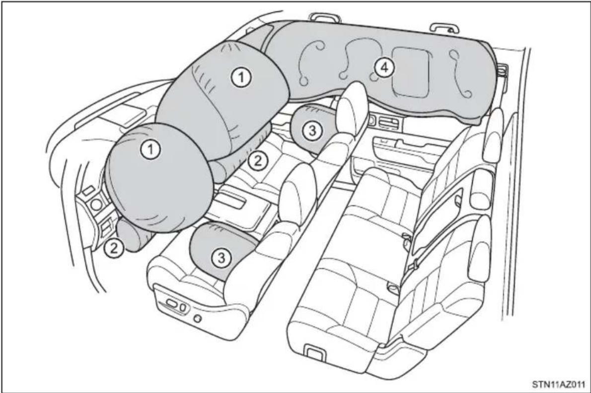
◆ Coussins gonflables SRS frontaux
STS11AZ006
This information has been prepared in accordance with regulation issued by the National Highway Traffic Safety Administration of the U.S. Department of Transportation. It provides the purchasers and/or prospective purchasers of Toyota vehicles with information on truck-camper loading. Your Toyota dealer will help answer any questions you may have as you read this information.
Center of gravity location
The figures given in the illustration indicate the recommended center of gravity zone.
① Recommended location for cargo center of gravity for cargo weight rating
② Rear end of truck bed
▶ Double Cab models with standard bed ▶ Double Cab models with long bed
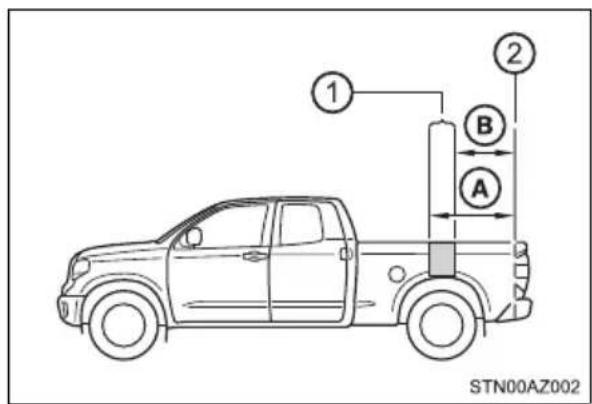
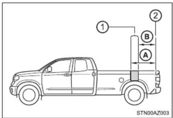
▶ CrewMax models
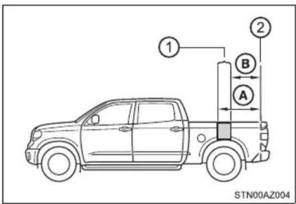
| A | B | |
| Double Cab models | 42.6 in. (1082mm) 37.6 in. (955 mm) | |
| CrewMax models | ||

WARNING
■Loading precaution
If a load is too far back, it can cause dangerous handling. If it is too far forward, the front axle may be overloaded.
Cargo weight rating and proper matching
When the truck is used to carry a slide-in camper, the total cargo load of the truck consists of the manufacturer's camper weight figure, the weight of installed additional camper equipment not included in the manufacturer's camper weight figure, the weight of camper cargo, and the weight of passengers in the camper. The total cargo load should not exceed the truck's cargo weight rating and the camper's center of gravity should fall within the truck's recommended center of gravity zone when installed.
① Camper center of gravity
② Recommended center of gravity location zone
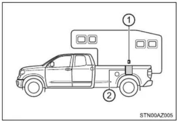
■ Cargo weight rating
| No. | Engine | Drive | Cab | Bed | Grade | Passenger | Cargo Weight Rating | |
| Ibs kg | ||||||||
| 1 | 3UR-FE | 2WD | Double Cab | Standard | SR5 6 | 525 238 | ||
| 2 | Limited | 5 635 288 | ||||||
| 3 | Long SR | R5 6 500 | 227 | |||||
| 4 | 4WD | Standard | SR5 6 | 420 191 | ||||
| 5 | Limited | 5 550 249 | ||||||
| 6 | Long SR | R5 6 390 | 177 | |||||
| 7 | 2WD | Crew Max | Short | SR5 6 | 425 193 | |||
| 8 | Limited | 5 540 245 | ||||||
| 9 | Plati-num | 5 530 240 | ||||||
| 10 | 4WD | SR5 6 | 335 152 | |||||
| 11 | Limited | 5 435 197 | ||||||
| 12 | Plati-num | 5 435 197 | ||||||

WARNING
Overloading
Be careful — overloading can cause dangerous braking and handling problems, and can damage your vehicle and its tires.
Gross axle and vehicle weight ratings
Secure loose items to prevent weight shifts that could affect the balance of your vehicle. When the truck camper is loaded, drive to a scale and weigh on the front and on the rear wheels separately to determine axle loads. Individual axle loads should not exceed either of the Gross Axle Weight Ratings (GAWR). The total of the axle loads should not exceed the Gross Vehicle Weight Rating (GVWR). These ratings are given on the vehicle certification label which is located on the door latch post on the left side of the vehicle. (→P. 541) If weight ratings are exceeded, move or remove items to bring all weights below the ratings.
▶ Gross axle weight rating
① Front GAWR
② Rear GAWR
▶ Gross vehicle weight rating
① Not exceed GVWR
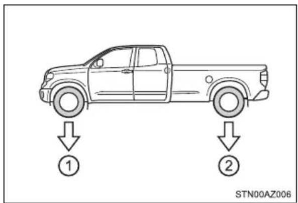
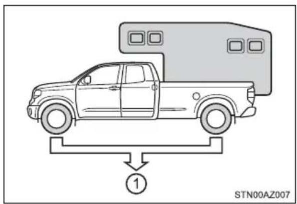
natural_image
Diagram of a pickup truck with a roof-mounted vehicle and a load labeled '1' (no text or symbols on the diagram itself)■ GAWR and GVWR
▶ Double Cab models
| Model code* | Engine | Driving system | Bed type | GAWR | GVWR | |
| Front Rear | ||||||
| USK51L-CRTSKA | 3UR-FE | 2WD | Standard | 3900 lb. (1770 kg) | 4100 lb. (1860 kg) | 6900 lb. (3130 kg) |
| USK51L-CRTLKA | ||||||
| USK52L-CHTSKA | Long | 4150 lb. (1880 kg) | 7000 lb. (3175 kg) | |||
| USK56L-CRTSKA | 4WD | Standard | 4000 lb. (1815 kg) | 7100 lb. (3220 kg) | ||
| USK56L-CRTLKA | ||||||
| USK57L-CHTSKA | Long | 7200 lb. (3265 kg) | ||||
*: The model code is indicated on the Certification Label. (→P. 541)
▶ CrewMax models
| Model code* | Engine | Driving system | Bed type | GAWR | GVWR | |
| Front Rear | ||||||
| USK51L-PSTSKA | 3UR-FE | 2WD | Short | 3900 lb. (1770 kg) | 4150 lb. (1880 kg) | 7000 lb. (3175 kg) |
| USK51L-PSTLKA | ||||||
| USK51L-PSTZKA | ||||||
| USK56L-PSTSKA | 4WD | 4000 lb. (1815 kg) | 7200 lb. (3265 kg) | |||
| USK56L-PSTLKA | ||||||
| USK56L-PSTZKA | ||||||
*: The model code is indicated on the Certification Label. (→P. 541)
Index
What to do if...
(Troubleshooting) 594
Alphabetical index 598
What to do if... (Troubleshooting)
If you have a problem, check the following before contacting your Toyota dealer.
The doors cannot be locked, unlocked, opened or closed

You lose your keys
- If you lose your keys or mechanical keys, new genuine mechanical keys can be made by your Toyota dealer. (→P. 123)
- If you lose your keys or electronic keys, the risk of vehicle theft increases significantly. Contact your Toyota dealer immediately. (→P. 126)

The doors cannot be locked or unlocked
● Is the wireless key battery weak or depleted? (→P. 451)
●Vehicles with a smart key system:
Is the engine switch in ON?
When locking the doors, turn the engine switch off. ( P. 220)
●Vehicles with a smart key system:
Is the electronic key left inside the vehicle?
When locking the doors, make sure that you have the electronic key on your person.
● The function may not operate properly due to the condition of the radio wave. (→P. 123)

The rear door cannot be opened
●Is the child-protector lock set?
The rear door cannot be opened from inside the vehicle when the lock is set. Open the rear door from outside and then unlock the child-protector lock. ( P. 131)
If you think something is wrong

The engine does not start (vehicles without a smart key system)
● Is the shift lever in P? (→P. 217)
● Is the battery discharged? (→P. 525)
The engine does not start (vehicles with a smart key system)
- Did you press the engine switch while firmly depressing the brake pedal? (→P. 219)
● Is the shift lever in P? (→P. 222)
● Is the electronic key anywhere detectable inside the vehicle? (→P. 139)
● Is the steering wheel unlocked? (→P. 222)
●Is the electronic key battery weak or depleted? In this case, the engine can be started in a temporary way. (→P. 523)
● Is the battery discharged? (→P. 525)

The shift lever cannot be shifted from P even if you depress the brake pedal
●Is the engine switch in ON? If you cannot release the shift lever by depressing the brake pedal with the engine switch in ON. (→P. 229)

The steering wheel cannot be turned after the engine is stopped
●Vehicles without a smart key system:
It is locked to prevent theft of the vehicle if the key is removed from the engine switch. (→P. 218)
●Vehicles with a smart key system:
It is locked automatically to prevent theft of the vehicle. (→P. 222)
The windows do not open or close by operating the power window switches
- Is the window lock switch pressed? The power window except for the one at the driver's seat cannot be operated if the window lock switch is pressed. (→P. 172)
The engine switch is turned off automatically (vehicles with a smart key system)
● The auto power off function will be operated if the vehicle is left in ACC or ON (the engine is not running) for a period of time. (→P. 221)

A warning buzzer sounds during driving
●The seat belt reminder light is flashing
Are the driver and the front passenger wearing the seat belts? (→P. 486)
●The parking brake indicator is on Is the parking brake released? (→P. 233)
Depending on the situation, other types of warning buzzer may also sound. ( P. 485, 493)

A warning buzzer sounds when leaving the vehicle (vehicles with a smart key system)
●Is the electronic key left inside the vehicle?
Check the message on the multi-information display. ( P. 493)

An alarm is activated and the horn sounds
● Did anyone inside the vehicle open a door during setting the alarm?
The sensor detects it and the alarm sounds. ( P. 95)
To stop the alarm, turn the engine switch to ACC or ON, or start the engine.

A warning light turns on or a warning message or indicator is displayed
- When a warning light turns on or a warning message is displayed, refer to P. 485, 493.
When a problem has occurred

If you have a flat tire
- Stop the vehicle in a safe place and replace the flat tire with the spare tire. (→P. 506)
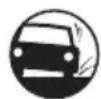
The vehicle becomes stuck
● Try the procedure for when the vehicle becomes stuck in mud, dirt, or snow. (→P. 532)
Alphabetical index
A
A/C 340,347
Air conditioning filter 448
Automatic air conditioning system.... 347
Manual air conditioning system.... 340
ABS (Anti-lock Brake
System) 320
Function 320
Warning light.... 486
Air conditioning filter 448
Air conditioning
system.... 340, 347
Air conditioning filter 448
Automatic air conditioning system.... 347
Manual air conditioning system.... 340
Airbags 40
Airbag operating conditions ....49
Airbag precautions for your child.... 44
Airbag warning light 485
Correct driving posture ..... 32
Curtain shield airbag operating conditions .... 49
Curtain shield airbag precautions.... 45
Front passenger occupant classification system.... 53
General airbag precautions .... 44
Locations of airbags...... 40
Modification and disposal of airbags 47
Side airbag operating conditions 49
Side airbag precautions..... 45
Side and curtain shield airbags operating conditions .... 49
Side and curtain shield airbags precautions...... 45
SRS airbags 40
Alarm
Alarm 95
Warning buzzer 485, 493
Anchor brackets.... 63
Antennas
(smart key system) 138
Anti-lock Brake System
(ABS) 320
Function.... 320
Warning light.... 486
Armrest.... 383
Assist grips.... 384
Audio input*
Audio remote control switches ^ AUX port ^
AUTO LSD system...... 318
Automatic High Beam 239
Automatic light control system.... 234
Automatic transmission
Automatic transmission ..... 225
If the shift lever cannot be shifted from P.... 229
TOW/HAUL switch.... 228
AUX port*
Auxiliary boxes.... 373
B
Back window
Back window.... 175
Power back window 176
Back-up lights
Replacing light bulbs...... 468
Wattage 550
Battery 422
If the vehicle battery is discharged.... 525
Preparing and checking before winter.... 331
Warning light.... 485
Blind Spot Monitor (BSM) ..... 305
Bluetooth®\*
Bottle holders 372
Brake
Fluid 420
Parking brake.... 233
Warning buzzer...... 485
Warning light.... 485
Brake assist 320
Brake Override System...... 185
Break-in tips.... 186
Brightness control
Instrument panel light control.... 107
BSM (Blind Spot Monitor) ..... 305
Blind Spot Monitor function.... 309
Rear Cross Traffic Alert function.... 312
C
Camper information 588
Card holder 364
Care 400, 403
Aluminum wheels 400
Exterior 400
Interior 403
Seat belts.... 404
Cargo capacity.... 195
Cargo lamp
Light switch.... 359
Replacing light bulbs .... 470
Wattage 550
CD player\*
Certification label ...... 200, 541
Chains 332
Child restraint system.... 59
Booster seats, definition ..... 60
Booster seats, installation..... 69
Convertible seats, definition ... 60
Convertible seats, installation 68
Front passenger occupant classification system .... 53
Infant seats, definition...... 60
Infant seats, installation ..... 67
Installing CRS with LATCH anchors .... 65
Installing CRS with seat belts.... 67
Installing CRS with top tether strap..... 70, 73
Child safety 58
Airbag precautions...... 44
Battery precautions...... 527
Child restraint system .... 59
How your child should wear the seat belt .... 36
Installing child restraints ..... 63
Moon roof precautions......182
Power back window precautions.... 178
Power window lock switch .... 172
Power window precautions... 174
Rear door child-protector.....131
Removed wireless remote control battery precautions.... 453
Seat belt extender precautions.... 39
Seat belt precautions...... 62
Seat heater precautions...... 355
Child-protectors...... 131
Cleaning 400, 403
Aluminum wheels.... 400
Exterior 400
Interior...... 403
Seat belts.... 404
Clock\*
Compass 394
Condenser...... 420
Console box 363
Coolant 418
Capacity.... 545
Checking.... 418
Preparing and checking before winter.... 331
Cooling system...... 418
Engine overheating.... 529
CRS 59
Cruise control
Cruise control 294
Dynamic radar cruise control.... 280
Cup holders 370
Curtain shield airbags...... 41
Customizable features ..... 564
D
Daytime running light
system.... 237
Deck hooks 377
Defogger
Back window.... 342, 349
Outside rear view mirrors 342, 349
Windshield 342, 349
Differential.... 546
Dimensions 536
Dinghy towing.... 216
Display
Drive information 111
Dynamic radar cruise control.... 280
LDA (Lane Departure Alert) ...... 272
Multi-information display...... 110
Trip information.... 110
Warning message.... 493
Do-it-yourself maintenance .... 412
Door lock.... 127
Doors.... 127
Key 127
Smart key system 128
Wireless remote control..... 128
Doors 127
Automatic door locking and unlocking system...... 132
Door glasses.... 172
Door lock.... 130
Open door warning message.... 494
Outside rear view mirrors..... 167
Rear door child-protector..... 131
Side doors.... 127
Driver's seat position
memory 152
Drive-Start Control 185
Driving 184
Break-in tips.... 186
Correct driving posture ..... 32
Driving assist system...... 320
Procedures 184
Winter drive tips 331
Dynamic radar
cruise control 280
Constant speed control mode...... 285
Vehicle-to-vehicle distance control mode ..... 287
E
EDR (Event data recorder)...... 11
Emergency, in case of
If the engine will not start..... 521
If the vehicle is trapped in rising water...... 477
If the vehicle has discharged battery 525
If the warning buzzer sounds.... 485
If the warning light turns on 485
If the warning message is displayed 493
If you have a flat tire 506
If you lose your keys...... 123
If you think something is wrong.... 483
If your vehicle becomes stuck.... 532
If your vehicle has to be stopped in an emergency... 475
If your vehicle needs to be towed.... 478
If your vehicle overheats..... 529
Emergency flashers 474
Engine
"ACC" position 217
Compartment...... 415
Engine switch 217
Hood.... 414
How to start the engine...... 217
Identification number 541
If the engine will not start..... 521
Ignition switch (engine switch)...... 217
Immobilizer system.... 85
Overheating.... 529
Engine coolant...... 418
Capacity.... 545
Checking.... 418
Preparing and checking before winter.... 331
Engine coolant temperature gauge.... 105
Engine immobilizer system ..... 85
Engine oil 416
Capacity.... 543
Checking.... 416
Preparing and checking before winter.... 331
Engine oil maintenance data.... 407
Engine switch (ignition switch)...... 217
Engine switch light (ignition switch light) ...... 357
Event data recorder (EDR)...... 11
F
Flat tire 506
Floor mats 30
Fluid
Automatic transmission ..... 546
Brake 547
Washer 425
Fog lights 244
Replacing light bulbs 466
Switch.... 244
Wattage 550
Foot well light 357
Four-wheel drive system ..... 315
Front passenger occupant classification system.... 53
Front personal lights...... 358
Front seats 147
Adjustment...... 147
Cleaning 403
Correct driving posture ..... 32
Driving position memory..... 152
Head restraints 157
Power easy access system.... 152
Seat heaters 354
Seat position memory...... 152
Seat ventilators.... 354
Front side marker lights
Light switch.... 234
Replacing light bulbs 464
Wattage 550
Front turn signal lights
Replacing light bulbs ..... 463
Turn signal lever.... 232
Wattage 550
Fuel 542
Capacity.... 542
Fuel gauge.... 105
Fuel pump shut off system ... 484
Gas station information...... 612
Information...... 551
Refueling 248
Type.... 248, 542
Warning light.... 486
Warning message...... 495
Fuel consumption
Average fuel consumption 117
Current fuel consumption..... 117
Fuel filler door.... 250
Fuel pump shut off system..... 484
Fuses 454
G
Gas station information ...... 612
Gauges 105
Glove box 362
H
Hands-free system
(for cellular phone)*
Head restraints 157
Headlights 234
Automatic High Beam 239
Light switch 234
Replacing light bulbs.... 459
Wattage 550
Heaters
Automatic air conditioning system.... 347
Manual air conditioning system.... 340
Outside rear view mirrors 342, 349
Seat heaters ....354
High mounted stoplight
Replacing...... 470
Wattage 550
Hood 414
Hooks
Deck hooks.... 377
Retaining hooks (floor mat) .... 30
Horn 162
|
I/M test 411
Identification
Engine 541
Tire 555
Vehicle.... 541
Ignition switch
(engine switch)...... 217
Ignition switch light
(engine switch light) 357
Illuminated entry system ..... 359
Immobilizer system...... 85
Indicators 102
Initialization
Maintenance.... 407
Moon roof 181
Tire pressure warning system .... 428
Inside rear view mirror...... 164
Instrument panel light
control.... 107
Interior lights 357
Personal lights.... 358
Switches 357
Wattage 550
Intuitive parking assist ...... 298
Function...... 298
Warning message...... 494, 495
J
Jack
Positioning the jack.... 513
Vehicle-equipped jack......507
Jack handle.... 511
Jam protection function
Moon roof.... 179
Power windows....173
K
Keyless entry 128
Smart key system 128
Wireless remote control..... 128
Keys 120
Engine switch...... 217
If you lose your keys...... 123
Ignition switch 217
Key number plate.... 120
Keyless entry 128
Replacing the battery...... 451
Wireless remote control..... 128
Knee airbags 41
L
Lane Departure Alert
(LDA) 272
Language
(multi-information display)... 110
LATCH anchors 65, 66
LDA
(Lane Departure Alert) ...... 272
Lane departure alert function.... 272
Vehicle sway warning ..... 273
Lever
Auxiliary catch lever...... 414
Hood lock release lever ..... 414
Shift lever.... 225
Turn signal lever 232
Wiper lever.... 245
License plate lights
Light switch.... 234
Replacing light bulbs ..... 469
Wattage 550
Light bulbs
Replacing...... 459
Wattage 550
Lights
Automatic High Beam...... 239
Cargo lamp switch.... 359
Engine switch light (ignition switch light)...... 357
Fog light switch.... 244
Headlight switch 234
Illuminated entry system...... 359
Interior lights.... 358
Interior lights list.... 357
Outer foot light.... 357
Personal lights.... 358
Replacing light bulbs ..... 457
Turn signal lever.... 232
Vanity lights 378
Wattage 550
Load capacity 195
Luggage compartment
features 377
Luggage storage box 375
M
Maintenance
Do-it-yourself maintenance... 412
General maintenance .....408
Maintenance data 536
Maintenance requirements ... 406
Resetting the message indicating maintenance is required ....407
Malfunction indicator lamp..... 485
Manual headlight leveling dial 236
Map holder 366
Master warning light..... 486, 493
Meter
Indicators 102
Instrument panel light control.... 107
Meters.... 105
Multi-information display...... 110
Warning lights....101
Mirrors
Inside rear view mirror ..... 164
Outside rear view mirror defoggers..... 342, 349
Outside rear view mirrors..... 167
Vanity mirrors.... 378
Moon roof 179
Door lock linked moon roof operation .... 180
Jam protection function...... 179
Operation 179
MP3 disc\*
Multi-information display...... 110
Customizing vehicle features .... 564
Drive information 111
Dynamic radar cruise control.... 280
LDA (Lane Departure Alert) ..... 272
Settings.... 114
Trip information...... 110
Warning message.... 493
N
Noise from under vehicle ...... 8
O
Odometer 105, 107
Off-road precautions...... 335
Oil
Engine oil.... 543
Differential oil.... 546
Transfer oil.... 547
Opener
Hood.... 414
Outer foot lights
Location 357
Replacing light bulbs 470
Wattage 550
Outside rear view mirrors...... 167
Adjusting and folding ..... 167
Blind spot monitor.... 305
Mirror position memory...... 152
Outside rear view mirror defoggers..... 342, 349
Outside temperature
display.... 105
Overhead console 369
Overheating 529
P
Parking assist sensors
(intuitive parking assist)...... 298
Parking brake.... 233
Operation 233
Parking brake engaged warning buzzer 485
Parking brake engaged warning message .... 495
Parking lights.... 234
Light switch 234
Replacing light bulbs.....463, 470
Wattage 550
PCS
(Pre-Collision System)...... 260
Pre-collision brake assist.....261
Pre-collision braking 261
PCS warning...... 261
Warning light.... 488
Warning message...... 493
Pen holder.... 367
Personal lights.... 358
Light switch 357
Wattage 550
Power back window 176
Power easy access system .... 152
Power outlets...... 379
Power steering fluid 421
Power windows.... 172
Jam protection function...... 173
Operation 172
Window lock switch.... 172
Pre-Collision System
(PCS) 260
R
Radar cruise control
(dynamic radar cruise control).... 280
Radiator...... 420
Radio\*
Rear personal lights...... 358
Rear seat
Adjustment precautions..... 151
Child seats/child restraint system installation.... 63
Cleaning 403
Head restraints 157
Raising the bottom cushion.... 150
Rear side marker lights...... 234
Light switch.... 234
Replacing light bulbs 468
Wattage 550
Rear step bumper.... 137
Rear turn signal lights ...... 232
Replacing light bulbs ..... 468
Turn signal lever.... 232
Wattage 550
Rear view mirror
Inside rear view mirror...... 164
Outside rear view mirrors ..... 167
Rear view monitor system\*
Refueling 248
Capacity.... 542
Fuel types 542
Opening the fuel tank cap..... 250
Replacing
Fuses.... 454
Light bulbs 457
Tires.... 506
Wireless remote control battery 451
Reporting safety defects
for U.S. owners...... 576
Resetting the message
indicating maintenance is required.... 407
\$
Safety connect 79
Seat belts.... 34
Adjusting the seat belt 35
Automatic Locking Retractor.... 36
Child restraint system installation 63
Cleaning and maintaining the seat belt.... 404
Emergency Locking Retractor.... 36
How to wear your seat belt ..... 34
How your child should wear the seat belt.... 36
Pregnant women, proper seat belt use.... 37
Reminder light and buzzer.... 486
Seat belt extender.... 36
Seat belt pretensioners...... 35
SRS warning light 485
Seat heaters 354
Seat position memory...... 152
Seat ventilators.... 354
Seating capacity 195
Seats, Front...... 147
Adjustment...... 147
Adjustment precautions .....149
Child seats/child restraint system installation.... 63
Cleaning....403
Driving position memory ..... 152
Head restraints 157
Power easy access system.... 152
Properly sitting in the seat ..... 32
Seat heaters 354
Seat position memory...... 152
Seat ventilators.... 354
Seats, Rear.... 150
Adjustment precautions...... 151
Child seats/child restraint system installation...... 63
Cleaning 403
Head restraints 157
Raising the bottom cushion.... 150
Sensor
Automatic headlight system.... 237
Automatic High Beam system.... 239
Inside rear view mirror ..... 166
Intuitive parking assist ..... 298
LDA (Lane Departure Alert) ..... 272
Radar sensor.... 253
Service reminder indicators... 100
Shift lever 225
Automatic transmission ..... 225
If the shift lever cannot be shifted from P .... 229
Shift lock system.... 229
Side airbags 41
Side doors.... 127
Side marker lights 234
Light switch.... 234
Replacing light bulbs .... 464, 468
Wattage 550
Side mirrors 167
Adjusting and folding ..... 167
BSM (Blind spot monitor)..... 305
Mirror position memory...... 152
Side turn signal lights...... 232
Replacing light bulbs .... 464, 468
Turn signal lever.... 232
Wattage 550
Smart key system 138
Antenna location.... 138
Entry functions.... 128
Starting the engine....217
Warning message.... 502
Snow tires 333
Spare tire 506
Inflation pressure 548
Replacing.... 506
Storage location.... 507
Spark plug 545
Specifications 536
Speedometer.... 105
Steering
Column lock release ...... 218
Steering wheel
Adjustment...... 161, 162
Steering wheel position memory .... 152
Steering wheel audio switches\*
Stop lights
Replacing light bulbs......468
Wattage 550
Storage box.... 375
Storage feature 360
Stuck
If the vehicle becomes stuck.... 532
Sunvisors 378
Switches
Automatic High Beam...... 239
Back window defogger switch 342, 349
BSM (Blind spot monitor) main switch 305
Cargo lamp main switch ..... 359
Cruise control switch ..... 294
Door lock switch 130
Driving position memory switches 152
Dynamic radar cruise control switch 280
Emergency flashers switch... 474
Engine switch 217
Fog light switch.... 244
Front-wheel drive control switch 315
Garage door opener switches .... 385
Ignition switch.... 217
Intuitive parking assist ..... 298
LDA (Lane Departure Alert) switch 272
Light switches 234
Moon roof switches...... 179
Outside rear view mirror defoggers switch ..... 342, 349
Outside rear view mirror switches.... 167
Personal/interior lights main switch.... 357
Power back window switch .... 176
Power door lock switch...... 130
Power window switches...... 172
Seat heater switches ..... 354
Seat ventilator switches.....354
Tilt and telescopic steering control switch..... 162
Tire pressure warning reset switch 428
TOW/HAUL switch...... 228
Turn signal lights.... 232
VSC off switch 318, 323
Window lock switch.... 172
Windshield wiper de-icer switch .... 343, 350
Windshield wipers and washer switch...... 245
T
Tachometer 105
Tail lights.... 234
Light switch.... 234
Replacing light bulbs .... 468
Wattage 550
Tailgate
Removing the tailgate...... 134
Tailgate.... 133
Talk switch*
Telephone switches*
Theft deterrent system
Alarm 95
Engine immobilizer system..... 85
Tire inflation pressure...... 442
Maintenance data 548
Warning light.... 487
Tire information 554
Glossary 559
Size.... 555
Tire identification number ..... 555
Uniform Tire Quality Grading 557
Tire pressure warning
system...... 427
Initializing...... 428
Installing tire pressure warning valves and transmitters .... 427
Registering ID codes ...... 429
Tire pressure warning reset switch 428
Warning light.... 487
Tires 426
Chains.... 332
Checking.... 426
If you have a flat tire 506
Inflation pressure 548
Information...... 554
Replacing.... 506
Rotating tires.... 426
Size.... 548
Snow tires 333
Spare tire 507
Tire pressure warning system.... 427
Warning light 487
Tissue pocket...... 368
Tools 507
Top tether strap 70, 73
Total load capacity ..... 195, 538
TOW/HAUL switch 228
Towing
Bumper towing.... 207
Dinghy towing 216
Emergency towing 481
Fifth wheel trailer 206
Trailer brake controller...... 327
Trailer towing 197
TRAC (Traction Control) ...... 320
Toyota Safety Sense P...... 252
Automatic High Beam 239
Dynamic radar cruise control.... 280
LDA
(Lane Departure Alert)...... 272
PCS
(Pre-Collision System)...... 260
Trailer brake controller .... 327
Transmission 225
Automatic transmission...... 225
If the shift lever cannot be shifted from P 229
S mode 227
Trip meters.... 105, 107
Turn signal lights 232
Replacing light bulbs..... 463, 468, 470
Turn signal lever.... 232
Wattage 550
U
USB charging ports...... 382
USB port*
V
Vanity lights
Vanity lights 378
Wattage 550
Vanity mirrors 378
Vehicle data recording...... 9
Vehicle identification number.... 541
Vehicle Stability Control (VSC) 320
Ventilators (seat ventilators) 354
Voice command system*
VSC
(Vehicle Stability Control) .... 320
W
Warning buzzers
Brake system.... 485, 495
Downshifting 231
Intuitive parking assist ..... 299
Key reminder 218
Light reminder.... 238
Open door.... 494
Open moon roof.... 181
PCS
(Pre-Collision System)...... 488
Seat belt reminder 486
Warning lights.... 101
ABS.... 486
Brake system...... 485
Charging system...... 485
LDA
(Lane Departure Alert)...... 488
Low fuel level.... 486
Malfunction indicator lamp.... 485
Master warning light...... 486
Parking brake warning light 486
PCS
(Pre-Collision System)...... 488
Seat belt reminder light..... 486
Slip indicator 487
SRS 485
Tire pressure.... 487
Warning messages...... 493
Washer.... 245
Checking.... 425
Low windshield washer fluid warning message 495
Preparing and checking before winter.... 331
Switch 245
Washing and waxing...... 400
Weight
Cargo capacity.... 195
Cargo weight rating 590
Gross axle weight rating..... 592
Gross combination weight rating.... 201
Gross vehicle weight rating 592
Load limits 195
Towing capacity...... 195, 201
Trailer Weight Rating.... 195, 201
TWR 195,201
Vehicle capacity weight.... 195, 538
Wheels
Replacing wheels 446
Size.... 548
Window glasses 172
Window lock switch 172
Windows.... 172
Back window.... 175
Back window defogger 342, 349
Power back window...... 176
Power windows.... 172
Windshield wiper
de-icer 343, 350
Windshield wipers...... 245
Winter driving tips.... 331
Wireless remote control key
Locking/Unlocking 128
Replacing the battery...... 451
WMA disc\*
GAS STATION INFORMATION
Auxiliary catch lever Fuel filler door
P. 414 P. 250
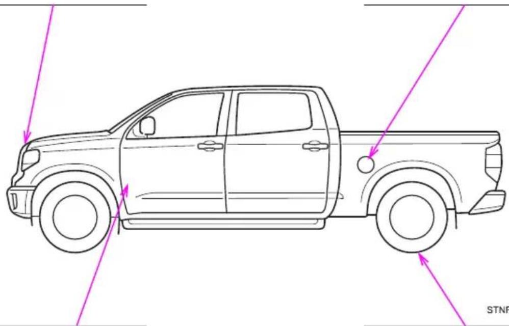
natural_image
Side profile line drawing of a pickup truck showing front and side views with directional arrows (no text or symbols)Hood lock release lever
P. 414
Tire inflation pressure
P. 548
| Fuel tank capacity(Reference) | Standard fuel tank:26.4 gal. (100.0 L, 22.0 Imp.gal.)Large fuel tank:38.0 gal. (144.0 L, 31.7 Imp.gal.) |
| Fuel type P. 542 | |
| Cold tire inflation pressure P. 548 | |
| Engine oil capacity(Drain and refill — reference) | qt. (L, Imp.qt.)With filter 8.5 (8.0, 7.0)Without filter 7.9 (7.5, 6.6) |
| Engine oil type P. 543 | |
- For safety and security
- 1-1. For safe use
- 1-2. Emergency assistance
- 1-3. Theft deterrent system
- Instrument cluster
- Instrument cluster
- Operation of each component
- 3-1. Key information
- 3-2. Opening, closing and locking the doors
- 3-3. Adjusting the seats
- 3-4. Adjusting the steering wheel and mirrors
- 3-5. Opening, closing the windows and moon roof
- Driving
- 4-1. Before driving
- 4-2. Driving procedures
- 4-3. Operating the lights and wipers
- 4-4. Refueling
- 4-5. Using the driving support systems
- 4-6. Driving tips
- Interior features
- 5-1. Using the air conditioning system
- 5-2. Using the interior lights
- 5-3. Using the storage features
- 5-4. Using the other interior features
- Maintenance and care
- 6-1. Maintenance and care
- 6-2. Maintenance
- 6-3. Do-it-yourself maintenance
- When trouble arises
- 7-1. Essential information
- 7-2. Steps to take in an emergency
- Vehicle specifications
- 8-1. Specifications
- 8-2. Customization
- 8-3. Items to initialize
- For owners
- Index
- For your information
- Main Owner's Manual
- Noise from under vehicle after turning off the engine
- Accessories, spare parts and modification of your Toyota
- Installation of a mobile two-way radio system
- Vehicle data recording
- ●Data usage
- Usage of data collected through Safety Connect (U.S.mainland only)
- Event data recorder
- Scrapping of your Toyota
- Perchlorate Material
- WARNING
- ■General precautions while driving
- ■General precaution regarding children's safety
- Reading this manual
- WARNING:
- NOTICE:
- How to search
- ■Searching by name
- ■Searching by installation position
- ■Searching by symptom or sound
- ■Searching by title
- Pictorial index
- Exterior
- Light bulbs of the exterior lights for driving
- Instrument panel
- Front separated type seats
- ▶ Front bench type seat
- Switches
- Interior
- Front bench type seat
- For safety and security
- 1
- Before driving
- Floor mat
- When installing the driver's floor mat
- For safe driving
- Correct driving posture
- Correct use of the seat belts
- Adjusting the mirrors
- Seat belts
- Fastening and releasing the seat belt
- Adjusting the seat belt shoulder anchor height
- Seat belt pretensioners (front seats)
- Emergency locking retractor (ELR)
- ■Automatic locking retractor (ALR)
- ■Child seat belt usage
- ■Replacing the belt after the pretensioner has been activated
- ■Seat belt extender
- ■Wearing a seat belt
- ■ Pregnant women
- ■People suffering illness
- ■When children are in the vehicle
- ■Seat belt pretensioners
- ■Adjustable shoulder anchor
- ■Seat belt damage and wear
- ■ Using a seat belt extender
- NOTICE
- ■When using a seat belt extender
- SRS airbags
- ◆ SRS front airbags
- ◆ SRS side and curtain shield airbags
- SRS airbag system components
- ■SRS airbag precautions
- ■Modification and disposal of SRS airbag system components
- ■If the SRS airbags deploy (inflate)
- ■ SRS airbag deployment conditions (SRS front airbags)
- ■ SRS airbag deployment conditions (SRS side and curtain shield airbags)
- ■ Conditions under which the SRS airbags may deploy (inflate), other than a collision
- ■ Types of collisions that may not deploy the SRS airbags (SRS front airbags)
- ■Types of collisions that may not deploy the SRS airbags (SRS side and curtain shield airbags)
- ■When to contact your Toyota dealer
- Front passenger occupant classification system
- Condition and operation in the front passenger occupant classification system
- ■Front passenger occupant classification system precautions
- Safety information for children
- Child restraint systems
- Points to remember
- Types of child restraints
- ■Selecting an appropriate child restraint system
- ■Child restraint precautions
- ■When the child restraint system is not in use
- Installing child restraints
- When installing in the rear outboard seats (Double Cab models)
- When installing in the rear outboard seats (CrewMax models)
- Installing child restraints using a seat belt (child restraint lock function belt)
- ■ Rear-facing — Infant seat/convertible seat
- ■ Forward-facing — Convertible seat
- ■ Booster seat
- Removing a child restraint installed with a seat belt
- Child restraint systems with a top tether strap (Double Cab models)
- ■Right rear seat or center rear seat
- ■ Left rear seat
- Child restraint systems with a top tether strap (CrewMax models)
- ■Left seat
- ■Laws and regulations pertaining to anchorages
- ■When installing a booster seat
- ■When installing a child restraint system
- ■ Do not use a seat belt extender
- ■To correctly attach a child restraint system to the anchors
- Exhaust gas precautions
- ■ Important points while driving
- When parking
- Exhaust pipe
- Safety Connect\*
- ■System components
- Services
- Subscription
- ■Safety Connect Services Information
- Languages
- ■When contacting the response center
- Safety Connect LED light Indicators
- ■Automatic Collision Notification
- ■Stolen Vehicle Location
- Emergency Assistance Button ("SOS")
- ■Enhanced Roadside Assistance
- Safety information for Safety Connect
- ■Exposure to radio frequency signals
- ■Certification for Safety Connect
- FCC/IC WARNING:
- FCC/IC AVERTISSEMENT:
- Engine immobilizer system
- System maintenance
- ■Conditions that may cause the system to malfunction
- ■Certifications for the engine immobilizer system
- ■Certifications for the immobilizer system
- ■To ensure the system operates correctly
- Alarm\*
- The alarm
- Setting the alarm system
- Deactivating or stopping the alarm
- Items to check before locking the vehicle
- ■Triggering of the alarm
- ■Alarm-operated door lock
- Instrument cluster
- 2
- Warning lights and indicators
- Warning lights
- Indicators
- If a safety system warning light does not come on
- Gauges and meters
- Changing the odometer/trip meter display
- Odometer
- ■Trip meter A\*/trip meter B\*
- Instrument panel light control
- ■The multi-information display illuminate when
- ■The brightness of the instrument panel lights
- ■ Outside temperature display
- Liquid crystal display
- ■The information display at low temperatures
- ■To prevent damage to the engine and its components
- Voltmeter
- ■Engine oil pressure gauge
- Multi-information display
- Display contents
- ●Menu icons
- Warning message display
- Settings display
- ■ Operating the meter control switches
- Drive information
- ●Current
- ●Average Speed\*/Trip Average Speed
- ●Total Time \*/Trip Time
- ●Trip distance
- ●Digital speedometer
- ●Display off
- \*: Resetting procedures:
- ●LDA (Lane Departure Alert) *1 ( → P. 567)
- ●PCS (Pre-Collision System) * 1 ( → P. 567)
- ●Meter setting
- Setting items
- ■Pop-up display
- ■When disconnecting and reconnecting battery terminals
- ■Trip summary display
- ■Tire inflation pressure
- ■Caution for use while driving
- ■Cautions during setting up the display
- During setting up the display
- Fuel consumption information\*
- Display the trip information or past record screen
- Fuel consumption
- ■Trip information
- Past record
- ■ Resetting the data
- ■ Updating the past record data
- Cruising range
- Operation of each component
- 3
- Keys
- The keys
- ▶ Type A
- ▶ Type B
- ▶ Type C
- Wireless remote control (type B or type C)
- Using the mechanical key (type C)
- ■Panic mode (type B or type C)
- - When required to leave the vehicle's key with a parking attendant (type C)
- If you lose your keys
- ■When riding in an aircraft (type B or type C)
- ■Conditions affecting operation (type B or type C)
- ■Key battery depletion (type B or type C)
- ■Replacing the battery (type B or type C)
- ■ Confirmation of the registered key number
- ■ Customization (type B or type C)
- ■Certification for wireless remote control (type B)
- NOTE:
- FCC WARNING:
- ■Certification for wireless remote control (type C)
- ■To prevent key damage
- - Carrying the electronic key on your person (type C)
- In case of a smart key system malfunction or other key-related problems (type C)
- ■When an electronic key is lost (type C)
- Side doors
- Unlocking and locking the doors from the outside
- Key
- ◆ Wireless remote control (if equipped)
- Smart key system (if equipped)
- Unlocking and locking the doors from the inside
- ■Door lock switch
- Driver's door lock switch
- ▶ Passenger's door lock switch
- ■Inside lock buttons
- Locking the front doors from the outside without a key
- Rear door child-protector lock
- Automatic door locking and unlocking systems
- ■ Customization that can be configured at Toyota dealer
- Tailgate
- Locking/unlocking the tailgate
- Opening/closing the tailgate
- Removing the tailgate
- ■Before removing the tailgate
- ■Removing the tailgate
- Rear step bumper
- ■Caution while driving
- ■To prevent damage to the tailgate wire harness
- ■To prevent damage to the camera lens
- ■After closing the tailgate
- ■To prevent damage to the rear step bumper
- Smart key system\*
- Antenna location
- ■ Effective range (areas within which the electronic key is detected)
- ■Alarms and warning indicators
- ■Battery-saving function
- Electronic Key Battery-Saving Function
- ■Conditions affecting operation
- ■Note for the entry function
- ■Note for the unlocking function
- ■When the vehicle is not driven for extended periods
- ■To operate the system properly
- If the smart key system does not operate properly
- Customization
- If the smart key system has been deactivated in a customized setting
- ■Certification for the smart key system
- ■Caution regarding interference with electronic devices
- Front seats
- Adjustment procedure (separated type seats)
- Driver's seat
- ■Passenger's seat
- Power seat
- Adjustment procedure (bench type seats)
- ■ Power easy access system (vehicles with driving position memory)
- ■When adjusting the seat position
- Seat adjustment
- ■When adjusting the seat positions
- Rear seats
- Raising the bottom cushion
- ■When raising the bottom cushion
- ■When bottom cushion is raised
- ■When returning the seats to their original position
- ■Before raising the bottom cushion
- Driving position memory (driver's seat)\*
- Power easy access system
- Operation of the power easy access system
- Driving position memory
- ■Recording procedure
- ■ Recall procedure
- ■To stop the position recall operation part-way through
- ■ Seat positions that can be memorized ( → P. 147)
- - Operating the driving position memory after the key is removed from the engine switch
- In order to correctly use the driving position memory function
- Memory recall function
- ■Registering procedure
- ■Cancelation procedure
- If the battery is disconnected
- ■Seat adjustment caution
- Head restraints
- ■ Center seat
- ■Outer seat
- ① Touse
- ② To fold
- ■Removing the head restraints
- ■Installing the head restraints
- ■Adjusting the height of the head restraints (front seats)
- ■ Adjusting the front center seat (bench type seat) and rear center seat head restraints
- ■Head restraint precautions
- Steering wheel
- Adjustment procedure (manually adjustable type)
- Adjustment procedure (power-adjustable type)
- Horn
- ■After adjusting the steering wheel (manual adjustable type)
- Auto tilt away (power-adjustable type)
- Inside rear view mirror
- Adjusting the height of rear view mirror
- Anti-glare function
- ON/OFF
- Outside rear view mirrors
- Adjustment procedure
- ▶ Manually adjustable type
- ▶ Power-adjustable type (type A)
- Folding the mirrors
- Extending the mirrors (if equipped)
- Linked mirror function when reversing (if equipped)
- ■Adjusting the mirror angle when the vehicle is reversing
- ■When a mirror is moving (power-adjustable type)
- ■ When the mirror defoggers are operating (vehicles with outside rear view mirror defoggers)
- Power windows
- Opening and closing procedures
- Window lock switch
- ■The power windows can be operated when
- - Operating the power windows after turning the engine off
- ■Jam protection function (type B only)
- ■When the power window does not close normally (type B only)
- ■Closing the windows
- Back window\*
- Opening and closing
- Open/close
- ■ Closing the back window
- Power back window\*
- ▶ Double Cab models
- Moon roof\*
- Tilting up and down
- ■The moon roof can be operated when
- ■Operating the moon roof after turning the engine off
- Jam protection function
- Sunshade
- ■Door lock linked moon roof operation
- ■When the moon roof does not close normally
- ■Moon roof open reminder function
- ■When the battery is disconnected
- ■ Opening the moon roof
- ■ Closing the moon roof
- Driving
- 4
- Driving the vehicle
- Starting the engine
- Stopping
- Parking the vehicle
- Starting off on a steep uphill
- - Driving in the rain
- ■Engine speed while driving
- ■Restraining the engine output (Brake Override System)
- ■Restraining sudden start (Drive-Start Control)
- ■Breaking in your new Toyota
- ■Drum-in-disc type parking brake system
- ■Operating your vehicle in a foreign country
- ■When turning off the engine
- ■When starting the vehicle
- ■When driving the vehicle
- ■When driving on slippery road surfaces
- ■When shifting the shift lever
- If you hear a squealing or scraping noise (brake pad wear limit indicators)
- ■When the vehicle is stopped
- ■When the vehicle is parked
- ■When taking a nap in the vehicle
- When braking
- ■When parking the vehicle
- ■Avoiding damage to vehicle parts
- If you get a flat tire while driving
- ■When encountering flooded roads
- Cargo and luggage
- Capacity and distribution
- Steps for Determining Correct Load Limit —
- Calculation formula for your vehicle
- ■Things that must not be carried in the luggage compartment
- ■Storage precautions
- ■Capacity and distribution
- Vehicle load limits
- ■Overloading the vehicle
- Trailer towing
- Towing related terms
- ■GCWR (Gross Combination Weight Rating)
- ■GVWR (Gross Vehicle Weight Rating)
- ■ GAWR (Gross Axle Weight Rating)
- ■TWR (Trailer Weight Rating)
- ■ Unbraked TWR (Unbraked Trailer Weight Rating)
- ■Tongue Weight
- Kingpin Weight
- Weight limits
- GCWR, TWR, Unbraked TWR, Fifth wheel and Gooseneck towing TWR
- ■GCWR *5 and TWR *5
- Trailer Tongue Weight and Trailer Kingpin Weight
- Conventional Towing
- 2.Fifth wheel Towing or Gooseneck Towing
- Hitch
- Bumper towing (vehicles with steel bumper only)
- Selecting trailer ball
- Positions for towing hitch receiver
- Connecting trailer lights
- Trailer towing tips
- ■Trailer brake controller
- ■ Matching trailer ball height to trailer coupler height
- Before towing
- ■Break-in schedule
- Maintenance
- If trailer sway occurs
- ■Trailer towing precautions
- ■To avoid accident or injury
- ■When towing a trailer
- ■When installing a trailer hitch
- ■Do not directly splice trailer lights
- ■When towing a fifth wheel trailer
- Dinghy towing
- ■To avoid serious damage to your vehicle
- Engine (ignition) switch (vehicles without a smart key system)
- Changing the engine switch positions
- ■Turning the key from ACC to OFF
- If the engine does not start
- ■When the steering lock cannot be released
- ■Key reminder function
- ■When starting the engine
- ■To prevent battery discharge
- When starting the engine
- Engine (ignition) switch (vehicles with a smart key system)
- Stopping the engine
- Changing engine switch modes
- When stopping the engine with the shift lever in a position other than P
- ■Auto power off function
- ■ Automatic engine shut off feature (except for New Caledonia)
- Operation of the engine switch
- ■Stopping the engine in an emergency
- ■When parking (except for New Caledonia)
- ■ Symptoms indicating a malfunction with the engine switch
- Automatic transmission
- Shifting the shift lever
- ▶ Floor shift type
- Column shift type
- Selecting shift ranges in the S position
- ■Shift ranges and their functions
- TOW/HAUL switch (vehicles with towing package)
- AI-SHIFT
- ■When driving with cruise control activated (if equipped)
- Shift lock system
- If the shift lever cannot be shifted from P
- Turn signal lever
- Operating instructions
- ■Turn signals can be operated when
- If the indicator flashes faster than usual
- Parking brake
- ■Usage in winter time
- Headlight switch
- The headlights can be operated manually or automatically.
- For Canada
- Turning on the high beam headlights
- Manual headlight leveling dial
- ■Daytime running light system
- ■ Headlight control sensor (vehicles with automatic headlight system)
- ■Automatic light off system
- Light reminder buzzer
- Automatic High Beam\*
- ■Limitations of the Automatic High Beam
- ■ To prevent incorrect operation of the Automatic High Beam system
- Activating the Automatic High Beam system
- Press the Automatic High Beam switch.
- Turning the high beam on/off manually
- ■Switching to low beam
- ■ Switching to high beam
- ■High beam automatic turning on or off conditions
- ■Front camera detection information
- ■Temporarily lowering sensor sensitivity
- If “Headlight System Malfunction. Visit Your Dealer.” is displayed on the multi-information display
- Fog light switch\*
- ■Fog lights can be used when
- Windshield wipers and washer
- Operating the wiper lever
- Opening the fuel tank cap
- Perform the following steps to open the fuel tank cap:
- Before refueling the vehicle
- Fuel types
- ■Fuel tank opening for unleaded gasoline
- If the malfunction indicator lamp illuminates
- ■When refueling the vehicle
- When refueling
- Refueling
- Closing the fuel tank cap
- ■ Closing the fuel tank cap
- ■When replacing the fuel tank cap
- Toyota Safety Sense P\*
- Driving assist system
- Toyota Safety Sense P
- Sensors
- ■To avoid malfunction of the radar sensor
- ■To avoid malfunction of the front camera
- Certification
- If a warning message is displayed on the multi-information display
- PCS (Pre-Collision System)\*
- ◆Pre-collision warning
- ◆Pre-collision brake assist
- ◆Pre-collision braking
- ■Limitations of the pre-collision system
- ■Pre-collision braking
- ■When to disable the pre-collision system
- Changing settings of the pre-collision system
- ■Enabling/disabling the pre-collision system
- ■Changing the pre-collision warning timing
- ■Operational conditions
- ■Pedestrian detection function
- ■ Cancellation of the pre-collision braking
- Conditions under which the system may operate even if there is no possibility of a collision
- ■ Situations in which the system may not operate properly
- If VSC is disabled
- LDA (Lane Departure Alert)\*
- Summary of functions
- Functions included in LDA system
- ◆Lane departure alert function
- ◆ Vehicle sway warning
- ■Before using LDA system
- ■To avoid operating LDA system by mistake
- ■Situations unsuitable for LDA system
- ■ Preventing LDA system malfunctions and operations performed by mistake
- Turning LDA system on
- Indications on multi-information display
- ① LDA indicator
- ② Lane departure alert function display
- ▶ Inside of displayed white lines is white
- ▶ Inside of displayed white lines is black
- ■Operation conditions of each function
- ●Lane departure alert function
- ● Vehicle sway warning function
- ■Temporary cancellation of functions
- ■Lane departure alert function
- ■ Vehicle sway warning function
- ■ White (yellow) lines are only on one side of road
- ■Conditions in which functions may not operate properly
- ■Warning message
- Dynamic radar cruise control\*
- ■Before using dynamic radar cruise control
- ■Cautions regarding the driving assist systems
- ■ Situations unsuitable for dynamic radar cruise control
- Driving in vehicle-to-vehicle distance control mode
- Setting the vehicle speed (vehicle-to-vehicle distance control mode)
- Adjusting the set speed
- Changing the vehicle-to-vehicle distance (vehicle-to-vehicle distance control mode)
- Vehicle-to-vehicle distance settings (vehicle-to-vehicle distance control mode)
- Canceling and resuming the speed control
- Approach warning (vehicle-to-vehicle distance control mode)
- ■Warnings may not occur when
- Selecting constant speed control mode
- ■Dynamic radar cruise control can be set when
- ■Accelerating after setting the vehicle speed
- ■ Automatic cancelation of vehicle-to-vehicle distance control mode
- ■Automatic cancelation of constant speed control mode
- ■Brake system operation sound
- ■ Warning messages and buzzers for dynamic radar cruise control
- ■ When the sensor may not be correctly detecting the vehicle ahead
- Conditions under which the vehicle-to-vehicle distance control mode may not function correctly
- Cruise control\*
- Setting the vehicle speed
- Canceling and resuming the constant speed control
- Cruise control can be set when
- ■Automatic cruise control cancelation
- If “Cruise Control Malfunction Visit Your Dealer” is displayed on the multi-information display
- ■To avoid operating the cruise control by mistake
- ■Situations unsuitable for cruise control
- Intuitive parking assist\*
- ■Types of sensors
- ■Intuitive parking assist switch
- The distance display and buzzer
- ■Intuitive parking assist display
- ■Sensor operation and distance to an obstacle
- ■ When multiple obstacles are detected in front and behind the vehicle at the same time
- ■Detection range of the sensors
- ■The intuitive parking assist can be operated when
- If the display flashes and a message is displayed
- ■Certification (Canada only)
- ■When using the intuitive parking assist
- ■Sensor detection information
- ■When using intuitive parking assist-sensor
- Notes when washing the vehicle
- BSM (Blind Spot Monitor)\*
- Summary of the Blind Spot Monitor
- Turning the BSM function/RCTA function on/off
- Changing the BSM indicator brightness
- Changing the Rear Cross Traffic Alert warning buzzer volume
- ■The outside rear view mirror indicators visibility
- ■Rear Cross Traffic Alert buzzer hearing
- ■ When there is a malfunction in the Blind Spot Monitor system
- ■Certification for the Blind Spot Monitor system
- ■Handling the radar sensor
- The Blind Spot Monitor function
- The Blind Spot Monitor function detection areas
- ■ Cautions regarding the use of the system
- ■The Blind Spot Monitor function is operational when
- ■The Blind Spot Monitor function will detect a vehicle when
- ■ Conditions under which the Blind Spot Monitor function will not detect a vehicle
- Conditions under which the Blind Spot Monitor function may not function correctly
- The Rear Cross Traffic Alert function
- The Rear Cross Traffic Alert function detection areas
- ■The Rear Cross Traffic Alert function is operational when
- ■ Conditions under which the Rear Cross Traffic Alert function will not detect a vehicle
- ■ Conditions under which the Rear Cross Traffic Alert function may not function correctly
- Four-wheel drive system\*
- Shifting between "2WD" and "4H"
- ■Shifting from “2WD” to “4H”
- ■ Shifting from “4H” to “2WD”
- Shifting between "4H" and "4L"
- ■ Shifting from "4H" to "4L"
- ■ Shifting from “4L” to “4H”
- AUTO LSD system
- System operation
- ■If the brake system overheats
- ■To avoid an accident
- ■Activating while driving
- Driving assist systems
- ◆ABS (Anti-lock Brake System)
- Brake assist
- ◆VSC (Vehicle Stability Control)
- ◆Trailer Sway Control
- ◆TRAC (Traction Control) for 2WD models and 2WD mode on 4WD models
- ◆Hill-start assist control
- When the TRAC/VSC/Trailer Sway Control systems are operating
- Disabling the TRAC systems
- ■Turning off TRAC system
- ■Turning off TRAC, VSC and Trailer Sway Control systems
- When the VSC or TRAC system is turned off by pressing the VSC off switch
- - When the “TRAC OFF” indicator light comes on even if VSC off switch has not been pressed.
- ■Operating conditions of hill-start assist control
- ■Automatic system cancelation of hill-start assist control
- ■The ABS does not operate effectively when
- ■ Stopping distance when the ABS is operating may exceed that of normal conditions
- ■TRAC/VSC may not operate effectively when
- ■Hill-start assist control does not operate effectively when
- ■When the TRAC/VSC/Trailer Sway Control are activated
- ■When the TRAC/VSC/Trailer Sway Control systems are turned off
- ■Replacing tires
- ■Handling of tires and the suspension
- ■Trailer Sway Control precaution
- ■If trailer sway occurs
- Trailer brake controller\*
- Changing settings of the trailer brake type
- Setting the Gain
- ■When using the trailer brake control system
- ■When setting the gain
- ■Trailer brake type setting
- Winter driving tips
- Preparation for winter
- Before driving the vehicle
- When driving the vehicle
- When parking the vehicle
- Selecting tire chains
- Regulations on the use of tire chains
- ■Tire chain installation
- ■Driving with snow tires
- ■Driving with tire chains
- ■Repairing or replacing snow tires
- ■Fitting tire chains
- Off-road precautions
- Off-road vehicle features
- ■Off-road vehicle precautions
- Off-road driving
- ■Additional information for off-road driving
- ■Off-road driving precautions
- ■To prevent the water damage
- ■When you drive through water
- ■Inspection after off-road driving
- Interior features
- 5
- Air conditioning controls
- ■Adjusting the temperature setting
- ■Fan speed setting
- ■ Change the airflow mode
- ■ Other functions
- Other functions
- ■Switching between outside air and recirculated air modes
- ■Defogging the windshield
- ■ Defogging the back window (CrewMax models)
- ■ Defogging the outside rear view mirrors (if equipped)
- ■Windshield wiper de-icer (if equipped)
- Air outlets
- ■ Location of air outlets
- ■ Adjusting the position and opening and closing the air outlets
- Front
- ■Fogging up of the windows
- ■When driving on dusty roads
- ■Outside/recirculated air mode
- When the outside temperature exceeds 75° F ( 24° C) and air conditioning system is on
- ■ When the outside temperature falls to nearly 32° F ( 0° C)
- ■Ventilation and air conditioning odors
- Air conditioning filter
- ■To prevent the windshield from fogging up
- ■ To prevent burns (vehicles with rear view mirror defoggers and wind-shield wiper de-icer)
- Automatic air conditioning system\*
- ■ Fan speed setting
- ■Change the airflow mode
- Using by automatic mode
- ■Automatic mode indicator
- ■Adjusting the temperature for driver and passenger seats separately (“SYNC” mode)
- Press
- ■ Adjusting the position of and opening and closing the air outlets
- ■ Using automatic mode
- ■ Outside/recirculated air mode
- ■ When the outside temperature exceeds 75° F ( 24° C) and the air conditioning system is on
- Seat heaters\*/seat ventilators\*
- Seat heaters
- Seat ventilators
- - Seat heater
- ■Seat ventilators
- ■The seat heaters/seat ventilators can be used when
- ■ Passenger seat ventilator timer (vehicles with seat ventilators)
- When not in use
- Burns
- ■To prevent damage to the seat heaters/seat ventilators
- Interior lights list
- Personal/interior lights main switch
- Personal/interior lights
- Rear
- Cargo lamp main switch
- ■Illuminated entry system
- ■Customization that can be configured at Toyota dealer
- List of storage features
- ▶ Front separated type seats
- ■Items that should not be left in the storage spaces
- ■When driving or when the storage compartments are not in use
- Glove box
- Console box (front separated type seat)
- Card holder
- ■Overhead console
- ■ Console box (front separated type seats)
- ■Back of the front center seatback (front bench type seat)
- Map holder (front bench type seat)
- Pen holder
- Tissue pocket
- Overhead console
- Cup holders
- ■Items unsuitable for the cup holder
- Bottle holders
- Items unsuitable for the bottle holders
- Items that should not be stowed in the bottle holders
- Auxiliary boxes (front bench type seat)
- Storage box (if equipped)
- ■ Using the storage box
- ■Remove the storage box
- ■To prevent damage to the storage box
- Luggage compartment features
- Deck hooks
- Other interior features
- Sun visors
- Vanity mirrors (if equipped)
- Power outlets
- USB charging ports
- ■Using the USB charging ports
- ■The USB charging ports can be used when
- ■ Situations in which the USB charging ports may not operate correctly
- ■About connected external devices
- ■To prevent damage to the USB charging ports
- ■To prevent damage to external devices
- Armrest (CrewMax models)
- Assist grips
- ■Assist grip (type A)
- HomeLink®
- ■Before programming the HomeLink®
- ■Programming the HomeLink®
- ■Programming a rolling code system
- ■Enabling 2-way communication with a garage door (only available for compatible devices)
- ■Reprogramming a single HomeLink ® button
- Operating the HomeLink®
- Garage door operation indicators
- Erasing the entire HomeLink ® memory (all three codes)
- ■Codes stored in the HomeLink® memory
- ■Before programming
- ■Certification for the garage door opener
- REMARQUE:
- ■When support is necessary
- About HomeLink®
- ■ When programming a garage door or other remote control device
- ■Conforming to federal safety standards
- ■When operating or programming HomeLink®
- Compass\*
- Operation
- Calibrating the compass
- ■ Deviation calibration
- ■ Circling calibration
- ■Conditions unfavorable to correct operation
- ■When doing the circling calibration
- ■To avoid the compass malfunctions
- ■To ensure normal operation of the compass
- Maintenance and care
- 6
- Cleaning and protecting the vehicle exterior
- Perform the following to protect the vehicle and maintain prime condition:
- ■Automatic car washes
- ■High pressure car washes
- Wheels and wheel ornaments (if equipped)
- Bumpers
- Plated portions
- ■When washing the vehicle
- ■Precautions regarding the exhaust pipe
- ■ To prevent paint deterioration and corrosion on the body and components (aluminum wheels, etc.)
- ■Cleaning the exterior lights
- Antenna installation and removal precautions
- ■When using a high pressure car wash
- ■Cleaning the high mounted stoplight and cargo lamps
- Cleaning and protecting the vehicle interior
- Protecting the vehicle interior
- Cleaning the leather areas
- Cleaning the synthetic leather areas
- Caring for leather areas
- ■Shampooing the carpets
- When cleaning the carpeted portions of the console box, etc.
- Water in the vehicle
- ■Cleaning the interior (especially instrument panel)
- ■Cleaning detergents
- ■Preventing damage to leather surfaces
- Water on the floor
- ■ When cleaning the inside of the windshield (vehicles with Toyota Safety Sense P)
- ■Cleaning the inside of the back window
- Maintenance requirements
- General maintenance
- Scheduled maintenance
- Do-it-yourself maintenance
- Repair and replacement
- ■ Resetting the message indicating maintenance is required
- - Allow inspection and repairs to be performed by a Toyota dealer
- If your vehicle is not properly maintained
- ■Handling of the battery
- If the engine is running
- Emission inspection and maintenance (I/M) programs
- If the malfunction indicator lamp comes on
- Your vehicle may not pass the I/M test in the following situations:
- When the malfunction indicator lamp still remains on after several driving trips
- If your vehicle does not pass the I/M test
- Do-it-yourself service precautions
- ■When working on the engine compartment
- ■ When working near the electric cooling fan or radiator grille
- Safety glasses
- If you remove the air cleaner filter
- Hood
- Release the lock from the inside of the vehicle to open the hood.
- ■Pre-driving check
- Engine compartment
- Engine oil
- ■ Checking the engine oil
- ■Adding engine oil
- ■Engine oil consumption
- ■Used engine oil
- ■To prevent serious engine damage
- ■When replacing the engine oil
- Engine coolant
- Coolant selection
- If the coolant level drops within a short time of replenishing
- ■When the engine is hot
- ■When adding coolant
- If you spill coolant
- Radiator and condenser
- Brake fluid
- - Checking fluid level
- ■ Adding fluid
- ■Brake fluid can absorb moisture from the air
- ■When filling the reservoir
- If the fluid level is low or high
- Power steering fluid
- Fluid level
- ■ Checking the fluid level
- When adding fluid
- ■After replacing the reservoir cap
- Battery
- Battery exterior
- Before recharging
- ■ After recharging/reconnecting the battery (vehicles with a smart key system)
- ■Chemicals in the battery
- ■Where to safely charge the battery
- ■How to recharge the battery
- Emergency measures regarding electrolyte
- ■When recharging the battery
- Washer fluid
- ■When adding washer fluid
- Do not use any fluid other than washer fluid
- Diluting washer fluid
- Tires
- Checking tires
- Tire rotation
- Tire pressure warning system
- ◆Installing tire pressure warning valves and transmitters
- ◆Initializing the tire pressure warning system
- ■ The tire pressure warning system must be initialized in the following circumstances:
- ■How to initialize the tire pressure warning system
- ◆Registering ID codes
- - When to replace your vehicle’s tires
- ■When replacing the tires and wheels
- Tire life
- ■Routine tire inflation pressure checks
- ■Maximum load of tire
- Tire types
- ●Summer tires
- ●All season tires
- ●Snow tires
- ■Initializing the tire pressure warning system
- If the tread on snow tires wears down below 0.16 in. (4 mm)
- ■ Situations in which the tire pressure warning system may not operate properly
- ■The initialization operation
- ■Warning performance of the tire pressure warning system
- ■ When initialization of the tire pressure warning system has failed
- ■Tire pressure warning system certification
- FCC ID: PAXPMVC015
- NOTE
- FCC WARNING
- FCC ID: PAXPMVE000
- FCC ID: PAXPMVE100
- ■When inspecting or replacing tires
- ■When initializing the tire pressure warning system
- Tire inflation pressure
- Inspection and adjustment procedure
- ■Tire inflation pressure check interval
- ■Effects of incorrect tire inflation pressure
- ■Instructions for checking tire inflation pressure
- ■Proper inflation is critical to save tire performance
- ■ When inspecting and adjusting tire inflation pressure
- Wheels
- Wheel selection
- Aluminum wheel precautions (if equipped)
- ■When replacing wheels
- ■When installing the wheel ornament (on some models)
- ■When installing the wheel nuts
- ■Replacing tire pressure warning valves and transmitters
- Removal method
- Replacement method
- - Checking interval
- If air flow from the vents decreases dramatically
- ■When using the air conditioning system
- Wireless remote control/electronic key battery\*
- You will need the following items:
- Replacing the battery
- Checking and replacing fuses
- ■After a fuse is replaced
- If there is an overload in a circuit
- ■To prevent system breakdowns and vehicle fire
- ■ Before replacing fuses
- Light bulbs
- Preparing for light bulb replacement
- Bulb locations
- Replacing light bulbs
- ■Headlights (bulb type)
- ■Front turn signal/parking lights (bulb type headlights)
- ■Front turn signal lights (LED type headlights)
- ■Front side marker lights
- ■Front fog lights-bulb type (if equipped)
- ■Stop/tail and rear side marker lights, back-up lights and rear turn signal lights
- ■License plate lights
- ■High mounted stoplight and cargo lamps
- ■ Replacing the following bulbs
- ■When installing the rubber cover of the headlight
- ■When replacing the light bulbs
- LED Lights
- ■Condensation build-up on the inside of the lens
- ■Replacing light bulbs
- ■To prevent damage or fire
- When trouble arises
- 7
- Emergency flashers
- If your vehicle has to be stopped in an emergency
- Only in an emergency, such as if it becomes impossible to stop the vehicle in the normal way, stop the vehicle using the following procedure:
- If the engine has to be turned off while driving
- If the vehicle is trapped in rising water
- In the event the vehicle is submerged in water, remain calm and perform the following.
- ■ Using an emergency hammer\* for emergency escape
- ■Escaping the vehicle from the window
- If your vehicle needs to be towed
- ■When towing the vehicle
- ■While towing
- ■ To prevent damage to the vehicle when towing using a wheel-lift type truck
- To prevent damage to the vehicle when towing with a sling-type truck
- ■To prevent damage to the vehicle during emergency towing
- Situations when it is necessary to contact dealers before towing
- Towing with a wheel-lift type truck
- From the front
- From the rear
- ■Towing with a sling-type truck
- Using a flatbed truck
- Emergency towing
- Emergency towing procedure
- While towing
- If you think something is wrong
- Visible symptoms
- Audible symptoms
- Operational symptoms
- Fuel pump shut off system
- ■Before starting the engine
- If a warning light turns on or a warning buzzer sounds
- ■SRS warning light
- ■Front passenger detection sensor, seat belt reminder and warning buzzer
- If the malfunction indicator lamp comes on while driving
- ■When the tire pressure warning light comes on
- ■The tire pressure warning light may come on due to natural causes
- ■When a tire is replaced with a spare tire
- ■ Conditions that the tire pressure warning system may not function properly
- If the tire pressure warning light frequently comes on after blinking for 1 minute
- Warning buzzer
- If both the ABS and the brake system warning lights remain on
- If the tire pressure warning light comes on
- If a blowout or sudden air leakage should occur
- ■ Maintenance of the tires
- ■To ensure the tire pressure warning system operates properly
- If a warning message is displayed
- If a warning is shown on the multi-information display, stay calm and perform the following actions:
- Warning message and warning buzzer list
- ■Warning message in radar cruise mode (if equipped)
- Have the malfunction repaired immediately. (vehicles with a smart key system)
- If you have a flat tire
- Before jacking up the vehicle
- Location of the spare tire, jack and tools
- ■Spare tire
- Jack and tools
- ■Using the tire jack
- ■Using the jack handle
- Taking out the jack and tool bag (Double Cab models)
- Taking out the jack and tool bag (CrewMax models)
- Taking out the spare tire
- Replacing a flat tire
- ■Replacing a flat tire
- Installing the spare tire
- ■ Stowing the flat tire
- Stowing the flat tire, jack and all tools
- Tightening torque:
- ■The temporary spare tire
- ■When reinstalling the wheel ornament (on some models)
- ■When using the temporary spare tire
- If you have a flat rear tire on a road covered with snow or ice
- ■When the spare tire is attached
- ■Speed limit when using the temporary spare tire
- ■ Do not drive the vehicle with a flat tire
- - Driving with tire chains and the temporary spare tire
- ■When replacing the tires
- ■ To avoid damage to the tire pressure warning valves and transmitters
- If the engine will not start
- The engine will not start even though the starter motor operates normally.
- The starter motor does not turn over (vehicles with a smart key system)
- The starter motor does not turn over, the interior lights and headlights do not turn on, or the horn does not sound.
- Emergency start function (vehicles with a smart key system)
- If the electronic key does not operate properly (vehicles with a smart key system)
- Locking and unlocking the doors
- ■Stopping the engine
- ■Replacing the key battery
- ■Changing engine switch modes
- If the vehicle battery is discharged
- ■ Starting the engine when the battery is discharged
- ■When the battery is removed or discharged
- ■ Charging the battery
- ■When recharging or replacing the battery
- ■Avoiding battery fires or explosions
- Battery precautions
- ■When handling jumper cables
- If your vehicle overheats
- The following may indicate that your vehicle is overheating:
- Correction procedures
- ■When inspecting under the hood of your vehicle
- ■When adding engine coolant
- ■To prevent damage to the cooling system
- If the vehicle becomes stuck
- Carry out the following procedures if the tires spin or the vehicle becomes stuck in mud, dirt or snow:
- ■When it is difficult to free the vehicle
- ■When attempting to free a stuck vehicle
- ■To avoid damage to the transmission and other components
- Vehicle specifications
- 8
- Maintenance data (fuel, oil level, etc.)
- Dimensions
- Vehicle identification
- ■Vehicle identification number
- Engine number
- Lubrication system
- ■ Engine oil selection
- ■Iridium-tipped spark plugs
- ■Transmission fluid type
- Tires and wheels
- Fuel information
- Gasoline quality
- ■ Recommendation of the use of gasoline containing detergent additives
- ■Recommendation of the use of low emissions gasoline
- ■Non-recommendation of the use of blended gasoline
- ■Non-recommendation of the use of gasoline containing MMT
- If your engine knocks
- ■Notice on fuel quality
- ■Fuel-related poor driveability
- ■When refueling with gasohol
- Tire information
- Typical tire symbols
- Typical DOT and Tire Identification Number (TIN)
- Tire size
- ■Typical tire size information
- Tire dimensions
- Tire section names
- Uniform Tire Quality Grading
- ■DOT quality grades
- Treadwear
- ■Traction AA, A, B, C
- ■Temperature A, B, C
- Customizable features
- Customizing vehicle features
- ■Changing by using the multimedia system
- ■Changing by using the multi-information display
- ■ Vehicle customization
- During customization
- Items to initialize
- For owners
- 9
- Reporting safety defects for U.S. owners
- Seat belt instructions for Canadian owners (in French)
- Entretien et soin
- SRS airbag instructions for Canadian owners (in French)
- ◆ Coussins gonflables SRS frontaux
- Center of gravity location
- ■Loading precaution
- Cargo weight rating and proper matching
- Overloading
- Gross axle and vehicle weight ratings
- ■ GAWR and GVWR
- What to do if... (Troubleshooting)
- The doors cannot be locked, unlocked, opened or closed
- You lose your keys
- The doors cannot be locked or unlocked
- The rear door cannot be opened
- The engine does not start (vehicles without a smart key system)
- The engine does not start (vehicles with a smart key system)
- The shift lever cannot be shifted from P even if you depress the brake pedal
- The steering wheel cannot be turned after the engine is stopped
- The windows do not open or close by operating the power window switches
- The engine switch is turned off automatically (vehicles with a smart key system)
- A warning buzzer sounds during driving
- A warning buzzer sounds when leaving the vehicle (vehicles with a smart key system)
- An alarm is activated and the horn sounds
- A warning light turns on or a warning message or indicator is displayed
- When a problem has occurred
- The vehicle becomes stuck
- Alphabetical index
- A
- B
- Back window
- Back-up lights
- Battery 422
- Blind Spot Monitor (BSM) ..... 305
- Bluetooth®\*
- Brake
- Brake assist 320
- Brightness control
- BSM (Blind Spot Monitor) ..... 305
- C
- Camper information 588
- Card holder 364
- Care 400, 403
- Cargo capacity.... 195
- Cargo lamp
- CD player\*
- Certification label ...... 200, 541
- Chains 332
- Child restraint system.... 59
- Child safety 58
- Child-protectors...... 131
- Cleaning 400, 403
- Clock\*
- Compass 394
- Condenser...... 420
- Console box 363
- Coolant 418
- Cooling system...... 418
- CRS 59
- Cruise control
- Cup holders 370
- Curtain shield airbags...... 41
- Customizable features ..... 564
- D
- Daytime running light
- Deck hooks 377
- Defogger
- Differential.... 546
- Dimensions 536
- Dinghy towing.... 216
- Display
- Do-it-yourself maintenance .... 412
- Door lock.... 127
- Doors 127
- Driver's seat position
- Drive-Start Control 185
- Driving 184
- Dynamic radar
- E
- EDR (Event data recorder)...... 11
- Emergency, in case of
- Emergency flashers 474
- Engine
- F
- G
- H
- Heaters
- High mounted stoplight
- Hooks
- |
- Identification
- Ignition switch
- Initialization
- Instrument panel light
- J
- Jack
- K
- L
- Lane Departure Alert
- Language
- LDA
- Lever
- License plate lights
- Lights
- Luggage compartment
- M
- Malfunction indicator lamp..... 485
- Master warning light..... 486, 493
- Meter
- Mirrors
- Moon roof 179
- MP3 disc\*
- Multi-information display...... 110
- N
- Noise from under vehicle ...... 8
- O
- Odometer 105, 107
- Off-road precautions...... 335
- Oil
- Opener
- Outer foot lights
- Outside rear view mirrors...... 167
- Outside temperature
- P
- Parking assist sensors
- Parking brake.... 233
- Parking lights.... 234
- PCS
- Pen holder.... 367
- Personal lights.... 358
- Power back window 176
- Power easy access system .... 152
- Power outlets...... 379
- Power steering fluid 421
- Power windows.... 172
- Pre-Collision System
- R
- Radar cruise control
- Radiator...... 420
- Radio\*
- Rear personal lights...... 358
- Rear seat
- Rear side marker lights...... 234
- Rear step bumper.... 137
- Rear turn signal lights ...... 232
- Rear view mirror
- Rear view monitor system\*
- Refueling 248
- Replacing
- Reporting safety defects
- Resetting the message
- \$
- Safety connect 79
- Seat belts.... 34
- Seat heaters 354
- Seat position memory...... 152
- Seat ventilators.... 354
- Seating capacity 195
- Seats, Front...... 147
- Seats, Rear.... 150
- Sensor
- Service reminder indicators... 100
- Shift lever 225
- Shift lock system.... 229
- Side airbags 41
- Side doors.... 127
- Side marker lights 234
- Side mirrors 167
- Side turn signal lights...... 232
- Smart key system 138
- Snow tires 333
- Spare tire 506
- Spark plug 545
- Specifications 536
- Speedometer.... 105
- Steering
- Steering wheel audio switches\*
- Stop lights
- Storage box.... 375
- Storage feature 360
- Stuck
- Sunvisors 378
- T
- U
- V
- W
- Warning buzzers
- Warning lights.... 101
- Warning messages...... 493
- Washer.... 245
- Washing and waxing...... 400
- Weight
- Window glasses 172
- Window lock switch 172
- Windows.... 172
- Windshield wiper
- Windshield wipers...... 245
- Winter driving tips.... 331
- Wireless remote control key
- WMA disc\*
- GAS STATION INFORMATION
Brand : TOYOTA
Model : Tundra (2021)
Category : Automotive