BM25CSAC - Lawn mower Black Max - Free user manual and instructions
Find the device manual for free BM25CSAC Black Max in PDF.


User questions about BM25CSAC Black Max
0 question about this device. Answer the ones you know or ask your own.
Ask a new question about this device
Download the instructions for your Lawn mower in PDF format for free! Find your manual BM25CSAC - Black Max and take your electronic device back in hand. On this page are published all the documents necessary for the use of your device. BM25CSAC by Black Max.
USER MANUAL BM25CSAC Black Max
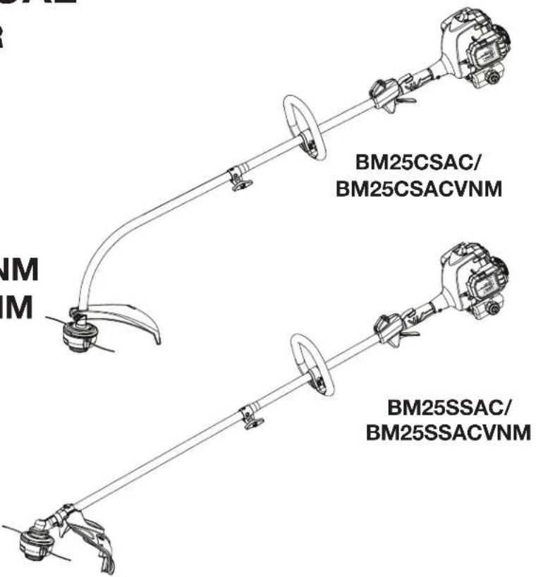
BM25CSAC/BM25CSACVNM
BM25SSAC/BM25SSACVNM
text_image
BM25CSAC/ BM25CSACVNM BM25SSAC/ BM25SSACVNMTABLE OF CONTENTS
■ General Safety Rules ....2-3
■ Specific Safety Rules....3
■ Symbols 4
■ Features .... 5
■ Assembly ....5-6
■ Operation....7-9
■ Maintenance....9-12
■ Troubleshooting....13
■ Parts Ordering/Service...... Back Page

WARNING: To reduce the risk of injury, the user read and understand the operator's manual before this product.
SAVE THIS MANUAL FOR FUTURE REFERENCE
ÍNDICE DE CONTENIDO
See this fold-out section for all the figures referenced in the operator's manual.
natural_image
Two line drawings of a person using a manual lawn power tool to spray plants in different settings (no text or symbols present)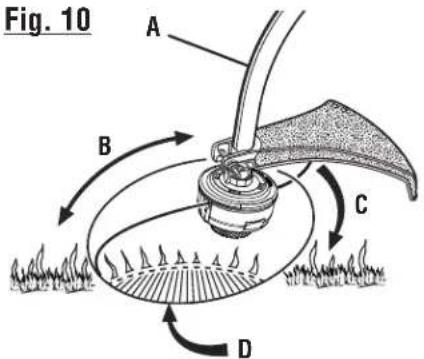
text_image
Fig. 10 A B C DFailure to follow all instructions listed below may result in electric shock, fire and/or serious personal injury.
READ ALL INSTRUCTIONS
■ For safe operation, read and understand all instructions before using this product. Follow all safety instructions. Failure to follow all safety instructions listed below, can result in serious personal injury.
■ Do not allow children or untrained individuals to use this unit.
■ Do not start or operate the engine in a confined space, building, near open windows, or in other unventilated space where dangerous carbon monoxide fumes can collect. Carbon monoxide, a colorless, odorless, and extremely dangerous gas, can cause unconsciousness or death.
- Clear the work area before each use. Remove all objects such as rocks, broken glass, nails, wire, or loose string which can be thrown or become entangled in the cutting line or blade.
■ Always wear eye protection with side shields marked to comply with ANSI Z87.1 along with hearing protection when operating this equipment. Failure to do so could result in objects being thrown into your eyes and other possible serious injuries.
■ Wear heavy, long pants, long sleeves, boots, and gloves. Do not wear loose fitting clothing, short pants, sandals, or go barefoot. Do not wear jewelry of any kind.
■ Heavy protective clothing may increase operator fatigue, which could lead to heat stroke. During weather that is hot and humid, heavy work should be scheduled for early morning or late afternoon hours when temperatures are cooler.
- Never operate this unit on the operator’s left side.
- Secure long hair above shoulder level to prevent entanglement in moving parts.
- Keep all bystanders, children, and pets at least 50 ft. away. Bystanders should be encouraged to wear eye protection. If you are approached, stop the engine and cutting attachment. In the case of bladed units, there is the added risk of injury to bystanders from being struck with the moving blade in the event of a blade thrust or other unexpected reaction of the saw.
■ Do not operate this unit when you are tired, ill, upset, or under the influence of alcohol, drugs, or medication.
■ Do not operate in poor lighting.
- Keep firm footing and balance. Do not overreach. Overreaching can result in loss of balance or exposure to hot surfaces.
■ Do not use on a ladder or unstable support. Stable footing on a solid surface enables better control of the unit in unexpected situations.
- Keep all parts of your body away from any moving part.
■ To avoid hot surfaces, never operate the unit with the bottom of the engine above waist level.
■ Do not touch area around the muffler or cylinder of the unit, these parts get hot from operation. Contact with hot surfaces could result in possible serious personal injury.
■ Always stop the engine and remove the spark plug wire before making any adjustments or repairs except for carburetor adjustments.
■ Inspect the unit before each use for loose fasteners, fuel leaks, etc. Replace any damaged parts before use.
■ Never use blades, flailing devices, wire, or rope on trimmer attachment. Never use flailing devices, wire, or rope on any attachment.
■ The cutting attachment should never rotate at idle during normal use. The cutting attachment may rotate at idle during carburetor adjustments.
It has been reported that vibrations from hand-held tools may contribute to a condition called Raynaud's Syndrome in certain individuals. Symptoms may include tingling, numbness, and blanching of the fingers, usually apparent upon exposure to cold. Hereditary factors, exposure to cold and dampness, diet, smoking, and work practices are all thought to contribute to the development of these symptoms. It is presently unknown what, if any, vibrations or extent of exposure may contribute to the condition. There are measures that can be taken by the operator to possibly reduce the effects of vibration:
a) Keep your body warm in cold weather. When operating the unit wear gloves to keep hands and wrists warm. It is reported that cold weather is a major factor contributing to Raynaud's Syndrome.
b) After each period of operation, exercise to increase blood circulation.
c) Take frequent work breaks. Limit the amount of exposure per day.
d) Keep the tool well maintained, fasteners tightened, and worn parts replaced.
If you experience any of the symptoms of this condition, immediately discontinue use and see your physician about these symptoms.
■ Mix and store fuel in a container approved for gasoline.
■ Mix fuel outdoors where there are no sparks or flames. Wipe up any fuel spillage. Move 30 ft. away from refueling site before starting engine. Slowly remove the fuel cap after stopping engine. Do not smoke when refueling.
■ Stop the engine and allow to cool before refueling or storing the unit.
GENERAL SAFETY RULES
- Allow the engine to cool; empty the fuel tank and secure the unit from moving before transporting in a vehicle.
■ Wear your protective equipment and observe all safety instructions. For units equipped with a clutch, be sure the cutting attachment stops turning when the engine idles. When the unit is turned off make sure the cutting attachment has stopped before the unit is set down.
■ We recommend taking your equipment to a qualified service center for repair, as service performed by inexperienced or unqualified persons may damage the equipment, create unsafe conditions, injury to user and/or void your warranty.
SPECIFIC SAFETY RULES
■ Inspect before use. Replace damaged parts. Make sure fasteners are in place and secure. Check for fuel leaks.
- Replace string head if cracked, chipped, or damaged in any way. Be sure the string head or blade is properly installed and securely fastened. Failure to do so can cause serious injury.
■ Make sure all guards, straps, deflectors, and handles are properly and securely attached.
■ Use only recommended or equivalent replacement line in the cutting head. Do not use any other cutting attachment. To install any other type of replacement line or cutting head to this string trimmer can result in serious personal injury. Never use, for example, wire or wire-rope, which can break off and become a dangerous projectile.
■ Never operate unit without the grass deflector in place and in good condition.
- Maintain a firm grip on both handles while trimming. Keep string head below waist level. Never cut with the string head located over 30 in. or more above the ground.
This product is intended for infrequent use by homeowners and other occasional users for such general applications as trimming light and heavy vegetation, etc. It is not intended for prolonged use. Prolonged periods of operation can cause circulatory problems in the user's hands due to vibration. For such use, it may be appropriate to use a product having an anti-vibration feature.
■ Save these instructions. Refer to them frequently and use them to instruct others who may use this tool. If you loan someone this tool, loan them these instructions also.
SYMBOLS
| The following signal words and meanings are intended to explain the levels of risk associated with this product. SYMBOL SIGNAL MEANING | ||
 | DANGER: | Indicates a hazardous situation, which, if not avoided, will result in death or serious injury. |
 | WARNING: | Indicates a hazardous situation, which, if not avoided, could result in death or serious injury. |
 | CAUTION: | Indicates a hazardous situation, that, if not avoided, may result in minor or moderate injury. |
| NOTICE: | (Without Safety Alert Symbol) Indicates information considered important, but not related to a potential injury (e.g. messages relating to property damage). | |
| Some of the following symbols may be used on this product. Please study them and learn their meaning for safe operation of this product.SYMBOL NAME EXPLANATION | ||
 | Safety Alert Indicates a potential personal injury hazard. | |
 | Read Operator's Manual | To reduce the risk of injury, user must read and understand operator's manual before using this product. |
 | Eye and Hearing Protection | Always wear eye protection with side shields marked to comply with ANSI Z87.1 along with hearing protection when operating this equipment. |
 | Wear Gloves | Wear non-slip, heavy-duty protective gloves when handling this equipment. |
 | Wear Safety Footwear | Wear non-slip safety footwear when using this equipment. |
 | Keep Bystanders Away Keep all bystanders at least 50 ft. away. | |
 | Ricochet | Thrown objects can ricochet and result in personal injury or property damage. |
 | No Blade | Do not install or use any type of blade on a product displaying this symbol. |
 | Hot Surface | To reduce the risk of injury or damage, avoid contact with any hot surface. |
 | Gasoline and Lubricant | Use unleaded gasoline intended for motor vehicle use with an octane rating of 87 [(R + M) / 2] or higher. This product is powered by a 2-cycle engine and requires pre-mixing gasoline and 2-cycle lubricant. |
FEATURES
PRODUCT SPECIFICATIONS
Line cutting width
Curved Shaft....17 in.
Straight Shaft 18 in.
Engine displacement 25cc
Line diameter....0.095 in.
KNOW YOUR PRODUCT
See Figure 1.
The safe use of this product requires an understanding of the information on the tool and in this operator's manual as well as a knowledge of the project you are attempting. Before use of this product, familiarize yourself with all operating features and safety rules.
BUMP FEED STRING HEAD
The bump feed string head allows easy line advance during trimmer operation.
ERGONOMIC DESIGN
The design of the trimmer provides for easy handling. It is designed for comfort and ease of grasp when operating in different positions and at different angles.
GRASS DEFLECTOR
The product includes a grass deflector that helps protect you from flying debris.
TOP-MOUNTED ENGINE
The top-mounted engine improves balance and is located away from the dust and debris of the cutting area.
ASSEMBLY
UNPACKING
This product requires assembly.
■ Carefully remove the items from the box. Make sure that all items listed in the Packing List are included.

WARNING:
Do not use this product if any parts in the Packing List are already assembled to your product when you unpack it. Parts on this list are not assembled to the product by the manufacturer and require customer installation. Use of a product that may have been improperly assembled could result in serious personal injury.
■ Inspect the unit carefully to make sure no damage occurred during shipping.
■ Do not discard the packing material until you have carefully inspected and satisfactorily operated the product.
■ If any parts are damaged or missing, please call 1-800-726-5760 for assistance.
PACKING LIST
Curved Shaft
Trimmer Assembly
Front Handle with Hardware
Curved Shaft Grass Deflector
Bottle of 2-Cycle Lubricant
Operator's Manual
Straight Shaft
Trimmer Assembly
Front Handle with Hardware
Straight Shaft Grass Deflector
Bottle of 2-Cycle Lubricant
Operator's Manual

WARNING:
If any parts are damaged or missing do not operate this product until the parts are replaced. Use of this product with damaged or missing parts could result in serious personal injury.
ASSEMBLY

WARNING:
Do not attempt to modify this product or create accessories not recommended for use with this product. Any such alteration or modification is misuse and could result in a hazardous condition leading to possible serious personal injury.

WARNING:
To prevent accidental starting that could cause serious personal injury, always disconnect the engine spark plug wire from the spark plug when assembling parts.
INSTALLING THE POWER HEAD TO THE ATTACHMENT
See Figure 2.

WARNING:
Never install, remove, or adjust any attachment while power head is running. Failure to stop the engine can cause serious personal injury.
The attachment connects to the power head by means of a coupler device.
■ Stop the engine and disconnect the spark plug wire.
■ Loosen the knob on the coupler of the power head shaft.
■ Push in the button located on the trimmer attachment. Align the button with the guide recess on the power head coupler and slide the two shafts together. Rotate the trimmer attachment until the button locks into the positioning hole.
NOTE: If the button does not release completely in the positioning hole, the shafts are not locked into place. Slightly rotate from side to side until the button is locked into place.
■ Tighten the knob securely.

WARNING:
Be certain the knob is fully tightened before operating equipment; check it periodically for tightness during use to avoid serious personal injury.
REMOVING THE ATTACHMENT FROM THE POWER HEAD
■ Stop the engine and disconnect the spark plug wire.
■ Loosen the knob.
■ Push in the button and twist the shafts to remove and separate ends.
ATTACHING THE FRONT HANDLE
See Figure 3.
■ Remove wing nut and bolt from the front handle.
■ Install the front handle onto the top side of the power head shaft in the area indicated by the label.
■ Place the bolt through the front handle.
NOTE: The hex bolt head fits inside the hex recess molded into one side of the handle.
■ Reinstall the wing nut.
■ Tighten wing nut securely.
ATTACHING THE GRASS DEFLECTOR

WARNING:
The line cutting blade on the grass deflector is sharp. Avoid contact with the blade. Failure to avoid contact can result in serious personal injury.
TO ATTACH THE CURVED SHAFT GRASS DEFLECTOR
See Figure 4.
■ Remove bolt and wing nut from grass deflector.
■ Press the grass deflector onto the bottom of the curved shaft as shown.
■ Insert the bolt through the grass deflector and the bracket on the curved shaft.
■ Place the wing nut on the bolt and tighten securely.
TO ATTACH THE STRAIGHT SHAFT GRASS DEFLECTOR
See Figure 5.
■ Remove the bolt from the grass deflector.
- Insert the tab on the mounting bracket in the slot on the grass deflector.
■ Align the screw hole in the mounting bracket with the screw hole in the grass deflector.
■ Insert the bolt through the mounting bracket and into the grass deflector.
■ Tighten the bolt securely.
OPERATION

WARNING:
Do not allow familiarity with this product to make you careless. Remember that a careless fraction of a second is sufficient to inflict serious injury.

WARNING:
Always wear eye protection with side shields marked to comply with ANSI Z87.1, along with hearing protection. Failure to do so could result in objects being thrown into your eyes and other possible serious injuries.

WARNING:
Never use blades, flailing devices, wire, or rope on this product. Do not use any attachments or accessories not recommended by the manufacturer of this product. The use of attachments or accessories not recommended can result in serious personal injury.
NOTICE:
The spark arrestor on this product has not been evaluated by the USDA Forest Service and cannot be used on U.S. forest lands. In addition, product users must comply with Federal, State, and local fire prevention regulations. Check with appropriate authorities. Contact customer service or a qualified service center to purchase a replacement spark arrestor.
NOTICE:
Before each use, inspect the entire product for damaged, missing, or loose parts such as screws, nuts, bolts, caps, etc. Tighten securely all fasteners and caps and do not operate this product until all missing or damaged parts are replaced. Please contact customer service or a qualified service center for assistance.
Do not use E15 or E85 fuel in this product. It is a violation of federal law and will damage the unit and void your warranty. Only use unleaded gasoline containing up to 10% ethanol.
NOTE: To improve performance when using oxygenated fuels, we recommend the use of Ethanol Shield 2-cycle lubricant.
FUELING AND REFUELING THE TRIMMER

WARNING:
Gasoline and its vapors are highly flammable and explosive. To prevent serious personal injury and property damage, handle it with care. Keep away from ignition sources and open flames, handle outdoors only, do not smoke and wipe up spills immediately.
FUEL MIXTURE
This product is powered by a 2-cycle engine and requires pre-mixing gasoline and 2-cycle lubricant. Pre-mix unleaded gasoline and 2-cycle engine lubricant in a clean container approved for gasoline. DO NOT mix quantities larger than usable in a 30-day period.
Recommended fuel: This engine is certified to operate on unleaded gasoline intended for automotive use.
NOTE: We recommend you use Ethanol Shield 2-cycle lubricant or an equivalent high-quality synthetic 2-cycle lubricant in this product. Mix at 2.6 oz. per gallon (US).
Do not use automotive lubricant or 2-cycle outboard lubricant.
HIGH QUALITY 2-CYCLE ENGINE LUBRICANT SOLINE LUBRICANT

(US) (3.8 liter) 2.6 oz. (76 ml)
(US) (9.5 liter) 6.4 oz. (189 ml)
FILLING TANK
■ Clean surface around fuel cap to prevent contamination.
■ Loosen fuel cap slowly. Rest the cap on a clean surface.
■ Carefully pour fuel mixture into the tank. Avoid spillage.
■ Prior to replacing the fuel cap, clean and inspect the gasket.
■ Immediately replace fuel cap and hand tighten. Wipe up any fuel spillage.
NOTE: It is normal for smoke to be emitted from a new engine after first use.

WARNING:
Always shut off engine before fueling. Never remove fuel cap or add fuel to a machine with a running or hot engine. Make sure the unit is sitting on a flat, level surface and only add fuel outdoors. If the engine is hot, let the unit cool for at least five minutes before adding fuel. After fueling, immediately replace fuel cap and tighten securely. Move at least 30 ft. from refueling site before starting engine. Do not smoke and stay away from open flames and sparks! Failure to follow these instructions could result in a fire and cause serious personal injury.
OPERATION
STARTING AND STOPPING
See Figures 6 - 8.
Trimmer should be on a flat, bare surface for starting.
To start a cold engine:
■ Lay the product on a flat, bare surface.
■ Push the primer bulb approximately ten times.
■ Set the choke lever to FULL CHOKE.
■ Depress lock-out button and squeeze throttle trigger fully and pull starter grip and rope sharply until engine attempts to start (no more than 4x).
■ Set the choke lever to HALF CHOKE.
■ Pull starter grip and rope until engine runs, no more than 6 pulls.
- Allow engine to run for 10 seconds, then set the choke lever to RUN.
NOTE: In cooler environments, additional pulls of the starter grip and rope may be required with the choke lever in the FULL CHOKE position.
To start a warm engine:
■ Lay the product on a flat, bare surface.
■ Push the primer bulb up to ten times.
■ Set the choke lever to RUN.
■ Depress lock-out button and squeeze throttle trigger fully, pull the starter cord.
NOTE: If the product does not start, repeat the previous steps.
To stop the engine:
■ To stop the engine, depress the STOP switch to the stop position “STOP”.
IF ASSISTANCE IS REQUIRED FOR THIS PRODUCT:
Do not return this product to the retail store where it was purchased. Please call our Customer Service Department for any issues you may have.
For Help Call: 1-800-726-5760
Engine housing can become hot during trimmer operation. Do not rest or place your arm, hand, or any body part against the engine housing during trimmer operation. Only hold the trimmer as shown in figure 9 with all body parts clear of engine housing. Extended contact with the engine housing can result in burns or other injuries.

WARNING:
Always position the unit on the operator's right side. The use of the unit on the operator's left side will expose the user to hot surfaces and can result in possible burn injury.

WARNING:
To avoid burns from hot surfaces, never operate unit with the bottom of the engine above waist level.
Hold the trimmer with your right hand on the rear handle and your left hand on the front handle. Keep a firm grip with both hands while in operation. Trimmer should be held at a comfortable position with the rear handle about hip height. Always operate trimmer in RUN position. Cut tall grass from the top down. This will prevent grass from wrapping around the shaft housing and string head which could cause damage from overheating. If grass becomes wrapped around the string head, STOP THE ENGINE, disconnect the spark plug wire, and remove the grass. Prolonged cutting at partial throttle will result in lubricant dripping from the muffler.

WARNING:
Always hold the string trimmer away from the body keeping clearance between the body and the product. Any contact with the housing or string trimmer cutting head can result in burns and/or other serious personal injury.
CUTTING TIPS
See Figures 9 - 11.
■ Avoid hot surfaces by always keeping the tool away from your body. (Proper operating position shown in figure 9.)
- Keep the trimmer tilted toward the area being cut; this is the best cutting area.
■ The curved shaft trimmer cuts when passing the unit from right to left. The straight shaft trimmer cuts when passing the unit from left to right. This will avoid throwing debris at the operator. Avoid cutting in the dangerous area shown in illustration.
■ Use the tip of line to do the cutting; do not force string head into uncut grass.
■ Wire and picket fences cause extra line wear, even breakage. Stone and brick walls, curbs, and wood may wear line rapidly.
■ Avoid trees and shrubs. Tree bark, wood moldings, siding, and fence posts can easily be damaged by the line.
OPERATION
TO ADVANCE THE CUTTING LINE
Line advance is controlled by tapping the string head on grass while running engine at full throttle.
■ Run engine at full throttle.
■ Tap the knob on ground to advance line. The line advances each time the knob is tapped. Do not hold the knob on the ground.
NOTE: The line trimming cut-off blade on the grass deflector will cut the line to the correct length.
NOTE: If the line is worn too short you may not be able to advance the line by tapping it on the ground. If so, stop the engine and manually advance the line.
To advance the cutting line manually:
■ Stop the engine and disconnect the spark plug wire.
■ Push the knob in while pulling on line(s) to manually advance the line.
GRASS DEFLECTOR LINE TRIMMING CUT-OFF BLADE
See Figure 12.
The trimmer is equipped with a line trimming cut-off blade on the grass deflector. For best cutting, advance line until it is trimmed to length by the cut-off blade. Advance the line whenever you hear the engine running faster than normal, or when trimming efficiency diminishes. This will maintain best performance and keep the line long enough to advance properly.
MAINTENANCE
Normal maintenance, replacement or repair of emission control devices and systems may be performed by any qualified repair establishment or individual with original or equivalent parts. Warranty and recall repairs must be performed by a authorized service center; please contact customer service for assistance.

WARNING:
Before inspecting, cleaning, or servicing the machine, shut off engine, wait for all moving parts to stop, and disconnect spark plug wire and move it away from spark plug. Failure to follow these instructions can result in serious personal injury or property damage.

WARNING:
Always wear eye protection with side shields marked to comply with ANSI Z87.1, along with hearing protection. Failure to do so could result in objects being thrown into your eyes and other possible serious injuries.

WARNING:
When servicing, use only recommended or equivalent replacement parts. Use of any other parts could create a hazard or cause product damage.
NOTICE:
Periodically inspect the entire product for damaged, missing, or loose parts such as screws, nuts, bolts, caps, etc. Tighten securely all fasteners and caps and do not operate this product until all missing or damaged parts are replaced. Please contact customer service or a qualified service center for assistance.
GENERAL MAINTENANCE
Avoid using solvents when cleaning plastic parts. Most plastics are susceptible to damage from various types of commercial solvents and may be damaged by their use. Use clean cloths to remove dirt, dust, lubricant, grease, etc.

WARNING:
Do not at any time let brake fluids, gasoline, petroleum-based products, penetrating lubricants, etc., come in contact with plastic parts. Chemicals can damage, weaken or destroy plastic which could result in serious personal injury.
LINE REPLACEMENT
See Figure 13.
Use only .095 in. trimmer line. Use original manufacturer's replacement line for best performance.
■ Stop the engine and disconnect the spark plug wire.
■ Rotate the bump knob clockwise as necessary to align the arrows on the bump knob with the arrows on the string head housing.
MAINTENANCE
- Cut one piece of trimmer line 16 ft. long. Insert the line into the eyelet on the string head housing. Push until the end of the line comes out the other side of the housing. Pull the line until equal amounts of line appear on both sides of the housing.
NOTE: Line may jam if more than 16 ft. is loaded.
■ Rotate the bump knob clockwise to wind the line on the spool until approximately 6 in. of line is showing on each side.
■ Push the bump knob down while pulling on line(s) to manually advance the line.
CLEARING LINE JAM AND/OR REPLACING BUMP KNOB
See Figures 14 - 15.
■ Stop the engine and disconnect the spark plug wire.
■ Depress the tabs on the side of the string head housing to remove the lower string head housing.
NOTE: The housing is spring loaded and will self eject when the tabs are depressed. It is not necessary to remove the upper string head housing from the drive shaft.
■ Push the spool and bump knob through the string head housing and remove the string from the spool.
If replacing the bump knob, remove the old knob from the spool. Align the knob ribs with the spool slots and place the new bump knob onto the spool. If you are not replacing the bump knob, skip this step.
■ Insert the bump knob and spool assembly through the opening in the string head housing.
■ Align the slots on the lower string head housing with the tabs on the upper string head housing.
■ Push the housing together until the tabs snap into place.
NOTE: Hold the spool by the knob while completing the installation.
■ Install line as described in Line replacement.
CLEANING THE EXHAUST PORT, MUFFLER, AND SPARK ARRESTOR
NOTICE:
The spark arrestor on this product has not been evaluated by the USDA Forest Service and cannot be used on U.S. forest lands. In addition, product users must comply with Federal, State, and local fire prevention regulations. Check with appropriate authorities. Contact customer service or a qualified service center to purchase a replacement spark arrestor.
NOTE: Depending on the type of fuel used, the type and amount of lubricant used, and/or your operating conditions, the exhaust port, muffler, and/or spark arrestor screen may become blocked with carbon deposits. If you notice a power loss with your gas powered tool, you may need to
remove these deposits to restore performance. We highly recommend that only qualified service technicians perform this service.
The spark arrestor must be cleaned or replaced every 50 hours or yearly to ensure proper performance of your product. Spark arrestors may be in different locations depending on the model purchased. Please contact your nearest service dealer for the location of the spark arrestor for your model.
IDLE SPEED ADJUSTMENT
See Figure 16.

WARNING:
The cutting head will move when adjusting the idle speed. Wear all protective clothing and keep all bystanders, children, and pets at least 50 ft. away. Make adjustments with the unit supported by hand so that the blade/cutting head does not contact the ground or any object. Keep all parts of your body away from the cutting head and muffler. Failure to follow these instructions could result in serious personal injury.
If the cutting attachment turns at idle, the idle speed screw needs adjusting on the engine. Turn the idle speed screw counterclockwise to reduce the idle RPM and stop the cutting attachment movement. If the cutting attachment still moves at idle speed, contact a service dealer for adjustment and discontinue use until the repair is made.

WARNING:
The cutting attachment should never turn at idle. Turn the idle speed screw counterclockwise to reduce the idle RPM and stop the cutting attachment, or contact a service dealer for adjustment and discontinue use until the repair is made. Serious personal injury could result from the cutting attachment turning at idle.
CLEANING THE AIR FILTER
See Figures 17 - 18.
For proper performance and long life, keep air filter clean.
■ Remove the air filter cover by pushing down on the latches while gently pulling off the cover.
■ Remove the air filter.
■ Clean the foam filter element with warm soapy water. Rinse and let dry.
NOTE: If the foam filter element is damaged, it should be replaced.
■ Apply a light coat of engine oil to the foam filter element, then squeeze it out.
■ Reinstall the air filter.
NOTE: Make sure the filter is seated properly inside the cover. Installing the filter incorrectly will allow dirt to enter the engine, causing rapid engine wear.
MAINTENANCE
■ Replace the air filter cover by placing the slots on the air filter cover over the tabs on the housing, then push the cover down until it snaps securely in place.
FUEL CAP, TANK, AND LINES

WARNING:
Check for fuel leaks. A leaking fuel cap, tank, or line is a fire hazard and must be replaced immediately. If you find any leaks, correct the problem before using the product. Failure to do so could result in a fire that could cause serious personal injury.
The fuel cap contains a non-serviceable filter and a check valve. A clogged fuel filter will cause poor engine performance. If performance improves when the fuel cap is loosened, the check valve may be faulty or filter clogged. Replace the fuel cap if required.
SPARK PLUG REPLACEMENT
The spark plug for this engine may be replaced using a Torch L7RTC, Champion RCJ6Y or equivalent spark plug. The spark plug gap should be set at .025 in. Use a recommended or equivalent replacement and replace annually.
NOTICE:
Be careful not to cross-thread the spark plug. Cross-threading will seriously damage the product.
STORING THE PRODUCT
■ Clean all foreign material from the product. Store idle unit indoors in a dry, well-ventilated area that is inaccessible to children. Keep away from corrosive agents such as garden chemicals and de-icing salts.
■ Abide by all ISO and local regulations for the safe storage and handling of gasoline.
When storing 1 month or longer:
- Drain all fuel from tank into a container approved for gasoline. Run engine until it stops.
Your engine is configured for operation below 2000 feet altitude at the factory. Your engine must be re-configured for operation above 2000 feet altitude. Operating the engine with the wrong engine configuration at a given altitude may increase its emissions, decrease fuel efficiency, degrade performance and cause irreversible damage. Engines configured for high altitude operation cannot be operated in standard altitude conditions. A qualified service center should ensure that your engine is properly configured for your location.
MAINTENANCE
THIS PRODUCT WAS MANUFACTURED WITH A CATALYST MUFFLER
Congratulations! You have made an investment toward protecting the environment. In order to maintain this product's original emission level, please refer to the maintenance section below.
MAINTENANCE SCHEDULE
Inspect For Clean Replace Replace
Maintenance Damage Before Every Every 25 Hours Every
Part Each Use 5 Hours or Yearly 50 Hours
*CATALYTIC MUFFLER ASSEMBLY....X
SPARK SCREEN ....X
* AIR FILTER ASSY
includes:
Filter Screen....X
*CARBURETOR ASSY
includes:
Gaskets....X
* FUEL TANK ASSY
includes:
Fuel Lines....X
Fuel Cap....X
Fuel Filter....X
*IGNITION ASSY
includes:
Spark Plug....X
*NOTICE: THE USE OF EMISSION CONTROL COMPONENTS OTHER THAN THOSE DESIGNED FOR THIS UNIT IS A VIOLATION OF FEDERAL LAW.
This product has a Three-year Limited Warranty for personal, family, or household use (30 days for business or commercial use).
For warranty details, visit www.blackmaxtools.com or call (toll free) 1-800-726-5760.
TROUBLESHOOTING
| PROBLEM POSSIBLE CAUSE SOLUTION | ||
| Engine will not start No spark | No fuel | Clean or replace spark plug. Reset spark plug gap. Refer to Spark Plug Replacement earlier in this manual. |
| Engine is flooded | Push primer bulb until bulb is full of fuel. If bulb does not fill, primary fuel delivery system is blocked. Contact a qualified service dealer. If primer bulb fills, engine may be flooded, proceed to next item. | |
| Set the choke lever to the FULL CHOKE position. Squeeze the trigger and pull the starter grip and rope repeatedly until the engine starts and runs. | ||
| NOTE: Depending on the severity of the flooding, this may require numerous pulls of the rope. | ||
| Engine does not reach full speed and emits excessive smoke | Incorrect lubricant/fuel mixture | Use fresh fuel and the correct 2-cycle lubricant mix. (50:1). |
| Air filter screen is dirty | Clean air filter screen. Refer to Cleaning the Air Filter earlier in this manual. | |
| Spark arrestor screen is dirty | Contact a qualified service dealer. | |
| Spark plug fouled | Clean or replace spark plug. Reset spark plug gap. Refer to Spark Plug Replacement earlier in this manual. | |
| Engine starts, runs, and accelerates but will not idle | Idle speed screw on carburetor needs adjustment | Turn idle speed screw clockwise to increase idle speed. See Figure 16. |
| Line will not advance Line is we | ded to itself | Lubricate line with silicone spray. |
| Not enough line on spool | Install more line. Refer to the applicable line replacement section in this manual. | |
| Line is worn too short | Pull lines while alternately pressing down on and releasing bump knob. | |
| Line is tangled on spool | Remove line from spool and rewind. Refer to the applicable line replacement section in this manual. | |
| Engine speed is too slow | Advance line at full throttle. | |
| Grass wraps around drive shaft housing and string head | Cutting tall grass at ground level | Cut tall grass from the top down to prevent wrapping. |
| Operating trimmer at part throttle | Operate trimmer at full throttle | |
If problem persists after trying the above solutions, contact customer service or a qualified service center for assistance.
NOTICE:
As the equipment owner, you are responsible for the performance of the required maintenance listed in the Maintenance section. It is recommended that you retain all receipts covering maintenance on your equipment. Neglecting or failing to perform the required maintenance may increase emissions, decrease fuel efficiency, degrade performance, cause irreversible engine damage and/or void your warranty.
MEZCLA DE COMBUSTIBLE
REEMPLAZO DE LA BUJÍA
For parts or service, contact your service dealer. Please call 1-800-726-5760 or visit us online at www.blackmaxtools.com for assistance. Be sure to provide all relevant information when you call or visit. A replacement parts list is also available online.
REPAIR PARTS
The item, manufacturing, and serial numbers of this product are found on a plate or label attached to the housing. Please record these numbers in the spaces provided below.
ITEM NO. ____
MANUFACTURING NO. ____
SERIAL NO. ____
