Sigma 6903 - Office BDI - Free user manual and instructions
Find the device manual for free Sigma 6903 BDI in PDF.


| Product Type | Office Desk |
| Brand | BDI |
| Model | Sigma 6903 |
| Main Material | Glass top, metal frame and legs |
| Top Surface | Tempered glass with rectangular alignment blocks |
| Leg Design | Left and right metal legs (C8, C9) |
| Wire Management | Upper and lower troughs (C6, C7), cord conduit (C10) |
| Storage | Flip-down metal tray (C4) for surge protector, drawer with liner (C5) |
| Panels | Front panel (C3) and back panel (C2) with magnetic attachment |
| Hardware Included | M6 x 12mm screws (22 pcs), 4mm hex wrench (T1) |
| Assembly Required | Yes, with hex wrench; two persons recommended for some steps |
| Power Requirements | None (desk does not require power; for surge protector placement only) |
| Intended Use | Indoor, on level floors |
| Cleaning | Glass cleaner for glass top; damp cloth for other surfaces |
| Product Registration | Available at www.bdiusa.com/product-registration/ |
| Warranty | Contact BDI customer service (customerservice@bdiusa.com) |
Frequently Asked Questions - Sigma 6903 BDI
User questions about Sigma 6903 BDI
0 question about this device. Answer the ones you know or ask your own.
Ask a new question about this device
Download the instructions for your Office in PDF format for free! Find your manual Sigma 6903 - BDI and take your electronic device back in hand. On this page are published all the documents necessary for the use of your device. Sigma 6903 by BDI.
USER MANUAL Sigma 6903 BDI
Product Registration
Registering your new BDI product allows us to send you important product updates, service information and helpful hints related to your BDI products. Register today and you will be entered to win free a BINK table from BDI. www.bdiusa.com/product-registration/
Placement and Maintenance
Sigma™ Office furniture is designed for indoor use on level floors. Clean glass with glass cleaner, and other surfaces with a moist cloth.
Your Sigma™ Office furniture is engineered for easy assembly. Carefully follow this procedure to prevent any damage. Do not use power tools for assembly of this product.
Step 1
Unpack and identify the parts listed below. The assembly workspace should be a non-marring surface such as carpet. For missing hardware pieces, please contact BDI Customer Service at: customerservice@bdiusa.com.
For all other concerns, please contact your BDI retailer.
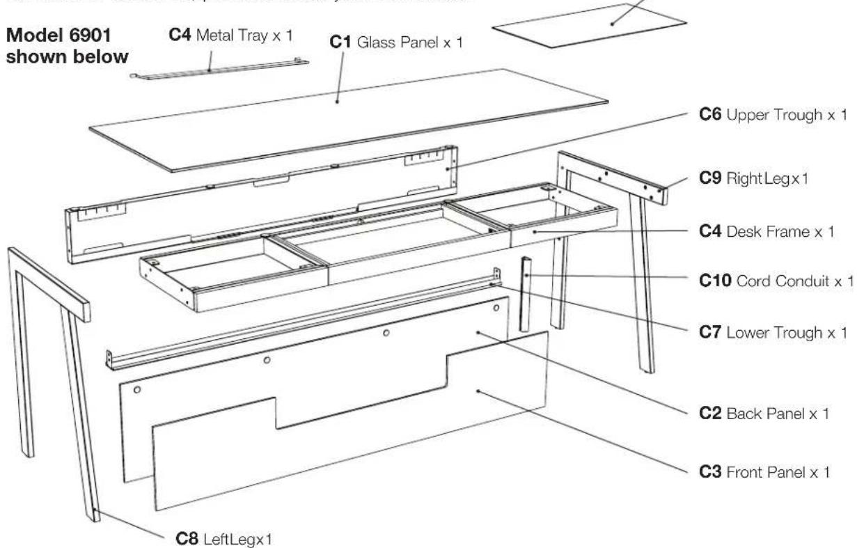
Hardware:

Designed by BDI Studio. These distinctive product configurations are protected by US and international patents, trade dress, and/or copyright laws. Sigma & BDI are trademarks of Becker Designed, Inc. All rights reserved. ©2019, BDI Made in Turkey. 02.18.2019
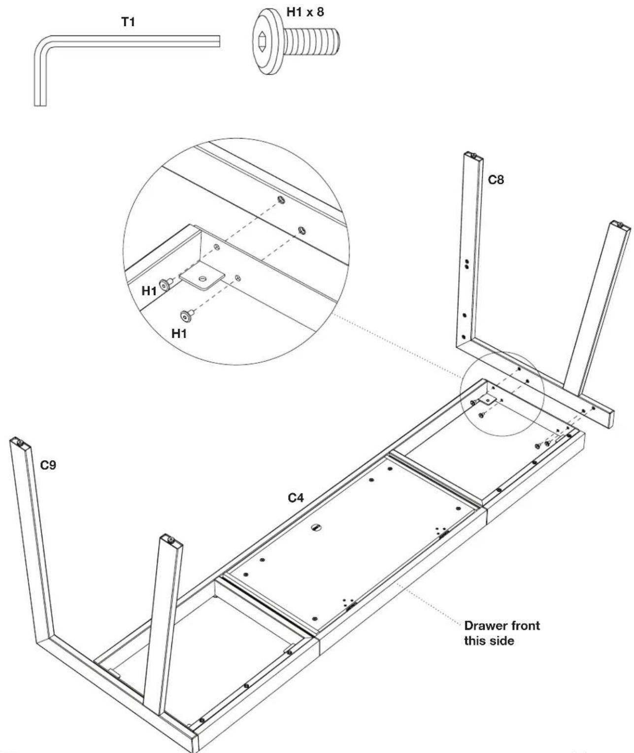
Step 2 - Place desk frame C4 upside down on a padded surface, such as a carpet. Attach left leg C8 and right leg C9 to desk frame C4 using screws H1 and hex wrench T1.
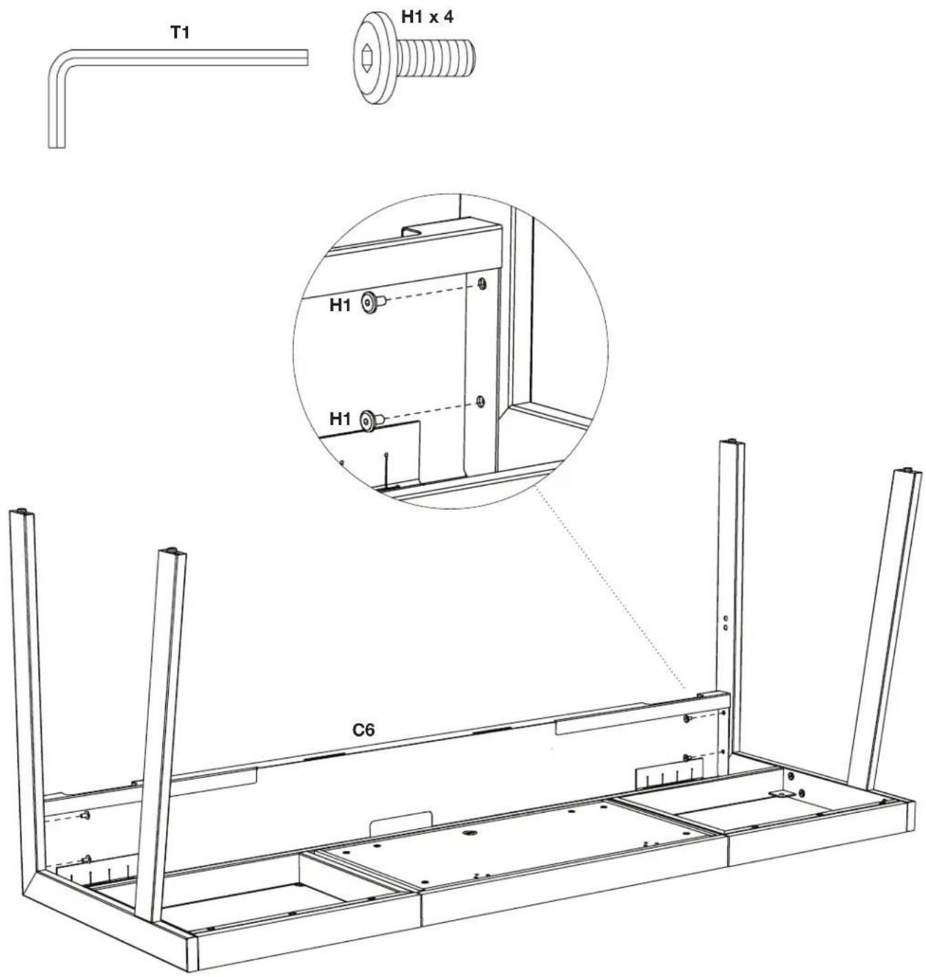
Step 3 - Orient the upper trough C6 as shown between the back leg frames. Attach the upper trough C6 to the leg frames with screws H1 and hex wrench T1.
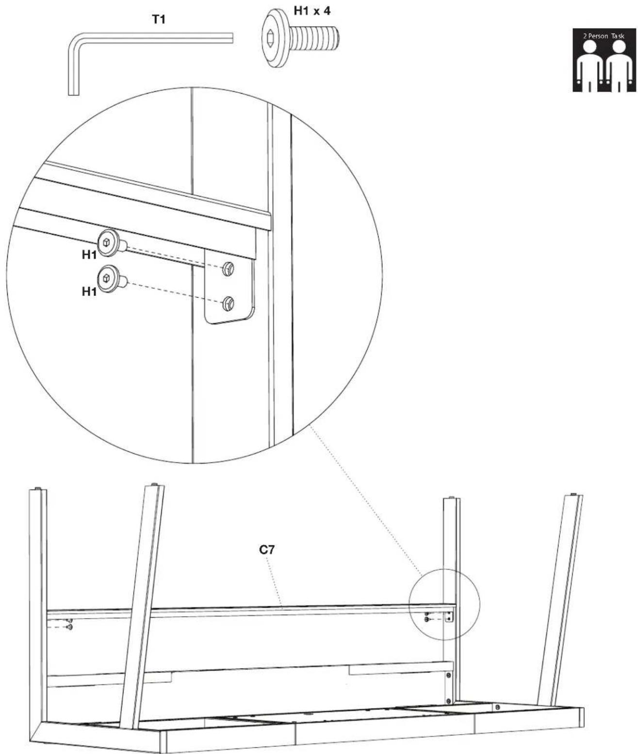
Step 4 - With help from another person, attach lower trough C7 to inside of left and right leg using screws H1 and hex wrench.
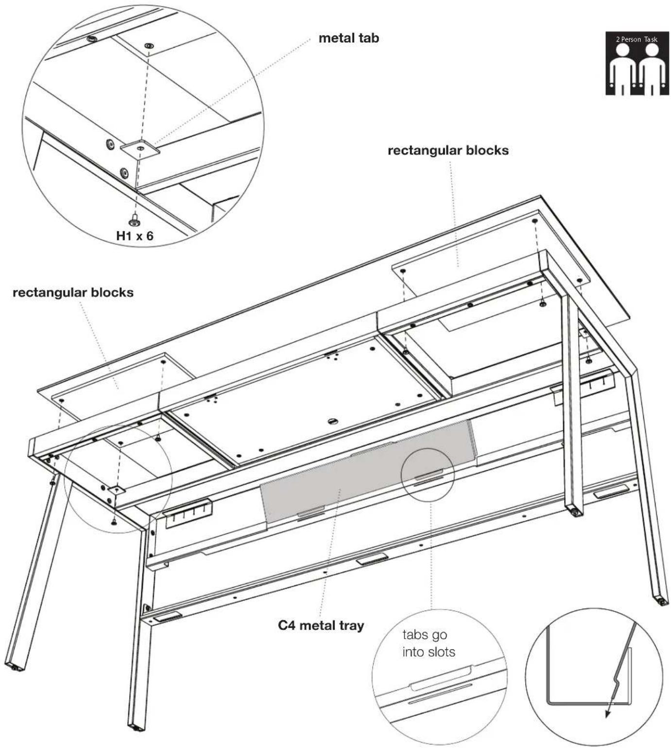
Step 5 - With the help of another person, position the desk on its feet. Carefully position the glass top C1 on top of the desk with the rectangular blocks aligning with the rectangular openings on either side of the drawer. Attach the glass top C1 to the desk frame using screws H1 (going through the 6 metal tabs) and tighten with the hex wrench.
Step 6 - Install the metal tray C4 by inserting the 2 bent metal tabs into the corresponding slots on the bottom of the top trough as shown.
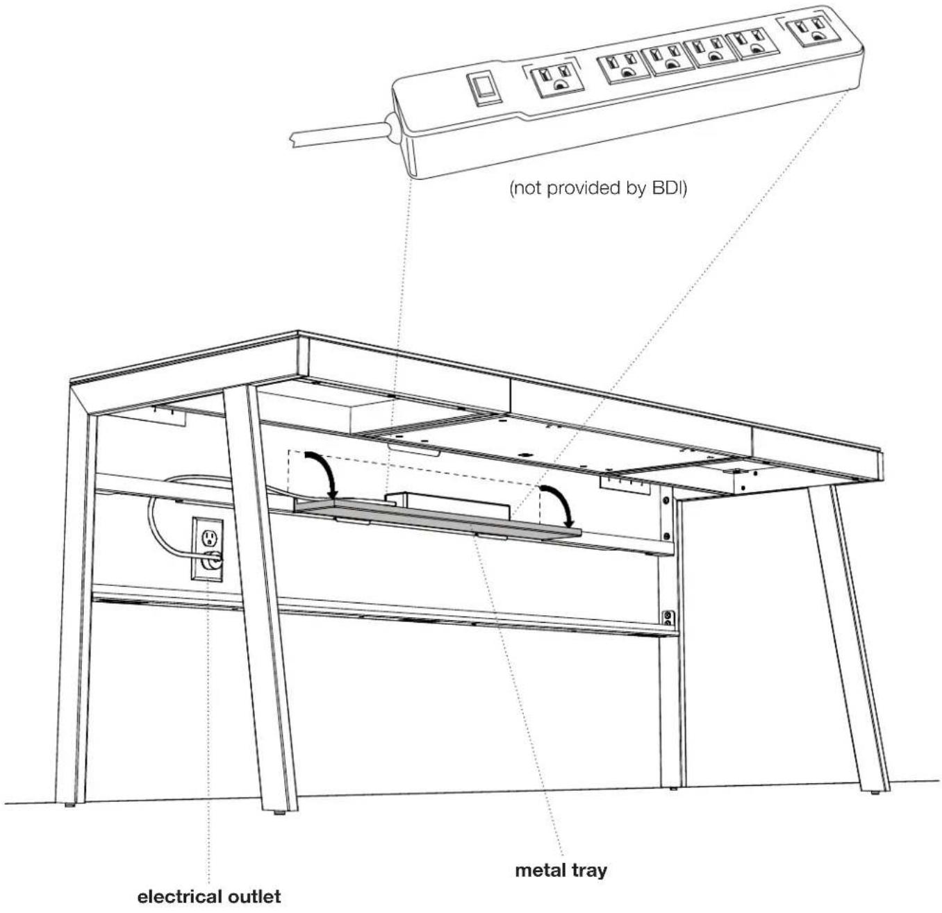
Step 6 - The Sigma desk provides a flip down metal tray designed to hold surge protectors. Lower the metal tray as shown. Position your surge protector. Use the slots in the upper and/or lower troughs to route the cord to a electrical outlet.
Note: The Sigma Desk is designed to permit placement in front of an electrical outlet for easier wiring access (as shown below).
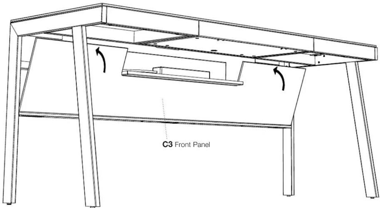
Step 7 - Install Front Panel C3 as shown. The top inside has pre-installed magnets that hold the panel in place.
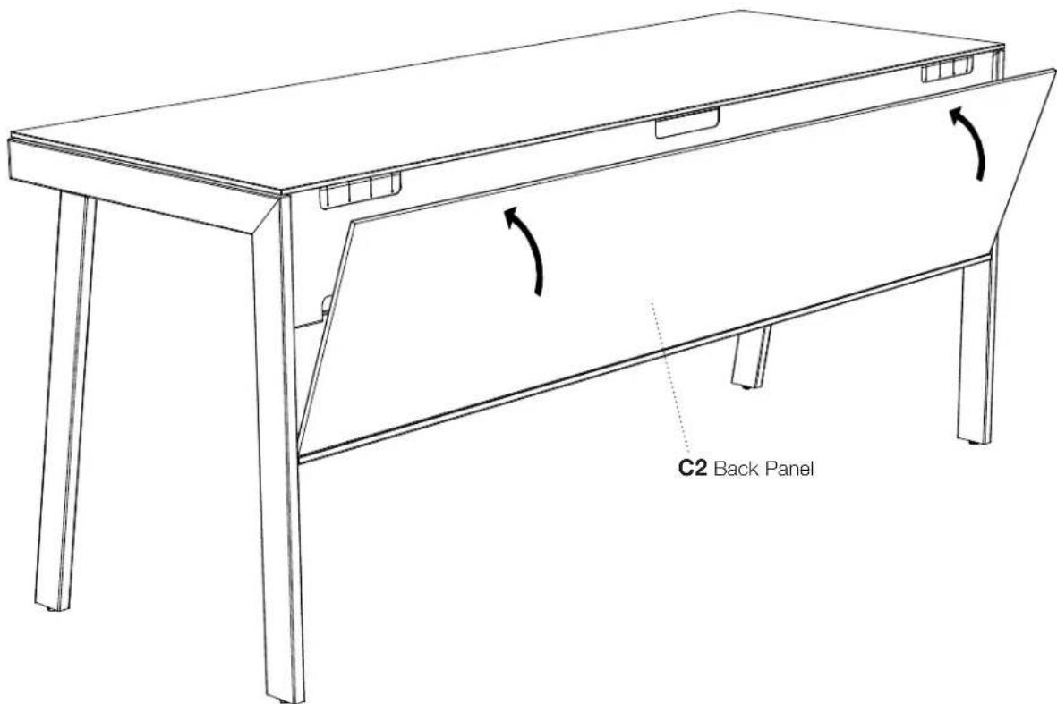
Step 8 - The Back Panel C2 conceals wire management when the desk is located in the middle of a room. Install C2 as shown. The top inside has pre-installed magnets that hold the panel in place.
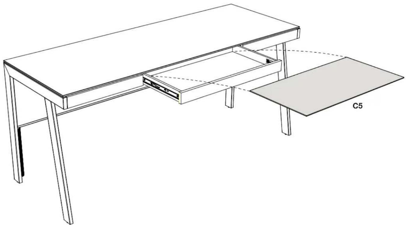
Step 9 - Open the drawer and Install the drawer liner C5.
natural_image
Line drawing of a simple wooden table with a drawer and a separate flat base, labeled C5 (no text or symbols on the diagram itself)Step 10 - (Optional)
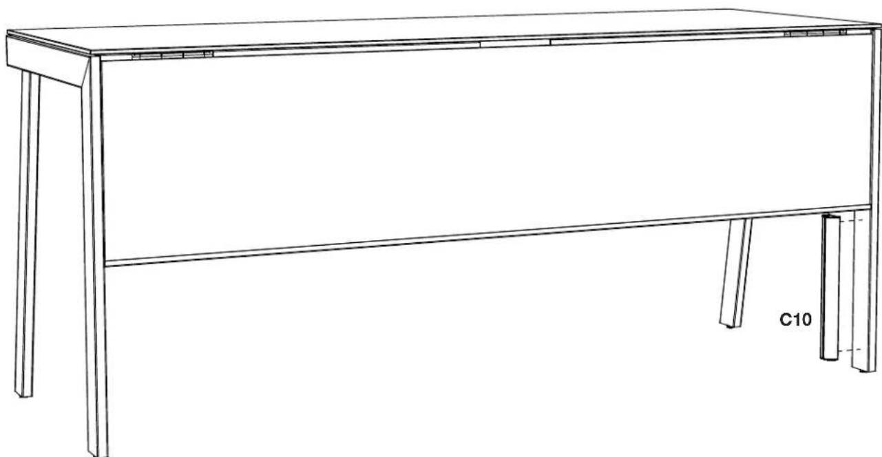
If plugging into a floor outlet, the cord conduit C10 can be attached to one of the back legs. Remove the adhesive backing from the back of the cord conduit and stick it directly onto the inside edge of the leg closest to the outlet. Press firmly. Route cords inside.
natural_image
Line drawing of a simple wooden table with four legs and a flat top, labeled C10 (no text or symbols on the table itself)Brand : BDI
Model : Sigma 6903
Category : Office