Patio SR 2-125 - Pregnant SONANCE - Free user manual and instructions
Find the device manual for free Patio SR 2-125 SONANCE in PDF.


| Product Type | Outdoor Speaker |
| Brand | Sonance |
| Model | Patio SR 2-125 |
| Driver Configuration | 2-way |
| Woofer | 5.25" polypropylene |
| Tweeter | 1" aluminum dome |
| Power Handling (RMS) | 125 W |
| Impedance | 8 ohms |
| Frequency Response | 50 Hz - 20 kHz |
| Sensitivity | 90 dB (1W/1m) |
| Dimensions (H x W x D) | 12 x 6.5 x 5.5 in |
| Weight | 4.8 lb |
| Enclosure Material | UV-stable ABS plastic |
| Grille Material | Aluminum mesh |
| Weather Rating | IP66 |
| Mounting | Integrated keyhole bracket |
| Terminals | Gold-plated spring-loaded |
| Color Options | Black or White |
| Included Accessories | Quick start guide, mounting hardware |
Frequently Asked Questions - Patio SR 2-125 SONANCE
User questions about Patio SR 2-125 SONANCE
0 question about this device. Answer the ones you know or ask your own.
Ask a new question about this device
Download the instructions for your Pregnant in PDF format for free! Find your manual Patio SR 2-125 - SONANCE and take your electronic device back in hand. On this page are published all the documents necessary for the use of your device. Patio SR 2-125 by SONANCE.
USER MANUAL Patio SR 2-125 SONANCE
SR 2-125 TWO-CHANNEL AMP
TABLE OF CONTENTS
2 Important Safety Instructions
4 Introduction and Box Contents
5 Product Features
5 Product Preparation
6 Installation
6 Technical Specifications
7 Architectural Specification
7 Technical Assistance and Service
9 Warranty
READ THIS DOCUMENT IN ITS ENTIRETY BEFORE ATTEMPTING INSTALLATION.
- Read these instructions.
- Keep these instructions.
- Heed all warnings.
- Follow all instructions.
- Do not use this apparatus near water.
- Clean only with a dry cloth.
- Do not block any ventilation openings. Install in accordance with the manufacturer's instructions.
- Do not install near any heat sources such as radiators, heat registers, stoves, or other apparatus (including amplifiers) that produce heat.
- Only use attachments/accessories specified by Sonance.
- Refer all servicing to qualified service personnel.
DSP AMPLIFIER
SR 2-125 TWO-CHANNEL AMP
IMPORTANT SAFETY INFORMATION
You should always follow these basic safety precautions when using your SR 2-125 amplifier to reduce the risk of fire, electric shock, and injury to persons:
- Read and retain instructions: Read all the safety and operating instructions before operating the amplifier, and retain them for future reference.
- Heed warnings: Adhere to all warnings and precautions listed on the amplifier and in the operating instructions.
- Follow instructions: Follow all operating instructions.
- Water: Never use the amplifier next to water.
- Carts and stands: The amplifier should be used only with a cart or stand that is recommended by the manufacturer. An amplifier and cart combination should be moved with care.
- CAUTION: TO PREVENT ELECTRIC SHOCK, DO NOT USE THE POLARIZED PLUG WITH AN EXTENSION CORD, RECEPTACLE, OR OTHER OUTLETS UNLESS THE BLADES CAN BE FULLY INSERTED TO PREVENT BLADE EXPOSURE.
- Ventilation: Situate the amplifier so that its location does not interfere with its proper ventilation.
- Heat: Situate the amplifier away from heat sources such as radiators, stoves, or other appliances (including amplifiers) that produce heat.
- Grounding or polarization: Grounding or polarization are precautions that should be taken so that these attributes are not defeated.
- Power-cord protection: Route power supply cords so that they will not be walked on or pinched by items placed on or against them.
- Cleaning: To clean the amplifier, use "canned air" or wipe the amplifier with a soft cloth. Do not use solvents as they may damage the amplifier.
- Non-use periods: Unplug the amplifier's power cord from the outlet when the amplifier will be left unused for a long period of time.
- Object entry: Care should be taken so that objects do not fall through the opening of the enclosure.
- Moisture: Do not expose the amplifier to dripping or splashing. Do not place objects filled with liquids, such as vases, on the amplifier.
-
Damage requiring service: Have the amplifier serviced by a qualified service personnel when:
-
The power supply cord or the plug has been damaged.
- Objects have fallen, or liquid has been spilled into the amplifier.
- The amplifier has been exposed to rain.
- The amplifier does not appear to operate normally or exhibits a marked change in performance.
- The amplifier has been dropped, or the enclosure damaged.
- Servicing: The user should not attempt to service the amplifier beyond that described in the operating instructions. All other servicing should be referred to qualified service personnel.
- Lifting: Improperlifting of the 11 lbs. SR2-125 amplifier can cause personal injury.
- Power requirement: Do not connect the SR 2-125 amplifier to the accessory outlet of any other component. A minimum 15 amp (20 amp preferred) grounded wall outlet is required.
WARNING: THE POWER (MAINS) PLUG SERVES AS THE AMPLIFIER'S DISCONNECT DEVICE. THE DISCONNECT DEVICE SHALL REMAIN READILY OPERABLE DURING OPERATION. TO ENSURE THAT THE DISCONNECT DEVICE (POWER PLUG) IS EASILY ACCESSIBLE, THE USER SHALL NOT PLACE THE AMPLIFIER IN A CONFINED AREA DURING OPERATION.
- Storms: To prevent damage to components, unplug all electronic equipment during thunderstorms.
text_image
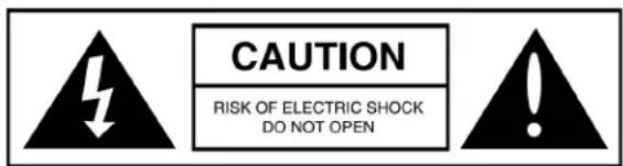
CAUTION RISK OF ELECTRIC SHOCK DO NOT OPENCAUTION: TO REDUCE THE RISK OF ELECTRIC SHOCK, DO NOT REMOVE COVER (OR BACK) NO USER SERVICEABLE PARTS INSIDE REFER SERVICING TO AUTHORIZED SERVICE PERSONNEL.
text_image
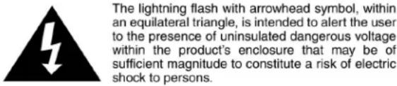
The lightning flash with arrowhead symbol, within an equilateral triangle, is intended to alert the user to the presence of uninsulated dangerous voltage within the product's enclosure that may be of sufficient magnitude to constitute a risk of electric shock to persons.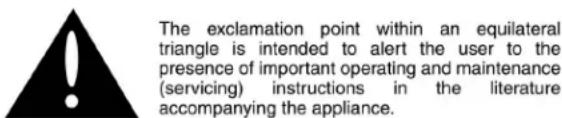
text_image
The exclamation point within an equilateral triangle is intended to alert the user to the presence of important operating and maintenance (servicing) instructions in the literature accompanying the appliance.WARNING: TO PREVENT FIRE OR SHOCK HAZARD, DO NOT EXPOSE THIS APPLIANCE TO RAIN OR MOISTURE. THE APPLIANCE SHALL NOT BE EXPOSED TO DRIPPING OR SPLASHING. NO OBJECTS FILLED WITH LIQUIDS, SUCH AS VASES, SHALL BE PLACED ON THE APPLIANCE.
INSTRUCTIONS IMPORTANTES CONCERNANT LA SÉCURITÉ
WARNING: Any changes or modifications to this unit not expressly approved by the party responsible for compliance could void the user's authority to operate the equipment.
NOTE: This equipment has been tested and found to comply with the limits for a Class B digital device, pursuant to part 15 of the FCC Rules. These limits are designed to provide reasonable protection against harmful interference in a residential installation. This equipment generates, uses and can radiate radio frequency energy and, if not installed and used in accordance with the instructions, may cause harmful interference to radio communications. However, there is no guarantee that interference will not occur in a particular installation. If this equipment does cause harmful interference to radio or television reception, which can be determined by turning the equipment off and on, the user is encouraged to try to correct the interference by one or more of the following measures:
- Reorient or relocate the receiving antenna.
- Increase the separation between the equipment and receiver.
- Connect the equipment into an outlet on a circuit different from that to which the receiver is connected.
- Consult the dealer or an experienced radio/TV technician for help.
INTRODUCTION
Thank you for purchasing the SONANCE SR 2-125 amplifier. When properly installed, this amplifier will give you many years of entertainment pleasure. To get the most out of your new amplifier please read this manual thoroughly before you begin installation.
To achieve the best performance SONANCE recommends that this amplifier be installed by a SONANCE Authorized Dealer/Installer.
BOX CONTENTS
(1) SR 2-125 Amplifier
(1) Installation Manual
(1) IEC Power Cord
(2) Long Rack Ears
(4) Rubber Feet
(1) DSP Preset Matrix
UNPACKING
Save the carton and polystyrene inserts for future safe transport in case the amplifier is moved or requires shipping for repair.
Before proceeding with installation locate the serial number on the rear panel of the unit and note it here for future reference:
S/N:
PLACEMENT
Place the amplifier on a level surface, in an upright position, out of direct sunlight and away from windows through which rain may enter.
Situate the amplifier away from heat sources such as hot air ducts or radiators. Be sure that the amplifier is adequately ventilated by convection or suitable cabinet fans.
- Never place any object on or against the amplifier.
- Never operate the amplifier on a carpeted surface as this will compromise ventilation.
- When the amplifier is installed in any cabinet, the front or back must be open during operation. Alternately, install fans in the cabinet to assure continuous ventilation.
FIGURE 1: SR 2-125 TWO-CHANNEL AMPLIFIER

text_image
1L SR 2-125 1R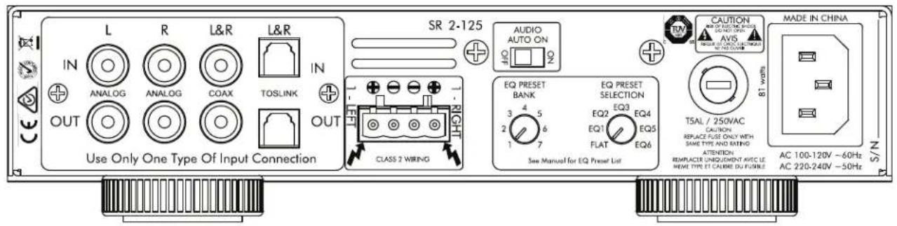
text_image
SR 2-125 AUDIO AUTO ON EQU PRESET BANK EQ PRESET SELECTION EQ2 EQ3 EQ4 EQ1 EQ5 FLAT EQ6 See Manual for EQ Preset List CAUTION AVIS BEAMER FOR CHINA ELECTRICAL POWER COVER MADE IN CHINA AC 100-120V ~60Hz AC 220-240V ~50Hz Use Only One Type Of Input Connection IN ANALOG ANALOG COAX TOSLINK IN OUT CLASS 2 WIRING S/NPRODUCT FEATURES
FIGURE 2: SR 2-125 TWO-CHANNEL AMPLIFIER FRONT PANEL
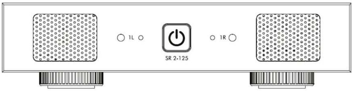
text_image
1L SR 2-125 1RSR 2-125 FRONT PANEL
- Illuminated Power Button
- Power, Active & Protection Indicator LED
- Recessed Volume Level Control
FIGURE 3: SR 2-125 TWO-CHANNEL AMPLIFIER REAR PANEL
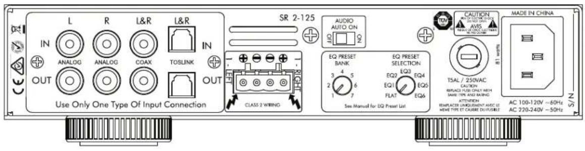
text_image
L R L&R L&R IN ANALOG ANALOG COAX TOSLINK IN OUT Use Only One Type Of Input Connection SR 2-125 AUDIO AUTO ON CLASS 2 WIRING EQ PRESET BANK EQ PRESET SELECTION EQ2 EQ3 EQ4 EQ1 EQ5 FLAT EQ6 See Manual for EQ Press List CAUTION AVIS TALE / 250VAC CAUTION REPLACEMENT UNIQUISMENT NAME OF MIME TYPE ET CAUBE DUTTURES MADE IN CHINA AC 100-120V ~60Hz AC 220-240V ~50Hz N/SSR 2-125 REAR PANEL
- L/R Line In/Coax/Toslink
- Speaker Block Connector
- Audio Auto On/Off Switch
- EQ Preset Bank
- EQ Preset Selection
- AC Fuse Holder
- Power Cord Connection
text_image
1L O SR 3-125 1RFIGURE 4: SR 2-125 AMPLIFIER FRONT PANEL VIEW FIGURE
text_image
L R LEA LEB IN OUT AIN 3.125 OUT AIN 3.125 OUT AIN 3.125 OUT AIN 3.125 OUT AIN 3.125 OUT AIN 3.125 OUT AIN 3.125 OUT AIN 3.125 OUT AIN 3.125 OUT AIN 3.125 OUT AIN 3.120 OUT AIN 3.120 OUT AIN 3.120 OUT AIN 3.120 OUT AIN 3.120 OUT AIN 3.120 OUT AIN 3.120 OUT AIN 3.120 OUT AIN 3.120 OUT AIN 3.120 OUT AIN 3.125 OUT AIN 3.125 OUT AIN 3.125 OUT AIN 3.125 OUT AIN 3.125 OUT AIN 3.125 OUT AIN 3.125 OUT AIN 3.125 OUT5: SR 2-125 AMPLIFIER REAR PANEL VIEW
Front Panel
Power Switch
The power switch turns the amplifier on and off.
When the power switch is lit solid white, the amplifier has power, is turned ON and ready to operate.
When the power switch is slightly dimmed the amplifier is in standby mode.
When the power switch is blinking white, the amplifier power supply is in thermal protection. The channel LEDs will also light red when the power supply is in thermal protect mode.
NOTE: Upon initial power up there will be an approximately 9-12 second boot up cycle. This is normal.
Input/Output Lights
When each channel is active, the LED will light green as long as a signal is present.
When the LED blinks red, this is an indication that the channel is being overdriven.
When the LED lights are solid red this is an indication the amplifier is in protect mode. While in protect mode the LED lights will periodically light green to retest the output to determine if the short has been removed. Protect mode could be caused by a short in the wire, overheating of the amplifier or possibly an internal problem with the amplifier.
NOTE: WHEN ANY OF THE LEDS ARE LIT RED TURN THE AMPLIFIER OFF IMMEDIATELY. DETERMINE THE CAUSE OF THE PROBLEM BEFORE TURNING THE AMPLIFIER ON.
Volume Level Control
Each channel on the amplifier has front panel recessed volume controls that will adjust the output and turn on volume. The amplifier must be powered on to make these adjustments.
Rear Panel
Inputs
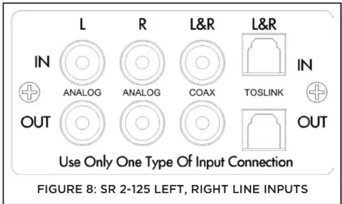
The SR 2-125 amplifier has analog, coax and toslink LINE INPUTS and loop OUTPUTS.
The analog loop outputs are non buffered. The maximum number of amplifiers that can be looped together will depend on the output capability of your source component. The digital outputs are buffered and can support multiple amplifiers. Only one output can be used at a time.
Speaker Connections
The removable block connectors used on the SR 2-125 amplifiers will accept up to 12 gauge wire.
Follow the connection layout on the rear panel of the amplifier. Make sure no bare wires come in contact with the amplifier chassis.
AC Fuse Holder
To replace the fuse, unplug the power cord from the Power Cord Connector and use a screwdriver to remove the fuse holder. SR 2-125 - 5 amp AC (T5-AL)
CAUTION: FOR CONTINUED PROTECTION AGAINST FIRE, REPLACE THE FUSE WITH ONLY THE SAME TYPE AND RATING.
Power Cord
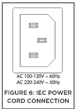
The SR 2-125 amplifiers feature removable IEC power connectors. Plug the female end of the power cord into the Power Cord Connector on the amplifier rear panel and plug the male end into a grounded wall socket.
DO NOT plug the amplifier's power cord into a convenience outlet on any other audio or video component. If you need to use an extension cord, use only a heavy duty (14-GAUGE OR LARGER) extension cord to avoid starving the amplifier of the current necessary for full operation.
POWERING THE AMPLIFIER
The SR 2-125 features a removable IEC power connector (Figure 6). A 14-gauge EIA standard 120-volt grounded power cable is included with the amplifier.
Each time the amplifier's power cord is initially plugged in and the POWER switch is turned ON, all channel outputs are disconnected for approximately 9-12 seconds and all PROTECTION LEDs will illuminate briefly while the amp boots up.
text_image
AC 100-120V ~ 60Hz AC 220-240V ~ 50Hz FIGURE 6: IEC POWER CORD CONNECTIONIMPORTANT: DO NOT PLUG THE POWER CORD INTO THE WALL OUTLET UNTIL ALL SYSTEM CONNECTIONS HAVE BEEN MADE AND VERIFIED.
Plug the female end of the power cable into the Power Connector on the amplifier's rear panel and plug the male end directly into a grounded 15 amp or 20 amp wall outlet.
IMPORTANT: DO NOT PLUG THE AMPLIFIER'S POWER CORD INTO A CONVENIENCE OUTLET ON ANY OTHER AUDIO OR VIDEO COMPONENT.
If the electrical service is subject to frequent sags, spikes, or brownouts, a power conditioner designed for use with high fidelity equipment should be employed to protect the amplifier.
CAUTION: FOR CONTINUED PROTECTION AGAINST FIRE, REPLACE THE FUSE WITH ONLY THE SAME TYPE AND RATING.
Source Connections/Selection SR 2-125
There are two options when connecting audio inputs to the SR 2-125 amplifier (see Figure 8):
Primary Line Inputs 1-L, 1-R - Use these inputs for analog audio source.
Primary Line Coax Inputs L&R - Use these inputs for coax audio source.
Primary Line Toslink Inputs L&R - Use these inputs for toslink audio source.
text_image
L R L&R L&R IN ANALOG ANALOG COAX TOSLINK IN OUT OUT Use Only One Type Of Input Connection FIGURE 8: SR 2-125 LEFT, RIGHT LINE INPUTSAmplifiers Power Requirements: 15 AMP Breaker 20 AMP Breaker
Model Input Voltage Output Power (sinewave) Draw Watts Qty of Amplifiers Qty of Amplifiers
| SR 2-125 | 100-120V AC | Full Power All Channels @ 8 ohms | 311.5 | 4 | 6 |
| Full Power All Channels @ 4 ohms | 326 | 4 | 5 | ||
| 1/8 Power All Channels @ 8 ohms | 61.5 | 23 | 31 | ||
| 1/8 Power All Channels @ 4 ohms | 63 | 22 | 30 | ||
| @ Idle | 26.5 | ||||
| @ Standby | 0.3 |
13 AMP Breaker 20 AMP Breaker
Model Input Voltage Output Power (sinewave) Draw Watts Qty of Amplifiers Qty of Amplifiers
| SR 2-125 | 220-240V AC | Full Power All Channels @ 8 ohms | 300 | 4 | 6 |
| Full Power All Channels @ 4 ohms | 314.5 | 4 | 6 | ||
| 1/8 Power All Channels @ 8 ohms | 58.5 | 24 | 32 | ||
| 1/8 Power All Channels @ 4 ohms | 60 | 24 | 32 | ||
| @ Idle | 24 | ||||
| @ Standby | 0.48 |
FIGURE 7: SR 2-125 TWO-CHANNEL AMPLIFIER POWER REQUIREMENTS
Speaker Connections
For the best sound you should use premium speaker wire that complies with fire rating codes. Be sure to check local codes governing wire that may be installed within walls or ceilings. SONANCE amplifiers are stable with any reputable brand of speaker wire or cable. The SR 2-125 amplifiers use speaker block connectors that can accommodate up to 12 gauge wire (see Figure 9).

text_image
1 - LEFT 1 - RIGHT FIGURE 9: SPEAKER CONNECTORSNOTE: ALWAYS CHECK LOCAL BUILDING CODES BEFORE INSTALLING WIRE IN WALLS OR CEILINGS.
Source Connections SR 2-125
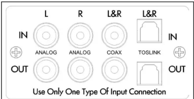
On the left side of the rear panel are the audio inputs for the left and right channels. In addition to the left and right inputs there are also loop outputs for each channel.
The analog loop outputs are non buffered. The maximum number of amplifiers that can be looped together will depend on the output capability of your source component. The digital outputs are buffered and can support multiple amplifiers. The source connected to the LEFT and RIGHT LINE IN Inputs pass through the LEFT and RIGHT LINE Outputs (see Figure 10). This also applies to the Coax and Toslink inputs.
text_image
L R L&R L&R IN ANALOG ANALOG COAX TOSLINK IN OUT OUT Use Only One Type Of Input ConnectionFIGURE 10: SR 2-125 LEFT, RIGHT LINE INPUTS/OUTPUTS
Volume Level Control
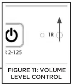
Volume can be controlled from the individual recessed volume level control screws, located on the front panel (see Figure 11). These volume controls balance the desired sound levels per channel.
The volume level controls are set to maximum, fully clockwise, by default.
text_image
2-125 1R FIGURE 11: VOLUME LEVEL CONTROLIMPORTANT: USE CAUTION WHEN SETTING VOLUME LEVELS EITHER ON THE AMPLIFIER OR AN AUDIO SOURCE AS NOT TO OVERDRIVE AND POSSIBLY DAMAGE SPEAKERS. VERIFY ALL SOURCES AS OUTPUT VOLTAGE VARIES FROM DEVICE TO DEVICE.
Protection Circuitry and LEDs
The SR 2-125 amplifiers have a multi-stage protection system to prevent damage to your amplifier and speakers.
SR 2-125 Amplifier Channel Protection
If a channel encounters a short-circuit or an extremely low impedance this will cause the affected channel outputs to automatically mute. The output of the affected channel will remain muted until the fault has been corrected. Only the affected channels output will mute, all other channels will continue to operate normally.
SR 2-125 Amplifier Channel Protection Indication
On the front panel of the SR 2-125 amplifiers are dual color LEDs that illuminate to indicate the current operating status of each amplifier channel.
When the LED blinks red this is an indication that the channel is being overdriven.
When the LED lights are solid red this is an indication the amplifier is in protect mode. While in protect mode the LED lights will periodically light green to retest the output to determine if the short has been removed. Protect mode could be caused by a short in the wire, overheating of the amplifier or possibly an internal problem with the amplifier.
IMPORTANT: ALLOWING THE AMPLIFIER TO OPERATE WITH ONE OR MORE CHANNELS IN PROTECT MODE FOR AN EXTENDED PERIOD OF TIME CAN DAMAGE THE AMPLIFIER.
SR 2-125 Amplifier Power Supply Protection
The amplifier also has protection for the power supply. If the power supply heat sink temperature exceeds the design maximum the protection circuit will activate disconnecting all channel outputs. This is indicated by a blinking light on the front panel power switch.
IMPORTANT: ANY TIME THE PROTECTION CIRCUITS ARE TRIGGERED, UNPLUG THE AMPLIFIER'S POWER CORD FROM THE WALL OUTLET BEFORE TROUBLESHOOTING.
Shelf Mounting
If shelf mounting, attach the four included feet by screwing them into the threaded openings, no tool is required.
Rack Ear Installation SR 2-125
The SR 2-125 amplifier ships with two long rack ears for when the amplifier is to be used alone in a 1U space. Unscrew the four Phillips head screws (M4 x 0.7 pitch x 10mm long) found on each side of the left and right forward section of amplifier. Use these screws to connect the included rack ears to the amplifier (see Figure 12).
SIDE VIEW RIGHT

FRONT VIEW

text_image
2 10 3 12FIGURE 12: RACK EAR INSTALLATION SR 2-125
To place two SR 2-125 amplifiers in a single rack unit order: Rack Mount Bracket for SR 2-125 SKU# 93098 (see Figure 13).
FRONT VIEW

FIGURE 13: RACK MOUNT BRACKET FOR (2) SR 2-125
Amplifier Stacking
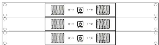
The SR 2-125 amplifier is capable of being directly stacked with the feet removed (see Figure 14) for use in low to moderate output applications. For high-output applications, it is recommended to leave at least 1U space between amplifiers for increased ventilation.
It is not recommended to stack more than three amplifiers high without spacing.
FRONT VIEW
natural_image
Pure electrical circuit lines without any symbolsFIGURE 14: STACKED CONFIGURATION (3) SR 2-125
QUICK SETUP PAGE
Audio - Auto On
Select the Audio Auto On mode you would like to use, either ON or OFF.
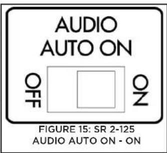
Audio Auto On - ON
When the Audio Auto On switch is in the ON position the amplifier will power off after 15 minutes without an audio signal present on any of the channels. When an audio signal is applied the amplifier will take approximately 9-12 seconds to reproduce audio after going through its power up sequence.
NOTE: THE AUDIO AUTO ON - ON MODE USES THE LEAST AMOUNT OF AC POWER WHEN THE AMPLIFIER IS NOT OPERATING.
text_image
AUDIO AUTO ON OFF OZ FIGURE 15: SR 2-125 AUDIO AUTO ON - ONAudio Auto On - OFF
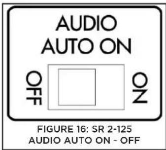
When the Audio Auto On switch is in the OFF position the amplifier will enter Sleep Mode after 15 minutes without an audio signal present on any of the channels. When an audio signal is applied the amplifier will take approximately 2-3 seconds to reproduce audio.
text_image
AUDIO AUTO ON OFF OZ FIGURE 16: SR 2-125 AUDIO AUTO ON - OFFApply DSP Preset
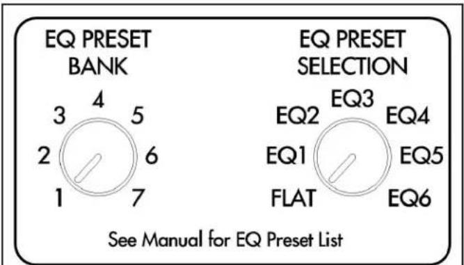
The SR 2-125 amplifier includes pre-programmed DSP presets. These presets are selected utilizing first the EQ Preset Bank dial, followed by the EQ Preset Selection dial (see included DSP Preset Matrix). The first EQ in any bank will be Flat. To select the appropriate preset for your environment please see the included DSP preset Selection Matrix.
text_image
EQ PRESET BANK 3 4 5 2 6 1 7 EQ PRESET SELECTION EQ2 EQ3 EQ4 EQ1 EQ5 FLAT EQ6 See Manual for EQ Preset ListFIGURE 17: SR 2-125 EQ PRESET BANK & EQ PRESET SELECTION
TECHNICAL ASSISTANCE AND SERVICE
The Technical Assistance Department at Sonance is available at (949) 492-7777 to answer any questions concerning the operation and installation of your speakers between the hours of 7:00 AM and 5:00 PM Pacific time, Monday through Friday, except holidays.
In the event your unit should need repair or service, you may return the unit to your authorized dealer or use the following guidelines:
PLEASE KEEP ORIGINAL PACKAGING WHEN POSSIBLE.
- Be prepared to state the model number and / or serial number, date of purchase, and dealer's name and address when calling.
- Contact Sonance directly at (949) 492-7777 or at www.sonance.com. YOU MUST HAVE PRIOR AUTHORIZATION TO RETURN YOUR UNIT.
- If you are returning the product directly to Sonance, call us to obtain a return authorization number before shipping.
- Ship the product via United Parcel Service, Federal Express, or other package delivery service. Please do not use the U.S. Postal Service.
- Include the return authorization number on the shipping label.
- Ship to:
Attn: Quality Assurance Department,
RMA#(include RMA number here)
Sonance
11016 Mulberry Ave.
Suite B
Fontana, CA 92337
TECHNICAL SPECIFICATIONS
SR 2-125 Amplifier
Number of Channels 2 (1 stereo pair)
Power Output - 8 ohms 125 Watts RMS per channel (both channels driven)
Power Output - 4 ohms 200 Watts RMS per channel (both channels driven)
Frequency Response 5Hz - 50kHz, bandwidth limited
Total Harmonic Distortion 0.07% (1kHz, 8 ohms) 0.06% (1kHz, 4 ohms)
Signal to Noise Ratio -100dB (20Hz-20kHz)
Input Gain 29dB
Input Sensitivity 100mV for 1 Watt Output @ 8 ohms
1110mV for 125 Watts Output @ 8 ohms
Input Impedance 20k ohms
Loop Output Impedance 600 ohms
Maximum Analog Input Voltage 2.9V VAC RMS
Power Consumption 120V AC
@8 ohms (sinewave, full power) 311.5 Watts (all channels driven)
@4 ohms (sinewave, full power) 326 Watts (all channels driven)
@8 ohms (sinewave, 1/8 power) 61.5 Watts (all channels driven)
@4 ohms (sinewave, 1/8 power) 63 Watts (all channels driven)
@idle 26.5 Watts
@standby 0.3 Watts
Power Consumption 220V AC
@8 ohms (sinewave, full power) 300 Watts (all channels driven)
@4 ohms (sinewave, full power) 314.5 Watts (all channels driven)
@8 ohms (sinewave, 1/8 power) 58.5 Watts (all channels driven)
@4 ohms (sinewave, 1/8 power) 60 Watts (all channels driven)
@idle 24 Watts
@standby 0.48 Watts
Heat Output
@8 ohms (sinewave, full power) 242 BTU (all channels driven)
@4 ohms (sinewave, full power) 314 BTU (all channels driven)
@8 ohms (sinewave, 1/8 power) 118 BTU (all channels driven)
@4 ohms (sinewave, 1/8 power) 124 BTU (all channels driven)
Operating Voltage 100-120V@60Hz, 220-240V@50Hz
AC Fuse 5A (T5AL - 250V)
Rack Space Requirement 1U - 1/2 Rack Width
Dimensions w/ Feet (W x H x D) 8 5/8" x 2 1/8" x 16 13/16" (219mm x 54mm x 427mm)
Dimensions w/ Rack Ears w/o Feet (W x H x D) 19" x 1 3/4" x 16 13/16" (482mm x 44mm x 427mm)
Shipping Weight 11 lbs (5.0kg)


CAD Files available for download at www.sonance.com
LIMITED TWO (2) YEAR WARRANTY
Sonance warrants to the first end-user purchaser that this Sonance-brand product (“Product”), when purchased from an authorized Sonance Dealer/Distributor, will be free from defective workmanship and materials for the period stated above. Sonance will at its option and expense during the warranty period, either repair the defect or replace the Product with a new or remanufactured Product or a reasonable equivalent.
EXCLUSIONS
TO THE EXTENT PERMITTED BY LAW, THE WARRANTY SET FORTH ABOVE IS IN LIEU OF, AND EXCLUSIVE OF, ALL OTHER WARRANTIES, EXPRESS OR IMPLIED, AND IS THE SOLE AND EXCLUSIVE WARRANTY PROVIDED BY SONANCE. ALL OTHER EXPRESS AND IMPLIED WARRANTIES, INCLUDING THE IMPLIED WARRANTIES OF MERCHANTABILITY, IMPLIED WARRANTY OF FITNESS FOR USE, AND IMPLIED WARRANTY OF FITNESS FOR A PARTICULAR PURPOSE ARE SPECIFICALLY EXCLUDED.
No one is authorized to make or modify any warranties on behalf of Sonance. The warranty stated above is the sole and exclusive remedy and Sonance's performance shall constitute full and final satisfaction of all obligations, liabilities and claims with respect to the Product.
IN ANY EVENT, SONANCE SHALL NOT BE LIABLE FOR CONSEQUENTIAL, INCIDENTAL, ECONOMIC, PROPERTY, BODILY INJURY, OR PERSONAL INJURY DAMAGES ARISING FROM THE PRODUCT, ANY BREACH OF THIS WARRANTY OR OTHERWISE.
This warranty statement gives you specific legal rights, and you may have other rights which vary from state to state. Some states do not allow the exclusion of implied warranties or limitations of remedies, so the above exclusions and limitations may not apply. If your state does not allow disclaimer of implied warranties, the duration of such implied warranties is limited to period of Sonance's express warranty. Your Product Model and Description: DSP 2-125 Amplifier. Warranty Period for this Product: Two (2) years from the date on the original sales receipt or invoice or other satisfactory proof of purchase. Additional Limitations and Exclusions from Warranty Coverage: The warranty described above is non-transferable, applies only to the initial installation of the Product, does not include installation of any repaired or replaced Product, does not include damage to allied or associated equipment which may result for any reason from use with this Product, and does not include labor or parts caused by accident, disaster, negligence, improper installation, misuse (e.g. overdriving the amplifier or speaker, excessive heat, cold or humidity), or from service or repair which has not been authorized by Sonance. Obtaining Authorized Service: To qualify for the warranty, you must contact your authorized Sonance Dealer/Installer or call Sonance Customer Service at (949) 492-7777 within the warranty period, must obtain a return merchandise number (RMA), and must deliver the Product to Sonance shipping prepaid during the warranty period, together with the original sales receipt, or invoice or other satisfactory proof of purchase.
SONANCE
BEYOND SOUND
©2019 Sonance. All rights reserved. Sonance is a registered trademarks of Dana Innovations. Due to continuous product improvement, all features and specifications are subject to change without notice. For the latest Sonance product specification information visit our website: www.sonance.com
SONANCE • 991 Calle Amanecer • San Clemente, CA 92673 USA PHONE: (949) 492-7777 • FAX: (949) 361-5151 • Technical Support: (949) 492-7777 • www.sonance.com 10.24.2019