Visual Performance VP38R - Pregnant SONANCE - Free user manual and instructions
Find the device manual for free Visual Performance VP38R SONANCE in PDF.


| Product Type | In-Ceiling Speaker |
| Brand | Sonance |
| Model | Visual Performance VP38R |
| Driver Configuration | 8-inch polypropylene woofer, 1-inch tweeter |
| Power Handling (RMS) | 80 Watts |
| Frequency Response | 45 Hz - 20 kHz |
| Impedance | 8 Ohms |
| Sensitivity | 88 dB |
| Cutout Diameter | 9.5 inches (241 mm) |
| Overall Diameter | 10.9 inches (277 mm) |
| Depth | 4.5 inches (114 mm) |
| Weight | 5.5 lbs (2.5 kg) |
| Grille | Magnetic, paintable |
| Color | White (paintable) |
| Mounting Type | In-ceiling with dog-leg clamps |
| Installation | Requires ceiling hole, electrical wiring |
| Maintenance | Wipe with dry cloth; do not use liquids |
| Safety | Ensure secure mounting; avoid over-tightening |
| Spare Parts | Contact Sonance customer service |
| Repairability | Service by authorized technician only |
| Warranty | 5 years limited |
Frequently Asked Questions - Visual Performance VP38R SONANCE
User questions about Visual Performance VP38R SONANCE
0 question about this device. Answer the ones you know or ask your own.
Ask a new question about this device
Download the instructions for your Pregnant in PDF format for free! Find your manual Visual Performance VP38R - SONANCE and take your electronic device back in hand. On this page are published all the documents necessary for the use of your device. Visual Performance VP38R by SONANCE.
USER MANUAL Visual Performance VP38R SONANCE
Thank you for purchasing the Sonance Visual Performance VP38R Speakers. When properly installed your new speakers will give you years of entertainment pleasure.
Box Contents
Visual Performance in-ceiling speaker box contains:
(1) Visual Performance speaker
(1) Paintable grille
(1) Mounting cutout template
Speaker Placement - Spacing
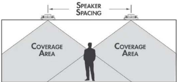
The VP38R speakers have very wide dispersion due to the small diameter of the woofer and tweeter used in the speaker.
This wide dispersion allows the speakers to be placed from 6'-10' (1.8-3.0 meters) apart center to center in a typical 8'-9' (2.5-2.7 meter) height ceiling.
As the ceiling height increases it is possible to separate the speakers farther following the chart below.
flowchart
graph TD
    A["Speaker Spacing"] --> B["Coverage Area"]
    C["Speaker Spacing"] --> D["Coverage Area"]
    style A fill:#f9f,stroke:#333
    style C fill:#f9f,stroke:#333
    style B fill:#ccc,stroke:#333
    style D fill:#ccc,stroke:#333
    note1["Speaker Spacing"] -.-> A
    note2["Speaker Spacing"] -.-> C
    note3["Speaker Spacing"] -.-> D
SPEAKER SPACING (IN FEET) FOR A DISTRIBUTED AUDIO SYSTEM
| STANDING LISTENER | SEATED LISTENER | |
| 8-FOOT CEILING | 5.7' (1.7m) Apart | 9.5' (2.9m) Apart |
| 10-FOOT CEILING | 9.7' (3.0m) Apart | 13.5' (4.1m) Apart |
| 12-FOOT CEILING | 13.7' (4.2m) Apart | 17.5' (5.3m) Apart |
| 14-FOOT CEILING | 17.7' (5.4m) Apart | 21.5' (6.6m) Apart |
Speaker Placement – Sound field
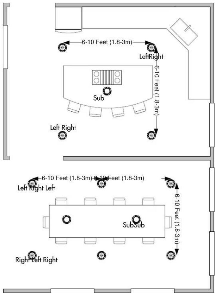
To maximize the sound field created by the VP38R system we suggest connecting the speakers using an alternating left / right pattern as shown in the floorplan to the right.
Using this connection method is very important in rooms without a defined listening position or where multiple people will listen at the same time.
With the speakers connected this way no matter where you are in the room you are more likely to hear a true stereo signal.

Speaker Placement - Examples
When placed as shown in the examples below the VP38R speaker will provide even coverage over a large area.
Kitchen
The kitchen floorplan below illustrates an ideal installation of a four VP38R satellite and one BPS6 subwoofer system.
In this floorplan we have placed the satellites in the high traffic areas and the subwoofer over the island.
Dining Room
In the floorplan above we have shown a typical dining room with six VP38R satellites and two BPS6 subwoofers.
Please note the location of the subwoofers at the center of the array of VP38R speakers. Keeping the subwoofers in close proximity to the satellites will allow a seamless transition from satellite to subwoofer.
Note the alternating left and right speakers for maximum sound field creation.
Wiring
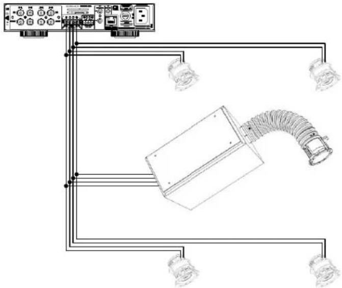
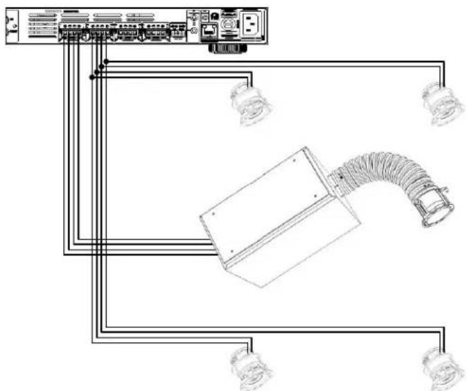
When wiring a DOS system (VP38R & BPS6) you have two options for connecting the speakers to the amplifier.
Wiring - 2 Channel Amplifier
In a system with four VP38R satellites and one BPS6 subwoofer all speakers can be connected to a two channel amplifier.
This connection is possible using the high pass filter on the VP38R satellite and the built in crossover in the BPS6 subwoofer.
natural_image
Pure electrical circuit lines without any symbolsWiring - Multi-Channel Amplifier
The alternative connection method is to dedicate two amplifier channels to the four VP38R satellites then connect the BPS6 subwoofer to a dedicated pair of amplifier channels.
Using this connection method allows you to adjust the level of the satellites and subwoofers independently.
natural_image
Pure electrical circuit lines without any symbolsBefore Installation
-
Determine the location for the speaker (see Speaker Placement on page 1).
-
Perform an obstruction survey using a stud finder to be certain that there are no studs, conduit, pipes, heating, ducts, pocket doors or air returns in the ceiling cavity that will interfere with the speaker. If you are unsure about obstructions, drill a small hole in the center of the outline and insert a coat hanger wire into the hole to feel around for possible obstructions.
-
Cut the mounting hole using a 4" (102mm) hole saw, and run the speaker wires from the mounting hole to the amplifier location. NOTE: CONSULT LOCAL BUILDING CODES BEFORE RUNNING SPEAKER WIRES THROUGH CEILINGS.
High Pass Filter Switch
-
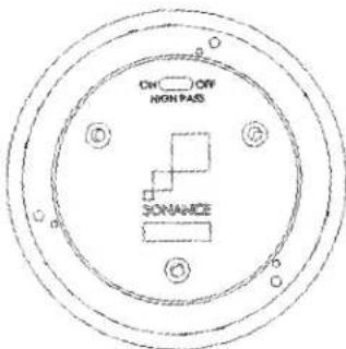
The high pass filter switch is located on the back of the speaker. The setting for this switch should be determined before you start installing the VP38R speaker.
-
The default position is ON. In the ON position the high pass filter will limit the quantity of low bass sent to the VP38R speaker. The high pass filter is necessary to allow a smooth transition from the VP38R to the BPS6 subwoofer.
-
If the VP38R will be used without a subwoofer the high pass filter switch should be set in the OFF position.
-
If the VP38R will be used with a Sonance DSP series amplifier the high pass filter switch should be set in the OFF position. The high pass filter will be applied in the DSP preset.
Two Piece Toggle Foot
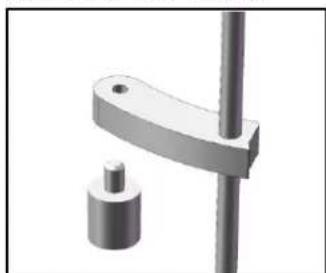
Sonance Visual Performance Speakers feature integral two piece Roto-Lock mounting system for quick mounting directly into existing ceilings.
- The Roto-Lock system can accommodate a ceiling material thickness of 1/4" (6mm) to 1-7/8" (48mm).
With the toggle foot cap removed the system can accommodate a ceiling material thickness of 7/16" (12mm) to 2-1/8" (54mm).
- When installing into double drywall or other thicker ceiling materials, you may need to remove part of the two-piece toggle feet. Unscrew the toggle foot cap from the toggle foot.
natural_image
Mechanical clamp device with a cylindrical base and vertical rod (no text or symbols visible)Wire Connection
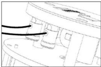
- Strip 1/4" - 1/2" (6mm - 12mm) of insulation from each speaker lead. Twist the strands or tin the exposed wire with solder to ensure that there are no stray strands.
NOTE: Stray strands that touch each other can cause a short-circuit that can damage the amplifier!
natural_image
Technical line drawing of a mechanical component with no visible text or symbols- The speaker's terminals are spring-loaded. Push the top of each terminal down to open the connector and insert the exposed wires into the holes in the spring terminals. The speaker's positive spring terminal is labeled with a red dot; the negative spring terminal is labeled with a black dot. Double check that you connected amplifier "+" to speaker "+" and amplifier "-" to speaker "-"
Installation
-
Make sure all the Roto-Lock toggle feet are retracted so that they are tucked within the mounting hole's border.
-
Insert the speaker into the hole in the ceiling.
-
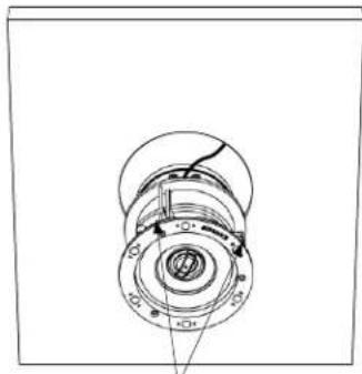
Tighten the screws on the front of the speaker baffle. The Roto-Lock toggle feet will automatically rotate into position and begin clamping the speaker. When you notice resistance on the screws the speaker has been clamped successfully.
natural_image
Technical line drawing of a mechanical assembly with concentric rings and mounting holes (no text or symbols)Roto-Lock Clamps (retracted)
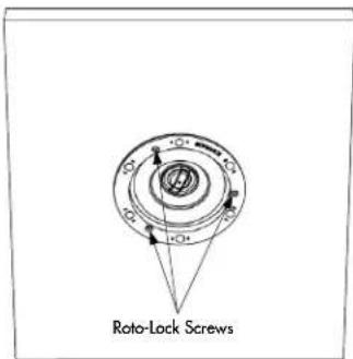
IMPORTANT: ALWAYS USE LOW TORQUE SETTINGS; DO NOT OVER TIGHTEN!
NOTE: Adjust the tension of the Roto-Lock clamps so that the speaker frame is flat. This will help ensure the grille contacts the ceiling all the way around the speaker for a proper fit.
- The micro-trim grille is held in place by several small, powerful magnets on the speaker frame. Place the grille against the speaker and the magnets will hold it firmly in place. When properly installed, the grille trim should make contact with the wall all the way around the speaker.
Square Adapter Instructions
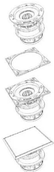
- The VPSQ Square Adapter slides on through the rear of the round speaker prior to installation.
- Place speaker through the round ceiling cut-out, loosely tighten the Roto-Lock toggle feet, then align the Square Adapter on the speaker to the correct symmetry.
- Once the Square Adapter is straight in line with other speakers, lighting, and/or HVAC ceiling fixtures, secure the Roto-Lock toggle feet at a low torque setting
- Attach the magnetic grille.
NOTE: The Square Adapter includes small screw holes that can be used to tighten the adapter to keep the corners flush to the ceiling in case of heavy textures.
Note: #6 drywall screws and drywall anchors not included. Screws will not always be necessary for every installation.
natural_image
Exploded view diagram of a mechanical assembly showing top, front, side, and cross-sectional views (no text or labels)LIMITED LIFETIME WARRANTY
Sonance warrants to the first end-user purchaser that this Sonance-brand product ("Product"), when purchased from an authorized Sonance Dealer/Distributor, will be free from defective workmanship and materials for the life of the Product, except for the grille, which is warranted for five (5) years. Sonance will at its option and expense either repair the defect or replace the Product with a new or remanufactured Product or a reasonable equivalent.
EXCLUSIONS
TO THE EXTENT PERMITTED BY LAW, THE WARRANTY SET FORTH ABOVE IS IN LIEU OF, AND EXCLUSIVE OF, ALL OTHER WARRANTIES, EXPRESS OR IMPLIED, AND IS THE SOLE AND EXCLUSIVE WARRANTY PROVIDED BY SONANCE. ALL OTHER EXPRESS AND IMPLIED WARRANTIES, INCLUDING THE IMPLIED WARRANTIES OF MERCHANTABILITY, IMPLIED WARRANTY OF FITNESS FOR USE, AND IMPLIED WARRANTY OF FITNESS FOR A PARTICULAR PURPOSE ARE SPECIFICALLY EXCLUDED.
No one is authorized to make or modify any warranties on behalf of Sonance. The warranty stated above is the sole and exclusive remedy and Sonance's performance shall constitute full and final satisfaction of all obligations, liabilities and claims with respect to the Product.
IN ANY EVENT, SONANCE SHALL NOT BE LIABLE FOR CONSEQUENTIAL, INCIDENTAL, ECONOMIC, PROPERTY, BODILY INJURY, OR PERSONAL INJURY DAMAGES ARISING FROM THE PRODUCT, ANY BREACH OF THIS WARRANTY OR OTHERWISE.
This warranty statement gives you specific legal rights, and you may have other rights which vary from state to state. Some states do not allow the exclusion of implied warranties or limitations of remedies, so the above exclusions and limitations may not apply. If your state does not allow disclaimer of implied warranties, the duration of such implied warranties is limited to period of Sonance's express warranty.
Your Product Model and Description: Sonance Visual Performance VP38R loudspeaker
Additional Limitations and Exclusions from Warranty Coverage: The warranty described above is non-transferable, applies only to the initial installation of the Product, does not include installation of any repaired or replaced Product, does not include damage to allied or associated equipment which may result for any reason from use with this Product, and does not include labor or parts caused by accident, disaster, negligence, improper installation, misuse (e.g. overdriving the amplifier or speaker, excessive heat, cold or humidity), or from service or repair which has not been authorized by Sonance.
Obtaining Authorized Service: To qualify for the warranty, you must contact your authorized Sonance Dealer/Installer or call Sonance Customer Service at (949) 492-7777 within the warranty pad, must obtain a return merchandise number (RMA), and must deliver the Product to Sonance shipping prepaid during the warranty period, together with the original sales receipt, or invoice or other satisfactory proof of purchase.

natural_image
Abstract geometric pattern of gray squares arranged diagonally (no text or symbols)SONANCE®
© 2015 Sonance. All rights reserved.
Sonance, Visual Performance and Roto-Lock are registered trademarks of Dana Innovations.
Due to continuous product improvement, all features and specifications are subject to change without notice.
For the latest Sonance product specification information visit our website: www.sonance.com
SONANCE • 991 Calle Amanecer • San Clemente, CA 92673 USA
(949) 492-7777 • FAX: (949) 361-5151 • Technical Support: (949) 492-7777
www.sonance.com
33-7449 06.13.17

- Box Contents
- Speaker Placement - Spacing
- Speaker Placement – Sound field
- Speaker Placement - Examples
- Kitchen
- Dining Room
- Wiring
- Wiring - 2 Channel Amplifier
- Wiring - Multi-Channel Amplifier
- Before Installation
- High Pass Filter Switch
- Two Piece Toggle Foot
- Wire Connection
- Installation
- Square Adapter Instructions
- LIMITED LIFETIME WARRANTY
- EXCLUSIONS
Brand : SONANCE
Model : Visual Performance VP38R
Category : Pregnant