
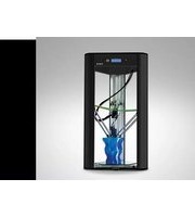
Delta 40100 CLAY - 3D Printer Wasp - Free user manual and instructions
Find the device manual for free Delta 40100 CLAY Wasp in PDF.


| Product Type | 3D Printer for ceramic materials (LDM technology) |
| Brand | Wasp |
| Model | Delta 40100 CLAY |
| Technology | LDM (Liquid Deposited Modeling) |
| Build Volume | Cylindrical: Ø400 mm x 1000 mm |
| Nozzle Diameter (Standard) | 1.2 mm (LDM WASP Extruder) |
| Nozzle Diameter (XL) | 2 mm, 4 mm, 6 mm, 8 mm |
| Layer Resolution | 0.5 mm |
| Axis Precision | 0.2 mm |
| Maximum Printing Speed | 200 mm/s |
| Tank Volume | 5 L |
| Suitable Materials | Porcelain, Gres, Clay, ceramic mixtures |
| Dimensions (L x W x H) | 78 cm x 85 cm x 195 cm (270 cm with tank support) |
| Weight | Approx. 80 kg |
| Power Supply | 220/240 V, 50/60 Hz |
| Power Consumption | 200 W (drivers) |
| Noise Level | < 70 dB(A) |
| Operating Temperature | 20-30 °C |
| Storage Temperature | 0-30 °C |
| Control Interface | LCD display, SD card, USB |
| Supported Slicing Software | Cura, Slic3r, Simplify3D |
| Host Software | Repetier Host, Pronter Face |
| File Formats | .stl, .obj, .gcode |
| Operating Systems | Windows, Mac, Linux |
| Safety Features | Pause button, safety stickers, residual risk warnings |
| Warranty | 12 months (companies), 24 months (individuals) |
| Included Accessories | Getting started guide, SD card, power cable, pipes, tank, tank support with spring, 10 kg material |
Frequently Asked Questions - Delta 40100 CLAY Wasp
Important: Lubricate the threaded bars and handles periodically.
User questions about Delta 40100 CLAY Wasp
0 question about this device. Answer the ones you know or ask your own.
Ask a new question about this device
Download the instructions for your 3D Printer in PDF format for free! Find your manual Delta 40100 CLAY - Wasp and take your electronic device back in hand. On this page are published all the documents necessary for the use of your device. Delta 40100 CLAY by Wasp.
USER MANUAL Delta 40100 CLAY Wasp
MANUAL OF USE AND MAINTANANCE
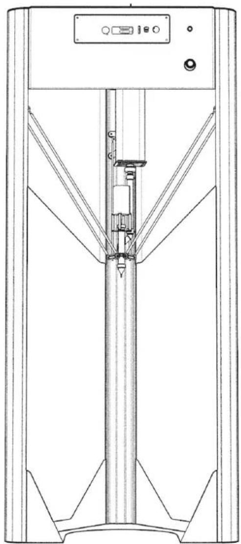
natural_image
Technical line drawing of a vertical mechanical device with mounting flanges and control panel (no text or symbols)CLAY
ORIGINAL INSTRUCTIONS
Discalaimer

IMPORTANT:
We kindly praise to read carefully and comprehend totally the content in this manual of Use and Maintenance.
The missing acknowledgment of the manual can be cause of personal injury, worst quality results or damages to the printer Delta WASP 40100 Clay. Always make sure that the personal using the 3D printer knows and understands the content of the manual in order to the best results from tDelta WASP 40100 Clay.
| 1 First edition - | ||
| Revision Reason for the revision Revision date | ||
No part of this publication may be reproduced, stored in a filing system or transmitted to third parties in any form or by any means, without the Manufacturer having issued a prior written authorization. The Manufacturer reserves the right to make changes to its products at any time and without notice in order to constantly increase the quality, therefore this publication may also be subject to future modifications and updates.
Summary
0 Premises....5
0.1.Aim of the instruction manual 5
0.2. How the read the manual of instructions......6
0.3.Storage of the manual of instructions 6
0.4. Updating the manual of instructions 6
1 General information....7
1.1. Manufacturer identification data....7
1.2. Indentification label .... 7
1.2.1. Position of the label on the printer .... 8
1.3.Testing....8
1.4.Warranty 8
1.5. Declaration of conformity 9
1.6. General safety warnings.... 10
1.6.1. Personal protective equipment....10
1.6.2. Operators for whom the manual is intended ..... 11
1.6.3. Residual risks 11
1.6.4. Safety stickers.... 12
1.7. Glossary and pictograms.... 13
1.7.1. Identification of operating personnel 13
1.7.2. Editorial pictograms.... 14
2 Description of the printer 15
2.1. Control panel 16
2.2. Work area....17
2.3. Technical data.... 18
2.4. Noisiness....19
2.5. Intended use of the printer 19
2.6. Improper use of the printer 19
3 Transport and handling 20
3.1. General warnings.... 20
3.1.1. Delivery of the printer 20
3.2. Unpackaging.... 21
3.3. Content 21
3.4. Lifting and handling of the printer 21
4 Installation....22
4.1.General warnings....22
4.1.1.Placement 22
4.2. Electrical connection 23
5 Preparing to use the printer 24
5.1. General warnings.... 24
5.2.User interface....25
5.2.1.Main board....25
5.2.2. Tune menu....27
5.2.3. Advanced menu (machine not printing) 27
5.2.4. Advanced menu (machine printing) 27
5.3. First start ....
5.4.First start 28
6 First use of the printer 30
6.1.General warnings....30
6.2.Printing bed....31
6.3. First printing layer 31
6.4. Loading of material 32
6.5. First print 33
6.6.Free zeta system 33
6.7. Resurrection system.... 33
7 Ordinary and extraordinary maintenance......34
7.1. General warnings....34
7.2. Ordinary maintenance.... 35
7.2.1. Ball joints 36
7.2.2. Stepper fan.... 36
7.2.3.Sliders 36
7.3. Extraordinary maintenance 36
8 Additional instructions....38
8.1. General warnings.... 38
8.2. Decommissioning and dismantling.... 38
8.3. Instructions for emergency situations 39
INTRODUCTION
Delta WASP Clay line features all the latest technological innovations in the world of digital ceramics developed by WASP.
The Manufacturer declines any responsibility for accidental damages caused by products when non-correctly used.
WASP certifies the use LDM WASP Extruder and LDM WASP Extruder XL with ceramic materials, in case of use of the system with different kind of materials, warranty and support may not be valid anymore.
WARNING
-Read accurately the instructions before the use
-Before any intervention in proximity or inside the work area pause the movements by pushing the yellow bottom on the right side of the frontal panel
-Make sure, before everything is in pressure, that the two caps are both tighten completely until the complete coverage of the tank fillet
-Check periodically that the fillet of the caps and of the tank are not consumed or damaged
-Always keep the fillet on the caps clean in order to avoid the uncorrect closure of the tank
-Periodically put some grease on the fillet of the caps and tank
-Check out the video tutorials at https://www.youtube.com/watch?v=1DjVC5MxJr4
-Do not introduce or lay hands or other parts of the body in proximity of the moving parts
-Keep far from the presence of children
-Do not overcome the 8 bars of pressure
-Do not point the pressurized tank without the cap against people
-Make sure that all the pipes are correctly plugged
-Check the if the fan on the left of the stepper motor is working or not
-Make sure that the extruder is not clogged
-Do not put fingers inside the extruder
-Do not eat the extruded materials
-Make sure that the pipes do not present any deformation
-Verify the waste of the pipes in the points of connection
-Do not replace parts if not original and supplied by Manufacturer
-Only properly formed staff can use the machine
0 PREMISES
0.1. Aim of the instruction manual

IMPORTANT:
Before proceeding with the installing and starting of the printer, the technician, the user, the maintainer and the safety responsible must read and understand the actual manual.
The manual must be considered as a fundamental part of the printer. The correct use and maintenance of the machine depends on the informations contained here.
It contains instructions that must be acknowledged by the personal devoted to the use, maintenance and transport of the machine, supposing the adequate experience, preparation and professional abilitation as well as a psychophysical attitude.
For certain operations it may be necessary to ask for the intervent of personnel who have achieved a specific preparation.
It must always be available for consultation, in copy and by the recipient, on the printer itself or in its immediate vicinity. In the second case the location of the manula must me indicated on the printer clearly.
It is susceptible of updates which, appropriately classified, will be transmitted to the employer in order to update the consultation copy (s).
- The recipient must ensure that the personnel authorized by him to start up, use, maintain and transport the printer have obtained adequate knowledge of the instructions contained in this manual.
- The recipient must check that the maintenance operations, prescribed in the appropriate chapter, are carried out and recorded promptly and effectively.
• We decline any damage or injury caused by the improper use of the printer
• We accept no responsibility for damage to persons or property resulting from improper use and / or omitted or inadequate maintenance. - The recipient has the right to request further information.
In case of loss and/or damage of the present manual is responsibility of the recipient to ask for one or more copies.
0.2. How the read the manual of instructions
This manual is composed by:
COVER WITH PRINTER IDENTIFICATION
By consulting the cover you trace to the printer model covered in the manual and to the printer serial number in your possession.
ANALYTICAL INDEX
By consulting the index it is possible to identify to the chapter and to the paragraph on which all the notes relating to a given topic are reported.
NUMERATION FIGURES
Each figure is numbered progressively, indicating with the first digit the reference chapter and with the second the progressive image (example Fig. 3.4 is the fourth figure of chapter three)
0.3. Storage of the manual of instructions
It is mandatory to keep this manual and all attached documents in an easily accessible place near the printer and known to all users (operators and maintenance personnel).
Operators and maintenance technicians must be able to quickly find and consult the manual in any situation.
The manual is an integral part of the printer for security purposes.
Therefore:
- It must be kept intact (in all its parts);
• It must follow the printer until its disposal (even in case of travel, sale, rental, rent, etc.); - It must be kept up to date and report any changes made to the printer.
0.4. Updating the manual of instructions
This manual must be regularly updated by attaching additional or altered parts.
The sending of any additional parts is the responsibility of the Manufacturer; the user is responsible for the replacement of parts that may be altered as a result of use, making a request directly to the Manufacturer.
1 GENERAL INFORMATION
1.1. Manufacturer identification data
CSP S.r.l.
Viale Zaganelli, 26 - 48024 Massa Lombarda (RA) Italy
Tel. +39 0545 82966
info@3dwasp.com / www.3dwasp.com
1.2. Indentification label
The printer is CE marked and complies with all relevant provisions:
Machinery Directive 2006/42 / EC, EMC Directive 2014/30 / EU and LVD Directive 2014/35 / EU
EN 55022
EN 55024
EN 60204-1
The marking can be identified by means of an identification plate of the Manufacturer as required by the Machinery
Directive. In case of damage, the Recipient must commission a copy.

- Model
- Voltage
- Maximum power
- Year of production
- Serial number
- Advanced settings
1.2.1. Position of the label on the printer

IMPORTANT:
The label of identification of the printer is placed on the back column of the printer near the socket for the supply of the machine
1.3. Testing
The printer is tested directly by the Manufacturer during the phase of mounting and post mounting.
1.4. Warranty
The printers built by CSP S.r.l. are covered by a warranty for a period of 12 months for companies or VAT and 24 months for individuals, according to the specifications set out in the sales contract.
If during the period of validity, defective operations or faults of parts of the printer that fall within the cases indicated in the warranty occur, CSP S.r.l. (after the appropriate checks) will repair or replace the defective parts.
The defective parts under warranty are repaired or replaced free of charge by CSP S.r.l. .
The costs of transport and / or shipment are always charged to the Customer, as well as the return / return travel expenses related to the intervention of the Manufacturer's technicians at the Customer's premises.
The labor costs related to the intervention of the Manufacturer's technicians at the Customer's premises, for the removal of defects under warranty are the responsibility of the Manufacturer, except in cases where the nature of the defect is such that it can be easily removed on site by part of the Customer.
All consumables are excluded from the warranty, possibly supplied by the manufacturer together with the machines.

NOTE:
The guarantee lapses in the following cases:
• In case of default or other contractual non-fulfillment;
- Improper use of the printer
- Failure to comply with the standards and maintenance intervals
- Tampering
- The printer is returned to the Manufacturer in a different packaging from the one supplied at the time of purchase;
- Use of non-original spare parts, ie not supplied directly by the Manufacturer;
- Extraordinary interventions not carried out by personnel not sent by the Manufacturer;
- Any variation and / or non-observance of what is indicated in the technical documents and in this manual entails the forfeiture of the technical and functional guarantees, and release the Manufacturer of the printer from any responsibility.
1.5. Declaration of conformity
Below is the declaration of conformity (FAC-SIMILE) of which the original copy is supplied together with the printer documentation.
1.6. General safety warnings

CAUTION:
Any intervention must be performed on the printer requires particular caution on the part of the operator.

NOTE:
Any intervention on the printer must be carried out in strict compliance with the operational skills (see paragraph 1.7.1 "Identification of Operational Staff"). CSP S.r.l. declines any responsibility in case of non-compliance with these skills.
The purpose of this chapter is to indicate which are the specific points and measures to avoid incurring any kind of accidents, which may be defined as residual risks, which are the minimum essential safety provisions to be maintained, which characteristics must have the personnel assigned to the normal assembly operations and which must be the characteristics of the maintenance personnel.
We are not responsible for unspecified operations, as they are considered strictly pertinent to technical assistance personnel or for operations performed differently from what we described in the documentation presented.
Possible operations on the printer can:
- Mechanics
- Electrical

MECHANICAL NATURE INTERVENTIONS
Any intervention of a mechanical nature must be carried out in strict compliance with the directives required by current safety regulations. It is absolutely forbidden to perform any type of mechanical maintenance intervention on the printer during the operating cycle or in any case with parts of the printer moving.
Every mechanical adjustment operation must be carried out with the printer stopped and only and exclusively by the mechanical maintenance technician, qualified to operate in conditions of protection disconnected (see paragraph 1.7.1 "Identification of the operating personnel").
Maintenance work must only be performed with the printer disconnected from the mains and taking all the safety measures required by current regulations.

ELECTRICAL NATURE INTERVENTIONS
Every electrical adjustment operation must be carried out taking all the safety measures required by current regulations.
1.6.1. Personal protective equipment
It is mandatory to use the specific personal protection devices (PPE) to the current operations made available by the company (in relation to the risk attached to the performance of certain processes), even if not directly concerning the use of the plant.
1.6.2. Operators for whom the manual is intended
The manual is written for:
• The operators involved in using the printer (in the continuation of the manual will be briefly called "users");
- Mechanical maintenance workers: trained and authorized operators for the maintenance of mechanical parts, pneumatic and oil-hydraulic systems;
- Electrician maintenance technicians: trained and authorized operators for the maintenance of electrical and / or electronic parts and systems;
- Qualified technicians (employees of the Manufacturer or authorized service center), special maintenance staff and operations of a complex and / or particular nature.

ATTENTION:
The user must not perform operations reserved for maintenance personnel or qualified technicians. The manufacturer is not liable for damages deriving from failure to observe this prohibition.
1.6.3. Residual risks
Residual risk of injury
Do not put hands inside of the printer while it's working.

CAUTION:
Moving parts: possibility of cutting and crushing

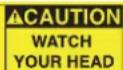
△CAUTION
WATCH OUR HEAD
ATTENTION:
Watch your head, risk of injury.
Residual risk of electrocution

CAUTION:
It is present tension on the superior part of the printer.
Maintenance / Cleaning
Maintenance / cleaning operations must be carried out by trained and authorized personnel. Operations must be performed in a safe stop condition, disconnecting the printer from power sources. Refer to chapter 7 "Ordinary and Extraordinary Maintenance".
1.6.4. Safety stickers
The safety stickers shown below are applied to the printer. Before using the printer, check the integrity of these adhesives and assimilate the instructions. Refer to paragraph 1.7 "Glossary and pictograms". If the meaning is not clearly understood, contact the Manufacturer.

ATTENTION:
The labels and stickers applied to the printer must be replaced before they become illegible. If one or more plates (stickers) are missing or illegible, the operator must not use the printer until the new plates (stickers) have been applied.
Legend:
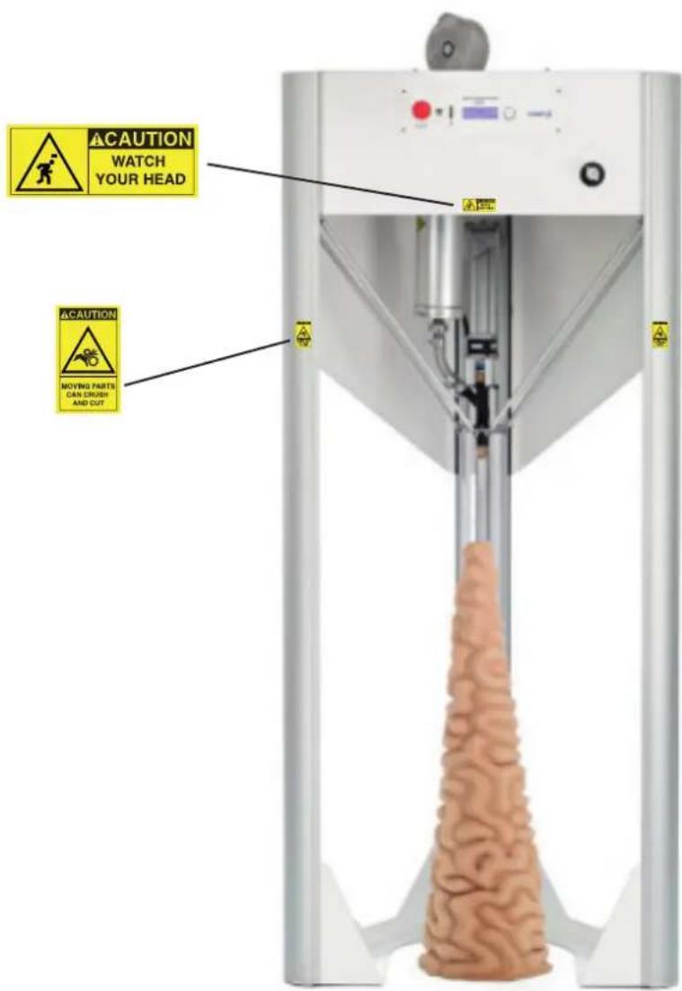
Fig. 1.6.4 - Safety stickers on the printer
1.7. Glossary and pictograms
1.7.1. Identification of operating personnel
The operator responsible for the operation or maintenance of the printer must possess the specific professional requirements for each intended operation.
The operator must be instructed and therefore be aware of the tasks entrusted to him who has responsibility for the job.
Below is a description of the professional profiles for the operators involved in the printer.
User
Qualified personnel, able to perform simple tasks, trained on using the printer.
It supervises the proper functioning of the same and the eventual first intervention in case an alarm condition occurs.
Mechanical maintenance technician
Qualified technician able to conduct the printer under normal conditions, to intervene on the mechanical parts to carry out all the necessary adjustments, maintenance interventions and repairs.
It is not enabled to work on electrical systems in the presence of voltage.
Electrical maintenance engineer
Qualified technician able to conduct the printer in normal conditions; it is in charge of all the electrical interventions of regulation, maintenance and repair. It is able to operate in the presence of voltage inside enclosures and junction boxes
Manufacturer Technician
Qualified technician provided by CSP S.r.l. to carry out operations of a complex nature in particular situations or in any case according to what has been agreed with the user.
1.72 Editorial pictograms
To ensure a deeper knowledge of the printer, the text of this manual is accompanied by indications that complete it, providing additional information, indispensable attention or particularly significant hazards to consider; in this regard, the following notation is used:

DANGER:
Indicates situations or operations in which there is the possibility of causing damage to the printer, to the equipment connected to it.

ENVIRONMENTAL NOTE:
Indicates situations or operations in which there is the possibility of causing damage to the environment.

NOTE:
Indicate the notes, warnings, suggestions and other points on which you want to draw the reader's attention or complete the explanation with further information.
Personal protective equipment (PPE)
The graphic symbols used in this manual are indicated below to indicate the need to wear certain PPE.

PROTECTIVE GAUNTLETS:
Indicates the need to use suitable protective gloves to perform the described operation (possibly dielectrics for carrying out work on the electrical system).

SAFETY SHOES:
Indicates the need to use safety shoes suitable for performing the described operation.

PROTECTIVE WORKWEAR:
Indicates the need to use protective clothing to perform the operation described.

PROTECTIVE HELMET:
Indicates the need to use a safety helmet to perform the operation described.
2 DESCRIPTION OF THE PRINTER
The device described in this manual is a printer intended for 3D printing using fluid-dense material.
The printer consists of an extruder with a screw mounted on a delta robot type structure and a work bed.
The material is put under pressure and pushed towards the extruder where it is dosed in a controlled manner by a screw and poured through a nozzle that deposits very small quantities of material on the work bed.
The material is deposited by the head layer upon layer according to instructions on the file made with the use of a slicing software. It is therefore possible to make any shape and any type of object within the limits of this technology.
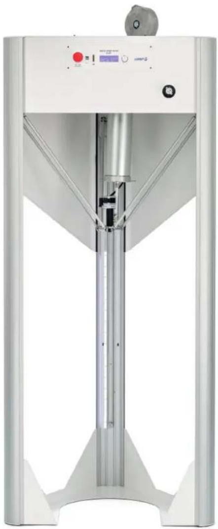
natural_image
Exterior view of a modern industrial machine with control panel and vertical glass structure (no visible text or symbols)Fig. 2 - Printer
2.1. Control panel
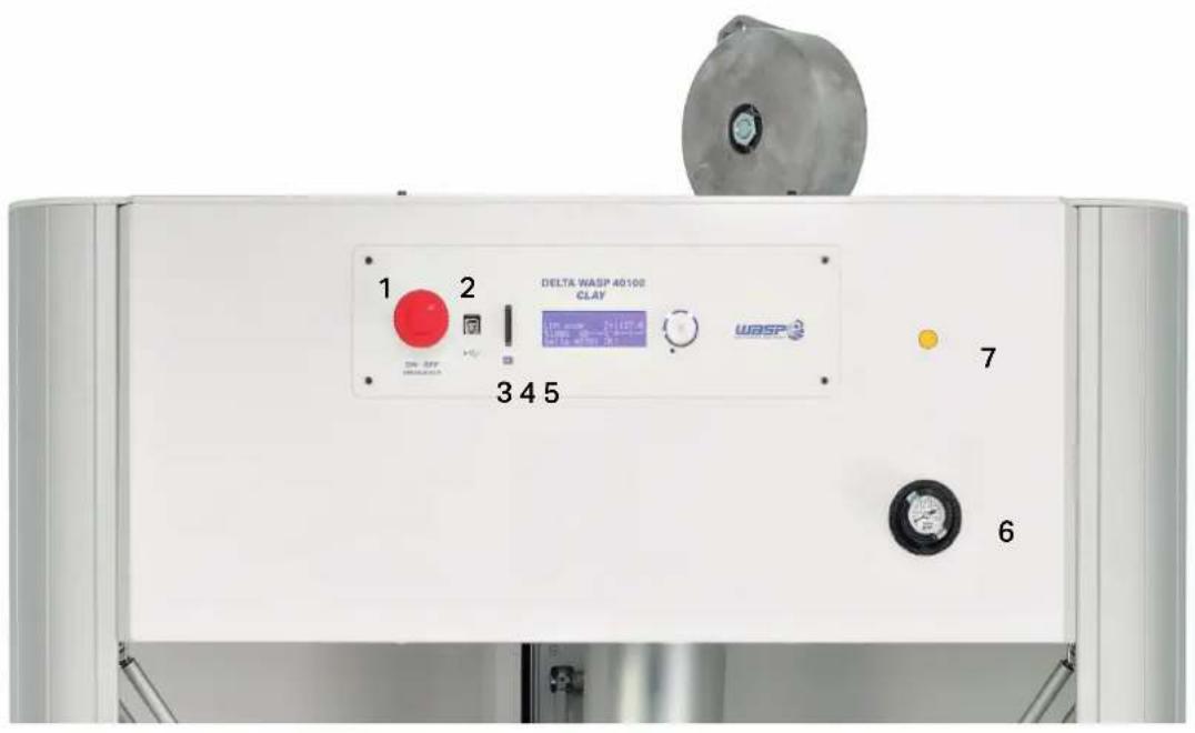
Fig. 2.1 - Control panel
Legend:
- Turn ON/OFF button
- USB door type A
- SD Card door
- LCD display
- Control handle (rotating left/right and it's clickable)
- Pressure regulation
- Pause button
2.2. Work area
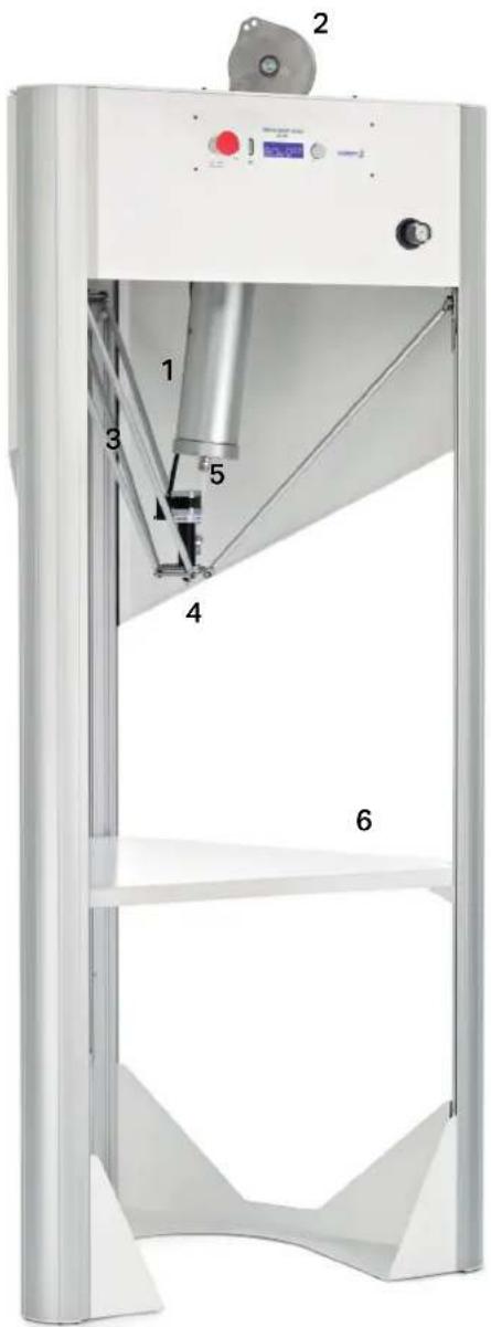
Fig. 2.2 - Work area
Legend:
- Tank
- Tank support
- Double support arm
- Extruder
- Material pipe
- Middle-height plate
2.3. Technical data
All WASP 3D printers are characterized by considerable strength and working precision.
Their mechanics allows for greater precision and stability, guaranteeing greater production speeds.
A further advantage is the possibility of restarting the production of the piece from the point where it should be interrupted for any reason.
| General features | |
| Length 78 cm | |
| Width 85 cm | |
| Height 195 cm (270 cm with tank support) | |
| Approximated weight 80 kg | |
| Noisiness < 70 db (A) | |
| Mechanical features | |
| Frame and cover Metal sheet and aluminium | |
| Print bed Painted metal sheet | |
| Movement Rolling on anodized aluminum slide | |
| Motors Stepper Nema 23 | |
| Electrical features | |
| Input 220/240 V - 50/60 Hz | |
| Absorbed power Drivers: 200W | |
| Use features | |
| Environment of use 20-30 °C | |
| Warehouse | 0-30 °C |
| Estrusore LDM WASP extruder | nozzle diameter: 1.2mm |
| Estrusore LDM WASP extruder XL | nozzle diameter: 2mm, 4mm, 6mm, 8mm |
| 3D printing informations | |
| Technology | LDM |
| Cilindric build area | ∅ 400 x 1000 mm |
| Nozzle diameter standard | LDM WASP Extruder 1.2 mm |
| Layer resolution | 0,5 mm |
| Axis precision | 0,2 mm |
| Maximum speed | 200 mm/s |
| Tank volume | 5 l |
| Suitable materials | Porcelain, Gres, Clay, ceramic mixtures |
| Interface and software | |
| Operative systems | Windows, Mac, Linux |
| Slicing software | Cura, SLic3r, Simplify3D |
| Software interface | Repetier Host, Pronter Face |
| File formats | .stl, .obj, .gcode |
| Interface SD card, LCD display | |
2.4. Noisiness
The noise emitted by the printer only is inferior than 70 dB(A).
The presence of more machines in the same area increases

ATTENTION:
It is the responsibility of the customer to carry out an assessment of the noise risk of his activity as prescribed by the legislation in force in the place where the printer is installed, and to equip the operators with adequate Personal Protective Equipment (such as headphones for hearing protection).
2.5. Intended use of the printer
The printer has been designed and built to create objects with ceramic mixtures. It is possible to use materials such as porcelain, earthenware, stoneware, etc. Any use of the printer with materials other than those supplied will void the warranty and the responsibility of the Manufacturer.
2.6. Improper use of the printer
The following printer uses are prohibited:
- Using the printer to perform operations other than those for which it was designed and constructed described in paragraph 2.6;
- Failure to comply with safety regulations;
• Operation of the printer with procedures other than those described in this manual; - Use components not provided for in the design phase;
- Failure to comply with established maintenance schedules;
- Perform work on the printer that involves the modification of components or parameters that affect the work cycle;
• Alter the extruder calibration; - Use of the printer outside the permitted working temperatures;
• The use without authorization of non-original spare parts or components not approved by the Manufacturer; - The execution of any modification or structural intervention without the Manufacturer's authorization;

NOTE:
• Each of the improper uses or negligence previously listed causes:
- the immediate cancellation of the guarantee stipulated with the Manufacturer at the time of the purchase of the printer;
- the cancellation of the Manufacturer's Responsibility for damages caused to people, things or animals.

ATTENTION
Improper use can damage the printer which consequently can cause dangerous situations for the personnel responsible for its operation and maintenance.
3 TRANSPORT AND HANDLING
3.1. General warnings
The reading of this chapter assumes, in order to use the printer safely, the knowledge of the contents of paragraph 1.6 "General safety warnings".
Furthermore, the specific requirements for safe interaction with the printer, related to this chapter, are detailed in the following paragraphs.

ATTENTION:
The operations related to these activities must be performed by authorized and professionally qualified personnel.

ATTENTION:
During operations, the operator must wear all the necessary Personal Protective Equipment (PPE).

3.1.1. Delivery of the printer
Upon receipt, make sure that:
- The printer has not been damaged during transport;
- Any packaging has not been tampered with consequent removal of parts from the inside;
- The supply corresponds to the order specifications.

NOTE:
If the printer needs to be stored for a certain period of time before installing it, it is recommended to protect it adequately and store it in a suitable environment (with a temperature between 5 °C and 40 °C and relative humidity between 20 % and 60% non-condensing) and protected from atmospheric agents in order to avoid deterioration.

ATTENTION:
During storage, never stack the boxes containing the equipment.
3.2. Unpackaging

ENVIRONMENTAL NOTE:
Once the packaging has been removed from the printer it is recommended to keep it for any requests for assistance from the Manufacturer.
The printer will be delivered in a horizontally oriented wooden box.
After removing the printer from the case, you must place the printer upright.

NOTE:
To perform this procedure it is required the presence of three operators because two will take care of overturning it and the other will keep it steady on one side.
3.3. Content
The printer is supplied with:
- "Getting started" guide
- SD card
- Power cable
- Pipes
- Tank
- Tank support with spring
- Material 10 kgs
3.4. Lifting and handling of the printer

ATTENTION:
The weight of the printer is shown in paragraph 2.4 "Technical data". It is therefore necessary to use the lifting equipment whose expected flow is adequate for the weight to be lifted.

ATTENTION:
As long as the printer is not completely raised, it is advisable to check the correct balance of the same. During lifting, all the area around the printer is considered dangerous.

ATTENTION:
All small equipment that exceeds the weight of 25 kg must be transported with the appropriate equipment, or manually (if not exceeding 50Kg) by two qualified operators.
4 INSTALLATION
4.1. General warnings
The reading of this chapter assumes, in order to use the printer safely, the knowledge of the contents of paragraph 1.6 "General safety warnings".
Furthermore, the specific requirements for safe interaction with the printer, related to this chapter, are detailed in the following paragraphs.

ATTENTION:
The operations related to these activities must be performed by authorized and professionally qualified personnel.

ATTENTION:
During operations, the operator must wear all the necessary Personal Protective Equipment (PPE).


ATTENTION:
A thermal magnetic protection device must be inserted upstream of the system.
4.1.1. Placement
The printer must be installed in a suitable place, ie such as to allow normal operations of the printer, ordinary and extraordinary maintenance.
The installation site must not contain any kind of contaminants, dust, fumes, mists, etc.
It is therefore necessary to prepare the necessary operating space by referring to the dimensions (expressed in mm) given in paragraph 2.4 "Technical data".
The room must also be:
Equipped with the appropriate power supply line;
Installed in environments with brightness equivalent to that expected for industrial environments; as indicated by the regulations in force in the country of destination, with regard to safety in the workplace. Lighting must not cause visual disturbance on the transparent part of the door. The lighting must guarantee a perfect reading of the information given by the display.
The printer must be positioned on a stable and horizontal plane having a capacity suitable for the weight to be supported. Any unevenness must be included in the construction regulations.
The printer must be placed in an environment with foundations that prevent the transmission of environmental vibrations.
Once the printer is positioned, lock the front wheels with the brakes.

ATTENTION:
Do not place the printer near sources of heat, water or other free liquids.
Do not install the printer without the appropriate protections.

NOTE:
A good installation as well as giving greater rigidity to the printer, avoids vibrations and noises.
4.2. Electrical connection

ATTENTION:
The operations related to these activities must be performed by authorized and professionally qualified personnel.

ATTENTION:
It is up to the user to protect the cable mechanically against any crushing or sources of wear according to the type of installation made.

ATTENTION:
The printer must be powered by a 10A socket protected by a magnetothermic set at 30 mA.

NOTE:
All the data concerning the electrical characteristics of the printer can be found in the manual, see paragraph 2.4 "Technical data".
Before connecting the printer's power cord to the electrical outlet, check that the system's power consumption and voltages are suitable.
5 PREPARING TO USE THE PRINTER
5.1. General warnings
The reading of this chapter assumes, in order to use the printer safely, the knowledge of the contents of paragraph 1.6 "General safety warnings".
Furthermore, the specific requirements for safe interaction with the printer, related to this chapter, are detailed in the following paragraphs.

ATTENTION:
The operations related to these activities must be performed by authorized and professionally qualified personnel.

ATTENTION:
During operations, the operator must wear all the necessary Personal Protective Equipment (PPE).

5.2. User interface
5.2.1. Main board
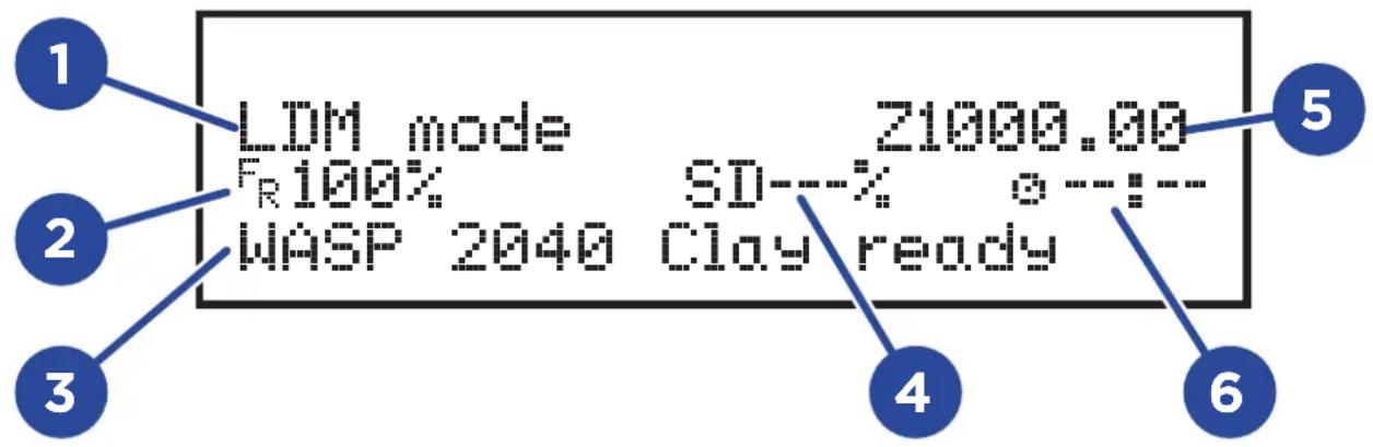
Fig. 5.2.1 - Main board
The main board appears when turning on the printer and when launching the print. It is intended to be the principal tool for the monitoring and control of the printer
Legend:
- Technology
- Feedrate
- Operative information: position, feed, flow, state, autocalibration on/off
- Process percentage
- Z axis position
- Time of work
1. Main menu
Machine not printing
- Main menu: go back to main screen
• Prepare: allows managing various settings of the printer - Advanced: allows managing advanced settings on the printer
- SD Card menu: access files inside inside the SD Card for printing (only with SD card)
- Free zeta system: Allows restarting the print from a certain height (only with SD card)
- Resurrection: in case of blackout allows recovering the print with the automatically saved coordinates (only with SD Card)
- Info: shows the firmware installed on the printer
- Main menu: Goes back to the previous menu
- Disable steppers: disables the motors leaving the printer free to move
• Auto home: for zeroing the axis - Move axis: allows moving the axis X, Y, Z, E of decided lenghts
- Modify height: allows changing the distance between nozzle and printing bed
- Manual leveling: Allows the zeroing of the printer on the three points of regulation
Machine printing
- Main menu: go back to main screen
- Tune: allows managing various settings of the printer
- Pause: allows pausing the print. Click the control handle to resume
- Change material: allows changing the material during the print.
- Stop & save: Allows stopping the print to resume it afterwards. A .ressurr file will be created in the original directory of the file. Select the .resurr file and wait for the start.
- Stop print: Allows stopping definitely the printing of a .gcode
- Info: shows the firmware installed on the printer
5.2.2. Tune menu
- Main menu: go back to main screen
• Speed: allows setting the speed during the print - Flow: allows setting the flow during the print
5.2.3. Advanced menu (machine not printing)
"Advanced" section contains information relative to the management of the printer. To be used only in case of real necessity.
- Main menu: go back to main screen
- Movement: Allows changing the settings relatives to movements and acelleration.
- Autoresurrection: enables the automatic Resurrection system
• Language: allows choosing beetwen English and Italian. - Save in EPROM: saving settings in EPROM
- Load from EPROM: loads all the settings from the EPROM
- Default settings: Resets the system loading default settings
5.2.4. Advanced menu (machine printing)
- Main menu: goes back to home menu
- Movements: allows fixing some values of speed and acceleration
5.4. First start
After having correctly connected the printer to the socket it is necessary to perform some operations in order to allow the printer to work.
Belt-stop clamps
Inside the printer there are three belts necessary for moving the extruder during printing.
To avoid movements of the extruder during transport, clamps are applied on the straps, to be removed before starting the printer.

ATTENTION:
Pay attenention in all the phases and watch your head
To perform the first print, proceed as described here:
- Place the tank support aligned with the two holes on the top of the printer
- Tighten the 2 screws for blocking the tank support
- Turn on the printer with the ON/OFF button on the back column of the printer
- Using the control handle select Menu>Prepare>Load material
- Wait for the extruder to move at middle-height position
- Grab the loaded tank and insert it in the support
- Plug the nylon pipe for the air in the proper connector
- Put the tank to pressure rotating the pressure controller on the left side of the printer
- Extrude some material Menu>Extrude material
- Zero the machine Menu>Prepare>Autohome
- Mesaure the distance with modify height Menu>Prepare>Modify height (advised 0.5 mm between nozzle and bed)
- Perform manual levelling adjusting the 3 screws until the best planarity is reached
- Launch the print from Menu>SD card> file.gcode
6 FIRST USE OF THE PRINTER
6.1. General warnings
The reading of this chapter assumes, in order to use the printer safely, the knowledge of the contents of paragraph 1.6 "General safety warnings".
Furthermore, the specific requirements for safe interaction with the printer, related to this chapter, are detailed in the following paragraphs.

ATTENTION:
The operations related to these activities must be performed by authorized and professionally qualified personnel.

ATTENTION:
Pay particular attention during the various stages of the procedures, it is essential to wear gloves because there is a risk of burns.

ATTENTION:
During operations, the operator must wear all the necessary Personal Protective Equipment (PPE).


NOTE:
Inside the SD card supplied with the printer are provided:
• Free software for creating models to print
- Standard software configurations to be imported into the computer
- Sample file in ".gcode" format to be printed in 3D.
6.2. Printing bed

NOTE: The printer has been designed to print directly on the working surface so that the machine can be moved to proceed with new prints.
NOTE: Another option is printing directly on the bed of the printer. This bed needs to be calibrated on the first use.
To improve the adhesion of the first layers different kinds of beds can be used.
The Manufacturer provides small discs in marine multilayered. Depending on the applications other kinds of beds can be used. The Z axis value must be updated depending on the thickness of the bed.
6.3. First printing layer

NOTE:
To facilitate the adhesion of the printed part maintain a distance of 2 mm between nozzle and bed.

ATTENZIONE:
Moving parts. Possibility of crushing and cutting.
With LDM WASP extruder keep 1mm of distance from the bed
With LDM WASP extruder XL depending on the diameter of the nozzle set as distance half of the diameter from the bed
6.4. Loading of material

NOTE:
WASP provides a mixture to be fixed with water. The amount of water depends on the kind of extruder, nozzle and environmental conditions. Normally it is possible to use the following recipe: porcelaine 95%, water 5%. With the provided machine it is possible to print the majority of the mixtures.
- Lay the mixture on a clean surface.
- Add water (5% water 95% mixture) and mix until total absorption. If the material feels too dry add some water.
- Subdivide the mixture in balls to be loaded inside the internal of the aluminum tank.
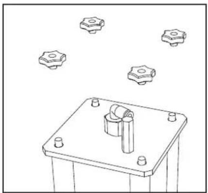
- Untighten the handles on the cap of the aluminum tank (fig.1), then remove the base with the 4 bars (the side without valve)(fig.2).
- Bring the nylon piston to the bottom to load the material.
- Insert and compress the various parts of material (fig.4).
- Place and tighter the base using the handles (fig.5).
natural_image
Technical line drawing of a mechanical assembly with four bolt holes and a central cylindrical component (no text or symbols)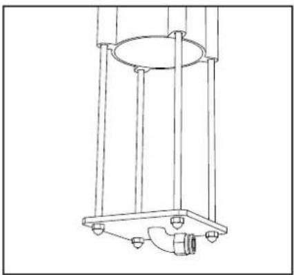
natural_image
Technical line drawing of a mechanical support structure with no visible text or symbols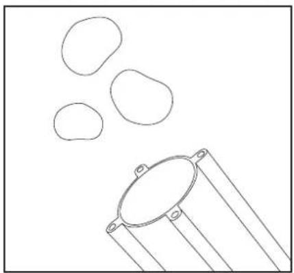
natural_image
Simple line drawing of a container with three oval shapes and a handle, no text or symbols present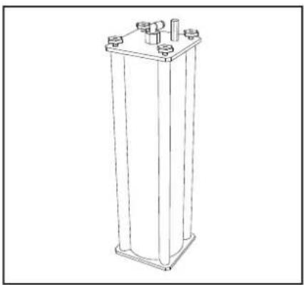
natural_image
Line drawing of a vertical cylindrical structure with four protruding pins (no text or symbols)
NOTE:
Make sure before putting in pressure that the two caps are perfectly touching and fitting on the tank in order to avoid air losses and failures. Make sure that the four handles are tighten well. Lubricate periodically the threaded bars and the internal of the handles.

ATTENTION:
During operations, the operator must wear all the necessary Personal Protective Equipment (PPE).

6.5. First print
To perform the print proceed as described:
- Turn on the compressor to the 8 bars.
- Screw the manometer in clockwise sense until around 5/6 bars (the necessary pressure varies depending on the consistency of the mixture).
- Extruder the material so Menu>Extrude material
- Begin the print selecting: Menu>Sd Card Menu>file.gcode
The print will automatically start and it's just necessary to wait until the end of the process.
As the process is completed the extrude will come back to its zero position.

ATTENTION:
Remove the part only the printing is done

NOTE:
In the case it's necessary to interrupt the print during the printing phase there are two ways to proceed.
- ON/OFF button: by clicking this button on the back of the machine the process will stop in the safest way.
- Pause command: Menu>Pause, ideal for changing material an cleaning the nozzle
6.6. Free zeta system
Free Zeta system can recover a print by starting from a specified height
- Measure the Z value of the last printed layer with: Menu>Prepare>Muovi asse>10,1,0.1>Z axis
- Get very close of the printed object and take note of the Z value, then:
- Menu>Free Zeta System
- Insert Z value
- Select gcode
- Wait for the file to load
The operation (depending on the height and file) can take several minutes.
6.7. Resurrection system
Resurrection System is a system for recovering the prints in case of blackout or sudden lack of current. It automatically saver the coordinates in the point where the print stopped. To use this function select the voice "Resurrection" for the main menu and wait for the printer to restart.
7 ORDINARY AND EXTRAORDINARY MAINTANANCE
7.1. General warnings
The reading of this chapter assumes, for a safe use of the printer, the knowledge of what contained in chapter 1.6 "General safety warnings".
Moreover, the specific prescriptions for interacting in a safe way with the printer, relative to this chapter, are detailed in the next paragraphs.

ATTENTION:
The operations related to these activities must be performed by authorized and professionally qualified personnel.

ATTENTION:
During operations, the operator must wear all the necessary Personal Protective Equipment (PPE).

- Before operating on the printer make sure that this is in safety condition
- At the end of a maintenance intervention remove all the tools and cloths and avoid any stockpile of material
• Always pay attention not to ruin the nozzle and the connection pipes - Do not wear rings, watches, bracelets, chains
• Periodically lubricat with grease the ball joints - Never submerge in water or other liquids the motor on the extruder
- Clean with water and brushes the components of the extruder
- Verify peridically the wear of the connection pipes
- Check that there are no constrictions on the pipes
- Check that there are no obstacles inside the extruder
- Oil the threaded parts before screwing the black handles
- Check periodically that the threaded bars and the internal of the handels are not damaged.
- Clean and lubricate the nylon piston before each use
- Clean all the parts in contact with the mixtures after each use
7.2 Ordinary maintenance
TANK CLEANING
The periodic maintenance and the correct use are fundamental factors to guarantee the functioning, safety and reliability of the machine. The interventions of maintenance are carried out by the mechanical technician that must operate in total accomplishment of the safety warnings contained in this manual.
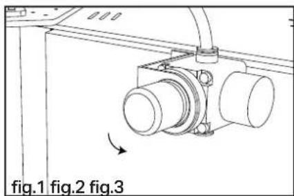
- Reduce to zero the pressure in the tank by turning counterclockwise the controller of the pressure (fig.23).
- Unscrew the handles from CAP A and then remove CAP B (fig.24). To make easier CAP A removal use a flat screwdriver as a lever.
- Place the tank to the bottom.
- With closed fist (o with the help of some tool) push the nylon piston to the external. (fig.25).
- Clean the piston with water and place it back in the tank.
- The remove the residual material that dried inside the TPFE pipe hit it delicately to allow the detachment or push it with a little piston.
natural_image
Technical line drawing of a mechanical assembly with labeled components (no text or symbols beyond labels)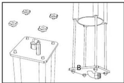
natural_image
Technical line drawing of a mechanical assembly with mounting base and support frame (no text or symbols)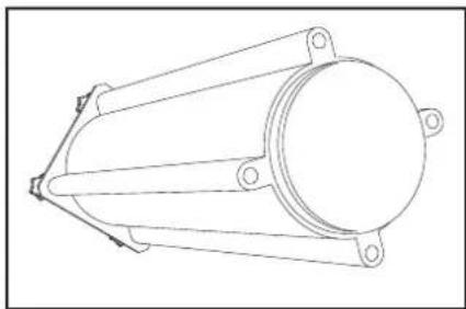
natural_image
Technical line drawing of a mechanical component with flanged ends and central circular feature (no text or symbols)EXTRUDER CLEANING
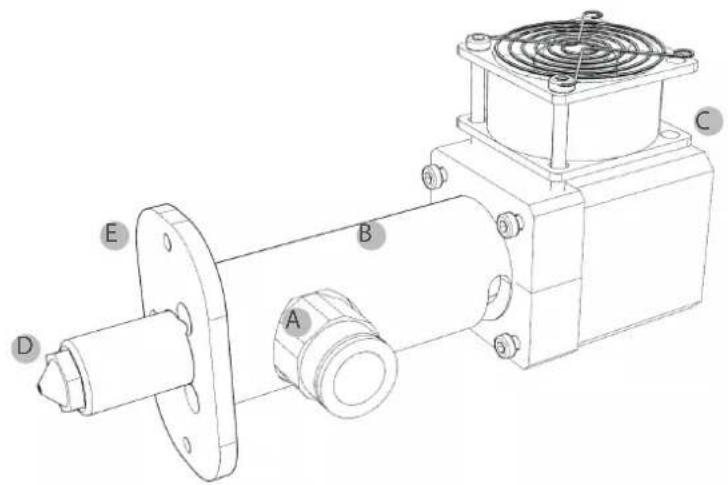
At print finished it is necessary to cover with wet paper the nozzle to re-use it the following day. After around a week the a complete cleaning of the extruder will be necessary, following this procedure:
- remove LDM extruder from the printer
- unscrew pushfit "A" with a 19mm key and clean it with water
- unscrew extruder body "B" from motor "C"
- unscrew the three M3 screws from the aluminum board "E" (not obligated)
• To facilitate the procedure it is advised the use of pipe cleaners
7.2.1. Ball joints
Lubrication
Verify that all the mechanics are moving correctly, especially the ball joints. If they are not working properly lubricate with grease by using a brush.
7.2.2. Stepper fan
Check that the fan on the extruder is working when the machine is turned on
7.2.3. Sliders
Check plays
Verify that there are no plays between sliders and columns. If any play occurs contact the Manufacturer.
7.3. Extraordinary maintenance

ATTENTION:
The operations of extraordinary maintenance must be performed by Technicians formed by the Manufacturer only.
Any of these operations not carried out by a Technicians formed by the Manufacturer can cause the irreversible damage of the machine or of its parts and for this reason it deletes the Warranty
The extraordinary operations are intended as the ones carried out:
With exceptional events as revisions
Sudden stop for the breaking of mechanical or fluid parts
9 ADDITIONAL INSTRUCTIONS
9.1. General warnings
The reading of this chapter assumes, in order to use the printer safely, the knowledge of the contents of paragraph 1.6 "General safety warnings".
Furthermore, the specific requirements for safe interaction with the printer, related to this chapter, are detailed in the following paragraphs.

ATTENTION:
The operations related to these activities must be performed by authorized and professionally qualified personnel.

ATTENTION:
During operations, the operator must wear all the necessary Personal Protective Equipment (PPE).

9.2. Decommissioning and dismantling
In the event that the printer should be taken out of service for a prolonged period while waiting for the dismantling, it is advisable to indicate its presence, preventing unauthorized access to the printer. Before starting the dismantling operations, it is necessary to create around the printer a sufficiently large and orderly space in order to allow all the necessary movements without risk created by the surrounding environment.

ATTENTION:
Observe the requirements imposed by the laws in force and by the authorities in charge of the country in which the demolition takes place.
If the mechanical parts have to be dismantled, keep in mind that they consist of different types of material. The user is therefore obliged to consider disassembling the printer in its parts in order to facilitate a differentiated disposal aimed at recycling the various materials and products, in full compliance with all the regulations in force on the spot.

NOTE:
The dismantling of the printer must be performed by a qualified mechanical maintenance technician.

ATTENTION:
Before carrying out any type of disassembly on the printer, make sure that the power supply is disconnected.

ATTENTION:
Danger crushing hands, falling materials, cuts and abrasions. Obligation to use clothing appropriate to the operation to be performed.

NOTE:
It is absolutely necessary to apply the regulations in force in the country of destination, concerning the disposal of waste, so it is forbidden to disperse in the environment any type of processing residue, oils, etc .. subdividing the dismantled parts by type for a correct separate collection of materials.

NOTE:
Within the European Community, electrical equipment must be disposed of as prescribed by the European Community Directive 2012/19 / EU on waste electrical and electronic equipment (WEEE).

ATTENTION:
The user is obliged to dispose of the equipment in the consortia and collection centers for the treatment and recovery of "WEEE".
9.3. Instructions for emergency situations

ATTENTION:
In the event of a fire, the operator must immediately give the alarm and move away from the area to allow the intervention of trained personnel equipped with suitable protective and operational means.
Electrical parts
In case of fire of electrical parts, intervene with CO2 extinguishers to limit and limit the damages
In general
Use ABC + Nitrogen powder extinguishers to quickly extinguish fires delimited to parts or areas without electrical parts.
NOTE

CSP S.R.L.
Viale Zaganelli, 26 - 48024 Massa Lombarda (RA) Italia
Tel. +39 0545 82966
www.wasproject.it - info@wasproject.it



- Discalaimer
- IMPORTANT:
- Summary
- Premises....5
- General information....7
- Description of the printer 15
- Transport and handling 20
- Installation....22
- Preparing to use the printer 24
- First use of the printer 30
- Ordinary and extraordinary maintenance......34
- Additional instructions....38
- INTRODUCTION
- WARNING
- PREMISES
- Aim of the instruction manual
- How the read the manual of instructions
- COVER WITH PRINTER IDENTIFICATION
- ANALYTICAL INDEX
- NUMERATION FIGURES
- Storage of the manual of instructions
- Therefore:
- Updating the manual of instructions
- GENERAL INFORMATION
- Manufacturer identification data
- Indentification label
- Position of the label on the printer
- Testing
- Warranty
- NOTE:
- Declaration of conformity
- General safety warnings
- CAUTION:
- MECHANICAL NATURE INTERVENTIONS
- ELECTRICAL NATURE INTERVENTIONS
- Personal protective equipment
- Operators for whom the manual is intended
- ATTENTION:
- Residual risks
- Residual risk of injury
- △CAUTION
- Residual risk of electrocution
- Maintenance / Cleaning
- Safety stickers
- Legend:
- Glossary and pictograms
- Identification of operating personnel
- User
- Mechanical maintenance technician
- Electrical maintenance engineer
- Manufacturer Technician
- Editorial pictograms
- DANGER:
- ENVIRONMENTAL NOTE:
- Personal protective equipment (PPE)
- PROTECTIVE GAUNTLETS:
- SAFETY SHOES:
- PROTECTIVE WORKWEAR:
- PROTECTIVE HELMET:
- DESCRIPTION OF THE PRINTER
- Control panel
- Work area
- Technical data
- Noisiness
- Intended use of the printer
- Improper use of the printer
- ATTENTION
- TRANSPORT AND HANDLING
- General warnings
- Delivery of the printer
- Unpackaging
- Content
- Lifting and handling of the printer
- INSTALLATION
- General warnings
- Placement
- Electrical connection
- PREPARING TO USE THE PRINTER
- General warnings
- User interface
- Main board
- Main menu
- Machine not printing
- Machine printing
- Tune menu
- Advanced menu (machine not printing)
- Advanced menu (machine printing)
- First start
- Belt-stop clamps
- FIRST USE OF THE PRINTER
- General warnings
- Printing bed
- First printing layer
- Loading of material
- First print
- Free zeta system
- Resurrection system
- ORDINARY AND EXTRAORDINARY MAINTANANCE
- General warnings
- Ordinary maintenance
- TANK CLEANING
- EXTRUDER CLEANING
- Ball joints
- Lubrication
- Stepper fan
- Sliders
- Check plays
- Extraordinary maintenance
- ADDITIONAL INSTRUCTIONS
- General warnings
- Decommissioning and dismantling
- Instructions for emergency situations
- Electrical parts
- In general
- NOTE
Brand : Wasp
Model : Delta 40100 CLAY
Category : 3D Printer