ProBio-ID - Système de contrôle d'accès sécurisé ZKTeco - Free user manual and instructions
Find the device manual for free ProBio-ID ZKTeco in PDF.


| Product Type | Biometric Access Control System |
| Model | ProBio-ID |
| Brand | ZKTeco |
| Dimensions (W x H x D) | 185 mm x 90 mm x 45 mm |
| Weight | 0.45 kg |
| Power Supply | 12V DC, 3A |
| Display | 2.8-inch TFT color screen |
| Fingerprint Capacity | 3,000 templates |
| Card Capacity | 10,000 cards (optional) |
| Communication | TCP/IP, RS485, USB Host |
| Verification Modes | Fingerprint, PIN, Card, or combination |
| Operating Temperature | 0°C to 45°C |
| Operating Humidity | 20% to 80% |
| Maintenance | Clean optical sensor with soft dry cloth; avoid liquids |
| Security Features | Tamper detection, anti-passback, alarm output |
| Spare Parts Available | Power adapter, mounting bracket, sensor cover |
| Repairability | Modular design for easy replacement of components |
| Certifications | CE, FCC, RoHS |
Frequently Asked Questions - ProBio-ID ZKTeco
User questions about ProBio-ID ZKTeco
0 question about this device. Answer the ones you know or ask your own.
Ask a new question about this device
Download the instructions for your Système de contrôle d'accès sécurisé in PDF format for free! Find your manual ProBio-ID - ZKTeco and take your electronic device back in hand. On this page are published all the documents necessary for the use of your device. ProBio-ID by ZKTeco.
USER MANUAL ProBio-ID ZKTeco
text_image
ProBio ZKT ECO
text_image
ZKTeco ZKBioSecurity 3.0 ✓ Easy to configure and use ✓ Door management ✓ Linkage settings ✓ Real-time monitoring ✓ Maps reports and big reference ✓ SDK evalise to third-party integrationProBio & ProFAC +
ZKBioSecurity 3.0
CONTENT
Safety Precautions....2
On Using Face Recognition Device....3
Device Overview 5
Product Dimensions & Installation....6
Power Connection....7
Ethernet Connection....8
Lock Relay Connection....9
Wiegand Output Connection....11
Standalone Installation 12
Device Operation....13

text_image
ZKTecO ZKBioSecurity 3.0ZKBioSecurity Software
Installation and Setup starts at Page 16
Safety Precautions
The following precautions are to keep users safe and prevent any damage. Please read carefully before installation.


Do not install the device in a place subject to direct sunlight, humidity, dust or soot.

Do not place a magnet near the product. Magnetic objects such as magnets, CRTs, TVs, monitors or speakers may damage the device.

Do not place the device next to heating equipment.

Be careful not to let liquid like water, drinks or chemicals leak inside the device.

Do not let children touch the device without supervision.

Do not drop or damage the device.

Do not disassemble, repair or alter the device.

Do not use the device for any other purpose than specified.

Clean the device often to remove dust on it. In cleaning, do not splash water on the device but clean it with a smooth cloth or towel.
Contact your supplier in case of a problem.
On Using Face Recognition Device
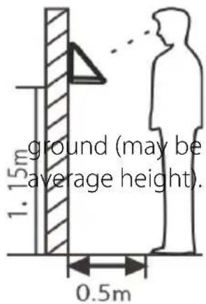
1. Recommended Standing Position
text_image
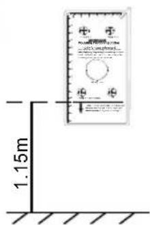
ground (may be average height). 1.15m 0.5mFor user heights between 1.5m to 1.8m, it is recommended to install the device at 1.15m above
a. Recommended Registration and Verification Position

text_image
Enroll 1.15m 0.5m Verify 1.15m 0.3mDuring registration and verification procedures, the position of device should not be changed to prevent deduction in verification preciseness. If it is necessary to move the device, its vertical height should not be changed.
b. Factors Affecting the Preciseness of Verification
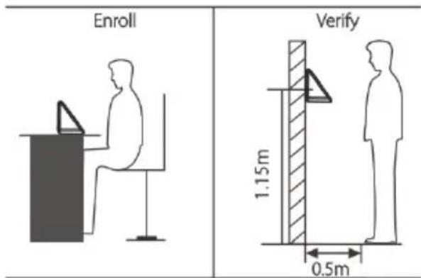
text_image
Enroll Verify 1.15m 0.5mNon-identical registration and verification gestures
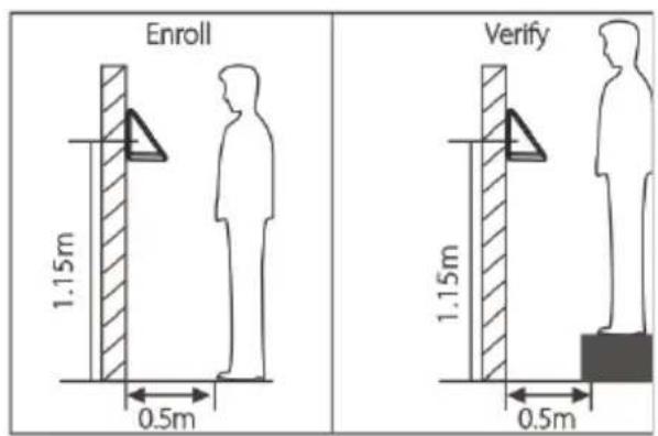
text_image
Enroll 1.15m 0.5m Verify 1.15m 0.5mNon-identical registration and verification height
On Using Face Recognition Device

text_image
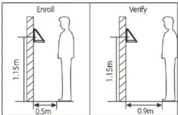
Enroll 1.15m 0.5m Verify 1.15m 0.3mNon-identical registration and verification distances from device
text_image
Enroll 1.15m 0.5m Verify 1.15m 0.9mNon-identical registration and verification distances from device
2. Registration
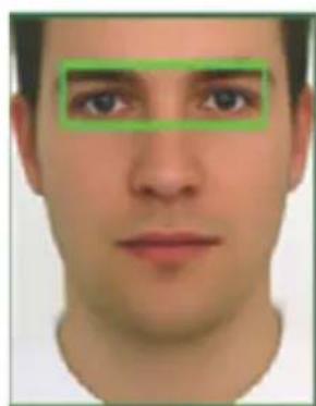
a. During registration, it is required to adjust your upper body to fit your eyes into the green frame on the screen.
b. During verification, it is required to show your face in the center of the screen and fit your face into the green frame in the screen.
natural_image
Frontal view of a human face with green bounding boxes highlighting the eyes and nose (no text or symbols present)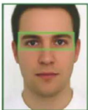
natural_image
Frontal portrait of a man with green bounding boxes highlighting facial features (no text or symbols)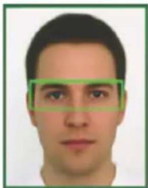
natural_image
Frontal portrait of a man with green bounding boxes highlighting facial features (no text or symbols)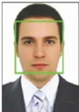
natural_image
Portrait of a man in formal attire with a green bounding box highlighting the face (no text or symbols present)★ Not all products have fingerprint or card function.
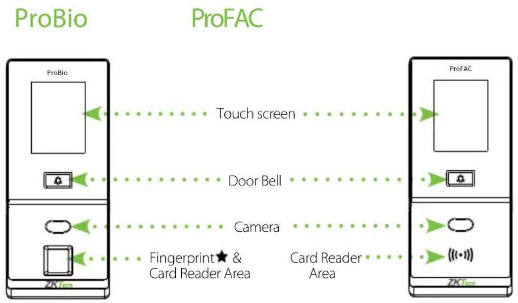
flowchart
graph LR
    A["ProBio"] -->|Touch screen| B["ProFAC"]
    B -->|Door Bell| A
    A -->|Camera| B
    A -->|Fingerprint & Card Reader Area| B
    B -->|Card Reader Area| A
Left side view is common for both the devices
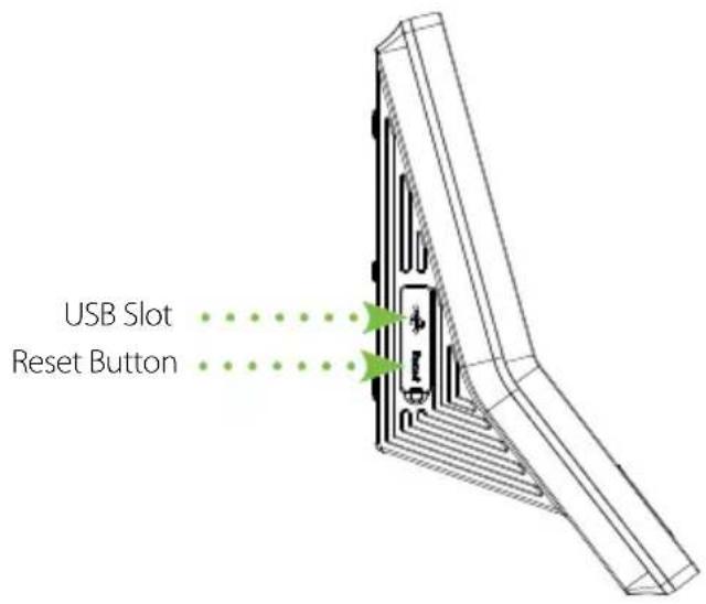
text_image
USB Slot Reset ButtonProduct Dimensions & Installation
Product Dimensions
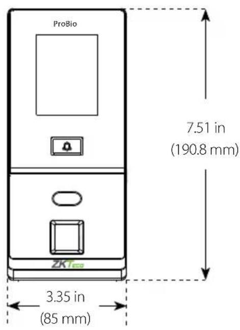
text_image
ProBio 7.51 in (190.8 mm) ZKT 3.35 in (85 mm)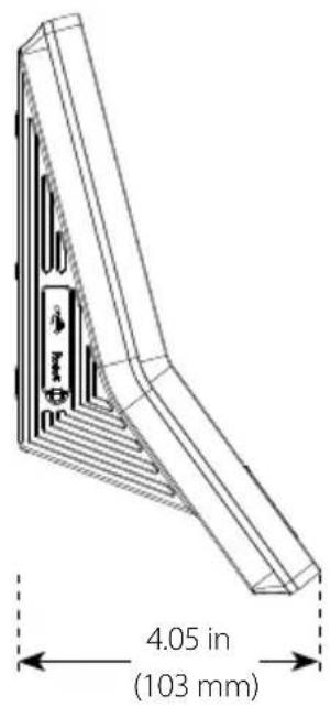
text_image
4.05 in (103 mm)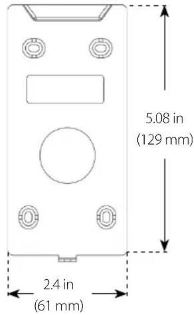
text_image
5.08 in (129 mm) 2.4 in (61 mm)Mounting the Device on the Wall
1
text_image
1.15m Pump Rate Ground LevelPut the mounting template sticker onto the wall, and drill holes according to the mounting paper
2
natural_image
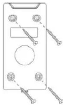
Pure technical line drawing of a rectangular device with screws and a circular button, no text or symbols presentFix the back plate onto the wall using wall mounting screws.
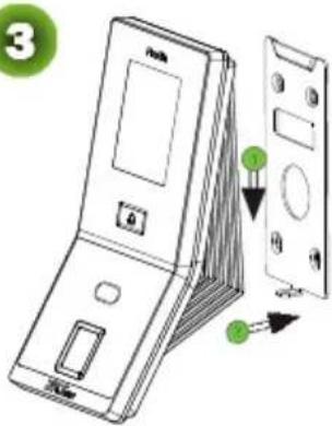
3
text_image
3 1 2Insert the device into the back plate
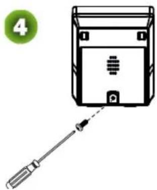
natural_image
Diagram showing a screwdriver inserted into a device housing with a green circle labeled '4' in the corner (no text or symbols on the diagram itself)Use security screws to fasten the device to back plate.
Power Connection
Without UPS
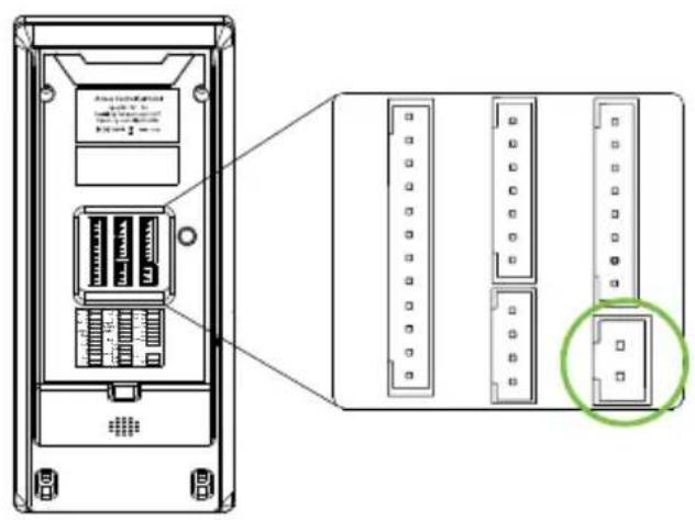
text_image
Technical diagram of a device rear panel with labeled ports and an inset view showing internal structure highlighted in green.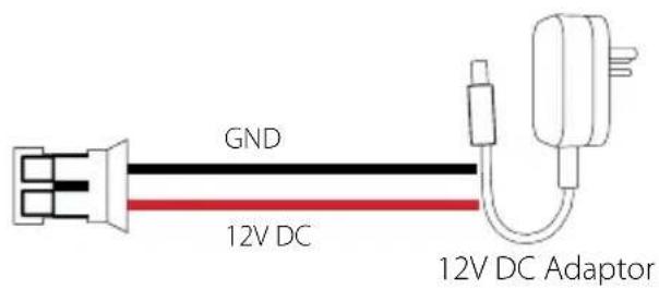
text_image
GND 12V DC 12V DC AdaptorWith UPS (Optional)
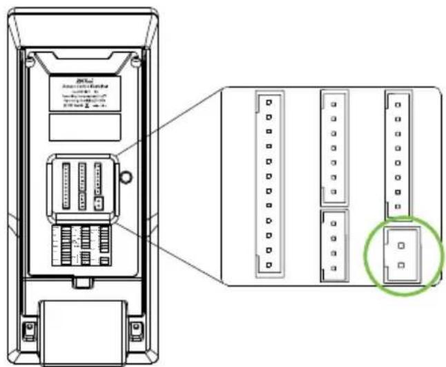
text_image
Technical diagram of a device rear panel with labeled ports and a highlighted component, showing internal structure and connection details.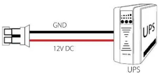
text_image
GND 12V DC UPSRecommended Power Supply
• 12V±10%, at least 500mA (12V/3A is standard).
- To share the power with other devices, use a power supply with higher current ratings.
Ethernet Connection
LAN Connection
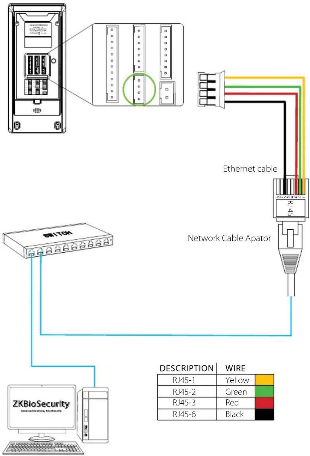
flowchart
graph TD
    A["ZKBioSecurity Advanced Digital Security"] --> B["Switch"]
    B --> C["Network Cable Apator"]
    C --> D["Ethernet cable"]
    D --> E["RJ45"]
    E --> F["Network Cable Apator"]
    F --> G["DESCRIPTION: RJ45-1, RJ45-2, RJ45-3, RJ45-6"]
    G --> H["WIRE: Yellow, Green, Red, Black"]
    style A fill:#f9f,stroke:#333
    style B fill:#ccf,stroke:#333
    style C fill:#cfc,stroke:#333
    style D fill:#fcc,stroke:#333
    style E fill:#cff,stroke:#333
    style F fill:#ffc,stroke:#333
    style G fill:#cfc,stroke:#333
    style H fill:#fcc,stroke:#333
Note: The device can be connected to PC directly by Ethernet cable.
Lock Relay Connection
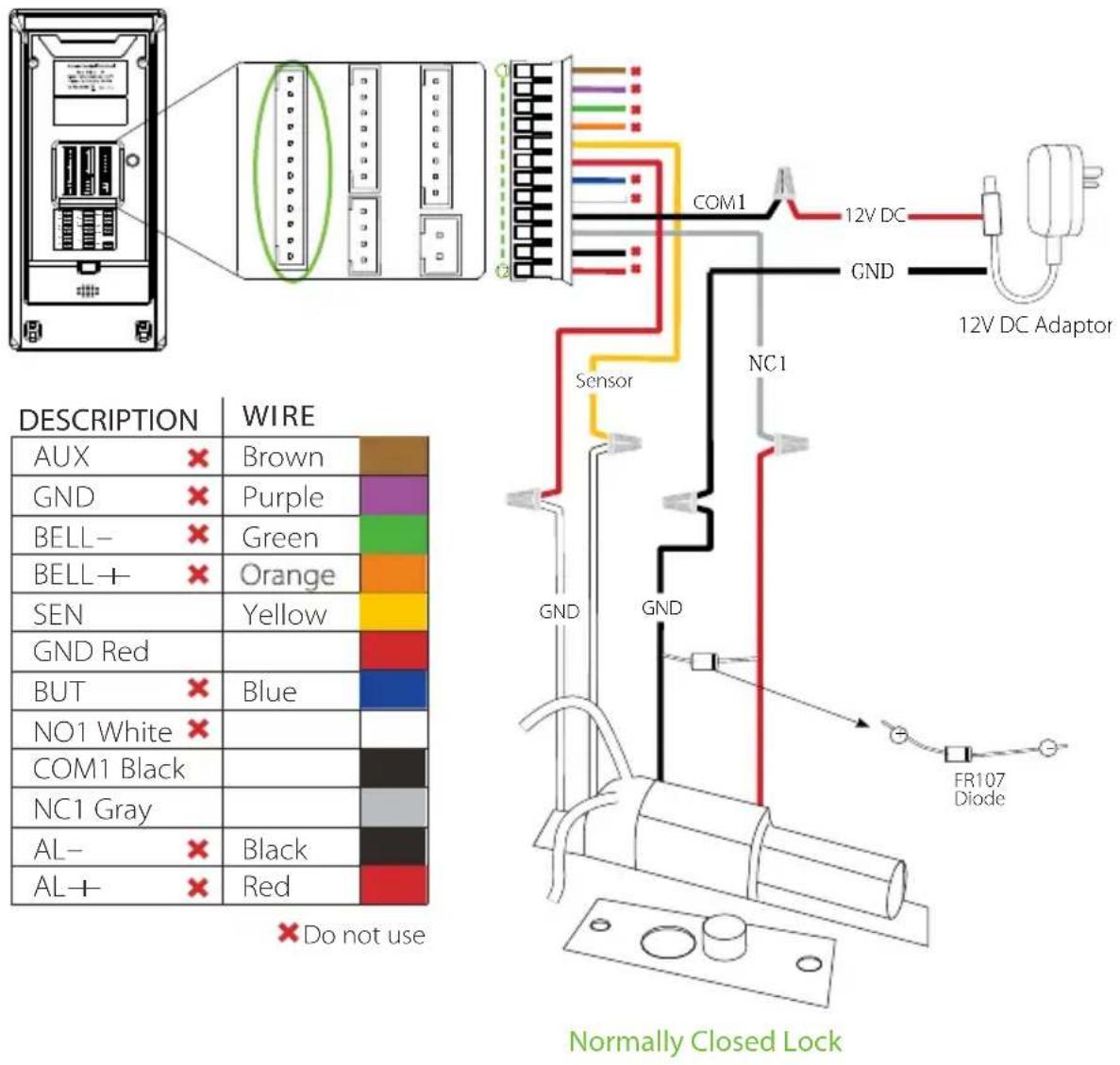
Device Not Sharing Power with the Lock
text_image
DESCRIPTION WIRE AUX × Brown GND × Purple BELL- × Green BELL+ × Orange SEN GND Red BUT × Blue NO1 White × COM1 Black NC1 Gray AL- × Black AL+ × Red × Do not use COM1 12V DC GND 12V DC Adaptor Sensor NC1 GND GND FR107 Diode Normally Closed LockNotes:
-
The system supports NO LOCK and NC LOCK. For example the NO LOCK (normally opened at power on) is connected with 'NO1' and 'COM1' terminals, and the NC LOCK (normally closed at power on) is connected with 'NC1' and 'COM1' terminals.
-
When electrical lock is connected to the Access Control System, you must parallel one FR107 diode (equipped in the package) to prevent the self-inductance EMF from affecting the system.

Do not reverse the polarities.
Lock Relay Connection
Device Sharing Power with the Lock
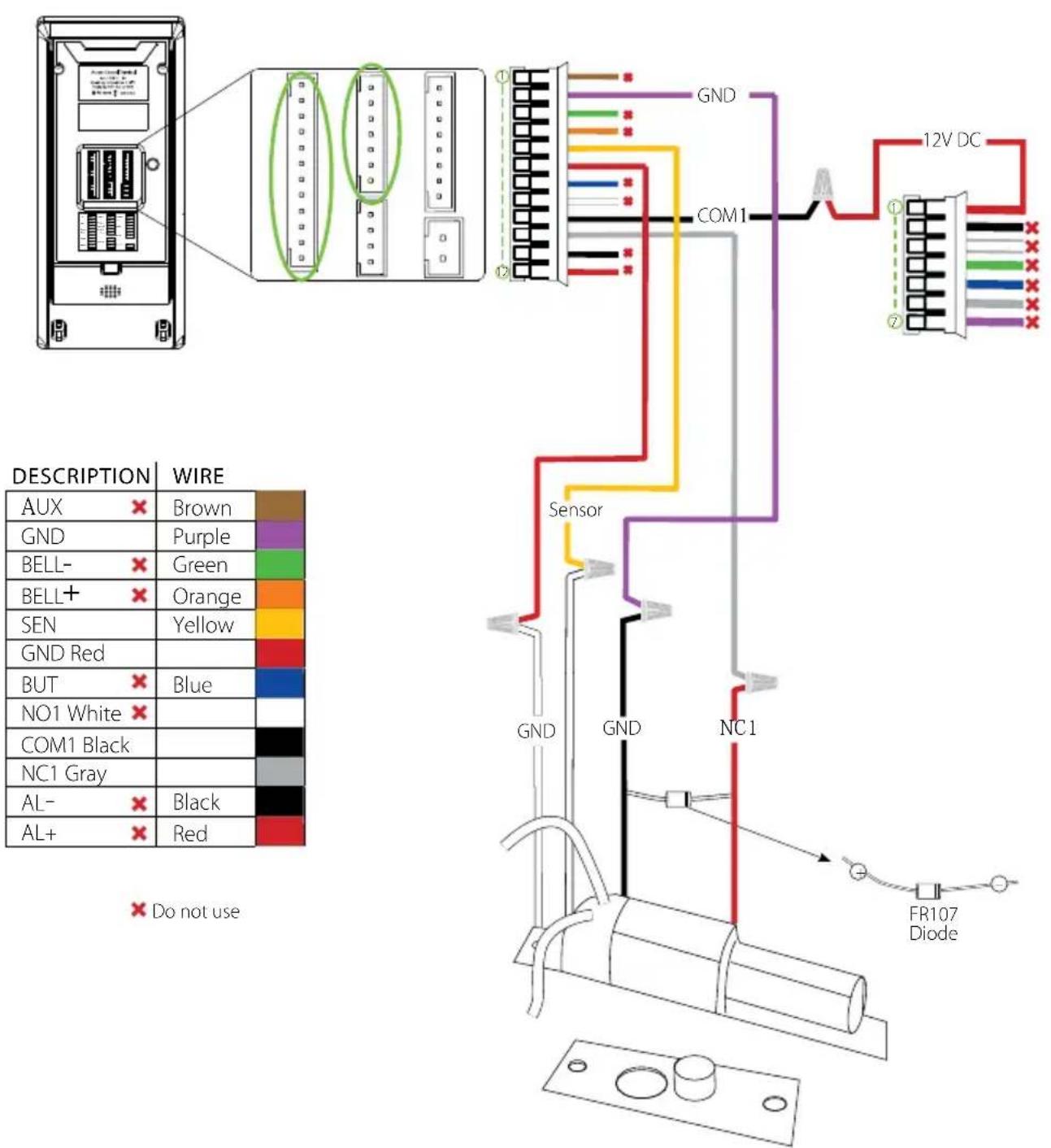
text_image
DESCRIPTION WIRE AUX × Brown GND Purple BELL- × Green BELL+ × Orange SEN Yellow GND Red BUT × Blue NO1 White × COM1 Black NC1 Gray AL- × Black AL+ × Red × Do not use GND GND NC1 12V DC COM1 Sensor FR107 DiodeNormally Closed Lock
Wiegand Output Connection
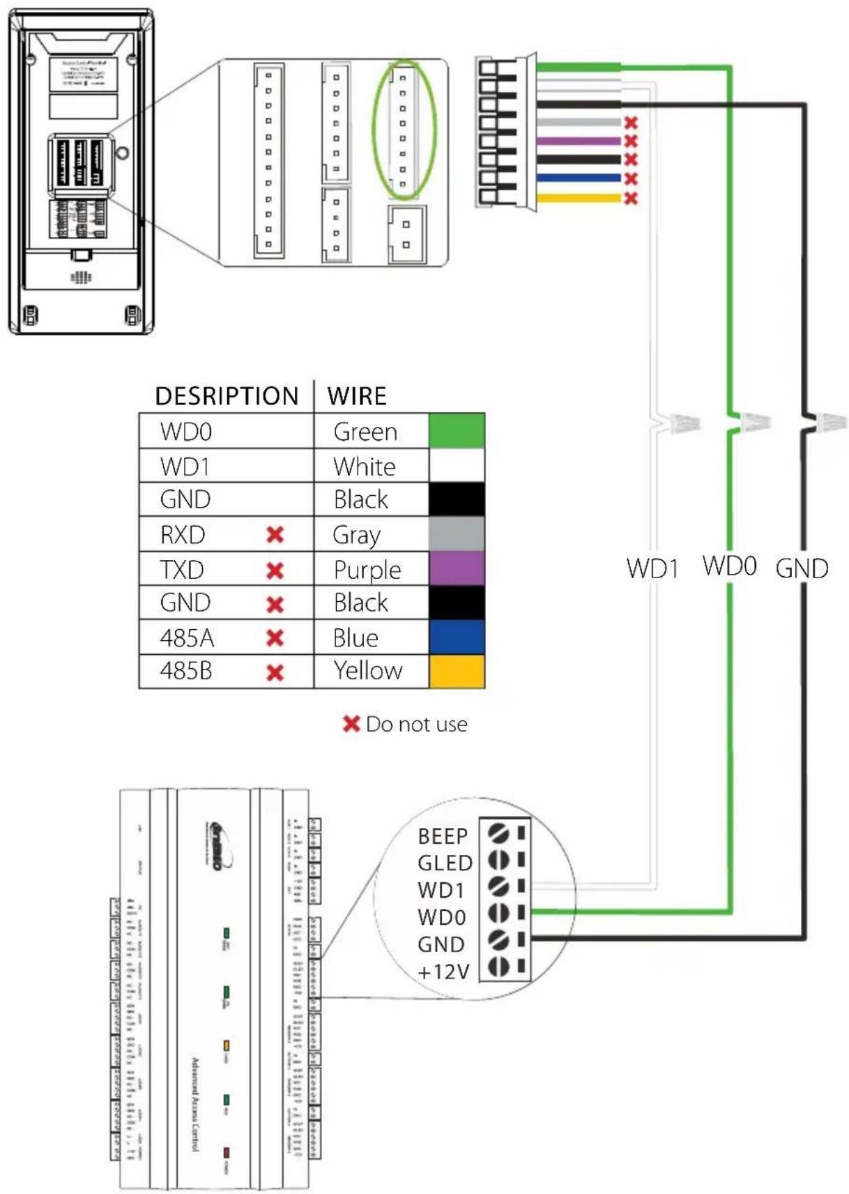
text_image
DESCRIPTION WIRE WD0 Green WD1 White GND Black RXD Gray TXD Purple GND Black 485A Blue 485B Yellow WD1 WD0 GND Do not use BEEP GLED WD1 WD0 GND +12VStandalone Installation
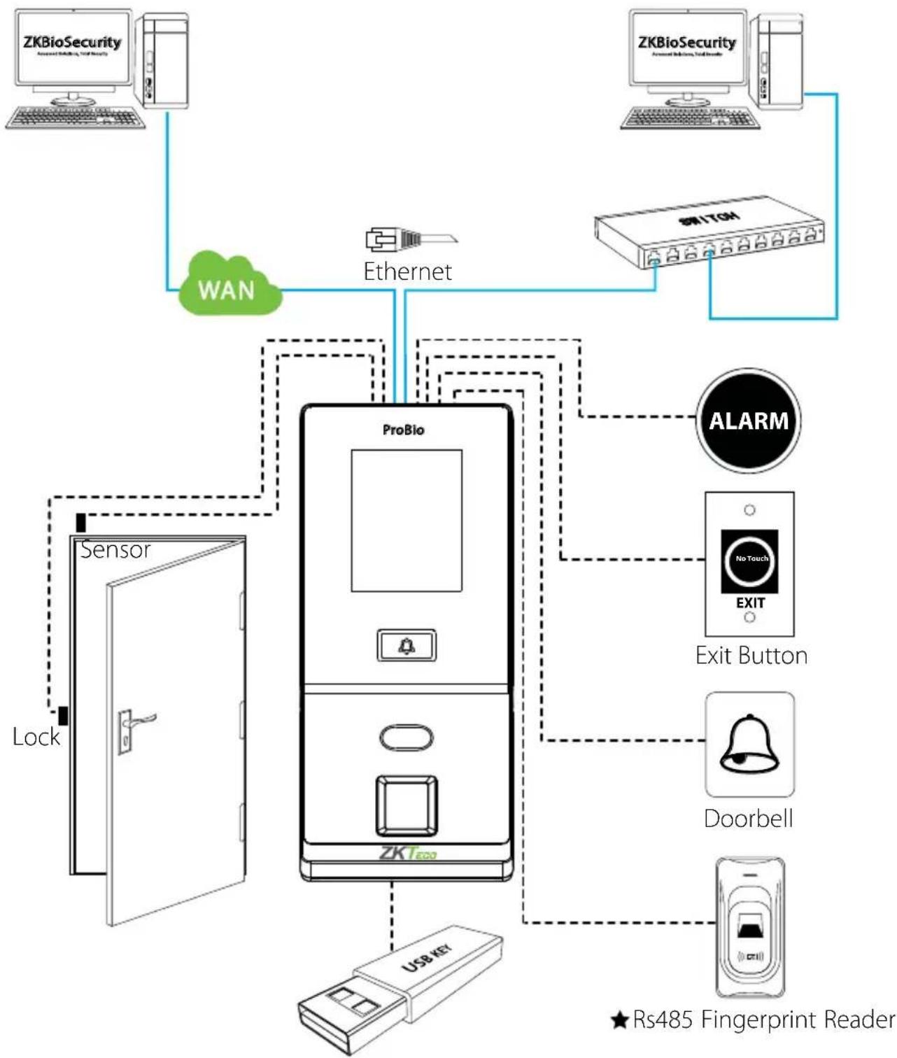
flowchart
graph TD
    A["ZKBioSecurity"] --> B["ProBio"]
    C["ZKBioSecurity"] --> D["Switch"]
    B --> E["USB KEY"]
    D --> F["EXIT Button"]
    E --> G["Sensor"]
    F --> H["Doorbell"]
    G --> I["Lock"]
    H --> J["Ethernet"]
    I --> K["WiN"]
    J --> L["Ethernet"]
    K --> M["RS485 Fingerprint Reader"]
    style A fill:#f9f,stroke:#333
    style C fill:#f9f,stroke:#333
    style D fill:#f9f,stroke:#333
    style E fill:#ccf,stroke:#333
    style F fill:#ccf,stroke:#333
    style G fill:#cfc,stroke:#333
    style H fill:#cfc,stroke:#333
    style I fill:#fcc,stroke:#333
    style J fill:#fcc,stroke:#333
    style K fill:#fcc,stroke:#333
    style L fill:#fcc,stroke:#333
    style M fill:#fff,stroke:#333
    style_N["ALARM"] --> O["Exit Button"]
    N --> P["EXIT"]
    O --> Q["Doorbell"]
    P --> R["RS485 Fingerprint Reader"]
Device Operation
Date/Time Settings
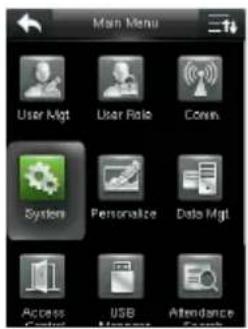
text_image
Main Menu User Mgt User Role Conn Systems Personalize Data Mgt Access USB Attendance Control Manage Search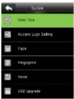
text_image
System Data Time Access Logs Setting Face Fingerprint Reset USB Upgrade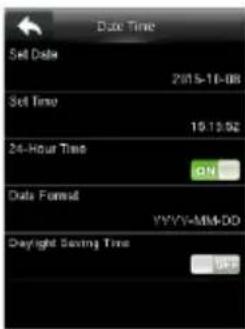
text_image
Date Time Set Date 2015-11-08 Set Time 10:13:02 24-Hour Time ON Data Format YYYY-MM-DD Daylight Saving TimePress 📄 on to enter the Main Menu > System > Date Time to set date and time.
Adding User
text_image
Main Menu User Mgt User Rate Comm System Personalize Data Mgt Access USD Attendance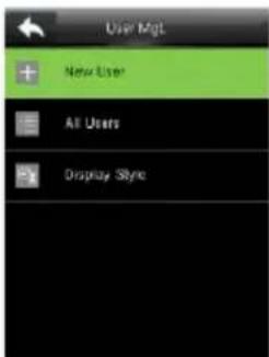
text_image
User Mgt + New User All Users Display Style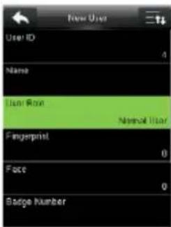
text_image
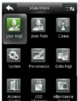
User ID 4 Name User Row Normal User Fingerprint 0 Face 0 Badge NumberPress 📄 icon to enter the Main Menu > User Mgt. > New User to enter the New User adding interface. Settings include entering user ID, user name, choosing user role (Super Admin / Normal User), registering fingerprint / face / badge number ★ / password / user photo, and setting access control role.
Ethernet Settings
text_image
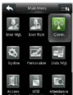
Make Micro User Mgt. User Role Comm. System Personalize Data Mgt. Access Control USD Attendance Camera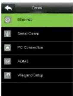
text_image
Comm Ethernet Serial Comm PC Connection ADMS Wiegand Setup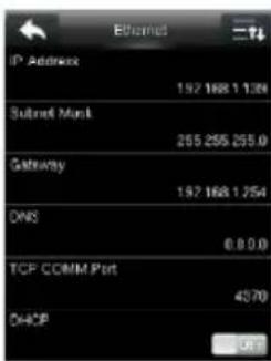
text_image
IP Address 192 168 1 1304 Subnet Mask 255 255 255.0 Gateway 192 168 1 254 DNS 0.0.0.0 TCP COMM Port 4070 DHCPPress 📄n to enter the Main Menu > Comm. > Ethernet.
The parameters below are the system default values. Please adjust them according to the actual network.
IP Address: 192.168.1.201
Subnet Mask: 255.255.255.0
Gateway: 0.0.0.0
DNS: 0.0.0.0
TCP COMM. Port: 4370
DHCP: Dynamic Host Configuration Protocol, which dynamically allocate IP addresses for clients via server. If DHCP is enabled, IP cannot be set manually.
Display in Status Bar: To set whether to display the network icon 📄 on the status bar.
Device Operation
ADMS Settings
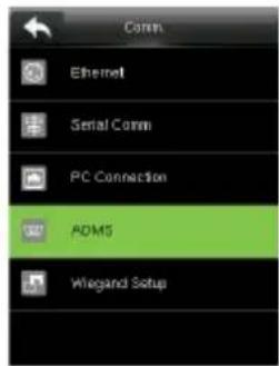
text_image
Comm Ethernet Serial Comm PC Connection ADMS Wiegand Setup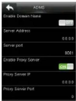
text_image
ADMS Enable Domain Name Server Address 0.0.0.0 Server port B081 Enable Proxy Server ON Proxy Server IP 0.0.0.0 Proxy Server Port 0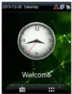
text_image
2015-12-26 Saturday 9 12 3 6 WelcomePress 📄 icon to enter the Main Menu > Comm. > ADMS, to set the parameters which are used for connecting with the ADMS server.
When the Webserver is connected successfully, the initial interface will display the logo.
Enable Domain Name: When this function is turned on, the domain name mode "http://..." will be used, such as http://www.xyz.com.xyz denotes the domain name when this mode is on; when this mode is off, enter the IP address format in xyz.
Server Address: IP address of the ADMS server.
Server Port: Port used by the ADMS server.
Enable Proxy Server: Method of enabling proxy. To enable proxy, please set the IP address and port number of the proxy server. Entering proxy IP and server address will be the same.
Note: To connect the device to ZKBioSecurity software, Ethernet and ADMS options must be set correctly.
Access Control Settings
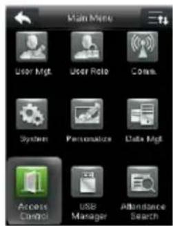
text_image
Main Menu User Mgt User Role Conv System Personalize Data Mgt Access Control USB Manager Attendance Search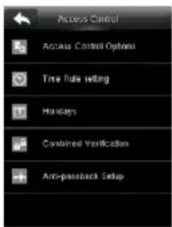
text_image
Access Control Access Control Options Time Rule setting Holidays Combined Verification Anti-passback Setup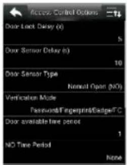
text_image
Access Control Options Door Lock Delay (x) S Door Sensor Delay (y) 10 Door Sensor Type Normal Open (NO) Verification Mode Password/Fingerprint/Dadge/TC Door available time period 1 NO Time Period NonePress 📄n to enter the Main Menu, press Access Control to enter Access Control setting interface. To gain access, the registered user must meet the following conditions:
- User's access time must fall within either user's personal time zone or group time zone.
- User's group must be in the access combo (when there are other groups in the same access combo, verification of members of those groups are also required to unlock the door).
Access Control Options: To set parameters of the lock and other related devices.
Time Rule Setting: To set a maximum of 50 time rules. Each time rule consists of 10 spaces (7 spaces for one week and 3 holiday spaces), each space consists of 3 time periods.
Device Opreation
Holidays: To set dates of holiday and the access control time zone for that holiday.
Combined Verification: To set access control combinations. A combination consists of a maximum of 5 access control groups.
Anti-Passback Setup: To prevent passing back which causes risks to security. Once this function is enabled, entry and exit records must be matched in order to open door. In Anti-Passback, Out Anti-Passback and In/Out Anti-Passback functions are available.
Access Control Combination Settings
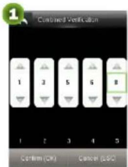
E.g.: Add an access control combination which requires 2 person's verification from both Access Control Group 1 (set in User Management) and Access Control Group 2.
text_image
Combined Verification 1 3 5 6 8 1 2 3 4 5 Confirm (OK) Cancel (ESC)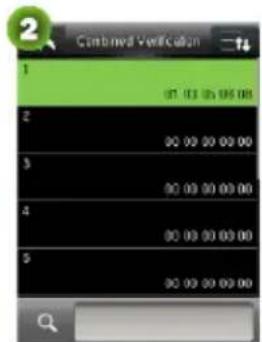
text_image
Combined Verification 1 2 3 4 5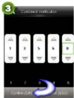
text_image
3 Combined Ventification 1 3 5 6 8 1 2 3 4 5 Confirm (OK) Cancel (ESC)-
In "Combined Verification" list, click the desired combination to modify, and enter the interface (as shown in figure 1).
-
Click "+" or "-" to set the user access control group no., and then click "Confirm" to save and return to "Combined Verification".
Note:
A. A single access control combination can consist of a maximum of 5 access control groups (in order to open door, verification of all 5 users is required).
B. If the combination is set as shown in figure 3, a user from access control group 2 must obtain verification of 2 users from access control group 1 in order to open door.
C. Set all access control group number to zero to reset access control combination.
Troubleshooting
Q: "Invalid Time Period" is displayed after verification?
A : Contact Administrator to check if the user has the privilege to gain access within that time zone.
Q: Verification succeeds but the user cannot gain access?
A: Check whether the lock wiring is correct.
Q: The Tamper Alarm rings?
A : To cancel the triggered alarm mode, carefully check whether the device and back plate are securely connected to each other, and reinstall the device properly if necessary.
Q: How to cancel alarms?
A: Verify a registered user.
ZKBioSecurity 3.0
It is recommended to install software version 3.0.3.0 or above

text_image
ZKTeco ZKBioSecurity 3.0 ✓ Easy to configure and use ✓ Door management ✓ Linkage settings ✓ Real-time monitoring ✓ Maps reports and maintenance ✓ Stop availability to this party integrationInstallation & Setup
Downloading....17
Installation....18
Adding Device....20
Creating a Time Zone....22
Creating an Access Level 23
Enrolling Personnel 24
Wiegand Format....26
Add & Delete Personnel to Access Level......27
Real-Time Monitoring 28
Exporting Reports....29
Downloading
- Go to http://www.zkteco.com/product/ZKBioSecurity3.0_421.html
- Download the latest software and related files as required.

text_image
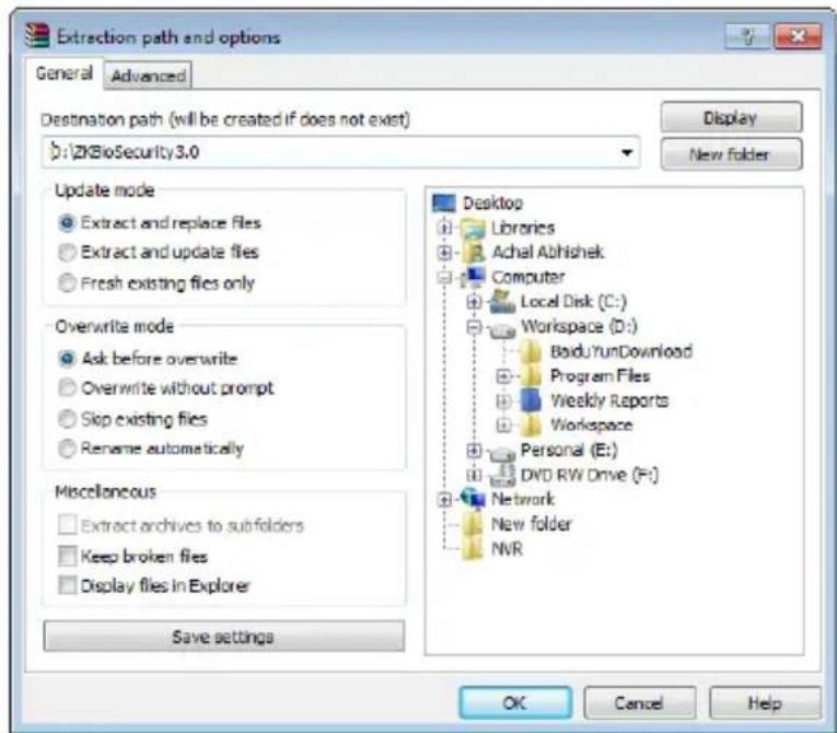
ZKTecO PRODUCTS SOLUTIONS SUPPORT NEWS COMPANY SUPPLIER PLATFORM 中国 Verification Center My ZKTeco Time Attendance Overview Function Specification Download Change Log Access Control + Standalone Device + Control Panel + Reader + Accessory - Software & APP • APP Enterprise Security Platform → ZKBioSecurity3.0 • SMB AC Software Entrance Control Green Label Surveillance ZKBioSecurity3.0 1.52MB Data Sheet 2017-03-29 Overseas_ZKBioSecurity3.0.3.0_R Installation File 507.0MB Software 2017-03-10 ES_ZKBioSecurity3.0.1.1_R installation file 508.0MB Software 2016-09-30- Once downloaded, extract the rar file to a new folder.
- Click on setup to begin installation.

MainResource

Pubs

UpdatePack

setup
text_image
Extraction path and options General Advanced Destination path (will be created if does not exist) D:\ZKBioSecurity3.0 Update mode Extract and replace files Extract and update files Fresh existing files only Overwrite mode Ask before overwrite Overwrite without prompt Skip existing files Rename automatically Miscellaneous Extract archives to subfolders Keep broken files Display files in Explorer Save settings Desktop Libraries Achal Abhilshek Computer Local Disk (C:) Workspace (D:) BaiduYunDownload Program Files Weekly Reports Workspace Personal (E:) DVD RW Drive (F:) Network New folder NVR OK Cancel HelpInstallation
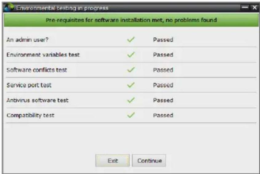
- System will check the requirements to install the software. Click Continueifall tests are passed, else check the issues and re-test.
text_image
Environmental testing in progress Pre-requisites for software installation met, no problems found An admin user? ✓ Passed Environment variables test ✓ Passed Software conflicts test ✓ Passed Service port test ✓ Passed Antivirus software test ✓ Passed Compatibility test ✓ Passed Exit Continue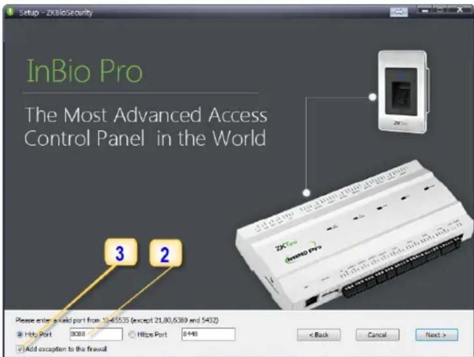
text_image
Setup - ZKBioSecurity InBio Pro The Most Advanced Access Control Panel in the World 3 2 ZKBio Pro InBio Pro Please enter a valid port from 1046535 (except 21,80,6380 and 5432) @ Http Port 8088 ○ Https Port 8448 < Back Cancel Next > ✓ Add exception to the firewall- Add an open port (Default 8088) or ask a network administrator for an open port. Note: Stanalone device doesn't support https.
- Click the check box to add firewall exception for this port.
Installation
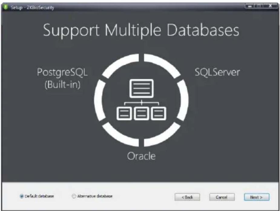
- Select the mode of database. The default will be PostgreSQL, if you want to select any other database, then select Alternative database.
text_image
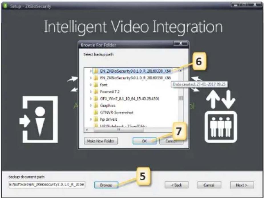
Setup - ZKBioSecurity Support Multiple Databases PostgreSQL (Built-in) SQLServer Oracle Default database Alternative database < Back Cancel Next >- Click Browse and choose or create a folder to store your backup files.
- Select/Create the required folder.
- Click OK.
text_image
Setup - ZKBioSecurity Intelligent Video Integration Browse For Folder Select backup path EN_ZKBioSecurity3.0.1.0_R_20160330_X64 EN_ZKBioSecurity3.0.1.0_R_20160330_X85 font Frammail 7.2 GFX_Win7_8.1_10_64_15.40.28.4501 Graphics GTNVR-Screeshot hp drivers HP Notebook_15.xsd016x OK Cancel Make New Folder Date created: 27-01-2017 09:25 6 7 5 backup document path ENSoftwareEN_ZKBioSecurity3.0.1.0_R_2016K Browse < Back Cancel Next >Adding Device
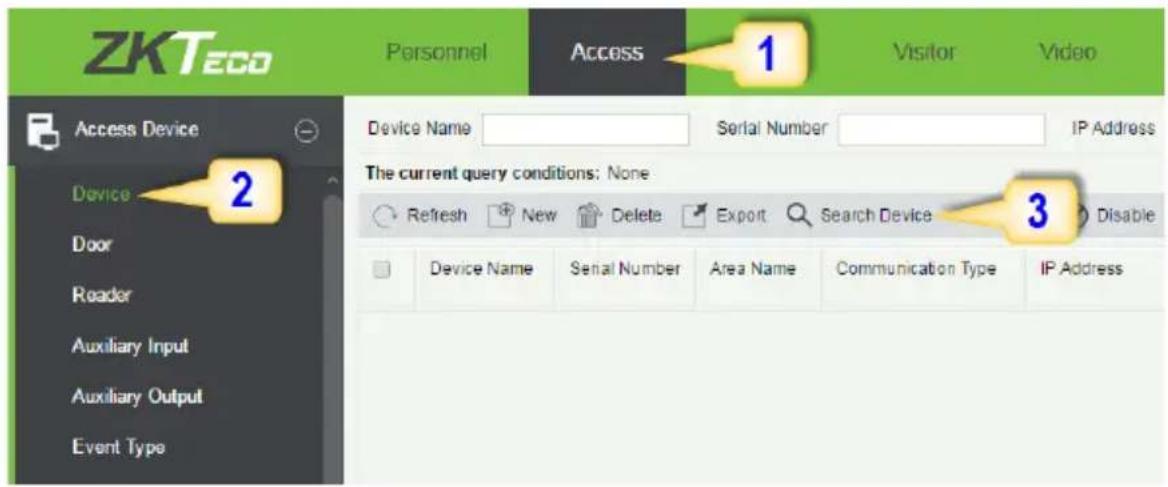
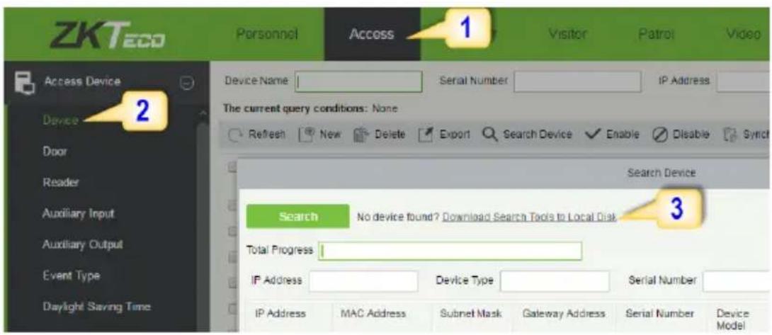
- Click on Access to get below interface of Access Module of the software.
text_image
ZKTeco Personnel Access 1 Visitor Video Access Device Device 2 Door Reader Auxiliary Input Auxiliary Output Event Type Device Name Serial Number IP Address The current query conditions: None Refresh New Delete Export Search Device Disable Device Name Serial Number Area Name Communication Type IP Address- Click on Device.
- Click on Search Device.
text_image
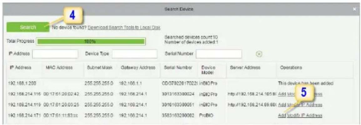
Search Device Search No device found? Download Search Tools to Local Disk Total Progress 100% IP Address Device Type Serial Number IP Address MAC Address Subnet Mask Gateway Address Serial Number Device Model Server Address Operations 192.168.1.200 255.255.255.0 192.168.1.1 ODG70220170221 InBIO Pro This device has been added 192.168.214.116 00:17:51:20:02:42 255.255.255.0 192.168.214.1 3013163300024 InBIO Pro http://192.168.214.105.80 Add Modify IP Address 192.168.214.119 00:17:61:20:03:25 255.255.255.0 192.168.214.1 3010163300051 InBIO Pro http://192.168.214.09:80 Add Modify IP Address 192.168.214.171 00:17:61:11:83:00 255.255.255.0 192.168.214.1 3583163200002 ProBIO Add Modify IP Address- Click Search to search all the sandalone devices on the network.
- From the list, click Add to add the required device.
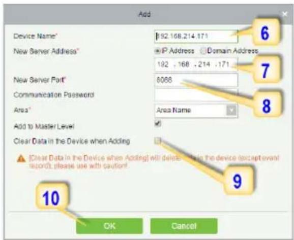
text_image
Add Device Name* 192.168.214.171 New Server Address* IP Address Domain Address 192 . 168 . 214 . 171 New Server Port* 6066 Communication Password Area* Area Name Add to Master Level Clear Data in the Device when Adding Clear Data in the Device when Adding will delete a file in the device (except event record), please use with caution? OK CancelAdding Device
- Enter a unique name.
- Enter the IP address of current system (PC).
- Enter the access point of system.
- Click on this option, after adding device, the system will clear all data in the device (except the event logs).
- Click OK to finish.
The default IP address may conflict with the device IP of other devices. In order to avoid that problem, modify the IP address as shown below:
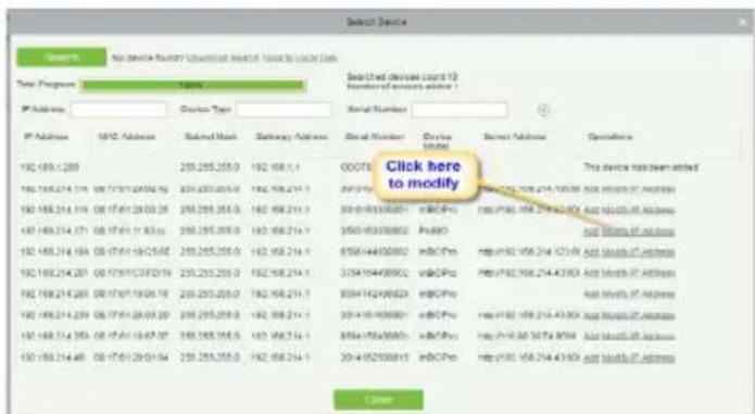
text_image
Search Device Search No. (M) (M) (M) (M) (M) (M) (M) (M) Time Progress 10:00:00 Search Type Serial Number IP Address MID Address Submodel Mask Pathway Address Serial Number Device Index Server Address Operator 192.169.1.209 255.265.255.0 192.168.1.1 00078 Click here to modify This device has been added. 192.169.214.176 192.171/21.00/2.92 255.265.255.0 192.168.214.1 350.0/8/30/00/00 eBOPPro http://8/8/168.214.43.90X And Tools.PA Address http://8/8/168.214.43.90X And Tools.PA Address http://8/8/168.214.43.90X And Tools.PA Address http://8/8/168.214.43.90X And Tools.PA Address http://8/8/168.214.43.90X and Tools.PA Address http://8/8/168.214.43.90X and Tools.PA Address http://8/8/168.214.43.90X and Tools.PA Address http://8/8/168.214.43.90X and Tools.PA Address http://8/8/168.214.43 00/00/00/00 http://8/8/168.214.43.90X and Tools.PA Address http://8/8/168.214.43.90X and Tools.PA Address http://8/8/168.214.43.90X and Tools.PA Address http://8/8/168.214.43 00/16/16-29/01-04 255.265.255.0 192.168.214.1 350.0/8/30/00/00 eBOPPro http://8/8/168.214.43.90X And Tools.PA Address http://8/8/168.214.43.90X and Tools.PA Address http://8/8/168.214.43 00/16/16-29/01-04 350.0/8/30/00/00 eBOPPro http://8/8/168.214.43.90X And Tools.PA Address http://8/8/168.214.43 00/16/16-29/01-04 350.0/8/30/00/00 eBOPPro http://8/8/168.214.43 00/16/16-29/01-04 http://8/8/168.214.43 00/16/16-29/01-04 http://8/8/168.214 00/16/16-29 00/16/16-29 00/16/16-29 00/16/16-29 00/16/16-29 00/16/16-29 00/16/16-29 00/16/16-29 00/16/16-29 00 / 255 255 255 255 255 255 255 255 255 255 255 255 255 255 255 255 255 255 255 255 255 255 255 255 255 25 CancelWhen the device is not in the same network with server, customers should download the tool and search the device as shown below:
text_image
ZKTec Personnel Access 1 Visitor Patrol Video Access Device Device Door Reader Auxiliary Input Auxiliary Output Event Type Daylight Saving Time Device Name Serial Number IP Address The current query conditions: None Refresh New Delete Export Search Device Enable Disable Synch Search Device Search No device found? Download Search Tools to Local Disk Total Progress IP Address Device Type Serial Number IP Address MAC Address Subnet Mask Gateway Address Serial Number Device Model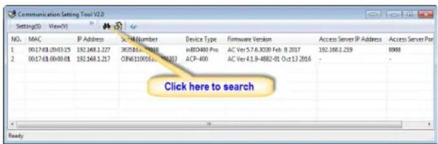
text_image
Communication Setting Tool V2.0 Setting(S) View(V) NO. MAC IP Address X#1 Number Device Type Firmware Version Access Server IP Address Access Server Port 1 00:17:61.20:03.15 192.168.1.227 363516.4.2016 InEIO400 Pro AC Ver 3.7.6.3030 Feb B 2017 192.168.1.219 8088 2 00:17:61.00:00.01 192.168.1.217 OIN6110016.2.2016 ACP-400 AC Ver 4.1.9-4882-01 Oct 13 2016 - Click here to search ReadyCreating a Time Zone
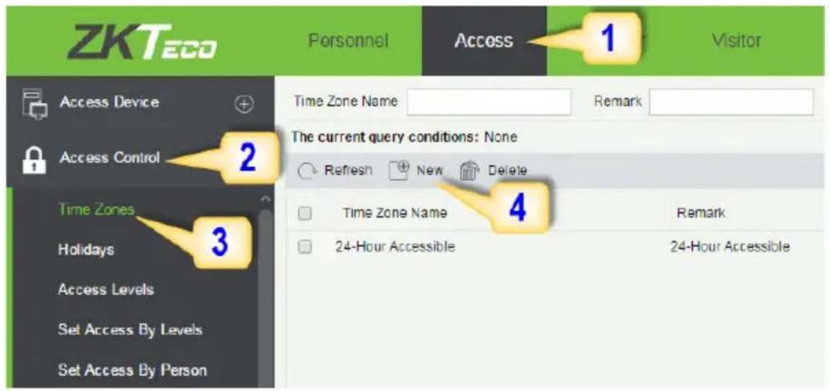
Click Access Control > Time Zones > Add to access the time zone setting interface.
text_image
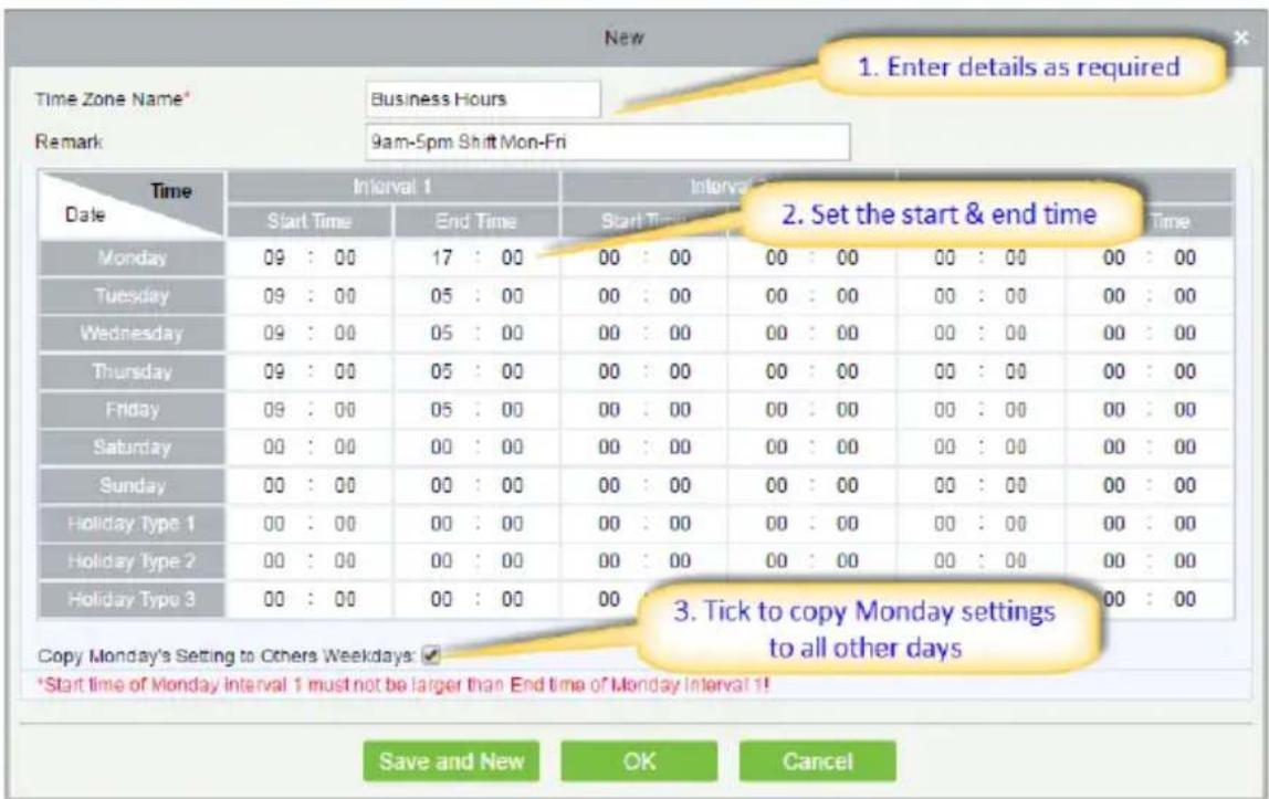
ZKTeco Personnel Access 1 Visitor Access Device + Access Control 2 Time Zones Holidays Access Levels Set Access By Levels Set Access By Person The current query conditions: None Refresh New Delete 4 Remark 24-Hour Accessible 24-Hour AccessibleAfter setting the time zone, click OK to save, and the time zone will appear in the list.
text_image
New Time Zone Name Business Hours Remark 9am-5pm Shift Mon-Fri 1. Enter details as required Time Date Time Date Start Time End Time Start Time End Time Monday 09 : 00 17 : 00 00 : 00 00 : 00 00 : 00 00 : 00 00 : 00 Tuesday 09 : 00 05 : 00 00 : 00 00 : 00 00 : 00 Wednesday 09 : 00 05 : 00 00 : 00 00 : 00 00 : 00 00 : 00 Thursday 09 : 00 05 : 00 00 : 00 00 : 00 00 : 00 00 : 00 Friday 09 : 00 05 : 00 00 : 00 00 : 00 00 : 00 00 : 00 Saturday 00 : 00 00 : 00 00 : 00 00 : 00 00 : 00 00 : 00 Holiday Type 1 00 : 00 00 : 00 00 : 00 Holiday Type 2 00 : 00 00 : 00 Holiday Type 3 00 : 00 Holiday Type 4 3. Tick to copy Monday settings to all other days Copy Monday's Setting to Others Weekdays: ✓ *Start time of Monday interval 1 must not be larger than End time of Monday interval 1! Save and New OK CancelCreating an Access Level
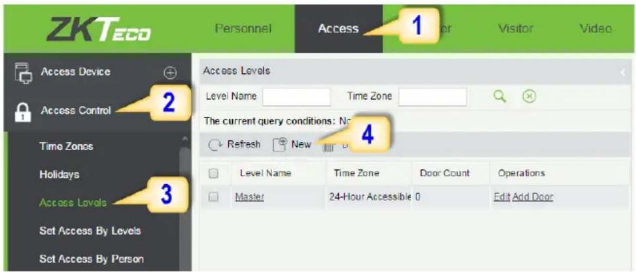
- Click Access 2. Click Access Control 3. Click Access Levels 4. Click New.
text_image
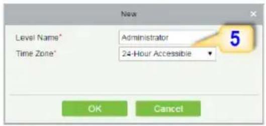
ZKTecO Personnel Access 1 Visitor Video Access Device + 2 Access Control Time Zones Holidays Access Levels Set Access By Levels Set Access By Person Access Levels Level Name Time Zone The current query conditions: No 4 Refresh New Level Name Time Zone Door Count Operations Master 24-Hour Accessible 0 Edit Add Door- Enter the details and click OK.
text_image
Level Name* Time Zone* New Administrator 24-Hour Accessible OK Cancel- You need to add doors to the access levels.
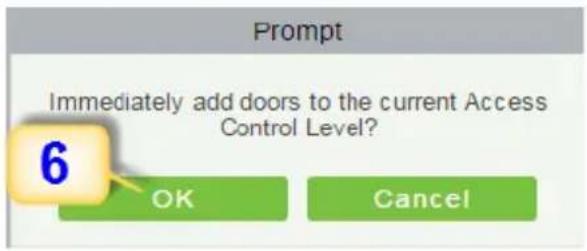
text_image
Prompt Immediately add doors to the current Access Control Level? 6 OK Cancel- Select the required door(s).
- Move the selected door(s).
- Click OK to finish adding doors.
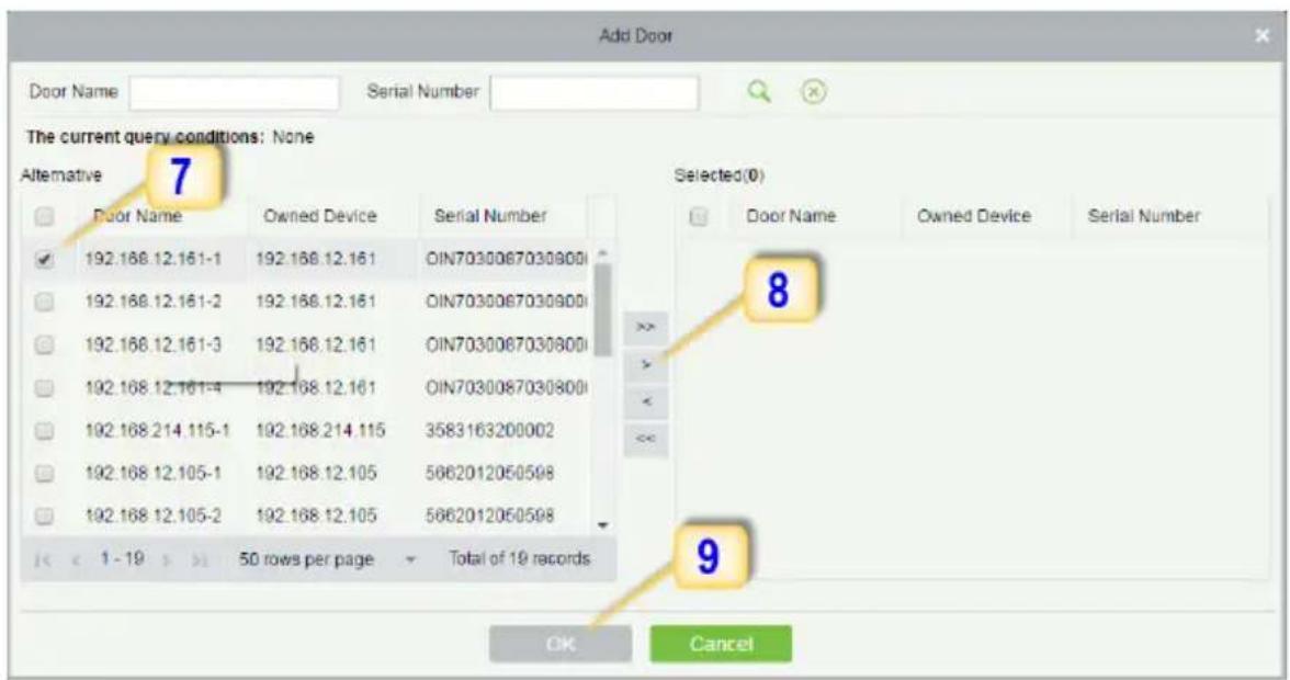
text_image
Add Door Door Name Serial Number The current query conditions: None Alternative 7 Selected(0) Door Name Owned Device Serial Number 192.168.12.161-1 192.168.12.161 OIN7030067030900 192.168.12.161-2 192.168.12.161 OIN7030067030900 192.168.12.161-3 192.168.12.161 OIN7030067030900 192.168.12.161-4 192.168.12.161 OIN7030067030900 192.168.214.115-1 192.168.214.115 3583163200002 192.168.12.105-1 192.168.12.105 5662012050598 192.168.12.105-2 192.168.12.105 5662012050598 << 1 - 19 >> 50 rows per page Total of 19 records OK CancelEnrolling Personnel
- Click Personnel 2. Click Person 3. Click New to add personnel.
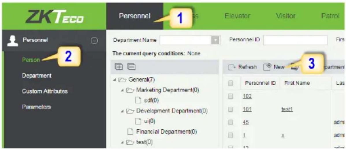
text_image
ZKTecO Personnel 1 Elevator Visitor Patrol Personnel Name Personnel ID First 2 Department The current query conditions: None General(7) Marketing Department(0) sdf(0) Development Department(0) ui(0) Financial Department(0) test(0) Refresh New 3 Personnel ID First Name Las 102 101 test1 45 1 x admin admin admin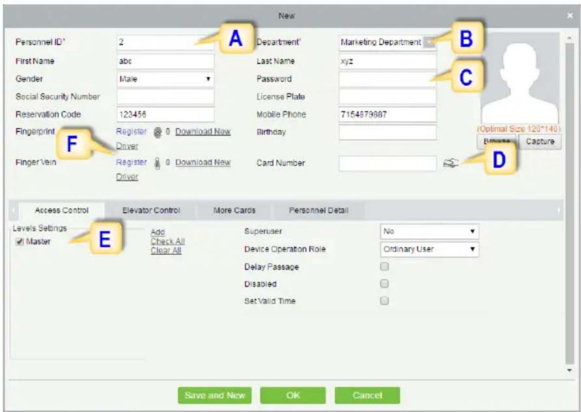
text_image
New Personnel ID* 2 First Name abc Gender Male Social Security Number Reservation Code 123456 Fingerprint Register Download New Driver Finger Vein Register Download New Driver Department* Last Name Password License Plate Mobile Phone 7154879687 Birthday Card Number Access Control Elevator Control More Cards Personnel Detail Levels Settings Add Device Operation Role No ✓ Master Check All Ordinary User Clear All Delay Passage Disabled Set Valid Time Save and New OK Cancel B C (Optimal Size 120*140) Browse Capture DA. Personnel ID: It must be a unique 9 characters length with the valid range of 1-79999999. It can be configured based on actual conditions. The Personnel No. contains only numbers by default but may also include letters after setting parameters.
Enrolling Personnel
B. Department: Select from the pull-down menu and click OK. If the department was not set previously, you can only select the default [Company Name] department.
C. Password: Set personnel password. It only supports 6-digit passwords. If password exceeds the specified length, the system will truncate it automatically. It can't be same with duress or other passwords.
D. Card Number: You can add a card number through manual entry or a card issuer. For issuing through issuer, click on the card icon directly. For issuing card manually, you must enter both the card number and the site code, then the software converts the numbers to the card number for access control system verification.
E. Access Control: Here you will get all the access levels created by you and by default. Tick the required box.
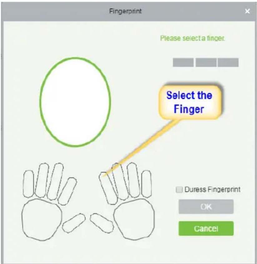
F. Fingerprint: Enroll the Personnel Fingerprint or Duress Fingerprint. Duress Fingerprint is to trigger the alarm and send the signal to the system in case of emergency.
text_image
Fingerprint Please select a finger. Select the Finger Duress Fingerprint OK CancelWiegand Format
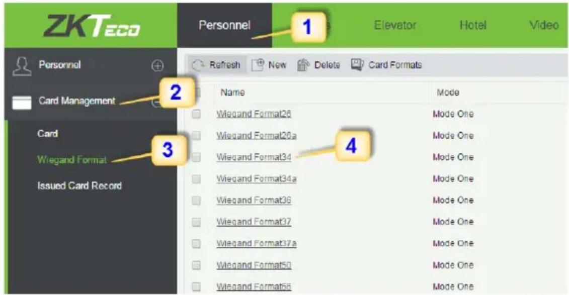
Wiegand Format is the card format that can be identified by Wiegand reader. The software is embedded with 10 Wiegand formats. You may set the Wiegand card format as required.
- Click Personnel 2. Click Card Management 3. Click Wiegand Format.
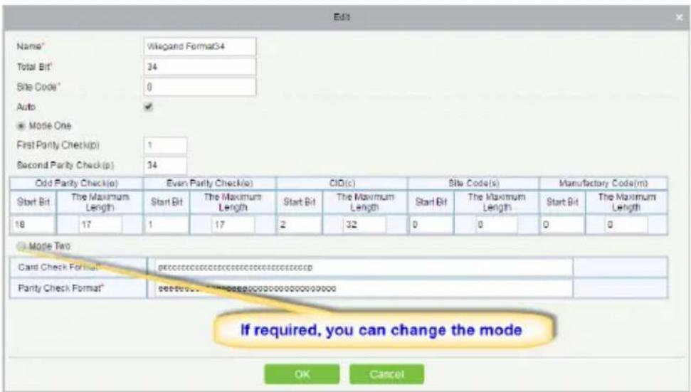
- Taking Wiegnad Format34 as an example. Click to edit.
text_image
ZKTeco Personnel Card Management Card Wiegand Format Issued Card Record 1 Elevator Hotel Video Refresh New Delete Card Formats Name Wiegand Format26 Wiegand Format26a Wiegand Format34 Wiegand Format34a Wiegand Format36 Wiegand Format37 Wiegand Format37a Wiegand Format50 Wiegand Format56 Mode Mode One Mode One Mode One Mode One Mode One Mode One Mode OneThis software supports two modes for adding Wiegand Format, if mode 1 does not meet your setting requirement, switch to mode 2.
text_image
Name* Wiegand Format34 Total Bit* 34 Site Code* 0 Auto Mode One First Parity Check(p) 1 Second Parity Check(p) 34 Odd Parity Check(o) Even Parity Check(s) CID(c) Site Code(s) Manufactory Code(m) Start Bit The Maximum Length Start Bit The Maximum Length Start Bit The Maximum Length Start Bit The Maximum Length 18 17 1 17 2 32 0 0 0 0 Mode Two Card Check Format* pccccccccccccccccccccccccccccp Parity Check Format* seecceccctcctgacggcccccccccccccccccccccccp If required, you can change the mode OK Cancelp indicates Parity Position, s indicates Site Code, c indicates Cardholder ID, f indicates Facility Code, m indicates Manufactory Code, e indicates Even Parity, O indicates Odd Parity, b indicates both odd check and even check, x indicates parity bits no check.
Add & Delete Personnel to Access Level
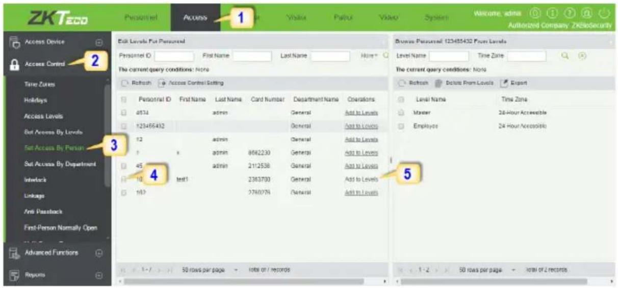
- Click Access 2. Access Control 3. Set Access by Person 4. Click on the required employee 5. Click Add to Levels.
text_image
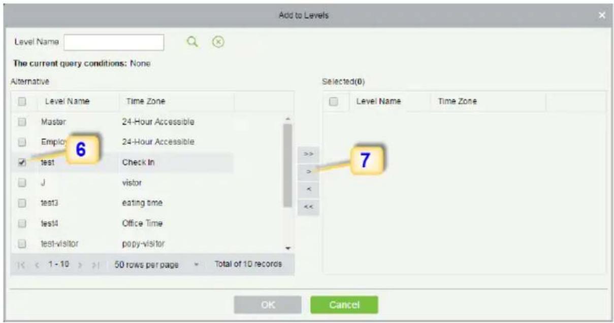
ZKTecO Personalnel Access 1 Value Pathur Video System Welcome: admin Authorized Company: ZKBioSecurity Access Device Access Control Time Zones Holidays Access Levels Set Access By Levels Set Access By Person Set Access By Department Interlock Linkages Anti Pastrack First-Person Normally Open Advanced Functions Reports Edit Levels For Personnel Personnel ID First Name Last Name None The current query conditions: None Refresh Access Control Setting Personnel ID First Name Last Name Card Number Department Name Operations 4534 admin General Add to Levels 125465432 General Add to Levels 12 admin General Add to Levels x admin 8562230 General Add to Levels 45 admin 2112538 General Add to Levels 10 test1 2383790 General Add to Levels 107 2780776 General Add to Levels Browse Personnel: 123485432 Four Levels Level Name Time Zone The current query conditions: None Refresh Delete From Levels Export Level Name Time Zone Master 24-Hour Accessible Employee 24 Hour Accessible 1-2 50 rows per page total or / records 1-2 50 rows per page total of 2 records- Select Level(s).
- Click to move the selected level(s) to the right, and then click OK to complete adding. The added level(s) will appear in the list on to the right side.
text_image
Add to Levels Level Name: The current query conditions: None Alternative Selected(0) Level Name Time Zone Master 24-Hour Accessible Employ 24-Hour Accessible test Check In J vistor test3 eating time test4 Office Time test-visitor popy-visitor 1 - 10 > 50 rows per page Total of 10 records OK CancelReal -Time Monitoring
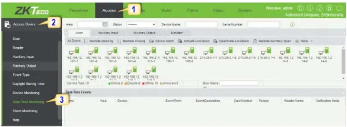
1. Click Access 2. Click Access Device 3. Click Real-Time Monitoring
Real-time monitor the status and real-time events of standalone in the system, including normal events and abnormal events (including alarm events) device transactions.
text_image
ZKTecO Personnel Access 1 Device Name Serial Number Area Status Device Name Serial Number Door Auxiliary Input Auxiliary Output Indicator All Options Remote Opening Remote Closing Cancel Alarm Activate Lockdown Deactivate Lockdown Remote Normally Open More 162.108.12 192.108.12 192.108.12 192.108.214 192.108.12 192.108.12 210.28.0.1-1 210.28.0.1-2 210.28.0.1-3 210.28.0.1-4 192.108.1.2 192.108.1.2 192.108.1.2 105-1 105-2 105-3 105-4 105-5 105-6 105-7 105-8 105-9 105-10 105-11 105-12 105-13 105-14 105-15 105-16 105-17 105-18 105-19 105-20 105-21 105-22 105-23 105-24 105-25 105-26 105-27 105-28 105-29 105-30 Current Total: 19 Online: 0 Disable: 0 Office: 19 Unknown: 0 Door Name: Real-Time Events Name Area Device EventPoint EventDescription Card Number Person Reader Name Verification Mode Access Device Door Reader Auxiliary Input Auxiliary Output Event Type Light Saving Time Device Monitoring Real-Time Monitoring Alarm Monitoring MapYou can also filter by Area, device name, Serial number to check a specific device transactions or all at once.
Hover over a door icon to open pop up menu as shown below and click Remote Closing, Remote Opening, or Cancel Alarm and more.
| Status | |
| Device: | 192.168.1.217 |
| Serial Number: | OIN6110016102200203 |
| Number: | 1 |
| Door Sensor: | No Door Sensor |
| Relay: | Close |
| Alarm: | None |
| Remote Opening | |
| Remote Closing | |
| Cancel Alarm | |
| Remote Normally Open | |
| Enable Intraday Passage Mode Time Zone | |
| Disable Intraday Passage Mode Time Zone | |
| Query the latest events from the door | |
Exporting Reports
Access Module:
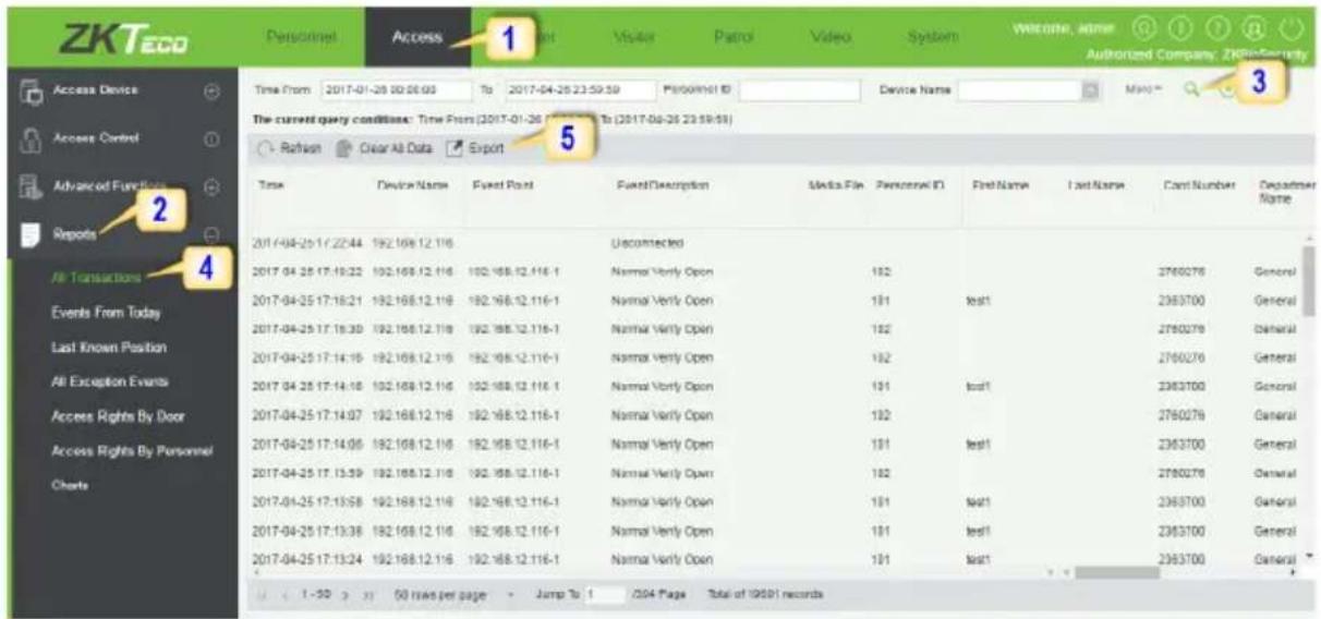
- Click Access 2. Click Reports 3. Filter the data (time, Personnel ID, Device Name and more) if required and click on search 4. Click All transactions or as required.
text_image
ZKTecO Access Device Access Control Advanced Functions Reports All Transactions Events From Today Last Known Position All Exception Events Access Rights By Door Access Rights By Personnel Charts Time From 2017-01-26 00:00 To 2017-04-25 23:59:59 Refuse Clear All Data Export Time Device Name Event Port Found/Description Media File Personnel ID First Name Last Name Card Number Department Name 2017-04-25 17:22:44 192.168.12.116 Unconnected 2017-04-25 17:19:22 192.168.12.116 Normal Vrly Open 192 2017-04-25 17:18:21 192.168.12.116 Normal Vrly Open 191 test1 2017-04-25 17:18:30 192.168.12.116 Normal Vrly Open 192 2017-04-25 17:14:15 192.168.12.116 Normal Vrly Open 192 2017-04-25 17:14:16 192.168.12.116 Normal Vrly Open 191 test1 2017-04-25 17:14:07 192.168.12.116 Normal Vrly Open 192 2017-04-25 17:14:06 192.168.12.116 Normal Vrly Open 191 test1 2017-04-25 17:13:59 192.168.12.116 Normal Vrly Open 192 2017-04-25 17:13:58 192.168.12.116 Normal Vrly Open 191 test1 2017-04-25 17:13:38 192.168.12.116 Normal Vrly Open 191 test1 2017-04-25 17:13:24 192.168.12.116 Normal Vrly Open 191 test1 3 The current query conditions: Time From (2017-04-25 23:59:59) Refuse Clear All Data Export Unconnected Normal Vrly Open 192 Normal Vrly Open 191 test1 Normal Vrly Open 192 Normal Vrly Open 192 Normal Vrly Open 191 test1 Normal Vrly Open 192 Normal Vrly Open 192 Normal Vrly Open 192 Normal Vrly Open 192 Normal Vrly Open 192 Normal Vrly Open 192 Normal Vrly Open 192 Normal Vrly Open 192 Normal Vrly Open 192 Normal Vrly Open 192 Normal Vrly Open 193 Normal Vrly Open 193 Normal Vrly Open 193 Normal Vrly Open 193 Normal Vrly Open 193 Normal Vrly Open 193 Normal Vrly Open 193 Normal Vrly Open 193 Normal Vrly Open 193 Normal Vrly Open 193 Normal Vrly Open 194 Normal Vrly Open 194 Normal Vrly Open 194 Normal Vrly Open 194 Normal Vrly Open 194 Normal Vrly Open 194 Normal Vrly Open 194 Normal Vrly Open 194 Normal Vrly Open 194 Normal Vrly Open 194 Normal Vrly Open 195 Normal Vrly Open 195 Normal Vrly Open 195 Normal Vrly Open 195 Normal Vrly Open 195 Normal Vrly Open 195 Normal Vrly Open 195 Normal Vrly Open 195 Normal Vrly Open 195 Normal Vrly Open 195 Normal Vrly Open 196 Normal Vrly Open 196 Normal Vrly Open 196 Normal Vrly Open 196 Normal Vrly Open 196 Normal Vrly Open 196 Normal Vrly Open 196 Normal Vrly Open 196 Normal Vrly Open 196 Normal Vrly Open 196 Normal Vrly Open 197 Normal Vrly Open 197 Normal Vrly Open 197 Normal Vrly Open 197 Normal Vrly Open 197 Normal Vrly Open 197 Normal Vrly Open 197 Normal Vrly Open 197 Normal Vrly Open 197 Normal Vrly Open 198 Normal Vrly Open 198 Normal Vrly Open 198 Normal Vrly Open 198 Normal Vrly Open 198 Normal Vrly Open 198 Normal Vrly Open 198 Normal Vrly Open 198 Normal Vrly Open 198 Normal Vrly Open 198 Normal Vrly Open 19-
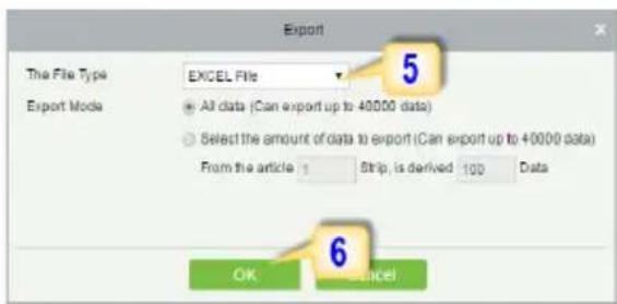
Click on Export to get the list.
-
Click OK.
text_image
Export The File Type EXCEL File Export Mode All data (Can export up to 40000 data) Select the amount of data to export (Can export up to 40000 data) From the article 1 Strip, is derived 100 Data OK CancelPersonnel Module:
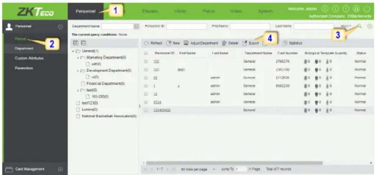
- Click Personnel 2. Click Person 3. Filter the data (Department, Personnel ID, and more) if required and click on search 4. Click on Export to get the list.
text_image
ZKTeco Personnel 1 Elevator Visitor Patrol Video System Welcome: admin Authorized Company: ZKBioSecurity Department Name Personnel ID FirstName LastName More The current query conditions: None 4 Statistics Retest New AdjustDepartment Delete Export Personnel ID First Name I set Name Department Name Cast Number Biological Template Quantity Status 102 General 2768276 0 0 0 Normal 101 3001 General 2951/00 0 0 0 0 Normal 45 admin General 2112638 0 0 0 0 Normal 1 x admin General 5692230 0 0 0 0 Normal 12 admin General 0 0 0 0 Normal 1524 admin General 0 0 0 0 Normal 123455432 General 0 0 0 0 Normal Card Management 50 rows per page Jump To 1 In Page Total of 7 records6 Kingsbridge Road, Suite 8
Fairfield, NJ 07004
T:+1 862 505 2101
sales@zkaccess.com
www.zkaccess.com