
Z8564 - Security Camera ZKTeco - Free user manual and instructions
Find the device manual for free Z8564 ZKTeco in PDF.


| Product Type | Network Video Recorder (NVR) |
| Brand | ZKTeco |
| Model | Z8564 |
| Dimensions | 350 x 300 x 60 mm (approx.) |
| Weight | 5 kg (approx.) |
| Power Supply | AC 100-240V, 50/60Hz, 1.5A |
| Power Consumption | ≤ 30W (without HDD) |
| Video Input | Up to 16 IP cameras |
| Video Compression | H.264 / H.265 |
| Recording Resolution | Up to 8MP (4K) |
| Hard Disk Interface | SATA, up to 4 HDDs (each up to 10TB) |
| Display Output | 1 x HDMI, 1 x VGA |
| Network Interface | 1 x RJ45 10/100/1000 Mbps |
| USB Interface | 2 x USB 2.0 (front), 1 x USB 3.0 (rear) |
| Alarm Input/Output | 4 inputs / 1 output |
| PTZ Control | Supports preset, cruise, pattern, linear scan |
| Intelligent Analysis | Motion detection, line crossing, area detection, object left/lost, target counting, scene change |
| Remote Access | Web browser, mobile app (AntarView Pro), P2P |
| Operating Temperature | 0°C to 50°C |
| Humidity | 10% to 90% (non-condensing) |
Frequently Asked Questions - Z8564 ZKTeco
User questions about Z8564 ZKTeco
0 question about this device. Answer the ones you know or ask your own.
Ask a new question about this device
Download the instructions for your Security Camera in PDF format for free! Find your manual Z8564 - ZKTeco and take your electronic device back in hand. On this page are published all the documents necessary for the use of your device. Z8564 by ZKTeco.
USER MANUAL Z8564 ZKTeco
Copyright © ZKTECO CO., LTD. All rights reserved.
All rights including intellectual or industrial property rights in any information, content, pictures, graphics, materials, data or processes disclosed or discussed in this manual shall belong to ZKTECO CO., LTD. and its subsidiaries (hereinafter the "company" or "ZKTeco"). No group or individual may take excerpts of, copy, translate or edit all or part of this manual by any means without written permission from the company. Unless otherwise agreed, the company does not provide any express or implied representations or warranties to this manual.
Trademark
ZKTeco is a registered trademark of ZKTECO CO., LTD. Other trademarks involved in this manual are owned by their respective owners.
About This Manual
This manual is intended to ensure that users can correctly use the product and avoid risks of danger to themselves or those nearby and property loss. Please read the instructions carefully before use and keep it for future reference.
Photographs, graphics, diagrams, and illustrations provided in the manual are for reference only.
Disclaimer
To the maximum extent permitted by law, the products described in this manual are provided "in accordance with the status quo" with possible errors and defects, and the company does not provide any form of express or implied warranties, including but not limited to marketability, quality satisfaction, suitability for a specific purpose, and non-infringement of the rights of third parties. No compensation shall be made for any special, incidental or indirect damages caused by the use of this manual or the products of the company, including but not limited to the loss of commercial profits, data or documents.
If you connect the product to the Internet at your own risk, including but not limited to the possibility that the product may suffer from network attacks, hacker attacks, virus infections etc., the company shall in no way be responsible for any abnormal product work, information leakage and other problems caused thereby. Yet, the company will provide you
with timely technical support related to the product.
The device should be used in accordance with relevant laws and regulations without violation of legitimate and human rights or invasion of privacy. The company shall not be held liable for any infringement of rights of any third parties or any other improper use of the product. In the event of any conflict between the contents of the manual and the applicable laws, the legal provisions shall prevail.
Please read the instructions carefully before using the device and strictly follow the instructions during use. Improper use of the electrical products may cause fire and serious physical injury. To avoid any accidents, please read the following notes carefully.
Due to regular upgrades of systems and products, ZKTeco could not guarantee exact consistency between the actual product and the written information in this manual. With respect to the actual technical parameters, please refer to the real products. This document is for reference only.
The product will be updated from time to time without prior notice. The latest operation procedures and relevant documents are available on http://www.zkteco.com.
If there is any issue related to the product, please contact us.
All kinds of installation, configuration and maintenance of the product shall be performed by professional technicians.
The warranty does not cover consequential damages nor does it cover any incidental damages caused by misuse or unauthorized repair of the product. Please strictly follow the instructions included in this document.
Contact
No.26, Pingshan 188 Industrial Avenue, Tangxia Town,
Dongguan City, Guangdong Province
ZKTeco Industrial Park
Tel: 86-0769-82109991
Website: www.zkteco.com
Contents
Chapter 1 Installation ....6
1.1 Unpacking......6
1.2 Hard Disk Installation....6
Chapter 2 Getting Started....11
2.1 Starting up and Shutting down 11
2.1.1 Starting up.... 11
2.1.2 Shutting down 11
2.2 Logging in....12
2.3 Using the Guide....13
2.4 Menu operations....17
2.4.1 Setup.... 17
Chapter 3 Preview....19
3.1 Introduction of Preview.... 19
3.2 Operations in Preview Mode....22
3.3 Using the Mouse in Preview 26
Chapter 4 Playback.... 28
4.1 Instant Playback....28
4.2 Playback by Normal Search....29
4.2.1 Recording Playback....29
4.2.2 Playback by Event Search....32
4.2.3 Playback of Pictures .... 33
4.2.4 Playback of External Files....34
4.3 Playback Backup....36
Chapter 5 PTZ Controls....38
5.1 Setting PTZ Preset, Cruise, Pattern & Linear Scan .... 38
5.1.1 Preset Settings....38
5.1.2 Cruise Settings 39
5.1.3 Pattern Settings....41
5.1.4 Linear Scan Settings 41
Chapter 6 Search....43
6.1 Log Retrieval 44
6.2 Image Retrieval 45
6.3 Video Retrieval 46
Chapter 7 Channel Management...... 47
7.1 Adding IP Cameras 47
7.2 Regular Configuration 50
7.2.1 Channel Display ....50
7.2.2 Media Parameters 53
7.2.3 Snapshot Parameters....54
7.2.4 PTZ Settings....55
7.2.5 Tour Grouping 57
7.3 Regular Detection 58
7.3.1 Motion Detection....58
7.3.2 Video Lost....61
7.3.3 Video Tampering....63
7.3.4 Privacy Mask 66
7.4 Intelligent Video Analysis....67
7.4.1 Brief Introduction 67
7.4.2 Enable Smart Analysis 68
7.4.3 Function Configuration 69
7.5 Channel Zero Settings 86
7.5.1 Parameter configuration....86
7.5.2 Channel Configuration 87
Chapter 8 Record Management 88
8.1 Record Configuration....88
8.2 Manual Operations....90
8.2.1 Snapshots....90
Chapter 9 Storage Management.... 91
9.1 Disk Information....91
9.2 Disk Group....92
Chapter 10 System Management 95
10.1 System Information 95
10.1.1 Version Information....95
10.1.2 Streaming Information....96
10.2 Time Settings....97
10.2.1 Device Time....97
10.2.2 IPC Time 98
10.3 System Parameters.... 100
10.3.1 Display Parameters.... 100
10.3.2 Other Configuration 101
10.4 System Maintenance 103
10.4.1 Auto Maintenance.... 103
10.4.2 System Upgrade.... 104
10.4.3 Configuration Restoring.... 105
Capture 11 Network Management....106
11.1 Basic Settings.... 106
11.2 Advanced Settings.... 108
11.2.1 Enable PPPoE.... 108
11.2.2 Enable UPnP.... 109
11.2.3 DDNS Settings.... 109
11.2.4 Email Settings.... 111
11.3 Management Platform 112
11.4 Network Flow 113
11.5 Network Test 114
Capture 12 Alarm Management....116
12.1 Abnormal Events.... 116
12.2 Alarm Input.... 118
12.3 Alarm Output 120
Capture 13 User Management....122
Appendix....125
List of compatible HDD already tested.... 125
Chapter 1 Installation
1.1 Unpacking
During installation of the NVR:
- Ensure that the device is installed in a well-ventilated and dust-free environment.
● The device shall be used indoors only. - Keep all liquids away from the device.
- Ensure that the environmental conditions meet the factory specifications.
- Turn off the device before connecting and disconnecting accessories and peripherals.
1.2 Hard Disk Installation
Before starting:
Disconnect the power from the NVR before installing a hard disk drive (HDD). A factory recommended HDD should be used.
Tools required: a screwdriver.

NVR with 1 or 2 HDDs.
Steps:
1) Remove the cover from the NVR by untightening the screws on the rear and side panels.
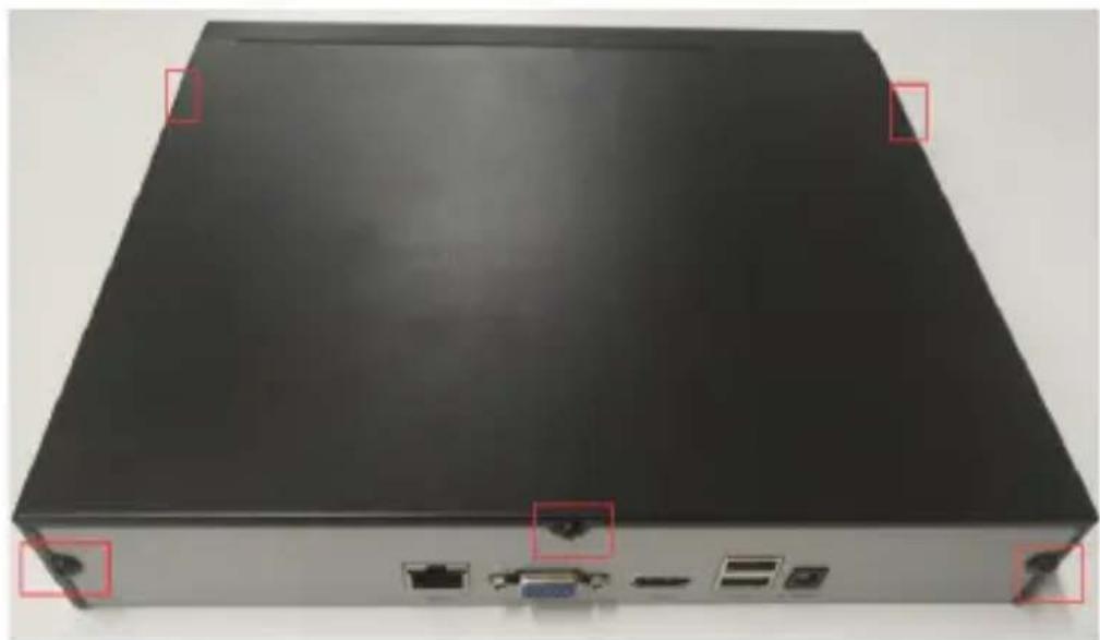
natural_image
Front view of a black server rack with ports and connectors, marked by red boxes (no visible text or symbols)2) Insert the hard disk along the slot and tighten the screws.
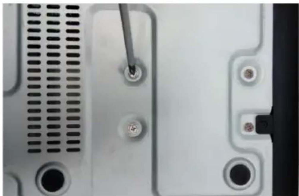
natural_image
Close-up of a computer monitor front panel showing screw holes and a screwdriver inserted (no text or symbols visible)3) Connect the device to the power and the data cable to the NVR and HDD.
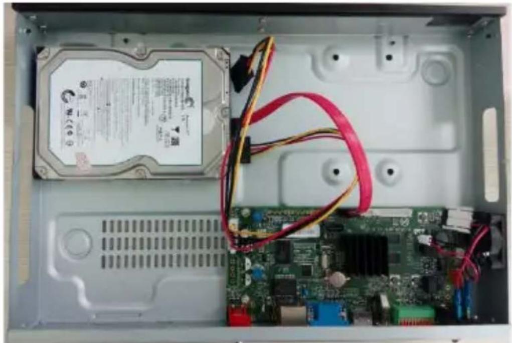
natural_image
Interior view of an open computer case showing a hard disk, circuit board, and cable (no visible text or symbols)4) Reinstall the cover and tighten the screws.
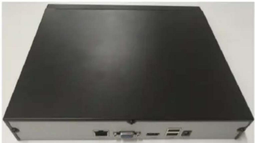
natural_image
Front view of a black server rack unit with ports and connectors (no visible text or labels)
NVR with 4 or 8 HDDs.
Steps :
1) Remove the cover from the NVR by untightening the screws on the side and rear panels.
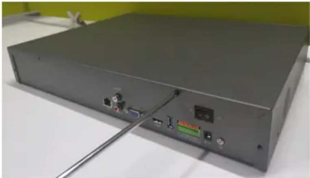
natural_image
Back view of a gray server rack with ports and connectors, no visible text or symbols2) Fix the HDD with screws at the bottom.
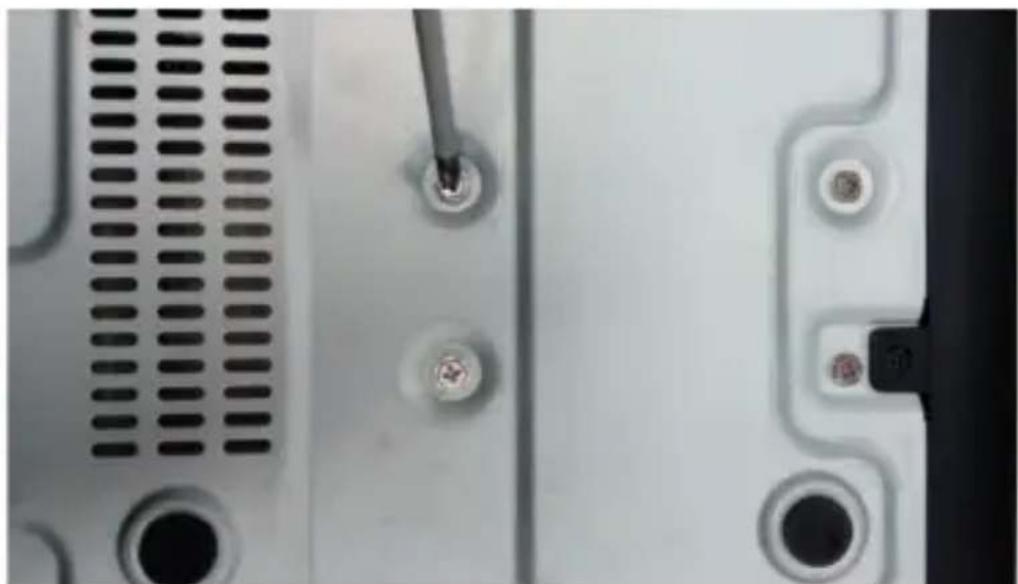
natural_image
Close-up of a computer drive with screw and socket components (no visible text or symbols)3) Connect the device to the power and the data cable to the NVR and HDD.
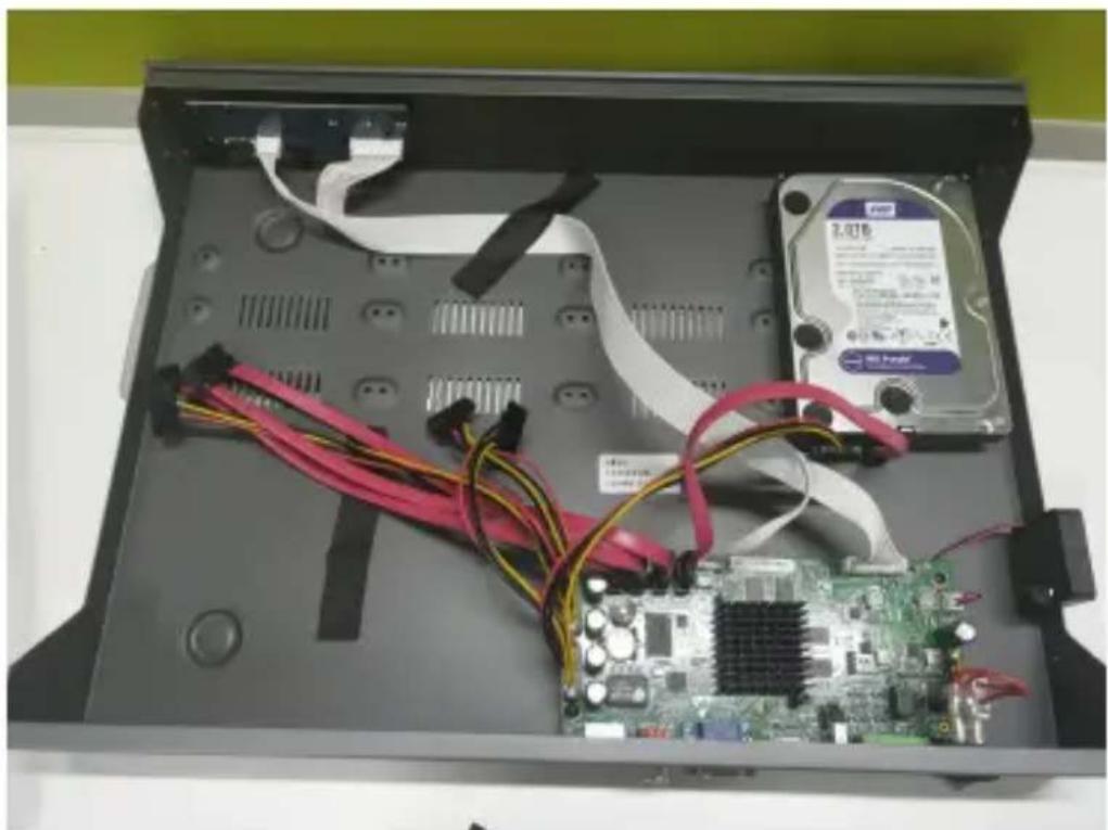
natural_image
Interior view of an open computer case showing a hard disk, CPU socket, and motherboard with visible wiring (no text or symbols)4) Reinstall the cover and tighten the screws.
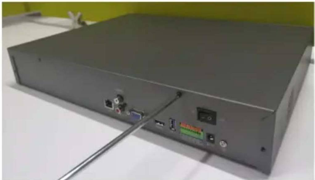
natural_image
Back view of a gray server rack with ports and connectors, no visible text or symbolsChapter 2 Getting Started
2.1 Starting up and Shutting down
2.1.1 Starting up
Plug in the power cord, press the power switch, then the power indicator should light up, and the device will start to boot. After the device starts, the video output mode is set as multiple-screen by default.
2.1.2 Shutting down
Option 1: Press the power key on the rear panel to shut the device down (should be supported by the device).
Option 2: Click on Start → Shutdown → Confirm ( 😊
Prompt: It is recommended to use this way, in order to avoid damages when the device is suddenly powered down.)
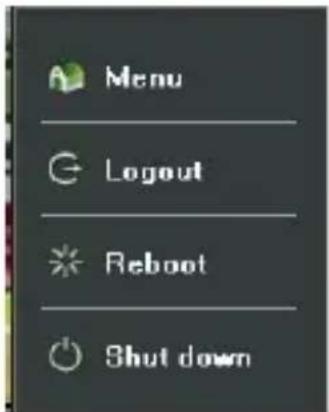
Figure 2.1 Shutdown Menu
2.2 Logging in
If NVR first start-up or has logged out, you must log in to the device before operating the menu and other functions, as shown in Figure 2.2.
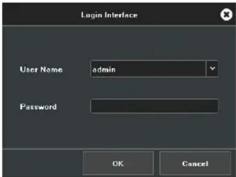
Figure 2.2 Login Interface
Steps:
1) Click on the Start button on the Lower left corner of the
screen.
2) Click on the Login button from the pop-up menu.
3) Input the password on the pop-up interface (Default password: 123456).
4) Click on OK to log into the system.
2.3 Using the Guide
The guide starts immediately after the login, as shown in Figure 2.3.
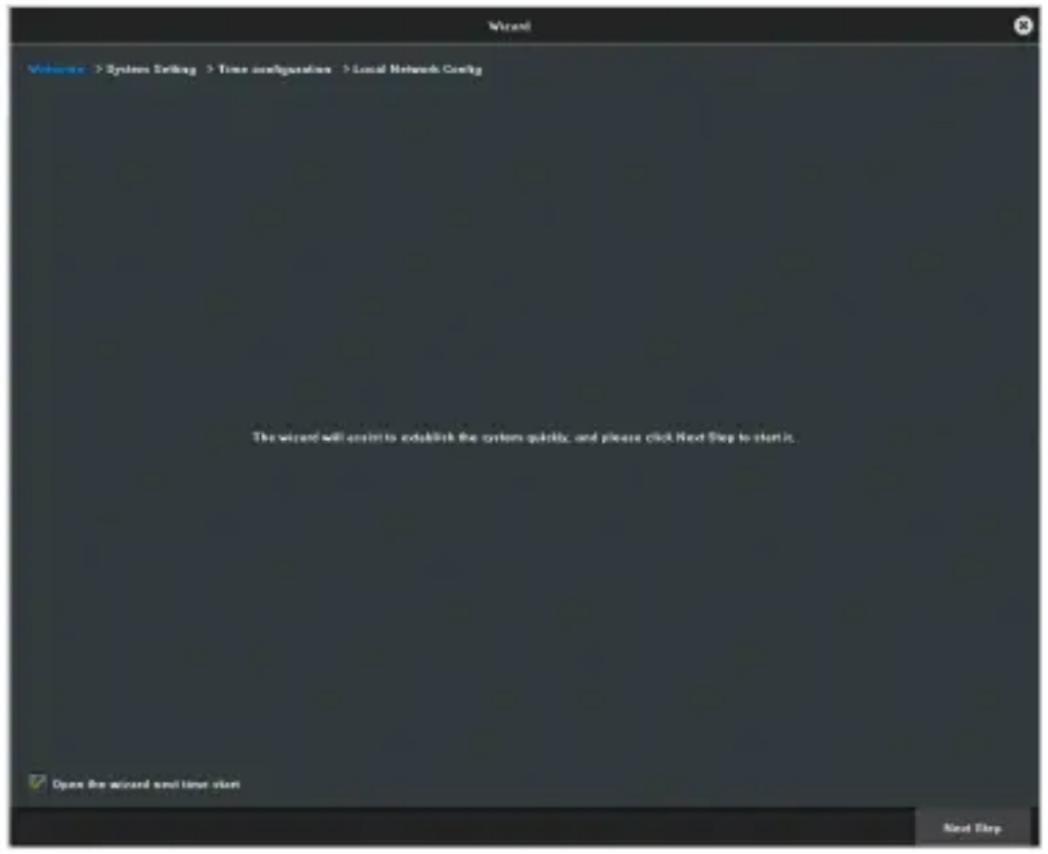
Figure 2.3 Wizard
Operating the guide
1) The system will guide you through some basic setup of the NVR. If you do not want to use the guide right now, click on the ✗ button. You may also choose to use the guide next time by unchecking the “Open the Wizard next time start” check-box.
2) Click on the Next step button to enter the system setting interface, as shown in Figure 2.4.
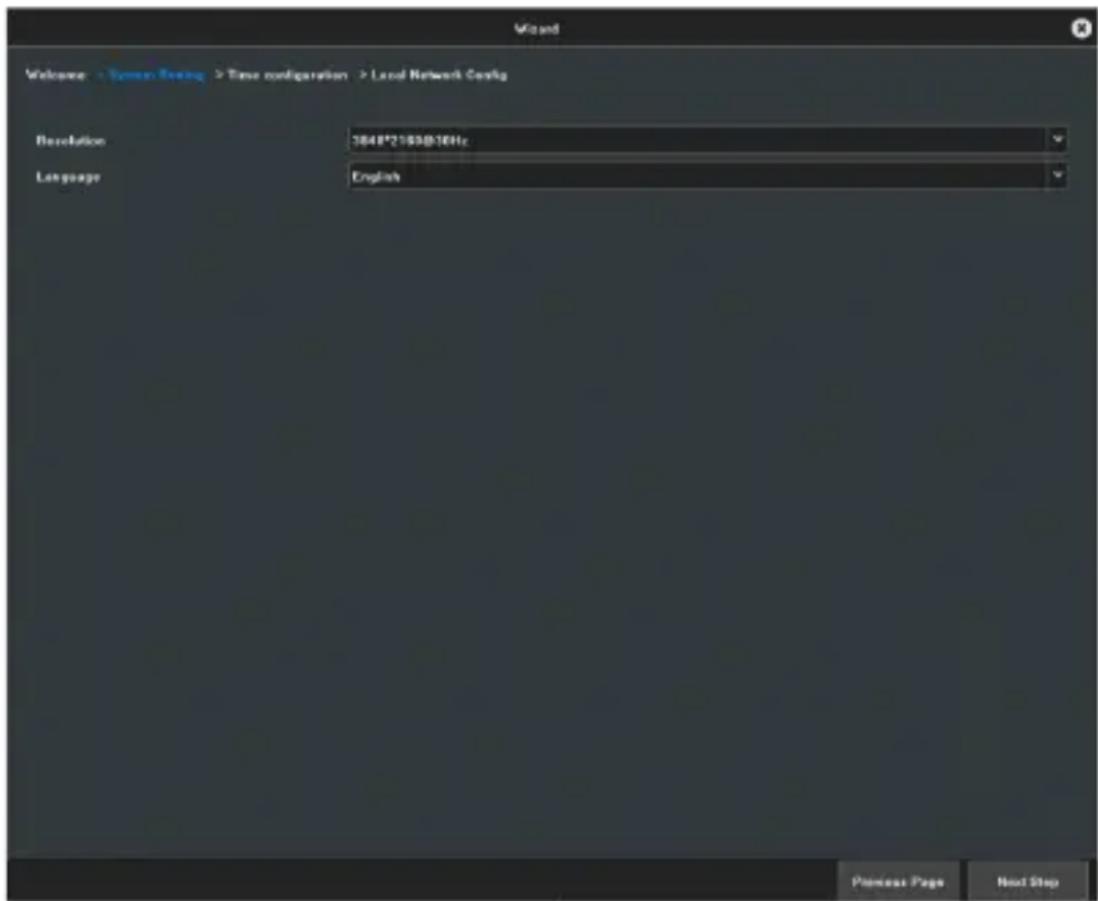
Figure 2.4 System Settings
3) After setting the display and language, click on the Next step button to enter the Time configuration interface, as shown in Figure 2.5.
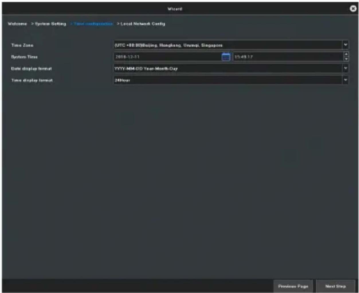
Figure 2.5 Time Configuration
4) After setting the time, click on the Next step button to enter the Local Network Config interface, as shown in Figure 2.6.
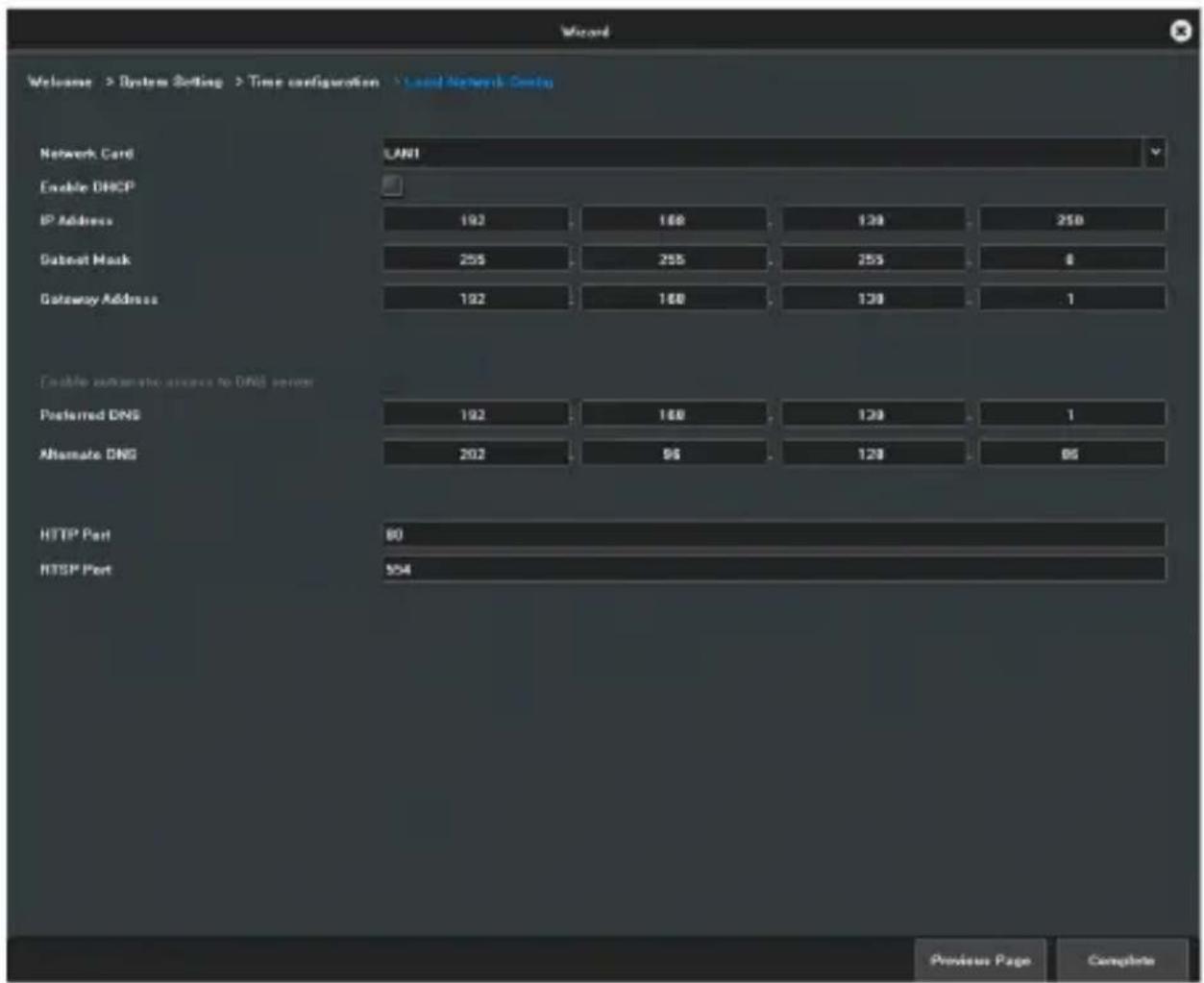
Figure 2.6 Local Network Config
5) Click on Complete button to finish the wizard.
2.4 Menu operations
After successful login, you may set the system accordingly on the main Menu interface by clicking your right mouse button as shown in Figure 2.7.
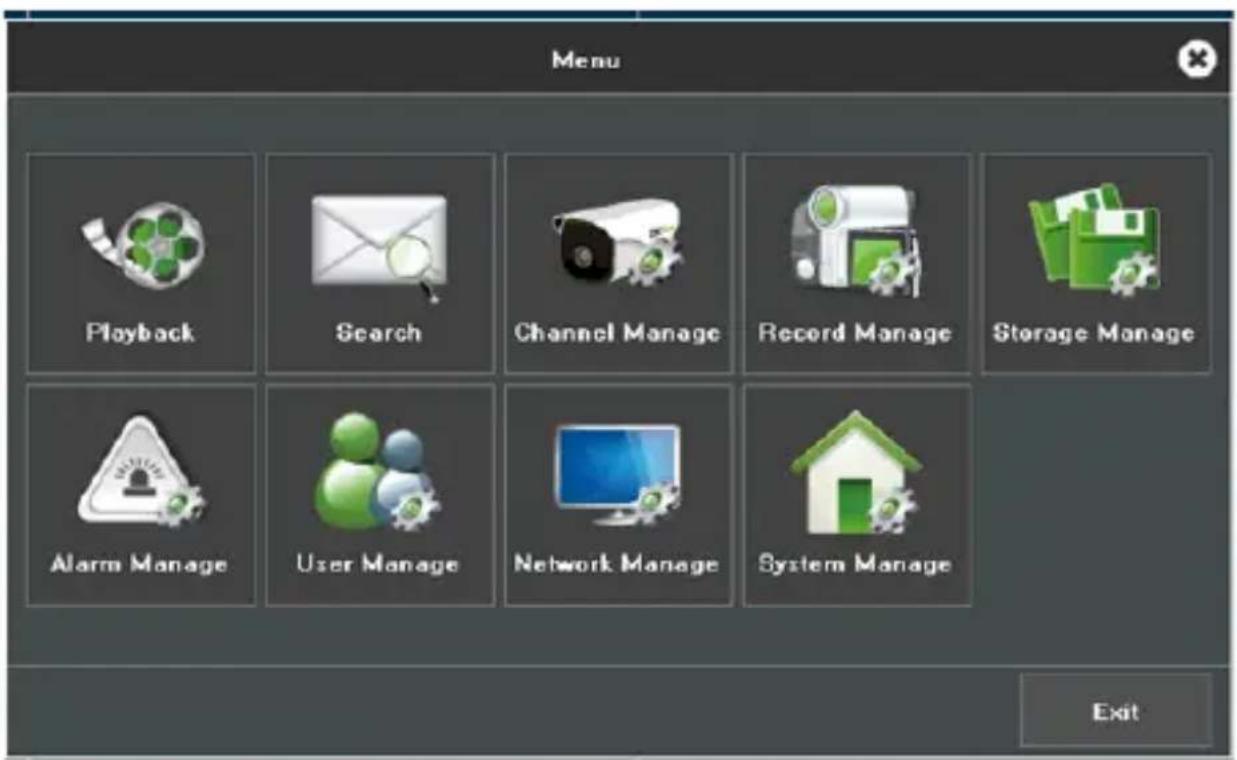
Figure 2.7 Main Menu Operations
2.4.1 Setup
Click on the Start icon, then the interface as show in Figure 2.8 will pop up.
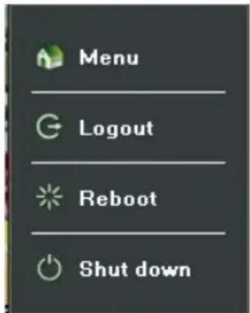
Figure 2.8 Setting Up
1) Logout: Click on the Logout button to log off.
2) Reboot: Click on the Reboot button and confirm, then the device will automatically reboot.
3) Shutdown: Click on the Shutdown button and confirm, then the device will automatically shut down.
Chapter 3 Preview
3.1 Introduction of Preview
Preview shows you the video image obtaining from each camera in real-time. The NVR will automatically enter live video mode when turned on, as shown in Figure 3.1.
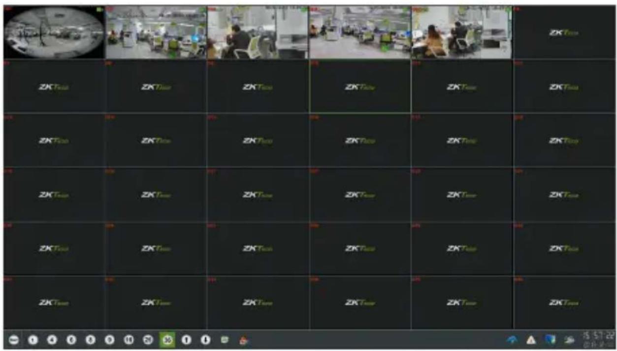
Figure 3.1 Preview Interface
Channel preview icons
In the preview mode, there are hidden icons on the interface of each channel, which will appear when you move the cursor to the bottom of the window.
 |  |  |  |  |  |  |  |  |
| Icons | Descriptions | Icons | Descriptions | |||||
| Open/ close PTZ | Show/ hide smart detection | |||||||
| Snapshots | Turn voice intercom on/off | |||||||
| Turn audio on/ off | Turn manual recording on/off | |||||||
| Instant playback | ||||||||
| Media parameters | ||||||||
| Face Detection | ||||||||
Table 3.1 Icons Descriptions
Media parameters: you may adjust the brightness, contrast, saturation and hue of the channel that the current mouse selected, one click to restore the default value when necessary, as shown in Figure 3.2.
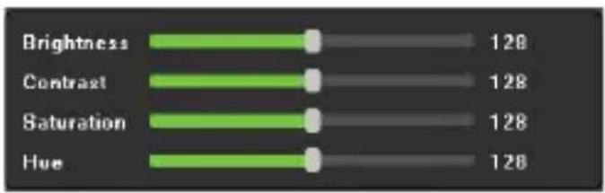
bar
| Category | Value | |---|---| | Brightness | 128 | | Contrast | 128 | | Saturation | 128 | | Hue | 128 |Figure 3.2 Media Parameters
PTZ/ Preset/ Cruise/ Pattern:
Please confirm whether the related parameters is correctly set before controlling the PTZ. After setting up the parameters, select the channel to be controlled on the preview interface, then control the direction of the lens, focal length, focus, aperture amplification and narrow in PTZ operation interface, and adjust the speed of PTZ, as shown in Figure 3.3. For detailed operations of PTZ control part, please see below.
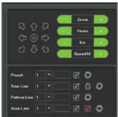
Figure 3.3 PTZ Control
3.2 Operations in Preview Mode
In preview mode, there are many functions provided, which are listed below.
On the bottom-right corner, there are some icons of real-time information, as shown in Figure 3.4.

Figure 3.4 Real-time Information
1) P2P information
When you click on 📄, the interface will pop up the P2P information, as shown in Figure 3.5.
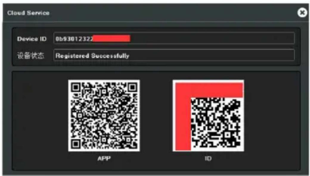
Figure 3.5 P2P Information
2) Real-time alarm information
When you click on , the interface will pop up the alarm information, as shown in Figure 3.6.
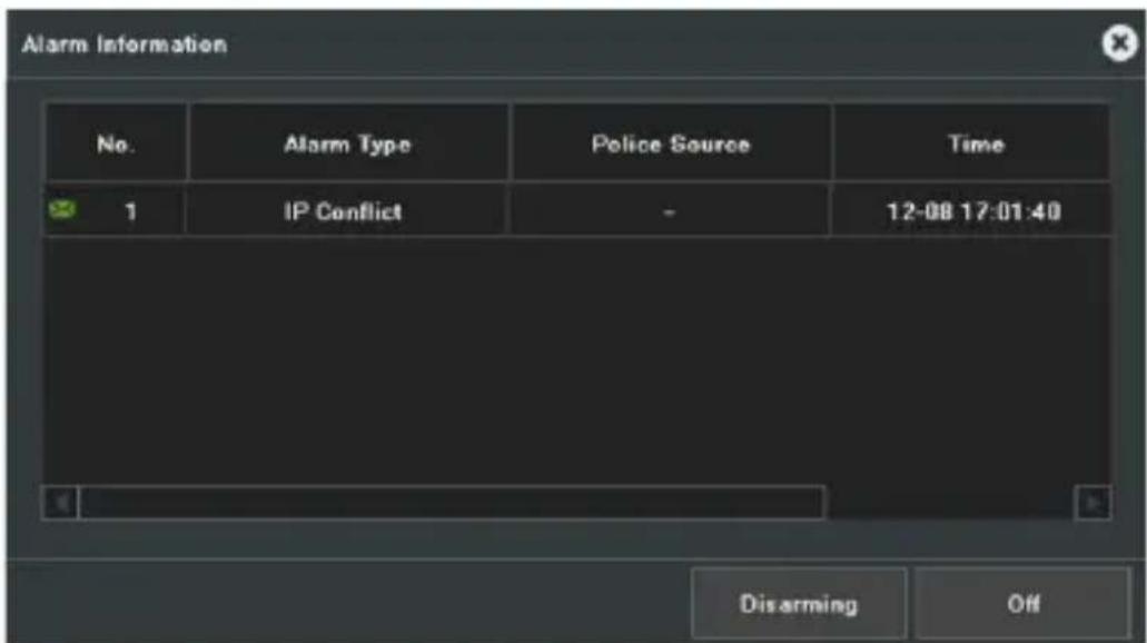
Figure 3.6 Alarm Information
3) Network Information
When you click on , the interface will pop up the Network information, as shown in Figure 3.7.
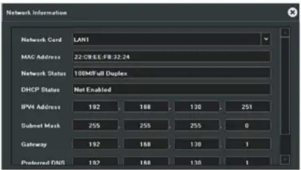
Figure 3.7 Network Information
4) System Sound
When you click on , the interface will pop up the system sound, as shown in Figure 3.8.
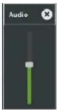
Figure 3.8 System Sound
5) Other functions
| Icons | Descriptions | Icons | Descriptions |
 | Single screen |  | 4 screens |
 | 6 screens |  | 8 screens |
 | 9 screens |  | 16 screens |
 | 25 screens |  | 36 screens |
 | 64 screens |  | Audio adjustment |
 | Cruise on settings |  | Linkage preview |
 | Page up |  | Page down |
Table 3.2 Descriptions of Other Functions
3.3 Using the Mouse in Preview
When you right-click, you can open the shortcut menu as shown in Figure 3.9.
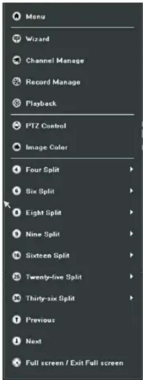
Figure 3.9 Shortcut Menu
| Names Descriptions | |
| Menu Access the main menu | |
| Wizard | Access the wizard interface. |
| Channel Manage | Quick access to the channel management interface. |
| Record Manage | Quick access to the record management interface. |
| Playback | Quick access to the playback interface. |
| PTZ Control | Access the PTZ interface. |
| Image color | Quick access to the image color interface. |
| 4-split-screen | Select and access the 4-screen mode. |
| 6-split-screen | Select and access the 6-screen mode. |
| 8-split-screen | Select and access the 8-screen mode. |
| 9-split-screen | Select and access the 9-screen mode. |
| 16-split-screen | Select and access the 16-screen mode. |
| 25-split-screen | Select and access the 25-screen mode. |
| 36-split-screen | Select and access the 36-screen mode. |
| Previous | Switch to the previous settings. |
| Next | Switch to the next settings. |
| Full Screen/Exit Full Screen | Quickly access/exit the full screen mode. |
Table 3.3 Descriptions of Right-click Functions
Chapter 4 Playback
4.1 Instant Playback
Purpose:
Play the recorded videos from a specific channel in the live video mode.
Steps:
Choose a channel in live video mode and click on the icon on the bottom of the channel, as shown in Figure 4.1.

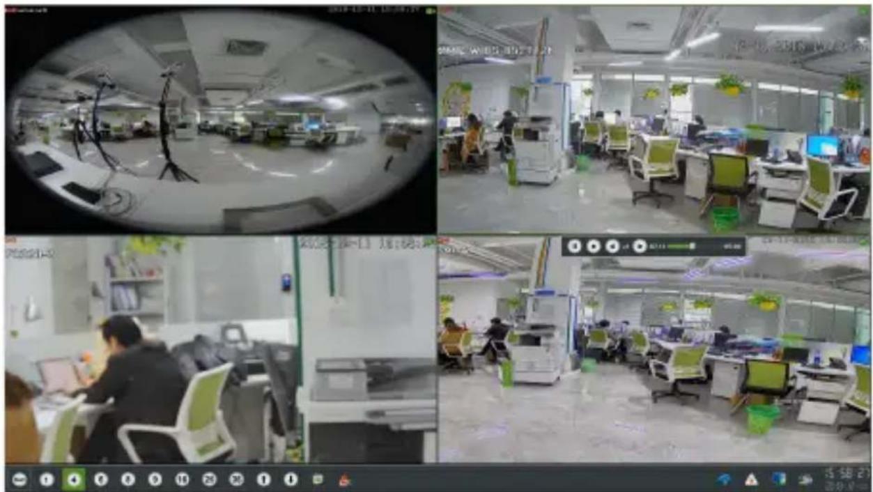
Figure 4.1 Instant Playback
4.2 Playback by Normal Search
4.2.1 Recording Playback
Click on the

icon to enter the playback interface, as shown in Figure 4.2.
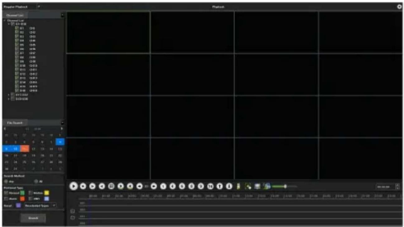
Play video recorded in specified time duration. Multi-channel simultaneous playback is supported.
Steps:
1) Enter the Playback interface.
2) Check the check-box(es) of the desired channel(s) in the channel list and then double-click to select a date on the calendar.
3) Click on the ▶ button to start playback, as shown in Figure 4.3.
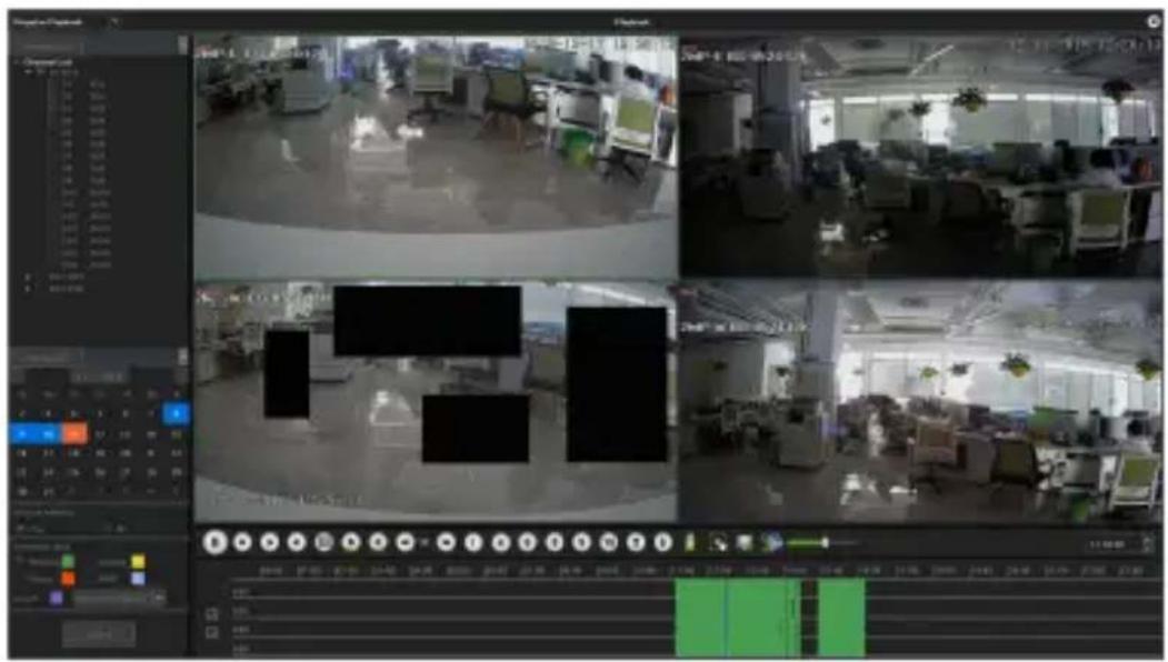
Figure 4.3 Video Playback
Notes:
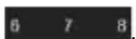
If there are video files recorded by the camera on a specific day, the icon representing that day shown in the calendar will be displayed as 6 7 8. Otherwise, it is displayed as

Playback Interface
You may use the toolbar in the bottom part of the playback interface to control the playing, as shown in Figure 4.4.

Figure 4.4 Playback Toolbar
| Buttons | Descriptions Button | Descriptions | |
 | Play/ pause |  | Stop |
 | Fast forward |  | Rewind |
 | Single frame |  | 30 seconds forward/backward |
 | Slow down |  | Speed up |
 | Single screen |  | 4 screens |
 | 6 screens |  | 8 screens |
 | 9 screens |  | 16 screens |
 | Page up/page down |  | Backup |
 | Capture |  | Hide/ show the time bar |
 | On/Off Audio |  | Change the time bar |
Table 4.1 Descriptions of Toolbar Icons
4.2.2 Playback by Event Search
Purpose:
Play recorded files on one or several channels searched out by event type (e.g. alarm detection, motion), as shown in Figure 4.5.
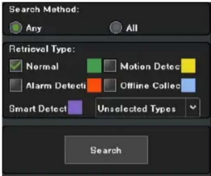
Figure 4.5 Event Search
Steps:
1) Enter the playback interface.
2) Select the retrieving type: count alarm, motion, across the line, regional, alarm detection and object left/loss...
3) Click on the Search button to obtain information of the results.
4) Click on the ▶ button to play the file back.
4.2.3 Playback of Pictures
Purpose:
The captured pictures stored in the HDDs of the device can be searched and viewed, as shown in Figure 4.6.
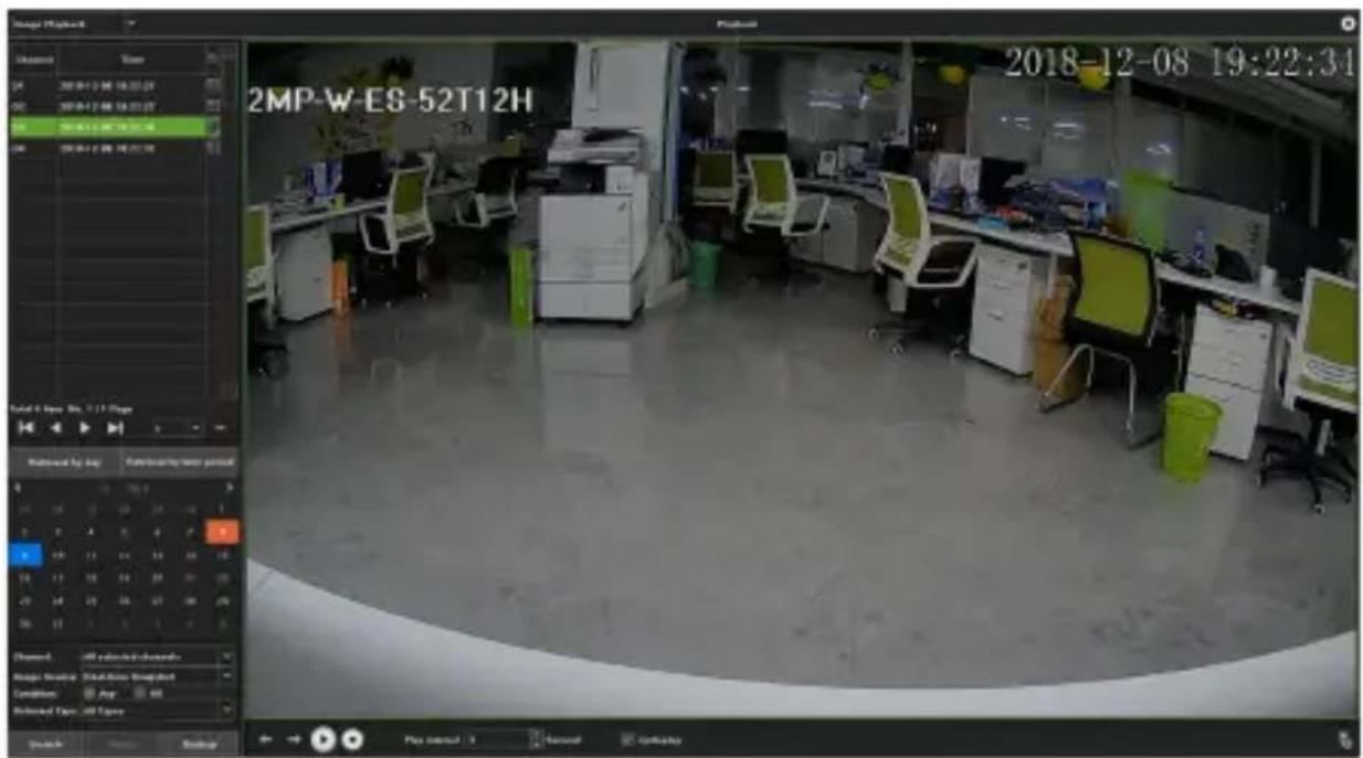
Figure 4.6 Picture Playback
Steps:
1) Enter the playback interface.
2) Select playback modes: image playback.
3) Select "Search by day" or "Search by time".
4) Select picture source: IPC snapshot (preview snapshot) or playback snapshot.
5) Choose condition: Meet random or Meet all.
6) Select Retrieving type.
7) Select "Search Channel".
8) Click on the Search button to search for the captured pictures.
9) Check the check-box behind the picture shown, then click to view the picture.
10) The toolbar in the bottom of the playback interface can be used to control the playing.
| Buttons | Functions | Buttons | Functions |
 | Play/ stop |  | Stop |
 | Next picture |  | Last picture |
Table 4.2 Descriptions of Playback Toolbar
4.2.4 Playback of External Files
Purpose:
Perform operations according to the following steps to look up and play back files in the external devices, as shown in Figure 4.7.
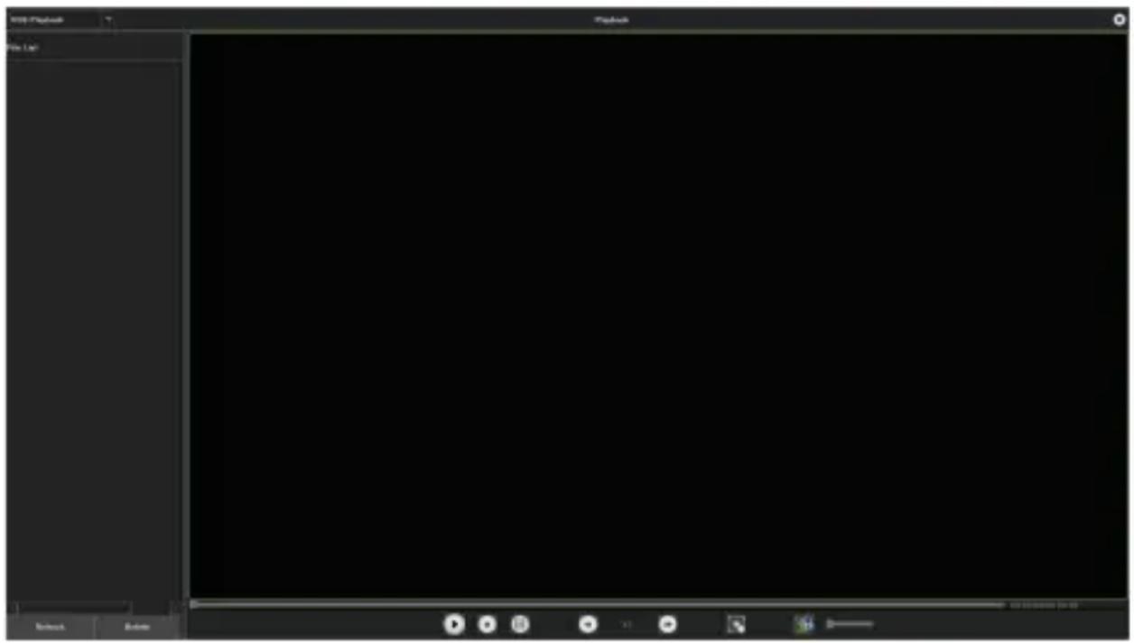
Figure 4.7 USB Playback Interface
Steps:
1) Enter the playback interface.
2) Select playback modes: USB playback.
3) Click on the Refresh button to refresh the list.
4) Select and click on the ▶ button to play the video back.
4.3 Playback Backup
Purpose:
The video stored on the hard disk can be exported to a USB drive or removable hard disk, as shown in Figure 4.8. Here are the steps.
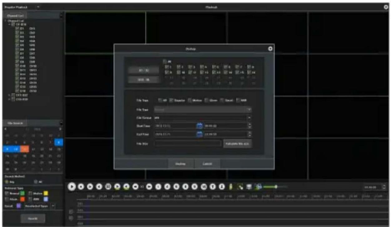
Figure 4.8 Backup
Steps:
1) Insert a USB drive or removable hard disk into the NVR's USB port.
2) Enter the Playback interface.
3) Check the check-box(es) of the desired channel(s) in the
channel list
4) Click on the 📋 button to enter the backup interface as shown in Figure 4.9.

Figure 4.9 Backup Interface
5) Select the starting and ending time, and make sure the backup time is correct, or you may click on the time and date to modify them.
6) Click on the Backup button and select the USB drive or removable hard disk, then select the folder and click on
Backup button.
7) A backup progress bar will appear. Wait until the system finish reading. Then, pull out your USB drive or removable hard disk.
Chapter 5 PTZ Controls
5.1 Setting PTZ Preset, Cruise, Pattern & Linear Scan
Before starting:
Please make sure that the preset, cruise and pattern should be supported by PTZ protocols, as shown in Figure 5.1.
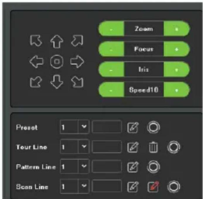
Figure 5.1 Interface of PTZ Settings
5.1.1 Preset Settings
Follow the steps below to set the preset position that you want the PTZ camera to be in when an event occurs.
Steps:
1) Use the directional button to turn the camera to the position where you want to set a preset, and the zoom and focus operations can be recorded in the preset as well.
2) After setting the name of a preset, click on the button to save the changes. Repeat the above steps to save more presets.
5.1.2 Cruise Settings
Purpose:
You may set a cruise to move the PTZ to different locations and have the camera stay there for a set duration before moving on to the next location. The locations are corresponding to the presets. The presets can be set following the steps mentioned in Preset Settings above.
Steps:
1) Select the number of cruises in the drop-down list of cruise.
2) Click on the

button to add key points for cruise, as shown in Figure 5.2.
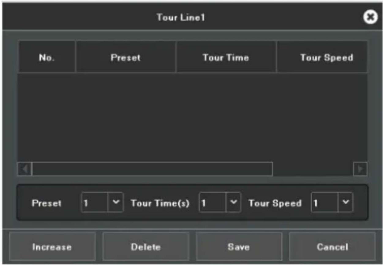
Figure 5.2 Tour Line
3) Configure parameters of key points, such as the number of a key point, duration of staying for one key point and speed of cruise. The key point is corresponding to the preset. The Key Point No. determines the cruise order of the PTZ. The Cruise time refers to the time span to stay at the corresponding key point. The Cruise Speed defines the speed at which the PTZ will move from one key point
to the next one.
4) Click on the Add button to add the next key point to the patrol.
5) When finished, click on the Exit button.
5.1.3 Pattern Settings
Purpose:
Patterns can be set by recording the movement of the PTZ. You can call the pattern to make the PTZ moves according to the predefined path.
Steps:
1) Choose a pattern number in the drop-down list.
2) Click on the button to begin and click on corresponding buttons in the control panel to move the PTZ camera, then click on the button to end. Then, the movement of the PTZ is recorded.
5.1.4 Linear Scan Settings
Steps:
1) Select a number, use the directional button to spin the
camera to the location where you want to set a starting
point, then click on the button.
2) Spin the camera to the location where you want to set an ending point, then click on the button.
3) Click on the button, then the PTZ camera will spin from the starting point to the ending point.
Chapter 6 Search
Purpose:
The record files can be backed up to various devices, such as USB devices, including USB flash drives and USB HDDs.
Click on the icon to enter the local backup interface, as shown in Figure 6.1.
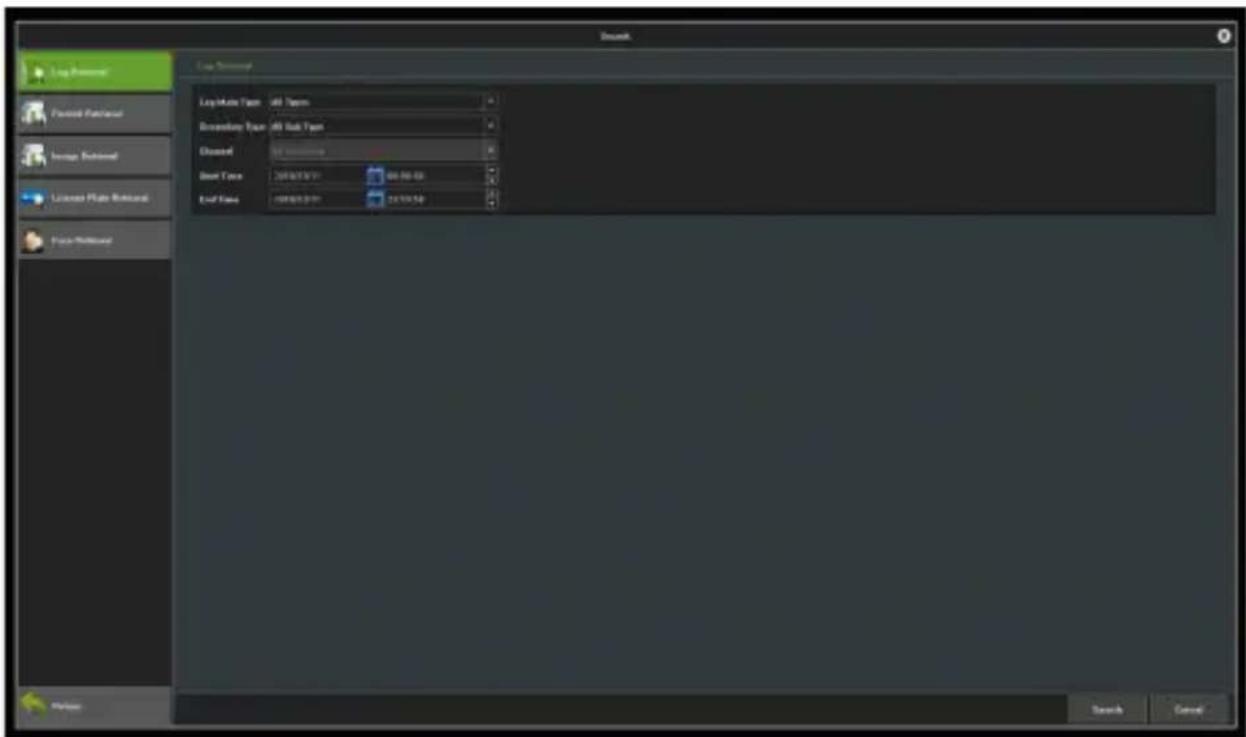
Figure 6.1 Search Interface
6.1 Log Retrieval
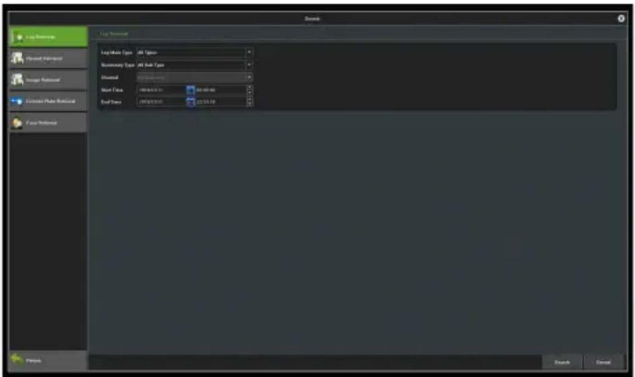
Figure 6.2 Log Retrieval Interface
Steps:
1) Set the type and time of file to backup.
2) Click on the Search button to view the file size.
3) Click on the Export All Log button to start the backup.
4) When finished, click on Confirm.
6.2 Image Retrieval
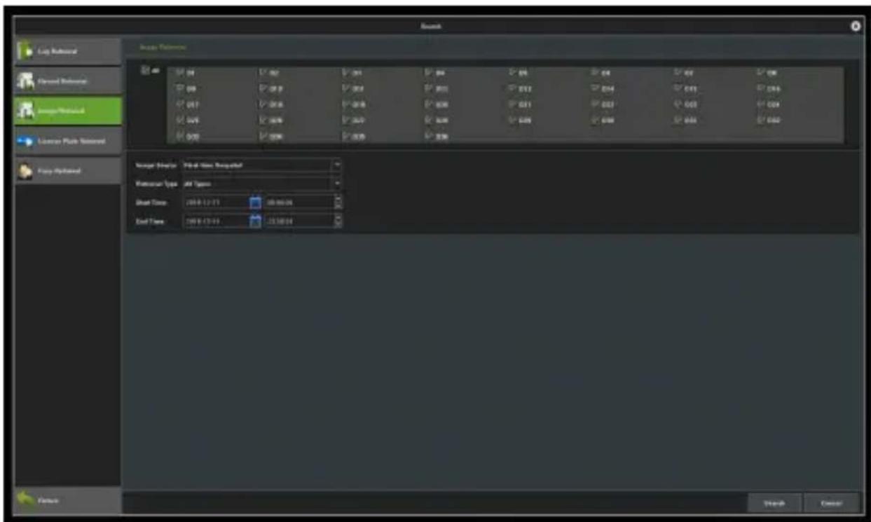
Figure 6.3 Interface of Image Retrieval
Steps:
1) Select channels to start backup.
2) Select the Image Source and Retrieval Type.
3) Set the time of file to backup.
4) Click on the Search button to view the file size.
Click on the Start Backup button to start the backup.
6.3 Video Retrieval
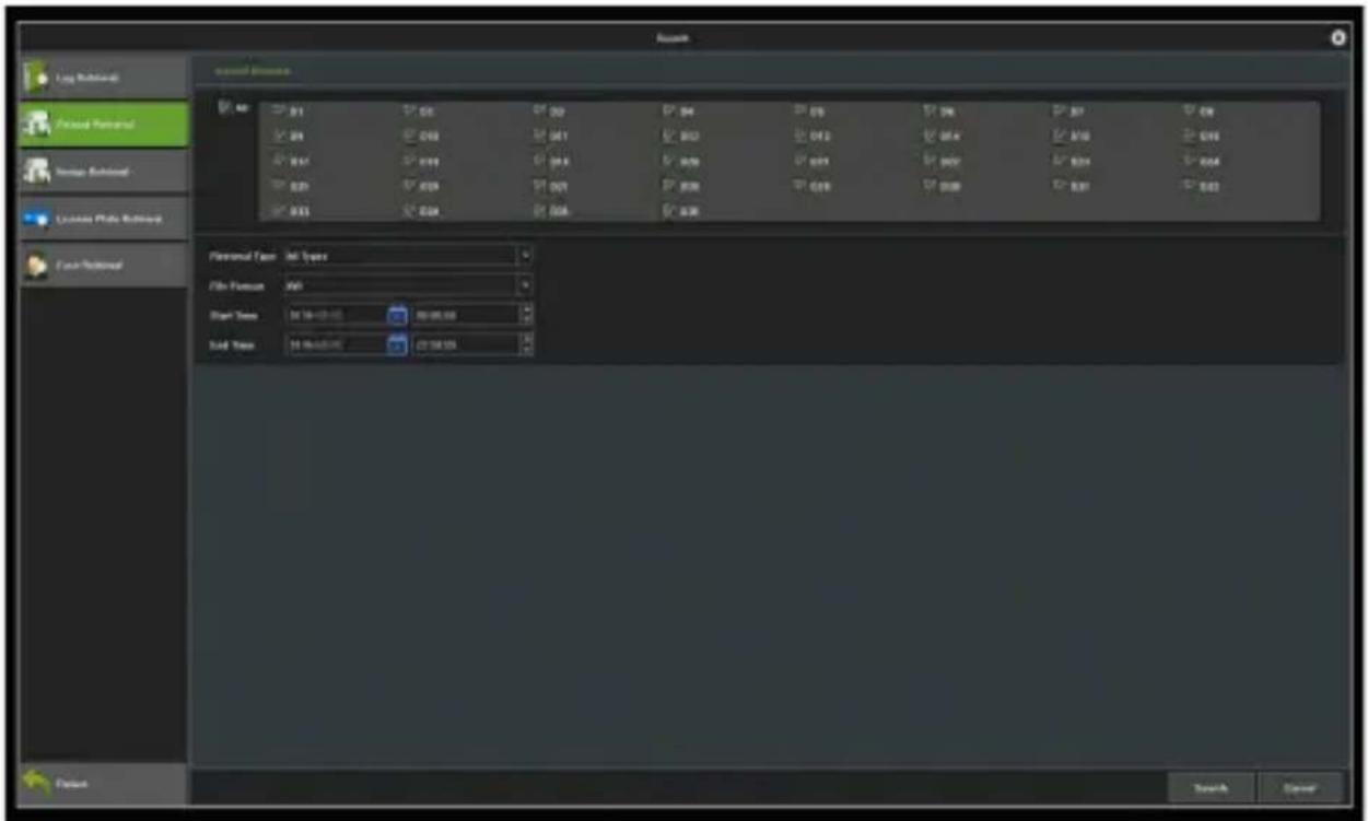
Figure 6.4 Interface of Video Backup
Steps:
1) Select channels to start backup.
2) Set the time of file to backup.
3) Select a file format.
4) Click on the Search button to view the file size.
5) Click on the Start Backup button to start the backup, as shown in the following picture.
6) When finished, click on Confirm.
Chapter 7 Channel Management
7.1 Adding IP Cameras
Purpose:
Before obtaining a live video or recording any videos, you should add the network cameras to the connection list of the device.
Before starting:
Ensure the network connection is valid and correct, and the IP camera to be added has already been activated.
Steps:
1) Click on the icon, enter the "Channel Information" interface, as shown in Figure 7.1.
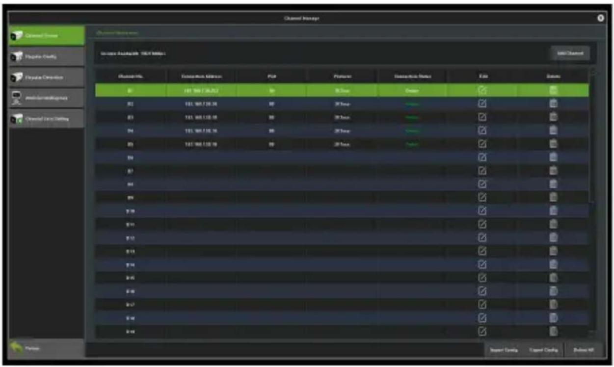
Figure 7.1 Interface of Quick Adding of IP Cameras
2) Click on Add Channel, then the system will automatically search for all IP cameras connected to the NVR.
3) You may click on the Refresh button to refresh the list of online IP cameras manually. Select a detected IP camera and click on OK to add it to the connection list directly, as shown in Figure 7.2.
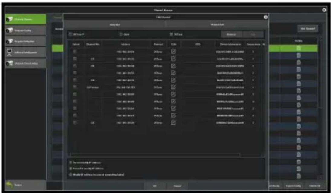
Figure 7.2 Add Channel(s)
4) Or, you may edit the parameters in the corresponding text field to add an IP camera, then click on Save to add it to the connection list, as shown in Figure 7.3.
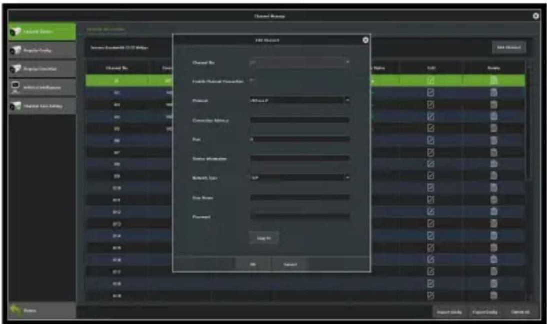
Figure 7.3 Interface of Custom Adding of IP Cameras
7.2 Regular Configuration
7.2.1 Channel Display
Purpose:
You can configure the OSD (On-screen Display) settings for the camera, including the camera name, date/time, and so on.
Steps:
1) Enter the channel display configuration interface.
Channel Management → Regular Configuration → Channel Display
2) Select a channel to which the desired camera is connected and start to configure OSD settings.
3) Setting the "Local Channel Name"
Tick the check-box in front of "Show Local Channel Name", then enter the name of the local channel in the text field.
Click on the Save button, then the name input will be shown on the screen. You may click and drag the text frame on the window with your mouse to adjust the OSD position.
4) Setting the "IP Camera Name" (should be supported by the camera)
Tick the check-box in front of "Show Channel Name", then enter the channel name in the text field.
Click on Save, the name input will be shown on the screen. You may to click and drag the text frame on the window with your mouse to adjust the OSD position, as shown in Figure 7.4.
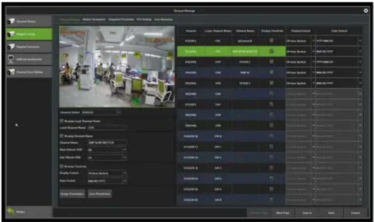
Figure 7.4 Interface of OSD Configuration
5) Select the date and time format (should be supported by the camera).
6) Image parameters: adjust the brightness, contrast,
saturation and hue of the channel, as shown in Figure 7.5.
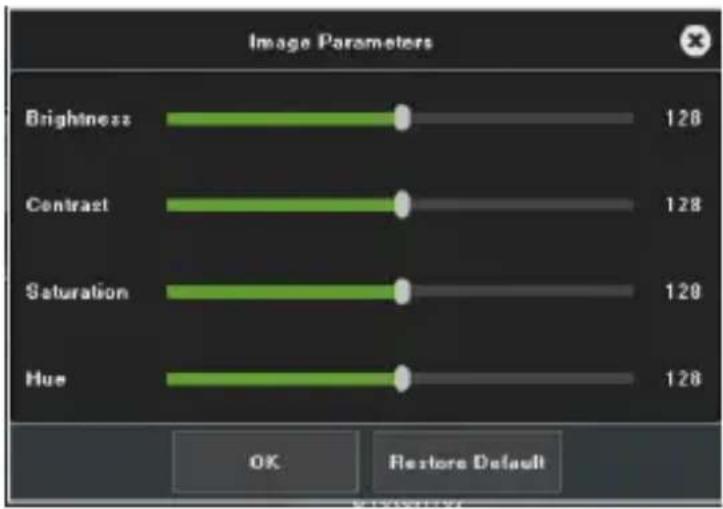
Figure 7.5 Interface of Image Settings
➢ lens parameters: set parameters for the channel camera lens, as shown in Figure 7.6.
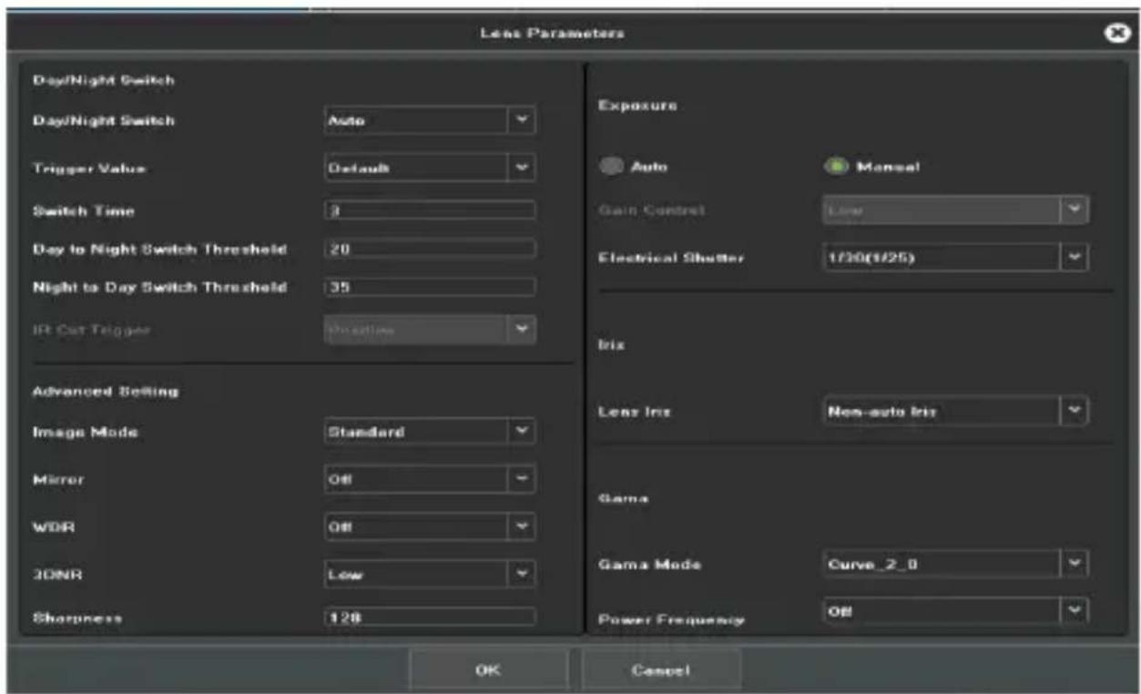
Figure 7.6 Interface of Camera Lens Parameters Settings
➢ Click on Save to save the settings.
7.2.2 Media Parameters
Purpose:
Sometimes you need to edit the parameters for channel camera recordings for better image quality.
Steps:
1) Enter the interface of media parameters, as shown in Figure 7.7.
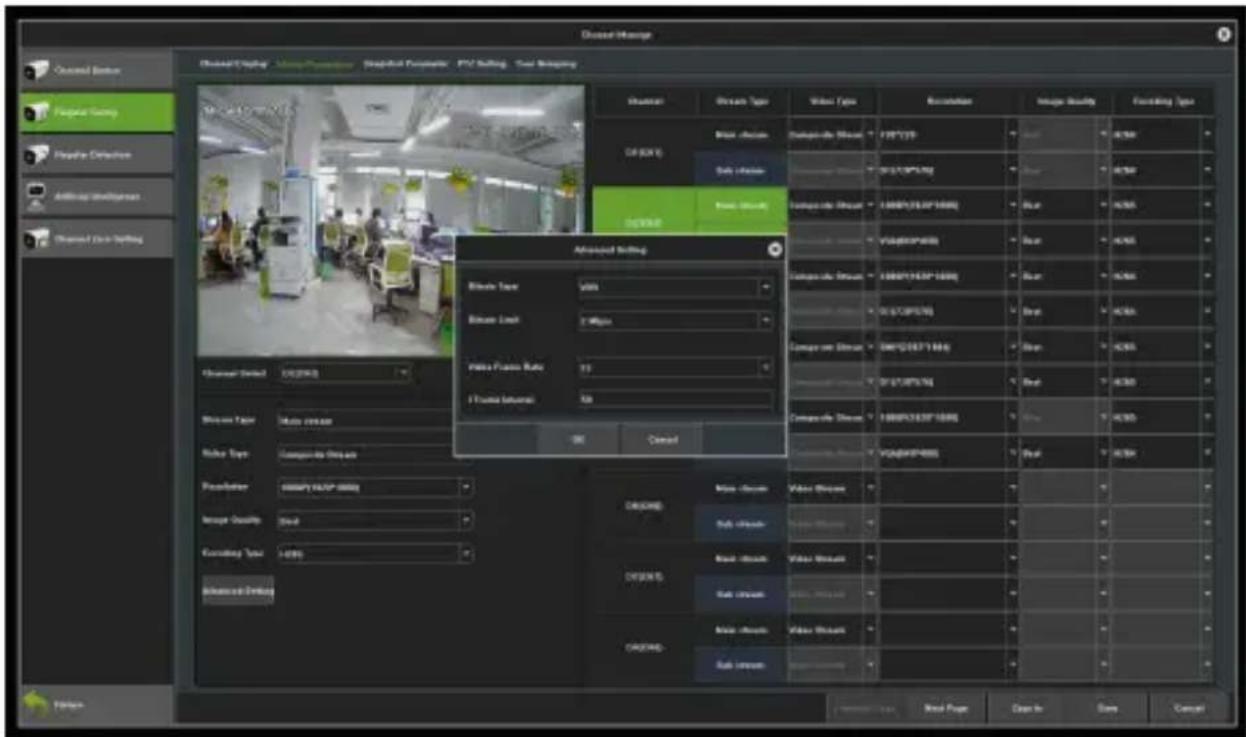
Figure 7.7 Recording Parameters
2) Set the video parameters:
Channel Select: Select the channel of camera to configure the
encoding type.
Stream Type: Select main stream or sub stream.
Video type: Select the video type.
Resolution: Select the video resolution.
Image Quality: Select the image quality when using the
VBR(variable bitrate) encoding method.
Encoding type: Select H.264 or H.265
Advanced settings:
Bitrate Type: CBR and VBR available.
Bitrate: Set the bitrate.
Frame Rate: Select the frame rate.
3) Click on Save to save the settings.
7.2.3 Snapshot Parameters
You may set the resolution of the local snapshots and relevant parameters on this interface as shown in Figure 7.8 below.
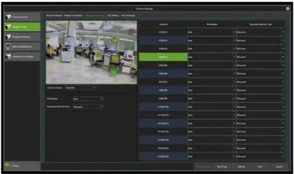
Figure 7.8 Snapshot Parameters
7.2.4 PTZ Settings
Follow the procedure below for setting the parameters for PTZ. The configuration of PTZ parameters should be completed before controlling the PTZ camera.
Steps:
1) Enter the PTZ Setting interface as shown in Figure 7.9.
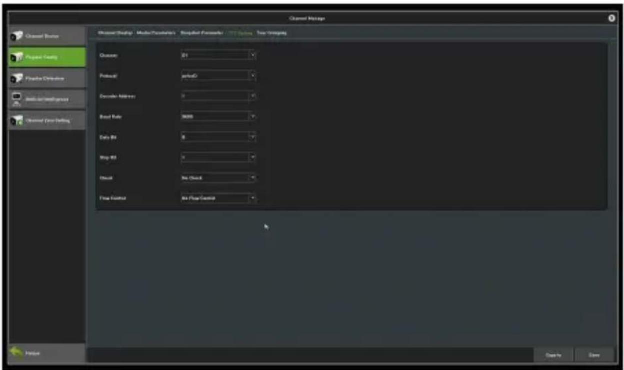
Figure 7.9 Interface of PTZ General Settings
2) Set the parameters for PTZ
Channel: Choose a channel.
Protocol: Choose the protocol for your PTZ.
Decoder Address: Choose a decoderaddress.
Baud Rate: Select a baud.
Data Bit: Select a data bit.
Stop Bit: Select a stop bit.
Parity: Select the verify, Non Parity by default.
Stream Control: Select the stream control; the default setting is "No Flow Control".
3) Click on Save to save the settings.
7.2.5 Tour Grouping
The role of setting tour Grouping is to group the channel and preview, can group according to a standard, as shown in Figure 7.10, that is group according to the region. The same channel can be divided into different groups as needed.
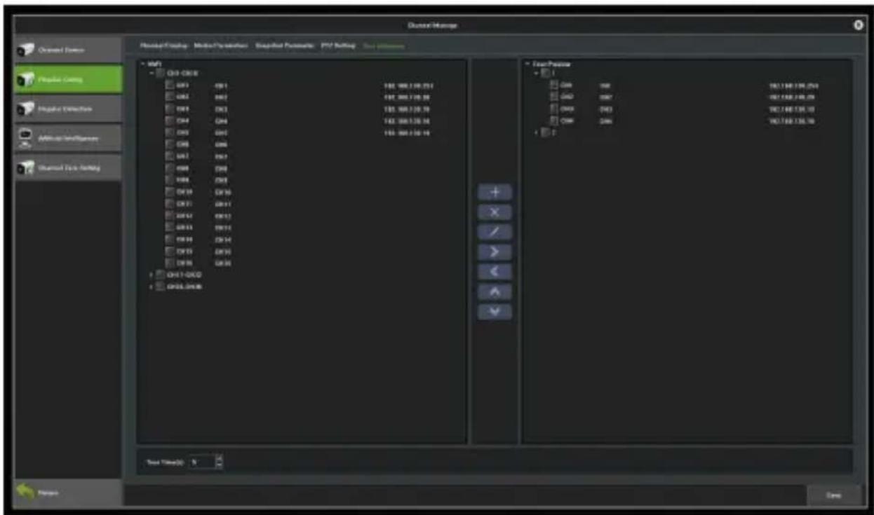
Figure 7.10 Interface of Tour Grouping settings
Functions of different icons are as shown below.
| Icons | Descriptions | Icons | Descriptions |
 | Create a group |  | Delete a group |
 | Modify the group name |  | Add channel |
 | Delate channel |  | Move up the group |
 | Move down the group | ||
Table 7.1 Functions of the Icons
7.3 Regular Detection
7.3.1 Motion Detection
On the motion detection interface as shown in Figure 7.11 below, you may set related parameters for motion detection.
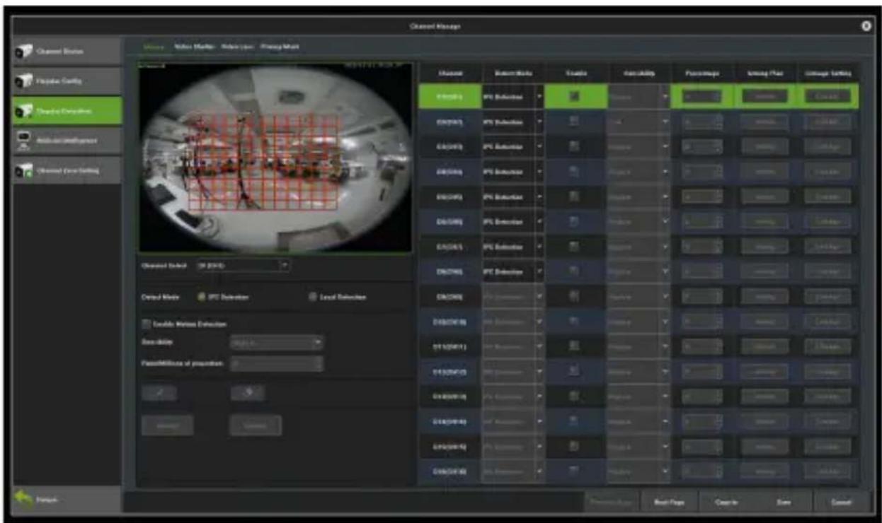
Figure 7.11 Motion Detection
Detect Mode: The default setting is "IPC Detection". You can switch mode to "Local Detection" if the NVR support this function.
Sensitivity: Change the accuracy of the motion detection trigger.
Zone settings: Left click and hold the mouse in the video area, drag it to the area that needs motion detection. The red plaid area is the selected motion detection area, as shown in Figure 7.12.
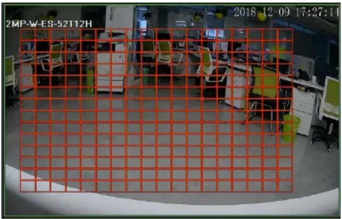
Figure 7.12 Zone Settings
Arming Plan: Set the schedule that needs arming, as shown in Figure 7.13.
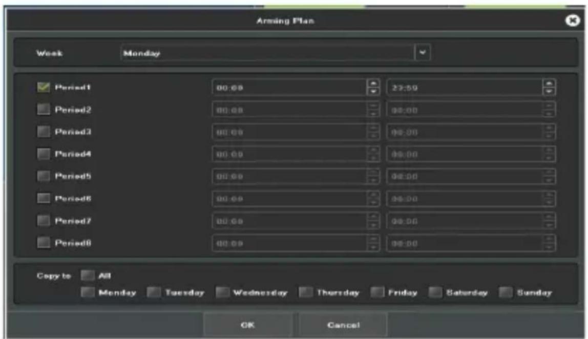
Figure 7.13 Arming Plan
Linkage Setting: Choose the mode that needs linkage, as shown in Figure 7.14.
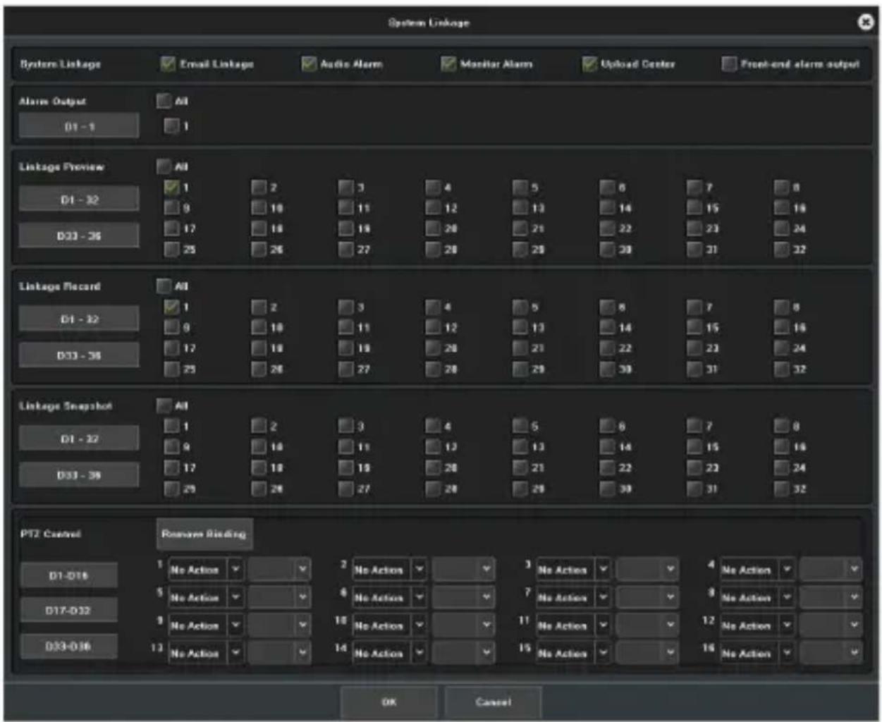
Figure 7.14 Linkage
Clear all: Click on to clear motion detection zone on the video area set before.
7.3.2 Video Lost
Below is the interface of video lost configuration.
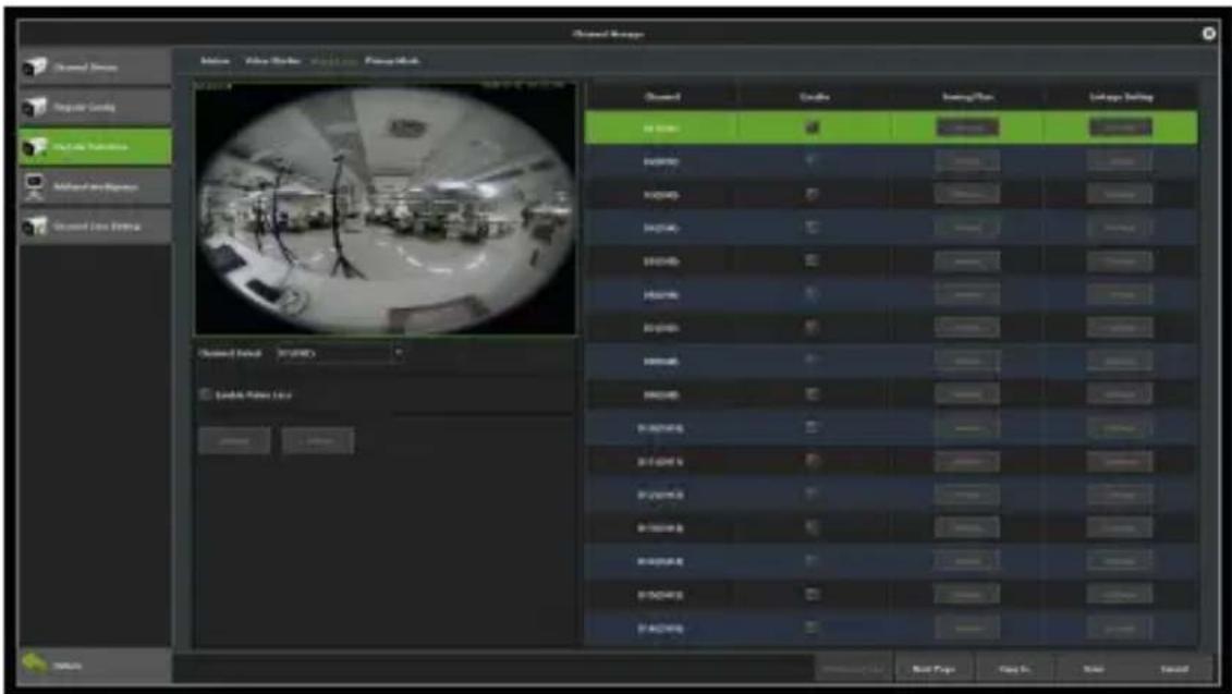
Figure 7.15 Video Loss
Channel: Choose a channel number.
Planning: Set the arming schedule for video loss, as shown in Figure 7.16.
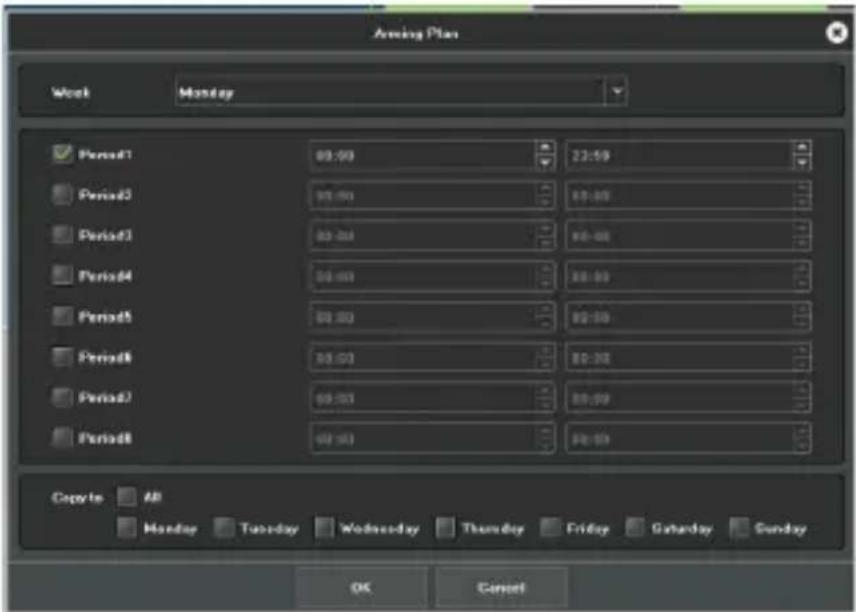
Figure 7.16 Planning
Linkage: Set the linkage mode, as shown in Figure 7.17.
![System Linkage System Linkage Email Linkage Audio Alarm Monitor Alarm Upload Center Linkage Preview AB 1 2 3 4 5 6 7 8 D1 - 32 3 10 11 12 13 14 15 16 D33 - 36 17 18 19 20 21 22 23 24 25 26 27 28 29 30 31 32 Linkage Record AB 1 2 3 4 5 6 7 8 D1 - 32 8 10 11 12 13 14 15 16 D33 - 36 17 18 19 20 21 22 23 24 25 26 27 28 29 30 31 32 Linkage Snapshot AB 1 2 3 4 5 6 7 8 D1 - 32 8 10 11 12 13 14 15 16 D33 - 36 17 18 19 20 21 22 23 24 25 26 27 28 29 30 [31] PTZ Control Reverse Binding No Action No Action No Action No Action No Action No Action No Action No Action No Action No Action No Action No Action No Action No Action No Action No Action No Action No Action No Action No Action No Action No Action No Action No Action No Action No Action No Action No Action No Action No Action No Action No Action No Action No Action NoAction](/content/2026/05/1000229/images/6a4c7cf35ea51f08a15d47b495e7c90ab92d949cda2418f505cdcfdc21aa08e8.jpg)
Figure 7.17 Linkage
7.3.3 Video Tampering
Purpose:
Trigger the alarm when the lens is covered and perform other response action(s) regarding the alarm.
Steps:
1) Enter the interface of video mask alarm of channel parameter and choose a channel which you want to set up a video mask alarm, as shown in Figure 7.18.
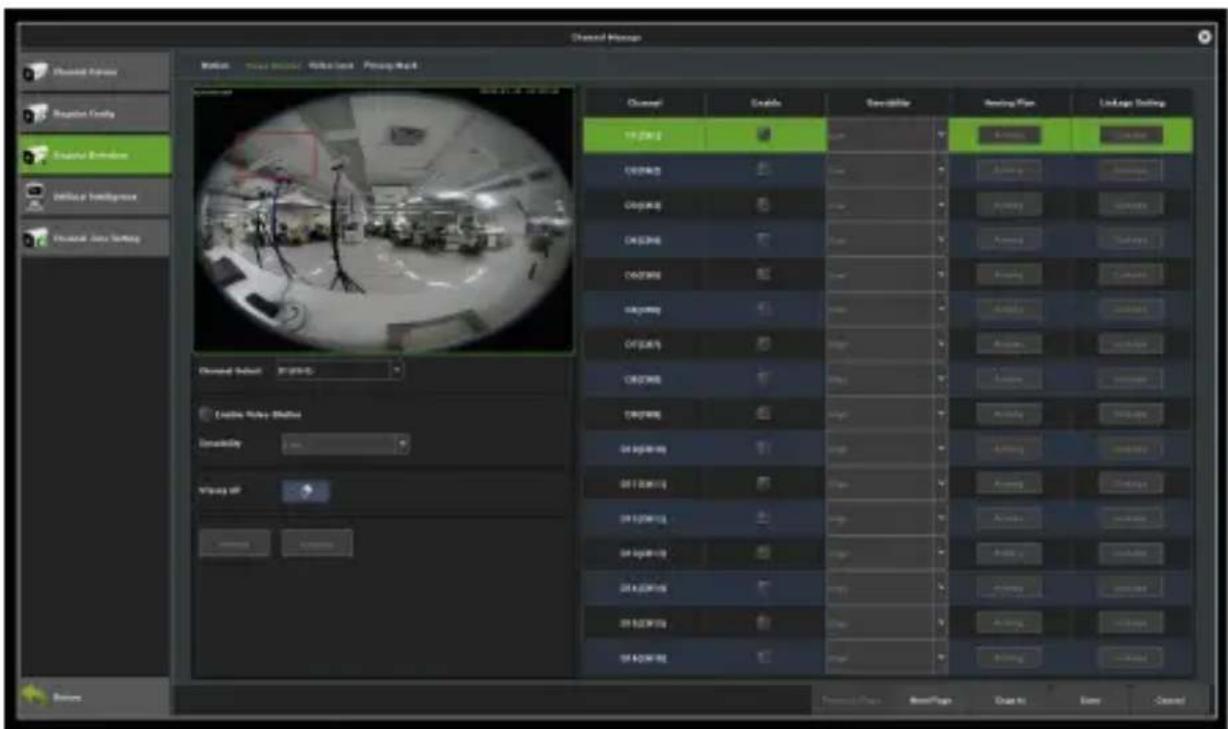
Figure 7.18 Video Tampering
2) Set the video mask alarm handling action of the channel.
Tick the check-box of Enable Video Tampering.
Select the sensitivity.
Use the mouse to draw an area that you want to detect video masks.
3) Set up the planning of the channel, as shown in Figure 7.19.
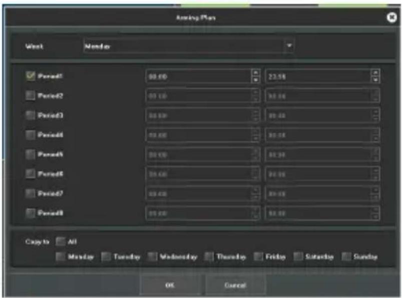
Figure 7.19 Planning
4) Set up the linkage operation of the channel, as shown in Figure 7.20.
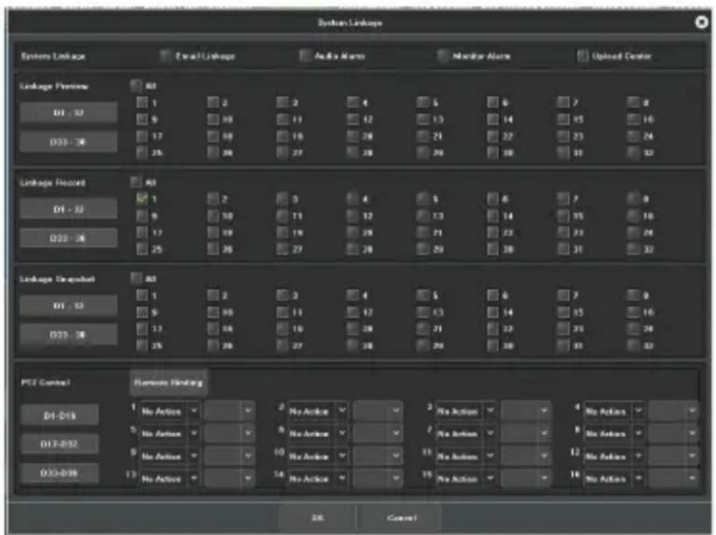
Figure 7.20 Linkage
5) Click on the Save button to save the settings.
Note: Onvif protocol does not support the video tampering feature.
7.3.4 Privacy Mask
Purpose:
You may configure the four-sided privacy mask zones that cannot be viewed by the operator. The privacy mask can prevent certain surveillance areas from being viewed or recorded.
Steps:
1) Enter the Privacy Mask Settings interface, as shown in Figure 7.21.
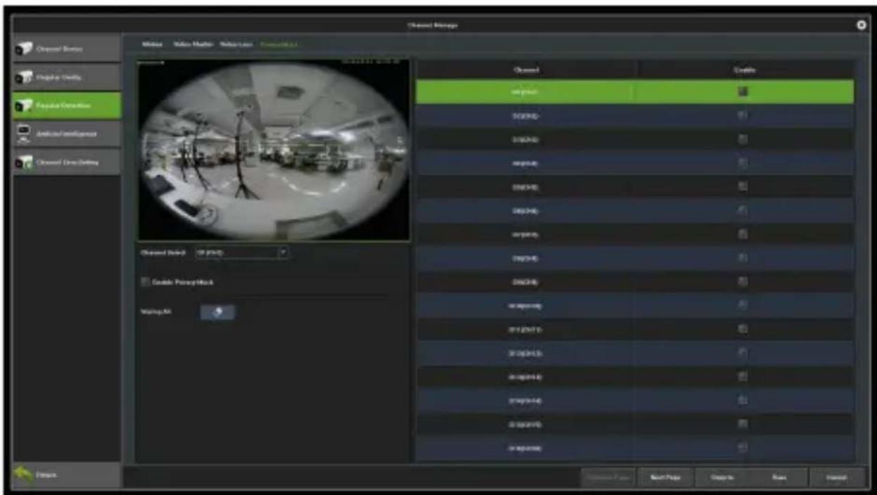
Figure 7.21 Video Mask
2) Select the camera to set the privacy mask.
3) Tick the check-box of Enable Privacy Mask to enable this feature.
4) Use the mouse to draw a zone on the window. You may configure up to 4 privacy mask zones and adjust the size of each area respectively.
5) You may click on the button to clear the configured privacy mask zones on the window.
6) Click on Save to save the settings.
Note: Onvif protocol does not support the privacy mask feature.
7.4 Intelligent Video Analysis
Intelligent Video Analysis is the vital function of NVR. This chapter will give you thorough and clear instructions in terms of the intelligent performance, operation process and parameter configuration.
7.4.1 Brief Introduction
Smart features of NVR include:
1) Behaviour analysis: target counting, object left/lost, intrusion detection, tripwire detection, scene changes.
2) Some of our NVRs are also equipped with features such as face detection, sound detection, fire detection, VQD, etc.
Note: Behaviour analysis supports both front-end and local detection modes, subject to the actual capacity of the product; while scene changing supports local detection mode only.
7.4.2 Enable Smart Analysis
Some NVR models disable local smart detection by default. To enable smart analysis, access the device parameters interface and set the preview capability to the mode with the smart analysis feature, as shown in Figure 7.22.
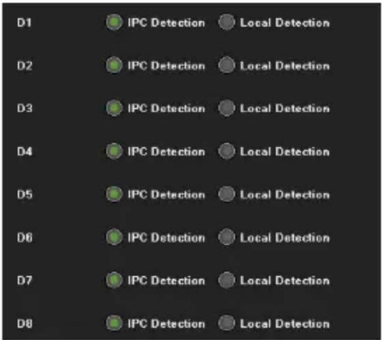
Figure 7.22 Model
Note: Currently the NVR's front-end smart function only supports ZKTECO protocol, so only when ZKTECO protocol accesses IPC can the IPC detection be turned on.
7.4.3 Function Configuration
Detect Mode
As shown in Figure 7.21, there are "IPC detection" and "local detection" modes; the former is the default setting. The IPC detection mode requires the IPC to support smart detection. If IPC front-end detection is not supported, the NVR Local Detection mode is then selected.
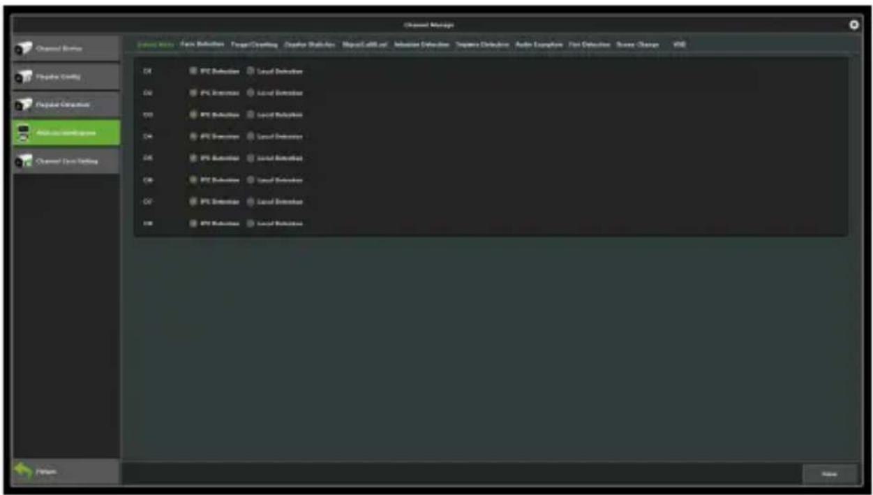
Figure 7.23 Detection Mode
Behaviour Analysis
Behaviour analysis includes the following functions: target counting, object left/lost, area detection, line crossing detection.
The target triggering rule is based on the centre of the target's lower edge (except height limit detection), which is generally the position of the human foot. So, when setting the detection line or detection area, the line/ area should not be suspended in the air.
The minimum height of the target should not be less than 1/32
of the image height; the minimum width should not be less than 1/64 of the image width; the maximum width of the proposed object should not exceed 1/4 of the image width; the maximum height should not exceed 1/2 of the image height.
Set the detection line or the detection area, but not too close to the target location. It also requires that the scope of view of the camera cannot be too small and the target cannot be too large.
Precautions:
1) Camera installation: install the device vertically to maintain static, avoid occlusion of vision, and make height appropriate (higher than two meters).
2) Scene selection: ensure adequate lighting, reduce the complexity of the site, try to avoid areas that may affect accuracy of detection, such as detection areas where there are leaves vibration, severe shadows, birds, insects and more; also, try to avoid reflective objects and scenes with glass, floor tiles, lakes and so on;
3) Alert area requirements: the warning area for intelligent analysis requires more than 1/8 of the area of the video
screen; if it is a cordon, the distance between the lines should exceed the image width or 1/4 of the height.
- Target counting
The purpose of this page is to configure relevant parameters so that the target count alarm occurs when a moving object whose area or volume is larger than a pre-defined value strides across the set detection line to obtain the number set by the detection rules, as shown in Figure 7.21. The following describes the parameters of the pages on the set method.
The purpose of this page is to configure relevant parameters so that the target count alarm occurs when a moving object whose area or volume is larger than a pre-defined value strides across the set detection line to obtain the number set by the detection rules, as shown in Figure 7.24. The following describes the parameters of the pages on the set method.
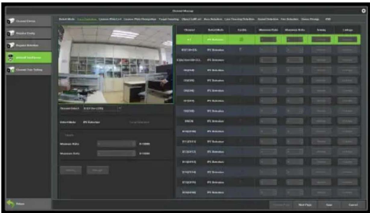
Figure 7.24 Target Counting
Channel Select: Select a channel.
Detect Mode: There are two modes: front-end and local. The two models to the actual capacity of the product subject. The front-end mode requires front-end access to IPC support; while the local model requires specific equipment.
Enable: Enable or disable the target count function.
Show in Preview: When enabled, you may see the detection line and the statistical results on the preview interface.
Detection line: Each screen supports up to four detection lines. Left-click and drag the mouse directly on the screen to draw the line, then release the left button and right-click to
complete the setting. Area between the detection lines are AB Area. The statistical results will be displayed on the upper side.
A → B: Acquiesce is area A to area B to increase counting, area A/ B location on both sides of detection line can be exchanged.
B → A: "Increment Count" or "Flow Count Results = 'A->Count of B' + 'B->Count of A'; "Count Down" > Count of B '-' B->Count of A"; 'Ignore' or 'Count of flow statistics' ='.
Ratio: Only when the size of a moving object on the screen is larger than the set size will be considered as a "target". A yellow dotted rectangle will appear as a reference when setting the centre of the view on the screen.
Traffic Statistics: Enable statistics and set the "Traffic Statistics Interval and Alarm Threshold".
Total Statistics: After the initial settings, you can set the "statistical time and total alarm threshold".
Arming: Set the deployment time. The default setting is all-day deployment.
Linkage: You can enter the linkage configuration page when the alarm is triggered and perform relevant linkage configuration operations.
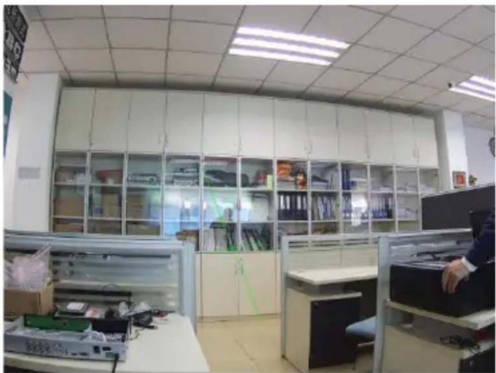
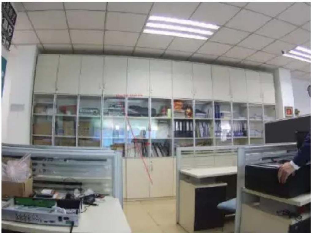
Delete: Click to clear the screen to set the history setting line. In accordance with the above settings, every 30s account for 150 times the number of objects through the detection line 1, trigger the alarm, as shown in Figure 7.25 and 7.26 is the pre-alarm and alarm occurs when the real-time preview screen.
natural_image
Interior view of a modern office or lab space with glass partitions, cubicles, and equipment (no visible text or symbols)Figure 7.25 Pre-alarm
natural_image
Interior view of a modern office or library with glass display cabinets and cubicles (no visible text or signage)Figure 7.26 Alarming
- Object Left/Lost
The purpose of this page is to configure the relevant parameters, so that more than the proportion of objects in the set detection area lost/ left over time detection time that goods detection alarm. The main parameters on the page set method are as shown in Figure 7.27.
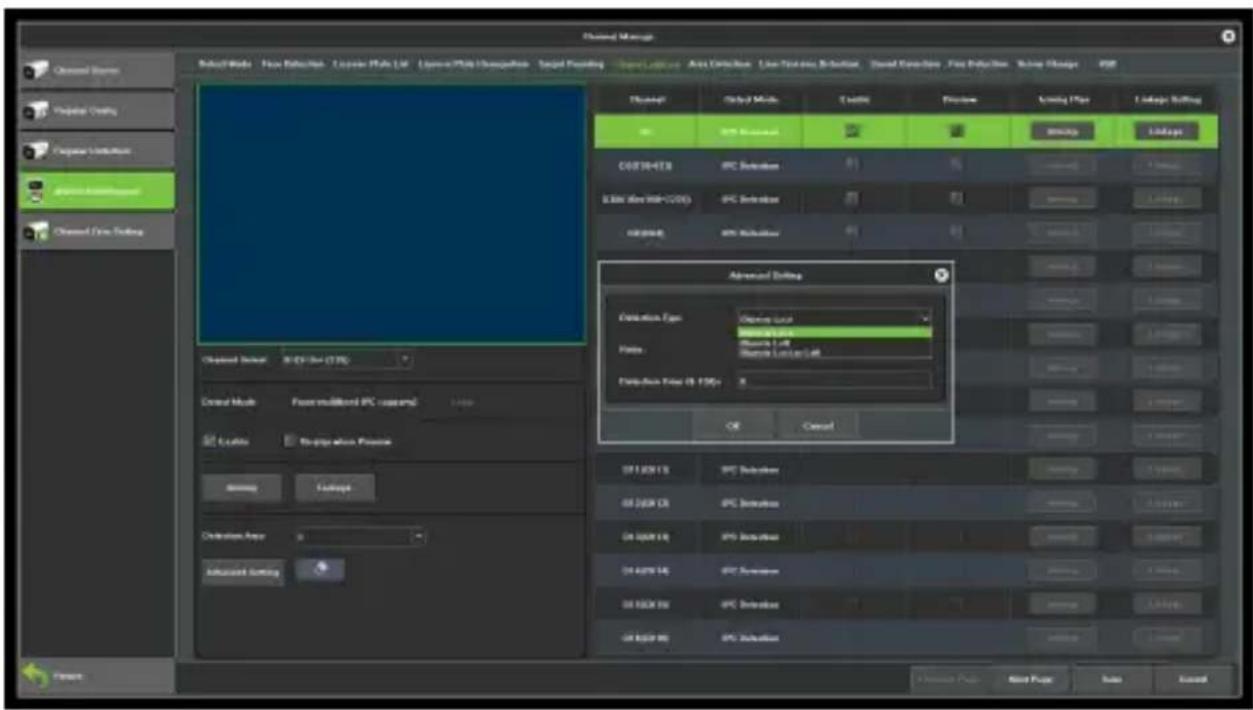
Figure 7.27 Goods Detection
Channel Select: Select a channel.
Detect Mode: There are two modes: front-end and local. These two modes to the actual capacity of the product subject. The front-end mode requires front-end access to IPC support; while the local model requires specific equipment.
Enable: Check to enable the target count.
Display when Preview: When this feature is enabled, you can see the detection line and the statistical results on the preview interface.
Detection Area: You may set up a maximum of 4 detection areas on each screen. Left-click and drag the mouse directly on
the screen to draw a line; after that, release the left button, move the cursor to the desired location, left-click and drag the mouse again to form another line, then right-click after the automatic closure of the formation of the region to complete forming the detection area (i.e. setting up a valid detection area by manually draw at least two lines).
Detection Type: "objects loss", "objects left", "objects loss or left".
Ratio: Moving objects in the screen than the size of the set when the size can be used as "items".
Detect Time: When the number of detected lost/ left items exceeds this set value, the system will trigger an alarm.
In accordance with the above settings, in the channel screen, the proportion of more than 150 items in the detection area disappeared more than 30s, triggered object left/lost alarm, alarm before and after the real-time preview screen, respectively, as shown in Figure 7.28 and Figure 7.29. (Which identifies the blue rectangle that is missing the area where the goods)
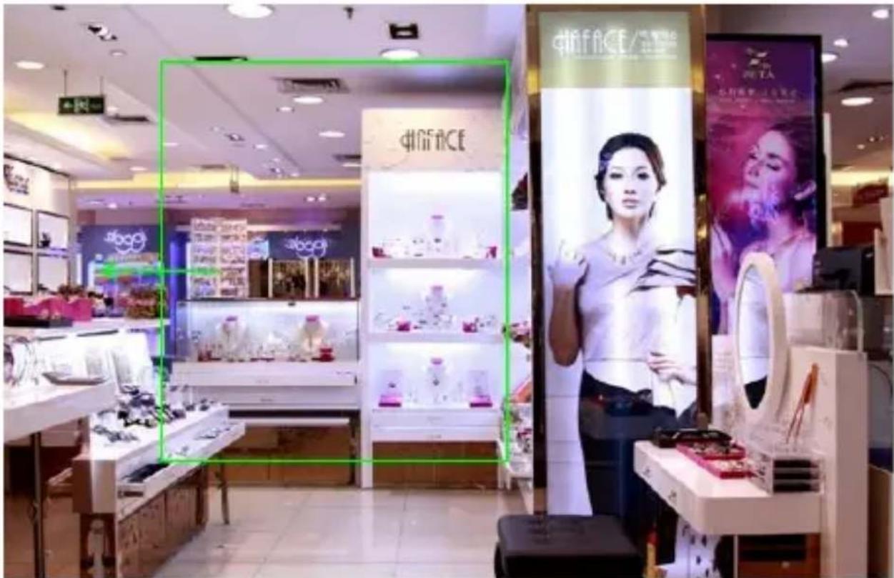
Figure 7.28 Pre-alarm
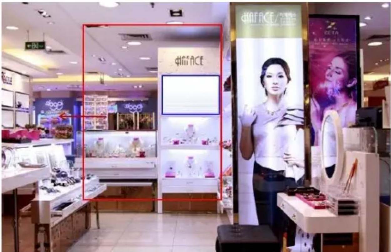
Figure 7.29 Alarming
- Area Detection
The purpose of this page is to configure the relevant parameters, so that more than the proportion of moving objects, enter / leave / hovering in the set detection area, over time detection zone detection alarm occurs. The interface as shown in Figure 7.30 describes the main parameters of the setting method.
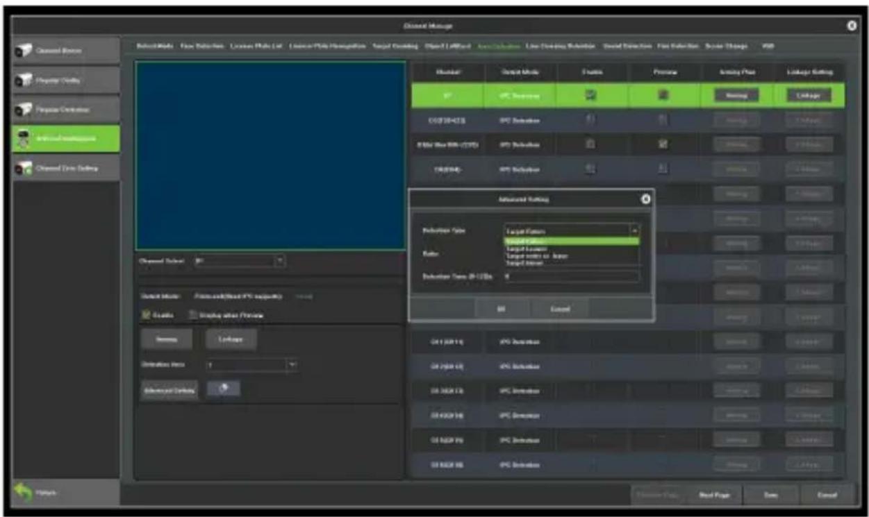
Figure 7.30 Area Detection
Channel: Select a channel.
Detect Mode: There are two modes: front-end and local. These two models to the actual capacity of the product subject. The front-end mode requires front-end access to IPC support; while
the local model requires specific equipment.
Enable: Set whether to enable the zone detection feature.
Show In Preview: Set whether to display the set rules and test results on the preview interface.
Detection area: the screen with the mouse to draw the area.
Detection type: "target to enter", "target to leave", "target to enter or leave", or "target wandering".
Ratio: The system will only consider a moving object captured by the camera shown on the screen as a "target" when its size or area is larger than the set value, a ratio of the size of the moving object to that of the detection area, which is measured in %.
Detect Time: When the number of target activity detected is more than this set value, the system will trigger an alarm.
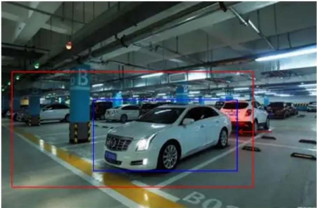
For your reference, when you set the value of the ratio to 1000, once there is a moving object (e.g. a vehicle) of which the size is over 1000 ‰ of the detection area enters such area for more than 5 seconds, the system will trigger the alarm. Below is the preview interface of the real-time picture taken when the alarm is triggered; the blue rectangle identifies the target that enters the area.
natural_image
Interior view of a parking garage with several white cars and a blue bounding box highlighting the center (no visible text or symbols)Figure 7.31 Area Detection
- Line Crossing
The purpose of this page is to configure the relevant parameters, so that more than the proportion of moving objects, across the set of test lines, the virtual alarm immediately alarm line. Below describes the main parameters of the page setting method.
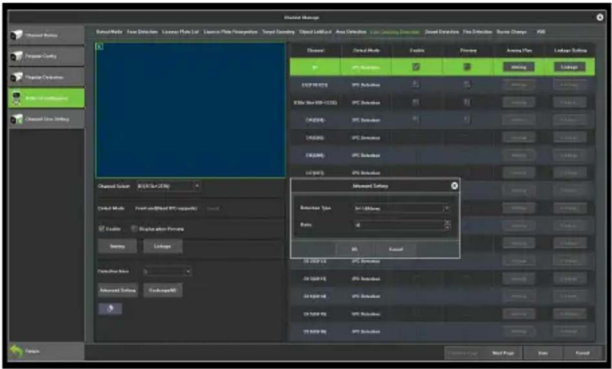
Figure 7.32 Line Crossing
Channel: Select a channel.
Detect Mode: There are two modes: front-end and local. These two models to the actual capacity of the product subject. The front-end mode requires front-end access to IPC support; while the local model requires specific equipment.
Enable: Set whether to enable the zone detection feature.
Show In Preview: Set whether to display the set rules and test results on the preview interface.
Detection Line: On the screen with the mouse to draw the test line, a key exchange A/B;
Detection Type: There are two types: "A-> B Alarm" and "A <->
B Alarm".
Area: Filter out less than the proportion of the set of moving objects.
According to the above settings, in this picture captured by a channel, accounted for more than 30 of the moving object, across the detection line from A region to B area, triggered area detection alarm, as shown in figure 7.33 is the alarm occurs real-time preview images (where the detection line or the red and green are blinking alternately, and the alarm is triggered, And the blue rectangle moves with the target crossing the cordon).
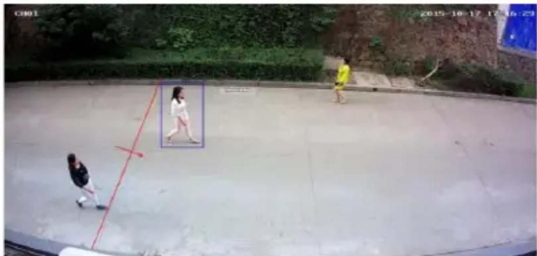
Figure 7.33 Line Crossing
- Scene Change
Figure 7.34 shows the situation where the front-end IPC
detects a change on the screen caused by manual or environmental factors, such as the camera being deflected, the camera being blocked, and the camera's angle or position being changed.
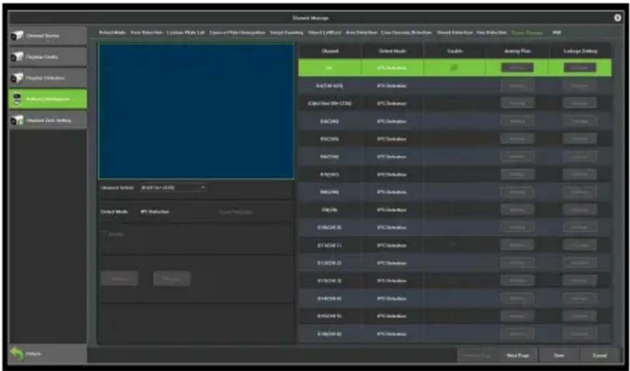
Figure 7.34 Scene Change
Channel: Select a channel.
Detect Mode: Only local detection mode is supported, and local device support is required.
Enable: Set whether to turn on scene change function.
7.5 Channel Zero Settings
7.5.1 Parameter configuration
The interface of parameter configuration is shown in Figure 7.33, then set the related channel information after enabling the parameter configuration.
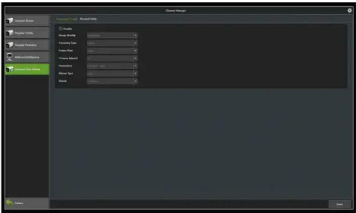
Figure 7.35 Parameter Configuration
Resolution: Set the video resolution.
Bitrate Type: Choose the bitrate type; the default setting is CBR.
Bitrate: Set the bitrate's upper limit.
Video frame rate: Set the frame rate according to specific requirements.
7.5.2 Channel Configuration
Below is the channel configuration interface.
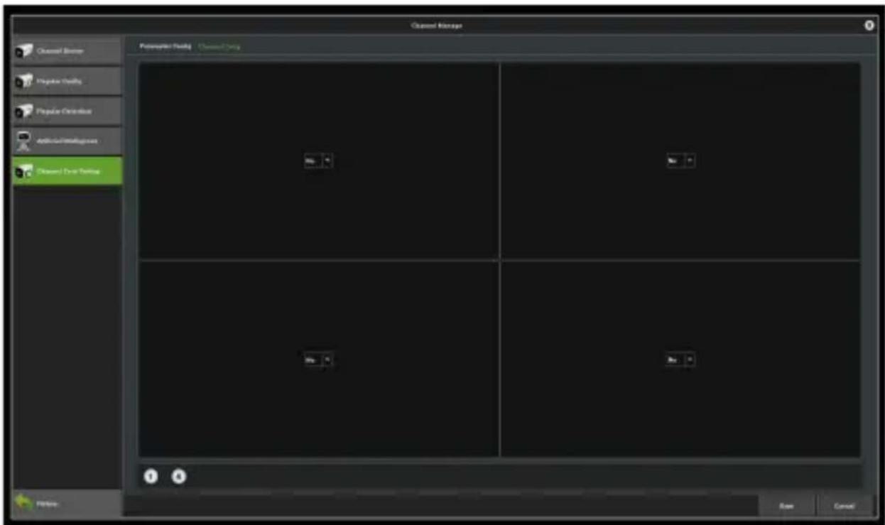
Figure 7.36 Channel Configuration
Chapter 8 Record Management
8.1 Record Configuration
Before starting:
Make sure that the HDD has already been installed. If not, please install an HDD.
Steps:
Enter the Record Configuration interface to configure the recording parameters, as shown in Figure 8.1.
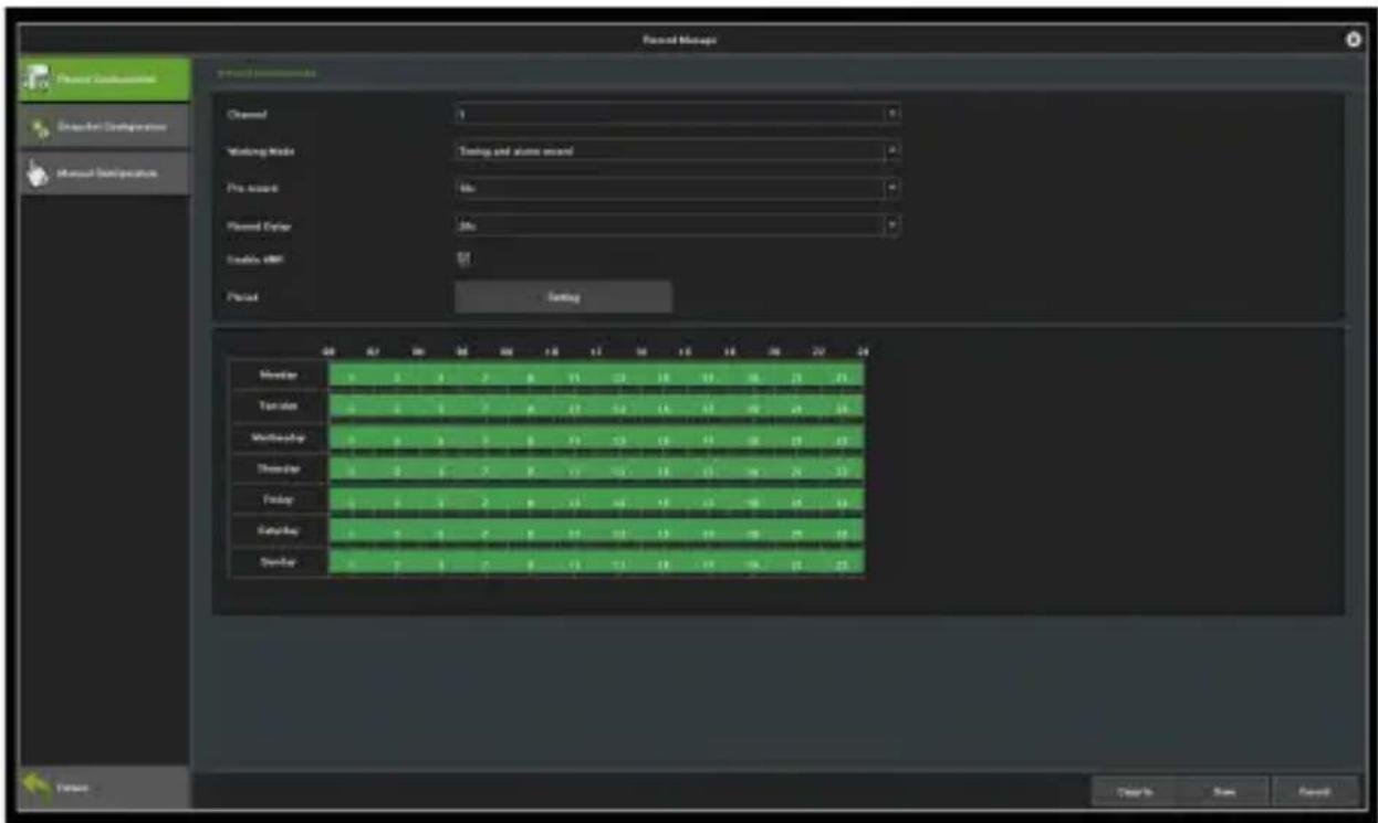
Figure 8.1 Interface of Record Settings
Select a channel you want to configure.
Select the record mode.
Click on the Setting button to set the record time, as shown in Figure 8.2.
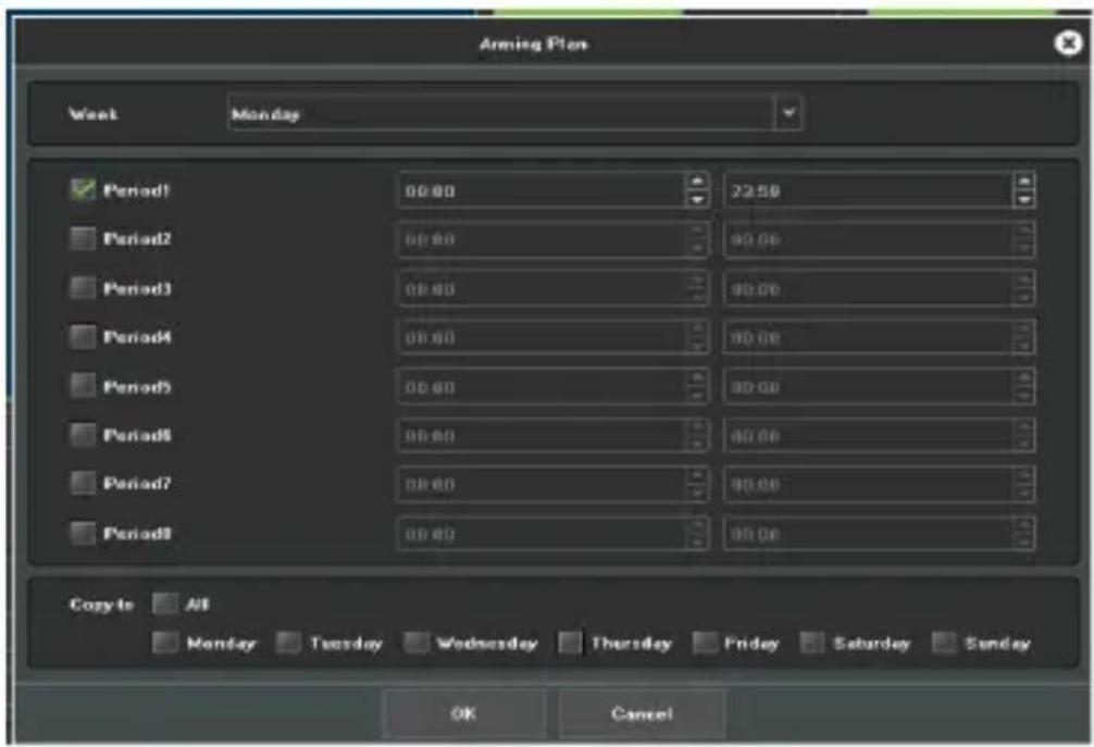
Figure 8.2 Arming Schedule
Pre-Record: The time you set to record before the scheduled time or event.
Record Delay: The time you set to record after the scheduled time or event.
Note: Use the "Copy to" button to duplicate the same settings to other channels as needed.
8.2 Manual Operations
8.2.1 Snapshots
Here is the snapshot interface.
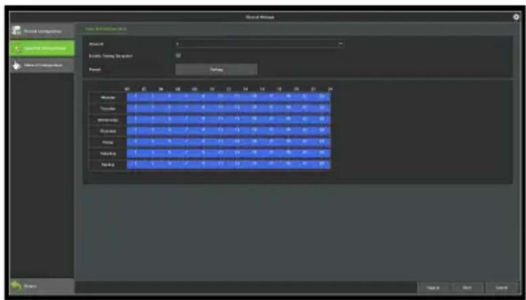
Figure 8.3 Snapshot
Chapter 9 Storage Management
Click on the 📄 icon to access the interface of disk backup. There are three modules on this interface. the following instructions, respectively.
9.1 Disk Information
Information on this page explains the detailed situation of the current NVR receive the hard disk, as shown in Figure 9.1. The device connects 1 hard disk and is in normal state video recording.
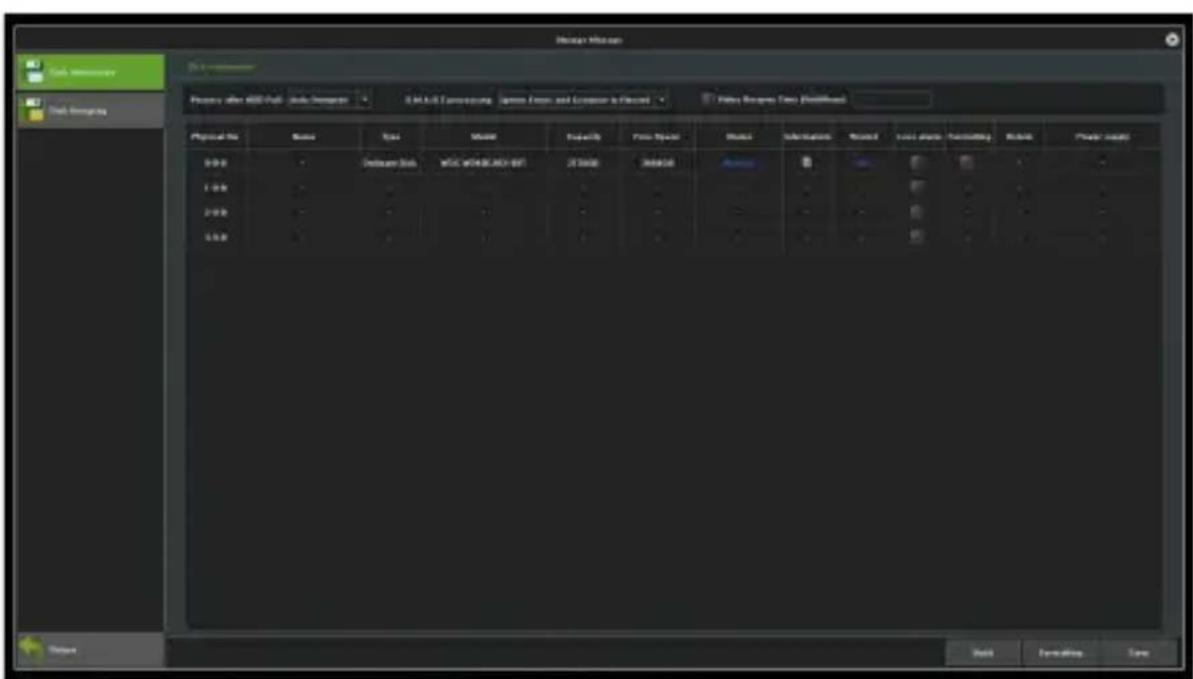
Figure 9.1 Disk Information
Process after HDD full: There are two ways: "Auto Overwrite" and "Stop Recording". The default setting is "Auto overwrite".
SMART processing: There are two ways: "Ignore error, continue recording" and "Error happen, stop recording".
SMART information: Click on the icon, then the system will pop up the SMART information list of the current hard disk.
Loss alarm: Detect that the SATA port will give an alarm if there is no hard disk connected;
Format: Check the hard disk which needs to be formatted,
then click on the formatting button. (Note: when the status is "Need to be formatted", only when the corresponding hard disk only when finish formatting corresponding hard disk, can the hard disk continue video, note: please don't do other operation in the process of formatting)
9.2 Disk Group
● Automatic Grouping
The system default is video in accordance with the "Automatic grouping", which means that videos recorded by all channels are defaulted to write video data on a hard disk, switch to next
hard disk after finish video, if the NVR connect only one hard disk, namely, in accordance with the type of storage management page in the "video post-processing" selected, cover the history video or stop video.
Please note that, when the number of channels of device video is more than 32 and connect multiple hard disk, to ensure the efficiency and performance of hard disk, default to video on two hard disks, video in one hard disk first 32CH of the video channel, the remaining channel video in another hard disk video.
- Manual Grouping
Manual grouping is to group channels together for better management. Channels from different groups can store videos on different hard disks. Each channel can be assigned quotas, as shown in Figure 9.2.
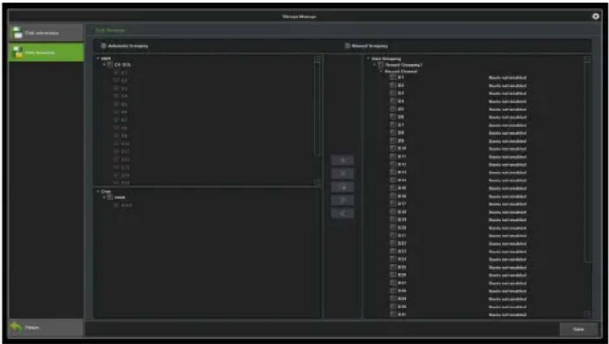
Figure 9.2 Manual Grouping
Above the middle column function button respectively are "Create a group", "delete the group", "quota setting", "Right move to add channels to group", "Left move to delete channels to group", note that, the channel preview without being added into the group won't video, the hard disk without being grouped is free hard disk, there would be no writing data.
Note: During manually grouping, the system may erase the old videos stored on the hard disk, please be careful when operating to avoid irreparable loss.
Chapter 10 System Management
Click on the icon to access the interface of system management. This sections includes four parts. For details, please see the below.
10.1 System Information
You may view the information of the device. Streaming information is available here.
10.1.1 Version Information
Below is the interface of device information, where you may view the versions of hardware and software.
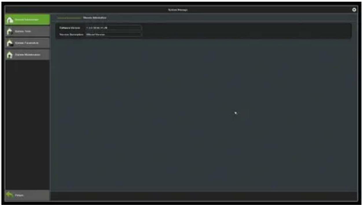
Figure 10.1 Version Information
10.1.2 Streaming Information
You may view the stream status of the current device here, as illustrated in Figure 10.2.
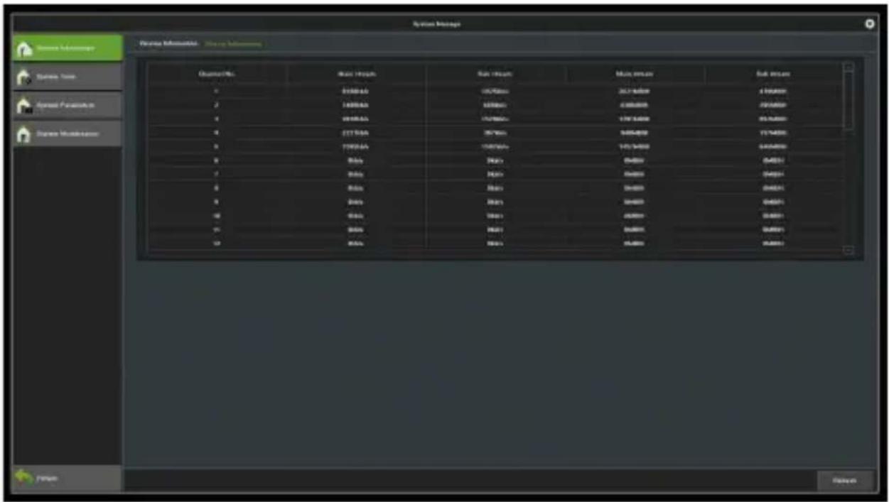
Figure 10.2 Stream Information
10.2 Time Settings
10.2.1 Device Time
Below is the time settings interface, where you may set the device's time and time zone.
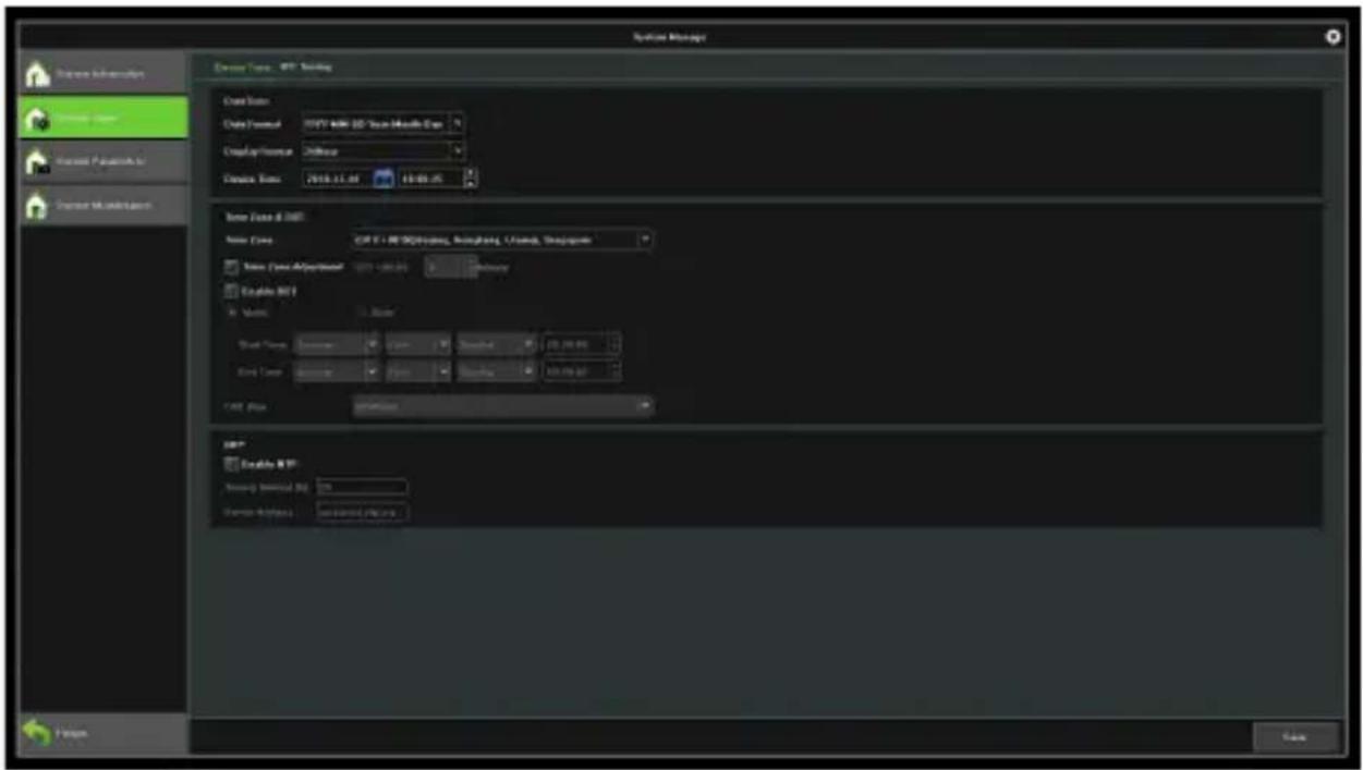
Figure 10.3 Time Settings
Data Format: Set the data format.
Device time: Manually modify the device time.
Time zone: Switch between time zones. When you tap on this button, the system will pop up a new date and time.
Enable DST: Click to enable daylight time. All you need to do is to set the starting and ending time.
NTP: Enable or disable the NTP. Before enabling, please make sure the device is connected to the network properly.
10.2.2 IPC Time
Below is the interface of IPC's time settings.
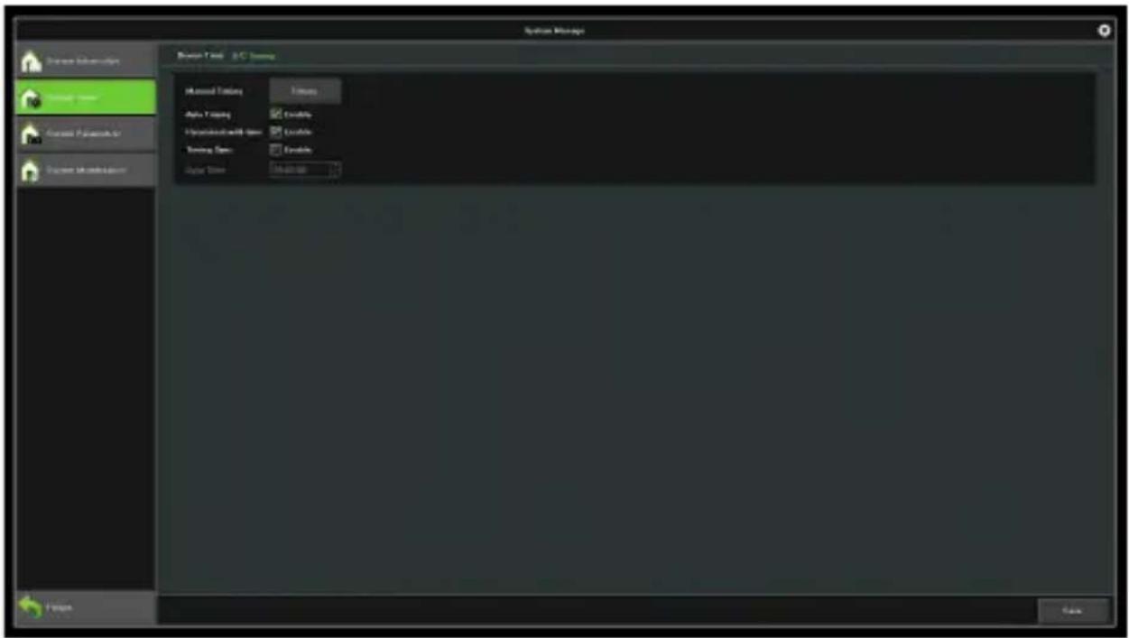
Figure 10.4 IPC Timing
Manual Timing: Click on this button to adjust the time of the IP camera as the device's time.
Auto Timing: When the auto-timing feature is enabled, time of the IP camera will not be the same as the device's time.
Reconnect with Time: When this feature is adopted, the time of the IP camera will synchronize with that of the device it is connected to.
Timing Sync: When this feature is adopted, the clock of the IP camera will synchronize with the time server of the NVR at the specified time per day.
10.3 System Parameters
Below is the interface of setting device parameters.
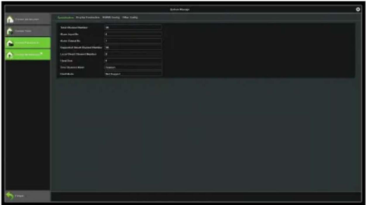
Figure 10.5 System Parameters
10.3.1 Display Parameters
Below is the interface of display settings.
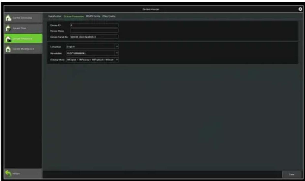
Figure 10.6 Display Parameters
Device ID: Click on this area to change the device ID.
Device Name: Click on this area to change the device name.
Language: Click on this button to change the language. The device will reboot after you change the language.
Resolution: Click on this button to select the desired resolution.
10.3.2 Other Configuration
Below is the interface of setting other configuration.
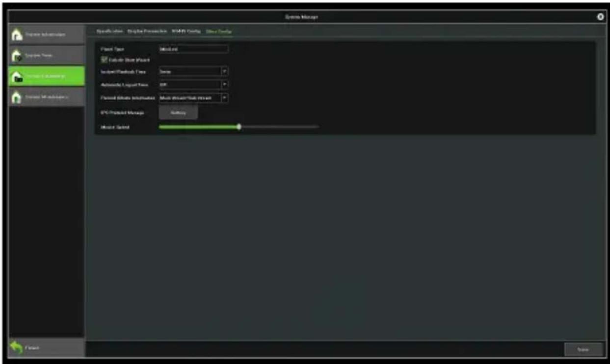
Figure 10.7 Other Configuration
Enable Start Wizard: Click on this button to adjust the start wizard.
Instant Playback Time: Click on this button to select the time of instant playback. You can change it from 5 minutes to 30 minutes.
Automatic Logout Time: Click on this button to select the time duration of remaining inactive before automatic logout. The device will not automatically log out when you change this feature to Off.
Record bitrate information: Click on this button to select the record bitrate.
IPC Protocol Management: Click on this button to select the IPC protocol, as shown in Figure 10.8.
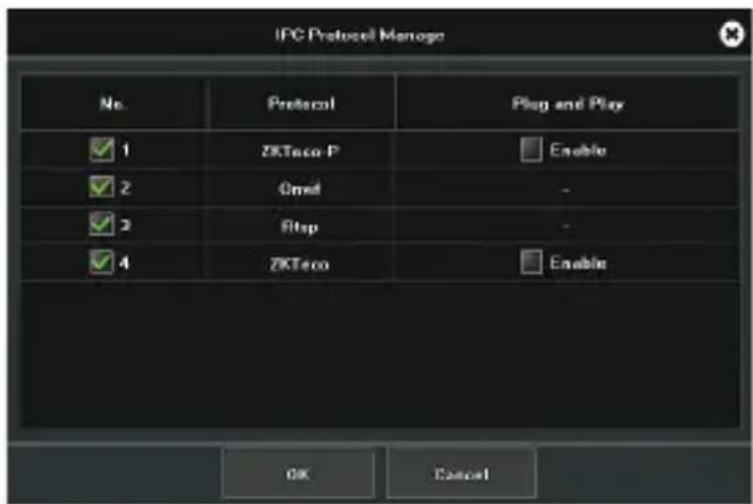
Figure 10.8 IPC Protocol Management
Mouse Speed: Move this button to adjust the cursor speed.
10.4 System Maintenance
10.4.1 Auto Maintenance
You may set the maintenance mode on this interface as shown in Figure 10.8. The default setting is "Disable". You may change it to once/ every day/ every week.
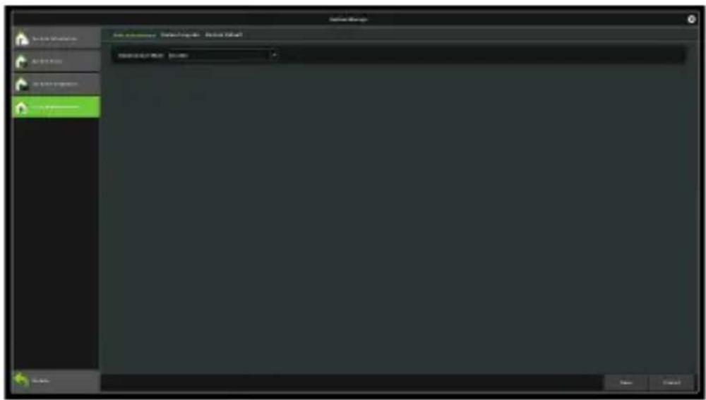
Figure 10.9 Auto Maintenance
10.4.2 System Upgrade
You can upgrade the device on this interface, as shown in Figure 10.10.
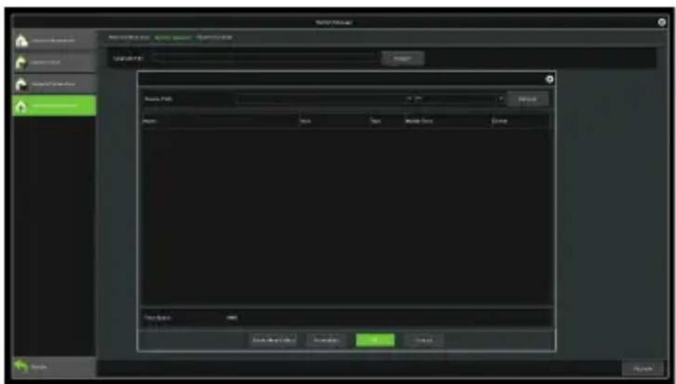
Figure 10.10 System Upgrade
10.4.3 Configuration Restoring
Below is the interface of configuration restoring.
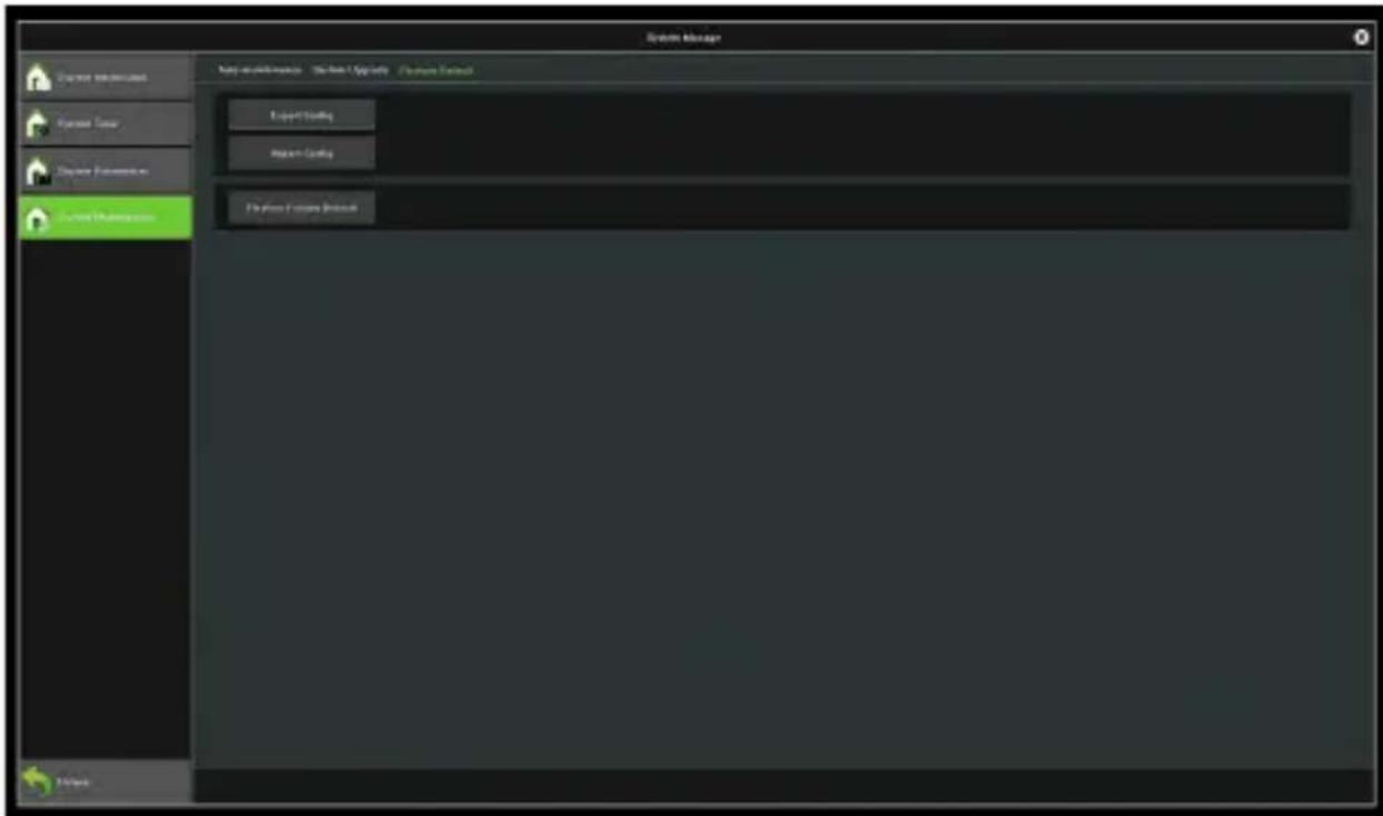
Figure 10.11 Configuration Restoring
Export config: Click on this button to export system config information.
Import config: Click on this button to import system config information.
Restore Factory Default: Click on this button to restore the device to factory settings.
Capture 11 Network Management
The module has 5 pages, the following description respectively.
11.1 Basic Settings
Below is the interface of network settings. You may set the IP parameters here, as shown in Figure 11.1.
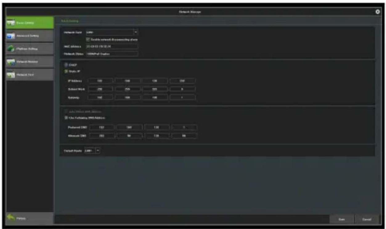
Figure 11.1 Basic Settings
Network card: You may choose a card type as needed.
MAC Address: View the physical address of the current
network interface; the address is not editable.
DHCP: When this feature is enabled, IP/mask/the gateway cannot be set. If the current DHCP is effective, then it will obtain a new IP/mask/gateway the router assigned (remote login is required to use the new IP address). If the change is not effective, the system will show the original address of the IP/mask/gateway. You may use the original IP address to remotely log in to the device.
IP: Set the IP address. The default IP of the network card 1 is 192.168.1.88.
Subnet Mask: Set the subnet mask.
Gateway: Set the gateway address.
11.2 Advanced Settings
Below is the interface of advanced settings.
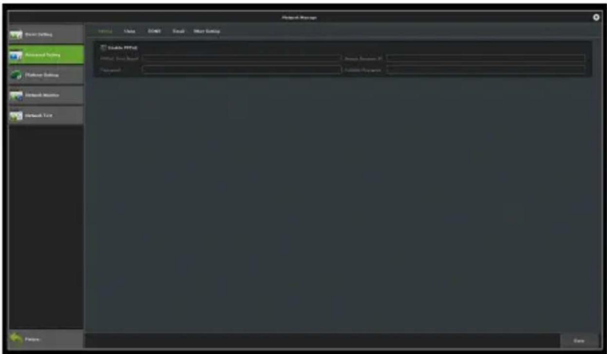
Figure 11.2 Advanced Settings
11.2.1 Enable PPPoE
You need to fill in the correct user name and password to use PPPoE. If the network is connected, the dynamic address of the device can be obtained.
11.2.2 Enable UPnP
The defaulted port numbers of RTSP, RTMP, HTTP, HTTPS and ONVIF are 554, 1935, 80, 8081 and 8082, respectively. The port numbers can be modified. After modification, the internal port need to restart the device to make the changes effective. The UPnP status is ineffective by default. The system will obtain the external IP address after the new UPNP setting.
11.2.3 DDNS Settings
The status is "Disable DNS" by default. Each set column cannot be set before switching the setting to "Enable DNS" status, as shown in Figure 11.3. Please ensure that the device is properly connected to the network before operation.
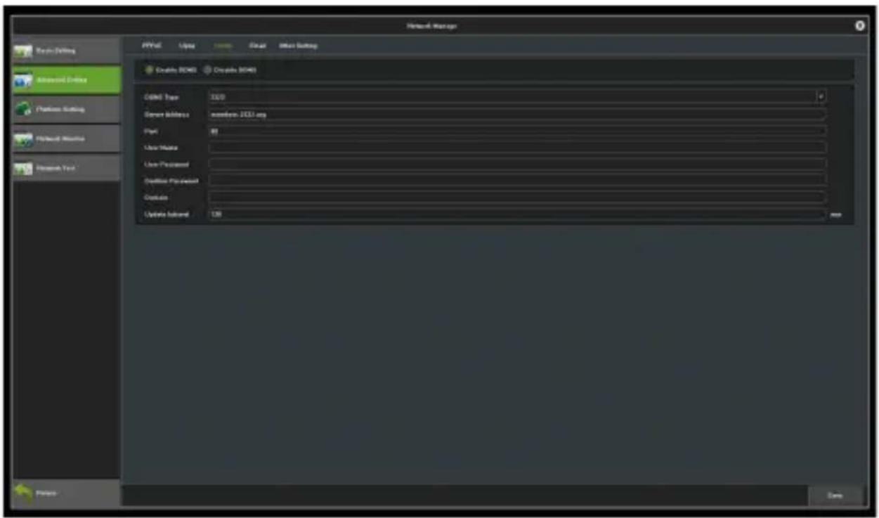
Figure 11.3 DDNS Settings
DDNS Type: 5 types available.
Server Address: Each type of server corresponds to the domain name of the existing default server.
Port: Each type of server corresponds to the existing default port.
The User Name and Password: Manually enter the correct user name and password.
Domain: Manually enter the correct domain name. After the function is OK, you may use the domain name remote access device.
Update Interval: Update the interval time.
11.2.4 Email Settings
Settings on this interface is used with "Email Linkage" in "Linkage Setting". You need to input the sender's email address and password, the recipient's email address, the address of the SMTP server and information of the port information in the corresponding fields according to the requirements for the format. Here are other additional features on the page, as shown in figure 11.4.
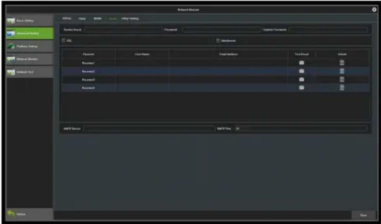
Figure 11.4 Email Settings
1) Fill in the multiple recipient mailbox. The sender's email address will send E-mail to multiple recipients' mailbox at
the same time.
2) Tap the Attachment checkbox. The mail the recipient received in his mailbox is with attachments. The attachment is a linkage capture file, in zip format, of the corresponding channel.
3) Click on the icon corresponds to the "Test mail" field. Let the sender's mailbox send a mail to the recipient's mailbox. Whether the mail is sent successfully or not, the system will show you a prompt.
Notice: use the e-mail linkage function to ensure good networking and smooth access to the external network.
11.3 Management Platform
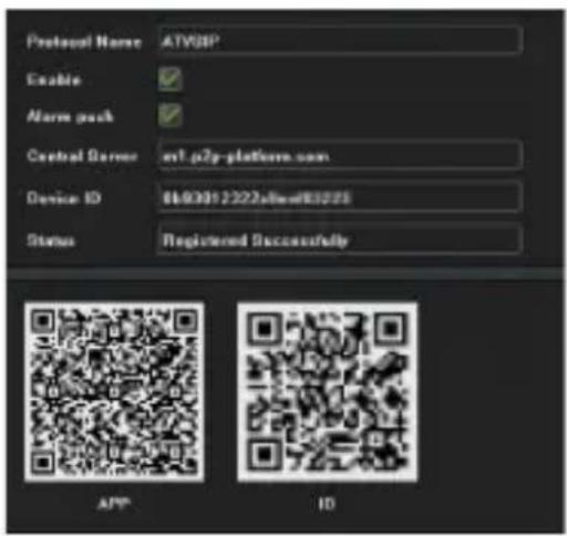
This page is the enable interface of the platform agreement, as shown in Figure 11.5. The default setting is enabling the Web Server protocols, which support remote login. You may enable other protocols as needed. Please note that the changes will only be effective after the device is restarted.
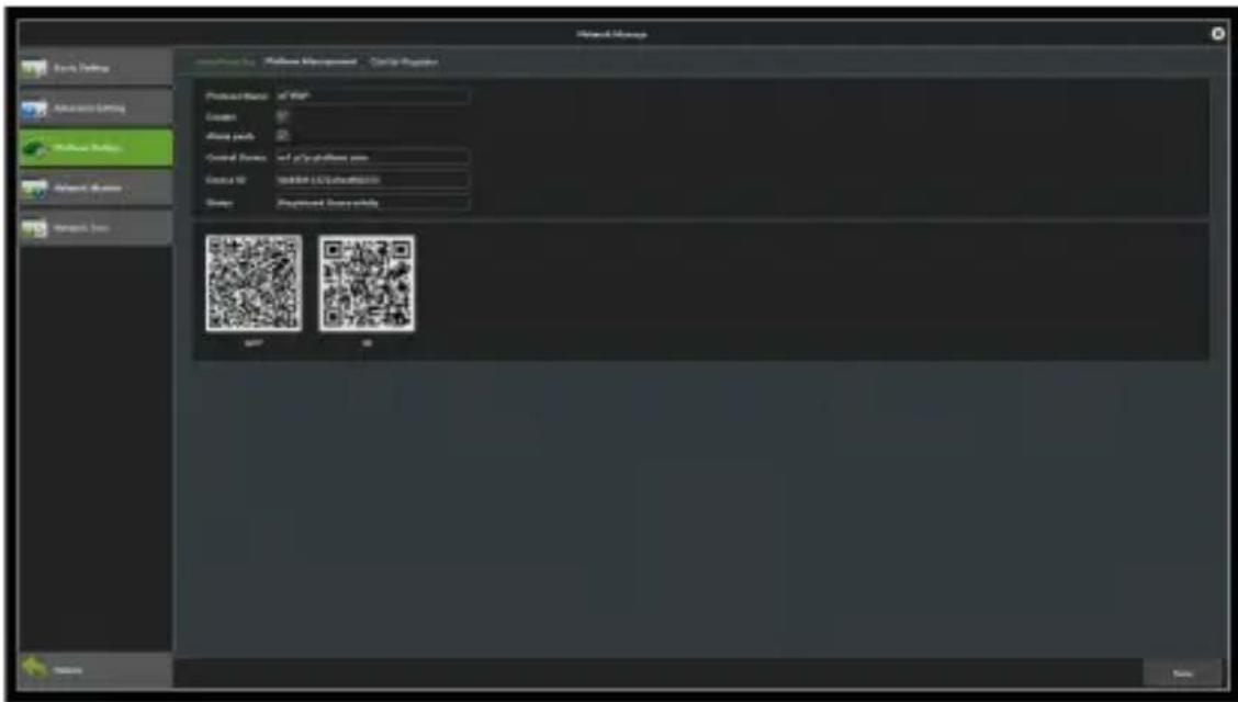
Figure 11.5 Management platform
Click on the AntarView Pro icon to view the AntarView Pro QR code, as shown in the figure below.
11.4 Network Flow
As shown in Figure 11.6, you may monitor the network traffic of the current device in this module.
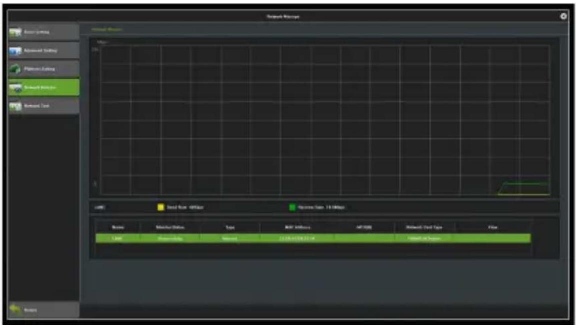
Figure 11.6 Network Flow
11.5 Network Test
Below is the interface of network test.
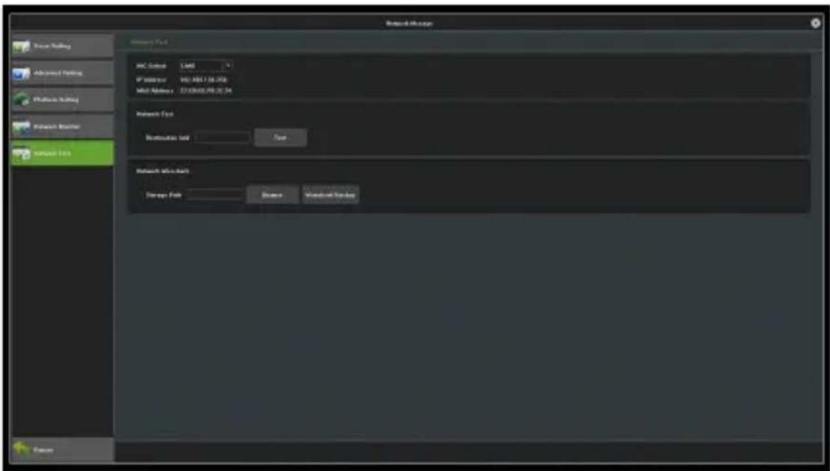
Figure 11.7 Network Test
NIC Select: Select a network card; the default setting is network card 1.
Destination Add: Input the network address of the network that needs to be tested.
Network Wireshark: Click on browse, set up the storage path, click on Wireshark backup, then complete backup.
Capture 12 Alarm Management
This module consists of 3 interfaces. Below is the description of each one.

Figure 12.1 Alarm Management Interface
12.1 Abnormal Events
You can change the type of abnormal events alarm on this interface, as shown in Figure 12.2.
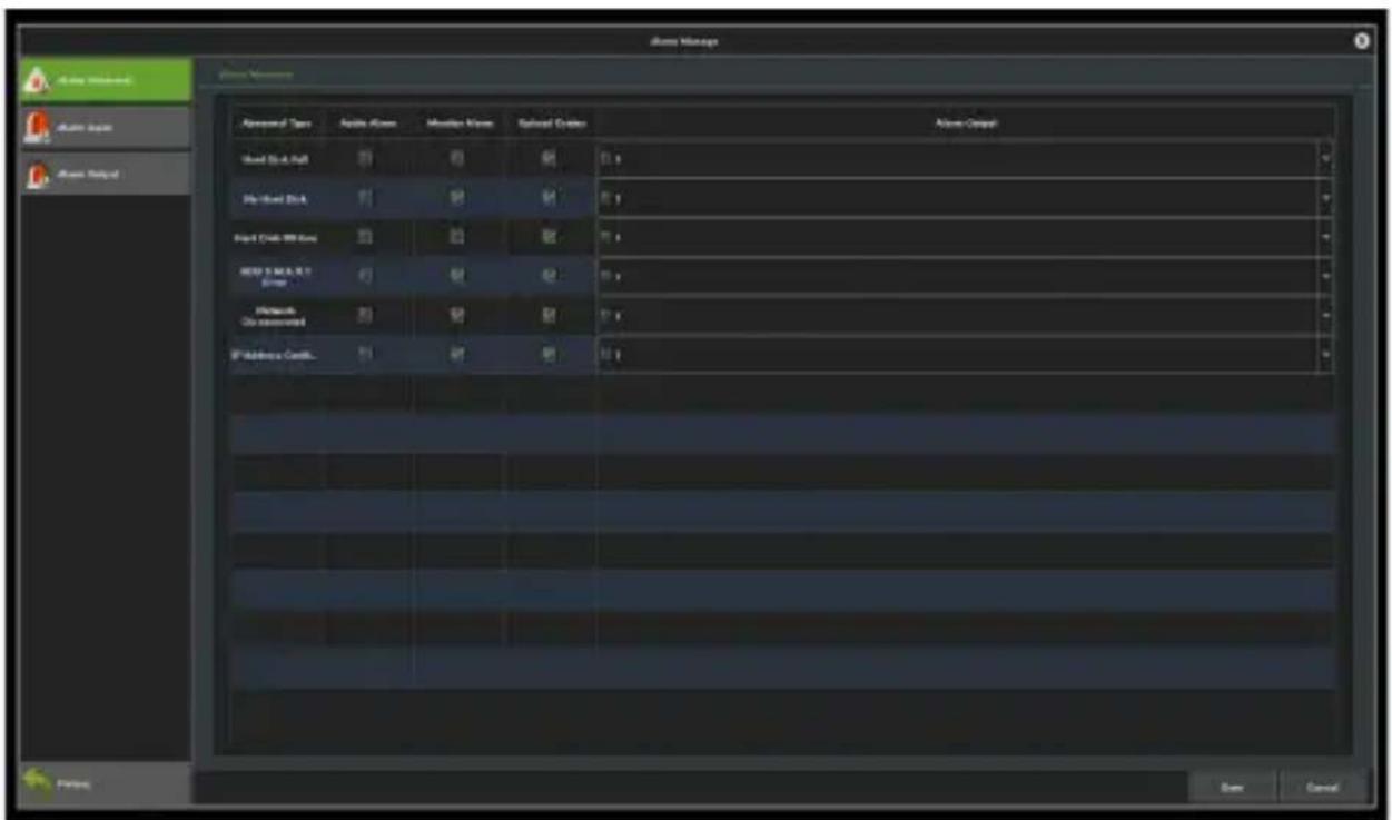
Figure 12.2 Abnormal Events
Audio Alarm: The buzzer will be triggered when it receives an alarm signal.
Monitor Alarm: Show the alarm information on the preview interface.
Upload Center: Upload a warning message to the network center when an alarm is triggered.
Alarm Output: Relay or warning outputs will operate when certain conditions occur.
12.2 Alarm Input
Below is the interface of alarm input.
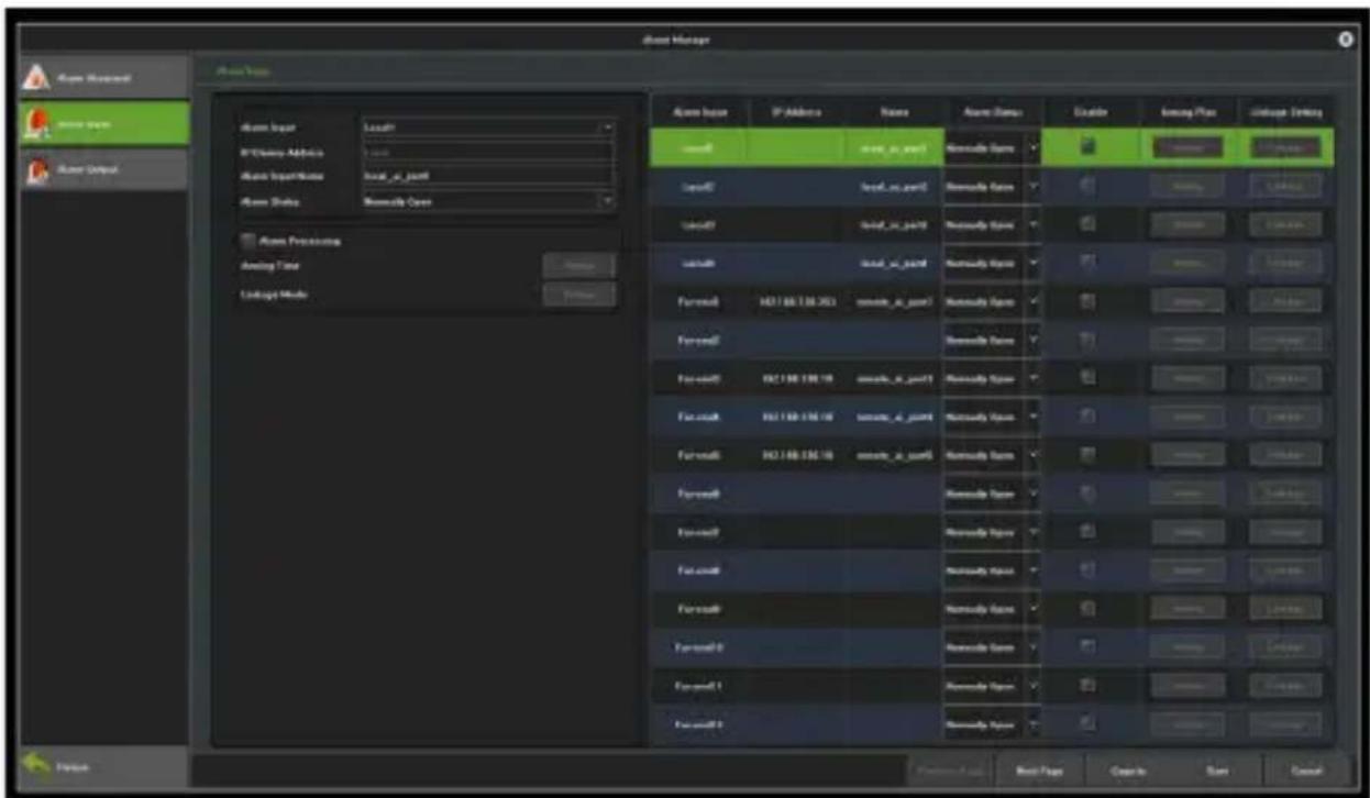
Figure 12.3 Alarm Input
Alarm Input: Select an alarm channel.
Alarm Input Name: Edit the name of an alarm.
Alarm Status: Set the alarm state. The default setting is "always open".
Arming Time: Set the arming schedule, as shown in Figure 12.4.
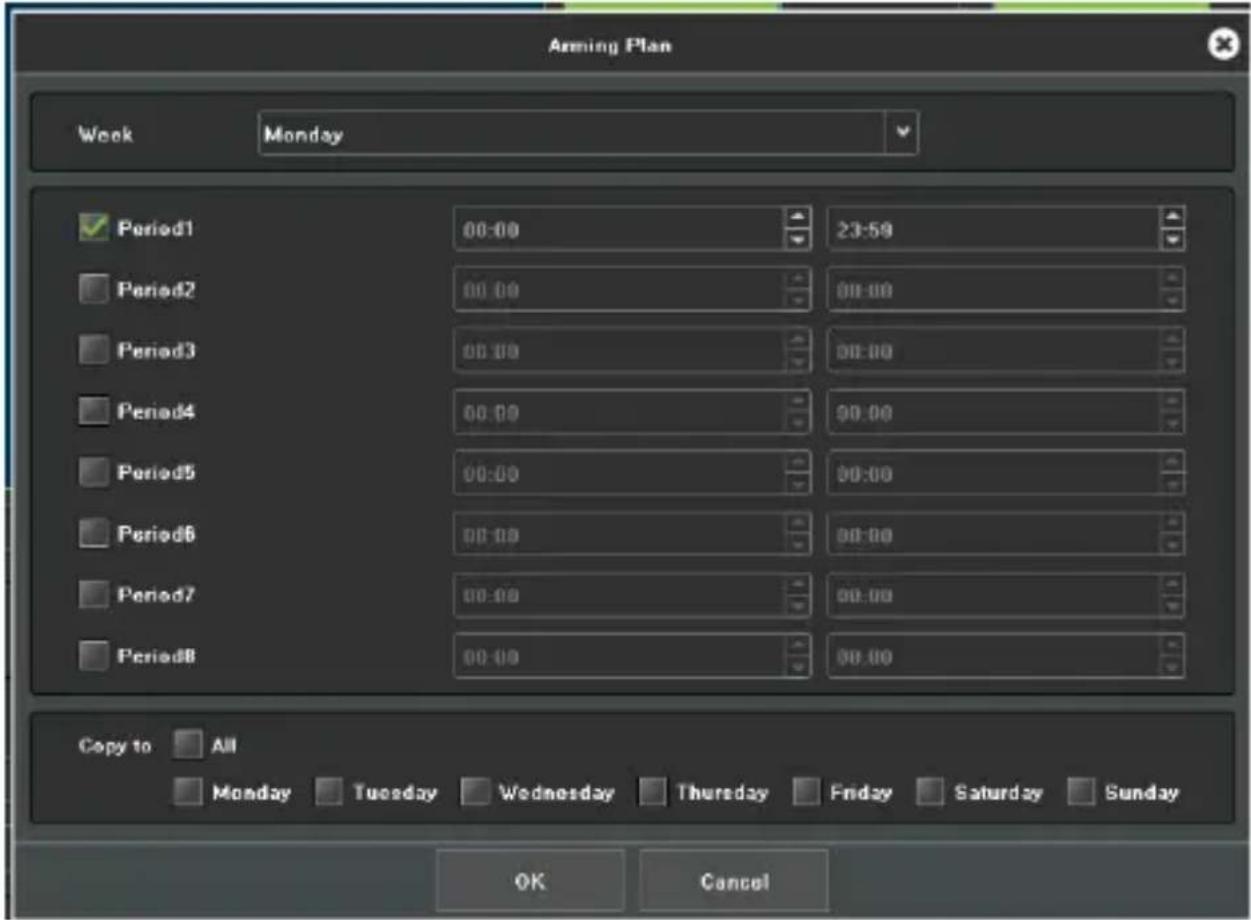
Figure 12.4 Arming Plan
Linkage Mode: Choose the type of alarm linkage, as shown in Figure 12.5.
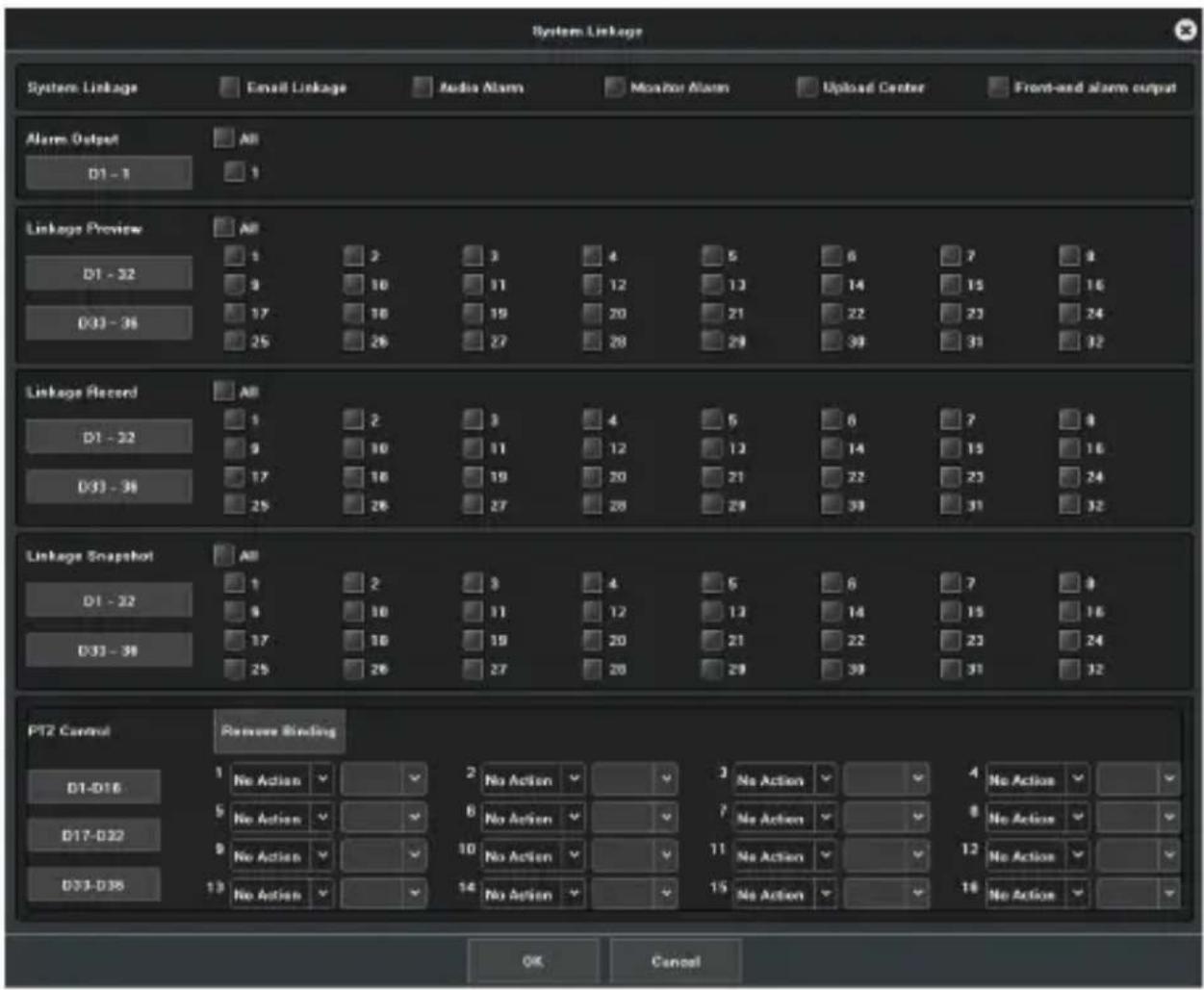
Figure 12.5 Linkage mode
12.3 Alarm Output
Below is the interface of alarm output settings.
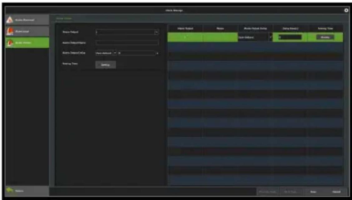
Figure 12.6 Alarm Output
Alarm Output: Select an alarm output.
Alarm Output Delay: Set the alarm delay time.
Arming Time: Set the schedule that needs arming, as shown in Figure 12.7.
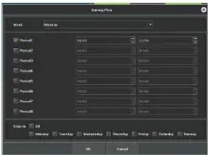
Figure 12.7 Arming Plan
Capture 13 User Management
The user management interface is shown in Figure 13.1. You may modify the user information and user permissions here.
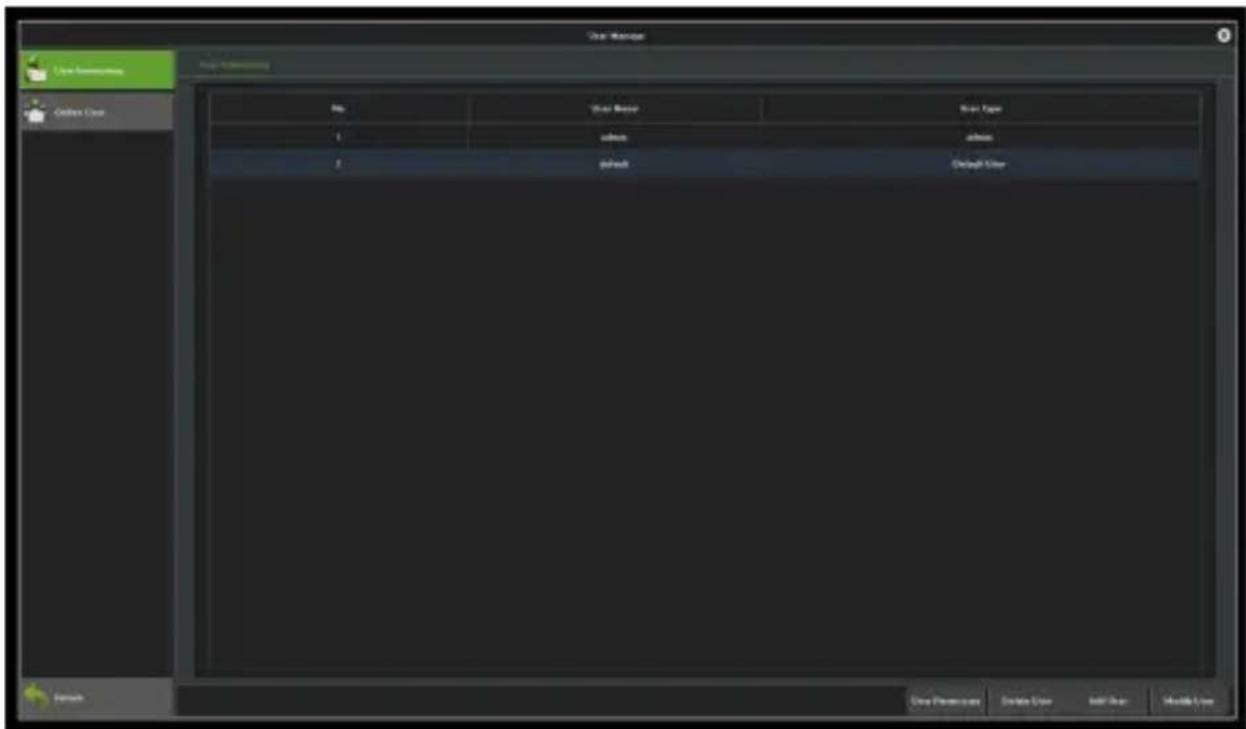
Figure 13.1 User Management
Modify User: Modify the selected user password, as shown in Figure 13.2.
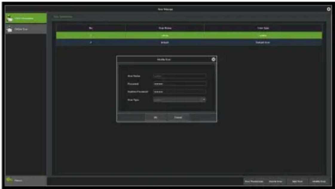
Figure 13.2 Modify users
Add User: Add a new user, as shown in Figure 13.3, then fill in the user name, password and select User Type.
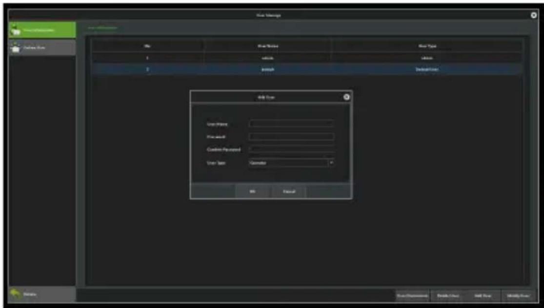
Figure 13.3 Add User
Delete users: You may delete the selected users, except the admin and default users.
User Permission: Set the permissions for selected users, as shown in Figure 13.4.
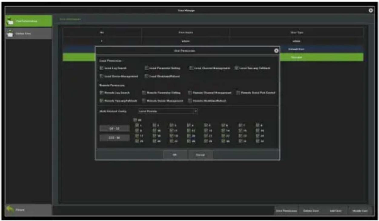
Figure 13.4 User Permission
Appendix
List of compatible HDD already tested
| Manufacturer | Capacity Model |
| TOSHIBA | 1.0TB DT01ABA100VOCT-2015 |
| 1.0TB DT01ABA100VMAY-2015 | |
| 2.0TB DT01ABA200VFEB-2015 | |
| Seagate | 1.0TB ST1000VM002 |
| 1.0TB ST1000DM003 | |
| 2.0TB ST2000VX000 | |
| WD | 500GB WD5000AVDS-63U7B1 |
| 2.0TB WD20PURX-64P6ZY0 | |
| 3.0TB WD30PURX-64P6ZY0 |

- Trademark
- About This Manual
- Disclaimer
- Contact
- Contents
- Chapter 1 Installation ....6
- Chapter 2 Getting Started....11
- Chapter 3 Preview....19
- Chapter 4 Playback.... 28
- Chapter 5 PTZ Controls....38
- Chapter 6 Search....43
- Chapter 7 Channel Management...... 47
- Chapter 8 Record Management 88
- Chapter 9 Storage Management.... 91
- Chapter 10 System Management 95
- Capture 11 Network Management....106
- Capture 12 Alarm Management....116
- Capture 13 User Management....122
- Appendix....125
- Chapter 1 Installation
- Unpacking
- Hard Disk Installation
- Before starting:
- NVR with 1 or 2 HDDs.
- Steps:
- NVR with 4 or 8 HDDs.
- Steps :
- Chapter 2 Getting Started
- Starting up and Shutting down
- Starting up
- Shutting down
- Logging in
- Using the Guide
- Operating the guide
- Menu operations
- Setup
- Chapter 3 Preview
- Introduction of Preview
- Channel preview icons
- PTZ/ Preset/ Cruise/ Pattern:
- Operations in Preview Mode
- 1) P2P information
- 4) System Sound
- 5) Other functions
- Using the Mouse in Preview
- Chapter 4 Playback
- Instant Playback
- Purpose:
- Playback by Normal Search
- Recording Playback
- Notes:
- Playback Interface
- Playback by Event Search
- Playback of Pictures
- Playback of External Files
- Playback Backup
- Backup button.
- Chapter 5 PTZ Controls
- Setting PTZ Preset, Cruise, Pattern & Linear Scan
- Preset Settings
- Cruise Settings
- 2) Click on the
- Pattern Settings
- Linear Scan Settings
- Chapter 6 Search
- Log Retrieval
- Image Retrieval
- Video Retrieval
- Chapter 7 Channel Management
- Adding IP Cameras
- Regular Configuration
- Channel Display
- Channel Management → Regular Configuration → Channel Display
- Media Parameters
- Snapshot Parameters
- PTZ Settings
- Tour Grouping
- Regular Detection
- Motion Detection
- Video Lost
- Video Tampering
- Privacy Mask
- Intelligent Video Analysis
- Brief Introduction
- Enable Smart Analysis
- Function Configuration
- Detect Mode
- Behaviour Analysis
- Precautions:
- - Target counting
- - Object Left/Lost
- - Area Detection
- - Line Crossing
- - Scene Change
- Channel Zero Settings
- Parameter configuration
- Channel Configuration
- Chapter 8 Record Management
- Record Configuration
- Manual Operations
- Snapshots
- Chapter 9 Storage Management
- Disk Information
- Disk Group
- ● Automatic Grouping
- - Manual Grouping
- Chapter 10 System Management
- System Information
- Version Information
- Streaming Information
- Time Settings
- Device Time
- IPC Time
- System Parameters
- Display Parameters
- Other Configuration
- System Maintenance
- Auto Maintenance
- System Upgrade
- Configuration Restoring
- Capture 11 Network Management
- Basic Settings
- Advanced Settings
- Enable PPPoE
- Enable UPnP
- DDNS Settings
- Email Settings
- Management Platform
- Network Flow
- Network Test
- Capture 12 Alarm Management
- Abnormal Events
- Alarm Input
- Alarm Output
- Capture 13 User Management
- Appendix
Brand : ZKTeco
Model : Z8564
Category : Security Camera