PL-52A12G - Security Camera ZKTeco - Free user manual and instructions
Find the device manual for free PL-52A12G ZKTeco in PDF.

User questions about PL-52A12G ZKTeco
0 question about this device. Answer the ones you know or ask your own.
Ask a new question about this device
Download the instructions for your Security Camera in PDF format for free! Find your manual PL-52A12G - ZKTeco and take your electronic device back in hand. On this page are published all the documents necessary for the use of your device. PL-52A12G by ZKTeco.
USER MANUAL PL-52A12G ZKTeco
WARNINGS AND CAUTIONS
WARNING
TO REDUCE THE RISK OF FIRE OR ELECTRIC SHOCK, DO NOT EXPOSE THIS PRODUCT TO RAIN OR MOISTURE. DO NOT INSERT ANY METALLIC OBJECTS THROUGH VENTILATION GRILLS OR OPENINGS ON THE EQUIPMENT.
CAUTION


EXPLANATION OF GRAPHICAL SYMBOLS

The lighting flash with arrowhead symbol, within an equilateral triangle, is intended to alert the user the presence of non-insulated "dangerous voltage" within the product's enclosure that maybe of sufficient magnitude to constitute a risk of electric shock to different persons.

The exclamation point within an equilateral triangle, is intended to alert the user the presence of important operating and maintenance (servicing) instructions in the literature accompanying this product
PRECAUTIONS:
- Persons without technical qualifications should not attempt to operate this dome device before reading this manual thoroughly.
- Remove any power to the dome before attempting any operations or adjustments inside the dome cover to avoid potential damage to the mechanism.
- Inside the dome cover there are precision optical and electrical devices. Heavy pressure, shock and other sudden adjustments or operations should be avoided. Otherwise, you may cause irreparable damage to the product.
- Please DO NOT remove or disassemble any internal parts of the video camera to avoid normal operation and possibly void the warranty. There are no serviceable parts inside the camera.
- All electrical connections to the dome should be made in strict accordance with the attached labels and wiring instructions in this manual. Failure to do so may damage the dome beyond repair and void the warranty.
- For outdoor installation especially in high places or poles, it is highly recommended that the proper lightning arrestors and surge suppressors are installed before the dome is entered into service.
- Please do not use the product under circumstances where the limits exceed the maximum specified temperature, humidity or power supply specifications.
- First please set the network data after login. The gateway address is the one to connect the IP camera.
- IP address should be different from other devices' IP address. Otherwise, video is not available.
IMPORTANT SAFEGUARDS
- Read these instructions before attempting installation or operation of dome device.
- Keep these instructions for future reference.
- Heed all warnings and adhere to electrical specifications follow all instructions.
- Clean only with non abrasive dry cotton cloth, lint free and approved acrylic cleaners.
- Should the lens of the camera become dirty, use special lens cleaning cloth and solution to properly clean it.
- Do not block any ventilation openings. Install in accordance with manufacturer's instructions.
- Use only attachments or accessories specified by the manufacturer.
- Verify that the surface you are planning to use for attaching the dome can adequately support the weight of the device and mounting hardware.
- Protect this device against lighting storms with proper power supplies.
- Refer all servicing to qualified service personnel. Servicing is required when the device has been damaged in any way, when liquid traces are present, or the presence of loose objects is evident or if the device does not function properly, or has received sever impact or has been dropped accidentally.
- Indoor dome is for indoor use only and not suitable for outdoor or high humidity locations. Do not use this product under circumstances exceeding specified temperature and humidity ratings.
- Avoid pointing the camera directly to the sun or other extremely bright objects for prolonged period of time avoiding the risk of permanent damages to the imaging sensor.
- The attached instructions are for use by qualified personnel only. To reduce the risks of electric shock do not perform any servicing other than contained in the operating instructions unless you are qualified to do so.
- During usage, user should abide by all electrical safety standards and adhere to electrical specifications for the operation of the dome.
- Use supplied power supply transformer only.
INDEX
WARNINGS AND CAUTIONS ....1
WARNING....1
CAUTION ....1
EXPLANATION OF GRAPHICAL SYMBOLS....1
PRECAUTIONS: 2
IMPORTANT SAFEGUARDS ....3
1 Product Introduction....1
1.1 Package Contents....1
1.2 Specification 2
1.3 Performance Features ....4
2 Installation....5
2.1 Dimension ....5
2.2 Installation....6
2.2.1 Wall Mounted....6
2.2.2 Corner Mounted....7
2.2.3 Pole Mounted....9
2.2.4 Ceiling Mounted ....10
2.3 Connection....12
2.3.1 PTZ Connection Way 12
2.3.2 Connecting the Device ....12
2.3.3 Setting the IE Browser....12
2.3.4 Install Video Software....13
2.4 Login IE Interface 15
2.5 Browser 17
2.5.1 Video Browsing....17
2.5.2 PTZ Control 17
2.5.3 PTZ Function....18
2.5.4 Common Shortcuts....19
2.6 Setting....20
2.6.1 System 20
2.6.2 Network....23
2.6.3 Management Software....28
2.6.4 IP Cameras....28
2.6.5 Audio & Video ....33
2.6.6 PTZ Function....37
2.6.7 Alarm 39
2.6.8 User....40
2.6.9 log....41
- Function Instruction....42
3.1 Basic Function 42
3.2 Special Function....43
Appendix I Anti-lightning, Anti-surge 44
Appendix II Clean Transparent Cover 45
Appendix III Exception Handling....46
Copyright Statement....47
* Indicates the functions with default protocol, it might not function by using other protocols
※ Indicates the optional functions, only with certain mode
1 Product Introduction
1.1 Package Contents
IP IR Speed dome 1pc
Wall mount bracket 1pc
Power supply 1pc
Screws kits 1pc
User manual 1pc
CD (with CMS etc.) 1pc
1.2 Specification
| Image Sensor | 1/3" SONY CMOS |
| Preview video resolution | 1920×1080 |
| Mini Illumination | Color:0.5Lux B/W:0.05Lux IR ON:0Lux |
| Signal Noise Ratio | ≥50dB |
| Focus Auto/Manual | |
| D/N IR-Cut | |
| F-Stop F1.6(color),F1.8(IR on),Auto | |
| Close-up INF(Color),1000mm(Far) | |
| Horizontal Rotation Range & Speed | Range:360°,Speed:0.02~480°/s |
| Tilt Rotation Range & Speed | Range:93°,Speed:0.02~160°/s |
| 360°Scan 1-64 grades setting available | |
| Go to Preset Speed | 01-64 levels available |
| Guard Tours | 8 groups, Max.16 points, dwell time user selectable |
| Pattern Scan 4 pcs | |
| Park Time | 1-60mins available |
| PWR On Action | Memory/Pattern 1/Tour 1/360° scan/A-B scan/Park 1/None |
| Operation menu | Multiple languages for OSD menu, English, Italian, Spanish etc.; |
| Time Scheduling Function | 6 tasks |
| Presets | 220 |
| Power off Memory | Support |
| Video output | RJ45 10/100M Ethernet |
| Mini Delay Time | 0.18s |
| Frame rate | 60Hz:30fps(1920×1080/432×240)60Hz:30fps(1280×720/432×240) |
| Compressed Image Format | H.264/MPEG-4 |
| Communication Protocol | TCP/IP,HTTP,NTP,IGMP,DHCP,UDP,SMTP,RTP,RTSP,ARP,DDNS,D NS,HTTPS,P2P |
| Compressed Image Rate 500Kbps~7Mbps | |
| Power | DC 12V-4A |
| Back End Record Mode | PDVR, PC, Megapixel HD system card, NVR, IP-SAN |
| Power Consumption ≤ 25W | |
| Operating Temperature | Indoor: 0°~+40° Outdoor: -40°~+60° |
| Operating Humidity | ≤95% Non Condensing |
| Weight 4~8kg | |
| Protection IP66,Transient voltage 6000V |
1.3 Performance Features

- Use high performance 1/3" CMOS, great low light performance.
● Support high definition resolution 1280×720P / 1920×1080P.
● 10x / 18x / 30x / 36x zoom as optional.
● IR distance reach up to 50m (10x)-180m (20x-36x). - Dual-stream output.
● Support ONVIF protocol.
2 Installation
2.1 Dimension
Ceiling Installation

text_image
48 150.8 471.46 136.46 Φ201.55 Φ228.19
text_image
30.00 48.70 219.40 140.70 141.00Bracket Installation

text_image
178.49 340.95 153.64 222.04 337.72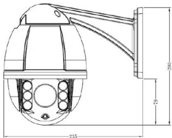
text_image
235 79 2002.2 Installation

text_image
Screws to fix bracket Buckle Screws to fix the bracket on the wall2.2.1 Wall Mounted
Installation conditions:
Wall mounted dome can be used in the hard wall structure whose thickness should be enough to install expansion bolt in indoor and outdoor environment. The wall can bear at least 4 times the weight of the dome. Install wall hanging bracket:
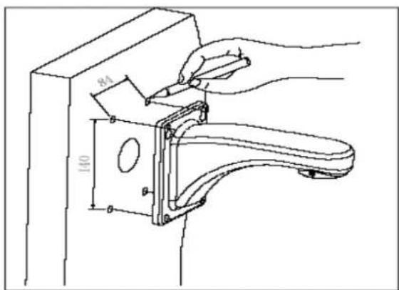
a. As shown in fig 2.3, with the installation holes in the underside of the wall hanging bracket as pattern, draw punched locations and punch.
text_image
84 140Fig 2.3
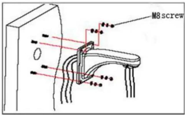
b. As shown in fig 2.4, fix the wall hanging bracket on the wall with wire and cable through it.
text_image
M8 screwFig 2.4
2.2.2 Corner Mounted
Installation conditions:
Corner mounted dome can be used in the hard wall structure with an angle of 90^ whose thickness should be enough to install expansion bolt in indoor and outdoor environment. The wall can bear at least 4 times the weight of the dome. Install corner mounted attachment and wall hanging bracket:
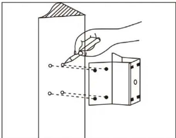
a. As shown in fig 2.5, with the installation holes in the corner mounted attachment as pattern, draw punched locations on the wall with an angle of 90^ and punch to install expansion bolt.
natural_image
Diagram showing a hand using a pen to draw a rectangular object with holes, no text or symbols presentFig 2.5
b. As shown in fig 2.6, use M8 screw nut to fix the base of corner mounted on the wall with all cables through the center holes of the corner mounted, marine glue and bracket. Enough wiring length should be left.

natural_image
Diagram of a mechanical or electrical component with internal components and wires, no visible text or symbolsFig 2.6
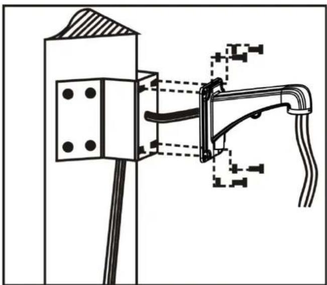
c. As shown in fig 2.7, fix the wall hanging bracket with all cables power through it on the corner mounted attachment.
natural_image
Technical line drawing of a mechanical assembly with mounting bracket and pipe connection (no text or symbols)Fig 2.7
2.2.3 Pole Mounted
Installation conditions:
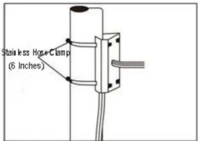
Pole mounted dome can be used in the hard pole structure in indoor and outdoor environment whose diameter should match the installation size of stainless hose clamps. Factory default is 6 inches stainless hose clamps (fit 130-152mm pillar). The pole structure can bear at least 4 times the weight of the dome. Install corner mounted attachment and wall hanging bracket:
a. As shown in fig 2.8, use the stainless hose clamps to fix the pole mounted attachment with all cable through it on the pole structure.
text_image
Stainless Hose Clamp (6 Inches)Fig 2.8
b. As shown in fig 2.9, fix the wall hanging bracket with all cables through it on the pole mounted attachment.

text_image
M8 screw wall hanging bracket M4 screwFig 2.9
2.2.4 Ceiling Mounted
Installation conditions:
Ceiling mounted dome with thick pole can be used in the hard ceiling structure whose thickness should be enough to install expansion bolt in indoor and outdoor environment. The ceiling can bear at least 4 times the weight of the dome. Install the base of ceiling and boom:
a. As shown in fig 2.10, with the installation holes in the base of ceiling as pattern, draw punched locations in the ceiling and punch to install M6 expansion bolt.

text_image
Base of CeilingFig 2.10
b. As shown in fig 2.11, at first unscrew the M4 screw at the side of the base of ceiling and split the base of ceiling and boom. Then make the three groups of cables of power, video/control and alarming into the side recessing seal groove of the ceiling connector bottom and through the core hole of the base of ceiling mounted. Fix the base of hang ceiling on the ceiling board.

text_image
Silica gel Base of CeilingFig 2.11
Note: If the dome is used in the outdoor conditions, use the silica gel on the faying surface of the base of hang ceiling and the ceiling board and around the out-holes to be sure water proof
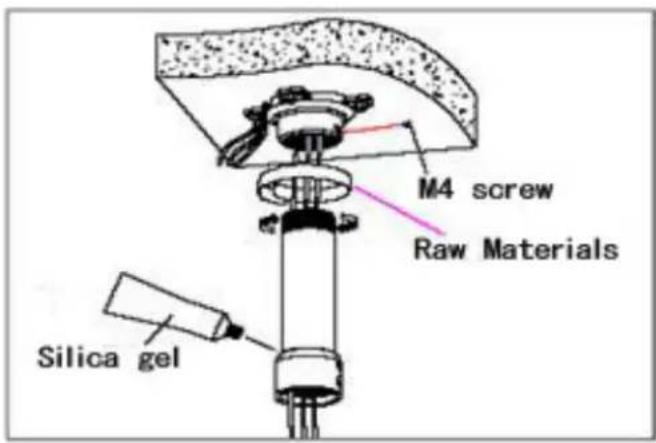
c. As shown in the fig 2.12, tighten the boom with electrical wire and cable through it on the base of ceiling and screw up the M4 screw.
text_image
M4 screw Raw Materials Silica gelFig 2.12
©Note: If the dome is used in the outdoor conditions, after using enough raw materials to wrap the thread at the upper end of boom, tighten the boom on the base of ceiling. Use the silica gel around the joint sleeve and connector of the boom to be sure water proof
2.3 Connection
2.3.1 PTZ Connection Way
Before connecting, please turn off the power and read carefully the instructions of all connected devices.

flowchart
graph TD
    A["AC24V/DC12V.50Hz"] --> B["Network Cable"]
    B --> C["Exchange Board"]
    C --> D["NVR"]
    D --> E["DISPLAY"]
    E --> F["RS485"]
    F --> A
    style A fill:#f9f,stroke:#333
    style B fill:#ccf,stroke:#333
    style C fill:#cfc,stroke:#333
    style D fill:#fcc,stroke:#333
    style E fill:#cff,stroke:#333
    style F fill:#ffc,stroke:#333
2.3.2 Connecting the Device
The device can be directly connected to the computer and the network;
Please use the cross-over cable when connecting to the computer;
Please use the straight through cable when connecting to the network.
Note: Please check the power cables are solid or not when connecting the power supply.
2.3.3 Setting the IE Browser
User can browse the video through IE, HVMS or other software, while ActiveX is required to install. Otherwise, video is not available. And, user is supposed to set the IE security level before downloading the plug-in.
-
From menu, click "tool", then choose "Internet options".
-
Then click "Security" as the follows:

text_image
Internet Options Connections General Security Programs Advanced Security Privacy Control Select a zone to view or change security settings. Internet Local Internet Trusted sites Restricted sites Internet This zone is for Internet indicators. Except how selected in trusted and restricted zones. Security level for the zone Custom Custom settings: - To change the settings, click Custom level. - To use the recommended settings, click Default level. Custom level: Default level Smart all sizes to default level 确定 取消Fig 2.13
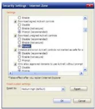
- Choose internet icon, click "Customs level". Then the follow pops up:
text_image
Security Settings - Internet Zone Settings Enable Download signed Activist controls Disable Enable (not secure) Prompt (recommended) Download unsigned Activist controls Disable (recommended) Enable (not secure) Prompt Initialize and script Activist controls not marked as safe for a Disable (recommended) Enable (not secure) Prompt Only allow approved domains to use Activist without prompt Disable Enable *Take effect after you restart Internet Explorer Reset custom settings Reset to: Medium-high (default) Export... OK CancelFig 2.14
- Change option "Download unsigned ActiveX controls" into "Enable" or "Prompt". User can optionally change "Running ActiveX controls and plug-in" into "Start" to avoid the prompt of running.
2.3.4 Install Video Software
Please take the tips as follows when installing the software of the IP camera:
(1) Download controls
First, please login to the system with IPC's default ID and password as a super user. After that, you will get the following prompt whether to install ActiveX controls. Please rightly click "loading procedure" if your system is XP.
(2) Install and run controls
Please click "Run" in the prompt box above, and the controls are to be installed to run. After that, you are able to view the video in real time.
©Note:
- The steps above are not sequential. After operating (1) and (2), if not successful, then please try the website downloading method.
- If your computer system is Microsoft Windows 2003 and you're unable to view the video after installing the controls, please start the computer's hardware acceleration.
Above all is the preparation work for the video browsing on IE.
2.4 Login IE Interface
When the system starts up for 110 seconds, please open the IE browser, input the IP camera address. The default IP is http://192.168.1.110 (Note: System default subnet mask is 255.255.255.0; default gateway is 192.168.1.110. Please correctly set the local IP address before login and access.)
Microsoft Windows [Version 6.1.7601]
Copyright (c) 2009 Microsoft Corporation. All rights reserved.

C:\Users\ASUS>ping 192.168.1.110

Pinging 192.168.1.110 with 32 bytes of data:
Reply from 192.168.1.110: bytes=32 time=1ms TTL=64
Reply from 192.168.1.110: bytes=32 time<1ms TTL=64
Reply from 192.168.1.110: bytes=32 time<1ms TTL=64
Reply from 192.168.1.110: bytes=32 time<1ms TTL=64

Ping statistics for 192.168.1.110:
    Packets: Sent = 4, Received = 4, Lost = 0 (0% loss),
Approximate round trip times in milli-seconds:
    Minimum = 0ms, Maximum = 1ms, Average = 0ms

C:\Users\ASUS>
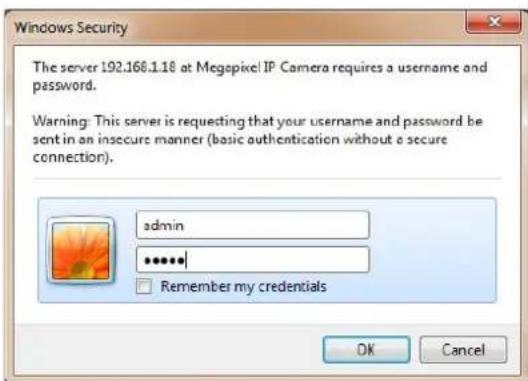
The language for login interface is consistent with the operation system. Below is the picture in Chinese operation system:
text_image
Windows Security The server 192.168.1.18 at Megapixel IP Camera requires a username and password. Warning: This server is requesting that your username and password be sent in an insecure manner (basic authentication without a secure connection). admin ****** Remember my credentials OK CancelFig 2.15
If it is the first time you run the software, please login as a super user. The system default user name is admin (password is admin); input the correct user name and password, and click "login". During login, if you would like to reset the username and password, please click "Cancel" to clear the blank. After login, you will enter the following interface:
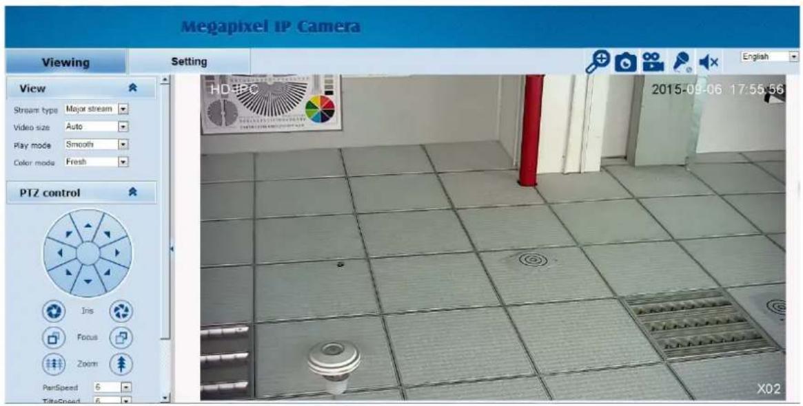
text_image
Megapixel IP Camera Viewing Setting View Stream type Major stream Video size Auto Play mode Smooth Color mode Fresh PTZ control Iris Focus Zoom PanSpeed S TideSpeed S 2015-09-06 17:55:56 X02Fig 2.16
The IP Camera supports H.264/MJPEG dual encoding format. After login, you will enter the real time video interface in the format of H.264 compression. User can click "MJPEG" button, and enter the real time video in the format of MJPEG. Please refer to picture as following:

text_image
Megapixel IP Camera Viewing Setting View Stream type Major stream Video size Auto Play mode Smooth Color mode Fresh PTZ control Iris Focus Zoom PunSpeed 6 TitleSpeed 6 English 2015-09-06 17:55:56 HD IPCFig 2.17
2.5 Browser
In the browsing interface, you can set video browse, PTZ control, commonly used shortcuts (like photography, recording, audio input, audio output, Language setting, etc.) to get the satisfying video.
2.5.1 Video Browsing
Video Browsing: For camera capture display setting, you can set the video type, video size, play mode, image color and illumination. On the browsing interface, you can click "video browsing" to enter system setting interface. Here is the picture
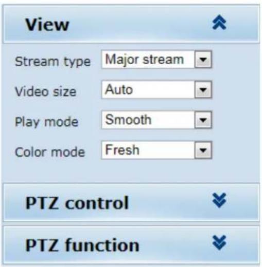
text_image
View Stream type Major stream Video size Auto Play mode Smooth Color mode Fresh PTZ control PTZ functionFig 2.18
Set the video in the menu above:
Video Type: H.264 main stream, H.264 deputy stream, MJPEG.
Video Size: screen original size 1*, original size *1/2, adaptive.
Play mode: real time, smooth.
Image Color: standard, vivid
Illumination: Standard, low light
2.5.2 PTZ Control
PTZ control: Adjust the rotation in all directions, set horizontal speed, vertical speed. The picture is as follows:

text_image
PTZ control Iris Focus Zoom Pan speed 3 Tile speed 1(S) Focus speed Middle Zoom speed MiddleFig 2.19
PTZ direction: adjust the PTZ's eight directions.
Horizontal speed: 1 — 8 optional
Vertical speed: 1 — 8 optional
2.5.3 PTZ Function
PTZ functions: preset, auto pan, pattern, tour. (Patternis not available)
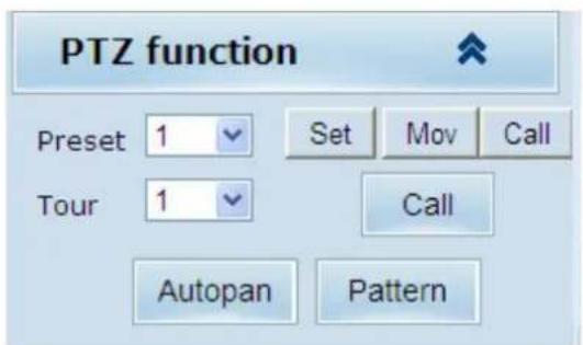
text_image
PTZ function Preset 1 Set Mov Call Tour 1 Call Autopan PatternFig 2.20
2.5.4 Common Shortcuts
Common shortcuts: 3D location photograph, record, audio input, audio output, Languages selection

text_image
EnglishFig 2.21
Frequently set common functions of the IP cameras. The storage path of photographing and recording complies with the one from setting .The snapshots are stored in the name of IP address and time of the device. For example, the file name is 20140520_221325_125_01_192.168.1.110.jpg, which means the device's IP address is 192.168.1.110 and snapshot's time is at 22:13:25:125 on May 20^th 2014.
2.6 Setting
Setting: detailed setting of system, network, IPC, audio & video, PTZ functions, alarm, user, Blog.
text_image
HD Network Camera Megapixel IP Camera Viewing Setting System Time Advanced Basic information Version: V6.03.03-CGB024200-0916 Time zone: (GMT+08:00) Beijing Product info: TI-OV20 series SerialNum : 071D3E0E02A6 Network settings MAC address: 00-2A-2A-03-01-AB IP address: 192.168.1.168 Default gateway: 192.168.1.1 Subnet mask: 255.255.255.0 Alarm settings Alarm server IP: 0.0.0.0 Alarm contact: Local contact NTP settings NTP server IP: 0.0.0.0 H.264 video settings Major stream parameters: Resolution: 1920x1080 Frame rate: 25 Bit rate: 5120Kbps GOV number: 30 Minor stream parameters:Fig 2.22
2.6.1 System
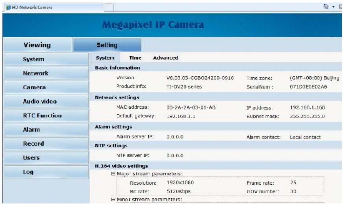
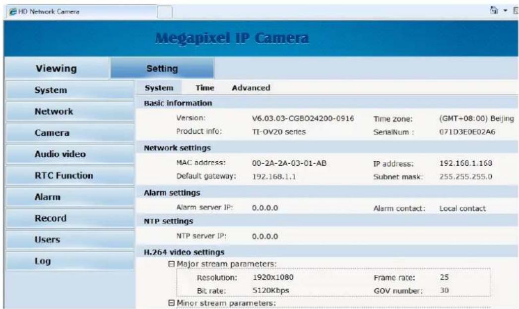
System: upgrade the system info, time and maintenance.
System info: The initial interface of system setting is the display interface of system info. User can learn more about the setting info, like basic info, network parameter alarm setting, NTP setting, H.264 video parameter setting, MJPEG video parameter setting.
text_image
MEgapixel IP Camera Viewing Setting System Time Advanced Basic information Version: V6.03.03-CGBO24200-0916 Time zone: (GMT+08:00) Beijing Product info: TI-OV20 series SenaiNum : 071D3E0E02A6 Network settings MAC address: 00-2A-2A-03-01-AB IP address: 192.168.1.168 Default gateway: 192.168.1.1 Subnet mask: 255.255.255.0 Alarm settings Alarm server IP: 0.0.0.0 Alarm contact: Local contact NTP settings NTP server IP: 0.0.0.0 H.264 video settings Major stream parameters: Resolution: 1920x1080 Frame rate: 25 Bit rate: 5120Kbps GOV number: 30 Minor stream parameters:Fig 2.23
Basic Info: The IPC's version number, time zone, product series, serial number.
Network parameter: MAC address, IP address, default gateway, subnet mask.
Alarm setting: Alarm server IP, alarm correlation.
NTP setting: NTP server IP.
H.264 video parameter: main stream/sub stream resolution, frame rate, bit rate, I/P rate.
MJPEG parameter setting: resolution, frame rate.
Time: time zone setting, NTZ setting, real-time synchronization parameter setting.

text_image
Viewing Setting System Time Advanced Time zone settings Time zone: (GMT+08:00) Beijing, Chongqing, Hong Kong, Urumqi, Inkutsk, Ulaar Daylight saving time: On Off Save Cancel NTP set NTP server IP: 0.0.0.0 Sync time: 23 : 59 : 00 Sync interval(hours): 24 Save Cancel Sync now Device time: 2013-10-08 09:54:18 Local PC time: 2013-10-08 09:54:18Fig 2.24
Time zone setting: select your time zone from the drop down list, click "setting" and it's done. 26pcs
time zones are optional for setting, range "GMT-12:00\~GMT\~GMT+13:00". Of all, GMT+08:00 is China Beijing time. The default setting is GMT standard time. If your local time is daylight saving time, please click "automatically adjust clock for daylight saving changes" option. NTP setting: set NTP server IP is the same with the device's IP address. Synchronization time: set the time for synchronization. Synchronization time intervals: every a time period (6--12—24) for time synchronization.
Real-time synchronization: Synchronize the time of the device. You can choose NTP or localsynchronization.
The device's time: display existing time.
Local PC time: error correct the system time and local pc time. Click "setting" button to synchronize.
NTP Synchronization: whether to start NTP service. Select to start NTP service, otherwise do not select. If NTP service starts, you can input NTP server address in the IP field, and click "setting" button. After NTP is activated, the system corrects the time with NTP automatically.
Local synchronization: set camera time to synchronize local PC.
Maintenance: contains upgrading the device's software, restoring factory settings and restarting the system.

text_image
Viewing Setting System Time Advanced File import 浏览... (Please choose upgrade file of TI series.) Submit Factory settings Press the button to reset all the parameters to the factory default settings. Maintain current IP: ✓ Reset Reboot Press the button to reboot the system, the window will reload after it. Reboot System Network Camera Audio video RTC Function Alarm Record Users LogFig 2.25
Software upgrade: The IP camera's network service system can enjoy free remote software upgrade, which reduces the cost of system maintenance.
First, user can remotely submit system upgrade request via internet. According to user's submission, we'll send the device's relative edition upgrade for confirmation, and provide the latest software downloading, helping upgrade the IP Camera. User can upgrade the system as the following steps:
Click "Browsing" icon, and select IFU upgrade file and upload it.
Please restart the device after upgrading.
Restore factory setting: The device's network system provides online resetting functions, through which all system settings can be restored to factory default. It is a great convenient to the clients. If you select to keep the IP address, it is the existing address; while if you cancel it, it will be restored to factory default address: 192.168.1.110.
System restart: click "restart" button, the system restarts. The time is around 80 seconds.
After that, the webpage is closed.
2.6.2 Network
Network: The device's relevant network parameter setting, including Network、FTP、SMTP/HTTPS、QoS、IGMP、SIP、DDNS、PORT.

text_image
Network FTP SMTP QoS IGMP PORT DDNS CloudLens Network DHCP: On Off IP address: 192.168.1.115 Subnet mask: 255.255.255.0 Default gateway: 192.168.1.1 Primary DNS server: 192.168.1.1 Secondary DNS server: 0.0.0.0 Save CancelFig 2.26
Network: setting of the device's network parameter.

text_image
Network DHCP: On Off IP address: 192.168.1.113 Subnet mask: 255.255.255.0 Default gateway: 192.168.1.1 Primary DNS server: 192.168.1.1 Secondary DNS server: 0.0.0.0 Save CancelFig 2.27
DHCP: Dynamic Host Configuration Protocol, one of TCP/IP, mainly allocating dynamic IP address for network clients. Select "on", the camera's IP address and the subnet mask cannot be modified, but automatically allocated by the host. Select "off", you're supposed to set the network data by yourself and make sure the IP address and gateway address on the same segment.
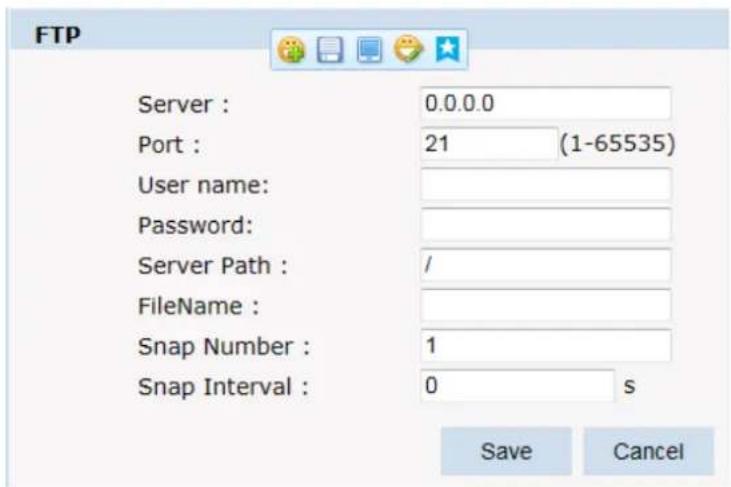
FTP: FTP (File Transfer Protocol) is application layer protocol, based on transport layer for client's service. FTP is in charge of transferring files. The IP camera supports FTP photo uploading function on alarming. On FTP interface, set the server address, username and password, activate FTP alarm at alarm setting, the FTP photo uploading can be realized.
text_image
FTP Server : 0.0.0.0 Port : 21 (1-65535) User name: Password: Server Path : / FileName : Snap Number : 1 Snap Interval : 0 s Save CancelFig 2.28
SMTP: SMTP belongs to TCP/IP, help to find the next destination for each computer when sending or transiting letters.

text_image
SMTP Server IP: 0.0.0.0 From: frommail@test.com To: tomail@test.com CC: ccmai@test.com Authentication: On Off User name: test Password: ***** Save CancelFig 2.29
Server IP: set up mail server IP.
✿ Sender: set up the email address of the sender.
◆ Authentication: Turn on or off the authentication function via mail server verification.
User name: Sender's name. User can set by itself.
✨ Password: Set sender's password.
✿ TO: Recipient's mail address.
CC: mail's address.
©Note: No restrictions for setting username and password.
After setting, please click "set" to effect the setting.
If the user selects "mail" at "Alarm Setting", the system would send emails according to the SMTP setting.
HTTPS: a safe-protection channel, shortly, a secure version of HTTP.

text_image
CA certificate import CA certificate: 浏览... SubmitFig 2.30
QoS: Quality of Service, a kind of network secure mechanism, a technology of solving network delay and congestion.

text_image
QoS QoS option: Normal service Save CancelFig 2.31
IGMP: It is a multi-cast protocol of internet family, helping IP Host report their membership to the adjacent routers.

text_image
IGMP Stream type: Major Stream State: On Off MultiCast: IP address: 0.0.0.0 RTP port: 0 Save CancelFig 2.32
text_image
Position Information Position name: test Longitude: 112.10 Latitude: 45.30 Save CancelFig 2.33
DDNS: The user's dynamic IP address is mapped to a fixed domain name resolution service.
When connecting network each time, the client's procedure would pass the host's IP address to the server's procedure which provides DNS service and realize domain name resolution. That is, DDNS captures the changing IP address and corresponds the domain name, which is how other clients communicate.

text_image
DDNS DDNS State: Method: CamAnywhere Username: test Password: ••••• Domain: infisecu.oicp.net SaveFig 2.34
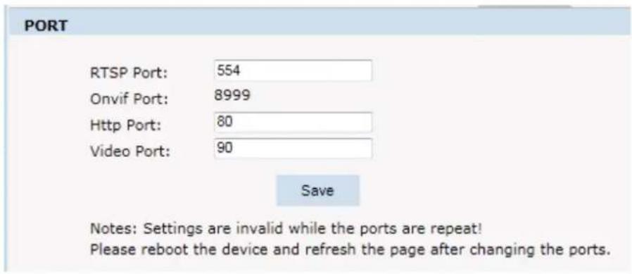
PORT: an interface, passing data between the computer and other devices (e.g. Printer, mouse, keyboard, monitors), among network, or other computers in connection.
text_image
PORT RTSP Port: 554 Onvif Port: 8999 Http Port: 80 Video Port: 90 Save Notes: Settings are invalid while the ports are repeat! Please reboot the device and refresh the page after changing the ports.Fig 2.35
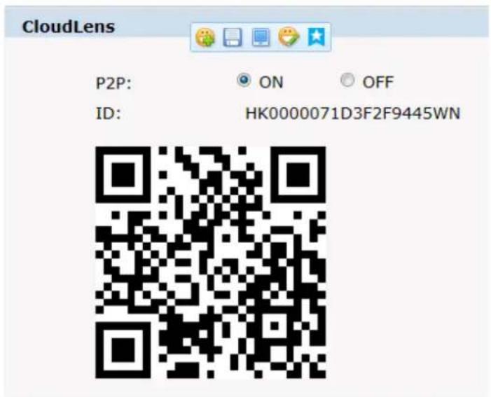
Cloudlens
text_image
CloudLens P2P: ON OFF ID: HK0000071D3F2F9445WNFig 2.36
2.6.3 Management Software
This section is very simple, and here is the introduction:
Software initial user name is admin, while password is 123456.
After login, you can find "search" button on the top of the interface, and click to search all IP cameras in the LAN area.
Among all the camera lists found out, tick the ones you want to manage and click "save" on the left upper corner. Then turn off the dialog to enter the interface, and double click the IP camera and you will open the video.
Other relative settings are very simple to set. Please operate by the reference of the interface prompts.
2.6.4 IP Cameras
IP Cam: setting of the camera parameter, like basic settings, expose settings, effect setting, white balance and reset.

text_image
Viewing Setting System Network Camera Video&Audio PTZ Function Alarm Record User management Log Basic setttins Expose settings Effect settings White balance Reset -D IPC: 2015 09 15 23.51 FlickerFrequency: 50Hz 60Hz AntiFalse Color: On Off CVBS Output: PAL AntiFog: On Off Vertical Mirror: On Off LensShadeCorr: On Off Horizontal Mirror: On Off LensDistortCorr: On Off Back Light: On Off Dig-ImgStabilize: On Off Digital WDR: On Off WDR Level: 85Fig 2.37
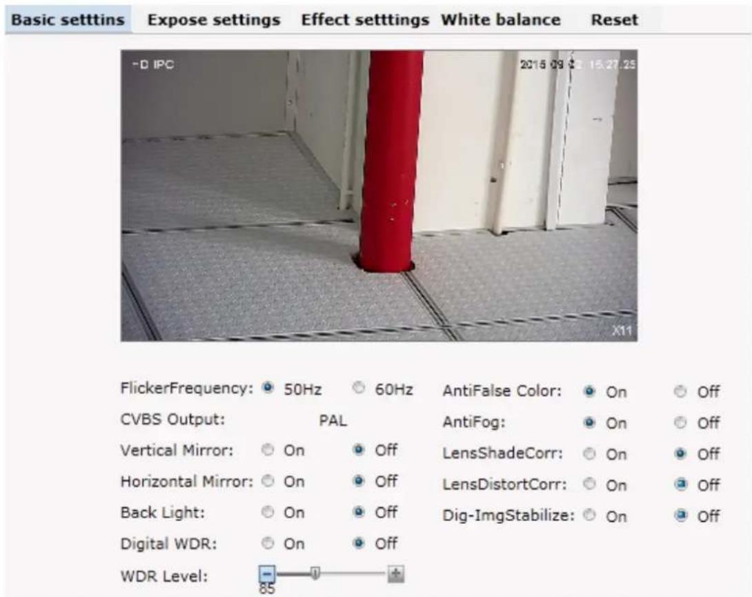
Basic set: Enable and disable setting of camera system, noise, mirror, BLC and other function (this depends on the function of zoom module).
text_image
Basic setttins Expose settings Effect setttings White balance Reset -D IPC 2016 09 15.27.25 FlickerFrequency: 50Hz 60Hz AntiFalse Color: On Off CVBS Output: PAL AntiFog: On Off Vertical Mirror: On Off LensShadeCorr: On Off Horizontal Mirror: On Off LensDistortCorr: On Off Back Light: On Off Dig-ImgStabilize: On Off Digital WDR: On Off WDR Level: -85 +Fig 2.38
Power Frequency: 50HZ domestic use; 60HZ abroad use.
Horizon Mirror: image horizontal mirror display.
Vertical Mirror: image vertical mirror display.
BLC: divided into different zones and each zone expose separately. BLC offers ideal exposure in front of strong back light. There is low, medium and high level optional.
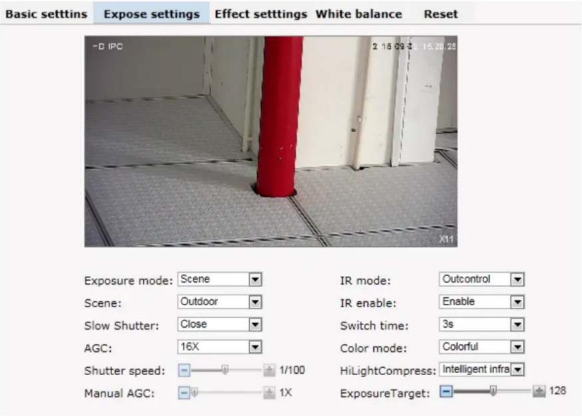
Expose settings: expose mode, Color to Black, Scene select, and AGC setting.
text_image
Basic setttins Expose settings Effect settings White balance Reset -D IPC 2 15.09 € 15.28.25 X11 Exposure mode: Scene IR mode: Outcontrol Scene: Outdoor IR enable: Enable Slow Shutter: Close Switch time: 3s AGC: 16X Color mode: Colorful Shutter speed: 1/100 HiLightCompress: Intelligent infra Manual AGC: 1X ExposureTarget: 128Fig 2.39
Expose set: program mode, for normal video mode; shutter mode, for fast moving objects.
Scene Select: Indoor, eliminate indoor lighting flash; Outdoor, eliminate outdoor overexposure.
Slow shutter: shutter setting, default is off.
AGC: A kind of control method of automatically adjusting amplifier circuit with signal intensity. The higher the gain is, the brighter the evening image becomes. You can adjust the image according to the real requirement. Higher gain dims the image.
IR mode: change IR mode
IR enable: enable and disable IR LED
Switch time: IR on and off switching duration
Color mode: change color mode
HLC: Hight light compress
Exposure Target
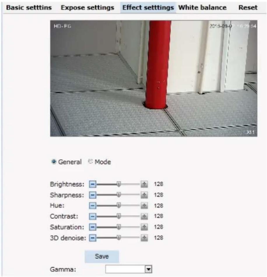
Effect Setting: setting of image sharpness, brightness, contrast, saturation.
text_image
Basic setttins Expose settings Effect setttings White balance Reset HD-PC 2015-09-0 16:29:54 X11 General Mode Brightness: - - - + 128 Sharpness: - - - + 128 Hue: - - - + 128 Contrast: - - - + 128 Saturation: - - - + 128 3D denoise: - - - + 128 Save Gamma: -Fig 2.40
Brightness: unit projected area of brightness intensity would bring the overall brightness of the image. Over higher brightness would cause the insufficient permeability.
Sharpness: also called "resolution", which reflects the image plane clarity and edge sharpness. Adjust the sharpness higher, the contrast details on the plane image become higher and then the image looks much clear. If the sharpness is set too high, white trim lines would appear next to both black lines and you will get distorted glare image.
Hue: adjust the color
Contrast: It is critical to the image effect. Generally, the higher the contrast is, the more clear vivid the image becomes; small contrast brings grey screen quality.
Saturation: refers to the vividness of the color, also known as the purity of the color. The higher the colorcontent is, while the larger the saturation is; the higher the achromatic color is, while the smaller the
saturation is.
3D Noise: Noise reduction adjust during night
White Balance: Balance the white. Regardless of any light, the white objects would return to white color.

text_image
Basic settins Expose settings Effect settings White balance Reset HD-PC 2015-09-02 X11 Mode: Auto Red gain: 24 Blue gain: 26Fig 2.41
White Balance: auto, cloudy, Day (D65), Day (50), Fluorescent Light, Filament Lamp, Sun Up, Manual.
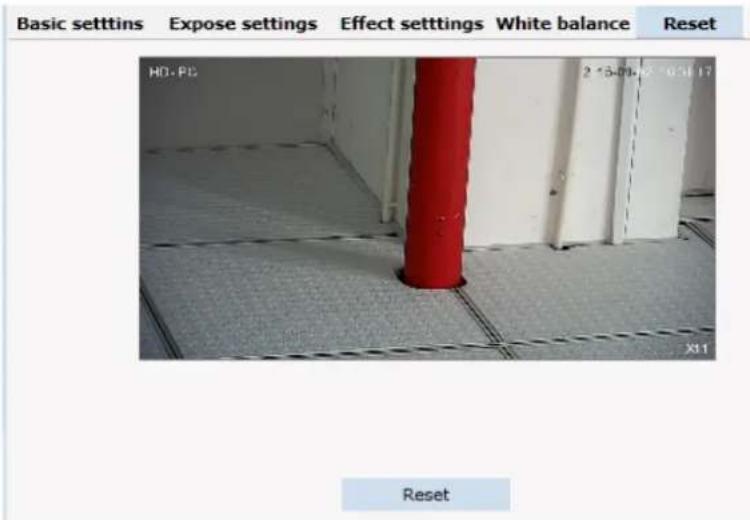
Reset: fix the camera data. Click "Reset" to return to factory default.
text_image
Basic setttins Expose settings Effect setttings White balance Reset HD.PG 2 *5-00* 6 * 031 17 X11 ResetFig 2.42
2.6.5 Audio & Video
Audio & Video: setting of camera audio, video, OSD, and path.
text_image
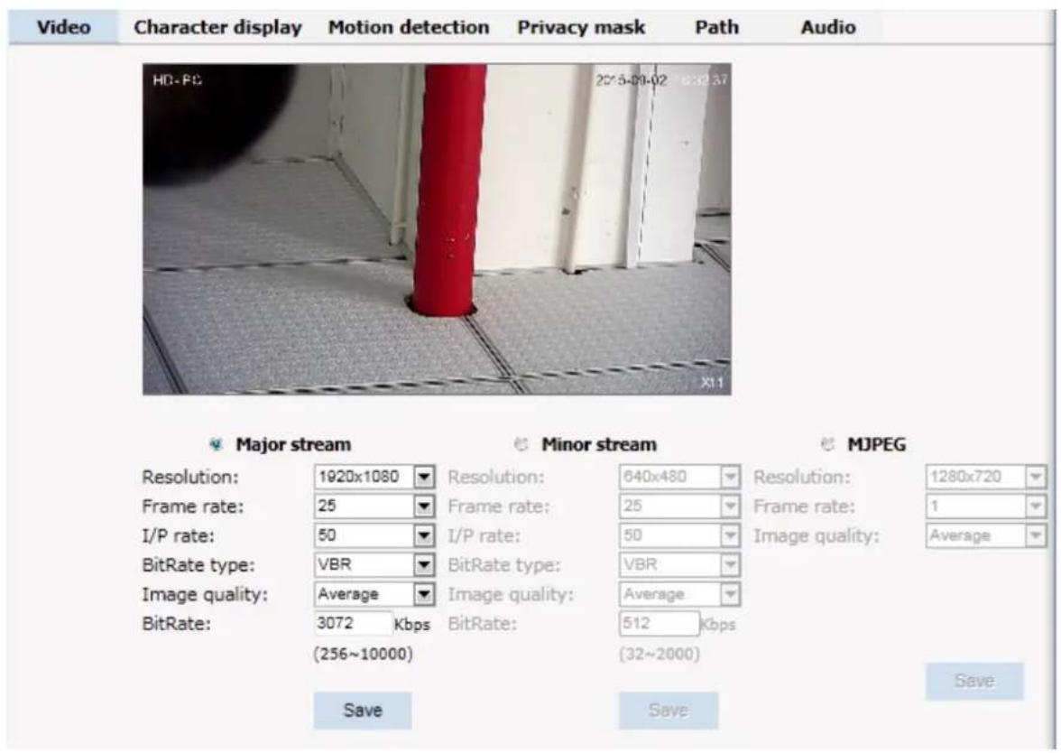
Video Character display Motion detection Privacy mask Path Audio HD-PC 2015-09-02 0:32:37 X11 Major stream Minor stream MJPEG Resolution: 1920x1080 Resolution: 640x480 Resolution: 1280x720 Frame rate: 25 Frame rate: 25 Frame rate: 1 I/P rate: 50 I/P rate: 50 Image quality: Average BitRate type: VBR BitRate type: VBR Image quality: Average Image quality: Average BitRate: 3072 Kbps BitRate: 512 Kbps (256~10000) (32~2000) Save Save SaveFig 2.43
Video: Main Stream, Minor Stream, MJPEG.
Resolution: 1920*1080, 1280*1024, 1280*960, 1280*720, 640*480.
Frame: the number of IP Cam's processing compressed frames. If the number of the frame is set bigger, the image would become more continuity, but it reduces the performance of CPU processing other events. If the frame rate is set smaller, the continuity get worse, but CPU could process more other events. Recommendation: NTSC system: 30; PAL: 25.
I/P Rate: user can change the I/P rate according to the demand, do not recommend to change the setting if user are not professional.
Image quality: change the setting to choose the picture quality display
Bitrate Type: VBR — constant image quality, normal use when the bandwidth is sufficient. CBR — image transmission with fixed bandwidth.
Bit rate: 512K, 1024K, 2048K, 3072K, 4096K, 5120K, 6144K. The bit rate is higher, the footprint is bigger, while the image is better. 720P/2M 1080P/4M are commonly used. I/P rate: the contrast of I frame and P frame. The bigger the ratio is, the data is smaller. Recommendation: set 15.
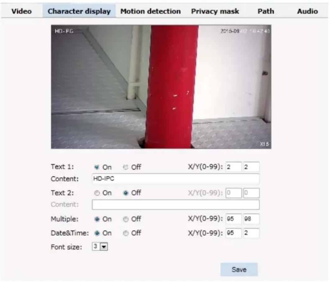
Text Overlay: Text, time, date can be displayed on the screen. XY 2 dimension stands for position.
text_image
Video Character display Motion detection Privacy mask Path Audio HG-PC 2015-09-02 10:42:48 X18 Text 1: On Off X/Y(0-99): 2 2 Content: HD-IPC Text 2: On Off X/Y(0-99): 0 0 Content: Multiple: On Off X/Y(0-99): 95 98 Date&Time: On Off X/Y(0-99): 95 2 Font size: 3 ▼ SaveFig 2.44
OSD setting includes: text OSD, date OSD and time OSD.
Text OSD: set the subject and position. Choose On or Off to display the text or not.Input the content in the form after the text, where 24 characters can be displayed. X and Y coordinate is based on the zero coordinate on the upper left corner of the image. X and Y coordinate can be set to an integer between 0 to 99.
After setting the text content and coordinate, click display and the following setting. Then the text would appear on the real live video. If you want to cancel it, please tick off the option and choose setting.
Date OSD: set date, position, ON or OFF of the date display.
Time OSD: set the position of time display, ON or OFF of the time display.
Motion Detection: commonly used in unmanned video and alarm.

text_image
Video Character display Motion detection Privacy mask Path Audio HD-PC 2015-09-02 16:44:38 X15 Zone 1: Draw Name: 1 Sensitivity: (Most sensitive) Save Cancel Zone 2: Draw Name: Sensitivity: (Most sensitive) Save Cancel Zone 3: Draw Name: Sensitivity: (Most sensitive) Save Cancel Zone 4: Draw Name: Sensitivity: (Most sensitive) Save CancelFig 2.45
【Sensitivity】: Setting motion detection sensitivity. The sensitivity can be set from 1 to 100. The smaller the number is, the higher the sensitivity is. Recommendation: 15.
【Zone】: You can set 4 motion detection zones. Each of them can be drawn and set with a mouse. When the set zone detects motion, the alarm is triggered and the log is recorded.
【Motion detection switch】: You can set or cancel motion detection alarm.
☺Note: With detection alarm on and 5 seconds thereafter, the zone begins to detect themotion.
Privacy Zone: setting the privacy zone of the camera. This zone can not move. It is available if PTZ is in a fixed place.

text_image
Video Character display Motion detection Privacy mask Path Audio HD-PC 2015-09-02 16:45:20 Zone 1: Draw Name: Zone 2: Draw Name: Zone 3: Draw Name: Zone 4: Draw Name: Save Cancel Save Cancel Save CancelFig 2.46
IP Cameras support privacy zone function. When a special zone is not allowed to be seen by the operator, you can use this function. Through MASK setting, the specific zone is covered and the operator cannot see the video of the zone.
【Zone】: You can set 4 privacy zones. Each of them can be drawn and set with a mouse.
Select save and the zone is covered. You can set the coordination of the privacy zone as well and click save to effect immediately.
Path: storage path of IE recording and snapshot.

text_image
Video Character display Motion detection Privacy mask Path Audio HD-PC 2015-09-02 16:40:05 Photo saving path: C:\IPC_PlayerAX\Picture Browse... Format: .jpg Video saving path: C:\IPC_PlayerAX\Video Browse... Format: .avi SaveFig 2.47
The default is C drive control folder. Click browse to re-select the storage path. For the type of the file, photos is jpg/bmp and video is avi/ifv.
2.6.6 PTZ Function
PTZ function: preset, auto tour, PTZ protocol.
Preset: When the PTZ patrols to an important spot and commands a preset, the PTZ would record the location and status to build up the link. When the command is shot, the camera fast patrols to the spot and the camera returns to that memory. The operator obtains the spot fast and easily. 254 preset positions are optional.

text_image
Preset Auto tour PTZ protocol HD-PC 2015-09-02 7:49:01 X15 No.: 1 Title: hjhk Save Set Call Delete Iris Focus Zoom Pan speed 6 Tilt speed 6Fig 2.48
Auto Tour:
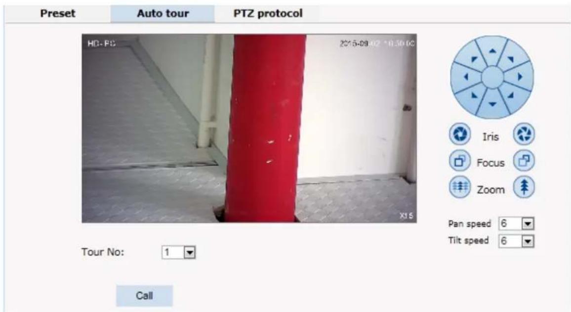
text_image
Preset Auto tour PTZ protocol HD-PC 2015-09-02 18:30:00 X15 Tour No: 1 Call Iris Focus Zoom Pan speed 6 Tilt speed 6Fig 2.49
Protocol set:

text_image
Preset Auto tour PTZ protocol HD-FC 2015-09-02 16:30:40 X15 Address: 1 Protocol: Pelco-D Baud rate: 9600 3D Protocol: Pelco-DH User mode: HK-TST Iris Focus Zoom Pan speed 6 Tilt speed 6Fig 2.50
2.6.7 Alarm
Alarm: grounded circuit and open circuit for I/O. Set net contact or local contact.

text_image
Alarm configuration I/O In 1: Grounded circuit Alarmout contact: Local contact Alarm server IP: 0.0.0.0 Save Alarm out contact I/O out 1 Mail Localsave FTP Audio Select all I/O In 1 Motion area 1 Motion area 2 Motion area 3 Motion area 4 Save| Start time | End time | |
| □ Sun. | 00 : 00 | 23 : 59 |
| □ Mon. | 00 : 00 | 23 : 59 |
| □ Tue. | 00 : 00 | 23 : 59 |
| □ Wed. | 00 : 00 | 23 : 59 |
| □ Thu. | 00 : 00 | 23 : 59 |
| □ Fri. | 00 : 00 | 23 : 59 |
| □ Sat. | 00 : 00 | 23 : 59 |
| □ Everyday | 00 : 00 | 23 : 59 |
Fig 2.51
The IP camera supports 2 channel alarm in. User can set grounded or open circuit for each I/O.
Alarm out contact: transmission method of alarm signal.
Local contact: local alarm out. Default local contact.
Net contact: internet transmission.
©Note: The function requires the synchronous use of digital video management software, e.g. HVMS. Choosing net contact, user is supposed to set the alarm IP as HVMS-CMS IP.Finishing data set of HVMS, the relay switch can be remotely controlled. For more details, please refer to HVMS manual.
Alarm IP: set the IP address of the alarm.
User can set each channel signal alarm in or alarm method of each motion detection: Alarm in 1 (for net contact, the alarm in 1 is ineffective), sending emails, FTP uploading, audio and others. The setting takes into effect after clicking setting button.
Alarm Schedule: user can set alarm schedule by day and exactly time.
2.6.8 User
User: Administrator's authority to operate the camera.
| Add user | |||
| Num | User name | Property | Operation |
| 1 | admin | ||
Fig 2.52
Add user: click the image " , you will get the following dialog:
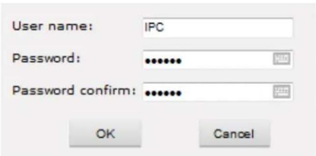
text_image
User name: IPC Password: ••••••• Password confirm: ••••••• OK CancelFig 2.53
Input user name and password.
| Add user | |||
| Num | User name | Property | Operation |
| 1 | admin | ||
| 2 | IPC | ||
Fig 2.54
2.6.9 log
Log: recording of each operation
| Viewing | Setting | |||
| System | Date | Time | Log | |
| Network | 2013 - 10 - 06 | 19 : 28 : 59 | system start completely! | |
| 2013 - 10 - 06 | 19 : 28 : 57 | webs start completely!!! | ||
| Camera | 2013 - 10 - 06 | 19 : 28 : 55 | app_main start completely ! | |
| 2013 - 10 - 06 | 19 : 28 : 54 | Alarm input 1 | ||
| Audio video | 2013 - 08 - 01 | 08 : 05 : 42 | change ip !!! | |
| 2013 - 08 - 01 | 08 : 05 : 09 | system start completely! | ||
| RTC Function | 2013 - 08 - 01 | 08 : 05 : 04 | webs start completely!!! | |
| 2013 - 08 - 01 | 08 : 05 : 03 | app_main start completely ! | ||
| Alarm | 2013 - 08 - 01 | 08 : 05 : 02 | Alarm input 1 | |
| 2013 - 08 - 01 | 08 : 05 : 08 | system start completely! | ||
| Record | 2013 - 08 - 01 | 08 : 05 : 05 | webs start completely!!! | |
| 2013 - 08 - 01 | 08 : 05 : 03 | app_main start completely ! | ||
| Users | 2013 - 08 - 01 | 08 : 05 : 03 | Alarm input 1 | |
| Log | ||||
Fig 2.55
3. Function Instruction
3.1 Basic Function
- Dome Running
Control joystick or up, down, left and right key in the keyboard.
- Zoom
Press ZOOM- button to make the lens farther and minify the scene.
Press ZOOM+ button to make the lens closer and magnify the scene.
- Focus
After FOCUS- button is pressed, the object in vicinity will become clearer while the object far away will become ambiguous.
After FOCUS+ button is pressed, the object far away will become clearer while the object in vicinity will be ambiguous.
- Iris
Press IRIS- to gradually shrink the iris and decrease the image brightness.
Press IRIS+ to enlarge the iris and increase the image brightness.
- Preset Point
Setting preset press button "preset" + "number" + "Enter".
Calling preset press button "call"+" number"+"Enter".
Deleting preset press button "clear" + "number" + "Enter".

Remark: Some preset points are used tentatively for special functions.
3.2 Special Function
The follow presets are predefined as special function, please shot+ preset No+ enter to enable those functions:
| PREST | FUNCTION | PRESET | FUNCTION |
| 34 Reset 84 | Turn on far light | ||
| 35 | Run Wiper | 85 | Turn on near light |
| 36 | Stop Wiper | 91(31) | Call A-B scan |
| 75 | Pattern 1 | 1 | Set left point of A-B scan |
| 76 | Pattern 2 | 2 | Set right point of A-B scan |
| 77 | Pattern 3 | 96 | Guard tour 3 |
| 78 | Pattern 4 | 97 | Guard tour 2 |
| 81(41) | Auto Day/Night | 98(38) | Guard tour 1 |
| 82(42) | Night Mode | 99 | Pan scan |
| 83 | Day Mode |
Remark: If use some other equipments to control IR dome, some special functions probably can't be effective because of the limit of protocol.
Appendix I Anti-lightning, Anti-surge
This product is extremely air discharge and lightning protection with TVS tube technology, which can effectively prevent the transient lightning below voltage 3000V, surge and damages caused by other types of pulse signals.
However, necessary protective measures should be made in the premise of ensuring electrical safety for outdoor installation according to the actual situation:
- Signal transmission line must be at least 50 meters far away from the high-voltage equipment or high voltage cable.
● Try to choose outdoor wiring lay down along the roof line. - Way of sealed steel pipe buried wiring is used in the area which opened, and steel pipe units grounded in one point. Overhead wiring is absolutely prohibited.
- In the strong thunderstorms area or areas with high induced voltage (such as high voltage substations), measure of installation of additional high power lightning protection equipment and lightning rod must be taken.
● Lightning protection and grounding of outdoor devices and lines must take the lightning-protection requirements of buildings into consideration, and comply with the related national standards and industry standards. - System must be equipotent grounding. Grounding device must meet dual requirements of anti-interference and electrical safety, and should not be shorted or mixed with the adjacent lines in the strong power grid. When system is independently grounded, grounding impedance should be less than 4 , and cross-sectional area of grounding conductor must be not less than 25m^2 .

text_image
Video Arrester Comm. LightingArrester Power Arrester Power ground wire is not more than 4Ω Steel Sheath Lighting Rod 45degree Dome must be under45degree rangeFig 25
Appendix II Clean Transparent Cover
In order to assure a clear image of dome, the under cover of dome should be cleaned regularly.
- Be careful when cleaning and hold the outer ring of under cover by hands to avoid directly touching with it. Because the acid sweats of finger membrane may corrode the surface coating of under cover.
Hard tool scratching the under cover may lead to blurring the images of dome so that affecting image quality. - Please uses a soft enough dry cloth or other alternatives to wipe internal and external surface.
- If dirt is serious, user can use a mild detergent. Any senior furniture cleaning products can be used to clean the under cover.
Appendix III Exception Handling
| Issue Possible Reason Solution | ||
| After power is applied, there is no action (self-test) | Cable harness is improperly connected | Verify that the orientation of the connector input |
| Input power voltage is too low | Verify the voltage of the input power | |
| Power supply does not work Change a new power supply | ||
| PTZ has not finish self-test | Please wait 90 seconds | |
| Noise after self-testing | Mechanical obstruction Verify and correct it | |
| Camera module is not installed correct | Correct | |
| Low power Change the correct power supply | ||
| Image is no stable. | Low power | Check the power supply or make sure the power input is AC24V / DC12V |
| Network cable properly connected. | Verify the connection of the network cable | |
| Image is blurring | Camera is on manual focus Change to auto focus | |
| The lens is dusted Clean the lens | ||
| Controlling the dome is not smooth | Power is too low | Change the AC24V / DC12V Power supply |
| Communication distance is too long | Make sure the distance is in the allowed range | |
| No video signal | Wrong installation of plug-in for video | Refer to the installation part, use controls and reset up the plug-in |
| IP address fails to ping | Set default as 192.168.110 segment, or revise the IP address | |
| IP address pings through, but no video | Check whether the video is recorded online or stop the recording | |
| IP address conflicts with other devices | Set one IP different from others | |
Copyright Statement
This copyright is merely belong to the manufacturer. Without permission, please don't plagiarize or copy the contents of this book in any form or by any means.
The company follows the policy of continuous development. Therefore, the company reserves the right to modify or improve the products described in this manual without notice.
The content of manual is offered according to the "current state". Unless applicable law otherwise specified, the company does not make any kind of clear or tacit reassurance about the accuracy, reliability and contents of this manual. The company reserves the right to revise or recoup this manual at any time without notice.