
Concerta B1 - Subwoofer Revel - Free user manual and instructions
Find the device manual for free Concerta B1 Revel in PDF.


| Product Type | Powered Subwoofer |
| Brand | Revel |
| Model | Concerta B1 |
| Woofer Size | 12" (305mm) with anodized-aluminum diaphragm |
| Woofer Excursion | 1-1/2" (38.1mm) peak-to-peak |
| Amplifier Power (RMS) | 250W (300W dynamic) |
| Frequency Response | +/-0.5dB in pass-band, -3dB at 36Hz, -6dB at 32Hz, -10dB at 29Hz (anechoic) |
| Low-Pass Crossover | 50Hz - 150Hz, 24dB/octave, continuously variable |
| Phase Switch | 0° or 180° |
| Equalization | Parametric: adjustable frequency, bandwidth, level |
| Input Connectors | Sub In (low-pass disabled), L/R (low-pass enabled) – RCA |
| Power Requirements | 120V~60Hz, 2A or 220-240V~50/60Hz |
| Dimensions (H x W x D) | 17-3/4" x 15-3/4" x 14" (45.0 x 40.0 x 35.6 cm) including feet and grille |
| Weight | 51 lb (23.15 kg) |
| Cabinet Material | Medium-density fiberboard (MDF) with internal bracing |
| Finish | Vinyl |
| Wireless Option | Compatible with optional TX1 transmitter |
| Standby Power Consumption | Auto standby after 10 minutes of no signal; LED red in standby, green when on |
| Included Accessories | Power cord, RCA patch cable |
| Cleaning Instructions | Wipe cabinet and grille with dry soft cloth; do not use cleaning products or polishes |
| Warranty | Varies by country; contact local Revel retailer |
Frequently Asked Questions - Concerta B1 Revel
User questions about Concerta B1 Revel
0 question about this device. Answer the ones you know or ask your own.
Ask a new question about this device
Download the instructions for your Subwoofer in PDF format for free! Find your manual Concerta B1 - Revel and take your electronic device back in hand. On this page are published all the documents necessary for the use of your device. Concerta B1 by Revel.
USER MANUAL Concerta B1 Revel
IMPORTANT SAFETY PRECAUTIONS READ FIRST!
- Read these instructions.
- Keep these instructions.
- Heed all warnings.
- Follow all instructions.
- Do not use this apparatus near water.
- Clean only with a dry cloth.
- Do not block any ventilation openings. Install in accordance with the manufacturer's instructions.
- Do not install near any heat sources such as radiators, heat registers, stoves or other apparatus (including amplifiers) that produce heat.
- Do not defeat the safety purpose of the polarized or grounding-type plug. A polarized plug has two blades with one wider than the other. A grounding-type plug has two blades and a third grounding prong. The wide blade or the third prong is provided for your safety. If the provided plug does not fit into your outlet, consult an electrician for replacement of the obsolete outlet.
-
Protect the power cord from being walked on or pinched, particularly at plugs, convenience receptacles and the point where they exit from the apparatus.
-
Only use attachments/accessories specified by the manufacturer.
-
Use only with the cart, stand, tripod, bracket or table specified by the manufacturer or sold with the apparatus. When a cart is used, use caution when moving the cart/apparatus combination to avoid injury from tip-over.

-
Unplug this apparatus during lightning storms or when unused for long periods of time.
-
Refer all servicing to qualified service personnel. Servicing is required when the apparatus has been damaged in any way, such as power supply cord or plug is damaged, liquid has been spilled or objects have fallen into the apparatus, or the apparatus has been exposed to rain or moisture, does not operate normally or has been dropped.
-
Do not expose this apparatus to dripping or splashing and ensure that no objects filled with liquids, such as vases, are placed on the apparatus.
-
To completely disconnect this apparatus from the AC Mains, disconnect the power supply cord plug from the AC receptacle.
-
The mains plug of the power supply cord shall remain readily operable.
-
Do not expose batteries to excessive heat such as sunshine, fire or the like.

The lightning flash with arrowhead symbol, within an equilateral triangle, is intended to alert the user to the presence of uninsulated "dangerous voltage" within the product's enclosure that may be of sufficient magnitude to constitute a risk of electric shock to persons.

The exclamation point within an equilateral triangle is intended to alert the user to the presence of important operating and maintenance (servicing) instructions in the literature accompanying the product.
WARNING: To reduce the risk of fire or electric shock, do not expose this apparatus to rain or moisture.
ABOUT THE REVEL® CONCERTA™ B1 SUBWOOFER
Thank you for purchasing the Revel Concerta B1, a high-performance powered subwoofer that perfectly augments Revel Concerta Series loudspeakers in stereo music or home theater entertainment systems. The B1's adjustable controls and multiple connection options also allow you to optimize the subwoofer's performance in any system and listening room.
Featuring a 12" (305mm) woofer with 1-1/2" (38.1mm) peak-to-peak excursion and powered by a 250-watt amplifier, the B1 subwoofer reproduces deep, realistic bass with very low distortion, even at the lowest frequencies and high output levels.
Combining superior form and function, the B1's proprietary woofer is constructed with an anodized-aluminum diaphragm for great strength at high output levels. The spider incorporates a superior-strength Nomex®/cotton blend with optimized geometry for increased linearity. The motor includes a large ceramic-magnet motor system. A 2" (50.8mm) copper voice coil is wound on a Kapton® bobbin for impressive power handling and freedom from compression. The vented center pole facilitates heat dissipation, allowing more efficient high-power handling and low compression.
The B1 cabinet consists of medium-density fiberboard (MDF) walls and extensive internal bracing to reduce cabinet-induced colorations. Rubber padded feet are attached to the bottom of the cabinet for optimal stability, accommodating installations on any floor surface.
Since 1996, the Revel brand has been at the forefront of loudspeaker design. Backed by Harman International's extensive research and design facilities, Revel Concerta Series speakers benefit from cutting-edge development tools, such as:
- A multichannel listening lab allows for double-blind listening tests.
- A laser interferometer enables detailed driver and cabinet analysis.
- Multiple large anechoic chambers provide for precise tests and measurements.
- Finite-element analysis allows for advanced loudspeaker modeling
- A stereo lithography apparatus aids in achieving tight tolerances.
Adding to the proud lineage of Revel Ultima™ and Performa™ Series loudspeakers, the Concerta B1 subwoofer further substantiates the Revel reputation for high-quality, high-performance loudspeakers and subwoofers.
B1 HIGHLIGHTS
• High-output capability with low distortion
- Proprietary 12" (305mm) anodized-aluminum diaphragm woofer
• Built-in 250W RMS amplifier
• Line-level RCA inputs
- Advanced woofer motor structure
• Large voice coil for wide dynamic range without compression
- Phase switch
- Low-pass frequency control
- Parametric room equalization controls
• Elegant cabinet design with vinyl finishes
SUBWOOFER PLACEMENT
Below 300Hz, loudspeaker and listener locations have a profound impact on the way sound is reproduced. All rooms have "standing waves," by which certain frequencies are emphasized or diminished. Their complex patterns can combine to introduce tremendous sound coloration at low frequencies.
The Concerta B1's Equalization controls can help to compensate for these effects, but no electronic system alone can fully compensate for the dramatic effects of room acoustics. Every room has locations where "nulls" at specific frequencies occur. These cancellations of the sound are like "black holes," which no amount of equalization can fill. The best results are always achieved through careful placement of both the loudspeakers and the listening position. Preferable placement can be determined through the use of computer modeling programs, or by trial-and-error measurements. For optimal results, find the best loudspeaker and listener locations first, then use the B1 Equalization controls for fine-tune adjustments.
To help determine good locations for the subwoofer(s) and the listener(s), it is recommended that you make high-resolution in-room response measurements. Your authorized Revel dealer can make the appropriate measurements, using suitable equipment to ensure optimal results.
NOTE: Many sound-measurement devices are not accurate enough to properly measure low-frequency performance in a listening room, since room boundaries can often cause modes (standing waves) with very narrow-band peaks and dips. Check with your authorized Revel dealer to confirm that your measurement equipment is suitable for accurate, high-resolution measurements.
SUBWOOFER PLACEMENT CONSIDERATIONS
When using subwoofers within the limited confines of a typical home theater room, the reflections, standing waves and absorptions generated within the room will create peaks and dips in the bass response that can vary greatly depending on where the listeners are located in the room – a listener seated in one location may hear an overabundance of bass created by a response peak at that location, while another listener only a few feet away may hear a considerable lack of bass created by a response dip at that location.
The subwoofers' locations within the room (along with the room's dimensions) also have a profound effect on the creation of these bass response peaks and dips. Careful subwoofer placement alone cannot compensate for all bass response peaks and dips throughout a room, but careful subwoofer placement can eliminate or significantly reduce the largest response dips.
It is important to reduce response dips throughout the room as much as possible via proper subwoofer placement because equalization cannot be used to compensate for large response dips. For example, using equalization in an attempt to restore a 13dB response dip requires that the subwoofer amplifier delivers twenty times the power at that frequency. This can quickly overdrive the subwoofer amplifier into clipping, which will significantly degrade audio quality.
In almost any room, placing the subwoofers in corners will produce the fewest large bass response dips and will also produce the most large bass response peaks.
We strongly recommend that you install multiple subwoofers regardless of the room's size. Installing a single subwoofer will result in the least consistent bass performance throughout the room. Using multiple subwoofers can cancel some room modes at the various listening locations, resulting in much more consistent low frequency sound quality throughout the listening area. Additionally, it is often impossible to locate a single subwoofer such that large response dips, which cannot usually be corrected via equalization, are not present. The use of two or more properly placed subwoofers can almost always eliminate such dips in response.
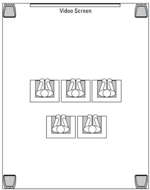
PLACING FOUR SUBWOOFERS
When installing four subwoofers, place each one in a room corner. In rooms with more than four corners, use the four corners closest to the listening area.
PLACING TWO SUBWOOFERS
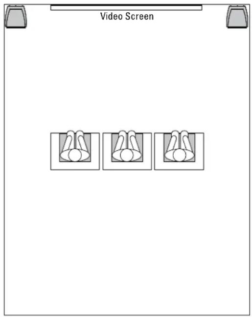
Placement of two subwoofers will be determined by your room's seating arrangement.
Rooms with a single row of seating
Placing the subwoofers in the two front corners will produce the most consistent bass performance throughout a single row of seating.
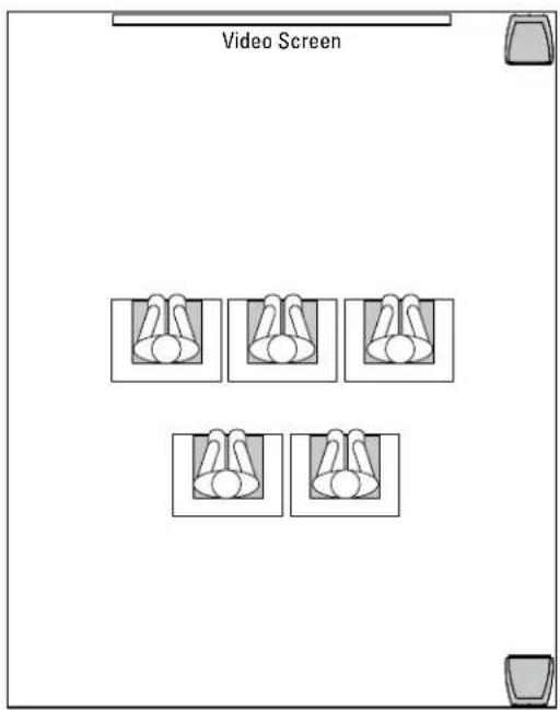
Rooms with multiple seating rows
Placing one subwoofer in a front corner and the other subwoofer in the rear corner on the same side will produce the most consistent bass performance throughout multiple seating rows.
PLACING A SINGLE SUBWOOFER
When installing a single subwoofer, be prepared to experiment with different locations to find the one that produces the best results throughout your room's seating area. As in the previous examples, placing the subwoofer in a corner will produce the fewest number of deep response dips, which cannot be corrected with equalization.
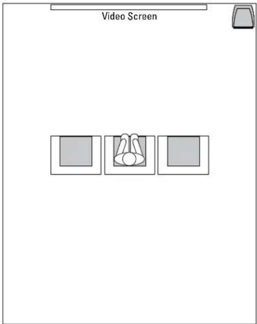
Since listening and speaker locations are equally important, the trial-and-error process can be time-consuming. However, the sonic rewards are well worth the time spent determining the ideal placement locations. Remember that peaks (below the subwoofer crossover frequency) can be minimized or eliminated by the proper adjustment of the Concerta B1's Equalization controls, but dips cannot be corrected via equalization. Therefore, the most important objective is to find locations that result in the minimum number (and severity) of dips. Contact your authorized Revel dealer for assistance in determining the proper placement of your Revel loudspeakers and subwoofers.
After placing the B1 subwoofer(s), begin playback of a familiar music or film source that has substantial bass content. Listen from the primary listening position, increasing the overall volume of the system to a comfortable level. Adjust the Subwoofer Level (volume) control until you obtain the desired blend of bass. Also, test the subwoofer level by playing a recording of a deep male voice. Setting the subwoofer level (or crossover frequency) too high results in unnaturally "thick" or "boomy" vocal reproduction. Bass response should not overpower the room, and should be adjusted to achieve a harmonious blend across the entire audible range.
If you are using a multichannel receiver or processor with a subwoofer output, it's preferable to use the Subwoofer Level adjustment on the processor. Set the B1 Level control to the indicated "Nominal" position.
NOTE: Setting the level of the subwoofer in relation to the left and right front speakers is of critical importance because it is essential that the subwoofer integrate smoothly with the entire system. Setting the level too high results in an overpowering bass response. Setting the level too low negates the benefits of the B1 subwoofer.
MAKING CONNECTIONS
CAUTION: Never make or break connections unless all system components are powered off.
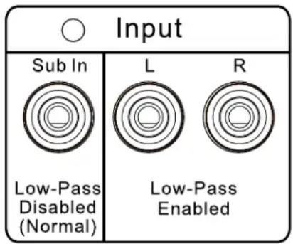
Figure 8: Rear-panel input connectors
This section provides typical examples of cable connections with different system configurations and devices. Review the owner's manuals for associated audio components to determine their connection requirements.
The B1 subwoofer input connectors are located on the rear panel. Two gold-plated RCA connector options are available – Sub In Low-Pass Disabled (Normal) and L/R Low-Pass Enabled – as shown in Figure 8.
In most cases, you'll use the Sub In connector, as it's designed for multichannel use. This input bypasses the low-pass filter, and is the appropriate input for most installations. This connector should be used when there is a dedicated subwoofer output available on the audio processor or receiver.
Some processors incorrectly label the subwoofer output as LFE; others offer both an LFE and a Subwoofer output. If there is no labeled subwoofer output, use the LFE output. If the output has labeled connections for both LFE and Subwoofer, use the Subwoofer output.
The L (Left) and R (Right) connectors on the rear panel of the B1 are for use with 2-channel applications, where there is no dedicated subwoofer output available. These inputs are automatically crossed-over by the adjustable Low-Pass Crossover control on the rear panel. Having the low-pass filter enabled helps offset the fact that most 2-channel systems do not perform any high-pass filtering on the main speakers, minimizing the advantages of using a subwoofer. These connectors should be used in 2-channel applications where the receiver or preamplifier lacks a dedicated subwoofer or LFE output.
NOTE: The Concerta B1 subwoofer has a third connection option – wireless connection is also available when coupled with the optional TX1 transmitter. Refer to the "Wireless Connection" section found later in this manual for additional details regarding this option.
MULTICHANNEL APPLICATIONS – TYPICAL CONNECTION
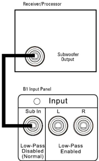
Figure 9: Typical connection
This configuration is for use with multichannel processors or receivers that have a single dedicated Subwoofer or LFE output connector.
Connect an RCA patch cable from the Subwoofer or LFE output on the processor/receiver to the Sub In connector on the B1 rear panel, as shown in Figure 9.
2-CHANNEL APPLICATIONS – CONNECTING TO THE MAIN OUTPUTS
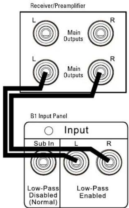
Figure 10: Connection to main outputs
This configuration is for use with 2-channel preamplifier/power amplifier combinations or 2-channel receivers that have full-range outputs for the left and right channels. The internal low-pass filter in the B1 is used to limit frequency range of the subwoofer, preventing undesirable overlap with the main loudspeakers.
- Connect an RCA patch cable between the left main output on the receiver/preamplifier to the L(eft) Low-Pass Enabled connector on the B1 rear panel, as shown in Figure 10.
- Connect an RCA patch cable between the right main output on the receiver/preamplifier to the R(right) Low-Pass Enabled connector on the B1 rear panel.
NOTE: This configuration applies to receivers with preamplifier outputs or to preamplifier/power amplifier configurations in which there are two sets of Main outputs. If the receiver has jumpers from the Pre- or Main-Out to the Amp in connectors or if the preamplifier has only one set of Main-Out connectors, a
Y-adapter should be used to send the same signal to both the main power amplifier and the subwoofer(s). Tape Out or Record Out connectors cannot be used.
MULTICHANNEL APPLICATIONS – MULTIPLE SUBWOOFER CONNECTIONS
flowchart
graph TD
    A["Receiver/Processor"] --> B["Subwoofer Output"]
    B --> C["Input"]
    C --> D["B1 Input Panel Sub 1"]
    C --> E["B1 Input Panel Sub 2"]
    style A fill:#f9f,stroke:#333
    style C fill:#ccf,stroke:#333
    style D fill:#cfc,stroke:#333
    style E fill:#cfc,stroke:#333
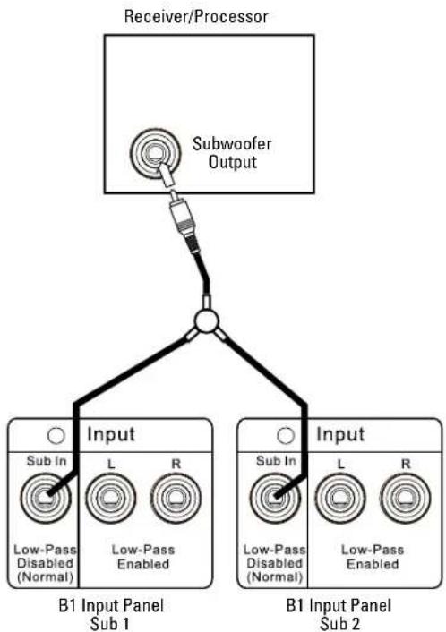
Figure 11: Connection to multiple B1 subwoofers
This configuration is for use with multiple B1 subwoofers and a multichannel processor or receiver.
NOTE: The supplied single-RCA patch cord can be used in any of the three connections described below, but you will need to purchase an RCA Y-adapter and possibly an additional single-RCA cable.
- Connect an RCA patch cable from the Subwoofer or LFE output on the processor/receiver to the single input on the Y-adapter, as shown in Figure 11.
- Connect an RCA patch cable from one of the outputs of the Y-adapter to the Sub In connector on the first B1 rear panel.
- Connect an RCA patch cable from the second output of the Y-adapter to the Sub In connector on the second B1 rear panel.
MULTICHANNEL APPLICATIONS – MULTIPLE SUBWOOFER OUTPUTS WITH A SINGLE SUBWOOFER
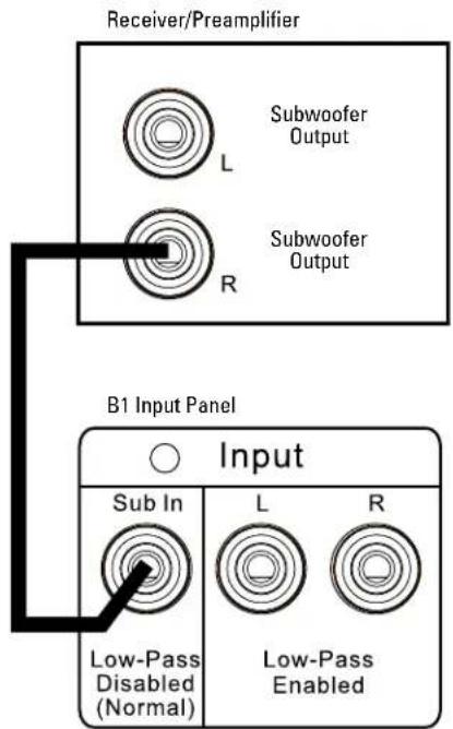
Figure 12: Typical connection with multiple subwoofer outputs
This configuration is for use with multichannel processors or receivers that have more than one dedicated Subwoofer or LFE output connector.
- Set the processor or receiver to "Mono Subwoofer."
- Connect the supplied RCA patch cable from one of the Subwoofer or LFE outputs on the processor/receiver to the Sub In connector on the B1 rear panel, as shown in Figure 12.
MULTICHANNEL APPLICATIONS – MULTIPLE SUBWOOFER OUTPUTS AND MULTIPLE SUBWOOFERS
flowchart
graph TD
    A["Receiver/Processor"] --> B["Input"]
    B --> C["B1 Input Panel Sub 1"]
    B --> D["B1 Input Panel Sub 2"]
    subgraph B1 Input Panel Sub 1
        E["Sub In: Low-Pass Disabled (Normal)"]
        F["Input L: Subwoofer Output"]
        G["Input R: Subwoofer Output"]
    end
    subgraph B1 Input Panel Sub 2
        H["Input L: Sub In, Input R: Low-Pass Disabled (Normal)"]
        I["Input R: Sub In, Input L: Low-Pass Disabled"]
    end
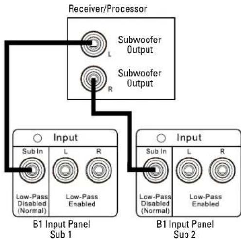
Figure 13: Multiple subwoofer connections
This configuration is for use with multiple B1 subwoofers and a multichannel processor or receiver that has more than one dedicated Subwoofer or LFE output connector.
- Set the processor or receiver to "Mono Subwoofer."
- Connect the supplied RCA patch cable from one of the Subwoofer or LFE outputs on the processor/receiver to the Sub In connector on the first B1 rear panel, as shown in Figure 13.
- Connect the RCA patch cable that was supplied with the second B1, from the second Subwoofer or LFE output on the processor/receiver to the Sub In connector on the second B1 rear panel.
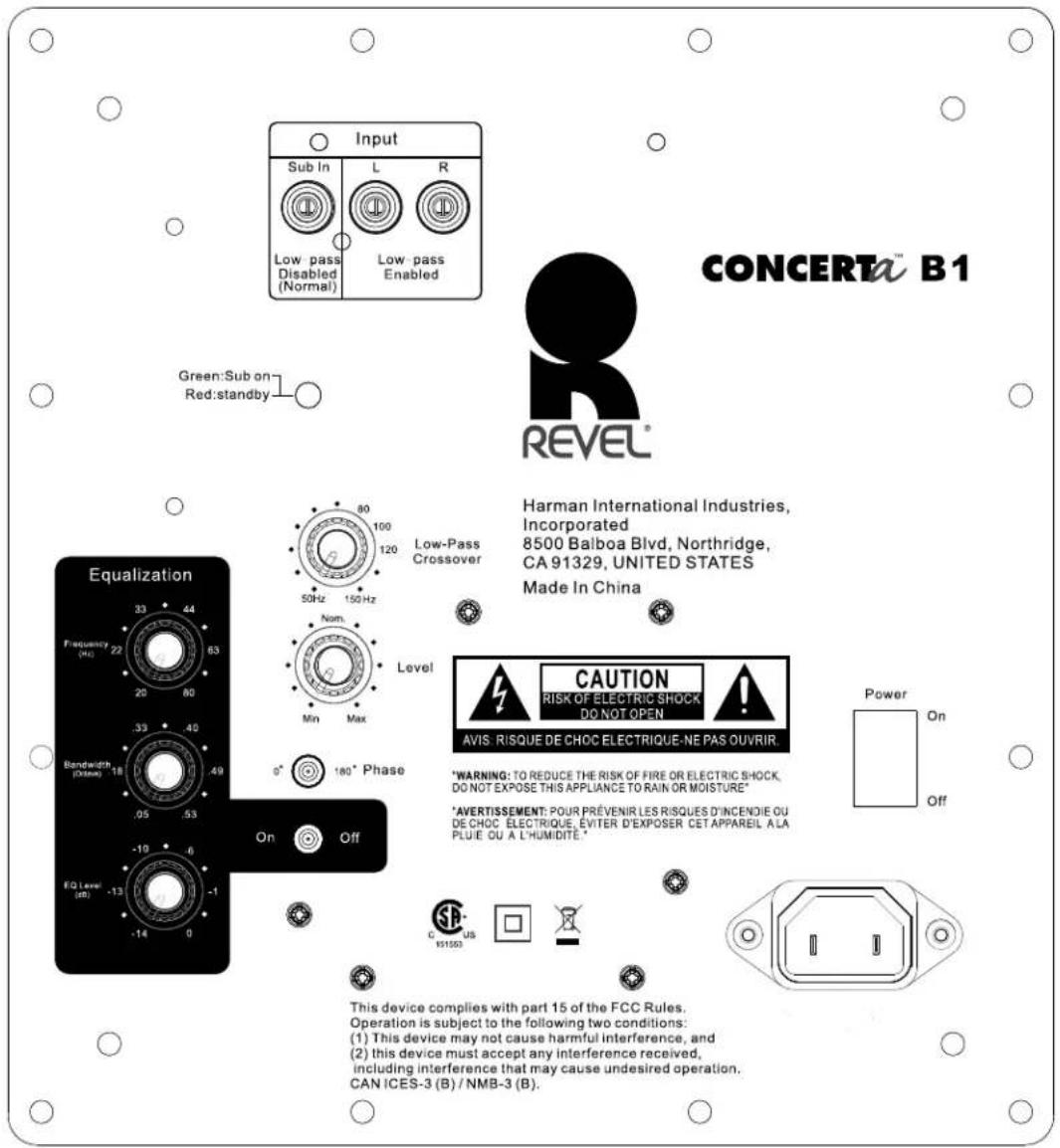
Figure 14: Rear-panel controls and connectors
SUBWOOFER OPERATION
The rear panel of the Concerta B1 subwoofer, shown in Figure 14, contains all of the available connectors and controls. The Input section of the rear panel was discussed in the "Making Connections" section, earlier in this manual. The subwoofer controls are discussed in this section. For more information on the wireless connection option, refer to the "Wireless Connection" section found later in this manual.
POWER INDICATOR LED
The Power Indicator LED identifies the current state of the B1 subwoofer. The subwoofer has three different powered states — each identified by a different color. The Power Indicator LED reflects the color of the current power state. The color and the state each color indicates are:
Red: Standby – the B1 automatically enters Standby if no signal is detected from the system for 10 minutes.
Green: On – as soon as a signal is detected, the B1 powers on.
SUBWOOFER LEVEL (VOLUME) CONTROL
Provides basic volume adjustment for the subwoofer. Begin with this control set to the nominal "12 o'clock" position.
LOW-PASS FREQUENCY CONTROL
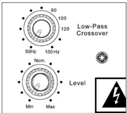
Figure 15: Rear-panel controls and connectors
Adjusts the variable 50Hz – 150Hz low-pass crossover, which determines the highest frequency at which the B1 reproduces sounds. Set the crossover to a lower frequency setting, between 50Hz and 100Hz, when using larger main loudspeakers that can comfortably reproduce some low-frequency sound.
With a lower frequency setting, the B1 subwoofer concentrates on reproducing the deep bass required by contemporary music and film soundtracks. Set the crossover to a higher frequency, between 100Hz and 150Hz, for smaller bookshelf loudspeakers that do not extend to the lower bass frequencies.
If the frequency control is set too high, the bass sounds "boomy" and can overpower the overall sound of the listening room. If the frequency control is set too low, some low frequency sound may be difficult to hear, or may be absent altogether.
This control has no effect when using the Sub In input or if the Low-Pass Switch, shown in Figure 17, is set to Off (Normal) because in both cases the receiver/processor sets the crossover frequency.
NOTE: This control does not limit the frequency range of the main speakers in the system. The objective of adjusting the Low-Pass Frequency control is to ensure that all frequencies are reproduced while minimizing any overlap between the subwoofers and the main speakers. Having both the subwoofer and main speakers reproduce the same frequencies should be avoided, as it results in very irregular response, since some frequencies are reinforced when they happen to be in phase while others are canceled because they are out of phase.
PHASE SWITCH
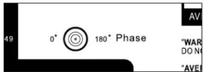
Figure 16: Phase switch
Compensates for the absolute phase of the subwoofer's output relative to the front speakers. Some associated electronics can invert the absolute phase. Use this switch to correct such occurrences. Proper phase adjustment can also depend on variables such as subwoofer placement and listener position. Use this switch, shown in Figure 16, to maximize bass output at the primary listening position.
- Select the 0° setting to set the B1 acoustic output in phase (0 degrees) with the input.
- Select the 180° setting to invert the B1 acoustic output (180 degrees) relative to the input.
EQUALIZATION CONTROLS
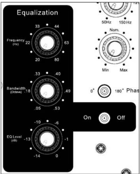
Figure 18: Equalization controls
Optimizes the subwoofer's response for your specific listening room. The parametric equalizer includes variable controls to adjust Frequency, Bandwidth and Level, as shown in Figure 18.
NOTE: Specific measurement equipment is required to properly adjust the Equalization controls. Your authorized Revel dealer can make the appropriate measurements, using suitable equipment to ensure optimal results.
POWER SWITCH
Connects or disconnects power from the AC input cord. During periods of intermittent use, the Power Switch can be left on. Turn off the Power Switch for extended periods of nonuse.
AC INPUT CORD
Provides power to the B1 through the power cord.
ROUTINE CARE & MAINTENANCE
The B1 cabinet's finish does not require routine maintenance. However, cabinet surfaces that have been marked with fingerprints, dust or other dirt can be cleaned using a soft cloth. Do not use any cleaning products or polishes on the cabinet or grille.
SPECIFICATIONS
B1 SUBWOOFER
| Frequency Response +/-0.5dB in the pass-band | |
| Low Frequency -3dB at 36Hz | |
| Extension (Anechoic) -6dB at 32Hz-10dB at 29Hz | |
| Maximum Amplifier Output 20Hz - 150Hz with no more than0.1% THD, 250W RMS, 300 dynamic | |
| Low-Pass Crossover Frequencies | 50Hz - 150Hz, 24dB/octave,continuously variable |
| Power Requirements 120V - 60Hz, 2AMP220 - 240V -50/60Hz AMP | |
| Height 17-3/4" (45.0cm), including feet | |
| Width 15-3/4" (40.0cm) | |
| Depth 14" (35.6cm) with grille | |
| Weight 51 lb (23.15kg) | |
Features, specifications and appearance are subject to change without notice.
WARRANTY
Revel Series speakers are warranted against defects. The duration of the speaker's warranty depends on the laws in the country in which it was purchased. Your local Revel retailer can help you determine the length of your warranty.
HARMAN
HARMAN International Industries, Incorporated
8500 Balboa Boulevard, Northridge, CA 91329 USA
© 2014 HARMAN International Industries, Incorporated. All rights reserved.
Revel and the Revel logo are trademarks of HARMAN International Industries, Incorporated, registered in the United States and/or other countries.
Nomex is a registered trademark of E. I. du Pont de Nemours and Company.
Features, specifications and appearance are subject to change without notice.
For questions, assistance or additional information concerning any of our products,
call us at: (888) 691-4171. For technical support, submit your detailed inquiry to: csupport@harman.com.
Part No. 950-0507-001 Rev: A

REVEL
by HARMAN
www.revelspeakers.com
- IMPORTANT SAFETY PRECAUTIONS READ FIRST!
- ABOUT THE REVEL® CONCERTA™ B1 SUBWOOFER
- B1 HIGHLIGHTS
- SUBWOOFER PLACEMENT
- SUBWOOFER PLACEMENT CONSIDERATIONS
- PLACING FOUR SUBWOOFERS
- PLACING TWO SUBWOOFERS
- Rooms with a single row of seating
- Rooms with multiple seating rows
- PLACING A SINGLE SUBWOOFER
- MAKING CONNECTIONS
- MULTICHANNEL APPLICATIONS – MULTIPLE SUBWOOFER OUTPUTS WITH A SINGLE SUBWOOFER
- MULTICHANNEL APPLICATIONS – MULTIPLE SUBWOOFER OUTPUTS AND MULTIPLE SUBWOOFERS
- SUBWOOFER OPERATION
- POWER INDICATOR LED
- SUBWOOFER LEVEL (VOLUME) CONTROL
- LOW-PASS FREQUENCY CONTROL
- PHASE SWITCH
- POWER SWITCH
- AC INPUT CORD
- ROUTINE CARE & MAINTENANCE
- SPECIFICATIONS
- WARRANTY
- HARMAN
Brand : Revel
Model : Concerta B1
Category : Subwoofer