
DLV8315-4J300F0 - Thin client Advantech - Free user manual and instructions
Find the device manual for free DLV8315-4J300F0 Advantech in PDF.


| Product Type | Thin Client |
| Brand | Advantech |
| Model | DLV8315-4J300F0 |
| Processor | Intel Celeron J6412 Quad-Core |
| Memory | 8 GB DDR4 (soldered) |
| Storage | 64 GB eMMC |
| Operating System | Windows 10 IoT Enterprise or Linux (optional) |
| Dimensions (W x D x H) | 200 x 130 x 30 mm |
| Weight | 1.2 kg |
| Power Supply | 12V DC, 3.33A (40W adapter included) |
| Power Consumption | Typical 15W, max 25W |
| Cooling | Fanless design |
| Video Output | 1x HDMI 2.0, 1x DisplayPort 1.2 |
| USB Ports | 4x USB 3.2 Gen 1 Type-A |
| Networking | 1x Gigabit Ethernet (RJ45) |
| Wireless | Wi-Fi 6 (802.11ax) + Bluetooth 5.2 |
| Expansion | 1x M.2 2280 Key M (PCIe Gen3 x2) |
| Audio | 1x combo headset jack, built-in speaker |
| Security | TPM 2.0, Kensington lock slot |
| Mounting | VESA mount (75x75 mm) |
| Operating Temperature | 0°C to 45°C |
| Certifications | CE, FCC Class B |
| Warranty | 3 years limited |
Frequently Asked Questions - DLV8315-4J300F0 Advantech
User questions about DLV8315-4J300F0 Advantech
0 question about this device. Answer the ones you know or ask your own.
Ask a new question about this device
Download the instructions for your Thin client in PDF format for free! Find your manual DLV8315-4J300F0 - Advantech and take your electronic device back in hand. On this page are published all the documents necessary for the use of your device. DLV8315-4J300F0 by Advantech.
USER MANUAL DLV8315-4J300F0 Advantech
natural_image
Simple line drawing of a rectangular device with a handle and top panel (no text or symbols)ADVANTECH
DLOG
DLT-V83 Series Industrial Computer
Safety Instructions / Quick Start and Installation (EN) Sicherheitshinweise / Quick Start und Installation (DE)
安全 / 快速入门和安装 (CN)
ADVANTECH
Enabling an Intelligent Planet
DLT-V83
EN: Startup Manual – Content Overview
For safe and proper use, follow these instructions.
Keep them for future reference.
WICHTIG:
Copyright / Technical support and assistance
Safety Instructions
Introduction / Intended use / Requirement for commissioning and operating personell / Battery pack safety / Radiation emission / Information on safe mounting / Information on safe electrical installation / Safety during ongoing work operations / Regular maintenance work / Repairs and modifications / Recycling / Regulatory information
Quick Start and Installation
Packing list / Overview of important operating elements / External connectors / Configuration (Front keys, radio) / Notes on the mechanical mounting / Notes on the electrical installation / Connect cables, seal cable passages / Attaching the cable cover
Regional Service & Customization Centers
China: Kunshan 86-512-5777-5666 Taiwan: Taipei 886-2-2792-7818
Netherlands: Eindhoven 31-40-267-7000 Poland: Warsaw 00800-2426-8080
USA: Milpitas, CA 1-408-519-3898
Worldwide Offices
Greater China
China
Toll Free 800-810-0345
Beijing 86-10-6298-4346
Shanghai 86-21-3632-1616
Shenzhen 86-755-8212-4222
Chengdu 86-28-8545-0198
Hong Kong 852-2720-5118
Taiwan
Toll Free 0800-777-111
Taipei & IoT
Campus 886-2-2792-7818
Taichung 886-4-2329-0371
Kaohsiung 886-7-229-3600
Middle East and Africa
Israel 072-2410527
Asia
Japan
Toll Free 0800-500-1055
Tokyo 81-3-6802-1021
Osaka 81-6-6267-1887
Nagoya 81-0800-500-1055
Korea
Toll Free 080-363-9494
Seoul 82-2-3663-9494
Singapore
Singapore 65-6442-1000
Malaysia
Kuala Lumpur 60-3-7725-4188
Penang 60-4-537-9188
Thailand
Bangkok 66-02-2488306-9
Vietnam
Hanoi 84-24-3399-1155
India
Bangalore 91-80-2545-0206
Pune 91-94-2260-2349
Indonesia
Jakarta 62-21-751-1939
Australia
Toll Free 1300-308-531
Melbourne 61-3-9797-0100
Europe
Germany
Toll Free 00800-2426-8080/81
Munich 49-89-12599-0
Düsseldorf 49-2103-97-855-0
France
Paris 33-1-4119-4666
Italy
Milano 39-02-9544-961
Benelux & Nordics
Breda 31-76-523-3100
UK
Newcastle 44-0-191-262-4844
London 44-0-870-493-1433
Poland
Warsaw 48-22-31-51-100
Russia
Moscow 8-800-555-01-50
St. Petersburg 8-800-555-81-20
Czech Republic
Ústí nad Orlicí
420-465-521-020
Ireland
Oranmore 353-91-792444
Americas
North America
Toll Free 1-888-576-9668
Cincinnati 1-513-742-8895
Milpitas 1-408-519-3898
Irvine 1-949-420-2500
Ottawa 1-815-434-8731
Brazil
Toll Free 0800-770-5355
São Paulo 55-11-5592-5367
Mexico
Toll Free 1-800-467-2415
Mexico City 52-55-6275-2727
DLT-V83 Startup Manual
P/N 20080V8301
English (EN): Important information
Copyright
This document and the software and hardware included with this product are copyrighted 2019 by Advantech Co., Ltd. All rights are reserved.
This document is intended for reference purposes only. All product specifications are subject to change without notice.
Advantech Co., Ltd. reserves the right to make improvements in this document in the products described in this document at any time without notice
No part of this document may be reproduced in any form or by any means, electronic, photocopying, recording, translating, transmitting or otherwise, without prior written permission of Advantech Co., Ltd.
Information provided in this document is intended to be accurate and reliable.
However, Advantech Co., Ltd. assumes no responsibility for its use, nor for any infringements of the rights of third parties, which may result from its use.
Advantech Co., Ltd. assumes no liability for technical inaccuracies, typographic errors or faults in this documentation. Advantech Co., Ltd. also assumes no liability for damages caused directly or indirectly by the delivery, performance or usage of this material.
Note regarding all links and website content included in this document:
Advantech Co., Ltd. is not responsible for the accessibility of the websites and for the content of external links contained in this document. The content and accessibility of the linked websites are the sole responsibility of their operators.
Acknowledgements
The software and hardware designations as well as the brand names used in this documentation are in most cases also registered trademarks and are subject to the international law (trademark, brand and patent-protection laws). All product names or trademarks are properties of their respective owners.
Manufacturer address
Advantech Co., Ltd.
No. 1, Alley 20, Lane 26, Rueiguang Road,
Neihu District, Taipei 11491, Taiwan, R.O.C.
Technical support and assistance
Contact your distributor, sales representative, or an Advantech Service Center for technical support.
Please have the following information ready:
- Product name
- Serial number
– Description of your peripheral attachments
— Description of your software (operating system, application software, etc.)
— A complete description of the problem
— The exact wording of any error messages
Find the contact data of our Global Advantech Service Centers on our website:
http://erma.advantech.com
DLT-V83 Industrial Computer Safety Instructions (EN)

IMPORTANT:
For safe and proper use, follow these safety instructions.
Keep them for future reference.
1 INTRODUCTION

WARNING
Important for your safety.
These safety instructions apply to all models in the DLT-V83 Series: For DLT-V8310, DLT-V8312 and DLT-V8315 in various equipment levels.
Non-observance of the safety instructions can result in injury to persons and in physical damage, e.g. due to incorrect commissioning procedures or due to maintenance work not being completed.
The manufacturer accepts no liability for damage resulting from a failure to comply with this information.
- Read and observe these safety instructions before commissioning and using the DLT-V83. This protects you and other persons and prevents damage to the equipment and to technical equipment in the surrounding environment.
- Observe all other documents included with the device.
- Retain all documents and pass them on to any future owners of the equipment.
- Read and observe the "DLT-V83 Operating Instructions" available online and provided for download from our websites
www.advantech.com
www.advantech-service-iot.eu
On our websites you will also find the latest versions of all DLT-V83 documentation.
2 INTENDED USE
DLT-V83 Industrial Computers are data communication terminals for use in commercial industries such as logistics, warehousing and manufacturing. Any other or additional use beyond this is regarded as improper use.
DLT-V83 Industrial Computers are only permitted to be operated:
– In accordance with the defined intended use.
– Within the usage limits and in accordance with the technical data.
- Observing the information in the documentation and in particular the safety and warning notices.
DLT-V83 Industrial Computers:
- Are not approved for use in explosion-hazard areas.
- Are not approved for use on ships and on rail vehicles.
- Are not approved for use in life-support systems or critical safety systems where system malfunction can lead to the direct or indirect hazard of human life.
DLT-V83 Industrial Computers were designed and built according to modern technology and accepted safety regulations. Improper use can result in injury to persons and in property damage, however, necessitating the following:
– Correct transport, storage, commissioning and maintenance as specified
– Operation by trained personnel
The owner/operator commitments with regards to safety (accident prevention regulations, occupational safety) must be observed.
3 REQUIREMENT FOR COMMISSIONING AND OPERATING PERSONNEL
Commissioning and maintenance
Work such as commissioning and maintaining the DLT-V83 is only permitted to be performed by skilled personnel who have specialist vocational training and who have up-to-date knowledge and experience in the area of work in question.
Examples:
- Mechanical mounting work must be performed by skilled mechanical personnel.
If the DLT-V83 is incorrectly mounted onto vehicles, for example, this can result in serious accidents.
— Electronic work on the DLT-V83 must be performed by skilled electronics personnel; there is a risk of electric shock when connecting to the power supply, for example.
— For the DLT-V83 with integrated uninterrupted power supply (UPS), specialist knowledge on the handling of lithium-ion battery packs is required.
The “DLT-V83 Operating Instructions” (available online) offer comprehensive information on commissioning the device, in particular also for use on vehicles.
Requirements for the operating personnel
Users of the DLT-V83 must be trained by skilled personnel and instructed in the operation of the device. All users must be familiar with all functions of the product they come into contact with.
4 BATTERY PACK SAFETY
EXPLOSION HAZARD! BATTERY PACK SAFETY NOTICE.
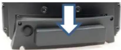
DLT-V83 devices with integrated uninterrupted power supply (UPS) contain lithium-ion battery packs in the cable cover on the device.
natural_image
Close-up of a black plastic mechanical component with a blue arrow pointing to a button or latch (no text or symbols visible)Battery packs may ignite if stored or handled incorrectly (fire risk, explosion risk), and may cause chemical burns or release poisonous substances.
- Handle the DLT-V83 and the integrated battery pack with care, and do not allow it to become damaged, to fall or be dropped, or be short-circuited.
- Do not tamper with, disassemble or repair the battery packs.
- Observe the specified temperature range, both during storage and in the work environment.
— Do not utilize the device near sources of heat or fire, open flames or heaters. - Do not allow water or other liquids to come into contact with the device (exercise particular caution with corrosive liquids).
- Suitable fire extinguishers must be provided in line with safety regulations.
- If battery packs become damaged, caustic electrolyte liquid may leak out. This liquid must not under any circumstances be permitted to come into contact with eyes, skin or clothing. On contact with eyes or skin, rinse immediately with clear, running water and consult a doctor.
THERE IS A RISK OF EXPLOSION IF THE BATTERY PACK IS SWAPPED OUT AND REPLACED WITH AN INCORRECT/NON-APPROVED BATTERY PACK.
This also applies to the real time clock battery installed in the DLT-V83.
Do not open the DLT-V83, and do not replace the RTC battery. EXPLOSION HAZARD.
Prevent physical damage due to deep discharge.
Storing the battery packs incorrectly will cause them to discharge completely (deep discharge) and thus damage them irreparably.
— Place the DLT-V83 into operation within 3 (three) months after receiving it.
— Charge the integrated battery packs by connecting the DLT-V83 to the power supply.
- If you are not placing the DLT-V83 into operation within 6 (six) months, make sure you charge it intermediately.
5 RADIATION EMISSION
Only applies to devices with radio equipment: Danger of radiation emission.
DLT-V83 devices with radio equipment emit high frequency energy (abbreviation: HF).
To protect persons and domestic animals against HF radiation:
- Mount the DLT-V83 so that persons and domestic animals maintain a minimum distance of 20 to 50~cm from the radio antennas.
— Ensure that persons observe this minimum distance when operating the DLT-V83. - High frequency energy can interfere with technical devices. For this reason, do not use the DLT-V83 in the vicinity of pacemakers or other medical devices.
- Only operate the DLT-V83 with radio equipment that are approved by the manufacturer for this device.
- Make sure that the transmission power and the radio frequency of the DLT-V83 comply with the regulations for the respective country where the device is deployed.
- Observe all applicable regulations for your deployment location/country with regard to operating channels, radio frequencies and the maximum permissible transmitting power. Responsibility for this lies with the company operating the DLT-V83. The regulatory authorities in the relevant country can provide information on this.
Any modifications to the DLT-V83 radio equipment which are not expressly approved by the party responsible for the compliance can lead to the withdrawal of the operating license for this device.
6 INFORMATION ON SAFE MOUNTING
During the mounting process
The DLT-V83 can fall down and cause injuries due to its weight.
- Use the assistance of a second person for installation work.
- Always hold the DLT-V83 by the housing with both hands.
- Never use the antenna cap as a handle as it may break due to the weight involved.
The strain relief rail of the DLT-V83 can have sharp edges and cause cutting injuries.
- Do not hold the DLT-V83 by the strain relief plate.
Choosing the mounting position and installation environment
- The installation height of the DLT-V83 device shall not exceed 2 m.
- The ergonomic operability of the DLT-V83 should be taken into account when selecting the mounting position.
- Mount the DLT-V83 in such a way that no persons can be injured if the device mounting should break (e.g. as a result of a fatigue fracture).
- Otherwise, it is essential to adopt corresponding safety measures.
- Ensure that the installation environment is correct, as is not permitted to result in an enclosed system because the cooling concept of the DLT-V83 requires a fresh air supply. Without a supply of fresh cooling air, the DLT-V83 may overheat and may be damaged beyond repair.
Specific information on vehicle mounting (forklifts, etc.)
- Mount the DLT-V83 so that the driver's field of view remains clear and safe driving operation is guaranteed.
– During the mounting process, observe the requirements of the vehicle manufacturer relating to attaching auxiliary devices and connecting auxiliary consumers. - Observe all requirements relating to welding or drilling on support components of the vehicle.
- Observe the more detailed information on the mounting process given in the "DLT-V83 Operating Instructions" available online, for example on the potential conditions on vehicles, requirements for electrically isolated mounting, etc.
7 INFORMATION ON SAFE ELECTRICAL INSTALLATION
Danger of electric shock
— Do not put the DLT-V83 into operation if it is showing damage.
— Do not open or modify the DLT-V83.
- If the DLT-V83 with AC power supply unit is opened while it is connected to the power supply, there is a danger of death due to electric shock!
- Only connect or disconnect electrical connections when the device is in a de-energized state.
- Use only original Advantech power supply cables; these meet the specific requirements for low-temperature flexibility, UV resistance, oil resistance, etc.
Installing the disconnecting device
The DLT-V83 is not equipped with disconnecting devices that are accessible from the outside; it does not have switches.
- To allow the device to be quickly disconnected from the power supply in emergency situations, install an easily accessible disconnecting device close to the device and ensure that the disconnecting device isolates all supply lines.
Power supply unit fuse blows repeatedly
If the fuse of the integrated power supply units blows again immediately after replacement, there is a danger of electrical shock:
— Send in the DLT-V83 immediately for repair.
DLT-V83 with DC power supply unit
- Only connect devices with DC power supply unit to Safety Extra Low Voltage (SELV) circuits.
— The DC+ connecting cable must be protected by a fuse (30 AT max.). - The ignition connecting cable must be protected by a fuse of the following type: 5x20 mm T 125 mA L / 250 V, for example, a Wickmann 195-125 mA / 250 V.
8 SAFETY DURING ONGOING WORK OPERATIONS
Requirements for the operating personnel
Users of the DLT-V83 must be trained by skilled personnel and instructed in the operation of the device. All users must be familiar with all functions of the product they come into contact with.
General
- Do not use the DLT-V83 in explosion hazard areas.
- Switch off the DLT-V83 if located in the vicinity of petrol stations, fuel depots, chemical plants, etc.
- Switch off the DLT-V83 before using the interfaces underneath the antenna.
The following applies when using the DLT-V83 on vehicles:
- The vehicle driver is not permitted to operate the DLT-V83 while driving. Operating the device can represent a distraction from driving operations and there is an increased risk of accident.
- The DLT-V83 must be disconnected from the vehicle battery while the vehicle battery is being charged. Or it must be ensured that the maximum permitted input voltage of the DLT-V83 is not exceeded.
9 REGULAR MAINTENANCE WORK
General
To avoid damage to the DLT-V83 and to ensure safe functioning:
- Depending on the load and environmental conditions, check at least once per month, and more often if necessary, that all connected cables are secured and that the cable cover is tightly sealed (important for IP protection against dust, etc.).
Cleaning the device
There is a danger of electric shock if live parts of the DLT-V83 are touched during cleaning.
- Switch off the DLT-V83 before cleaning.
— Disconnect from the power supply. - Disconnect connected accessories.
– Clean the touchscreen and housing with a damp cloth and a neutral glass cleaning agent. - Do not use any chemicals such as benzene, thinner or acidic/alkaline solutions for cleaning.
— Do not use any compressed air or high-pressure cleaning equipment.
Devices used in vehicles
DLT-V83 devices used in vehicles are subject to high loads due to vibration and shocks. To ensure the secure fastening of the device to the vehicle, the following points must be checked at least once a month, and where necessary more often, depending on the load and environmental conditions:
- Check that the DLT-V83 is securely positioned in the corresponding mount (e.g. in the RAM mount or in the mounting bracket).
— Check that all fastening elements are correctly secured (e.g. screws, etc.).
— Check that the mounting with the DLT-V83 is securely fastened to the vehicle.
10 REPAIRS AND MODIFICATIONS
Only authorized Advantech Service Centers may perform the following:
- Open the device (front unit and base unit)
- Repairs
- Modifications
– Replace integrated modules, e.g. radio cards
The device operator may perform the following (only qualified skilled personnel):
- Open and close the antenna cap (e.g. for replacing CFast card and SIM card)
- Open and close the cable cover
The legal warranty shall apply. It expires if the customer performs measures on the device that are only permitted to be performed by Advantech Service Centers.
Accessories and peripherals
Accessories and peripherals may only be installed or integrated if expressly approved by Advantech for the respective DLT-V83. If other parts are attached or installed and connected, claims for warranty and / or product liability will be lost.
If the battery pack in the cable cover is faulty, the entire cable cover, including the integrated battery packs, must be replaced.
THERE IS A RISK OF EXPLOSION IF THE BATTERY PACK IS SWAPPED OUT AND REPLACED WITH AN INCORRECT/NON-APPROVED BATTERY PACK.
11 RECYCLING
Waste electrical equipment and battery packs that are no longer being used may not be disposed of in the regular residential or domestic waste; they must be taken to an official public collection point and handled by a disposal provider.
Please contact the responsible authorities in your country/region to find out about the applicable regulations for proper disposal, if necessary.
12 REGULATORY INFORMATION
You can find regulatory information in the "DLT-V83 Operating Instructions". Please observe the device labels on the rear side of the DLT-V83 (FCC-ID information, etc.).
DLT-V83 Industrial Computer Quick Start and Installation (EN)
These Quick Start and Installation Instructions apply to all models in the DLT-V83 series: For DLT-V8310, DLT-V8312 and DLT-V8315 in various equipment levels.

IMPORTANT:
- Read and observe these instructions before commissioning and using the DLT-V83.
- Read and observe the "DLT-V83 Safety Instructions".
— Observe all other documents included with the device. - Retain all documents and pass them on to any future owners of the equipment.
- Read and observe the "DLT-V83 Operating Instructions" available online and provided for download from our websites:
www.advantech.com
www.advantech-service-iot.eu
On these websites you will also find the latest versions of all DLT-V83 documentation.
1 PACKING LIST
Before setting up the system, check that the items listed below are included and in good condition. If any item does not accord with the table, please contact your dealer immediately:
– DLT-V83 Industrial Computer
— Power cable (DC or AC variant)
– Cable cover (with or without integrated UPS battery pack)
— Cable sealing set including cable clips, grommets and fastening screws
- Product supplement like these instructions and possibly "OS End User License Agreement" (depends on optional OS type)
2 OVERVIEW OF IMPORTANT OPERATING ELEMENTS
NOTICE: Property damage
Users of the DLT-V83 must be trained by skilled personnel and instructed about the operation of the device.
2.1 Rear side
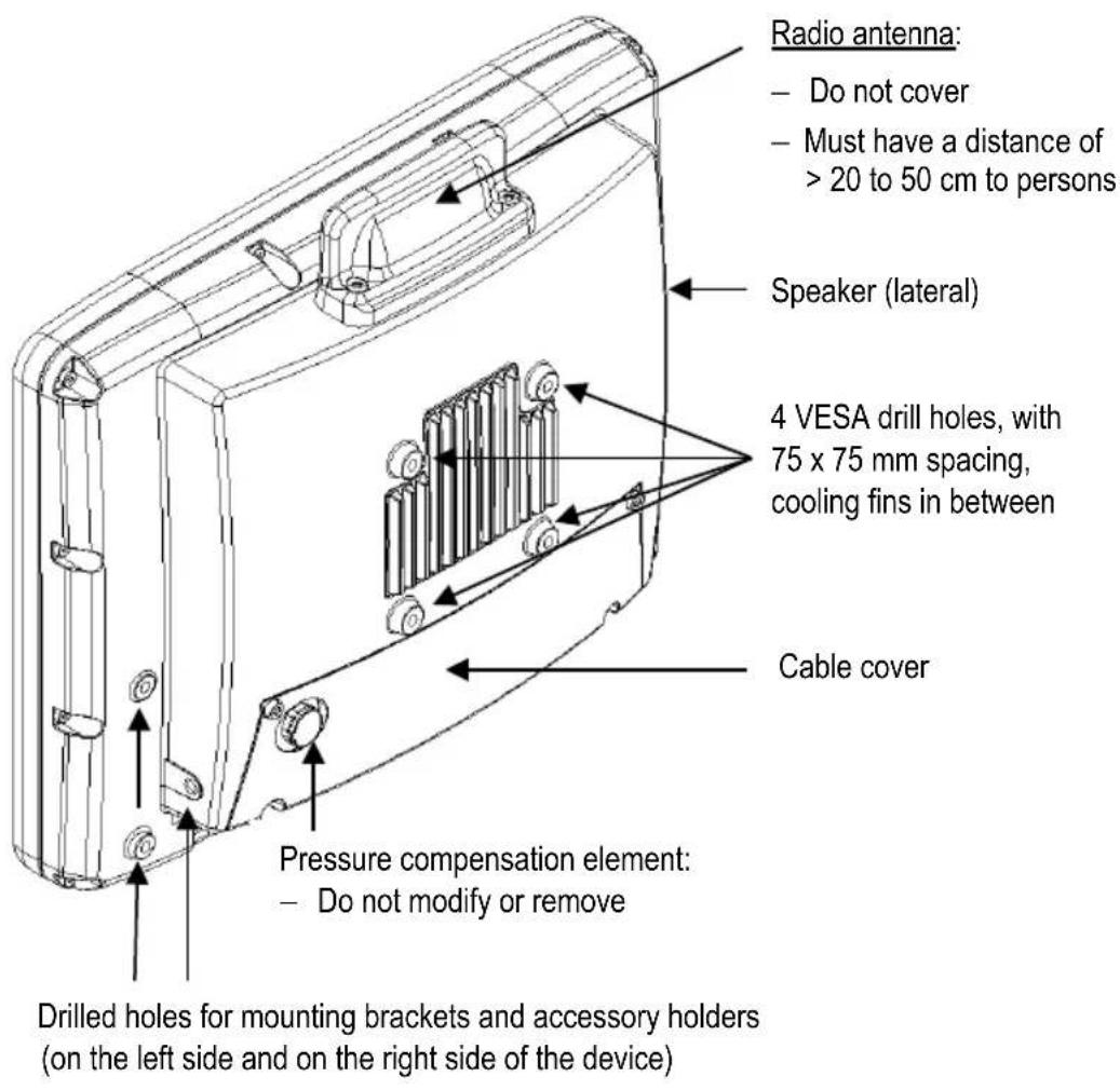
2.2 Front side (2 model variants)
A) Front with Resistive touchscreen
Available with:
- 5 front keys (as shown in the picture below)
- or 26 front keys (5 front keys as shown in the picture below plus additional numeric keys 0 to 9, arrow keys and programmable function keys)
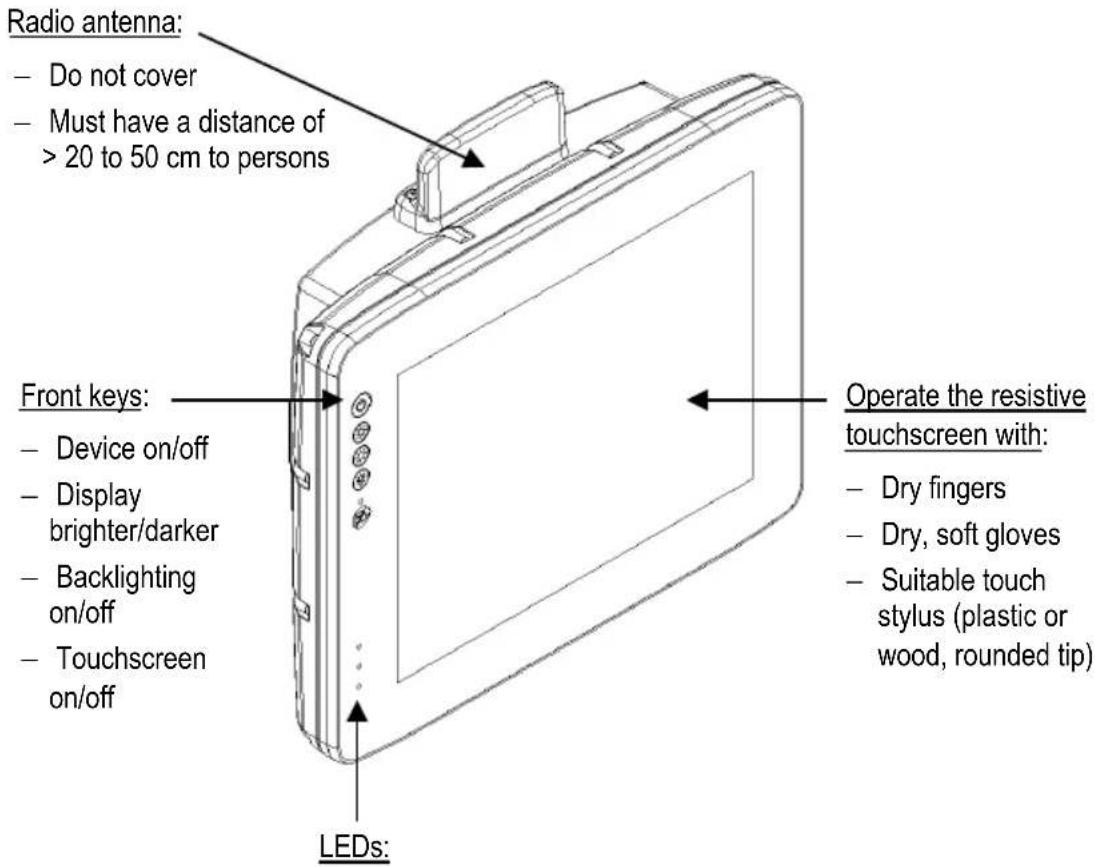
- Temperature (Red = temperature in the device is below or above the normal range)
- Access to the flash drive
- Supply voltage (Green = supply voltage available)
B) Front with PCT touchscreen
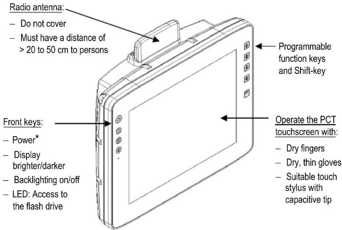
* The color of the power key indicates the following:
| white | Device is starting |
| blue | Device is on |
| red | Temperature in the device is below or above the normal range |
3 EXTERNAL CONNECTORS
3.1 In the cable compartment under the cable cover
DLT-V83 Series: DC variant, maximum equipment level (optional)
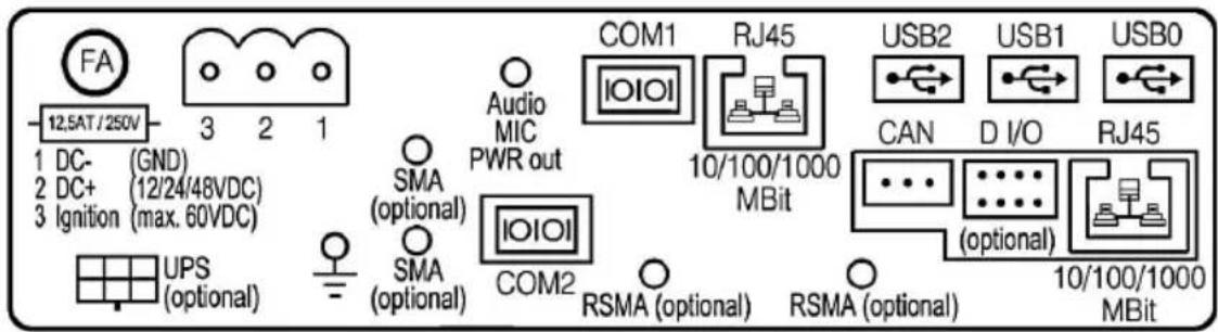
| Pin assignment (standard) | |
| Power supply | 12/24/48 VDC nominal |
| UPS (optional) | Uninterrupted power supply (UPS) |
| 2 x SMA (optional) | WWAN/GPS |
| Audio MIC PWR out | Voice kit |
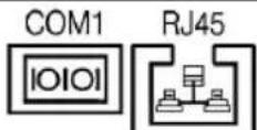
| COM1, COM2 | Serial interfaces |
| 2 x RSMA (optional) | Remote WLAN antenna |
| RJ45 | LAN Ethernet 10/100/1000 MBit/s |
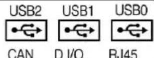
| USB2, USB1, USB0 | USB 2.0 interface (HI-SPEEDTM), bootable |
| Expansion interfaces package 1 (optional) | |
| D I/O | Digital In/Out |
| RJ45 | LAN Ethernet 10/100/1000 MBit/s |
| Expansion interfaces package 2 (optional) | |
| CAN | CAN interface |
| D I/O | Digital In/Out |
| RJ45 | LAN Ethernet 10/100/1000 MBit/s |
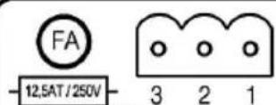
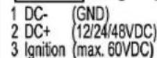
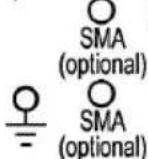
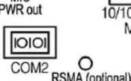
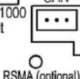
DLT-V8315: AC variant, maximum equipment level (optional)
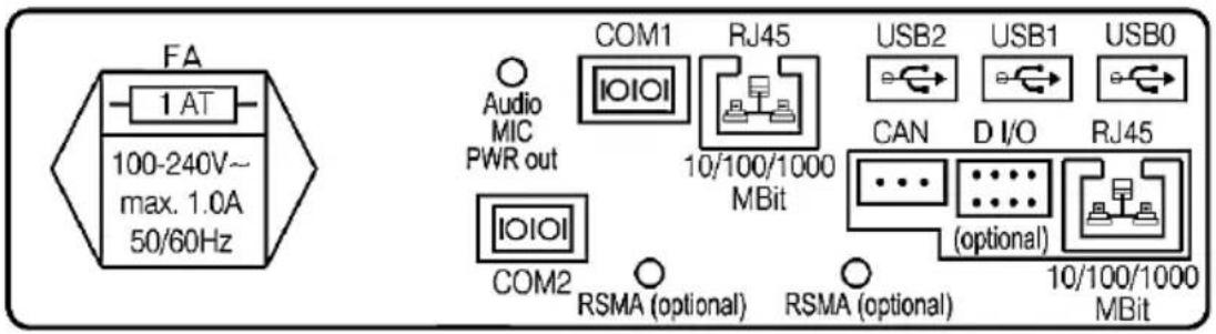
| Pin assignment (standard) | |
| Power supplyDLT-V8315 | 100 up to 240 VAC |
| Audio MIC PWR out | Voice kit |
| COM1, COM2 | Serial interfaces |
| 2 x RSMA (optional) | Remote WLAN antenna |
| RJ45 | LAN Ethernet 10/100/1000 MBit/s |
| USB2, USB1, USB0 | USB 2.0 interface (HI-SPEEDTM), bootable |
| Expansion interfaces package 1 (optional) | |
| D I/O | Digital In/Out |
| RJ45 | LAN Ethernet 10/100/1000 MBit/s |
| Expansion interfaces package 2 (optional) | |
| CAN | CAN interface |
| D I/O | Digital In/Out |
| RJ45 | LAN Ethernet 10/100/1000 MBit/s |
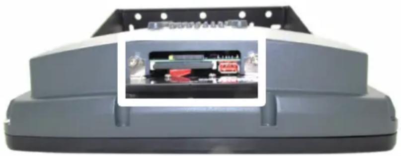
3.2 Connectors underneath the antenna
(or underneath the protective cap, for devices without radio equipment)
natural_image
Exterior view of a gray plastic enclosure with a white inset showing internal components (no visible text or symbols)Connectors:
- Service-USB (USB 2.0 Host, HI-SPEED™)
- CFast slot
- Mini-SIM card slot
NOTICE: Physical damage
- Switch off the DLT-V83 before the protective cap or antenna is removed.
- Only insert/remove the Mini-SIM card, CFast card and USB stick when the device has been completely de-energized.
Protective caps or antennas:
- Are only permitted to be removed for servicing purposes, e.g. to install software updates.
— Are only permitted to be removed by qualified expert personnel.
Several antenna types are secured to the radio card inside the device using thin antenna connection cables.
- Remove these antennas from the device with great care as the antenna connection cables can become detached from the antenna and from the radio card, meaning that radio operation is no longer possible.

Refer to the description and required tools for opening the antenna in the "DLT-V83 Operating Instructions".
4 CONFIGURATION (FRONT KEYS, RADIO)
4.1 General
Basic settings for the DLT-V83 are defined in advance at the factory, e.g.:
- Network settings
- Front-key assignment
- Functional method of the automatic shutdown function, etc.
To adapt these settings, please use the configuration tool for the corresponding operating system on your DLT-V83, e.g. the DLoG Config Tool for DLT-V83 devices with MS-Windows.
4.2 Configuring radio functionality (WLAN, WWAN)
The following preparations have already been carried out at the factory for the optional radio functionality of the DLT-V83:
- The radio card and the corresponding drivers are installed.
- A default profile with basic settings is defined.

Please find WLAN and WWAN configuration details in the "DLT-V83 Operating Instructions".

WARNING
Radiation emission
DLT-V83 devices with radio equipment emit high frequency energy (abbreviation: HF). To protect persons against HF radiation:
- Mount the DLT-V83 so that persons maintain a minimum distance of 20 to 50~cm from the radio antennas.
- Ensure that persons observe this minimum distance when operating the DLT-V83.
5 NOTES ON THE MECHANICAL MOUNTING
5.1 Overview: Recommended mounting sequence
- Find a suitable installation position for the DLT-V83.
- Secure the device mounting (RAM or mounting bracket) to the targeted subject/vehicle.
- Connect external accessories to the DLT-V83.
- Install an easily accessible disconnecting device such as a switch close to the device.
- Connect all cables (power supply, peripherals).
- Seal cable passages with cable grommets and dummy grommets.
- Close the DLT-V83 with the cable cover.
- Install the DLT-V83 on the device mounting.
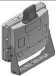
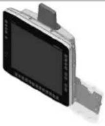
5.2 Notes about the attachment of device mounts and accessory mounts

WARNING
Risk of accident on vehicles if the mounting becomes loose
Mechanical expert knowledge is required for correct attachment of device mounts and accessory mounts on the DLT-V83.
- Use suitable mounting material.
- Observe the maximum screw-in depth of the holes of the DLT-V83:
The recommended screw-in depth of D x 1 always applies (screw diameter x 1).
ATTENTION: Screws that are too long, e.g. in the VESA mounting holes, can pierce the rear side of the DLT-V83 and cause irreparable damage to the device.
Mounting examples:
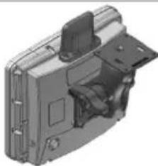
| Device mount: RAM Mount solution | Device mount: ADLoG mounting bracket | Accessory mount: 24-key keypad | |||
 |  |  | |||
6 NOTES ON THE ELECTRICAL INSTALLATION
Available power supply units
Integrated direct current (DC) power supply unit
Available for all device variants of the DLT-V83 series:
— Integrated, galvanically separated direct current power supply unit
- 12/24/48 VDC nominal (wide-range power supply unit)
- 60 W / 80 W internal, type DC-16
– Voltage range 9 to 60 VDC
NOTICE: Property damage
Fit fuses to the following supply lines:
- The DC+ connecting cable must be protected by a fuse (max. 30 AT).
- The ignition connecting cable must be protected by a fuse of the following type: 5x20 mm T 125 mA L / 250 V, for example Wickmann 195-125 mA / 250 V.
Integrated alternating current (AC power supply unit)
Only available for the DLT-V8315 device variant:
— Integrated, galvanically separated alternating current power supply unit, type AC-4
– Nominal voltage 100 to 240 VAC
– Voltage range 85 to 264 VAC
- Connection to the power supply on the underside of the device via an angled connector for non-heating apparatus

WARNING
Danger of death due to hazardous voltage, electric shock.
- Do not open DLT-V83 devices with AC power supply unit while they are connected to the power supply; doing so represents a danger to life.
- Before installing, observe the "DLT-V83 Operating Instructions", "AC devices" section.
7 CONNECT CABLES, SEAL CABLE PASSAGES
7.1 Required components
A) Cable sealing set
| Cable sealing set components | |
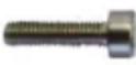 | 10 x cylinder head screws DIN 912 M3x12 for fastening the cables to the strain relief rail |
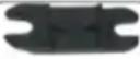 | 7 x cable clips for fastening the cables to the strain relief rail |
 | 10 x cable grommets (different size openings); must be fitted to all cables before they are inserted into the cable passages. |
 | 6 x dummy grommets to seal cable passages on the device that are not required |
Note: Some screws and grommets in the scope of delivery are replacement parts.
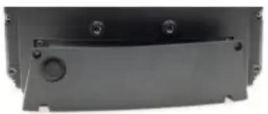
B) Cable cover
- Cable cover without integrated UPS battery pack (see below picture, left)
- Or: Cable cover with integrated UPS battery pack (see below picture, right)
- Thin shaft screws, self-retaining in the holes (4 x M4x12, thread length 4 mm)
natural_image
Close-up of a black plastic enclosure with mounting holes and a central circular feature (no text or symbols visible)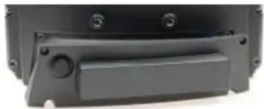
natural_image
Close-up of a black plastic electronic component with mounting holes and a rectangular slot (no visible text or symbols)C) Power supply cable
– DC power supply cable with Phoenix contact connector
- Or: AC power supply cable with angled connector for non-heating apparatus with on/off switch for the grid power
7.2 Procedure
STEP 1: Plug in the power supply cable
Plug the relevant power supply cable (AC or DC) into the corresponding slot on the DLT-V83.
For DC devices only: Secure the power supply cable, ensure a proper electrical connection
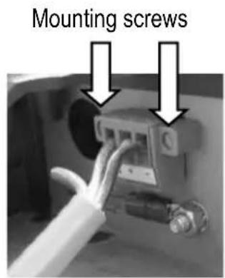
- Plug the DC power supply cable into the DC slot.
- Tighten the mounting screws hand-tight.
natural_image
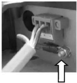
Close-up of a mechanical component with a white cable and pipe, no visible text or symbolsGround bolt, with the following components factory-fitted:
- 1 x toothed washer D=8.5 d=4.2 t=0.5 ST Ni
-
1 x nut (W) W=6 M4*0.7 H=2.5 ST Zn
-
Remove the nut from the ground bolt.
The toothed washer remains on the ground bolt. - Plug the ring tongue on the power supply cable onto the ground bolt; the flat side of the ring tongue points towards the DLT-V83 connector panel.
- Lastly, fit the nut and fasten it.
NOTICE: For a proper electrical connection, it is important to have the correct order of the components on the ground bolt (from inside to outside):
| Toothed washer (internal) |  |
| Ring tongue on the power supply cable (center) | 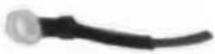 |
| Nut (external) |  |
From STEP 2 the information applies to all devices, AC and DC!
STEP 2: Fit cable grommet onto power supply cable (AC or DC variant) and secure to the strain relief

- Fit a suitable cable grommet onto the power supply cable.
NOTICE: The cable grommet must completely surround the cable.
The opening of the cable grommet must be slightly smaller than the cable diameter.
If the opening is too large or too small, the sealing of the device will not be ensured.
- Place the power supply cable, plus cable grommet, into the strain relief rail cable passage.
- Place one cable clip on the power supply cable.
- Secure the cable clip to the strain relief rail using 2 mounting screws (M3x5L).
- Tighten the mounting screw with alternating force.
NOTICE:
- Tighten the mounting screws sufficiently but make sure not to pinch the cable. Otherwise, the cables may break or the insulation may be damaged.
- Make sure that the power supply cables are run without kinks and are mechanically protected (securely protected against crushing and abrading).
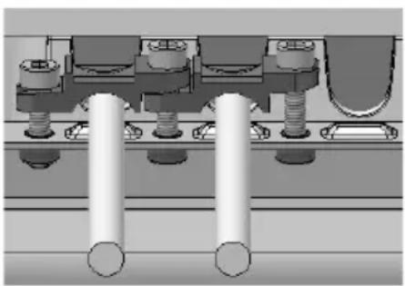
The graphic shows the mounting system for all cables to be connected:
natural_image
Mechanical assembly diagram showing two cylindrical components mounted on a base with bolts and housing (no text or symbols visible)- Appropriate cable grommet on the cable
— Insert into the cable passage - Secure using cable clip and screws to the strain relief rail
STEP 3: Connect the USB, Ethernet and COM cables
Procedure as described for the power supply cable:
- Connect the cable.
- Fit the appropriate cable grommet to the cable.
- Insert both components into the cable passage.
- Secure using cable clip and screws to the strain relief rail.
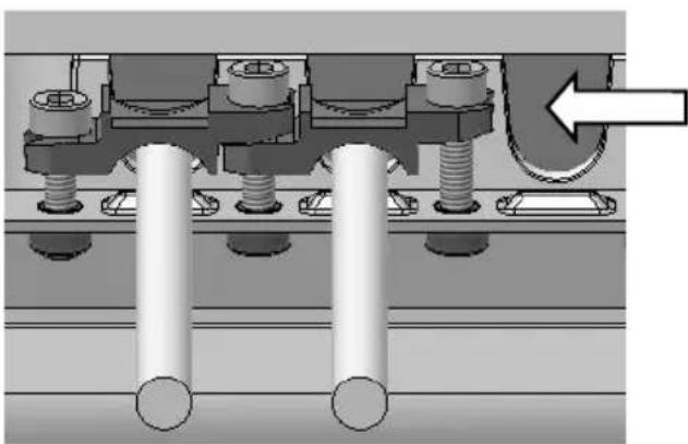
STEP 4: Close off unused cable openings
natural_image
Mechanical assembly diagram showing two parallel cylindrical components connected to a housing with a directional arrow (no text or symbols)Close off all unused cable passages with dummy grommets so that they are sealed.
8 ATTACHING THE CABLE COVER
To prevent fluids or dust penetrating the DLT-V83 during ongoing operation, the cable compartment on the device must be sealed using the corresponding cable cover. The protection class is only ensured if the cable cover is properly installed.
8.1 Attaching the cable cover without integrated UPS battery
— Place the cable cover in the DLT-V83 housing slot.
- Tighten the thin shaft screws (self-retaining) loosely.
- Then fully tighten the screws alternately (crosswise) to a torque of 3Nm .
8.2 OR: Attaching the cable cover with integrated UPS battery

WARNING
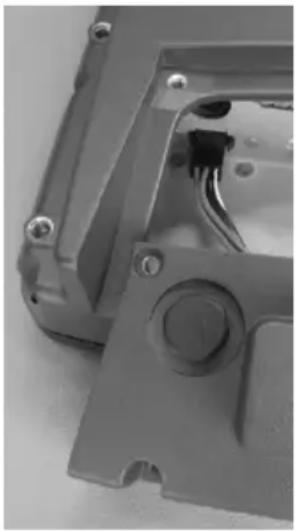
Cable cover contains battery pack. Before connecting and disconnecting the cable cover, the DLT-V83 must be de-energized.
natural_image
Close-up of a mechanical device with visible internal components and mounting holes (no text or symbols)- Hold the cable cover against the bottom edge of the DLT-V83, as shown in the picture.
The connecting cables of the UPS must point in the direction of the connector panel. - Insert the connector, with the latch aligned correctly, into the connector panel socket marked UPS optional.
- Place the cable cover into the housing groove of the DLT-V83.
— Make sure that the battery cable is not jammed. - Tighten the thin shaft screws (self-retaining) loosely in the holes of the cable cover.
- Then fully tighten the screws crosswise to a torque of 3 Nm.
FOR YOUR NOTES
No. 1, Alley 20, Lane 26, Rueiguang Road,
Neihu District, Taipei 11491, Taiwan, R.O.C.
natural_image
Close-up of a black plastic mechanical component with a blue arrow pointing to a button (no text or symbols visible)natural_image
Exterior view of a gray plastic enclosure with a small inset image showing internal components (no visible text or symbols)Anschlüsse:
— Service-USB (USB 2.0 Host, HI-SPEED™)
- CFast-Slot
- Mini-SIM-Karten-Slot
natural_image
Close-up of a black plastic enclosure with mounting holes and a circular button (no text or symbols visible)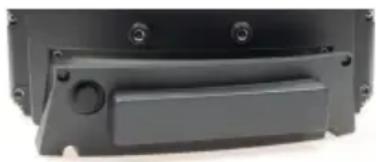
natural_image
Close-up of a black plastic electronic component with mounting holes and a handle (no visible text or symbols)natural_image
Close-up of a cable inserted into a device socket, with two white arrows pointing to the ports (no text or symbols visible)natural_image
Close-up of a white cable inserted into a mechanical component with a white arrow pointing upward (no text or symbols visible)natural_image
Mechanical assembly diagram showing two cylindrical components mounted on a base with no visible text or symbolsnatural_image
Mechanical assembly diagram showing bolted connections and a directional arrow (no text or symbols)Alle unbenutzten
natural_image
Close-up of a gray plastic mechanical component with visible pins and internal wiring (no text or symbols)natural_image
Close-up of a black plastic mechanical component with a blue arrow pointing to a button (no text or symbols visible)natural_image
Exterior view of a gray plastic enclosure with a white inset showing internal components (no visible text or symbols)连接件:
natural_image
Close-up of a black plastic enclosure with mounting holes and a circular button (no text or symbols visible)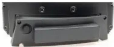
natural_image
Close-up of a black plastic electronic component with mounting holes and a rectangular slot (no visible text or symbols)C)电源线
natural_image
Mechanical assembly diagram showing two cylindrical components mounted on a base with bolts and housing (no text or symbols visible)natural_image
Mechanical assembly diagram showing two parallel cylindrical components connected to a central shaft with a directional arrow (no text or labels)natural_image
Close-up of a mechanical device with mounting holes and a central screw (no visible text or symbols)Radio Equipment Directive (RED) 2014/53/EU
RED-Doc V2.03
2019-11-06
No.1, Alley 20, Lane 26, Rueiguang Road, Neihu District, Taipei 11491, Taiwan, R.O.C.
The importer:
Advantech Service-IoT GmbH
Industriestrasse 15, 82110 Germering, Germany
Hereby declare that the following products
Product name: Industrial Computer
Model names: DLT-M8110, DLT-V6210, DLT-V4108, DLT-V72xx, DLT-V83xx
Comply with the provisions of the applicable EU directives, including their amendments applicable at the time of the declaration. For getting the detailed declarations of conformity please visit our websites and contact your regional person in charge: www.advantech.com / www.advantech.eu / www.advantech-service-iot.eu
WLAN cards: SUMMIT/LAIRD SDC-PE15N / WPEA-251N (BT) / WPEA-252NI
| Band 1: WLAN 2.4 GHz | |
| Frequency range | 2400 to 2485 MHz |
| Frequency band ETSI Europe | 2.4 GHz to 2.483 GHz |
| Channels available | 1 to 13 |
| Supported standards | WLAN IEEE 802.11 a/b/g/n |
| Maximum TX: | 100 mW / 20 dBm |
| Band 2: WLAN 5 GHz | |
| Frequency range | 5150 to 5875 MHz |
| Frequency band ETSI Europe | 5.15 GHz to 5.35 GHz5.47 GHz to 5.725 GHz |
| Channels available | 36 to 165 |
| Supported standards | WLAN IEEE 802.11 a/n |
| Maximum TX | 100 mW / 20 dBm |
WLAN card SPARKLAN WPEQ-261ACN (BT)
| Band 1: WLAN 2.4 GHz | |
| Frequency range | 2400 to 2485 MHz |
| Frequency band ETSI Europe | 2.4 GHz to 2.483 GHz |
| Channels available | 1 to 13 |
| Supported standards | WLAN IEEE802.11 a/b/g/n/ac and Bluetooth, both supported via a single antenna |
| Maximum TX | 100 mW / 20 dBm |
| Band 2: WLAN 5 GHz | |
| Frequency range | 5150 to 5875 MHz |
| Frequency band ETSI Europe | 5.15 GHz to 5.35 GHz5.47 GHz to 5.725 GHz |
| Channels available | 36 to 165 |
| Supported standards | WLAN IEEE802.11 a/b/g/n/ac |
| Maximum TX | 100 mW / 20 dBm |
WWAN card SIERRA WIRELESS MC8092 (WWAN 3G)
| Band Frequencies | Conducted Tx Power | ||
| Average | Notes | ||
| GSM Bands | |||
| GSM 850 | TX: 824 to 849 MHz | +33 ± 2 dBm | GMSK, connectorized (Class 4) |
| EGSM 900 | TX: 880 to 915 MHz | +33 ± 2 dBm | GMSK, connectorized (Class 4) |
| DCS 1800 | TX: 1710 to 1785 MHz | +30 ± 2 dBm | GMSK, connectorized (Class 1) |
| PCS 1900 | TX: 1850 to 1910 MHz | +30 ± 2 dBm | GMSK, connectorized (Class 1) |
WWAN card QUECTEL EC25E (WWAN 2G, 3G, 4G cellular bands and GNSS)
| TX | |
| Class 3 (23 dBm ± 2 dB) for LTE FDD | Class E2 (27 dBm ± 3 dB) for EDGE 850/900 MHz |
| Class 3 (23 dBm ± 2 dB) for LTE TDD | Class E2 (26 dBm + 3/-4 dB) for EDGE 1800/1900 MHz |
| Class 3 (24 dBm + 1/-3 dB) for TD-SCDMA | Class 4 (33 dBm ± 2 dB) for GSM 850/900 MHz |
| Class 3 (24 dBm + 1/-3 dB) for WCDMA | Class 1 (30 dBm ± 2 dB) for GSM 1800/1900 MHz |
To protect humans and domestic animals against RF exposure:
Ensure that antennas have a distance of 20 cm to 50 cm to humans and domestic animals.
Observe all applicable regulations for your deployment location/country with regard to frequencies and the maximum permissible TX power.
Any changes or modifications which are not expressly approved by the party responsible for the compliance can lead to the withdrawal of the operating license and guarantee for this device.
www.advantech.com
Please verify specifications before quoting. This guide is intended for reference purposes only.
All product specifications are subject to change without notice.
No part of this publication may be reproduced in any form or by any means, electronic, photocopying, recording or otherwise, without prior written permission of the publisher.
All brand and product names are trademarks or registered trademarks of their respective companies.
© Advantech Co., Ltd. 2019
Startup Manual
P/N 20080V8301
- DLT-V83 Series Industrial Computer
- DLT-V83
- EN: Startup Manual – Content Overview
- WICHTIG:
- Safety Instructions
- Quick Start and Installation
- Regional Service & Customization Centers
- Worldwide Offices
- Greater China
- China
- Taiwan
- Middle East and Africa
- Asia
- Japan
- Korea
- Singapore
- Malaysia
- Thailand
- Vietnam
- India
- Indonesia
- Australia
- Europe
- Germany
- France
- Italy
- Benelux & Nordics
- UK
- Poland
- Russia
- Czech Republic
- Ireland
- Americas
- North America
- Brazil
- Mexico
- DLT-V83 Startup Manual
- English (EN): Important information
- Copyright
- Acknowledgements
- Manufacturer address
- Technical support and assistance
- DLT-V83 Industrial Computer Safety Instructions (EN)
- IMPORTANT:
- INTRODUCTION
- WARNING
- Important for your safety.
- INTENDED USE
- REQUIREMENT FOR COMMISSIONING AND OPERATING PERSONNEL
- Commissioning and maintenance
- Examples:
- Requirements for the operating personnel
- BATTERY PACK SAFETY
- EXPLOSION HAZARD! BATTERY PACK SAFETY NOTICE.
- THERE IS A RISK OF EXPLOSION IF THE BATTERY PACK IS SWAPPED OUT AND REPLACED WITH AN INCORRECT/NON-APPROVED BATTERY PACK.
- Prevent physical damage due to deep discharge.
- RADIATION EMISSION
- INFORMATION ON SAFE MOUNTING
- During the mounting process
- Choosing the mounting position and installation environment
- Specific information on vehicle mounting (forklifts, etc.)
- INFORMATION ON SAFE ELECTRICAL INSTALLATION
- Danger of electric shock
- Installing the disconnecting device
- Power supply unit fuse blows repeatedly
- DLT-V83 with DC power supply unit
- SAFETY DURING ONGOING WORK OPERATIONS
- General
- The following applies when using the DLT-V83 on vehicles:
- REGULAR MAINTENANCE WORK
- Cleaning the device
- Devices used in vehicles
- REPAIRS AND MODIFICATIONS
- Accessories and peripherals
- RECYCLING
- REGULATORY INFORMATION
- DLT-V83 Industrial Computer Quick Start and Installation (EN)
- PACKING LIST
- OVERVIEW OF IMPORTANT OPERATING ELEMENTS
- NOTICE: Property damage
- Rear side
- Front side (2 model variants)
- A) Front with Resistive touchscreen
- Available with:
- B) Front with PCT touchscreen
- EXTERNAL CONNECTORS
- In the cable compartment under the cable cover
- Connectors underneath the antenna
- Connectors:
- NOTICE: Physical damage
- Protective caps or antennas:
- CONFIGURATION (FRONT KEYS, RADIO)
- General
- Configuring radio functionality (WLAN, WWAN)
- Radiation emission
- NOTES ON THE MECHANICAL MOUNTING
- Overview: Recommended mounting sequence
- Notes about the attachment of device mounts and accessory mounts
- Risk of accident on vehicles if the mounting becomes loose
- NOTES ON THE ELECTRICAL INSTALLATION
- Available power supply units
- Integrated direct current (DC) power supply unit
- Integrated alternating current (AC power supply unit)
- Danger of death due to hazardous voltage, electric shock.
- CONNECT CABLES, SEAL CABLE PASSAGES
- Required components
- A) Cable sealing set
- B) Cable cover
- C) Power supply cable
- Procedure
- STEP 1: Plug in the power supply cable
- For DC devices only: Secure the power supply cable, ensure a proper electrical connection
- STEP 2: Fit cable grommet onto power supply cable (AC or DC variant) and secure to the strain relief
- NOTICE:
- STEP 3: Connect the USB, Ethernet and COM cables
- STEP 4: Close off unused cable openings
- ATTACHING THE CABLE COVER
- Attaching the cable cover without integrated UPS battery
- OR: Attaching the cable cover with integrated UPS battery
- FOR YOUR NOTES
- Anschlüsse:
- C)电源线
- Radio Equipment Directive (RED) 2014/53/EU
- www.advantech.com
Brand : Advantech
Model : DLV8315-4J300F0
Category : Thin client