
Edge Gateway 3003 - Uncategorized DELL - Free user manual and instructions
Find the device manual for free Edge Gateway 3003 DELL in PDF.


| Product Type | IoT Edge Gateway |
| Brand | Dell |
| Model | Edge Gateway 3003 |
| Supported Operating Systems | Windows 10 IoT Enterprise LTSB 2016, Ubuntu Core 16, Ubuntu Server 18.04 |
| Power Input | 12–57 VDC (1.08–0.23 A) or PoE 37–57 VDC |
| Power Consumption | Maximum 13 W (PoE Class 0) |
| Ethernet Ports | 2 x RJ45 (Port 1: PoE, Port 2: Non-PoE), 10/100 Mbps |
| USB Ports | 1 x USB 3.0 (5 Gbps, 0.6 A), 1 x USB 2.0 (480 Mbps, 0.4 A) |
| Display Output | 1 x DisplayPort |
| Audio | Line-out (green), Line-in (blue) – 3.5 mm jacks |
| Wireless Connectivity | WLAN (2.4/5 GHz), Bluetooth (classic and BLE), GPS, ZigBee, Mobile broadband (3G/LTE) |
| Antenna Connectors | WLAN/BT/GPS, Mobile broadband main, Mobile broadband aux (LTE only), ZigBee |
| SIM Card Slot | 1 x micro-SIM (optional) |
| SD Card Slot | 1 x micro-SD (optional) |
| Sensors | Temperature, humidity, pressure, accelerometer (MEMs) |
| Security | TPM 2.0, chassis intrusion switch, BIOS password, secure boot |
| Mounting Options | Standard, quick-mount, DIN rail, perpendicular, VESA (75 x 75 mm) |
| Operating Temperature | 0°C to 60°C (32°F to 140°F) |
| Regulatory Compliance | FCC Part 15 Class A, IC, CE |
| Watchdog Timer | Configurable in BIOS (default disabled) |
Frequently Asked Questions - Edge Gateway 3003 DELL
User questions about Edge Gateway 3003 DELL
0 question about this device. Answer the ones you know or ask your own.
Ask a new question about this device
Download the instructions for your Uncategorized in PDF format for free! Find your manual Edge Gateway 3003 - DELL and take your electronic device back in hand. On this page are published all the documents necessary for the use of your device. Edge Gateway 3003 by DELL.
USER MANUAL Edge Gateway 3003 DELL
Installation and Operation Manual
Notes, cautions, and warnings
NOTE: A NOTE indicates important information that helps you make better use of your product.
CAUTION: A CAUTION indicates either potential damage to hardware or loss of data and tells you how to avoid the problem.
WARNING: A WARNING indicates a potential for property damage, personal injury, or death.
© 2017-2018 Dell Inc. or its subsidiaries. All rights reserved. Dell, EMC, and other trademarks are trademarks of Dell Inc. or its subsidiaries. Other trademarks may be trademarks of their respective owners.
Contents
1 Overview....6
2 System views....7
Top view....7
Bottom view....8
Left view....8
Right view....11
3 Installing your Edge Gateway....12
Safety and regulatory information....12
Professional installation instructions....13
Federal Communication Commission interference statement....13
Industry Canada statement....14
Setting up your Edge Gateway....15
Activating your mobile broadband service....21
Mounting your Edge Gateway....22
Mounting the Edge Gateway using the standard-mount bracket.... 22
Mounting the Edge Gateway using quick-mount bracket....29
Attaching the cable control bars to the standard-mount bracket....37
Mounting the Edge Gateway on a DIN rail using the DIN-rail bracket....39
Mounting the Edge Gateway using the perpendicular mount....42
Mounting the Edge Gateway using a VESA mount....45
4 Setting up the ZigBee dongle....47
5 Setting up the operating system....48
Windows 10 IoT Enterprise LTSB 2016....48
Boot up and login – Direct system configuration....48
Boot up and login—Static IP system configuration....48
Restoring Windows 10 IoT Enterprise LTSB 2016....49
Windows 10 IOT Enterprise LTSB 2016 basic functions....49
Ubuntu Core 16....51
Overview....51
Boot up and log in – Direct system configuration 51
Boot up and log in – Static IP system configuration....51
Updating operating system and applications....52
Additional Ubuntu commands....52
Ubuntu Network Manager....53
Security....57
Watchdog Timer (WDT)....57
Cloud LED On/Off 58
Global Positioning Systems (GPS)....58
Snappy auto update/Autopilot....58
Accessing Snappy Store/Snapweb....58
Sensors....60
Ignition Pin....61
System Power Management....62
Restoring Ubuntu Core 16....62
Flashing a new OS image....64
Ubuntu Server....65
Overview....65
Login to the Edge Gateway using Ethernet Port 1....65
Installing or configuring Dynamic Host Configuration Protocol (DHCP) daemon....65
Login to the Edge Gateway using Ethernet Port 2....66
Ubuntu Server driver information....67
Firmware management on Ubuntu Server....67
Configure Watchdog Timer (WDT)....68
Trusted Platform Module (TPM)....69
Cloud LED On/Off....70
Advanced Linux Sound Architecture (ALSA)....70
Global Positioning Systems (GPS)....71
Sensors....71
Ignition Pin....72
System Power Management....73
Ubuntu Network Manager....75
Restoring Ubuntu Server....79
Creating the recovery USB flash drive....79
6 Accessing and updating BIOS....80
Accessing BIOS settings....80
Entering BIOS setup during POST....80
Updating BIOS....80
Using the USB invocation script....81
Flashing the BIOS from a USB flash drive....81
Updating the BIOS on a Windows system....81
Using UEFI capsule update on an Ubuntu system....82
Dell Command | Configure (DCC)....82
Edge Device Manager (EDM) 83
Default BIOS settings....83
General (BIOS level 1)....83
System configuration (BIOS level 1)....84
Security (BIOS level 1)......85
Secure boot (BIOS level 1)....86
Performance (BIOS level 1)....87
Power management (BIOS level 1)....87
POST behavior (BIOS level 1)....87
Virtualization support (BIOS level 1)....88
Maintenance (BIOS level 1)......88
System logs (BIOS level 1)....89
7 References....90
8 Appendix....91
Antenna specifications....91
De-mounting from DIN-rail bracket....92
Connecting to the Edge Gateway....93
Windows 10 IoT Enterprise LTSB 2016....93
Ubuntu Core 16....93
9 Contacting Dell....95
Overview
The Edge Gateway 3000 Series is an Internet-of-Things (IoT) device. It is mounted at the edge of a network, enabling you to collect, secure, analyze, and act on data from multiple devices and sensors. It enables you to connect with devices used in transportation, building automation, manufacturing, and other applications. The Edge Gateway has a low-power architecture, which is capable of supporting industrial automation workloads while remaining fanless to satisfy environmental and reliability requirements. It supports Windows 10 IoT Enterprise LTSB 2016 and Ubuntu Core 16 operating systems.
System views
Topics:
- Top view
- Bottom view
- Left view
- Right view
Top view
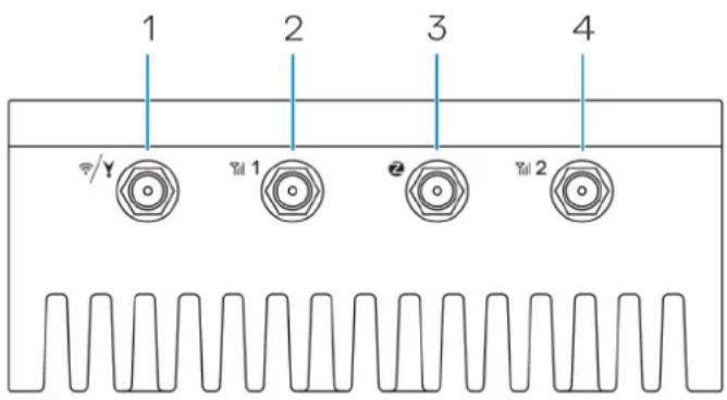
Table 1. Top view
Features
| 1 WLAN, Bluetooth, or GPS connector Connect the antenna to increase the range and strength of wireless,Bluetooth, or satellite signals. | |
| 2 Mobile broadband antenna-connector one (3G/LTE) Connect the mobile broadband antenna to increase the range andstrength of mobile broadband signals. | |
| 3 ZigBee antenna connector Connect the ZigBee antenna for intermittent data transmissions froma ZigBee-compliant sensor or input device. | |
| 4 Mobile broadband antenna-connector two (LTEAuxiliary only) | Connect the mobile broadband antenna to increase the range andstrength of mobile broadband signals. |

NOTE: Depending on the configuration ordered, some of the antenna connectors may not be present or may be capped. For more information about connecting antennas to the Edge Gateway, see the documentation that is shipped with the antenna. Antennas are available in the accessory box shipped with the Edge Gateway.
Bottom view
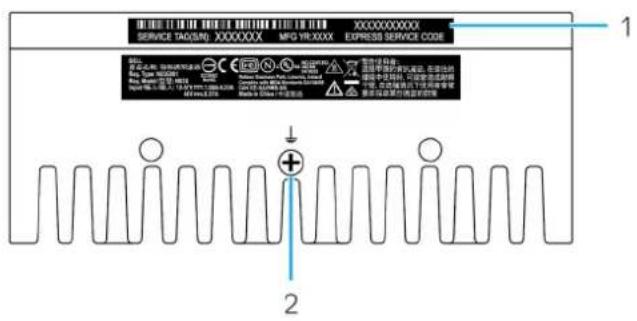
Table 2. Bottom view
Features
1 Service Tag label The Service Tag is a unique alphanumeric identifier that enables the
Dell service technicians to identify the hardware components in your Edge Gateway and access warranty information.
2 Earth ground A large conductor attached to one side of the power supply, which
serves as the common return path for current from many different components in the circuit.
Left view

Table 3. Left view
Features
1 Intrusion switch An intrusion event is triggered when the enclosure (in which the Edge Gateway is installed) is opened.
NOTE: External enclosure is sold separately.
NOTE: An intrusion event is triggered by a third-party enclosure to the Edge Gateway through a sensor. The sensor should have a cable that is compatible with the intrusion switch connector on the Edge Gateway.
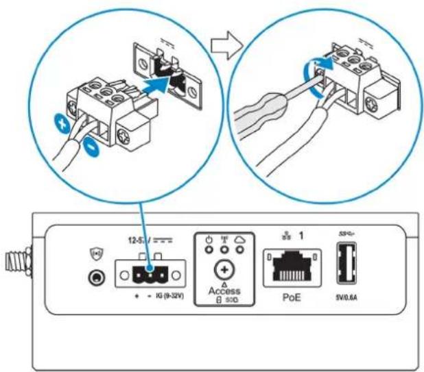
2 Power or ignition port Connect a 12-57 VDC (1.08-0.23 A) power cable to supply power to the Edge Gateway.
NOTE: Power cable is sold separately.
NOTE: For marine applications, limit input voltage to 12-48 VDC. The cable length for rail applications must not exceed 30 meters.
3 Power and System status light Indicates the power status and system status.
4 WLAN or Bluetooth status light Indicates if WLAN or Bluetooth is ON or OFF.
5 Cloud-connection status light Indicates the cloud connection status.
6 Ethernet port one (with Power over Ethernet support) Connect an Ethernet (RJ45) cable to gain network access. Provides data transfer speeds up to 10/100 Mbps and supports Alternative A of the IEEE 802.3af standard.
NOTE: The Edge Gateway is an IEEE 802.3af Alternative A compliant Powered Device (PD).
NOTE: To comply with EU Declaration of Conformity (DoC), ensure cable length from the system to the device does not exceed 30 meters.
NOTE: To comply with regulatory requirements in Brazil, ensure cable length from the system to the device does not exceed 10 meters.
For information on how to configure Ethernet settings, such as duplex configuration, see:
• Windows 10 IoT Enterprise LTSB 2016: Ethernet configuration
7 USB 3.0 port ^1 Connect a USB enabled device. Provides data transfer speeds up to 5 Gbps.
8 SIM card slot (optional) Insert a micro-SIM card into the slot.
9 SD card slot (optional) Insert a micro-SD card into the slot.
NOTE: Remove the SD card slot filler before inserting a micro-SD card.
10 Quick Resource Locator label Scan with a QR reader to access documentation and other system information.
11 micro-SIM or micro-SD card Open the access door to access the micro-SIM or micro-SD card. access door
^1 USB power is limited to 0.6 A/3 W.
Table 4. Status-light indicators
| Function | Indicator | Color | Control | Status |
| System | Power status and System status | Green or Amber | BIOS | Off: System offOn (Solid Green): System on or Boot successfulOn (Solid Amber): Power up or boot failBlinking Amber: Fault or error |
Function Indicator Color Control Status
| WLAN or Bluetooth Green Hardware Off: WLAN or Bluetooth | module is off |
| On: WLAN or Bluetooth module is on | |
| Cloud Green Software Off: No connection to the | cloud device or service |
| On: Edge Gateway connected to a cloud device or service | |
| Blinking Green: Activity to a cloud device or service | |
| LAN (RJ-45) Link Green/Amber Driver (LAN) Off: No network link or | cable is not connected |
| On (Green): High-speed connection (100 Mbps) | |
| On (Amber): Low-speed connection (10 Mbps) | |
| Activity Green Driver (LAN) Off: No activity on link | Blinking Green: LAN activity. The blink rate is related to packet density. |
NOTE: The power and system status light may operate differently during different boot-up scenarios, for example, when a USB script file is run during boot-up.
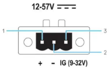
Table 5. Power connector pin definition details
| Pin | Signal | Function |
| 1 | DC+ | 12–57 VDC power |
| 2 | DC- | Ground |
| 3 | IG | 9–32 VDC ignition |
NOTE: Pin 3 (IG) is connected to the vehicle's ignition status indicator (optional) or a wake pin. A voltage of more than 9 V on the signal indicates that the vehicle's engine is running. The Ignition or Wake pin is used to prevent the draining of the vehicle battery when the vehicle is turned off for an extended amount of time.
NOTE: The IG signal can be used to gracefully shutdown or enter low-power state when the vehicle is turned off (battery powered). It can also be used for powering on the Edge Gateway when the vehicle starts.
Right view
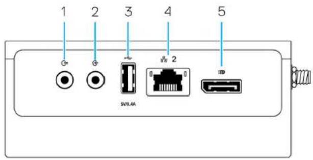
Table 6. Right view—3003
Features
1 Audio line-out (GREEN) Connect audio-output devices such as speakers and amplifiers.
2 Audio line-in (BLUE) Connect recording or playback devices.
3 USB 2.0 port 1
Connect a USB enabled device. Provides data transfer speeds up to 480 Mbps.
4 Ethernet port two (Non-PoE) Connect an Ethernet (RJ45) cable for network access. Provides data
transfer speeds up to 10/100 Mbps.
For information on how to configure Ethernet settings, such as duplex configuration, see:
• Windows 10 IoT Enterprise LTSB 2016: Ethernet configuration
5 DisplayPort connector Connect a monitor or another DisplayPort-enabled device. Provides video and audio output.
^1 USB power is limited to 0.4 A/2 W.
Installing your Edge Gateway
WARNING: Before you begin any of the procedures in this section, read the safety and regulatory information that is shipped with your system. For additional best practices information, go to www.dell.com/regulatory_compliance.
Topics:
• Safety and regulatory information
- Setting up your Edge Gateway
- Activating your mobile broadband service
- Mounting your Edge Gateway
Safety and regulatory information
WARNING: The Edge Gateway must be installed by knowledgeable, skilled persons familiar with local and/or international electrical codes and regulations.
WARNING: The Edge Gateway is not designed for use in wet environments. If the Edge Gateway is to be installed in a wet environment, depending on the location and environment, it must be installed in a panel box or enclosure with an Ingress Protection (IP) rating of IP54, IP65, or higher.
WARNING: To reduce the risk of electric shock, power to the DC+ and DC- terminals must be provided by a power supply or transformer/rectifier circuit that is designed with double-insulation. The power supply or power circuit source must comply with local codes and regulations; for example, in the USA, NEC Class 2 (SELV/limited energy circuit, or LPS circuitry). If powered by a battery, double-insulation is not required.
WARNING: When installing the Edge Gateway, the responsible party or integrator shall use the 12-57 VDC or Power over Ethernet (PoE) power source 37-57 VDC, with a minimum of 13 W power already present as part of the client's installation.
WARNING: Ensure that the power source providing power to the Edge Gateway is reliably grounded and filtered such that the peak-to-peak ripple component is less than 10 percent of the input DC voltage.
WARNING: When installing the Edge Gateway 3003, use a cable appropriate for the load currents: 3-core cable rated 5 A at 90°C (194°F) minimum, which conform to either IEC 60227 or IEC 60245. The system accepts cables from 0.8 mm to 2 mm. The maximum operating temperature of the Edge Gateway is 60°C (140°F). Do not exceed this maximum temperature while operating the Edge Gateway inside an enclosure. Internal heating of the Edge Gateway electronics, other electronics, and the lack of ventilation inside an enclosure can cause the operating temperature of the Edge Gateway to be greater than the outside ambient temperature. Continuous operation of the Edge Gateway at temperatures greater than 60°C (140°F) may result in an increased failure rate and a reduction of the product life. Ensure that the maximum operating temperature of the Edge Gateway when placed inside an enclosure is 60°C (140°F) or less.
WARNING: Always ensure that the available power source matches the required input power of the Edge Gateway. Check the input power markings next to power connector(s) before making connections. The 12-57 VDC (1.08-0.23 A) or the PoE power source must be compliant with local Electrical Codes and Regulations.
WARNING: To ensure the protection provided by the Edge Gateway is not impaired, do not use or install the system in any manner other than what is specified in this manual.
WARNING: If a battery is included as part of the system or network, the battery must be installed within an appropriate enclosure in accordance with local fire and electrical codes and laws.
WARNING: The system is for installation in a suitable industrial enclosure (provides electrical, mechanical, and fire hazard protection).
WARNING: The core module only can be wall-mounted (without the need for an additional enclosure).
Professional installation instructions
Installation personnel
This product is designed for specific applications and needs to be installed by qualified personnel with RF and regulatory-related knowledge. The general user shall not attempt to install or change the setting.
Installation location
The product shall be installed at a location where the radiating antenna is kept 20 cm from nearby persons in its normal operation condition in order to meet regulatory RF exposure requirements.
External antenna
Use only approved antenna(s). Non-approved antenna(s) may produce spurious or excessive RF transmitting power which may lead to a violation of FCC/IC limits.
Installation procedure
Refer to user's manual for installation instructions.

WARNING: Carefully select the installation position and make sure that the final output power does not exceed the limits described in the product's documentation. The violation of these rules could lead to serious federal penalties.
Federal Communication Commission interference statement
This device complies with Part 15 of the FCC Rules. Operation is subject to the following two conditions: (1) This device may not cause harmful interference, and (2) this device must accept any interference received, including interference that may cause undesired operation.
This equipment has been tested and found to comply with the limits for a Class A digital device, pursuant to Part 15 of the FCC Rules. These limits are designed to provide reasonable protection against harmful interference in a residential installation. This equipment
generates, uses, and can radiate radio frequency energy and, if not installed and used in accordance with the instructions, may cause harmful interference to radio communications. However, there is no guarantee that interference will not occur in a particular installation. If this equipment does cause harmful interference to radio or television reception, which can be determined by turning the equipment off and on, the user is encouraged to try to correct the interference by one of the following measures:
- Reorient or relocate the receiving antenna.
- Increase the separation between the equipment and receiver.
- Connect the equipment into an outlet on a circuit different from that to which the receiver is connected.
- Consult the dealer or an experienced radio/TV technician for help.
FCC caution:
- Any changes or modifications not expressly approved by the party responsible for compliance could void the user's authority to operate this equipment.
- This transmitter must not be co-located or operating in conjunction with any other antenna or transmitter.
Radiation exposure statement:
This equipment complies with FCC radiation exposure limits for an uncontrolled environment. This equipment should be installed and operated with a minimum distance of 20 cm between the active transceiver and your body.

NOTE: The country code selection is for a non-US model only and is not available to all US model. Per FCC regulation, all WiFi products marketed in the US must be fixed to US operation channels only.
Industry Canada statement
This device complies with Industry Canada license-exempt RSS standard(s). Operation is subject to the following two conditions:
1 this device may not cause interference, and
2 this device must accept any interference, including interference that may cause undesired operation of the device.
Under Industry Canada regulations, the radio transmitter(s) may only operate using an antenna(s) of a type and maximum (or lesser) gain approved for the transmitter(s). To reduce potential radio interference to other users, the antenna type(s) and gain(s) should be chosen so that the Equivalent Isotropic Radiated Power (E.I.R.P.) is not more than what was approved for the transmitter(s).
This Class A digital apparatus complies with Canadian ICES-003.
This device complies with RSS-210 of Industry Canada. Operation is subject to the condition that this device does not cause harmful interference.
This device and its antenna(s) must not be co-located or operating in conjunction with any other antenna or transmitter, except tested built-in radios.
The County Code Selection feature is disabled for products marketed in the US/Canada.
Radiation Exposure Statement: This equipment complies with IC radiation exposure limits set forth for an uncontrolled environment. This equipment should be installed and operated with minimum distance of 20 cm between the active transceiver and your body.
NOTE: Edge Gateway mounting options are sold separately.
NOTE: Mounting can be done before or after configuring your Edge Gateway. For more information about mounting your Edge Gateway, see Mounting your Edge Gateway.
NOTE: In some environments where the Edge Gateway may be installed, a more robust mounting method is required. For example, for mounting in marine applications, it is recommended to use only the standard—mount bracket. The recommendation is due to the presence of vibrations unique to the marine environment.
1 Use USB cables to connect a display, keyboard, and mouse.
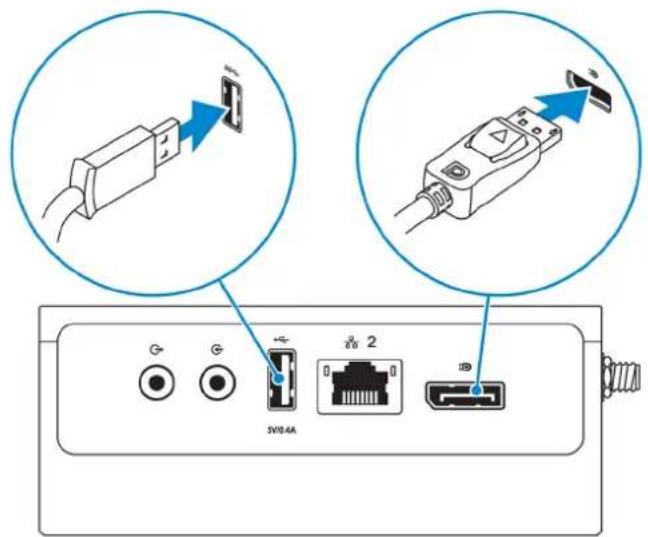
NOTE: USB power is limited to 0.6 A/3 W for USB 3.0 port and 0.4 A/2 W for USB 2.0 port to ensure that the Edge Gateway is within the allowed 13 W PoE Class 0 range.
2 Connect an Ethernet cable to Ethernet port one.
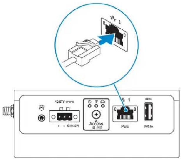
3 Connect the antennas depending on the configuration ordered (optional).
NOTE: The antennas supported in the Edge Gateway vary depending on the configuration ordered. Antennas are available in the accessory box shipped with the Edge Gateway.
Table 7. Antennas supported in Edge Gateway 3003

3003 Yes Yes Yes Not applicable Yes
NOTE: Use only the supplied antennas or third-party antennas that meet the minimum specifications.
NOTE: Depending on the configuration ordered, some of the antenna connectors may not be present or may be capped.
NOTE: Mobile broadband antenna connector two is for LTE Auxiliary only; it does not support 3G.
4 Insert the antenna into the connector.
NOTE: If you are installing multiple antennas, follow the sequence indicated in the following image.
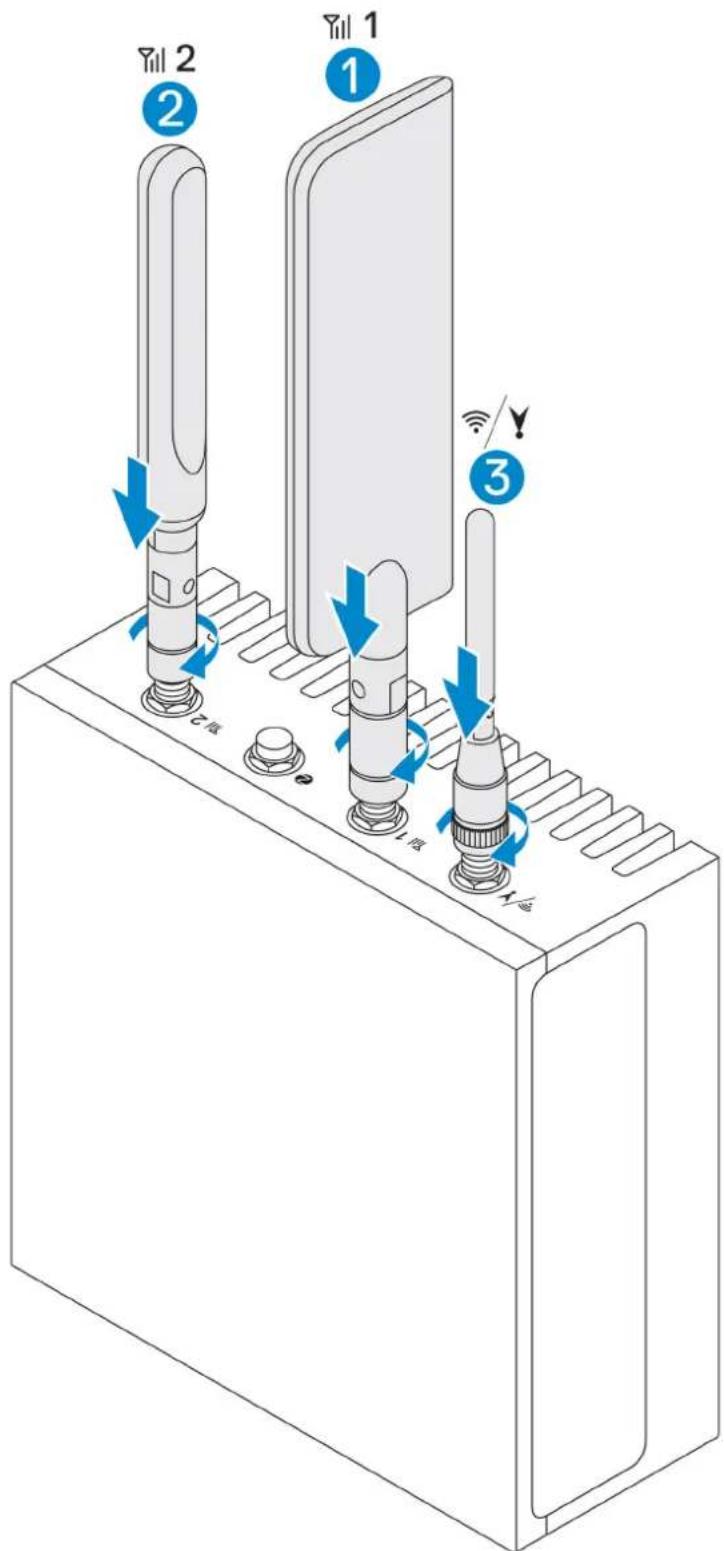
5 Secure the antenna by tightening the rotating head of the connector until it firmly holds the antenna in the preferred position (upright or straight).
NOTE: Antenna images are for illustrative purposes only. Actual appearance may differ from the images provided.
6 Connect all desired cables to the appropriate I/O ports on the Edge Gateway.
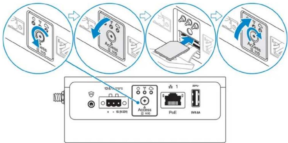
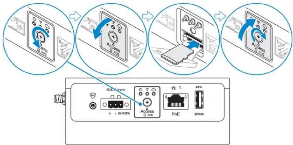
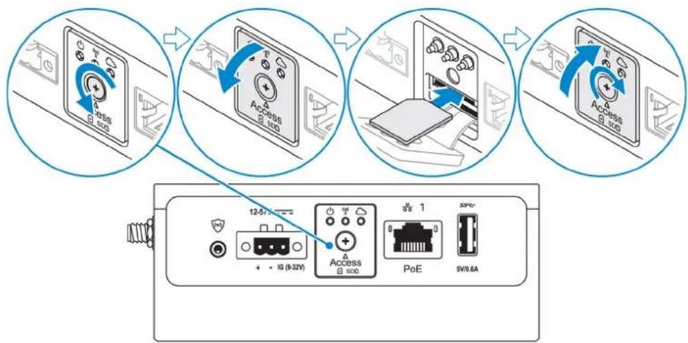
7 Open the micro-SIM or micro-SD card access door.
8 Insert a micro-SIM card into the top micro-SIM card slot and activate your mobile broadband service.
CAUTION: Dell recommends that you insert the micro-SIM card before turning on the Edge Gateway.
NOTE: Ensure that you firmly screw back the access door after closing.
NOTE: Contact your service provider to activate your micro-SIM card.
flowchart
graph TD
    A["Network Switch"] --> B["Access 100"]
    B --> C["Network Switch"]
    C --> D["Network Switch"]
    D --> E["Network Switch"]
    E --> F["Network Switch"]
    F --> G["Network Switch"]
    G --> H["Network Switch"]
    H --> I["Network Switch"]
    I --> J["Network Switch"]
    J --> K["Network Switch"]
    K --> L["Network Switch"]
    L --> M["Network Switch"]
    M --> N["Network Switch"]
    N --> O["Network Switch"]
    O --> P["Network Switch"]
    P --> Q["Network Switch"]
    Q --> R["Network Switch"]
    R --> S["Network Switch"]
    S --> T["Network Switch"]
    T --> U["Network Switch"]
    U --> V["Network Switch"]
    V --> W["Network Switch"]
    W --> X["Network Switch"]
    X --> Y["Network Switch"]
9 Insert a micro-SD card into the bottom micro-SD card slot.
flowchart
graph TD
    A["12.5V"] --> B["USB"]
    B --> C["10 (9.32V)"]
    C --> D["Access 8.600"]
    D --> E["PoE"]
    E --> F["5V/0.6A"]
    style A fill:#f9f,stroke:#333
    style B fill:#ccf,stroke:#333
    style C fill:#cfc,stroke:#333
    style D fill:#fcc,stroke:#333
    style E fill:#cff,stroke:#333
    style F fill:#ffc,stroke:#333
NOTE: Remove the SD card slot filler before inserting a micro-SD card.
NOTE: Ensure that you firmly screw back the access door after closing.
10 Connect a grounding cable between the Edge Gateway and the secondary enclosure.
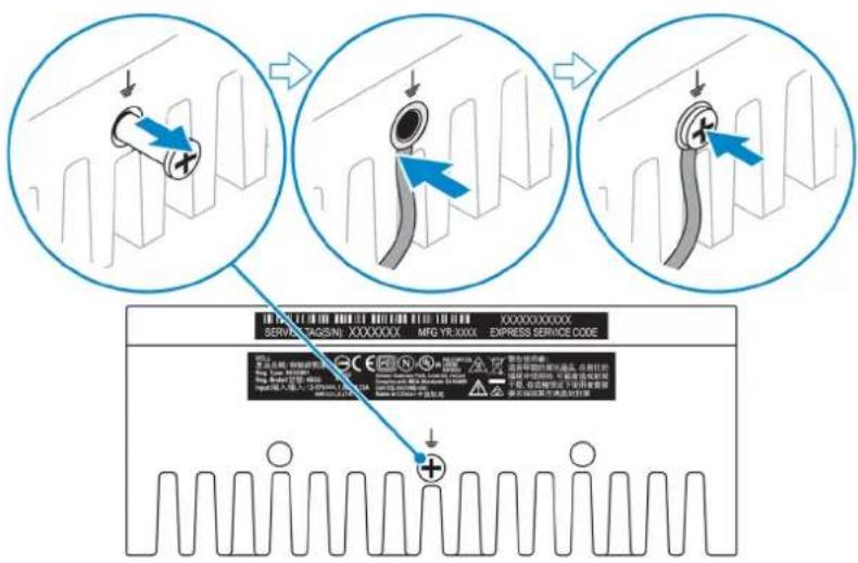
NOTE: Secondary enclosures are sold separately.
11 Connect the Edge Gateway to one of the following power sources:
· DC-IN
· PoE
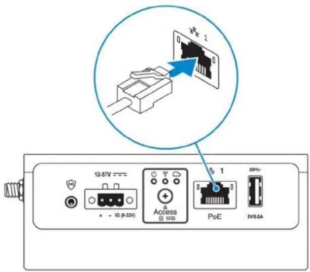
NOTE: Shut down your system before you change the power sources.
12 Replace the dust caps on any unused ports.
13 When setting up the Edge Gateway for the first time, complete the operating system setup.
For more information, see Setting up your operating system.
NOTE: MAC addresses and the IMEI number are available on the label at the front of the Edge Gateway. Remove the label at install.
NOTE: The Edge Gateway is shipped with either Windows 10 IoT Enterprise LTSB 2016 or Ubuntu Core 16 operating system.
NOTE: The default user name and password for Windows 10 IoT Enterprise LTSB 2016 isadmin.
NOTE: The default user name and password for Ubuntu Core 16 is admin.
14 Access the BIOS by pressing F2 to enter the BIOS setup or F12 to enter the BIOS boot menu.
Windows 10 IOT Enterprise LTSB 2016
Click Start > All Programs > Dell > Command Configure > Dell Command | Configure Wizard.
Ubuntu Core 16
Use the dcc.cctk command to access the Dell Command | Configure application.
NOTE: For more information about BIOS settings on the Edge Gateway, see Default BIOS settings.
15 Install the Edge Gateway using one of the following mounting options:
NOTE: An open space of 63.50 mm (2.50 in) is recommended around the Edge Gateway for optimal air circulation.
- Standard mount
• DIN rail mount - Quick mount
- Perpendicular mount
- Cable control bar
• VESA mount
Activating your mobile broadband service

CAUTION: Before you power on the Edge Gateway, insert a micro-SIM card.

NOTE: Ensure that the service provider has already activated the micro-SIM card before you use it in the Edge Gateway.
1 Remove the screw to open the micro-SIM card access door.
2 Insert a micro-SIM card into the top micro-SIM card slot.
flowchart
graph TD
    A["Network Switch"] --> B["Access 10G"]
    B --> C["Network Switch"]
    C --> D["Network Switch"]
    D --> E["Network Switch"]
    E --> F["Network Switch"]
    F --> G["Network Switch"]
    G --> H["Network Switch"]
    H --> I["Network Switch"]
    I --> J["Network Switch"]
    J --> K["Network Switch"]
    K --> L["Network Switch"]
    L --> M["Network Switch"]
    M --> N["Network Switch"]
    N --> O["Network Switch"]
    O --> P["Network Switch"]
    P --> Q["Network Switch"]
    Q --> R["Network Switch"]
    R --> S["Network Switch"]
    S --> T["Network Switch"]
    T --> U["Network Switch"]
    U --> V["Network Switch"]
    V --> W["Network Switch"]
    W --> X["Network Switch"]
    X --> Y["Network Switch"]
3 Replace the screw, and close the micro-SIM card access door.
4 Power on the Edge Gateway.
5 Connect to a mobile network.
Windows operating system
a Click the network icon from the taskbar, and then click Cellular.
b Select Mobile Broadband Carrier > Advanced Options.
c Make a note of the International Mobile Equipment Identity (IMEI) and Integrated Circuit Card Identifier (ICCID).
d Enter your APN number and any other credentials that your service provider requires.
Ubuntu operating system
a Open the Terminal window.
b Enter \$ sudo su - to access super user mode.
c Configure the Mobile Broadband connection profile:
Command line:
network-manager.nmcli con add type <type> ifname <ifname> con-name <connection-name> apn <apn>
Example (Verizon):
network-manager.nmcli con add type gsm ifname cdc-wdm0 con-name VZ_GSMDEMO apn vzwinternet
Example (AT&T):
network-manager.nmcli con add type gsm ifname cdc-wdm0 con-name ATT_GSMDEMO apn broadband
Example (3G):
network-manager.nmcli con add type gsm ifname cdc-wdm0 con-name 3G_GSMDEMO apn internet
d Connect to the mobile network:
Command line:
network-manager.nmcli con up <connection-name>
Example (Verizon):
network-manager.nmcli con up VZ_GSMDEMO
Example (AT&T):
network-manager.nmcli con up ATT_GSMDEMO
Example (3G):
network-manager.nmcli con up 3G_GSMDEMO
To disconnect from the mobile network:
Command line: network-manager.nmcli con down
Example (Verizon):
network-manager.nmcli con down VZ_GSMDEMO
Example (AT&T):
network-manager.nmcli con down ATT_GSMDEMO
Example (3G):
network-manager.nmcli con down 3G_GSMDEMO
Mounting your Edge Gateway
NOTE: Mounting can be completed before or after configuring your Edge Gateway.
NOTE: Mounting options are sold separately. Mounting instructions are available in the documentation shipped with the mounting device.
NOTE: In some environments where the Edge Gateway is installed, a more robust mounting method is required. For example, in marine applications, due to vibrations unique to that environment, only standard-mount bracket should be used.
Mounting the Edge Gateway using the standard-mount bracket
Mounting dimensions
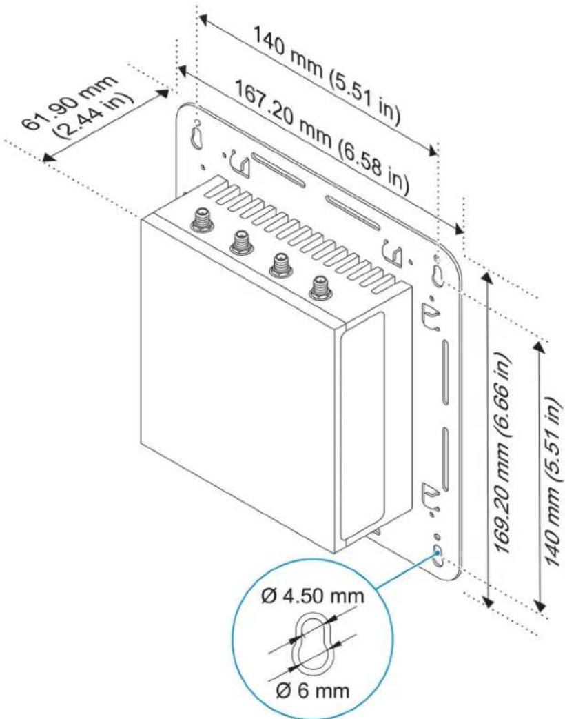
NOTE: The mounting brackets are shipped with only those screws that are required for securing the mounting brackets to the Edge Gateway.
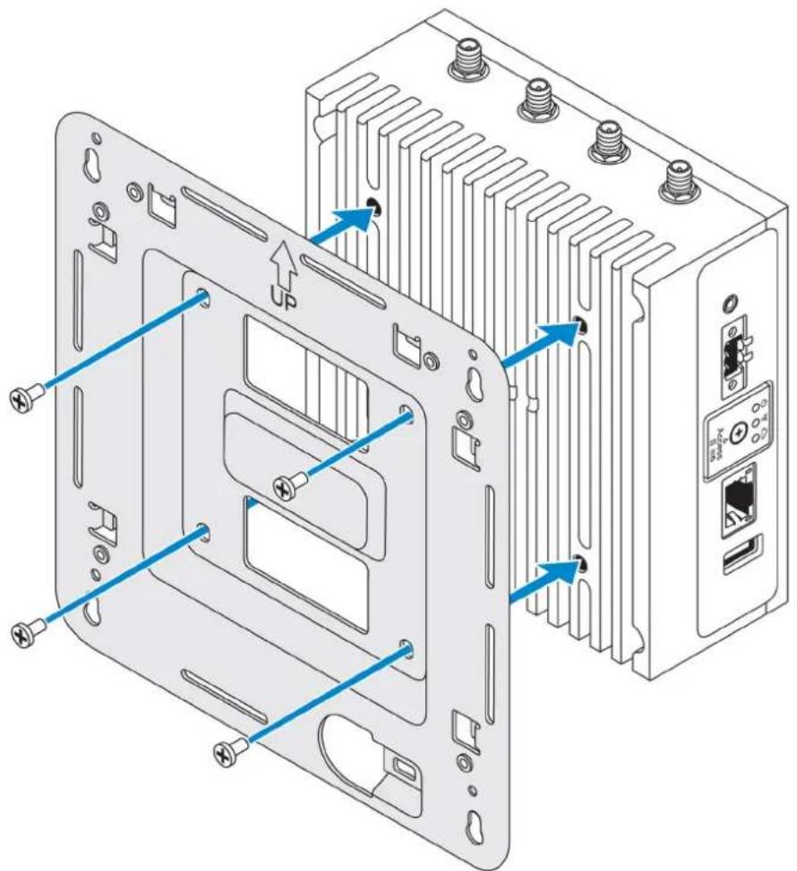
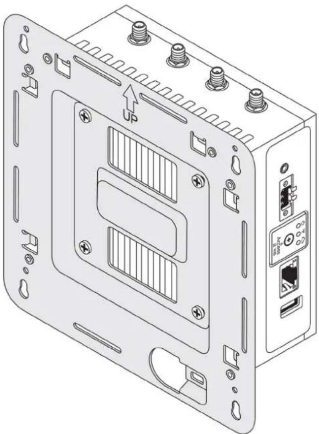
1 Secure the standard-mount bracket to the back of the Edge Gateway using the four M4x4.5 screws.
NOTE: Torque the screws at 8±0.5 kilograms-centimeter (17.64±1.1 pounds-inch).
natural_image
Technical diagram of an electronic device showing internal components and mounting points (no text or symbols present)2 Place the Edge Gateway against the wall, and align the holes in the standard-mount bracket with the holes on the wall. Screw holes on the bracket have a diameter of 3mm (0.12 in).
natural_image
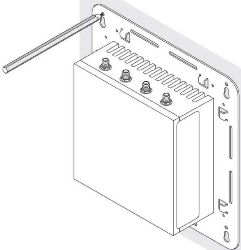
Technical line drawing of a device rear panel with mounting holes and internal slots (no text or symbols)3 Place the standard-mount bracket on the wall, and using the holes above the screw holes on the bracket, mark the positions to drill the four holes.
natural_image
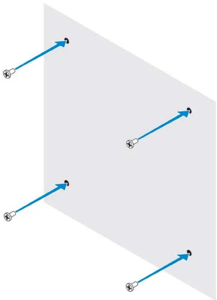
Technical line drawing of a rectangular electronic device with multiple screw holes and a handle (no text or symbols)4 Drill four holes in the wall as marked.
5 Insert and tighten four screws (not supplied) to the wall.
NOTE: Purchase screws that fit the diameter of the screw holes.
natural_image
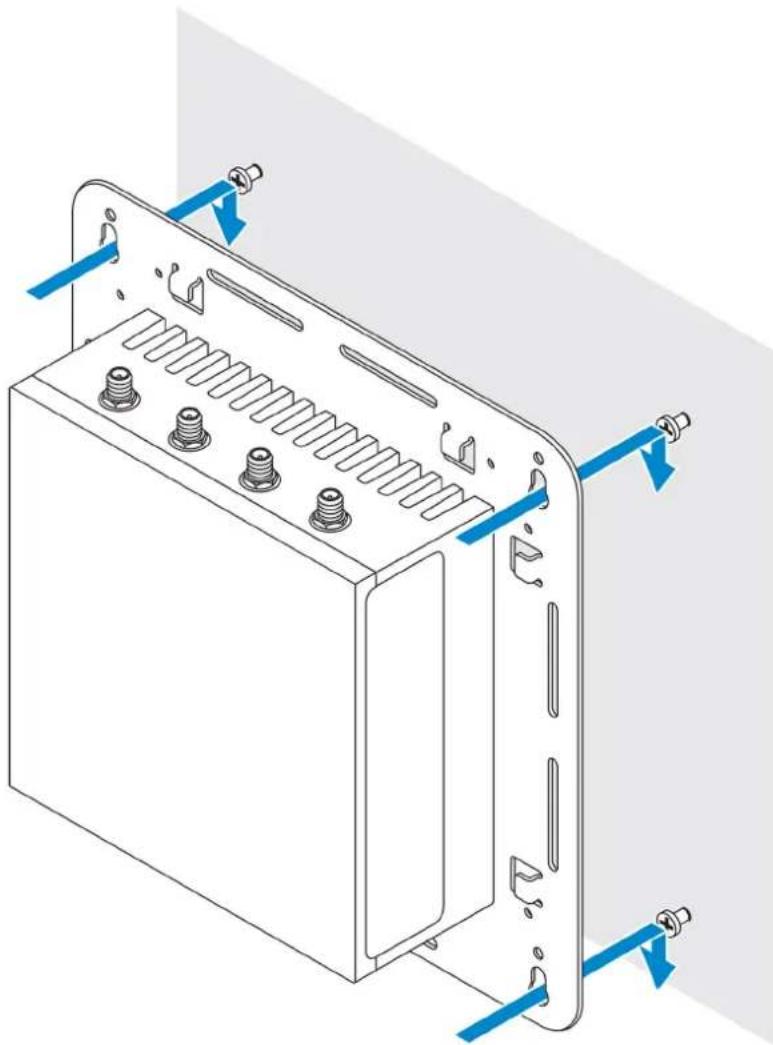
Diagram showing multiple blue arrows pointing toward a gray plane with no text or symbols6 Align the screw holes on the standard-mount bracket with the screws and place the Edge Gateway onto the wall.
natural_image
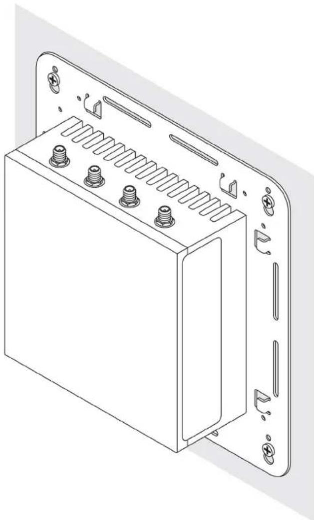
Technical line drawing of a battery pack with mounting holes and connectors (no text or symbols)7 Tighten the screws to secure the assembly to the wall.
natural_image
Technical line drawing of a rectangular electronic device with multiple screw holes and mounting brackets (no text or symbols)Mounting the Edge Gateway using quick-mount bracket
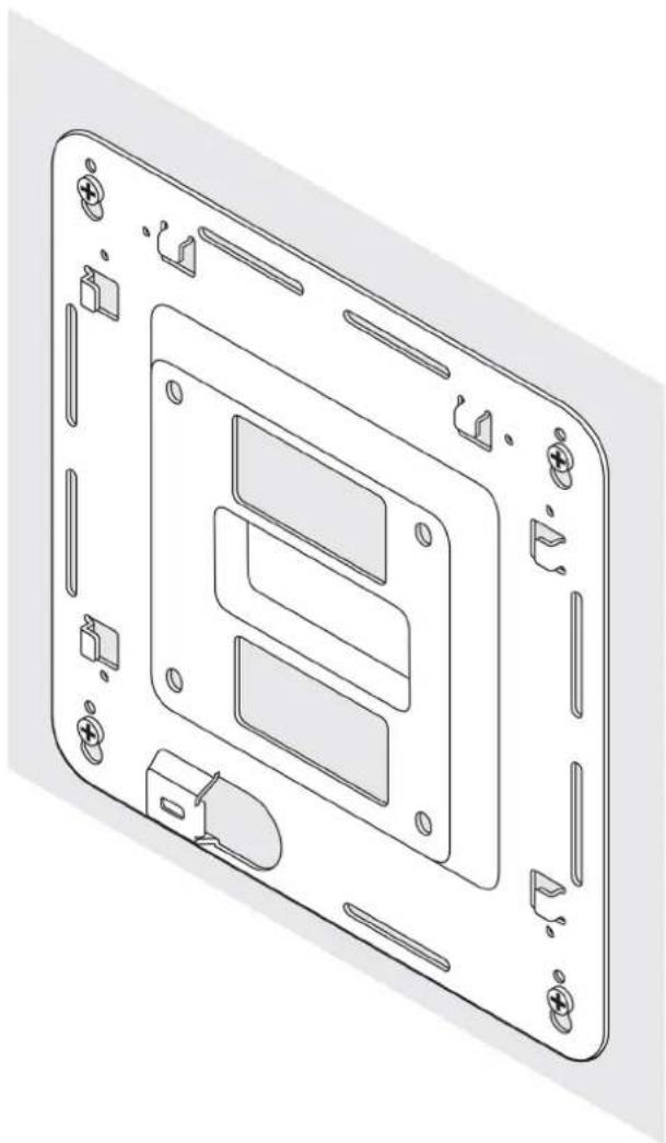
The quick-mount bracket is a combination of the standard-mount bracket and the DIN-rail bracket. It enables you to easily mount and demount the Edge Gateway.

NOTE The mounting brackets are shipped with only those screws required for securing the mounting brackets to the Edge Gateway.
Mounting dimensions
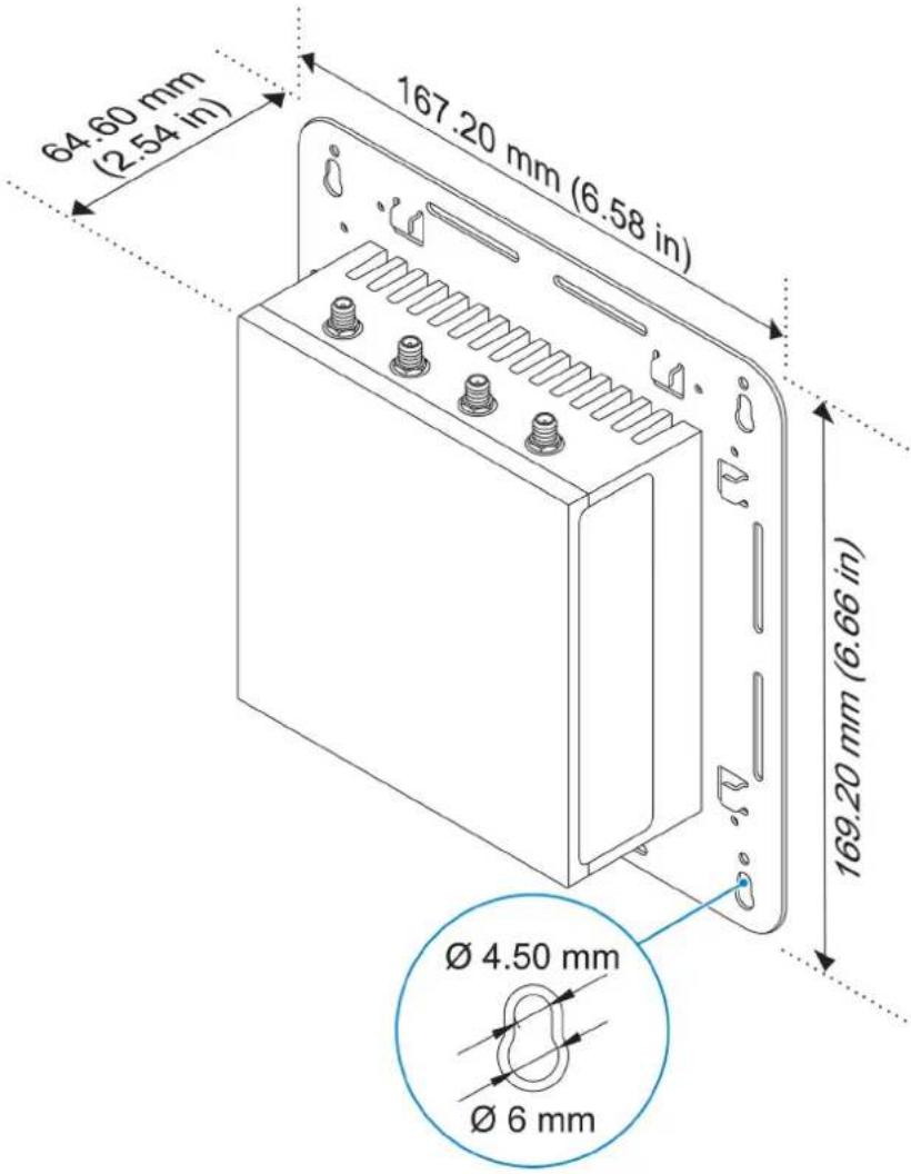
Mounting instructions
1 Place the standard-mount bracket on the wall, and using the holes above the screw holes on the bracket, mark the positions to drill the four holes.
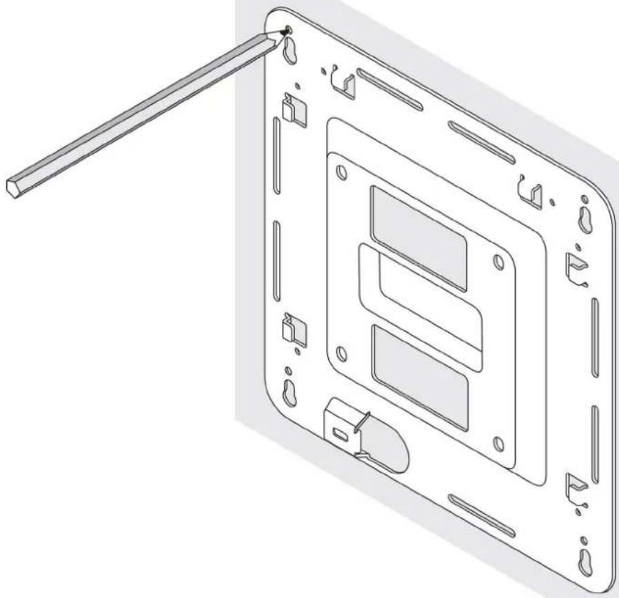
natural_image
Technical line drawing of a device casing with internal compartments and a rod inserted (no text or symbols)2 Drill four holes in the wall as marked.
3 Insert and tighten four screws (not supplied) to the wall.

NOTE: Purchase screws that fit the diameter of the screw holes.
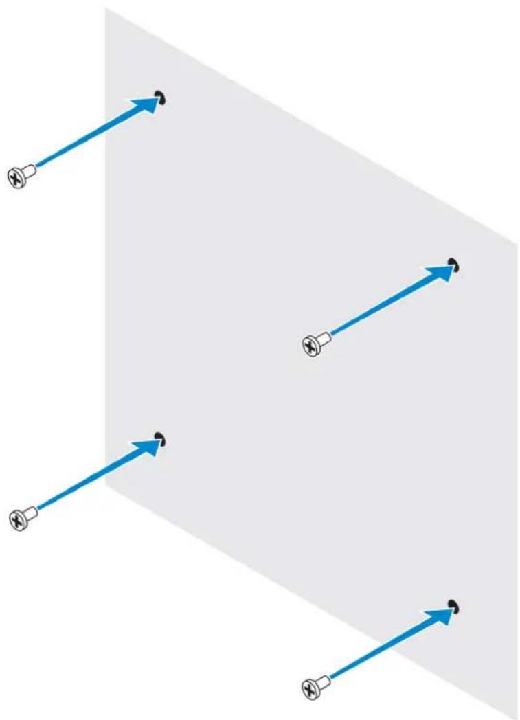
natural_image
Diagram showing multiple blue arrows pointing toward a gray plane with no text or symbols4 Align the screw holes on the standard-mount bracket with the screws on the wall, letting the bracket hang on the screws.
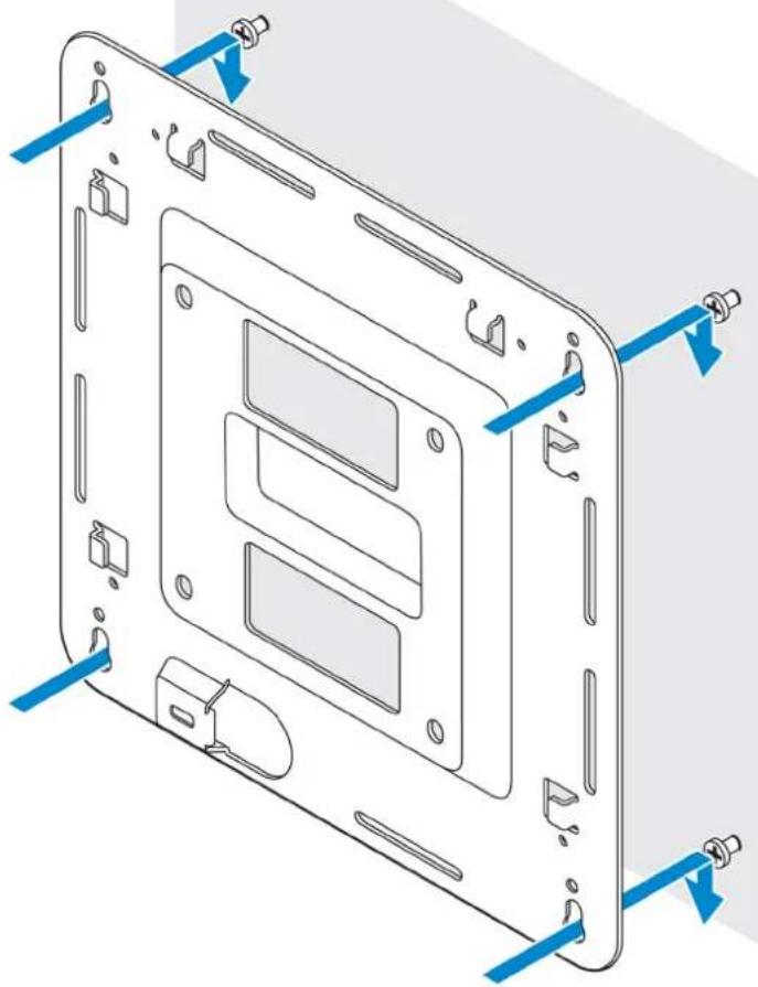
natural_image
Technical line drawing of a device casing with mounting holes and blue arrows indicating assembly or alignment (no text or symbols)5 Tighten the screws to secure the assembly to the wall.
natural_image
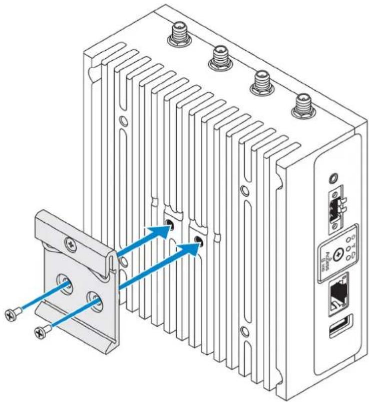
Exploded view diagram of a computer monitor base with internal components (no text or labels)6 Align the screw holes on the DIN-rail bracket with the screw holes at the back of the Edge Gateway.
7 Place the two M4x5 screws on the DIN-rail bracket and secure it to the Edge Gateway.
natural_image
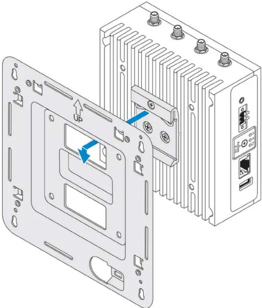
Technical line drawing of an industrial heat exchanger unit with cooling fins and mounting ports (no text or symbols)8 Place the Edge Gateway on the standard mount at an angle, and then pull the Edge Gateway down to compress the springs at the top of the DIN-rail bracket.
natural_image
Technical line drawing of an electronic device showing internal components and mounting points (no text or symbols)9 Push the Edge Gateway towards the DIN-rail to secure it on the standard-mount bracket.

NOTE: For more information about demounting the DIN-rail, see Demounting DIN rail.
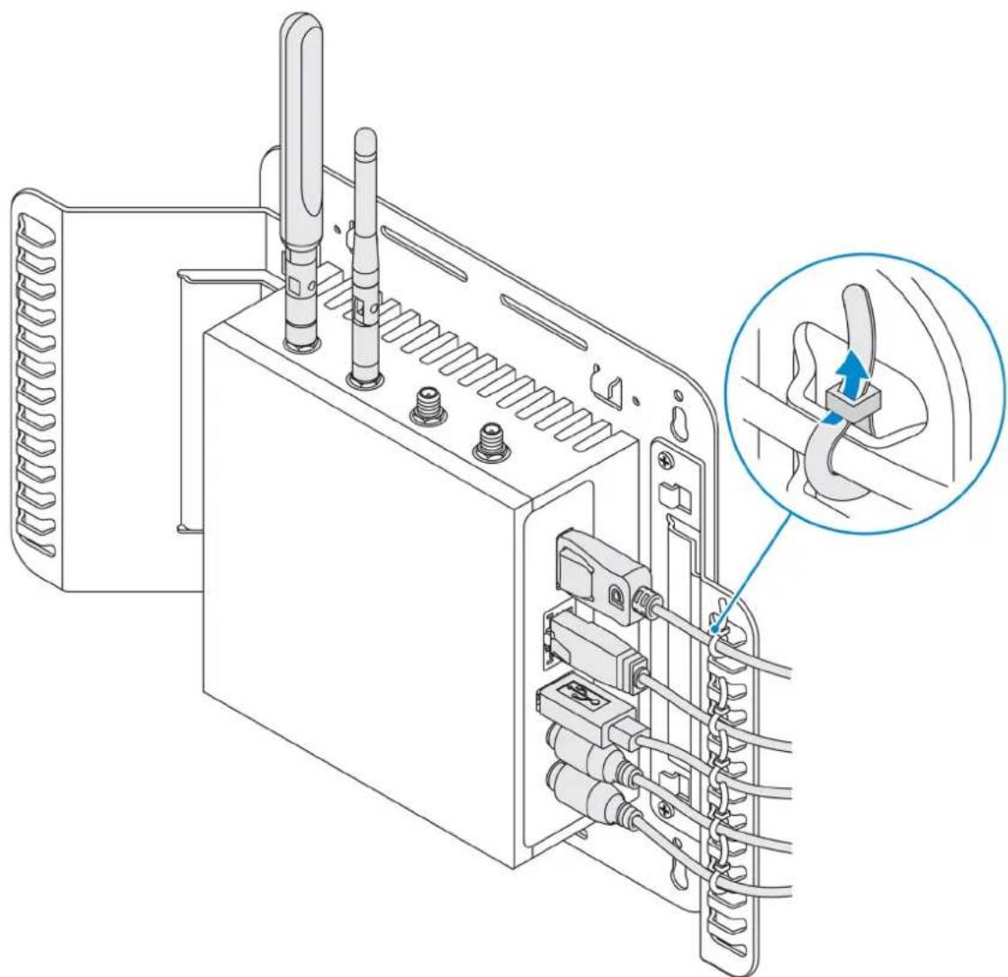
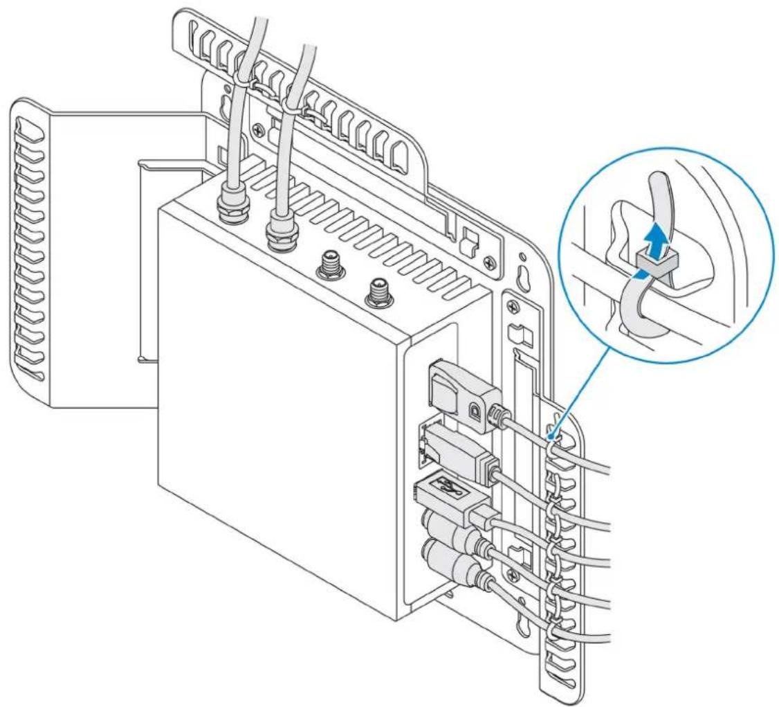
Attaching the cable control bars to the standard-mount bracket
1 Mount the Edge Gateway on the wall using the standard-mount bracket or quick-mount bracket.
2 Place the cable control bar on the mounting bracket and secure it to the notch.
△|CAUTION: Use the top cable control bar only with coaxial cable connections. Do not use with antennas.
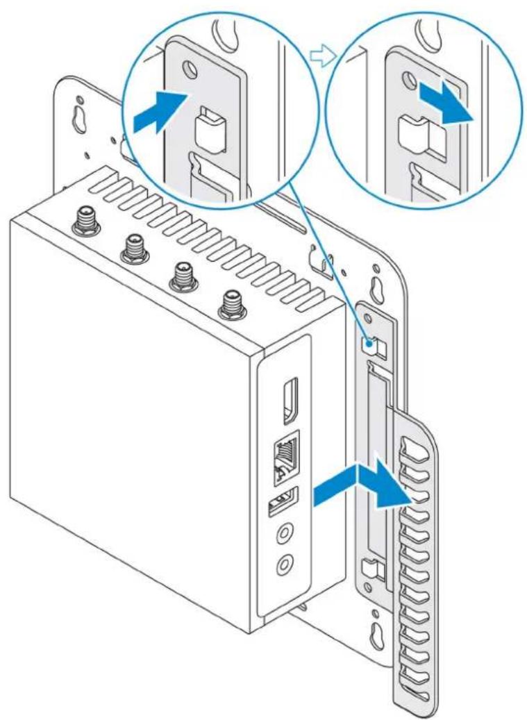
3 Align the screw holes on the cable control bar with the screw holes on the mounting bracket.
4 Tighten the six M3x3.5 mm screws that secure the cable control bar to the mounting bracket.
NOTE: Torque the screws at 5±0.5 kilograms-centimeter (11.02±1.1 pounds-inch).
natural_image
Technical line drawing of an electrical switchgear assembly with a magnified inset showing the cable connection (no text or symbols present)5 Connect the cables to the Edge Gateway.
6 Loop the cable lock (not supplied) to secure each cable to the cable control bar.
natural_image
Technical line drawing of a battery pack with attached cables and connectors, showing internal wiring and a magnified inset highlighting a cable connection (no text or symbols present)Mounting the Edge Gateway on a DIN rail using the DIN-rail bracket
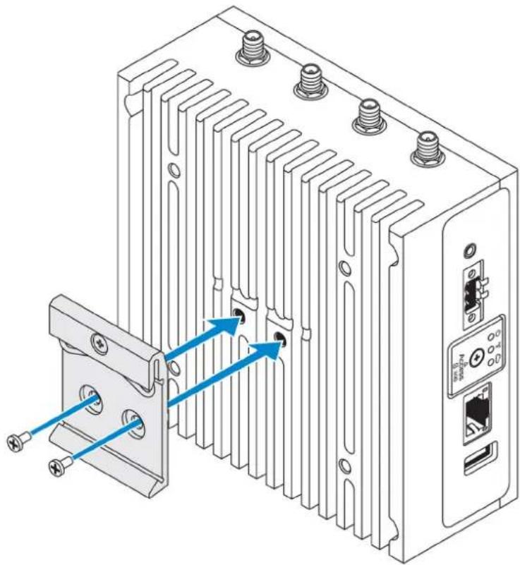
NOTE: The DIN-rail bracket includes the screws that are required for securing the bracket to the Edge Gateway.
1 Align the screw holes on the DIN-rail bracket with the screw holes at back of the Edge Gateway.
2 Place the two M4x5 screws on the DIN-rail bracket and secure it to the Edge Gateway.
natural_image
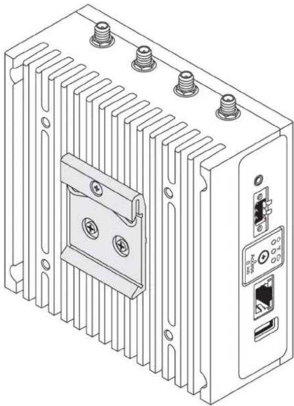
Technical line drawing of an industrial heat exchanger unit with cooling fins and mounting ports (no text or symbols)3 Secure the DIN-rail mounting bracket to the Edge Gateway using the two M4x5 screws provided.
NOTE: Torque the screws at 8±0.5 kilograms-centimeter (17.64±1.1 pounds-inch) on the DIN-rail mounting bracket.
natural_image
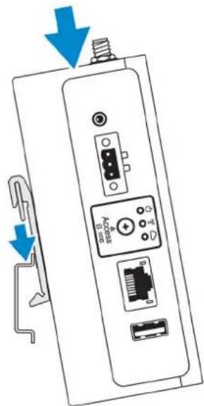
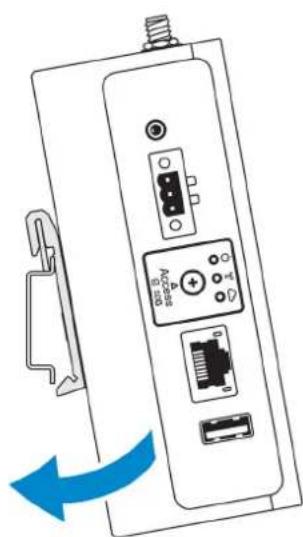
Technical line drawing of a heat exchanger or electronic device with cooling fins, screw holes, and an external ports (no text or symbols)4 Place the Edge Gateway on the DIN rail at an angle, and then pull the Edge Gateway down to compress the springs at the top of the DIN-rail mounting bracket.
5 Push the Edge Gateway towards the DIN-rail to secure the lower clip of the bracket onto the DIN rail.
natural_image
Diagram of a device with ports and connectors, showing a blue arrow indicating direction (no text or symbols present)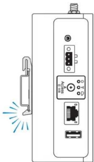
natural_image
Diagram of a device rear panel with ports and connectors, no text or symbols presentNOTE: For more information about demounting the DIN-rail, see Demounting DIN rail.
Mounting the Edge Gateway using the perpendicular mount
NOTE: The perpendicular mount is designed for mounting in a DIN-rail only.
NOTE: An open space of 63.50 mm (2.50 in) around the Edge Gateway is recommended for optimal air circulation. Ensure that the environmental temperature in which the Edge Gateway is installed does not exceed the operating temperature of the Edge Gateway. For more information about the operating temperature of the Edge Gateway, see the Edge Gateway Specifications.
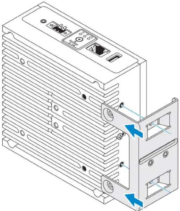
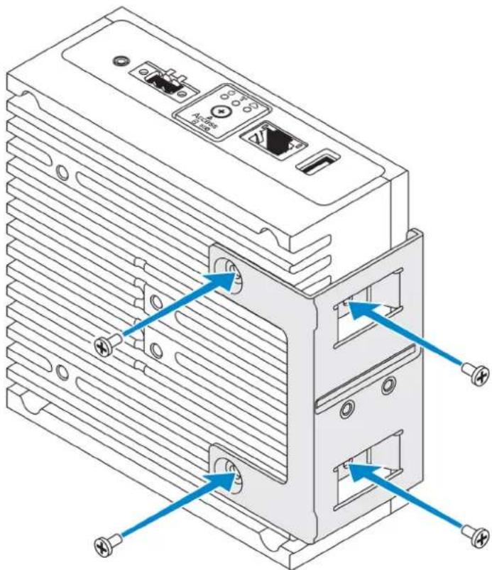
1 Align the screw holes on the perpendicular-mount bracket with the screw holes on the Edge Gateway.
natural_image
Technical line drawing of an electronic device showing internal components and a close-up view of the internal structure (no text or symbols)2 Tighten the four M4x7 screws to secure the Edge Gateway to the perpendicular-mount bracket.
NOTE: Torque the screws at 8±0.5 kilograms-centimeter (17.64±1.1 pounds-inch).
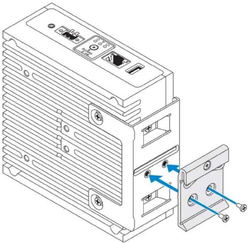
3 Align the screw holes on the DIN-rail mount bracket with the screw holes on the perpendicular-mount bracket, and tighten the two screws.
NOTE: Torque the screws at 8±0.5 kilograms-centimeter (17.64±1.1 pounds-inch).
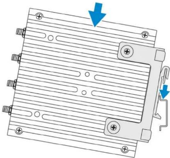
4 Place the Edge Gateway on the DIN rail at an angle and push the Edge Gateway down to compress the springs on the DIN-rail mount brackets.
natural_image
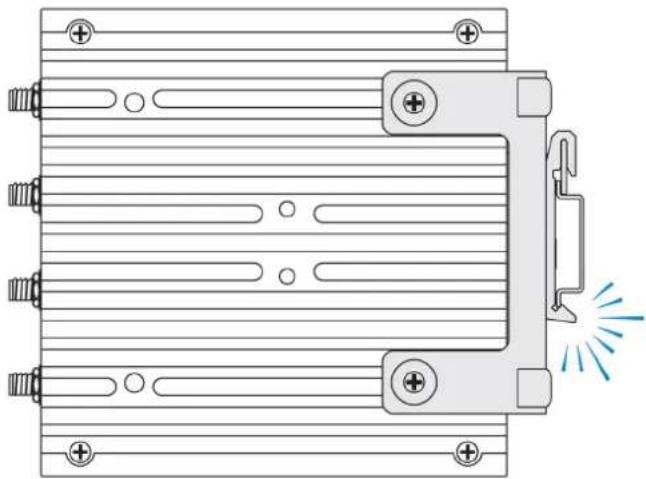
Technical diagram of a mechanical component with parallel grooves and mounting holes, showing no text or symbols.5 Push the Edge Gateway towards the DIN-rail to secure the lower clip of the bracket onto the DIN rail.
natural_image
Technical line drawing of a mechanical component with mounting holes and a highlighted section (no text or symbols)6 Secure the Edge Gateway on the DIN rail.
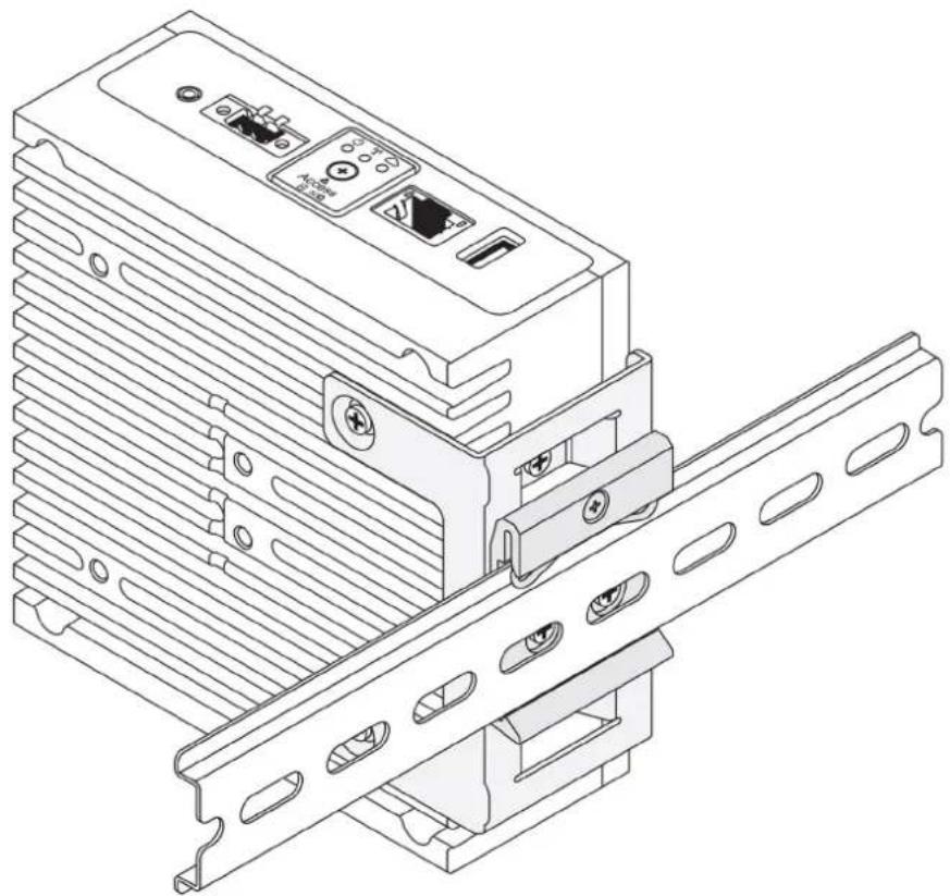
natural_image
Technical line drawing of a server rack with attached port and socket (no text or symbols)Mounting the Edge Gateway using a VESA mount
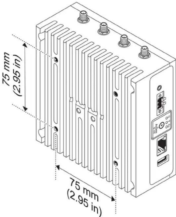
The Edge Gateway can be mounted on a standard VESA mount (75 mm x 75 mm).

NOTE: The VESA mount option is sold separately. For VESA mounting instructions, see the documentation that is shipped with the VESA mount.
Setting up the ZigBee dongle
CAUTION: Do not connect the ZigBee dongle if the Edge Gateway is installed inside the enclosure.
1 Power off your Edge Gateway.
2 Connect the ZigBee dongle to any external USB port on your Edge Gateway.
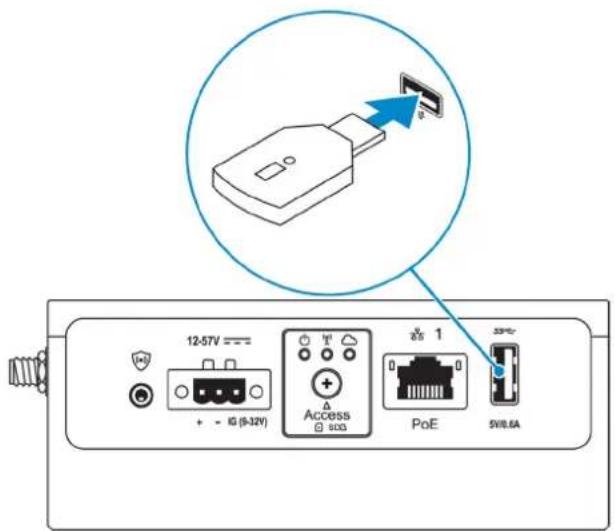
3 Power on your Edge Gateway and complete the setup.
NOTE: For more information about the ZigBee development, see www.silabs.com.
Setting up the operating system
CAUTION: To prevent operating system corruption from sudden power loss, use the operating system to gracefully shut down the Edge Gateway.
The Edge Gateway is shipped with one of the following operating systems:
• Windows 10 IoT Enterprise LTSB 2016
- Ubuntu Core 16
NOTE: For more information about Windows 10 operating system, see msdn.microsoft.com.
NOTE: For more information about the Ubuntu Core 16 operating system, see www.ubuntu.com/desktop/snappy.
Topics:
• Windows 10 IoT Enterprise LTSB 2016
- Ubuntu Core 16
- Ubuntu Server
- Creating the recovery USB flash drive
Windows 10 IoT Enterprise LTSB 2016
Boot up and login – Direct system configuration
1 Connect a monitor, keyboard and mouse to the Edge Gateway before you login.
2 Power on the Edge Gateway. At the first boot, you will not be prompted to enter login credentials. Subsequent boots will prompt for you to log in.
NOTE: The default user name and password are both admin.
Boot up and login—Static IP system configuration
NOTE: To help set up the Edge Gateway remotely, the static IP address of Ethernet port two on the Edge Gateway is set to these values at the factory:
· IP address: 192.168.2.1
- Subnet mask: 255.255.255.0
- DHCP server: Not applicable
You can connect your Edge Gateway to a Windows computer that is on the same subnet using a crossover cable.
1 On the Windows computer, search for View network connections in the control panel.
2 In the list of network devices displayed, right-click the Ethernet adaptor that you want to use to connect to the Edge Gateway, then click Properties.
3 On the Networking tab, click Internet Protocol Version 4 (TCP/IPv4) > Properties.
4 Select Use the following IP address, then enter 192.168.2.x (where x represents the last digit of the IP address, for example, 192.168.2.2).
NOTE: Do not set the IPv4 address to the same IP address as the Edge Gateway. Use an IP address between 192.168.2.2 to 192.168.2.254.
5 Enter the subnet mask 255.255.255.0, then click OK.
6 Secure a crossover network cable between Ethernet port two on the Edge Gateway and the configured Ethernet port on the computer.
7 On the Windows computer, launch Remote Desktop Connection.
8 Connect to the Edge Gateway using the IP address 192.168.2.1. The default username and password are both admin.
Restoring Windows 10 IoT Enterprise LTSB 2016
CAUTION: These steps will delete all the data on your Edge Gateway.
You can restore Windows 10 IoT Enterprise LTSB 2016 by using a USB flash drive.
Prerequisites
Create the recovery USB flash drive. For more information, see Creating the recovery USB flash drive.
Procedure
1 Connect the recovery USB flash drive to the Edge Gateway.
2 Power on the Edge Gateway.
The Edge Gateway will automatically boot from the USB recovery flash drive and restore Windows back to the factory image. Restoration takes about 25 minutes to complete and a confirmation log file is stored on the USB flash drive. Once restoration is complete, the system will power off.
NOTE: The confirmation log file is named
Windows 10 IOT Enterprise LTSB 2016 basic functions
BIOS update
Download BIOS updates for the Edge Gateway from www.dell.com/support. The download includes an executable file that may be run from the local machine. For more information about updating the BIOS, see Accessing and updating the BIOS.
Watchdog Timer
The Watchdog Timer for Windows 10 IoT Enterprise LTSB 2016 is controlled through the BIOS setting.
Enter the BIOS during boot by pressing F2.
The Watchdog Timer is enabled and disabled under the BIOS setting Watchdog Timer.
NOTE: For more information about BIOS settings on the Edge Gateway, see Default BIOS settings.
Cloud LED
NOTE: To utilize the Cloud LED, download the necessary tools and drivers from www.dell.com/support.
One unique feature of the Edge Gateway 3000 Series is the Cloud LED. Cloud LED enables you to visually inspect the operational status of the Edge Gateway by looking at the display light on the left panel of the Edge Gateway.
To enable this feature, you must expose and program a GPIO register on the Edge Gateway.
Follow these steps to control the Cloud LED on the Edge Gateway:
1 Download the Cloud LED utility from www.dell.com/support.
2 Extract the following files:
a DCSTL64.dll
b DCSTL64.sys
c DCSTL64.inf
d DCSTL64.cat
e CloudLED.exe
NOTE: These files must be in the same directory.
3 Run the CloudLED.exe from Command Prompt or PowerShell with administrative rights. Run the following commands:
- CloudLED.exe ON
- CloudLED.exe OFF
TPM support
Windows 10 IoT Enterprise LTSB 2016 supports TPM 2.0. For more information about TPM resources, see technet.microsoft.com/en-us/library/cc749022.
System shutdown and restart
Click Start > Power, and then click Restart or Shutdown to restart or shutdown the Edge Gateway, respectively.
LAN and WLAN network configuration
In the Search box, type Settings and open the Settings window. Select Network & Internet to configure the network.
Bluetooth configuration
In the Search box, type Settings and open the Settings window. Select Devices, and then select Bluetooth from the menu on the left panel to configure the network.
WWAN (5815) network configuration

NOTE: Ensure that the micro-SIM card is already activated by your service provider before using it in the Edge Gateway. For more information, see activate your mobile broadband service.
Follow these steps after installing the micro-SIM card:
1 In the Search box, type Settings and open the Settings window.
2 Select Network & Internet.
3 Locate the WWAN connection in the Wi-Fi section and select the entry to connect and disconnect from the WWAN adapter.
Ethernet configuration
1 In the Search box, type Settings and open the Settings window.
2 Select Network & Internet.
3 Select Ethernet, then Change adapter options to change Ethernet settings such as the duplex configuration.
Ubuntu Core 16
Overview
Ubuntu Core 16 is a Linux OS distribution that is an entirely new mechanism for managing IOT systems and its applications. For more information about Ubuntu Core 16 OS, see
• www.ubuntu.com/cloud/snappy
- www.ubuntu.com/internet-of-things
Prerequisites for setting up Ubuntu Core 16
Infrastructure
An active connection to the internet is needed to update the Ubuntu Core 16 operating system as well as applications (snaps).
Prior knowledge
- Ensure the personnel setting up Ubuntu Core 16 operating system has prior knowledge of the following:
- Unix/Linux commands
– Serial communication protocol - SSH terminal emulators (for example, PuTTY)
– Network settings (for example, proxy URL)
Boot up and log in – Direct system configuration
1 Power on the Edge Gateway. The system sets up the operating system automatically and restarts multiple times to apply all the configurations. The system takes approximately one minute to boot to the operating system.
2 When prompted, log in using the default credentials. The default user name and password are both admin. The default computer name is the service tag.
For example;
Ubuntu Core 16 on 127.0.0.1 (tty1)
localhost login: admin
Password: admin
Boot up and log in – Static IP system configuration
This allows you to connect your Edge Gateway through a host computer, which must be on the same subnet.
NOTE: The static IP address of Ethernet port two on the Edge Gateway is set to these values at the factory:
· IP address: 192.168.2.1
- Subnet mask: 255.255.255.0
- DHCP server: Not applicable
1 On the host computer, configure the Ethernet adaptor that is connected to the Edge Gateway with a static IPv4 address under the same subnet. Set the IPv4 address to 192.168.2.x (where x represents the last digit of the IP address, for example, 192.168.2.2).
NOTE: Do not set the IPv4 address to the same IP address as the Edge Gateway. Use an IP address between 192.168.2.2 to 192.168.2.254.
2 Set the subnet mask to 255.255.255.0.
Updating operating system and applications
After enabling the network connections and connecting to the internet, Dell recommends to have the latest OS components and applications installed. To update Ubuntu Core 16, run:
admin@localhost:\~\$ sudo snap refresh
Viewing operating system and application versions
Run the uname command to view system information:
root@DCPLB02:/sys/class/net# uname -a
Add the -a option at the end of the command to print all system information. For example:
Linux DCPLB02 4.4.0-98-generic #121-Ubuntu SMP Tue Oct 10 14:24:03 UTC 2017 x86_64 x86_64 x86 64 GNU/Linux
NOTE: Check if a newer version of the software is available. For more information on checking for updates, see Updating operating system and applications.
Additional Ubuntu commands
Basic commands
NOTE: For more information about Ubuntu commands, see https://snapcraft.io/.
Table 8. Basic commands
Action Ubuntu Core 16
| Viewing system attributes | #sudo snap version |
| Updating the image to the latest release | #sudo snap update |
| Viewing a list of all the snaps that are currently installed | #sudo snap find |
| Viewing a set and attribute to a snap | #sudo snap set |
| Querying attributes from a snap | #sudo snap get |
| Rebooting the system Run the command: | |
| admin@localhost:sudo reboot | |
| returns:System reboot successfully | |
| Shutting down the system Run the command: | |
| admin@localhost: sudo poweroffThe system shuts down successfully. | |
| Add a new user if libnss-extrausers is pre-installed | sudo adduser --extrausers testuser |
| Change a user's password | sudo passwd |
| Re-mount the Ubuntu Snappy 16 root-file system as read only | Snappy 16 rootfs is Read-Only |
| Accessing the built-in help | admin@localhost:~sudo snap --help |
| Listing the installed snaps | admin@localhost:~ sudo snap list |
| Updating the system name | admin@localhost:network-manager.nmcli generalhostname |
| Changing the time zone When the system arrives from the factory, the operating system is usually set to the UTC time zone.To change the time zone to your location, run the command:admin@localhost:~ sudo timedatectl --help | |
| Root-user credential Run the command: | |
| admin@localhost:sudo su - | |
| Returns: admin@localhost:~# sudo su -root@localhost:~# | |
| Identifying the System Service Tag Run the command: | |
| admin@localhost: cat /sys/class/dmi/id/product_serialThe system tag is printed. | |
| Identifying the system vendor Run the command: | |
| admin@localhost:$ cat /sys/class/dmi/id/board_vendor | |
| returnsDell Inc.The system tag is printed. | |
Ubuntu Network Manager
Network-Manager is a native Ubuntu Snappy connection manager. The application can be used to configure the Edge Gateway so that it's automatically-detected and connected to the network. The application can be used to configure multiple network devices.
A command-line utility nmcli is included with Network-Manager to support non-graphical user interface configurations.

NOTE: For more information about Network Manager, see https://wiki.archlinux.org/index.php/NetworkManager
Connecting through WWAN
NOTE: For more information on configuring and connecting through WWAN, see https://docs.ubuntu.com/core/en/stacks/network/network-manager/docs/configure-cellular-connections.
1 Check if a modem is present and identify the modem index number.
$ sudo modem-manager.mmcli -L
2 Check the modem status and identify the primary port.
$ sudo modem-manager.mmcli -m <x>
NOTE:
3 Create a profile.
$ sudo network-manager.nmcli c add con-name test type gsm ifname <primary port> apn internet
NOTE: Depending on the return results from step 2, replace
4 Check the WWAN status.
$ network-manager.nmcli r wwan
5 Turn on WWAN.
$ sudo network-manager.nmcli r wwan on
6 Find wwan0 in the interface list.
$ ifconfig -a
7 Enable the connection profile.
$ sudo network-manager.nmcli c up test
8 Check the Network Manager status.
$ network-manager.nmcli d
9 Disable the connection profile.
$ sudo network-manager.nmcli c down test
10 Check the Network Manager status.
$ network-manager.nmcli d
Connecting through WLAN
1 Show a list of network interfaces like eth0, eth1, wlan0, mlan0, and so on.
$ network-manager.nmcli d
2 Show a list of network interfaces like eth0, eth1, wlan0, mlan0, and so on.
$ network-manager.nmcli d
3 Show a list of available wireless access points.
$ network-manager.nmcli device wifi list
4 Wireless connection with nmcli: Run the following commands and replace \SSID, \PSK, and \$WIFI_INTERFACE with the variables for your environment.
- Connect:
sudo network-manager.nmcli dev wifi connectSSID password PSK ifnameWIFI_INTERFACE
- Disconnect:
sudo network-manager.nmcli dev disconnectWIFI_INTERFACE
Connecting through software-enabled Access Point (SoftAP)
This feature depends on the wireless module and its associated driver to function as a wireless-access point.

NOTE: For more information on SoftAP, see https://docs.ubuntu.com/core/en/stacks/network/wifi-ap/docs/index.
1 Login to Ubuntu Snappy. Make sure that the system is connected to the internet.
2 Run the command to find the application from the Ubuntu Snappy Store.
sudo snap seach wifi-ap
3 Run the command to install the application.
sudo snap install wifi-ap
4 After snap is installed, run the command to check the status.
\$ wifi-ap.status
5 Run the command to enable the access point and restart the service.
\$ wifi-ap.config set disabled=false
The Wi-Fi-AP default SSID Ubuntu is now visible to clients.
To secure the Wi-Fi access point with WPA 2 personal, change the following configuration items.
\$ wifi-ap.config set wifi.security=wpa2 wifi.security-passphrase=Test1234
The command enables WPA2 security with the passphrase set to Test1234.
Connecting through Bluetooth
This feature allows the system to connect to Bluetooth devices such as a Bluetooth keyboard.
1 Run the command to start bluetoothctl console.
bluetoothctl -a
The bluetoothctl console opens.
2 Run the command to power on the Bluetooth device.
\$power on
3 Register the agent for the keyboard:
\$agent KeyboardOnly
\$default-agent
4 Run the command to put the Bluetooth controller in pair-able mode.
\$pairable on
5 Run the command to scan for nearby Bluetooth devices.
\$scan on
6 Run the command to stop scanning after the Bluetooth keyboard is found.
\$scan off
7 Run the command to pair the Bluetooth keyboard.
\$pair
8 Enter the PIN code on the Bluetooth keyboard, if needed.
9 Run the command to trust the Bluetooth keyboard.
\$trust
10 Run the command to connect the to the Bluetooth keyboard.
\$connect
11 To quit the bluetoothctl console.
\$quit
Switching between WLAN and Bluetooth modes
1 Unload the WLAN/BT driver.
\$ modprobe -r ven_rsi_sdio
2 Adjust the mode in /etc/modprobe.d/rs9113.conf
3 Reload the WLAN/BT driver.
$ modprobe ven rsi sdio
4 Verify the operation mode. Refer to the table for operating mode values.
$ cat /sys/module/ven_rsi_sdio/parameters/dev_oper_mode
Table 9. Operating-mode values for WLAN and Bluetooth
| Operating mode value Wi-Fi station BT/BLE modes supported | softAP Clients supported by softAP | |
| 1 X N/A N/A | ||
| 1 N/A X 32 | ||
| 13 X Dual (BT classic and BTLE) | N/A | |
| 14 Dual (BT classic and BTLE) | X 4 | |
| 5 X BT Classic | N/A | |
| 6 | BT Classic | X 32 |
Bluetooth Serial Port Profile (SPP)
Assumptions for MAC addresses of each BT adapter:
BT MAC(MYCLIENT): XX:XX:XX:XX:XX:XX
BT MAC(MYSERVER): YY:YY:YY:YY:YY:YY
1 Pre-requirements (for Debian-only, not required on Ubuntu Core OS). sudo apt-get install bluez bluez-tools
2 Prepare to pair MYSERVER and MYCLIENT
$ sudo bluez.bluetoothctl -a
[bluetoothctl]# power on
[bluetooth]# discoverable on
[bluetooth]# scan on
[NEW] Device XX:XX:XX:XX:XX:XX MYCLIENT
[bluetooth]# scan off
3 Pair with each other. As of Bluetooth v2.1, Secure Simple Pairing is a requirement, and offers three methods of pairing devices, which are applicable on the Dell Gateway 3000 series:
- Just Works
- Numeric Comparison
• Passkey Entry
NOTE: For more information about bluetooth pairing, see https://blog.bluetooth.com/bluetooth-pairing-part-4.
[bluetooth]# agent on
[bluetooth]# default-agent
[bluetooth]# pairable on
[bluetooth]# pair XX:XX:XX:XX:XX:XX <MAC Address of Device to Pair>
[bluetooth]# connect XX:XX:XX:XX:XX:XX [CHG] Device XX:XX:XX:XX:XX:XX Connected: yes
[bluetooth]# exit
4 Configure SPP.
Server Device
$ bluez.sdptool add --channel=22 SP
$ ./rfcomm -r listen /dev/rfcomm0 22
Waiting for connection on channel 22
Connection from XX:XX:XX:XX:XX:XX to /dev/rfcomm0 <These lines will be seen when client comes>
Press CTRL-C for hangup
Then, create a new instance of terminal to screen the data over bluetooth serial.
$ cat /dev/rfcomm0
Client Device
$ bluez.sdptool add --channel=22 SP
$ ./rfcomm -r connect /dev/rfcomm0 YY:YY:YY:YY:YY:YY 22
Then, create a new instance of terminal to send data, for example, a new instance of ssh.
$ echo "test" > /dev/rfcomm0

NOTE: The rfcomm command is not available in this command. If required, you can copy the binary to the Edge Gateway from an AMD64-based system running Ubuntu 16.04 or above.
Security
Trusted Platform Module (TPM)
NOTE: For more information about the TPM, see https://developer.ubuntu.com/en/snappy/guides/security-whitepaper/.
TPM is only supported on devices that have TPM hardware installed on products with Snappy-enhanced security support. The TPM on/off setting is configurable in the BIOS and manageable in the operating system.
If TPM is turned off, the device node (/dev/tpm0) does not exist.
(plano)ubuntu@localhost:~$ ls /dev/tpm0
ls: cannot access /dev/tpm0: No such file or directory
If TPM is turned on, the device node (/dev/tpm0) exists.
(plano)ubuntu@localhost:~$ ls /dev/tpm0 /dev/tpm0
Watchdog Timer (WDT)
NOTE For more information about Watchdog Timer (WDT) commands, see www.sat.dundee.ac.uk/\~psc/watchdog/Linux-Watchdog.html.
Dell recommends that you enable the WDT by default to activate the fail-safe circuitry. Snappy, a WDT-compatible operating system, provides the capability to detect and recover the system from malfunctions or unexpected crashes.
To check daemon status, run the command:
admin@localhost:$ systemctl show | grep -i watchdog
Returns:
RuntimeWatchdogUSec=1min
ShutdownWatchdogUSec=10min
NOTE: The default value is 10. The actual value should be greater than 0.
To configure WDT, run the command:
admin@localhost:$ sudo vi /etc/systemd/system.conf.d/watchdog.conf
Cloud LED On/Off
1 To export Cloud LED PIN, run the command:
#sudo su -
#echo 346 > /sys/class/gpio/export
#echo out > /sys/class/gpio/gpio346/direction
2 To turn on Cloud LED, run the command:
#echo 1 > /sys/class/gpio/gpio346/value
or
To turn off Cloud LED, run the command:
#echo 0 > /sys/class/gpio/gpio346/value
Global Positioning Systems (GPS)
NOTE: For more information about GPS configurations, see http://locationd.readthedocs.io/en/latest/intro.html.
National Marine Electronics Association (NMEA) data is supported if the GPS module is present in the system. In the operating system, the location service is a central hub for multiplexing access to positioning subsystems available through hardware and software. It provides a client API offering positioning capabilities to applications and other system components..
To retrieve NMEA streaming data:
• Device node for NMEA streaming: Edge Gateway 3001/3003
$ cat /dev/ttyS4
To access location service:
$ sudo locationd.monitor
Enabled position/heading/velocity updates...
Update(Position(lat: 26.9511 deg, lon: 155.087 deg, alt: n/a, hor.acc.: n/a, ver.acc.: n/a), 1489044234694526189)
Update(0.552 m s^-1, 1489044234695698701)
Update(Position(lat: 26.9477 deg, lon: 155.098 deg, alt: n/a, hor.acc.: n/a, ver.acc.: n/a), 1489044234718316599)
Snappy auto update/Autopilot
Snappy auto update is a feature which runs in the background, ensuring that your software always up-to-date. We recommend that you enable the feature by default. The settings can be adjusted in the Ubuntu Core.
NOTE: For more information automatic updates, see https://docs.ubuntu.com/core/en/reference/automatic-refreshes.
Accessing Snappy Store/Snapweb
1 Enter ip_address: 4200 in a browser.

Your connection is not private
Attackers might be trying to steal your information from 192.168.43.102 (for example, passwords, messages, or credit cards). NET::ERR_CERT_AUTHORITY_INVALID

Automatically send some system information and page content to Google to help detect dangerous apps and sites. Privacy policy
ADVANCED
Back to safety
2 Select Advanced, then select proceed to the ip_address (unsafe).
3 Using the default login of 'admin', keeping the password blank, open Terminal and ssh remote login
lo@lo-latitude-E7470:\~\$ ssh admin@10.101.46.209 admin@10.101.46.209's password:
4 While running sudo snapweb.generate-token, copy the token.
lo@lo-latitude-E7470:\~\$ ssh admin@10.101.46.209 admin@10.101.46.209's password: Welcome to Ubuntu 16.04.1 LTS (GNU/Linux 4.4.0-45-generic x86_64)
* Documentation: https://help.ubuntu.com * Management: https://landscape.canonical.com * Support: https://ubuntu.com/advantage Welcome to Snappy Ubuntu Core, a transactionally updated Ubuntu.
* See https://ubuntu.com/snappy
It's a brave new world here in Snappy Ubuntu Core! This machine does not use apt-get or deb packages. Please see 'snap --hwlp' for app installation and transactional updates.
Last login: Tue Nov 01:10:12 2016 from 10.101.46.187 Admin@localhost:\~\$ sudo snapweb.generate-toen Snapweb Access Token:
GtYaoevIodhTgHDyFWczWtYkEhDYROpX0pf27K62TtTOVooUwRuQ) IgBB7ECznCP
Use the above token in the Snapweb interface to be granted access. admin@localhost:\~\$
5 Paste the token on the web page and click Submit.
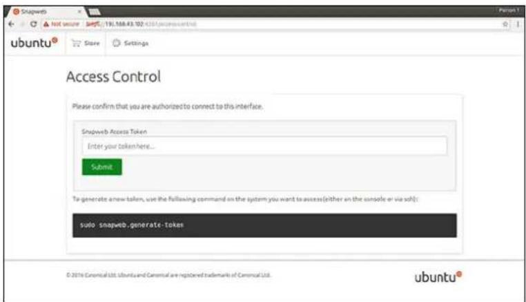
You can now access the snapweb.
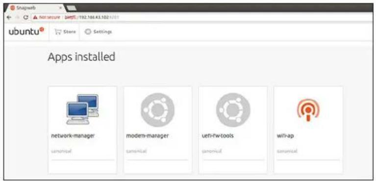
Sensors
The sensors on the Edge Gateway provide measurements on pressure, relative humidity and temperature, and motion.
Table 10. Sensor types
Relative humidity and temperature sensor ST Micro HTS221
Motion sensor—Accelerometer ST Micro LNG2DMTR
Pressure sensor ST Micro LPS22HB
Retrieve the raw data from the sensors by running the following commands. Then, apply the formula in the table to convert the data collected into measurements such as relative humidity and temperature.
Retrieving raw data from sensors
- To query sensor devices, run the command.
$ cat /sys/bus/iio/devices/iio:device*/name
hts221 <-- device0, Humidity and temp.
lng2dm_accel <-- device1, G-sensor
Ips22hb <-- device2, Pressure
• To retrieve data from the humidity and temperature sensor, run the command.
cat in_humidityrelative_offset
cat in_humidityrelative_raw
cat in_humidityrelative_scale
cat in_temp_offset
cat in_temp_raw
cat in_temp_scale
- To retrieve data from the motion sensor, run the command.
cat in_accel_scale_available
cat in_accel_*_scale
cat in_accel_*_raw
• To retrieve data from the pressure sensor, run the command.
$ cat in_pressure_raw
$ cat in_pressure_scale
Converting raw data for use
Apply the formula in the table to convert the raw data collected into usable measurements.
Table 11. Convert relative humidity and temperature sensor raw data
Relative humidity and temperature sensor ST Micro HTS221
RH (in %) = (in_humidityrelative_raw + in_humidityrelative_offset) * in_humidityrelative_scale
Temperature (degC) = (in_temp_raw + in_temp_offset) * in_temp_scale
Table 12. Convert motion sensor raw data
Motion sensor—Accelerometer ST Micro LNG2DMTR
accel_{x/y/z} (m/s^2) = in_accel_{x/y/z}_raw * in_accel_{x/y/z}_scale
Table 13. Convert pressure sensor raw data
Pressure sensor ST Micro LPS22HB
Pressure (hPa) = in_pressure_raw * in_pressure_scale * 10
Temperature (m degC) = in_temp_raw * in_temp_scale
Ignition Pin
The ignition pin can be used to wake the system from S3, S4, and S5 power states. The user can use the operating system power management to configure S3, S4, and S5 power states and shutdown.

NOTE: For more information about configuring the ignition pin (using the system.power-key-action command), see https://docs.ubuntu.com/core/en/reference/core-configuration.
Specify the action to take when the power button is pressed.
Table 14. Values and configuration options for the ignition pin
| ignore | Do nothing |
| poweroff (default) Shut down the system | |
| reboot | Reboot the system |
| halt | Halt the system |
| kexec | Direct-boot a new kernel |
| suspend | Suspend the system |
| hibernate | Hibernate the system |
| hybrid-sleep | Suspend to both disk and RAM |
| lock | Screen-lock all running sessions. |
For example, to reboot the system when the power button is pressed, run the command:
\$ snap set core system.power-key-action=reboot
System Power Management
Configuring low power states: S3 and S4
Configure sleep state-S3
\$ sudo systemctl suspend
Configure hibernate state-S4
\$ sudo systemctl hibernate
Rebooting or power off
To reboot the system
\$ sudo reboot
To power off
\$ sudo poweroff
Configuring system wake-up from LAN or WLAN
1 Enable Wake on LAN in the BIOS program. For more information on accessing the BIOS program, see Accessing BIOS settings
2 Connect the system to a wireless network.
\sudo network-manager.nmcli dev wifi connect \SSID password \$PSK ifname wlan0
3 Enable Wake on LAN.
\$ sudo iw phy0 wowlan enable magic-packet
4 Recheck the support status.
\$ sudo iw phy phy0 wowlan show
5 Make sure wlan0 is up and running with IP address.
6 Perform sleep.
\$ sudo systemctl sleep
Or, perform hibernation.
\$ sudo systemctl hibernate
7 Use another system to wake from wlan (Supported tools: wakeonlan, and etherwake).
\$ sudo wakeonlan MAC
\$ sudo etherwake MAC
Restoring Ubuntu Core 16
When the operating system is restored to the factory image, all data on the system is deleted. You can restore Ubuntu Core 16 operating system to the factory image using one of the following methods:
- Restore Ubuntu Core 16 from USB flash drive
- Restore Ubuntu Core 16 from the recovery partition on the Edge Gateway
– Option 1: Restoring from the operating system
– Option 2: Restoring during system POST
- Option 3: Restoring from boot menu (Edge Gateway 3003 only)
Option 1: Restoring from the operating system
CAUTION: These steps will delete all the data on your Edge Gateway
1 Connect the Edge Gateway remotely or through a KVM session.
2 Log in to the operating system.
3 Run the following command to trigger native eMMC recovery partition:.
sudo efibootmgr -n(efibootmgr | grep "factory_restore" | sed 's/Boot//g' | sed 's/[^0-9A-B]*///g') ; reboot
Option 2: Restoring during system POST
CAUTION: These steps delete all the data on your Edge Gateway.
1 Connect a USB keyboard to the Edge Gateway.
2 Power on the Edge Gateway.
The Power LED turns solid green while the Cloud LED is off.
3 During the first 20 seconds after applying power, press Ctrl+F repeatedly to trigger the operating system recovery.
4 When the Cloud LED starts blinking green, continue with one of these options:
NOTE: If the Cloud LED does not start blinking after 50 seconds, power off the Edge Gateway and repeat Steps 2 and 3.
Table 15. Start or cancel restoration during system POST
To start restoration To cancel restoration
- Press y, then press Enter.
The Cloud LED changes to solid green indicating that recovery is in progress. Once restoration is complete, the Cloud LED turns off and the system reboots. The restoration takes about 2 minutes to complete.
- Press n, then press Enter. Or, if the system does not detect any key-press within 30 seconds.
The Cloud LED turns off, and the system reboots.
Option 3: Restoring from boot menu
CAUTION: These steps will delete all the data on your Edge Gateway.
1 Connect a USB keyboard and display to the Edge Gateway.
2 Power on the Edge Gateway.
3 Press F12 when the Dell logo is displayed on the screen to enter the boot menu.
4 Select Factory Restore from the boot menu.
5 When you receive the message Factory Restore will delete all user data, are you sure? [Y/N], press Y.
Restore Ubuntu Core 16 from USB flash drive
CAUTION: These steps will delete all the data on your Edge Gateway.
Prerequisites
Create the recovery USB flash drive. For more information, see Creating the recovery USB flash drive.
Procedure
NOTE: For a video tutorial on how to restore Ubuntu Core 16 from a USB flash drive on the Edge Gateway 3003, click here.
1 Insert the USB flash drive into the USB port on the Edge Gateway.
2 Power on the Edge Gateway.
3 The Edge Gateway boots through the USB flash drive and flashes the Ubuntu Core installation image into storage automatically.
NOTE: When the installation images are being flashed to the storage, the Power LED is solid green and Cloud LED is blinking green.
4 The system powers off after the installation is complete.
NOTE: The installation takes about 3 minutes to complete.
5 Remove the USB drive after the Edge Gateway powers off.
6 Power on the Edge Gateway again to continue the installation. The system reboots several times during the installation and takes about 10 minutes to complete.
Once installation is complete, a login screen is displayed.
NOTE: On the Edge Gateway 3003, the login screen is displayed only if the display port is connected a monitor.
7 At the login screen, enter the default user name and password: admin.
The Edge Gateway is now ready for use.
NOTE: For more information about accessing Ubuntu on the Edge Gateway 3003 directly, see Boot up and log in—Direct system configuration.
Flashing a new OS image
Prerequisites
- A blank and FAT32—formatted USB flash drive with at least 4 GB of storage space
- Ubuntu Desktop ISO
NOTE: You can download the latest version of the Ubuntu Desktop ISO file from http://releases.ubuntu.com.
• A released Ubuntu Core 16 image from Dell.com/support:img.xz - LCD monitor
- USB keyboard
- USB mouse
- DisplayPort cable
- Ubuntu workstation with Ubuntu Desktop 14.04 or higher
Flashing new Ubuntu OS image
1 Insert a USB flash drive into the Ubuntu Desktop workstation.
2 Copy
3 Flash the installation image to USB flash drive.
a Start the Terminal application. It can be found by typing Terminal in the Unity Dash.
△|CAUTION: The dd command erases the content of the drive it writes to.
b Type the following command and press Enter.
xzcat <unique name-date>img.xz | sudo dd of=/dev/sda bs=32 ; sync
NOTE: The sda may have to be replaced with the actual name of the drive on the system.
4 Unmount and remove the USB flash drive.
5 Connect the power, keyboard, monitor, and Ethernet cable to your Edge Gateway.
6 Insert the USB flash drive into your Edge Gateway.
7 Power on and boot up the Edge Gateway from the USB flash drive.
The installation USB flash drive flashes the Ubuntu Core 16 installation image into storage automatically. After the installation is complete, the system shuts down.
8 Remove the USB flash drive.
9 Power on the system.
Ubuntu Core 16 is installed on your Edge Gateway.
Ubuntu Server
Overview
Ubuntu Server 18.04 is part of the larger set of Ubuntu products and is built on the Debian architecture. For more information about Ubuntu Server and Debian, see:
- ubuntu.com/server
• help.ubuntu.com/ - ubuntu.com/community/debian
Login to the Edge Gateway using Ethernet Port 1
These are the factory default settings:
- Username: admin
- Password: admin
• Network interface: eth0 - IPv4 method: auto
1 Access the dhcp server or setup the dhcp service as described in Installing or configuring Dynamic Host Configuration Protocol (DHCP) daemon.
2 Find the IP address assigned to the client Edge Gateway.
NOTE: The MAC ID is printed on the label of the Edge Gateway.
NOTE: The machine name is pre-configured and is the same as the Service Tag of the Edge Gateway.
3 Remote login via ssh session. For example:
# ssh admin@10.101.46.209
NOTE: 10.101.46.209 is an example, and should be replaced with the IP address obtained in step 2.
Installing or configuring Dynamic Host Configuration Protocol (DHCP) daemon
For more information about Dynamic Host Configuration Protocol (DHCP), see:
• help.ubuntu.com/lts/serverguide/dhcp.html.en
• help.ubuntu.com/community/isc-dhcp-server
Installing dhcpd
At a terminal prompt, enter the following command to install dhcpd:
<h1 id="sudo-apt-install-isc-dhcp-server">sudo apt install isc-dhcp-server</h1>
NOTE: You may need to edit /etc/default/isc-dhcp-server to specify the interfaces dhcpd should listen to.
NOTE: dhcpd diagnostic messages stored in the syslog.
Configuring dhcpd
1 Edit /etc/dhcp/dhcpd.conf, for example:
default-lease-time 600;
max-lease-time 7200;
subnet 192.168.1.0 netmask 255.255.255.0 {
range 192.168.1.150 192.168.1.200;
option routers 192.168.1.254;
option domain-name-servers 192.168.1.1, 192.168.1.2;
option domain-name "mydomain.example"; }
2 After changing the config file, restart the dhcpd.
<h1 id="sudo-systemctl-restart-isc-dhcp-serverservice">sudo systemctl restart isc-dhcp-server.service</h1>
3 Clients are found in the lease file.
<h1 id="cat-varlibdhcpdhcpdleases">cat /var/lib/dhcp/dhcpd.leases</h1>
Login to the Edge Gateway using Ethernet Port 2
These are the factory default settings:
- Username: admin
- Password: admin
• Network interface: eth1 - IPv4 method: manual
- IPv4 method: 192.168.2.1/24
1 Configure the system you will be using to connect the Edge Gateway with a static IPv4 address.
- The range for the static IPv4 address is 192.168.2.2 to 192.168.2.254.
- Set the subnet to 255.255.255.0.
2 Using an ethernet cable, connect the system with the Edge Gateway.
3 Remote login via ssh session. For example:
# ssh admin@192.168.2.1
Ubuntu Server driver information
This section contains information about Ubuntu Server 18.04 and supporting kernel, v4.15.x.
Table 16. Ubuntu Server drivers
Component Hardware module Interface Driver
| TPM Nuvoton NPCT650TB1YX LPC tpm_crb | |||
| RS232/RS422/RS485 Exar XR21V1412IL32TR + SP339EER1 | I2C xr_usb_serial_common | ||
| ADC/DAC/GPIO ADI AD5593R I2C ad5593r | |||
| Ethernet Realtek RTL8119I PCI-E r8169 | |||
| Audio | Realtek ALC5660 (ALC3277) | I2S | snd_soc_rt5660snd-soc-sst-bytcr-rt5660 |
| WLAN/BT/BLE | Redpine Signal RS9113 | SDIO | rsi_sdiorsi_91x |
| WWAN 4G LTE | Sierra MC-7455Sierra MC7430 | USB | cdc_mbim |
| WWAN 3G | Sierra MC-HL8548 | USB | cdc_mbim |
| Sensor: Pressure ST Micro LPS22HB | I2C st_pressure_i2c | ||
| Sensor: Relative humidity and temperature | ST Micro HTS221 | I2C hts221_i2c | |
| Sensor: 3-axis "femto" accelerometer | ST Micro LNG2DMTR | I2C st_accel_i2c | |
| WDT | iTCO | I2C | iTCO_wdtwdat_wdt |
Firmware management on Ubuntu Server
UEFI BIOS updates for Ubuntu Server will be released online through Linux Vendor Firmware Service (LVFS)-based methods, as described at fwupd.org.
The firmware capsule update is enabled by default. The fwupgmgr command and fwupd firmware update daemon are used to update the UEFI BIOS firmware, in compliance with LVFS requirements.
NOTE
For additional information on how to update the firmware under Linux, see en.community.dell.com/techcenter/b/techcenter/archive/2016/02/02/dell-firmware-updating-under-linux.
Ubuntu Server firmware update—Online method
Follow these steps to update the Ubuntu Server firmware automatically.
1 Detect all devices using the fwupd command.
# sudo fwupdmgr get-devices
2 Download the latest metadata from LVFS.
# sudo fwupdmgr refresh
3 If firmware updates are available for the Edge Gateway, get updates.
# sudo fwupdmgr get-updates
4 Download and apply all updates to the Edge Gateway.
# sudo fwupdmgr update -v
Updates that can be applied without having to reboot will be installed immediately.
5 If there are updates that need to be installed after rebooting, reboot the Edge Gateway.
# sudo reboot
Ubuntu Server firmware update—Manual method
Follow these steps to update the Ubuntu Server firmware manually.
Search for the Edge Gateway firmware.cab file at fwupd.org/lvfs/devicelist and copy it to the target device.
1 Display all devices detected by the fwupd command.
# sudo fwupdmgr get-devices
2 Install the downloaded firmware.cab file.
# sudo fwupdmgr [Installation path of firmware.cab] -v
3 Reboot the system to install the updates.
# sudo reboot
Configure Watchdog Timer (WDT)
We recommend to enable the WDT by default to activate the fail-safe circuitry.
For more information about WDT, see:
• msdn.microsoft.com/en-us/windows/hardware/gg463320
- lwn.net/Articles/701235/
Configuring Watchdog Timer (WDT)
We recommend to enable the WDT by default to activate the fail-safe circuitry.
1 Show the available WDT settings.
# cat /etc/watchdog.conf
NOTE: If watchdog-timeout=is set to a non-zero value, the watchdog hardware (/dev/watchdog or the path specified with WatchdogDevice=or the kernel option systemd.watchdog-device=) will be programmed to automatically reboot the system if it is not contacted within the specified timeout interval.
2 Show the WDT environmental settings.
# cat /etc/default/watchdog
Read-status through sysfs interface
Table 17. WDT file descriptions
Read-only file location Description
| /sys/class/watchdog/watchdog0/bootstatus | Contains status of the WDT device at boot. It is equivalent to WDIOC_GETBOOTSTATUS of input-output control (ioctl) interface. |
| /sys/class/watchdog/watchdog0/identity Contains identity string of WDT device. | |
| /sys/class/watchdog/watchdog0/nowayout | If the device supports nowayout while reading it provides a value of 1, otherwise it is 0. |
| /sys/class/watchdog/watchdog0/state Provides active/inactive status of WDT device. | |
| /sys/class/watchdog/watchdog0/status | Contains the internal status of the WDT device. It is equivalent to WDIOC_GETSTATUS of ioctl interface. |
| /sys/class/watchdog/watchdog0/timeleft | Contains value of time left for reset generation. It is equivalent to WDIOC_GETTIMELEFT of ioctl interface. |
| /sys/class/watchdog/watchdog0/timeout | Contains the current value of timeout. |
Trusted Platform Module (TPM)
NOTE: For more information about the TPM, see developer.ubuntu.com/en/snappy/guides/security-whitepaper/.
TPM hardware is installed on products with Snappy-enhanced security support. TPM is supported only on these devices that have the TPM hardware installed. The TPM on/off setting is configurable in the BIOS and manageable through the Dell Command | Configure application in the operating system.
1 Verify if the TPM module has been loaded.
(plano)ubuntu@localhost:~$ ls /dev/tpm0
ls: cannot access /dev/tpm0: No such file or directory
2 If TPM is turned on, the device node (/dev/tpm0) exists.
<h1 id="ls-devtpm0">ls /dev/tpm0</h1>
Activate TPM in Dell Command | Configure
Follow these steps to check TPM activation in the Dell Command | Configure application.
1 If not set, set the BIOS password.
<h1 id="cctk-setuppwdnew-bios-password">cctk --setuppwd=<new-BIOS-password></h1>
2 If not enabled, enable TPM.
<h1 id="cctk-tpmon">cctk --tpm=on</h1>
3 Reboot the system.
<h1 id="systemctl-reboot">systemctl reboot</h1>
4 Activate TPM.
<h1 id="cctk-tpmactivationactivate-valsetuppwdsetupppwd">cctk --tpmactivation=activate --valsetuppwd=<Setupppwd></h1>
5 Reboot the system.
<h1 id="systemctl-reboot-2">systemctl reboot</h1>
NOTE: Do not power off the system while it is rebooting.
6 Check whether TPM is active.
<h1 id="cctk-tpmactivation">cctk --tpmactivation</h1>
Cloud LED On/Off
1 To export Cloud LED PIN, run the command:
#sudo su -
#echo 346 > /sys/class/gpio/export
#echo out > /sys/class/gpio/gpio346/direction
2 To turn on Cloud LED, run the command:
#echo 1 > /sys/class/gpio/gpio346/value
or
To turn off Cloud LED, run the command:
#echo 0 > /sys/class/gpio/gpio346/value
Advanced Linux Sound Architecture (ALSA)
Advanced Linux Sound Architecture (ALSA) is part of the Linux kernel, which provides an Application Programming Interface (API) for sound card device drivers.
The following table lists ALSA utilities included with the Edge Gateway:
Table 18. ALSA utilities
Utilities Description
| alsactl Advanced controls for ALSA sound drivers | |
| alsaloop Create loopbacks between PCM capture and playback devices | |
| alsamixer ALSA Ncurses mixer | |
| alsaucm ALSA use-case manager | |
| amixer Command-line mixer | |
| amidi Read from and write to ALSA raw-MIDI ports | |
| aplay, arecord Command-line playback and recording | |
| aplaymidi, arecordmidi Command-line MIDI playback and recording | |
| aconnect, aseqnet, aseqdump | Command-line MIDI sequencer control |
| iecset Set or dump IEC958 status bits | |
| speaker-test Speaker test-tone generator | |
NOTE: For more information about ALSA on Ubuntu, see packages.ubuntu.com/bionic/alsa-utils.
Playback
The following shows an example of how to playback audio with ALSA.
1 List available devices (default: baytrailcraudio).
<h1 id="aplay-1">aplay -1</h1>
2 Playback.
<h1 id="aplay-usrsharesoundsalsafront-centerwmv">aplay /usr/share/sounds/alsa/Front Center.wmv</h1>
Recording
The following shows an example of how to record audio with ALSA.
1 List available devices (default: baytrailcraudio).
<h1 id="arecord-1">arecord -1</h1>
2 Record.
<h1 id="arecord-f-cd-t-wav-tmptestwav">arecord -f cd -t wav /tmp/test.wav</h1>
Global Positioning Systems (GPS)
NOTE: For more information about GPS configurations, see locationd.readthedocs.io/en/latest/intro.html.
National Marine Electronics Association (NMEA) data is supported if the GPS module is present in the system. In the operating system, the location service is a central hub for multiplexing access to positioning subsystems available through hardware and software. It provides a client API offering positioning capabilities to applications and other system components.
The following shows the GPS-hardware enumeration on Edge Gateways:
- Edge Gateway 3001: /dev/ttyHSO
- Edge Gateway 3002: /dev/ttyHS1
- Edge Gateway 3003: /dev/ttyHSO
Example of dumping NMEA streaming data (for Edge Gateway 3001/3003):
<h1 id="cat-devttyhs0">cat /dev/ttyHS0</h1>
NOTE: For more information about NMEA data, see gpsinformation.org/dale/nmea.
Sensors
The sensors on the Edge Gateway provide measurements on pressure, relative humidity and temperature, and motion.
Table 19. Sensor types
Sensor type Description
| ST Micro HTS221 Relative humidity and temperature sensor |
| ST Micro LNG2DMTR Motion G-sensor—Accelerometer |
| ST Micro LPS22HB Pressure sensor |
Retrieve the raw data from the sensors by running the following commands. Then, apply the formula in the table to convert the data collected into measurements such as relative humidity and temperature.
Retrieving raw data from sensors
• To query sensor devices, run the following command.
$ cat /sys/bus/iio/devices/iio:device*/name
hts221 <-- device0, Humidity and temp.
lng2dm_accel <-- device1, G-sensor
Ips22hb <-- device2, Pressure
- To retrieve data from the humidity and temperature sensor, run the following commands.
cat in_humidityrelative_offset
cat in_humidityrelative_raw
cat in_humidityrelative_scale
cat in_temp_offset
cat in_temp_raw
cat in_temp_scale
- To retrieve data from the motion G-sensor, run the following commands.
cat in_accel_scale available
cat in_accel_*_scale
cat in_accel_*_raw
- To retrieve data from the pressure sensor, run the following commands.
$ cat in_pressure_raw
$ cat in_pressure_scale
Converting raw data for use
Apply the formula in the table to convert the raw data collected into usable measurements.
Table 20. Convert relative humidity and temperature sensor raw data
Relative humidity and temperature sensor ST Micro HTS221
RH (in %) = (in_humidityrelative_raw + in_humidityrelative_offset) * in_humidityrelative_scale
Temperature (degC) = (in_temp_raw + in_temp_offset) * in_temp_scale
Table 21. Convert motion sensor raw data
Motion sensor—Accelerometer ST Micro LNG2DMTR
accel_{x/y/z} (m/s^2) = in_accel_{x/y/z}_raw × in_accel_{x/y/z}_scale
Table 22. Convert pressure sensor raw data
Pressure sensor ST Micro LPS22HB
Pressure (hPa) = in_pressure_raw * in_pressure_scale * 10
Temperature (m degC) = in_temp_raw * in_temp_scale
Ignition Pin
The ignition pin can be used to wake the Edge Gateway.
Table 23. System state behavior
System state Input signal goes active Input signal goes inactive
G3 No effectNo effect
S5 System transitions to S0 No effect
S4 System transitions to S0 No effect
S3 System transitions to S0 No effect
S0 No effectSystem transitions to S3, S4, or S5
Selecting and applying a power option
- Adjust the power event in systemd using the following command:
sudo vi /etc/systemd/logind.conf
- Set the HandlePowerKey variable to one of the following power options:
Table 24. Power options
Power option Description
| ignore | Do nothing |
| poweroff (default) Shut down the system | |
| reboot | Reboot the system |
| halt | Halt the system |
| kexec | Direct-boot to a new kernel |
| suspend | Suspend the system |
| hibernate | Hibernate the system |
| hybrid-sleep | Suspend to both disk and RAM |
| lock | Screen-lock all running sessions. |
NOTE: For more information about power options, see freedesktop.org/software/systemd/man/logind.conf.html.
- Enable the power option by rebooting the system.
# sudo reboot
System Power Management
Configuring low-power states: S3 and S4
Use the following command to configure suspend state-S3:
# sudo systemctl suspend
Use the following command to configure hibernate state-S4:
# sudo systemctl hibernate
NOTE: Hibernate state is not supported if secure-boot mode is enabled.
Configuring system wake-up from low-power states (S3/S4/S5)—WLAN
1 Enable Wake on WLAN in the BIOS program. For more information on accessing the BIOS program, see Accessing BIOS settings. Alternatively, use Dell Command | Configure.
<h1 id="sudo-optdelldcccctk-wakeonlanenablewakeonwlan">sudo /opt/dell/dcc/cctk --wakeonlan=enablewakeonwlan</h1>
2 Connect the system to a wireless network.
<h1 id="sudo-nmcli-dev-wifi-connect-ssid-password-psk-ifname-wlan0">sudo nmcli dev wifi connect SSID passwordPSK ifname wlan0</h1>
3 Enable Wake on WLAN.
<h1 id="sudo-iw-phy0-wowlan-enable-magic-packet">sudo iw phy0 wowlan enable magic-packet</h1>
4 Recheck the support status.
<h1 id="sudo-iw-phy-phy0-wowlan-show">sudo iw phy phy0 wowlan show</h1>
5 Make sure wlan0 is up and running with the assigned IP address.
6 Perform sleep.
<h1 id="sudo-systemctl-sleep">sudo systemctl sleep</h1>
Or, perform hibernation.
<h1 id="sudo-systemctl-hibernate">sudo systemctl hibernate</h1>
7 Use another system to wake from WLAN (Supported tools: wakeonlan and etherwake).
<h1 id="sudo-wakeonlan-mac">sudo wakeonlan MAC</h1>
<h1 id="sudo-etherwake-mac">sudo etherwake MAC</h1>
Configuring system wake-up from low-power states (S3/S4/S5)—Real-Time Clock (RTC)
1 Sync the time between the Edge Gateway and operating system:
(root)# hwclock --hctosys
2 Obtain the RTC timer sysfs:
(root)# ls -a /sys/class/rtc/rtc0
3 Clean-up the timer:
(root)# echo 0 > /sys/class/rtc/rtc0/wakealarm
4 For example, set the wake-up event for 60 seconds:
(root)# echo +60 > /sys/class/rtc/rtc0/wakealarm
5 For example, place the Edge Gateway in suspend mode:
(root)# systemctl suspend
If successful, the RTC will wake up the Edge Gateway in 60 seconds.
Configuring system wake-up from low-power states (S3/S4/S5)—LAN
1 Enable Wake on LAN in the BIOS program. For more information on accessing the BIOS program, see Accessing BIOS settings. Alternatively, use Dell Command | Configure.
<h1 id="sudo-optdelldcccctk-wakeonlanenable">sudo /opt/dell/dcc/cctk --wakeonlan=enable</h1>
2 Enable Wake on LAN in nmcli (enabled by default).
<h1 id="nmcli-c-show-wired-connection-1-grep-wake">nmcli c show "Wired connection 1" | grep wake</h1>
802-3-ethernet.wake-on-lan: magic
<h1 id="nmcli-c-show-wired-connection-2-grep-wake">nmcli c show "Wired connection 2" | grep wake</h1>
802-3-ethernet.wake-on-lan: magic
3 Make sure the ethernet connection is up and running with the assigned IP address.
4 Perform sleep.
<h1 id="sudo-systemctl-sleep-2">sudo systemctl sleep</h1>
Or, perform hibernation.
# sudo systemctl hibernate
5 Use another system to wake from LAN (Supported tools: wakeonlan and etherwake).
<h1 id="sudo-wakeonlan-mac-2">sudo wakeonlan MAC</h1>
<h1 id="sudo-etherwake-mac-2">sudo etherwake MAC</h1>
Ubuntu Network Manager
Network-Manager is a native Ubuntu Server connection manager. The application can be used to configure the Edge Gateway so that it is automatically-detected and connected to the network. The application can be used to configure multiple network devices.
A command-line utility nmcli is included with Network-Manager to support non-graphical user interface configurations.
NOTE: For more information about Network-Manager, see wiki.archlinux.org/index.php/NetworkManager.
Connecting through WWAN
NOTE: For more information on configuring and connecting through WWAN, see docs.ubuntu.com/core/en/stacks/network/network-manager/docs/configure-cellular-connections.
1 Check if a modem is present and identify the modem index number.
# sudo mmcli -L
2 Check the modem status and identify the primary port.
# sudo mmcli -m<0>
NOTE: <0> refers to the modem index number. Replace <0> with the modem index number after running the command at step 1.
3 Create a profile with the given primary port, for example, MBIM.
# sudo nmcli c add con-name test type gsm ifname cdc-wdm0 apn internet
4 Check the WWAN status.
# nmcli r wwan
5 Turn on WWAN.
# sudo nmcli r wwan on
6 Find wwan0 in the interface list.
# ifconfig -a
7 Enable the connection profile.
# sudo nmcli c up test
8 Check the Network Manager status.
\$ nmcli d
9 Disable the connection profile.
# sudo nmcli c down test
10 Check the Network Manager status.
\$ nmcli d
Enable debug mode for verbose logging
1 Adjust the systemd service.
# vi lib/systemd/system/ModemManager.service
2 Replace the line with the following:
ExecStart=/usr/sbin/ModemManager --debug --log-level=DEBUG
3 Re-initiate the service.
# systemctl daemon-reload
Connecting through WLAN
1 Show a list of network interfaces like eth0, eth1, wlan0, mlan0, and so on.
<h1 id="nmcli-d">nmcli d</h1>
2 Show a list of available wireless access points.
<h1 id="nmcli-d-wifi">nmcli d wifi</h1>
3 Wireless connection with nmcli: Run the following commands and replace \SSID, \PSK, and \$WIFI_INTERFACE with the variables for your environment.
- Connect:
<h1 id="sudo-network-managernmcli-dev-wifi-connect-ssid-password-psk-ifname-wifi_interface">sudo network-manager.nmcli dev wifi connect SSID passwordPSK ifname $WIFI_INTERFACE</h1>
- Disconnect:
<h1 id="sudo-network-managernmcli-dev-disconnect-wifi_interface">sudo network-manager.nmcli dev disconnect $WIFI_INTERFACE</h1>
Connecting through SoftAP (wifi-ap.snap)
Enabling the Software-enabled Access Point (SoftAP) can improve connectivity to wireless-access points by increasing available entropy and reducing the number of connection retries to clients.
NOTE: For more information on SoftAP, see docs.ubuntu.com/core/en/stacks/network/wifi-ap/docs/index.
1 Install haveged.
<h1 id="sudo-apt-install-haveged">sudo apt install haveged</h1>
2 Disable wpa_supplicant.
<h1 id="sudo-systemctl-stop-wpa_supplicantservice">sudo systemctl stop wpa_supplicant.service</h1>
<h1 id="sudo-systemctl-mask-wpa_supplicantservice">sudo systemctl mask wpa_supplicant.service</h1>
3 Detach from network manager.
<h1 id="sudo-nmcli-d-set-wlan0-managed-no">sudo nmcli d set wlan0 managed no</h1>
4 Install wifi-ap snap.
<h1 id="snap-install-wifi-ap">snap install wifi-ap</h1>
5 Configure settings.
<h1 id="sudo-wifi-apsetup-wizard">sudo wifi-ap.setup-wizard</h1>
6 Check the status.
<h1 id="sudo-wifi-apstatus">sudo wifi-ap.status</h1>
ap.active: true
Connecting through SoftAP (hostapd)
Enabling the Software-enabled Access Point (SoftAP) can improve connectivity to wireless-access points by increasing available entropy and reducing the number of connection retries to clients.
NOTE: For more information on SoftAP, see docs.ubuntu.com/core/en/stacks/network/wifi-ap/docs/index.
1 Install haveged.
<h1 id="sudo-apt-install-haveged-2">sudo apt install haveged</h1>
2 Create your own /etc/hostapd/hostapd.conf. For example:
auth_algs=1
beacon_int=50
channel=3
country_code=ES
disassoc_low_ack=1
driver=nl80211
hw_mode=g
ht_capab=
ieee80211d=1
ieee80211n=1
interface=wlan0
require_ht=0
rsn_pairwise=CCMP
ssid=TEST
wmm_enabled=1
wpa=2
wpa_key_mgmt=WPA-PSK
wpa_passphrase=00000000
3 Disable wpa supplicant.
<h1 id="sudo-systemctl-stop-wpa_supplicantservice-2">sudo systemctl stop wpa_supplicant.service</h1>
<h1 id="sudo-systemctl-mask-wpa_supplicantservice-2">sudo systemctl mask wpa_supplicant.service</h1>
4 Detach from network manager.
<h1 id="sudo-nmcli-d-set-wlan0-managed-no-2">sudo nmcli d set wlan0 managed no</h1>
5 Use hostapd to create an access point.
<h1 id="hostapd-etchostapdhostapdconf">hostapd /etc/hostapd/hostapd.conf</h1>
Connecting through Bluetooth
This feature allows the system to connect to Bluetooth devices such as a Bluetooth keyboard.
1 Run the command to start bluetoothctl console.
#bluetoothctl
The bluetoothctl console opens.
2 Run the following command to power on the Bluetooth device.
<h1 id="power-on">power on</h1>
3 Register the agent for the keyboard:
<h1 id="agent-keyboardonly">agent KeyboardOnly</h1>
<h1 id="default-agent">default-agent</h1>
4 Run the following command to put the Bluetooth controller in pairable mode.
<h1 id="pairable-on">pairable on</h1>
5 Run the following command to scan for nearby Bluetooth devices.
<h1 id="scan-on">scan on</h1>
6 Run the following command to stop scanning after the Bluetooth keyboard is found.
<h1 id="scan-off">scan off</h1>
7 Run the following command to pair the Bluetooth keyboard.
<h1 id="pair-mac-address-of-bluetooth-keyboard">pair <MAC address of Bluetooth keyboard></h1>
8 Enter the PIN code on the Bluetooth keyboard, if needed.
9 Run the following command to trust the Bluetooth keyboard.
<h1 id="trust-mac-address-of-bluetooth-keyboard">trust <MAC address of Bluetooth keyboard></h1>
10 Run the following command to connect to the Bluetooth keyboard.
<h1 id="connect-mac-address-of-bluetooth-keyboard">connect <MAC address of Bluetooth keyboard></h1>
11 Run the following command to quit the bluetoothctl console.
<h1 id="quit">quit</h1>
Switching between WLAN and Bluetooth modes
1 Adjust the mode from default 13 to 14 in /etc/modprobe.d/rs9113.conf.
<h1 id="options-rsi_sdio-dev_oper_mode14">options rsi_sdio dev_oper_mode=14</h1>
2 Verify the operation mode.
<h1 id="cat-sysmodulersi_sdioparametersdev_oper_mode">cat /sys/module/rsi_sdio/parameters/dev_oper_mode</h1>
Table 25. Operating-mode values for WLAN and Bluetooth
| Operating mode value | STA AP BT EDR BLE Clients supported | |
| 1 | X | |
| 1 X 32 | ||
| 4 | X | |
| 5 X X | ||
| 6 X X 32 | ||
| 8 | X | |
| 9 X X | ||
| 13 X X X | ||
| 14 | X X X 4 | |
Bluetooth Serial Port Profile (SPP)
Assumptions for MAC addresses of each BT adapter:
BT MAC(MYCLIENT): XX:XX:XX:XX:XX:XX
BT MAC(MYSERVER): YY:YY:YY:YY:YY:YY
1 Pre-requirements.
<h1 id="sudo-apt-get-install-bluez-bluez-tools">sudo apt-get install bluez bluez-tools</h1>
2 Prepare to pair MYSERVER and MYCLIENT.
<h1 id="sudo-bluetoothctl">sudo bluetoothctl</h1>
[bluetoothctl]# power on
[bluetooth]# discoverable on
[bluetooth]# scan on
[NEW] Device XX:XX:XX:XX:XX:XX MYCLIENT
[bluetooth]# scan off
3 Pair with each other.
[bluetooth]# agent on
[bluetooth]# default-agent
[bluetooth]# pairable on
[bluetooth]# pair XX:XX:XX:XX:XX:XX <MAC Address of Device to Pair>
[bluetooth]# connect XX:XX:XX:XX:XX:XX [CHG] Device XX:XX:XX:XX:XX:XX Connected: yes
[bluetooth]# exit
As of Bluetooth v2.1, SPP offers three methods of pairing devices, which are applicable on the Edge Gateway:
- Just Works
- Numeric Comparison
• Passkey Entry
NOTE: For more information about Bluetooth pairing, see blog.bluetooth.com/bluetooth-pairing-part-4.
4 Configure SPP.
Server Device
<h1 id="bluezsdptool-add-channel22-sp">bluez.sdptool add --channel=22 SP</h1>
<h1 id="rfcomm-r-listen-devrfcomm0-22">./rfcomm -r listen /dev/rfcomm0 22</h1>
Waiting for connection on channel 22
Connection from XX:XX:XX:XX:XX:XX to /dev/rfcomm0 <These lines will be seen when client comes>
Press CTRL-C for hangup
Then, create a new instance of terminal to screen the data over bluetooth serial.
$ cat /dev/rfcomm0
Client Device
<h1 id="bluezsdptool-add-channel22-sp-2">bluez.sdptool add --channel=22 SP</h1>
<h1 id="rfcomm-r-connect-devrfcomm0-yyyyyyyyyy-22">./rfcomm -r connect /dev/rfcomm0 YY:YY:YY:YY:YY 22</h1>
Then, create a new instance of terminal to send data, for example, a new instance of ssh.
<h1 id="echo-test-devrfcomm0">echo "test" > /dev/rfcomm0</h1>

NOTE: rfcomm is not available in this command. If required, you can copy the binary to the Edge Gateway from an AMD64-based system running Ubuntu 16.04 or above.
Restoring Ubuntu Server
You can restore Ubuntu Server using one of the recovery methods defined for Ubuntu Server. For more information, see Restoring Ubuntu Core 16.
Creating the recovery USB flash drive
Prerequisites:
- Service Tag of the Edge Gateway
• A Windows computer with administrator rights and at least 8 GB of available storage space to download the Dell ISO recovery image
• A blank USB flash drive with at least 8 GB of storage space. These steps delete all data on the USB flash drive.
• .NET Framework 4.5.2 or higher
1 Download and save the Dell ISO recovery image file from:
• For Windows: dell.com/support/home/us/en/19/drivers/osiso/win
- For Ubuntu: dell.com/support/home/us/en/19/drivers/osiso/linux
2 Download and install the Dell OS Recovery Tool on your computer.
3 Launch the Dell OS Recovery Tool.
4 Click Yes in the User Account Control prompt.
5 Connect the USB flash drive to the computer.
6 Click Browse and navigate to the location where the Dell ISO recovery image file is saved.
7 Select the Dell ISO recovery image file and click Open.
8 Click Start to begin creating the bootable USB recovery media.
9 Click Yes to continue.
10 Click OK to complete.
Accessing and updating BIOS
Topics:
- Accessing BIOS settings
- Updating BIOS
- Default BIOS settings
Accessing BIOS settings
Use Dell Command | Configure (DCC) to access BIOS settings
Dell Command | Configure (DCC) is a factory-installed application in the Edge Gateway that helps to configure the BIOS settings. It consists of a Command Line Interface (CLI) to configure various BIOS features. For more information about DCC, see www.dell.com/dellclientcommandsuitemanuals.
- On the connected computer running Windows, click Start > All Programs > Command Configure > Dell Command | Configure Wizard
- On the connected computer running Ubuntu Core, access Dell Command | Configure using the command dcc.cctk
For more information on how to use the Dell Command | Configure application, see the Dell Command | Configure Installation Guide and User's Guide at www.dell.com/dellclientcommandsuitemanuals.
For more information about BIOS settings on the Edge Gateway, see Default BIOS settings
Use Edge Device Manager (EDM) to access BIOS settings
Edge Device Manager (EDM) enables you to perform remote management and system configuration. By using the EDM cloud console, you can view and configure the BIOS settings. For more information about the EDM, see www.dell.com/support/home/us/en/19/product-support/product/wyse-cloud-client-manager/research.
Entering BIOS setup during POST
NOTE: These steps are applicable only to the Edge Gateway 3003.
1 Connect a display, keyboard and mouse to the system.
2 Power on the Edge Gateway.
3 During POST, when the Dell logo is displayed, watch for the F2 prompt to appear, and then press F2 immediately.
Updating BIOS
NOTE: Download the latest BIOS file from dell.com/support/home/us/en/19/product-support/product/dell-edge-gateway-3000-series/drivers/.
Select one of these options to update the BIOS on the Edge Gateway.
• Using the USB invocation script
NOTE: Dell recommends the use of the USB invocation script to update the BIOS.
- (Edge Gateway 3003 only) Flashing the BIOS from a USB flash drive
- Updating the BIOS on a Windows system
• Using UEFI capsule update on an Ubuntu system - Dell Command | Configure (DCC)
- Edge Device Manager (EDM)
Using the USB invocation script
The Edge Gateway 3000 Series come in headless configurations—that is, configurations without any video output. Certain basic system administration tasks traditionally accomplished by the BIOS Setup program are not possible without video. Hence, to perform these system administration tasks, Edge Gateways contain a facility for running an invocation script of BIOS commands from a USB flash drive.
For more information about USB invocation script, see the Edge Gateway USB script utility User's Guide at www.dell.com/support/home/us/en/19/product-support/product/dell-edge-gateway-3000-series/drivers/.
Flashing the BIOS from a USB flash drive
Prerequisites
• BIOS file. Download the file from www.dell.com/support.
- A blank USB 2.0 or 3.0 USB flash drive with at least 4 GB of storage space.
Follow these steps to update the BIOS:
1 Power off the Edge Gateway.
2 Copy the BIOS update file to a USB flash drive.
3 Insert the USB flash drive in one of the available USB ports on the Edge Gateway.
4 Power on the Edge Gateway.
5 Press F12 when the system is starting up to enter the one-time boot screen.
6 On the one-time boot screen, choose Flash the BIOS.
7 In the next screen, select the BIOS file on the USB flash drive.
8 Start the flash process.
Updating the BIOS on a Windows system
Follow these steps to update the BIOS:
1 After connecting to the Edge Gateway.
2 Go to www.dell.com/support.
3 Click Product support, enter the Service Tag of your system, and then click Submit.
NOTE: If you do not have the Service Tag, use the auto-detect feature or manually browse to your system model.
4 Click Drivers & downloads.
5 Select the operating system installed on your system.
6 Scroll down the page and expand BIOS.
7 Click Download to download the latest version of the BIOS for your system.
8 After the download is complete, navigate to the folder where you saved the BIOS file.
9 Double-click the BIOS update file icon and follow the instructions on the screen.
Using UEFI capsule update on an Ubuntu system
The fwupgmgr tool or commands are used to update the UEFI BIOS on the system. The UEFI BIOS for this platform is released through online Linux Vendor File System (LVFS) based methods
Dell recommends that you enable the UEFI Capsule update by default so that it is running in the background to keep the system BIOS up to date.
NOTE: For more information about fwupd commands, see www.fwupd.org/users.
Without an internet connection
1 Download the latest .cab file from secure-lvfs.rhcloud.com/lvfs/devicelist.
2 Check the current BIOS details.
\$ sudo uefi-fw-tools.fwupdmgr get-devices
3 Copy the firmware.cab file to /root/snap/uefi-fw-tools/common/ folder.
\$ sudo cp firmware.cab /root/snap/uefi-fw-tools/common/
4 Check the details of the BIOS from the .cab file.
\$ sudo uefi-fw-tools.fwupdmgr get-details [Full path of firmware.cab]
5 Apply the update.
\$ sudo uefi-fw-tools.fwupdmgr install [Full path of firmware.cab] -v
6 Restart the system.
\$ sudo reboot
With an internet connection
1 Connect and login to the Edge Gateway.
NOTE: Connect and login to the Edge Gateway with one these options: - Direct system configuration (only for Edge Gateway 3003) - Static IP configuration (only for Edge Gateway 3002 and 3003)
2 Check the current BIOS details.
\$sudo uefi-fw-tools.fwupdmgr get-devices
3 Check if the update is available from LVFS service.
\$sudo uefi-fw-tools.fwupdmgr refresh
4 Download the BIOS from the www.dell.com/support.
\$sudo uefi-fw-tools.fwupdmgr get-updates
5 Apply the update.
\$sudo uefi-fw-tools.fwupdmgr update -v
6 Restart the system.
\$ sudo reboot
Dell Command | Configure (DCC)
Use DCC to update and configure the BIOS settings.
For more information on how to use DCC, see the DCC Installation Guide and User's Guide at www.dell.com/dellclientcommandsuitemanuals.
For more information about BIOS settings on the Edge Gateway, see Default BIOS settings.
Edge Device Manager (EDM)
BIOS can be updated remotely through the EDM console connected to a remote system.
For more information about EDM, see www.dell.com/support/home/us/en/19/product-support/product/wyse-cloud-client-manager/research.
Default BIOS settings
General (BIOS level 1)
Table 26. General (BIOS level 1)
BIOS level 2 BIOS level 3 Item Default value
| System Information | System Information BIOS Version Not applicable | ||
| Service Tag Not applicable | |||
| Asset Tag Not applicable | |||
| Ownership Tag Not applicable | |||
| Manufacturing Date Not applicable | |||
| Ownership Date Not applicable | |||
| Express Service Code Not applicable | |||
| Memory Information Memory Installed Not applicable | |||
| Memory Available Not applicable | |||
| Memory Speed | Not applicable | ||
| Memory Channel Mode | Not applicable | ||
| Memory Technology | Not applicable | ||
| Processor Information | Processor Type | Not applicable | |
| Core Count Not applicable | |||
| Processor ID Not applicable | |||
| Current Clock Speed | Not applicable | ||
| Minimum Clock Speed | Not applicable | ||
| Maximum Clock Speed Not applicable | |||
| Processor L2 Cache Not applicable | |||
| Processor L3 Cache Not applicable | |||
| HT Capable Not applicable | |||
| 64-Bit Technology Not applicable | |||
| Device Information eMMC Drive Not applicable | |||
| Boot Sequence Boot Sequence Boot Sequence - Depends on | installed boot devices | Depends on installed boot devices | |
| Boot List option [Legacy/UEFI] UEFI | |||
| Advanced Boot Options | Advanced Boot Options | Enable Legacy Option ROMs [Enable/Disable] | Enabled |
| Date/Time | Date/Time | Date [MM/DD/YY] | Not applicable |
| Time [HH:MM:SS A/P] | Not applicable | ||
System configuration (BIOS level 1)
Table 27. Systemconfiguration (BIOS level 1)
BIOS level 2 BIOS level 3 Item Default value
| Integrated NIC | Integrated NIC | Enable UEFI Network Stack [Enable/Disable] | Enabled |
| [Disabled, Enabled, Enabled w/PXE] | Enabled w/PXE | ||
| Integrated NIC 2 | [Disabled, Enabled] | Enabled | |
| USB Configuration | USB Configuration | Enable Boot Support [Enable/Disable] | Enabled |
BIOS level 2 BIOS level 3 Item Default value
| Enable USB 3.0 Controller [Enable/Disable] | Enabled | |
| Enable USB Port1 [Enable/Disable] | Enabled | |
| Enable USB Port2 [Enable/Disable] | Enabled | |
| Audio Enable Audio [Enable/Disable] Enabled | ||
| Miscellaneous Devices Enable WWAN [Enable/Disable] Enabled | ||
| Enable WLAN/Bluetooth [Enable/Disable] | Enabled | |
| Enable Dedicated GPS Radio [Enable/Disable] | Enabled | |
| Enable MEMs Sensor [Enable/Disable] | Enabled | |
| Watchdog Timer Support Watchdog Timer Support Enable Watchdog Timer [Enable/Disable] | Disabled | |
Security (BIOS level 1)
Table 28. Security (BIOS level 1)
BIOS level 2 BIOS level 3 Item Default value
| Admin Password Admin Password Enter the old password Not Set | |||
| Enter the new password Not applicable | |||
| Confirm new password Not applicable | |||
| System Password System Password Enter the old password Not Set | |||
| Enter the new password Not applicable | |||
| Confirm new password Not applicable | |||
| Strong Password Strong Password Enable Strong Password | [Enable/Disable] | Disabled | |
| Password Configuration | Password Configuration | Admin Password Min | 4 |
| Admin Password Max | 32 | ||
| System Password Min | 4 | ||
| System Password Max | 32 | ||
| Password Bypass | Password Bypass | [Disabled/Reboot Bypass] | Disabled |
BIOS level 2 BIOS level 3 Item Default value
| Password Change Password Change Allow Non-Admin Password | Changes [Enable/Disable] | Enabled |
| UEFI Capsule Firmware Updates UEFI Capsule Firmware Updates | Enable UEFI Capsule Firmware Updates [Enable/Disable] | Enabled |
| TPM 2.0 Security TPM 2.0 Security TPM 2.0 Security [Enable/ | Disable] | Enabled |
| TPM On [Enable/Disable] Enabled | ||
| PPI Bypass for Enable Commands [Enable/Disable] | Disabled | |
| PPI Bypass for Disable Commands [Enable/Disable] | Disabled | |
| Attestation Enable [Enable/Disable] | Enabled | |
| Key Storage Enable [Enable/Disable] | Enabled | |
| SHA-256 [Enable/Disable] Enabled | ||
| Clear [Enable/Disable] Disabled | ||
| Computrace(R) Computrace(R) Deactivate/Disable/Activate Deactivate | ||
| Chassis Intrusion Chassis Intrusion [Disable/Enable/On-Silent] Disable | ||
| CPU XD Support CPU XD Support Enable CPU XD Support | [Enable/Disable] | Enabled |
| Admin Setup Lockout Admin Setup Lockout Enable Admin Setup Lockout | [Enable/Disable] | Disabled |
Secure boot (BIOS level 1)
Table 29. Secure boot (BIOS level 1)
BIOS level 2 BIOS level 3 Item Default value
| Secure Boot Enable | Secure Boot Enable | [Enable/Disable] | Disabled |
| Expert Key Management | Expert Key Management | Enable Custom Mode [Enable/Disable] | Disabled |
| Custom Mode Key Management{PK/KEK/db/dbx} | PK |
Performance (BIOS level 1)
Table 30. Performance (BIOS level 1)
BIOS level 2 BIOS level 3 Item Default value
| Inter SpeedStep Enable Intel SpeedStep [Enable/Disable] | Enabled |
| C-States Control C-States Control C-states [Enable/Disable] Enabled | |
| Limit CPUID Value Limit CPUID Value Enable CPUID Limit [Enable/Disable] | Disabled |
Power management (BIOS level 1)
Table 31. Power management (BIOS level 1)
BIOS level 2 BIOS level 3 Item Default value
| Auto On Time Auto On Time Time Selection: [HH:MM A/P] | Auto On Time (if Wake Period =0) | 12:00AM |
| Value Selection: [0-254] Auto-Wake Period (0-254 minutes) | 000 | |
| Day Selection: [Disabled/Every Day/Weekdays/Select Days] | Disabled | |
| Under [Select Days] when enabled [Sunday/Monday.../Saturday] | Not applicable | |
| Wake on LAN/WLAN Wake on LAN/WLAN [Disabled/LAN Only/WLAN only/LAN or WLAN] | Disabled | |
POST behavior (BIOS level 1)
Table 32. POST behavior (BIOS level 1)
BIOS level 2 BIOS level 3 Item Default value
| Numlock LED Numlock LED Enable Numlock LED [Enable/Disable] | Enabled |
| Keyboard Errors Keyboard Errors Enable Keyboard Error Detection[Enable/Disable] | Enabled |
| Fastboot Fastboot [Minimal/Thorough/Auto] Thorough |
BIOS level 2 BIOS level 3 Item Default value
| Extend BIOS POST Time Extend BIOS POST Time [0 seconds/5 seconds/10 seconds] | 0 seconds |
| Full Screen Logo Full Screen Logo Enable Full Screen Logo [Enable/Disable] | Disabled |
| Warnings and Errors Warnings and Errors [Prompt on Warnings and Errors/Continue on Warnings/Continue on Warnings and Errors] | Prompt on Warnings and Errors |
Virtualization support (BIOS level 1)
Table 33. Virtualization support (BIOS level 1)
BIOS level 2 BIOS level 3 Item Default value
| Virtualization Virtualization Enable Intel Virtualization | Technology [Enable/Disable] | Enabled |
Maintenance (BIOS level 1)
Table 34. Maintenance (BIOS level 1)
BIOS level 2 BIOS level 3 Item Default value
| Service Tag Service Tag, text | entry capability when blank | Not applicable |
| Asset Tag Asset Tag, text entry | capability | Not applicable |
| SERR Messages SERR Messages Enable SERR Messages [Enable/Disable] | Disable] | Enabled |
| BIOS Downgrade BIOS Downgrade Allow BIOS Downgrade [Enable/Disable] | Disable] | Enabled |
| Data Wipe Data Wipe Wipe on Next Boot [Enable/Disable] | Disable] | Disabled |
| BIOS Recovery BIOS Recovery BIOS Recovery from Hard Drive | [Enable/Disable] | Enabled |
System logs (BIOS level 1)
Table 35. System logs (BIOS level 1)
BIOS level 2 BIOS level 3 Item Default value
BIOS Events BIOS Events List of BIOS events with "Clear
Log" button to clear the log
Not applicable
References
In addition to the Installation and Operation Manual, you can see the following documents available at www.dell.com/support/manuals.
• Dell Edge Gateway Specifications
• Dell Edge Gateway Service Manual
- Dell SupportAssist For Dell OpenManage Essentials Quick Start Guide
- Dell Command | Configure User's Guide
• Dell Command | Configure Reference Guide
• Dell Command | Monitor User's Guide
• Dell Command | PowerShell Provider User's Guide
For more information on using Dell Data Protection | Encryption see the documentation for the software at www.dell.com/support/manuals.
Topics:
- Antenna specifications
- De-mounting from DIN-rail bracket
- Connecting to the Edge Gateway
Antenna specifications
The Edge Gateway is professionally-installed equipment. The Radio Frequency (RF) output power does not exceed the maximum limit allowed in the country of operation.

CAUTION: Unauthorized antennas, modifications, or attachments may damage the device and potentially violate international regulations.

NOTE: Use only the supplied or an approved replacement antenna.

NOTE: Modifications to the device or use of unauthorized antennas not expressly approved by Dell is the sole responsibility of the user, configurator or operator, who must reassess the equipment in accordance to all applicable international Safety, EMC, and RF standards.
The Dell-authorized antenna specifications are as follows:
- Mobile Broadband
- Main: Dipole
- LTE Auxiliary: PIFA
• GPS/WLAN/Zigbee: Monopole
The following tables provide the gain specifications for different antenna positions.
Table 36. Mobile broadband main antenna maximum gain (dBi)
Antenna position—Bent Antenna position—Straight
| Frequency (MHz) 3G (dBi) 4G (dBi) 3G (dBi) 4G (dBi) | ||||
| 704~806 | Not applicable | 2 | Not applicable | 1.7 |
| 824~894 1 1.4 2.1 2.1 | ||||
| 880~960 0.5 1.4 1.4 1.5 | ||||
| 1710~1880 3.2 4.2 1.9 3 | ||||
| 1850~1990 | 3.9 4.3 3.2 3.4 | |||
| 1920~2170 | 4 | 4.4 | 3.2 3.4 | |
Table 37. Mobile broadband auxiliary antenna maximum gain (dBi)
Antenna position—Bent Antenna position—Straight
| Frequency (MHz) 4G (dBi) 4G (dBi) |
| 704~806 0.6 1.9 |
| 824~894 -0.3 -0.1 |
| 880~960 -1.9 -2.5 |
| 1710~1880 2.3 2.0 |
| 1850~1990 3.6 3.2 |
| 1920~2170 3.6 3.2 |
Table 38. WLAN/GPS antenna maximum gain (dBi)
| Antenna position—Bent | Antenna position—Straight | |||
| Frequency (MHz) | GPS (dBi) | WLAN (dBi) | GPS (dBi) | WLAN (dBi) |
| 1561~1602 | 2.6 | Not applicable | 2.4 | Not applicable |
| 2400~2500 | Not applicable | 3.4 | Not applicable | 1.6 |
De-mounting from DIN-rail bracket
1 Pull the Edge Gateway down to release from DIN-rail bracket.
2 Lift the Edge Gateway bracket off the DIN rail.
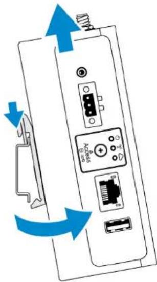
Connecting to the Edge Gateway
Windows 10 IoT Enterprise LTSB 2016
Boot up and login – Direct system configuration
1 Connect a monitor, keyboard and mouse to the Edge Gateway before you login.
2 Power on the Edge Gateway. At the first boot, you will not be prompted to enter login credentials. Subsequent boots will prompt for you to log in.
NOTE: The default user name and password are both admin.
Boot up and login—Static IP system configuration
NOTE: To help set up the Edge Gateway remotely, the static IP address of Ethernet port two on the Edge Gateway is set to these values at the factory:
• IP address: 192.168.2.1
- Subnet mask: 255.255.255.0
- DHCP server: Not applicable
You can connect your Edge Gateway to a Windows computer that is on the same subnet using a crossover cable.
1 On the Windows computer, search for View network connections in the control panel.
2 In the list of network devices displayed, right-click the Ethernet adaptor that you want to use to connect to the Edge Gateway, then click Properties.
3 On the Networking tab, click Internet Protocol Version 4 (TCP/IPv4) > Properties.
4 Select Use the following IP address, then enter 192.168.2.x (where x represents the last digit of the IP address, for example, 192.168.2.2).
NOTE: Do not set the IPv4 address to the same IP address as the Edge Gateway. Use an IP address between 192.168.2.2 to 192.168.2.254.
5 Enter the subnet mask 255.255.255.0, then click OK.
6 Secure a crossover network cable between Ethernet port two on the Edge Gateway and the configured Ethernet port on the computer.
7 On the Windows computer, launch Remote Desktop Connection.
8 Connect to the Edge Gateway using the IP address 192.168.2.1. The default username and password are both admin.
Ubuntu Core 16
Boot up and log in – Remote system configuration
1 Connect a network cable from Ethernet port one on the Edge Gateway to a DHCP-enabled network or router that provides IP addresses.
2 In your network's DHCP server, use the command dhcp-lease-list to obtain the IP address associated with the Edge Gateway's MAC address.
3 Setup as SSH session using an SSH terminal emulator (for example, native command-line ssh client on Linux or PuTTY on Windows).
NOTE: The SSH service is enabled on Ubuntu Core 16 by default.
4 Enter the command ssh admin@
For example;
lo@lo-Latitude-E7470:\~\$ ssh admin@10.101.46.209
admin@10.101.46.209's password:
Boot up and log in – Static IP system configuration
This allows you to connect your Edge Gateway through a host computer, which must be on the same subnet.
NOTE: The static IP address of Ethernet port two on the Edge Gateway is set to these values at the factory:
• IP address: 192.168.2.1
- Subnet mask: 255.255.255.0
- DHCP server: Not applicable
1 On the host computer, configure the Ethernet adaptor that is connected to the Edge Gateway with a static IPv4 address under the same subnet. Set the IPv4 address to 192.168.2.x (where x represents the last digit of the IP address, for example, 192.168.2.2).
NOTE: Do not set the IPv4 address to the same IP address as the Edge Gateway. Use an IP address between 192.168.2.2 to 192.168.2.254.
2 Set the subnet mask to 255.255.255.0.
Contacting Dell
To contact Dell for sales, technical assistance, or customer service issues:
1 Go to www.dell.com/contactdell.
2 Verify your country or region in the drop-down list at the bottom of the page.
3 Select the appropriate service or support link based on your requirement or choose the method of contacting Dell that is convenient for you.
Dell provides several online and telephone-based support and service options. Availability varies by country and product, and some services may not be available in your area.
NOTE: If you do not have an active internet connection, you can find the contact information on your purchase invoice, packing slip, bill, or Dell product catalog.

- Contents
- Overview....6
- System views....7
- Installing your Edge Gateway....12
- Setting up the ZigBee dongle....47
- Setting up the operating system....48
- Accessing and updating BIOS....80
- Overview
- System views
- Topics:
- Top view
- Bottom view
- Table 2. Bottom view
- Features
- Left view
- Table 3. Left view
- Right view
- Installing your Edge Gateway
- Safety and regulatory information
- Professional installation instructions
- Installation personnel
- Installation location
- External antenna
- Installation procedure
- Federal Communication Commission interference statement
- FCC caution:
- Industry Canada statement
- NOTE: Secondary enclosures are sold separately.
- Activating your mobile broadband service
- Windows operating system
- Ubuntu operating system
- Mounting your Edge Gateway
- Mounting the Edge Gateway using the standard-mount bracket
- Mounting the Edge Gateway using quick-mount bracket
- Mounting instructions
- Attaching the cable control bars to the standard-mount bracket
- Mounting the Edge Gateway on a DIN rail using the DIN-rail bracket
- Mounting the Edge Gateway using the perpendicular mount
- Mounting the Edge Gateway using a VESA mount
- Setting up the ZigBee dongle
- Setting up the operating system
- Windows 10 IoT Enterprise LTSB 2016
- Boot up and login – Direct system configuration
- Boot up and login—Static IP system configuration
- Restoring Windows 10 IoT Enterprise LTSB 2016
- Prerequisites
- Procedure
- Windows 10 IOT Enterprise LTSB 2016 basic functions
- BIOS update
- Watchdog Timer
- Cloud LED
- TPM support
- System shutdown and restart
- LAN and WLAN network configuration
- Bluetooth configuration
- WWAN (5815) network configuration
- Ethernet configuration
- Ubuntu Core 16
- Prerequisites for setting up Ubuntu Core 16
- Infrastructure
- Prior knowledge
- Boot up and log in – Direct system configuration
- Boot up and log in – Static IP system configuration
- Updating operating system and applications
- Viewing operating system and application versions
- Additional Ubuntu commands
- Basic commands
- Ubuntu Network Manager
- Connecting through WWAN
- Connecting through WLAN
- Connecting through software-enabled Access Point (SoftAP)
- sudo snap seach wifi-ap
- sudo snap install wifi-ap
- Connecting through Bluetooth
- bluetoothctl -a
- Switching between WLAN and Bluetooth modes
- Bluetooth Serial Port Profile (SPP)
- Security
- Trusted Platform Module (TPM)
- Watchdog Timer (WDT)
- Cloud LED On/Off
- Global Positioning Systems (GPS)
- Snappy auto update/Autopilot
- Accessing Snappy Store/Snapweb
- Your connection is not private
- Sensors
- Table 10. Sensor types
- Retrieving raw data from sensors
- Converting raw data for use
- Table 11. Convert relative humidity and temperature sensor raw data
- Table 12. Convert motion sensor raw data
- Table 13. Convert pressure sensor raw data
- Ignition Pin
- System Power Management
- Configuring low power states: S3 and S4
- Rebooting or power off
- Configuring system wake-up from LAN or WLAN
- Restoring Ubuntu Core 16
- Option 1: Restoring from the operating system
- CAUTION: These steps will delete all the data on your Edge Gateway
- Option 2: Restoring during system POST
- CAUTION: These steps delete all the data on your Edge Gateway.
- Option 3: Restoring from boot menu
- CAUTION: These steps will delete all the data on your Edge Gateway.
- Restore Ubuntu Core 16 from USB flash drive
- Flashing a new OS image
- Flashing new Ubuntu OS image
- Ubuntu Server
- Login to the Edge Gateway using Ethernet Port 1
- Installing or configuring Dynamic Host Configuration Protocol (DHCP) daemon
- Installing dhcpd
- Configuring dhcpd
- Login to the Edge Gateway using Ethernet Port 2
- Ubuntu Server driver information
- Firmware management on Ubuntu Server
- NOTE
- Ubuntu Server firmware update—Online method
- Ubuntu Server firmware update—Manual method
- Configure Watchdog Timer (WDT)
- Configuring Watchdog Timer (WDT)
- Read-status through sysfs interface
- Activate TPM in Dell Command | Configure
- Advanced Linux Sound Architecture (ALSA)
- Playback
- Recording
- Table 20. Convert relative humidity and temperature sensor raw data
- Table 21. Convert motion sensor raw data
- Table 22. Convert pressure sensor raw data
- Table 23. System state behavior
- Selecting and applying a power option
- sudo vi /etc/systemd/logind.conf
- Configuring low-power states: S3 and S4
- Configuring system wake-up from low-power states (S3/S4/S5)—WLAN
- Configuring system wake-up from low-power states (S3/S4/S5)—Real-Time Clock (RTC)
- Configuring system wake-up from low-power states (S3/S4/S5)—LAN
- Enable debug mode for verbose logging
- Connecting through SoftAP (wifi-ap.snap)
- Connecting through SoftAP (hostapd)
- Server Device
- Client Device
- Restoring Ubuntu Server
- Creating the recovery USB flash drive
- Prerequisites:
- Accessing and updating BIOS
- Accessing BIOS settings
- Use Dell Command | Configure (DCC) to access BIOS settings
- Use Edge Device Manager (EDM) to access BIOS settings
- Entering BIOS setup during POST
- Updating BIOS
- Using the USB invocation script
- Flashing the BIOS from a USB flash drive
- Updating the BIOS on a Windows system
- Using UEFI capsule update on an Ubuntu system
- Without an internet connection
- With an internet connection
- Dell Command | Configure (DCC)
- Edge Device Manager (EDM)
- Default BIOS settings
- General (BIOS level 1)
- System configuration (BIOS level 1)
- Security (BIOS level 1)
- Secure boot (BIOS level 1)
- Performance (BIOS level 1)
- Power management (BIOS level 1)
- POST behavior (BIOS level 1)
- Virtualization support (BIOS level 1)
- Maintenance (BIOS level 1)
- System logs (BIOS level 1)
- References
- Antenna specifications
- De-mounting from DIN-rail bracket
- Connecting to the Edge Gateway
- Boot up and log in – Remote system configuration
- Contacting Dell
Brand : DELL
Model : Edge Gateway 3003
Category : Uncategorized