
CT 20 - Tiller HUSQVARNA - Free user manual and instructions
Find the device manual for free CT 20 HUSQVARNA in PDF.
| Product Type | Tiller |
| Brand | HUSQVARNA |
| Model | CT 20 |
| Engine | Tecumseh TC III (2-stroke) |
| Working Width | 15.24 cm (6 in) or 25.4 cm (10 in) |
| Tine Speed | 162 rpm |
| Transmission | Worm gear |
| Weight | Approximately 11.34 kg (25 lb) |
| Number of Tines | 4 (removable) |
| Transport Kit | Included (wheel) |
| Ignition | On/Off switch |
| Handlebar | Reinforced with anti-vibration handles |
| Fuel | Gas/oil mixture 24:1 (2-stroke oil) |
| Transmission Lubrication | Every 100 hours of use |
| Spark Plug | Champion RCJ8Y (gap 0.76 mm) |
| Air Filter Maintenance | Every 3 months or 25 hours |
| Carburetor Adjustment | Idle adjustment screw |
| Safety Precautions | Stop engine before clearing, wear safety goggles |
| Warranty | Limited warranty (see manual) |
| Spare Parts | Available through an authorized dealer |
| Repairability | Repairable by a professional |
Frequently Asked Questions - CT 20 HUSQVARNA
User questions about CT 20 HUSQVARNA
0 question about this device. Answer the ones you know or ask your own.
Ask a new question about this device
Download the instructions for your Tiller in PDF format for free! Find your manual CT 20 - HUSQVARNA and take your electronic device back in hand. On this page are published all the documents necessary for the use of your device. CT 20 by HUSQVARNA.
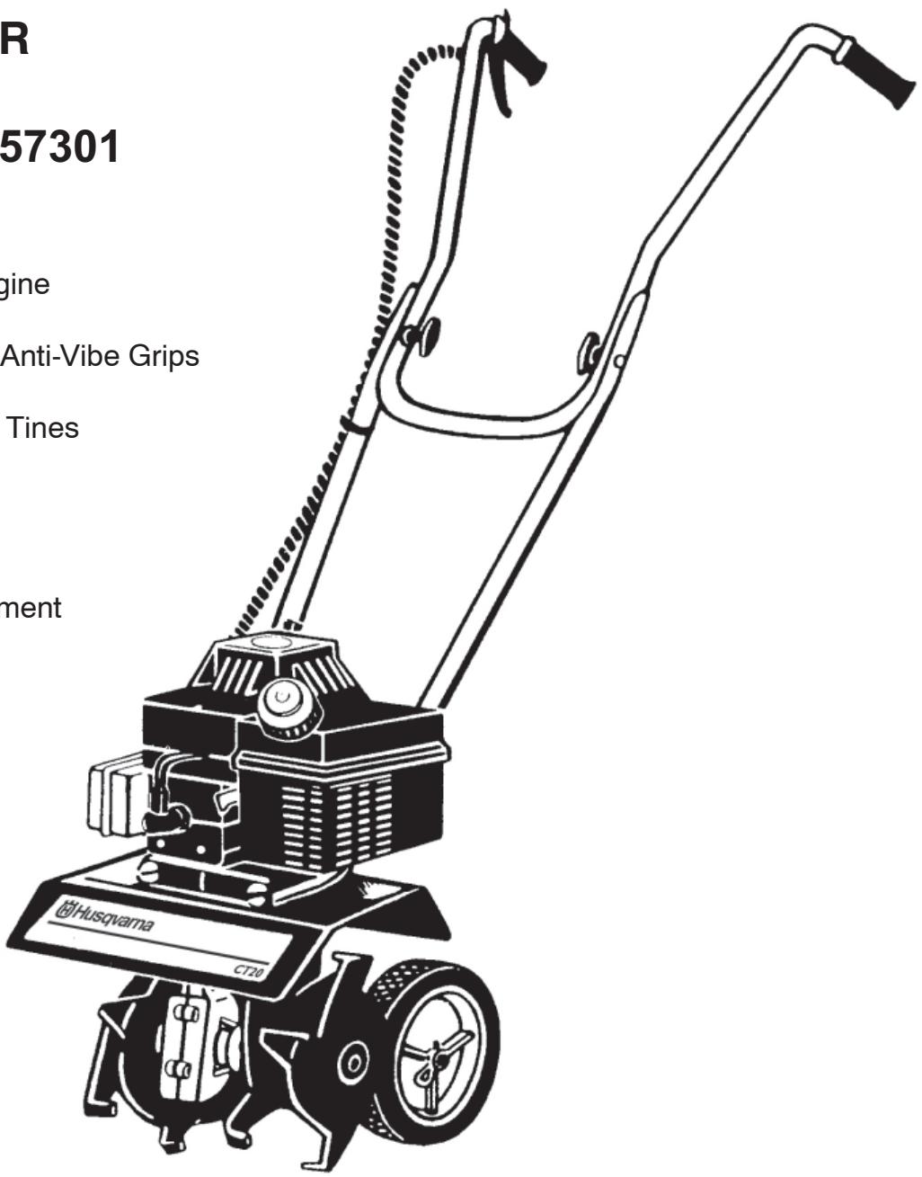
USER MANUAL CT 20 HUSQVARNA
- Durable Tecumseh TC III Engine
- Positive On/Off Switch
- Heavy-Duty Handlebars with Anti-Vibe Grips
- Depth Control Bar
- Four Heavy-Duty Removable Tines
- 6" or 10" Cultivating Width
Tine Speed—162 RPM - Worm Gear Drive
- Approx. Weight—25 Lbs.
- Transport Kit Standard Equipment
IMPORTANT!
"TO TILL & CULTIVATE IN ROCKY
SOIL CONDITIONS SEE PAGE 11
FOR ALTERNATE TINE ASSEMBLY"
IMPORTANTMESSAGE TO THE CONSUMER AND/OR OPERATOR

SAFETY SYMBOL
This symbol of safety will be found throughout this manual alerting you to the possibility of injury. Don't expose yourself or others to danger. Carefully read each message that follows the safety symbol.
SAFETY RULES AND PRECAUTIONS
As with any item of power equipment it is necessary that you learn and observe ALL safety precautions. This includes the care for the machine as well as personal safety. This machine is only as dangerous as the person who is operating it. DO NOT BE CARELESS! In the beginning you will be cautious. Don't allow yourself to become careless after you have gotten acquainted with the machine and its operation. DON'T EXPOSE YOURSELF OR OTHERS TO DANGER. After you have become acquainted with this machine and formed good operational habits, your proficiency will improve rapidly toward expert ability.

NEVER allow children to operate this unit.
NEVER allow adults to operate the equipment without proper instruction.
Keep area of operation clear of all persons, particularly small children and pets.

DON'T OVERLOOK THESE PRECAUTIONS, USE THEM!
IMPORTANT
SAFE OPERATION PRACTICES FOR WALK-BEHIND POWERED ROTARY TILLERS

PREPARATION
- Read the operating and service instruction manual carefully. Be thoroughly familiar with the controls and the proper use of the equipment. Know how to stop the unit and disengage the controls quickly.
- THOROUGHLY INSPECT the area to be tilled or cultivated and remove all foreign objects.
- DO NOT operate the machine without wearing adequate outer garments. Wear footwear which will improve footing on slippery surfaces and will resist penetration.
- HANDLE FUEL WITH CARE, IT IS HIGHLY FLAMMABLE.
a) Use an approved fuel container.
b) NEVER add fuel to a running engine or to a hot engine.
c) Fill fuel tank outdoors with extreme care. Never fill fuel tank indoors.
d) Replace gasoline cap securely and clean up spilled fuel before restarting.
- Before starting engine, be sure that the throttle lever is released so that the centrifugal clutch is not engaged.
- NEVER attempt to make any adjustments while the engine is running (except when recommended).

OPERATION
- NEVER transport this machine when the engine is running. SHUT THE ENGINE OFF before transporting the machine.
- DO NOT put hands or feet near or under rotating parts.
- SHUT OFF ENGINE before crossing gravel drives, walks, or roads. Stay alert for hidden hazards or traffic.
- After striking a foreign object, STOP THE ENGINE. Disconnect the spark plug wire, and keep the wire away from the plug to prevent accidental starting. Thoroughly inspect the machine for any damage and repair the damage before restarting and operating.
- EXERCISE CAUTION to avoid slipping or falling.
- If the machine should start to vibrate abnormally, STOP THE ENGINE, disconnect the spark plug wire, and check immediately for the cause. Vibration is generally a warning of trouble.
- STOP THE ENGINE whenever you leave the operating position. Also disconnect the spark plug wire before unclogging the tines and when making any repairs, adjustments, and inspections.
-
Take all possible precautions when leaving the machine unattended. STOP THE ENGINE.
-
Before cleaning, repairing, or inspecting, STOP THE ENGINE, make certain all moving parts have stopped, and disconnect the spark plug wire.
- NEVER run engine indoors. Exhaust fumes contain Carbon Monoxide which is an ODDLESS and DEADLY POISONOUS GAS.
- NEVER operate the Tiller/Cultivator without the proper guards, plates, or other safety protective devices in place.
- KEEP CHILDREN AND PETS AWAY.
- DO NOT overload the machine's capacity by attempting to till too deep at too fast a rate.
- NEVER operate the Tiller/Cultivator at high transport speeds on slippery surfaces. Look behind and use care when backing.
- NEVER allow bystanders near the Tiller/Cultivator.
- NEVER operate this machine without good visibility or light.
- DO NOT till or cultivate near underground electrical cables, telephone lines, pipes, or hoses. If in doubt about their location, contact your telephone or utility company to locate underground services.
- BE AWARE that the Tiller/Cultivator could unexpectedly bounce upward, or jump forward if the tines should strike extremely hard packed soil, frozen ground, or buried obstacles such as large stones, roots or stumps.
- DO NOT operate the Tiller/Cultivator on slopes that are too steep for safety.
- USE ONLY attachments and accessories that are approved by Hoffco, Inc.
- NEVER operate this machine when you are under the influence of alcohol, drugs, or medication.
- DO NOT touch engine parts which may be hot from operation. Allow parts to cool before inspecting, cleaning, or repairing this machine.
- The operation of any powered machine can result in foreign objects being thrown by high speed rotating parts. ALWAYS WEAR SAFETY GLASSES OR OTHER EYE PROTECTION WHEN OPERATING THIS MACHINE.

WARNING: TO PURCHASERS OF INTERNAL COMBUSTION ENGINE EQUIPPED MACHINERY OR DEVICES
This equipment does not include a spark arresting muffler.
Under California Law, you are not permitted to operate an internal combustion engine using hydrocarbon fuels on any forest covered, brush covered, or grass covered land, or land covered with grain, hay, or other flammable agricultural crop, without an engine spark arrestor in continuous effective working order. The engine on your Tiller/Cultivator, like most garden equipment, is an internal combustion engine that burns gasoline, a hydrocarbon fuel; therefore, it must be equipped with a spark arrestor muffler in proper working order. The spark arrestor must be attached to the engine exhaust system in such a manner that flames or heat from the system will not ignite flammable material. Failure of the operator to comply with this regulation is a misdemeanor under California Law.

WARNING: THE ENGINE EXHAUST FROM THIS PRODUCT CONTAINS CHEMICALS KNOWN TO THE STATE OF CALIFORNIA TO CAUSE CANCER, BIRTH DEFECTS OR OTHER REPRODUCTIVE HARM.
TABLE OF CONTENTS
DESCRIPTION
Safety Rules and Precautions 2-3
Assembly 5-6
Pre-Operation/Starting. 6-8
Operating Techniques and Handy Tips. 8
Adjustments/Maintenance 9-11
Tine Patterns for Stony or Rocky Soil 11
Carburetor Adjustments/Storage 12
Illustrated Parts Lists 13-21
Warranty. Back Cover
IMPORTANT!
THESE PRECAUTIONARY DECALS ARE STRATEGICALLY PLACED ON YOUR UNIT FOR YOU, THE USER...
PLEASE READ CAREFULLY!
WARNING!
ROTATING TINES
CAN CAUSE INJURY

KEEP
AWAY
FROM
ROTATING
TINES
CAUTION!
READ THE OPERATORS MANUAL
- KNOW THE LOCATION AND FUNCTION OF ALL CONTROLS
- KEEP ALL SHIELDS AND SAFETY DEVICES IN PLACE
- NEVER ALLOW CHILDREN OR UNINSTRUCTED ADULTS TO OPERATE THIS MACHINE
- SHUT OFF ENGINE TO UNCLOG TINES OR MAKE REPAIRS
DRESS PROPERLY - DO NOT WEAR LOOSE CLOTHING OR JEWELRY - ALWAYS WEAR GOGGLES FOR EYE PROTECTION
- KEEP CHILDREN, PETS AND BYSTANDERS AT A SAFE DISTANCE
IMPORTANT
THROTTLE CONTROL
OPERATION
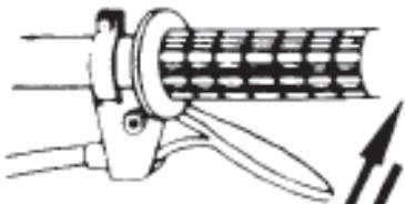
PULL—FAST
RELEASE-IDLE
ASSEMBLY
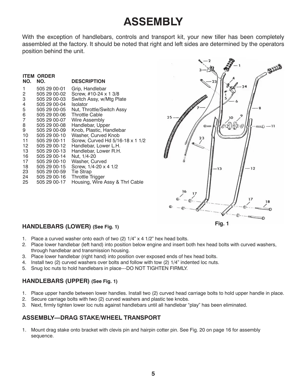
With the exception of handlebars, controls and transport kit, your new tiller has been completely assembled at the factory. It should be noted that right and left sides are determined by the operators position behind the unit.
ITEM ORDER
NO. NO.
DESCRIPTION
1 5052900-01
Grip, Handlebar
2 505 29 00-02
Screw, #10-24 x 1 3/8
3 5052900-03
Switch Assy, w/Mtg Plate
4 5052900-04
Isolator
5 5052900-05
Nut, Throttle/Switch Assy
6 5052900-06
Throttle Cable
7 5052900-07
Wire Assembly
8 5052900-08
Handlebar, Upper
9 5052900-09
Knob, Plastic, Handlebar
10 5052900-10
Washer, Curved Knob
11 5052900-11
Screw, Curved Hd 5/16-18 x 1 1/2
12 505 29 00-12
Handlebar, Lower L.H.
13 5052900-13
Handlebar, Lower R.H.
16 5052900-14
Nut, 1/4-20
17 5052900-10
Washer, Curved
18 5052900-15
Screw, 1 / 4 - 20 × 4 × 1 / 2
23 505 29 00-59
Tie Strap
24 505 29 00-16
Throttle Trigger
25 505 29 00-17
Housing, Wire Assy & Thrl Cable
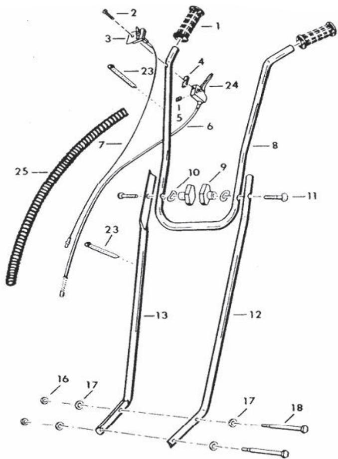
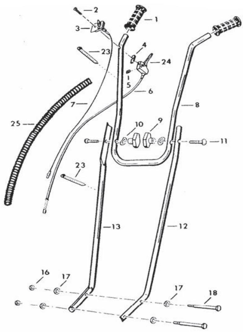
Fig. 1
HANDLEBARS (LOWER) (See Fig. 1)
- Place a curved washer onto each of two (2) 1/4 ” x 4 1/2 ” hex head bolts.
- Place lower handlebar (left hand) into position below engine and insert both hex head bolts with curved washers, through handlebar and transmission housing.
- Place lower handlebar (right hand) into position over exposed ends of hex head bolts.
- Install two (2) curved washers over bolts and follow with tow (2) 1/4 " indented loc nuts.
- Snug loc nuts to hold handlebars in place---DO NOT TIGHTEN FIRMLY.
HANDLEBARS (UPPER) (See Fig. 1)
- Place upper handle between lower handles. Install two (2) curved head carriage bolts to hold upper handle in place.
- Secure carriage bolts with two (2) curved washers and plastic tee knobs.
- Next, firmly tighten lower loc nuts against handlebars until all handlebar "play" has been eliminated.
ASSEMBLY—DRAG STAKE/WHEEL TRANSPORT
- Mount drag stake onto bracket with clevis pin and hairpin cotter pin. See Fig. 20 on page 16 for assembly sequence.
THROTTLE CABLE
Unwind throttle cable from around engine.
CAUTION: Be careful not to kink cable.
ON/OFF SWITCH
- Place 1 3/8" long slotted pan head screw into switch plate and down through hole in upper right hand handlebar. (See Fig. 2)
- Place rubber isolator over screw underneath handlebar. Follow with throttle trigger body.
- Place flat nut though slot in side of throttle trigger and tighten screw to secure throttle control to handlebar.

Fig. 2
- Push 2 terminals of kill wire (See Fig. 3) onto 2 prongs of shut off switch.
- Push other end of kill wire onto engine.

Fig. 3
- Retain kill wire and throttle cable to right handle bar using two (2) nylon tie straps. Cut off loose ends of the straps. (See Fig. 4)
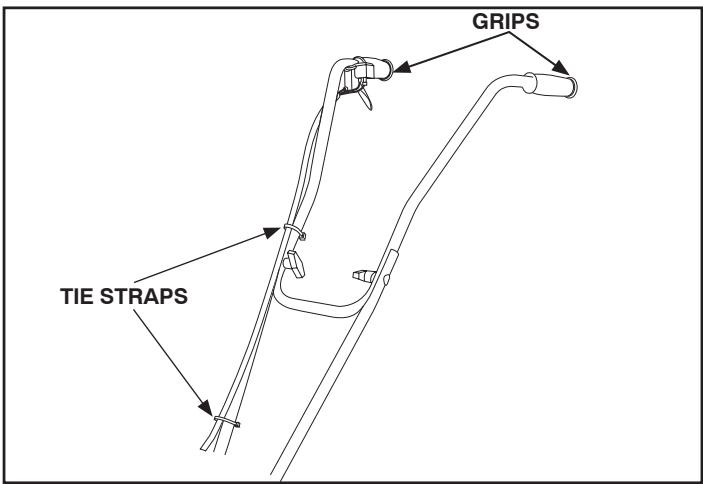
Fig. 4
- Install grips.
- Tine spacers provided can be placed in toolbox or garage shelf (see page 9).
- Fuel mix cup is provided for your convenience.
THIS COMPLETES THE ASSEMBLY OF YOUR UNIT. RE-CHECK ALL SCREWS AND NUTS TO BE SURE THEY ARE TIGHT.
As with any item of power equipment, it is necessary that you learn and observe ALL Safety precautions. This includes care of the machine as well as personal safety. DO NOT BE CARELESS!
Read the operating instruction manual carefully. Be thoroughly familiar with the controls and proper use of the equipment.
Always wear goggles or face shield for eye protection. It is advisable to wear protective head gear. These precautions are used to prevent the possibility of being struck by objects thrown from the rotating tines.
It is advisable to wear a long sleeve shirt or jacket. Don't wear shorts. Don't wear loose clothing or jewelry.
Do not operate this unit when barefoot or wearing open sandals. Always wear substantial footwear; leather work shoes or short boots function well for most people. Either will help protect the operator's ankles and shins from objects being thrown by rotating tines.
PRE-OPERATION

DANGER!
DO NOT SMOKE while filling the tank, or starting the engine. Be sure the proper fuel is used. Read the fuel instructions in the manual and/or on the engine. Always store the fuel to be used in this machine in a properly marked container that is approved for such use.
STARTING INSTRUCTIONS
Be sure you are using the proper fuel and have read and understand all the instructions on the preceding pages.
WARNING-24:1- Disregard instructions on oil containers. Do not mix directly in fuel tank. Do not use multi-viscosity oils. Usehighspeedaircooled2-cycleoil.
| U.S | Imperial | Metric | |||
| Gas | Oil | Gas | Oil | Gas | Oil |
| Gal. | Oz. | Gal. | Oz. | Gal. | Oz. |
| 1 | 5 | 1 | 6 | 4 | 166 |
| 2 | 10 | 2 | 12 | 8 | 322 |
To start engine, place the unit in a flat, clear area.
Move the On/Off Switch to the "I" position.
ON/OFF SWITCH
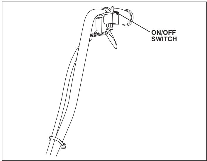
Fig. 5
WARNING: If you are unable to start this engine after following instructions in this manual, contact your Authorized Tecumseh Servicing Dealer. To avoid serious burn injuries or damage to your engine, DO NOT attempt to start or troubleshoot this engine in any other way. For example:
DO NOT use starting fluid.
- DO NOT spray flammable liquids into carburetor or onto air cleaner.
- DO NOT put flammable liquids into carburetor or onto air cleaner.
- DO NOT operate engine or pull on starter rope with spark plug removed. Fuel can spray from spark plug hole and ignite.
- To avoid carbon monoxide poisoning, make sure engine is outdoors in a well -ventilated area.
- Move rocker switch to "I" position.
- Move choke control lever to "Full Choke" Position (see equipment manufacturer's instructions). See Fig. 7
Note:
If restarting a warm engine after a short shutdown, move choke lever to "NO CHoke" position.
CAUTION: DO NOT start engine without pushing in yellow compression relief valve FIRST. Failure to do so may result in bruised fingers and accidental equipment movement which could result in minor or moderate injury.
- Push yellow compression relief valve in. See Fig. 8. Note:
Yellow compression relief valve will "pop" outward once engine starts.
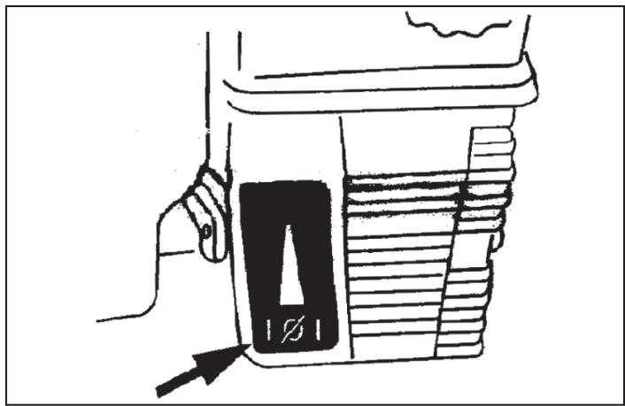
Fig. 6 Typical Engine Choke Symbol
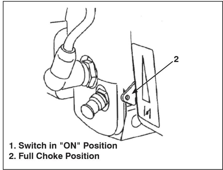
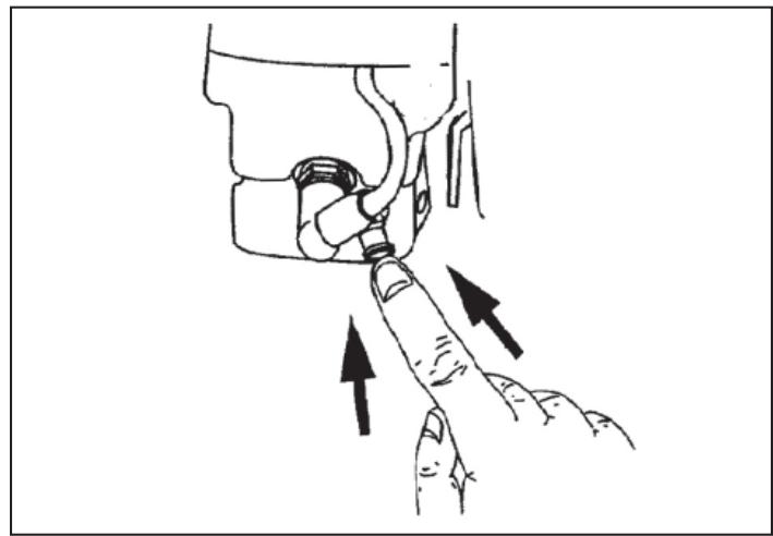
Fig. 7 Switch and Full Choke Positions
Fig. 8 Yellow Compression Relief Valve

WARNING: When pulling starter rope, the rope is unexpectedly jerk back toward engine causing serious injury. To avoid this risk, carefully follow these instructions:
Move rocker switch to "I" position.
- Grasp starter cord handle. Se Fig. 9
a. Pull rope out slowly until you feel drag.
b. Without allowing the rope to retract, continue pulling rope with one rapid full arm stroke.
c. Return rope slowly to original position.
Note:
Following the instructions listed in the steps above avoids potential damage to the recoil mechanism.
- If engine fails to start after 3 attempts repeat steps 2 thru 5 and try again.
- When engine starts:
a. Momentarily move choke lever to "1/2 CHoke" position until engine runs smoothly.
b. Next, move choke lever to "NO CHoke" position.
Note:
If engine starts but falters when choke in moved to "NO CHoke" position:
a. Momentarily move choke lever to "FULL CHoke" position.
b. Next, move choke lever to "NO CHoke" until engine runs smoothly.
c. Finally, move control to "NO CHOKE" position.
If engine dies after choke is moved to "NO CHoke" position, repeat steps 2 thru 7 to restart engine.
-
If engine fires but does not continue to run, move choke control lever to "NO CHoke" position.
-
Push yellow compression relief valve in.
Pull starter rope again. -
If engine fails to start after 3 attempts move choke control to "FULL CHoke" position.
-
Push yellow compression relief valve in.
Pull starter rope again. -
If engine does not start after following steps 1 thru 9, contact your Authorized Tecumseh Servicing Dealer. DO NOT attempt to start or troubleshoot this engine in any other way.
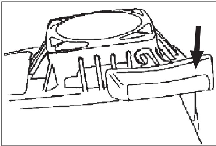
Fig. 9 Starter Cord Handle Location
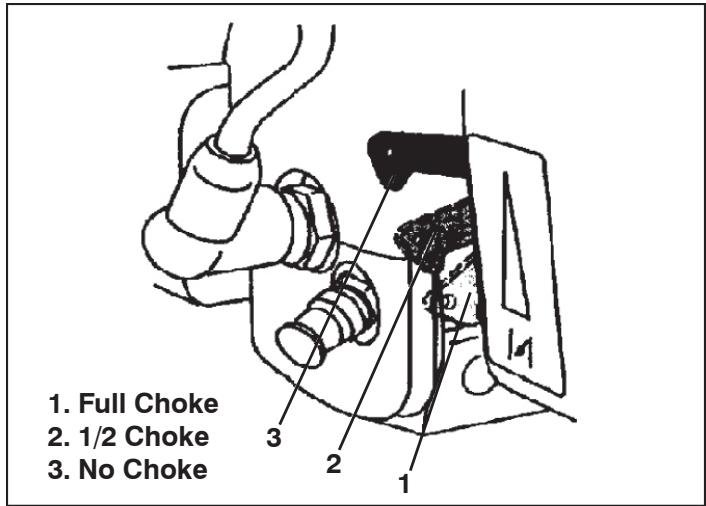
Fig. 10 Choke Lever Position
After the engine is started and has run for a few seconds, move the choke lever as far as it will go in the opposite direction from the starting position.
Tilt the unit back onto the drag stake to raise the tines off the ground.
With the tines still off the ground, squeeze and release the throttle trigger a few times. If the tines do not stop rotating when trigger is released, adjust carburetor idle speed as instructed in Adjustment/Maintenance section.
To shut off the engine, release the throttle control lever and move the On/Off Switch to the "O" position.
OPERATING TECHNIQUE AND HANDY TIPS
- Start engine and tilt unit back until tines are off the ground. Squeeze throttle lever to full speed position (lever tight against grip). Remember, this unit is equipped with a governed engine and must always be run at full speed position.
- Lower front of unit until tines begin to dig into ground to start filling.
- Unit will tend to walk forward at this point and must be firmly held back to allow tines to till.
- If adjustments to tilling depth must be made, proceed as follows:
a. Shut engine off by moving switch to "O" position.
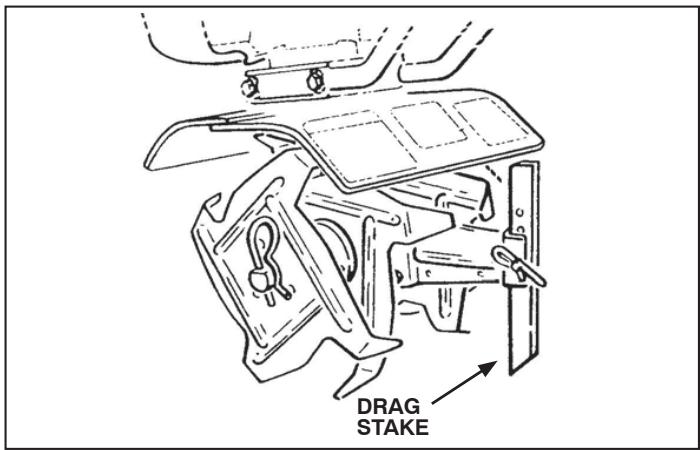
Fig. 11
b. Remove hairpin cotter and clevis pin from drag stake and adjust upward if unit is tilling too deeply. Adjust stake downward if more depth is necessary.
c. Move switch to "I" position and restart engine to continue tilling.
TINE SPACERS
The two tine spacers provided can be used to replace outside tines to narrow tilled path.

DANGER!
ALWAYS MOVE SWITCH TO "O" POSITION AND REMOVE SPARK PLUG WIRE BEFORE TRYING TO REMOVE OBSTRUCTIONS. CLEAN UNIT AFTER EACH OPERATION.*
*ALWAYS CLEAN UNIT AFTER EACH OPERATION. This includes removing any string, wire, vegetation or other obstructions that have wrapped around the tine shaft.
ADJUSTMENTS/MAINTENANCE
LUBRICATION OF TRANSMISSION (See Fig. 12)
(Transmission is pre-lubricated at the factory.)
Lubricate transmission after every 100 hours of use, if you see no grease at air vent hole. Replacement grease should be a high quality petroleum based grease usually available in disposable guns at most hardware or automotive parts stores.
To lubricate transmission, proceed as follows:
- Lay tiller on left side so that the tine shaft is vertical.
- Wearing heavy gloves, remove both right side tines.
- Remove dust cap.
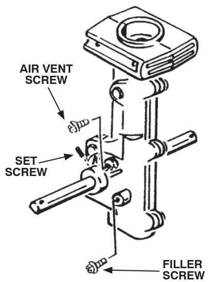
Fig. 12
Metal dust cap is held on with a set screw. Back set screw out approximately four turns. Dust cap should then slide off of the tine shaft.
- Remove air vent screw and fill hole screw from transmission.
- Fill transmission by using grease gun or grease applicator at the fill hole screw opening. Push gun or applicator against the opening so as to "seal" the nozzle of the gun or applicator against the casting embossment. Apply grease until you see the grease at the air vent hole.
- Re-install air vent screw and fill hole screw.
- Re-install dust cap.
- Place a few drops of oil on tine shaft before installing tines.
- Wearing heavy gloves, re-install tines. (For tine pattern, refer to Fig. 16 on page 11)
- Re-install hairpin.
AIR FILTER
NEVER RUN ENGINE WITHOUT COMPLETE AIR CLEANER INSTALLED ON ENGINE.
Clean and re-oil every 3 months or every 25 operating hours, whichever comes first. Clean daily if used in extremely dusty or dirty conditions.
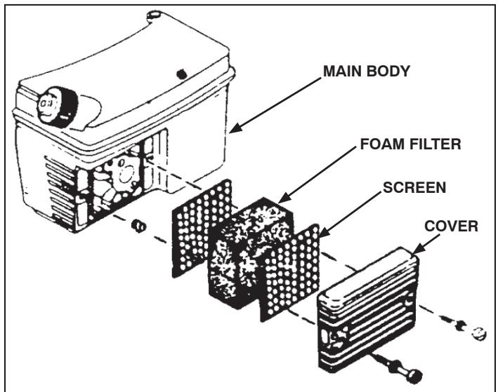
Fig. 13
KEEP YOUR AIR FILTER CLEAN! In a new machine, your filter should be clean. However, after you have used this machine for a while, your filter will accumulate dirt and dust. Check the condition of your filter frequently. A dirty or clogged filter element will restrict the air flow to the carburetor, thus changing the air-fuel mix. This will create symptoms often mistaken for the carburetor being out of proper adjustment. To clean the filter, follow these steps:
- Loosen and remove two screws from cover.
- Remove COVER, SCREEN, and FOAM FILTER from MAIN BODY.
- Inspect SCREEN(S) and FOAM FILTER for discoloration or dirt accumulation. Clean if either is present.
TO CLEAN SCREEN
a) Wash SCREEN in water and detergent solution.
b) Rinse thoroughly in clean water, then air dry.
TO CLEAN AND RE-OIL FOAM FILTER
a) Wash FOAM FILTER in water and detergent solution and squeeze (don't twist) until all dirt is removed.
b) Rinse thoroughly in clear water.
c) Wrap in a clean cloth and squeeze (don't twist) until completely dry.
d) Saturate FOAM FILTER with clean engine oil, squeeze (don't twist) to distribute oil and remove excess oil.
- Clean inside of COVER and BODY thoroughly.
- Reassemble AIR CLEANER as shown in Fig. 13.

SPARK PLUG
Fig. 14
- Clean area around SPARK PLUG base.
- Remove and inspect SPARK PLUG.
- Replace SPARK PLUG if ELECTRODES are pitted or burned or if PORCELAIN is cracked. Replace as follows:
For TC300 use Champion RCJ8Y or equivalent.
NOTE: In Canada, replace spark plug with a resistor plug.
- If reusing SPARK PLUG, clean it by carefully scraping ELECTRODES (don't wire brush or sand blast). Be sure entire SPARK PLUG is clean.
- Check ELECTRODES GAP with wire feeler gauge and set gap at .030 if necessary.
- Install SPARK PLUG in engine and tighten to 15 foot poundstorque.lflackingtorquewrench,tightensecurely.
TINE REPLACEMENT
Remember that right and left sides of your unit are determined from the operator's position behind the unit. Note that all four tines of this unit are different and must be installed correctly or tiller will not function properly. Tines will wear and become quite sharp. Be very careful when replacing tines. If tines are being replaced due to wear, all four tines should be replaced as a set. (See Fig. 15)

ALWAYS MOVE SWITCH TO “O” POSITION
AND REMOVE SPARK PLUG WIRE BEFORE REPLACING TINES.
- Remove hairpin cotter from tine shafts.
- Wearing heavy gloves, remove tines.
- Clean tine shaft. Apply a few drops of oil.
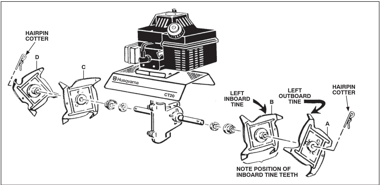
Fig. 15
-
For regular tine pattern, install inboard tines, being careful to install tine with stamped letter "C" on right side of tiller and tine stamped letter "B" on left side of tiller. (NOTE: Inboard tines have tines formed in opposite direction.)
-
Install outboard tines, again being careful to install tine with stamped letter "D" on right side and tine with stamped letter "A" on left side. (NOTE: Outboard tines have tines formed in one direction.)
- Install hairpin coters through holes in shaft.
TINE PATTERNS FOR STONY OR ROCKY SOIL (See Fig. 16)
If you are tilling in stony or rocky soil, and experience continual rock jams, there are two additional tine patterns that will help alleviate the problem.
- Shut off engine.
- Disconnect spark plug wire.
Wearing heavy gloves, remove tines and re-install in one of the two stony soil patterns shown in Fig. 16. If you experience difficulty in removing tines, as a result of dirt or other foreign matter on shaft, you may wish to apply a penetrating oil on the shaft. When re-installing the tines make sure tine shaft and tine hubs are clean and free of foreign material. The tines should easily slide onto the shaft.
"DO NOT FORCE THE TINES ONTO THE SHAFT."
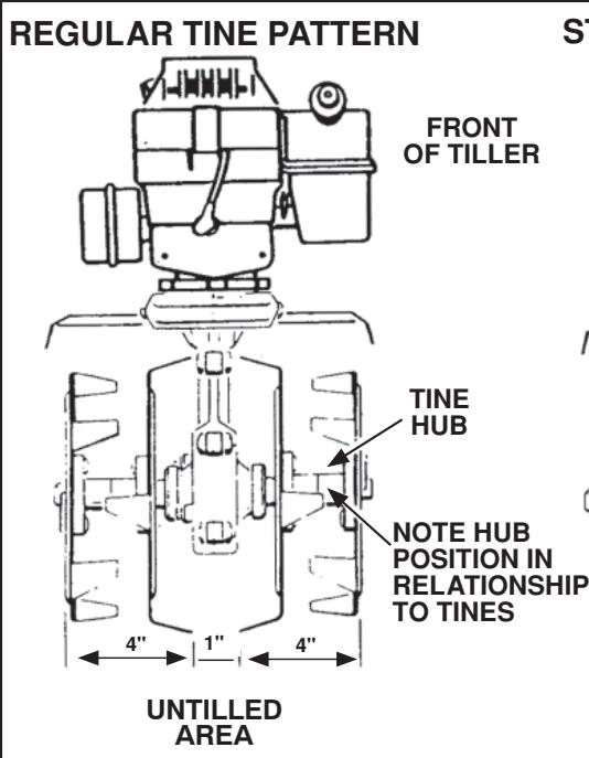
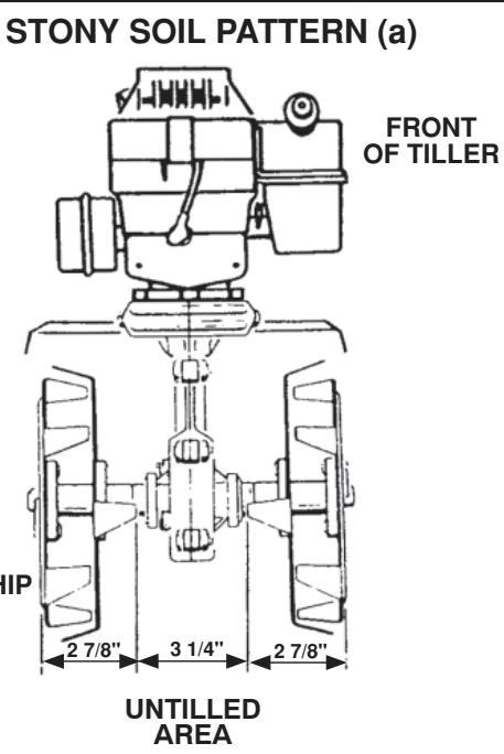
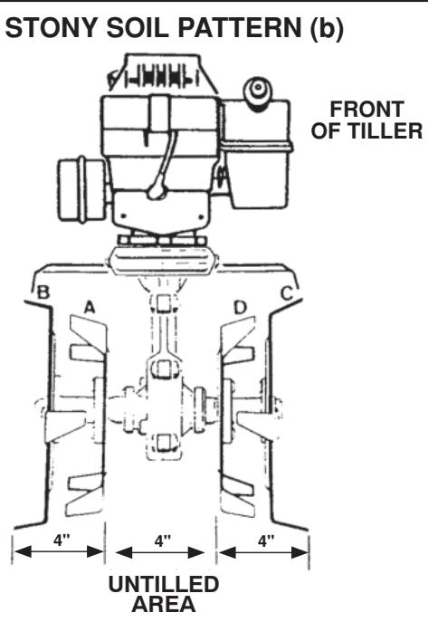
Fig. 16
NOTE: In the stony soil tine patterns the center gap is wider than in regular tine pattern, see Fig. 16. This will require additional passes to till this untilled area.
When the tines are properly mounted, the angled portions of the tine blade should enter the soil first, not the straight portions, see Fig. 17.
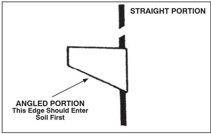
Fig. 17
NARROW CULTIVATING
The two outer tines can be removed to give you a narrower cultivating width. This width is approximately 6". This will give you the ability to get between very closely spaced plants. In order to do this, pull the hairpin out of the hole in the outboard end of the tine shaft. Slide the tines off the tine shaft and place a tine spacer, included with your tiller, over the tine shaft. Secure the spacer with the hairpin cotter in the outer hole.
THROTTLE CABLE INSPECTION (See Fig. 18)
Verify that the throttle trigger operates smoothly, releases properly and the throttle cable is undamaged. If there is visible damage, or if the throttle lever does not operate smoothly or release properly, take your tiller to an authorized service center.
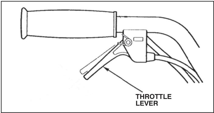
Fig. 18
CARBURETOR ADJUSTMENT (See Fig. 19)
With the engine shut off... locate the idle adjustment screw as shown in the illustration.
NOTE: Illustration is a bottom view of the engine.
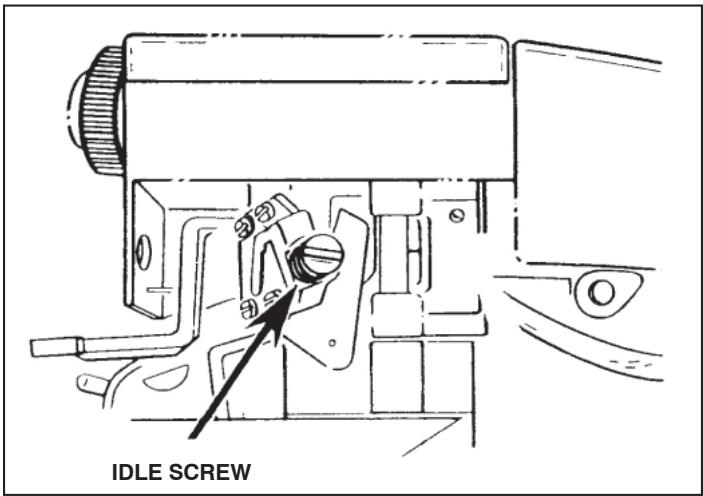
Fig. 19
- START THE ENGINE AND LET IT WARM UP. Do not adjust carburetor when engine is cold.
If tines continue to rotate after throttle lever is released, proceed as follows:
- Turn the idle speed adjustment screw to the left (counter-clockwise) until the tines stop rotating.

DANGER!

NEVER TAMPER WITH ENGINE GOVERNORIS FACTORY SET FOR PROPER ENGINE. OVER-SPEEDING ENGINE MAY INCREASEANGER OF PERSONAL INJURY AND WILL
VOID ENGINE WARRANTY. If you think the engine governed high speed needs adjusting, contact your nearby authorized Tecumseh Service Dealer, who has the proper equipment and experience to make necessary adjustments.

DANGER!

NEVER STORE UNIT WITH GASOLINE IN BANK IN A BUILDING WHERE FUMES MAY I AN OPEN FLAME OR SPARK.

BE SURE ENGINE HAS COOLED BEFOREING IN ANY ENCLOSURE.
WHEN STORING FOR A LONG PERIOD OF TIME... Drain the fuel from the tank and run the engine until it stops. By clearing the carburetor you eliminate the possibility of varnish deposits that build up in the carburetor when the fuel mixture is allowed to remain in the carburetor and tank for a longer period of time. Also, remove the spark plug and insert approximately on teaspoon of oil (this may be the same oil as used in the fuel mix) directly into the cylinder. Pull the recoil rope/starter several times to distribute the oil over the cylinder walls, then replace the spark plug. Cover the powerhead by wrapping it with a plastic bag, etc., and store in a dry place. Some owners prefer to hang the unit on the wall to reduce the possibility of damage.
CLEARING THE TANK AND CARBURETOR OF FUEL WHEN STORING WILL MAKE A SUBSTANTIAL DIFFERENCE IN STARTING THE ENGINE THE NEXT TIME THE MACHINE IS USED!
HANDLEBARS/GRIP/ON-OFF SWITCH/THROTTLE CONTROL/THROTTLE CABLE
ITEM ORDER NO. NO.
| 1 | 505 29 00-01 | Grip, Handlebar | 2 |
| 2 | 505 29 00-02 | Screw, #10-24 x 1 3/8 | 1 |
| 3 | 505 29 00-03 | Switch Assy, w/Mtg Plate | 1 |
| 4 | 505 29 00-04 | Isolator | 1 |
| 5 | 505 29 00-05 | Nut, Throttle/Switch Assy | 1 |
| 6 | 505 29 00-06 | Throttle Cable | 1 |
| 7 | 505 29 00-07 | Wire Assembly | 1 |
| 8 | 505 29 00-08 | Handlebar, Upper | 1 |
| 9 | 505 29 00-09 | Knob, Plastic, Handlebar | 2 |
| 10 | 505 29 00-10 | Washer, Curved Knob | 2 |
| 11 | 505 29 00-11 | Screw, Curved Hd 5/16-18 x 1 1/2 | 2 |
| 12 | 505 29 00-12 | Handlebar, Lower L.H. | 1 |
| 13 | 505 29 00-13 | Handlebar, Lower R.H. | 1 |
| 16 | 505 29 00-14 | Nut, 1/4-20 | 2 |
| 17 | 505 29 00-10 | Washer, Curved | 4 |
| 18 | 505 29 00-15 | Screw, 1/4-20 x 4 1/2 | 2 |
| 23 | 505 29 00-59 | Tie Strap | 2 |
| 24 | 505 29 00-16 | Throttle Trigger | 1 |
| 25 | 505 29 00-17 | Housing, Wire Assy & Thr1 Cable | 1 |
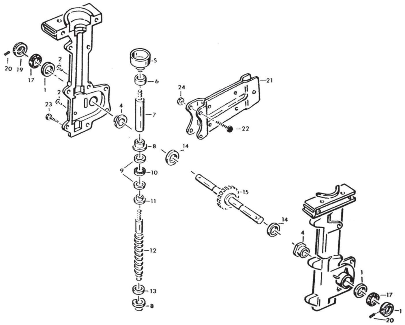
TRANSMISSION ASSEMBLY
ITEM ORDER
NO. NO.
1 5052900-18
2 505 29 00-19
4 5052900-20
5 5052900-21
6 5052900-22
7 5052900-23
8 5052900-24
9 5052900-25
10 5052900-26
11 5052900-27
12 505 29 00-28
13 5052900-29
14 5052900-30
15 5052900-31
17 5052900-32
19 5052900-33
20 505 29 00-34
21 505 29 00-35
22 505 29 00-36
23 505 29 00-37
24 505 29 00-38
-- 5052900-41
DESCRIPTION
Seal 2
Screw, Phillips Pan Hd 1/4-20 x 1/2 2
Bushing, Bronze 2
1
Bearing, Roller 1
Shaft, Connecting 1
Bushing, Bronze 2
Washer, Thrust 2
Bearing, Needle, Thrust 1
Washer, Adaptor 1
Shaft, Worm 1
Washer, Thrust 1
Washer, Thrust 2
Shaft, Tine, w/Worm Wheel 1
Felt Seal 2
Dirt Cap, Silver, Metal 2
SetScrew,#10-32x1/4 2
Bracket Assy, Drag Stake 1
Screw, 1 / 4 - 20× 1 2
Screw, 1 / 4 - 20× 7 / 8
Nut, 1/4-20 2
Transmission Assembly, Complete 1
QTY. REQ.
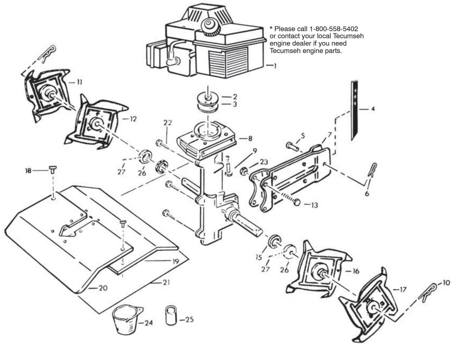
ENGINE/TRANSMISSION/TINES/SHIELD
ITEM ORDER
NO. NO.
DESCRIPTION
QTY. REQ.
1
Engine* 1
2 505 29 00-61
Clutch Assy 1
3 5052900-62
Spring, Clutch 2
4 5052900-39
Drag Stake 1
5 5052900-58
Pin, Clevis 5/16 x 7/8
6 5052900-40
Hairpin 1
7 5052900-35
Bracket Assembly 1
8 5052900-41
Transmission Assembly, Complete 1
9 5052900-42
Screw, Whizz Loc, 1/4-20 x 2 4
10 5052900-43
Hairpin 2
11 5052900-44
Tine & Hub, R.H. Outbrd (D) 1
12 505 29 00-45
Tine & Hub, R.H. Inbrd ( C) 1
13 5052900-36
Screw, 1 / 4 - 20× 1" 2
15 5052900-32
Felt Seal 2
16 5052900-46
Tine & Hub, L.H. Inbrd (B) 1
17 5052900-47
Tine & Hub, L.H. Outbrd (A) 1
22 505 29 00-37
Screw, 1/4 - 20 x 7/8, Thrd. From
23 505 29 00-14
Nut, 1/4 - 20 2
24 505 29 00-63
Fuel Mix Cup
25 505 29 00-48
Tine Spacers 2
26 505 29 00-33
Dirt Cap, Silver Metal 2
27 505 29 00-34
Set Screw, #10 - 32 x 1/4, Metal Dirt Cap 2
TRANSPORT KIT ASSEMBLY
- Assemble the wheel assembly and install the wheel assembly on the tiller with the arrow up as shown. Torque: 14 ft-lb (20 N-m).
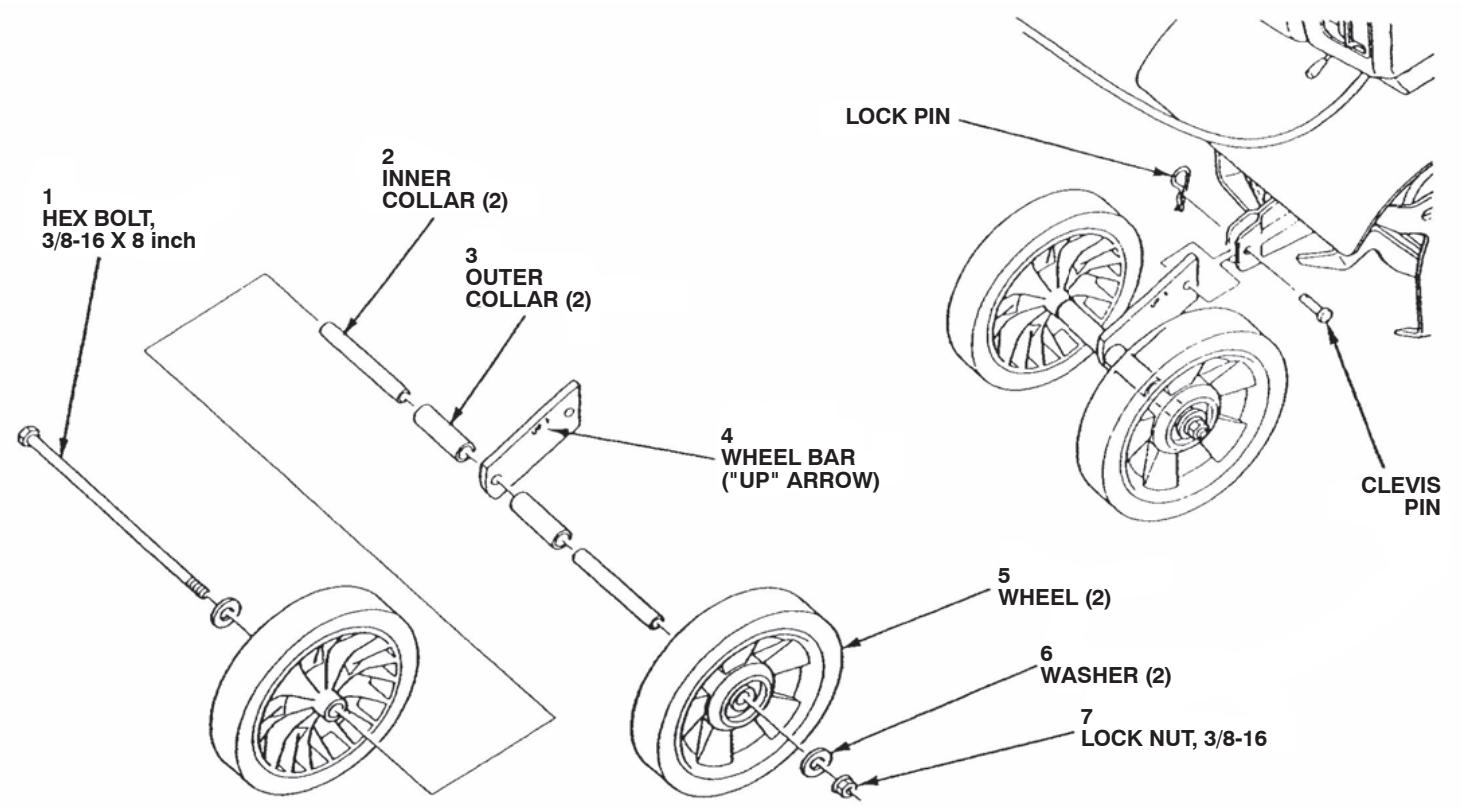
Fig. 20
NOTE: PLEASE FOLLOW THE DIRECTIONS SHOWN ABOVE TO ASSEMBLE YOUR WHEEL KIT.
ITEM ORDER NO.
NO.
1 5052900-49
2 505 29 00-50
3 5052900-51
4 5052900-52
5 5052900-53
6 5052900-54
7 5052900-55
-- 5052900-56
DESCRIPTION
Hex Bolt 3/8-16 x 8
Inner Collar
Outer Collar
Wheel Bar
Wheel
Washer
Lock-Nut, 3/8-16
CT20 Decal
QTY. REQ.
1
2
2
1
2
2
1
1
NOTES
NOTES
NOTES

Husqvarna WARRANTY STATEMENT
SECTION 1: LIMITED WARRANTY
Husqvarma Forest & Garden Company ("Husqvarma") warrants Husqvarna product to the original purchaser to be free from defects in material and workmanship from the date of purchase for the "Warranty Period" of the product as set forth below: Lifetime Warranty (Parts and Labor): All tiller tines and trimmer shafts against breakage. Proof of purchase required. Lifetime Warranty ("PARTS ONLY" after initial warranty expiration): Ignition coils and modules on handheld product. Proof of purchase required.
WARRANTY SCHEDULE FOR TURF CARE Equipment - Zero Turn Riders
(New warranty applies to units sold after August 1, 2005. Also applies to units factory-equipped with R.O.P.S. EZ Zero Turn Riders: 3 year consumer warranty or 600 hours of use (when used solely at the owner's residence.)
EZ & MZ Zero Turn Riders: 1 year commercial warranty or 600 hours of use.
iZ, LZ & BZ Zero Turn Riders: 5 year consumer warranty or 1,500 hours of use.
iZ, LZ & BZ Zero Turn Riders: 5 year commercial warranty or 1,500 hours of use.
3 Year or 1,500 Hour Commercial Use Warranty: spindles on zero turn riders, hydraulic pumps and wheel motors. Warranty Schedule for Turf Care Walk Behind Units - W, WG & WH Zero Turn Riders - 3 year consumer and commercial warranty. New warranty applies to units sold after August 1, 2005. Also applies to units factory-equipped with R.O.P.S.
2 Year COMMERCIAL and CONSUMER Warranty: all Husqvarna ground-engaging commercial equipment. WARRANTY SCHEDULE FOR CONSUMER TURF CARE EQUIPMENT:
2 Year Consumer Warranty: Automatic mower, all Residential Zero Turn Riders, all lawn, yard and garden tractors, all noncommercial walk behind mowers, tillers, snow blowers, electrical products and power-assist collection systems for noncommercial, nonprofessional, noninstitutional or nonincome producing use, except as herein stated. All consumer product use must have been limited to the owner's residence.
WARRANTY SCHEDULE FOR CONSUMER FOREST & GARDEN EQUIPMENT:
2 Year Consumer Warranty: all consumer chain saws, trimmers, brushcutters, clearing saws, handheld blowers, backpack blowers, hedge trimmers, and electrical products for noncommercial, nonprofessional, noninstitutional or nonincome producing use, except as herein stated. All consumer product use must have been limited to the owner's residence.
2 Year or 2,000 Hour Powertrain & 1 Year or 1,000 Hour Body Warranty: Husqvarna Utility Vehicles.
1 Year Warranty: Power cutters, stump grinder, pole pruners and pole saws for non-commercial, non-professional, noninstitutional, non-municipality or non-income producing use. All 300 series trimmers, brushcutters, clearing saws, hovering trimmers, stick edgers, backpack blowers, hand held blowers, hedge trimmers, power-assist collection systems for commercial, institutional, professional or income producing purposes or use.
1 Year Conditional Component Warranty: Chain saw crankshafts for commercial/professional use (parts and labor). Saw must be operated with Husqvarna XP 2 cycle oil.
90 Day Commercial Warranty: Automatic mower, chain saws, 100 series trimmers, power cutters, stump grinders, pole saws, pole pruners, snow throwers, model series 580 & 600 walk-behind mowers, or any Husqvarna product used for commercial, institutional, professional, municipality or income producing purposes or use except as otherwise provided herein.
Batteries: 1 year prorated limited warranty with 100% replacement during the first 6 months.
Rental Warranty: 90 days on all applicable professional equipment reference warranty time period charts located in the back of the Retailer Warranty Policy & Procedure Manual.
Husqvarna Safety Apparel carries a 90-day warranty from the date of the customer's original purchase for defects in material and workmanship. Normal wear, tear or abuse is not covered under warranty. Product must be returned to Charlotte with a warranty claim form. All care and maintenance instructions must be followed as stated by the manufacturer on the care label. The fit of the protective apparel/boot is not covered under warranty.
30 Day Warranty: Replacement parts, accessories including bars and chains, tools and display items. Emission control system components necessary to comply with CARB-TIER II and EPA regulations, except for those components which are part of engine systems manufactured by third part engine manufacturers for which the purchaser has received a separate warranty with product at time of purchase.
SECTION 2: HUSQVARNA'S OBLIGATIONS UNDER THE WARRANTY
Husqvarna will repair or replace defective components without charge for parts or labor if a component fails because of a defect in material or workmanship during the warranty period.
SECTION 3: ITEMS NOT COVERED BY THIS WARRANTY
The following items are not covered by this warranty:
(1) Normal customer maintenance items which become worn through normal regular use, including, but not limited to, belts, blades, blade adapters, bulbs, clutches, clutch drums, filters, guide bars, lubricants, rewind springs, saw chain, spark plugs,
starter ropes and tiller tines;
(2) Natural discoloration of material due to ultraviolet light;
(3) Engine and drive systems not manufactured by Husqyarna; these items are covered by the respective manufacturer's warranty as provided in writing with the product information supplied at the time of purchase; all claims must be sent to the appropriate manufacturer;
(4) Lawn and garden attachments are covered by a third party which gives a warranty, all claims for warranty should be sent to the manufacturer.
(5) Commercial or consumer mowing decks with sand abrasion damage.
(6) Emission Control System components necessary to comply with CARB-TIER II and EPA regulations which are manufactured by third party engine manufacturer.
SECTION 4: EXCEPTIONS AND LIMITATIONS
This warranty shall be inapplicable to defects resulting from the following:
(1) Accident, abuse, misuse, negligence and neglect, including stale fuel, dirt, abrasives, moisture, rust, corrosion, or any adverse reaction due to incorrect storage or use habits;
(2) Failure to operate or maintain the unit in accordance with the Owner's/Operator's manual or instruction sheet furnished by Husqvarna;
(3) Alterations or modifications that change the intended use of the product or affects the product's performance, operation, safety, or durability, or causes the product to fail to comply with any applicable laws; or:
(4) Additional damage to parts or components due to continued use occurring after any of the above.
REPAIR OR REPLACEMENT AS PROVIDED UNDER THIS WARRANTY IS THE EXCLUSIVE REMEDY OF THE PURCHASER. HUSQVARNA SHALL NOT BE LIABLE FOR ANY INCIDENTAL OR CONSEQUENTIAL DAMAGES FOR BREACH OF ANY EXPRESS OR IMPLIED WARRANTY ON THESE PRODUCTS EXCEPT TO THE EXTENT PROHIBITED BY APPLICABLE LAW. ANY IMPLIED WARRANTY OF MERCHANTABILITY OR FITNESS FOR A PARTICULAR PURPOSE ON THESE PRODUCTS IS LIMITED IN DURATION TO THE WARRANTY PERIOD AS DEFINED IN THE LIMITED WARRANTY STATEMENT. HUSQVARNA RESERVES THE RIGHT TO CHANGE OR IMPROVE THE DESIGN OF THE PRODUCT WITHOUT NOTICE, AND DOES NOT ASSUME OBLIGATION TO UPDATE PREVIOUSLY MANUFACTURED PRODUCTS.
Some states do not allow the exclusion of incidental or consequential damages, or limitations on how long an implied warranty lasts, so the above limitations or exclusions may not apply to you. This warranty gives you specific legal rights, and you may also have other rights which vary from state to state.
SECTION 5: CUSTOMER RESPONSIBILITIES
The product must exhibit reasonable care, maintenance, operation, storage and general upkeep as written in the maintenance section of the Owner's/Operator's manual. Should an operational problem or failure occur, the product should not be used, but delivered as is to an authorized Husqvarna retailer for evaluation. Proof of purchase, as explained in section 6, rests solely with the customer.
SECTION 6: PROCEDURE TO OBTAIN WARRANTY CONSIDERATION
It is the Owner's and Retailer's responsibility to make certain that the Warranty Registration Card is properly filled out and mailed to Husqvarna Forest & Garden Company. This card should be mailed within ten (10) days from the date of purchase in order to confirm the warranty and to facilitate post-sale service.
Proof of purchase must be presented to the authorized Husqvarna retailer in order to obtain warranty service. This proof must include date purchased, model number, serial number, and complete name and address of the selling retailer.
To obtain the benefit of this warranty, the product believed to be defective must be delivered to an authorized Husqvarma retailer in a timely manner, no later than thirty (30) days from date of the operational problem or failure. The product must be delivered at the owner's expense. Downtime, pick-up and delivery charges are not covered by this warranty. An authorized Husqvarma retailer can be normally located through the "Yellow Pages" of the local telephone directory or by calling 1-800-HUSKY62 for a retailer in your area.
HUSQVARNA
7349 Statesville Road
Charlotte, NC 28269
2008

- IMPORTANT!
- IMPORTANTMESSAGE TO THE CONSUMER AND/OR OPERATOR
- SAFETY SYMBOL
- SAFETY RULES AND PRECAUTIONS
- IMPORTANT
- SAFE OPERATION PRACTICES FOR WALK-BEHIND POWERED ROTARY TILLERS
- PREPARATION
- OPERATION
- WARNING: TO PURCHASERS OF INTERNAL COMBUSTION ENGINE EQUIPPED MACHINERY OR DEVICES
- TABLE OF CONTENTS
- DESCRIPTION
- PLEASE READ CAREFULLY!
- WARNING!
- ROTATING TINES
- CAUTION!
- THROTTLE CONTROL
- ASSEMBLY
- ITEM ORDER
- NO.
- HANDLEBARS (LOWER) (See Fig. 1)
- HANDLEBARS (UPPER) (See Fig. 1)
- ASSEMBLY—DRAG STAKE/WHEEL TRANSPORT
- THROTTLE CABLE
- ON/OFF SWITCH
- THIS COMPLETES THE ASSEMBLY OF YOUR UNIT. RE-CHECK ALL SCREWS AND NUTS TO BE SURE THEY ARE TIGHT.
- PRE-OPERATION
- DANGER!
- STARTING INSTRUCTIONS
- Note:
- OPERATING TECHNIQUE AND HANDY TIPS
- TINE SPACERS
- ADJUSTMENTS/MAINTENANCE
- LUBRICATION OF TRANSMISSION (See Fig. 12)
- AIR FILTER
- NEVER RUN ENGINE WITHOUT COMPLETE AIR CLEANER INSTALLED ON ENGINE.
- TO CLEAN SCREEN
- TO CLEAN AND RE-OIL FOAM FILTER
- TINE REPLACEMENT
- ALWAYS MOVE SWITCH TO “O” POSITION
- AND REMOVE SPARK PLUG WIRE BEFORE REPLACING TINES.
- TINE PATTERNS FOR STONY OR ROCKY SOIL (See Fig. 16)
- NARROW CULTIVATING
- THROTTLE CABLE INSPECTION (See Fig. 18)
- CARBURETOR ADJUSTMENT (See Fig. 19)
- NEVER TAMPER WITH ENGINE GOVERNORIS FACTORY SET FOR PROPER ENGINE. OVER-SPEEDING ENGINE MAY INCREASEANGER OF PERSONAL INJURY AND WILL
- NEVER STORE UNIT WITH GASOLINE IN BANK IN A BUILDING WHERE FUMES MAY I AN OPEN FLAME OR SPARK.
- BE SURE ENGINE HAS COOLED BEFOREING IN ANY ENCLOSURE.
- HANDLEBARS/GRIP/ON-OFF SWITCH/THROTTLE CONTROL/THROTTLE CABLE
- TRANSMISSION ASSEMBLY
- REQ.
- ENGINE/TRANSMISSION/TINES/SHIELD
- TRANSPORT KIT ASSEMBLY
- ITEM ORDER NO.
- NO.
- NOTES
- Husqvarna WARRANTY STATEMENT
- SECTION 1: LIMITED WARRANTY
- WARRANTY SCHEDULE FOR TURF CARE Equipment - Zero Turn Riders
- WARRANTY SCHEDULE FOR CONSUMER FOREST & GARDEN EQUIPMENT:
- SECTION 2: HUSQVARNA'S OBLIGATIONS UNDER THE WARRANTY
- SECTION 3: ITEMS NOT COVERED BY THIS WARRANTY
- SECTION 4: EXCEPTIONS AND LIMITATIONS
- SECTION 5: CUSTOMER RESPONSIBILITIES
- SECTION 6: PROCEDURE TO OBTAIN WARRANTY CONSIDERATION
Brand : HUSQVARNA
Model : CT 20
Category : Tiller