
6801DB - Uncategorized MAKITA - Free user manual and instructions
Find the device manual for free 6801DB MAKITA in PDF.

| Product Type | Impact Drill |
| Brand | Makita |
| Model | 6801DB |
| Power Supply | Corded, 120V AC |
| Power Consumption | 500 W |
| No-Load Speed | 0 - 2800 rpm |
| Maximum Drilling Capacity (Steel) | 13 mm (1/2 in) |
| Maximum Drilling Capacity (Wood) | 25 mm (1 in) |
| Maximum Drilling Capacity (Concrete) | 13 mm (1/2 in) |
| Chuck Type | Keyless |
| Chuck Size | 1/2 in - 20 UNF |
| Impact Rate | 0 - 33600 bpm |
| Reversible | Yes |
| Variable Speed Trigger | Yes |
| Lock-On Button | Yes |
| Side Handle | Included |
| Depth Gauge | Included |
| Weight | 2.0 kg (4.4 lbs) |
| Dimensions (L x W x H) | 280 x 80 x 80 mm |
| Cord Length | 2.5 m (8.2 ft) |
| Sound Level | 85 dB(A) |
| Vibration Level | 15 m/s² |
| Maintenance | Keep ventilation slots clean; lubricate gears annually |
| Safety | Wear ear and eye protection; use auxiliary handle |
| Repairability | Authorized Makita service centers; spare parts available |
Frequently Asked Questions - 6801DB MAKITA
User questions about 6801DB MAKITA
0 question about this device. Answer the ones you know or ask your own.
Ask a new question about this device
Download the instructions for your Uncategorized in PDF format for free! Find your manual 6801DB - MAKITA and take your electronic device back in hand. On this page are published all the documents necessary for the use of your device. 6801DB by MAKITA.
USER MANUAL 6801DB MAKITA
natural_image
Line drawing of a handheld electric drill (no text or symbols)
1
2
3
4
5
6
7
8
Symbols
The followings show the symbols used for the tool. Be sure that you understand their meaning before use.
Symbole
□ Only for EU countries
Do not dispose of electric equipment together with household waste material!
In observance of European Directive 2002/96/EC on waste electrical and electronic equipment and its implementation in accordance with national law, electric equipment that have reached the end of their life must be collected separately and returned to an environmentally compatible recycling facility.
□ Nur für EU-Länder
Explanation of general view
| 1 Locking sleeve | 5 Locking position | 9 High |
| 2 Locator | 6 Gear housing | 10 Low |
| 3 B i t | 7 Switch trigger | 11 Speed control screw |
| 4 Magnetic bit holder | 8 Lock button | 12 Reversing switch lever |
SPECIFICATIONS
Model 6800DB 6800DBV 6801DB 6801DBV
Capacities
Drywall screw....No.6 No.6 No.6 No.6
Self drilling screw ....5 mm 5 mm 5mm 5mm
Bit shank size....1/4" Hex 1/4" Hex 1/4" Hex 1/4" Hex
| No load speed (RPM)......2,500 | 0–2,500 | 4,000 | 0–4,000 |
| Overall length......280 mm | 280 mm | 280 mm | 280 mm |
| Net weight......1.3 kg | 1.3 kg | 1.5 kg | 1.5 kg |
- Due to the continuing program of research and development, the specifications herein are subject to change without prior notice.
- Note: Specifications may differ from country to country.
Power supply
The tool should be connected only to a power supply of the same voltage as indicated on the nameplate, and can only be operated on single-phase AC supply. They are double-insulated in accordance with European Standard and can, therefore, also be used from sockets without earth wire.
SAFETY INSTRUCTIONS
Warning! When using electric tools, basic safety precautions should always be followed to reduce the risk of fire, electric shock and personal injury, including the following. Read all these instructions before attempting to operate this product and save these instructions.
For safe operation:
- Keep work area clean
Cluttered areas and benches invite injuries. - Consider work area environment
Don't expose power tools to rain. Don't use power tools in damp or wet locations. Keep work area well lit. Don't use power tools in presence of flammable liquids or gases. - Guard against electric shock
Prevent body contact with grounded surfaces (e.g. pipes, radiators, ranges, refrigerators). - Keep children away
Do not let visitors contact tool or extension cord. All visitors should be kept away from work area. - Store idle tools
When not in use, tools should be stored in dry, high, or locked-up place, out of the reach of children. -
Don't force tool
It will do the job better and safer at the rate for which it was intended. -
Use right tool
Don't force small tools or attachments to do the job of a heavy duty tool. Don't use tools for purposes not intended; for example, don't use circular saw for cutting tree limbs or logs.
- Dress properly
Do not wear loose clothing or jewelry. They can be caught in moving parts. Rubber gloves and non-skid footwear are recommended when working outdoors. Wear protective hair covering to contain long hair.
- Use safety glasses and hearing protection
Also use face or dust mask if cutting operation is dusty.
- Connect dust extraction equipment
If devices are provided for the connection of dust extraction and collection facilities, ensure these are connected and properly used.
- Don't abuse cord
Never carry tool by cord or yank it to disconnect it from receptacle. Keep cord from heat, oil and sharp edges.
- Secure work
Use clamps or a vise to hold work. It's safer than using your hand and it frees both hands to operate tool.
- Don't overreach
Keep proper footing and balance at all times.
- Maintain tools with care
Keep tools sharp and clean for better and safer performance. Follow instructions for lubricating and changing accessories. Inspect tool cords periodically and, if damaged, have repaired by authorized service facility. Inspect extension cords periodically and replace if damaged. Keep handles dry, clean and free from oil and grease.
- Disconnect tools
When not in use, before servicing, and when changing accessories such as blades, bits and cutters.
16. Remove adjusting keys and wrenches
Form the habit of checking to see that keys and adjusting wrenches are removed from tool before turning it on.
17. Avoid unintentional starting
Don't carry plugged-in tool with finger on switch. Be sure switch is off when plugging in.
18. Outdoor use extension cords
When tool is used outdoors, use only extension cords intended for use outdoors and so marked.
19. Stay alert
Watch what you are doing. Use common sense. Do not operate tool when you are tired.
20. Check damaged parts
Before further use of the tool, a guard or other part that is damaged should be carefully checked to determine that it will operate properly and perform its intended function. Check for alignment of moving parts, binding of moving parts, breakage of parts, mounting, and any other conditions that may affect its operation. A guard or other part that is damaged should be properly repaired or replaced by an authorized service center unless otherwise indicated elsewhere in this instruction manual. Have defective switches replaced by and authorized service center. Do not use tool if switch does not turn it on and off.
21. Warning
The use of any other accessory or attachment other than recommended in this operating instruction or the catalog may present a risk of personal injury.
22. Have your tool repaired by an expert
This electric appliance is in accordance with the relevant safety rules. Repairing of electric appliances may be carried out only by experts otherwise it may cause considerable danger for the user.
ADDITIONAL SAFETY RULES
-
Always be sure you have a firm footing. Be sure no one is below when using the tool in high locations.
-
Hold the tool firmly.
-
Keep hands away from rotating parts.
-
When driving into walls, floors or wherever "live" electrical wires may be encountered, DO NOT TOUCH ANY METAL PARTS OF THE TOOL! Hold the tool by the insulated grasping surfaces to prevent electric shock if you drive into a "live" wire.
-
Do not touch the bit or the workpiece immediately after operation; they may be extremely hot and could burn your skin.
SAVE THESE INSTRUCTIONS.
OPERATING INSTRUCTIONS
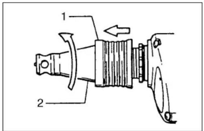
Removing or installing locator assembly (Fig. 1)
To remove the locator assembly, pull the locking sleeve forward and then turn it counterclockwise. To install the locator assembly, screw it clockwise and then push the locking sleeve back in lightly toward the motor. Turn the locking sleeve slightly to match the locking positions and then push in firmly to lock the locator in place.
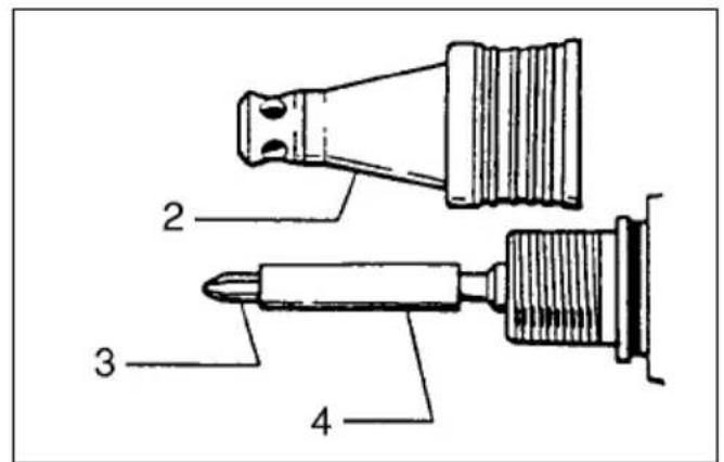
Removing or installing bit (Fig.2)
Important:
Always be sure that the tool is switched off and unplugged before removing or installing the bit.
After removing the locator assembly, pull firmly to remove the magnetic bit holder. Hold the magnetic bit holder in your hand and grasp the bit with a pair of pliers. Pull the bit out of the magnetic bit holder. Sometimes, it helps to wiggle the bit with the pliers as you pull. To install the bit, follow the removal procedures in reverse.
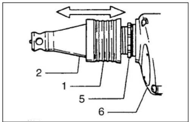
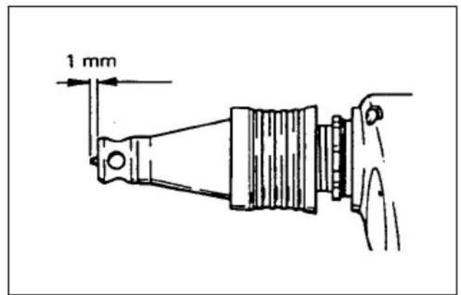
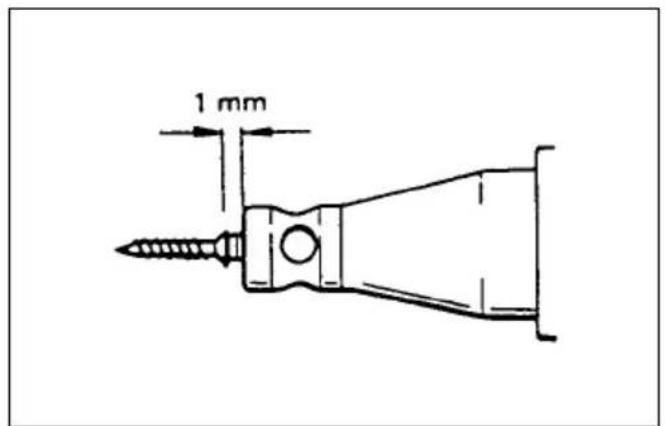
Depth adjustment (Fig.3,4 & 5)
Pull the locking sleeve forward and then turn it to adjust the depth.
Initially, adjust the locator assembly to create a distance of approximately 1mm from the tip of the locator to the base of the screw head. One full turn of the locator equals 1.5mm change in depth. After adjusting the locator assembly, push the locking sleeve in to lock the locator in place. Drive a trial screw into your material or a piece of duplicate material. If the depth is not suitable for the screw, continue adjusting until the proper depth setting is obtained.
Switch action
CAUTION:
Before plugging in the tool, always check to see that the switch trigger actuates properly and returns to the "OFF" position when released.
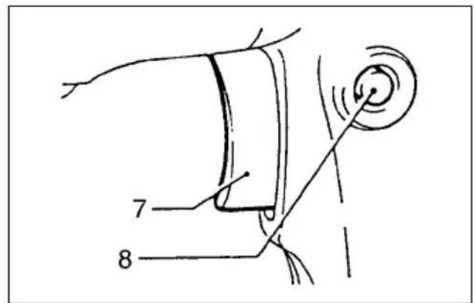
For Model 6800DB, 6801DB (Fig.6)
To start the tool, simply pull the trigger. Release the trigger to stop. For continuous operation, pull the trigger and then push in the lock button. To stop the tool from the locked position, pull the trigger fully, then release it.
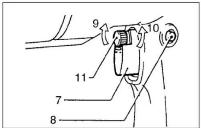
For Model 6800DBV, 6801DBV (Fig. 7)
To start the tool, simply pull the trigger. Tool speed is increased by increasing pressure on the trigger. Release the trigger to stop. For continuous operation, pull the trigger and then push in the lock button. To stop the tool from the locked position, pull the trigger fully, then release it. A speed control screw is provided so that maximum tool speed can be limited (variable). Turn the speed control screw clockwise for higher speed, and counterclockwise for lower speed.
NOTE:
Even with the switch on and motor running, the bit will not rotate until you fit the point of the bit in the screw head and apply forward pressure to engage the clutch.
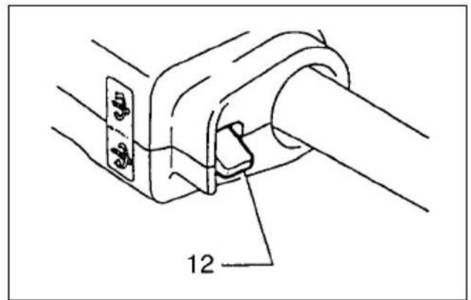
Reversing switch action (Fig.8)
CAUTION:
- Always check the direction of rotation before operation.
- Use the reversing switch only after the tool comes to a complete stop. Changing the direction of rotation before the tool stops may damage the tool.
This tool has a reversing switch to change the direction of rotation. Move the reversing switch lever to the ⏻ position for clockwise rotation or the ⏻ position for counterclockwise rotation.
Operation
For Model 6800DB, 6801DB
Fit the screw on the point of the bit and place the point of the screw on the surface of the workpiece to be fastened. Apply pressure to the tool and start it. Withdraw the tool as soon as the clutch cuts in.
For Model 6800DBV, 6801DBV
Fit the screw on the point of the bit and place the point of the screw on the surface of the workpiece to be fastened. Apply pressure to the tool. Start the tool slowly and then increase the speed gradually. Withdraw the tool as soon as the clutch cuts in.
CAUTION:
- Use the proper bit for the head of the screw that you wish to use.
- When fitting the screw onto the point of the bit, be careful not to push in on the screw. If the screw is pushed in, the clutch will engage and the screw will rotate suddenly. This could damage a workpiece or cause an injury.
- Do not continue unnecessary clutching operation.
NOTE:
Make sure that the bit is inserted straight in the screw head, or the screw and/or bit may be damaged.
MAINTENANCE
CAUTION:
Always be sure that the tool is switched off and unplugged before carrying out any work on the tool.
To maintain product safety and reliability, repairs, maintenance or adjustment should be carried out by Makita Authorized Service Center.
Noise and Vibration of Model 6800DBV
The typical A-weighted noise levels are
sound pressure level: 86 dB (A)
sound power level: 99 dB (A)
Wear ear protection. —
The typical weighted root mean square acceleration value is not more than 2.5 m/s^2 .
Noise and Vibration of Model 6801DBV
The typical A-weighted noise levels are
sound pressure level: 86 dB (A)
sound power level: 99 dB (A)
- Wear ear protection. -
The typical weighted root mean square acceleration value is not more than 2.5 m/s^2 .
EC-DECLARATION OF CONFORMITY
The undersigned, Yasuhiko Kanzaki, authorized by Makita Corporation, 3-11-8 Sumiyoshi-Cho, Anjo,
Aichi, 446-8502 Japan declares that this product
(Serial No.: series production)
manufactured by Makita Corporation in Japan is in compliance with the following standards or standardized documents,
HD400, EN50144, EN55014, EN61000
in accordance with Council Directives, 73/23/EEC, 89/336/EEC and 98/37/EC.
Yasuhiko Kanzaki
CE94

Director
MAKITA INTERNATIONAL EUROPE LTD.
Michigan Drive, Tongwell, Milton Keynes,
Bucks MK15 8JD, ENGLAND
Übersicht
HD400, EN50144, EN55014, EN61000.
Yasuhiko Kanzaki
CE94

Direktor
MAKITA INTERNATIONAL EUROPE LTD.
Michigan Drive, Tongwell, Milton Keynes,
Bucks MK15 8JD, ENGLAND
Michigan Drive, Tongwell, Milton Keynes, Bucks MK15 8JD, ENGLAND
Michigan Drive, Tongwell, Milton Keynes,
Bucks MK15 8JD, ENGLAND
Makita Corporation
Anjo, Aichi, Japan
883050A200