
MI 2603 - Cooker Meireles - Free user manual and instructions
Find the device manual for free MI 2603 Meireles in PDF.


User questions about MI 2603 Meireles
0 question about this device. Answer the ones you know or ask your own.
Ask a new question about this device
Download the instructions for your Cooker in PDF format for free! Find your manual MI 2603 - Meireles and take your electronic device back in hand. On this page are published all the documents necessary for the use of your device. MI 2603 by Meireles.
USER MANUAL MI 2603 Meireles
natural_image
Simple line drawing of two hands crossed with a diagonal line (no text or symbols)text_image
9 ⊖⊕ ⊕ 9 ⊖⊕ ⊕ ⊖⊕ r ⊖⊕ ⊕ 0 ⊖⊕ ⊕Bloqueamento
chemical
Diagram showing electron configuration symbols for negative and positive ions in a molecular structurenatural_image
Line drawing of a hand holding a pen, writing on paper (no text or symbols present)Fig. 2
text_image
30mm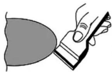
natural_image
Illustration of a hand holding a tool interacting with a curved object (no text or symbols present)Fig. 5
natural_image
Simple line drawing of a box with two crossed X marks, no text or symbols presentFig. 6
natural_image
Simple line drawing of a cooking pot with crossed x-marks (no text or symbols)Fig. 6
natural_image
Diagram of a U-shaped magnet attracting magnetic field lines around a cylindrical component (no text or symbols)Fig. 7
4 PÓS VENDA
natural_image
Simple line drawing of two hands crossed with a diagonal line (no text or symbols)text_image
Diagram showing electrical symbols and polarity labels, including plus, minus, and neutral circles with accompanying icons.text_image
9 ⊖ ⊕ ⊕ 9 ⊖ ⊕ ⊙ ⊕ r ⊖ ⊕ ⊕ ⊕ 0 ⊖ ⊕ ⊕Bloqueo
chemical
Diagram showing electron configuration symbols for positive and negative charges in a molecular structurenatural_image
Illustration of a hand holding a pen or ruler over a sheet of paper, with no visible text or symbols.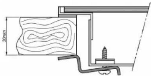
text_image
30mm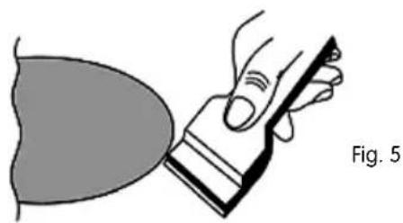
natural_image
Illustration of a hand holding a tool near a curved object, labeled 'Fig. 5' (no text or symbols on the diagram itself)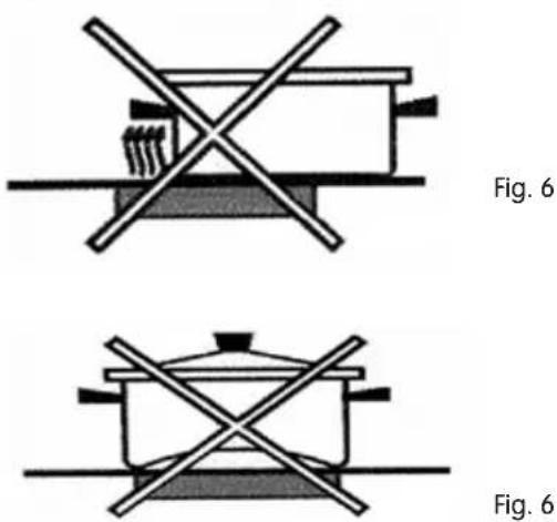
text_image
Fig. 6 Fig. 6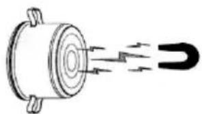
natural_image
Diagram of a U-shaped magnet attracting magnetic field lines around a cylindrical component (no text or symbols)Fig. 7
4 POSTVENTA
1 SAFETY INSTRUCTIONS 31
1.1. POWER SUPPLY 31
1.2. POWER SUPPLY CABLE AND OTHER CABLES 31
1.3. HUMIDITY AND WATER 32
1.4. CLEANING 32
1.5. GENERAL PRECAUTIONS 32
1 SAFETY INSTRUCTIONS
 | WARNING |  |
| Electric shock riskDo not open | ||
| Warning: do not remove the cover to avoid the risk of electric shock. There are no parts inside that can be repaired by the user. Request assistance from qualified personnel. | ||
Important Notices
Read this instruction manual carefully before using this appliance and keep it safe, as it might be needed for future reference.
Before turning on your appliance and ensure that it is used correctly by not operating it if:
- It has been dropped;
- You see any signs of damage;
- Any anomalies arise during operation;
It is recommended to read the instructions carefully to avoid hazards and to prevent your appliance from being damaged by incorrect use.
Your appliance must not be used for any purpose other than that envisaged in the instruction manual. It is only designed to be safe for domestic use, not commercial use. Incorrect use is not covered by the warranty and will void it automatically.
Assistance
If a fault occurs, ensure that your appliance is repaired by a qualified technician.
DO NOT ALLOW CHILDREN TO USE ELECTRICAL APPLIANCES WITHOUT SUPERVISION. DO NOT ALLOW CHILDREN OR ADULTS WITH REDUCED PHYSICAL, SENSORY OR MENTAL ABILITIES, OR PEOPLE WITH A LACK OF EXPERIENCE / KNOWLEDGE, TO USE ELECTRICAL APPLIANCES UNSUPERVISED.
1.1. POWER SUPPLY
1 Check that the electricity power supply voltage is compatible with that indicated on the appliance. If it is not compatible, consult an authorised service centre or our customer support service.
1.2. POWER SUPPLY CABLE AND OTHER CABLES
Disconnect your device whenever it is not being used.
Do not roll up the cable, pull on it to unplug the appliance or use it to wrap up the product. Keep the cable away from heated surfaces.
Never use this appliance if its cable or plug are damaged, or if it is operating incorrectly. If the power cable is damaged, do not use your appliance and take it to an authorised technical assistance centre to be replaced.
1.3. HUMIDITY AND WATER
Do not allow water to pool on your appliance, as this could be dangerous. TO AVOID DANGER OF FIRE OR ELECTRIC SHOCK, DO NOT EXPOSE THE APPLIANCE TO WATER OR HUMIDITY. Do not place the appliance under water (for example, for washing).
1.4. CLEANING
- Let the hob cool and clean it completely, as dirt can be very difficult to remove when reheated.
- Use products that are suitable for cleaning glass-ceramic hobs.
- Do not use abrasive sponges or powder detergents that could scratch the glass surface.
- Do not use oven cleaning spray, as it is very aggressive and could damage the glass surface.
- The glass-ceramic hob should not be cleaned using steam or other similar methods.
- To remove minor dirt, use hot water and a little detergent, rinse with clean water and dry with a soft cloth or paper.
- Remove any residual detergent, as it could damage the glass when hot.
- The use of an adequate spatula for cleaning glass is recommended for severe build-ups (see figure 51).
- Warning: If plastic objects, sugar or sugary foods melt onto the hob, they should be removed while hot using a spatula, taking care to avoid getting burnt.
1.5. GENERAL PRECAUTIONS
- The appliance must be installed by a technically qualified person with knowledge of current installation standards and regulations.
- This instruction manual should always accompany the product if it is transferred to another owner.
- Children should be supervised whenever using the hob to ensure that they do not touch the hot surfaces or get too close to the appliance during use.
- Disconnect the appliance from the electricity supply and wait until it is completely cold before performing any maintenance operations.
- The hob's power supply cable must not be replaced by the user. This operation must only be performed by competent technical personnel.
- Should repairs be necessary, always contact an authorized technical assistance centre and demand original parts.
- Repairs made by incompetent personnel may cause damage.
WARNING: If the surface is broken, disconnect the appliance by turning off the power supply protection device, to avoid the possibility of an electric shock.
The hob has been designed to not interfere with the operation of other pieces of electrical equipment, provided that they respect the rules that apply to them.
The induction hob creates magnetic fields in its vicinity.
To ensure that no interferences are generated between the hob and pacemakers, the pacemaker must have
been designed as per applicable standards
However, we recommend that anyone using pacemaker style devices should consult with their doctor or device manufacturer about possible incompatibilities of the device*
If in doubt, an induction hob should not be used*
2 USE AND OPERATION
2.1.
INSTALLATION
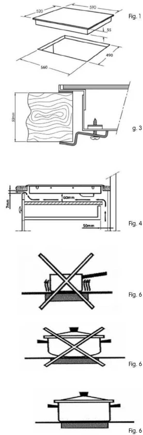
Cut the work area, as per the measurements indicated in figure 1
The hob should be installed on a completely flat surface to avoid the risk of breaking the glass
Any reinforcements in the installation area must be removed*
Insert the hob into the opening in the furniture such that it is centralised*
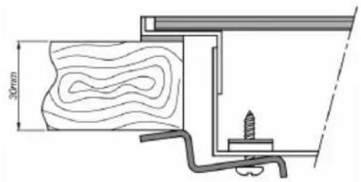
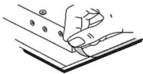
To prevent seepage, apply the supplied sealant around the entire edge of the hob, ensuring that the ends touch without overlapping (see figure 2).
Do not use silicone to seal the hob, as this will make it impossible to remove if maintenance is required in the future.
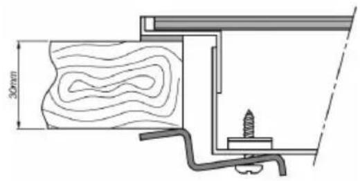
Fix the hob in place with the supplied clamps.
Bolts should be tightened sufficiently to fix the hob in place (see figure 3).
The hob should be installed at a minimum distance of 50 mm from the rear wall and 100 mm from side walls.
If any furniture is suspended above the work area, it must be at minimum height of 600 mm above it.
If there is a piece of furniture higher than the hob, it must be at a minimum distance of 300 mm away.
Combustible materials, such as curtains, should be at a minimum distance of 500 mm away.
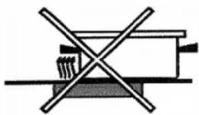
If the hob is installed above a drawer, there must be a division between the bottom of the hob and the drawer to avoid accidental contact with the hot base of the hob.
As a minimum, the hob must be installed at a height of 60 mm above the division or the oven installed immediately below it (see figure 4).
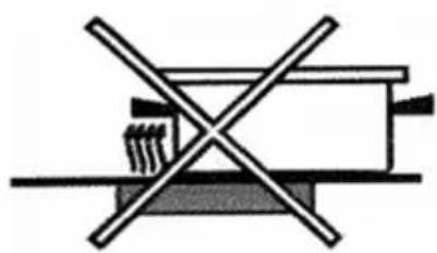
When installing the hob, the ventilation spaces described in figure 4 must be planned.
Specifically, there must be an air outlet with a height of at least 7 mm at the front along the entire length of the hob, and an air inlet at the rear of the furniture with a height of at least 50 mm along the entire length of the hob.
The fresh air inlet and hot air outlets are fundamental for the correct and effective operation of the induction hob.
2.2 ELECTRICAL CONNECTION
The appliance's electrical connection must be made by a qualified person, in accordance with current safety standards.
Before turning the hob on, make sure that the electrical connections and protection devices are suitable for the product's technical characteristics.
Before turning the appliance on, make sure that the domestic electricity installation and circuit breaker can withstand its load (see the appliance's data plate).
If the hob is installed above an oven, the electrical connections of the two appliances must be made separately, both to facilitate their extraction and for electrical safety reasons.
To connect the hob to the electricity supply, an all-pole circuit breaker must be installed between the oven and the power supply, with a minimum gap between the contacts of 3mm. This circuit breaker should be appropriate for the load and correspond to current safety regulations.
The earth cable, identifiable by its green/yellow colours, must not run through the switch.
The power supply cable must be positioned such that none of its points can reach a temperature in excess of 50^ C above room temperature.
It should also be ensured that the power supply installation is properly earthed, in accordance with current safety standards, and that the all-pole circuit breaker is accessible when the hob is installed.
Do not use shortened cables, bypasses or adaptors, as these could cause overheating and pose a fire risk.
The manufacturer shall not be liable if current standards are not followed, and shall not be considered liable for damage and/or injury resulting from incorrect installation and/or use.
2.3. USE
If the glass breaks, disconnect the hob from the electricity supply.
Food wrapped in aluminium foil cannot be cooked directly on the glass.
Each work area is marked by an outline.
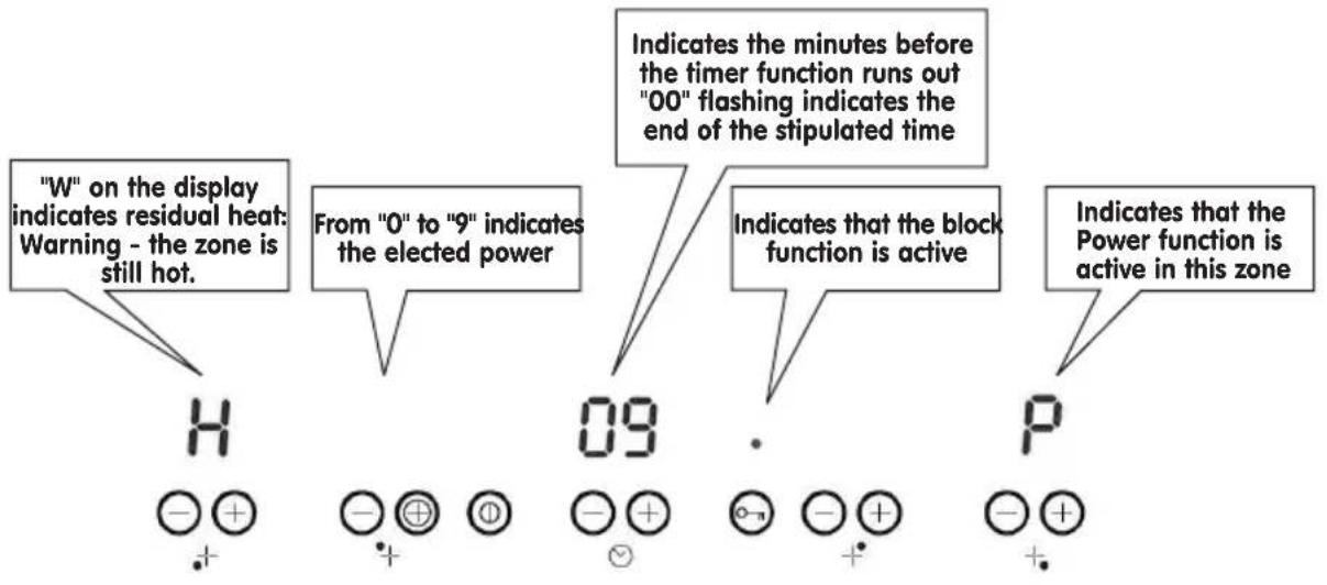
For cooking that does not require intense heat, take advantage of residual heat in the heating zones, digit "Non the display.
Save energy by boiling liquids at the lowest possible power level.
Do not leave any objects on the hob's cooking zone, even if it is turned off.
2.4. COOKWEAR
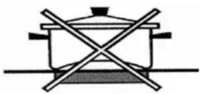
Induction zones only work with cookwear with ferromagnetic bases.
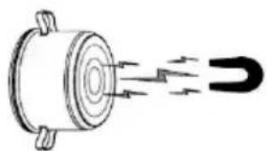
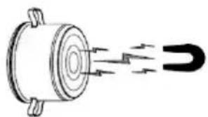
Cookwear is ferromagnetic if a magnet is attracted to their base, and can thus be used on induction heating zones, see figure 7.
Cookwear with thick bases and diameters similar to that of the heating area must be used.
To avoid scratching the glass, cookwear must not have rough bases and must be clean and dry before being placed on the glass-ceramic hob.
If unsuitable cookwear is used, the thermostat will deactivate before the required temperature is reached.
This will prolong cooking times and waste energy.
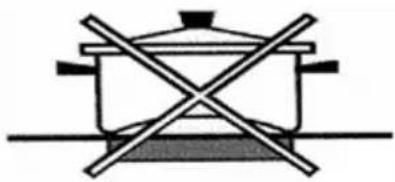
It is recommended to cover cookwear while cooking. This saves a considerable amount of energy.
We recommend the use of stainless steel cookwear with a flat base with good heat conductivity, as this allows cooking times to be reduced.
Aluminium and copper cookwear is not recommended, as they can stain the glass surface.
Induction zones are fitted with a pan detection system.
The induction zones will not work if the pan placed on them is not of a certain minimum size.
| Minimum cookwear diameters | |
| Zones 2 & 4 Zones 1 & 3 | |
| 9 cm 13 cm | |
If it is attempted to turn on a zone without a pan, or with a pan that is too small, the fault indicator "U" will be displayed, or the display will flash.
When cooking is complete, turn off the zones using the "Off" sensor on the digital control panel.
The aforementioned diameters refer to cookwear with good induction characteristics.
Recipients with weak induction capacity may require a diameter of up to 35% more
2.5. SENSORS
This appliance is fitted with electronic sensors, which are activated by placing your finger over the symbols. Please remember that only one sensor may be used at a time, except when a zone is turned off by pressing the "+" and "-" sensors at the same time.
Never place objects in the sensor zone; the sensor zone must remain clear to prevent errors from occurring. If an error occurs, all zones will be turned off and the residual heat indicators activated.
natural_image
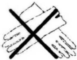
Simple line drawing of two hands crossed with a diagonal line (no text or symbols)Do not use gloves to touch the sensors
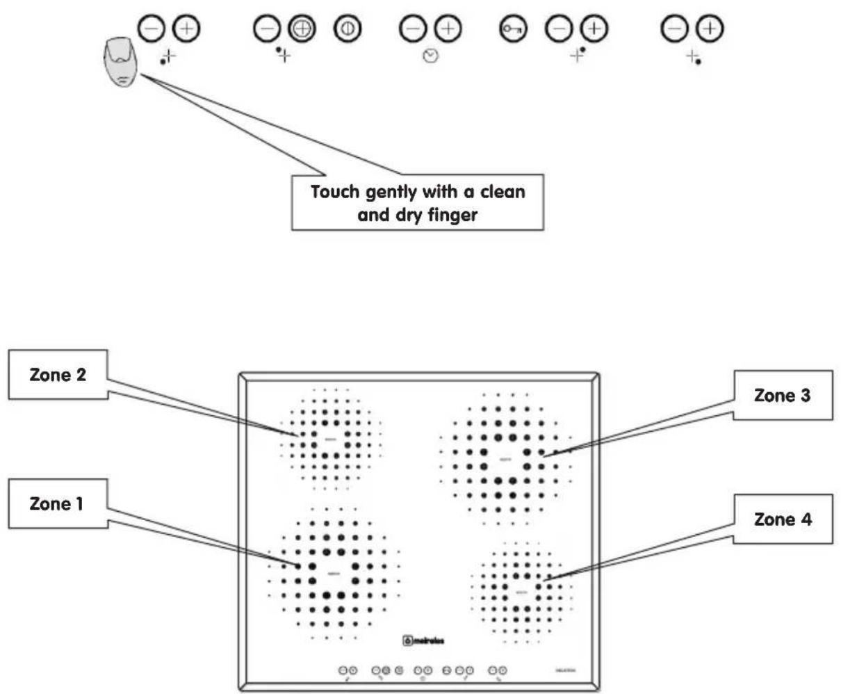
Sensors should be touched gently with a clean and dry finger
text_image
Touch gently with a clean and dry finger Zone 2 Zone 1 Zone 3 Zone 4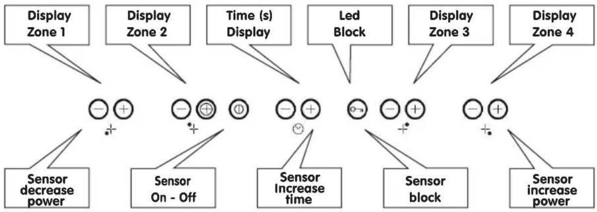
flowchart
graph TD
    A["Display Zone 1"] --> B["Sensor decrease power"]
    C["Display Zone 2"] --> D["Sensor On - Off"]
    E["Time (s) Display"] --> F["Sensor Increase time"]
    G["Led Block"] --> H["Sensor block"]
    I["Display Zone 3"] --> J["Sensor increase power"]
    K["Display Zone 4"] --> L["Sensor increase power"]
 | Turns the hob on:All displays show "0" and a flashing decimal point.Turns the hob off:The display indicates "H" for residual heat if the zone is still hot.If no zone is selected within 10 seconds, the hob turns itself off automatically | |
 | SensorOn - Off | |
 | Increase to:Increase the power level.When operated simultaneously with the decrease sensor, this turns the zone off | |
 | Sensorincreasepower | |
 | Decrease to:Decrease the power level.When operated simultaneously with the increase sensor, this turns the zone off | |
 | Sensordecreasepower | |
 | Block to:Block the use of sensors while cooking.Block the use of sensors when the hob is turned off, so that it is not turned on accidentally (children, cleaning).The sensor must be touched continuously for 3 seconds to turn this function on.Even when the block function has been activated, it is still possible to turn the zones off one by one, and to turn the entire hob off simultaneously. | |
 | BlockSensor | |
 | Increase time to:Increase the countdown time.When operated simultaneously with the decrease sensor, this turns off the timer function. | |
 | Sensorincreasetime |
text_image
"W" on the display indicates residual heat: Warning - the zone is still hot. From "0" to "9" indicates the elected power Indicates the minutes before the timer function runs out "00" flashing indicates the end of the stipulated time 09 Indicates that the block function is active Indicates that the Power function is active in this zone2.6. USE
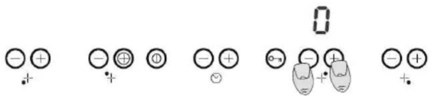
Turn off a plate
When a plate is operating, the zones can be turned off by pressing the (-) and (+) keys simultaneously.
"0" is displayed and an audio signal is heard.
text_image
Diagram showing electrical symbols and polarity labels, including plus, minus, and neutral circles with accompanying icons.2.7.
ACTIVATE POWER FUNCTION (BOOSTER ZONE)
All of the zones have a "power increase" power level. Select the desired zone and use the (-) sensor to turn it up to level 9.
By pressing the (+) sensor for the selected zone, a "P" is displayed for "power function active"
The power function will only operate for the first 10 minutes, after which it will go back to level 9.
Powers
| Level Zones 1 and 3 Zones 2 and 4 | ||
| P 2000 W 1600 W | ||
| 9 1800 W 1200 W | ||
| 8 1300 W 1000 W | ||
| 7 1100 W 800 W | ||
| 6 900 W 600 W | ||
| 5 800 W 500 W | ||
| 4 500 W 400 W | ||
| 3 300 W 300 W | ||
| 2 200 W 150 W | ||
| 1 100 W | 75 W | |
Selecting the Power
This plate has an "Eco power limit" system.
The user can reduce the plate's total power
The maximum power when the plate is turned on is 7200 W. This can be reduced by the user to 2800W, 3500W or 6000W.
Selecting Eco power limits
The following sequence is used to choose a new power limit:
- during the first 30 seconds after the appliance has been turned on
- The hob must be unblocked and all zones turned off
- press the (-) and (+) keys of zones 1 and 4 simultaneously.
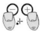
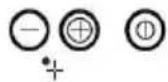

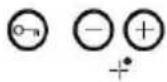
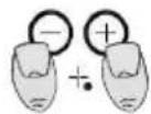
Doing this causes a signal to sound, " P_0 " appears on the timer display and the current power limit will be shown on the zone 1 and zone 4 displays (7200W).
To select a new power limit:
Sensors (+) and (-) are used to choose the power limit. The following powers can be selected: 2800W, 3500W, 6000W, 7200W. If the (+) and (-) sensors are pressed when the power is at 7200W, the power changes to 2800W.
The following sequence is used to finish setting the new power limit:
- press the (-) and (+) keys of plates 1 and 4 simultaneously.
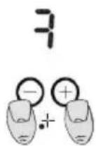
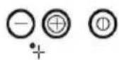

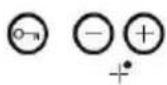

- once some, the new power is set and the system is not re-set.
To exit without changing the setting:
if no action is taken for 60 seconds, the changes are not set and the system is restarted.
Plate power limit
The plate's total power level is calculated whenever the user attempts to increase the power. If this total power level is in excess of the plate's pre-set power limit, the power increase is not permitted, an error beep sounds and the display shows "r" for 3 seconds.

text_image
9' -⊕ + + + ⊕ ⊙ -⊕ -⊕ r 0 -⊕ + + ⊙ -⊕ -⊕ + +Blocking
press the block sensor (key) for 3 seconds to activate or deactivate the blocking function. If the key symbol is shown, the hob is not blocked.

chemical
Diagram showing electron configuration symbols for positive and negative ions in a molecular structure2.8. TIME LIMIT IN OPERATION
For safety reasons, the zone deactivates automatically when a certain maximum operating time is exceeded. The maximum operating time depends on the level selected for the zone:
| level 1-10 hours level 4-10 hours level 7-10 hours | |
| level 2-10 hours level 5-10 hours level 8-10 hours | |
| level 3-10 hours level 6-10 hours level 9-3 hours |
The time value can be selected between 1 and 99 minutes, and it is possible to set the time for a zone at any power level (0 .. 9); the user can only select one zone at a time for the timer function.
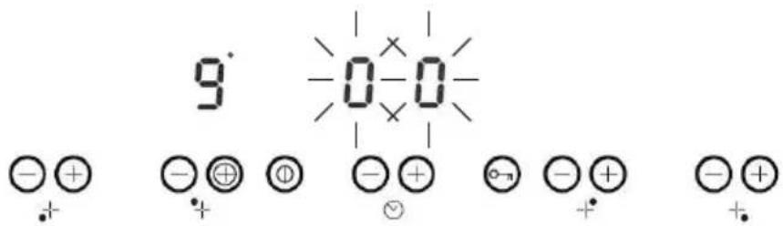
Activate Timer:
Press the timer sensor (+) or (-). A noise sounds and the display shows a 00 "time" symbol. The displays show a flashing "1", indicating that the timer has been activate for the zone in question.
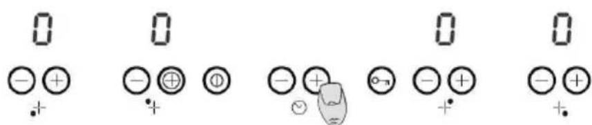
text_image
0 - + - ⊕ - + - + - + + + + + +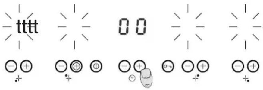
text_image
- tttt 0 0 - + - + + - + - + - + - +Select a zone with time
When the timer is awaiting the selection of a zone, the zone can be selected by pressing the selector of the desired zone. A sound plays and the plate's display flashes to indicate that the power has not been selected for the plate in question.
The timer display starts to flash to indicate that the time has to be selected.
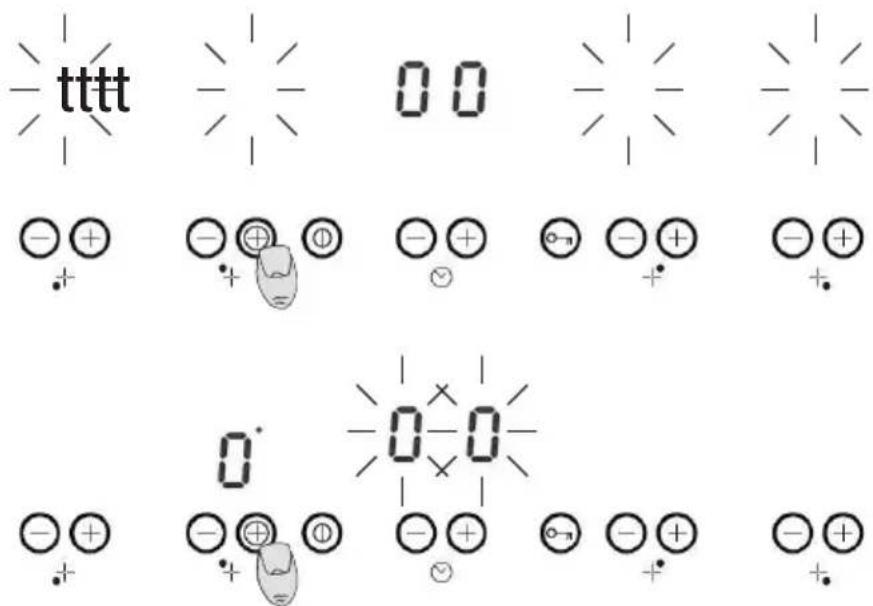
text_image
tttt 00 0 0 0-0 -+ + + -+ + -+ + -+ + + -+ + + -+ + + -+ + + -+ + + -+ + + -+ + + -+ + + -+ + + -+ + + -+ + + -+ + + -+ + + -+ + + -+ + + -+ + + -+ + + -+ + + -+ + + -+ + + -+ + + -+ + + -+ + + -+ + + -+ + + -+ + -+ + + -+ + -+ + -n -n -n -n -n -n -n -n -n -n -n -n -n -n -n -n -n -n -n -n -n -n -n -n -n -n -n -n -n -n -n -n -n -n -n -n -n -n -n -n -n -n -n -n -n -n -n -n -n -n -m -+ + + 0-0 -+ + + 0-0 -+ + + 0-0 -+ + + 0-0 -+ + + 0-0 -+ + + 0-0 -+ + + 0-0 -+ + + 0-0 -+ + + 0-0 -+ + + 0-0 -+ + + 0-0 -+ + + 0-0Only one zone can be chosen at a time.
Set the desired power level
Use the (+) sensor to select the desired power
text_image
9 -0-0 -⊕⊕⊕ -⊕ -⊕ -⊕ -⊕Set the desired time on the timer with the (+) and (-) buttons
3 IMAGES
natural_image
Line drawing of a hand holding a pen, writing on paper with no visible text or symbolsFig. 2
text_image
30mm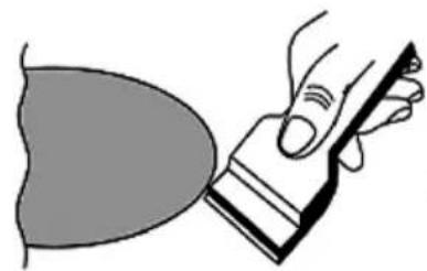
natural_image
Illustration of a hand holding a tool interacting with a curved object (no text or symbols present)Fig. 5
natural_image
Simple line drawing of a box with two crossed X marks, no text or symbols presentFig. 6
natural_image
Simple line drawing of a cooking pot with crossed panes (no text or symbols)Fig. 6
natural_image
Diagram of a U-shaped magnet attracting magnetic field lines around a cylindrical component (no text or symbols)Fig. 7
4 AFTER-SALES
Meireles designed this appliance to guarantee maximum flexibility.
Do not open the appliance - risk of electric shock.
Contact the closest service centre if you are not able to solve the problem
WARNING: Any attempt to fix the appliance without contacting the manufacturer will void the warranty.
If the problem persists, take your appliance to an after-sales office to solve the problem.
Meireles provides a warranty against any manufacturing defects that are found during a period of 2 years after the purchase date of this appliance. A condition of the warranty is the correct use and maintenance of the article, specifically in accordance with the instructions set out in this manual. If these conditions are not met, the fault will not be covered by the warranty.
Repairs to electrical appliances must only be made by specialist technicians, as subsequent complications may arise in the appliances if the work is not done by such a technician.
To avoid unnecessary hazards, if faults occur in the cables or any other type of component, repairs must be made at specialist service centres, as appropriate tools are required.
5 ENVIRONMENTAL CONSERVATION
We attempt to reduce the volume of packaging as much as possible and limit it to three materials that are easy to separate: cardboard, paper and plastic.
The appliance is made from recyclable material, once dismantled by a specialised company. Comply with local legislation.
The manufacturer reserves the right to make changes to the appliances. These changes will not affect the operation or safety of the appliances.
INDEX
natural_image
Simple line drawing of two hands crossed with a diagonal line (no text or symbols)chemical
Atomic structure diagrams of ionic elements showing 9, 0, r, and negative charges with electron delocalizationSperrung
chemical
Diagram showing electron configuration symbols for negative and positive ions in a molecular structurenatural_image
Illustration of a hand cutting down a piece of paper with a ruler, labeled 'Bild 2' (no text or symbols on the diagram itself)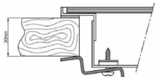
text_image
30mm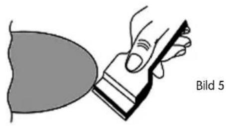
natural_image
Illustration of a hand holding a tool near a curved surface, labeled 'Bild 5' (no text or symbols on the diagram itself)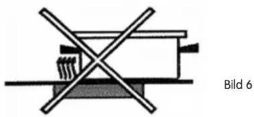
natural_image
Diagram showing a cross-shaped object with crossed lines, no text or symbols present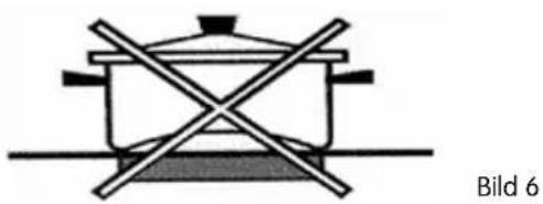
natural_image
Simple line drawing of a cooking pot with crossed x marks, no text or symbols present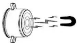
natural_image
Diagram of a mechanical component with magnetic field lines indicating direction (no text or symbols)Bild 7