
F-15 Eagle - Remote control toy E-flite - Free user manual and instructions
Find the device manual for free F-15 Eagle E-flite in PDF.


| Product Type | Radio-controlled (RC) electric ducted fan (EDF) jet model aircraft |
| Brand | E-flite |
| Model | F-15 Eagle 64mm EDF |
| Motor | Brushless Outrunner 2840-3150Kv (EFL9787) |
| Electronic Speed Control (ESC) | 40A Brushless ESC (EFL9791) |
| Recommended Battery | 11.1V–14.8V 3S–4S 2200–2600mAh 30C Li-Po (e.g., EFLB22003S30 or EFLB22004S30) |
| Receiver (BNF Basic) | Spektrum AR636 6-Channel Sport Receiver with AS3X and SAFE Select |
| Servos | (4) 9-gram servos (positive, reverse, and steering) |
| Technology | SAFE Select (enabling/disabling during bind) and AS3X stabilization |
| Center of Gravity (CG) | 88mm ±3mm back from leading edge of wing at root |
| Control Throws (Low Rate / High Rate) | Aileron: 12mm / 15mm; Elevator: 14mm / 18mm |
| Flight Timer Setting | 3 minutes (recommended initial flight time with 3S 2200mAh battery) |
| Recommended Transmitter | Full-range 6+ channel 2.4GHz with Spektrum DSM2/DSMX, adjustable dual rates |
| Age Recommendation | 14 years and up (not a toy) |
| Material | EPO foam |
| Power Type | Electric ducted fan (64mm EDF) |
| Assembly Required | Yes (wing, stabilizers, landing gear, missiles) |
| Spare Parts Availability | Yes – fuselage, wings, stabilizers, nose cone, canopy, landing gear, motor, servos, fan unit, etc. |
| Warranty | Limited warranty against defects in materials and workmanship (see manual for details) |
| Safety Precautions | Keep safe distance; avoid water; always use fully charged batteries; remove batteries after flight; read entire manual before use. |
| Post-Flight Maintenance | Disconnect flight battery, power off transmitter, remove battery, recharge, inspect for damage, store battery separately. |
Frequently Asked Questions - F-15 Eagle E-flite
User questions about F-15 Eagle E-flite
0 question about this device. Answer the ones you know or ask your own.
Ask a new question about this device
Download the instructions for your Remote control toy in PDF format for free! Find your manual F-15 Eagle - E-flite and take your electronic device back in hand. On this page are published all the documents necessary for the use of your device. F-15 Eagle by E-flite.
USER MANUAL F-15 Eagle E-flite
All instructions, warranties and other collateral documents are subject to change at the sole discretion of Horizon Hobby, LLC. For up-to-date product literature, visit www.horizonhobby.com and click on the support tab for this product.
Meaning of Special Language
The following terms are used throughout the product literature to indicate various levels of potential harm when operating this product:
WARNING: Procedures, which if not properly followed, create the probability of property damage, collateral damage, and serious injury OR create a high probability of superficial injury.
CAUTION: Procedures, which if not properly followed, create the probability of physical property damage AND a possibility of serious injury.
NOTICE: Procedures, which if not properly followed, create a possibility of physical property damage AND little or no possibility of injury.

WARNING: Read the ENTIRE instruction manual to become familiar with the features of the product before operating. Failure to operate the product correctly can result in damage to the product, personal property and cause serious injury.
This is a sophisticated hobby product. It must be operated with caution and common sense and requires some basic mechanical ability. Failure to operate this Product in a safe and responsible manner could result in injury or damage to the product or other property. This product is not intended for use by children without direct adult supervision. Do not use with incompatible components or alter this product in any way outside of the instructions provided by Horizon Hobby, LLC. This manual contains instructions for safety, operation and maintenance. It is essential to read and follow all the instructions and warnings in the manual, prior to assembly, setup or use, in order to operate correctly and avoid damage or serious injury.
14+
AGE RECOMMENDATION: Not for children under 14 years. This is not a toy.

WARNING AGAINST COUNTERFEIT PRODUCTS: If you ever need to replace your Spektrum receiver found in a Horizon Hobby product, always purchase from Horizon Hobby, LLC or a non-Hobby authorized dealer to ensure authentic high-quality Spektrum product. Horizon Hobby, LLC aims all support and warranty with regards, but not limited to, compatibility and performance of counterfeit products or products claiming compatibility with DSM or Spektrum technology.
Safety Precautions and Warnings
As the user of this product, you are solely responsible for operating in a manner that does not endanger yourself and others or result in damage to the product or the property of others.
- Always keep a safe distance in all directions around your model to avoid collisions or injury. This model is controlled by a radio signal subject to interference from many sources outside your control. Interference can cause momentary loss of control.
- Always operate your model in open spaces away from full-size vehicles, traffic and people.
- Always carefully follow the directions and warnings for this and any optional support equipment (chargers, rechargeable battery packs, etc.).
- Always keep all chemicals, small parts and anything electrical out of the reach of children.
- Always avoid water exposure to all equipment not specifically designed and protected for this purpose. Moisture causes damage to electronics.
-
Never place any portion of the model in your mouth as it could cause serious injury or even death.
-
Never operate your model with low transmitter batteries.
• Always keep aircraft in sight and under control.
• Always use fully charged batteries.
• Always keep transmitter powered on while aircraft is powered.
• Always remove batteries before disassembly.
• Always keep moving parts clean.
• Always keep parts dry.
• Always let parts cool after use before touching.
• Always remove batteries after use. - Always ensure failsafe is properly set before fl ying.
- Never operate aircraft with damaged wiring.
- Never touch moving parts.
Box Contents
| Quick Start Information | |||
| Transmitter Setup | Set up your transmitter using the transmitter setup chart | ||
| Travel and Dual Rates | Hi Rate Low Rate | ||
| Aileron 15 | mm 12mm | ||
| Elevator | 18mm | 14mm | |
| Center of Gravity (CG) | 88mm +/-3mm back from leading edge of wing at the fuselage. | ||
| Flight Timer Setting | 3 minutes | ||

natural_image
Technical line drawing of a fighter jet with multiple aircraft wings and structural components (no text or labels)Components
| BNF BASIC | PNP PLUG-N-PLAY | ||
 | Motor: Brushless Outrunner 2840-3150 (EFL9787) | Installed | Installed |
 | ESC: 40A ESC (EFL9791) | Installed | Installed |
 | Servo: 9 gram servo | Installed | Installed |
 | Receiver: SpektrumTM AR636 6-Channel Sport Receiver (SPMAR636) | Installed | Required to Complete |
 | Recommended Battery: 11.1-14.8V 3S or 4S 2200-2600mAh 30C Li-Po (EFLB22003S30, EFLB22004S30) | Required to Complete | Required to Complete |
 | Recommended Battery Charger: 3-4 cell Li-Po battery balancing charger | Required to Complete | Required to Complete |
 | Recommended Transmitter: Full-Range 6 channel (or more) 2.4GHz with Spektrum DSM2®/DSMX® technology with adjustable Dual Rates | Required to Complete | Required to Complete |

Table of Contents
| Safety Precautions and Warnings | 2 |
| Box Contents | 3 |
| Components | 3 |
| Table of Contents | 3 |
| SAFE® Select Technology (BNF Basic) | 4 |
| Prefl ight | 4 |
| Transmitter Setup (BNF Basic) | 4 |
| Model Assembly | 5 |
| PNP Receiver Selection and Installation | 8 |
| Transmitter and Receiver Binding / SAFE Select (BNF Basic) | 9 |
| Battery Installation and ESC Arming | 10 |
| SAFE® Select Switch Designation | 10 |
| Clevis Installation and Control Centering | 11 |
| Control Horn and Servo Arm Settings | 11 |
| Center of Gravity (CG) | 11 |
| Control Surface Direction | 12 |
| AS3X Control Direction Test (BNF Basic) | 12 |
| In Flight Trimming (BNF Basic) | 13 |
| Flying Tips and Repairs | 13 |
| Post Flight | 14 |
| Power Components Service | 14 |
| Troubleshooting Guide AS3X | 14 |
| Troubleshooting Guide | 15 |
| AMA National Model Aircraft Safety Code | 16 |
| Limited Warranty | 17 |
| Contact Information | 18 |
| FCC Information | 18 |
| IC Information | 18 |
| Compliance Information for the European Union | 18 |
| Replacement Parts | 67 |
| Optional parts | 67 |
| RECEIVER BIND INFORMATION | |
| Channels 6 | |
| Frequency 2405 – 2476 MHz | |
| Compatibility | DSM2 and DSMX |
If you own this product, you may be required to register with the FAA.
For up-to-date information on how to register with the FAA, visit https://registermyuas.faa.gov/.
For additional assistance on regulations and guidance on UAS usage, visit knowbeforeyoufl y.org/.
To receive product updates, special offers and more,
visit www.horizonhobby.com/content/e-fl ite-rc
SAFE® Select Technology (BNF Basic)
The evolutionary SAFE® Select technology can offer an extra level of protection so you can perform the first flight with confidence. No complex transmitter programming is required. Just follow the simple bind process to make the SAFE Select system active. When activated, bank and pitch limitations keep you from over-controlling and automatic self-leveling makes recovery from risky or confusing attitudes as simple as releasing the sticks. In fact, with the aileron, elevator and rudder sticks in the neutral position, SAFE Select will automatically keep the airplane in a straight and level attitude.
Expand the advantage of what SAFE® Select technology offers by assigning it to a switch. No transmitter programming is required and you'll be able to turn the system ON and OFF with the flip of a switch. For example, turn SAFE select ON for takeoffs to counter cross winds. Turn it OFF in flight for unrestricted aerobatic performance, and turn it back ON when a buddy wants to try out your cool aircraft. Turn SAFE Select ON for landings. SAFE Select reduces your workload by compensating for pitch changes automatically, regardless of throttle position. It will help keep the correct pitch attitude and wings level during the final approach. Whether you're a beginner or an expert, SAFE Select can make your flights a great experience. When the normal bind process is followed, the SAFE Select system is disabled, leaving specially tuned AS3X® technology in place to deliver a pure, unrestricted flight experience.
Preflight
| 1. Remove and inspect contents. |
| 2. Read this instruction manual thoroughly. |
| 3. Charge the fl ight battery. |
| 4. Setup Transmitter using transmitter setup chart. |
| 5. Fully assemble the airplane. |
| 6. Install the fl ight battery in the aircraft (once it has been fully charged). |
| 7. Check the Center of Gravity (CG). |
| 8. Bind the aircraft to your transmitter. |
| 9. Make sure linkages move freely. |
| 10. Perform the Control Direction Test with the transmitter. |
| 11. Perform the AS3X Control Direction Test with the aircraft. |
| 12. Adjust fl ight controls and transmitter. |
| 13. Perform a radio system Range Test. |
| 14. Find a safe open area to fl y. |
| 15. Plan fl ight for fl ying fi eld conditions. |
Transmitter Setup (BNF Basic)
Dual Rates
Take first flights in Low Rate. For landings, use high rate elevator.
NOTICE: To ensure AS3X ^® technology functions properly, do not lower rate values below 50%. If lower rates are desired, manually adjust the position of the pushrods on the servo arm.
NOTICE: If oscillation occurs at high speed, refer to the Troubleshooting Guide for more information.
Expo
After fi rst fl ights, you may adjust expo in your transmitter for each channel to fi t your fl ying style.
| Computerized Transmitter Setup | |
| Start all transmitter programming with a blank ACRO model (perform a model reset), then name the model. | |
| Set Dual Rates to | HIGH 100% |
| LOW 70% | |
| Set Servo Travel to 100% | |
| Set Throttle Cut to -130% | |
Model Assembly
Landing Gear Installation
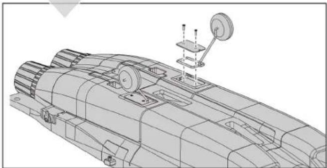
- Install the nose gear with set screws. Use thread locking compound on the set screws. The fl at spot will make the connection straight and secure.
- Install the main gear with covers using the M2x8 fl at head screws.
natural_image
Technical line drawing of a mechanical assembly with no visible text or symbols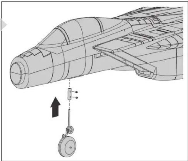
natural_image
Technical line drawing of an aircraft fuselage with a pulley and directional arrow indicating motion (no text or symbols)Wing Installation
- Slide the wing tube into the fuselage.
-
Slide the wing panels on the wing tube. Ensure the wing panels are tight against the fuselage.
-
Using a 2mm hex wrench, install 4-M3x10 fl at head screws to secure the main wing panels.
- Connect the servo leads firmly. Make sure the wires are secure in the wing using the colored decals.

natural_image
Technical line drawing of a warship or aircraft fuselage with three side views showing structural details (no text or symbols)
natural_image
Technical line drawing of a futuristic spaceship with visible structural components and no text or symbolsModel Assembly Continued
Horizontal Stabilizer Installation
- Apply regular, (not Foam Safe) medium CA to the base of the horizontal stabilizer where it meets the fuselage.
- Make sure the control horn faces down toward the bottom and fi t each horizontal stabilizer to the fuselage.
IMPORTANT! Make sure the horizontal stabilizer is in alignment with the wing. Adjust as necessary before the CA fully cures.

natural_image
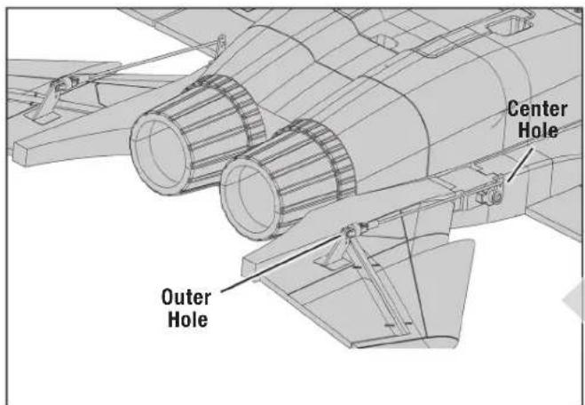
Technical illustration of a fighter jet assembly with labeled parts and directional arrows (no text or symbols)- On each side, attach the Z-bend of the elevator linkage to the center hole of the servo arm then attach the clevises to the outer hole of the elevator control horns. Slide the clevis retainer tube over the clevis to lock in place.
IMPORTANT! Adjust each pushrod clevis to make sure the travel of both elevators match and are centered.
Vertical Stabilizer Installation
- Apply medium CA to the base of the vertical stabilizers where they meet the fuselage.
- Fit the vertical stabilizer in place on the fuselage. Make sure the vertical stabilizers are straight up and down and point straight.

Model Assembly Continued
Missile Installation
- Attach the missiles on each side of the tanks using medium CA glue.
TIP: Along the line where the Missile rack and the Fuel Tank connect, use a T-Pin or Hobby Knife to poke several small holes through the paint to help the glue adhere.

flowchart
graph TD
    A["Central Device"] --> B["Mobile Device"]
    A --> C["Mobile Device"]
    A --> D["Mobile Device"]
    A --> E["Mobile Device"]
    F["Mobile Device"] --> G["Mobile Device"]
    F --> H["Mobile Device"]
    F --> I["Mobile Device"]
    F --> J["Mobile Device"]
    style A fill:#f9f,stroke:#333
    style F fill:#bbf,stroke:#333

- Attach a missile assembly onto each wing by placing them into the slot and sliding back to lock in place. Ensure the long area of the tank faces forward. No glue is required.
Nose Cone Installation
- Attach the nose cone to the airplane. The cone is held in place with the magnet. For a more secure attachment, use medium CA glue.

natural_image
Line drawing of a jet aircraft with an arrow indicating flight direction (no text or symbols)PNP Receiver Selection and Installation
The Spektrum ^™ AR636 receiver is recommended for this airplane. If you choose to install another receiver, ensure that it is at least a 4-channel full range receiver. Refer to your receiver manual for correct installation and operation instructions.
Installation (AR636 shown)
- Remove the canopy from the aircraft.
- Connect the servos to the receiver. We recommend using a short servo extension on the bind port so it is easier to reach for binding and programming.
1 = Throttle 3 = Elevator
2 = Aileron 4 = Rudder
- Mount the receiver very securely using double sided tape so it is located in front of the steering servo. Make sure it is mounted as fl at as possible with the label facing up and the wires facing back. You may need to use servo extensions for the aileron and elevator.

Transmitter and Receiver Binding / Enabling and Disabling SAFE Select (BNF Basic)
This product requires an approved Spektrum ^™ DSM2®/DSMX® compatible transmitter. Visit www.bindnfl y.com for a complete list of approved transmitters.
The aircraft has an optional SAFE Select feature, which can be switched ON or OFF easily by binding in a specific manner as described below.
IMPORTANT: Before binding a transmitter, read the Transmitter Setup section of this manual to ensure that your transmitter is properly programmed for this aircraft.
Bind Plug Installation

Binding Procedure / Switching ON SAFE Select
IMPORTANT: The included AR636 receiver has been programmed for operation specifically for this aircraft. Refer to the receiver manual for correct setup if the receiver is replaced or is used in another aircraft.

CAUTION: When using a Futaba® transmitter with a Spektrum DSM® module, you must reverse the throttle channel and rebind. Refer to your um module manual for binding and failsafe instructions. Refer to your transmitter manual for instructions on reversing the throttle channel.
- Make sure the transmitter is powered off.
- Move the transmitter controls to neutral (flight controls: rudder, elevators and ailerons) or to low positions (throttle, throttle trim).*
- Install a bind plug in the receiver bind port.
- Place the aircraft level on its wheels, then connect the fl light battery to the ESC. The ESC will produce a series of sounds. Three fl at tones followed immediately by two ascending tones confi rm that the LVC is set correctly for the ESC. The orange bind LED on the receiver will begin to fl ash rapidly.
- Remove the bind plug from the bind port.
- Take three steps away from the aircraft /receiver and then power ON the transmitter while holding the transmitter bind button or switch. Refer to your transmitter's manual for specific binding instructions.
IMPORTANT: Do not to point the transmitter's antenna directly at the receiver while binding.
IMPORTANT: Keep away from large metal objects while binding.
- The receiver is bound to the transmitter when the orange bind light on the receiver stays orange. The ESC will produce a series of sounds. Three or four fl at tones followed immediately by two ascending tones. The tones indicate the number of cells in the battery and that the ESC is armed, provided the throttle stick and throttle trim are low enough to trigger arming.
IMPORTANT: Once bound, the receiver will retain its bind settings for that transmitter until it has been intentionally changed, even when power is cycled ON and OFF. Repeat the binding process as necessary.
SAFE Select ON Indication
Every time the receiver is powered ON the surfaces will cycle back and forth twice with a slight pause at neutral position to indicate that SAFE Select is switched ON.
The throttle will not arm if the transmitter's throttle control is not put at the lowest position. If problems are encountered, follow the binding instructions and refer to the transmitter troubleshooting guide for other instructions. If needed, contact the appropriate Horizon Product Support offi ce.
Switching ON SAFE Select Binding Sequence

flowchart
graph LR
    A["Install Bind Plug"] --> B["RX in Bind Mode"]
    B --> C["Remove Bind Plug"]
    C --> D["Bind TX to RX"]
Switching OFF SAFE Select Binding Sequence
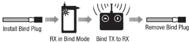
flowchart
graph LR
    A["Install Bind Plug"] --> B["RX in Bind Mode"]
    B --> C["Bind TX to RX"]
    C --> D["Remove Bind Plug"]
Binding Procedure / Switching OFF SAFE Select
IMPORTANT: The included AR636 receiver has been programmed for operation specifically for this aircraft. Refer to the receiver manual for correct setup if the receiver is replaced or is used in another aircraft.

CAUTION: When using a Futaba® transmitter with a Spektrum DSM module, you must reverse the throttle channel and rebind. Refer to your sum module manual for binding and failsafe instructions. Refer to your transmitter manual for instructions on reversing the throttle channel.
- Make sure the transmitter is powered off.
- Move the transmitter controls to neutral (flight controls: rudder, elevators and ailerons) or to low positions (throttle, throttle trim). *
- Install a bind plug in the receiver bind port.
- Place the aircraft level on its wheels, then connect the flight battery to the ESC. The ESC will produce a series of sounds. Three fl at tones followed immediately by two ascending tones confirm that the LVC is set correctly for the ESC.
The orange bind LED on the receiver will begin to flash rapidly. DO NOT remove the bind plug at this time.
- Take three steps away from the aircraft /receiver and then power ON the transmitter while holding the transmitter bind button or switch. Refer to your transmitter's manual for specific binding instructions.
IMPORTANT: Do not to point the transmitter's antenna directly at the receiver while binding.
IMPORTANT: Keep away from large metal objects while binding.
-
The receiver is bound to the transmitter when the orange bind light on the receiver stays orange. The ESC will produce a series of sounds. Three or four fl at tones followed immediately by two ascending tones. The tones indicate the number of cells in the battery and that the ESC is armed, provided the throttle stick and throttle trim are low enough to trigger arming.
-
Remove the bind plug from the bind port.
IMPORTANT: Once bound, the receiver will retain its bind settings for that transmitter until it has been intentionally changed, even when power is cycled ON and OFF. Repeat the binding process as necessary.
SAFE Select OFF Indication
Every time the receiver is powered ON the surfaces will cycle back and forth once to indicate that SAFE Select has been switched OFF.
The throttle will not arm if the transmitter's throttle control is not put at the lowest position. If problems are encountered, follow the binding instructions and refer to the transmitter troubleshooting guide for other instructions. If needed, contact the appropriate Horizon Product Support offi ce.
\* Failsafe
If the receiver loses transmitter communication, the failsafe will activate. When activated, failsafe moves the throttle channel to its preset failsafe position (low throttle) that was set during binding. All other channels move to actively level the aircraft in flight.
Battery Installation and ESC Arming
Battery Selection
We recommend the E-Flite® 2200mAh 3S 11.1V 30C LiPo battery (EFLB22003S30), for standard operation. The ESC and motor system are designed for both 3S and 4S LiPo batteries. If using a different battery, the battery should be of similar capacity, dimensions and weight of the E-Flite LiPo battery pack. Always be sure the model balances at the recommended CG with the battery chosen.
- Apply the loop side (soft side) of the hook and loop tape (A) to the bottom of your battery.
- Install a small piece of the Hook side of the hook and loop inside the fuselage where the battery will sit. Don't make this too big or the battery will be difficult to remove.
- Carefully lift the back of the canopy hatch (B) to remove.
- Install the fully charged battery in the battery compartment as shown. See the Adjusting the Center of Gravity instructions for more information.
- Make sure the flight battery is secured.
- Lower the throttle and throttle trim to the lowest settings. Power on the Transmitter, then wait 5 seconds.
- Connect the battery to the ESC (C) (the ESC is now armed).
- Keep the aircraft immobile and away from wind or the system will not initialize.

The ESC will sound a series of tones. If the ESC sounds a continuous double beep after the flight battery is connected, recharge or replace the battery.
- Reinstall the canopy hatch.
SAFE® Select Switch Designation
SAFE® Select technology can be easily assigned to any open switch (two or three position) on the transmitter. With this feature, you now have the fl exibility to switch the SAFE feature on and off while in fl ight.
IMPORTANT: Before assigning your desired switch, ensure that the travel for that channel is set at 100% in both direction.
Assigning a switch
- Bind the aircraft correctly to activate SAFE Select. This will allow the system to be assigned to a switch.
- Hold both transmitter sticks to the inside bottom corners and toggle the desired switch fi ve times (one toggle = full up and down) to assign that switch. The control surfaces of the aircraft will move, indicating the switch has been selected.
Repeat the process to assign a different switch if desired. If no switch is assigned, SAFE will be active at all times.
TIP: SAFE Select is assignable on any unused Channels 5–9


Clevis Installation and Control Centering
Clevis Adjustment
- Slide the clevis retainer off of the clevis to adjust the position on the control horn.
- Carefully spread the clevis, then insert the clevis pin into the desired hole in the control horn.
- Slide the clevis retainer back onto the clevis to secure the clevis to the control horn.
Control Surface Centering
After assembly and transmitter setup, confi rm that the control surfaces are centered. If the control surfaces are not centered, mechanically center the control surfaces by adjusting the linkages.
If adjustment is required, turn the clevis on the linkage to change the length of the linkage between the servo arm and the control horn.
After binding a transmitter to the aircraft receiver, set the trims and sub-trims to 0, then adjust the clevises to center the control surfaces.
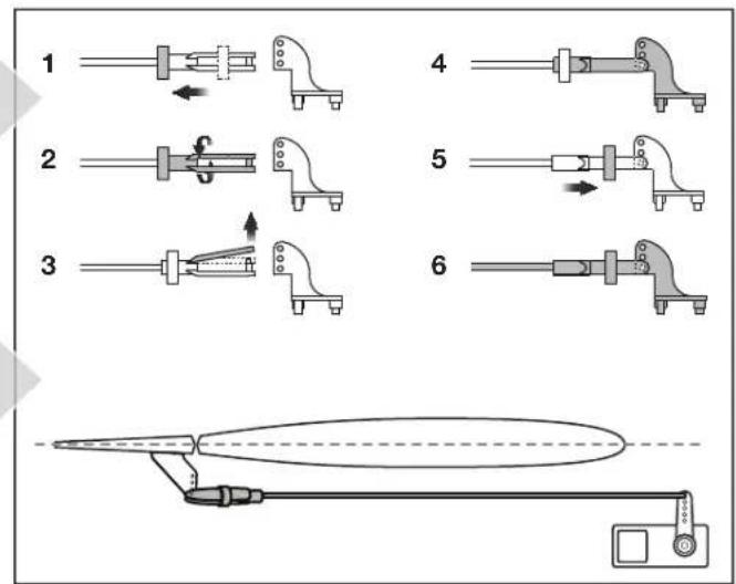
Control Horn and Servo Arm Settings
The table to the right shows the factory settings for the control horns and servo arms. Fly the aircraft at factory settings before making changes.
NOTICE: If control throws are changed from the factory settings, the gain values may need to be adjusted. Refer to your receiver manual for adjustment of gain values.
After fl ying, you may choose to adjust the linkage positions for the desired control response. See the table to the right.

Center of Gravity (CG)
The CG location is measured from the leading edge of the wing at the root. This CG location has been determined with the recommended Li-Po battery (EFLB22003S30).
The battery can be moved forward or back to adjust the CG.
NOTICE: Install the battery but do not arm the ESC while checking the CG. Personal injury may result.
88mm +/- 3mm back from leading edge of wing at the fuselage.

natural_image
Technical line drawing of a fighter jet cockpit with no visible text or symbolsControl Surface Direction
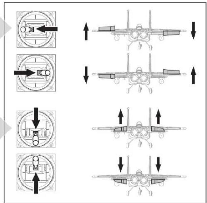
Ailerons
Switch on the transmitter and connect the battery. Use the transmitter to operate the ailerons. View the aircraft from the rear when checking the control directions.
- Move the right stick to the left. The left aileron will move up and the right aileron move down, causing the aircraft to bank left.
- Move the right stick to the right. The left aileron will move down and the right aileron move up, causing the aircraft to bank right.
Elevators
- Move the right stick toward the bottom of the transmitter. The elevators will move up, causing the aircraft to climb.
- Move the right stick toward the top of the transmitter. The elevators will move down, causing the aircraft to pitch down.
AS3X Control Direction Test (BNF Basic)
This test ensures that the AS3X® control system is functioning properly. Assemble the aircraft and bind your transmitter to the receiver before performing this test.
- Hold the aircraft and raise the throttle just above 25%, then lower the throttle to activate AS3X technology.

CAUTION: Keep all body parts, hair and loose clothing away from the aircraft, as these items could become entangled.
- Move the entire aircraft as shown and ensure the control surfaces move in the direction indicated in the graphic. If the control surfaces do not respond as shown, do not fly the aircraft. Check receiver orientation and AS3X programming.
Once the AS3X system is active, control surfaces may move rapidly. This is normal. AS3X remains active until the battery is disconnected.

flowchart
graph TD
    A["Aircraft Movement"] --> B["↑"]
    A --> C["↓"]
    D["AS3X Reaction"] --> E["↑"]
    D --> F["↓"]
    G["ELEVATORIAL"] --> H["↑"]
    G --> I["↓"]
    J["↓"] --> K["↑"]
    J --> L["↓"]
In Flight Trimming (BNF Basic)
During your fi rst fl ight, trim the aircraft for level fl ight at 3/4 throttle. Make small trim adjustments with your transmitter's trim switches to straighten the aircraft's fl ight path.
After adjusting the trim, do not touch the control sticks for 3 seconds. This allows the receiver to learn the correct settings to optimize AS3X performance.
Failure to do so could affect flight performance.

Flying Tips and Repairs
Consult local laws and ordinances before choosing a fl ying location.
Range Check your Radio System
Before you fly, range check the radio system. Refer to your specific transmitter instruction manual for range test information.
Oscillation
Once the AS3X system is active (after advancing the throttle for the first time), you will normally see the control surfaces react to aircraft movement. In some flight conditions you may see oscillation (the aircraft rocks back and forth on one axis due to overcontrol). If oscillation occurs, refer to the Troubleshooting Guide for more information.
Takeoff
Place the aircraft facing into the wind. Set your transmitter in low rate. Gradually increase the throttle to 34 and steer with the rudder. As the plane reaches flying speed, pull back gently on the elevator. When airborne, climb to a comfortable altitude.
Flying
For your fi rst fl ights with the recommended battery pack (EFLB22003S30), set your transmitter timer or a stopwatch to 3 minutes. After three minutes, land the aircraft. Adjust your timer for longer or shorter fl ights once you have fl own the model. If at any time the motor power reduces, land the aircraft immediately to recharge the fl ight battery. See the Low Voltage Cutoff (LVC) section for more details on maximizing battery health and run time.
Landing
Land the aircraft into the wind. Use a small amount of throttle for the entire descent. Lower the throttle to 14 .
Keep the throttle on until the aircraft is ready to fl are. During fl are, keep the wings level and the aircraft pointed into the wind. Gently lower the throttle while pulling back on the elevator to bring the aircraft down on its wheels.
Once on the ground, avoid sharp turns until the plane has slowed enough to prevent scraping the wingtips.
NOTICE: If a crash is imminent, reduce the throttle. Failure to do so could result in extra damage to the airframe, as well as damage to the ESC and motor.
NOTICE: After any impact, always ensure the receiver is secure in the fuselage. If you replace the receiver, install the new receiver in the same orientation as the original receiver or damage may result.
NOTICE: Crash damage is not covered under warranty.
NOTICE: When you are fi nished fl ying, never leave the aircraft in direct sunlight or in a hot, enclosed area such as a car. Doing so can damage the aircraft.
Low Voltage Cutoff (LVC)
When a Li-Po battery is discharged below 3V per cell, it will not hold a charge. The ESC protects the fl light battery from over-discharge using Low Voltage Cutoff (LVC). Before the battery charge decreases too much, LVC reduces power supplied to the motor showing that some battery power is low but there is still enough reserved for fl light control and safe landing.
Disconnect and remove the Li-Po battery from the aircraft after use to prevent trickle discharge. Charge your Li-Po battery to about half capacity before long storage. During storage, make sure the battery charge never falls below 3V per cell. LVC does not prevent the battery from over-discharge during storage.
NOTICE: Repeated fl ying to LVC will damage the battery.
TIP: Monitor your aircraft battery's voltage before and after fl ying by using a Li-Po Cell Voltage Checker (EFLA111, sold separately).
Repairs
Thanks to the EPO foam material in this aircraft, repairs to the foam can be made using virtually any adhesive (hot glue, regular CA, epoxy, etc). When parts are not repairable, see the Replacement Parts List for ordering by item number. For a listing of all replacement and optional parts, refer to the list at the end of this manual.
NOTICE: Use of CA accelerant on your aircraft can damage paint. DO NOT handle the aircraft until accelerant fully dries.
Post Flight
- Disconnect the flight battery from the ESC (Required for Safety and battery life).
- Power OFF the transmitter.
- Remove the flight battery from the aircraft.
-
Recharge the flight battery.
-
Repair or replace all damaged parts.
- Store the flight battery apart from the aircraft and monitor the battery charge.
- Make note of the flight conditions and flight plan results, planning for future flights.
Power Components Service

CAUTION: Always disconnect the flight battery before performing motor service.
Disassembly
- Carefully remove the lower cover to gain access to the ESC. It is held on with fl exible glue that can be gently pulled away.
- Disconnect the motor connectors from the ESC.
- To access the motor/fan unit, remove the two screws (one on each side).
-
Disassemble the motor/fan as needed.
-
Assembly in reverse order.
- Make sure the spinner is fully seated on the fan blade for safe operation.
- Make sure you match the colors on the ESC wires with the colors on the motor.

natural_image
Technical illustration of a mechanical assembly showing a fan blade and internal components (no text or symbols)Troubleshooting Guide AS3X
Problem Possible Cause Solution
| Oscillation | Motor vibration Replace parts or correctly align all parts and tighten fasteners as needed | |
| Loose receiver Align and secure receiver in fuselage | ||
| Loose aircraft controls | Tighten or otherwise secure parts (servo, arm, linkage, horn and control surface) | |
| Worn parts Replace worn parts (especially propeller, spinner or servo) | ||
| Irregular servo movement Replace servo | ||
| Inconsistent fl ight performance | Trim is not at neutral If you adjust trim more than 8 clicks, adjust the clevis to remove trim | |
| Sub-Trim is not at neutral No Sub-Trim is allowed. Adjust the servo linkage | ||
| Aircraft was not kept immobile for 5 seconds after battery connection | With the throttle stick in lowest position. Disconnect battery, then reconnect battery and keep the aircraft still for 5 seconds | |
| Incorrect response to the AS3X Control Direction Test | Incorrect direction settings in the receiver, which can cause a crash | DO NOT fl y. Correct the direction settings using a AS3X programmer |
Troubleshooting Guide
| Problem Possible Cause Solution | ||
| Aircraft will not respond to throttle but responds to other controls | Throttle not at idle and/or throttle trim too high | Reset controls with throttle stick and throttle trim at lowest setting |
| Throttle servo travel is lower than 100% Make sure throttle | Servo travel is 100% or greater | |
| Throttle channel is reversed Reverse throttle channel on transmitter | ||
| Motor disconnected from ESC Make sure motor is connected to the ESC | ||
| Extra noise or extra vibration during throttle operation | Damaged rotor, collet or motor Replace damaged parts | |
| Rotor is out of balance Balance or replace rotor | ||
| Rotor nut is too loose Tighten the rotor nut | ||
| Reduced flight time or aircraft underpowered | Flight battery charge is low Completely recharge flight battery | |
| Flight battery damaged | Replace flight battery and follow flight battery instructions | |
| Flight conditions may be too cold Make sure battery is warm before use | ||
| Battery capacity too low for flight conditions Replace battery or use a larger capacity battery | ||
| Aircraft will not connect (during binding) to transmitter | Transmitter too near aircraft during binding process | Move powered transmitter a few feet from aircraft, disconnect and reconnect flight battery to aircraft |
| Aircraft or transmitter is too close to large metal object, wireless source or another transmitter | Move aircraft and transmitter to another location and attempt binding again | |
| The bind plug is not installed correctly in the bind port | Install bind plug in bind port and bind the aircraft to the transmitter | |
| Flight battery/transmitter battery charge is too low Replace/recharge batteries | ||
| Bind switch or button not held long enough during bind process | Power off transmitter and repeat bind process. Hold transmitter bind button or switch until receiver is bound | |
| Aircraft will not connect (after binding) to transmitter | Transmitter too near aircraft during connecting process | Move powered transmitter a few feet from aircraft, disconnect and reconnect flight battery to aircraft |
| Aircraft or transmitter is too close to large metal object, wireless source or another transmitter | Move aircraft and transmitter to another location and attempt connecting again | |
| Bind plug left installed in bind port | Rebind transmitter to the aircraft and remove the bind plug before cycling power | |
| Aircraft bound to different model memory (ModelMatchTM radios only) | Select correct model memory on transmitter | |
| Flight battery/Transmitter battery charge is too low | Replace/recharge batteries | |
| Transmitter may have been bound to a different aircraft using different DSM protocol | Bind aircraft to transmitter | |
| Control surface does not move | Control surface, control horn, linkage or servo damage | Replace or repair damaged parts and adjust controls |
| Wire damaged or connections loose | Do a check of wires and connections, connect or replace as needed | |
| Transmitter is not bound correctly or the incorrect airplanes was selected | Re-bind or select correct airplanes in transmitter | |
| Flight battery charge is low Fully recharge flight battery | ||
| BEC (Battery Elimination Circuit) of the ESC is damaged | Replace ESC | |
| Controls reversed | Transmitter settings are reversed | Perform the Control Direction Test and adjust the controls on the transmitter appropriately |
| Motor power pulses then motor loses power | ESC uses default soft Low Voltage Cutoff (LVC) | Recharge flight battery or replace battery that is no longer performing |
| Weather conditions might be too cold | Postpone flight until weather is warmer | |
| Battery is old, worn out, or damaged | Replace battery | |
| Battery C rating might be too small | Use recommended battery | |
A. GENERAL
A model aircraft is a non-human-carrying aircraft capable of sustained flight in the atmosphere. It may not exceed limitations of this code and is intended exclusively for sport, recreation, education and/or competition. All model flights must be conducted in accordance with this safety code and any additional rules specific to the flying site.
- Model aircraft will not be flown:
(a) In a careless or reckless manner.
(b) At a location where model aircraft activities are prohibited.
- Model aircraft pilots will
(a) Yield the right of way to all man carrying aircraft
(b) See and avoid all aircraft and a spotter must be used when appropriate. (AMA Document #540-D.)
(c) Not fly higher than approximately 400 feet above ground level within three (3) miles of an airport, without notifying the airport operator.
(d) Not interfere with operations and traffic patterns at any airport, heliport or seaplane base except where there is a mixed use agreement.
(e) Not exceed a takeoff weight, including fuel, of 55 pounds unless in compliance with the AMA Large Model Aircraft program. (AMA Document 520-A.)
(f) Ensure the aircraft is identified with the name and address or AMA number of the owner on the inside or affixed to the outside of the model aircraft. (This does not apply to model aircraft fl own indoors).
(g) Not operate aircraft with metal-blade propellers or with gaseous boosts except for helicopters operated under the provisions of AMA Document #555.
(h) Not operate model aircraft while under the influence of alcohol or while using any drug which could adversely affect the pilot's ability to safely control the model.
(i) Not operate model aircraft carrying pyrotechnic devices which explode or burn, or any device which propels a projectile or drops any object that creates a hazard to persons or property.
Exceptions:
- Free Flight fuses or devices that burn producing smoke and are securely attached to the model aircraft during flight.
- Rocket motors (using solid propellant) up to a G-series size may be used provided they remain attached to the model during flight. Model rockets may be flown in accordance with the National Model Rocketry Safety Code but may not be launched from model aircraft.
- Officially designated AMA Air Show Teams (AST) are authorized touse devices and practices as defined within the Team AMA Program Document (AMA Document #718).
(j) Not operate a turbine-powered aircraft, unless in compliance with the AMA turbine regulations. (AMA Document #510-A).
- Model aircraft will not be flown in AMA sanctioned events, air shows or model demonstrations unless:
(a) The aircraft, control system and pilot skills have successfully demonstrated all maneuvers intended or anticipated prior to the specific event.
(b) An inexperienced pilot is assisted by an experienced pilot.
- When and where required by rule, helmets must be properly worn and fastened. They must be OSHA, DOT, ANSI, SNELL or NOCSAE approved or comply with comparable standards.
B. RADIO CONTROL
- All pilots shall avoid flying directly over unprotected people, vessels, vehicles or structures and shall avoid endangerment of life and property of others.
- A successful radio equipment ground-range check in accordance with manufacturer's recommendations will be completed before the first flight of a new or repaired model aircraft.
- At all fl ying sites a safety line(s) must be established in front of which all fl ying takes place (AMA Document #706.)
(a) Only personnel associated with flying the model aircraft are allowed at or in front of the safety line.
(b) At air shows or demonstrations, a straight safety line must be established.
(c) An area away from the safety line must be maintained for spectators.
(d) Intentional fl ying behind the safety line is prohibited.
- RC model aircraft must use the radio-control frequencies currently allowed by the Federal Communications Commission (FCC). Only individuals properly licensed by the FCC are authorized to operate equipment on Amateur Band frequencies.
- RC model aircraft will not operate within three (3) miles of any pre-existing fl ying site without a frequency-management agreement (AMA Documents #922 and #923.)
- With the exception of events flown under official AMA Competition Regulations, excluding takeoff and landing, no powered model may be flown outdoors closer than 25 feet to any individual, except for the pilot and the pilot's helper(s) located at the flight line.
- Under no circumstances may a pilot or other person touch a model aircraft in flight while it is still under power, except to divert it from striking an individual.
- RC night fl ying requires a lighting system providing the pilot with a clear view of the model's attitude and orientation at all times. Hand-held illum-nation systems are inadequate for night fl ying operations.
- The pilot of a RC model aircraft shall:
(a) Maintain control during the entire flight, maintaining visual contact without enhancement other than by corrective lenses prescribed for the pilot.
(b) Fly using the assistance of a camera or First-Person View (FPV) only in accordance with the procedures outlined in AMA Document #550.
(C) Fly using the assistance of autopilot or stabilization system only in accordance with the procedures outlined in AMA Document #560.
Please see your local or regional modeling association's guidelines for proper, safe operation of your model aircraft.
Limited Warranty
What this Warranty Covers
Horizon Hobby, LLC, (Horizon) warrants to the original purchaser that the product purchased (the "Product") will be free from defects in materials and workmanship at the date of purchase.
What is Not Covered
This warranty is not transferable and does not cover (i) cosmetic damage, (ii) damage due to acts of God, accident, misuse, abuse, negligence, commercial use, or due to improper use, installation, operation or maintenance, (iii) modification of or to any part of the Product, (iv) attempted service by anyone other than a Horizon Hobby authorized service center, (v) Product not purchased from an authorized Horizon dealer, or (vi) Product not compliant with applicable technical regulations, or (vii) use that violates any applicable laws, rules, or regulations.
OTHER THAN THE EXPRESS WARRANTY ABOVE, HORIZON MAKES NO OTHER WARRANTY OR REPRESENTATION, AND HEREBY DISCLAIMS ANY AND ALL IMPLIED WARRANTIES, INCLUDING, WITHOUT LIMITATION, THE IMPLIED WARRANTIES OF NON-INFRINGEMENT, MERCHANTABILITY AND FITNESS FOR A PARTICULAR PURPOSE. THE PURCHASER ACKNOWLEDGES THAT THEY ALONE HAVE DETERMINED THAT THE PRODUCT WILL SUITABLY MEET THE REQUIREMENTS OF THE PURCHASER'S INTENDED USE.
Purchaser's Remedy
Horizon's sole obligation and purchaser's sole and exclusive remedy shall be that Horizon will, at its option, either (i) service, or (ii) replace, any Product determined by Horizon to be defective. Horizon reserves the right to inspect any and all Product(s) involved in a warranty claim. Service or replacement decisions are at the sole discretion of Horizon. Proof of purchase is required for all warranty claims. SERVICE OR REPLACEMENT AS PROVIDED UNDER THIS WARRANTY IS THE PURCHASER'S SOLE AND EXCLUSIVE REMEDY.
Limitation of Liability
HORIZON SHALL NOT BE LIABLE FOR SPECIAL, INDIRECT, INCIDENTAL OR CONSEQUENTIAL DAMAGES, LOSS OF PROFITS OR PRODUCTION OR COMMERCIAL LOSS IN ANY WAY, REGARDLESS OF WHETHER SUCH CLAIM IS BASED IN CONTRACT, WARRANTY, TORT, NEGLIGENCE, STRICT LIABILITY OR ANY OTHER THEORY OF LIABILITY, EVEN IF HORIZON HAS BEEN ADVISED OF THE POSSIBILITY OF SUCH DAMAGES. Further, in no event shall the liability of Horizon exceed the individual price of the Product on which liability is asserted. As Horizon has no control over use, setup, fi nal assembly, modifi cation or misuse, no liability shall be assumed nor accepted for any resulting damage or injury. By the act of use, setup or assembly, the user accepts all resulting liability. If you as the purchaser or user are not prepared to accept the liability associated with the use of the Product, purchaser is advised to return the Product immediately in new and unused condition to the place of purchase.
Law
These terms are governed by Illinois law (without regard to conflict of law principals). This warranty gives you specific legal rights, and you may also have other rights which vary from state to state. Horizon reserves the right to change or modify this warranty at any time without notice.
WARRANTY SERVICES
Questions, Assistance, and Services
Your local hobby store and/or place of purchase cannot provide warranty support or service. Once assembly, setup or use of the Product has been started, you must contact your local distributor or Horizon directly. This will enable Horizon to better answer your questions and service you in the event that you may need any assistance. For questions or assistance, please visit our website at www.horizonhobby.com, submit a Product Support Inquiry, or call the toll free telephone number referenced in the Warranty and Service Contact Information section to speak with a Product Support representative.
Inspection or Services
If this Product needs to be inspected or serviced and is compliant in the country you live and use the Product in, please use the Horizon Online Service Request submission process found on our website or call Horizon to obtain a Return Merchandise Authorization (RMA) number. Pack the Product securely using a shipping carton. Please note that original boxes may be included, but are not designed to withstand the rigors of shipping without additional protection. Ship via a carrier that provides tracking and insurance for lost or damaged parcels, as Horizon is not responsible for merchandise until it arrives and is accepted at our facility. An Online Service Request is available at http://www.horizonhobby.com/content/_service-center_render-service-center. If you do not have internet access, please contact Horizon Product Support to obtain a RMA number along with instructions for submitting your product for service. When calling Horizon, you will be asked to provide your complete name, street address, email address and phone number where you can be reached during business hours. When sending product into Horizon, please include your RMA number, a list of the included items, and a brief summary of the problem. A copy of your original sales receipt must be included for warranty consideration. Be sure your name, address, and RMA number are clearly written on the outside of the shipping carton.
NOTICE: Do not ship LiPo batteries to Horizon. If you have any issue with a LiPo battery, please contact the appropriate Horizon Product Support offi ce.
Warranty Requirements
For Warranty consideration, you must include your original sales receipt verifying the proof-of-purchase date. Provided warranty conditions have been met, your Product will be serviced or replaced free of charge. Service or replacement decisions are at the sole discretion of Horizon.
Non-Warranty Service
Should your service not be covered by warranty, service will be completed and payment will be required without notification or estimate of the expense unless the expense exceeds 50% of the retail purchase cost. By submitting the item for service you are agreeing to payment of the service without notification. Service estimates are available upon request. You must include this request with your item submitted for service. Non-warranty service estimates will be billed a minimum of 12 hour of labor. In addition you will be billed for return freight. Horizon accepts money orders and cashier's checks, as well as Visa, MasterCard, American Express, and Discover cards. By submitting any item to Horizon for service, you are agreeing to Horizon's Terms and Conditions found on our website http://www.horizonhobby.com/content/_service-center_render-service-center.
ATTENTION: Horizon service is limited to Product compliant in the country of use and ownership. If received, a non-compliant Product will not be serviced. Further, the sender will be responsible for arranging return shipment of the un-serviced Product, through a carrier of the sender's choice and at the sender's expense. Horizon will hold non-compliant Product for a period of 60 days from notification, after which it will be discarded.
10/15
Contact Information
Country of Purchase Horizon Hobby Contact Information Address
| United States of America | Horizon Service Center (Repairs and Repair Requests) | servicecenter.horizonhobby.com/RequestForm/ | 2904 Research Rd Champaign, Illinois, 61822 USA |
| Horizon Product Support (Product Technical Assistance) | productsupport@horizonhobby.com | ||
| 877-504-0233 | |||
| Sales | websales@horizonhobby.com | ||
| 800-338-4639 | |||
| European Union | Horizon Technischer Service service@horizonhobby.eu | Hanskampring 9 D 22885 Barsbüttel, Germany | |
| Sales: Horizon Hobby GmbH +49 (0) 41 | 21 2655 100 | ||
FCC Information
FCC ID: BRWDASRX15
This device complies with part 15 of the FCC rules. Operation is subject to the following two conditions: (1) This device may not cause harmful interference, and (2) this device must accept any interference received, including interference that may cause undesired operation.
CAUTION: Changes or modifications not expressly approved by the party responsible for compliance could void the user's authority to operate the equipment.
This product contains a radio transmitter with wireless technology which has been tested and found to be compliant with the applicable regulations governing a radio transmitter in the 2.400GHz to 2.4835GHz frequency range.
Supplier's Declaration of Conformity
F-15 Eagle 64mm EDF BNF Basic with AS3X and SAFE Select EFL9750
This device complies with part 15 of the FCC Rules. Operation is subject to the following two conditions: (1) This device may not cause harmful interference, and (2) this device must accept any interference received, including interference that may cause undesired operation.
CAUTION: changes or modifications not expressly approved by the party responsible for compliance could void the user's authority to operate the equipment.
NOTE: This equipment has been tested and found to comply with the limits for a Class B digital device, pursuant to part 15 of the FCC Rules. These limits are designed to provide reasonable protection against harmful interference in a residential installation. This equipment generates, uses and can radiate radio frequency energy and, if not installed and used in accordance with the instructions, may cause harmful interference to radio communications. However, there is no guarantee that interference will not occur in a particular installation. If this equipment does cause harmful interference to radio or television reception, which can be determined by turning the equipment off and on, the user is encouraged to try to correct the interference by one or more of the following measures:
- Reorient or relocate the receiving antenna.
- Increase the separation between the equipment and receiver.
- Connect the equipment into an outlet on a circuit different from that to which the receiver is connected.
- Consult the dealer or an experienced radio/TV technician for help.
Horizon Hobby, LLC
4105 Fieldstone Rd.,
Champaign, IL 61822
Email: compliance@horizonhobby.com
Web: HorizonHobby.com
IC Information
IC: 6157A-AMRX15
CAN ICES-3 (B)/NMB-3(B)
This device complies with Industry Canada licence-exempt RSS standard(s). Operation is subject to the following two conditions:
(1) this device may not cause interference, (2) this device must accept any interference, including interference that may cause undesired operation of the device.
Compliance Information for the European Union

EU Compliance Statement:
EFL9750 F-15 Eagle 64mm EDF PNP; Horizon Hobby, LLC hereby declares that this product is in compliance with the essential requirements and other relevant provisions of the EMC Directive.
EFL9775 F-15 Eagle 64mm EDF BNF BASIC; Horizon Hobby, LLC hereby declares that this product is in compliance with the essential requirements and other relevant provisions of the RED and EMC Directives.
A copy of the EU Declaration of Conformity is available online at: http://www.horizonhobby.com/content/support-render-compliance.
Instructions for disposal of WEEE by users in the European Union

This product must not be disposed of with other waste. Instead, it is the user's responsibility to dispose of their waste equipment by handing it over to a designated collections point for the recycling of waste electrical and electronic equipment. The separate collection and recycling of your waste equipment at the time of disposal will help to conserve natural resources and make sure that it is recycled in a manner that protects human health and the environment. For more information about where you can drop off your waste equipment for recycling, please contact your local city office, your household waste disposal service or where you purchased the product.

E328
Replacement Parts • Ersatzteile • Pièces de rechange • Pezzi di ricambio
| Part # I Nummer Numéro | Codice | Description Beschreibung Description Descrizione | |||
| EFL9776 Fuselage: F-15 64mm EDF Rumpf: F-15 64mm EDF | Fuselage : Soufflante électrique F-15 64 mm | Fusoliera: F-15 64 mm EDF | ||
| EFL9777 | Wing Set: F-15 64mm EDF | Flügelsatz: F-15 64mm EDF | Ensemble d'aile : Soufflante électrique F-15 64 mm | Set ali: F-15 64 mm EDF |
| EFL9778 | Stabilizer Set: F-15 64mm EDF | Stabilisatorsatz: F-15 64mm EDF | Ensemble de stabilisateur : Soufflante électrique F-15 64 mm | Set stabilizzatori: F-15 64 mm EDF |
| EFL9779 Vertical Fins: F-15 64mm EDF | Stabilisierungsflossen: F-15 64mm EDF | Dérives verticales : Soufflante électrique F-15 64 mm | Derive verticali: F-15 64 mm EDF | |
| EFL9780 Nose Cone: F-15 64mm EDF Bugspitze: F-15 64mm EDF | Cône de nez : Soufflante électrique F-15 64 mm | Musc: F-15 64 mm EDF | ||
| EFL9781 Canopy/Hatch: F-15 64mm EDF | Kanzelabdeckung: F-15 64mm EDF | Verrière/Trappe : Soufflante électrique F-15 64 mm | Tettuccio: F-15 64 mm EDF | |
| EFL9782 | Dummy Ordnance: F-15 64mm EDF | Geschoss-Attrappe: F-15 64mm EDF | Matériel de guerre factice : Soufflante électrique F-15 64 mm | Munizionamento simulato: F-15 64 mm EDF |
| EFL9783 Linkage Rod Set: F-15 64mm EDF Gestängesatz: F-15 64mm EDF | Ensemble de tige de liaison : Soufflante électrique F-15 64 mm | Set asta di collegamento: F-15 64 mm EDF | ||
| EFL9784 | Wing Tube: F-15 64mm EDF Steckungsrohr: F-15 64mm EDF | Tube d'aile : Soufflante électrique F-15 64 mm | Tubo ala: F-15 64 mm EDF | |
| EFL9785 | Landing Gear Set: F-15 64mm EDF | Fahrwerksatz: F-15 64mm EDF | Ensemble de train d'atterrissage : Soufflante électrique F-15 64 mm | Set carrello d'atterraggio: F-15 64 mm EDF |
| EFL9786 Decal Set: F-15 64mm EDF Decal-Satz: F-15 64mm EDF | Lot d'autocollants : Soufflante électrique F-15 64 mm | Set decalcomanie: F-15 64 mm EDF | ||
| EFL9787 | Motor: F-15 64mm EDF 2840-3150 Kv | Motor: F-15 64mm EDF 2840-3150Kv | Moteur : Soufflante électrique F-15 64 mm 2 840-3 150 Kv | Motore: F-15 64 mm EDF 2840-3150 Kv |
| EFL9788 | Servo: 9g Positive | Servo: 9 g Positiv | Servo : 9g Positif | Servocomando: 9 g positivo |
| EFL9789 | Servo: 9g Reverse | Servo: 9 g Umkehr | Servo : 9g Inverse | Servocomando: 9 g negativo |
| EFL9790 | Ducted Fan: 64mm EDF Unit | Impeller: 64mm EDF Einheit | Soufflante : Soufflante électrique 64 mm | Ventola intubata: unità 64 mm EDF |
| EFL9791 ESC: 64mm EDF 40A | Geschwindigkeitsregler: 64mm EDF 40A | Variateur ESC : Soufflante électrique 64 mm 40 A | ESC: 64 mm EDF 40 A | |
| EFL9792 | Servo: 9g 54 degree Steering | Servo: 9 g 54-Grad-Lenkung | Servo : Direction 9g 54 degrés | Servocomando: 9 g 54° direzione |
| EFL9793 Pilot: F-15 Eagle 64mm EDF Pilot: F-15 Eagle 64mm EDF | Pilote : Soufflante électrique F-15 Eagle 64 mm | Pilota: F-15 Eagle 64 mm EDF | ||
| SPMAR636 | AR636 6-Ch AS3X Sport Receiver | AR636 AS3X-Sportempfänger mit 6 Kanälen | Récepteur AR636 AS3X Sport 6 canaux | Ricevitore AR636 AS3X Sport a 6 canali |
Optional Parts • Optionale Bauteile • Pièces optionnelles • Pezzi opzionali
| Part # I Nummer Numéro I Codice | Description Beschreibung Description Descrizione | |||
| SPMR6650 DX6e 6 | CH Transmitter Only Nur DX6e 6CH | Sender | Émetteur DX6e uniquement 6 canaux | Solo trasmittente DX6e 6CH |
| SPMX22003S30 | 2200 mAh 3S 11.1V Smart 30C; IC3 | 2200 mAh 3S 11,1 V Smart 30C; IC3 | 2 200 mAh 3S 11,1 V Smart 30 C ; IC3 | 2200 mAh 3S 11,1 V Smart 30C; IC3 |
| SPMX22004S30 | 2200 mAh 4S 14.8V Smart 30C; IC3 | 2200 mAh 3S 14,8 V Smart 30C; IC3 | 2 200 mAh 4S 14,8 V Smart 30 C ; IC3 | 2200 mAh 4S 14,8 V Smart 30C; IC3 |
| SPMXC1000 | Smart S1200 DC Charger, 1x200W | Smart S1200 Gleichstrom-Ladegerät, 1x200 W | Chargeur CC Smart S1200, 1x200 W | Caricabatterie Smart S1200 DC, 1x200 W |
| DYNC2030 Prophet | Sport Mini 50W Charger | Prophet Sport Mini 50 W Ladegerät | Chargeur 50 W Prophet Sport Mini | Caricabatterie Prophet Sport Mini 50 W |
| EFLB22003S30 | 2200mAh 3S 11.1V 30C LiPo, 13AWG EC3 | 2200 mAh 3S 11,1 V 30C LiPo, 13AWG EC3 | 2 200 mAh 3S 11,1 V 30 C Li-Po, 13AWG EC3 | Batteria LiPo 2200 mAh 3S 11,1 V 30C, 13AWG EC3 |
| EFLB22004S30 | 2200 mAh 4S 14.8V 30C LiPo, 13AWG EC3 | 2200 mAh 4S 14,8 V 30C LiPo, 13AWG EC3 | 2 200 mAh 4S 14,8 V 30 C Li-Po, 13AWG EC3 | Batteria LiPo 2200 mAh 4S 14,8 V 30C, 13AWG EC3 |
| SPMR12000 iX12 | 2 Channel Transmitter Only Nur iX1 | 2-Sender mit 12 Kanälen | Émetteur iX12 12 canaux uniquement | Solo trasmittente iX12 12 canali |
| SPMR8100 DX8e 8 | CH Transmitter Only Nur DX8e-Sender mit 8 Kanälen | Émetteur DX8e 8 canaux uniquement | Solo trasmittente DX8e 8 canali | |
E- flite®
ADVANCING ELECTRIC FLIGHT
© 2018 Horizon Hobby, LLC.
E-flite, DSM, DSM2, DSMX, Bind-N-Fly, BNF, the BNF logo, Plug-N-Play, AS3X, SAFE, the SAFE logo, ModelMatch, Prophet, EC3, and the Horizon Hobby logo are trademarks or registered trademarks of Horizon Hobby, LLC.
The Spektrum trademark is used with permission of Bachmann Industries, Inc.
Futaba is a registered trademark of Futaba Denshi Kogyo Kabushiki Kaisha Corporation of Japan.
All other trademarks, service marks and logos are property of their respective owners.
US 8,672,726. US 9,056,667. Other patents pending.
http://www.e-fl iterc.com/



- Meaning of Special Language
- Safety Precautions and Warnings
- Box Contents
- Components
- Table of Contents
- SAFE® Select Technology (BNF Basic)
- Preflight
- Transmitter Setup (BNF Basic)
- Dual Rates
- Expo
- Model Assembly
- Landing Gear Installation
- Wing Installation
- Model Assembly Continued
- Horizontal Stabilizer Installation
- Vertical Stabilizer Installation
- Missile Installation
- Nose Cone Installation
- PNP Receiver Selection and Installation
- Installation (AR636 shown)
- Transmitter and Receiver Binding / Enabling and Disabling SAFE Select (BNF Basic)
- Binding Procedure / Switching ON SAFE Select
- SAFE Select ON Indication
- Binding Procedure / Switching OFF SAFE Select
- SAFE Select OFF Indication
- \* Failsafe
- Battery Installation and ESC Arming
- Battery Selection
- SAFE® Select Switch Designation
- Assigning a switch
- Clevis Installation and Control Centering
- Clevis Adjustment
- Control Surface Centering
- Control Horn and Servo Arm Settings
- Center of Gravity (CG)
- Control Surface Direction
- Ailerons
- Elevators
- AS3X Control Direction Test (BNF Basic)
- In Flight Trimming (BNF Basic)
- Flying Tips and Repairs
- Range Check your Radio System
- Oscillation
- Takeoff
- Flying
- Landing
- Low Voltage Cutoff (LVC)
- Repairs
- Post Flight
- Power Components Service
- Disassembly
- Troubleshooting Guide AS3X
- GENERAL
- Exceptions:
- RADIO CONTROL
- Limited Warranty
- What this Warranty Covers
- What is Not Covered
- Purchaser's Remedy
- Limitation of Liability
- Law
- WARRANTY SERVICES
- Questions, Assistance, and Services
- Inspection or Services
- Warranty Requirements
- Non-Warranty Service
- Contact Information
- FCC Information
- FCC ID: BRWDASRX15
- Supplier's Declaration of Conformity
- IC Information
- Compliance Information for the European Union
- E- flite®
- ADVANCING ELECTRIC FLIGHT
Brand : E-flite
Model : F-15 Eagle
Category : Remote control toy