
EFLU6800 - Remote control toy E-flite - Free user manual and instructions
Find the device manual for free EFLU6800 E-flite in PDF.

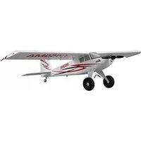
| Product Type | RC Airplane |
| Brand | E-flite |
| Model | EFLU6800 |
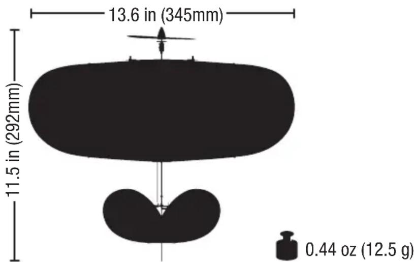
| Wingspan | 800 mm (31.5 in) |
| Length | 700 mm (27.6 in) |
| Weight (without battery) | 180 g (6.3 oz) |
| Battery | 2S 7.4V 280-450 mAh LiPo |
| Motor | Brushless outrunner |
| Controls | 4 channels (throttle, aileron, elevator, rudder) |
| Transmitter Compatibility | DSMX/DSM2, BNF Basic (requires own transmitter) |
| Flight Time | Approximately 6-8 minutes |
| Range | Up to 300 m (1000 ft) |
| Materials | E-flite foam (EPO), carbon fiber reinforcement |
| Assembly Required | Minimal (install landing gear, battery, attach wings) |
| Special Features | SAFE Select technology with optional AS3X stability |
| Recommended Age | 14+ years |
| Battery Charger | Requires 2S LiPo balance charger (not included) |
| Maintenance | Clean with damp cloth, avoid moisture in electronics |
| Repair Parts | Available from Horizon Hobby or authorized dealers |
Frequently Asked Questions - EFLU6800 E-flite
User questions about EFLU6800 E-flite
0 question about this device. Answer the ones you know or ask your own.
Ask a new question about this device
Download the instructions for your Remote control toy in PDF format for free! Find your manual EFLU6800 - E-flite and take your electronic device back in hand. On this page are published all the documents necessary for the use of your device. EFLU6800 by E-flite.
USER MANUAL EFLU6800 E-flite
Instruction Manual
Bedienungsanleitung
All instructions, warranties and other collateral documents are subject to change at the sole discretion of Horizon Hobby, LLC. For up-to-date product literature, visit www.horizonhobby.com and click on the support tab for this product.
Meaning of Special Language:
The following terms are used throughout the product literature to indicate various levels of potential harm when operating this product:
WARNING: Procedures, which if not properly followed, create the probability of property damage, collateral damage and serious injury OR create a high probability of superficial injury.
CAUTION: Procedures, which if not properly followed, create the probability of physical property damage AND a possibility of serious injury.
NOTICE: Procedures, which if not properly followed, create a possibility of physical property damage AND little or no possibility of injury.

WARNING: Read the ENTIRE instruction manual to become familiar with the features of the product before operating. Failure to operate the product correctly can result in damage to the product, nal property and cause serious injury.
This is a sophisticated hobby product. It must be operated with caution and common sense and requires some basic mechanical ability. Failure to operate this Product in a safe and responsible manner could result in injury or damage to the product or other property. This product is not intended for use by children without direct adult supervision. Do not attempt disassembly, use with incompatible components or augment product in any way without the approval of Horizon Hobby, LLC. This manual contains instructions for safety, operation and maintenance. It is essential to read and follow all the instructions and warnings in the manual prior to assembly, setup or use in order to operate correctly and avoid damage or serious injury.
Age Recommendation: Not for children under 14 years. This is not a toy.
Welcome to an exciting new world of fl ying possibilities. Bedrooms, conference rooms, garages, basements, break rooms, offi ces—all can be transformed into aerial RC playgrounds with the UMX™ Vapor® Lite HP. Its small size, negligible mass and proportional 3-channel control will let you confi dently fl y almost anywhere indoors without worrying about damage to it or the furniture.
Before you start exploring your new found fl ying opportunities, however, you must take some time to read this manual. It contains important information about some of the aircraft's wind limitations, DSM2®/DSMX® technology, battery charging and much more. You'll also fi nd a handy troubleshooting guide. It's all here to make sure your fi rst fl ight, and every one after, is the best it can be.
Box Contents
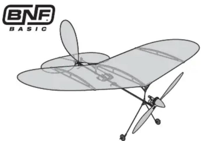
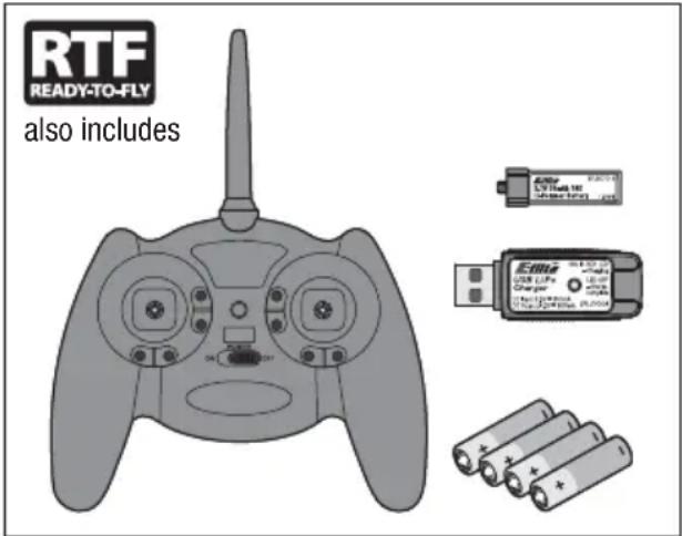
Table of Contents
Charging Warnings....4
Charging the Battery ....5
Installing Transmitter Batteries ....6
Transmitter and Receiver Binding 6
Installing the Flight Battery and Arming the ESC ...7
Preflight Checklist 7
Digital Trims 8
Dual Rate Function 8
Transmitter Control 8
Control Direction Test 9
Reverse Controls ....10
Control Centering 10
Settings for Control Horns 10
Control Rates ......11
Adjusting Center of Gravity (CG) 11
Motor Service 12
Flying Tips and Repairs ....13
Additional Safety Precautions and Warnings .....13
Troubleshooting Guide ....14
Post Flight Checklist ....15
Limited Warranty ....16
Warranty and Service Information ....17
FCC Information 18
IC Information 18
Compliance Information for the European Union ....18
Replacement Parts 70
Optional Parts and Accessories ....71
Specifications


| Motor: Vapor, Ember 2 (PKZ3316) Installed Installed | |||
| Super Lite DSMX® RX/ESC/Servos (PKZU1252) Installed Installed | |||
| Battery: 70mAh 1S 3.7V 14C Li-Po (EFLB0701S) | Included | Needed to Complete | |
| Charger: E-Flite® 1S 3.7V Li-Po USB (EFLC1008) | Included | Needed to Complete | |
| E-fl ite® MLP4 DSM® Transmitter (EFLR1064) | Included | Needed to Complete |
To register your product online, go to www.e-fl iterc.com
Charging Warnings
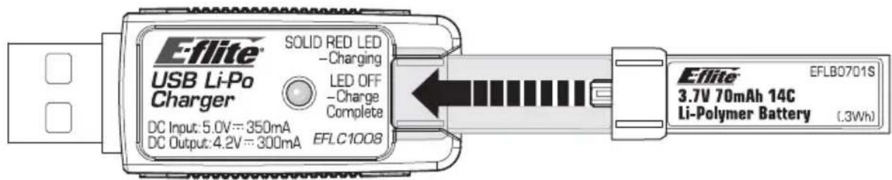
The USB battery charger (EFLC1008) included with your aircraft has been designed to safely charge the Li-Po battery.

CAUTION: All instructions and warnings must be followed exactly. Mishandling of batteries can result in a fire, personal injury or property damage.
- NEVER LEAVE CHARGING BATTERIES UNATTENDED.
• NEVER CHARGE BATTERIES OVERNIGHT. - By handling, charging or using the included Li-Po battery, you assume all risks associated with lithium batteries.
- If at any time the battery begins to balloon or swell, discontinue use immediately. If charging or discharging, discontinue and disconnect. Continuing to use, charge or discharge a battery that is ballooning or swelling can result in fi re.
- Always store the battery at room temperature in a dry area for best results.
- Always transport or temporarily store the battery in a temperature range of 40–120°F (5–49°C). Do not store the battery or model in a car or direct sunlight. If stored in a hot car, the battery can be damaged or even catch fire.
Low Voltage Cutoff (LVC)
When a Li-Po battery is discharged below 3V per cell, it will not hold a charge. The aircraft's ESC protects the fl light battery from over-discharge using Low Voltage Cutoff (LVC). Before the battery charge decreases too much, LVC removes power supplied to the motor. Power to the motor quickly decreases and increases, showing that some battery power is reserved for fl light control and safe landing.
When the motor power pulses, land the aircraft immediately and recharge the flight battery.
- Always charge batteries away from fl ammable materials.
• Always inspect the battery before charging. - Always disconnect the battery after charging, and let the charger cool between charges.
- Always constantly monitor the temperature of the battery pack while charging.
- ONLY USE A CHARGER SPECIFICALLY DESIGNED TO CHARGE LI-PO BATTERIES. Failure to charge the battery with a compatible charger may cause a fi re resulting in personal injury and/or property damage.
- Never discharge Li-Po cells to below 3V under load.
- Never cover warning labels with hook and loop strips.
- Never charge batteries outside recommended levels.
- Never charge damaged batteries.
- Never attempt to dismantle or alter the charger.
- Never allow minors to charge battery packs.
- Never charge batteries in extremely hot or cold places (recommended between 40–120° F or (5–49° C) or place in direct sunlight.
Disconnect and remove the Li-Po battery from the aircraft after use to prevent trickle discharge. Fully charge your Li-Po battery before storing it. During storage, make sure the battery charge does not fall below 3V per cell.
For your first lights, set your transmitter timer or a stopwatch to 5 minutes. Adjust your timer for longer or shorter lights once you have flown the model. Flights of 6 minutes or more are achievable if using proper throttle management.
NOTICE: Repeated fl ying to LVC will damage the battery.
Charging the Battery
NOTICE: Charge only batteries that are cool to the touch and are not damaged. Look at the battery to make sure it is not damaged e.g., swollen, bent, broken or punctured.

CAUTION: Only use chargers specifi cally designed to charge the included Li-Po battery. Failure to do so could result in fi re, g injury or property damage.

CAUTION: Never exceed the recommended charge rate.
- Insert the charger into a USB port. The charger only uses power from the USB port, it will not connect to your computer. USB power supplies, such as those used to charge cellular phones, can also be used.
-
Slide the battery into the slot on the charger and press it into the charge jack/connector located at the bottom of the slot. The end cap of the battery is specifically designed to allow the battery to fit into the slot one way (usually with the label on the battery facing outward) to prevent reverse polarity connection. However, check for proper alignment and polarity.
-
Always disconnect the flight battery from the charger immediately upon completion of charging.
- Remove the charger from the power supply.
LED Indications
When you make the connection successfully, the LED on the charger turns solid red, indicating charging has begun. Charging a fully discharged (not over-discharged) 70mAh battery takes approximately 30–40 minutes. The light goes out when the charge is complete.
CHARGING (Solid Red)
MAX CHARGE (OFF)

CAUTION: Once charging is complete, immediately remove the battery. Never leave a battery connected to the charger.
Your MLP4 4-channel DSM2 ® /DSMX ® RTF transmitter comes pre-bound to the aircraft.
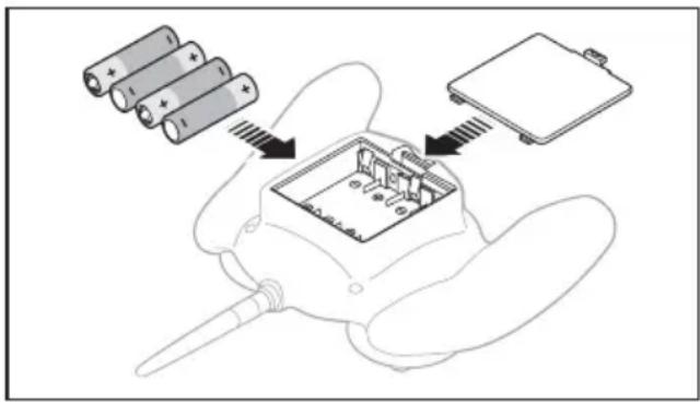
Remove the cover, install four of the included batteries (noting proper polarity) and reinstall the cover.

CAUTION: If using rechargeable batteries, charge only rechargeable batteries. Charging rechargeable batteries may cause the batteries first, resulting in injury to persons and/or age to property.

Transmitter and Receiver Binding
Binding is the process of programming the receiver of the control unit to recognize the GUID (Globally Unique Identifi er) code of a single specifi c transmitter. You need to 'bind' your chosen Spektrum DSM® technology equipped aircraft transmitter to the receiver for proper operation.
For a list of compatible DSM2®/DSMX® transmitters, please visit www.bindnfl y.com.

CAUTION: When using a Futaba® transmitter with a Spektrum DSM module, you must reverse the throttle channel and rebind. Refer to your Spektrum module manual for binding and failsafe cctions. Refer to your Futaba transmitter manual for instructions on reversing the throttle channel.

Binding Procedure Reference Table
| 1. Refer to your transmitter's unique instructions for binding to a receiver. | |
| 2. Make sure the fl ight battery is disconnected from the aircraft. | |
| 3. Ensure the transmitter is powered OFF | |
| 4. Connect the fl ight battery to the aircraft. The receiver LED will begin to fl ash (typically after 5 seconds). | |
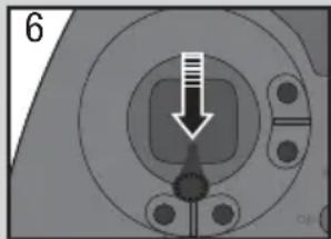
| 5. Put your transmitter into bind mode. If you are using the transmitter that is supplied with the RTF version, push the left control stick vertically into the case (until it clicks) while powering ON the transmitter. | |
| 6. Make sure the transmitter controls are at neutral and the throttle is in the low position. | |
| 7. After 5 to 10 seconds, the receiver status LED will become solid, indicating that the receiver is bound to the transmitter. If the LED does not turn solid, refer to the Troubleshooting Guide at the end of the manual. |

For subsequent f lights, power on the transmitter for 5 seconds before connecting the flight battery.
Installing the Flight Battery and Arming the ESC
Arming the ESC also occurs after binding as previously described, but subsequent connection of a flight battery requires the following steps.

CAUTION: Always keep hands away from propeller. When armed, motor will turn the propeller in sense to any throttle movement.

CAUTION: Always disconnect the Li-Po battery from the aircraft over when not flying to avoid discharging the battery. Batteries charged to a voltage lower than the st approved voltage may become charged, resulting in loss of remance and potential fire when series are charged.
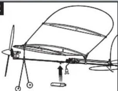
Lower throttle and throttle trim to lowest settings.

Power ON the Transmitter, then wait 5 seconds
Secure the battery to the hook and loop strip on the battery holder. Connect the battery to the ESC, noting proper polarity.
1

2


Continuous LED
Preflight Checklist
| √ | |
| 1. Charge the fl ight battery. | |
| 2. Turn on the transmitter. | |
| 3. Install the fl ight battery in the aircraft (once it has been fully charged). | |
| 4. Make sure the linkages move freely. |
| √ | |
| 5. Perform the Control Direction Test with the transmitter. | |
| 6. Adjust the center of gravity. | |
| 7. Find a safe and open area. | |
| 8. Plan fl ight appropriate for fl ying location. |
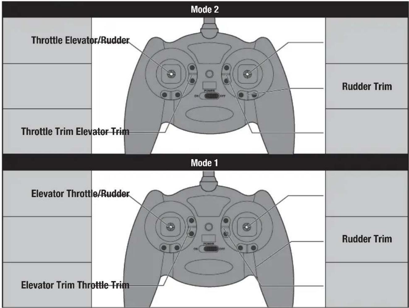
Digital Trims
The E-Flite® 4-channel DSM2®/DSMX® transmitter features digital trim buttons on all controls to make fi ne adjustments. The digital trims are used to fi ne-tune the model's fl ight path when in fl ight.
Before the first flight, center the control surfaces mechanically (see Control Centering).
When pressed down, trim buttons make a sound that increases or decreases in pitch at each pressing. The middle or neutral trim position is heard as a middle tone in the pitch range of the sounds. The end of the control range is sounded by a series of beeps.
Dual Rate Function
This transmitter's dual rate feature lets you change between high and low control rates for the elevator and rudder.
- When powered ON, this transmitter is automatically set to high-rate mode.
- Change rate modes by pushing the right-hand control stick vertically into the case (until it clicks) while the transmitter is powered on.
- High-rate mode is shown by the transmitter's LED glowing solid red. In high-rate mode, the controls can reach their maximum values. This mode is typically preferred by experienced pilots for maximum control authority.
- Low-rate mode is shown by the transmitter's LED blinking continuously. In low-rate mode, the controls are reduced to approximately 70% of their maximum values. This mode is typically preferred by (and best for) beginner pilots or others interested in smoother and more easily controlled flight.
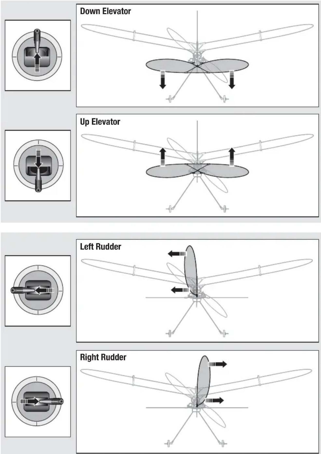
Control Direction Test
Bind your aircraft and transmitter before doing these tests. Move the controls on the transmitter to make sure aircraft control surfaces move correctly. Always keep throttle at the low position during testing.
Reverse Controls
NOTICE: The Vapor® Lite HP RTF should not require any servo reversing. Should the Vapor® Lite HP electronic components be used in another aircraft, you may find it necessary to reverse the operation of the flight control surfaces.
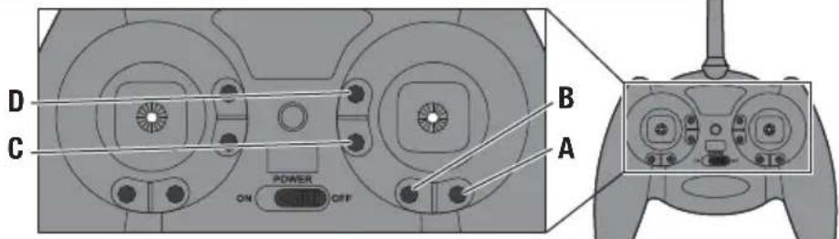
A Rudder Reversed
B Rudder Normal
C Elevator Reversed
D Elevator Normal
The transmitter included with the aircraft is the same transmitter included in other E-Flite® and ParkZone® Ultra Micro RTF models.
- Ensure the battery is disconnected from the aircraft and the transmitter is turned OFF.
- Press and hold the digital trim button for the surface you would like to reverse.
-
While holding the digital trim button, turn the transmitter ON.
-
Hold the digital trim buttons down for approximately 5 seconds until you hear a tone confirming the selection.
- Connect the flight battery and complete the flight control test. Confirm all surfaces operate in the correct direction.
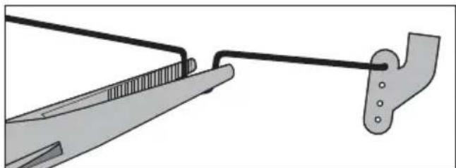
Control Centering
Before first lights, or in the event of an accident, make sure the light control surfaces are centered. Adjust the linkages mechanically if the control surfaces are not centered.
Use of the transmitter trims may not correctly center the aircraft control surfaces due to the mechanical limits of linear servos.
- Make sure the control surfaces are neutral when the transmitter controls and trims are centered. The transmitter sub-trim must be set to zero.
- When needed, use a pair of pliers to carefully bend the metal of the linkage (see illustration).
- Make the U-shape narrower to make the connector shorter. Make the U-shape wider to make the linkage longer.
NOTICE: When using a programmable transmitter, do not use Sub-Trim to adjust the center position of the servo.
NOTICE: Never set Travel Adjust above 100%. Ultra Micro servos are unique in that they are calibrated to reach maximum travel at 100% travel adjust. Increasing the value above 100% will NOT result in more travel, but can cause the servo to lock and will result in a crash.
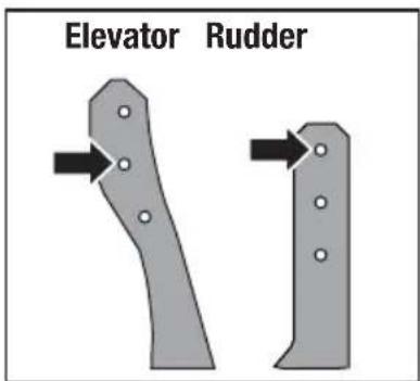
Settings for Control Horns
The illustration shows factory settings for linkages on the control horns. After flying, if you want to modify control throw, carefully adjust the linkage positions for desired control response.
Control Rates
We recommend using a DSM2/DSMX aircraft transmitter capable of dual rates. Adjust according to individual preferences after initial flight.
It is normal for linear servos to make noise. Noise is not an indication of a faulty servo.
To achieve the proper Low Rate settings when using a programmable DSM aircraft transmitter, set the low rate value to 70% for elevator and rudder.
| High Rate Low Rate | ||
| Elevator 100% 70% | ||
| Rudder 100% 70% | ||
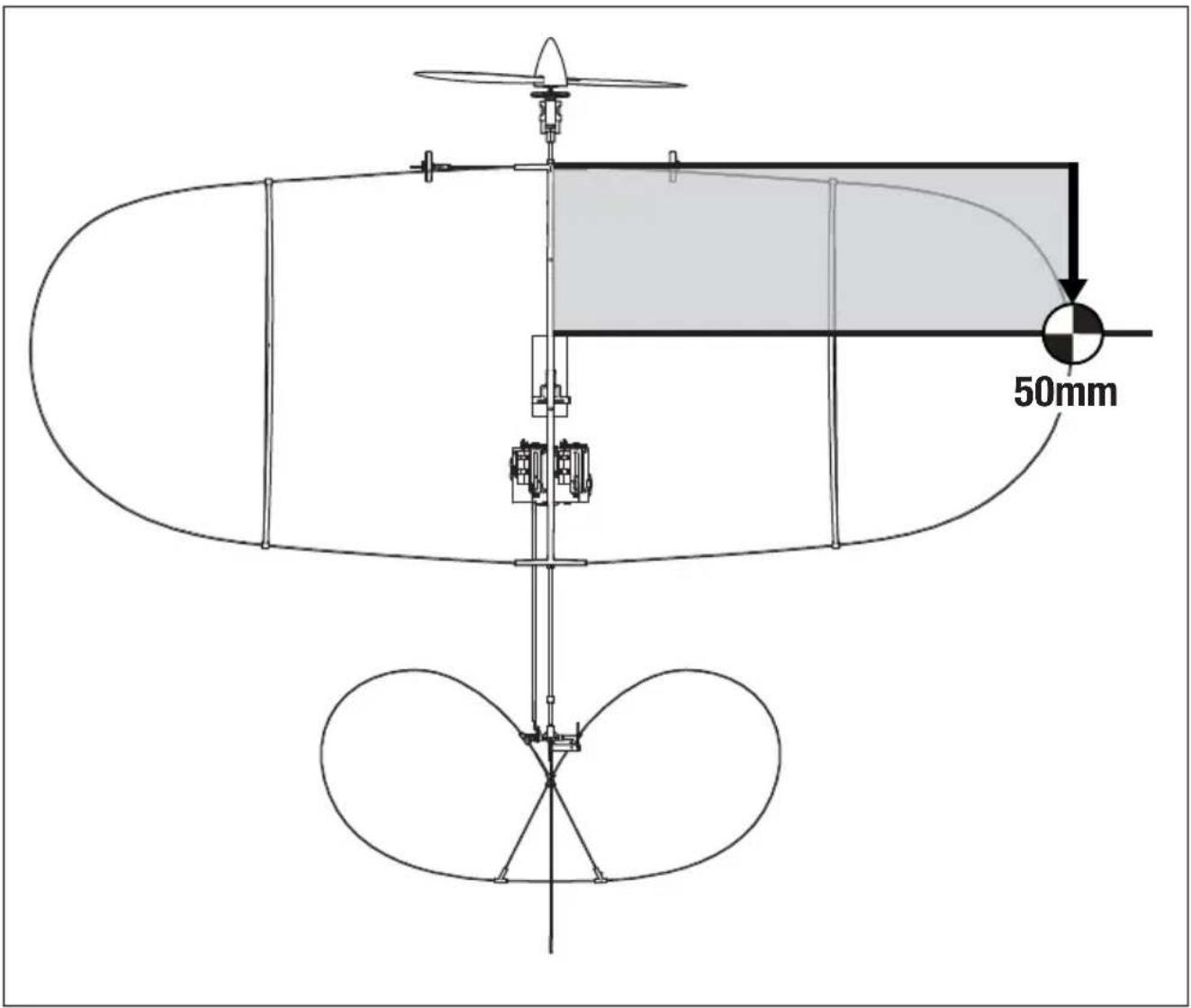
Adjusting Center of Gravity (CG)
The CG location is 50mm back from the leading edge of the center of the wing.
This CG location has been determined with the included 1S 70mAh 3.7V Li-Po battery installed in the battery holder.
Balance the model on the edge of a metal ruler to find the Center of Gravity. Place the ruler on the underside side of the airframe.
Motor Service

CAUTION: DO NOT handle propeller parts while the flight battery is connected.
Personal injury could result.
Disassembly
- Disconnect the battery from the ESC/receiver.
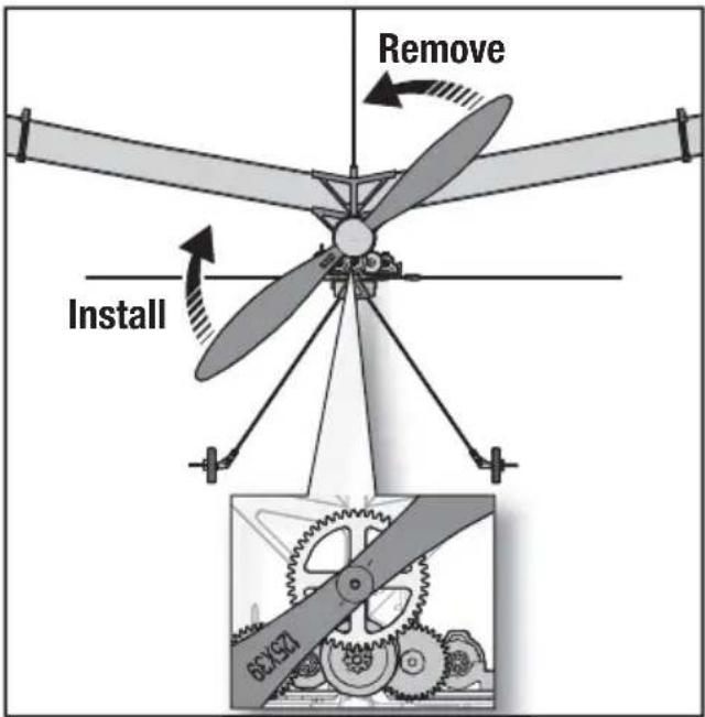
- Hold the spur gear and turn the propeller counterclockwise (looking from the front of the model) to remove. Turn the propeller clockwise to install. Make sure the propeller size numbers (125 x 39) face away from the motor (see illustration).
- Hold the nut on the end of the prop shaft using needle-nose pliers or hemostats.
- Turn the gear on the shaft clockwise (looking from front of model) to remove the nut.
- Gently pull the shaft (A) from the gearbox (B) and make sure the washer (C) and two bushings (D) are not lost.
- Disconnect the motor from the ESC/receiver.
- Gently push the motor out of the gearbox and remove the motor.
NOTICE: DO NOT remove the gearbox from the aircraft. Damage to the aircraft will result.
Assembly
Assemble the aircraft using the instructions above in reverse order.
- Correctly align the prop shaft gear with the pinion gear on the motor.
- Correctly connect the motor to the ESC/receiver so that the powered motor turns the propeller clockwise (looking from the front of the model).

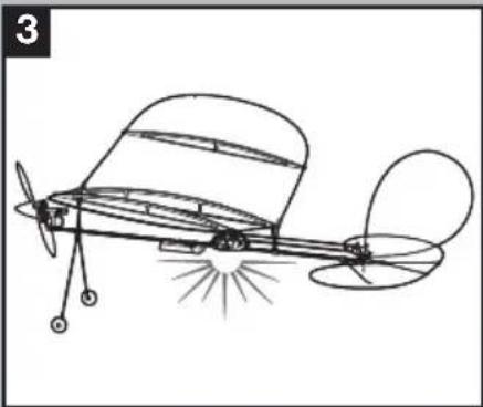
Flying Tips and Repairs
We recommend fl ying your aircraft indoors with a fl oor area of 15 ft x 15 ft and a minimum ceiling height of 8 ft; a living room or offi ce is ideal. We suggest fi rst fl ights take place in a larger area, like a garage or basement.
We do not recommend fl ying outdoors unless the conditions are absolutely calm. The aircraft is extremely light and can be easily blown away.
Hand Launching
Hold the aircraft at shoulder height with one hand. While holding your transmitter in your other hand, increase the throttle to half. Launch the aircraft using light force. Keep the wings level and do not throw it up or down. Point it level with the ground when releasing. Do not grasp the pushrods while launching, as this may result in damage to the servos.
Runway Takeoff
Place the aircraft in position for takeoff. Gradually increase the throttle to full and steer with the rudder. Pull back gently with the elevator and climb to check trim. Once the trim is adjusted, begin exploring the flight envelope.
Flying
After takeoff, the aircraft will climb at 3/4 to full throttle. The UMX™ Vapor® Lite HP aircraft is
designed for a slow and relaxing flight experience. Fly at a slow, controlled speed appropriate for the size of the location.
Landing
Fly the aircraft to approximately 6 inches (15cm) or less above the landing surface. Reduce the throttle and the aircraft should glide in softly for a landing.
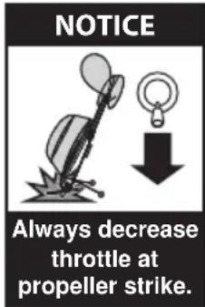
Failure to lower the throttle stick and trim to the lowest possible positions during a crash could result in damage to the ESC in the receiver unit, which may require replacement.
NOTICE: Crash damage is not covered under warranty.
Repairs
Repair the aircraft using clear tape. When parts are not repairable, see the Replacement Parts List for ordering by item number.
For a listing of all replacement and optional parts, refer to the list at the back of this manual.
Additional Safety Precautions and Warnings
As the user of this product, you are solely responsible for operating it in a manner that does not endanger yourself and others or result in damage to the product or the property of others.
- Always keep a safe distance in all directions around your model to avoid collisions or injury.
This model is controlled by a radio signal subject to interference from many sources outside your control. Interference can cause momentary loss of control. - Always operate your model in open spaces away from full-size vehicles, traffic and people.
- Always carefully follow the directions and warnings for this and any optional support equipment (chargers, rechargeable battery packs, etc.).
- Always keep all chemicals, small parts and anything electrical out of the reach of children.
-
Always avoid water exposure to all equipment not specifi cally designed and protected for this purpose. Moisture causes damage to electronics.
-
Never place any portion of the model in your mouth as it could cause serious injury or even death.
- Never operate your model with low transmitter batteries.
- Always keep the aircraft in sight and under control.
• Always use fully charged batteries. - Always keep the transmitter powered ON while the aircraft is powered.
• Always remove batteries before disassembly.
• Always keep moving parts clean.
• Always keep parts dry.
• Always let parts cool after use before touching.
• Always remove batteries after use. - Always ensure failsafe is properly set before fl ying.
- Never operate aircraft with damaged wiring.
- Never touch moving parts.
Troubleshooting Guide
| Problem | Possible Cause Solution | |
| Aircraft will not respond to throttle but re-sponds to other controls | Throttle stick and/or throttle trim is too high | Reset controls with throttle stick and throttle trim at lowest setting |
| Throttle channel is reversed Reverse throttle channel on transmitter | ||
| Extra propeller noise or extra vibration | Damaged propeller, prop shaft or motor Replace damaged parts | |
| Nut on prop shaft is too loose Tighten the prop shaft nut 1/2 turn | ||
| Reduced fl ight time or aircraft underpowered | Flight battery charge is low Completely recharge fl ight battery | |
| Propeller is installed backwards Install propeller with numbers facing forward | ||
| Flight battery is damaged Replace fl ight battery and follow fl ight battery instructions | ||
| Flight conditions may be too cold Make sure battery is warm before use | ||
| Battery capacity is too low for fl ight conditions | Replace battery or use a larger capacity battery | |
| LED on receiver fl ashes rapidly and aircraft will not bind to transmitter (dur-ing binding) | Transmitter is too near aircraft during binding process | Power off transmitter, move transmitter a larger distance from aircraft, disconnect and reconnect fl ight battery to aircraft and follow binding instructions |
| Bind switch or button was not held while transmitter was powered on | Power off transmitter and repeat bind process | |
| Aircraft or transmitter is too close to large metal object, wireless source or another transmitter | Move aircraft and transmitter to another location and attempt binding again | |
| LED on receiver fl ashes rapidly and aircraft will not respond to transmitter (after binding) | Less than a 5-second wait between fi rst powering on transmitter and connecting fl ight battery to aircraft | Leaving transmitter on, disconnect and reconnect fl ight battery to aircraft |
| Aircraft is bound to a different model memory (ModelMatchTM radios only) | Select correct model memory on transmit-ter and disconnect and reconnect fl ight battery to aircraft | |
| Flight battery/transmitter battery charge is too low | Replace/recharge batteries | |
| Transmitter may have been bound to a different model (or with a different DSM Protocol) | Select the right transmitter or bind to the new one | |
| Aircraft or transmitter is too close to large metal object, wireless source or another transmitter | Move aircraft and transmitter to another location and attempt linking again | |
| Control surface does not move | Control surface, control horn, linkage or servo damage | Replace or repair damaged parts and adjust controls |
| Wire damaged or connections loose Do a check of wires and connections; con-nect or replace as needed | ||
| Flight battery charge is low Fully recharge fl ight battery | ||
| Control linkage does not move freely Make sure control linkage moves freely | ||
| Controls reversed | Transmitter settings reversed Do the Control | Direction Test and adjust controls on transmitter appropriately |
| Motor loses power | Damage to motor or power components Do | a check of motor and power components for damage (replace as needed) |
| Nut on prop shaft is too tight Loosen prop shaft | shaft nut until propeller shaft turns freely | |
| Motor power quickly decreases and increases then motor loses power | Battery power is down to the point of receiver/ESC Low Voltage Cutoff (LVC) | Recharge flight battery or replace battery that is no longer performing |
| Servo locks or freezes at full travel | Travel adjust value is set above 100% overdriving the servo | Set Travel adjust to 100% or less and/or set sub trims to Zero and adjust linkages mechanically. |
Post Flight Checklist
| √ | |
| 1. Disconnect the fl ight battery from the ESC (Required for safety and battery life). | |
| 2. Power OFF the transmitter. | |
| 3. Remove the fl ight battery from the aircraft. |
| √ | |
| 4. Recharge the fl ight battery. | |
| 5. Store the fl ight battery apart from the aircraft and monitor the battery charge. | |
| 6. Make note of the fl ight conditions and fl ight plan results, planning for future fl ights. |
Limited Warranty
What this Warranty Covers – Horizon Hobby, LLC, (Horizon) warrants to the original purchaser that the product purchased (the "Product") will be free from defects in materials and workmanship at the date of purchase.
What is Not Covered – This warranty is not transferable and does not cover (i) cosmetic damage, (ii) damage due to acts of God, accident, misuse, abuse, negligence, commercial use, or due to improper use, installation, operation or maintenance, (iii) modification of or to any part of the Product, (iv) attempted service by anyone other than a Horizon Hobby authorized service center, (v) Product not purchased from an authorized Horizon dealer, or (vi) Product not compliant with applicable technical regulations, or (vii) use that violates any applicable laws, rules, or regulations.
OTHER THAN THE EXPRESS WARRANTY ABOVE, HORIZON MAKES NO OTHER WARRANTY OR REPRESENTATION, AND HEREBY DISCLAIMS ANY AND ALL IMPLIED WARRANTIES, INCLUDING, WITHOUT LIMITATION, THE IMPLIED WARRANTIES OF NON-INFRINGEMENT, MERCHANTABILITY AND FITNESS FOR A PARTICULAR PURPOSE. THE PURCHASER ACKNOWLEDGES THAT THEY ALONE HAVE DETERMINED THAT THE PRODUCT WILL SUITABLY MEET THE REQUIREMENTS OF THE PURCHASER'S INTENDED USE.
Purchaser's Remedy – Horizon's sole obligation and purchaser's sole and exclusive remedy shall be that Horizon will, at its option, either (i) service, or (ii) replace, any Product determined by Horizon to be defective. Horizon reserves the right to inspect any and all Product(s) involved in a warranty claim. Service or replacement decisions are at the sole discretion of Horizon. Proof of purchase is required for all warranty claims. SERVICE OR REPLACEMENT AS PROVIDED UNDER THIS WARRANTY IS THE PURCHASER'S SOLE AND EXCLUSIVE REMEDY.
Limitation of Liability – HORIZON SHALL NOT BE LIABLE FOR SPECIAL, INDIRECT, INCIDENTAL OR CONSEQUENTIAL DAMAGES, LOSS OF PROFITS OR PRODUCTION OR COMMERCIAL LOSS IN ANY WAY, REGARDLESS OF WHETHER SUCH CLAIM IS BASED IN CONTRACT, WARRANTY, TORT, NEGLIGENCE, STRICT LIABILITY OR ANY OTHER THEORY OF LIABILITY, EVEN IF HORIZON HAS BEEN ADVISED OF THE POSSIBILITY OF SUCH DAMAGES. Further, in no event shall the liability of Horizon exceed the individual price of the Product on which liability is asserted. As Horizon has no control over use, setup, fi nal assembly, modifi cation or misuse, no liability shall be assumed nor accepted for any resulting damage or injury. By the act of use, setup or assembly, the user accepts all resulting liability. If you as the purchaser or user are not prepared to accept the liability associated with the use of the Product, purchaser is advised to return the Product immediately in new and unused condition to the place of purchase.
Law – These terms are governed by Illinois law (without regard to conflict of law principals). This warranty gives you specific legal rights, and you may also have other rights which vary from state to state. Horizon reserves the right to change or modify this warranty at any time without notice.
WARRANTY SERVICES
Questions, Assistance, and Services – Your local hobby store and/or place of purchase cannot provide warranty support or service. Once assembly, setup or use of the Product has been started, you must contact your local distributor or Horizon directly. This will enable Horizon to better answer your questions and service you in the event that you may need any assistance. For questions or assistance, please visit our website at www.horizonhobby.com, submit a Product Support Inquiry, or call the toll free telephone number referenced in the Warranty and Service Contact Information section to speak with a Product Support representative.
Inspection or Services – If this Product needs to be inspected or serviced and is compliant in the country you live and use the Product in, please use the Horizon Online Service Request submission process found on our website or call Horizon to obtain a Return Merchandise Authorization (RMA) number. Pack the Product securely using a shipping carton. Please note that original boxes may be included, but are not designed to withstand the rigors of shipping without additional protection. Ship via a carrier that provides tracking and insurance for lost or damaged parcels, as Horizon is not responsible for merchandise until it arrives and is accepted at our facility. An Online Service Request is available at http://www.horizonhobby.com/content/_service-center_render-service-center. If you do not have internet access, please contact Horizon Product Support to obtain a RMA number along with instructions for submitting your product for service. When calling Horizon, you will be asked to provide your complete name, street address, email address and phone number where you can be reached during business hours. When sending product into Horizon, please include your RMA number, a list of the included items, and a brief summary of the problem. A copy of your original sales receipt must be included for warranty consideration. Be sure your name, address, and RMA number are clearly written on the outside of the shipping carton.
NOTICE: Do not ship LiPo batteries to Horizon. If you have any issue with a LiPo battery, please contact the appropriate Horizon Product Support offi ce.
Warranty Requirements – For Warranty consideration, you must include your original sales receipt verifying the proof-of-purchase date. Provided warranty conditions have been met, your Product will be serviced or replaced free of charge. Service or replacement decisions are at the sole discretion of Horizon.
Non-Warranty Service – Should your service not be covered by warranty, service will be completed and payment will be required without notifi cation or estimate of the expense unless the expense exceeds 50% of the retail purchase cost. By submitting the item for service you are agreeing to payment of the service without notifi cation. Service estimates are available upon request. You must include this request with your item submitted for service. Non-warranty service estimates will be billed a minimum of 1/2 hour of labor. In addition you will be billed for return freight. Horizon accepts money orders and cashier's checks, as well as Visa, MasterCard, American Express, and Discover cards. By submitting any item to Horizon for service, you are agreeing to Horizon's Terms and Conditions found on our website http://www.horizonhobby.com/content/service-center_render-service-center.
ATTENTION: Horizon service is limited to Product compliant in the country of use and ownership. If received, a non-compliant Product will not be serviced. Further, the sender will be responsible for arranging return shipment of the un-serviced Product, through a carrier of the sender's choice and at the sender's expense. Horizon will hold non-compliant Product for a period of 60 days from notification, after which it will be discarded.
10/2015
Warranty and Service Information
| Country of Purchase | Horizon Hobby Contact Information Address | ||
| United States of America | Horizon Service Center (Repairs and Repair Requests) | servicecenter.horizonhobby.com/RequestForm/ | 4105 Fieldstone Rd Champaign, Illinois, 61822 USA |
| Horizon Product Support (Product Technical Assistance) | productsupport@horizonhobby.com | ||
| 877-504-0233 | |||
| Sales | websales@horizonhobby.com | ||
| 800-338-4639 | |||
| European Union | Horizon Technischer Service ser | service@horizonhobby.eu | Hanskampring 9 D 22885 Barsbüttel, Germany |
| Sales: Horizon Hobby GmbH +49 (0) 4121 2655 100 | |||
FCC Information
FCC ID: BRWEFLU6807 (EFLU6800 and EFLU6850)
FCC ID: BRWDXE (EFLU6800)
This equipment has been tested and found to comply with the limits for a Class B digital device, pursuant to part 15 of the FCC Rules. These limits are designed to provide reasonable protection against harmful interference in a residential installation. This equipment generates, uses and can radiate radio frequency energy and, if not installed and used in accordance with the instructions, may cause harmful interference to radio communications.
However, there is no guarantee that interference will not occur in a particular installation. If this equipment does cause harmful interference to radio or television reception, which can be determined by turning the equipment off and on, the user is encouraged to try to correct the interference by one or more of the following measures:
- Reorient or relocate the receiving antenna.
- Increase the separation between the equipment and receiver.
- Connect the equipment to an outlet on a circuit different from that to which the receiver is connected.
This device complies with part 15 of the FCC rules. Operation is subject to the following two conditions: (1) This device may not cause harmful interference, and (2) this device must accept any interference received, including interference that may cause undesired operation.
NOTICE: Modifi cations to this product will void the user's authority to operate this equipment.
This product contains a radio transmitter with wireless technology which has been tested and found to be compliant with the applicable regulations governing a radio transmitter in the 2.400GHz to 2.4835GHz frequency range.
Antenna Separation Distance
When operating your transmitter, please be sure to maintain a separation distance of at least 20 cm between your body (excluding fingers, hands, wrists, ankles and feet) and the antenna to meet RF exposure safety requirements as determined by FCC regulations.
This illustration shows the approximate 20 cm RF exposure area and typical hand placement when operating your transmitter.

This device complies with Industry Canada licence-exempt RSS standard(s). Operation is subject to the following two conditions: (1) this device may not cause interference, and (2) this device must accept any interference, including interference that may cause undesired operation of the device.
Compliance Information for the European Union

EU Compliance Statement:
EFLU6800 UMX Vapor Lite RTF: Horizon Hobby, LLC hereby declares that this product is in compliance with the essential requirements and other relevant provisions of the RED and EMC Directives.
EFLU6850 UMX Vapor Lite BNF Basic: Horizon Hobby, LLC hereby declares that this product is in compliance with the essential requirements and other relevant provisions of the RED Directive.
A copy of the EU Declaration of Conformity is available online at:
http://www.horizonhobby.com/content/support-render-compliance.
Instructions for disposal of WEEE by users in the European Union

This product must not be disposed of with other waste. Instead, it is the user's responsibility to dispose of their waste equipment by handing it over to a designated collections point for the recycling of waste electrical and electronic equipment. The separate collection and recycling of your waste equipment at
the time of disposal will help to conserve natural resources and ensure that it is recycled in a manner that protects human health and the environment. For more information about where you can drop off your waste equipment for recycling, please contact your local city office,

your household waste disposal service or where you purchased the product.
E328
© 2017 Horizon Hobby, LLC.
E-flite, Vapor, AS3X, DSM, DSM2, DSMX, Bind-N-Fly, BNF, the BNF logo, ModelMatch, and the Horizon Hobby logo are trademarks or registered trademarks of Horizon Hobby, LLC.
The Spektrum trademark is used with permission of Bachmann Industries, Inc.
Futaba is a registered trademark of Futaba Denshi Kogyo Kabushiki Kaisha Corporation of Japan.
All other trademarks, service marks and logos are property of their respective owners.
US D7774,933. US 8,672,726.
http://www.e-fliterc.com/


- MEANING OF SPECIAL LANGUAGE
- AGE RECOMMENDATION: NOT FOR CHILDREN UNDER 14 YEARS. THIS IS NOT A TOY
- BOX CONTENTS
- TABLE OF CONTENTS
- SPECIFICATIONS
- CHARGING WARNINGS
- LOW VOLTAGE CUTOFF (LVC)
- CHARGING THE BATTERY
- LED INDICATIONS
- TRANSMITTER AND RECEIVER BINDING
- INSTALLING THE FLIGHT BATTERY AND ARMING THE ESC
- PREFLIGHT CHECKLIST
- DIGITAL TRIMS
- DUAL RATE FUNCTION
- CONTROL DIRECTION TEST
- REVERSE CONTROLS
- CONTROL CENTERING
- SETTINGS FOR CONTROL HORNS
- CONTROL RATES
- ADJUSTING CENTER OF GRAVITY (CG)
- MOTOR SERVICE
- DISASSEMBLY
- ASSEMBLY
- FLYING TIPS AND REPAIRS
- HAND LAUNCHING
- RUNWAY TAKEOFF
- FLYING
- LANDING
- REPAIRS
- ADDITIONAL SAFETY PRECAUTIONS AND WARNINGS
- LIMITED WARRANTY
- WARRANTY SERVICES
- FCC INFORMATION
- ANTENNA SEPARATION DISTANCE
- COMPLIANCE INFORMATION FOR THE EUROPEAN UNION
- EU COMPLIANCE STATEMENT
- INSTRUCTIONS FOR DISPOSAL OF WEEE BY USERS IN THE EUROPEAN UNION
Brand : E-flite
Model : EFLU6800
Category : Remote control toy