
ISW-804PT-M12 - Switch Planet - Free user manual and instructions
Find the device manual for free ISW-804PT-M12 Planet in PDF.


| Product Type | Industrial IP67 Rated 8-Port 10/100Mbps M12 Ethernet Switch with 4-Port PoE (ISW-804PT-M12) |
| Dimensions (W x D x H) | 163 x 103 x 53 mm |
| Weight | 976 g |
| Power Input | 48V DC, redundant power with polarity reverse protection |
| Power Consumption | 65 Watts (max) / 221 BTU |
| Ethernet Ports | 8 x M12, 4-pin D-coded female connector (10/100Base-TX) |
| PoE Ports | 4 ports (Port 5-8), IEEE 802.3af, up to 15.4W per port, total PoE budget 60W |
| Switching Fabric | 1.6 Gbps |
| MAC Address Table | 2K entries |
| Throughput (64-byte packets) | 1.19 Mpps |
| Flow Control | Back pressure (half-duplex), IEEE 802.3x PAUSE frame (full-duplex) |
| Enclosure | IP67 aluminum metal case |
| Operating Temperature | -40°C to 75°C |
| Storage Temperature | -40°C to 75°C |
| Humidity | 5% to 95% (non-condensing) |
| ESD Protection | 6,000 VDC (Ethernet) |
| EFT Protection | 6,000 VDC (power line) |
| Standards Compliance | IEEE 802.3, 802.3u, 802.3x, 802.3af; FCC Part 15 Class A, CE |
| Installation | DIN rail or wall mount (brackets included) |
| Package Contents | Switch, user manual, 1.2m M12-to-RJ45 UTP cable, 1.2m M12 power cable, DIN rail kit, wall mount kit |
| Maintenance | Clean with a dry cloth. No user-serviceable parts inside. |
| Safety | Use only with specified 48V DC supply. Do not open the enclosure. Keep away from moisture. |
Frequently Asked Questions - ISW-804PT-M12 Planet
User questions about ISW-804PT-M12 Planet
0 question about this device. Answer the ones you know or ask your own.
Ask a new question about this device
Download the instructions for your Switch in PDF format for free! Find your manual ISW-804PT-M12 - Planet and take your electronic device back in hand. On this page are published all the documents necessary for the use of your device. ISW-804PT-M12 by Planet.
USER MANUAL ISW-804PT-M12 Planet
Industrial IP67 Rated 8-Port 10/100Mbps M12 Ethernet Switch
ISW-800T-M12 & ISW-804PT-M12
User's Manual
Trademarks
Copyright © PLANET Technology Corp. 2011.
Contents subject to revision without prior notice.
PLANET is a registered trademark of PLANET Technology Corp. All other trademarks belong to their respective owners.
Disclaimer
PLANET Technology does not warrant that the hardware will work properly in all environments and applications, and makes no warranty and representation, either implied or expressed, with respect to the quality, performance, merchantability, or fitness for a particular purpose.
PLANET has made every effort to ensure that this User's Manual is accurate; PLANET disclaims liability for any inaccuracies or omissions that may have occurred.
Information in this User's Manual is subject to change without notice and does not represent a commitment on the part of PLANET. PLANET assumes no responsibility for any inaccuracies that may be contained in this User's Manual. PLANET makes no commitment to update or keep current the information in this User's Manual, and reserves the right to make improvements to this User's Manual and/or to the products described in this User's Manual, at any time without notice.
If you find information in this manual that is incorrect, misleading, or incomplete, we would appreciate your comments and suggestions.
FCC Warning
This equipment has been tested and found to comply with the limits for a Class A digital device, pursuant to Part 15 of the FCC Rules. These limits are designed to provide reasonable protection against harmful interference when the equipment is operated in a commercial environment. This equipment generates, uses, and can radiate radio frequency energy and, if not installed and used in accordance with the Instruction manual, may cause harmful interference to radio communications. Operation of this equipment in a residential area is likely to cause harmful interference in which case the user will be required to correct the interference at his own expense.
CE Mark Warning
This is a Class A product. In a domestic environment, this product may cause radio interference, in which case the user may be required to take adequate measures.
WEEE Warning
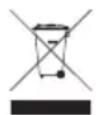
To avoid the potential effects on the environment and human health as a result of the presence of hazardous substances in electrical and electronic equipment, end users of electrical and electronic equipment should understand the meaning of the crossed-out wheeled bin symbol. Do not dispose of WEEE as unsorted municipal waste and have to collect such WEEE separately.
Revision
PLANET Industrial IP67 Rated 8-Port 10/100Mbps M12 Ethernet Switch User's Manual
For Models: ISW-800T-M12 & ISW-804PT-M12
Revision: 1.0 (August, 2011)
Part No: EM-ISW-800T-M12_804PT-M12_v1.0 (2350-AH0450-000)
Table of Contents
1. Introduction .... 5
1.1 Package Contents.... 5
1.2 How to Use This Manual.... 5
1.3 Product Features 6
1.4 Product Specifications .... 7
1.5 Physical Dimension....10
2. Installation 12
2.1 Product Description....12
2.1.1 Product Overview ...... 13
2.1.2 Switch Front Panel 13
2.1.3 LED Indicators 14
2.1.4 M12 DC Power Cable Pinout....14
2.1.5 10/100Mbps Ports with M12 Interface Cable Pinout....15
2.2 Mounting Installation 16
2.2.1 DIN-Rail Mounting....16
2.2.2 Wall Mount Plate Mounting....17
3. Applicaiton ....18
4. Power Over Ethernet Overview ......22
5. Troubleshooting ....25
Appendix A: Networking Connection ....26
A.1 Switch's RJ-45 Pin Assignments 26
A.2 RJ-45 Cable Pin Assignments....26
1. Introduction
1.1 Package Contents
Check the contents of your package for following parts:
Industrial IP67 Rated M12 Ethernet Switch x 1 ●
User's Manual x 1 ●
1.2m M12-to-RJ45 UTP Cable x 1 ●
1.2m M12 Power Cable x 1 ●
DIN Rail Kit x 1 ●
Wall Mount Kit x 1 ●
If any of these are missing or damaged, please contact your dealer immediately, if possible, retain the carton including the original packing material, and use them against to repack the product in case there is a need to return it to us for repair.
In the following section, the term "Industrial M12 Ethernet Switch" means the ISW-800T-M12 and ISW-804PT-M12.
1.2 How to Use This Manual
This Industrial M12 Ethernet Switch User Manual is structured as follows:
Chapter 2 Installation
The chapter explains the feature, functionality and the physical installation of the Industrial M12 Ethernet Switch.
Chapter 3 Application
The chapter explains the Industrial M12 Ethernet Switch application.
Chapter 4 Power over Ethernet overview (ISW-804PT-M12 only)
The section explains the IEEE 802.3af Power over Ethernet theories.
Chapter 5 Troubleshooting
The chapter explains the troubleshooting of the Industrial M12 Ethernet Switch.
Appendix A
This chapter contains cable information of the Industrial M12 Ethernet Switch.
1.3 Product Features
Physical Port
8-Port 10/100Mbps M12 Connector with IP67 protection ●
● 4-Port IEEE 802.3af PoE Ports (ISW-804PT-M12) (Port 5 to port 8)
Layer 2 Features
Supports Auto-negotiation and 10/100Mbps half / full duplex mode ●
- High performance Store and Forward architecture, runt/CRC filtering eliminates erroneous packets to optimize the network bandwidth
- Prevents packet loss with back pressure (Half-Duplex) and IEEE 802.3x PAUSE frame flow control (Full-Duplex)
Backplane (Switching Fabric): 1.6Gbps ●
- Integrated address look-up engine, support 2K absolute MAC addresses Automatic address learning and address aging ●
●CSMA/CD Protocol
Industrial Case / Installation
●IP67 Aluminum metal case / Protection
●DIN Rail and Wall Mount Design
●Waterproof / dustproof design
- 12 to 48V DC, redundant power with polarity reverse protect function and connective removable terminal block for master and slave power (ISW-800T-M12)
- 48V DC, redundant power with polarity reverse protect function and connective removable terminal block for master and slave power (ISW-804PT-M12)
● Supports EFT protection 6000 VDC for power line
● Supports 6000 VDC Ethernet ESD protection
- -40 to 75 Degree C operating temperature
1.4 Product Specifications
| Model ISW-800T-M12 | |
| Hardware Specification | |
| 10/100Base-TX Ports 8 x M12, 4-Pin D-coded female connector | |
| Power Connector 1 x M12, 5-Pin A-Coded male connector | |
| Enclosure IP67 Aluminum | |
| Dimension (W x D x H) 163 x 103 x 53 mm | |
| Weight 976g | |
| Power Requirement | 12~48V DC, Redundant power with polarity reverse protection function |
| Power Consumption / Dissipation 4 Watts / 13 BTU | |
| Installation DIN rail kit and wall mount ear | |
| ESD Protection 6KV DC | |
| EFT Protection 6KV DC | |
| LED Indicators | Power LED: Power 1 / Power 2 (Green), FAULT (Green)10/100Base-TX Port (Port-1 to Port-8): LNK/ACT (Green) |
| Network Cables | 10Base-T: 2-Pair UTP Cat.3,4,5 up to 100m (328ft)100Base-TX: 2-Pair UTP Cat.5, 5e, 6 up to 100m (328ft)EIA/TIA-568 100-ohm STP (100m, max.) |
| Switch Specification | |
| Switch Processing Scheme Store-and-Forward | |
| Address Table 2K entries | |
| Flow Control | Back pressure for half duplexIEEE 802.3x Pause Frame for full duplex |
| Switch Fabric | 1.6Gbps |
| Throughput (packet per second) | 1.19Mpps@64Bytes |
| Maximum Transmit Unit 1536 bytes | |
| Standards Conformance | |
| Standards Compliance | IEEE 802.3 EthernetIEEE 802.3u Fast EthernetIEEE 802.3x Full-Duplex Flow Control |
| Regulation Compliance | FCC Part 15 Class A, CE |
| Stability Testing | IEC60068-2-32 (Free fall)IEC60068-2-27 (Shock)IEC60068-2-6 (Vibration) |
| Environment | |
| Temperature | Operating: -40~75 Degree CStorage: -40~75 Degree C |
| Humidity | Operating: 5~95% (Non-condensing)Storage: 5~95% (Non-condensing) |
| Model ISW-804PT-M12 | |
| Hardware Specification | |
| 10/100Base-TX Ports 8 x M12, 4-Pin D-coded female connector | |
| IEEE 802.3af PoE Ports 4, port 5 to port 8 | |
| Power Connector 1 x M12, 5-Pin A-Coded male connector | |
| Enclosure IP67 Aluminum | |
| Dimension (W x D x H) 163 x 103 x 53 mm | |
| Weight 976g | |
| Power Requirement | 48V DC, Redundant power with polarity reverse protection function |
| Power Consumption / Dissipation 65 Watts / 221 BTU | |
| Installation DIN rail kit and wall mount ear | |
| ESD Protection 6KV DC | |
| EFT Protection 6KV DC | |
| LED Indicators | Power LED: Power 1 / Power 2 (Green), FAULT (Green)10/100Base-TX Port (Port-1 to Port-8): LNK/ACT (Green)PoE Port (Port-5 to Port-8): PoE In-Use (Orange) |
| Network Cables | 10Base-T: 2-Pair UTP Cat.3,4,5 up to 100m (328ft)100Base-TX: 2-Pair UTP Cat.5, 5e, 6 up to 100m (328ft)EIA/TIA-568 100-ohm STP (100m, max.) |
| Switch Specification | |
| Switch Processing Scheme | Store-and-Forward |
| Address Table | 2K entries |
| Flow Control | Back pressure for half duplexIEEE 802.3x Pause Frame for full duplex |
| Switch Fabric | 1.6Gbps |
| Throughput (packet per second) | 1.19Mpps@64Bytes |
| Maximum Transmit Unit | 1536 bytes |
| Standards Conformance | |
| Standards Compliance | IEEE 802.3 EthernetIEEE 802.3u Fast EthernetIEEE 802.3x Full-Duplex Flow ControlIEEE 802.3af Power over Ethernet |
| Regulation Compliance | FCC Part 15 Class A, CE |
| Stability Testing | IEC60068-2-32 (Free fall)IEC60068-2-27 (Shock)IEC60068-2-6 (Vibration) |
| Power over Ethernet | |
| PoE Standard IEEE 802.3af Power over Ethernet / PSE | |
| PoE Power Supply Type End-Span | |
| PoE Power Output 48V DC Per Port, | 350mA. Max. 15.4 Watts |
| Power Pin Assignment 1/2(+), 3/6(-) | |
| PoE Budget 60 Watts | |
| Environment | |
| Temperature | Operating: -40~75 Degree CStorage: -40~75 Degree C |
| Humidity | Operating: 5~95% (Non-condensing)Storage: 5~95% (Non-condensing) |
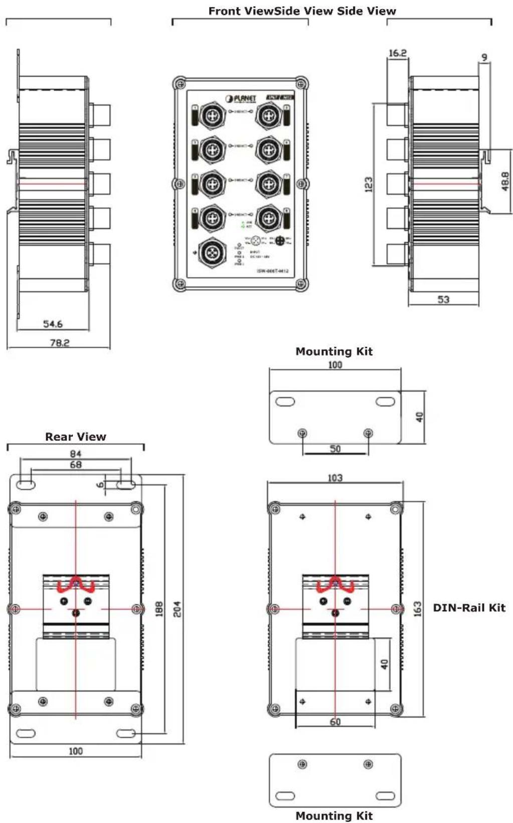
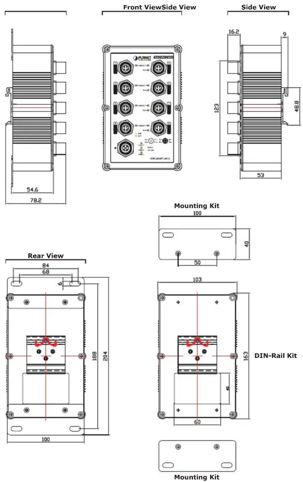
1.5 Physical Dimension
■ ISW-800T-M12 Industrial M12 Ethernet Switch dimension (W x D x H): 163 x 103 x 53mm
■ ISW-804PT-M12 Industrial M12 Ethernet Switch dimension (W x D x H): 163 x 103 x 53mm
2. Installation
This section describes the functionalities of the Industrial M12 Ethernet Switch's components and guides how to install it on the desktop. Basic knowledge of networking is assumed. Please read this chapter completely before continuing.
2.1 Product Description
The Industrial M12 Ethernet Switch equipped with IP67 industrial case protection, the Industrial M12 Ethernet Switch provides a high level of immunity against electromagnetic interference and heavy electrical surges which are usually found on plant floors or in curb side traffic control cabinets. The compact, IP67 standard metal case of Industrial M12 Ethernet Switch allows either DIN rail or wall mounting for efficient use of cabinet space.
Being able to operate under the temperature range from -40 to 75 Degree C, the Industrial M12 Ethernet Switch can be placed in almost any difficult environment. The Industrial M12 Ethernet Switch also possesses an integrated power supply source with wide range of voltages (ISW-800T-M12 with 12 to 48V DC) and (ISW-804PT-M12 with 48V DC) for worldwide high availability applications requiring dual or backup power inputs.
The ISW-800T-M12 equipped with eight 10/100Base-TX auto-negotiation ports M12 connector, the ISW-804PT-M12 equipped with eight 10/100Base-TX auto-negotiation ports M12 connector with 4-Port IEEE 802.3af PoE Ports (Port 5 to port 8); per PoE port provide 15.4 Watts PoE output. The M12 connector provides tightly and strong connection and guarantee stable Ethernet operation performance under high vibration and shock environment.
The Industrial M12 Ethernet Switch has 2K MAC Address table and offers wire-speed packets transfer performance without risk of packet loss, the high data throughput of the device makes it ideal for most Fast Ethernet environments. With a 1.6Gbps internal switching fabric and featuring auto negotiation support in each Fast Ethernet port, the Industrial M12 Ethernet Switch can handle large amounts of data in a secure topology linking to a backbone or high capacity servers.
The flow control function enables the Industrial M12 Ethernet Switch to provide fast and reliable data transfer, all of the M12 RJ-45 copper interfaces in the Industrial M12 Ethernet Switch support 10/100Mbps Auto-Negotiation for optimal speed detection through RJ-45 Category 3, 4, 5, 5e, 6 cables. The standard Auto-MDI/MDI-X support can detect the type of connection to any Ethernet device without requiring special straight or crossover cables.
2.1.1 Product Overview
The PLANET Industrial M12 Ethernet Switch with 8 RJ-45 10/100Mbps ports M12 interfaces, for high-speed network connectivity. The Industrial M12 Ethernet Switch can also automatically identify and determine the correct transmission speed and half / full duplex mode of the attached devices with its 8 Fast Ethernet ports. The M12 Fast Ethernet ports can handle extremely large amounts of data transmission in a secure topology linking to a backbone or high-power servers, the ISW-804PT-M12 also provide 4 IEEE 802.3af Fast Ethernet PoE ports and per PoE port provide 15.4 Watts PoE power output. It is an ideal solution to fill the demand of Industrial environment PoE application.
The Industrial M12 Ethernet Switch also supports Store-and-Forward forwarding scheme to ensure low latency and high data integrity, eliminates unnecessary traffic and relieves congestion on critical network paths. With an intelligent address recognition algorithm, the Industrial M12 Ethernet Switch could recognize up to 2K different MAC address and enables filtering and forwarding at full wire speed.
2.1.2 Switch Front Panel
Figure 2-1 & 2-2 shows a front panel of Industrial M12 Ethernet Switch.
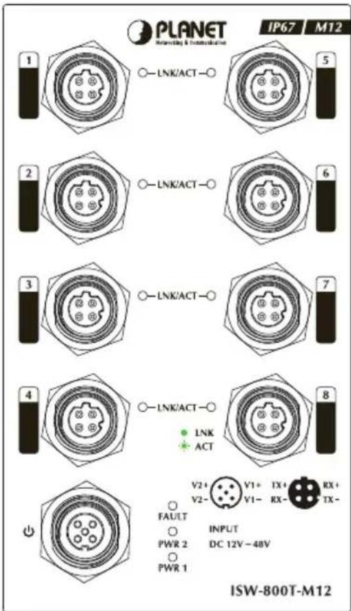
Figure 2-1: ISW-800T-M12 front panel
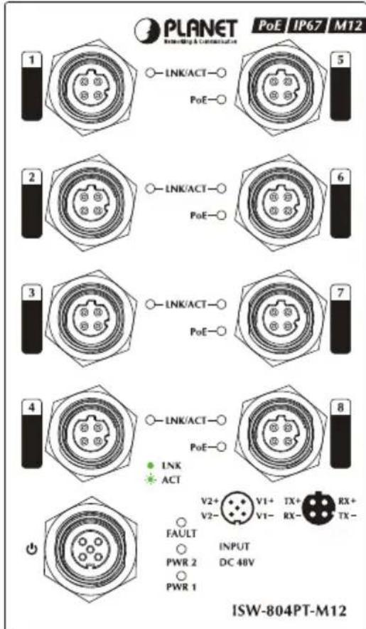
Figure 2-2: ISW-804PT-M12 front panel
2.1.3 LED Indicators
ISW-800T-M12
| LED Color Function | ||
| PWR 1 Green | Lit: indicate the power 1 has power. | |
| PWR 2 Green | Lit: indicate the power 2 has power. | |
| FAULT | Green | Lit: indicate the either power 1 or power 2 has no power. |
| LNK / ACT Green | Lit: indicate the Switch is successfully connecting to the network at 10/100Mbps.Blink: indicate that the Switch is actively sending or receiving data over that port.Off: indicate the Switch is not connecting to the network at 10/100Mbps. | |
ISW-804PT-M12
| LED Color Function | ||
| PWR 1 Green | Lit: indicate the power 1 has power. | |
| PWR 2 Green | Lit: indicate the power 2 has power. | |
| FAULT | Green | Lit: indicate the either power 1 or power 2 has no power. |
| LNK / ACT Green | Lit: indicate the Switch is successfully connecting to the network at 10/100Mbps.Blink: indicate that the Switch is actively sending or receiving data over that port.Off: indicate the Switch is not connecting to the network at 10/100Mbps. | |
| PoE In-Use Port 5 to port 8 | Orange | Lit: indicate the Switch port is providing 15.4 Watts PoE power output.Off: indicate the Switch port is not providing 15.4 Watts PoE power output. |
2.1.4 M12 DC Power Cable Pinout
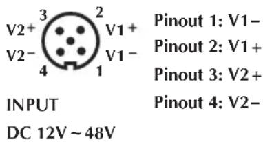
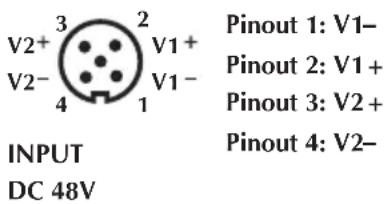
The Industrial M12 Ethernet Switch front panel provides one M12 A-coded 5 pin male connector for DC power input; please use the power cable with M12 A-coded 5 pin female connector from Industrial M12 Ethernet Switch package for DC power input. The Industrial M12 Ethernet Switch power input port pinout is shown as below
ISW-800T-M12
ISW-804PT-M12
Please follow the steps below for DC power cable installation on Industrial M12 Ethernet Switch.
- Plug the DC power cord connector to the power input port of the Industrial M12 Ethernet Switch.
- Screw the nut on DC power cord female connector to the DC power input male connector of Industrial M12 Ethernet Switch and make sure the connection is tight.

Before DC power cord connection, please check and assure your local DC power source is stable.
2.1.5 10/100Mbps Ports with M12 Interface Cable Pinout
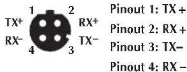
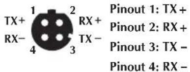
The Industrial M12 Ethernet Switch front panel provides provide eight RJ-45 10/100Mbps ports M12 interfaces, these ports are designed for Ethernet equipments connection. The Industrial M12 Ethernet Switch 10/100Mbps M12 input interface pinout is shown as below
ISW-800T-M12/ISW-804PT-M12
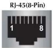
Pinouts for the RJ-45(8-Pin) Port
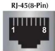
| Pin | Singnal | |
| MDI MDI-X | ||
| 1 | TX+ | RX+ |
| 2 | TX- | RX- |
| 3 | RX+ | TX+ |
| 6 | RX- | TX- |
Please follow the steps below for 10/100Mbps M12 cable installation on Industrial M12 Ethernet Switch.
- Plug the 10/100Mbps M12 cable male connector to the Ethernet female connector input port of the Industrial M12 Ethernet Switch.
- Screw the nut on 10/100Mbps M12 cable male connector to the Ethernet input female connector of Industrial M12 Ethernet Switch and make sure the connection is tight.

Due to per Ethernet port of Industrial M12 Ethernet Switch is running at auto negotiation mode. Please assure the opposite Ethernet devices Ethernet ports are running at auto negotiation mode also, otherwise, the Ethernet performance will be poor.
2.2 Mounting Installation
This section describes how to install the Industrial M12 Ethernet Switch and make connections to it. Please read the following topics and perform the procedures in the order being presented.
2.2.1 DIN-Rail Mounting
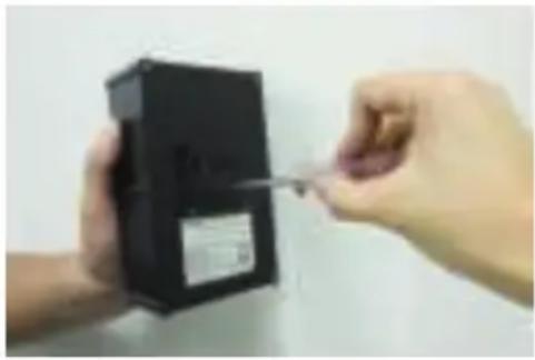
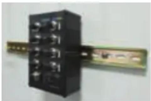
The DIN-Rail is screwed on the Industrial M12 Ethernet Switch when out of factory. When need to replace the wall mount application with DIN-Rail application on Industrial M12 Ethernet Switch, please refer to following figures to screw the DIN-Rail on the Industrial M12 Ethernet Switch. To hang the Industrial M12 Ethernet Switch, follow the below steps:
natural_image
Close-up of hands holding a black electronic device with a screwdriver inserted (no visible text or symbols)Step 1: Screw the DIN-Rail on the Industrial M12 Ethernet Switch.
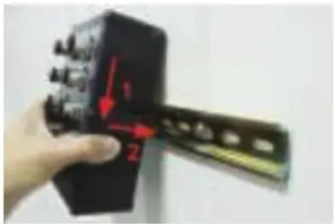
Step 2: Lightly press the button of DIN-Rail into the track.
natural_image
Close-up of a black industrial electrical switch component with multiple ports and a metallic bracket (no visible text or symbols)Step 3: Check the DIN-Rail is tightly on the track.
Step 4: Please refer to following procedures to remove the Industrial M12 Ethernet Switch from the track.

Step 5: Lightly press the button of DIN-Rail for remove it from the track.
2.2.2 Wall Mount Plate Mounting
To install the Industrial M12 Ethernet Switch on the wall, please follows the instructions described below.
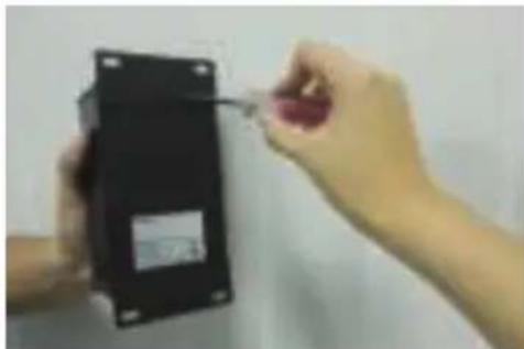
Step 1: Remove the DIN-Rail from the Industrial M12 Ethernet Switch; loose the screws to remove the DIN-Rail.
Step 2: Place the wall mount plate on the rear panel of the Industrial M12 Ethernet Switch.
natural_image
Close-up of hands holding a black electrical component with a tool, no visible text or symbolsStep 3: Use the screws to screw the wall mount plate on the Industrial M12 Ethernet Switch.
Step 4: Use the hook holes at the corners of the wall mount plate to hang the Industrial M12 Ethernet Switch on the wall.
Step 5: To remove the wall mount plate, reverse steps above.
3. Applicaiton
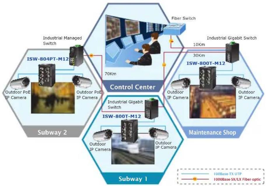
In this paragraph, we will describe how to install Industrial M12 Ethernet Switch and the installation points for the attention.
Public Construction
flowchart
graph TD
    A["Control Center"] --> B["Subway 2"]
    A --> C["Maintenance Shop"]
    A --> D["Subway 1"]
    A --> E["Industrial Managed Switch"]
    A --> F["Industrial Gigabit Switch"]
    A --> G["Industrial IP Camera"]
    A --> H["Outdoor PoE IP Camera"]
    A --> I["Fiber Switch"]
    A --> J["70Km"]
    A --> K["30Km"]
    A --> L["10Km"]
    A --> M["I00Base TX UTP"]
    A --> N["I000Base SX/LX Fiber-optic"]
Public Transmission System

flowchart
graph TD
    A["100Base-TX UTP"] --> B["Industrial M12 PoE Ethernet Switch"]
    C["100Base-TX UTP with PoE"] --> B
    B --> D["3G Router"]
    B --> E["NVR"]
    B --> F["IP Camera"]
    B --> G["IP Camera"]
    B --> H["IP Camera"]
    style A fill:#f9f,stroke:#333
    style C fill:#f9f,stroke:#333
    style B fill:#ccf,stroke:#333
    style D fill:#cff,stroke:#333
    style E fill:#cff,stroke:#333
    style F fill:#cff,stroke:#333
    style G fill:#cff,stroke:#333
    style H fill:#cff,stroke:#333
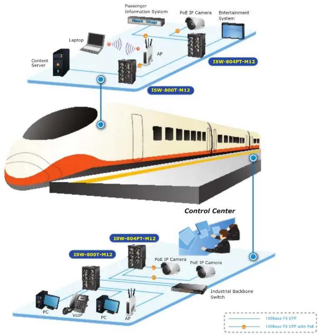
Railway Transmission System
flowchart
graph TD
    subgraph_ISW-804PT-M12["ISW-804PT-M12"]
        A["Content Server"] --> B["Laptop"]
        B --> C["Next Stop"]
        C --> D["AP"]
        D --> E["Passenger Information System"]
        E --> F["PoE IP Camera"]
        F --> G["Entertainment System"]
    end

    subgraph_ISW-800T-M12["ISW-800T-M12"]
        H["Control Center"] --> I["PC"]
        H --> J["VoIP"]
        H --> K["PC"]
        H --> L["AP"]
        I --> M["PoE IP Camera"]
        J --> N["PoE IP Camera"]
        K --> O["Industrial Backbone Switch"]
    end

    style ISW-804PT-M12 fill:#f9f9f9,stroke:#333
    style ISW-800T-M12 fill:#f9f9f9,stroke:#333
    style Control Center fill:#f9f9f9,stroke:#333
Installation Steps
Step 1: Unpack the Industrial M12 Ethernet Switch.
Step 2: Check the DIN-Rail is screwed on the Industrial M12 Ethernet Switch. (Please refer to DIN-Rail Mounting section for DIN-Rail installation If the DIN-Rail is not screwed on the Industrial switch). If you want to wall mount the Industrial M12 Ethernet Switch, then please refer to Wall Mount Plate Mounting section for wall mount plate installation.
Step 3: To hang the Industrial M12 Ethernet Switch on the DIN-Rail track or wall, please refer to the Mounting Installation section.
Step 4: Power on the Industrial M12 Ethernet Switch. (Please refer to the M12 DC Power Cable Inputs) The power LED on the Industrial M12 Ethernet Switch will light up. Please refer to the LED Indicators section for meaning of LED lights.
Step 5: Prepare the twisted-pair, straight through Category 3, 4, 5, 5e, 6 cables for Ethernet connection.
Step 6: Insert one side of Category 3, 4, 5, 5e, 6 cables into the Industrial M12 Ethernet Switch Ethernet port (RJ-45 port) and another side of Category 3, 4, 5, 5e, 6 cables to the network devices' Ethernet port (RJ-45 port), ex: switch, PC or Server. The UTP port (RJ-45) LED on the Industrial M12 Ethernet Switch will light up when the cable connected with the network device. Please refer to the LED Indicators section for LED light meaning.
Step 7: When all connections are all set and LED lights all show in normal, the installation is complete.

Be sure the connected network devices support MDI/MDI-X. If it does not support then use the crossover Category 3, 4, 5, 5e, 6 cables.
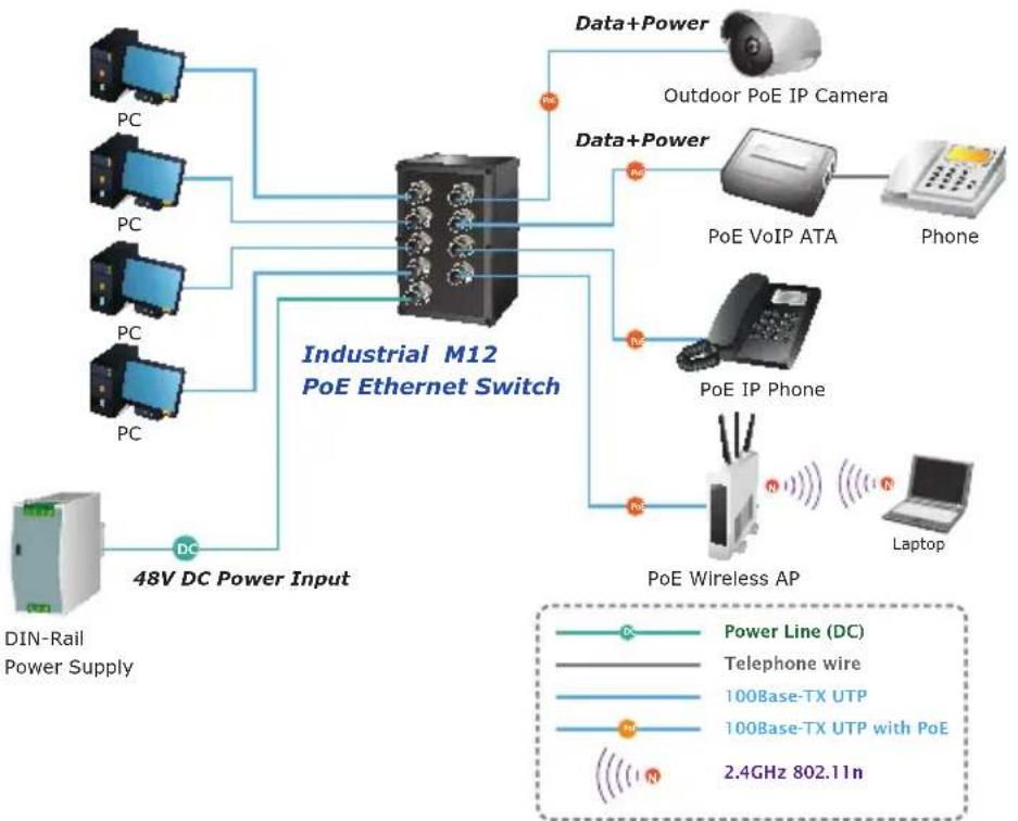
Department/ Workgroup PoE Switch (ISW-804PT-M12 only)
Providing 4-Port PoE in-line power interface, the ISW-804PT-M12 can easily build a power centrally-controlled IP phone system, IP Camera system and Wireless AP group for the enterprise. For instance, up to 4 cameras can be installed around the corner in the company for surveillance demands or up to 4 Wireless AP to build a wireless roaming environment in the office. Without the power-socket limitation, the Switch makes the installation of cameras or Wireless AP more easily and efficiently.
flowchart
graph TD
    A["PC"] --> B["Industrial M12 PoE Ethernet Switch"]
    C["PC"] --> B
    D["PC"] --> B
    E["PC"] --> B
    F["DIN-Rail Power Supply"] --> G["48V DC Power Input"]
    H["Data+Power"] --> I["Outdoor PoE IP Camera"]
    J["Data+Power"] --> K["PoE VoIP ATA"]
    L["PoE Wireless AP"] --> M["Laptop"]
    N["Phone"] --> O["Phone"]
    P["100Base-TX UTP"] --> Q["100Base-TX UTP with PoE"]
    R["2.4GHz 802.11n"] --> S["Ground"]
    T["Power Line (DC)"] --> U["Line"]
    V["Telephone wire"] --> W["Line"]
    X["100Base-TX UTP"] --> Y["Line"]
    Z["100Base-TX UTP with PoE"] --> AA["Line"]
Power over Ethernet Powered Device
 3~5 Watts 3~5 Watts | Voice over IP phonesEnterprise can install POE VoIP Phone, ATA and other Ethernet/non-Ethernet end-devices to the central where UPS is installed for un-interrupt power system and power control system. |
 6~12 Watts 6~12 Watts | Wireless LAN Access PointsMuseum, Sightseeing, Airport, Hotel, Campus, Factory, Warehouse can install the Access Point any where with no hesitation. |
 10~12 Watts 10~12 Watts | IP SurveillanceEnterprise, Museum, Campus, Hospital, Bank, can install IP Camera without limits of install location – no need electrician to install AC sockets. |
 3~12 Watts 3~12 Watts | PoE SplitterPoE Splitter split the PoE 48V DC over the Ethernet cable into 5/12V DC power output. It frees the device deployment from restrictions due to power outlet locations, which eliminate the costs for additional AC wiring and reduces the installation time. |
4. Power Over Ethernet Overview
What is PoE?
Based on the global standard IEEE 802.3af, PoE is a technology for wired Ethernet, the most widely installed local area network technology adopted today. PoE allows the electrical power necessary for the operation of each end-device to be carried by data cables rather than by separate power cords. New network applications, such as IP Cameras, VoIP Phones, and Wireless Networking, can help enterprises improve productivity. It minimizes wires that must be used to install the network for offering lower cost, and less power failures.
IEEE 802.3af also called Data Terminal equipment (DTE) power via Media dependent interface (MDI) is an international standard to define the transmission for power over Ethernet. The 802.3af is delivering 48V power over RJ-45 wiring. Besides 802.3af also define two types of source equipment: Mid-Span and End-Span.
Mid-Span
Mid-Span device is placed between legacy switch and the powered device. Mid-Span is tap the unused wire pairs 4/5 and 7/8 to carry power, the other four is for data transmit.
End-Span
End-Span device is direct connecting with power device. End-Span could also tap the wire 1/2 and 3/6.
PoE System Architecture
The specification of PoE typically requires two devices: the Powered Source Equipment (PSE) and the Powered Device (PD). The PSE is either an End-Span or a Mid-Span, while the PD is a PoE-enabled terminal, such as IP Phones, Wireless LAN, etc. Power can be delivered over data pairs or spare pairs of standard CAT-5 cabling.
How Power is Transferred Through the Cable
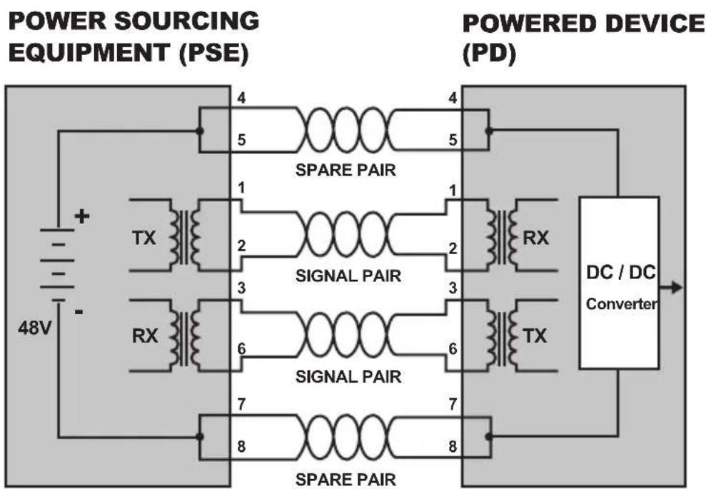
A standard CAT5 Ethernet cable has four twisted pairs, but only two of these are used for 10BASE-T and 100BASE-T. The specification allows two options for using these cables for power, shown in Figure 2 and Figure 3:
The spare pairs are used. Figure 2 shows the pair on pins 4 and 5 connected together and forming the positive supply, and the pair on pins 7 and 8 connected and forming the negative supply. (In fact, a late change to the spec allows either polarity to be used).
flowchart
graph TD
    A["48V Power Source"] --> B["SPARE PAIR"]
    B --> C["4"]
    B --> D["5"]
    B --> E["4"]
    F["POWER SOURCEING EQUIPMENT (PSE)"] --> G["SPARE PAIR"]
    G --> H["1"]
    G --> I["2"]
    G --> J["3"]
    G --> K["6"]
    G --> L["7"]
    G --> M["8"]
    N["POWERED DEVICE (PD)"] --> O["SPARE PAIR"]
    O --> P["1"]
    O --> Q["2"]
    O --> R["3"]
    O --> S["6"]
    O --> T["7"]
    O --> U["8"]
    V["DC / DC Converter"] --> W["Converter"]
Figure 1 - Power Supplied over the Spare Pins
The data pairs are used. Since Ethernet pairs are transformer coupled at each end, it is possible to apply DC power to the center tap of the isolation transformer without upsetting the data transfer. In this mode of operation the pair on pins 3 and 6 and the pair on pins 1 and 2 can be of either polarity.
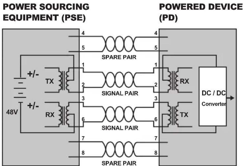
Figure 2 - Power Supplied over the Data Pins
When to install PoE?
Consider the following scenarios:
- You're planning to install the latest VoIP Phone system to minimize cabling building costs when your company moves into new offices next month.
- The company staff has been clamoring for a wireless access point in the picnic area behind the building so they can work on their laptops through lunch, but the cost of electrical power to the outside is not affordable.
- Management asks for IP Surveillance Cameras and business access systems throughout the facility, but they would rather avoid another electrician's payment.
References:
IEEE Std 802.3af-2003 (Amendment to IEEE Std 802.3-2002, including IEEE Std 802.3ae-2002), 2003 Page(s):0_1-121
White Paper on Power over Ethernet (IEEE 802.3af) http://www.poweroverethernet.com/articles.php?article_id=52
Microsemi /PowerDsine http://www.microsemi.com/PowerDsine/
Linear Tech http://www.linear.com/
5. Troubleshooting
This chapter contains information to help you solve issues. If the Industrial M12 Ethernet Switch is not functioning properly, make sure the Industrial M12 Ethernet Switch was set up according to instructions in this manual.
The per port LED is not lit
Solution:
Check the cable connection of the Industrial M12 Ethernet Switch.
Performance is bad
Solution:
Check the speed duplex mode of the partner device. The Industrial M12 Ethernet Switch is run at Auto-negotiation mode and if the partner is set to half duplex, then the performance will be poor.
Per port LED is lit, but the traffic is irregular
Solution:
Check that the attached device is not set to dedicate full duplex. Some devices use a physical or software switch to change duplex modes. Auto-negotiation may not recognize this type of full-duplex setting.
Why the Industrial M12 Ethernet Switch doesn't connect to the network
Solution:
Check per port LED on the Industrial M12 Ethernet Switch. Try another port on the Industrial M12 Ethernet Switch Make sure the cable is installed properly Make sure the cable is the right type Turn off the power. After a while, turn on power again.
Appendix A: Networking Connection
A.1 Switch's RJ-45 Pin Assignments
10/100Mbps, 10/100Base-TX
| RJ-45 Connector pin assignment | ||
| Contact | MDI Media Dependant Interface | MDI-X Media Dependant Interface -Cross |
| 1 Tx + | (transmit) Rx + (receive) | |
| 2 Tx - | (transmit) Rx - (receive) | |
| 3 Rx + | (receive) Tx + (transmit) | |
| 4, 5 Not used | ||
| 6 Rx - | (receive) Tx - (transmit) | |
| 7, 8 Not used | ||
A.2 RJ-45 Cable Pin Assignments
ISW-800T-M12/ISW-804PT-M12
Pinouts for the RJ-45(8-Pin) Port
| Pin | Singnal | |
| MDI MDI-X | ||
| 1 | TX+ | RX+ |
| 2 | TX- | RX- |
| 3 | RX+ | TX+ |
| 6 | RX- | TX- |
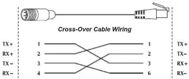
M12(4-Pin, M) to RJ-45(8-Pin) Cross-Over Cable Wiring
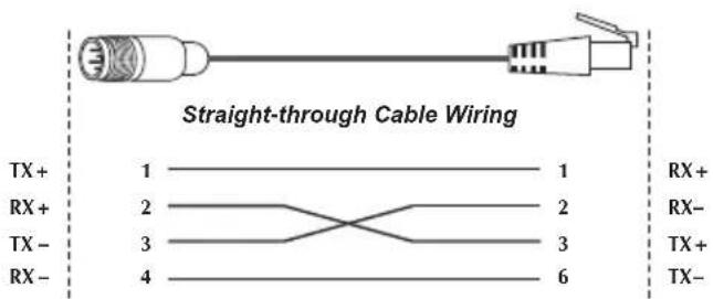
M12(4-Pin, M) to RJ-45(8-Pin) Straight-Trough Cable Wiring
The standard RJ-45 receptacle/connector
There are 8 wires on a standard UTP/STP cable and each wire is color-coded. The following shows the pin allocation and color of straight cable and crossover cable connection:
| Straight Cable | SIDE 1 | SIDE 2 | |
| 1 2 3 4 5 6 7 8 1 2 3 4 5 6 7 8 | SIDE 1 | 1 = White/Orange 2 = Orange 3 = White/Green 4 = Blue 5 = White/Blue | 1 = White/Orange 2 = Orange 3 = White/Green 4 = Blue 5 = White/Blue |
| SIDE 2 | 6 = Green 7 = White/Brown 8 = Brown | 6 = Green 7 = White/Brown 8 = Brown | |
| Straight Cable | SIDE 1 SIDE 2 | ||
| 1 2 3 4 5 6 7 8 1 2 3 4 5 6 7 8 | SIDE 1 | 1 = White/Orange 2 = Orange 3 = White/Green 4 = Blue 5 = White/Blue | 1 = White/Green 2 = Green 3 = White/Orange 4 = Blue 5 = White/Blue |
| SIDE 2 | 6 = Green 7 = White/Brown 8 = Brown | 6 = Orange 7 = White/Brown 8 = Brown | |
Figure A-1: Straight-Through and Crossover Cable
Please make sure your connected cables are with same pin assignment and color as above picture before deploying the cables into your network.
This page is intentionally left blank
- Industrial IP67 Rated 8-Port 10/100Mbps M12 Ethernet Switch
- Trademarks
- Disclaimer
- FCC Warning
- CE Mark Warning
- WEEE Warning
- Revision
- Table of Contents
- Introduction .... 5
- Installation 12
- Product Description....12
- Mounting Installation 16
- Applicaiton ....18
- Power Over Ethernet Overview ......22
- Troubleshooting ....25
- Appendix A: Networking Connection ....26
- Introduction
- Package Contents
- How to Use This Manual
- This Industrial M12 Ethernet Switch User Manual is structured as follows:
- Chapter 2 Installation
- Chapter 3 Application
- Chapter 4 Power over Ethernet overview (ISW-804PT-M12 only)
- Chapter 5 Troubleshooting
- Appendix A
- Product Features
- Physical Port
- Layer 2 Features
- Industrial Case / Installation
- Physical Dimension
- Installation
- Product Description
- Product Overview
- Switch Front Panel
- LED Indicators
- ISW-800T-M12
- ISW-804PT-M12
- M12 DC Power Cable Pinout
- 10/100Mbps Ports with M12 Interface Cable Pinout
- ISW-800T-M12/ISW-804PT-M12
- Pinouts for the RJ-45(8-Pin) Port
- Mounting Installation
- DIN-Rail Mounting
- Wall Mount Plate Mounting
- Applicaiton
- Installation Steps
- Department/ Workgroup PoE Switch (ISW-804PT-M12 only)
- Power Over Ethernet Overview
- What is PoE?
- Mid-Span
- End-Span
- PoE System Architecture
- How Power is Transferred Through the Cable
- When to install PoE?
- References:
- Troubleshooting
- The per port LED is not lit
- Performance is bad
- Per port LED is lit, but the traffic is irregular
- Why the Industrial M12 Ethernet Switch doesn't connect to the network
- Appendix A: Networking Connection
- A.1 Switch's RJ-45 Pin Assignments
- A.2 RJ-45 Cable Pin Assignments
- The standard RJ-45 receptacle/connector
Brand : Planet
Model : ISW-804PT-M12
Category : Switch