GS-2328 - Switch LANCOM - Free user manual and instructions
Find the device manual for free GS-2328 LANCOM in PDF.


User questions about GS-2328 LANCOM
0 question about this device. Answer the ones you know or ask your own.
Ask a new question about this device
Download the instructions for your Switch in PDF format for free! Find your manual GS-2328 - LANCOM and take your electronic device back in hand. On this page are published all the documents necessary for the use of your device. GS-2328 by LANCOM.
USER MANUAL GS-2328 LANCOM
© 2017 LANCOM Systems GmbH, Würselen (Germany). All rights reserved.
While the information in this manual has been compiled with great care, it may not be deemed an assurance of product characteristics. LANCOM Systems shall be liable only to the degree specified in the terms of sale and delivery.
The reproduction and distribution of the documentation and software supplied with this product and the use of its contents is subject to written authorization from LANCOM Systems. We reserve the right to make any alterations that arise as the result of technical development.
Windows® and Microsoft® are registered trademarks of Microsoft, Corp.
The LANCOM Systems logo, LCOS and the name LANCOM are registered trademarks of LANCOM Systems GmbH. All other names or descriptions used may be trademarks or registered trademarks of their owners.
Subject to change without notice. No liability for technical errors or omissions.
Products from LANCOM Systems include software developed by the OpenSSL Project for use in the OpenSSL Toolkit (http://www.openssl.org/).
Products from LANCOM Systems include cryptographic software written by Eric Young (eay@cryptsoft.com).
Products from LANCOM Systems include software developed by the NetBSD Foundation, Inc. and its contributors.
Products from LANCOM Systems contain the LZMA SDK developed by Igor Pavlov.
LANCOM Systems GmbH
Adenauerstr. 20/B2
52146 Würselen
Germany
www.lancom.com
Würselen, February 2017
natural_image
Two technical diagrams showing a mechanical component and a device with a close-up view (no text or symbols)Kapitel 3: Installation
natural_image
Technical diagram showing two mechanical assembly components with mounting holes and red alignment markers (no text or symbols)
text_image
LANCDM GS-2326P+ System Information Basic System: LANCDM System Performance: System performance Cyberics: System performance System Data: System data System City: System city System Location: System location System Network: System network System Server: System server System Hardware: System hardware System Number: System number System Address: System address System Address Name: System address System Address Type: System type System Address Address Address Address Address Address Address Address Address Address Address Address Address Address Address Address Address Address Address Address Address Address Address Address Address Address Address Address Address Address Address Address Address Address Address Address Address Address Address Address Address Address Address Address Address Address Address Address Address Address Address Address Address Address Address Address Address Address Address Address Address Address Address Address Address Address Address Address Address Address Address Address Address Address Address Address Address Address Address Address Address Address Address Address Address Address Address Address Address Address Address Address Address Address Address Address Address Address Address Address address address address address address address address address address address address address address address address address address address address address address address address address address address address address address address address address address address address address address address address address address address address address address address address address address address address address address address address address address address address address address address address address address address address address address address address address address address address address address address address address address address address address address address address address address address address address address address address address address address address address addresses System Number: System number System Address: System address System Address Name: System address name System Address Type: System address type System Address Address: System address Address Address Address Address Address Address Address Address Address Address Address Address Address Address Address Address Address Address Address Address Address Address Address Address Address Address Address Address Address Address Address Address Address Address Address Address Address AddressAddressAddressAddressAddressAddressAddressAddressAddressAddressAddressAddressAddressAddressAddressAddressAddressAddressAddressAddressAddressAddressAddressAddressAddressAddressAddressAddressAddressAddressAddressAddressAddressAddressAddressAddressAddressAddressAddressAddressAddressAddressAddressAddressAddressAddressAddressAddressAddressAddressAddressAddressAddressAddressAddressAddressAddressAddressAddressAddressAddressAddressAddressAddressAddressAddressAddressAddressAddressAddressAddressAddressAddressAddressAddressAddressAddressAddressAddressAddressAddressAddressAddressAddressAddressAddressAddressAddressAddressAddressAddressAddressAddressAddressAddressAddressAddressAddressAddressAddressAddressAccess地址: http://www.hk.com/ http://www.hk.com/ http://www.hk.com/ http://www.hk.com/ http://www.hk.com/ http://www.hk.com/ http://www.hk.com/ http://www.hk.com/ http://www.hk.com/ http://www.hk.com/ http://www.hk.com/ http://www.hk.com/ http://www.hk.com/ http://www.hk.com/ http://www.hk.com/ http://wks.com/ http://wks.com/ http://wks.com/ http://wks.com/ http://wks.com/ http://wks.com/ http://wks.com/ http://wks.com/ http://wks.com/ http://wks.com/ http://wks.com/ http://wks.com/ http://wks.com/ http://wks.com/ http://wks.com/ http://wks.com/ http://wks.com/ http:/wks.com/ http://wks.com/ http://wks.com/ http://wks.com/ http://wks.com/ http://wks.com/ http://wks.com/ http://wks.com/ http://wks.com/ http://wks.com/ http://wks.com/ http://wks.com/ http://wks.com/ http://wks.com/ http://wks.com/ http://wks.com/ http://wks.com/LANCOM switches are the foundation for a reliable infrastructure. These switches deliver multiple intelligent features for improving the availability of your critical business applications, protecting your sensitive information, and optimizing your network bandwidth to deliver information and applications more effectively. Easy to set up and use, they provide the ideal combination of economic efficiency and technical capabilities from entry level to enterprise level networks. All models offer enhanced security and management functions. In addition, they have networking features to support common applications of data, voice, security and wireless networking.
1.2 Switch Architecture
The switches performs a wire-speed, non-blocking switching fabric. This allows wire-speed transport of multiple packets at low latency on all ports simultaneously. The switch also features full-duplex capability on all ports, which effectively doubles the bandwidth of each connection.
The switches use store-and-forward technology to ensure maximum data integrity. With this technology, the entire packet must be received into a buffer and checked for validity before being forwarded. This prevents errors from being propagated throughout the network.
1.3 Network Management
The switch can be managed over the network with a web browser or CLI (Command Line Interface) via SSH or Telnet. Particular devices can be configured via the web-based interface only. These switches include a built-in network management agent that allows it to be managed in-band using SNMP or RMON (Groups 1, 2, 3, 9) protocols.
For out-band management particular devices offer a RJ45 console port connector on the front panel, other devices offer a serial port on the back or front.

For a detailed description of the management features, refer to the user manual.
2 Network Planning
2.1 Introduction to Switching
A switch allows simultaneous transmission of multiple packets, it can partition a network more efficiently than bridges or routers. Therefore, the switch has been recognized as one of the most important device for today's networking technology.
When performance bottlenecks are caused by congestion at the network access point such as file server, the device can be connected directly to a switched port. And, by using full-duplex mode, the bandwidth of the dedicated segment can be doubled to maximize throughput.
When networks are based on repeater (hub) technology, the distance between end stations is limited by a maximum hop count. However, a switch can subdivide the network into smaller and better manageable segments and recombine them to larger networks, thus removing the limitations by the maximum hop count.
A switch can be easily configured in any Ethernet, Fast Ethernet, or Gigabit Ethernet network to significantly increase bandwidth while using conventional cabling and network cards.
2.2 Application Examples
The switches implement Gigabit Ethernet TP ports with auto MDIX and slots for removable SFP modules which support comprehensive types of fiber connection, such as LC and BiDi-LC modules. It is not only designed to segment your network, but also to provide a wide range of options in setting up network connections. Some typical applications are described below.
Among others, the switches are suitable for the following applications:
Remote site application is used in Enterprise or SMB
Peer-to-peer application is used in two remote offices
Office network
Chapter 3: Installation
3 Installation
3.1 Selecting a Site
The switch can be mounted in a standard 19-inch equipment rack or on a flat surface. Be sure to follow the guidelines below when choosing a location.
Position the switch near the devices you want to link and near a power outlet.
Be able to maintain the temperature of the switch within the limits listed in the Hardware Quick Reference Guide.
Have the switch accessible for installing, cabling, and maintaining the devices.
Allow the status LEDs to be clearly visible.

Make sure the twisted-pair Ethernet cable is always routed away from power lines, radios, transmitters or any other electrical interference.

Make sure that the switch is connected to a separate grounded power outlet that provides 100 to 240 VAC, 50 to 60 Hz.
3.2 Ethernet Cabling
To ensure proper operation when installing the switch into a network, make sure that the available cables are suitable for 100BASE-TX or 1000BASE-T operation. Check the following criteria against the current installation of your network:
Cable type: Unshielded twisted pair (UTP) or shielded twisted pair (STP) cable with RJ-45 connectors; Category 5 or Category 5e with maximum length of 100 meters is recommend for 100BASE-TX, and Category 5e or 6 with maximum length of 100 meters is recommend for 1000BASE-T
Protection from radio frequency interference emissions
Electrical surge suppression
Separation of electrical wires and data – based network wiring
Safe connections with no damaged cables, connectors or shields
natural_image
Two technical diagrams showing a mechanical component and a cylindrical device (no text or symbols present)Chapter 3: Installation
3.3 Package Content and Accessories
Before beginning with the installation, please check that nothing is missing from your package. Along with the LANCOM switch the box should contain the following accessories:
Power cord
19" adapter (2 pieces) and mounting materials
Serial cable (model dependant)
Printed documentation
Should anything be missing, please take up immediate contact to your dealer or the address on the delivery note supplied with your device.
Ensure that you have all additional accessories at hand w required during installation.

3.4 Mounting and Connecting the LANCOM Switch
Installing the LANCOM switch involves the following steps:
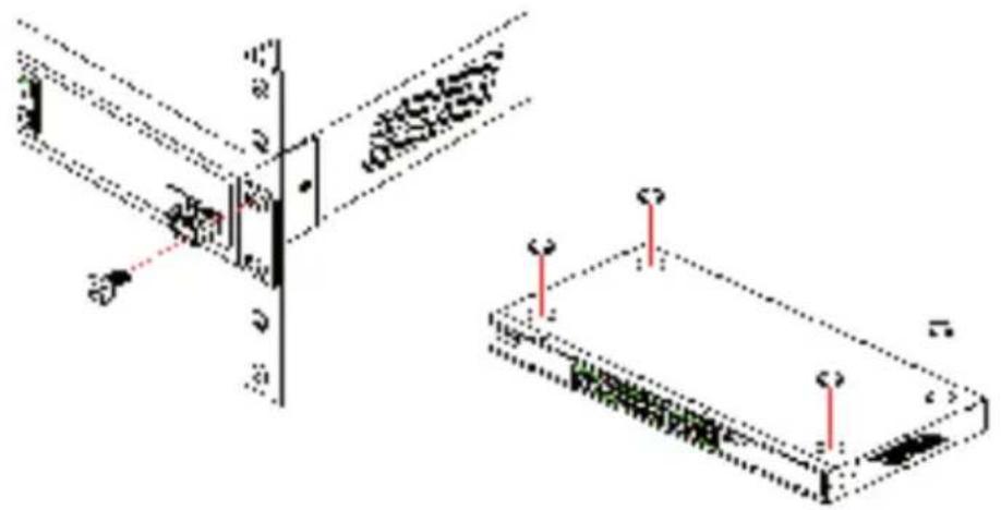
① Mounting – The device is designed for mounting in an available 19" unit in a server cabinet. Make use of the supplied mounting brackets for 19" cabinets. If necessary fix the rubber pads to the underside of the device to prevent any scratching to other equipment.
natural_image
Technical diagram showing two mechanical assembly components with mounting holes and alignment lines (no text or symbols)
Ensure that the device has sufficient ventilation to prevent damage from excessive heat build-up.
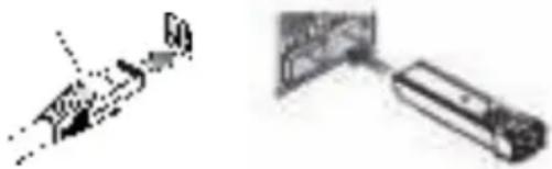
② LAN connection – Connect the network devices to the ports of the LANCOM switch by means of a suitable twisted-pair cable
Chapter 4: Configuring and Monitoring the LANCOM Switch
(TP cable). The connectors automatically detect the available data transfer speeds and the pin assignment (autosensing).


Use only standard TP cables of category CAT 5 or better with a maximum length of 100 m to ensure the best possible data transfer. Cross-over cables can be used thanks to the auto-sensing function.

If optical connections are used, additional modules are necessary which can be purchased as accessories.
③ Supply power – Supply power to the device by means of the IEC power cable and/or an external power supply unit (model dependent).
④ Ready for operation? – After a brief self-test, the power or system LED lights up continuously. Green Link/Act LEDs show which LAN connectors are used for a connection.
4 Configuring and Monitoring the LANCOM Switch
4.1 Configuration options
There are two different options to configure the device:
By means of a graphical user interface or via browser (WEBconfig). This option is only available if you have network access to the device's IP address from your computer. The computer requires an operating system that supports TCP/IP (e.g. Windows, Linux, BSD Unix, Apple Mac OS) and also access to the LAN and a webbrowser.
Text-orientated configuration via console (Command Line Interface – CLI): This method of configuration, which requires a program such as SSH, Telnet, Hyperterminal, or similar, can be conducted over a network connection or with a direct connection via serial interface (RS-232).
When working with Windows, you can use the LANtools to detect and monitor LANCOM switches.
LANconfig is the Windows configuration program for all LANCOM devices. LANconfig searches for all LANCOM devices in your network. You can use this to start the Web-based configuration of a LANCOM switch.
With LANmonitor you can use a Windows computer to monitor all of your LANCOM devices. This program displays all important status information.
4.1.1 Starting WEBconfig
There are two ways of starting the configuration by browser:
If you know the device's IP address, simply enter this into the address line of the browser. The factory settings for accessing the device are: User name "admin", password "admin".
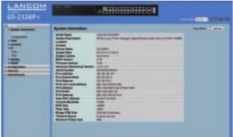
If you do not have the device's IP address, LANconfig can be used to search for it. To start LANconfig click on Start / Programs / LANCOM / LANconfig. LANconfig automatically searches for all available devices in your network. Any available LANCOM routers or access points displayed in the list, including LANCOM switches. Double-click on this entry to start the browser automatically with the correct IP address.
text_image
LANCOM GS-2326P+ System Information System Name: www.ncom.com System Parameters: 20000000000000000000000000000000000000000000000000000000000000000000000000000000000000000000000000000 System Parameters: 25.1.1.1.1.1.1.1.1.1.1.1.1.1.1.1.1.1.1.1.1.1.1.1.1.1.1.1.1.1.1.1.1.1.1.1.1.1.1.1.1.1.1.1.1.1.1.1.1.1.1.2 System Parameters: 25.1.1.1.1.1.1.1.1.1.1.1.1.1.1.1.1.1.1.1.1.1.1.1.1.1.1.1.1.1.1.1.1.1.1.1.1.1.1.1.1.1.1.2 System Parameters: 25.1.2.2.2.2.2.2.2.2.2.2.2.2.2.2.2.2.2.2.2.2.2 System Parameters: 25.2.2.2.2.2.2.2.2.2.2.2.2.2.2.2 System Parameters: 25.3.3.3.3.3.3.3.3.3.3.3.3 System Parameters: 25.4.4.4.4.4.4.4.4.4.4. System Parameters: 25.5.5.5.5.5.5-6 System Parameters: 25-7 System Parameters: 25-8 System Parameters: 25-9 System Parameters: 25-10 System Parameters: 25-11 System Parameters: 25-12 System Parameters: 25-13 System Parameters: 25-14 System Parameters: 25-15 System Parameters: 25-16 System Parameters: 25-17 System Parameters: 25-18 System Parameters: 25-19 System Parameters: 25-20 System Parameters: 25-21 System Parameters: 25-22 System Parameters: 25-23 System Parameters: 25-24 System Parameters: 25-25 System Parameters: 25-26 System Parameters: 25-27 System Parameters: 25-28 System Parameters: 25-29 System Parameters: 25-30 System Parameters: 25-31 System Parameters: 25-32 System Parameters: 25-33 System Parameters: 25-34 System Parameters: 25-35 System Parameters: 25-36 System Parameters: 25-37 System Parameters: 25-38 System Parameters: 25-39 System Parameters: 25-40 System Parameters: 25-41 System Parameters: 25-42 System Parameters: 25-43 System Parameters: 25-44 System Parameters: 25-45 System Parameters: 25-46 System Parameters: 25-47 System Parameters: 25-48 System Parameters: 25-49 System Parameters: 25-50 System Parameters: 25-51 System Parameters: 25-52 System Parameters: 25-53 System Parameters: 25-54 System Parameters: 25-55 System Parameters: 25-56 System Parameters: 25-57 System Parameters: 25-58 System Parameters: 25-59 System Parameters: 25-60 System Parameters: 25-61 System Parameters: 25-62 System Parameters: 25-63 System Parameters: 25-64 System Parameters: 25-65 System Parameters: 25-66 System Parameters: 25-67 System Parameters: 25-68 System Parameters: 25-69 System Parameters: 25-70 System Parameters: 25-71 System Parameters: 25-72 System Parameters: 25-73 System Parameters: 25-74 System Parameters: 25-75 System Parameters: 25-76 System Parameters: 25-77 System Parameters: 25-78 System Parameters: 25-79 System Parameters: 25-80 System Parameters: 25-81 System Parameters: 25-82 System Parameters: 25-83 System Parameters: 25-84 System Parameters: 25-85 System Parameters: 25-86 System Parameters: 25-87 System Parameters: 25-88 System Parameters: 25-89 System Parameters: 25-90 System Parameters: 25-91 System Parameters: 25-92 System Parameters: 25-93 System Parameters: 25-94 System Parameters: 25-95 System Parameters: 25-96 System Parameters: 25-97 System Parameters: 25-98 System Parameters: 25-99 System Parameters: 26-00What is the IP Address of my LANCOM Switch?
The current IP address of the LANCOM switch after being switched on depends on the network constellation.
Networks with DHCP server – In its factory settings, the LANCOM switch is set for auto DHCP mode, meaning that it searches for a DHCP server to assign it an IP address, subnet mask and gateway address. The assigned IP address can only be determined by using the appropriate tools (e.g. LANconfig) or via DHCP server. If the DHCP server is a LANCOM device, the IP address of the LANCOM switch can be read out from the DHCP table. If this is the case, the LANCOM switch can be accessed from any network computer that receives its IP address from the same DHCP server.
Network without a DHCP server – If no DHCP server is present in the network, the LANCOM switch adopts an address which, depending on the model, may be "172.23.56.250" or "172.23.56.251". If this is the case,
Chapter 4: Configuring and Monitoring the LANCOM Switch
the LANCOM switch can be accessed from any network computer with its IP address set to the address range "172.23.56.x".
4.1.2 Starting the Command Line Interface over the Network
If you know the device's IP address (see section above) and the LANCOM switch is accessible from your computer via the network, you can use the command line interface via the network.
① To do this, start a console such as SSH or Telnet and enter the device's IP address as the target.
② Log on with user name and password (default: admin, password: admin).
4.1.3 Starting the Command Line Interface over the Serial Connection
If you do not know the IP address of the device, you can use the command line interface via a serial connection.
① Use the serial configuration cable to connect the LANCOM switch to the configuration computer (see "Mounting and connecting the LANCOM Switch").
② Start a terminal program on the configuration computer, such as PuTTY. Use the following parameters for the connection:
Baud rate: 115200
Stop bits: 1
Data bits: 8
Parity: N
Flow control: none
③ Log on with user name and password (default: admin, password: admin).
4.2 Monitoring the LANCOM Switch with LANmonitor
The current status of the device and all its ports can be monitored using the LEDs on the front panel. With LANmonitor the devices can be observed from any workstation without being able to see the switch. Besides the status information provided by the LEDs, LANmonitor provides further important information on the ports.
4.2.1 Ethernet Port Status
LANmonitor displays the current status of all of the device's Ethernet ports. This includes monitoring the status as configured by the admin (config state) and the actual port status (link state). Each port is displayed with two colored symbols in LANmonitor:
The left icon shows the config status:
Gray: The port is deactivated in the configuration
Yellow: The port is activated in the configuration
The right-hand icon shows the link status:
Gray: No active network device is connected to the port
Green: A network device is connected to the port and active
Apart from the status, LANmonitor displays the VLAN ID for each port and the detected data rate at active ports connected to active network devices.
Service & Support
With your new LANCOM networking product, you are benefiting not only from our many years of experience in the field of data communication, but also from our excellent service. This document contains all of the information you should have ready if you ever need to contact us for product service.
LANCOM Support
User Manual
If you encounter any problems when installing or operating your product, please refer to the manual first.
Internet
Actual support information and the LANCOM Knowledge Base can be obtained from the support pages on our website: www.lancom-systems.com/service-support
Firmware
The latest LCOS firmwares, drivers, tools, and documentation can be downloaded free of charge from the download section on our website: www.lancom-systems.com/downloads
Further Help
If you should need personal assistance, please contact your local reseller.
LANCOM Service
Warranty
All LANCOM Systems products are supplied with a manufacturer warranty.
The warranty period depends on the device type:
2 years for all LANCOM unmanaged and websmart switches and LANCOM AirLancer accessories
3 years for all LANCOM routers, gateways, and access points
5 years for all LANCOM managed switches The LANCOM Systems warranty conditions apply. If you wish to submit a warranty claim, please contact your local reseller.
Warranty Extension
In addition, LANCOM Systems offers the warranty extensions LANCOM Warranty Basic Option and LANCOM Warranty Advanced Option. Additional information can be found on our website:
www.lancom-systems.com/warranty-extension
Your LANCOM Team
Zentrale
LANCOM Systems GmbH
Adenauerstr. 20/B2
52146 Würselen
Deutschland
Telefon
+49 (0)2405 49936 0
Fax
+49 (0)2405 49936 99
info@lancom.de
Internet
www.lancom-systems.de