
SSP 7.1 - Processor Extron - Free user manual and instructions
Find the device manual for free SSP 7.1 Extron in PDF.


| Product Type | 7.1 Channel Surround Sound Processor |
| Channels | 7.1 (Front L/R, Center, Surround L/R, Back L/R, Subwoofer) |
| Digital Audio Inputs | 4 (2 optical TOSLINK, 2 coaxial S/PDIF) |
| Analog Audio Input | 1 balanced/unbalanced stereo or mono (5-pin captive screw) |
| Audio Outputs | Balanced/unbalanced line level for 7.1 speakers (captive screw) |
| Supported Digital Formats | Dolby Digital (2/0, 5.1, Surround EX), DTS (2-channel, Digital Surround, 96/24, ES Matrix, ES Discrete), PCM (up to 96 kHz) |
| Analog Input Gain | 0 dB to +24 dB |
| Volume Control | Front panel rotary encoder, -100 dB to 0 dB, with LED bar |
| Listening Modes | Dolby Pro Logic II/IIx, DTS Neo:6, Downmix, Mono to All, Stereo to All, and more |
| Equalization | 9-band parametric EQ per output channel |
| Speaker Delay | Compensation delay and lip sync offset (0-100 ms per channel) |
| Test Signals | Pink noise, Dolby noise, external source |
| Control Interfaces | Front panel, RS-232 (3-pole captive screw), front panel config port (TRS), SIS commands |
| Power Supply | 100-240 VAC, 50-60 Hz, 5A |
| Mounting Options | Tabletop, rack mount (optional RSU 129/126), under-desk (optional MBU 125) |
| Safety Compliance | FCC Class B, UL guidelines for rack mounting |
| Front Panel Security | Lockout (Executive Mode) to prevent unauthorized changes |
| Maintenance | Disconnect power before cleaning; no user-serviceable parts inside |
| Battery | Lithium battery (replace only with same type) |
| Included Accessories | Rubber feet for tabletop, power cord, setup software CD, manual |
Frequently Asked Questions - SSP 7.1 Extron
User questions about SSP 7.1 Extron
0 question about this device. Answer the ones you know or ask your own.
Ask a new question about this device
Download the instructions for your Processor in PDF format for free! Find your manual SSP 7.1 - Extron and take your electronic device back in hand. On this page are published all the documents necessary for the use of your device. SSP 7.1 by Extron.
USER MANUAL SSP 7.1 Extron
7.1 Channel Surround Sound Processor
Safety Instructions • English

This symbol is intended to alert the user of important operating and maintenance (servicing) instructions in the literature provided with the equipment.

This symbol is intended to alert the user of the presence of uninsulated dangerous voltage within the product enclosure that may present a risk of electric shock.
Caution
Read Instructions • Read and understand all safety and operating instructions before using the equipment. Retain Instructions • The safety instructions should be kept for future reference.
Follow Warnings • Follow all warnings and instructions marked on the equipment or in the user information.
Avoid Attachments • Do not use tools or attachments that are not recommended by the equipment manufacturer because they may be hazardous.
Power sources • This equipment should be operated only from the power source indicated on the product. This equipment is intended to be used with a main power system with a grounded (neutral) conductor. The third (grounding) pin is a safety feature, do not attempt to bypass or disable it.
Power disconnection • To remove power from the equipment safely, remove all power cords from the rear of the equipment, or the desktop power module (if detachable), or from the power source receptacle (wall plug).
Power cord protection • Power cords should be routed so that they are not likely to be stepped on or pinched by items placed upon or against them.
Servicing • Refer all servicing to qualified service personnel. There are no user-serviceable parts inside. To prevent the risk of shock, do not attempt to service this equipment yourself because opening or removing covers may expose you to dangerous voltage or other hazards.
Slots and openings • If the equipment has slots or holes in the enclosure, these are provided to prevent overheating of sensitive components inside. These openings must never be blocked by other objects.
Lithium battery • There is a danger of explosion if battery is incorrectly replaced. Replace it only with the same or equivalent type recommended by the manufacturer. Dispose of used batteries according to the instructions of the manufacturer.
Avertissement
This equipment has been tested and found to comply with the limits for a Class B digital device, pursuant to part 15 of the FCC rules. These limits provide reasonable protection against harmful interference in a residential installation. This equipment generates, uses, and can radiate radio frequency energy and, if not installed and used in accordance with the instructions, may cause harmful interference to radio communications. There is no guarantee that interference will not occur. If this equipment does cause interference to radio or television reception, which can be determined by turning the equipment off and on, you are encouraged to try to correct the interference by one or more of the following measures:
- Reorient or relocate the receiving antenna.
- Increase the separation between the equipment and receiver.
- Connect the equipment into an outlet on a circuit different from that to which the receiver is connected.
- Consult the dealer or an experienced radio/TV technician for help.
NOTES: This unit was tested with shielded I/O cables on the peripheral devices. Shielded cables must be used to ensure compliance with FCC emissions limits. For more information on safety guidelines, regulatory compliances, EMI/EMF compatibility, accessibility, and related topics, see the "Extron Safety and Regulatory Compliance Guide" on the Extron website.
Copyright
© 2012 Extron Electronics. All rights reserved.
Trademarks
All trademarks mentioned in this manual are the properties of their respective owners.
Conventions Used in this Guide
Notifications
DANGER: Danger indicates a situation that will result in death or severe injury. For example: DANGER: Severe Electric Shock. Disconnect power to this furnishing before cleaning.
WARNING: A warning indicates a situation that has the potential to result in death or severe injury. For example: WARNING: May result in Electric Shock. Devices used in this furnishing should be connected to a properly grounded outlet only (see Grounding Instructions in the device manual).
CAUTION: A caution indications a situation that may result in minor injury.
ATTENTION: Attention indicates a situation that may damage or destroy the product or associated equipment. For example: ATTENTION: Potential Damage to Property. The opening in the table should be cut only by licensed and bonded craftspeople. Exercise care to prevent scarring or damaging the furniture.
NOTE: A note draws attention to important information.
TIP: A tip provides a suggestion to make working with the application easier.
Software Commands
Commands are written in the fonts shown here:
^AR Merge Scene,,Op1 scene 1,1 ^B 51 ^W^C [∅1] R∅∅4∅03∅0∅04∅0∅08∅0∅06∅0 [∅2] 35 [17] [∅3]
Esc X1 * X17 * X20 * X23 * X21 CE ←
NOTE: For commands and examples of computer or device responses mentioned in this guide, the character "∅" is used for the number zero and "0" represents the capital letter "0."
Computer responses and directory paths that do not have variables are written in the font shown here:
Reply from 208.132.180.48: bytes=32 times=2ms TTL=32 C:\Program Files\Extron
Variables are written in slanted form as shown here:
ping xxx.xxx.xxx.xxx -t SOH R Data STX Command ETB ETX
Selectable items, such as menu names, menu options, buttons, tabs, and field names are written in the font shown here:
From the File menu, select New.
Click the OK button.
Contents
Introduction.... 1
About the SSP 7.1....1
SSP 7.1 Features ...... 2
Features......4
Rear Panel Features....4
Front Panel Features and Operation 6
Source Format....6
Mode Override Selection....7
Input Selection....9
Mute Output 10
Complete System Reset....10
Volume Adjustment 11
Analog Input Gain Adjustment....11
Front Panel Security Lockout (Executive Mode) 12
Setup 13
Speaker Setup.... 13
Abbreviations....14
Bass Management 15
Speaker Size Settings 15
Speaker Delay Settings....17
Test Signals 17
Output Channel Trim Settings 17
Listening Mode Settings....18
Dolby Pro Logic II or Ilx Music....18
DTS Neo:6 Music or Cinema 18
Dynamic Range Compression Control 19
Tone Controls 20
Volume Output....21
Equalization....21
Setup and Control Software.... 22
Installing the SSP 7.1 Setup and Control Software 22
Live and Emulate Modes 23
Running the SSP 7.1 Setup and Control Software 24
"Connect to device?" Dialog Box....24
Main Tab....26
Speaker Setup Tab 30
Speaker Configuration Tab 30
Speaker Delay Tab 32
Testing & Output Trim Tab 36
Speaker Equalization Tab....41
Listening Mode Setup Tab 45
Preferences Tab 45
Override Preferences Tab 48
Dolby, DTS and Mono Settings Tab 49
Drop-down Menus....51
SSP 7.1 Setup and Control Software Help File ... 55
Firmware Updates....56
Specifications, Parts, and Accessories .... 58
Specifications....58
Included Parts 60
Optional Accessories 60
Reference Material 61
Source Formats....61
Surround Channel Information......61
Dolby Digital Source Formats (DD) 63
DTS Source Formats (DTS) 64
PCM Digital Source Format (PCM)....65
2-Channel Source Format (2CH)......65
Sampling Frequency 65
Listening Mode Options and Usage......66
Listening Mode Options 66
Listening Modes Usage 70
Listening Mode and Output Channels......73
Source Formats and Listening Modes with
Different Speaker Setups....75
SIS Commands 78
Introduction to SIS 78
Symbols Used in this Manual.... 79
Error Messages 84
Expected Unsolicited Responses 84
Command and Response Table for
SIS Commands 85
Setting Speaker Delay Settings Using
SIS Commands 94
Two Person Setup 94
Setup with a Real Time Analyzer (RTA)
Calibration Tool....95
Setting up Test Sources with SIS Commands.. 96
Mounting 97
Tabletop Placement....97
Rack Mounting 97
UL Guidelines for Rack Mounting....97
Rack Mounting Procedure 98
Under-desk Mounting....98
Glossary 99
Index 102
Introduction
This manual contains information on how to mount, install, and configure the Extron® SSP 7.1 surround sound processor.
Unless otherwise specified, references in this manual to the SSP 7.1, "sound processor," or "surround sound processor" all refer to the SSP 7.1 unit.
About the SSP 7.1
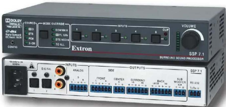
The SSP 7.1 is a 7.1 channel surround sound processor with four digital inputs and one analog input. A variety of selectable listening modes can be changed to match the source format.
The unit can accept 2 channel analog signals, as well as digital pulse code modulation (PCM) signals, and output them through various matrix decoding mode options for use in 5.1 to 7.1 system configurations.
The SSP 7.1 can decode and process licensed, branded digital source formats from Dolby® Digital ^1 and DTS ^2 , in their originally encoded formats. These include:
• Dolby Digital 2/0
• Dolby Digital 2/0 Surround
• Dolby Digital 5.1
• Dolby Digital Surround EX ^™1
• DTS 2-channel
• DTS Digital Surround ^2
• DTS 96/24 ^2
• DTS-ES ^2 Matrix 6.1
• DTS 96/24 ES Matrix 6.1
• DTS-ES Discrete 6.1
SSP 7.1 Features
Advanced control and configuration — The SSP 7.1 Setup and Control Software provides additional configuration options beyond those available through front panel control.
Emulate and Live modes for configuration — The control program can be used in Emulate mode to create an SSP 7.1 configuration. The modifications can be saved and applied to the unit when a connection is established. In Live mode, the changes are made directly to the unit.
Four digital audio inputs — The unit accepts four digital inputs through two optical (TOSLINK®) digital inputs and two S/PDIF coaxial (RCA) digital inputs.
One analog input — The unit accepts one balanced/unbalanced analog input on a 5-pole captive screw connector.
Configurable analog input — Input 5 accepts balanced or unbalanced stereo analog inputs and can be configured to accept one or two balanced or unbalanced mono inputs through a captive screw connector. The mono source can be left, right, or a mix summed of the two.
Automatic surround sound format detection and decoding — The SSP 7.1
automatically detects the format of the incoming audio signal, and then applies the user-defined decoding so that signals are sent to the appropriate outputs.
Input source surround sound format indicator — The appropriate LED indicator illuminates to indicate the incoming format of the selected input source, whether Dolby Digital, DTS, PCM, or two-channel analog.
Dolby Digital and DTS playback — The unit is able to decode and process source format from Dolby Digital and DTS, in their originally encoded formats.
Matrix decoding — The surround sound processor can decode stereo signals to produce multichannel output.
Downmix multichannel source formats — Downmixing produces a mixed stereo or mono channel with an additional option to redistribute the downmixed signal to all channels.
Front panel audio level adjustment with LED level and analog clip indication —
Provides overall output volume adjustment for all outputs as well as adjustment of input level for the analog input. Accompanying LEDs display input gain level, and a dedicated LED indicator illuminates red when analog clipping has occurred.
Multiple listening modes — Not all listening modes are compatible with certain input signals. The listening mode depends not only on the format of the source material but also on the speaker configuration of the setting. Only those listening modes that are compatible for a given input are available for that signal. The SSP 7.1 comes with factory default listening modes that have been matched to the source format to take into account source format and speaker configuration.
Listening mode override — Listening mode override customizes the listening mode to the needs of the source format, speaker configuration, the venue, and the personal preferences of the listener. Selections made through the front panel can be further refined by the SSP 7.1 Setup and Control Software.
This feature can be used to associate a specific listening mode with each input type, allowing the user to switch quickly to the listening mode that suits each input type for a given room configuration and the individual user preferences.
Test signals for setup and calibration — The SSP 7.1 generates test signals, including band-limited Dolby noise and full-bandwidth pink noise, to facilitate calibration of sound pressure levels from all speakers, and to fine-tune the interaction of a speaker with the acoustical environment. The SSP 7.1 also offers the option to use an external source for test signals, which can then be directed to any speaker, or all speakers in sequence.
Speaker compensation delay — The signal to each output channel can be individually delayed so that the sound from all speakers is synchronized when it reaches the listener.
Lip sync offset — This feature delays an audio signal so that it is resynchronized with a video signal that has been delayed by video processing. The offset can be applied to each input channel independently.
Equalization — Nine bands of parametric EQ are available to enhance tone, compensate for differences in individual speaker output, and adjust frequency response for a given acoustic environment.
Features
The next two sub-sections describe the features and operation of the SSP 7.1.
• Rear Panel Features
• Front Panel Features and Operation
Rear Panel Features
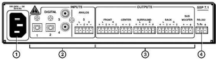
Figure 1. SSP 7.1 Rear Panel Features
NOTE: On earlier models of the SSP 7.1, the Surround Output Channels are labeled Side.
① AC power input — Use an IEC power cable to connect the processor to a 100 - 240 VAC, 50 - 60 Hz, power source.
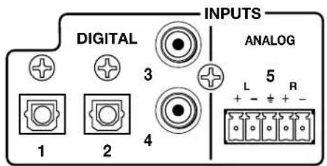
② Audio inputs — The SSP 7.1 accepts four digital inputs and one analog input.
- Inputs 1 and 2 accept digital signals through S/PDIF optical cables.
- Inputs 3 and 4 accept digital signals through S/PDIF coaxial cables.
- Input 5 accepts a balanced or unbalanced, stereo or mono, analog input through a 5-pin captive screw connector.
The following diagram shows the correct wiring for different analog input signals.
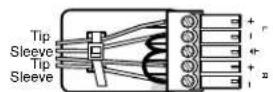
Unbalanced Stereo Input
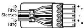
Balanced Stereo Input
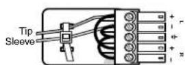
Unbalanced Mono Input
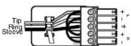
Balanced Mono Input (high impedance)
Figure 2. Wiring for Analog Input (Input 5)
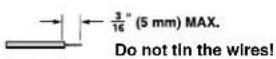
NOTES: • The length of the exposed wires in the stripping process is critical. The ideal length is 3/16 inches (5 mm). Any longer and the exposed wires may touch, causing a short circuit between them. Any shorter and the wires can be easily pulled out even if tightly fastened by the captive screws.
- Do not tin the wires. Tinned wire does not hold its shape and can become loose over time.
For more information about input formats, see "Front Panel Features and Operations" on page 6 and the "Source Formats" section on page 61.
③ Audio outputs — Outputs are balanced or unbalanced line level analog signals that feed into multichannel amplifiers for configurations up to 7.1 surround sound. For more information about Speaker Setup, see page 13.
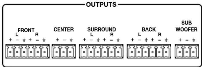
Figure 3. Audio Outputs
Individual output settings are configured through the SSP 7.1 Setup and Control Software (see page 30) or SIS commands (see page 86):
Mono — Output is through the center channel only but can be reconfigured to be output through the left and right front channels. In the absence of a center channel, mono is also output through the left and right front channels.
2-channel (stereo) — Only the front left and front right channels are used.
2.0 to 2.1 surround configurations — Audio is output through front left and front right channels with (2.1) or without (2.0) a subwoofer.
3.0 to 3.1 surround configurations — Audio is output through front left, front right, and center channels with (3.1) or without (3.0) a subwoofer.
4.0 to 5.1 surround configurations — Audio is output through a combination of front left and right, left and right surround, center and subwoofer channels.
6.0 to 6.1 surround configurations — Adds a back channel to 5.0 or 5.1 configurations. The back left channel receives the sixth channel information and serves as the center back speaker in this configuration.
7.0 to 7.1 surround configurations — Both the back left and right channels are active. Listening modes designed for 6.1 channel outputs pass the same signal to both the back left and right channels. Listening modes designed for 7.1 channel outputs pass separate signals to each channel to produce a stereo back sound effect.
For more information about speaker configuration and output formats, see the "Listening Mode Options and Usage" section on page 66.
④ RS-232 port — The SSP 7.1 can be configured using the SSP 7.1 Setup and Control Software or SIS commands, using this 3-pole captive screw connector (or the 2.5 mm Tip Ring Sleeve (TRS) mini jack plug on the front panel).
For more information about the SSP 7.1 Setup and Control Software, see page 22. For more information about SIS commands, see page 78.
RS-232
TxRx ±

Front Panel Features and Operation
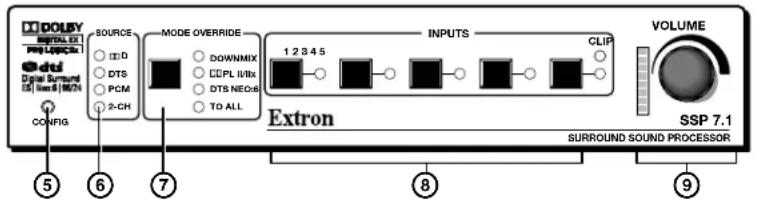
Figure 4. SSP 7.1 Front Panel Features
⑤ Configuration port — The SSP 7.1 can be configured using Extron Simple Instruction Set™ (SIS™) commands through this 2.5 mm Tip Ring Sleeve (TRS) mini jack plug (or through the 3-pole captive screw connector on the rear panel). For more information about SIS commands, see page 78.
NOTE: Both the rear panel RS-232 port and the front panel configuration port can be used at the same time. Neither has precedence. The SSP 7.1 responds to commands in the order received.
Source Format
⑥ Input source format indicator — The bank of four LEDs identify the format of the audio input.
- Dolby Digital (D): Dolby Digital 2/0, Dolby Digital 2/0 Surround, Dolby Digital 5.1, or Dolby Digital Surround EX.
- DTS: DTS 2-Channel, DTS Digital Surround, DTS 96/24, DTS-ES Matrix 6.1, DTS 96/24 ES Matrix 6.1, or DTS-ES Discrete 6.1.
• PCM: 2-channel uncompressed digital source format.
NOTES: • A digital signal that does not have a supported sampling rate or is compressed PCM is considered an unrecognized signal and is muted.
- When a DVD player is paused during playback, the SSP 7.1 may or may not continue to receive source format information from the DVD player. Some players continue to send the same source format information in a loop, allowing the SSP 7.1 to retain the previous settings. Other DVD players completely disconnect the signal from the SSP 7.1 (unlocked state), so that the active input blinks as if there is no connection present. The remainder of DVD players change the source output to PCM without an actual signal being sent (digital silence). During digital silence, the PCM LED lights but the 2-CH source LED does not.
2-Channel (2-CH):
• Any source coming through analog input 5.
- If a PCM digital signal is present on any of the digital inputs, both the PCM and the 2-CH LEDs light.
- If a Dolby Digital 2/0 or Dolby Digital 2/0 Surround source is present, both the D and the 2-CH LEDs light.
- If a DTS 2-Channel source format is present, both the DTS and 2-CH LEDs light.
To understand more about source formats, see page 61.
Mode Override Selection
⑦ Mode Override selector — The SSP 7.1 has a wide range of listening modes, although not all listening modes are compatible with every source format. The speaker configuration of the system may further limit which listening mode is available for a source format. Other factors, such as the room layout and listener preferences, may also influence the listening mode selection.
The SSP 7.1 has default listening modes associated with each source format. The front panel provides the user with a limited set of Mode Override settings. These can change the listening mode that is associated with a specific combination of source format and input. The override selections can be further defined using the SSP 7.1 Setup and Control Software, or SIS commands.
The new, user-defined listening mode continues to be associated with that source format until Mode Override is used, again, to associate a new listening mode with the source format. To select a listening mode:
- Use the push button to toggle through the available listening modes. When no mode override is chosen, none of the LEDs light, indicating that a user-defined listening mode is in use. Otherwise, one of the four LEDs shows the current selection.
- Release the button when the desired LED is lit to select that listening mode. If a listening mode is not an available option for the current input source, toggling the button skips that mode and goes to the next available mode.
- If required, further define the selection using the SSP 7.1 Setup and Control Software Listening Mode Setup Tab (page 45).
The mode override selections that are available through the front panel are:
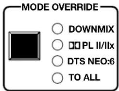
- Downmix (DOWNMIX) — Downmixes any multichannel source format (digital inputs only). It also downmixes a 2-channel source format, if the listening mode is set to mono.
It is further defined from the Setup and Control Software (see page 48). Options include:
- Stereo, output on left front and right front channels.
- Mono, output to center channel only or to left and right front channels equally.
- Dolby Pro Logic II/IIx (PL II/IIx) — uses Dolby Pro Logic II or Dolby Pro Logic IIx surround processing technology.
- Dolby Pro Logic II extends 2-channel sources to output 5.1 channels. It can be further defined by control software as either Dolby Pro Logic II Movie (default) or Dolby Pro Logic II Music.
- Dolby Pro Logic IIx extends 2-channel sources to output 6.0 to 7.1 channels (depending on the speaker setup). It can be further defined by control software as either Dolby Pro Logic IIx Movie or Dolby Pro Logic IIx Music.
- Dolby Pro Logic IIx also provides an extended surround option for multichannel sources such as DTS Digital Surround or Dolby Digital 5.1.
- DTS Neo:6 (DTS NEO:6) — Uses DTS Neo:6 surround processing technology to extend analog or 2-channel digital source formats (PCM, Dolby Digital 2/0, Dolby Digital 2/0 Surround, DTS 2-Channel) to output up to 7.1 channels. It is further defined by control software as either DTS Neo:6 Cinema (default) or DTS Neo:6 Music.
- To All (TO ALL) — Distributes a mono or 2-channel source to all applicable channels.
• Mono sources are sent to all available output channels, including center.
- 2-channel sources are sent to all stereo pairs only.
- Multichannel sources are downmixed and output to Mono to All or Stereo to All, as defined by the user.
- Digital or analog stereo sources may be output to Mono to All or Stereo to All, as defined by the user. If Mono to All is selected, the signal is downmixed to mono before being output to all channels.
NOTE: If an analog mono source is on the left channel, Stereo to All listening mode outputs only to the left channels of available stereo pairs. A right channel analog mono source is output only to the right channels of available stereo pairs.
When used in conjunction with the Input buttons, the Mode Override button is used to mute all outputs (see page 10).
The Mode Override button is used to perform a complete system reset (see "Complete System Reset" on page 10).
To learn more about listening modes, see "Listening Mode Options" on page 66. To learn how listening modes depend on both source format and speaker configuration, see "Source Formats and Listening Modes with Different Speaker Setups" on page 75.
Input Selection
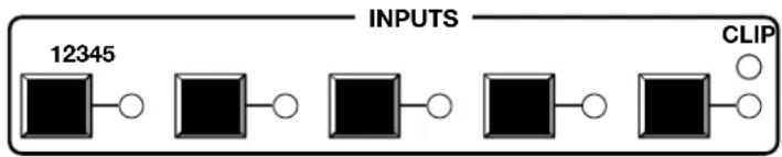
Figure 5. SSP 7.1 Input Selection Switches
⑧ Input selections — Push one of the buttons to select between five possible audio inputs. The LED next to the currently active input lights.
In conjunction with the Mode Override button, the input buttons are used to mute all outputs (see page 10).
The input buttons are also used to enable or disable front panel security lockout (executive mode). For more information, see page 12.
In conjunction with the volume adjust knob, the analog input (Input 5) is used to set analog input gain level for the analog source (see page 11).
The SSP 7.1 accepts four digital inputs and one analog input (see Rear Panel Features on page 4):
- Inputs 1 and 2 accept digital signals through S/PDIF optical cables. The optical cable supports TOSLINK or TOSLINK-compatible optical connectors that conform to IEC-958, S/PDIF standards.
- Inputs 3 and 4 accept digital signals through S/PDIF coaxial cables.
All four digital inputs accept 16-24 bits PCM audio at 32, 44.1, 48, 88.2, and 96 kHz sample rates. They support Dolby Digital and DTS source formats.
NOTE: For digital inputs, if there is no valid clock signal at the input and no lock is achieved, the LED associated with the source blinks twice per second.
- Input 5 accepts a balanced or unbalanced analog input through a 5-pin captive screw connector. The unit can be configured to accept:
- A stereo signal
• A mono signal from the right channel
• A mono signal from the left channel
• A mixed sum of right and left channels
The input can also be selected using the SSP 7.1 Setup and Control Software (see Input Source on page 26).
Mute Output
When the mute state is enabled, all channels are muted simultaneously. To toggle between mute and unmute:
- Press and hold the active input button (the button next to the LED that is lit).
- While still holding the active input button, press the Mode Override button.
When the mute state is enabled, the individual LEDs of the Volume Adjustment LED bar light in sequence from the top down. This scrolling down pattern repeats while the mute state persists.
NOTES: • Selecting another input button while the mute function is enabled, disables the mute function.
- Adjusting the volume control encoder to change the volume (or the analog input gain) settings while the mute function is enabled, disables the mute function and increases (or decreases) the volume (or gain) from its previous setting.
- If SIS commands have been used to mute a specific channel, muting and unmuting all channels also unmutes the channel that was specifically muted. It does not remain in its previously muted state.
All channels can also be muted using the SSP 7.1 Setup and Control Software (see Master Volume and Mute on page 29).
Complete System Reset
The SSP 7.1 has three levels of System Reset.
Standard system reset — All parameters that can be adjusted by the control program are reset to default.
Factory reset — In addition to resetting all the parameters of the standard system reset, the baud rate for communicating with the computer is also reset.
Complete system reset — In addition to resetting all the parameters of the factory reset, the firmware is reset to the factory-installed version.
The standard and factory resets are performed using SIS commands (see the System Reset SIS commands on page 94).
To perform a complete system reset, hold the Mode Override button while shutting off and restoring power.
Volume Adjustment
⑨ Volume adjust knob and LED bar or Analog input gain level control and LED bar — Use the rotary encoder to adjust the output volume from 0 (-100 dB) to 100 (0 dB). The default setting is 50 (-50 dB).
The degree to which the volume is incremented or decremented for each step the encoder is turned, depends on the current volume setting (see the last column in the table below).
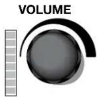
As the volume increases or decreases, the LED bar lights to indicate the current volume range, as shown in the table below. As the volume is increased or decreased within a volume range, the top LED to be lit flashes once. If the knob is turned past maximum volume, all 8 LEDs flash, for as long as the knob continues to be turned.
| Volume steps for each LED (dB) | LEDs lit Increment | (dB/knob step) |
| >0 All LEDs blink if user tries to turn knob further | ||
| 0 All 8 LEDs on | 1 | |
| -4 to -1 All 8 LEDs on | ||
| -9 to -5 Bottom 7 LEDs on | ||
| -14 to -10 Bottom 6 LEDs on | ||
| -19 to -15 Bottom 5 LEDs on | ||
| -29 to -20 Bottom 4 LEDs on 2 | ||
| -49 to -30 Bottom 3 LEDs on | 4 | |
| -69 to -50 Bottom 2 LEDs on | ||
| -99 to -70 Bottom LED on | 5 | |
| -100 All LEDs off | ||
Table 1. Volume Level and Lighting of LED Bar
The volume can also be controlled using the SSP 7.1 Setup and Control Software (see Master Volume and Mute on page 29).
Analog Input Gain Adjustment
Alternatively, the rotary encoder controls the gain level of the analog signal on input 5. Analog input gain is adjustable from 0 dB (fully counterclockwise) to +24 dB (fully clockwise).
To adjust input gain, press and hold the Input 5 button, while turning the rotary encoder.
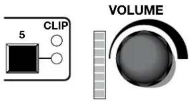
NOTES: • If the gain level is too high, clipping may occur. When clipping occurs, the red LED above the Input 5 button lights.
- When using Mono or Mono to All listening mode, the left and right signals are summed (in the digital domain), which can cause a boost in level up to 6 dB. This type of clipping does not cause the clip indicator LED to light but is audible. If using a mono mode, it is recommended that the input gain be reduced by 9 dB below clipping to prevent clipping from occurring.
The LED bar lights from the bottom up to indicate the current gain level. No LEDs lit indicates no gain (0 dB, or unity gain); all the LEDs lit indicates maximum gain (24 dB). Each solidly lit LED represents 3 dB. A slowly blinking LED indicates an additional 1 dB or a quickly blinking LED indicates an additional 2 dB:
| Number of LEDs lit solidly | Gain (dB) | ||
| No Blinking Slow | Blinking Fast Blinking | ||
| 8 24 - - | |||
| 7 21 22 23 | |||
| 6 18 19 20 | |||
| 5 15 16 17 | |||
| 4 12 13 14 | |||
| 3 9 10 11 | |||
| 2 6 7 8 | |||
| 1 3 4 5 | |||
| None No LEDs | lit; 0 dB 1 2 | ||
Table 2. Gain level and lighting of LED bar
The analog input gain can also be controlled using the SSP 7.1 Setup and Control Software (see Master Volume and Mute on page 29).
Front Panel Security Lockout (Executive Mode)
When the front panel is locked, the user cannot make any changes from the front panel (except disabling the security lockout). If the user attempts to make changes with the front panel locked out, all the input LEDs flash simultaneously. The lockout does not block changes made using SIS commands or the SSP 7.1 Setup and Control Software. To lock out the front panel:
- Press and hold the active input button (the button next to the LED that is lit).
- While holding the active input button, press and hold any other input button. All the LEDs blink in ascending order (from 1 to 5) and then the active input button lights.
- The front panel is unlocked in exactly the same way. All the LEDs blink in descending order (5 first and 1 last) and then the active input button lights.
This feature can also be set, using the SSP 7.1 Setup and Control Software (see Front Panel on page 52).
Setup
This section provides background information about arranging speakers in a room and about some of the settings that can be adjusted by the SSP 7.1 Setup and Control Software. Extron strongly recommends that the control software is used to make any configuration changes to the SSP 7.1. (See "Setup and Control Software" on page 22).
- Speaker Setup
- Bass Management
- Speaker Delay Settings
- Test Signals
• Output Channel Trim Settings
• Listening Mode Settings
• Dynamic Range Compression Control - Tone Controls
• Volume Output - Equalization
Speaker Setup
The following figures show the recommended speaker placement, relative to the listener, for a five, six, or seven speaker system and for subwoofer placement.
NOTE: All speakers should be angled inwards so that they face towards the listener.
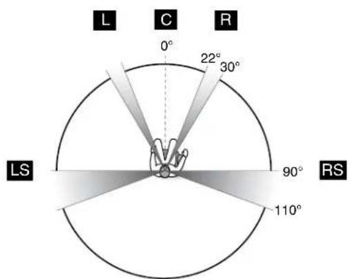
Figure 6. Five Speaker Setup
For an explanation of speaker abbreviations, see page 14.
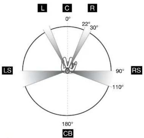
Figure 7. Six Speaker Setup
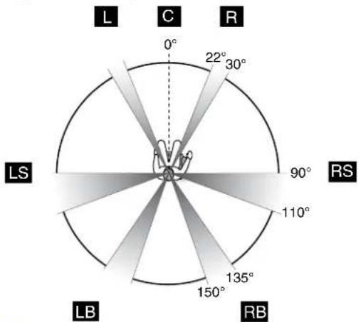
Figure 8. Seven Speaker Setup
Abbreviations
C = Center CB = Center Back (Six Speaker Setup only) L = Left LB = Left Back (Seven Speaker Setup only) LS = Left Surround R = Right RB = Right Back (Seven Speaker Setup only) RS = Right Surround SW = Subwoofer
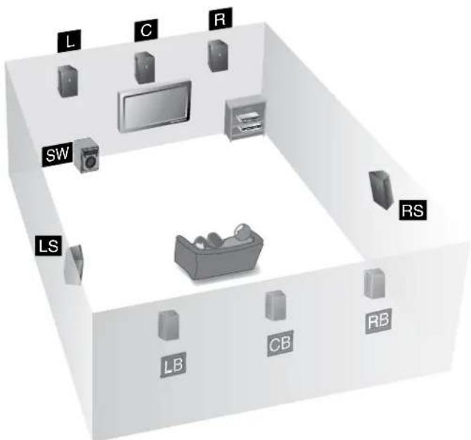
Figure 9. Subwoofer Placement
NOTES: • To produce a good bass response from the subwoofer, it should be located at the front of the room, somewhere between either corner and a point about one third of the way along the front wall.
- The output channel used for the Left Back speaker (in 7.1 configurations) is also used for the Center Back speaker (in 6.1 configurations).
Bass Management
Low frequency sound is usually better handled by the subwoofer. Bass management creates the subwoofer channel by separating the low frequency information from the satellite speakers at a user-defined crossover point. This is summed with the Low Frequency Effects (LFE) information encoded in the source format. When no subwoofer is present, subwoofer content is sent to speakers set to Large (excluding the center speaker).
Speaker Size Settings
This feature sets bass management on or off for a particular speaker, defining the frequency range output by that speaker. These settings also enable or disable the subwoofer and set the crossover frequency.
- Left and right front speakers and left and right surround speakers are set in pairs.
• The center speaker is set as an individual speaker. - Back speaker(s) can be set as a single speaker or as a pair of speakers, depending on the system configuration.
Small — Bass management is on for that speaker. The output to each speaker (other than the subwoofer) is limited to frequencies above the crossover frequency. By default, center and surround speakers are set to Small.
Large — Bass management is off for that speaker. The full range of audio frequencies from the audio source is fed through the output of each individual channel. This may be set in the absence of a subwoofer. By default, front speakers are set to large.
When there is no subwoofer, all speakers set to Large (except the center channel) receive the summed audio from the filtered low frequency signals of speakers set to Small.
None — This mode prevents any signal from being sent to that output channel. It is not an option for front speakers.
One Small Speaker, Two Small Speakers, One Large Speaker, Two Large Speakers, or None (Surround back speakers only) — This mode determines whether the audio output channels for the back speaker(s) are passed to the left back and right back (in 7.1 setups) or to the center back (in 6.1 setups).
If either of the one speaker options are chosen, the highest possible number of outputs is 6.1 speakers. In this case, the output is directed to the left back channel output.
If either of the two speaker options are chosen, the SSP 7.1 is able to output up to 7.1 channels. Source formats with discrete or matrix mixed 6.1 encoded channels output the surround back channel signal equally to the left and right back channels. Dolby Pro Logic IIx and DTS Neo:6 listening mode options output a stereo signal to the left and right back channels.
NOTE: If the surround speakers have been disabled, the back speaker options are also disabled.
By default, the back speaker is set to None, which prevents a signal from being output on the back channel(s).
Subwoofer — This option allows the subwoofer to be enabled or disabled. When the subwoofer is enabled, the signal contains filtered low frequency signals from speakers set to Small in addition to the LFE signal from the source format. If the subwoofer is absent or disabled, the LFE signal is mixed with the bass information of all speakers in the system that are set to Large, except the center speaker.
NOTES: • When the surround and back speakers are set to None, all multichannel input signal formats are downmixed and output on all remaining channels.
- In addition, in the absence of a center channel, mono signals are output equally between the front left and front right channels. Multichannel sources are downmixed to all remaining channels, but Mono to All and Stereo to All options are disabled. Choosing Mono listening mode first downmixes the multichannel source and outputs it to the front left and right channels equally as a dual mono signal.
Crossover Frequency — The crossover frequency sets the boundary below which the low frequency signals from designated output channels are incorporated into bass management. Low frequency signals are only taken from speakers that have been set to Small (see "Speaker Size Settings" on page 15). The bass management signal is passed to the subwoofer (if present) or speakers that have been set to Large (except for the center speakers) if a subwoofer is not present.
The crossover frequency can be adjusted within the range of 40 Hz to 250 Hz, with a default setting of 100 Hz. Speakers set to Small (see "Speaker Size Settings" on page 15) play only signals above the set frequency.
Speaker Delay Settings
There are two different signal delays that compensate for different needs.
Compensation delay — In a room where speakers are not equidistant from the listener, sound from the closest speaker reaches the listener before sound from the farthest speaker. This feature allows the user to enter the speaker distance value for each speaker output channel. The application calculates the delay values for the closest speakers, up to 100.0 ms, so that all audio arrives at a central location (the "sweet spot") at the same time.
Lip sync offset — Video delays occur due to changes in programming from a source (TV, Cable, Satellite, or DVD player) and also if the video signal has to be processed through another device between the source and the display. The lip sync offset feature allows the user to delay the audio sent to all output channels so that video and audio output are synchronized.
Since each source may need a different level of compensation, the lip sync offset for each input is independently adjustable from 0.0 to 100.0 ms. Apply lip sync offset to the audio until what is heard matches up with what is seen on the display.
To configure these settings using the SSP 7.1 Setup and Control Software, see "Speaker Delay Tab" on page 32.
Test Signals
Test signals are used during setup to calibrate the level for each channel and to ensure proper connection between the individual output channels of the SSP 7.1 and the line level input channels of an audio signal processor, a receiver with built in amplifier, or a stand alone amplifier that powers the loudspeakers.
The three options for test signal source are pink noise, Dolby noise, and an external source. By default, the test signal is switched off.
Pink Noise — Pink noise is a random signal, generated by the SSP 7.1, with all audio frequencies present. It provides equal energy per octave to provide a flat response over all frequencies. The main purpose of pink noise is to calibrate the interaction of a speaker with its environment.
Dolby Noise — Dolby noise provides a bandpass-filtered noise, centered at 750 Hz with a 12 dB/octave roll off. This signal is also generated by the SSP 7.1 and is used to set speakers to the same level when calibrating the room.
Active Input — This option requires an external test signal source, such as a signal generator, played through the selected input source. Generally, this is a device with an analog signal output, with the SSP 7.1 analog input used as the active input.
Signal generators are usually used to test specific decoding mode outputs. When the External Source option is chosen, the speakers that receive the test signal can be specified.
To calibrate speaker output, use any of these test signals with the SSP 7.1 Setup and Control Software, see Test Signals on page 36.
Output Channel Trim Settings
This control adjusts the output channel trim level for each output channel to match the levels to the unique needs of any listening environment. The level can be adjusted within the range from -24 dB to +12 dB. The default setting for each speaker is 0 dB. See Output Trim on page 39 for more information.
Listening Mode Settings
The SSP 7.1 provides a range of settings that refine the sound distribution for each listening mode, depending on the decoding mode that has been selected.
Dolby Pro Logic II or IIx Music
Dimension control — This feature alters the ratio of L+R to L-R for two-channel input signals, which adjusts the sound field towards the front or towards the back. The available settings are Front, Neutral, or Back. The default setting is Neutral.
Center width control — Pro Logic decoding produces a single center signal that comes from the center speaker. If there is no center speaker, a “phantom” center image is produced that is split between the right and left speakers.
If right, left, and center speakers are present, center width control allows variable adjustment of the center image so that is heard only from the center speaker, only from the right and left speakers, or from all three speakers in varying degrees.
There are up to eight different settings, with each corresponding to a specific calculation angle ( ). When the setting is 0, the sound comes from the center speaker, when the setting is 7, the sound is from the L/R speakers. The default setting is 3.
| Control Position Calculation Angle (Φ) | C Level (dB) L/R | Level (dB) |
| 0 0.0 0.0 Off | ||
| 1 20.8 -0.6 -12.0 | ||
| 2 28.0 -1.1 -9.6 | ||
| 3 36.0 -1.8 -7.6 | ||
| 4 54.0 -4.6 -4.8 | ||
| 5 62.0 -6.6 -4.1 | ||
| 6 69.2 -9.0 -3.6 | ||
| 7 90.0 Off -3.0 |
NOTE: The level of the center speaker (C Level) is related to cosine . The level of the left and right speakers (L/R Level) is related to sine .
Panorama control — This feature extends the center width control, so that all or part of the center image can be heard from the surround speakers for a “wraparound” effect. The feature may be On or Off. The default setting is Off.
DTS Neo:6 Music or Cinema
Center image control — The center image control varies the amount of attenuation applied to the left and right channel information of the input source that is used for creating the output center channel effects. When it is set to 0, the mixed input signal information, intended for use in creating the center output channel of the DTS Neo:6 listening modes, is filtered back to the front left and right output channels. This creates the effect of spreading the centralized audio signal across all three front output channels. When this control is set to 10, the matrixed information intended for the center output channel effects is fully attenuated, allowing the center channel to create a more centralized effect from the front channels.
The default setting for DTS Neo6: Music is 3. The default for DTS Neo6: Cinema is 10.
Dynamic Range Compression Control
This control is available only with Dolby Digital and DTS source formats that have a Dynamic Range Compression flag.
This control adjusts the gain applied to Dolby Digital or DTS listening modes to compress the signal outputs during the decoding process. The three possible settings are None, Minimum, and Maximum. The default setting is None.
Off — The signal is uncompressed and is played with the full original dynamic range.
Minimum — The audio is partially compressed. In this mode, the volume of the loudest passages is reduced but quieter passages are kept at their original level. This level is recommended for normal listening.
Maximum — The audio is fully compressed. This level is recommended for environments where loud audio is not permitted.
NOTE: DTS source formats have only two states (On and Off) for dynamic range compression. Therefore, Minimum and Maximum both apply the same dynamic range compression.
Tone Controls
These controls regulate the bass and treble settings for the system. To adjust the bass or treble tone controls, see Tone Controls on page 27.
Bass — The bass control regulates the amount by which low frequency signals are boosted or cut (see figure below). It is applied to outputs for all speakers, including the subwoofer.
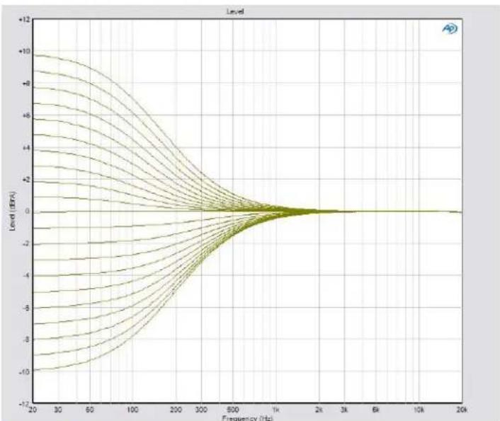
line
| Frequency (Hz) | Level (dB) | | -------------- | ---------- | | 20 | -10 | | 30 | -8 | | 60 | -6 | | 100 | -4 | | 200 | -2 | | 300 | 0 | | 600 | 0 | | 1k | 0 | | 2k | 0 | | 3k | 0 | | 6k | 0 | | 10k | 0 | | 20k | 0 |Figure 10. Bass Range
Treble — The treble control regulates the amount by which high frequency signals for all speakers, except the subwoofer, are boosted or cut (see figure below).
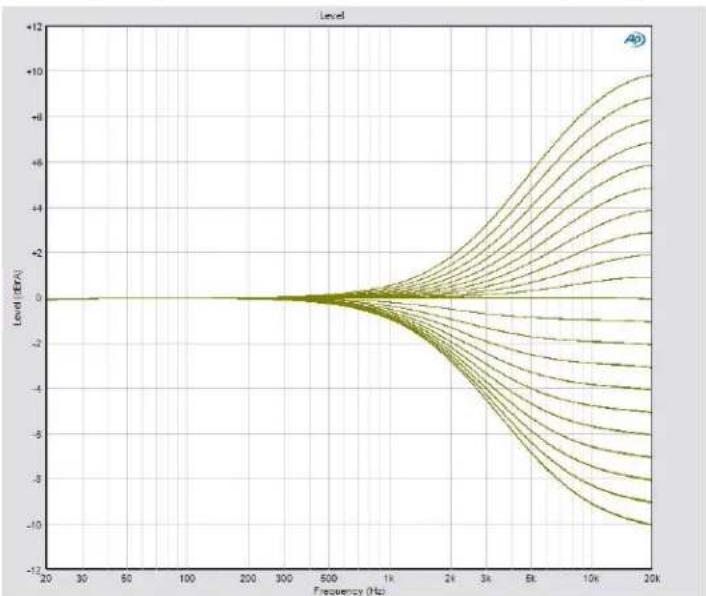
line
| Frequency (Hz) | Level (EPA) | | -------------- | ----------- | | 20 | 0 | | 30 | 0 | | 50 | 0 | | 100 | 0 | | 200 | 0 | | 300 | 0 | | 500 | 0 | | 1K | -2 | | 2K | -4 | | 3K | -6 | | 5K | -8 | | 10K | -10 | | 20K | -12 |Figure 11. Treble Range
Volume Output
This control sets the volume of the audio output through all channels, globally, to either Variable (the default value) or Fixed.
Variable — When the Volume output is set to Variable, the volume can be attenuated using the front panel knob, the SSP 7.1 Setup and Control Software, or SIS commands.
Fixed — The Fixed option sets the volume to the current attenuation level. Likewise, all the Output Channel Trim levels (see Output Trim on page 39) are fixed at the values they had immediately before the Volume Output was set to Fixed.
When Fixed is selected, the volume cannot be adjusted through the front panel knob, by the SSP 7.1 Setup and Control Software, or by SIS commands.
Equalization
Parametric equalization (or parametric "EQ") allows the control of amplitude of each band, center frequency (which can be shifted, widened, or narrowed) and bandwidth (which may be labeled "Q" for Quality). Parametric equalization is used to improve the audio output in a specific acoustic environment.
Resonance reduction — Reduces the level at specific frequencies that are too loud.
Speaker compensation — Compensates for peaks and dips in individual speaker output response.
Tonal enhancement — Increases the level of frequencies within a broad or narrow range that sound too quiet.
Setup and Control Software
The SSP 7.1 Setup and Control Software provides an intuitive, easy to operate, graphical user interface that allows the user to configure the audio system quickly and efficiently. It provides more options than the front panel. As selections are made, only the options that are available for the current configuration are displayed by the software. Extron strongly recommends using the SSP 7.1 Setup and Control Software for all configuration.
The program comes on a disk, supplied with the unit. It can also be downloaded, free of charge, from the Extron Web site (www.extron.com).
The following sections describe:
• Installing the SSP 7.1 Setup and Control Software
• Live and Emulate Modes
- Running the SSP 7.1 Setup and Control Software
- SSP 7.1 Setup and Control Software Help File
- Firmware Updates
Installing the SSP 7.1 Setup and Control Software
The minimum system requirements for installing the program on the computer are:
- Operating system — Microsoft Windows® 2000 or higher
- CPU — Intel® Pentium® II processor with a 400 MHz clock speed or faster
• Hard disk space — At least 10 MB
• Memory — At least 64 MB of RAM
• Device connection — Serial COMM Port
Insert the disk provided into the CD or DVD ROM drive of the computer. If the setup program does not start automatically, run Launch.exe from the CD or DVD ROM directory in Windows My Computer. Select the Software tab, locate the SSP 7.1 Setup and Control Software, and click Install. Follow the on-screen instructions to install the program.
Alternatively, go to the Extron Web site, click on the Download tab, and click on the Software option in the left sidebar. Navigate to the SSP 7.1 Setup and Control Software and click Download. Follow the on-screen instructions to install the program.
By default, the Installer program creates a C:\Program Files\Extron\SSP7.1 folder to contain the SSP 7.1 Setup and Control Software. An icon may also be placed on the Windows desktop.
NOTE: Updating the SSP 7.1 Setup and Control software may also require a more recent version of the firmware to be installed (see Firmware Updates on page 56).
If the new software detects an old version of the Firmware, a pop-up window informs the user that the firmware should be updated and also prompts the user to save the existing configuration for reloading onto the SSP 7.1 when the new firmware has been installed.
When the firmware has been updated, open the SSP 7.1 software in Emulate mode (see below) and open the saved configuration. Click on the Live button and, when the Synchronize with Device pop-up appears, select Push the data from this configuration to device, overwriting any data currently in it. option.
Live and Emulate Modes
The SSP 7.1 Setup and Control Software offers a choice of Live or Emulate mode. In Live mode, any changes made using the software directly affect the configuration of the sound processor.
In Emulate mode, the computer is not connected to the sound processor and any changes you make must be saved as an *.esp file. The file can be used later to update the configuration of the sound processor when the computer is directly connected to the SSP 7.1 in Live mode.
You may choose between Live and Emulate modes either when the program first starts up in the Connect to Device? dialog box (see page 24) or, when the main program window is running, using the Live and Emulate buttons in the top right corner (see the figure at right). You can also toggle between the two modes, by using the F5 and F6 keys or clicking on Connect... (F5) or Disconnect (F6) under the Device menu (see page 52).
When you switch from Emulate to Live mode, you are prompted to synchronize the settings in the SSP 7.1 Control and Setup Software with the current
configuration in the SSP 7.1 device. Select Push to overwrite the configuration in the device with the software settings made in Emulate mode, or select Pull to overwrite the software settings with the configuration in the device.
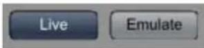
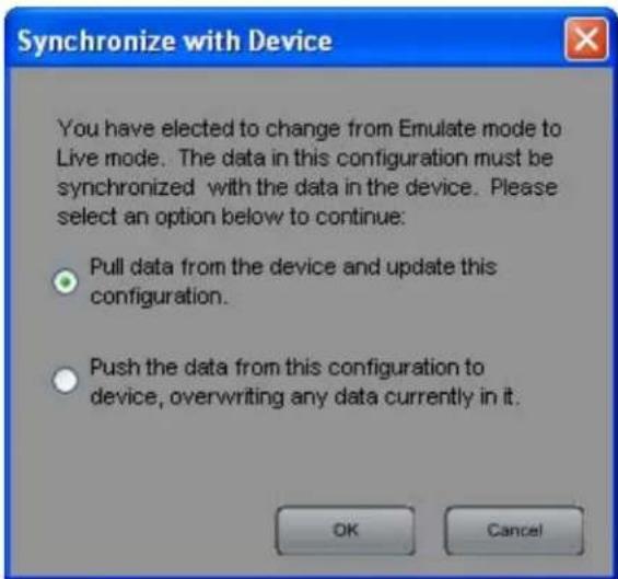
Figure 12. Synchronize with Device Dialog Box
When the SSP 7.1 Control and Setup software is opened directly to Live mode, the current configuration in the device is read from the SSP 7.1 unit, automatically overwriting the settings in the software. When the program is closed, you are prompted to save any changes that have been made during that session.
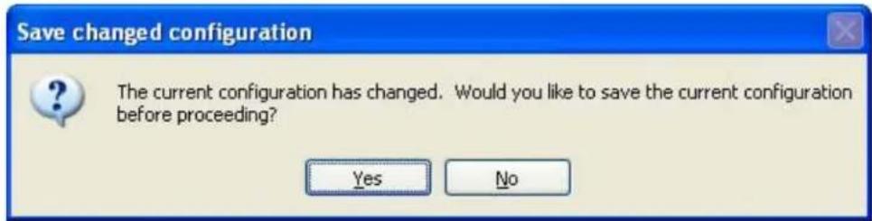
Figure 13. Save changed configuration Box
Running the SSP 7.1 Setup and Control Software
Connect to device? Dialog Box
The computer must be connected to the SSP 7.1 using either the RS-232 captive screw connector on the rear panel or the Config port on the front panel.
To start the program, click on the desk-top icon or click on the Windows Start button and select All Programs > Extron Electronics > SSP7.1 > SSP7.1. When the program launches, the "Connect to device?" dialog box (shown below) opens.
To work offline in Emulate mode, check the Emulate/Work offline box. To connect directly to the SSP 7.1, leave the box unchecked. See the previous section, "Live and Emulate Modes," for a description of each mode.
If you choose to work directly with the SSP 7.1:
- The Device name (SSP 7.1) and Connection Method (RS-232) are already entered and no other selections are available for these fields.
- Select the correct Com Port and Baud Rate (default 38400).
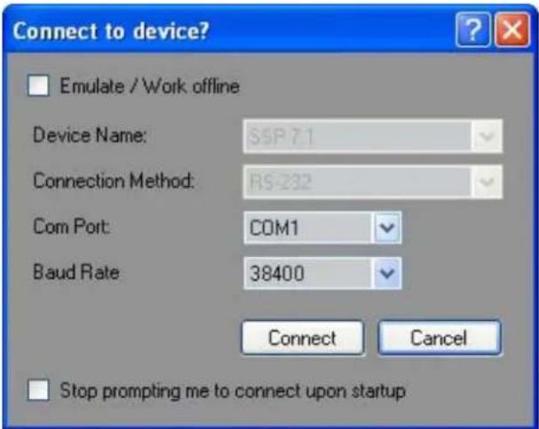
Figure 14. Connect to device? Dialog Box — Live Mode
- Click the Connect button (or Cancel to exit the program).
If you select Emulate, click on the Work Offline button (or Cancel to exit the program).
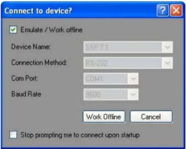
Figure 15. Connect to device? Dialog Box — Emulate Mode
NOTE: When Emulate/Work Offline is selected, the Connect button is replaced by a Work Offline button. Instead of establishing a connection with the sound processor, the program allows you to create a configuration that can be saved as a file and used to update the configuration of the sound processor when the program is in Live mode.
When the program opens, you may still toggle between Live or Emulate modes by using the buttons in the top right corner of the program window, as described in "Live and Emulate Modes" on page 23.
If you check the "Stop prompting me to connect upon startup" box, the next time the program opens, this dialog box is not shown and the program automatically opens in Emulate mode. Click the Live button in the program window to switch to Live mode.
To re-enable this box, use the menu system to navigate to Options>Re-enable Dialogs (see Re-enable Dialogs on page 53). This clears the check box in all dialog boxes and all previously disabled pop-up messages occur regularly again.
Main Tab
The program opens with the Main tab selected. Two other tabs are available: Speaker Setup (page 30) and Listening Mode Setup (page 45). It is advisable to configure each tab in the sequence they appear at the top of the screen. Full instructions on how to configure each screen are available in the help file, which can be accessed under the Help menu option or by pressing F1 from within the program.
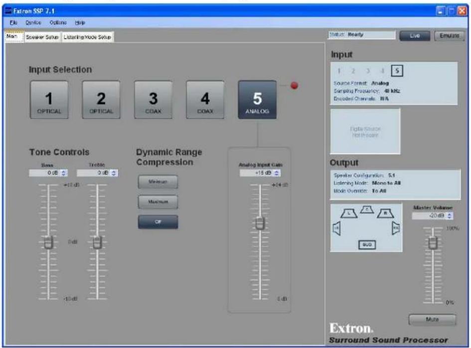
Figure 16. Main Tab
The Main tab offers the options that are available on the SSP 7.1 front panel:
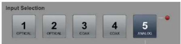
Input source — The five buttons allow the user to select between five possible audio inputs: four digital inputs and one analog input. The currently selected input is shown in blue; the other sources are shown in gray. Further information about the input sources is available in the Source Formats section on page 61.
flowchart
graph LR
    A["1 OPTICAL"] --> B["2 OPTICAL"]
    B --> C["3 COAX"]
    C --> D["4 COAX"]
    D --> E["5 ANALOG"]
Figure 17. Main Tab — Input Selection
Tone controls — Bass control adjusts the amount of low-frequency boost or cut applied to the audio outputs for all speakers, including the subwoofer. Treble control adjusts the amount of high-frequency boost or cut applied to the audio outputs for all speakers, except the subwoofer. Both controls are adjustable between -10 dB and +10 dB, and the current value is shown in the text box. Adjust the value in any of these ways.
- Grab and drag the slider bar to adjust tone in 1 dB increments.
- Click on one of the slider bars to make it active and use the up and down arrows beside the text box to adjust the tone in 1 dB increments.
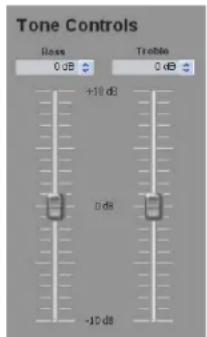
- Click on one of the slider bars to make it active and use the up and down keys on the keyboard to adjust the tone in 1 dB increments.
- Click in one of the text boxes and type a number between -10 and +10.
- Click on one of the slider bars to make it active and use the page up and page down keys on the keyboard to adjust the tone in 5 dB increments.
Analog input gain — This control is only available when input 5 (analog) is selected. It is locked and cannot be adjusted when inputs 1-4 are selected.
The Analog Input Gain control allows the gain to be adjusted between 0 dB and +24 dB. The current setting is displayed in the text box.
The gain can be changed in any of the following ways.
- Grab and drag the slider bar to adjust gain in 1 dB increments.
- Click on one of the slider bars to make it active and use the up and down arrows beside the text box to adjust the gain in 1 dB increments.
- Click on one of the slider bars to make it active and use the up and down keys on the keyboard to adjust the gain in 1 dB increments.
- Click in the text box and type a number between and +24 dB (do not type the "+" or "dB").
- Click on one of the slider bars to make it active and use the page up and page down keys on the keyboard to adjust the gain in 5 dB increments.
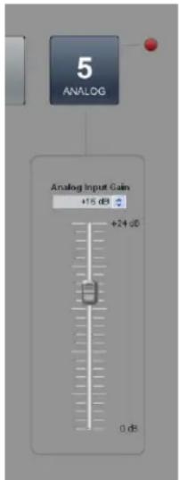
The red virtual LED lights when the input level is 0 dBFS or higher, indicating that the input level is too high.
NOTE: If the gain level is turned too high, clipping may occur (depending on the input volume). When clipping occurs, the red virtual LED next to the Input 5 button lights.
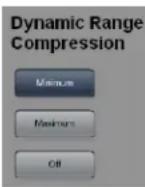
Dynamic Range Compression (only with Dolby Digital and DTS source formats that have a Dynamic Range Compression flag) — These buttons allow a choice of Off, Minimum, and Maximum. The default setting is Off. For more information about Dynamic Range Compression Control, see page 19.
Input and Output information bar — The Input and Output information bar, on the right side of the screen, is visible in all tabs and provides information about:
• The current input
- Selected input channel
- Source format
- Sampling frequency
- Encoded channels
• The current output
- Speaker configuration
- Listening mode
• Mode override selection
- Master volume
Mute
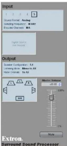
NOTE: While the Master Volume value and Mute status can be adjusted using the slider bar and button in this panel, the Input and Output status information in this information bar is read only.
Input status — The Input box indicates which input channel is being used. Underneath are three lines of information about the source format, the sampling frequency, and encoded channels.
The box underneath highlights the active channels for the audio source in blue.
L = Left front
C = Center
R = Right front
LS = Left surround
RS = Right surround
S = Surround (only available with 3/1 or 2/1 sources): LS and RS carry a mono surround signal.
SB = Surround back
LFE = Low Frequency Effect (primarily used for subwoofer channel output)
Further information about the source format configuration from the SSP 7.1 front panel can be found on page 6. To understand more about Source Formats, see page 61.
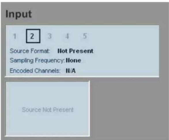
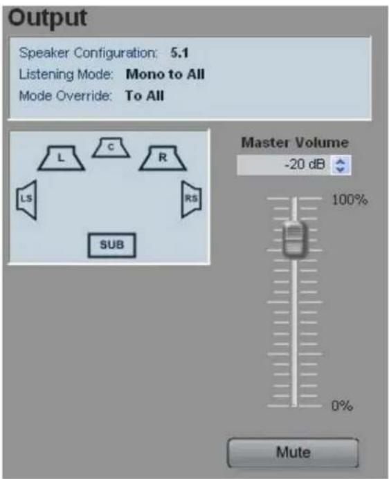
Output status — A text box indicates the speaker configuration, the current listening mode, and the mode override status.
Underneath, a box shows the current speaker configuration. Speakers that are available are highlighted in blue and speakers that are not available are not shown.
Speakers that are set to large (see Speaker Configuration on the next page) are represented by large icons and speakers that are set to small are represented by small icons.
Speakers that are present but have been muted are shown in red.
Master volume and mute — The output status section of the screen also contains the Master Volume adjustment and the Mute button.
The master volume can be adjusted between 0 (-100 dB) and 100 (0 dB). The current volume setting is displayed in the text box. The volume can be changed in any of the following ways:
• Grab and drag the slider bar to adjust volume in 1 dB steps.
- Click on the slider bar to make it active and use the up and down arrows beside the text box to adjust the volume in 1 dB steps.
- Click in the text box and type in a negative number in the box (corresponding to the attenuation, in dB, from the maximum volume). Typing a positive number resets to maximum volume (0 dB attenuation). Do not type the "dB."
- Click on the slider bar to make it active and use the up and down keys on the keyboard to adjust the volume in 1 dB steps.
- Click on the slider bar to make it active and use the page up and page down keys on the keyboard to adjust the volume in 5 dB steps.
The Mute button mutes or unmutes all channel outputs.
NOTE: Moving the volume or the analog gain sliders, or switching inputs disables the mute function and restores the volume settings.
Speaker Setup Tab
After completing the Main tab, the next tab is Speaker Setup, which is the first tab to allow system configuration that is not available from the front panel. The Speaker Setup tab provides access to four second-level tabs (Speaker Configuration, Speaker Delay, Testing & Output Trim, and Speaker Equalization).
Speaker Configuration Tab
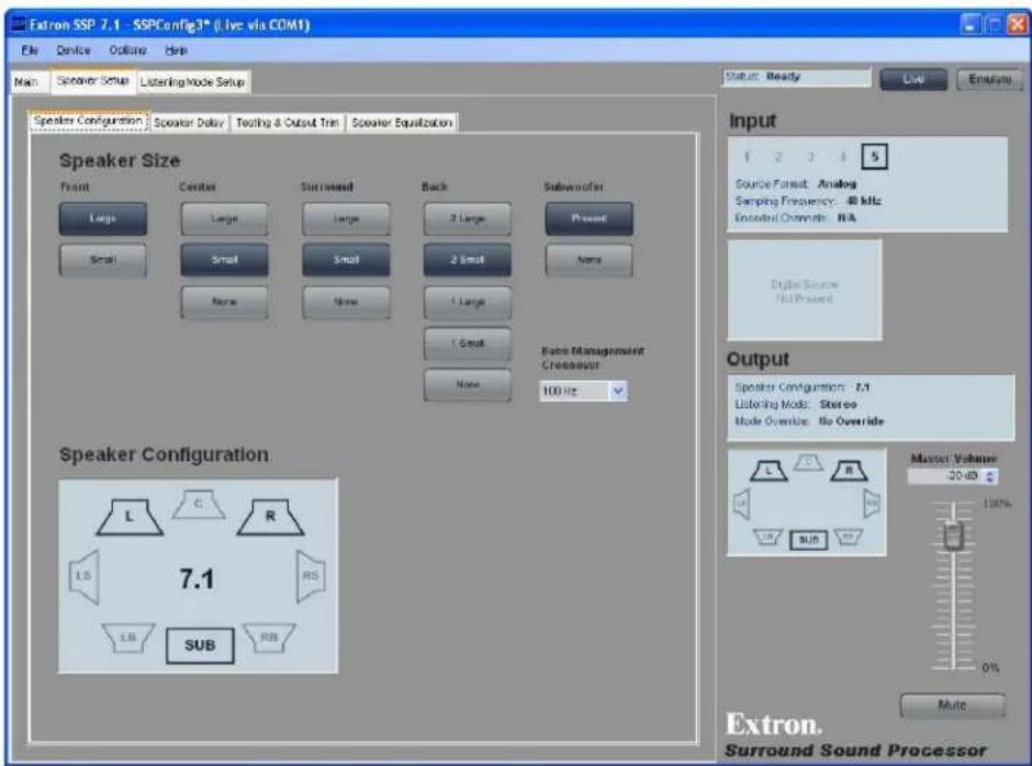
Figure 18. Speaker Configuration Tab
Speaker size
Speaker size determines whether or not bass management applies to that speaker. For more information about bass management and speaker size, see pages 15 and 16.
Speaker size settings — All the buttons in a single column offer mutually exclusive choices. Only one selection can be made from each column. For example, front speaker size must be set to either 2 Large or 2 Small. It cannot be set to both values or neither value.
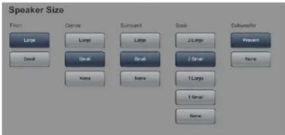
Figure 19. Speaker Size Settings
- Left and right front speakers and left and right surround speakers are set in pairs.
- The center speaker is set as an individual speaker.
- Back speaker(s) can be set as a single speaker or as a pair of speakers, depending on the system configuration.
- The subwoofer can be set to Present or None.
Small — Bass management is on (see page 15).
Large — Bass management is off (see page 16).
None — No signal is sent to the output for that channel, effectively removing the speaker from the current configuration. It is not an option for front speakers (see page 16).
One Small Speaker, Two Small Speakers, One Large Speaker, Two Large Speakers, or None (Back speakers only) — These options determine whether the audio output channels for the back speakers are output to the left back and right back (in 7.1 setups) or to the center back (in 6.1 setups). For more information, see page 16.
Subwoofer — This option allows the subwoofer to be enabled or disabled (see page 16).
Crossover — The crossover frequency sets the boundary below which the low frequency signals from designated output channels are incorporated into bass management (see
page 16). The crossover frequency is adjustable using the drop-down menu.
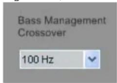
• From 40 - 80 Hz, increment and decrement in 5 Hz steps
• From 80 - 150 Hz, increment and decrement in 10 Hz steps
• From 150 - 250 Hz, increment and decrement in 25 Hz steps
Speaker configuration
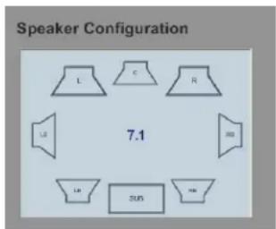
The speaker configuration is displayed in a graphics box that is very similar to the graphics box shown in the Input and Output information bar.
Only the speakers available in the current configuration are displayed.
If the speakers are set to Large, they are represented by large icons, as shown in the figure at right. If the speakers are set to Small, they are represented by small icons.
If the speakers are set to None, they are not available in the current configuration and are not displayed.
If the back speakers are set to 1 Large or 1 Small, the CB speaker, but not the LB and RB speakers, are shown (6.1
setups). If the back speakers are set to 2 Large or 2 Small, the LB and RB speakers, but not the CB speaker, are shown (7.1 setups).
Input and Output information bar
The Input and Output information bar is available from all GUI tabs and is described in detail on pages 28 and 29.
Speaker Delay Tab
After completing the Speaker Configuration tab, configure the Speaker Delay tab.
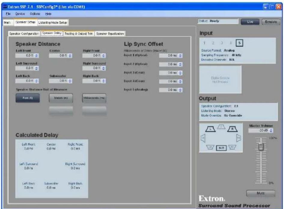
Figure 20. Speaker Delay Tab
These controls introduce a signal delay for each speaker that has not had its size value set to None. The two main reasons to adjust the signal delay are:
- To compensate for unequal distances between the speakers and the listener, which causes sound from different speakers to reach the listener at different times.
- To compensate for a lack of coordination between the audio and the accompanying video signal.
Speaker distance
When speakers are arranged in a room, there is a central location or "sweet spot" that offers the best listening point. However, even in that central location, the speakers are not necessarily all equidistant from the listener and the sound from the closest speaker reaches the listener before the sound from speakers that are further away.
Speaker distance settings delay the signals going to each individual speaker (from 0 to 100 ms) so that the signals from all the speakers are synchronized and reach the listener simultaneously. The default setting for each speaker is 0 ms.
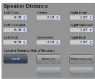
Speakers that are not available in the current configuration are not displayed. When the back surround is set to one speaker, the right back speaker is unavailable and the left back speaker is renamed center back.
Extron recommends that the SSP 7.1 Setup and Control Software is used to set speaker delays, using either of the following methods.
Two person setup
NOTE: Setting up speaker delays is easier with two people. If only one person is available, the position of the ears of the listener must be marked precisely. A pile of boxes could be used to ensure that the distances are consistently measured to the correct height. Do not try to guess ear positions, as this introduces measurement errors.
- Pick an ideal central location where all speaker output signals converge.
- Use a tape measure to measure the distance from each speaker to the convergence location. Be sure to measure to the same spot from each speaker.
NOTE: Measurements from the speaker must be to the midrange driver in a three-way speaker or from halfway between the tweeter and the woofer in a two-way speaker. Measurements to the convergence locations must be at ear height.
- Click on the Feet (ft) or Meters (m) button to select the units and enter the Speaker Distance values for each speaker (in feet or meters) in the boxes in the SSP 7.1 Setup and Control Software Speaker Delay tab. The up and down (▲) arrows increase the distance in increments corresponding to steps of 0.1 ms (0.12 feet or 0.03 meters). The software automatically selects the farthest speaker and calculates the delay time (in milliseconds) for each speaker.
These values are shown in the Calculated Delay box. The current values are shown in blue, changes (yet to be saved) are shown in orange.
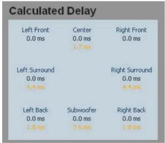
Figure 21. Calculated Delay — Values Pending
- Click the Apply button to save the changes. The new values (previously in orange) are shown in blue as the current values and there are no values displayed in orange.
To retain the original values, click Cancel instead of Apply.
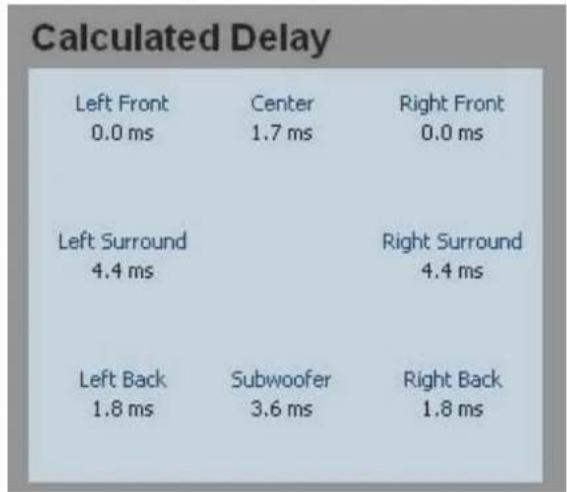
Figure 22. Calculated Delay — Values Applied
NOTE: Users who wish to calculate the delay time for themselves should follow the full procedure shown on page 94 in "Setting Speaker Delay Settings using SIS Commands."
Setup with a Real Time Analyzer (RTA) calibration tool
- Choose an ideal central location on which all speaker output signals converge.
- Place the microphone from the RTA at ear level in the convergence location.
- Play the audio source. This can be an analog source, provided by the RTA.
- Use the Test Signal Output buttons in the Testing & Output Trim Tab (see page 36) to select which speakers are tested and the order in which the speakers are tested.
- Use the RTA to measure the speaker distance (in ms) for each channel.
- In the SSP 7.1 Setup and Control Software Speaker Delay tab, select the milliseconds (ms) button and enter the values for each speaker (in ms) into the boxes. The up and down (♦) arrows increase the distance in increments of 0.1 ms.
- Repeat steps 4 to 6 until the speaker distance has been entered for all available speakers.
NOTE: The maximum allowable distance for the furthest speaker is 100 ms.
- Click the Apply button to save the changes. The new values (previously in orange, see figure 21) are shown in blue as the current values and there are no values displayed in orange (see figure 22).
To retain the original values, click Cancel instead of Apply.
Lip Sync Offset
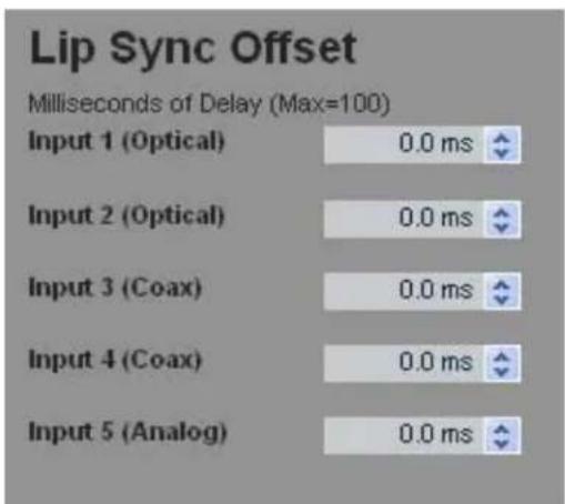
Lip sync offset compensates for a lack of coordination between the audio and the accompanying video signal. This frequently occurs if the video signal has undergone complex manipulation that can delay it several milliseconds relative to the audio signal.
Since some sources may require more manipulation than others, the lip sync offset is set for each source individually to synchronize the audio for that source with the corresponding video signal.
Enter the appropriate value in the lip sync offset box. This delay is added to every available speaker to resynchronize the video and audio signals.
Input and Output information bar
The Input and Output information bar is available from all GUI tabs and is described in detail on pages 28 and 29.
Testing & Output Trim Tab
After the Speaker Delay tab, configure the Testing & Output Trim tab.
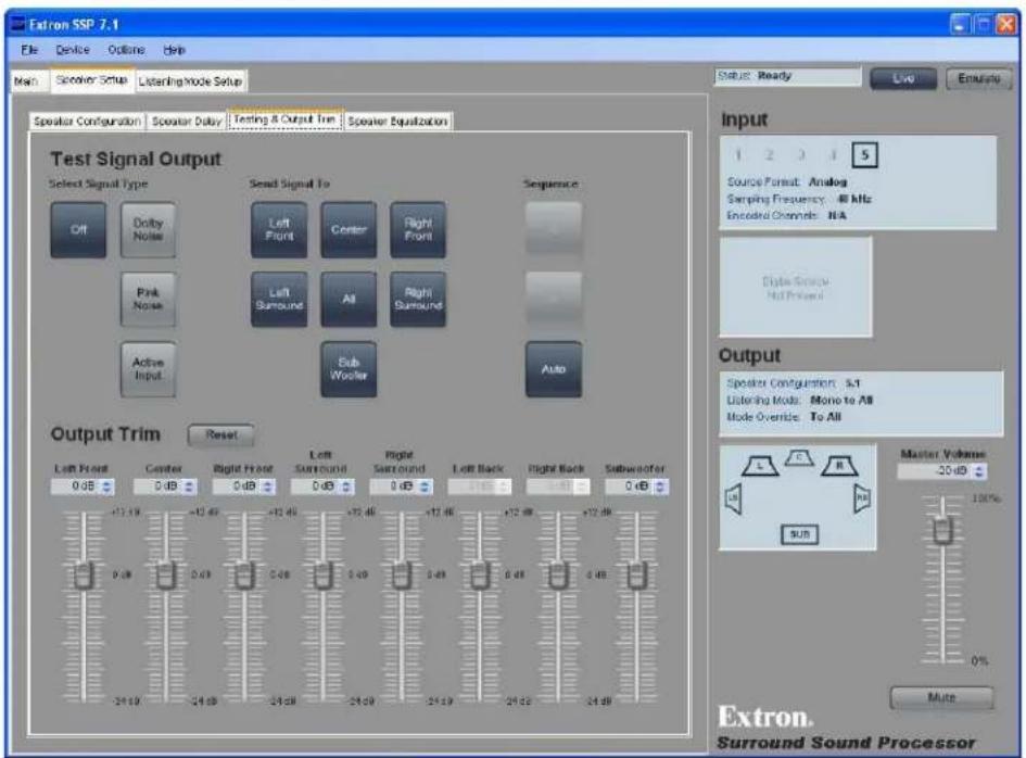
Figure 23. Testing & Output Trim Tab
Several factors can affect the sound level reaching the listener from different speakers. These factors include the distance from the speaker to the listener, slight variations between the output channels of a single amplifier, and variations between the individual speakers. Use the output trim to set the output level of each individual channel to compensate for all these variations and ensure that the sound level reaching the listener is the same from all speakers.
This tab also provides a test signal utility.
Test signals
Test signals are used during setup to calibrate the level of each channel and to ensure proper connection between the individual output channels of the SSP 7.1 and the line level input channels of an audio signal processor, a receiver with built in amplifier, or a stand alone amplifier that powers the loudspeakers.
Selecting test signal source
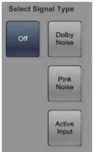
There are four test signal options (see Test Signals on page 17): Off, Dolby Noise, Pink Noise, or Active Input. They are selected from the mutually exclusive Source Signal Type buttons. By default, the test signal is Off. The Dolby Noise and Pink Noise test signals are generated by the SSP 7.1.
NOTE: The Active Input selection is normally used with an analog source on input 5. The output must be set to Mono to All.
Set the external source to Mono to All using one of these methods.
Listening Mode Preferences Tab
- Select the listening mode Preferences tab (see page 45).
- Select the input channel that is providing the test signal source (1-5).
- For whatever source format the test signal is using, select Mono to All.
- Return to the Testing & Output Trim tab and click on Active Input.
Override Preferences Tab
- Select the Override Preferences tab (see page 48) and select the input source.
- For selectable mode To All choose the override Mono to All.
- On the front panel of the SSP 7.1, use the Mode Override button to select To All
Selecting speakers to be tested
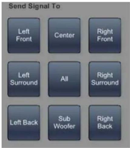
The currently available speakers are displayed in a graphics box. Speakers that are not available are not displayed.
Click on the individual speaker to select or deselect it from the list of speakers to be tested. Click on A11 to select all speakers.
NOTE: If all speakers have been selected, clicking A11 deselects all speakers.
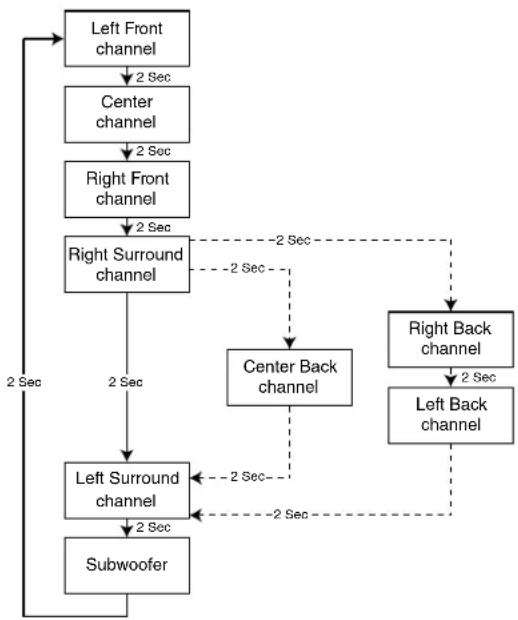
Speaker test sequence
To run an automatic test sequence
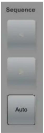
- Select the Auto button. This sends a two second test signal to each output channel in the sequence shown in the diagram at right. All other speakers are muted. The test sequence cycles through each speaker multiple times until the test signal is switched off.
- Click on Off in the Select Signal Type area to switch off the test signal and end the test sequence.
5.1 Setup 6.1 Setup 7.1 Setup
flowchart
graph TD
    A["Left Front channel"] -->|2 Sec| B["Center channel"]
    B -->|2 Sec| C["Right Front channel"]
    C -->|2 Sec| D["Right Surround channel"]
    D -->|2 Sec| E["Left Surround channel"]
    E -->|2 Sec| F["Subwoofer"]
    D -.->|2 Sec| G["Center Back channel"]
    G --> H["Right Back channel"]
    H -->|2 Sec| I["Left Back channel"]
    I -.->|2 Sec| E
To test the speakers manually:
- Click Auto to deselect it.
- Click the forward (>) or back (<) buttons to move forward or backward through the sequence shown in the diagram below.
- Click Off in the Select Signal Type area to switch off the test signal and end the test sequence.
Output Trim
The Output Trim sliders control the audio signal level for each individual channel output. Only channels that are enabled in the current speaker configuration are available; the others are displayed but cannot be adjusted. Output trim is adjustable from -24 dB to +12 dB. The current value for each output channel is shown in the text box.
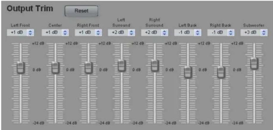
Figure 24. Output Trim
NOTE: The maximum output volume is tied to the output trim. When an output trim value is higher than 0 dB, the highest possible output volume is reduced by that amount. For example, if the highest output trim for any channel is set to +5 dB, the maximum output volume is -5 dB.
Extron recommends using a Sound Pressure Level (SPL) meter to set the output trim for each speaker:
- Set up the SPL meter at the sweet spot in the room.
- Send a test signal, generated as described in Test Signals on page 36, to each individual speaker in turn. Extron recommends using the Dolby Noise signal and sending the signals to the speakers manually.
NOTE: The test signal should have a sound level at least 20 - 30 dB above ambient levels.
- Measure and write down the sound pressure for each speaker.
- To avoid decreasing the maximum output volume (see the note above), Extron recommends that you use the speaker with the lowest SPL reading as the zero reference point. Then attenuate all the other speakers by the required amount to balance all speakers.
In the example below, the SPL readings for five channels are given in column 2. Channel 4 has the lowest reading and is used as the zero reference point. The difference between each speaker and the zero reference is calculated in column 3. This is the adjustment that must be made to the output trim for that channel.
| Channel SPL | Reading Output | Trim Adjustment (dB) |
| 1 75 -1 | ||
| 2 76 -2 | ||
| 3 79 -5 | ||
| 4 74 0 | (zero reference channel) | |
| 5 77 -3 |
- Use any of these methods to adjust the output trim for each speaker.
• Grab and drag the slider bar to adjust output trim in 1 dB increments.
- Click on one of the output trim slider controls to activate it and use the up and down arrows beside the text box to adjust it in 1 dB increments.
- Click on one of the output trim slider controls to activate it and use the up and down keys on the keyboard to adjust it in 1 dB increments.
- Click on one of the output trim slider controls to activate it and use the page up and page down keys on the keyboard to adjust it in 5 dB increments.
- Highlight the value in the text box, type a number (omit the dB), and press Enter on the keyboard.
The Reset button returns the output trim values for all speakers to the default value (0 dB).
Input and Output information bar
The Input and Output information bar is available from all GUI tabs and is described in detail on pages 28 and 29.
Speaker Equalization Tab
After the Testing & Output Trim tab, configure the Speaker Equalization tab.
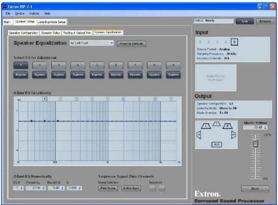
Figure 25. Speaker Equalization Tab
The Speaker Equalization tab provides nine parametric EQs for each output channel. The default frequency values correspond to a nine-band graphic equalizer, which provides a starting point for refining the output signal from each speaker channel.
All the properties of the SSP 7.1 parametric EQs can be defined by the user.
Speaker selection
Select the speaker to be configured from the drop-down menu.

Figure 26. Speaker Selection Menu
EQ selection
Select the EQ to be adjusted (1-9) by pressing the desired numbered button and deactivating the corresponding Bypass button. The numbered buttons are a mutually exclusive set (only one button can be activated at a time). By default all EQs are bypassed.

Figure 27. EQ Band Selection Buttons
When an EQ has been selected, it can be adjusted in the graphic box or the text boxes at the bottom of the screen.
When the bypass is activated for an EQ, the values are saved for future use but do not act on the signal path. When the bypass is deactivated, changes made to that EQ contribute to the composite graph that is displayed. The graph shows how the activated EQs combine to affect the signal path in the current setup.
Right click the EQ number to bring up a context sensitive menu (see figure 27). Select Reset to return to default values for the currently selected EQ only, or select Reset A11 to return to default values for all EQs for the selected speaker channel.
Adjust EQ graphically
When an EQ is selected (see "EQ selection" on page 41) the EQ Graph displays a composite curve showing the individual EQ that is being configured with three parameter adjustment handles. A vertical white line marks the position of the handle (frequency) currently being adjusted.
Click and drag the EQ number (highlighted at the top of the graph) to adjust the horizontal position of the handle. Click and drag the center handle up or down to adjust the boost or cut level (in dB).
Click either of the outer handles to adjust the bandwidth, expressed as a Q value (frequency divided by bandwidth). If either of these outer handles moves, the other outer handle moves in the opposite direction to maintain a symmetry about the center handle.
NOTE: When values are altered in the graphics display, the numeric values in the "Adjust EQ Numerically" section (see next page) are updated to reflect the changes.
In the example below, the adjustment handles for EQ 3 are shown. The selected EQ is highlighted at the top of the graph.
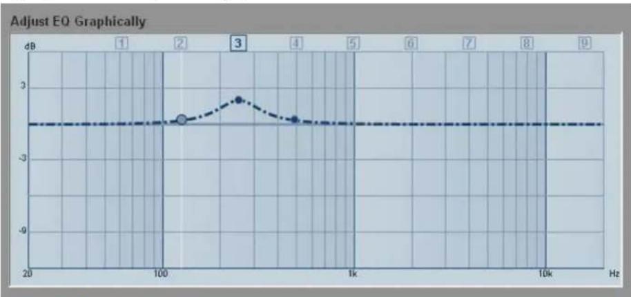
line
| Frequency (Hz) | Value (dB) | | -------------- | ---------- | | 100 | -2.5 | | 200 | -2.0 | | 300 | -1.5 | | 400 | -2.8 | | 500 | -2.5 | | 600 | -2.5 | | 700 | -2.5 | | 800 | -2.5 | | 900 | -2.5 |Figure 28. Graph for EQ Band 3
In the graph below, EQs 1, 2, 3, and 4 have been adjusted. The effects of adjusting EQs 2, 3, and 4 can be seen by the deviation from the horizontal line. The effect of adjusting EQ 1 is not seen because the bypass button for that EQ is still activated and adjustments to EQ 1 are not used to process the audio signal. The numbers of the EQs contributing to the graph (2, 3, and 4, but not 1) are shown in white against a blue background at the top of the graph.
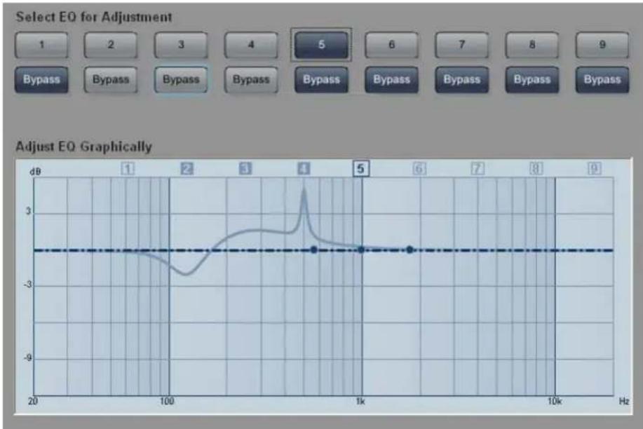
line
| Frequency (Hz) | Adjusted EQ (dB) | | -------------- | ---------------- | | 20 | -2.5 | | 100 | -2.5 | | 1k | -2.5 | | 10k | -2.5 |Figure 29. Graph After Bands 2, 3, and 4 Have Been Adjusted
Adjust EQ numerically
These four fields control the parameters that can also be adjusted in the graph.
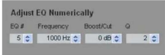
Figure 30. Menus for Adjusting EQ Numerically
EQ# — selects which EQ is adjusted.
Frequency — adjusts the frequency of the center handle on the graph.
Boost/Cut — adjusts the amount of amplification or attenuation applied to that particular EQ.
Q — adjusts the bandwidth to which the boost or cut is applied. As the Q value increases, the bandwidth becomes narrower.
NOTE: When values are altered in the Adjust EQ Numerically fields, the graphic display is updated to reflect the changes.
Test Signals
Use the Test Signals section of the screen to select Pink Noise or the Active Input signal as the sound source. Use the sequence arrows to apply the test signal to the appropriate output channel.
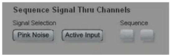
Input and Output information bar
The Input and Output information bar is available from all GUI tabs and is described in detail on pages 28 and 29.
Listening Mode Setup Tab
After completing the Speaker Setup tab, the final tab is Listening Mode Setup. This tab provides access to three second-level tabs (Preferences, Override Preferences, and Dolby, DTS, and Mono Settings).
For each combination of source format and speaker configuration, the SSP 7.1 has a default listening mode. However, this cannot take into account the characteristics of the room or the personal preferences of the listener. The Listening Mode Setup tab allows users to customize their preferences for each input channel and for each combination of source format and speaker configuration.
Preferences Tab
The Listening Mode Setup tab opens at the Preferences tab.
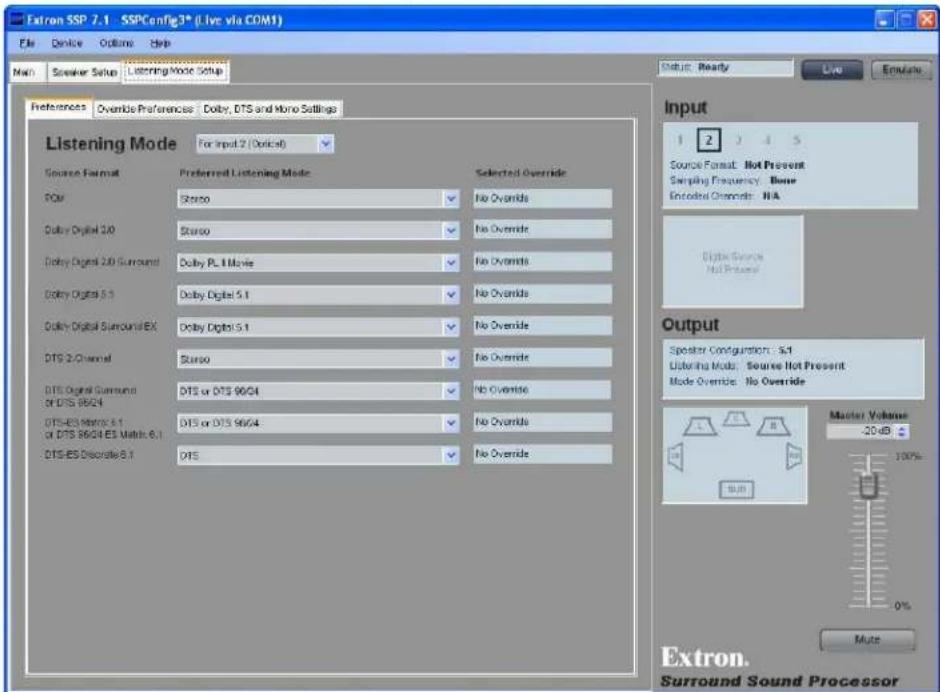
Figure 31. Preferences Tab
Input channel
Select the input channel to be configured from the drop-down menu.
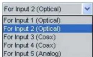
Listening mode selection
Use the drop-down menus to select the preferred listening mode to be associated with each source format. A full list of all options can be found in "Source Formats and Listening Modes with Different Speaker Setups" on page 75.
The available selections are dynamically populated so that they represent only the values that are available for the current speaker configuration. When input 5 is selected, the only Source Format available is Analog (see figure 32 below). When a digital input is selected, a full range of digital source formats is available (see figure 33 below).
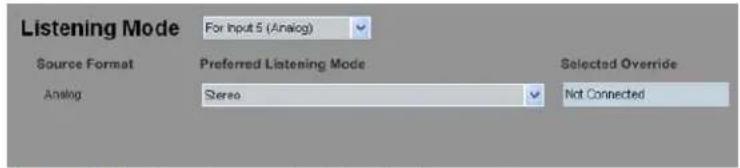
Figure 32. Listening Mode Selection (Input 5)
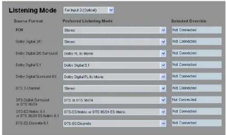
Figure 33. Listening Mode Selection (Input 2)
The default listening mode for each source format is initially shown. The drop-down menu offers all the listening modes that are available for each source format per each speaker configuration.
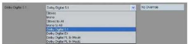
Figure 34. Listening Mode Menu
NOTE: When a listening mode that sums the left and right channels is applied, clipping is possible on the summed channels. Instances of this include applying Mono, Mono to All, or PL II/IIx listening modes to a stereo source.
The Selected Override text matches the current state of the front panel Mode Override LEDs.
No Mode Override selected
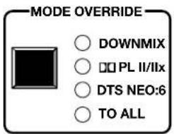

Downmix selected
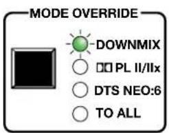

Dolby PL II/IIx selected
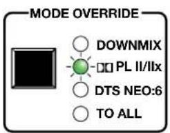

DTS Neo:6 selected
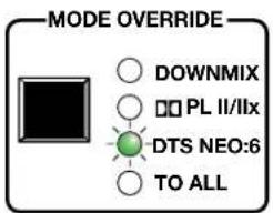

To All selected
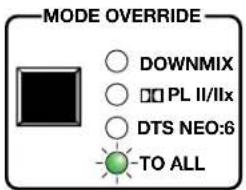

Figure 35. Selected Override Matches Front Panel LEDs
When there is no source, the Selected Override box reads "No Override."
Input and Output information bar
The Input and Output information bar is available from all GUI tabs and is described in detail on pages 28 and 29.
Override Preferences Tab
Listening mode override
After selecting the listening mode, click on the Override Preferences tab to adjust the mode override options. These preferences are applied when the front panel override option is engaged and allow further refinement of the front panel override. The available options for each mode override group are listed under the appropriate drop-down menu.
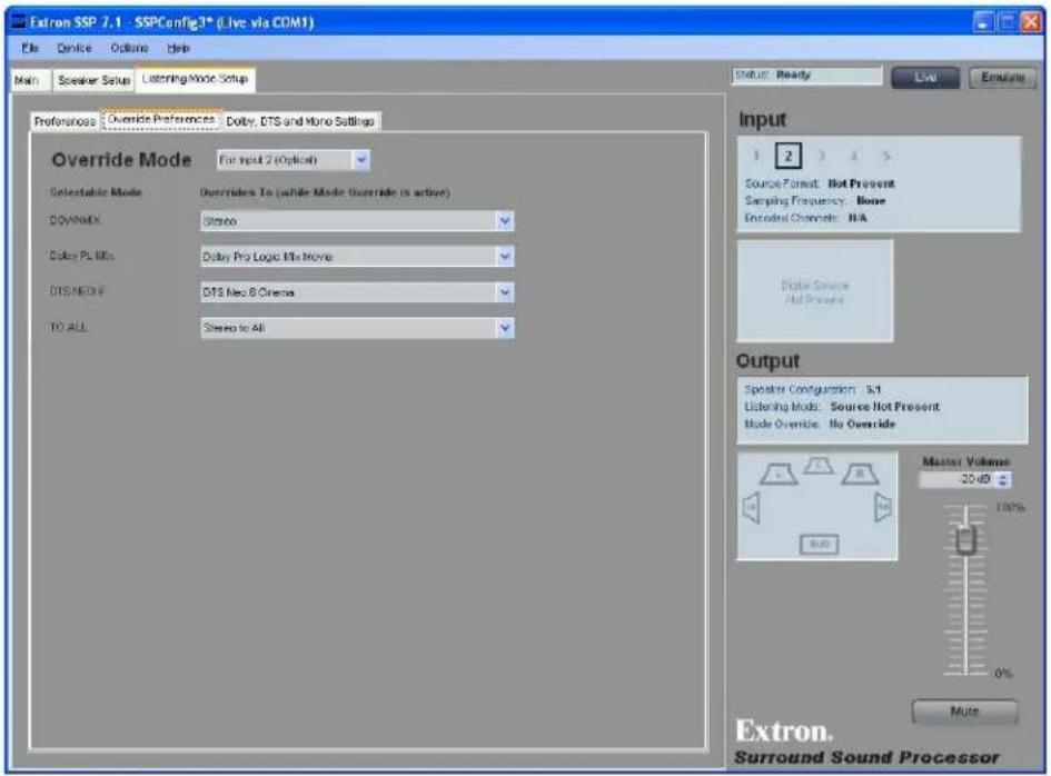
Figure 36. Listening Mode — Override Preferences
The table below shows the Mode Override options that are available from the drop-down menus for each selectable mode.
Selectable Mode Listening Mode Options
| Downmix | Stereo (default)Mono |
| PL II/IIx | Dolby Pro Logic II/IIx Movie (default)Dolby Pro Logic II/IIx Music |
| DTS NEO:6 | DTS Neo:6 Cinema (default)DTS Neo:6 Music |
| TO ALL | Stereo to All (default)Mono to All |
More information can be found in the Reference Material section about source formats (page 61), listening modes (page 66), mode override (page 7), and listening modes that are available for each source format (page 75).
Input and Output information bar
The Input and Output information bar is available from all GUI tabs and is described in detail on pages 28 and 29.
Dolby, DTS and Mono Settings Tab
After configuring Override Preferences, click the Dolby, DTS and Mono Settings tab.
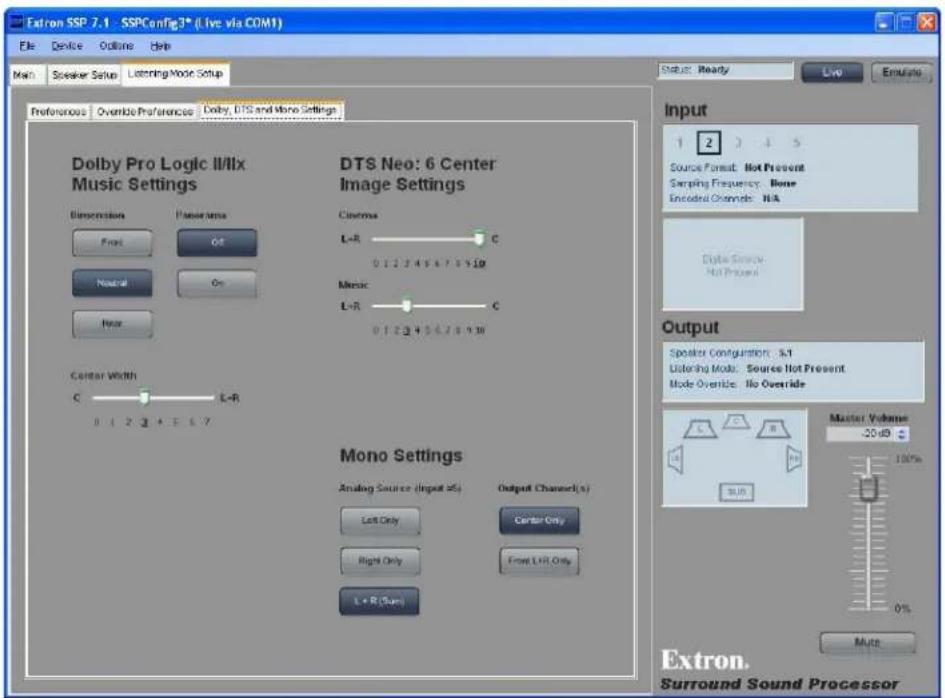
Figure 37. Dolby, DTS and Mono Settings Tab
This tab allows advanced adjustments to the settings for Dolby ProLogic II/IIx Music, DTS Neo:6, and how mono signals are received and output by the SSP 7.1.
Dolby Pro Logic II/IIx Music Settings
The Dolby Pro Logic II/IIx Music listening mode is used for listening to any stereo music recordings. More information about this listening mode can be found on page 68 of the Reference material. These controls adjust global settings for the listening mode, to tailor the sound to individual listening tastes.
Dimension control
These buttons allow the user to choose Front, Neutral, or Rear (the default is Neutral). See page 68 for more information about Dimension Control.
Panorama control
These buttons allow the user to switch the Panorama settings On or Off (the default is Off). See page 68 for more information about Panorama Control.
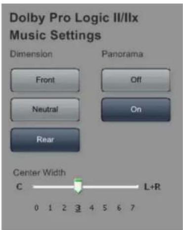
Center Width control
This sliding bar adjusts the Center Width control in the range 0-7. When the control is set to 0, the sound comes from the front center speaker. At 7, the sound comes from the front right and left speakers. The default setting is 3 (bold and underlined). See page 68 for more information about Center Width control.
DTS Neo:6 settings
Center Image Settings
These controls set the center image for DTS Neo:6 Cinema and DTS Neo:6 Music listening modes. More information about this listening mode is found on page 69.
The sliding bars adjust the center image control settings:
• DTS Neo:6 Cinema: 0 - 10 (the default is 10)
• DTS Neo:6 Music: 0 - 10 (the default is 3)
Setting the control to 0 creates the effect of spreading out the audio signal across the front speakers. Setting the control to 10 creates the effect of centralizing the audio signal.
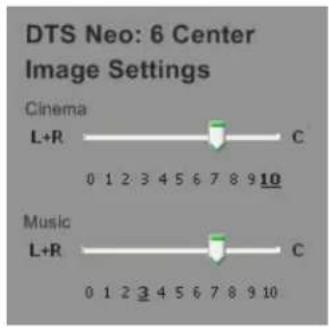
See page 69 for more information about Center Image control.
Mono Settings
Two advanced configurations apply only to mono sources or outputs.
Analog Source (applies to Input 5 only)
A mono signal may be input as left channel only, right channel only, or the sum of left and right channels (both channels input identical mono signals). These controls allow the user to decide whether the Left Only, Right Only, or L+R (Sum) summed input becomes the source for the mono decoding mode. The default is L + R (Sum).
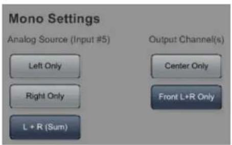
Output Channel(s)
These buttons let the user select whether mono signals are output to the center channel (Center Only) or a dual mono signal is sent to the right and left front channels (Front L+R Only). The default is Center Only.
Input and Output information bar
The Input and Output information bar is available from all GUI tabs and is described in detail on pages 28 and 29.
Drop-down Menus
The menu bar at the top of the window provides additional tools and options. The four top-level headings are File, Device, Options, and Help (see figure at right).
File
The File menu options allow you to save changes made to the configuration of the SSP 7.1, whether you are running the software in Live or Emulate mode. The current configuration can be saved as an *.esp file, which can be opened, further modified, saved, or saved by a different name. The File menu has five options.
New — If the software is in Emulate mode, you can save the configuration changes you have made to a new file by clicking on New. This creates a new file with the default settings that can be saved in any directory on your network.
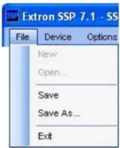
Open — Opens an existing file. The current settings of the SSP 7.1 are replaced by the values in the file being opened.
Save — If the file that is currently being modified in Emulate mode has already been named and saved, this option saves any updates to the same file.
Save As — If the file that is currently being modified in Emulate mode has not been named, this allows you to name the file, place it in any directory on your network, and save it.
Exit — Clicking on Exit shuts down the program.
Changes to the configuration of the SSP 7.1 made in Live mode are saved as they are made. Exiting the program after a Live mode session, leaves all changes from that session in effect.
To restore all values to factory defaults, select the Reset... option in the Device menu on the following page.
Device
The Device menu has eight options.
Connect... (F5) — In Emulate mode, the option Connect... is available, allowing the user to switch to Live mode and open a direct connection to the SSP 7.1 unit. You may also use the F5 keyboard button to switch from Emulate to Live. The Connect... option is not available in Live mode.
Disconnect (F6) — In Live mode, the option Disconnect is available, allowing the user to close the connection to the SSP 7.1 unit and switch to Emulate mode. You may also use the F6 keyboard button to switch from Live to Emulate. The Disconnect option is not available in Emulate mode.
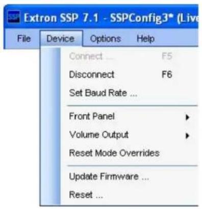
For more information about Live and Emulate modes, see page 23.
Set Baud Rate... — This opens the Device Settings dialog box, which allows the user to change the baud rate of the connection between the computer and the SSP 7.1. Changing the baud rate closes the connection between the computer and the SSP 7.1. The control program then attempts to reconnect to the sound processor at the new baud rate.
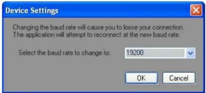
Figure 38. Device Settings Dialog Box
Front Panel — When the Locked option is selected, the front panel cannot be used to perform any functions from the front panel

(except unlocking the front panel); when the Unlocked option is selected, the functions can again be controlled from the front panel.
Volume Output — The volume of the audio output through all channels can be set globally using these sub-menu options to choose either Fixed or Variable (the default value).
The Fixed option sets the volume to full output with no attenuation. The volume cannot be adjusted through the front panel knob or by using the

SSP 7.1 Setup and Control Software or SIS commands. All the Output Channel Trim Levels (see page 39) are fixed at the values they had immediately before the Volume Output was set to Fixed.
The Variable option allows the volume to be attenuated through the front panel knob, the SSP 7.1 Setup and Control Software, or by SIS commands.
Reset Mode Overrides — This option removes any mode overrides that have been set using the front panel Mode Override button.
Update Firmware... — Launches the Firmware Loader application. For information about how to update the SSP 7.1 firmware, see "Firmware Updates" on page 56.
NOTE: The Firmware Loader application must be installed on your PC for this option to work.
Reset... — The Factory Reset option undoes any user changes and resets all values to the factory defaults.
Options
The Options menu has two choices.
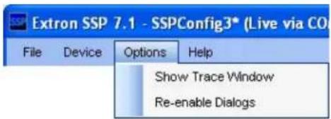
Show Trace Window — The Show Trace Window command opens the Trace Window (see figure at right). This window displays all commands and data sent from the computer to the SSP 7.1 unit in the upper pane, and all responses and data sent from the SSP 7.1 unit to the computer in the lower pane. These data are useful to qualified service personnel for some troubleshooting situations.
The Clear Data button clears data from both panes.
The Close button, shuts down the window. Data are still being sent between the computer and the sound processor and can still be viewed by reopening the window.
![Trace Window Data Sent Sync Sent: \eX4*3SSP\v Sync Sent: \eX4*6SSP\v Sync Sent: \eX4*7SSP\v Sync Sent: \eX4*8SSP\v Sync Sent: \eX4*9SSP\v Sync Sent: \eX4*10SSP\v Sync Sent: \eX5*1SSP\v Data Received Read: SspL02*00*00 [OnPush]SspL02*00*00\r\n Read: SspL02*00*00 [OnPush]SspQ02*00*00\r\n Read: SspQ02*00*00 [OnPush]SrcFormat 00 Sampling 00 EnChan 00\r\n Read: SrcFormat 00 Sampling 00 EnChan 00 Clear Data Close](/content/2026/05/798009/images/35c8894dc87f3956ca7c6c8ed21c9f25464d770db015f174fc58072e7dda2e0d.jpg)
Re-enable Dialogs — Certain warning dialog boxes, such as the one shown at right, have a check box that stop them from being shown again. If you discover that it is helpful to receive the warning, selecting Re-enable Dialogs restores all the dialog boxes that had been blocked.
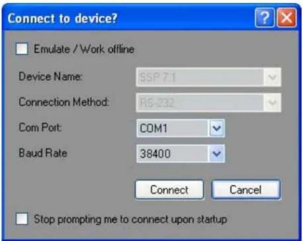
SSP 7.1 • Setup and Control Software 53
Help
The Help menu has four options.

About This Software — Click About This Software to open a flash screen with information about the SSP 7.1, including the software version installed (Version x.x.x.xx) and the firmware version installed (Firmware Version: x.xx.xxxx).
To close the screen, click on OK or the X in the top right corner.
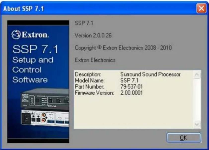
Figure 39. About SSP 7.1 Screen
SSP 7.1 Help (F1) — Click the SSP 7.1 Help option or press the F1 key on the keyboard while running the SSP 7.1 Setup and Control Software to open the help file. For more information about the SSP 7.1 Setup and Control Software help file, see page 55.
Search Help — The Search Help option opens the help file with a search box, which allows the user to find a specific topic in the file.
Go to Extron.com — Click Go to Extron.com to open your default web browser at the Extron home page (www.extron.com).
SSP 7.1 Setup and Control Software Help File
Information about the SSP 7.1 Setup and Control Software can also be found in the associated help file. Click the SSP 7.1 Help option in the Help menu or press the F1 key when the program is being used to open the help file.
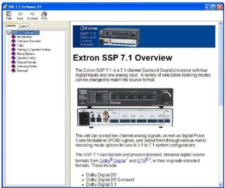
Figure 40. SSP 7.1 Setup and Control Software Help File — Contents
Use the Table of Contents in the left panel to find and navigate to a topic.
You can also click on the Search tab or select the Search Help option from the Help menu of the control software. This opens the help file search tool.
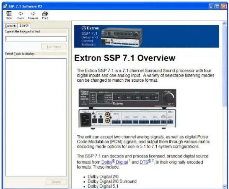
Figure 41. SSP 7.1 Setup and Control Software Help File — Search
Firmware Updates
NOTES: • Ensure that you are using the latest versions of the SSP 7.1 Setup and Control Software and firmware. To update firmware, install the Extron Firmware Loader on your PC. All three programs are available from the Extron Web site.
- To download software from the Extron Web site, click on the Download tab and select either the Firmware or Software option in the left sidebar. Navigate to the appropriate program and click Download. Follow the on-screen instructions to install the program.
Upgrade the SSP 7.1 firmware as follows:
- Turn off or disconnect all audio inputs before updating the firmware.
ATTENTION: Updating the firmware while the unit is still accepting active audio inputs may cause the firmware update to freeze.
- Power on the SSP 7.1 and a computer.
- Connect the computer to the SSP 7.1 through the rear panel RS-232 captive screw connectors.
- If necessary, install the Extron Firmware Loader utility. This is on the software disk provided or can be downloaded from the Extron Web site (www.extron.com).
- From the same site, download the firmware for the SSP 7.1.
- To download the firmware for the SSP 7.1, click on the Download tab at the top of the Extron home page and then click Firmware in the sidebar to the left.
- Navigate to the firmware for the SSP 7.1 and click on Download.
- In the dialog box, click Save.
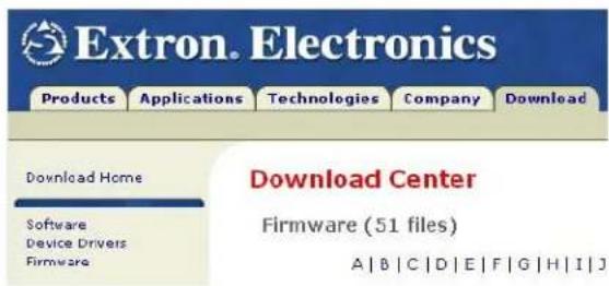
NOTE: Make a note of the folder where you save the firmware.
- Open the SSP 7.1 Setup and Control software and click on the Update Firmware option in the Device menu. The Firmware Loader Add Device... dialog box opens.
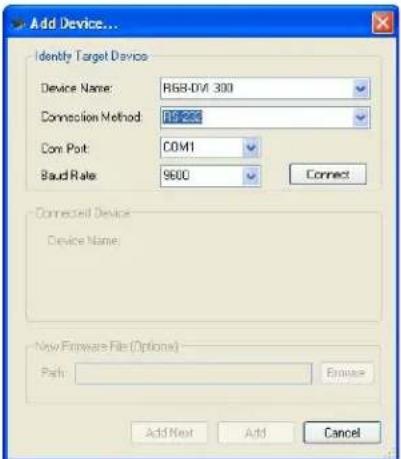
Figure 42. Add Device... Dialog Box
- Select SSP 7.1 from the device list, RS-232 as the connection method, select the correct com port and baud rate (default rate is 38400) and click the Connect button. The PC connects to the SSP 7.1.
When the connection is made, the name of the device appears, with a green check mark, in the Connected Device box.
- Click the Browse button and navigate to the folder where the firmware file was saved (see step 8).
- Click the Add button. The Add Device... box closes to reveal the main Firmware Loader window.
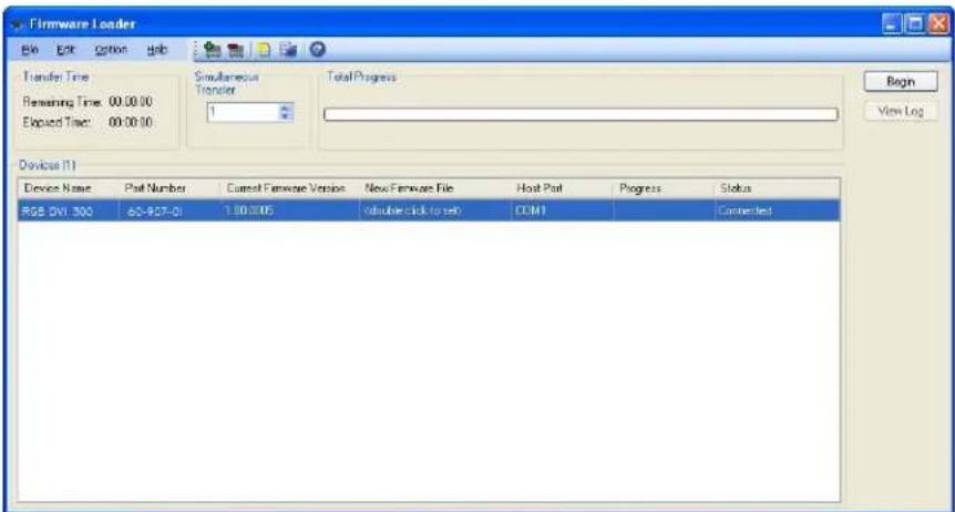
Figure 43. Firmware Loader Main Window
- Click on the Begin button.
- When the transfer is complete, the Total Progress box reads 100% and the entry in the Status column reads Complete.
Specifications, Parts, and Accessories
This section provides information about:
- Specifications
- Included Parts
- Optional Accessories
Specifications
Audio
Gain.... Unbalanced output: -6 dB; balanced output: 0 dB, when volume is set to 0 dB gain.
Frequency response.... 20 Hz to 20 kHz, ±0.2 dB
Subwoofer frequency response..... 4 Hz to 250 Hz, ±3 dB
THD + Noise.... <0.03% @ 1 kHz, at maximum output level
S/N..... >100 dB, 20 Hz to 20 kHz, unweighted
Stereo channel separation ...... Analog input only: >90 dB @ 1 kHz
CMRR Analog input only: >75 dB (typical) @ 1 kHz
Bass adjustment .... ±10 dB @ 90 Hz
Treble adjustment.... ±10 dB @ 7500 Hz
Volume control.... - 100 dB to 0 dB
Bass management crossover frequencies
40 Hz to 250 Hz
Audio input — analog
Number/signal type.... 1 analog stereo/mono, balanced/unbalanced
Listening modes.... Stereo, stereo to all, mono, mono to all, Dolby® Pro Logic®. Dolby Pro Logic II Movie/Music, Dolby Pro Logic IIX Movie/Music, DTS™ Neo:6 Cinema/Music
Connector.... (1) 3.5 mm captive screw connector, 5 pole
Impedance .... >10k ohms balanced/unbalanced, DC coupled
Nominal level ....+4 dBu (1.23 Vrms) balanced or -10 dBV (316 mVrms) unbalanced
Maximum level.... +21 dBu (balanced/unbalanced)
Input gain adjustment.... 0 dB to +24 dB (default = 0 dB), adjustable via RS-232 or front panel
NOTE: 0 dBu = 0.775 Vrms, 0 dBV = 1 Vrms, 0 dBV ≈ 2 dBu
Audio input — digital
Number/signal type 4 S/PDIF (2 optical, 2 coaxial)
Source formats.... PCM, Dolby Digital 2/0, Dolby Digital 2/0 Surround, Dolby Digital 5.1, Dolby Digital Surround EX, DTS 2-channel, DTS Digital Surround, DTS-ES Matrix 6.1, DTS-ES Discrete 6.1, DTS 96/24, DTS 96/24 ES Matrix 6.1
Listening modes.... Stereo, stereo to all, mono, mono to all, Dolby Digital 5.1, Dolby Digital EX, Dolby Pro Logic, Dolby Pro Logic II Movie/Music, Dolby Pro Logic IIX Movie/Music, Dolby Digital Pro Logic IIX Movie/Music, DTS, DTS 96/24, DTS-ES Matrix, DTS 96/24 ES Matrix, DTS-ES Discrete, DTS Neo:6 Cinema/Music, DTS + Dolby EX, DTS 96/24 + Dolby EX, DTS + Dolby Pro Logic IIX Movie/Music, DTS 96/24 + Dolby Pro Logic IIX Movie/Music
Connectors 2 TOSLINK™ fiber optic connectors 2 RCA jacks
Audio output
Number/signal type .... 8 balanced/unbalanced, for left and right front, left and right sides, left and right back, center, and subwoofer output
Connectors ..... (3) 3.5 mm captive screw connectors, 6 pole
(2) 3.5 mm captive screw connectors, 3 pole
Impedance 50 ohms unbalanced, 100 ohms balanced
Gain error ±0.2 dB channel to channel
Maximum level (Hi-Z).... >+21 dBu balanced or >+15 dBu unbalanced at 0.03% THD+N
Output level range per channel ..... -24 dB to +12 dB
D/A conversion.... 24 bit, 96 kHz
Control/remote — audio processor
Serial host control port.... 1 bidirectional RS-232 front panel 2.5 mm mini stereo jack 1 bidirectional RS-232 rear panel 3.5 mm captive screw connector, 3 pole
Baud rate and protocol.... 9600, 19200, 38400 (default), 115200 baud (adjustable); 8 data bits, 1 stop bit, no parity
Pin configurations ...... Mini stereo jack: tip = Tx, ring = Rx, sleeve = GND
Captive screw connector: pin 1 = Tx, 2 = Rx, 3 = GND
Program control .... Extron control/configuration program for Windows®
Extron Simple Instruction Set ^™ (SIS ^™ )
General
Power 100 VAC to 240 VAC, 50-60 Hz, 12 watts, internal
Temperature/humidity ...... Storage: -40 to +158 °F (-40 to +70 °C) / 10% to 90%, noncondensing
Operating: +32 to +122 °F (0 to +50 °C) / 10% to 90%, noncondensing
Cooling...... Convection, no vents
Mounting
Rack mount .... Yes, with optional 1U rack shelf
Furniture mount .... Yes, with optional under-desk mounting kit
Enclosure type.... Metal
Enclosure dimensions 1.7" H x 8.75" W x 6.0" D (1U high, half rack wide)
(4.3 cm H x 22.2 cm W x 15.2 cm D)
(Depth excludes connectors and knob.)
Product weight.... 1.3 lbs (0.6 kg)
Shipping weight.... 3 lbs (2 kg)
Vibration.... ISTA 1A in carton (International Safe Transit Association)
Regulatory compliance
Safety CE, c-UL, UL
EMI/EMC CE, C-tick, FCC Class B, ICES, VCCI
Environmental...... Complies with the appropriate requirements of RoHS and WEEE.
MTBF 30,000 hours
Warranty 3 years parts and labor
NOTES: • All nominal levels are at ±10%
- Specifications are subject to change without notice.
Included Parts
| Description Part Number | |
| (1) SSP 7.1 60-842-01 | |
| (4) Rubber feet (not attached) | |
| (1) 5-pole, 3.5 mm captive screw plug | |
| (9) 3-pole, 3.5 mm captive screw plug | |
| Extron Control Software disk | |
| Tweeker | |
| (1) IEC power cable | |
| SSP 7.1 Setup Guide |
Optional Accessories
| Description Part Number | |
| RSU 129 (1U 9.5 inch deep rack shelf kit) 60-190-01 | |
| RSB 129 (1U 9.5 inch deep basic rack shelf) 60-604-01 | |
| RSU 126 (1U 6 inch deep rack shelf kit) 60-190-10 | |
| RSB 126 (1U 6 inch deep basic rack shelf) 60-604-10 | |
| MBU 125 (under desk mounting kit) 70-077-01 | |
| CSR 6 (5-pin captive screw to RCA female audio adapter) 26-575-01 |
Reference Material
This section provides information about Source Formats and Listening Mode Options and Usage.
Source Formats
Surround Channel Information
Surround channel information is written in the following format:
A/B.C (For example 3/2.1)
A represents the number of front channels (maximum 3: front right, front left, and center). If A is 1, the source format has a mono encoded signal for playback through the center channel. If A is 2, the source format encodes two discrete channels for stereo playback through the front right and front left channels. If A is 3, there is a discrete encoded signal for all three front speakers.
B represents the number of surround channels (maximum 3: surround right, surround left, and back). If B is 1, the source format has a mono encoded signal for playback as dual mono through the surround right and surround left channels. If B is 2, the source format encodes two discrete channels for stereo playback through the surround right and surround left channels. If B is 3, there is a discrete encoded signal for all three speakers, including the back speaker.
NOTE: There is no "4" option because, while the SSP 7.1 can output up to eight full bandwidth channels, there are presently no source formats that can pass digital bit stream audio information containing 7.1 discrete encoded channels through S/PDIF connections, which is the connection type that the SSP 7.1 supports.
C represents the presence or absence of LFE (1 = present; 0 = none or absent). This is the discrete bass information, normally designated for use with the subwoofer channel, but may be mixed with other channels in the absence of a subwoofer.
| Encoded Channels Minimum RequiredOutput SpeakerConfiguration | |
| 1/0.0 or 2/0.0 2.0 | |
| 1/0.1 or 2/0.1 2.1 | |
| 2/1.0 5.0 | |
| 2/1.1 5.1 | |
| 2/2.0 5.0 | |
| 2/2.1 5.1 | |
| 2/3.0 6.0 | |
| 2/3.1 6.1 | |
| 3/0.0 3.0 | |
| 3/0.1 3.1 | |
| 3/1.0 5.0 | |
| 3/1.1 5.1 | |
| 3/2.0 5.0 | |
| 3/2.1 5.1 | |
| 3/3.0 6.0 | |
| 3/3.1 6.1 | |
NOTES: • The minimum allowable configuration of the SSP 7.1 is 2.0 because the left and right front speakers are always on. In the absence of a center channel, 1/0.0 and 1/0.1 encoded channels are output equally to both front channels.
- 7.0, 7.0 (with no center channel), 7.1, and 7.1 (with no center channel) are valid output speaker configurations. However, standard DVD audio sources cannot be encoded as 2/4.0, 2/4.1, 3/4.0, or 3/4.1.
- Blu-Ray DVD players output audio from Blu-Ray DVDs, which can carry 7.1 or more discrete encoded channels. However, that audio can be transmitted only via the HDMI output and can be processed only by an AV receiver that supports HDMI connections. The Blu-Ray player should support S/PDIF connections that output Dolby Digital and DTS multichannel source formats, which are also embedded in the Blu-Ray DVD and can be used to feed into the SSP 7.1 via a TOSLINK or coaxial connection.
Dolby Digital Source Formats (DD)
Inputs 1-4 only
Dolby Digital 5.1
(3/2.1, 3/2, 3/1.1, 3/1, 3/0, 3/0.1, 2/2.1, 2/2, 2/1.1, 2/1, 2/0.1, 2/0, 1/0.1, or 1/0)
Dolby Digital is a flexible, discrete, digital technology for carrying audio. Dolby Digital is a 5.1-channel surround sound format and is the standard for DVD video.
Dolby Digital features up to five discrete channels (front center, front left, front right, surround left, and surround right), which gives it the "5" designation. Each of the channels is full frequency with respect to human hearing (20 Hz to 20kHz). There is an additional channel reserved for low frequency effects (LFE), which is usually reserved for the subwoofer speaker(s) or other speakers capable of reproducing low frequencies (3 - 120 Hz). This gives the ".1" designation, since the sixth channel is not full frequency.
Although referred to as 5.1, it includes a variety of combinations, including 1.0, 2.0, 2.1, 3.0, 3.1, 4.0, 4.1, 5.0, and 5.1.
Dolby Digital 2/0
(2/0)
Dolby Digital 2/0 is a specific stereo format encoded by Dolby Digital technology. Encoded information is intended primarily for playback by the front left and front right speakers. TV broadcasts or DVD movie commentaries often have audio tracks encoded using this format.
When the SSP 7.1 detects this source format, both the ☐ and 2-CH LEDs are lit.
Dolby Digital 2/0 Surround
(2/0)
Dolby Digital 2/0 Surround is the consumer version of the original Dolby multichannel analog film sound format. Left, center, right, and mono surround are matrix-encoded onto two audio tracks. These two tracks can be decoded by Dolby Pro Logic to recreate the original four-channel sound. This source format is typically used for digital television broadcast signals and older, remastered, movies.
When the SSP 7.1 detects this source format, both the D and 2-CH LEDs are lit.
Dolby Digital Surround EX
(3/2.1)
Dolby Digital Surround EX is a commercial format that reproduces the center channel information through speakers placed directly behind the listener.
The back surround information is matrix-encoded onto the right and left surround channels of conventional Dolby 5.1 formats. If there is no back channel speaker, the information for that channel is played through the right and left surround speakers.
DTS Source Formats (DTS)
Inputs 1-4 only
DTS 2-Channel
(2/0)
DTS 2-Channel is a specific DTS encoded stereo format. Material encoded in this source format is typically found in DTS-HD Blue Ray DVDs and is primarily intended for playback by the left and right front speakers. When this source format is present, both the DTS and the 2-CH LEDs light.
DTS Digital Surround
(3/2.1, 3/2, 3/1.1, 3/1, 3/0, 3/0.1, 2/2.1, 2/2, 2/1.1, 2/1, 2/0.1, 2/0, 1/0.1, or 1/0)
DTS Digital Surround is a 5.1-channel surround sound format similar to Dolby Digital 5.1. As with the Dolby format, there are five full frequency channels (front center, front left, front right, surround left, and surround right) and an additional LFE channel.
DTS 96/24
(3/2.1, 3/2, 3/1.1, 3/1, 3/0, 3/0.1, 2/2.1, 2/2, 2/1.1, 2/1, 2/0.1, 2/0, 1/0.1 or 1/0)
DTS 96/24, provides high quality audio reproduction of music and movies from DVDs encoded with DTS Digital Surround source format information. The 96 kHz sampling frequency improves on the more typical 48 kHz. All DTS formats have 24 bit depth, which allows more audio information to be stored compared with the normal 16 bit depth.
DTS-ES Matrix 6.1
(3/2.1)
DTS-ES Matrix 6.1 is a 5.1 channel format with the back surround channel matrix-encoded into the right and left surround channels. This is achieved in much the same way as the front center channel is matrix-encoded into the front left and right channels of the Dolby Pro Logic format. The back surround channel is not discrete, so this is not a true 6.1 source format.
DTS 96/24 ES Matrix 6.1
(3/2.1)
This mode is similar to DTS-ES Matrix 6.1 but also has DTS 96/24 encoded.
DTS-ES Discrete 6.1
(3/3.1)
DTS-ES Discrete 6.1 has a back surround channel that is discretely encoded into the DTS bitstream. This format gives better sound spatialization for complete sound localization and sound pans (the movement of a sound source through the sound field). This format provides a data flag to signal the decoder that the bitstream contains an extra channel.
Material encoded in the DTS-ES Discrete 6.1 format cannot carry DTS 96/24 information because of bandwidth limitations as a result of the discretely encoded surround back channel information.
When the SSP 7.1 detects DTS source material with the DTS 96/24 feature, the sampling frequency of the signal is displayed by the SSP 7.1 Setup and Control Software. The SSP 7.1 Setup and Control Software also changes the text associated with the listening modes to reflect that DTS 96/24 is being output.
PCM Digital Source Format (PCM)
Inputs 1-4 only
Two channel, uncompressed, digital signals are processed through any of the four digital inputs. The sampling frequency of the digital signal is displayed by the SSP 7.1 Setup and Control Software.
When the SSP 7.1 detects this source format, both the PCM and 2 CH LEDs are lit.
2-Channel Source Format (2CH)
Analog
Input 5 only
Any balanced or unbalanced stereo signal (or two balanced or unbalanced mono sources) is accepted. This includes older VCR tape recordings that were labeled as having Dolby 2/0 Pro Logic audio.
Digital
Inputs 1-4 only
When the SSP 7.1 detects any two channel digital signal (including PCM, Dolby Digital 2/0, Dolby Digital 2/0 Surround, or DTS 2-Channel) the 2 CH LED is lit.
Sampling Frequency
The following table shows the most common sampling frequencies of digital inputs and the uses with which they are most often associated.
| Sampling Frequency (kHz) | Use |
| 32 Used | for some cassette recordings, speech, and all other audio where smaller files are desired, with only slight compromise on sound quality. In the past, used with products such as NICAMs. |
| 44.1 Audio | CD, also commonly used with MPEG-1 audio (VCD, SVCD, MP3). Adopted from the PCM adaptor using PAL video tapes (294 lines by 3 samples by 50 frames per second). |
| 48 Digital | sound used for mini DV, digital TV, DVD, DAT, films and professional audio. |
| 88.2 Sam | pling rates used by professional recording equipment when the destination is CD (multiple of 44.1k Hz). |
| 96 DVD | Audio, some LPCM DVD tracks, DTS 96/24, and DTS 96/24 ES Matrix 6.1 source formats always output this sampling frequency. |
Listening Mode Options and Usage
Listening Mode Options
Stereo
This mode plays a stereo source in its pure, unprocessed form. It is the default factory setting for any analog signal and any PCM or Dolby Digital 2/0 source coming through the digital inputs.
It can be used to downmix a multichannel source format into a mixed stereo output signal.
Mono
This mode plays mono source material or stereo that has been mixed to a mono form. It can be used to downmix a multichannel source format into a single mixed mono output signal.
The audio can be output to the center channel only or to the front left and front right channels as a dual mono signal.
Two advanced configurations apply only to mono sources and outputs.
Analog Source (applies to Input 5 only) — If two mono signals are input on input 5 (analog), the user can choose whether the source input for the mono decoding mode is Left Only, Right Only, or L+R (Sum). The default option is L+R (Sum).
Output Channels — This adjustment lets the user select whether mono signals are output to the center channel (Center Only) or a dual mono signal is sent to the right and left front channels (Front L+R Only). The default option is Front L+R Only.
Stereo to All
This mode plays stereo or downmixed stereo sources to all stereo channel output pairs in the system.
If the source is a single analog mono signal and the listening mode is set to Stereo to All, the following conditions apply:
- If the mono source is set to left channel only, the audio is output only to available left channels in the system.
- If the mono source is set to right channel only, the audio is output only to available right channels in the system.
- If the mono source is set to L+R (Sum), the audio is distributed evenly as a dual mono signal to all available stereo pairs.
Mono to All
This mode plays mono or downmixed mono sources to all channel outputs in the system. The mono source (Left Only, Right Only, or L+R (Sum)) can be selected using the SSP 7.1 Setup and Control Software or SIS commands.
Dolby Digital 5.1
This mode is used with Dolby Digital encoded source formats. It produces up to 5.1 discrete channels (center, left and right front, left and right surround, and a low frequency effects channel).
DTS
This mode is used with DTS Digital Surround encoded source formats. It also produces up to 5.1 discrete channels (center, left and right front, left and right surround, and a low frequency effects channel).
This is the default mode for DTS-ES Matrix 6.1 source formats when the system is set up for 3.0 to 5.1. It can be used with this source format to play the audio without the matrix-encoded back channel information.
DTS 96/24
This mode is used with DTS Digital Surround source formats that have been encoded using DTS 96/24. It also produces up to 5.1 output channels with audio sampled at 96 kHz at 24 bit depth.
This is also the default listening mode for DTS 96/24 ES Matrix 6.1 source formats for systems with a 3.0 to 5.1 speaker configuration or if the listener wants to play the audio without the matrix-encoded back channel information.
DTS-ES Matrix
This mode decodes DTS-ES Matrix 6.1 source formats, for use in a 6.0 to 7.1 system. Upon playback, the additional surround back channel signal is decoded from the surround left and right channels.
The listening mode can also be used with DTS Digital Surround sources where a surround back channel is created through matrix processing.
DTS 96/24 ES Matrix
This mode is similar to DTS 96/24 but is used with DTS-ES Matrix 6.1 source formats. It can also be used to extend DTS 96/24 source formats from 5.1 to 6.1 by creating a surround back channel using matrix processing.
DTS-ES Discrete
This mode decodes DTS-ES Discrete 6.1 source formats and reproduces all 6.1 channels, including the center channel information that was recorded independently, using the Digital Discrete system.
Dolby Digital EX
This listening mode decodes source material that was recorded using Dolby Digital Surround EX technology. It uses matrix mixing to produce extended surround back channel effects, which create 6.1 outputs from 5.1 source formats. When used with 6.1 source formats, the original back channel information is replaced by a matrix mixed sixth channel.
NOTE: This mode is available only when the SSP 7.1 is set up for 6.1 or 7.1 outputs and a multichannel Dolby Digital source format is available.
Dolby Pro Logic
This mode decodes source audio that is encoded in two-channel Dolby Surround to provide four-channel playback (center, left, right and mono surrounds). Sources include videocassettes, DVDs, and TV broadcasts.
Logic steering techniques extend the impact of the sound track over a wider listening area. This listening mode creates a mono surround channel with a high frequency roll off above 7 kHz.
Dolby Pro Logic II/IIx Movie or Music
Dolby Pro Logic II builds on Dolby Pro Logic by breaking the mono surround channel into a pair of stereo surround channels for playback in a 5.1 surround sound setup. This is achieved by a matrix surround decoder.
Dolby Pro Logic II works only with two-channel source formats that are used in a 5.1 configuration. It is available as Dolby Pro Logic II Movie and Dolby Pro Logic II Music.
Dolby Pro Logic II Movie is used for VCRs, TV broadcasts, and all programs encoded in Dolby Surround. Dolby Pro Logic II Music is used for any stereo music recordings.
Dolby Pro Logic IIx Movie and Music extend the Dolby Pro Logic II matrix decoding technology to derive up to seven channels from two-channel or multichannel sources, which provides additional outputs for surround back channel effects.
Both the Movie and Music modes produce up to seven full bandwidth matrixed channels. Music mode has hard back effects (shared across all surround speakers) instead of just the back speakers, which the Movie mode has.
Dolby Pro Logic II/IIx Music mode provides an additional set of commands to tailor the sound to individual listening tastes.
Dimension control
This alters the ratio of L+R to L-R for two-channel input signals. This has the effect of adjusting the sound field towards the front or towards the back, making the sound more or less spacious.
Center Width control
Pro Logic decoding produces a single center signal that comes from the center speaker. If there is no center speaker, a "phantom" center image is produced that is split between the right and left speakers. Center Width control allows variable adjustment of the center image so it is heard only from the center speaker, only from the right and left speakers, or from all three speakers in varying degrees.
Panorama control
This extends the Center Width control, so that all or part of the center image can be heard from the surround speakers for a “wraparound” effect.
Dolby Digital Pro Logic IIx Movie or Music
Both Dolby Digital Pro Logic IIx Movie mode and Dolby Digital Pro Logic IIx Music mode build on the Dolby Pro Logic IIx matrix mixing technology to create two additional surround back channels (right and left back) from the original Dolby Digital 5.1 channel information. The Dolby Digital Pro Logic IIx Movie mode (applied to multichannel sources) uses the same Dimension, Center Width, and Panorama controls that are available for Dolby Pro Logic IIx Music mode (applied to stereo sources). For more information, see the section above.
NOTES: • This listening mode is only available when the SSP 7.1 is set up for 6.0 to 7.1 channel outputs and a multichannel Dolby Digital source format is present.
- Dolby Pro Logic IIx Movie and Dolby Digital EX are electronically equivalent when the system is set up for 6.1.
DTS + Dolby Pro Logic IIx Movie or Music
This mode uses Dolby Pro Logic IIx matrix mixing effects to create up to two additional surround back channel effects from the original 5.1 information of a DTS Digital Surround source format. Both the Movie and Music modes produce up to seven full bandwidth matrixed channels for right and left back surround.
NOTE: This listening mode is available only when the SSP 7.1 is set up for 6.0 to 7.1 channel outputs and a DTS Digital Surround source format is present.
DTS 96/24 + Dolby Pro Logic IIx Movie or Music
This mode is similar to DTS + Dolby Pro Logic IIx Movie or Music (see above), but is intended for use with DTS 96/24 source formats.
DTS + Dolby EX
This mode uses Dolby Digital EX matrix mixing surround effects to create an additional surround center back channel from the discrete 5.1 information of a DTS Digital Surround source format to create up to 6.1 channel effects.
NOTE: This listening mode is available only when the SSP 7.1 is set up for 6.1 to 7.1 channel outputs and a DTS Digital Surround source format is present.
DTS 96/24 + Dolby EX
This mode is similar to DTS + Dolby EX (see above), but is intended for use with DTS 96/24 source formats.
DTS Neo:6 Cinema or Music
This mode produces up to seven separate full bandwidth matrix channels from a 2-channel (stereo) audio input.
DTS Neo:6 Cinema assigns the in-phase component of the signal to the center channels and the reversed-phase component to the left and right surround and center back or left and right back channels.
With DTS Neo:6, the left and right front channels bypass the decoder and are played directly with no loss of sound quality. The signal outputs from the center, right surround, left surround (for 5.1), the center back (for 6.1), or left and right back (for 7.1) channels. In the DTS Neo:6 Music or Cinema mode, there is one adjustable control:
Center Image control
The Center Image control varies the amount of attenuation applied to the left and right channel information of the input source that is used for creating the output center channel effects. When it is set to 0, the mixed input signal information, intended for use in creating the center output channel of the DTS Neo:6 listening modes, is filtered back to the front left and right output channels. This creates the effect of spreading the centralized audio signal across all three front output channels. When this control is set to 10, the matrixed information intended for the front left and front right output channel effects is fully attenuated, allowing the center channel to create a more centralized effect from the front channels.
Listening Modes Usage
| Listening mode Number of signal channels | Types of channels Media used | |
| Mono | 1 | 1 discrete or 1 downmix matrixed, full-bandwidth channel (C)Analog signalCDs or DVDs downmixed to 1 channel |
| Stereo | 2 | 2 discrete or 2 downmix matrixed, full-bandwidth channel (L/R)Stereo musicAll DVDs downmixed to 2 channels |
| Mono to all | Up to 7.1 | 1 discrete or 1 downmix matrixed, full-bandwidth channel (C)2 to 6 matrixed, full-bandwidth channels (L/R, LS/RS, and CB or LB/RB)Analog signalCDs or DVDs downmixed to 1 channel |
| Stereo to all | Up to 6.1 | 2 discrete or 2 downmix matrixed, full-bandwidth channels (L/R)2 or 4 matrixed, full-bandwidth channels (LS/RS and/or LB/RB)Stereo musicAll DVDs downmixed to 2 channels |
| Dolby Pro Logic | 4 | 2 discrete, full-bandwidth channels (L/R)1 matrixed, full-bandwidth channel (C)1 matrixed, limited-bandwidth channel (S)Stereo and Dolby Surround encoded VHS movies and broadcast TV programs |
| Dolby Pro Logic II Music or Movie | 5.1 | 2 discrete, full-bandwidth channels (L/R)3 matrixed, full-bandwidth channels (C, LS/RS)1 subwoofer channel via Dolby Pro Logic II bass managementStereo and Dolby Surround encoded VHS movies and broadcast TV programsStereo musicVideo games |
| Dolby Digital 5.1 | 5.1 | 5 discrete, full-bandwidth channels (L/R, C, LS/RS)1 discrete LFE channel (LFE)All DVDsSome broadcast HDTVSome Direct Broadcast Satellite (DBS) |
| DTS or DTS 96/24 | 5.1 | 5 discrete, full-bandwidth channels (L/R, C, LS/RS)1 discrete LFE channel (LFE)Some DVDs that are encoded with DTSSome CDs that are encoded with DTS |
| DTS Neo:6 Music or Cinema | Up to 7.12 discrete, full-bandwidth channels (L/R)3 to 5 matrixed, full-bandwidth channels (C, LS/RS, and CB, if 6.1, or LB/RB, if 7.1)1 subwoofer channel via DTS Neo:6 bass management | Stereo VHS movies and broadcast TV programsStereo musicVideo games |
| Dolby Pro Logic IIX Music | 6.0 to 7.12 discrete, full-bandwidth channels (L/R)4 to 5 matrixed, full bandwidth channels (C, LS/RS, and CB or LB/RB)1 subwoofer channel via Dolby Pro Logic IIX bass management | Stereo and Dolby 2/0 Pro-Logic encoded VHS movies and broadcast TV programsStereo musicVideo games |
| Dolby Pro Logic IIX Movie | 6.0 to 7.12 discrete, full-bandwidth channels (L/R)4 to 5 matrixed, full-bandwidth channels (C, LS/RS, and CB or LB/RB)1 subwoofer channel via Dolby Pro Logic IIX bass management | Stereo and Dolby Surround encoded VHS movies and broadcast TV programsStereo musicVideo games |
| Dolby Digital EX (for use with Dolby Digital 5.1 or Dolby Digital Surround EX) | 6.0 to 6.15 discrete, full-bandwidth channels (L/R, C, LS/RS)1 matrixed, full-bandwidth channel (CB)1 discrete LFE channel (LFE) | Some DVDs that are encoded with Dolby Digital EXDolby Digital 5.1 DVDs can also be used with a Dolby Digital EX decoder |
| DTS-ES Matrix or DTS 96/24 ES Matrix (For use with DTS Digital Surround, DTS 96/24, DTS ES Matrix 6.1, or DTS 96/24 ESMatrix 6.1 Source Formats) | 6.0 to 6.15 discrete, full-bandwidth channels (L/R, C, LS/RS)1 matrixed, full-bandwidth channel (CB)1 discrete LFE channel (LFE) | Some DVDs that are encoded with DTS Digital Surround, DTS 96/24, DTS-ES Matrix 6.1, or DTS 96/24 ES Matrix 6.1 |
| DTS-ES Discrete | 6.0 to 6.16 discrete, full-bandwidth channels (L/R, C, LS/RS, and CB)1 discrete LFE channel (LFE) | Some DVDs that are encoded with DTS-ES Discrete 6.1 |
| Dolby Digital Pro Logic IIx Music | 6.0 to 7.1Dependent on configuration:5 discrete, full-bandwidth channels (L/R, C, LS/RS)1 or 2 matrixed, full-bandwidth channel (CB or LB/RB)1 discrete LFE channel (LFE) | All DVDsSome broadcast HDTVSome DBS |
| Dolby Digital Pro Logic IIx Movie | 6.0 to 7.1Dependent on configuration:5 discrete, full-bandwidth channels (L/R, C, LS/RS)1 or 2 matrixed, full-bandwidth channels (CB or LB/RB)1 discrete LFE channel (LFE) | All DVDsSome broadcast HDTVSome DBS |
| DTS + Dolby EX or DTS 96/24 + Dolby EX | 6.0 to 6.15 discrete, full-bandwidth channels (L/R, C, LS/RS)1 matrixed, full-bandwidth channel (CB)1 discrete LFE channel (LFE) | Some DVDs that are encoded with DTS Digital Surround or DTS 96/24Uses Dolby Digital matrix processing techniques to produce Center Back channel information |
| DTS + Dolby Pro Logic IIx Music or DTS 96/24 + Dolby Pro Logic IIx Music | 6.0 to 7.1Dependent on configuration:5 discrete, full-bandwidth channels (L/R, C, LS/RS)1 or 2 matrixed, full-bandwidth channel (CB or LB/RB)1 discrete LFE channel (LFE) | Some DVDs that are encoded with DTS Digital Surround or DTS 96/24 |
| DTS + Dolby Pro Logic IIx Movie or DTS 96/24 + Dolby Pro Logic IIx Movie | 6.0 to 7.1Dependent on configuration:5 discrete, full-bandwidth channels (L/R, C, LS/RS)1 or 2 matrixed, full-bandwidth channels (CB or LB/RB)1 discrete LFE channel (LFE) | Some DVDs that are encoded with DTS Digital Surround or DTS 96/24 |
Listening Mode and Output Channels
| Listening Mode Output Channels | |||||
| L/R C LS/RS CB or | LB/RB | Sub-woofer | |||
| Mono - | (not used) | (used) | -- Yes, if LFE exists in the source format or L/R are set to Small^1 | ||
| Stereo • --- Yes, if LFE exists in the | source format or L/R are set to Small | ||||
| Mono to All ••• CB or | LB/RB | Yes, if LFE exists in the source format or L/R are set to Small | |||
| Stereo to All | • | - | • | LB/RB | Yes, if LFE exists in the source format or L/R are set to Small |
| Dolby Pro Logic | • | • | S | - | Yes, if L/R are set to Small |
| Dolby Pro Logic II Music or Movie | • | • | • | - | Yes, if L/R are set to Small |
| Dolby Digital 5.1 | • | • | • | - | Yes, if LFE exists in the source format or L/R or LS/RS are set to Small |
| DTS or DTS 96/24 | • | • | • | - | Yes, if LFE exists in the source format or L/R or LS/RS are set to Small |
| DTS Neo:6 Music or Cinema | ••• CB or | LB/RB | Yes, if L/R are set to Small | ||
| Dolby Pro Logic IIx Music or Movie | • | • | • | CB or LB/RB | Yes, if L/R are set to Small |
| Dolby Digital EX | • | • | • | CB | Yes, if LFE exists in the source format or L/R or LS/RS are set to Small |
| DTS-ES Matrix or DTS 96/24 ES Matrix | ••• CB Yes, if LFE exists in the source format or L/R or LS/RS are set to Small | ||||
| DTS-ES Discrete | • | • | • | CB | Yes, if LFE exists in the source format or L/R or LS/RS are set to Small |
| Dolby Digital Pro Logic IIx Music | • | • | • | CB or LB/RB | Yes, if LFE exists in the source format or L/R or LS/RS are set to Small |
| Dolby Digital Pro Logic IIx Movie | • | • | • | CB or LB/RB | Yes, if LFE exists in the source format or L/R or LS/RS are set to Small |
| DTS + Dolby EX or DTS 96/24 + Dolby EX | ••• CB Yes, if LFE exists in the source format or L/R or LS/RS are set to Small | ||||
| DTS + Dolby Pro Logic Ilx Music or DTS 96/24 + Dolby Pro Logic Ilx Music | ●●● | CB or | LB/RB | Yes, if LFE exists in the source format or L/R or LS/RS are set to Small | |
| DTS + Dolby Pro Logic Ilx Movie or DTS 96/24 + Dolby Pro Logic Ilx Movie | ●●● | CB or | LB/RB | Yes, if LFE exists in the source format or L/R or LS/RS are set to Small | |
NOTES: • shows which channels are used in each listening mode
- shows which channels are unused
S denotes that LS and RS receive the same signal
^1 speakers can be set to Large, Small or None (see "Speaker Size Settings" on page 15).
CB denotes that surround back channel either outputs to LB only in 6.0 or 6.1 setups or to LB and RB equally in 7.0 or 7.1 setups.
Source Formats and Listening Modes with Different Speaker Setups
NOTES: • Setups that have no surround or back channels, or center channel are classified as 2.0 to 2.1.
- Setups with no surround back channels are classified as 3.0 to 5.1.
- Setups with back channels are classified as 6.0 to 7.1, depending on whether one or two surround back channels are present.
| Source Format 2.0 or 2.1 3.0 to 5.1 | 6.0 to 7.1 | ||
| Analog(input 5 only) | Stereo (default)Mono | Stereo (default)Stereo to AllMonoMono to AllDolby Pro LogicDolby Pro Logic II MovieDolby Pro Logic II MusicDTS Neo:6 CinemaDTS Neo:6 Music | Stereo (default)Stereo to AllMonoMono to AllDolby Pro LogicDolby Pro Logic IIx MovieDolby Pro Logic IIx MusicDTS Neo:6 CinemaDTS Neo:6 Music |
| PCM(inputs 1-4 only) | Stereo (default)Mono | Stereo (default)Stereo to AllMonoMono to AllDolby Pro LogicDolby Pro Logic II MovieDolby Pro Logic II MusicDTS Neo:6 CinemaDTS Neo:6 Music | Stereo (default)Stereo to AllMonoMono to AllDolby Pro LogicDolby Pro Logic IIx MovieDolby Pro Logic IIx MusicDTS Neo:6 CinemaDTS Neo: 6 Music |
| Dolby Digital 2/0(inputs 1-4 only) | Stereo (default)Mono | Stereo (default)Stereo to AllMonoMono to AllDolby Pro LogicDolby Pro Logic II MovieDolby Pro Logic II MusicDTS Neo:6 CinemaDTS Neo:6 Music | Stereo (default)Stereo to AllMonoMono to AllDolby Pro LogicDolby Pro Logic IIx MovieDolby Pro Logic IIx MusicDTS Neo:6 cinemaDTS Neo:6 Music |
| Dolby Digital 2/0Surround(inputs 1-4 only) | Stereo (default)Mono | StereoStereo to AllMonoMono to AllDolby Pro LogicDolby Pro Logic II Movie(default)Dolby Pro Logic II MusicDTS Neo:6 CinemaDTS Neo:6 Music | StereoStereo to AllMonoMono to AllDolby Pro LogicDolby Pro Logic IIx Movie(default)Dolby Pro Logic IIx MusicDTS Neo:6 CinemaDTS Neo:6 Music |
| Dolby Digital 5.1 (inputs 1-4 only) | Stereo (default)Mono | StereoStereo to AllMonoMono to AllDolby Digital 5.1 (default) | StereoStereo to AllMonoMono to AllDolby Digital 5.1 (default)Dolby Digital EXDolby Digital Pro Logic IlxMovieDolby Digital Pro Logic IlxMusic |
| Dolby Digital Surround EX (inputs 1-4 only) | Stereo (default)Mono | StereoStereo to AllMonoMono to AllDolby Digital 5.1 (default) | StereoStereo to AllMonoMono to AllDolby Digital 5.1Dolby Digital EX (default in 6.1)Dolby Digital Pro Logic IlxMovie (default in 7.1)Dolby Digital Pro Logic IlxMusic |
| DTS 2-Channel (inputs 1-4 only) | Stereo (default)Mono | Stereo (default)Stereo to AllMonoMono to AllDolby Pro LogicDolby Pro Logic II MovieDolby Pro Logic II MusicDTS Neo:6 CinemaDTS Neo:6 Music | Stereo (default)Stereo to AllMonoMono to AllDolby Pro LogicDolby Pro Logic Ilx MovieDolby Pro Logic Ilx MusicDTS Neo:6 CinemaDTS Neo:6 Music |
| DTS 96/24 (inputs 1-4 only) | Stereo (default)Mono | StereoStereo to AllMonoMono to AllDTS 96/24 (default) | StereoStereo to AllMonoMono to AllDTS 96/24 (default)DTS 96/24 ES MatrixDTS 96/24 + Dolby EXDTS 96/24 + Dolby ProLogic Ilx MovieDTS 96/24 + Dolby ProLogic Ilx Music |
| DTS Digital Surround (inputs 1-4 only) | Stereo (default)Mono | StereoStereo to AllMonoMono to AllDTS (default) | StereoStereo to AllMonoMono to AllDTS (default)DTS-ES MatrixDTS + Dolby EXDTS + Dolby Pro Logic IlxMovieDTS + Dolby Pro Logic IlxMusic |
| DTS 96/24 ESMatrix 6.1(inputs 1-4 only) | Stereo (default)Mono | StereoStereo to AllMonoMono to AILDTS 96/24 (default) | StereoStereo to AllMonoMono to AILDTS 96/24DTS 96/24 ES Matrix (default) |
| DTS-ES Matrix 6.1(inputs 1-4 only) | Stereo (default)Mono | StereoStereo to AllMonoMono to AILDTS (default) | StereoStereo to AllMonoMono to AILDTS DTS-ES Matrix (default) |
| DTS-ES Discrete 6.1(inputs 1-4 only) | Stereo (default)Mono | StereoStereo to AllMonoMono to AILDTS (default) | StereoStereo to AllMonoMono to AILDTS-ES Discrete (default) |
SIS Commands
This section provides information about the Extron Simple Instruction Set (SIS ^™ ) commands that are used to configure the SSP 7.1 in the following sections:
• Introduction to SIS
• Symbols Used in this Manual
- Error Messages
• Expected Unsolicited Responses
• Command and Response Table for SIS Commands
- Setting Speaker Delay Settings using SIS Commands
- Setting up Test Sources with SIS Commands
Introduction to SIS
The SSP 7.1 accepts SIS commands from a host device such as a computer running the HyperTerminal utility or other control system. The host device can be connected to the 3-pin captive screw connector on the rear panel or to the config port on the front panel. To connect to the config port, use the optional Extron 9-pin D female to 2.5 mm TRS Configuration cable (part number 70-335-01).
The protocol is 38400 baud, 8 data bit, 1 stop bit, and no parity.
NOTES: • The wiring in the RS-232 cables crosses over so that the surround sound processor Tx connects with the control device Rx and vice versa.
- Both the rear panel RS-232 port and the front panel configuration port can be used at the same time. Neither has precedence. The SSP 7.1 responds to commands in the order received.
SIS commands consist of a string (one or more characters per command field). Unless otherwise stated, upper and lower case characters may be used interchangeably. Commands do not require any special characters to begin or end the command string. Each response from the SSP 7.1 ends with a carriage return and a line feed (CR/LF = ←), which signals the end of the response character string.
When the SSP 7.1 is first switched on, depending on the model, it sends the message:
(c) Copyright 2010, Extron Electronics, SSP 7.1, 60-842-01, V x.xx← where 60-842-01 is the catalog part number and V x.xx is the firmware version number.
Symbols Used in this Manual
When programming in the field, certain characters are most conveniently represented by their hexadecimal rather than their ASCII values. The table below shows the hexadecimal equivalent of each ASCII character:
| ASCII to HEX Conversion Table | Esc | 1B | CR | ∅D | LF | ∅A | |||||||||
| # | 20 | ! | 21 | “ | 22 | # | 23 | $ | 24 | % | 25 | & | 26 | ‘ | 27 |
| ( | 28 | ) | 29 | * | 2A | + | 2B | , | 2C | - | 2D | . | 2E | / | 2F |
| ∅ | 30 | 1 | 31 | 2 | 32 | 3 | 33 | 4 | 34 | 5 | 35 | 6 | 36 | 7 | 37 |
| 8 | 38 | 9 | 39 | : | 3A | ; | 3B | < | 3C | = | 3D | > | 3E | ? | 3F |
| @ | 40 | A | 41 | B | 42 | C | 43 | D | 44 | E | 45 | F | 46 | G | 47 |
| H | 48 | | | 49 | J | 4A | K | 4B | L | 4C | M | 4D | N | 4E | O | 4F |
| P | 50 | Q | 51 | R | 52 | S | 53 | T | 54 | U | 55 | V | 56 | W | 57 |
| X | 58 | Y | 59 | Z | 5A | [ | 5B | \ | 5C | ] | 5D | ^ | 5E | – | 5F |
| 、 | 60 | a | 61 | b | 62 | c | 63 | d | 64 | e | 65 | f | 66 | g | 67 |
| h | 68 | i | 69 | j | 6A | k | 6B | l | 6C | m | 6D | n | 6E | o | 6F |
| p | 70 | q | 71 | r | 72 | s | 73 | t | 74 | u | 75 | v | 76 | w | 77 |
| x | 78 | y | 79 | z | 7A | { | 7B | l | 7C | } | 7D | ~ | 7E | DEL | 7F |
Table 3. ASCII to HEX Conversion Table
← — carriage return with line feed
← — carriage return (no line feed)
- space character
Esc — Escape key
The values defined in this section are the variables used in the fields of the command response table.
x1 — Audio Inputs (1 - 5)
1 and 2 = Digital audio, optical input
3 and 4 = Digital audio, coaxial input
5 = Analog input
x2 — Audio Outputs (1 - 8)
1 = Left Front
2 = Center
3 = Right Front
4 = Left Surround
5 = Right Surround
6 = Left Back
7 = Right Back
8 = Subwoofer
X3 — Status
∅ = Off
1 = On
X4 — Volume Output Mode
= Fixed (volume no attenuation)
1 = Variable (default)
☒5 — Bass and treble adjustment range in dB -10 to +10 dB in 1 dB increments (default 0 dB)
X6 — Volume Adjustment (0 - 100, default = 50 dB; corresponding to attenuation of -100 to 0 dB in 1 dB steps).
Max volume (no attenuation) = 0 dB; Min volume (full attenuation) = -100 dB
NOTE: The unit response to a command adjusting the volume always has three digits and, if necessary, includes leading zeros. The command does not have to include any leading zeros.
Example
Command: 50V (set the volume to 50 dB; no leading 0) Response: Vol050← (volume set to 50 dB; with leading 0)
X7 — Furthest speaker distance (in units of 0.01 seconds; default = ∅)
NOTE: Furthest speaker distance is included for reference only; it is used only with the SSP 7.1 Setup and Control Software (see Speaker Delay Tab on page 32).
X9 — Input gain and attenuation readout (0 to +24 dB in 1 dB steps; default 0 dB)
X10 — Mono source
1 = Left
2 = Right
3 = Left + Right (default)
X12 — Listening Mode (Matrix Decode Mode indicator on the front panel)
1 = Stereo
2 = Mono
3 = Stereo to All
4 = Mono to All
5 = Dolby Pro Logic
6 = Dolby Pro Logic II/IIx Movie
7 = Dolby Pro Logic II/IIx Music
8 = Dolby Digital 5.1
9 = Dolby Digital EX
10 = Dolby Digital Pro Logic Ilx Movie
11 = Dolby Digital Pro Logic Ilx Music
12 = DTS or DTS 96/24
13 = DTS ES Matrix or DTS 96/24 ES Matrix
14 = DTS ES Discrete
15 = DTS + Dolby EX or DTS 96/24 + Dolby EX
16 = DTS + Dolby Pro Logic IIx Movie or DTS 96/24 + Dolby Pro Logic IIx Movie
17 = DTS + Dolby Pro Logic IIx Music or DTS 96/24 + Dolby Pro Logic IIx Music
18 = DTS Neo:6 Cinema
19 = DTS Neo:6 Music
X13 — Status
∅ = Not present or malfunction
1 = present or OK
X14 — Internal temperature in °C
X15 — Speaker delay (default = ∅ on all channels)
X16 — Speaker group size
∅ = None (invalid for front speakers)
1 = Small
2 = Large
(defaults: Front = 2; Center = 1; Surround = 1)
X17 — Crossover Frequency 1 to 20 (default = step 11/100 Hz)
1 to 9 = 40 to 80 Hz in 5 Hz increments
9 to 16 = 80 to 150 Hz in 10 Hz increments
16 to 20 = 150 to 250 Hz in 25 Hz increments
X19 — Dolby Pro Logic IIx Music Center Width Control
(Range 0-7; default = 3)
X20 — DTS Neo:6 Music/Cinema Center Image (Range 0-10; default = 3 for DTS Neo:6 Music and 10 for DTS Neo:6 Cinema)
X21 — Version (X.XX)
X22 — version and build number (x.xx.xxxx)
X24 — Source Format (Source LED on front panel)
∅ = Not Present
1 = Analog (2-CH)
2 = PCM (PCM and 2-CH)
3 = Dolby Digital 5.1 (DO)
4 = Dolby Digital 2/0 (when 2/0 encoding flag is detected) (D and 2-CH)
5 = Dolby Digital 2/0 Surround (when 2/0 matrix encoding is detected) (DD and 2-CH)
6 = Dolby Digital Surround EX (when EX encoding flag is detected) (D)
7 = DTS Digital Surround or DTS 96/24 (DTS)
8 = DTS-ES Matrix 6.1 or DTS 96/24 ES Matrix 6.1 (When ES Matrix encoding flag is detected) (DTS)
9 = DTS-ES Discrete 6.1 (When ES Discrete encoding flag is detected) (DTS)
10 = DTS 2-Channel (DTS and 2-CH)
X25 — Source Format Sampling Frequency
∅ = None
1 = 32 kHz
2 = 44.1 kHz
3 = 48 kHz
4 = 88.2 kHz
5 = 96 kHz
X26 — Source Format Encoded Channels
∅ = None 9 = 3/0
1 = 1/0 1∅ = 3/0.1
2 = 1/0 .1 11 = 3/1
3 = 2/0 12 = 3/1.1
4 = 2/0.1 13 = 3/2
5 = 2/1 14 = 3/2.1
6 = 2/1.1 15 = 3/3
7 = 2/2 16 = 3/3.1
8 = 2/2.1
X27 — Dolby Pro Logic II/IIx Music Dimension Control
∅ = Neutral (default)
1 = Front
2 = Back
X28 — Lip Sync Offset 000 to 1000 in 0.1 ms increments (0 - 100 ms)
X31 — Speaker Groups
1 = Left and Right Front
2 = Center
3 = Left and Right Surround
X32 — Surround Back Speaker Size
∅ = None (default)
1 = 1 small speaker
2 = 2 small speakers
3 = 1 large speaker
4 = 2 large speakers
X33 — Output Channel Trim adjustment range in dB (-24 to +12 dB in 1 dB steps; default ∅ dB)
X34 — Noise Test Source
∅ = None (default)
1 = Dolby
2 = Pink noise
X35 — Dolby Pro Logic II/IIx Music Panorama
∅ = Off (default)
1 = On
X36 — Mono Output
1 = Center only (default)
2 = Front Left and Right only
X37 — Dynamic Range Compression
∅ = Off (default)
1 = MIN
2 = MAX
x38 — Mode Override Group
∅ = No Mode Override (no LEDs on)
1 = Multichannel Downmix (DOWNMIX)
2 = Dolby Pro Logic II/IIx (DEL II/IIx)
3 = DTS Neo:6 (DTS NEO:6)
4 = To All (TO ALL)
X39 — Mute Status
Eight digit representation with each position in the sequence representing a speaker. The speakers are listed in the same order as in 2 .
∅ = unmuted
1 = muted
For example, Mut 00100001 means the right front speaker and subwoofer are muted and all other speakers are unmuted.
X40 — Active Channel Status
Eight digit representation with each position in the sequence representing a speaker. The speakers are listed in the same order as in x2.
∅ = no audio signal present on channel
1 = channel receiving audio signal
2 = channel receiving audio signal, but muted
For example, ActCh 11122001 means the first (left front), second (center), third (right front), and eighth (subwoofer) channels are receiving an audio signal; the fourth (left surround) and fifth (right surround) are receiving a signal but it is muted; the sixth (left back) and seventh (right back) are not receiving a signal.
X41 — Mode Override Group Listening Mode Options
1 = Stereo (DOWNMIX)
2 = Mono (DOWNMIX)
3 = Dolby Pro Logic II/IIx Movie (DHL II/IIx)
4 = Dolby Pro Logic II/IIx Music (DHL II/IIx)
5 = DTS Neo:6 Cinema (DTS NEO:6)
6 = DTS Neo:6 Music (DTS NEO:6)
7 = Stereo to All (TO ALL)
8 = Mono to All (TO ALL)
X42 — Baud rate (bps)
∅ = 9600
1 = 19200
2 = 38400 (default)
3 = 115200
X43 — DTS Neo:6 Center Image Control Mode
1 = Music
2 = Cinema
X44 — Parametric EQ filter selection (1 to 9). Determines whether the corresponding frequency range is bypassed or not. 1 is the lowest frequency range, 9 is the highest frequency
X45 — Parametric EQ filter frequency. Default values:
62 Hz (filter 1)
125 Hz (filter 2)
250 Hz (filter 3)
500 Hz (filter 4)
1000 Hz (filter 5)
2000 Hz (filter 6)
4000 Hz (filter 7)
8000 Hz (filter 8)
16000 Hz (filter 9)
X46 — Parametric EQ filter Trim adjustment range in dB (-24 to +24 dB in 1 dB steps; default ∅ dB).
X47 — Parametric EQ Q value, multiplied by 1000 (from 707 to 15000; default 2000).
Error Messages
E01 — Invalid input channel number (too large)
E10 — Invalid command
E13 — Invalid value (too large)
E14 — Not valid for this configuration
NOTE: No Override (X38 = 0) in the EscU command cannot be viewed or configured: attempting to do so produces an E14 error message
Expected Unsolicited Responses
Some events trigger a response from the SSP 7.1 without an SIS command being entered:
Event Response
| Audio Input | Aud 1 |
| Audio Input Source Change | SrcFormat 24 · Sampling 25 · EnChan 26 |
| Volume Level | Vol 6 |
| Input Listening Mode | SspL 1 × 24 × 12 |
| Mode Override Selection | SspQ 1 × 24 × 38 |
| Analog Level Input Adjustment | SspA 9 |
| Front Panel Lockout | Exe 3 |
| Clip | Sts3 3 |
| DTS 96/24 if DTS Source Format | DTS9624 3 |
Command and Response Table for SIS Commands
| Command ASCII Command(host to unit) | Response(unit to host) | Additional Description | |
| Serial Data Port Parameter Settings | |||
| Configure serial port parameter | Esc X42 CP← | Ccp X42← | X42 — Baud Rate (bps)∅ = 9600 |
| View serial port parameter | Esc CP← | Ccp X42← | 1 = 192002 = 38400 (default)3 = 115200 |
| Input Selection | |||
| Select audio input | X1 Aud X1← X1 — Audio Inputs (1-5) | ||
| View audio input | Aud X1← | 1 and 2 = Digital audio, optical input3 and 4 = Digital audio, coaxial input5 = Analog input | |
| Select audio input | X1 ! All X1← | ||
| View audio input | ! | All X1← | |
| Audio Mute | |||
| Mute all output channels | 1Z | Amt X3← | Sets mute to On for all channels.X3 — Status∅ = Off (default)1 = On |
| Unmute all output channels | ∅Z | Amt X3← | Sets mute to Off for all channels. |
| View mute all status | Z | Amt X3← | Reports mute status for all channels. |
| Mute specific channel | X2 *1Z | Amt X2 * X3← | Set Mute to On for the selected output:X2 — Audio Outputs (1-8)1 = Left front2 = Center3 = Right front4 = Left surround5 = Right surround6 = Left back7 = Right back8 = Subwoofer |
| Unmute specific channel | X2 *∅Z | Amt X2 * X3← | Set Mute to Off for the selected output. |
| View mute specific channel status | X2 *Z | Amt X2 * X3← | Shows the Mute Status of the selected output. |
| NOTE: Audio Mute All and Unmute All are global settings. They take precedence over specifically muted channels. If specific channels had been muted prior to enabling Mute All, they lose their previous channel mute status — they are unmuted, along with all other channels, if the Unmute All command is issued. | |||
| Speaker Configuration Information Request | |||
| View channel outputs activity | 32I | ActCh X40← | Shows activity of each channel. |
| View mute channel | 35I | Mut X39← | Shows mute status of each channel. |
| Set Speaker Size Settings | |||
| Set speaker size | EscS X31 * X16 SSP← | SspS X31 * X16← | Sets number of speakers in each group. |
| View specific speaker size | EscS X31 SSP← | SspS X31 * X16← | X31 — Speaker groups1 = Left and Right Front2 = Center3 = Left and Right Surround SoundX16 — Speaker group size∅ = None (invalid for front speakers)1 = Small2 = Large |
| Surround Back Speaker Settings | |||
| Set surround back speakers to none | Esc H0SSP← | SspH X32← | X32 — Surround Back Speaker Size∅ = None (default)1 = 1 small speaker2 = 2 small speakers3 = 1 large speaker4 = 2 large speakers |
| Set surround back speaker to one small speaker | Esc H1SSP← | SspH X32← | |
| Set surround back speakers to two small speakers | Esc H2SSP← | SspH X32← | |
| Set surround back speaker to one large speaker | Esc H3SSP← | SspH X32← | |
| Set surround back speakers to two large speakers | Esc H4SSP← | SspH X32← | |
| View surround back speakers | Esc HSSP← | SspH X32← | |
NOTE: X40 is an eight digit representation with each position in the sequence representing a speaker, listed in the same order as in X2.
∅ = no audio signal present on channel
1 = channel receiving audio signal
2 = channel receiving audio signal, but muted
For example, ActCh 11122001 means the first (left front), second (center), third (right front), and eighth (subwoofer) channels are receiving an audio signal; the fourth (left surround) and fifth (right surround) are receiving a signal but it is muted; the sixth (left back) and seventh (right back) are not receiving a signal.
X39 is an eight digit representation with each position in the sequence representing a speaker, listed in the same order as in X2.
∅ = unmuted
1 = muted
For example, Mut 00100001 means the right front speaker and subwoofer are muted and all other speakers are unmuted.
| Command ASCII Command(host to unit) | Response(unit to host) | Additional Description | |
| Subwoofer Output | |||
| Set subwoofer off | Esc J∅SSP← | SspJ X3← | Sets subwoofer to Off. |
| X3 — Status | |||
| ∅ = Off | |||
| 1 = On (default) | |||
| Set subwoofer on | Esc J1SSP← | SspJ X3← | Sets subwoofer to On. |
| View subwoofer control | Esc JSSP← | SspJ X3← | Shows subwoofer status. |
| Output Channel Trim Settings | |||
| Set a specific output channel trim | Esc VX2* X33SSP← | SspVX2* X33← | Set gain for the selected output: |
| X2 — Audio Outputs (1-8) | |||
| 1 = Left front | |||
| 2 = Center | |||
| 3 = Right front | |||
| 4 = Left surround | |||
| 5 = Right surround | |||
| 6 = Left back | |||
| 7 = Right back | |||
| 8 = Subwoofer | |||
| X33 — Output gain and attenuation readout in dB (-24 to +12; default = ∅) | |||
| View a specific output channel trim | Esc VX2SSP← | SspVX2* X33← | View the current gain setting for the selected output. |
| Speaker Delay Settings | |||
| Set delay to a specific speaker | Esc D X2* X15SSP← | SspD X2 * X15← | Set speaker delay for the selected output: |
| X15 — Speaker delay (in 0.1 ms units; default = ∅ on all channels): | |||
| View delay to a specific speaker | Esc D X2SSP← | SspD X2 * X15← | View the current speaker delay for a selected output |
| Farthest Speaker Distance | |||
| Set distance to the farthest speaker | Esc K X7 SSP← | SspK X7← | NOTE: This command is included for reference: it is for use with the SSP 7.1 Setup and Control Software only. |
| View distance to the farthest speaker | Esc KSSP← | SspK X7← | |
| Lip Sync Offset | |||
| Set lip sync offset per input | Esc YX1* X28SSP← | SspY X1 * X28← | Sets the lip sync offset (X28) for the specified input (X1) |
| View lip sync offset per input | Esc YX1SSP← | SspY X1 * X28← | X28 — Lip Sync Offset ∅00 - 1000 in 0.1 ms increments (0 - 100 ms) |
| X1 — Audio Inputs (1-5) | |||
| 1 and 2 = Digital audio, optical input | |||
| 3 and 4 = Digital audio, coaxial input | |||
| 5 = Analog input | |||
| Crossover Frequency Setting | |||
| Specify crossover frequency | Esc F X17 SSP← | SspF X17← | X17 — Crossover frequency 1 - 20 (default = 11; equivalent to 100 Hz)1-9 = 40-80 Hz in 5 Hz increments9-16 = 80-150 Hz in 10 Hz increments16-20 = 150-250 Hz in 25 Hz increments |
| View crossover frequency | Esc FSSP← | SspF X17← | View low frequency filter status |
| Volume Adjustment | |||
| Specify volume | X6 V | Vol X6← | X6 — Volume adjustment ∅ (-100 dB) to 100 (0 dB) in 1 dB steps:Default = 50.Max volume (no attenuation) = 100;Min volume (full attenuation) = 0 |
| The response to this command always has a three-digit number and, if necessary, includes leading ∅s. | |||
| Example: | 50V | Vol050← | Leading ∅ for the response but not for the command. |
| Increment volume | +V | Vol X6← | Increments volume in 1 dB steps. |
| Decrement volume | -V | Vol X6← | Decrements volume in 1 dB steps. |
| View volume setting | V | Vol X6← | View the current volume setting. |
| Bass Adjustment | |||
| Specify bass level | Esc B X5 SSP← | SspB X5← | Sets the bass level.X5 = -10 to +10 dB in 1 dB increments (default = 0) |
| View bass level setting | Esc BSSP← | SspB X5← | View the current bass level setting. |
| Treble Adjustment | |||
| Specify treble level | Esc T X5 SSP← | SspT X5← | Sets the treble level.X5 = -10 to +10 dB in 1 dB increments (default = 0) |
| View treble level setting | Esc TSSP← | SspT X5← | View the current treble level setting. |
| Volume Output Mode | |||
| Set audio output mode to variable | Esc 01SSP← | Ssp0 X4← | Sets audio output mode to variable.X4 — Audio output mode∅ = Fixed1 = Variable (default) |
| Set audio output mode to fixed | Esc 00SSP← | Ssp0 X4← | |
| View current audio output mode status | Esc 0SSP← | Ssp0 X4← | View the current audio output mode setting. |
| Front Panel Lockout (Executive Mode) | |||
| Lock front panel | 1X | Exe X3← | Locks front panel.X3 — Status: ∅ = Off (default); 1 = On |
| Unlock front panel | ∅X | Exe X3← | Unlocks front panel |
| View current lockout status | X | Exe X3← | Displays current front panel lockout status. |
| Dolby Pro Logic II/IIx Music Dimension Control | |||
| Set dimension neutral | Esc Z0SSP← | SspZ X27← | Sets dimension control to neutral. X27 — Dolby Pro Logic II/IIx Music Dimension Control:∅ = Neutral (default)1 = Front2 = Back |
| Set dimension front | Esc Z1SSP← | SspZ X27← | Sets dimension control to front. |
| Set dimension back | Esc Z2SSP← | SspZ X27← | Sets dimension control to back. |
| View dimension control status | Esc ZSSP← | SspZ X27← | Shows the current dimension control status. |
| Dolby Pro Logic II/IIx Music Panorama Mode | |||
| Set panorama off | Esc P0SSP← | SspP X3← | Sets panorama status off. X3 — Status∅ = Off (default)1 = On |
| Set panorama on | Esc P1SSP← | SspP X3← | Sets panorama status on. |
| View current panorama status | Esc PSSP← | SspP X3← | Shows the current panorama status. |
| Dolby Pro Logic II/IIx Music Center Width | |||
| Set center width | Esc C X19 SSP← | SspC X19← | Sets the center width. X19 — Dolby Pro Logic IIx Music Center Width Control; (Range 0-7; default = 3) |
| View center width | Esc CSSP← | SspC X19← | Displays the current center width status. |
| DTS Neo:6 Center Image | |||
| Set center image for music mode | Esc I1* X20 SSP← | Ssp I X43 * X20← | Sets the center image for music mode. X20 — DTS Neo:6 Center Image Control (Range 0-10; default = 3 for Music Mode or 10 for Cinema Mode)X43 — DTS Neo:6 Center Image Control Mode (1 = Music; 2 = Cinema) |
| Set center image for cinema mode | Esc I2* X20 SSP← | Ssp I X43 * X20← | Sets the center image for cinema mode. |
| View center image status | Esc I X43 SSP← | Ssp I X43 * X20← | Displays the current center image status. |
| Dynamic Range Compression | |||
| Set dynamic range compression to none | Esc R0SSP← | SspR X37← | Sets the dynamic range compression. X37 — Dynamic Range Compression |
| Set dynamic range compression to min | Esc R1SSP← | SspR X37← | ∅ = Off (default)1 = Min |
| Set dynamic range compression to max | Esc R2SSP← | SspR X37← | 2 = Max |
| View dynamic range compression status | Esc RSSP← | SspR X37← | Displays the current dynamic range compression status. |
| Mono Output Mode | |||
| Set mono output to center channel only | EscM1SSP← | SspM X36← | Sets the mono output channel. |
| Set mono output to l/r channels only | EscM2SSP← | SspM X36← | X36— Mono Output1 = Center only2 = Left + Right |
| View current mono source setting | EscMSSP← | SspM X36← | Displays the current mono output channel. |
| Listening Mode | |||
| Set specific user listening mode | EscL X1*X24*X12SSP← | SspL X1*X24*X12← | Sets the listening mode. |
| View current listening mode status | EscLSSP← | SspL X1*X24*X12← | Displays the current listening mode status. |
| View user listening mode per input/source format | EscX X1*X24SSP← | SspX X1*X24*X12← | Shows the current listening mode associated with a source format and input. |
| Mode Override Selection | |||
| Set mode override | EscQ X1*X24*X38SSP← | SspQ X1*X24*X38← | Sets the mode override. |
| View mode override for each input | EscQ X1*X24SSP← | SspQ X1*X24*X38← | Displays the current mode override status. |
NOTE: ☒1 — Input (1-5): 1 and 2 = Digital audio, optical input; 3 and 4 = Digital audio, coaxial input; 5 = Analog input
X12 — Listening Mode (Matrix Decode Mode indicator on the front panel): 1 = Stereo; 2 = Mono; 3 = Stereo to All; 4 = Mono to All; 5 = Dolby Pro Logic; 6 = Dolby Pro Logic II/IIx Movie; 7 = Dolby Pro Logic II/IIx Music; 8 = Dolby Digital 5.1; 9 = Dolby Digital EX;
10 = Dolby Digital Pro Logic IIX Movie; 11 = Dolby Digital Pro Logic IIX Music; 12 = DTS or DTS 96/24;
13 = DTS ES Matrix or DTS 96/24 ES Matrix; 14 = DTS ES Discrete; 15 = DTS + Dolby EX or DTS 96/24 + Dolby EX;
16 = DTS + Dolby Pro Logic IIx Movie or DTS 96/24 + Dolby Pro Logic IIx Movie;
17 = DTS + Dolby Pro Logic IIX Music or DTS 96/24 + Dolby Pro Logic IIX Music; 18 = DTS Neo:6 Cinema; 19 = DTS Neo:6 Music
X24 — Source Format: 0 = Not Present ; 1 = Analog (2-CH); 2 = PCM (PCM and 2-CH); 3 = Dolby Digital 5.1 (D);
4 = Dolby Digital 2/0 (when 2/0 encoding flag detected) (D and 2-CH);
5 = Dolby Digital 2/0 Surround (when 2/0 matrix encoding detected) (D and 2-CH);
6 = Dolby Digital Surround EX (when EX encoding flag detected) (DD);
7 = DTS Digital Surround or DTS 96/24 (DTS);
8 = DTS-ES Matrix 6.1 or DTS 96/24 ES Matrix 6.1 (when ES Matrix encoding flag detected) (DTS);
9 = DTS-ES Discrete 6.1 (when ES Discrete encoding flag detected) (DTS); 10 = DTS 2-Channel (DTS and 2-CH)
X38 — Mode Override Group: = No Mode Override (no LEDs on) ; 1 = Multichannel Downmix (DOWNMIX);
2 = Dolby Pro Logic II/IIx (PL II/IIx); 3 = DTS Neo:6 (DTS NEO:6); 4 = To All (TO ALL)
| Command ASCII Command(host to unit) | Response(unit to host) | Additional Description | |
| Listening Mode Preference for each Mode Override Group | |||
| Set listening mode preference for each mode override group | EscUX1*X38*X41SSP← | SspUX1*X38*X41← | Sets the listening mode preference for each mode override group. |
| View listening mode preference for each mode override group | EscUX1*X38SSP← | SspUX1*X38*X41← | Displays the current listening mode preference for each mode override group. |
| Mono Source Setting (for Analog input #5 only) | |||
| Set mono source to left channel | EscN1SSP← SspN X10← | Sets mono source: | |
| Set mono source to right channel | EscN2SSP← SspN X10← | X10— Mono source1 = Left2 = Right | |
| Set mono source to left + right channel | EscN3SSP← SspN X10← | 3 = Left + Right (default) | |
| View current mono source | EscNSSP← SspN X10← | Shows the current mono source setting. | |
| Analog Input Gain Adjustment (for Analog Input #5 only) | |||
| Set analog input gain level | EscA X9SSP← | SspA X9← | Sets the analog input gain level:X9— Input gain∅ to +24 dB in 1 dB steps (default = ∅) |
| View current analog input gain level | EscASSP← | SspA X9← | Displays the current analog input gain |
| Enable/Disable Parametric EQ Filter Bypass for each Output Channel | |||
| Enable bypass | EscEX2*X44*∅SSE← | SseEX2*X44*X3← | X3— Status |
| Disable bypass | EscEX2*X44*1SSE← | SseEX2*X44*X3← | ∅ = Off (default) |
| View current bypass status | EscEX2*X44*SSE← | SseEX2*X44*X3← | 1 = OnX44— Parametric EQ filter selection (1 to 9).1 is the lowest frequency range9 is the highest frequency |
NOTE:
X1 Input (1-5): 1 and 2 = Digital audio, optical input; 3 and 4 = Digital audio, coaxial input; 5 = Analog input
X38 — Mode Override Group: = No Mode Override (no LEDs on); 1 = Multichannel Downmix (DOWNMIX) ;
2 = Dolby Pro Logic II/IIx (PL II/IIx); 3 = DTS Neo:6 (DTS NEO:6); 4 = To All (TO ALL)
X41 — Mode Override Group Listening Mode Options: 1 = Stereo (DOWNMIX); 2 = Mono (DOWNMIX);
3 = Dolby Pro Logic II/IIx Movie (PL II/IIx); 4 = Dolby Pro Logic II/IIx Music (PL II/IIx); 5 = DTS Neo:6 Cinema (DTS NEO:6);
6 = DTS Neo:6 Music (DTS NEO:6); 7 = Stereo to All (TO ALL); 8 = Mono to All (TO ALL))
| Command ASCII Command(host to unit) | Response(unit to host) | Additional Description | |
| Parametric EQ Filter Frequency Setting for each Output Channel | |||
| Set frequency for each filter and output channel | EscF 2 * 44 * 45 SSE← | SseF 2 * 44 * 45 ← | Sets the frequency for each filter and output channel. |
| View frequency for each filter and output channel | EscF 2 * 44 SSE← | SseF 2 * 44 * 45 ← | Shows the current frequency for each frequency and output channel. |
| Parametric EQ Filter Gain Setting for each Output Channel | |||
| Set gain for each filter and output channel | EscG 2 * 44 * 46 SSE← | SseG 2 * 44 * 46 ← | Sets the gain for each filter and output channel. |
| View gain for each filter and output channel | EscG 2 * 44 SSE← | SseG 2 * 44 * 46 ← | Shows the current gain for each filter and output channel. |
| Parametric EQ Filter Q Setting for each Output Channel | |||
| Set Q value for each filter and output channel | EscQ 2 * 44 * 47 SSE← | SseQ 2 * 44 * 47 ← | Sets the Q value for each filter and output channel. |
| View Q value for each filter and output channel | EscQ 2 * 44 SSE← | SseQ 2 * 44 * 47 ← | Shows the current Q value for each filter and output channel. |
NOTE: [X2] — Audio Outputs (1-8): 1 = Left Front, 2 = Center, 3 = Right Front, 4 = Left Surround Side, 5 = Right Surround Side, 6 = Left Surround Back, 7 = Right Surround Back, 8 = Subwoofer
X44 — Parametric EQ filter selection (1 to 9). Determines whether the corresponding frequency range is bypassed or not: 1 is the lowest frequency range, 9 is the highest frequency range
X45 — Parametric EQ filter frequency. Default values: 62 Hz (filter 1), 125 Hz (filter 2), 250 Hz (filter 3), 500 Hz (filter 4), 1000 Hz (filter 5), 2000 Hz (filter 6), 4000 Hz (filter 7), 8000 Hz (filter 8), 16000 Hz (filter 9)
X46 — Parametric EQ Q value, multiplied by 1000 (from 707 to 15000; default 2000)
| Command ASCII Command(host to unit) | Response(unit to host) | Additional Description | |
| Source Format Information Request | |||
| View source format information | 33I | SrcFormat 24 Sampling 25 EnChan 26 | Displays the source format 24 , source format sampling frequency 25 , and source format encoded channels 26 . |
| Source Format Flag Detection | |||
| View if DTS 96/24 encoded in DTS source | 34I | DTS9624 3 ← 3 — Status∅ = Off (default)1 = On | |
| Test Signal Noise | |||
| Turn test signal off | EscX0TSTA← | TstaX 34 ← | 34 — Sets the test signal noise source:∅ = Off (default);1 = Dolby;2 = Pink |
| Turn Dolby noise test signal on | EscX1TSTA← TstaX 34 ← | ||
| Turn pink noise test signal on | EscX2TSTA← TstaX 34 ← | ||
| View test signal status | EscXTSTA← TstaX 34 ← | ||
| Information Request | |||
| Query firmware version | Q | Ver 21 ← 21 — Version (x.xx) | |
| Query firmware version and build number | *Q | Ver 22 ← 22 — version and build number(x.xx.xxxx) | |
| Request part number | N Pno60-842-01 | SSP 7.1 part number: 60-842-01 | |
| Request general information | I or 0I | Aud 1 •LMod 12 •Vol 6 •Mut 3 ← | Displays the audio input number 1 , listening mode 12 , volume 6 , and mute status 3 . |
| Request model name | 1I | SSP 7.1← | Model name is SSP 7.1. |
NOTE: [X1] — Audio Inputs (1-5): 1 and 2 = Digital audio, optical input, 3 and 4 = Digital audio, coaxial input, 5 = Analog input
☒ — Volume Adjustment 0 (-100 dB) to 100 (0 dB) in 1 dB steps, Default = 50: Max volume (no attenuation) = 100, Min volume (full attenuation) = 0
X12 — Listening Mode (Matrix Decode Mode indicator on the front panel): 1 = Stereo; 2 = Mono; 3 = Stereo to All; 4 = Mono to All; 5 = Dolby Pro Logic; 6 = Dolby Pro Logic II/IIx Movie; 7 = Dolby Pro Logic II/IIx Music; 8 = Dolby Digital 5.1; 9 = Dolby Digital EX; 10 = Dolby Digital Pro Logic IIx Movie; 11 = Dolby Digital Pro Logic IIx Music; 12 = DTS or DTS 96/24; 13 = DTS ES Matrix or DTS 96/24 ES Matrix; 14 = DTS ES Discrete; 15 = DTS + Dolby EX or DTS 96/24 + Dolby EX; 16 = DTS + Dolby Pro Logic IIx Movie or DTS 96/24 + Dolby Pro Logic IIx Movie; 17 = DTS + Dolby Pro Logic IIx Music or DTS 96/24 + Dolby Pro Logic IIx Music; 18 = DTS Neo:6 Cinema; 19 = DTS Neo:6 Music
X24 — Source Format (Source LED on front panel): 0 = Not Present, 1 = Analog (2-CH), 2 = PCM (PCM and 2-CH), 3 = Dolby Digital 5.1 (D D), 4 = Dolby Digital 2/0 (when 2/0 encoding flag is detected) (D D and 2-CH), 5 = Dolby Digital 2/0 Surround (when 2/0 matrix encoding is detected) (D D and 2-CH), 6 = Dolby Digital Surround EX (when EX encoding flag is detected) (D D), 7 = DTS Digital Surround or DTS 96/24 (DTS) 8 = DTS-ES Matrix 6.1 or DTS 96/24 ES Matrix 6.1 (When ES Matrix encoding flag is detected) (DTS) 9 = DTS-ES Discrete 6.1 (When ES Discrete encoding flag is detected) (DTS), 10 = DTS 2-Channel (DTS and 2-CH)
X25 — Source Format Sampling Frequency: = None, 1 = 32 kHz, 2 = 44.1 kHz, 3 = 48 kHz, 4 = 88.2 kHz, 5 = 96 kHz
[X26] — Source Format Encoded Channels: 0 = None, 1 = 1/0, 2 = 1/0.1, 3 = 2/0, 4 = 2/0.1, 5 = 2/1, 6 = 2/1.1, 7 = 2/2, 8 = 2/2.1, 9 = 3/0, 10 = 3/0.1, 11 = 3/1, 12 = 3/1.1, 13 = 3/2, 14 = 3/2.1, 15 = 3/3, 16 = 3/3.1
| Command ASCII Command(host to unit) | Response(unit to host) | Additional Description | |
| System Reset | |||
| Master reset | EsczXXX← Zpx← | Resets all parameters to factory defaults. | |
| Factory reset | EsczQQQ← Zpq← | Same as master reset but also resets baud rate.. | |
| Firmware Upload | |||
| Upload firmware | EscUPLOAD← Go← | Up1← | Upload begins. |
| Upload successful. | |||
| Status Commands | |||
| View internal temperature (°C) | 20S | Sts20* X14← X14 — Internal temperature in °C. | |
| View clip status | 3S | Sts3* X3← | Displays Clip Status:X3 — Status: ∅ = Off (default); 1 = On |
Setting Speaker Delay Settings Using SIS Commands
NOTE: It is strongly recommended that, for ease and simplicity, these adjustments are made with the SSP 7.1 Setup and Control Software (see page 22). If this is not possible, the delay values can be calculated and entered, using SIS commands.
To adjust Compensation Delays using SIS commands, follow these instructions.
Two Person Setup
NOTE: Setting up speaker delays is easier with two people. If only one person is available, the position of the listener's ears must be marked precisely using, for example, a pile of boxes. Do not try to guess ear positions, as this introduces measurement errors.
- Pick an ideal central location where all speaker output signals converge.
- Use a tape measure to measure the distance from each speaker to the convergence location. Be sure to measure to the same spot from each speaker.
NOTE: Measurements from the speaker should be to the midrange driver in a three-way speaker or from halfway between the tweeter and the woofer in a two-way speaker. Measurements to the convergence location should be at ear height.
- When the distances to every speaker have been measured accurately, select the speaker that is farthest from the convergence location and use that distance as a reference value.
-
Calculate the delay distance for each speaker, where: Delay Distance = Farthest Speaker Distance - Individual Speaker Distance
-
Calculate the delay time (in ms) for each speaker, where:
Delay Time = Delay Distance / Vs
NOTE: The constant Vs (the speed of sound) is 0.343 m/ms or 1.12533 ft/ms.
- For SIS commands, the delay time must be converted to units of 0.1 ms:
SIS Delay time = Delay Time (per ms) x 10
- Compile the information into a table (if possible, use a spreadsheet program to carry out the calculations automatically). An example, using typical values, is given below:
| Speaker Channel | Measured Distance (ft) | Delay (ft) Delay Time (ms) | SIS Delay Time |
| Left 12.00 (furthest speaker) | 0.00 0.0 0 | ||
| Right 11.00 1.00 | 0.9 9 | ||
| Center 10.50 1.50 | 1.3 13 | ||
| Left Surround 8.25 | 3.75 3.3 33 | ||
| Right Surround | 7.50 4.50 4.0 40 | ||
| Left Back | 6.13 5.87 5.2 52 | ||
| Right Back | 7.50 4.50 4.0 40 |
Table 4. Calculating Speaker Delays for SIS commands
- Use these SIS Delay Time values when entering SIS commands to compensate for speaker delay where there are no Lip Sync effects (see Speaker Delay Settings).
Setup with a RTA Calibration Tool
- Pick an ideal central location on which all speaker output signals converge.
- Place the microphone from the RTA at ear level in the convergence location.
- Play the audio source. This can be an analog source, provided by the RTA, or a digital source, provided by a test CD.
- Use SIS commands to change the listening mode for the input signal to "Mono to All." If necessary, configure the mono source to Left, Right, or, if using an analog input, Left + Right.
- Use SIS commands to mute or unmute specific output channels.
- Use the RTA to measure the outputs of each channel.
- Calculate the speaker with the longest delay (normally recorded in ms)
- Calculate the Delay Time (in ms) and the SIS Delay Time for each speaker and compile the values in a table as described in the "Two Person Setup" section.
NOTE: The RTA provides Delay Times in ms, so there are no columns for Measured Distance (ft) or Delay (ft).
- Use these SIS Delay time values when entering SIS commands, to compensate for speaker delay where there are no Lip Sync effects (see Speaker Delay Settings).
Setting up Test Sources with SIS Commands
Extron recommends that the SSP 7.1 Setup and Control Software is used to calibrate the system with the test signals, as described on page 36. If this is not possible, the system can be calibrated using SIS commands.
Using Pink Noise or Dolby Noise test signals
- Send the SIS command that turns on the test source as Pink Noise (EscX2TSTA←) or Dolby Noise (EscX1TSTA←).
- Send the SIS command that mutes all output channels (1Z).
- Send the SIS command to unmute each output channel individually ( 2* Z where 2 represents the number of the output channel).
- The signal is output through the unmuted channel; the user can adjust speaker delay or output trim and hear the test noise change in real time.
- Mute the current output and unmute the next channel to test each output in turn.
- To end the session send the SIS command that turns off the test source (Esc)X0TSTA← and the SIS command that unmutes all channels (∅Z).
Using External Source test signals
- Select the input that provides the test signal.
-
Change the listening mode for the source format of the input signal to "Mono to All," using SIS commands in one of the following ways:
a. Configure the user mode settings to auto select "Mono to All" as the format of the input signal. If the listening mode was changed, the source is downmixed to mono, which is output to all available channels at equal levels.
OR
b. With a source actively playing, toggle through the mode override options to select "To All." Enter the SIS command EU 1 *4*8SSP← to change the option to "Mono to All." 1 is the input channel, 4 is for the "To All" Mode Override Group, and 8 selects "Mono to All." -
Play the source audio through the selected input.
- If the user mode was correctly set to "Mono to All" in step 2, the output should be heard equally from all channels. If not, toggle the Mode Override button on the front panel to "To All" to enable "Mono to All."
- Send the SIS command that mutes all output channels (1Z).
- Send the SIS command to unmute each output channel individually (x2*∅Z where x2 represents the number of the output channel).
- The signal is output through the unmuted channel; the user can adjust speaker delay or output trim and hear the test noise change in real time.
- Mute the current output and unmute the next channel to test each output in turn.
- To end the session, send the SIS command that turns off the test source (Esc)X∅TSTA← and the SIS command that unmutes all channels (∅Z).
Mounting
This section outlines the various mounting options available for the SSP 7.1.
Tabletop Placement
Rack Mounting
Under-desk Mounting
Tabletop Placement
Attach the four provided rubber feet to the bottom of the unit and place it in any convenient location.
Rack Mounting
UL Guidelines for Rack Mounting
The following Underwriters Laboratories (UL) guidelines are relevant to the safe installation of these products in a rack:
-
Elevated operating ambient temperature — If the unit is installed in a closed or multi-unit rack assembly, the operating ambient temperature of the rack environment may be greater than room ambient temperature. Therefore, install the equipment in an environment compatible with the maximum ambient temperature (Tma: +122 °F, +50 °C) specified by Extron.
-
Reduced air flow — Install the equipment in the rack so that the equipment gets adequate air flow for safe operation.
-
Mechanical loading — Mount the equipment in the rack so that uneven mechanical loading does not create a hazardous condition.
-
Circuit overloading — Connect the equipment to the supply circuit and consider the effect that circuit overloading might have on overcurrent protection and supply wiring. Appropriate consideration of the equipment nameplate ratings should be used when addressing this concern.
-
Reliable earthing (grounding) — Maintain reliable grounding of rack-mounted equipment. Pay particular attention to supply connections other than direct connections to the branch circuit (such as the use of power strips).
Rack Mounting Procedure
The unit can be mounted on any of these optional rack systems, including:
• RSU 129: 9.5 inches deep, 1U rack shelf kit (part number 60-190-01)
• RSU 126: 6 inches deep, 1U rack shelf kit (part number 60-190-10)
To mount the scaler on a rack shelf, follow the instructions provided with the shelf accessories.
Under-desk Mounting
Mount the unit under a desk or podium, using the optional Extron MBU 125 under-desk mounting kit (part number 70-077-01) by following the instructions provided with the MBU 125 kit.
Glossary
Bass Management — Low frequency sounds are usually better handled by the subwoofer speaker. Bass Management organizes the low frequency component of designated input signals, along with the Low Frequency Effects (LFE) information encoded in the source format and passes that information to a subwoofer (if available). (Also see Crossover Frequency, Low Frequency Effects, and Speaker Size.)
Center Image Control — (DTS Neo:6 Music or Cinema) This control attenuates the level of the front left and right speakers without affecting the level of the center channel to create a better balance. There are eleven possible settings, from 0 to 10. At setting 0, there is no attenuation of the right and left front channels, so that the center channel spreads out. At setting 10, there is maximum attenuation (6 dB) of the right and left front channels, which allows the center channel to dominate. The default setting for DTS Neo:6 Music is 3; the default setting for DTS Neo:6 Cinema is 10.
Center Width Control — Pro Logic decoding produces a single center signal that comes from the center speaker. If there is no center speaker, a “phantom” center image is produced that is split between the right and left speakers. If right, left, and center speakers are present, center width control allows variable adjustment of the center image so that it is heard only from the center speaker, only from the right and left speakers, or from all three speakers in varying degrees.
Compensation Delay — In a room where speakers are not equidistant from the listener, sound from the closest speaker reaches the listener before sound from the farthest speaker. This adjustment delays the signals going to individual speakers: the signal to the speaker farthest from the listener is not delayed while speakers that are closer to listener, are. This ensures that the sound from each speaker reaches the listener at the same time.
Crossover Frequency — The crossover frequency sets the boundary below which the low frequency signals from designated output channels are incorporated into Bass Management. The Bass Management signal is passed to the subwoofer (if present) and speakers that have been set to output the signal. (Also see Bass Management, Low Frequency Effects, and Speaker Size.)
Dimension Control — This feature alters the ratio of L+R to L-R for two-channel input signals, which adjusts the sound field towards the front or towards the back. The available settings are Front, Neutral, or Back. The default setting is Neutral.
Dolby Noise — Dolby noise provides a bandpass-filtered noise, centered at 750 Hz with a 12 dB/octave roll off. This signal is also generated by the SSP 7.1 and is used to set speakers to the same level when calibrating the room.
Downmix — multiple channel signals are mixed to produce a stereo or mono output signal.
Dynamic Range Compression — This control adjusts the gain applied to Dolby Digital or DTS listening modes to compress the signal outputs during the decoding process. The three possible settings are None, Minimum, and Maximum. The default setting is None.
Equalization — The level of different frequency bands can be adjusted to enhance tone, compensate for differences in individual speaker output and to remove extraneous noise, feedback, and resonance.
Executive Mode — see Front Panel Security Lockout.
External Source (Test Signal) — An external calibration source, is usually used to test specific decoding mode outputs. When the External Source option is chosen, the speakers that receive the test signal can be specified.
Front Panel Security Lockout — When Front Panel Security Lockout is enabled, the front panel is locked and the user is unable to make any changes from the front panel (except disabling the lockout). It does not block changes made using SIS commands or the SSP 7.1 Setup and Control Software.
Listening Mode — The listening mode determines how the signals of the source format are decoded and distributed to the system's speakers. Not all listening modes are available for every input mode and the SSP 7.1 offers factory defined listening modes that are matched to the source format and speaker configuration. The user can override the default listening mode to fully define a listening mode that suits the source format, the speaker configuration, the room in which the system is installed, and the listener's personal preferences.
Low Frequency Effects (LFE) — This information is encoded in the source signal and is intended to be played back by the subwoofer. Bass management mixes this information with the low frequency signals from designated output channels and directs it to the subwoofer (if present) and speakers that have been set to output the signal. (Also see Bass Management, Crossover Frequency, and Speaker Size.)
Mode Override — The user can customize the listening mode to the needs of the source format, speaker configuration, and the venue in which the system is installed through the use of the Listening Mode Override. This is a front panel control that can be further refined by the SSP 7.1 Setup and Control Software.
Mute — It is possible to completely silence the output from all channels (universal mute) or each channel individually.
Panorama Control — This feature extends the Center Width Control, so that all or part of the center image can be heard from the surround speakers for a "wraparound" effect. The feature may be On or Off. The default setting is Off.
Pink Noise — Pink noise is a random signal with all audio frequencies present, that is generated by the SSP 7.1. It provides equal energy per octave to provide a flat response over all frequencies. The main purpose of pink noise is to calibrate a speaker's interaction with its environment.
Test Signal — Test signals are used during setup to calibrate each channel's levels and to ensure proper connection between the SSP 7.1's individual output channels and the line level input channels of an audio signal processor, a receiver with built in amplifier, or a stand alone amplifier that powers the loudspeakers. There are three options for test source: Pink Noise, Dolby Noise, and External Source.
Simple Instruction Set (SIS) — The SSP 7.1 accepts SIS commands from a host device such as a computer running the HyperTerminal utility or other control system. SIS commands consist of a string (one or more characters per command field). The commands are used to configure the SSP 7.1 unit and, depending on the command, usually produce a response which can be seen on the screen of the host device.
Source Format — Audio signals are recorded and processed in different formats. The recorded signals contain differing amounts of information, encoded in different ways, and the format determines how accurately the sound that is played back reflects the original sound as it was recorded.
Speaker Size — Speakers can be set to Large, Small, or None. Speakers set to Large play the full range of sound intended for that output channel. Speakers set to Small play only the frequencies that are above the crossover frequency. The low frequency portion of the signal from that channel is incorporated into bass management and directed to the subwoofer (if present) and speakers that have been set to large. Speakers that are set to None, are effectively removed from the system and do not receive an output signal. (Also see Bass Management, Crossover Frequency, and Low Frequency Effects.)
Tone Controls — These controls regulate the bass and treble settings for the system, using the SSP 7.1 Setup and Control Software or SIS commands.
Index
Symbols
2-Channel Source 65
A
Adjust EQ graphically 42
Adjust EQ numerically 43
Analog Input Gain 11, 27, 90
Audio Outputs 5
B
Bass management 15, 30
Baud Rate 24,85
C
Center Image Control 69
Center image control (DTS Neo:6) 18, 50, 89
Center Width Control 68
Center width control (Dolby Pro Logic II/IIx Music) 18, 49, 89
Clip LED 11, 27
Compensation delay 3, 32, 87, 94, 95
Compensation delay setup with Real Time Analyzer 95
Crossover frequency 16
D
Digital Silence 6
Dimension control 18, 89
Dimension Control 68
Dolby 1
Dolby Digital 2/0 1, 6, 63
Dolby Digital 2/0 Surround 1, 6, 63
Dolby Digital 5.1 1, 6, 63, 66, 76
Dolby Digital EX 67, 71
Dolby Digital Pro Logic IIx Movie 72
Dolby Digital Pro Logic Ilx Music 72
Dolby Digital Source Formats 63
Dolby Digital Surround EX 1, 6, 63
Dolby Pro Logic 67, 73
Dolby Pro Logic II 7
Dolby Pro Logic II Movie 7, 70, 73
Dolby Pro Logic II Music 7, 18, 70, 73
Dolby Pro Logic IIx 7
Dolby Pro Logic Ilx Movie 7
Dolby Pro Logic Ilx Music 7, 18
Downmix 7
Drop down menus 51
About 54
Exit 51, 53
Extron Home Page 54
File 51
Help 54
Trace Window 53
DTS 1,67
DTS 2-Channel 1, 6, 64
DTS 96/24 1, 6, 64, 67, 70, 76
DTS 96/24 + Dolby EX 69, 72, 73
DTS 96/24 + Dolby Pro Logic IIx Movie 72, 74
DTS 96/24 + Dolby Pro Logic IIx Movie or Music 69
DTS 96/24 + Dolby Pro Logic IIx Music 72, 74
DTS 96/24 ES Matrix 67, 71, 73
DTS 96/24 ES Matrix 6.1 1, 6, 64, 77
DTS Digital Surround 1, 6, 64
DTS + Dolby EX 69, 72, 73
DTS + Dolby Pro Logic Ilx Movie 72
DTS + Dolby Pro Logic Ilx Music 72
DTS-ES Discrete 67
DTS-ES Discrete 6.1 1, 6, 64, 77
DTS-ES Matrix 67, 71, 73
DTS-ES Matrix 6.1 1, 6, 64, 77
DTS Neo:6 7
DTS Neo:6 Cinema 7, 18, 69, 71, 73
DTS Neo:6 Music 7, 18, 69, 71, 73
Dynamic range compression 27, 89
E
Emulate mode 23
EQ band selection 41
F
Firmware build number 93
Firmware updates 22, 56
Firmware version 93
Front Panel Security Lockout 88
I
Input selection 9, 26, 29
Input Source Format Indicator 6
Installing the SSP 7.1 Windows Control Program 22
L
LED Bar 11
Listening mode 18, 36, 90
Options 66
Source formats 46, 75
Usage 70
Listening Mode 66
Listening Modes Usage 70, 73
Live mode 24
M
Master Volume 29
Mode override 7, 48, 90
Mono Listening Mode 66, 70
Mono output 50, 90
Mono source 50
Mono source settings 50
Mono to all 66
Mute 10, 29
0
Output Channels 29
Viewing with SSP 7.1 Windows Control Program 29
Output channel trim 17, 87
P
Panorama control 49, 68, 89
Part number 60, 93
Pulse code modulation (PCM) 6, 65, 75
R
RS-232 Port 6
Running the SSP 7.1 Windows Control Program 24
S
Sampling Frequency 65
Simple Instruction Set commands 5, 6
Source Format 28, 63
Viewing with SSP 7.1 Windows Control Program 28
Source Formats and Listening Modes with Different Speaker Setups 75
Speaker delay settings 17, 32
Speaker size 15, 30, 31, 86
SSP 7.1 Setup and Control Software 2
Dolby, DTS and Mono Tab 49
Help File 22, 55
Listening Mode Setup Tab 45
Main Tab 26
Override Preferences Tab 48
Preferences Tab 45
Speaker Configuration tab 30
Speaker Delay Tab 32
Speaker Equalization Tab 41
Speaker Setup Tab 30
Testing & Output Trim Tab 36
Stereo Listening Mode 66, 70
Stereo to all 66
Surround Channel Information 61
Synchronize changes 23
System Requirements 22
System Reset
Complete System Reset 10
Factory Reset 94
Master Reset 94
T
Test signal 34, 36, 93
Dolby noise 17, 36
External source 17
Pink noise 17, 36
To All 8
Tone controls 20, 88
TosLink optical connectors 9
V
Volume Adjust 11, 29, 88
Volume Output Control 52, 88
Extron Warranty
Extron Electronics warrants this product against defects in materials and workmanship for a period of three years from the date of purchase. In the event of malfunction during the warranty period attributable directly to faulty workmanship and/or materials, Extron Electronics will, at its option, repair or replace said products or components, to whatever extent it shall deem necessary to restore said product to proper operating condition, provided that it is returned within the warranty period, with proof of purchase and description of malfunction to:
USA, Canada, South America, and Central America:
Extron Electronics
1001 East Ball Road
Anaheim, CA 92805
U.S.A.
Japan:
Extron Electronics, Japan
Kyodo Building, 16 Ichibancho
Chiyoda-ku, Tokyo 102-0082
Japan
Europe and Africa:
Extron Europe
Hanzeboulevard 10
3825 PH Amersfoort
The Netherlands
China:
Extron China
686 Ronghua Road
Songjiang District
Shanghai 201611
China
Asia:
Extron Asia
135 Joo Seng Road, #04-01
PM Industrial Bldg
Singapore 368363
Singapore
Middle East:
Extron Middle East
Dubai Airport Free Zone
F12, PO Box 293666
United Arab Emirates, Dubai
This Limited Warranty does not apply if the fault has been caused by misuse, improper handling care, electrical or mechanical abuse, abnormal operating conditions, or if modifications were made to the product that were not authorized by Extron.
NOTE: If a product is defective, please call Extron and ask for an Application Engineer to receive an RA (Return Authorization) number. This will begin the repair process.
USA: 714.491.1500
Asia: 65.6383.4400
Europe: 31.33.453.4040
Japan: 81.3.3511.7655
Units must be returned insured, with shipping charges prepaid. If not insured, you assume the risk of loss or damage during shipment. Returned units must include the serial number and a description of the problem, as well as the name of the person to contact in case there are any questions.
Extron Electronics makes no further warranties either expressed or implied with respect to the product and its quality, performance, merchantability, or fitness for any particular use. In no event will Extron Electronics be liable for direct, indirect, or consequential damages resulting from any defect in this product even if Extron Electronics has been advised of such damage.
Please note that laws vary from state to state and country to country, and that some provisions of this warranty may not apply to you.
| Extron Headquarters+1.800.633.9876 (Inside USA/Canada Only)Extron USA - West Extron USA - East+1.714.491.1500 +1.919.850.1000+1.714.491.1517 FAX +1.919.850.1001 FAX | Extron Europe+800.3987.6673(Inside Europe Only)+31.33.453.4040+31.33.453.4050 FAX | Extron Asia+800.7339.8766(Inside Asia Only)+65.6383.4400+65.6383.4664 FAX | Extron Japan+81.3.3511.7655+81.3.3511.7656 FAX | Extron China+4000.398766+4000.398766+86.21.3760.1568+86.21.3760.1566 FAX | Extron Middle East+971.4.2991800+971.4.2991880 FAX | Extron Korea+82.2.3444.1571+82.2.3444.1575 FAX | Extron India1800.3070.3777Inside India Only+91.80.3055.3777+91.80.3055.3737 FAX |

- Channel Surround Sound Processor
- Safety Instructions • English
- Caution
- Avertissement
- Copyright
- Trademarks
- Conventions Used in this Guide
- Notifications
- Software Commands
- Contents
- Introduction.... 1
- Features......4
- Setup 13
- Setup and Control Software.... 22
- Specifications, Parts, and Accessories .... 58
- Reference Material 61
- SIS Commands 78
- Mounting 97
- Glossary 99
- Index 102
- Introduction
- About the SSP 7.1
- SSP 7.1 Features
- Features
- Rear Panel Features
- Front Panel Features and Operation
- Source Format
- Mode Override Selection
- Input Selection
- Mute Output
- Complete System Reset
- Volume Adjustment
- Analog Input Gain Adjustment
- Front Panel Security Lockout (Executive Mode)
- Setup
- Speaker Setup
- Abbreviations
- Bass Management
- Speaker Size Settings
- Speaker Delay Settings
- Test Signals
- Output Channel Trim Settings
- Listening Mode Settings
- Dolby Pro Logic II or IIx Music
- DTS Neo:6 Music or Cinema
- Dynamic Range Compression Control
- Tone Controls
- Volume Output
- Equalization
- Setup and Control Software
- Installing the SSP 7.1 Setup and Control Software
- Live and Emulate Modes
- Running the SSP 7.1 Setup and Control Software
- Connect to device? Dialog Box
- Main Tab
- Speaker Setup Tab
- Speaker size
- Speaker configuration
- Input and Output information bar
- Speaker Delay Tab
- Speaker distance
- Two person setup
- Setup with a Real Time Analyzer (RTA) calibration tool
- Lip Sync Offset
- Testing & Output Trim Tab
- Selecting test signal source
- Listening Mode Preferences Tab
- Override Preferences Tab
- Selecting speakers to be tested
- Speaker test sequence
- Output Trim
- Speaker Equalization Tab
- Speaker selection
- EQ selection
- Adjust EQ graphically
- Adjust EQ numerically
- Listening Mode Setup Tab
- Preferences Tab
- Input channel
- Listening mode selection
- Listening mode override
- Dolby, DTS and Mono Settings Tab
- Dolby Pro Logic II/IIx Music Settings
- Dimension control
- Panorama control
- Center Width control
- DTS Neo:6 settings
- Center Image Settings
- Mono Settings
- Analog Source (applies to Input 5 only)
- Output Channel(s)
- Drop-down Menus
- File
- Device
- Options
- Help
- SSP 7.1 Setup and Control Software Help File
- Firmware Updates
- Specifications, Parts, and Accessories
- Specifications
- Audio
- Audio input — analog
- Audio input — digital
- Audio output
- Control/remote — audio processor
- General
- Included Parts
- Optional Accessories
- Reference Material
- Source Formats
- Surround Channel Information
- Dolby Digital Source Formats (DD)
- Dolby Digital 5.1
- Dolby Digital 2/0
- Dolby Digital 2/0 Surround
- Dolby Digital Surround EX
- DTS Source Formats (DTS)
- DTS 2-Channel
- DTS Digital Surround
- DTS 96/24
- DTS-ES Matrix 6.1
- DTS 96/24 ES Matrix 6.1
- DTS-ES Discrete 6.1
- PCM Digital Source Format (PCM)
- 2-Channel Source Format (2CH)
- Analog
- Digital
- Sampling Frequency
- Listening Mode Options and Usage
- Listening Mode Options
- Stereo
- Mono
- Stereo to All
- Mono to All
- DTS
- DTS-ES Matrix
- DTS 96/24 ES Matrix
- DTS-ES Discrete
- Dolby Digital EX
- Dolby Pro Logic
- Dolby Pro Logic II/IIx Movie or Music
- Dolby Digital Pro Logic IIx Movie or Music
- DTS + Dolby Pro Logic IIx Movie or Music
- DTS 96/24 + Dolby Pro Logic IIx Movie or Music
- DTS + Dolby EX
- DTS 96/24 + Dolby EX
- DTS Neo:6 Cinema or Music
- Center Image control
- NOTES: • shows which channels are used in each listening mode
- Source Formats and Listening Modes with Different Speaker Setups
- SIS Commands
- Introduction to SIS
- Symbols Used in this Manual
- Error Messages
- Expected Unsolicited Responses
- NOTE:
- Setting Speaker Delay Settings Using SIS Commands
- Setup with a RTA Calibration Tool
- Setting up Test Sources with SIS Commands
- Using Pink Noise or Dolby Noise test signals
- Using External Source test signals
- Mounting
- Tabletop Placement
- Rack Mounting
- UL Guidelines for Rack Mounting
- Rack Mounting Procedure
- Under-desk Mounting
- Glossary
- Index
- Symbols
- A
- B
- C
- D
- E
- F
- I
- L
- M
- 0
- P
- R
- S
- T
- V
- Extron Warranty
- USA, Canada, South America, and Central America:
- Japan:
- Europe and Africa:
- China:
- Asia:
- Middle East:
Brand : Extron
Model : SSP 7.1
Category : Processor