
PIP 422 - Processor Extron - Free user manual and instructions
Find the device manual for free PIP 422 Extron in PDF.


| Product Type | Video Processor / Scaler |
| Brand | Extron |
| Model | PIP 422 |
| Input Signals | HDMI, VGA, Component, Composite (estimated) |
| Output Signals | HDMI, VGA (estimated) |
| Max Resolution | 1920x1200 or 1080p (typical) |
| Power Supply | 100-240V AC, 50/60 Hz, external power supply (estimated) |
| Power Consumption | 30W (estimated) |
| Dimensions (H x W x D) | 1.7" x 8.6" x 6.0" (44 mm x 218 mm x 152 mm) (estimated) |
| Weight | 2.2 lbs (1.0 kg) (estimated) |
| Enclosure Type | Metal, rack-mountable (1U half-rack) (estimated) |
| Cooling | Fan cooled (estimated) |
| Operating Temperature | 32°F to 104°F (0°C to 40°C) (estimated) |
| Key Functions | Picture-in-picture, scaling, switching, image adjustments |
| Control | Front panel buttons, IR remote, RS-232, Ethernet (estimated) |
| Maintenance | Keep vents clear, clean exterior with dry cloth, avoid liquids |
| Safety | Class 1 laser product, use grounded outlet, no user-serviceable parts inside |
| Spare Parts | Power supply, remote control, rack ears (contact Extron support) |
| Repair | Refer to qualified service personnel; no user repair |
| General Information | Designed for professional AV integration, supports multiple video formats |
Frequently Asked Questions - PIP 422 Extron
User questions about PIP 422 Extron
0 question about this device. Answer the ones you know or ask your own.
Ask a new question about this device
Download the instructions for your Processor in PDF format for free! Find your manual PIP 422 - Extron and take your electronic device back in hand. On this page are published all the documents necessary for the use of your device. PIP 422 by Extron.
USER MANUAL PIP 422 Extron
PIP 422 and PIP 444
Picture-in-Picture Video Processors
Safety Instructions • English

This symbol is intended to alert the user of important operating and maintenance (servicing) instructions in the literature provided with the equipment.

This symbol is intended to alert the user of the presence of uninsulated dangerous voltage within the product's enclosure that may present a risk of electric shock.
Caution
Read Instructions • Read and understand all safety and operating instructions before using the equipment.
Retain Instructions • The safety instructions should be kept for future reference.
Follow Warnings • Follow all warnings and instructions marked on the equipment or in the user information.
Avoid Attachments • Do not use tools or attachments that are not recommended by the equipment manufacturer because they may be hazardous.
Power sources • This equipment should be operated only from the power source indicated on the product. This equipment is intended to be used with a main power system with a grounded (neutral) conductor. The third (grounding) pin is a safety feature, do not attempt to bypass or disable it.
Power disconnection • To remove power from the equipment safely, remove all power cords from the rear of the equipment, or the desktop power module (if detachable), or from the power source receptacle (wall plug).
Power cord protection • Power cords should be routed so that they are not likely to be stepped on or pinched by items placed upon or against them.
Servicing • Refer all servicing to qualified service personnel. There are no user-serviceable parts inside. To prevent the risk of shock, do not attempt to service this equipment yourself because opening or removing covers may expose you to dangerous voltage or other hazards.
Slots and openings • If the equipment has slots or holes in the enclosure, these are provided to prevent overheating of sensitive components inside. These openings must never be blocked by other objects.
Lithium battery • There is a danger of explosion if battery is incorrectly replaced. Replace it only with the same or equivalent type recommended by the manufacturer. Dispose of used batteries according to the manufacturer's instructions.
Avertissement
Quick Start — PIP 422 and PIP 444
Installation
Step 1
For tabletop placement, install the four rubber feet on the bottom of the PIP picture-in-picture processor. Otherwise, mount the processor in a rack using the included rack ears or install the processor in furniture.
Step 2
Turn off power to the input and output devices, and remove the power cords from them.
Step 3
Input connectors — Connect up to two (PIP 422) or four (PIP 444) component video, S-video, or composite video input devices to the top (input) set of rear panel Inputs BNC connectors (3, 4).
Step 4
Loop-through connectors — If desired, connect up to two (PIP 422) or four (PIP 444) component video, S-video, or composite video display devices to the bottom (buffered loop-through) set of rear panel Inputs BNC connectors (3, 4).
3,4

flowchart
graph TD
    subgraph Component Video
        A["Input"] --> B["R-Y"]
        B --> C["Y/VID B-Y/C"]
        D["Buffered Loop-through"] --> E["1"]
        F["2"] --> G["3"]
        H["4"] --> I["5"]
        J["6"] --> K["7"]
        L["8"] --> M["9"]
        N["10"] --> O["11"]
        P["12"] --> Q["13"]
        R["14"] --> S["15"]
        T["16"] --> U["17"]
        V["18"] --> W["19"]
        X["20"] --> Y["21"]
        Z["22"] --> AA["23"]
        AB["24"] --> AC["25"]
        AD["26"] --> AE["27"]
        AF["28"] --> AG["28"]
        AH["30"] --> AI["30"]
        AJ["32"] --> AK["32"]
        AL["34"] --> AM["34"]
        AN["36"] --> AO["36"]
        AP["38"] --> AQ["38"]
        AR["40"] --> AS["40"]
        AT["42"] --> AU["42"]
        AV["44"] --> AW["44"]
        AX["46"] --> AY["46"]
        AZ["48"] --> BA["48"]
        BB["50"] --> BC["50"]
        BD["52"] --> BE["52"]
        BF["54"] --> BG["54"]
        BH["56"] --> BI["56"]
        BJ["58"] --> BK["58"]
        BL["60"] --> BM["60"]
        BN["62"] --> BO["62"]
        BP["64"] --> BQ["64"]
        BR["66"] --> BS["66"]
        BT["68"] --> BU["68"]
        BV["70"] --> BW["70"]
        BX["72"] --> BY["72"]
        BZ["74"] --> BQ
        CC["76"] --> BQ
        DY["78"] --> BQ
        DX["80"] --> BQ
        DB["82"] --> BQ
        BEX["84"] --> BQ
        BFX["86"] --> BQ
        BGY["88"] --> BQ
        BHX["90"] --> BQ
        BIYZ["X Cross Symbol"] --> BQ
    end
    subgraph S-Video
        AC["Input"] --> AD
        AE["Buffered Loop-through"] --> AF
        AF --> AG["R-Y Y/VID B-Y/C"]
        AG --> AH["S-Video"]
        AI["Input"] --> AJ["R-Y Y/VID B-Y/C"]
        AJ --> AK["S-Video"]
        AL["Buffered Loop-through"] --> AM["R-Y Y/VID B-Y/C"]
        AM --> AN["S-Video"]
    end
    subgraph Composite Video
        ANR["Input"] --> AO["R-Y Y/VID B-Y/C"]
        AO --> AP["S-Video"]
        AQ["Buffered Loop-through"] --> AR["R-Y Y/VID B-Y/C"]
        AR --> AS["S-Video"]
    end
Step 5
Output connectors — Connect a component video, S-video, and/or composite video display device to the rear panel Output BNC connectors (5).
NOTE
The component video, S-video, and composite video outputs are all active simultaneously, so multiple displays can be connected.
5

Step 6 (PIP 444 only)
Genlock connectors —
6
In(put) connector — If desired, connect an external black burst signal to the rear panel Genlock Input BNC connector for genlocking the video signal in broadcast or other sync-critical applications (6).

Out(put) connector — Connect any downstream equipment that requires genlocking to the rear panel Genlock Output BNC connector to route the black burst signal throughout the system in broadcast or other sync-critical applications.
NOTE
If no device is connected to the output, terminate the Genlock output with the included 75-ohm terminator.
Quick Start — PIP 422 and PIP 444, cont'd
Step 7
RS-232/422 connector — For optional remote control of the PIP, connect a host computer or third party controller to the rear panel RS-232/RS-422 female 9-pin D connector (7).
7
| RS-232 | FunctionPin | RS-422 | Function | |
| 1 | — | Not used | — | Not used |
| 2 | TX | Xmit data | TX- | Xmit data(-) |
| 3 | RX | Rcv data | RX- | Rcv data(-) |
| 4 | — | Not used | — | Not used |
| 5 | Gnd | Signal gnd | Gnd | Signal gnd |
| 6 | — | Not used | — | Not used |
| 7 | — | Not used | RX+ | Rcv data(+) |
| 8 | — | Not used | TX+ | Xmit data(+) |
| 9 | — | Not used | — | Not used |
Step 8
Plug the PIP, the input devices, and the output device(s) into a grounded AC power source and then turn on the input and output devices.
Using the Menu System
The PIP's LCD menu system displays status changes, and it provides access to menus that allow the adjustment of the image and its parameters. The LCD normally cycles continuously through default screens that identify the detected format of the inputs and the assigned standard of the output.
The Menu button exits the default cycle and advances from one menu to the next.
The Next button steps through the adjustment/selection submenus within a menu.
Setup and Operation Configure the inputs
-
Press Menu until the LCD reads Input Config.
-
Press Next.
-
Rotate the Adjust knob to select an input. The LCD shows the selected input in the message Input #n Fmt.
-
Rotate the Adjust ♦ knob to select the format of the connected video input (Video, S-video, or YUV).
-
Repeat steps 3 and 4 for each connected input.
-
PIP 444 — Press Menu >Menu >Menu >Menu (Menu 4 times) >Next to return the default display cycle.
PIP 422 — Press Menu >Menu >Menu
(Menu 3 times) > Next to return the default display cycle.
Configure the output
-
Press Menu until the LCD reads Output Config.
-
Press Next.
-
Rotate either Adjust knob to select the output format (NTSC or PAL).
-
PIP 444 — Press Menu >Menu >Menu > (Menu 3 times) Next to return to the default display cycle.
PIP 422 — Press Menu >Menu (Menu twice) >Next to return the default display cycle.
Select a preset (PIP size and position)
The PIP has 10 (PIP 422) or 20 (PIP 444) presets that define the number, size, position, the priority of the picture-in-picture windows and window text, and the border and background colors. See chapter 3, "Operation", for a graphical representation of the factory presets for both PIPs.
Select a preset as follows:
-
Press and release the Window Presets: Preset button. The LCD display reads Recall Preset #n.
-
Rotate either Adjust knob to select the desired preset (1 through 10 [PIP 422] or 20 [PIP 444]).
-
Press the Windows Presets: Enter button.
Table of Contents
Chapter 1 • Introduction ...... 1-1
About the Picture-in-Picture Processors 1-2
Features 1-2
Chapter 2 • Installation ...... 2-1
Mounting the Processor 2-2
UL requirements 2-2
Rack mounting 2-2
Table or wall mounting 2-3
Through-desk mounting 2-4
Rear Panel Connections 2-5
Setting Up Genlock and Vertical Interval Switching....2-7
Genlock setup 2-7
Oscilloscope displays 2-8
Chapter 3 • Operation .... 3-1
Front Panel Features 3-2
Power-on Indicators 3-4
Menu System....3-5
Menu system overview 3-5
Input Configuration menu 3-6
Output Configuration menu 3-7
Advanced Configuration menu 3-8
Border Color submenu 3-8
Background Color submenu 3-8
Window Effect submenu 3-9
Window Priority submenu 3-9
Temperature submenu 3-9
Genlock Configuration menu (PIP 444 only) 3-9
Exit menu 3-10
Picture Controls 3-10
Auto-center the image 3-13
Window Presets 3-13
Recall a preset 3-14
Save the current window settings as a preset 3-14
Additional Functions 3-15
Freeze mode 3-15
Front panel security lockout (Executive mode) 3-15
Unit reset 3-16
Selecting the baud rate and RS-232/RS-422 protocol 3-16
Optimizing the Image 3-17
Table of Contents, cont'd
Chapter 4 • Remote Control .... 4-1
Simple Instruction Set Control 4-2
Host-to-PIP communications 4-2
PIP-initiated messages 4-2
Error responses 4-2
Using the command/response tables 4-3
Symbol definitions 4-4
Command/response table for SIS commands 4-5
Command/response table for special function SIS commands 4-9
Control Software for Windows ^® 4-10
Installing the software 4-10
Starting the control program....4-11
Tool bar 4-13
Open and Save buttons....4-13
Data trace button 4-13
Upgrade firmware button 4-13
Check for software updates button 4-15
Graphic area 4-15
Controls area 4-16
Control tab 4-16
Preset tab 4-17
Picture tab 4-18
Advanced tab 4-19
Using the help system 4-19
Appendix • Specifications and Part Numbers ...... A-1
Specifications ...... A-2
Part Numbers ...... A-4
Included parts ...... A-4
Accessories A-4
68-828-01 Rev. B
02 07
All trademarks mentioned in this manual are the properties of their respective owners.
Chapter One
Introduction
About the Picture-in-Picture Processors
Features
About the Picture-in-Picture Processors
The Extron PIP 422 is a 2-input video picture-in-picture processor. The PIP 444 is a 4-input picture-in-picture video processor. The processors accept up to two (PIP 422) or four (PIP 444) composite video, S-video, or component video input signals. Both units can output the signals simultaneously to three displays: one composite, one S-video, and one component. Both PIPs feature window effects and freeze control. The PIP 444 also features genlock capability. Ten (PIP 422) or twenty (PIP 444) factory presets or user-defined presets save picture number, size, position, and priority information as well as window text, and border and background colors.
Features
Inputs — The PIP 422 has two video inputs that can be configured for composite video, S-video, or component video. The PIP 444 has four video configurable inputs.
Buffered loop-throughs — Each input is buffered, looped through, and output for viewing on a local monitor.
Output — The processor has three simultaneous video outputs, one each for composite video, S-video, and component video. All three outputs can be configured for NTSC or PAL video.
Picture controls — Picture controls allow you to adjust size, position, brightness/contrast, color/tint, detail, and zoom for each window.
Window presets — The processor has 10 (PIP 422) or 20 (PIP 444) factory presets that the user can change to set custom presets. The presets save sizing, positioning, priority, text, and color information for the windows.
Window effects — These effects enable or disable inputs using either a cut, wipe, or dissolve effect.
Swap function (PIP 422 only) — A press of a button swaps (exchanges) configuration settings (size, position and overlay priority) between the two windows.
Freeze control — Freeze control freezes (locks) selected windows of the current image.
Remote control — Operate the processor remotely via an optional RS-232/RS-422 control device.
Genlock (PIP 444 only) — Allows seamless switching between inputs by using an external black burst generator to synchronize devices.
Front panel security lockout (Executive mode) — Locks the picture control and menu buttons on the front panel to avoid accidental changes to settings. Input selection, freeze control, and recall of presets are still available while the processor is locked.
Rack mountability — The 1U high and full rack wide metal enclosure can be mounted in a rack.
RS-232/RS-422 port — The rear panel RS-232/RS-422 port provides for remote control of the PIP from a PC or control system. Remote control can be via either the Extron Windows®-based control program or the Extron Simple Instruction Set™ (SIS™). The SIS is a set of simple ASCII commands that allow you to perform most of the PIP operations.
Chapter Two
Installation
Mounting the Processor
Rear Panel Connections
Setting Up Genlock and Vertical Interval Switching
Mounting the Processor
The PIP 422 and PIP 444 are housed in 1U high, 17.4" wide metal enclosures that are rack- or desk-mountable. The appropriate rack/desk mounting kit (#70-077-03) is included with the processor. The processor may also be surface-mounted under a table, desk, or podium, or on a wall, using an optional Extron 1U enclosure under-desk mounting kit (#70-222-01).
UL requirements
The following Underwriters Laboratories (UL) requirements pertain to the installation of the PIP into a rack (figure 2-1) or furniture (figure 2-3.
-
Elevated operating ambient temperature — If installed in a closed or multi-unit rack assembly, the operating ambient temperature of the rack environment may be greater than room ambient. Therefore, consider installing the equipment in an environment compatible with the maximum ambient temperature (Tma) specified by the manufacturer.
-
Reduced air flow — Installation of the equipment in a rack should be such that the amount of air flow required for safe operation of the equipment is not compromised.
-
Mechanical loading — Mounting of the equipment in the rack should be such that a hazardous condition is not achieved due to uneven mechanical loading.
-
Circuit overloading — Consideration should be given to the connection of the equipment to the supply circuit and the effect that overloading of the circuits might have on overcurrent protection and supply wiring. Appropriate consideration of equipment nameplate ratings should be used when addressing this concern.
-
Reliable earthing (grounding) — Reliable earthing of rack-mounted equipment should be maintained. Particular attention should be given to supply connections other than direct connections to the branch circuit (e.g. use of power strips.
Rack mounting
Rack mount the PIP as follows:
-
Remove the feet from the underside of the PIP, if installed.
-
Attach the supplied rack mounting brackets to the processor with the eight provided #8 machine screws (figure 2-1).
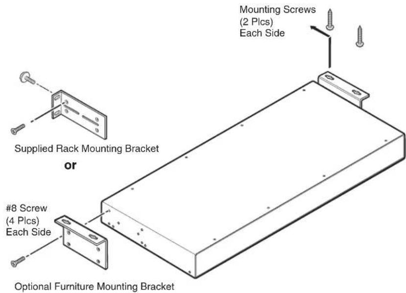
Figure 2-1 — Mounting a PIP
-
Insert the processor into the rack, align the holes in the mounting bracket with those of the rack.
-
Secure the processor to the rack using the supplied machine screws.
Table or wall mounting
The table/wall mounting brackets extend approximately 1/4" (6.4 mm) above the top surface of the processor enclosure. This design allows for an air space between the enclosure and the surface to which it is mounted. Table or wall mount the PIP as follows:
- Remove the feet from the underside of the PIP, if installed.
- Attach the table/wall mounting brackets to the processor with the eight provided #8 machine screws (figure 2-1).
- Hold the processor with the attached brackets against the underside of the table or other furniture, or against the wall. Mark the location of the screw holes of the bracket on the mounting surface.
- Drill 3/32" (2 mm) diameter pilot holes, 1/4" (6.4 mm) deep in the mounting surface at the marked screw locations.
- Insert #8 wood screws into the four pilot holes. Tighten each screw into the mounting surface until just less than 1/4" (6 mm) of the screw's head protrudes.
- Align the mounting screws with the slots in the brackets and place the processor against the surface, with the screws through the bracket slots.
- Slide the PIP slightly forward or back, then tighten all four screws to secure the processor in place.
Through-desk mounting
Mount the PIP through a desk or podium as follows:
- Remove the feet from the underside of the PIP, if installed.
- Attach the supplied mounting brackets to the processor with the machine screws provided (figure 2-1).
- Cut the proper sized hole in the mounting surface (figure 2-2).

natural_image
Technical diagram showing two views of a rectangular panel with internal channels and mounting base (no text or symbols)Figure 2-2 — Through desk mounting a PIP
- Hold the processor with the attached brackets against the underside of the table or other furniture. Mark the location of the screw holes of the bracket on the mounting surface.
- Drill 3/32" (2 mm) diameter pilot holes, 1/4" (6.3 mm) deep in the mounting surface at the marked screw locations.
- Insert four #8 wood screws through the bracket and into the four pilot holes. Tighten all four screws to secure the processor in place.
Rear Panel Connections

Figure 2-3 — PIP 422 rear panel

Figure 2-4 — PIP 444 rear panel
① Power connector — Plug the provided IEC power cord into this connector.
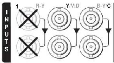
② Input (top) connectors — Connect up to two (PIP 422) or four (PIP 444) component video, S-video, or composite video input devices to these BNC connectors. Figure 2-5 shows how to connect the various video formats.
Component Video

flowchart
graph TD
    A["Input"] --> B["1"]
    B --> C["R-Y"]
    B --> D["Y/VID"]
    B --> E["B-Y/C"]
    F["Buffered Loop-through"] --> G["2"]
    G --> H["3"]
    G --> I["4"]
    G --> J["5"]
S-Video
flowchart
graph TD
    A["1"] --> B["R-Y"]
    C["2"] --> D["Y/VID"]
    B --> E["B-Y/C"]
    D --> E
    style A fill:#f9f,stroke:#333
    style C fill:#f9f,stroke:#333
    style B fill:#ccf,stroke:#333
    style D fill:#ccf,stroke:#333
    style E fill:#ccf,stroke:#333
Composite Video

flowchart
graph TD
    A["Input"] --> B["1"]
    B --> C["R-Y"]
    B --> D["Y/VID"]
    B --> E["B-Y/C"]
    F["Buffered Loop-through"] --> G["2"]
    G --> H["R-Y"]
    G --> I["Y/VID"]
    G --> J["B-Y/C"]
    C --> K["Cross"]
    D --> L["Cross"]
    E --> M["Cross"]
    F --> N["Cross"]
Figure 2-5 — Video input and buffered loop-through connections
NOTE
Connect only one video format to each input.
You must configure each input to identify the connected video format. See chapter 3, "Operation".
③ Input loop-through (bottom) connectors — If desired, connect local monitors to these female BNC connectors. The processor buffers the video input and loops it out on these connectors.
NOTE
The processor does not alter the video signal between the input and the buffered loop-through in any way. The processor's buffered loop-through output is in the same format as the input.
④ Output connectors — Connect a component video, S-video, and/or composite video display device to these BNC connectors. Figure 2-6 shows how to connect the various video formats.
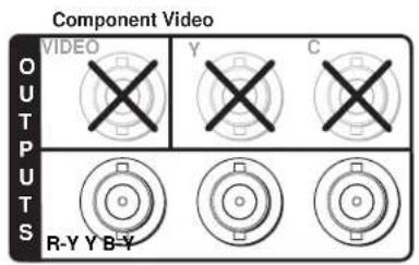
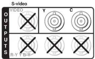
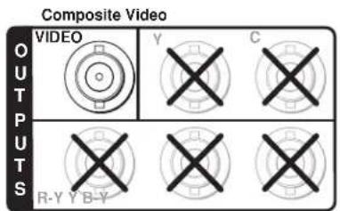
Figure 2-6 — Video output connections
NOTE
The component video, S-video, and composite video outputs are all active simultaneously, so multiple displays can be connected.
⑤ Genlock connectors (PIP 444 only) —
In(put) connector — Connect an external black burst signal to this BNC connector for genlocking the video signal in broadcast or other sync-critical applications.
Out(put) connector — Connect any downstream equipment that requires genlocking to this BNC connector to route the black burst signal throughout the system in broadcast or other sync-critical applications.
NOTE
If no device is connected to the output, terminate the Genlock output with the included 75-ohm terminator.
See "Setting Up Genlock and Vertical Interval Switching", on the next page, for detailed Genlock instructions.
⑥ RS-232/RS-422 connector — Connect a host computer or control system to this female 9-pin D connector to allow remote control of the PIP using Extron's Simple Instruction Set ^™ (SIS ^™ ) or control software for Windows ^® . (See Chapter 4, "Remote Control", for more information.)
Setting Up Genlock and Vertical Interval Switching
For vertical interval switching (to allow clean switching between signals from several devices during the vertical blanking period of each signal), a composite sync signal can be applied at the Genlock In connector, and also passed to another device via the Genlock Out connector.
If the genlock connectors are used only for vertical interval switching, no horizontal or subcarrier phase adjustments are required.
Genlock setup
Genlock differs from simple vertical interval switching in that an external device (a black burst generator) generates a reference sync signal for the system, and every device that uses that signal has its output signal's horizontal and subcarrier phases adjusted to exactly match that of the generator, allowing precise timing and full synchronization. Genlocked systems produce cleaner switches between inputs than do those without this type of synchronization.
An oscilloscope is required for genlock setup, and a vectorscope is recommended. Waveform monitors of types other than a vectorscope may give the appearance that timing is adjusted correctly when it is 180 degrees out of phase, which will result in incorrect colors or picture artifacts.
NOTE All equipment in the system must be powered up and turned on for at least 15 to 20 minutes before genlock setup adjustments can be made and before the equipment is used in a genlocked application.
To synchronize the PIP's video output with a genlock signal, follow these steps:
-
Power up and turn on all the devices that will use the genlock signal. The devices must be on for at least 15 to 20 minutes before proceeding with any adjustments.
-
Connect the active timing source signal to the Genlock In connector on the rear panel.
-
Connect the video input devices to the PIP, as described previously in this chapter.
-
Connect the oscilloscope ("scope") probe A to the Genlock Out connector. This will provide the scope's reference signal. In order to avoid altering the genlock signal, use the cabling configuration that will be used in the installation. Either connect the genlock signal cable from the scope to the next device in the system to be timed, or provide 75 ohm termination at the scope's genlock output.
-
Connect scope probe B to the PIP's composite video output connector.
-
Using the instructions for the scope you are using, set the scope to view the signals' horizontal phases. Adjust the horizontal phase until there is no (0°) difference between the composite video output's horizontal sync phase and the genlock signal's horizontal phase. See "Genlock configuration menu (PIP 444 only)" in chapter 3, "Operation", and "Oscilloscope displays" later in this chapter for details on adjusting the horizontal phase.
-
Set the scope to view the subcarrier signals. Adjust the subcarrier phase until there is a zero phase difference between the genlock signal and the NTSC/PAL output. See "Genlock configuration menu (PIP 444 only)" in chapter 3, "Operation", and "Oscilloscope displays" later in this chapter for details on adjusting the color subcarrier phase.
-
View the horizontal phases again. If the phase difference is not zero, repeat steps 6 and 7 until the settings do not change.
- Once the settings are stable, disconnect the oscilloscope, and reconnect the genlock cables.
- Check the display(s) for proper colors and for undesirable artifacts in the image(s). Make adjustments as necessary.
- If other PIPs are part of this genlock daisy chain, connect the oscilloscope to each device, and repeat this procedure.
Oscilloscope displays
What you see on the oscilloscope while adjusting the PIP to match the genlock signal depends on the type of signal used, the type of oscilloscope, and the procedure the scope requires. This section shows some examples of oscilloscope displays.
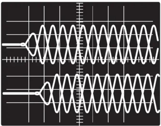
Figure 2-7 below shows the genlock input signal (top) and an out-of-alignment NTSC composite sync output signal (bottom) displayed on a waveform monitor to check for alignment. When the phases are aligned, the wave peaks on the bottom waveform should line up with those in the reference signal above it.
With this method there is no way to know if the signals are 180^ out of phase. A delayed sweep on a time-based scope would allow a more accurate display of the input and output signal phase relationships.
natural_image
Two overlapping sine waveforms on a grid background, no text or symbols presentFigure 2-7 — Superimposed waveforms
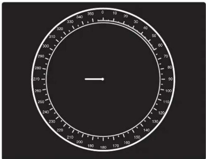
A vectorscope is more accurate than a waveform monitor. Figure 2-8 shows an example of a vectorscope display when the horizontal phase is adjusted to align it with the burst (genlock) vector. Adjust the horizontal phase by accessing the Genlock configuration menu and rotating either of the Adjust knobs until the difference between the two vectors is 0^ (see "Genlock configuration menu (PIP 444 only)" in chapter 3, "Operation" for more information). This example shows black burst only (with no color). The burst vector is pointing to the left from the center.
natural_image
Circular gauge or dial with numerical markings from 0 to 360, no readable text or symbols beyond the scale markings.Figure 2-8 — Vectorscope screen during horizontal phase adjustment
Figure 2-9 below shows an example of a view of a vectorscope during adjustment of the color subcarrier phase (SC/H). The subcarrier phase should be aligned to 0^ (indicated in the figure by the triangle).

Figure 2-9 — Vectorscope screen during color subcarrier phase adjustment
Chapter Three
Operation
Front Panel Features
Power-on Indications
Menu System
Picture Controls
Window Presets
Additional Functions
Optimizing the Image
Front Panel Features

flowchart
graph LR
    A["Extron"] --> B["21"]
    A --> C["5"]
    A --> D["64"]
    A --> E["3"]
    A --> F["7"]
    A --> G["8"]
    A --> H["9"]
    A --> I["PIP 422"]
    B --> J["Freeze"]
    C --> K["INPUTS"]
    D --> L["WIMP"]
    E --> M["PILOT EXTER"]
    F --> N["PILOT CONTROL"]
    G --> O["PILOT EXTER"]
    H --> P["PILOT EXTER"]
Figure 3-1 — PIP 422 front panel features

flowchart
graph LR
    A["Extron"] --> B["1 Freeze"]
    A --> C["2 INPUTS"]
    A --> D["3 VACOM"]
    A --> E["4 PICTORS ENTER"]
    A --> F["5 VACOM WITH OUTLET DIFFORM DETAIL POSITION SIZE ZOOM"]
    A --> G["6 PIP 444"]
    G --> H["7"]
    G --> I["8 921"]
Figure 3-2 — PIP 444 front panel features
① Freeze button and LEDs — Simultaneously press this button and an input button (②) to freeze that input's window in the displayed image. The Freeze LED for the input lights. Repeat to unfreeze the window.
② Input selector buttons — Press these buttons to enable or disable the inputs for display. The LEDs next to the buttons light to indicate the inputs are enabled.
These buttons are also used with the Freeze button (①) to toggle the freeze function for a specific input on or off.
③ Swap button (PIP 422 only) — Press the Swap button to exchange all window sizing, positioning, and priority settings. Press the SWAP button again to return the windows to their previous settings.
④ Window preset buttons — Press these buttons to save or recall a preset. See "Window Presets" later in this chapter for more information.
⑤ Window Select button and LEDs — Press this button to select a window to adjust using the picture control buttons (⑥) and Adjust knobs (⑨) or using the Input Configuration submenu. The lit LED indicates which window is selected.
⑥ Picture Control buttons — The Picture Control buttons select individual image adjustments that are adjusted using the Adjust ◀ and Adjust ◆knobs (⑨).
• Color/Tint control button — The Color/Tint button selects the display color and tint adjustments. See "Picture Controls" in this chapter.
NOTE Tint control is not available for PAL inputs.
- Brightness/Contrast control button — The Brightness/Contrast button selects the display brightness and contrast adjustments. See “Picture Controls” in this chapter.
• Detail button — The Detail button selects the display image detail (sharpness) adjustment and the anti-aliasing adjustment.
The sharpness adjustment compensates for long cable runs. There are separate horizontal and vertical filters for component video. There is a single filter for S-video and composite video.
The anti-aliasing adjustment reduces or eliminates the aliasing effect.
- Position button — The Position button selects the window display centering adjustment and toggles between the window and image adjustments. See “Picture Controls” in this chapter.
- Size control button — The Size button selects the window display size adjustment and toggles between the window and image adjustments. See "Picture Controls" in this chapter.
- Zoom control button — The Size button selects the window zoom in/out adjustment and toggles between the window and image adjustments. See "Picture Controls" in this chapter.
⑦ LCD display — This 12 x 2 LCD displays configuration menus and status information. See “Menu System” in this chapter for more information on the menus.
⑧ Menu button — The Menu button enters and moves through the main menu system in the PIP. See "Menu System" in this chapter for details.
Next button — The Next button steps through the submenus in the PIP menu system. See "Menu System" in this chapter for details.
⑨ Adjust ◀ (horizontal) and Adjust ◆ (vertical) knobs — The Adjust ◄ and Adjust ◆ knobs change settings when used in conjunction with the picture adjustment buttons or the menu system. Rotate these knobs to change picture settings when one of the picture adjustment buttons is selected. In the menu system, rotate these knobs to scroll through the selection options and make adjustments. See “Menu System”, “Picture Controls”, and “Window Presets” in this chapter for more information.
Power-on Indications
Power is automatically applied when the power cord is connected to an AC source. When AC power is applied, the switcher performs a self-test that blinks all of the front panel LEDs and then lights only the LEDs for the inputs previously selected for the display. The self-test also displays the model name, part number, and the firmware version in the LCD display. After approximately 2 seconds, the LCD reverts to its default display cycle, alternating among several displays; one for each input that shows that input's configuration, and the last showing the selected output standard (figure 3-3). An error-free power up self-test sequence leaves all of the LEDs, with the exception of the selected inputs' LED(s), off and the LCD displaying the default display cycle.
The selected inputs and their size and position on the display, the picture adjustments, and other current settings are saved in nonvolatile memory. When power is applied, the latest configuration is retrieved.
NOTE
On figure 3-3 and all other flowcharts in this chapter, solid lines indicate screen changes initiated by the operator. Dashed lines indicate screen changes that are the result of a timeout function.

flowchart
graph TD
    A["Power on"] --> B["Extron, Inc. PIP 444 (422)"]
    B --> C["60-606 (607)-01 FW ver. n.nn"]
    C --> D["Input #1 NTSC"]
    D --> E["Input #2 Mono 60"]
    E --> F["Input #3* PAL"]
    F --> G["Output Std NTSC"]
    G --> H["Input #4* Frozen"]
    H --> I["1 sec."]
    I --> J["1 sec."]
    J --> K["1 sec."]
    K --> L["1 sec."]
    L --> M["1 sec."]
    M --> N["1 sec."]
    N --> O["1 sec."]
    O --> P["1 sec."]
    P --> Q["1 sec."]
    Q --> R["1 sec."]
    R --> S["1 sec."]
    S --> T["1 sec."]
    T --> U["1 sec."]
    U --> V["1 sec."]
    V --> W["1 sec."]
    W --> X["1 sec."]
    X --> Y["1 sec."]
    Y --> Z["1 sec."]
    Z --> AA["1 sec."]
    AA --> AB["1 sec."]
    AB --> AC["1 sec."]
    AC --> AD["1 sec."]
    AD --> AE["1 sec."]
    AE --> AF["1 sec."]
    AF --> AG["1 sec."]
    AG --> AH["1 sec."]
    AH --> AI["1 sec."]
    AI --> AJ["1 sec."]
    AJ --> AK["1 sec."]
    AK --> AL["1 sec."]
    AL --> AM["1 sec."]
    AM --> AN["1 sec."]
    AN --> AO["1 sec."]
    AO --> AP["1 sec."]
    AP --> AQ["1 sec."]
    AQ --> AR["1 sec."]
    AR --> AS["1 sec."]
    AS --> AT["1 sec."]
    AT --> AU["1 sec."]
    AU --> AV["1 sec."]
    AV --> AW["1 sec."]
    AW --> AX["1 sec."]
    AX --> AY["1 sec."]
    AY --> AZ["1 sec."]
    AZ --> BA["1 sec."]
    BA --> BB["1 sec."]
    BB --> BC["1 sec."]
    BC --> BD["1 sec."]
    BD --> BE["1 sec."]
    BE --> BF["1 sec."]
    BF --> BG["1 sec."]
    BG --> BH["1 sec."]
    BH --> BI["1 sec."]
    BI --> BJ["1 sec."]
    BJ --> BK["1 sec."]
    BK --> BL["1 sec."]
    BL --> BM["1 sec."]
    BM --> BN["1 sec."]
    BN --> BO["1 sec."]
    BO --> BP["1 sec."]
    BP --> BQ["1 sec."]
    BQ --> BR["1 sec."]
    BR --> BS["1 sec."]
    BS --> BT["1 sec."]
    BT --> BU["1 sec."]
    BU --> BV["1 sec."]
    BV --> BW["1 sec."]
    BW --> BX["1 sec."]
    BX --> BY["1 sec."]
    BY --> BZ["1 sec."]
    BZ --> CA["1 sec."]
    CA --> CB["1 sec."]
    CB --> CC["1 sec."]
    CC --> CD["1 sec."]
    CD --> CE["1 sec."]
    CE --> CF["1 sec."]
    CF --> CG["1 sec."]
    CG --> CH["1 sec."]
    CH --> CI["1 sec."]
    CI --> CJ["1 sec."]
    CJ --> CK["1 sec."]
    CK --> CL["1 sec."]
    CL --> CM["1 sec."]
    CM --> CN["1 sec."]
    CN --> CO["1 sec."]
    CO --> CP["1 sec."]
    CP --> CQ["1 sec."]
    CQ --> CR["1 sec."]
    CR --> CS["1 sec."]
    CS --> CT["1 sec."]
    CT --> CU["1 sec."]
    CU --> CV["1 sec."]
    CV --> CW["1 sec."]
    CW --> CX["1 sec."]
    CX --> CY["1 sec."]
    CY --> CZ["1 sec."]
    CZ --> DA["1 sec."]
    DA --> DB["1 sec."]
    DB --> DC["1 sec."]
    DC --> DV["1 sec."]
    DV --> DW["1 sec."]
    DW --> BX
Figure 3-3 — PIP 444 default display cycle
Menu System
Menu system overview
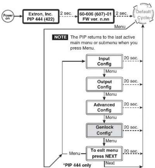
Figure 3-4 shows a flowchart of the main menu system.
flowchart
graph TD
    A["Power on"] --> B["Extron, Inc. PIP 444 (422)"]
    B -->|2 sec.| C["60-606 (607)-01 FW ver. n.nn"]
    C -->|2 sec.| D["Default Cycle"]
    D --> E["Menu"]
    E --> F["Input Config"]
    F --> G["Output Config"]
    G --> H["Advanced Config"]
    H --> I["Genlock Config*"]
    I --> J["To exit menu press NEXT"]
    J --> K["Next"]
    K --> L["*PIP 444 only"]
    L --> M["Menu"]
    M --> N["Note: The PIP returns to the last active main menu or submenu when you press Menu."]
    N --> O["20 sec."]
    O --> P["20 sec."]
    P --> Q["20 sec."]
    Q --> R["20 sec."]
    R --> S["20 sec."]
    S --> T["20 sec."]
    T --> U["20 sec."]
    U --> V["20 sec."]
    V --> W["20 sec."]
    W --> X["20 sec."]
    X --> Y["20 sec."]
    Y --> Z["20 sec."]
Figure 3-4 — PIP 444 menu system flowchart
Menu button — Press the Menu button to activate the menu system and to scroll through the four main menus.
Next button — Press the Next button to move between the submenus of a selected main menu, to activate one for viewing or configuration, and to save a selection. Pressing the Next button during input configuration causes the current input's number and format type to be displayed on the LCD.
Adjust ◀ and Adjust ◆ knobs — When in a submenu, rotate the Adjust ◀ knob and Adjust ◆ knob to scroll through the submenu options and select a setting. Refer to the flowcharts in this chapter and to specific sections for explanations on knob adjustments.
NOTE If you press the Menu button while a main menu or a submenu is active, the next main menu becomes active. For example, the display changes from the Input Configuration main menu or the Input Format submenu to the Output Configuration main menu.
NOTE To return to the default screens, let the processor remain idle for 10 seconds until the selected screen times out, or press the Menu button until the Exit menu appears, then press the Next button.
NOTE From any menu or submenu, after 10 seconds of inactivity, the PIP saves all adjustment settings and times-out to the default LCD display cycle.
Input Configuration menu
Figure 3-5 is a flowchart that shows an overview of the Input Configuration menu and the available settings.

flowchart
graph TD
    A["Default Cycle"] --> B["Input Config"]
    B --> C["Output Config"]
    C --> D["Advanced Config"]
    D --> E["Genlock Config*"]
    E --> F["To exit menu press NEXT"]
    F --> G["Menu"]
    G --> H["Menu"]
    H --> I["Note: The PIP returns to the last active main menu or submenu when you press Menu."]
    I --> J["Menu"]
    J --> K["Input #1 Fmt Video"]
    K --> L["Next"]
    L --> M["Input video type"]
    M --> N["Video* (Composites)"]
    M --> O["S-video"]
    M --> P["YUV (Component) (* Default)"]
    K --> Q["Inputs"]
    Q --> R["(Or push the Window Select button.)"]
    R --> S["+1 2 3 4 *PIP 444 only"]
    S --> T["Next"]
    T --> U["20 sec."]
    U --> V["20 sec."]
Figure 3-5 — Input Configuration menu flowchart
The Input Configuration menu consists of one submenu that allows you to select the type of video signal that each of the four inputs will pass. You can configure each input to accept Video (composite video), S-video, or YUV (component video). Rotate the Adjust ◀ knob to select the input and the Adjust ◀ knob to select the video signal type.
NOTE Only one video format can be assigned to each input.
Output Configuration menu
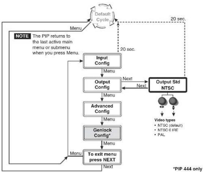
Figure 3-6 is a flowchart that shows an overview of the Output Configuration menu and the available settings.
flowchart
graph TD
    A["Default Cycle"] --> B["Input Config"]
    B --> C["Output Config"]
    C --> D["Advanced Config"]
    D --> E["Genlock Config*"]
    E --> F["To exit menu press NEXT"]
    F --> G["Next"]
    G --> H["Output Std NTSC"]
    H --> I["Video types: NTSC (default), NTSC © IRE, PAL"]
    I --> J["20 sec."]
    J --> K["Menu"]
    K --> L["Note: The PIP returns to the last active main menu or submenu when you press Menu."]
    L --> M["Menu"]
    M --> N["Next"]
    N --> O["Output Std NTSC"]
    O --> P["Video types: NTSC (default), NTSC © IRE, PAL"]
    P --> Q["20 sec."]
    Q --> R["Output Std NTSC"]
    R --> S["Video types: NTSC (default), NTSC © IRE, PAL"]
    S --> T["20 sec."]
    T --> U["Next"]
    U --> V["Output Std NTSC"]
    V --> W["Video types: NTSC (default), NTSC © IRE, PAL"]
    W --> X["20 sec."]
    X --> Y["Output Std NTSC"]
    Y --> Z["Video types: NTSC (default), NTSC © IRE, PAL"]
    Z --> AA["20 sec."]
    AA --> AB["Output Std NTSC"]
    AB --> AC["Video types: NTSC (default), NTSC © IRE, PAL"]
    AC --> AD["20 sec."]
    AD --> AE["Output Std NTSC"]
    AE --> AF["Video types: NTSC (default), NTSC © IRE, PAL"]
    AF --> AG["20 sec."]
    AG --> AH["Output Std NTSC"]
    AH --> AI["Video types: NTSC (default), NTSC © IRE, PAL"]
    AI --> AJ["20 sec."]
    AJ --> AK["Output Std NTSC"]
    AK --> AL["Video types: NTSC (default), NTSC © IRE, PAL"]
    AL --> AM["20 sec."]
    AM --> AN["Output Std NTSC"]
    AN --> AO["Video types: NTSC (default), NTSC © IRE, PAL"]
    AO --> AP["20 sec."]
    AP --> AQ["Output Std NTSC"]
    AQ --> AR["Video types: NTSC (default), NTSC © IRE, PAL"]
    AR --> AS["20 sec."]
    AS --> AT["Output Std NTSC"]
    AT --> AU["Video types: NTSC (default), NTSC © IRE, PAL"]
    AU --> AV["20 sec."]
    AV --> AW["Output Std NTSC"]
    AW --> AX["Video types: NTSC (default), NTSC © IRE, PAL"]
    AX --> AY["20 sec."]
    AY --> AZ["Output Std NTSC"]
    AZ --> BA["Video types: NTSC (default), NTSC © IRE, PAL"]
    BA --> BB["20 sec."]
    BB --> BC["Output Std NTSC"]
    BC --> BD["Video types: NTSC (default), NTSC © IRE, PAL"]
    BD --> BE["20 sec."]
    BE --> BF["Output Std NTSC"]
    BF --> BG["Video types: NTSC (default), NTSC © IRE, PAL"]
    BG --> BH["20 sec."]
    BH --> BI["Output Std NTSC"]
    BI --> BJ["Video types: NTSC (default), NTSC © IRE, PAL"]
    BJ --> BK["20 sec."]
    BK --> BL["Output Std NTSC"]
Figure 3-6 — Output Configuration menu flowchart
The Output Configuration menu consists of one submenu that allows you to select a video standard for the output signal. Rotate either Adjust knob to choose between NTSC, NTSC 0 IRE, and PAL video.
Advanced Configuration menu
Figure 3-7 is a flowchart that shows an overview of the Advanced Configuration menu, the submenus, and the available settings.
The Advanced Configuration menu has four submenus that allow you to view and select the border color, background color, window transition effect, priority, and anti-aliasing mode for the windows and a fifth submenu that displays the device's temperature. Rotate either of the Adjust knobs to select settings from each of the submenus.

flowchart
graph TD
    A["Menu"] --> B["Input Config"]
    B --> C["Output Config"]
    C --> D["Advanced Config"]
    D --> E["Genlock Config*"]
    E --> F["To exit menu press NEXT"]
    F --> G["Next"]
    G --> H["Border Off"]
    H --> I["Next"]
    I --> J["Background Black"]
    J --> K["Next"]
    K --> L["Effect Type Wipe"]
    L --> M["Win Priority F <1>2 3 4 B"]
    M --> N["Next"]
    N --> O["Temperature* +91F +33C"]
    O --> P["NextNext"]
    P --> Q["*Newer models only"]
    Q --> R["Select Input 1 • 2 3 • 4"]
    R --> S["Input window priority Set the priority order. Order the selected input number from left (the selected input appears in front) to right (the selected input appears in back)."]
    S --> T["Window transition effect Cut* Wipe Dissolve†Default"]
    T --> L
    style A fill:#f9f,stroke:#333
    style P fill:#ccf,stroke:#333
Figure 3-7— Advanced Configuration menu flowchart
Border Color submenu
Use this submenu to select a border color for all the windows. Available colors are white, yellow, cyan, green, magenta, red, blue, or black. You can also select off, which is the default setting.
Background Color submenu
This submenu allows you to select a background color for all the windows. Available colors are white, yellow, cyan, green, magenta, red, blue, or black. Black is the default setting.
Window Effect submenu
Use this submenu to select a transition effect for the PIP to use when enabling, disabling, or swapping windows. You can choose from the following three options:
Cut — The window turns seamlessly on and off. No effect is applied to the transition. This is the default setting.
Wipe — The window appears to unroll over the old screen, from left to right.
Dissolve — The window appears to dissolve on or off.
NOTE The wipe and dissolve effects are set to a fixed 0.5 second transition interval, which cannot be changed.
Window Priority submenu
The Window Priority submenu allows you to set how the windows will overlap one another. The submenu lists the inputs in order of their priority, from left to right. The input that appears in the leftmost position in the submenu will appear in front of all the other windows. Rotate the Adjust ◆ knob to select an input to adjust. Rotate the Adjust ◀ knob to set the priority of the input.

Temperature submenu
This display only submenu shows the temperature of the PIP in degrees Fahrenheit and Celsius.
NOTE The Temperature submenu is available only on newer models.
Genlock Configuration menu (PIP 444 only)
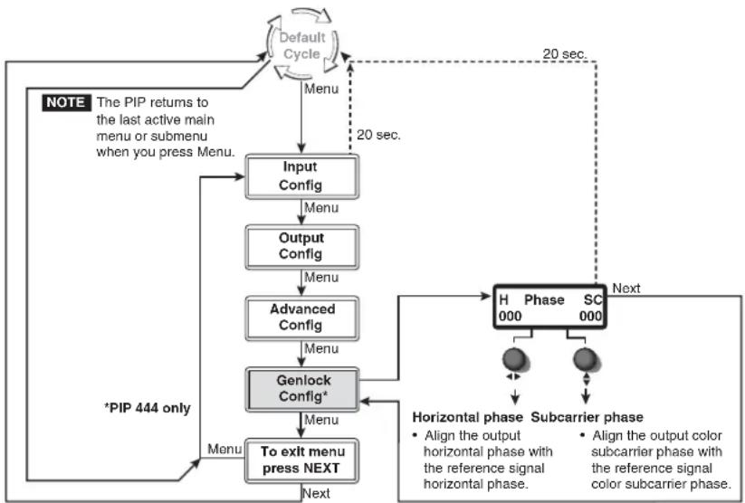
Figure 3-8 is a flowchart that shows an overview of the Genlock Configuration menu, the submenus, and the available settings.
flowchart
graph TD
    A["Default Cycle"] --> B["Menu"]
    B --> C["Input Config"]
    C --> D["Output Config"]
    D --> E["Advanced Config"]
    E --> F["Genlock Config*"]
    F --> G["To exit menu press NEXT"]
    G --> H["Next"]
    H --> I["Horizontal phase H Phase SC 000"]
    I --> J["Subcarrier phase"]
    J --> K["• Align the output color subcarrier phase with the reference signal color subcarrier phase."]
    K --> L["Next"]
    M["*PIP 444 only"] --> N["Menu"]
    N --> O["Input Config"]
    O --> P["Output Config"]
    P --> Q["Advanced Config"]
    Q --> R["Genlock Config*"]
    R --> S["To exit menu press NEXT"]
    S --> T["Next"]
    T --> U["20 sec."]
    U --> V["20 sec."]
    V --> W["NOTE: The PIP returns to the last active main menu or submenu when you press Menu."]
Figure 3-8 — Genlock Configuration menu flowchart
The Genlock Configuration menu allows you to align the horizontal phase and color subcarrier phase of the output signal with those of the genlock reference (black burst) signal. Rotate the Adjust ◀▶ knob to align the horizontal phase and the Adjust ◆ knob to align the subcarrier phase through a range from 0 to 255.
Exit menu
From the Exit menu (figure 3-9), press the Next button to return to the default display cycle, or press the Menu button to return to the Input Configuration menu.

flowchart
graph TD
    A["Input Config"] -->|Menu| B["Output Config"]
    B -->|Menu| C["Advanced Config"]
    C -->|Menu| D["Genlock Config*"]
    D -->|Menu| E["To exit menu press NEXT"]
    E -->|Next| F["Default Cycle"]
    F -->|Next| G["*PIP 444 only"]
    G -->|Menu| A
    H["Menu"] --> A
    I["20 sec."] -.-> J["Default Cycle"]
Figure 3-9 — Exit menu flowchart
Picture Controls
The picture adjustments allow you to fine tune the image quality of the selected window. When you press one of the Picture Control buttons (Color/Tint, Brightness/Contrast, Detail (filter), Position, Size, or Zoom), the corresponding picture adjustment menu for the selected window appears in the LCD (figure 3-10). For Position, Size, and Zoom, press the button again, and the corresponding image adjustment menu for the image within the window appears. In either screen, adjustments can then be made by rotating the Adjust ◄▶ knob or Adjust ◆ knob. Picture control settings are stored in nonvolatile memory; when the processor is powered down and then powered up, the settings are restored.
NOTE See Auto-center the image on page 3-12 to automatically center the image within the active window.
When a window or image adjustment is selected, the window that is selected for adjustment by using the Window Select button is indicated on the displayed image by a blinking border. Borders on the unselected windows are temporarily turned off.

flowchart
graph TD
    A["Window Select"] --> B["COL/TINT"]
    A --> C["BRT/CONT"]
    B --> D["Color 063"]
    B --> E["Tint 031"]
    C --> F["Bright 063"]
    C --> G["Cont 031"]
    D --> H["Detail 07"]
    E --> H
    F --> I["H WinPos V 045 007"]
    G --> I
    H --> J["DETAIL POSITION SIZE"]
    I --> K["H Win Size V 024 063"]
    J --> L["ZOOM"]
    K --> M["H Win Zoom V 024 053"]
    L --> N["ZOOM"]
    M --> O["POSITION DETAIL SIZE"]
    N --> O
    O --> P["Antialiasing Auto"]
    P --> Q["H ImgPos V +045 -007"]
    Q --> R["POSITION DETAIL SIZE"]
    R --> S["H Img Size V -024 +063"]
    S --> T["ZOOM"]
    T --> U["H Img Zoom V +024 -053"]
    U --> V["Display Cycle"]
    style A fill:#f9f,stroke:#333
    style V fill:#ccf,stroke:#333
NOTE The Window Select button selects the window to which the adjustment is applied.
The Adjust ◆knob and the Adjust ◆knob adjust the image settings on the left and right sides of the LCD.
Push the Position, Size, and Zoom buttons to toggle between the window adjustment and the overall image adjustment.
Push the Detail button to toggle between the detail adjustment and the anti-aliasing adjustment.
Image size, image position, and image zoom adjustments are relative to the currently selected window's size and position settings.
Figure 3-10 — Picture controls flowchart
Adjust an image as follows (figure 3-10):
- Press the Window Select button repeatedly until the Window Select LED for the desired window lights.
- Press the button for the picture control you want to adjust. The LCD displays the appropriate adjustment menu for that window and picture control.
-
Press the Size, Position, or Zoom button as necessary to toggle between the adjustment menus that allow you to adjust the window itself and the adjustment menus that allow you to adjust the image within the window.
-
Rotate the Adjust ◀ knob or Adjust ◆ knob to vary the settings within the following adjustment ranges:
NOTE The Adjust knobs have no mechanical limits to their rotation.
• Color/Tint: The range for both adjustments is 0 to 127.
- Brightness/Contrast: The range for brightness is 50 to 127. The range for contrast is 38 to 107.
- Filter: Push the Detail button to toggle between the detail filter adjustment and the anti-aliasing adjustment.
Detail: Either knob sets the detail filter within a range from 0 (the softest detail) to 15 (the crispest detail). The default is 8 (no filtering).
NOTE The Detail filter is only available for inputs that are configured as S-video or composite video.
Anti-aliasing: Either knob sets the anti-aliasing filter within a range from off (default), mode 0 to 3, or auto. In auto, the PIP selects the auto-aliasing setting by the size of the window.
- Position: Push the Position button to toggle between the position adjustment for the selected window (indicated by the lit Window Select LED) and for the image within the selected window.
Window Position: Observe the display and turn the Adjust ◀ knob to move the selected window side to side. Turn the Adjust ◀ knob to move the selected window up and down.
Image Position: Observe the display and turn the Adjust ◀ knob to move the image side to side in the selected window. Turn the Adjust ◀ knob to move the image up and down in the selected window.
- Size: Push the Size button to toggle between the size adjustment for the selected window and for the image within the window.
Window Size: Observe the display and turn the Adjust ◄ knob to stretch or shrink the selected window from side to side. Turn the Adjust ◄ knob to stretch or shrink the selected window up and down.
Image Size: Observe the display and turn the Adjust ◀ knob to stretch or shrink left and right the image within the selected window. Turn the Adjust ◀ knob to stretch or shrink in the selected window up or down.
- Zoom: Push the Zoom button to toggle between the zoom adjustment for the selected window and for the image within the window.
Window Zoom: Observe the display and turn either Adjust knob to zoom in on or zoom out from the selected window.
Image Zoom: Observe the display and turn either Adjust knob to zoom in on or zoom out from the image in the selected window.
- Repeat steps 2 and 4 for each image adjustment to be made for the selected window.
Repeat steps 1, 2, 4, and 5 for each window.
- To exit to the default cycle, do nothing for approximately 20 seconds; the PIP times out and return to the default display cycle.
Auto-center the image
To automatically center the image within the currently selected window, press and hold the Position and Size buttons for approximately half a second.
NOTE
The auto-center function does not work if the image size is set extremely small, relative to the window size.
Window Presets
The PIP 422 has 10 preset slots that save settings for the number, size, position, priority, text and colors of the windows' borders and background. The PIP 444 has 20 preset slots. Both processors come with default window presets saved in these slots (figure 3-11 and figure 3-12). You can replace the default presets with your own settings by following the save procedure that follows the figures.

Figure 3-11 — PIP 422 default window presets

Figure 3-12 — PIP 444 default window presets
Recall a preset
- Press the Preset button. The Recall menu appears on the LCD.
- Turn either Adjust knob to select the preset you want to recall.
- Press the Enter button.
Save the current window settings as a preset
- Press and hold the Preset button for 2 seconds. The Save menu appears on the LCD. Release the Preset button.
- Turn either Adjust knob to select the preset you want to replace.
- Press the Enter button.
Additional Functions
Freeze mode
The PIP 444's Freeze mode lets you freeze an input to the current image. When frozen, the image is saved in the PIP's memory and will not be lost if you disconnect the input.
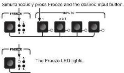
To freeze an input's window in the currently-displayed image, simultaneously press the Freeze button and the desired input's selection button (figure 3-13). The LED for the input lights. Repeat to unfreeze the window.

Recalling a preset or adjusting the size of a frozen image unfreezes the image.
flowchart
graph TD
    A["Simultaneously press Freeze and the desired input button."] --> B["FREEZE"]
    B --> C["1 2 3 4"]
    C --> D["INPUTS"]
    D --> E["1 234"]
    E --> F["OUTPUTS"]
    F --> G["FREEZE"]
    G --> H["1 2 3 4"]
    H --> I["The Freeze LED lights."]
Figure 3-13— Freeze mode flowchart
Front panel security lockout (Executive mode)
To prevent accidental changes to the PIP 444's settings, you can lock the front panel picture control and Menu and Next buttons. The input, freeze, and preset recall functions are still active when the front panel is locked.
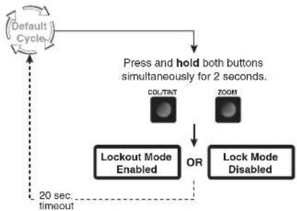
To toggle the front panel lock on and off, press and hold the Color/Tint and Zoom buttons simultaneously for 2 seconds (figure 3-14). Alternatively, you can use the appropriate SIS command (see chapter 4, "Remote Control" for more information). The LCD panel displays the message Lockout Mode Enabled for two seconds and then returns to the default display cycle. This message appears again if you press any of the picture control or the Menu or Next buttons while they are locked.
flowchart
graph TD
    A["Default Cycle"] --> B["Press and hold both buttons simultaneously for 2 seconds."]
    B --> C["Lockout Mode Enabled"]
    B --> D["Lock Mode Disabled"]
    C --> E["OR"]
    D --> E
    E --> F["20 sec timeout"]
    F --> A
Figure 3-14 — Front panel security lockout flowchart
Unit reset
To reset the PIP to its factory default settings, press and hold the Menu and Next buttons while you power up the processor (figure 3-15). The LCD panel displays the message System Reset for two seconds and then begins the default display cycle.

flowchart
graph TD
    A["Press and hold both buttons simultaneously while applying power."] --> B["MENU NEXT"]
    B --> C["SYSTEM RESET"]
    C --> D["2 sec."]
    D --> E["Extron, inc. PIP 444 (422)"]
    E --> F["2 sec."]
    F --> G["60-606 (607)-01 FW ver. n.nn"]
    G --> H["10 sec."]
    H --> I["Default Cycle"]
    I --> J["Power"]
Figure 3-15 — System reset flowchart
Selecting the baud rate and RS-232/RS-422 protocol
The processor can operate at 9600, 19200, 38400, and 115200 baud rates and support either RS-232 or RS-422 serial communication protocol. The settings of these variables can be viewed and changed from the front panel.
View and configure the switcher's serial communications settings as follows:
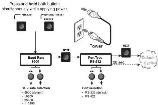
- To enter Serial Port Configuration mode, simultaneously press and hold the Freeze button and Preset button while you apply power to the processor (figure 3-16). The processor's LCD displays the baud rate upon completion of the power up process.
flowchart
graph TD
    A["Press and hold both buttons simultaneously while applying power."] --> B["Baud Rate 9600"]
    B --> C["PORT Type RS-232"]
    C --> D["Default Cycle"]
    E["Pressure"] --> F["FREEZE"]
    G["Window Preset"] --> H["PRESSET"]
    I["Power"] --> J["Next"]
    K["Baud rate selection"] --> L["9600 (default)"]
    K --> M["19200"]
    K --> N["38400"]
    K --> O["115200"]
    P["Port selection"] --> Q["RS-232 (default)"]
    P --> R["RS-422"]
    S["Next"] --> T["20 sec."]
    T --> C
Figure 3-16 — RS-232/RS-422 and baud rate selection
- Release the Freeze and Preset buttons.
- To change the baud rate, rotate either Adjust knob.
- Press and release the Next button. The LCD displays the serial port protocol.
- To change the serial port protocol, rotate either Adjust knob.
- Press and release the Menu button or wait approximately 20 seconds. The processor reverts to the default display cycle.
Optimizing the Image
Before storing any user presets, adjust the input window images for optimum color, tint, brightness, contrast, detail filter, positioning, sizing, and zoom. Upon initial power up of the PIP, factory pattern #01 in figure 3-11 (PIP 422) or figure 3-12 (PIP 444) is the default windows preset. Using this preset, all four input windows may be optimized, as shown in the following steps. See the flowchart in the "Menu system overview" section for further details.
- As necessary, press the Window Select button to select the desired window to adjust. The appropriate Window Select LED lights.
- As necessary perform the following picture control adjustments:
a. Color — Press the Color/Tint button and then rotate the Adjust ◀ knob to increase or decrease the window color from 0 to 127 (the default is 64).
b. Tint — Press the Color/Tint button and then rotate the Adjust ◆ knob to increase or decrease the window tint from 0 to 127 (the default is 64).
c. Brightness — Press the Brightness/Contrast button and then rotate the Adjust ◀ knob to increase or decrease the window brightness from 50 to 127 (the default is 64).
d. Contrast — Press the Brightness/Contrast button and then rotate the Adjust ◆ knob to increase or decrease the window contrast from 38 to 107 (the default is 68).
e. Detail filter — Press the Detail button and then rotate either Adjust knob to change the filter setting from 0 (the softest detail) to 15 (the crispest detail). The default is 8 (no filtering).
f. Anti-aliasing filter — Press the Detail button twice and then rotate either Adjust knob to change the anti-aliasing setting from off, 0 to 3, or auto (the default is off).
g. Horizontal window positioning — Press the Position button and then rotate the Adjust ◄ Knob to move the left edge of the selected window to the desired location.
NOTE Keep in mind that sizing the window horizontally moves the right edge of the window only.
h. Horizontal image positioning within the window — Press the Position button a second time and then rotate the Adjust ◀▶ knob to move the left edge of the image within the selected window to the desired location.
i. Horizontal window sizing — Press the Size button and then rotate the Adjust ◀ knob to set the right edge of the window.
j. Horizontal image sizing within the window — Press the Size button a second time and then rotate the Adjust ◀▶ knob to set the right edge of the image within the selected window.
k. Vertical window positioning — Press the Position button and then rotate the Adjust ◆ knob to move the top edge of the selected window to the desired location.
NOTE Keep in mind that sizing the window vertically moves the bottom edge of the window only.
- Vertical image positioning within the window — Press the Position button a second time and then rotate the Adjust ◆ knob to move the top edge of the image in the selected window to the desired location.
m. Vertical window sizing — Press the Size button and then rotate the Adjust ◆ knob to set the bottom edge of the window.
n. Vertical image sizing within the window — Press the Size button a second time and then rotate the Adjust ◆ knob to set the bottom edge of the image within the selected window.
o. Automatic image positioning within the window — Press and hold the Size and Position buttons for approximately half a second to automatically center the image within the currently selected window. Release the buttons.
NOTE The auto-center function does not work if the image size is set extremely small, relative to the window size.
p. Zoom — Press the Zoom button and then rotate the Adjust ◀ knob to set the bottom right corner of the window. The aspect ratio is maintained.
-
If any of the windows requires further positioning/sizing, repeat steps 1 and 2.
-
After optimizing the window image(s), save the configuration, as follows: Press the Preset button for 2 seconds. When the LCD displays "Save to Preset #n", rotate either Adjust knob to select a preset location in which to save the settings. Press the Enter button. See the "Window Presets" section for a detailed explanation.
Chapter Four
Remote Control
Simple Instruction Set Control
Control Software for Windows®
The PIP's RS-232/422 port is used to connect to a host or external controlling device, such as a computer or control system, which can generate the proper command codes and recognize the processor's responses.
NOTE The cable used to connect the RS-232/RS-422 port to a computer or control system may need to be modified by removing pins or cutting wires. If unneeded pins are connected, the processor may hang up. See chapter 2, "Installation", for more information on wiring the connectors.
The RS-232/RS-422 connector is a 9-pin D female (figure 4-1). The default protocol is RS-232, 9600 baud, 8-bit, 1 stop bit, no parity, and no flow control.
NOTE See "Selecting the baud rate and RS-232/RS-422 protocol" in chapter 3, "Operation", to change the protocol.
| RS-232FunctionPin RS-422 Function | ||||
| 1 | — | Not used | — | Not used |
| 2 | TX | Transmit data | TX− | Transmit data (−) |
| 3 | RX | Receive data | RX− | Receive data (−) |
| 4 | — | Not used | — | Not used |
| 5 | Gnd | Signal ground | Gnd | Signal ground |
| 6 | — | Not used | — | Not used |
| 7 | — | Not used | RX+ | Receive data (+) |
| 8 | — | Not used | TX+ | Transmit data (+) |
| 9 | — | Not used | — | Not used |
Figure 4-1 — RS-232/RS-422 pinout
Simple Instruction Set Control
Host-to-PIP communications
The PIP 444 and PIP 422 accept SISTM (Simple Instruction SetTM) commands through the RS-232/RS-422 port. SIS commands consist of one or more characters per command field. They do not require any special characters to begin or end the command character sequence. Each response to an SIS command ends with a carriage return and a line feed (CR/LF = ) which signals the end of the response character string. A string is one or more characters.
PIP-initiated messages
(C) Copyright 2005, Extron Electronics, PIP 422 (444), V. x.xx
Error responses
When the PIP receives a valid SIS command, it executes the command and sends a response to the host device. If the processor is unable to execute the command because the command is invalid or contains invalid parameters, it returns an error response to the host. The error response codes are:
E01 — Invalid input channel number (too large)
E09 — Invalid function number (too large)
E10 — Invalid command
E11 — Invalid preset
E13 — Invalid value (out of range)
E23 — Checksum error
Using the command/response tables
The command/response table is shown beginning on page 4-5. Symbols, defined on page 4-4 are used throughout the table to represent variables in the command/response fields. An ASCII-to-hexadecimal (HEX) conversion table is provided below. Symbol definitions are provided below. Command and response examples are shown throughout the command/response table.
| ASCII to HEX Conversion Table | Esc | 1B | CR | ∅D | LF | ∅A | |||||||||
| 200 | 20 | ! | 21 | * | 22 | # | 23 | $ 24 | % | 25 | & | 26 | ' | 27 | |
| ( | 28 | ) | 29 | * | 2A | + | 2B | , | 2C | - | 2D | . | 2E | / | 2F |
| ∅ | 30 | 1 | 31 | 2 | 32 | 3 | 33 | 4 | 34 | 5 | 35 | 6 | 36 | 7 | 37 |
| 8 | 38 | 9 | 39 | : | 3A | ; | 3B | < | 3C | = | 3D | > | 3E | ? | 3F |
| @ | 40 | A | 41 | B | 42 | C | 43 | D | 44 | E | 45 | F | 46 | G | 47 |
| H | 48 | | | 49 | J | 4A | K | 4B | L | 4C | M | 4D | N | 4E | O | 4F |
| P | 50 | Q | 51 | R | 52 | S | 53 | T | 54 | U | 55 | V | 56 | W | 57 |
| X | 58 | Y | 59 | Z | 5A | [ | 5B | \ | 5C] | 5D | ^ | 5E | — | 5F | |
| ` | 60 | a | 61 | b | 62 | c | 63 | d | 64 | e | 65 | f | 66 | g | 67 |
| h | 68 | i | 69 | j | 6A | k | 6B | l | 6C | m | 6D | n | 6E | o | 6F |
| p | 70 | q | 71 | r | 72 | s | 73 | t | 74 | u | 75 | v | 76 | w | 77 |
| x | 78 | y | 79 | z | 7A | { | 7B | l | 7C} | 7D | ~ | 7E | DEL | 7F | |
NOTE Lower case characters are acceptable in the command field in all cases except where the command is preceded by the Esc character.
Symbol Definitions
← = CR/LF (carriage return/line feed) (hex 0D 0A)
← = Carriage return (no line feed, hex 0D)
- = Space character
Esc = Escape key (hex 1B)
X1 = Input number (1 - 2, PIP 422; 1 - 4, PIP 444):
1 = Input 1 3 = Input 3
2 = Input 24 = Input 4
X2 = On/off status:
0 = O f f 1 = O n
X3 = Input video format:
1 = Composite 3 = YUV
2 = S-video
X4 = Output standard:
1=NTSC 3.582=NTSC 0IRE
3 = P A L
X5 = Color/tint value (000 - 127)
X6 = Brightness range (50 to 127)
X7 = Contrast range (38 to 107)
X8 = Window/image adjust mode (1 or 2):
1 = Window 2 = Image within window
X9 = Horizontal position — Window (0 to 720)
Image (-360 to +360)
X10 = Vertical position — Window (0 to 486 [NTSC] or 576 [PAL])
Image (-243 to +243)
x11 = Horizontal size — Window (16 to 360)
Image (-360 to +360)
X12 = Vertical size — Window (16 to 243 [NTSC] or 288 [PAL])
Image (-288 to 288)
X13 = Detail filter settings
(00 - 15 in order of increasing sharpness, 08 = Off [default])
X14 = Window preset (1 - 10, PIP 422; 1 - 20, PIP 444)
x15 = Window text
(16 characters max., can use ASCII characters 32-126)
X16 = Controller firmware version
(listed to two decimal places, i.e., x.xx)
? . ? ? = Invalid / not loaded x.xx^* = Currently active firmware
[X17] = Firmware partition:
1 = Factory microcontroller firmware
2 = Factory FPGA firmware
3 = Updated microcontroller firmware
4 = Updated FPGA firmware
x18 = Input standard (automatically detected):
0 = Unknown 3 = SECAM
1=NTSC 4=YUV50
2 = PAL 5 = YUV 60
X19 = Firmware build number (4 digits, 0001 - 9999)
x20 = Temperature in degrees Fahrenheit*
X21 = Temperature in degrees Celsius*
NOTE * Available on new models only.
x22 = Window text position (0 - 6):
0=Off 4=Bottom left
1 = Top left 5 = Bottom center
2 = Top center 6 = Bottom right
3 = Top right
x23 = Window text style:
1 = Solid 2 = Translucent
X24 = Background color (1 - 8):
1 = White 5 = Magenta
2 = Yellow 6 = Red
3=Cyan 7=Blue
4 = Green 8 = Black
X25 = Border color (0 - 8):
0 = Off (no border)
1 = White 5 = Magenta
2 = Yellow 6 = Red
3=Cyan 7=Blue
4 = Green 8 = Black
X26 = Window effect type:
1 = Cut 3 = Dissolve
2 = Wipe
x27 = Anti-aliasing filter mode:
0 = No filter (off) 3 = Mode 3
1 = Mode 1 4 = Auto-adjust
2 = Mode 2 (mode based on image size)
x28 = RS-232 baud rate;
0 = 9600 baud 2 = 38,400 baud
1 = 19,200 baud 3 = 115,200 baud
Command/response table for SIS commands
| Command ASCII Command Response Additional description(host to PIP) (PIP to host) | |||
| Window mute | |||
| Blank window | X1*1B Blk | X1*0↓turn window | X1 off. |
| Enable window | X1*0B Blk | X1*1↓turn window | X1 on. |
| View window status | X1B | X2 | |
| Swap (PIP 422 only) | |||
| Swap main and PIP windows % Tke0 Swap the main and PIP | windows. | ||
| Input video format | |||
| Set video type | X1*X3\ | Typ[X1*X3] | Set video format for input X1 to X3. |
| Example: | 1*2\ | Typ1*2 | Set video format for input 1 to S-video. |
| View video type | X1\ | X3 | Show video signal type for input X1. |
| Example: | 2\ | 3 | Show input 2 video type (type 3 = YUV). |
| Output video standard | |||
| Set output video standard | X4= Rte | X4 | Select output standard. |
| Example: | 2= | Rte2 | Set output rate to PAL. |
| View output video standard | = | X4 | Show the output video standard. |
| Color | |||
| Specific color value | X1*X5C | Col[X1*X5] | Set the color value to X5. |
| Increment color up | X1+C Col | X1*X5 | Select the next higher color value. |
| Decrement color down | X1-C | Col[X1*X5] | Select the next lower color value. |
| View color value | X1C | X5 | View the current setting. |
| Tint | |||
| Specific tint value | X1*X5T | Ti X1*X5 | n Set the tint value to X5. |
| Increment tint up | X1+T | Tin[X1*X5] | Select the next higher tint value. |
| Decrement tint down | X1-T | Tin[X1*X5] | Select the next lower tint value. |
| View tint value | X1T | X5 | View the current setting. |
| Brightness | |||
| Specific brightness value | X1*X6Y | Br[X1*X6] | Set the brightness value to X6. |
| Increment brightness up | X1+Y | Br[X1*X6] | Select the next higher brightness value. |
| Decrement brightness down | X1-Y | Br[X1*X6] | Select the next lower brightness value. |
| View brightness value | X1Y | X6 | View the current setting. |
| Contrast | |||
| Specific contrast value | X1*X7^ | Con[X1*X7] | Select contrast X7. |
| Increment contrast up | X1+^ | Con[X1*X7] | Select the next higher contrast value. |
| Decrement contrast down | X1^-^ | Con[X1*X7] | Select the next lower contrast value. |
| View contrast value | X1^ | X7 | View the current setting. |
Command/response table for SIS commands (cont'd)
| Command ASCII Command Response Additional description(host to PIP) (PIP to host) | |||
| Horizontal shift | |||
| NOTE | For the image shift command, a negative (-) value is a left shift and a positive value (+) is a right shift. To enter a negative value for the image positioning, enter a minus sign before the X9 value.Entry of a positive sign is optional, but not required; if no sign is included in the SIS command, the PIP assumes a positive value. The PIP returns a negative sign in its response when the value is negative, but does not return a positive sign. | ||
| Specific window shift value | X8*X1*X9H Hph1* | X1*X9 | Set the window's horizontal positioning value to X9. |
| Example: 1*1*323H Hph1*1*323 Set window 1's horizontal | ← | ||
| Example: 2*3*231H Hph2*3*231 Set the image in window 3's | ← | positioning value to 323. | |
| horizontal positioning value to +231. | |||
| Increment shift up | X8*X1+H Hph1* | X1*X9 | Shift the window to the right. |
| Decrement shift down | X8*X1-H Hph1* | X1*X9 | Shift the window to the left. |
| View shift value | X8*X1 H | X9 | Show the window's horizontal positioning value. |
| Vertical shift | |||
| NOTE | For the image shift command, a negative (-) value is an up shift and a positive value (+) is a down shift. To enter a negative value for the image positioning, enter a minus sign before the X10 value.Entry of a positive sign is optional, but not required; if no sign is included in the SIS command, the PIP assumes a positive value. The PIP returns a negative sign in its response when the value is negative, but does not return a positive sign. | ||
| Specific shift value | X8*X1*X10/Vph | X8*X1*X10 | Set the vertical centering value to X10. |
| Example: | 1*2*323/ | Vph1*2*323 | Set window 2's vertical positioning value to 323. |
| Example: | 2*4*-231/ | Vph2*4*-231 | Set the image in window 4's vertical positioning value to -231. |
| Increment shift down | X8*X1+/ | VphX8*X1*X10 | Shift down. |
| Increment shift up | X8*X1-/ | VphX8*X1*X10 | Shift up. |
| View shift value | X8*X1/ | X10 | Show the vertical centering value. |
| Horizontal size | |||
| NOTE | For the image size command, a negative (-) value shrinks the image and a positive value (+) enlarges the image. To enter a negative value for the image size, enter a minus sign before the X11 value. Entry of a positive sign is optional, but not required; if no sign is included in the SIS command, the PIP assumes a positive value. The PIP returns a negative sign in its response when the value is negative, but does not return a positive sign. | ||
| Specific size value | X8*X1*X11: | HszX8*X1*X11 | Set horizontal sizing to X11. |
| Increment size up | X8*X1+: | HszX8*X1*X11 | Make window or image wider. |
| Increment size down | X8*X1-: | HszX8*X1*X11 | Make window or image narrower. |
| View size value | X8*X1: | X11 | Show horizontal sizing value. |
Command/response table for SIS commands (cont'd)
| Command ASCII Command Response Additional description(host to PIP) (PIP to host) | |||
| Vertical sizeNOTE For the image size command, a negative (-) value shrinks the image and a positive value (+) enlarges the image. To enter a negative value for the image size, enter a minus sign before the X12value. Entry of a positive sign is optional, but not required; if no sign is included in the SIS command, the PIP assumes a positive value. The PIP returns a negative sign in its response when the value is negative, but does not return a positive sign. | |||
| Specific size value | X8*X1*X12; Vsz | X8*X1*X12 | Set vertical sizing to X12. |
| Increment size up | X8*X1+; Vsz | X8*X1*X12 | Make picture or image taller. |
| Increment size down | X8*X1-; Vsz | X8*X1*X12 | Make picture or image shorter. |
| View size value | X8*X1; | X12 | Show vertical sizing value. |
| Zoom mode | |||
| Zoom in | X8*X1+{ Zom | X8*X1 | Zoom in. |
| Zoom out | X8*X1-| Zom | X8*X1 | Zoom out. |
| Detail filter | |||
| Specific detail filter value | X1*X13d Dhz | X1*X13 | Select detail level X13. |
| Increment filter value up | X1+d Dhz | X1*X13 | Select next higher detail level. |
| Decrement filter value down | X1-d Dhz | X1*X13 | Select next lower detail level. |
| View filter value | X1 d | X13 | Show detail level. |
| Window priority | |||
| Set window priority | X1p14X1p2*X1p3*X1p4~ Pri | X1p1,X1p2,X1p3,X1p4 | Set priority of all input windows.X1p1is the highest priority window and is displayed on top.X1p4is the lowest priority window and is on the bottom. |
| View window priority ~ | X1p1,X1p2,X1p3,X1p4 | Show the priority of all windows. | |
| Window presets | |||
| Recall preset | X14. | RprX14 | Command character is a period. Recall window preset X14. |
| Save preset | X14, | SprX14 | Command character is a comma. Save window preset X14 |
| Window freeze | |||
| Freeze the window | X1*1F | Frz[X1*1 | Output a "frozen" video image. |
| Unfreeze the window | X1*0F | Frz[X1*0 | Turn off freeze (output motion video). |
| View freeze status | X1F | X2 | Show the freeze status. |
| Write window text | |||
| Write text | EscN[X1,X15← | Nam[X] | Write text X15 to window X1. |
| View text | EscN[X1← | Nam[X]X15← | |
Command/response table for SIS commands (cont'd)
| Command ASCII Command Response Additional description(host to PIP) (PIP to host) | |||
| Front panel lockout (Executive mode) | |||
| Lock front panel 1X Exe1 Lock front panel picture control | ← | and menu system adjustments,RS-232/422 adjustments only. | |
| Unlock front panel 0X Exe0 All adjustments and selections | ← | can be made from the front panel. | |
| View front panel lock status X | X2← | Show executive mode status. | |
| Zap (reset to default settings) | |||
| Total reset | Esc zXXX ZapXXX "z" must be lower-tase, "XXX" | must capitalized. Reset allsettings and adjustments to thefactory defaults. | |
| Reset all presets | Esc ZG Zpg Clear all presets and their names. | ||
| Reset individual preset | Esc ZG X14← | Zpg X14← | Clear preset X14. |
| Query firmware version | |||
| General | Q | X16← | Show the controller firmwareversion. |
| All firmware | 0Q | X16, X16, X16, X16← | Show the firmware versions forall partitions. |
| Specific firmware | X17 Q | X16← | Show the firmware version forpartition X17. |
| View build number | +Q | X16·X19← | Show the firmware buildnumber. |
| Request part number | |||
| Request part number | N | 60-607 (606)-01← | Show the PIP's part number. |
| Request information | |||
| View all inputs' video standards | I← | X18, X18, X18, X18← | Display each input's videostandard. The video standardsare automatically detected; youcannot change these entries. |
| View a specific input'svideo standard | X1i | X18← | Display the input video standardfor input X1. The video standardis automatically detected; youcannot change this entry. |
| Unsolicited report | None | Std X1* X18← | Display the input video standardfor input X1 in response to achange in input signal. |
| Show temperature | 20S | X20 F•X21 C← | Show the PIP's temperature indegrees Fahrenheit and Celsius. |
| NOTE The show temperature (20S) command is only available on newer model PIPs. | |||
Command/response table for special function SIS commands
The syntax for setting a special function is *?# where is the value or variable (such as 1 in the first example below), ? is the function number (such as “Set text location” in the first example below), and # is the execute command. To view a function’s setting, use ? # where ? is the function number. Command/response table for special function SIS commands
| Command ASCII Command Response Additional description(host to PIP) (PIP to host) | |||
| Text location | |||
| Set text location | X22*1# Tlc | X22 | Set window text position to X22. |
| View text location 1# | X22 | Show text position. | |
| Text style | |||
| Set text style | X23*2# Txs | X23 | Set window text style to X23. |
| View text style 2# | X23 | Show text style. | |
| Background color | |||
| Set background color | X24*3# Bkg | X24 | Set background color to X24. |
| Example: 2*3# Bkg2 Set background color to cyan. | ← | ||
| View background color 3# | X24 | Show background color. | |
| Border color | |||
| Set border color | X25*4# Bdr | X25 | Set border color to X25. |
| Example: 3*4# Bdr3 Set border color to green. | ← | ||
| View border color 4# | X25 | Show border color. | |
| Window insertion effect type | |||
| Set effect type | X26*5# Eff | X26 | Select insertion effect type. |
| Example: 2*5# Eff2 Set insertion effect type to wipe. | ← | ||
| View effect type | 5# | X26 | Show insertion effect type. |
| View window preset parameters | |||
| Initiate view mode | X14*6# Vpr{view command} | X14{command response} | Enters preset view mode for preset X14; the next view command applies to the parameters stored in that preset. This mode will end after 5 seconds of inactivity or immediately following the next command. This mode only applies to view commands; other commands are unaffected. |
| Example: 2*6# Vpr2 View the window vertical sizing 1*2; | ←150 for input 2 stored in preset 2. | ||
Command/response table for special function SIS commands (cont'd)
| Command ASCII Command Response Additional description(host to PIP) (PIP to host) | |||
| Window anti-aliasing filter | |||
| Set anti-aliasing filter | 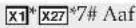 |  | Set anti-aliasing filter for window X1 to mode X27. |
| Example: 3*4*7# Aaf3*4 Set anti-aliasing filter for | window 3 to auto-adjust. | ||
| View anti-aliasing mode | *** | *** | View anti-aliasing filter for window X1. |
| Baud rate | |||
| Change baud rate | Esc X28 CP Ccp | X28 ← | Change the baud rate to X28. |
Control Software for Windows®
The Windows-based Extron PIP 422 & 444 Control Program, which communicates with the processor via the RS-232/RS-422 port, provides an easy way to configure and operate the PIP. The program is compatible with Windows 2000 and Windows XP.
Installing the software
The program is contained on the Extron Software Products CD-ROM, disk B. Install the software as follows:
NOTE
For full functionality, install both of the following programs:
• The PIP 422 & 444 Control Program
• The Firmware Loader
- Insert the CD-ROM into the drive. The installation program should start automatically. If it does not self-start, run Launch.exe from the CD.
The Extron software CD window appears (figure 4-2).
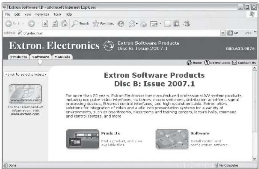
Figure 4-2 — Software CD window
- Click the Software tab (figure 4-2).
- Scroll to the desired program and click Install (figure 4-3).

Figure 4-3 — Software installation
-
Follow the on-screen instructions. By default, the Windows installation of the PIP 422 & 444 Control Program creates a C:\Program Files\Extron\PIP 422 & 444 directory, and it places four icons into a group folder named "Extron Electronics\PIP 422 & 444." The four installed icons are:
-
PIP 422 & 444
- PIP 422 & 444 Help
- Check for PIP 422 & 444 Update
- Uninstall PIP 422 & 444
Starting the control program
To run the software:
- Click Start > Programs > Extron Electronics > PIP 422 & 444 > PIP 422 & 444. The Communication Connection Settings window appears (figure 4-4).

PIP 422 & 444

Figure 4-4 — Communication Connection Settings window
- Select the comm port that is connected to the PIP's remote connector and the baud rate at which the PIP is operating. Click Connect.
NOTE
If you don't want to take this step every time, select the Automatically connect with this setting when it starts up next time check box.
The PIP 422 & 444 program window appears (figure 4-5).

Figure 4-5 — PIP 422 & 444 program window
The program window is divided into three areas: a tool bar on the top of the window, a graphic area on the right side of the window, and a controls area on the left side of the window.
Tool bar
The tool bar (figure 4-6) provides a number of buttons that provide shortcuts for common tasks such as connecting and disconnecting, saving and recalling the current configuration, uploading new firmware, and system help. Saving and restoring the current configuration and uploading firmware are covered in more detail below.

Figure 4-6 — Tool bar
Open and Save buttons
Any changes that you make to the display, including size, position, border and background color, and selected inputs, can be saved in a file with the extension *.pip. To save the values, click the Save button shown at right. If you haven't already saved the values before, the program prompts you to name the file.
To restore the settings from the *.pip file, click the Open button, shown at right, and select the desired file.


Data trace button
The data trace button calls the trace log window (figure 4-7), which shows the serial communications, in ASCII and Hex, between the controller and the PIP. Reference to this window can be helpful when writing your own control scripts.

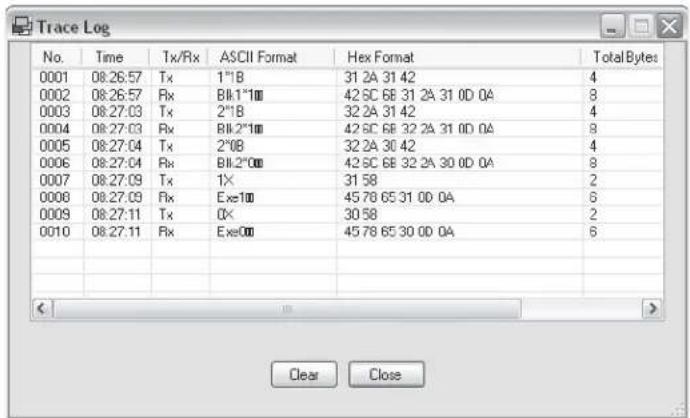
Figure 4-7 — Trace log window
Upgrade firmware button
The firmware upgrade utility provides a way to replace the firmware that is coded on the processor's control board without taking the processor out of service.

NOTE Upgrading the firmware does not overwrite the settings or presets.
Update the processor firmware as follows:
-
Start the PIP 422 & 444 control program and connect to the processor. See "Starting the control program" in this chapter, starting on page 4-10.
-
Visit the Extron web site (www.extron.com), click the Download tab, and select either the PIP 422 or PIP 444. Select the appropriate firmware file to download and copy it to your computer. Note the folder to which you save the firmware file.
-
Click the update firmware button (figure 4-8). The Extron Firmware Loader appears.

Figure 4-8 — Open window
4a. Click Browse. The open file window appears.
4b. Navigate to the folder where you saved the firmware upgrade file. Select the file. The Firmware Loader returns to the top.
NOTE Ensure that the firmware upgrade is for the PIP.
NOTE Valid PIP firmware files must have the file extension ".pkg". Any other file extension is not a firmware upgrade for your PIP.
4c. Click Upload. The File Loader reports, "This process could take several minutes. Please wait..." and then displays a scroll bar that shows the status of the upload.
4c. When the Firmware Loader reports, "Transfer complete!", click Exit.
NOTE If the firmware loader utility exits before the status bar has progressed completely across the indicator window, try using a control cable with only pins 2, 3, and 5 connected. If necessary, modify the cable by removing pins or cutting wires.
Check for software updates button
This button forces the controlling computer, if connected to the Internet, to check the Extron Web site to see if any firmware update (firmware of a version newer than that installed in the PIP) is available for the PIP. If a newer firmware version is available, the program prompts you to download and install the firmware.
Graphic area

The graphic area (figure 4-9) represents the PIP's video output and the associated four (PIP 444) or two (PIP 422) picture-in-picture windows.

Figure 4-9 — Graphic area
- To resize a window, click an anchor point ( ■) and drag it to resize the window.
- To move a window, click in the desired window and drag it to the new location.
NOTE To retain the aspect ratio when resizing, select the Lock Aspect Ratio checkbox.
NOTE If you have dragged a window so far out of the picture that you have "lost" it, click View > Expanded View to show the entire horizontal and vertical video stream.
- Right click any window area to bring up the image area for the associated window or to execute the center image function.
- Right click outside of the window area to change the border color, background color, or to change the text position and style.
- Double-click any window to activate the image view for that window (indicated in dark blue). To return to the window view, double-click the image again.
Controls area
The controls area, figure 4-10, consists of four tabs, Control, Preset, Picture, and Advanced, that allow you to perform many of the same functions as the PIP's front panel.
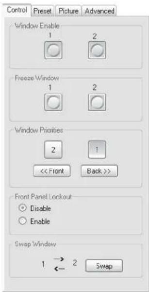
PIP 422

PIP 444
Figure 4-10 — Controls area, Control tab
Control tab
Figure 4-10 shows the controls area with the Control tab selected.
- Windows Enable — Select and deselect a window for display by clicking the associated window's button. A button appears green when selected and the window appears in the graphic area of the screen. A button appears gray when deleselected and the window does not appear in the graphic area.
- Freeze Window — Select and deselect an input to freeze or unfreeze that input's window in the displayed image. A button appears red when selected (that input is frozen) and appears gray when deselected (the input video is in motion).
- Window Priorities — Select a window button and click the <
> buttons to reorder the window priorities. The highest priority window is to the left and the lowest priority window is to the right. - Front Panel Lockout — Select the Disable or Enable radio button to unlock (Disable) or lock (Enable) the front panel.
- Swap (PIP 422 only) — Click the Swap button to exchange the size, position, and priority information between windows 1 and 2.
Preset tab
Figure 4-11 shows the controls area with the Preset tab selected.

Figure 4-11 — Controls area, Preset tab
- Preview — To see a preset's settings without recalling the preset, select the desired preset using the drop box and click the Preview button. The program pops up a window that resembles the graphic area (figure 4-9).
NOTE The graphic area displayed as a result of the Preview function is for display only. The settings cannot be changed on this screen.
- Recall — To recall a preset, select the desired preset using the drop box and click the Recall button. The recalled preset's settings are applied to the output image.
- Save — To save a preset, select the desired preset using the drop box and click the Save button. All of the current settings are saved for later use at the specified preset location.
- Reset — To reset an individual preset, select the desired preset using the drop box and click the Reset button. All of the settings for the selected preset are reset to the factory defaults. See figure 3-11 (PIP 422) or figure 3-12 (PIP 444) in chapter 3, "Operation", to identify the factory defaults.
- Reset All Presets — To reset all presets, click the Reset All Presets button. All of the settings for all presets are reset to the factory defaults. See figure 3-11 (PIP 422) or figure 3-12 (PIP 422) to identify the factory defaults.
Picture tab
Figure 4-12 shows the controls area with the Picture tab selected.

Figure 4-12 — Controls area, Picture tab
- Picture Controls — The picture controls allow you to set the input video format, anti-aliasing filter, color, tint, contrast, brightness, and detail filter for each window. To set a picture control, select the desired window using the Window Select drop box and set the desired value.
- Window controls — The window controls allow you to precisely set the position and size of the window selected in the Window Select drop box. For both Position and Size, the left adjustment is horizontal and the right adjustment is vertical. The + and - buttons resize the window while maintaining the aspect ratio.
NOTE Size and position adjustments are updated live in the graphic area.
- Image controls — The image controls allow you to precisely set the position and size of the image within the window selected by the Window Select drop box. For both Position and Size, the left adjustment is horizontal and the right adjustment is vertical. The + and - buttons resize the image within the window while maintaining the aspect ratio. The Center Image button automatically centers the image within the window.
NOTE Size and position adjustments are updated live in the graphic area.
Advanced tab
Figure 4-13 shows the controls area with the Advanced tab selected.

Figure 4-13 — Controls area, Advanced tab
The Advanced Configuration Settings area has drop boxes that allow you to select:
• The background and border colors
• The insertion effect (cut, wipe, or dissolve)
• The output standard (NTSC, NTSC 0 IRE, or PAL)
• The position of the text that you insert in a window
• The text style (solid or translucent)
The Window Text area allows you to select one of the windows (using the Select Window drop box) and then enter or erase text in the window.
The Reset Unit button restores the factory defaults.
Using the help system
For information about program features, you can access the help program in any of the following ways:
- From the Extron Electronics group folder, click on the PIP Help icon.
- From within the PIP Control Program, click on the Help menu on the main screen.
Appendix A
Specifications and Part Numbers
Specifications
Part Numbers
Specifications and Part Numbers
Video
Gain .... Unity
Differential phase error .... 1.5° at 3.58 MHz and 4.43 MHz
Differential gain error .... 1.5% at 3.58 MHz and 4.43 MHz
Video input and loop-through
Number/signal type
PIP 444.... 4 component video, S-video, composite video inputs
4 identical, buffered loop-throughs
PIP 422.... 2 component video, S-video, composite video inputs
2 identical, buffered loop-throughs
Connectors
PIP 444 ...... 4 x 3 female BNC for inputs
4 x 3 female BNC for loop-throughs
PIP 422 ...... 2 x 3 female BNC for inputs
2 x 3 female BNC for loop-throughs
Nominal level .... 1 Vp-p for Y of component video and S-video
1 Vp-p for composite video
0.7 Vp-p for R-Y and B-Y of component video
0.7 V p-p for C of S-video
Minimum/maximum levels ..... 0.3 V to 2.0 V p-p with no offset
Impedance 75 ohms
Horizontal/vertical frequency .. NTSC 3.58, NTSC 4.43, PAL, SECAM
Resolution range .... NTSC 3.58, NTSC 4.43, PAL, SECAM
Return loss .... < -30 dB @ 5 MHz
DC offset (min./max.)....-0.3 V to +1.3 V
External sync (genlock).... 0.3 V to 1.0 Vp-p
Video processing
Encoder 10 bit digital
Digital sampling .... 24 bit, 8 bits per color; 80 MHz standard
Colors 16.8 million
Anti-aliasing filtering .... 5 levels: 0 (off), 1, 2, 3, auto (which uses 0-3)
Detail filtering .... 16 levels: 0-7, 8 (no filtering), 9-15
Video output
Number/signal type ...... 1 component video
1 S-video
1 composite video
Connectors 3 female BNC for component video
2 female BNC for S-video
1 female BNC for composite video
Nominal level .... 1 Vp-p for Y of component video and S-video
1 Vp-p for composite video
0.7 Vp-p for R-Y and B-Y of component video
0.7 V p-p for C of S-video
Minimum/maximum levels ..... 0.0 V to 1.0 Vp-p
Impedance 75 ohms
DC offset 350 ± 25 mV (max.) with input at 0 offset (for Y of component and S-video and for composite video)
650 ±25 mV (max.) with input at 0 offset (for R-Y and B-Y of component video and for C of S-video)
Sync
Genlock connectors (PIP 444) .... 1 BNC female for genlock input 1 BNC female for genlock output (terminate with 75 ohms if unused)
Standards
Input ...... NTSC 3.58, NTSC 4.43, PAL, SECAM
Output ...... NTSC 3.58, PAL
Control/remote — processor
Serial control port ...... RS-232 or RS-422, 9-pin female D connector
Baud rate and protocol .... 115200, 38400, 19200, or 9600 (default) baud (configurable); 8 data bits; 1 stop bit; no parity
Serial control pin configurations RS-232: 2 = TX, 3 = RX, 5 = GND RS-422: 2 = TX-, 3 = RX-, 5 = GND, 7 = Rx+, 8 = Tx+
Program control .... Extron's control/configuration program for Windows ^® Extron's Simple Instruction Set (SIS ^™ )
General
Power 100 VAC to 240 VAC, 50/60 Hz, 10 watts, internal, autoswitchable
Temperature/humidity .... Storage: -40 to +158 °F (-40 to +70 °C) / 10% to 90%, noncondensing Operating: +32 to +122 °F (0 to +50 °C) / 10% to 90%, noncondensing
Rack mount..... Yes, with included brackets
Enclosure type.... Metal
Enclosure dimensions .... 1.75" H x 17.5" W x 8.5" D (1U high, full rack wide) 4.4 cm H x 44.4 cm W x 21.6 cm D (Depth excludes connectors and knobs. Width excludes rack ears.)
Product weight.... 7.0 lbs (3.2 kg)
Shipping weight 10 lbs (5 kg)
Vibration ...... ISTA 1A in carton (International Safe Transit Association)
Listings UL, CUL
Compliances ...... CE, FCC Class A, VCCI, AS/NZS, ICES
MTBF 30,000 hours
Warranty 3 years parts and labor
NOTE All nominal levels are at ±10%.
NOTE Specifications are subject to change without notice.
Part Numbers
Included parts
These items are included in each order for a PIP 422 or PIP 444:
| Included parts part number | Replacement |
| PIP 444 60-606-01 | |
| PIP 422 60-607-01 | |
| Rack/desk mounting brackets 70-077-03 | |
| IEC power cord | |
| Rubber feet (self-adhesive) (4) | |
| User's manual | |
| Label holder (self-adhesive) | |
| Extron Software Products CD, disk B |
Accessories
These items may be ordered separately:
| Accessories Part number |
| MBD 149 Under-desk mounting kit 70-077-03 |
| SVHSF-BNCM 1' adapter 26-541-02 |
| SVHSM-BNCM 1' adapter 26-353-02 |
| SVHSM-BNCM 3' adapter 26-353-03 |
| SVHSM-BNCM 6' adapter 26-353-04 |
| SVHSM-BNCF 8" adapter 26-353-01 |
FCC Class A Notice
Note: This equipment has been tested and found to comply with the limits for a Class A digital device, pursuant to part 15 of the FCC Rules. These limits are designed to provide reasonable protection against harmful interference when the equipment is operated in a commercial environment. This equipment generates, uses and can radiate radio frequency energy and, if not installed and used in accordance with the instruction manual, may cause harmful interference to radio communications. Operation of this equipment in a residential area is likely to cause harmful interference, in which case the user will be required to correct the interference at his own expense.
Note: This unit was tested with shielded cables on the peripheral devices. Shielded cables must be used with the unit to ensure compliance.
Extron's Warranty
Extron Electronics warrants this product against defects in materials and workmanship for a period of three years from the date of purchase. In the event of malfunction during the warranty period attributable directly to faulty workmanship and/or materials, Extron Electronics will, at its option, repair or replace said products or components, to whatever extent it shall deem necessary to restore said product to proper operating condition, provided that it is returned within the warranty period, with proof of purchase and description of malfunction to:
USA, Canada, South America, Europe, Africa, and the Middle East: and Central America: Extron Electronics, Europe
Extron Electronics Beeldschermweg 6C 1001 East Ball Road 3821 AH Amersfoort Anaheim, CA 92805, USA The Netherlands
Asia: Japan:
Extron Electronics, Asia Extron Electronics, Japan
135 Joo Seng Road, #04-01 Kyodo Building
PM Industrial Bldg. 16 Ichibancho
Singapore 368363 Chiyoda-ku, Tokyo 102-0082
Japan
This Limited Warranty does not apply if the fault has been caused by misuse, improper handling care, electrical or mechanical abuse, abnormal operating conditions or non-Extron authorized modification to the product.
If it has been determined that the product is defective, please call Extron and ask for an Applications Engineer at (714) 491-1500 (USA), 31.33.453.4040 (Europe), 65.383.4400 (Asia), or 81.3.3511.7655 (Japan) to receive an RA# (Return Authorization number). This will begin the repair process as quickly as possible.
Units must be returned insured, with shipping charges prepaid. If not insured, you assume the risk of loss or damage during shipment. Returned units must include the serial number and a description of the problem, as well as the name of the person to contact in case there are any questions.
Extron Electronics makes no further warranties either expressed or implied with respect to the product and its quality, performance, merchantability, or fitness for any particular use. In no event will Extron Electronics be liable for direct, indirect, or consequential damages resulting from any defect in this product even if Extron Electronics has been advised of such damage.
Please note that laws vary from state to state and country to country, and that some provisions of this warranty may not apply to you.

www.cxtron.com
Extron Electronics, USA
1230 South Lewis Street
Anaheim, CA 92805
800.633.9876 714.491.1500
FAX 714.491.1517
Extron Electronics, Europe
Beeldschermweg 6C
3821 AH Amersfoort, The Netherlands
+800.3987.6673 +31.33.453.4040
FAX +31.33.453.4050
Extron Electronics, Asia
135 Joo Seng Rd. #04-01
PM Industrial Bldg., Singapore 368363
+800.7339.8766 +65.6383.4400
FAX +65.6383.4664
Extron Electronics, Japan
Kyodo Building, 16 Ichibancho
Chiyoda-ku, Tokyo 102-0082
Japan
+81.3.3511.7655 FAX +81.3.3511.7656


- PIP 422 and PIP 444
- Picture-in-Picture Video Processors
- Safety Instructions • English
- Caution
- Avertissement
- Quick Start — PIP 422 and PIP 444
- Installation
- Step 1
- Step 2
- Step 3
- Step 4
- Step 5
- Step 6 (PIP 444 only)
- Quick Start — PIP 422 and PIP 444, cont'd
- Step 7
- Step 8
- Using the Menu System
- Setup and Operation Configure the inputs
- Configure the output
- Select a preset (PIP size and position)
- Table of Contents
- Chapter 1 • Introduction ...... 1-1
- Chapter 2 • Installation ...... 2-1
- Mounting the Processor 2-2
- Rear Panel Connections 2-5
- Setting Up Genlock and Vertical Interval Switching....2-7
- Chapter 3 • Operation .... 3-1
- Power-on Indicators 3-4
- Menu System....3-5
- Picture Controls 3-10
- Window Presets 3-13
- Additional Functions 3-15
- Optimizing the Image 3-17
- Table of Contents, cont'd
- Chapter 4 • Remote Control .... 4-1
- Simple Instruction Set Control 4-2
- Control Software for Windows ® 4-10
- Appendix • Specifications and Part Numbers ...... A-1
- Specifications ...... A-2
- Part Numbers ...... A-4
- Chapter One
- Introduction
- About the Picture-in-Picture Processors
- Features
- Chapter Two
- Mounting the Processor
- UL requirements
- Rack mounting
- Table or wall mounting
- Through-desk mounting
- Rear Panel Connections
- NOTE
- Setting Up Genlock and Vertical Interval Switching
- Genlock setup
- Oscilloscope displays
- Chapter Three
- Operation
- Front Panel Features
- NOTE Tint control is not available for PAL inputs.
- Power-on Indications
- Menu System
- Menu system overview
- Input Configuration menu
- Output Configuration menu
- Advanced Configuration menu
- Border Color submenu
- Background Color submenu
- Window Effect submenu
- Window Priority submenu
- Temperature submenu
- Genlock Configuration menu (PIP 444 only)
- Exit menu
- Picture Controls
- Figure 3-10 — Picture controls flowchart
- Auto-center the image
- Window Presets
- Recall a preset
- Save the current window settings as a preset
- Additional Functions
- Freeze mode
- Front panel security lockout (Executive mode)
- Unit reset
- Selecting the baud rate and RS-232/RS-422 protocol
- Optimizing the Image
- Chapter Four
- Remote Control
- Simple Instruction Set Control
- Host-to-PIP communications
- PIP-initiated messages
- Error responses
- Using the command/response tables
- Symbol Definitions
- Command/response table for special function SIS commands
- Command/response table for special function SIS commands (cont'd)
- Control Software for Windows®
- Installing the software
- Starting the control program
- Tool bar
- Open and Save buttons
- Data trace button
- Upgrade firmware button
- Check for software updates button
- Graphic area
- Controls area
- Control tab
- Preset tab
- Picture tab
- Advanced tab
- Using the help system
- Appendix A
- Specifications and Part Numbers
- Video
- Video input and loop-through
- Video processing
- Video output
- Sync
- Control/remote — processor
- General
- Part Numbers
- Included parts
- Accessories
- FCC Class A Notice
- Extron's Warranty
- Asia: Japan:
Brand : Extron
Model : PIP 422
Category : Processor