VINX-110-HDMI-DEC - Audio/video extender Lightware - Free user manual and instructions
Find the device manual for free VINX-110-HDMI-DEC Lightware in PDF.


User questions about VINX-110-HDMI-DEC Lightware
0 question about this device. Answer the ones you know or ask your own.
Ask a new question about this device
Download the instructions for your Audio/video extender in PDF format for free! Find your manual VINX-110-HDMI-DEC - Lightware and take your electronic device back in hand. On this page are published all the documents necessary for the use of your device. VINX-110-HDMI-DEC by Lightware.
USER MANUAL VINX-110-HDMI-DEC Lightware
Important Safety Instructions
Class II apparatus construction.
The equipment should be operated only from the power source indicated on the product.
To disconnect the equipment safely from power, remove the power cord from the rear of the equipment, or from the power source. The MAINS plug is used as the disconnect device, the disconnect device shall remain readily operable.
There are no user-serviceable parts inside of the unit. Removal of the cover will expose dangerous voltages. To avoid personal injury, do not remove the cover. Do not operate the unit without the cover installed.
The appliance must be safely connected to multimedia systems. Follow instructions described in this manual.
Ventilation
For the correct ventilation and to avoid overheating ensure enough free space around the appliance. Do not cover the appliance, let the ventilation holes free and never block or bypass the ventilators (if any).
WARNING
To prevent injury, the apparatus is recommended to securely attach to the floor/wall or mount in accordance with the installation instructions. The apparatus shall not be exposed to dripping or splashing and that no objects filled with liquids, such as vases, shall be placed on the apparatus. No naked flame sources, such as lighted candles, should be placed on the apparatus.
Waste Electrical & Electronic Equipment WEEE
This marking shown on the product or its literature, indicates that it should not be disposed with other household wastes at the end of its working life. To prevent possible harm to the environment or human health from uncontrolled waste disposal, please separate this from other types of wastes and recycle it responsibly to promote the sustainable reuse of material resources. Household users should contact either the retailer where they purchased this product, or their local government office, for details of where and how they can take this item for environmentally safe recycling. Business users should contact their supplier and check the terms and conditions of the purchase contract. This product should not be mixed with other commercial wastes for disposal.
Common Safety Symbols
| Symbol Description | |
| — — — | Direct current |
| ~ | Alternating current |
| Double insulation | |
| Caution: for indoor use only | |
| Caution: possibility of eletric shock | |
| Caution | |


VINX-1x0-HDMI Extenders - User's Manual 3
Symbol Legend
The following symbols and markings are used in the document:
WARNING! Safety-related information which is highly recommended to read and keep in every case!
ATTENTION! Useful information to perform a successful procedure; it is recommended to read.
INFO: A notice which may contain additional information. Procedure can be successful without reading it.
DEFINITION: The short description of a feature or a function.
TIPS AND TRICKS: Ideas which you may have not known yet but can be useful.
Navigation Buttons
Go back to the previous page. If you clicked on a link previously, you can go back to the source page by pressing the button.
Navigate to the Table of Contents.
Step back one page.
Step forward to the next page.
Document Information
All presented functions refer to the indicated products. The descriptions have been made during testing these functions in accordance with the indicated Hardware/Firmware/Software environment:
| Item Version | |
| Core version 1.3.0 | |
| Web version 1.3.0 | |
| Firmware package version 1.3.0 | |
| Lightware Device Controller 1.26.1 |
Document revision: 1.5
Release date: 11-01-2019
Editor: Laszlo Zsedenyi
Table of Contents
- INTRODUCTION....6
1.1.DESCRIPTION 6
1.2. BOX CONTENTS 6
1.3. OPTIONAL ACCESSORIES ....6 1.4. FEATURES OF THE DEVICE ....7
1.5. TYPICAL APPLICATION 7 - INSTALLATION....8
2.1.MOUNTING OPTIONS 8
2.1.1. VESA100 Mounting Adapter for Extenders....8
2.1.2. Rack Shelf Mounting 8
2.2. MOUNTING INTO THE POWERED RACKMOUNT CAGE....9
2.2.1 Features 9
2.2.2. Assembling Steps....9
2.3. CONNECTING STEPS....10 7.3.1. Reasoning the Network: 10
2.3.1. Preparing the Network 10 2.3.2. LAN Connection (Multicost Mode) 10
2.3.2. LAN Connection (Multicast Mode)....10 2.3.3. Further Steps....10
2.3.3.Further Steps 10
3.1. VINX ENCODER FRONT AND REAR VIEW 11
3.2. VINX DECODER FRONT AND REAR VIEW 11
3.3.ELECTRICAL CONNECTIONS....12
3.4. FRONT PANEL LEDS 12
3.5. DIP SWITCH....12 3.6. VINY DRIVER CONVER...13
3.0. VINX DEVICE CONCEPT 12 3.7. VIDEO INTERFACE 13
3.7.1. One-to-one Video Transmission (Unicast Mode) 13
3.7.2. One-to-All Video Transmission (Multicast Mode) 13
3.7.3. Layout Examples 14
3.9.RS-232 INTERFACE 15 - SOFTWARE CONTROL OPTIONS....16
4.1. CONNECTION METHODS....16
4.2. CONNECTING VIA THE BUILT-IN WEB PAGE 16
4.3. CONNECTING USING LIGHTWARE DEVICE CONTROLLER 16
4.3.1. Installation 16
4.3.2. Upgrading the LDC.... 16
4.3.3. Establishing the Connection 17
4.4. THE MAIN WINDOW....18
4.4.1 General Settings 18 4.4.2 Video Status and Settings (Encoder) 10
4.4.2. Video Status and Settings (Encoder) 19 4.4.3. Video Status and Settings (Decoder) 20
4.4.3. Video Status and Settings (Decoder) 20
4.4.4. Network Settings 20
4.5. CROSSPOINT MENU 21
4.5.1. Frame Detector 22
4.6. EDID MENU 22
4.6.1. The EDID Memory Structure 22
4.6.2. EDID Operations.... 23
4.7. ADVANCED SETTINGS....24 4.7.1. Common Settings (Frames and Records)....04
4.7.1. Common Settings (Encoder and Decoder) 24
4.7.2. Decoder-related Settings 25
4.7.3. LW3 Terminal 26
4.8.1 Creating a Video Wall 27
4.8.1. Creating a video wall....27 4.8.2. Identify the Deenders....28
4.8.2. Identify the Decoders 28 4.8.3. Can and Roze Settings 28
4.8.3. Gap and Bezel Settings 28 4.8.4. Modifying a Video Wall 29
4.8.4. Modifying a Video Wall .... 28 4.8.5. Deleting a Video Wall .... 28
4.0.0. Deleting a Video Wall .... 20
- PROGRAMMERS' REFERENCE 29
5.1. OVERVIEW....29
5.2. PROTOCOL RULES 29
5.2.1. The LW3 Tree Structure 29
5.2.2. The LW3 Command Structure.... 29
5.2.3. Legend for the Control Commands....29
5.2.4. General Rules 29
5.2.5. Command Types 30
5.2.6. Prefix Summary 30
5.2.7. Error Messages.... 30
5.2.8. Escaping 30
5.2.9. Subscription 30
5.2.10. Signature....31 5.2.11. Notifications about the Changes of the Properties....64
5.2.11. Notifications about the Changes of the Properties 31
5.3. SYSTEM COMMANDS....31
5.3.1. Querying the Product Name .... 31
5.3.2. Setting the Device Label 31
5.3.3. Querying the Serial Number 31
5.3.4. Querying the Firmware Version 32
5.3.5. Querying the Core Version 32
5.3.6. Resetting the Device.... 32 5.9.7. Resetting the Features Default Options.... 20
5.3.7. Restoring the Factory Default Settings 32
5.4. NETWORK CONFIGURATION....32
5.4.1. Querying the IP Address.... 32
5.4.2. Querying the DHCP State 32
5.4.3. Setting the DHCP State 33
5.4.4. Setting a Static IP Address 33
5.4.5. Querying the Subnet Mask 33
5.4.6. Setting a Static Subnet Mask 33
5.4.7. Querying the Gateway Address 33
5.4.8. Setting a Static Gateway Address 33
5.5. ENCODER-RELATED COMMANDS 34
5.5.1. Querying the Input Video Signal Presence....34
5.5.2. Querying the Resolution of the Input Video Signal....34
5.5.3. Querying the Video Quality Mode 34
5.5.4. Setting the Video Quality Mode 34
5.5.5. Querying the HDCP State 35
5.5.6. Setting the HDCP State 35
5.6. DECODER-RELATED COMMANDS 35
5.6.1. Querying the Resolution of the Output Video Signal 35
5.6.2. Querying the Scaling Mode of the Output Video Signal....35
5.6.3. Setting the Scaling Mode of the Output Video Signal 35
5.6.4. Setting the Resolution of the Output Video Signal 36
5.6.5. Querying the Signal Type of the Output Video Signal 36
5.6.6. Setting the Signal Type of the Output Video Signal....36
5.6.7. Querying the State of the USB Connection 36
5.6.8. Establishing the USB Connection 36
5.7. SERIAL PORT SETTINGS....37
5.7.1. Setting the Port Availability....37
5.7.2. Setting the Baud Rate of the Port 37
5.7.3. Setting the RS-232 Port Mode 37
5.7.4. Setting the Data Bits....37
5.7.5. Setting the Stop Bits....38
5.7.6. Setting the Parity 38
5.8. ARRANGING THE EXTENDERS TO GROUPS....38
5.8.1. Querying the Working Mode (Unicast/Multicast)....38
5.8.2. Setting the Working Mode (Unicast/Multicast)....38
5.8.3. Querying the Video Stream ID Setting Method....39
5.8.4. Querying the DIP Switch Value 39
5.8.5. Querying the Video Stream ID....39
5.8.6. DIP Switch Enable 39
5.8.7. Setting the Video Stream ID 39
5.9. VIDEO WALL SETTINGS....40
5.9.1. Setting the Name of the Video Wall 40
5.9.2. Assigning a Decoder to a Video Wall 40
5.10. SETTING UP A VIDEO WALL (EXAMPLE) 41
5.11. CROSSPOINT SWITCHING EXAMPLES 42
5.11.1. Switching an Input to an Output 42
5.11.2. Switching an input to all Outputs 42
5.11.3. Switching the Source of a Video Wall 42
5.11.4. Multiple Switching 42


VINX-1x0-HDMI Extenders - User's Manual 5
5.12. EDID MANAGEMENT (ENCODER)....43
5.12.1. Querying the Emulated EDID....43
5.12.2. Setting the Emulated EDID on the Input Port....43
5.12.3. Copying an EDID 43
5.12.4. Querying the Preferred Resolution of an EDID.... 43
5.12.5. Deleting an EDID from the User Memory 44
5.13. LW3 COMMANDS - QUICK SUMMARY 45
- FIRMWARE UPGRADE 47
6.1. BUILT-IN WEB OR LDU2....47
6.2. IMPORTANT NOTICES - BEFORE STARTING THE UPGRADE ....47
6.3. ABOUT THE FIRMWARE PACKAGE (LFP/LFP2 FILE) 47
6.4. OPTION 1. - UPGRADING VIA THE BUILT-IN WEB PAGE ....47
6.4.1.Firmware Upgrading Steps 48
6.5. OPTION 2. - UPGRADING BY LDU2....49
6.5.1. Installation 49
6.5.2. Before Starting the Upgrade 49
6.5.3. Firmware Upgrading Steps 50
-
TROUBLESHOOTING....51
-
TECHNOLOGIES....52
8.1. EDID MANAGEMENT....52
8.1.1. Understanding the EDID 52
8.1.2. Advanced EDID Management 52
8.3.1. Protected and Unprotected Content 53
8.3.2. Disable Unnecessary Encryption 53
- APPENDIX ....54
9.1. SPECIFICATIONS 54
9.2. MECHANICAL DRAWINGS....55
9.3. OUTPUT RESOLUTIONS (SCALER) 56
9.4. FACTORY DEFAULT SETTINGS....56
9.5. FACTORY EDID LIST....57
9.6. DIP SWITCH STATES....57
9.7. APPLICATION NOTE (LW-AN-001) 58
9.8. FURTHER INFORMATION....60
1
Introduction
Thank you for choosing Lightware's VINX Video Network Extender devices. In the first chapter we would like to introduce the device by highlighting the most important features in the below listed sections:
DESCRIPTION
BOX CONTENTS
OPTIONAL ACCESSORIES
FEATURES OF THE DEVICE
TYPICAL APPLICATION
1.1. Description
VINX-120-HDMI-ENC and VINX-110-HDMI-DEC are LAN-based Encoder/Decoder multimedia extenders to extend HDMI video from a local source to a remote sink. The Encoder and Decoder devices connect either via a direct CATx cable connection or through a Gigabit Ethernet Switch in between. The maximum delivery distance can reach up to 100 m with minimal latency and employing a quality, proprietary wavelet transform based image compression.
The maximum supported resolution is 3840 x 2160 @ 30Hz with 7.1 audio. The devices support both static and dynamic (DHCP) IP address settings. Pre-programmed factory EDID presets and user EDIDs are stored in the Encoder.
Devices feature embedded web for control.
DIP switches serve quick manual setting for device pairing over the network, a quick and easy installation method. Gap and bezel compensation can be adjusted for video walls. Scaling is available on the receiver side and videos can be freely cropped.
Model Denomination
1x input Type of the A/V interface
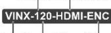
Product Series 2x outputs Type of the extender
1.2. Box Contents
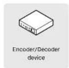
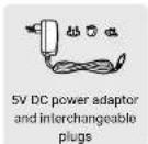

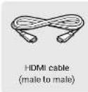
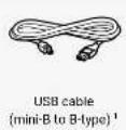
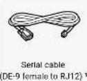
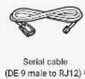
^1 Supplied with the Encoder ^2 Supplied with the Decoder
1.3. Optional Accessories


1.4. Features of the Device

Video Wall Application
The VINX devices can be arranged to a Video wall up to 8x8 Display devices. The displayed video can be the same on each display, one image enlarged to all the sinks, or the mixture of these.

Supporting 4K Resolution
Up to HDMI 2.0 4K 2160p@60Hz 4:2:0 video input or 3840 x 2160 @ 30Hz resolution over a 1 Gigabit network with very low latency.

3D Signal Support
The extenders support the transmission of 3D content in 'Side-by-side' and 'Top-to-bottom' modes.

Advanced EDID Management
The user can emulate any EDID on the inputs independently, read out and store any attached monitor's EDID in the User memory locations, upload and download EDID files.

Local HDMI Output
A display device can be connected to the Encoder for local signal checking. The port carries the same video as the transmitted signal.

Frame Detector and Signal Analysis
The exact video and audio signal format can be determined such as timing, frequencies, scan mode, HDCP encryption, color range, color space and audio sample rate.

Scaling the Output Image
Scaling is available at the Decoder side and videos can be freely cropped.

Image Adjustment
The extended video can be rotated or flipped at the Decoder side.

Built-in Website
Easy access from a web browser to control and configure the devices – even with a mobile device.

USB Extension
KVM extension for USB HID (Human Interface Devices, e.g. keyboard, mouse, presenter) and Mass Storage devices (Flash drive, Hard drive).

Serial Data Transmission
Transparent serial data transmission is available between the endpoints: Encoder and Decoder devices.
1.5. Typical Application
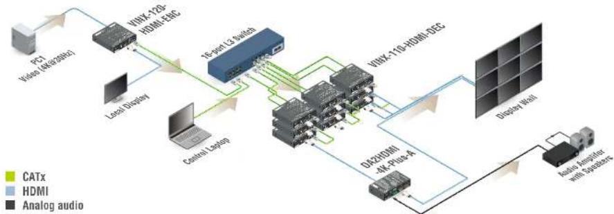
flowchart
graph TD
    A["PCF Video (4K+26Hz)"] --> B["VINK-120 HDMI EBC"]
    C["Local Display"] --> B
    D["Control S Delay"] --> B
    B --> E["Te-joint L3 Switch"]
    E --> F["VINK-110 HDMI DSC"]
    F --> G["Display Wall"]
    G --> H["Analog Amplifier with Suppliers"]
    H --> I["DUR9DMI 4K-Plug-4"]
    I --> E
    style A fill:#f9f,stroke:#333
    style C fill:#ccf,stroke:#333
    style D fill:#cfc,stroke:#333
    style E fill:#fcc,stroke:#333
    style F fill:#cff,stroke:#333
    style G fill:#ffc,stroke:#333
    style H fill:#cfc,stroke:#333
    style I fill:#fcc,stroke:#333
2
Installation
The chapter is about the installation of the device and connecting to other appliances, presenting also the mounting options and further assembly steps.
▶ MOUNTING OPTIONS
MOUNTING BY THE POWERED RACKMOUNT CAGE
CONNECTING STEPS
2.1. Mounting Options
INFO: In order to get the necessary mounting accessory please contact sales@lightware.com.
2.1.1. VESA100 Mounting Adapter for Extenders
Mounting under the Desk
Two pieces of the adapter is needed for this kind of mounting. Fasten the adapters to the bottom of the extender and the desk as shown in the figure:
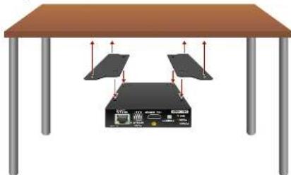
natural_image
Illustration of a server rack with two panels mounted on a table, no text or symbols presentMounting to a Display Device
Two mounting holes can be found on the bottom of the extender at each side, the VESA-compatible accessory plate can be fixed as indicated. The other two holes of the plate can be fixed to a VESA-compatible device (e.g. rear panel of an HDTV).
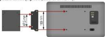
text_image
67.5 mm 100 mmVINX Device (bottom view)
VESA100
Mounting adapter
HDTV (rear view)
2.1.2. Rack Shelf Mounting
The 1U high rack shelf provides mounting holes for fastening four VINX devices and put them into a standard rack cabinet (width of the Rack shelf is 448 mm - without the ears). Fix the device to the Rack shelf as shown in the figure:
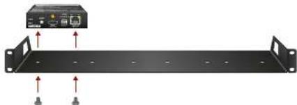
natural_image
Front view of a black rack-mounted server unit with two connectors and an attached network device (no visible text or labels)2.1.3. UD-kit Mounting
Mounting with UD-kit (Under Desk)
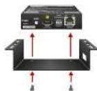
Mounting with UD-kit double (Under Desk Double)
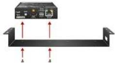
2.2. Mounting into the Powered Rackmount Cage
The PRC-16-205 rackmount cage can be used to install up to 16 VINX devices in the same cabinet.
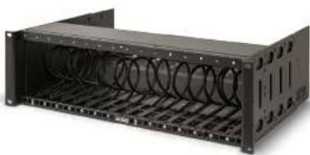
natural_image
Exterior view of a black server rack unit with coiled spring and ventilation slots (no text or symbols visible)2.2.1. Features
- 16 slots for VINX devices in any combination for Encoders and Decoders.
• Built-in power supply unit for the devices. - Easy to install as the cage is rack mountable: 3U-high and 1U-wide.
- The built-in blowers ensure the proper ventilation and airflow.
- The structure of the cage allows different arrangements not only for VINX devices.
For further information please see the Quick Start Guide of the Rackmount Cage.
2.2.2. Assembling Steps
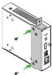
Step 1. Assembling the extender bracket.
Fasten the mounting bracket (highlighted with grey) onto the bottom of the extender with the provided M3x5mm PH flat head black screws (2 pcs./bracket) with a PH1 screwdriver.
Required screw:

M3x5, PH, flat head, black
natural_image
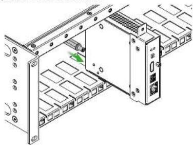
Illustration of an electronic device with ports and connectors, showing no text or symbolsStep 2. 5V DC power cable connection.
Pull out the 5V DC power cable (highlighted with grey) belongs to the desired slot from the enclosure and connect it to the power connector of the extender.
natural_image
Technical diagram of a rack-mounted server unit with a central switch and mounting bracket (no text or symbols visible)Step 3. Fastening the extender in the mounting slot.
Place the extender (highlighted with grey) to the desired mounting slot and fasten the extender bracket with 1 pc M4x8mm PH, D head unpainted screw with a PH1 screwdriver. Pay attention to the guide rails of the cage when placing the extender.
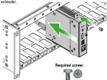
text_image
extender. Required screw:M4x8, PH, D head, unpainted
Step 4. Assembly of the Rack Ears and the Cable Guides
The structure of the rack ears and the cable guides allow three kinds of installations in the Powered Rackmount Cage. The rack ears (highlighted with blue) are assembled to the front side in foremost position. Two cable guides (highlighted with green) are assembled to the device, one is to the front side in the middle position, the second one is to the rear side in lower position.
INFO: Below example is recommended if you have a deep rack and you need cabling on the front and the rear side as well.
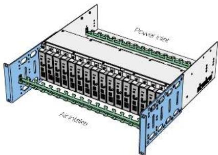
text_image
Power inlet Per-irrigationOther Compatible Devices
The rackmount cage is compatible with other Lightware extenders, too:
• HDMI-OPT-TX100
• HDMI-OPT-TX100R
• HDMI-OPT-TX200R
- HDMI-OPT-RX100
• HDMI-OPT-RX100R
• HDMI-OPT-RX200R
• HDMI-3D-OPT-RX150RA
2.3. Connecting Steps
ATTENTION! Please make sure that the VINX devices within a system run the same firmware version. If the firmwares are different the seamless working is not guaranteed.
2.3.1. Preparing the Network
For the correct installation build a Local Area Network with a Layer 3 (L3) type switch (highly recommended). However, Unicast mode requires only Layer 2 (L2) switch. In both cases the switch must support the Multicast routing.
ATTENTION! VINX Encoder and Decoder send certain system commands over multicast packages. If the multicast routing is disabled on the network, the signal transmission may fail.
Layer 2 vs. Layer 3 Switch
The VINX Encoders and Decoders use multicast routing. The managed switch in the network shall offer the following capabilities:
- IGMPv2
- IGMP snooping
- IGMP fast leave
- IGMP Querier
- Multicast filtering
• 9k MTU - Jumbo/Giant frames
These features are supported by the Layer 3 type switches. Please see more technical information about the network requirements in the Application Note (LW-AN-001) section.
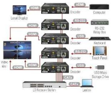
2.3.2. LAN Connection (Multicast Mode)
flowchart
graph TD
    A["Local Display"] --> B["HDMI"]
    B --> C["Encoder"]
    C --> D["Computer"]
    B --> E["HDMI"]
    E --> F["RGB-232"]
    F --> G["Decoder"]
    G --> H["USB"]
    H --> I["Keyboard"]
    I --> J["Touch Panel"]
    B --> K["HDMI"]
    K --> L["RGB-232"]
    L --> M["Decoder"]
    M --> N["USB"]
    N --> O["USB"]
    O --> P["US3 Mass Storage Drive"]
    K --> Q["HDMI"]
    Q --> R["CatX"]
    R --> S["Latency"]
    S --> T["US3 Mass Storage Drive"]
    style A fill:#f9f,stroke:#333
    style B fill:#ccf,stroke:#333
    style K fill:#cfc,stroke:#333
    style L fill:#fcc,stroke:#333
    style M fill:#cff,stroke:#333
    style N fill:#ffc,stroke:#333
    style O fill:#cfc,stroke:#333
    style P fill:#fcc,stroke:#333

Connect a CATx cable between the VINX devices and the L3 Switch.

Connect an HDMI source device (e.g. a computer) to the HDMI input port of the Encoder. Optionally connect a Local Display to the Output port of the Encoder. Connect HDMI display devices to the HDMI output port of the Decoder devices.

Optionally for RS-232 serial transmission: connect the desired devices (e.g. a Touch Control, Relay Box) to the RS-232 ports by the supplied serial cables.

Optionally for USB extension; connect USB devices to the USB ports of the Decoders. Connect the desired host device (e.g. Computer) to the Encoder via the USB mini-B type port. Please pay attention to the indicated port types (USB 1.1 and USB 2.0 support)

Connect the power cord of the supplied adaptor to the DC input first, then to the AC power socket.

Connect a computer to the L3 Switch; thus, you can connect to any VINX extender and arrange the necessary settings easily.
2.3.3. Further Steps
Step1. Connect a computer to the network to arrange the necessary settings easily (see the Connecting via the Built-in Web Page or the Connecting Using Lightware Device Controller section).
Step 2. Group the devices by the DIP switch or via the built-in website (see the Video Status and Settings (Encoder) section).
Step 3. Select the desired Decoder for USB transmission (see the USB Settings (Multicast Mode) section).
ATTENTION! Usually, an Ethernet switch needs more time to be ready after powered on, than the VINX extenders. If the VINX devices and the Ethernet switch are powered on at the same time, the VINX devices may not get IP address and they cannot be accessed over Ethernet. The solution is to power off the VINX devices and power on again.
3
Product Overview
The following sections are about the physical structure of the device, input/output ports and connectors
- VINX ENCODER FRONT AND REAR VIEW
▶ ELECTRICAL CONNECTIONS
FRONT PANEL LEDs
▶ DIP SWITCH
VINX DEVICE CONCEPT
VIDEO INTERFACE
USB INTERFACE
RS-232 INTERFACE
3.1. VINX Encoder Front and Rear View
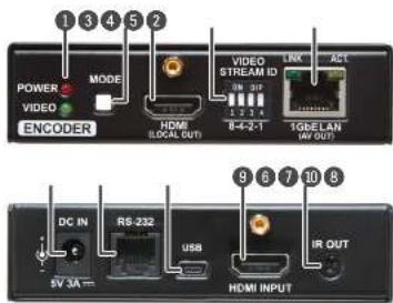
text_image
POWER MODE VIDEO ENCODER VIDEO STREAM ID 8-4-2-1 1GbELAN (AV OUT) DC IN RS-232 USB IR OUT 5V 3A HDMI INPUT1 Status LEDs See the Front Panel LEDs section.
2 Mode Button Short press (less, than 3 sec): switching between Video and Graphics modes. Long press (more, than 3 sec): reset to factory default settings.
3 HDMI Forwarding the same Audio / Video content Output Port as the AV Output Port.
4 DIP Switch Linking Encoder and Decoder devices; for more information see the DIP Switch section.
5 AV Output RJ45 connector for outgoing A/V signal to the Deander device or Network switch
6 DC 5V Input 5V DC input for local power supply.
7 RS-232 Port RJ12 connector for transparent serial communication (point-to-point or point-to-multi point).
USB Port Mini B-type connector for USB pass-through (IP KVM) application.
9 HDMI Input Video port for DVI or HDMI signal. Port
10 IR Output Port IR signal output connector (for 3.5 mm Jack, 3-pole, TRS plug).
WARNING! Always use the supplied 5V power adaptor. Warranty void if damage occurs due to use of a different power source.
3.2. VINX Decoder Front and Rear View
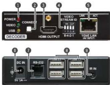
text_image
POWER VIDEO USB DECODER CONNECT HDMI OUTPUT 1 2 3 4 VIDEO STREAM ID 3n 0.2 2 2 4 LINK ACT 8-4-2-1 10GE LAN IN OUTPUT 6 7 8 9 DC IN RS-232 5V 3A ... 5V 7A 5V 1A IR IN1 Status LEDs See the Front Panel LEDs section.
2 Connect Button Short press (less, than 3 sec): acquire USB connection (only in Multicast mode)
Long press (more, than 3 sec): reset to factory default settings.
3 HDMI HDMI output to a sink device.
4 DIP Switch Linking Encoder and Decoder devices; for more information see the DIP Switch section.
5 AV Input RJ45 connector for incoming A/V signal from Port the Encoder device or Network switch.
6 DC 5V Input 5V DC input for local power supply.
7 RS-232 Port RJ12 connector for transparent serial communication (point-to-point or point-to-multi point).
USB Ports USB 1.1 and 2.0 compatible A-type ports for transmitting USB HID devices in Unicast mode. USB 1.1 port can be used for changing the video stream by a keyboard, see the Keyboard Shortcuts section.
9 IR Input Port IR signal input connector (for 3.5 mm Jack, 3-pole, TRS plug).
3.3. Electrical Connections
1 GbE LAN
The devices provide standard RJ45 connectors for outgoing/incoming Video/Control signals. Always use high quality Ethernet cable for connecting Encoders and Decoders.

The Wiring of the Twisted Pair Cables
The recommended termination is based on TIA/EIA T 568 A or TIA/EIA T 568 B standards:
| Pin | TIA/EIA T568 A Wire Color TIA/EIA | T568 B Wire Color | ||
| 1 | white/green white/orange | |||
| 2 | green orange | |||
| 3 | white/orange white/green | |||
| 4 | blue blue | |||
| 5 | white/blue white/blue | |||
| 6 | orange green | |||
| 7 | white/brown white/brown | |||
| 8 | brown brown | |||
HDMI Input and Output Ports
The devices are assembled with standard 19-pole HDMI connectors for inputs and outputs. Special HDMI cables can be fastened to the housing by the

RS-232 Port
The devices contain a standard RJ12 connector which is used for RS-232 serial connection. The port can be used to connect serial devices by using the supplied serial cables. Please see the RS-232 Interface section for more details.

USB Ports
The USB ports allow USB extension. The Encoder is assembled with USB mini-B type port (connecting a computer), and the Decoder device contains two USB 1.1 and two USB 2.0 compatible A-type port. For more information about the USB extension see the USB Interface

3.4. Front Panel LEDs
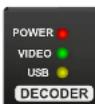
POWER LED
• OFF: the device is not powered.
• BLINKING: booting is in progress.
• ON: the device is powered on.
VIDEO LED
OFF: there is no network connection.
- BLINKING: the device is connected to a network but there is no video stream in progress.
- ON: the device is connected to a network and video stream is in progress.
USB LED (only in Decoders)
- OFF: there is no USB transmission between the Encoder and the Decoder.
- ON: the USB transmission is active between the Encoder and the Decoder.
POWER and VIDEO LEDs (only in Encoders)
- BLINKING together: there is a Video Stream ID clash in the network, e.g. another Encoder is set to the same Video Stream ID.
3.5. DIP Switch
The DIP switch can be used to set the Video Stream ID manually (HW setting). The interpretation of the DIP switch values can be found in the DIP Switch States section; please see the examples below:
| DIP Switch State | Video Stream ID | /SYS/MB/GPIO.DipSwitch value | |
| Set by | Value | ||
| SW setting | see the built-in web | 0x0 | |
| HW setting | 1 | 0x1 | |
| HW setting | 8 | 0x8 | |
3.6. VINX Device Concept
The key feature of the VINX series is the A/V signal transmission from an Encoder to many Decoder devices. The number of the Encoder and Decoder devices is 'limited' to 100 within a system. The video wall can be expanded at a later time, e.g. building a wall with 12 Decoders and add further 12 Decoders later. Another feature is the transmission of RS-232, USB, and Infrared signals.
Unicast Mode (Point-to-Point Connection)
A Decoder is connected to an Encoder device.
Multicast Mode (Point-to-Multi point Connection)
Many Decoder devices are connected to the same Encoder.
The USB transmission is available only at one Encoder-Decoder connection at the same time. The desired device can be activated by the front panel button or via the built-in website.
| Signal | Unicast mode | Multicast mode |
| Audio / Video | E→D | E→D |
| E→D | ||
| USB | E←→D | E←→D |
| E←→D | ||
| RS-232 | E←→D | E←→D |
| E←→D | ||
| IR | E←→D | E←→D |
| E←→D |

Encoder

Decoder
3.7. Video Interface
The following sections describe the modes of the video transmissions. When the necessary network settings are arranged, the followings have to be set:
Video Stream ID Setting
DEFINITION: The Video Stream ID is a four-digit number sequence that identifies a certain stream generated by an Encoder and received by a Decoder.
The Video Stream ID creates the connection between an Encoder and a Decoder. Set the Video stream ID to the same value in the desired VINX devices:
- Use the DIP switch and set a value other than '0000', or
- Set the DIP switch to '0000' and define the ID via the built-in web page, see the Video Status and Settings (Encoder) section, or
- Set the DIP switch to '0000' and define the ID by sending the necessary LW3 command to the device, see the Setting up a Video Wall (Example) section.
INFO: The DIP switch state can be ignored by an LW3 command, see the DIP Switch Enable section.
Unicast/Multicast Mode Setting
DEFINITION: The Unicast mode means an Encoder and a Decoder are connected directly.
DEFINITION: The Multicast mode means Encoder(s) and Decoders are connected via a switch in a Local Area Network (LAN).
Set the desired working mode of the extenders by:
- Selecting the mode via the built-in web page, see the Advanced Settings section, or
- Sending the necessary LW3 command to the device, see the Setting the Working Mode (Unicast/Multicast) section.
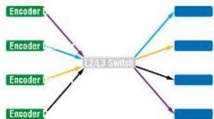
3.7.1. One-to-one Video Transmission (Unicast Mode)
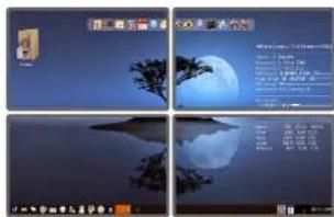
The Encoder and the Decoder devices are arranged in a LAN by connecting them to an L2 or L3 switch. Setting the extenders to Unicast mode it is possible to extend the video signal by an Encoder to a dedicated Decoder.
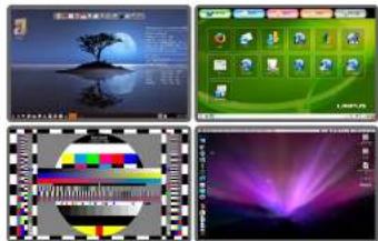
Displayed images of the Sinks connected to the Decoders
text_image
Screenshot of a desktop computer interface displaying four application panels with icons, text, and UI elements.INFO: The Encoder and the Decoder can be connected directly and set to Unicast mode. In this case there is no need an L2/L3 switch but there is no way to communicate with other VINX devices.
3.7.2. One-to-All Video Transmission (Multicast Mode)
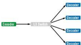
The Encoder and Decoder devices are arranged in a LAN by connecting them to an L3 switch. Setting the extenders to Multicast mode a certain video can be extended from an Encoder to multiple Decoders.
text_image
Four-panel image showing a scenic island with tree silhouette and Chinese text overlays, likely from a presentation or video feed.Video Wall Montage
text_image
Scanned document page with Chinese text, featuring a moon and tree illustration against a dark blue sky background.Tiled Video Wall
3.7.3. Layout Examples
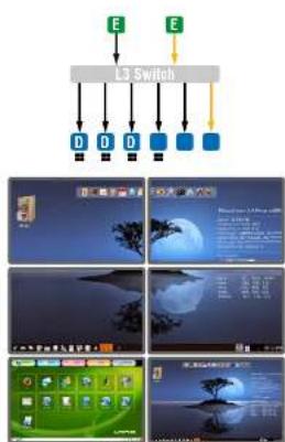
Multicast Mode with Video Wall
The Layout
flowchart
graph TD
    A["L3 Switch"] --> B["D"]
    A --> C["D"]
    A --> D["D"]
    A --> E["D"]
    A --> F["D"]
    A --> G["D"]
    H["Computer System"] --> I["Desktop 1"]
    H --> J["Desktop 2"]
    H --> K["Desktop 3"]
    H --> L["Desktop 4"]
    H --> M["Desktop 5"]
    H --> N["Desktop 6"]
    H --> O["Desktop 7"]
    H --> P["Desktop 8"]
    H --> Q["Desktop 9"]
    H --> R["Desktop 10"]
    H --> S["Desktop 11"]
    H --> T["Desktop 12"]
Features
- 2x2-sized video wall is defined and further two single displays are installed (bottom row).
- Any of the video signals can be displayed on the wall and on a single display device.
• The other video signal can be seen on the other display device. - The video signal on the wall can be changed by using software tools (built-in web or LW3 protocol commands).
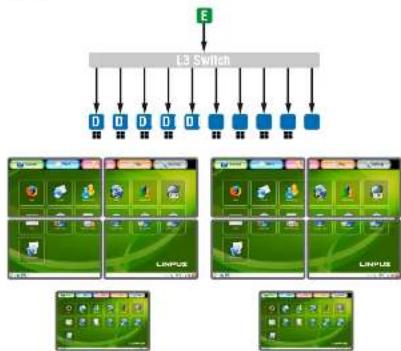
Legend
E Encoder
■ The Decoder is assigned to a Video wall
D Decoder
Two Video Walls and Local Monitors with One Encoder
The Layout
flowchart
graph TD
    E["Input E"] --> L3Switch["L3 Switch"]
    L3Switch --> A1["0"]
    L3Switch --> A2["0"]
    L3Switch --> A3["0"]
    L3Switch --> A4["0"]
    L3Switch --> A5["0"]
    L3Switch --> A6["0"]
    L3Switch --> A7["0"]
    L3Switch --> A8["0"]
    L3Switch --> A9["0"]
    L3Switch --> A10["0"]
    A1 --> B1["L1/NPLUS"]
    A2 --> B2["L1/NPLUS"]
    A3 --> B3["L1/NPLUS"]
    A4 --> B4["L1/NPLUS"]
    A5 --> B5["L1/NPLUS"]
    A6 --> B6["L1/NPLUS"]
    A7 --> B7["L1/NPLUS"]
    A8 --> B8["L1/NPLUS"]
    A9 --> B9["L1/NPLUS"]
    A10 --> B10["L1/NPLUS"]
    A11 --> B11["L1/NPLUS"]
    A12 --> B12["L1/NPLUS"]
    A13 --> B13["L1/NPLUS"]
    A14 --> B14["L1/NPLUS"]
    A15 --> B15["L1/NPLUS"]
    A16 --> B16["L1/NPLUS"]
    A17 --> B17["L1/NPLUS"]
    A18 --> B18["L1/NPLUS"]
    A19 --> B19["L1/NPLUS"]
    A20 --> B20["L1/NPLUS"]
    A21 --> B21["L1/NPLUS"]
    A22 --> B22["L1/NPLUS"]
    A23 --> B23["L1/NPLUS"]
    A24 --> B24["L1/NPLUS"]
    A25 --> B25["L1/NPLUS"]
    A26 --> B26["L1/NPLUS"]
    A27 --> B27["L1/NPLUS"]
    A28 --> B28["L1/NPLUS"]
    A29 --> B29["L1/NPLUS"]
    A30 --> B30["L1/NPLUS"]
    A31 --> B31["L1/NPLUS"]
    A32 --> B32["L1/NPLUS"]
    A33 --> B33["L1/NPLUS"]
    A34 --> B34["L1/NPLUS"]
    A35 --> B35["L1/NPLUS"]
    A36 --> B36["L1/NPLUS"]
    A37 --> B37["L1/NPLUS"]
    A38 --> B38["L1/NPLUS"]
    A39 --> B39["L1/NPLUS"]
    A40 --> B40["L1/NPLUS"]
    A41 --> B41["L1/NPLUS"]
    A42 --> B42["L1/NPLUS"]
    A43 --> B43["L1/NPLUS"]
    A44 --> B44["L1/NPLUS"]
    A45 --> B45["L1/NPLUS"]
    A46 --> B46["L1/NPLUS"]
    A47 --> B47["L1/NPLUS"]
    A48 --> B48["L1/NPLUS"]
    A49 --> B49["L1/NPLUS"]
    A50 --> B50["L1/NPLUS"]
    A51 --> B51["L1/NPLUS"]
    A52 --> B52["L1/NPLUS"]
    A53 --> B53["L1/NPLUS"]
    A54 --> B54["L1/NPLUS"]
    A55 --> B55["L1/NPLUS"]
    A56 --> B56["L1/NPLUS"]
    A57 --> B57["L1/NPLUS"]
    A58 --> B58["L1/NPLUS"]
    A59 --> B59["L1/NPLUS"]
    A60 --> B60["L1/NPLUS"]
    A61 --> B61["L1/NPLUS"]
    A62 --> B62["L1/NPLUS"]
    A63 --> B63["L1/NPLUS"]
    A64 --> B64["L1/NPLUS"]
    A65 --> B65["L1/NPLUS"]
    A66 --> B66["L1/NPLUS"]
    A67 --> B67["L1/NPLUS"]
    A68 --> B68["L1/NPLUS"]
    A69 --> B69["L1/NPLUS"]
    A70 --> B70["L1/NPLUS"]
    A71 --> B71["L1/NPLUS"]
    A72 --> B72["L1/NPLUS"]
    A73 --> B73["L1/NPLUS"]
    A74 --> B74["L1/NPLUS"]
    A75 --> B75["L1/NPLUS"]
    A76 --> B76["L1/NPLUS"]
    A77 --> B77["L1/NPLUS"]
    A78 --> B78["L1/NPLUS"]
    A79 --> B79["L1/NPLUS"]
    A80 --> B80["L1/NPLUS"]
    A81 --> B81["L1/NPLUS"]
    A82 --> B82["L1/NPLUS"]
    A83 --> B83["L1/NPLUS"]
    A84 --> B84["L1/NPLUS"]
    A85 --> B85["L1/NPLUS"]
    A86 --> B86["L1/NPLUS"]
    A87 --> B87["L1/NPLUS"]
    A88 --> B88["L1/NPLUS"]
    A89 --> B89["L1/NPLUS"]
Features
- Two 2x2-sized video walls are defined and further 2 single displays are installed (e.g. the video walls and the local displays are located in different rooms).
- One video signal is displayed on the two video walls and on two local monitors.
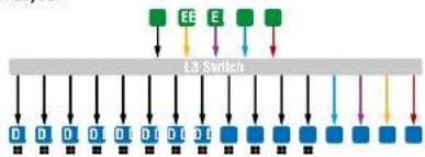
Small View and Large View Combined In Multicast Mode
The Layout
flowchart
graph TD
    A["Input"] --> B["Blue Block"]
    C["Input"] --> D["Blue Block"]
    E["Input"] --> F["Blue Block"]
    G["Input"] --> H["Blue Block"]
    I["Input"] --> J["Blue Block"]
    K["Input"] --> L["Blue Block"]
    M["Input"] --> N["Blue Block"]
    O["Input"] --> P["Blue Block"]
    Q["Input"] --> R["Blue Block"]
    S["Input"] --> T["Blue Block"]
    U["Input"] --> V["Blue Block"]
    W["Input"] --> X["Blue Block"]
    Y["Input"] --> Z["Blue Block"]
    AA["Input"] --> AB["Blue Block"]
    AC["Input"] --> AD["Blue Block"]
    AE["Input"] --> AF["Blue Block"]
    AG["Input"] --> AH["Blue Block"]
    AI["Input"] --> AJ["Blue Block"]
    AK["Input"] --> AL["Blue Block"]
    AM["Input"] --> AN["Blue Block"]
    AO["Input"] --> AP["Blue Block"]
    AQ["Input"] --> AR["Blue Block"]
    AS["Input"] --> AT["Blue Block"]
    AU["Input"] --> AV["Blue Block"]
    AW["Input"] --> AX["Blue Block"]
    AY["Input"] --> AZ["Blue Block"]
    BA["Input"] --> BB["Blue Block"]
    BC["Input"] --> BD["Blue Block"]
    BE["Input"] --> BF["Blue Block"]
    BG["Input"] --> BH["Blue Block"]
    BI["Input"] --> BJ["Blue Block"]
    BK["Input"] --> BL["Blue Block"]
    BM["Input"] --> BN["Blue Block"]
    BO["Input"] --> BP["Blue Block"]
    BQ["Input"] --> BR["Blue Block"]
    BS["Input"] --> BT["Blue Block"]
    BU["Input"] --> BV["Blue Block"]
    BW["Input"] --> BX["Blue Block"]
    BY["Input"] --> BZ["Blue Block"]

text_image
Screenshot of a macOS desktop with multiple application windows and icons, including time, sky, moon, and calendar.Features
- 3x4-sized video wall is defined and further four single displays are installed (bottom row).
- Any of the video signals can be displayed on the wall and on a single display device.
- The other video signals can be seen on the single display devices (bottom row).
- The video signal on the wall can be changed by using software tools (built-in web or LW3 protocol commands).
3.8. USB Interface
USB 1.1 and USB 2.0 data transmission operates between an Encoder and a certain Decoder device. Connect the host device (e.g. a computer) to the Encoder and the USB devices to the Decoder. Supported USB devices:
• USB HID devices: keyboard, mouse, presenter.
• Mass storage devices: USB flash drive, external hard drive.
The transmission works in Unicast and Multicast mode as well, but in latter case, the desired Decoder has to be selected by any of the following ways:
- Pressing the Mode button on the front panel for less, than three seconds (the connected display device will show Starting USB, the other Sinks will show Stopping USB on the screen).
- Pressing the Acquire USB connection button in the Advanced tab on the built-in web page (see the USB Settings (Multicast Mode) section), or
- Sending an LW3 command to the desired Decoder.
The USB devices connected to the other Decoders will be still powered but the data transmission is suspended.
ATTENTION! USB 1.1 ports can be used for the stream changing, see the Keyboard Shortcuts section.
ATTENTION! The active Decoder works like an extended USB hub connected to a computer. Please pay attention to the storage device to remove safely before unplugging it or interrupting during a disc operation.
INFO: The USB transmission is automatically enabled between the Encoder and the Decoder in Unicast mode.
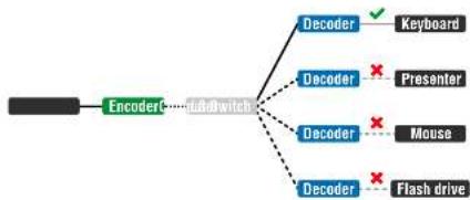
flowchart
graph TD
    A["Encoder"] --> B["Data switch"]
    B --> C["Decoder"]
    B --> D["Decoder"]
    B --> E["Decoder"]
    B --> F["Decoder"]
    C --> G["Keyboard"]
    D --> H["Presenter"]
    E --> I["Mouse"]
    F --> J["Flash drive"]
USB Transmission between an Encoder and a Decoder
3.9. RS-232 Interface
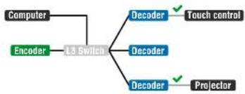
Serial data transmission works between an Encoder and all the connected Decoders which have the same Video Stream ID. This transmission is independent of the current working mode (Unicast/Multicast). To connect serial devices please use the cables supplied with the extenders.
ATTENTION! The serial data is transmitted only if video is transmitted between the affected devices.
Pass-through Mode
DEFINITION: The Pass-through mode means fully transparent bidirectional data transmission from an RS-232 port of a VINX Extender to an RS-232 port of a VINX Decoder - and Vice versa.
All data received from the serial ports of the Decoders is transmitted to the serial port of the Encoder and vice versa: the data received from the serial port of the Encoder is transmitted to the serial ports of all connected Decoders.

RS-232 Data Transmission (Pass-through mode)
Please note that transmitting data between two Decoders is not possible; see the above figure: sending serial data from the Touch Control to the Projector is not possible.
ATTENTION! The data transmission works only if the serial port parameters are set to the same values in all devices: serial data sender/receiver and the VINX Encoder and Decoder devices.
Command Injection Mode
DEFINITION: The Command Injection mode is like an RS-232-TCP/IP bidirectional converter. The mode allows data transmission between a TCP/IP device and a serial device.
When a device is connected to the network (e.g. TCP/IP connection from a computer) and a serial device is connected to the RS-232 port of a VINX device they can communicate with each other.
RS-232 Data Transmission (Command Injection mode)
The mode can be enabled as described in the Setting the RS-232 Port Mode section.
4
Software Control Options
The VINX extenders allow setting all the parameters via a user-friendly interface. Open a web browser (Google Chrome or Mozilla Firefox is highly recommended) and connect to the extender to access the parameters and settings. The other option is to use the Lightware Device Controller (LDC) software and connect to the device without a web browser. The features are described in the coming sections.
▶ CONNECTION METHODS
CONNECTING VIA THE BUILT-IN WEB PAGE
CONNECTING USING LIGHTWARE DEVICE CONTROLLER
THE MAIN WINDOW
▶ CROSSPOINT MENU
▶ EDID MENU
▶ ADVANCED SETTINGS
VIDEO WALL SETUP
TIPS AND TRICKS: To get the best visibility of the screenshots in this chapter adjust the zoom setting of your PDF Reader software to 150% magnification.
4.1. Connection Methods
The software control can be achieved by:
- Opening the built-in web page, or
Using the Lightware Device Controller software.
After establishing the connection, there is no difference between the connection types, the feature and the functions are the same.
4.2. Connecting via the Built-in Web Page
ATTENTION! The supported web browsers are Google Chrome and Mozilla Firefox.
INFO: The default setting of the IP address is dynamic (DHCP).
Step 1. Arrange the desired extenders with source/sink devices. Follow the steps described in the Connecting Steps section.
Step 2. Connect a suitable control device (e.g. computer, mobile device) to the same network.
Step 3. Open the web browser and type the IP address of the desired VINX device in the address line. If the IP address is not known use the MAC address (written on the housing of the device):
a) Connecting to an Encoder: http://lwr-gateway
b) The factory default IP address is Dynamic (DHCP). Check the list of the connected devices (DHCP client list) in the DHCP server and note the IP address (or the MAC address and connect to the device as written in paragraph 'a').
INFO: When you successfully connected to an Encoder, all the other counterpart devices will be listed in the Main settings tab (General section).
4.3. Connecting Using Lightware Device Controller
4.3.1. Installation
Installation for Windows OS
Step 1. Run the installer. If the User Account Control drops a pop-up message click Yes.
Step 2. During the installation you will be prompted to select the type of the installation: normal and the snapshot install:
Normal install Snapshot install
| Available for Windows and macOS Available for Windows | |
| The installer can update only this instance | Cannot be updated |
| Only one updateable instance can exist for all users | Different versions can be installed for all users |
of the Installation Types
ATTENTION! Using the Normal install as the default value is highly recommended.
Installation for macOS
INFO: After the installation, the Windows and the Mac application has the same look and functionality. This type of the installer is equal with the Normal install in case of Windows and results an updateable version with the same attributes.
Mount the DMG file with double clicking on it and drag the LDC icon over the Applications icon to copy the program into the Applications folder. If you want to copy the LDC into another location just drag the icon over the desired folder.
4.3.2. Upgrading the LDC
Step 1. Run the application.
The Device Discovery window appears automatically and the program checks the available updates on Lightware's website and opens the update window if the LDC found updates.
The current and the update version number can be seen at the top of the window and they are shown in this window even with the snapshot install.
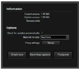
text_image
Information Current version: 1.19.063 Update version: 1.20.065 Browse notes Options Check for updates automatically Remind me later: Next time Proxy settings: Setup Check now Download update Postpone


- Software Control Options VINX 1x0-HDMI Extenders - User's Manual 17
The Update window can be opened manually by clicking the question mark and the Update button.
Step 2. Set the desired update setting in the Options section.
- When the Check for updates automatically option is marked, the LDC tries to find a new version after startup.
- If you want to postpone the update, set the reminder by the drop down list.
- If necessary, the proxy settings are available by clicking the Setup button.
Step 3. Click the Download update button to start the upgrading.
The updates can be checked manually by clicking the Check now button.
4.3.3. Establishing the Connection
Launch the LDC software. The Ethernet tab consists of two lists:
- Favorite Devices: You can add any Lightware device that is connected via Ethernet and no need to browse all the available devices. Devices can be added by pressing the Add button or
- All Devices: The Lightware devices are listed which are available in the connected network.
Select the unit from the discovered Ethernet devices; double click on the device or select it and click on the green Connect button.
Direct Connection by Known IP Address
Format: LightwareDeviceController -i
Example: TightWareDeviceController - i 192.168.0.115:6107
The LDC is connected to a device with the indicated static IP address directly; the Device Discovery window is not displayed.
Further Tools
The Tools menu contains the following options:
- Log Viewer: The tool can be used for reviewing log files which have been saved previously.
- Create EDID: This tool opens the Easy EDID Creator wizard which can be used for creating unique EDIDs in a few simple steps. Functionality is the same as the Easy EDID Creator.
- Demo Mode: This is a virtual MX-FR17 matrix router with full functionality built into the LDC. Functions and options are the same as a real MX-FR17 device.
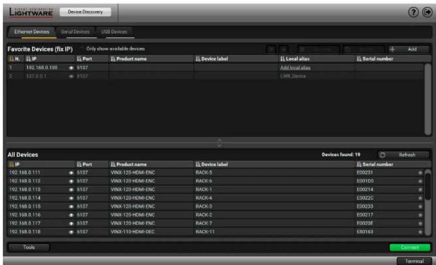
text_image
Lightware Device Discovery Ethernet Devices Serial Devices USD Devices Favorite Devices (fix IP) Only show available devices Add N. IP Part Product name Device label Local alias Serial number 1 192.168.0.100 8107 Add local alias 2 127.6.0.1 8107 LWR_Devce All Devices Devices found: 19 Refresh IP Part Product name Device label Serial number 192.168.0.111 8107 VINX-120-HDMI-ENC RACK-5 E00231 192.168.0.112 8107 VINX-120-HDMI-ENC RACK-8 E001D5 192.168.0.113 8107 VINX-120-HDMI-ENC RACK-1 E00214 192.168.0.114 8107 VINX-120-HDMI-ENC RACK-4 E0022C 192.168.0.115 8107 VINX-120-HDMI-ENC RACK-3 E00233 192.168.0.116 8107 VINX-120-HDMI-ENC RACK-2 E00217 192.168.0.117 8107 VINX-120-HDMI-ENC RACK-7 E0023E 192.168.0.118 8107 VINX-110-HDMI-DEC RACK-11 E80163 Tools Connect TerminalDevice Discovery Window
The Terminal window is also available by pressing its button on the bottom.
TIPS AND TRICKS: Press the VINX drawing in the top left corner to navigate back to the Device Discovery window.


- Software Control Options VINX-1x0-HDMI Extenders - User's Manual 18
4.4. The Main Window
4.4.1. General Settings
Grouping the VINX Extenders
Video Stream ID
The current ID number is shown. The following rules are defined to avoid Video Stream ID conflicts:
- When the DIP switch is in 0000 position the SW setting will be valid or else the HW setting (DIP switch) will be valid.
- When the DIP switch is set back to 0000 the SW setting will inherit the ID (the previous DIP switch value).
- SW setting and HW setting can be combined within the group but in this case the DIP switch value will determine the common Video Stream ID.
INFO: The DIP switch state can be ignored by an LW3 command, see the DIP Switch Enable section.
Decoder Assignment
The list contains the VINX devices which are available within the same subnet. Mark the desired devices to set the same ID.
Device Label
Unique name (up to 32 ASCII characters) can be set which will be visible when the given device is listed in the built-in web page of other VINX devices. Furthermore, the name is listed when browsing the client list of a DHCP server.
ATTENTION! It might happen that two or more Encoders installed in the same system with the same Video Stream ID. That would result display problems (e.g. more mouse cursors are displayed when desktop images are shown). Check the Video Stream ID settings of the Encoders.
ATTENTION! The Video wall setup submenu is not displayed on mobile devices in most cases due to the limitation of these displays.
text_image
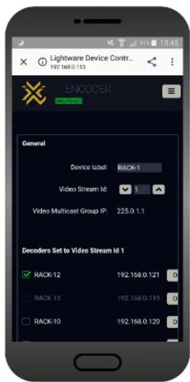
Lightware Device Contr... 192.168.0.113 ENCODER MASCADO General Device label: RACK-1 Video Stream Id: 1 Video Multicast Group IP: 225.0.1.1 Decoders Set to Video Stream Id 1 RACK-12 192.168.0.121 0 RACK-13 192.168.0.119 0 RACK-10 192.168.0.120 0The Main Window of the Built-in Website (Displayed on a Mobile Device)

The current working mode

The Video stream ID is set by the DIP switch

The given Decoder belongs to a video wall

Displaying the Main Menu (if there is not enough space)

Connecting to another device (opened in new tab)


- Software Control Options VINX-1x0-HDMI Extenders - User's Manual 19
4.4.2. Video Status and Settings (Encoder)
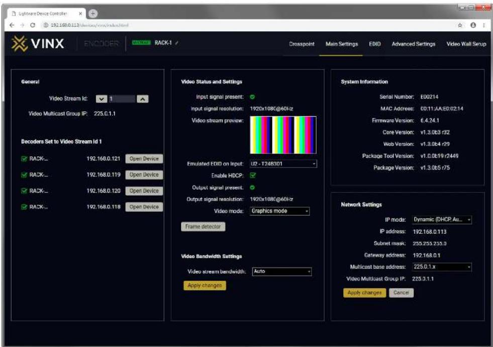
The properties of the incoming and outgoing video signals are displayed with the followings:
- The emulated EDID can be selected (see the EDID Operations section).
- Enable/disable HDCP encryption on the input.
- Selecting the video quality (see below).
- Displaying the Frame Detector in a new window, see the Frame Detector section.
ATTENTION! If the HDCP setting is changed a window will pop up to confirm your selection. The device is restarted automatically when clicking Yes.
ATTENTION! The EDID information cannot be read by the source attached to the HDMI input of an Encoder if HDCP is disabled on the input. That may stop the video transmission in case of certain source devices.
Video Mode
When the network bandwidth is not enough to transmit the video signal the following modes are available in the Encoder:
- Movie mode (Lower image quality @ Less bandwidth): The image quality is adjusted to the available bandwidth. If the bandwidth is decreased the image quality will be lower, but the video streaming is continuous.
- Graphics mode (Best image quality @ High bandwidth): The image quality is kept at a high level. If the bandwidth is decreased the image quality does not change, but frame drop may appear.
The setting has an affect when the available bandwidth is less than required.
Video Bandwidth Settings
A specific bandwidth limitation can be set in the Encoder which affects only the video signal transmission. The following values are available:
Auto / 10 Mbps / 50 Mbps / 100 Mbps / 150 Mbps / 200 Mbps
The Auto selling is the default value which means: the available bandwidth is determined according to current network traffic.
ATTENTION! If the Bandwidth setting is changed a window will pop up to confirm your selection. The device is restarted automatically when clicking Yes.
text_image
VINX ENCODER RACK-1 Crosspoint Main Settings EDIO Advanced Settings Video Wall Setup General Video Stream Id: 1 Video Multicast Group IP: 225.0.1.1 Decoders Set to Video Stream Id 1 RACK... 192.168.0.121 Open Device RACK... 192.168.0.119 Open Device RACK... 192.168.0.120 Open Device RACK... 192.168.0.118 Open Device Video Status and Settings Input signal present: Input signal resolution: 1920x108C@40Hz Video stream preview: Emulated EDIO on Input: U2 - T248301 Enable HDCP: Output signal present: Output signal resolution: 1920x108C@40Hz Video mode: Graphics mode Frame detector Video Bandwidth Settings Video stream bandwidth: Auto Apply changes System Information Serial Number: E00214 MAC Address: D0:11:AA:E0:02:14 Firmware Version: 6.4.24.1 Core Version: v1.3.0b3 r32 Web Version: v1.3.0b4 r29 Package Tool Version: v1.0.0b19 r2449 Package Version: v1.3.0b5 r75 Network Settings IP mode: Dynamic (DHCP.Au... IP address: 192.168.0.113 Subnet mask: 255.255.255.9 Gateway address: 192.168.0.1 Multicast base address: 225.0.1.x Video Multicast Group IP: 225.3.1.1 Apply changes CancelThe Main Window of an Encoder (Displayed on a Computer)


- Software Control Options VINX 1x0-HDMI Extenders - User's Manual 20
4.4.3. Video Status and Settings (Decoder)
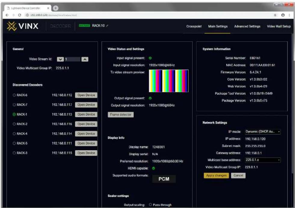
The content of the window is almost the same as in the case of the Encoder. The Video Status Information is filled with details when valid signal is detected and a sink is connected. The addition is the Scaler settings which is also available on the Advanced Settings page.
DEFINITION: Scaling a video signal means changing the image resolution. The new resolution may change the aspect ratio and/or the appearance of the image.
Scaler settings
The outgoing video signal can be set in each Decoders separately.
Output Scaling
- Pass-through: the resolution, the refresh rate, and the type of the outgoing and incoming signals are the same.
- Auto detect from EDID: the resolution of the outgoing video is scaled to meet with the preferred timing coming from the EDID of the connected display device.
- Custom: a wide range of the scaling resolutions are available from 640x480 till 4096x2160.
Output Standard
When the Output scaling is set to Custom, the outgoing signal can be set to DVI or HDMI.
Picture Rotation/Flip
The following options are available:
- No rotation.
- Flip vertically,
- Flip horizontally,
- Rotate by 90 / 180 / 270 degrees.
4.4.4. Network Settings
The factory default IP address of the extender is set to get it from the DHCP server in the network. The drop-down list and the further parameters allow changing the network settings to the desired value.
ATTENTION! When the desired Network parameters are set, press the Apply changes button; the device will reboot.
ATTENTION! Please use the port number 6107 for connecting to the device directly from a third-party application (e.g. a terminal software or other controller application).
text_image
Lightwin Device Controller 192.168.0.126/nnuus/view/index.html VINX DECOOPER RACK-10 Crosspoint Main Settings Advanced Settings Video Wall Setup General Video Stream Id: 1 Video Multicast Group IP: 225.0.1.1 Discovered Encoders RACK-5 192.168.0.112 Open Device RACK-7 192.168.0.117 Open Device RACK-1 192.168.0.113 Open Device RACK-2 192.168.0.116 Open Device RACK-4 192.168.0.114 Open Device RACK-5 192.168.0.111 Open Device RACK-3 192.168.0.115 Open Device Video Status and Settings Input signal present: Input signal resolution: 1920x1080@60Hz Tx video stream preview: Output signal present: Output signal resolution: 1920x1080@60Hz Frame detector Display Info Display name: T248301 Display serial: N/A Preferred resolution: 1920x1080@60.00 Hz HDMI capable: Supported audio formats: PCM Sealer settings Output scaling: Pass-through System Information Serial Number: E80161 MAC Address: 00:11.AA:E8:01:61 Firmware Version: 6.4.24.1 Core Version: v13.0b3 r32 Web Version: v13.0b4 r29 Package Tool Version: v10.0b19 r2449 Package Version: v13.0b5 r75 Network Settings IP mode: Dynamic (DHCP Au... IP address: 192.168.0.120 Subset mask: 235.255.255.0 Gateway address: 192.168.0.1 Multicast base address: 225.0.1.x Video Multicast Group IP: 225.0.1.1 Apply changes CancelThe Main Window of a Decoder (Displayed on a Computer)


- Software Control Options VINX-1x0-HDMI Extenders - User's Manual 21
4.5. Crosspoint Menu
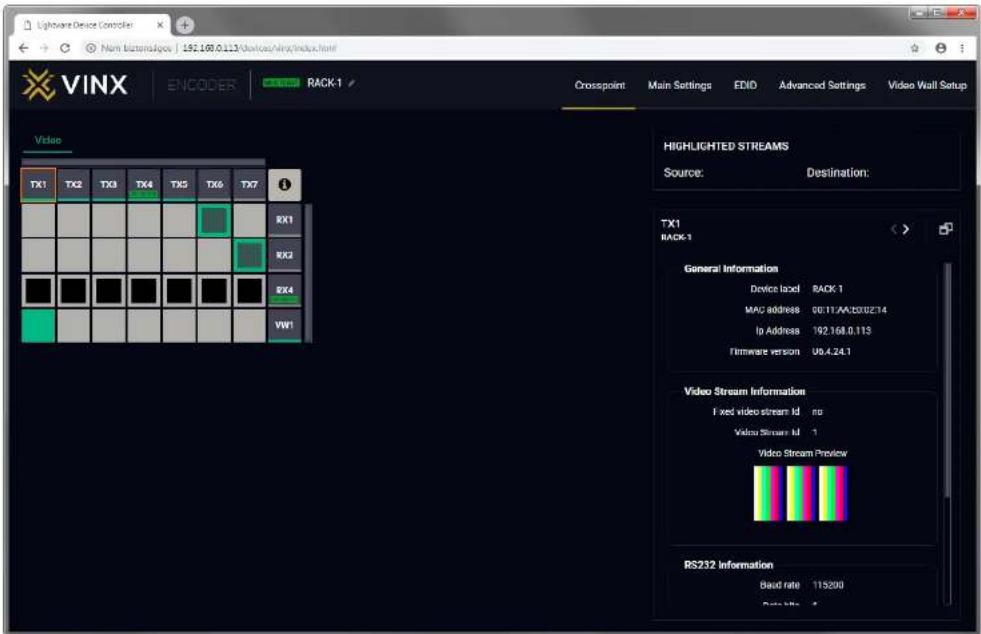
The page allows the user make crosspoint switches between the encoders and the decoder end-points (individual decoders or video walls) in the system. Only at most the first 16 Encoders shall appear in the Crosspoint page. If the subnet contains more encoders, the Crosspoint page shall display an appropriate message indicating why the Crosspoint pane and the Property panel is not displayed. The Crosspoint page can show up to 24 devices (Encoder+Decoder) at most. The TX means the Encoder, the RX means the Decoders, and the defined Video Walls are shown as VW.
ATTENTION! Please note that the Decoders which belong to a Video wall will not be displayed as individual devices.
The applied icons in the Crosspoint mean different states as follows:

Unselected connection
Selected connection with no signal present
Selected connection with signal present
Unselected and disabled connection
Active stream, but no signal present
Stream ID is set by DIP switch
Signal present
Press the Ⓞ button to open the Legend window and display above list.
text_image
Lightwave Device Control Non Buttons/Spoc | 192.109.0.123\devices/VINX/index.html VINX ENCODER RACK-1 Crosspoint Main Settings EDIO Advanced Settings Video Wall Setup HIGHLIGHTED STREAMS Source: Destination: TX1 RACK-1 General Information Device load: RACK-1 MAC address: 00.11.AA:B002:T4 Ip Address: 192.168.0.113 Firmware version: U6.4.24.1 Video Stream Information Fixed video stream Id: no Video Stream Id: 1 Video Stream Preview RS232 Information Band rate: 115200 Data bits: 44.5.1. Frame Detector
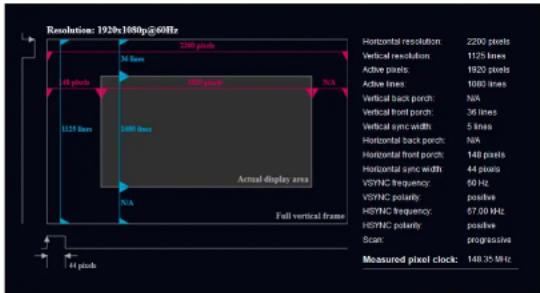
The ports can show detailed information about the signal like blanking intervals and active video resolution. This feature is a good troubleshooter if compatibility problems occur during system installation. Lightware's Frame Detector function works like a signal analyzer and makes possible to determine the exact video format that is present on the port, thus helps to identify many problems. E.g. actual timing parameters may differ from the expected and this may cause some displays to drop the picture.
Frame Detector measures detailed timings on the video signals just like a built-in oscilloscope, but it is much more easy to use. Actual display area shows the active video size (light grey). Dark grey area of the full frame is the blanking interval which can contain the info frames and embedded audio data for HDMI signals. Shown values are measured actually on the signal and not retrieved only from the HDMI info frames.
text_image
Resolution: 1926h/1080hp@60Hz Horizontal resolution: 2200 pixels Vertical resolution: 1125 lines Active pixels: 1920 pixels Active lines: 1080 lines Vertical back porch: N/A Vertical front porch: 36 lines Vertical sync width: 5 lines Horizontal back porch: N/A Horizontal front porch: 148 pixels Horizontal sync width: 44 pixels VSYNC frequency: 60 Hz VSYNC polarity: positive HSYNC frequency: 67.00 kHz HSYNC polarity: positive Scan: progressive Measured pixel clock: 148.35 MHz Actual display area Full vertical frame 1125 lines M lines 148 pixels 1200 pixels N/A N/A 148 pixelsFrame Detector (Opened in a New Tab)
4.6. EDID Menu
DEFINITION: The Extended Display Identification Data (EDID) is the passport of the display devices. It contains information about the capabilities of the display, such as supported resolutions and audio formats, refresh rates, the type and the manufacturer of the display device, etc.
See more information in the EDID Management section.
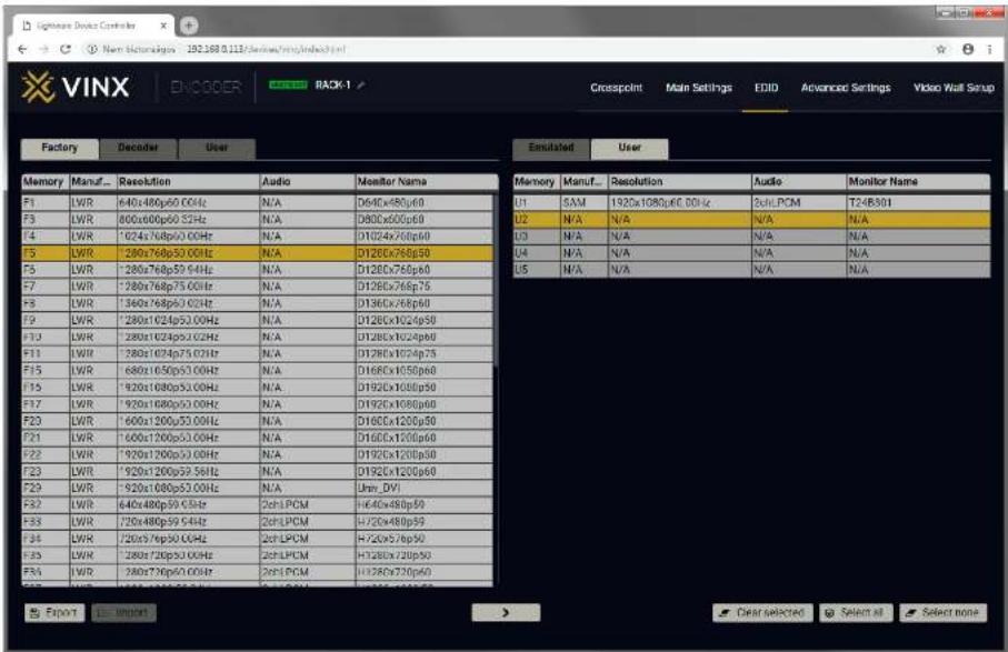
Advanced EDID Management is available in the Encoder. Navigate to the EDID menu. There are two panels: the left contains the Source EDIDs, the right panel contains the Destination places where the EDIDs can be emulated or copied.
4.6.1. The EDID Memory Structure
The EDID memory consists of four parts:
• Factory EDID list shows the pre-programmed EDIDs (F1-F132).
- Decoder EDID list shows the EDIDs of the display devices connected to the assigned Decoders. The Decoders store the last display devices' EDID on the HDMI output, so there is an EDID shown even if there is no display device attached to the output port at that moment.
- User memory locations (U1 - U5) can be used to save custom EDIDs. Any EDID from any of the User/Factory/Decoder EDID lists can be copied to the user memory.
- Emulated EDID shows the currently emulated EDID for the HDMI input port of the Encoder. The source column displays the memory location that the current EDID was routed from.


- Software Control Options VINX-1x0-HDMI Extenders - User's Manual 23
4.6.2. EDID Operations
Changing the Emulated EDID
Step 1. Choose the desired EDID list on the source panel and select an EDID.
Step 2. Select the Emulated tab on the Destination panel.
Step 3. Select the desired port on the right panel.
Step 4. Press the Transfer button to change the emulated EDID.
Learning an EDID
The process is the same as changing the emulated EDID; the only difference is the Destination panel: select the User tab. Thus, one or more EDIDs can be copied into the user memory.
Exporting an EDID
The source EDID can be downloaded as a file (*.EDID) to the computer.
Step 1. Select the desired EDID from the Source panel.
Step 2. Press the Export button and save the file to the computer.
Importing an EDID
Previously saved EDID file (*.EDID) can be uploaded to the user memory:
Step 1. Select the User tab on the Source panel and select a memory slot.
Step 2. Press the Import button below the Source panel.
Step 3. Browse the file in the opening window then press the Open button. The content of the EDID file is imported into the selected User memory.
ATTENTION! The new EDID overwrites the selected memory place.
Deleting EDID(s)
The EDID(s) from the User memory can be deleted as follows:
Step 1. Select the User tab on the Destination panel.
Step 2. Select the desired memory slot(s); one or more can be selected (Select All and Select None buttons can be used).
Step 3. Press the Clear selected button to delete the EDID(s).
text_image
VINX ENOCOER RACK-1 Factory Decoder User Emulated User Memory Manuf... Resolution Audio Monitor Name F1 LWR 640x480p60 00Hz N/A D640x480p60 U1 SAM 1920x1080p60 00Hz 2ndPCM T248301 F3 LWR 800x600p60 52Hz N/A D800x600p60 U2 N/A N/A N/A N/A F4 LWR '024x768p50 00Hz N/A D1024x768p60 U3 N/A N/A N/A N/A F5 LWR '280x768p50 00Hz N/A D1280x768p50 U4 N/A N/A N/A N/A F6 LWR '280x768p59 54Hz N/A D1280x768p60 U5 N/A N/A N/A N/A F7 LWR '280x768p75 00Hz N/A D1280x768p75 F8 LWR '360x768p50 02Hz N/A D1360x768p60 F9 LWR '280x1624p50 00Hz N/A D1280x1624p50 F10 LWR '280x1624p50 02Hz N/A D1280x1624p60 F11 LWR '280x1624p75 07Hz N/A D1280x1624p75 F12 LWR '680x1650p50 00Hz N/A D1680x1650p60 F13 LWR '920x1680p50 00Hz N/A D192Cx1680p50 F14 LWR '920x1680p50 00Hz N/A D192Cx1680p60 F15 LWR '600x1200p50 00Hz N/A D168Cx1200p50 F16 LWR '600x1200p50 00Hz N/A D168Cx1200p60 F17 LWR '920x1200p50 00Hz N/A D192Cx1200p60 F18 LWR '920x1200p50 58HzControl Buttons


The EDID Menu of the Built-in Website
Saving an EDID to a file
Loading an EDID from a file
Executing EDID emulation or copying (Transfer button)

Clearing the selected EDID from the User memory
Selecting all memory places in the right panel
Selecting none of the memory places in the right panel


- Software Control Options VINX-1x0-HDMI Extenders - User's Manual 24
4.7. Advanced Settings
4.7.1. Common Settings (Encoder and Decoder)
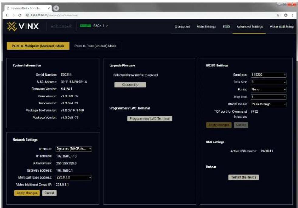
The submenu contains two tabs: Multicast and Unicast. The currently valid mode is highlighted with yellow. Press the desired button to choose the mode and access the settings.
ATTENTION! When the mode is changed the device must be restarted; you will get a notification.
Network Settings
For the details please see the Network Settings section.
Upgrade Firmware
For the details please see the Firmware Upgrade section.
Programmers' LW3 Terminal
See the LW3 Terminal section (next page).
RS-232 Settings
The RS-232 serial data transmission is fully transparent between the Encoder and the connected Decoder devices. All data received on the serial port of the Decoders is transmitted to the serial port of the Encoder and vice versa: the data received on the serial port of the Encoder is transmitted to the serial port of all connected Decoders.
ATTENTION! The data transmission works only if the serial port parameters were set to the same values in all the devices: serial data sender/receiver and the VINX Encoder and Decoder devices. See more information in the RS-232 Interface section.
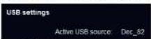
USB Settings (Multicast Mode)
The Encoder displays the name of the currently connected Decoder.
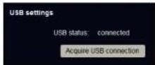
The Decoder displays if the USB connection is established; press the button to acquire the connection if needed.
text_image
Lightwire Device Controller 192.168.0.115/UnicastView/index.html VINX ENCODER RACK-1 Crosspoint Main Settings EDID Advanced Settings Video Wall Setup Point-to-Multipoint (Multicast) Mode Point-to-Point (Unicast) Mode System Information Serial Number: E00214 MAC Address: 08:11:AA:E0:02:14 Firmware Version: 6.4.24.1 Core Version: v1.3.068 r32 Web Version: v1.3/mb4 r29 Package Tool Version: v1.0.0619 r2449 Package Version: v1.3.068 r75 Upgrade Firmware Selected firmware file to upload Choose file Programmers' LW3 Terminal Programmers' LW3 Terminal RS232 Settings Baudrate: 115200 Data bits: 8 Parity: None Stop bits: 1 RS232 mode: Pass through TCP port for Command 6/9/2 Injection: Apply changes Cancel Network Settings IP mode: Dynamic (DHCP, Au... IP address: 192.168.0.113 Submit mask: 255.255.255.0 Gateway address: 192.168.0.1 Multicast base address: 225.0.1.x Video Multicast Group IP: 225.0.1.1 Apply changes Cancel USB settings Active USB source: RACK-11 Reboot Restart the deviceThe Advanced Settings Menu of an Encoder in Multicast Mode


- Software Control Options VINX 1x0-HDMI Extenders - User's Manual 25
4.7.2. Decoder-related Settings
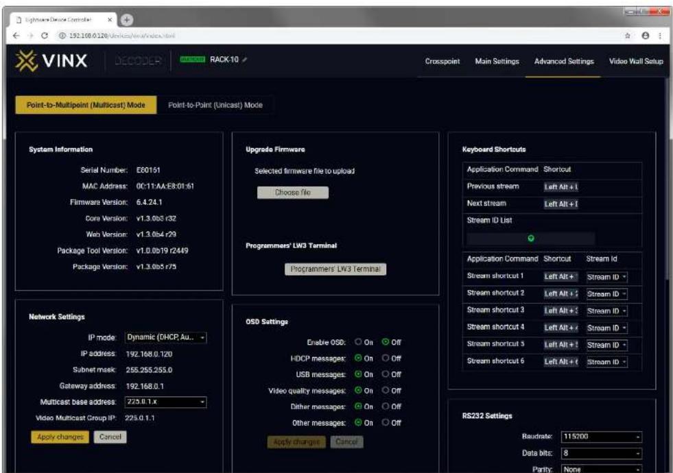
OSD Settings (the On-Screen Display Feature)
Certain system messages can be displayed on the connected screen; the followings are defined:
- Enable OSD: set it to 'ON' state to enable the OSD feature.
• HDCP messages: 'HDCP failed'
• USB messages: 'Requesting USB', 'Starting USB', 'Stopping USB'
• Video quality messages: 'Graphics mode', 'Movie mode'
• Dither messages: reserved
• Other messages: reserved
Press the Apply changes button and restart to save the new settings.
Keyboard Shortcuts
A keyboard connected to the USB 1.1 port of a Decoder can be used to change the assigned Encoder to another one. Thus, the input source of a Decoder can be changed quickly and easily.
INFO: The Video Stream ID of the Decoder is changed when a command is executed.
The shortcut can be set:
• to select a certain stream directly, or
• to select the next/previous stream in the list.
Setting (Changing) a Shortcut
Step 1. Open the web page of the desired Decoder and navigate to the Advanced Settings page.
Step 2. Connect an USB keyboard to that computer directly, or through the desired Decoder and the Encoder (make sure the Encoder is connected to the computer via USB).
Step 3. Place the cursor in the desired Shortcut box.
Step 4. Press the desired key combination; the new setting will be displayed and stored.
Executing a Command (Calling a Shortcut)
Connect the keyboard to an USB 1.1 port (not the USB 2.0!) of the desired Decoder. Press the key(s) three times quickly (within 750 ms).
Stream ID List
You can set a custom list of streams, thus, the Previous/Next stream shortcuts will select the streams in the desired order.
Scaler Settings
The same options as in the Scaler settings section.
text_image
VINC DECODER RACK-10 Crosspoint Main Settings Advanced Settings Video Wall Setup Point-to-Multipoint (Multicast) Mode Point-to-Point (Unicast) Mode System Information Serial Number: E60151 MAC Address: 0C:11-AA:E8:01:61 Firmware Version: 6.4.24.1 Core Version: v1.3.0b5 r32 Web Version: v1.3.0b4 r29 Package Tool Version: v1.0.0b19 r2449 Package Version: v1.3.0b5 r75 Upgrade Firmware Selected firmware file to upload Choose file Programmers' LW3 Terminal Programmers LW3 Terminal Keyboard Shortouts Application Command Shortcut Previous stream Left Alt + I Next stream Left Alt + I Stream ID List Application Command Shortcut Stream Id Stream shortcut 1 Left Alt + Stream ID - Stream shortcut 2 Left Alt + I Stream ID - Stream shortcut 3 Left Alt + I Stream ID - Stream shortcut 4 Left Alt + I Stream ID - Stream shortcut 5 Left Alt + I Stream ID - Stream shortcut 6 Left Alt + I Stream ID - Network Settings IP mode Dynamic (OHCP, Au... IP address 192.168.0.120 Subnet mask 255.255.255.0 Gateway address 192.168.0.1 Multicast base address: 225.0.1.x Video Multicast Group IP: 225.0.1.1 Apply changes Cancel OSD Settings Enable OSD: On Off HDCP messages: On Off USB messages: On Off Video quality messages: On Off Other messages: On Off Other messages: On Off Apply changes Cancel RS232 Settings Baudrate: 115/00 Data bits: 8 Parity: NoneThe Advanced Settings Menu of a Decoder in Multicast Mode


- Software Control Options VINX-1x0-HDMI Extenders - User's Manual 26
4.7.3. LW3 Terminal
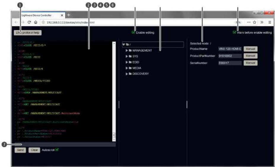
This window is the surface of the Lightware Protocol 3 (LW3) tree with a terminal window. Commands and specific parameters (which are not available on the graphical user interface of the LDC) can be run and set. The introduction of the LW3 protocol and the most important commands can be found in the Programmers' Reference section.
Legend
1 LW3 Protocol Help Displaying the most important information about LW3 protocol commands in a new window.
2 Terminal Window Commands and responses with time and date stamps are listed in this window. Sent command starts with 's' character, received response starts with 'c' character. The content of the window can be emptied by the Clear button. If the Autoscroll option is ticked, the list is scrolled automatically when a new line is added.
3 Edit Mode The default appearance is the read-only mode. If you want to modify the values or parameters, tick the option. You will be prompted to confirm your selection.
4 Protocol Tree LW3 protocol tree; select an item to see its content.
5 Node List The parameters and nodes of the selected item in the protocol tree are shown.
- Manual button: displaying the manual (short description) of the node in a pop-up window.
- Set button: Saving the value/parameter typed in the textbox.
- Call button: Executing the method, e.g. reloading the factory default settings.
6 Warning Mode If this option is enabled, a warning window pops up when you enable the Edit mode.
7 Command Line Type the desired command and execute it by pressing the Send button.
text_image
Lightware Device Controller 192.168.0.113/devices/VinX/index.html LIVs protocol help Enable editing Warn before enable editing SELECTed node / ProductName: VINX-120-HOME Manual ProductPartNumber: 91810002 Manual SerialNumber: E00017 Manual Send Clear AutoscrollThe Terminal Window


- Software Control Options VINX 1x0-HDMI Extenders - User's Manual 27
4.8. Video Wall Setup
ATTENTION! This tab is displayed only when the device is in Multicast mode. Although changing parameters usually takes effect within an acceptable period of time, it might happen that feedback is not received and not visible on the web page for several seconds.
Basic Rules
• One Decoder can be a part of only one video wall.
- The video wall must have a unique name within a system; the length of the name shall not exceed 24 characters.
- The video wall parameters are stored in the LW3 protocol tree of the Decoders but you can also create/access it in the Encoder.
4.8.1. Creating a Video Wall
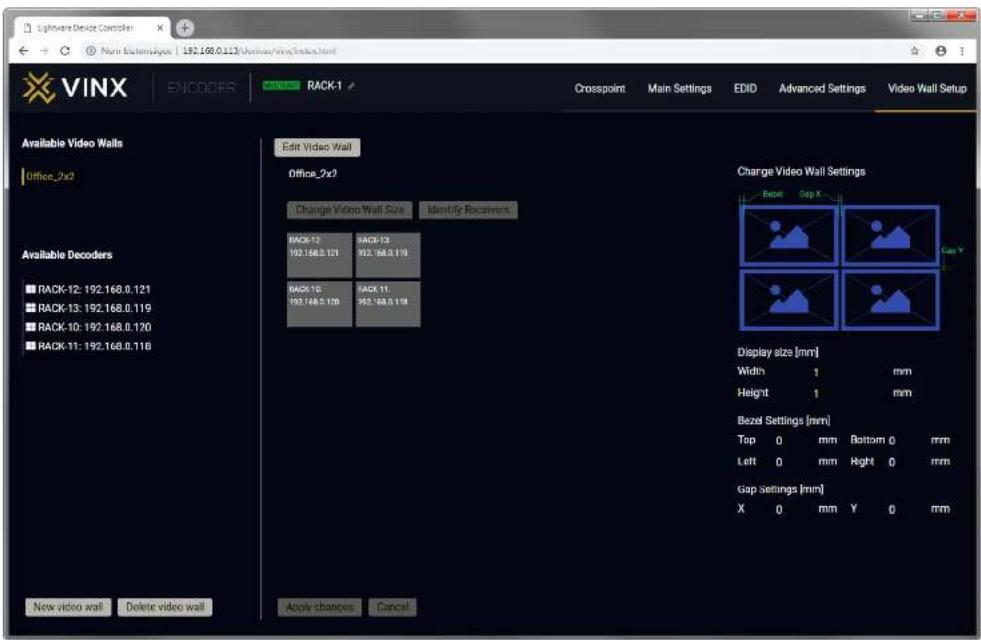
Step 1. Navigate to the Video Wall Setup page. Step 2. Press the New video wall button. Enter the desired name of the wall (press the pencil icon ↗ to change) and press the Enter or click on the pencil icon.
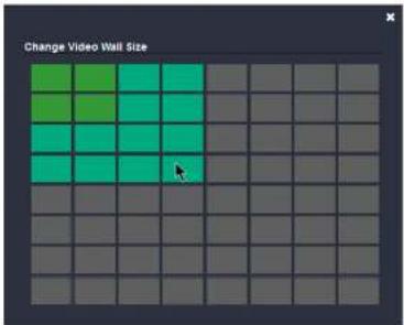
Step 3. Press the Change Video Wall Size button to set the exact size of the wall. A new window will pop up, click on the desired size.
text_image
Change Video Wall SizeStep 4. Drag and drop the Decoders to the desired place in the wall. Step 5. Press the Apply changes button to save the settings.
ATTENTION! A New video wall is stored only when at least one Decoder is linked to the wall.
text_image
VINC ENCODER RACK-1 Crosspoint Main Settings EDID Advanced Settings Video Wall Setup Available Video Walls Office_2x2 Edit Video Wall Office_2x2? Change Video Wall Size Identify Recovers Charge Video Wall Settings Bezel Gap X Gay Y Available Decoders BACK-12 192.168.0.121 BACK-13 192.168.0.119 BACK-14 192.168.0.120 BACK-15 192.168.0.118 Back 10 192.168.0.120 Back 11 192.168.0.118 Display size [mm] Width 1 mm Height 1 mm Bezel Settings [mm] Top 0 mm Bottom 0 mm Left 0 mm Right 0 mm Gap settings [mm] X 0 mm Y 0 mm New video wall Delete video wall Apply changes CancelThe Video Wall Setup Page
4.8.2. Identify the Decoders
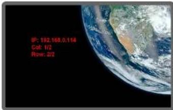
The Decoders of a video wall can be identified by pressing the Identify Receivers button. In this case, the IP address and the position in the Video wall are displayed on the connected screens.
text_image
IP: 192.168.0.114 Cat: 1/2 Row: 2/24.8.3. Gap and Bezel Settings
ATTENTION! Always press the Apply changes button if you want to save the changes of the below mentioned parameters.
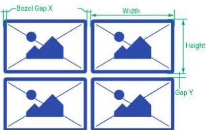
DEFINITION: Hereby defined Gap means the physical distance between the edges of the display devices – see the attached figure. DEFINITION: The Bezel means the thickness of the Display device's frame – see the attached figure.
In certain cases, the dimensions of the sinks and the arrangement of the video wall requires special parameters to set. The Gap and Bezel parameters allow setting the non-visible areas (between the display devices) of the image:


No Gap (left) and Manually Set Gap (right)
- No Gap: The left figure shows that no gap is defined. In this case, the whole image is shown on the screens but the image looks a bit distorted.
- Defined Gap: The right figure shows that gap is defined, therefore, some part of the image is not visible, but the appearance of the overall image is more realistic.
Set the bezel and gap parameters which suit the best for the current image content.
The following parameters can be set:
- Display Size (width and height): the physical size (dimensions) of the screen (screen size + bezel).
- Bezel Settings (top, bottom, left, right): the physical size (thickness) of the bezel.
- Gap Settings (horizontal, vertical): the distance of the displays (see the following section).
INFO: If the Bezel and Gap values are set to zero the Display size values (dimensions) do not matter.
text_image
Bezel Gap X Width Height Gap Y4.8.4. Modifying a Video Wall
The Name of the Video Wall
Step 1. Press the Edit Video Wall button.
Step 2. Change the name of the video wall and press the Apply changes button.
Changing the Layout of the Decoders
Step 1. Press the Edit Video Wall button.
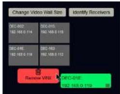
Step 1. Drag and drop a Decoder to the below indicated red colored (hidden) place; the device will be removed from the wall.
text_image
Change Video Wall Size Identify Receivers DEC-002 192 168.0 114 DEC-015 192 168.0 116 DEC-01E 192 168.0 118 DEC-02E 192 168.0 112 Remove VDSL DEC-01E 192 168.0 119Step 2. Another Decoder can be dragged and dropped to the empty place.
Step 3. Press the Apply changes button to save the settings.
ATTENTION! If you reduce the size of an existing video wall, the Decoders which would be outside of the new area show the original picture.
Changing the Gap and Bezel Settings
Step 1. Press the Edit Video Wall button.
Step 2. Set the desired gap and bezel values and press the Apply changes button the save the settings.
4.8.5. Deleting a Video Wall
Step 1. Select the video wall from the list.
Step 2. Click on the Delete video wall button and confirm in the pop-up window. The original image will be displayed on all connected Decoders.
5
Programmers' Reference
The device can be controlled through Lightware 3 (LW3) protocol commands to ensure the compatibility with other Lightware products. The supported LW3 commands are described in this chapter.
▶ OVERVIEW
▶ PROTOCOL RULES
▶ SYSTEM COMMANDS
▶ NETWORK CONFIGURATION
▶ ENCODER-RELATED COMMANDS
▶ DECODER-RELATED COMMANDS
▶ SERIAL PORT SETTINGS
ARRANGING THE EXTENDERS TO GROUPS
VIDEO WALL SETTINGS
▶ SETTING UP A VIDEO WALL (EXAMPLE)
▶ CROSSPOINT SWITCHING EXAMPLES
▶ EDID MANAGEMENT (ENCODER)
LW3 COMMANDS - QUICK SUMMARY
5.1. Overview
The Lightware Protocol #3 (LW3) is implemented in almost all new Lightware devices (matrix switchers, signal extenders and distribution amplifiers) since 2012. The protocol is ASCII-based and all commands are terminated with a carriage return (Cr, 'r') and line feed (Lf, '\n') pair. It is organized as a tree structure that provides outstanding flexibility and user-friendly handling with 'nodes', 'properties' and 'methods'. The Advanced View of the built-in web page is the perfect tool for browsing and learning how the LW3 protocol can be used in practice.
5.2. Protocol Rules
5.2.1. The LW3 Tree Structure
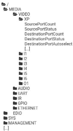
text_image
/ MEDIA VIDEO XP SourcePortCount SourcePortStatus DestinationPortCount DestinationPortStatus DestinationPortAutoselect [...] I1 I2 I3 I4 I5 I6 I1 AUDIO UART IR GPIO ETHERNET EDID SYS MANAGEMENT [...]5.2.2. The LW3 Command Structure
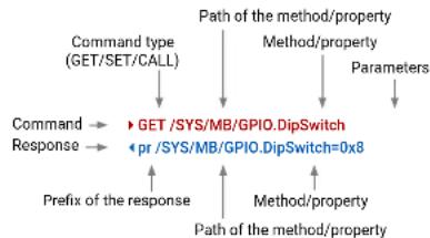
flowchart
graph TD
    A["Command type (GET/SET/CALL)"] --> B["Path of the method/property"]
    B --> C["Parameters"]
    D["Command Response"] --> E["GET /SYS/MB/GPIO.DipSwitch"]
    D --> F["pr /SYS/MB/GPIO.DipSwitch=0x8"]
    G["Prefix of the response"] --> E
    H["Method/property"] --> F
    I["Path of the method/property"] --> E
5.2.3. Legend for the Control Commands
Command and Response - Example
▶ GET-/SYS/MB/GPIO.DipSwitch
pr*/SYS/MB/GPIO.DipSwitch=
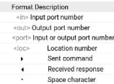
text_image
Format DescriptionFurther not listed
5.2.4. General Rules
• All names and parameters are case-sensitive.
• The nodes are separated by a slash (/") character.
- The node name can contain the elements of the English alphabet and numbers.
• Use the TCP port no. 6107 when using LW3 protocol over Ethernet.
- When a command is issued by the device, the received response cannot be processed by the CPU.
- The path of a node has to contain all parent nodes from the root node.
5.2.5. Command Types
GET command
The GET command can be used to get the child nodes, properties and methods of a specific node. It can also be used to get the value of a property. Use the dot character (.) when addressing a property:
▶ GET/.SerialNumber
pr/.SerialNumber=87654321
GETALL command
The GETALL command can be used to get all child nodes, properties and methods of a node with one command.
▶ GETALL/MEDIA/UART
n-/MEDIA/VIDEO/I1
n-/MEDIA/VIDEO/01
n-/MEDIA/VIDEO/QUALITY
The SET command can be used to modify the value of a property. Use the dot character () when addressing the property:
SET /MEDIA/VIDEO/QUALITY.QualityMode=0
pw /MEDIA/VIDEO/QUALITY.QualityMode=0
CALL command
A method can be invoked by the CALL command. Use the colon character (:) when addressing the method:
CALL /MEDIA/VIDEO/QUALITY:applySettings(true)
• mO /MEDIA/VIDEO/QUALITY:applySettings
5.2.6. Prefix Summary
DEFINITION: The prefix is a 2-character long code that describes the type of the response.
The following prefixes are defined in the LW3 protocol:
Prefix Description
n-a node
nE an error for a node
nm a manual of a node
ns a child node of a node
pr a read-only property
pw read-write properly
pE an error for the property
pm a manual for the property
m-a method
m0 a response after a success method execution
mF a response after a failed method execution
mE an error for a method
mm a manual for a method
5.2.7. Error Messages
There are several error messages defined in the LW3 protocol, all of them have a unique error number.
SET/MEDIA/UART/P1.Baudrate=9
pE /MEDIA/UART/P1.Baudrate %E004:Invalid value
5.2.8. Escaping
DEFINITION: An escape sequence is a sequence of characters that does not represent itself when used inside a character or string literal, but is translated into another character or a sequence of characters.
Property values and method parameters can contain characters which are used as control characters in the protocol. They must be escaped. The escape character is the backslash ('') and escaping means injecting a backslash before the character that should be escaped (like in C language).
Control characters are the followings: # % ()
The original message:
CALL /MEDIA/UART/P1: sendMessage(Set(01))
The escaped message:
CALL /MEDIA/UART/P1: sendMessage(Set\01))
5.2.9. Subscription
DEFINITION: Subscribe to a node means that the user will get a notification if any of the properties of the node is changed.
A user can subscribe to any node. These notifications are asynchronous messages and they are useful to keep the client application up to date, without receiving any unwanted information. When the user does not want to be informed about the changes anymore, he can simply unsubscribe from the node.
ATTENTION! The subscriptions are handled separately for connections. Hence, if the connection is terminated all registered subscriptions are deleted. After closing a connection the subscribe command has to be sent in order to get the notifications of the changes on that connection.
Subscribe to a Node
OPEN/MEDIA/VIDEO
- o-/MEDIA/VIDEO
Get the Active Subscriptions
OPEN
o-/MEDIA/VIDEO
o-/EDID
- o-/DISCOVERY
Subscribe to Multiple Nodes
OPEN/MEDIA/VIDEO/*
- o-/MEDIA/V
Unsubscribe from a Node
CLOSE/MEDIA/VIDEO
c-/MEDIA/VIDEO
Unsubscribe from Multiple Nodes
CLOSE/MEDIA/VIDEO/*
c-/MEDIA/VIDEO/*


- Programmers' Reference VINX-1x0-HDMI Extenders - User's Manual 31
5.2.10. Signature
DEFINITION: The signature is a four-digit-long hexadecimal value that can be optionally placed before every command to keep a command and the corresponding responses together as a group.
Each line is terminated with a carriage return (Cr, 'r') and line feed (Lf, 'n') characters. In several cases the number of the lines in the response cannot be determined in advance, e.g. the client is intended waiting for the whole response and also wants to be sure, that the received lines belong together and to the same command. In these cases, a special feature the 'signature' can be used. In these cases, the response to that particular command will also be preceded by the signature, and the corresponding lines will be between brackets:
1700#GET/EDID.
{1700
pr /EDID.EdidStatus=F89:E1;D1:E2;D1:E3;D1:E4;F89:E5
m-/EDID:copy
m-/EDID:delete
m-/EDID:reset
m-/EDID:switch
m-/EDID:switchAll
< }
INFO: The lines of the signature are also Cr and Lf terminated.
5.2.11. Notifications about the Changes of the Properties
When the value of a property is changed and the user is subscribed to the node, which the property belongs to, an asynchronous notification is generated. This is notification is called as the 'change message'. The format of such a message is very similar to the response for the GET command:
CHG/EDID.EdidStatus=F48:E1
A Short Example of How to Use the Subscription
There are two independent users controlling the device through two independent connections (Connection #1 and Connection #2). The events in the rows occur after each other.
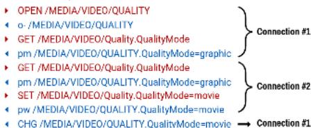
text_image
OPEN /MEDIA/VIDEO/QUALITY o-/MEDIA/VIDEO/QUALITY GET /MEDIA/VIDEO/Quality.QualityMode pm /MEDIA/VIDEO/QUALITY.QualityMode=graphic GET /MEDIA/VIDEO/Quality.QualityMode pm /MEDIA/VIDEO/QUALITY.QualityMode=graphic SET /MEDIA/VIDEO/Quality.QualityMode=movie pw /MEDIA/VIDEO/QUALITY.QualityMode=movie CHG /MEDIA/VIDEO/QUALITY.QualityMode=movie Connection #1 Connection #2 Connection #1Explanation: The first user (Connection #1) set a subscription to a node. Later the other user (Connection #2) made a change, and thanks for the subscription, the first user got a notification about the change.
5.3. System Commands
5.3.1. Querying the Product Name
Command and Response
▶ GET•/.ProductName
pr•/.ProductName=
Parameters
The
Example
▶ GET/.ProductName
pr/.ProductName=VINX-120-HDMI-ENC
5.3.2. Setting the Device Label
Unique name can be set which will be visible when the given device is listed in the built-in web page of other
VINX devices. Furthermore, the name is listed when browsing the client list of a DHCP server.
ATTENTION! This property is a writable parameter and not the same as the ProductName.
Command and Response
SET·/SYS/MB.DeviceLabel=
pw-/SYS/MB.DeviceLabel=
Parameters
The
Example
SET /SYS/MB.DeviceLabel=Enc_80
pw /SYS/MB.DeviceLabel=Enc_80
5.3.3. Querying the Serial Number
Command and Response
▶ GET•/.SerialNumber
- pr*/SerialNumber=
Example
▶ GET/.SerialNumber
pr/.SerialNumber=87654321


- Programmers' Reference VINX-1x0-HDMI Extenders - User's Manual 32
5.3.4. Querying the Firmware Version
Command and Response
▶ GET-/SYS/MB.FirmwareVersion
pr*/SYS/MB.FirmwareVersion=
Example
▶ GET /SYS/MB.FirmwareVersion
pr /SYS/MB.FirmwareVersion=6.4.17.3
5.3.5. Querying the Core Version
Command and Response
▶ GET-/SYS/MB.CoreVersion
pr*/SYS/MB.CoreVersion=
Example
▶ GET /SYS/MB.CoreVersion
pr /SYS/MB.CoreVersion=v1.0.0b4 r7
5.3.6. Resetting the Device
The extender can be restarted; the current connections (RS-232, USB, etc...) will be terminated.
Command and Response
CALL·/SYS:reset()
mO+/SYS:Reset
Example
CALL /SYS:reset()
m0 /SYS:reset
5.3.7. Restoring the Factory Default Settings
Command and Response
CALL-/SYS:factoryDefaults()
- mO+/SYS:factoryDefaults=
Example
CALL /SYS:factoryDefaults()
mO /SYS:factoryDefaults=
The device is restarted, the current connections are terminated, the default settings are restored. See the complete list in the Factory Default Settings section.
5.4. Network Configuration
ATTENTION! When you change a network property the new value is stored but the applySettings method must be called always to apply the new settings. When two or more serial parameters are changed the applySettings method is enough to call once as a final step; it results the extender to reboot.
5.4.1. Querying the IP Address
Command and Response
▶ GET-/MANAGEMENT/NETWORK.IpAddress
pr-/MANAGEMENT/NETWORK.IpAddress=
Example
▶ GET/MANAGEMENT/NETWORK.IpAddress
pr /MANAGEMENT/NETWORK.IpAddress=192.168.0.100
5.4.2. Querying the DHCP State
Command and Response
▶ GET+/MANAGEMENT/NETWORK.DhcpEnabled
pw-/MANAGEMENT/NETWORK.DhcpEnabled=
Parameters
If the
Example
▶ GET /MANAGEMENT/NETWORK.DhcpEnabled
pw /MANAGEMENT/NETWORK.DhcpEnabled=true
Explanation
The IP address assignment is dynamic, the device gets the IP address from the DHCP server.


- Programmers' Reference VINX-1x0-HDMI Extenders - User's Manual 33
5.4.3. Setting the DHCP State
Command and Response
▶ SET·/MANAGEMENT/NETWORK.DhcpEnabled=
pw*/MANAGEMENT/NETWORK.DhcpEnabled=
Parameters
See the previous section.
Example
SET /MANAGEMENT/NETWORK.DhcpEnabled=0
pw /MANAGEMENT/NETWORK.DhcpEnabled=false
CALL /MANAGEMENT/NETWORK:applySettings(1)
- mO /MANAGEMENT/NETWORK:applySettings
INFO: The applySettings method will save and apply the new value and results the extender to reboot.
Explanation
The IP address assignment is set to static, thus, you have to set it manually.
5.4.4. Setting a Static IP Address
When the DhcpEnabled property is false you can set a static IP address (dot-decimal notation).
Command and Response
▶ SET·/MANAGEMENT/NETWORK.StaticIpAddress=
pw*/MANAGEMENT/NETWORK.StaticIpAddress=
CALL /MANAGEMENT/NETWORK:applySettings(1)
mO/MANAGEMENT/NETWORK:applySettings
INFO: The applySettings method will save and apply the new value and results the extender to reboot.
Example
SET /MANAGEMENT/NETWORK.StaticIpAddress=192.168.0.85
pw /MANAGEMENT/NETWORK.StaticIpAddress=192.168.0.85
5.4.5. Querying the Subnet Mask
Command and Response
▶ GET+/MANAGEMENT/NETWORK.NetworkMask
pr-/MANAGEMENT/NETWORK.NetworkMask=
Example
▶ GET/MANAGEMENT/NETWORK.NetworkMask
pr /MANAGEMENT/NETWORK.NetworkMask=255.255.255.0
5.4.6. Setting a Static Subnet Mask
When the DhcpEnabled property is false you can set a static subnet mask (dot-decimal notation).
Command and Response
SET·/MANAGEMENT/NETWORK.StaticNetworkMask=
pw-/MANAGEMENT/NETWORK.StaticNetworkMask=
Example
SET /MANAGEMENT/NETWORK.StaticNetworkMask=255.255.255.0
pw /MANAGEMENT/NETWORK.StaticNetworkMask=255.255.255.0
CALL /MANAGEMENT/NETWORK:applySettings(1)
mO /MANAGEMENT/NETWORK:applySettings
INFO: The applySettings method will save and apply the new value and results the extender to reboot.
5.4.7. Querying the Gateway Address
Command and Response
▶ GET·/MANAGEMENT/NETWORK.GatewayAddress
pr-/MANAGEMENT/NETWORK.GatewayAddress=
Example
▶ GET /MANAGEMENT/NETWORK.GatewayAddress
pr /MANAGEMENT/NETWORK.GatewayAddress=192.168.0.1
5.4.8. Setting a Static Gateway Address
When the DhcpEnabled property is false you can set a static subnet mask (dot-decimal notation).
Command and Response
SET·/MANAGEMENT/NETWORK.StaticGatewayAddress=
pw*/MANAGEMENT/NETWORK.StaticGatewayAddress=
CALL /MANAGEMENT/NETWORK:applySettings(1)
mO /MANAGEMENT/NETWORK:applySettings
INFO: The applySettings method will save and apply the new value and results the extender to reboot.
Example
SET /MANAGEMENT/NETWORK.StaticGatewayAddress=192.168.0.5
pw /MANAGEMENT/NETWORK.StaticGatewayAddress=192.168.0.5


- Programmers' Reference VINX-1x0-HDMI Extenders - User's Manual 34
5.5. Encoder-related Commands
5.5.1. Querying the Input Video Signal Presence
The HDMI input port can be queried if video signal is present.
Command and Response
▶ GET-/MEDIA/VIDEO/
pr*/MEDIA/VIDEO/
Parameters
If the
Example
▶ GET /MEDIA/VIDEO/I1.SignalPresent
pr /MEDIA/VIDEO/I1.SignalPresent=1
5.5.2. Querying the Resolution of the Input Video Signal
The resolution and the refresh rate of the incoming video signal can be queried.
Command and Response
▶ GET+/MEDIA/VIDEO/
pr-/MEDIA/VIDEO/
Example
▶ GET /MEDIA/VIDEO/I1.Resolution
pr /MEDIA/VIDEO/I1.Resolution=1280x720@60Hz
5.5.3. Querying the Video Quality Mode
When the network bandwidth is not enough to transmit the video signal the following modes are available in the Encoder:
- Movie mode (Lower image quality @ Less bandwidth): The image quality is adjusted to the available bandwidth. If the bandwidth is decreased the image quality will be lower, but the video streaming is continuous.
- Graphics mode (Best image quality @ High bandwidth): The image quality is kept at a high level. If the bandwidth is decreased the image quality does not change, but frame drop may appear.
Command and Response
▶ GET-/MEDIA/VIDEO/QUALITY.QualityMode
pw-/MEDIA/VIDEO/QUALITY.QualityMode=
Parameters
The value of the
Example
▶ GET /MEDIA/VIDEO/QUALITY.QualityMode
pw /MEDIA/VIDEO/QUALITY.QualityMode=movie
5.5.4. Setting the Video Quality Mode
The video quality mode can be set in the Encoder (see the previous section for details about the modes):
Command and Response
SET-/MEDIA/VIDEO/QUALITY.QualityMode=
pw*/MEDIA/VIDEO/QUALITY.QualityMode=
Parameters
See the previous section.
Example
SET /MEDIA/VIDEO/QUALITY.QualityMode=graphic
pw /MEDIA/VIDEO/QUALITY.QualityMode=graphic


- Programmers' Reference VINX-1x0-HDMI Extenders - User's Manual 35
5.5.5. Querying the HDCP State
The current state of the HDCP encryption can be queried at the input port; see the HDCP Management section.
Command and Response
▶ GET+/MEDIA/VIDEO/
pr-/MEDIA/VIDEO/
Parameters
If the
Example
▶ GET /MEDIA/VIDEO/I1.HdcpState
pr /MEDIA/VIDEO/I1.HdcpState=1
5.5.6. Setting the HDCP State
HDCP capability can be enabled/disabled on the input port of the Encoder, thus, non-encrypted content can be seen on a non-HDCP compliant display if the content allows it; see the HDCP Management section.
Command and Response
SET·/MEDIA/VIDEO/
pw-/MEDIA/VIDEO/
ATTENTION! When you change this properly the applySettings method must be called always to store the new setting. If the HDCP State is changed the device is restarted automatically.
Parameters
See the previous section.
Example
SET /MEDIA/VIDEO/I1.HdcpEnable=0
pw /MEDIA/VIDEO/I1.HdcpEnable=false
CALL /MEDIA/VIDEO/I1:applySettings()
mO /MEDIA/VIDEO/I1:applySettings
ATTENTION! The EDID information cannot be read by the source attached to the HDMI input of an Encoder if HDCP is disabled on the input. That may stop the video transmission in the case of certain source devices.
5.6. Decoder-related Commands
5.6.1. Querying the Resolution of the Output Video Signal
The resolution and the refresh rate of the outgoing video signal can be queried.
Command and Response
▶ GET-/MEDIA/VIDEO/
pr*/MEDIA/VIDEO/
Example
▶ GET /MEDIA/VIDEO/O1.Resolution
pr /MEDIA/VIDEO/01.Resolution=1600x1200@60Hz
5.6.2. Querying the Scaling Mode of the Output Video Signal
Command and Response
▶ GET·/MEDIA/VIDEO/
pw*/MEDIA/VIDEO/
Parameters
Identifier Parameter description Parameter values
OFF: Scaling is disabled, the resolution is not changed. EDID: the resolution is set to meet with the preferred timing of the sink device. MANUAL: Scaling is set manually.
MANUAL: Scaling is set manually.
Example
▶ GET /MEDIA/VIDEO/01/SCALERScalingMode
pw /MEDIA/VIDEO/01/SCALER.ScalingMode=MANUAL
See more information about the scaling modes in the Video Status and Settings (Decoder) section.
5.6.3. Setting the Scaling Mode of the Output Video Signal
Command and Response
SET·/MEDIA/VIDEO/
pw-/MEDIA/VIDEO/
Parameters
See the previous section.
Example
▶ SET /MEDIA/VIDEO/01/SCALER.ScalingMode=OFF
pw /MEDIA/VIDEO/01/SCALER.ScalingMode=OFF
See more information about the scaling modes in the Video Status and Settings (Decoder) section.


- Programmers' Reference VINX-1x0-HDMI Extenders - User's Manual 36
5.6.4. Setting the Resolution of the Output Video Signal
The resolution and the refresh rate of the outgoing video signal can be set.
Command and Response
▶ SET*/MEDIA/VIDEO/
pw*/MEDIA/VIDEO/
Parameters
The
Example
SET /MEDIA/VIDEO/01/SCALER.OutputResolution=81004088
pw /MEDIA/VIDEO/01/SCALER.OutputResolution=81004088
Explanation
The new value of the parameter is 81004088 which means the resolution of the output signal is set to 1280x720@60Hz.
ATTENTION! Set the ScalingMode property to MANUAL after changing the Resolution property manually to apply the new settings.
5.6.5. Querying the Signal Type of the Output Video Signal
Command and Response
- GET-/MEDIA/VIDEO/
pw-/MEDIA/VIDEO/
Parameters
The
Example
▶ GET /MEDIA/VIDEO/01/SCALER.SignalType
pw /MEDIA/VIDEO/O1/SCALER.SignalType=HDMI
5.6.6. Setting the Signal Type of the Output Video Signal
Command and Response
▶ SET·/MEDIA/VIDEO/
pw*/MEDIA/VIDEO/
Parameters
See the previous section.
Example
SET /MEDIA/VIDEO/01/SCALER.SignalType=HDMI
pw /MEDIA/VIDEO/01/SCALER.SignalType=HDMI
INFO: The property takes effect only when the ScalingMode property is set to MANUAL setting.
5.6.7. Querying the State of the USB Connection
When the extenders are in Multicast mode the USB transmission has to be determined by selecting the active Decoder. To query the current state of a given Decoder use the following command:
Command and Response
▶ GET-/MEDIA/KM.Controlling
pr+/MEDIA/KM. Controlling=
Parameters
If the
Example
▶ GET /MEDIA/KM. Controlling
pr /MEDIA/KM. Controlling=false
See more information about the USB features in the USB Interface section.
5.6.8. Establishing the USB Connection
When the extenders are in Multicast mode the USB transmission has to be determined by selecting the active Decoder. To establish the connection between the Decoder and the Encoder use the following command:
Command and Response
CALL·/MEDIA/KM:acquireControl(true)
- mO-/MEDIA/KM:acquireControl
Example
CALL /MEDIA/KM:acquireControl(1)
mO /MEDIA/KM:acquireControl
ATTENTION! Establishing the connection to a Decoder will disconnect the USB transmission of the previously connected Decoder.


- Programmers' Reference VINX-1x0-HDMI Extenders - User's Manual 37
5.7. Serial Port Settings
ATTENTION! The new port settings are stored but applied only if the applySettings method is called which will reboot the device. When two or more serial parameters are changed the applySettings method is enough to call once as a final step: it results the extender to reboot.
INFO: Below listed commands can be used to set the RS-232 port parameters. To query the current value of a parameter use the GET command, e.g.: GET/MEDIA/UART/P1.BaudRate.
5.7.1. Setting the Port Availability
ATTENTION! The port must be enabled for the RS-232 data transmission; use this command.
Command and Response
▶ SET·/MEDIA/UART/
pw-/MEDIA/UART/
Parameters
If the
Example
▶ SET /MEDIA/UART/P1.Enabled=true
pw /MEDIA/UART/P1.Enabled=true
CALL /MEDIA/UART/P1:applySettings(1)
mO /MEDIA/UART/P1:applySettings
INFO: The applySettings method will save and apply the new value and makes the extender reboot.
5.7.2. Setting the Baud Rate of the Port
Command and Response
▶ SET·/MEDIA/UART/
pw*/MEDIA/UART/
Parameters
The
Example
SET /MEDIA/UART/P1.Baudrate=57600
pw /MEDIA/UART/P1.Baudrate=57600
CALL /MEDIA/UART/P1:applySettings(1)
mO /MEDIA/UART/P1:applySettings
INFO: The applySettings method will save and apply the new value and makes the extender reboot.
5.7.3. Setting the RS-232 Port Mode
The RS-232 port can be set to Pass-through or Command Injection mode. The introduction of these modes can be found in the RS-232 Interface section.
Command and Response
▶ SET·/MEDIA/UART/
pw-/MEDIA/UART/
Parameters
If the
Example
▶ SET /MEDIA/UART/P1.Guest=false
pw /MEDIA/UART/P1.Guest=false
CALL /MEDIA/UART/P1:applySettings(1)
mO /MEDIA/UART/P1:applySettings
INFO: The applySettings method will save and apply the new value and makes the extender reboot.
5.7.4. Setting the Data Bits
Command and Response
▶ SET·/MEDIA/UART/
pw:/MEDIA/UART/
Parameters
The
Example
▶ SET /MEDIA/UART/P1.DataBits=8
pw /MEDIA/UART/P1.DataBits=8
CALL /MEDIA/UART/P1:applySettings(1)
m0 /MEDIA/UART/P1:applySettings
INFO: The applySettings method will save and apply the new value and makes the extender reboot.


- Programmers' Reference VINX-1x0-HDMI Extenders - User's Manual 38
5.7.5. Setting the Stop Bits
Command and Response
▶ SET·/MEDIA/UART/
pw*/MEDIA/UART/
Parameters
The
Example
▶ SET /MEDIA/UART/P1.StopBits=1
pw /MEDIA/UART/P1.StopBits=1
CALL /MEDIA/UART/P1:applySettings(1)
mO /MEDIA/UART/P1:applySettings
INFO: The applySettings method will save and apply the new value and makes the extender reboot.
5.7.6. Setting the Parity
Command and Response
- SET-/MEDIA/UART/
.Parity=
pw*/MEDIA/UART/.Parity=
Parameters
Identifier Parameter description Parameter values
a: odd
e: even
Example
▶ SET /MEDIA/UART/P1.Parity=n
pw /MEDIA/UART/P1.Parity=n
CALL /MEDIA/UART/P1:applySettings(1)
mO /MEDIA/UART/P1:applySettings
INFO: The applySettings method will save and apply the new value and makes the extender reboot.
5.8. Arranging the Extenders to Groups
5.8.1. Querying the Working Mode (Unicast/Multicast)
Command and Response
▶ GET-/MANAGEMENT/MULTICAST.MulticastMode
pw*/MANAGEMENT/MULTICAST.MulticastMode=
Parameters
If the
Example
▶ GET/MANAGEMENT/MULTICAST.MulticastMode
pw /MANAGEMENT/MULTICAST.MulticastMode=false
5.8.2. Setting the Working Mode (Unicast/Multicast)
Command and Response
SET·/MANAGEMENT/MULTICAST.MulticastMode=
pw-/MANAGEMENT/MULTICAST.MulticastMode=
Parameters
See the previous section.
Example
SET/MANAGEMENT/MULTICAST.MulticastMode=1
pw /MANAGEMENT/MULTICAST.MulticastMode=true
CALL /MANAGEMENT/MULTICAST:applySettings(1)
ATTENTION! When you change the working mode the applySettings method must be called always to store the new settings. After that, the device is restarted automatically; response is not sent.


- Programmers' Reference VINX-1x0-HDMI Extenders - User's Manual 39
5.8.3. Querying the Video Stream ID Setting Method
The Video stream ID can be set by the front panel DIP switch or by software.
Command and Response
▶ GET+/SYS/MB/PHY.ChannelIdSetBySoftware
pr-/SYS/MB/PHY.ChannelIdSetBySoftware=
Parameters
If the
Example
▶ GET /SYS/MB/PHY.ChannelIdSetBySoftware
pr /SYS/MB/PHY.ChannelIdSetBySoftware=false
Explanation
The current Video Stream ID is HW setting, the front panel DIP switch is valid. The ID can be changed only by the DIP switch.
ATTENTION! The state of the DIP switch can be ignored, see the DIP Switch Enable section.
5.8.4. Querying the DIP Switch Value
The current value of the DIP switch can be queried as follows:
Command and Response
▶ GET-/SYS/MB/GPIO.DipSwitch
pr*/SYS/MB/GPIO.DipSwitch=
Parameters
The states/values of the
Example
▶ GET /SYS/MB/GPIO.DipSwitch
pr /SYS/MB/GPIO.DipSwitch=0x8
Explanation
The current value is 0x8: the switch is in '1000' state, the Video Stream ID is '8'.
5.8.5. Querying the Video Stream ID
The response of the below command contains the current Video Stream ID, but contains no information about the setting method (HW setting/SW setting).
Command and Response
▶ GET-/SYS/MB/PHY.VideoChannelId
pw-/SYS/MB/PHY.VideoChannelId=
Parameter
The value of the
Example
▶ GET /SYS/MB/PHY.VideoChannelId
pw /SYS/MB/PHY.VideoChannelId=10
5.8.6. DIP Switch Enable
The front panel DIP switch can be ignored by the below command. The command can be used to avoid an accidental Video stream ID change caused by a front panel switching.
Command and Response
SET-/SYS/MB/GPIO.DipSwitchEnable=
pw*/SYS/MB/GPIO.DipSwitchEnable=
Parameters
If the
Example
SET /SYS/MB/GPIO.DipSwitchEnable=false
pw /SYS/MB/GPIO.DipSwitchEnable=false
5.8.7. Setting the Video Stream ID
If the front panel DIP switch is in '0000' state or the DIP switch state is ignored, the Video Stream ID can be set by the following command:
Command and Response
SET-/SYS/MB/PHY.VideoChannelId=
pw*/SYS/MB/PHY.VideoChannelId=
Parameter
The value of the
Example
▶ SET /SYS/MB/PHY.VideoChannelId=8
pw /SYS/MB/PHY.VideoChannelId=8


- Programmers' Reference VINX-1x0-HDMI Extenders - User's Manual 40
5.9. Video Wall Settings
Basic Rules
• One Decoder can be a part of only one video wall.
- The video wall must have a unique name within a system; the length of the name shall not exceed 24 characters.
- The video walls are stored in the LW3 protocol tree of the Decoders.
- All the Decoders and the Encoder must be set one-by-one. The set parameters are applied only in the given device.
Short Instructions
Step 1. All the affected VINX devices must be in Multicast mode. See the Setting the Working Mode (Unicast/Multicast) section to set the mode if necessary.
Step 2. Set the same Video Stream ID in the Encoder and in all desired Decoders. Use the front panel DIP switch and/or the commands as described in the Setting the Video Stream ID section.
Step 3. Send the Video Wall setup command to each Decoder one-by-one as described in the Assigning a Decoder to a Video Wall section.
5.9.1. Setting the Name of the Video Wall
Set the name of the video wall in the Decoder devices as follows:
Command and Response
The video wall must have a unique name (
Example
SET /MEDIA/VIDEO/O1/VIDEOWALL.Name=Office_2x2
pw /MEDIA/VIDEO/01/VIDEOWALL.Name=Office_2x2
5.9.2. Assigning a Decoder to a Video Wall
ATTENTION! Setting the name of the video wall is highly recommended (see the previous section).
Command and Response
The
Identifier Parameter description
Example
SET /MEDIA/VIDEO/O1/VIDEOWALL.Layout=2;2;1;1;520;320,0,0,0,0;0;
pw /MEDIA/VIDEO/O1/VIDEWALL.Layout=2;2;1;1;520;320;0;0;0;0;0;
Explanation
2x2 sized video wall is defined, the current Decoder is positioned in the first column, in the first row. The size of a display device is 520x320 mm. No bezel and gap are set.
INFO: If the Bezel and Gap values are zero the dimensions (width and height) do not matter.
5.10. Setting up a Video Wall (Example)
The following list of commands show how a video wall can be created by sending LW3 commands. The specifications are the followings:
- Name: Office_2x2
- Size: 2x2
• Video Stream ID: 10
IP address: Encoder: 192.168.0.80, Decoders: see the figure
• Display width: 520x320 mm (each display) - Gap: 20 mm
- Bezel: 10 mm (at all sides)
| A1192.168.0.81 | B1192.168.0.82 |
| A2192.168.0.83 | B2192.168.0.84 |
INFO: The IP address of each device has been set previously and the DIP switch is in 0000 position.
Commands Sent to the Encoder
SET /MANAGEMENT/MULTICAST.MulticastMode=true
pw /MANAGEMENT/MULTICAST.MulticastMode=true
▶ SET /SYS/MB/PHY.VideoChannelId=10
pw /SYS/MB/PHY.VideoChannelId=10
Commands Sent to the Decoder (A1)
SET/MANAGEMENT/MULTICAST.MulticastMode=true
pw /MANAGEMENT/MULTICAST.MulticastMode=true
SET /SYS/MB/PHY.VideoChannelId=10
pw /SYS/MB/PHY.VideoChannelId=10
SET /MEDIA/VIDEO/O1/VIDEOWALL.Layout=2;2;1;1;520;320;20;20;0;10;0;10;
pw /MEDIA/VIDEO/O1/VIDEOWALL.Layout=2;2;1;1;520;320;20;20;0;10;0;10;
SET /MEDIA/VIDEO/01/VIDEOWALL.Name=Office_2x2
pw /MEDIA/VIDEO/O1/VIDEOWALL.Name=Office_2x2
Commands Sent to the Decoder (B1)
SET/MANAGEMENT/MULTICAST.MulticastMode=true
pw /MANAGEMENT/MULTICAST.MulticastMode=true
SET /SYS/MB/PHY.VideoChannelId=10
pw /SYS/MB/PHY.VideoChannelId=10
Commands Sent to the Decoder (A2)
▶ SET/MANAGEMENT/MULTICAST.MulticastMode=true
pw /MANAGEMENT/MULTICAST.MulticastMode=true
SET /SYS/MB/PHY.VideoChannelId=10
pw /SYS/MB/PHY.VideoChannelId=10
SET /MEDIA/VIDEO/O1/VIDEOWALL.Layout=2;2;1;2;520;320;20;20;10;0;0;10;
pw /MEDIA/VIDEO/O1/VIDEOWALL.Layout=2;2;1;2;520;320;20;20;10;0;0;10;
SET /MEDIA/VIDEO/01/VIDEOWALL.Name=Office_2x2
pw /MEDIA/VIDEO/01/VIDEOWALL.Name=Office_2x2
Commands Sent to the Decoder (B2)
SET /MANAGEMENT/MULTICAST.MulticastMode=true
pw /MANAGEMENT/MULTICAST.MulticastMode=true
SET /SYS/MB/PHY.VideoChannelId=10
pw /SYS/MB/PHY.VideoChannelId=10
SET /MEDIA/VIDEO/01/VIDEOWALL.Layout=2;2;2;2;520;320;20;20;10;0;10;0;
pw /MEDIA/VIDEO/O1/VIDEOWALL.Layout=2;2;2;2;520;320;20;20;10;0;10;0;
SET /MEDIA/VIDEO/01/VIDEOWALL.Name=Office_2x2
pw /MEDIA/VIDEO/01/VIDEOWALL.Name=Office_2x2


- Programmers' Reference VINX-1x0-HDMI Extenders - User's Manual 42
5.11. Crosspoint Switching Examples
The VINX devices can be arranged and used as a matrix. The working method of such a system is different than a dedicated matrix switcher. Therefore, the approach and the control commands are also different.
Important Notices about System Usage
- The switching is realized in practice by setting the Video stream ID of the given Decoder to the same ID as the desired Encoder.
- The commands are addressed to each Decoder separately via LAN.
- The crosspoint state cannot be queried by a global command.
- TX means the Encoder, RX means the Decoder in the drawings.
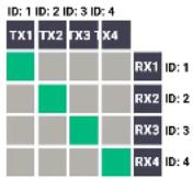
The following example demonstrates a 4x4 matrix layout and crosspoint-related commands how they can be used for crosspoint-handling. The initial state in the example is diagonal: I1-01; I2-02; I3-03; I4-04.
5.11.1. Switching an Input to an Output
▶ SET /SYS/MB/PHY.VideoChannelId=2
pw /SYS/MB/PHY.VideoChannelId=2
Above command is sent to the RX1 Decoder.
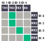
5.11.2. Switching an Input to All Outputs
SET /SYS/MB/PHY.VideoChannelId=2
pw /SYS/MB/PHY.VideoChannelId=2
Above command is sent to all Decoders separately.
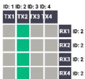
5.11.3. Switching the Source of a Video Wall
The source Encoder of an existing video wall (VW1) can be changed. In this case, the Video stream ID of the affected Decoders must be changed one-by-one.
SET /SYS/MB/PHY.VideoChannelId=4
pw /SYS/MB/PHY.VideoChannelId=4
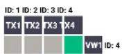
Above command is sent to all Decoders in the Video wall.
INFO: The video wall properties are not changed by switching the Encoder. Each Decoder will show the same area of the (new) image as it had been set previously.
5.11.4. Multiple Switching
The commands have to be sent to the Decoders one-by-one thus, the switching is realized in practice by setting the Video stream ID of the Decoders to the same ID as the desired Encoders.
SET /SYS/MB/PHY.VideoChannelId=4
pw /SYS/MB/PHY.VideoChannelId=4
Above command is sent to RX1.
▶ SET /SYS/MB/PHY.VideoChannelId=3
pw /SYS/MB/PHY.VideoChannelId=3
Above command is sent to RX2.
SET /SYS/MB/PHY.VideoChannelId=2
pw /SYS/MB/PHY.VideoChannelId=2
Above command is sent to RX3.
▶ SET /SYS/MB/PHY.VideoChannelId=1
pw /SYS/MB/PHY VideoChannelId=1
Above command is sent to RX4.
ID: 1 ID: 2 ID: 3 ID: 4
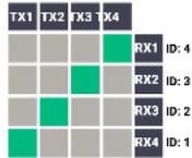


- Programmers' Reference VINX-1x0-HDMI Extenders - User's Manual 43
5.12. EDID Management (Encoder)
The Advanced EDID Management is available also by sending LW3 protocol commands. The structure of the EDID memory can be found in the EDID Menu section.
5.12.1. Querying the Emulated EDID
Command and Response
▶ GET+/EDID.EdidStatus
pr-/EDID.EdidStatus=
Parameters
Identifier Parameter description Parameter values
U1-U5: User presets
D1: The EDID of the Display Device at the local output
E1 means the Emulated EDID memory location (Input port).
INFO: There are empty slots in the Factory EDID range for future developments. See the Factory EDID List section.
Example
▶ GET /EDID.EdidStatus
pr /EDID.EdidStatus=F47:E1
Explanation
F47 EDID (Factory #47) is currently emulated on the input port of the Encoder (E1).
5.12.2. Setting the Emulated EDID on the Input Port
Command and Response
CALL·/EDID:switch(
← mO+/EDID:switch
Parameters
Identifier Parameter description Parameter values
| Source EDID memory location | F1-F132: Factory preset EDIDsU1-U5: User presetsD1: The EDID of the Display Device at the local output | |
| The emulated EDID memory of the input port | E1 |
Example
CALL /EDID:switch(F49:E2)
mO/EDID:switch
5.12.3. Copying an EDID
Command and Response
CALL·/EDID:copy(
mO+/EDID:copy
Parameters
Identifier Parameter description Parameter values
| Source EDID memory location | F1-F132: Factory preset EDIDsU1-U5: User presetsD1: The EDID of the Display Device at the local output | |
| The desired User EDID location | U1-U5 |
Example
CALL /EDID:copy(D1:U1)
mO /EDID:copy
Explanation
The EDID of the last connected sink (HDMI output, D1) has been copied to U1 User memory slot.
5.12.4. Querying the Preferred Resolution of an EDID
Command and Response
GET-/EDID/
pr-/EDID/
Parameters
Identifier Parameter description Parameter values
| The desired EDID memory type | F: Factory preset EDIDsU: User presetsD: EDID from a connected display deviceE: Emulated EDID | |
| The desired EDID memory location | F1-F132: Factory preset EDIDsU1-U5: User presetsD1: The EDID of the Display Device at the local outputE1: The emulated EDID at the input | |
| The preferred resolution in the indicated format | |
Example
▶ GET /EDID/U/U2.PreferredResolution
pr /EDID/U/U2.PreferredResolution=1920x1080p60.00Hz
INFO: Use the Manufacturer property to query the manufacturer and the MonitorName property to query the name of the monitor.


- Programmers' Reference VINX-1x0-HDMI Extenders - User's Manual 44
5.12.5. Deleting an EDID from the User Memory
Command and Response
CALL·/EDID:delete(
mO+/EDID:delete
Parameters
Identifier Parameter description Parameter values
Example
CALL /EDID:delete(U1)
mO /EDID:delete
5.13. LW3 Commands - Quick Summary
System Commands
Querying the Product Name
▶ GET·/.ProductName
Setting the Device Label
SET·/SYS/MB.DeviceLabel=
Querying the Serial Number
▶ GET·/.SerialNumber
Querying the Firmware Version
▶ GET-/SYS/MB.FirmwareVersion
Querying the Core Version
▶ GET-/SYS/MB.CoreVersion
Resetting the Device
CALL·/SYS:reset()
Restoring the Factory Default Settings
CALL·/SYS:factoryDefaults()
Network Configuration
Querying the IP Address
▶ GET-/MANAGEMENT/NETWORK.IpAddress
Querying the DHCP State
▶ GET-/MANAGEMENT/NETWORK.DhcpEnabled
Setting the DHCP State
SET/MANAGEMENT/NETWORK.DhcpEnabled=
Setting a Static IP Address
SET·MANAGEMENT/NETWORK.StaticIpAddress=
Querying the Subnet Mask
▶ GET-/MANAGEMENT/NETWORK.NetworkMask
Setting a Static Subnet Mask
SET·/MANAGEMENT/NETWORK.StaticNetworkMask=
Querying the Gateway Address
▶ GET-/MANAGEMENT/NETWORK.GatewayAddress
Setting a Static Gateway Addre
SET·/MANAGEMENT/NETWORK.StaticGatewayAddress=
Encoder-related Commands
Querying the Input Video Signal Presence
▶ GET-/MEDIA/VIDEO/
Querying the Resolution of the Input Video Signal
Querying the Video Quality Mode
▶ GET·/MEDIA/VIDEO/QUALITY.QualityMode
Setting the Video Quality Mode
SET·/MEDIA/VIDEO/QUALITY.QualityMode=
Querying the HDCP State
▶ GET-/MEDIA/VIDEO/
Setting the HDCP State
SET·/MEDIA/VIDEO/
Decoder-related Commands
Querying the Resolution of the Output Video Signal
▶ GET-/MEDIA/VIDEO/
Querying the Scaling Mode of the Output Video Signal
- GET-/MEDIA/VIDEO/
Setting the Scaling Mode of the Output Video Signal
SET·/MEDIA/VIDEO/
Setting the Resolution of the Output Video Signal
SET/MEDIA/VIDEO/
Querying the Signal Type of the Output Video Signal
- GET·/MEDIA/VIDEO/
Setting the Signal Type of the Output Video Signal
SET·/MEDIA/VIDEO/
Querying the State of the USB Connection
▶ GET-/MEDIA/KM. Controlling
Establishing the USB Connection
CALL-/MEDIA/KM:acquireControl(true)


- Programmers' Reference VINX-1x0-HDMI Extenders - User's Manual 46
Serial Port Settings
Setting the Port Availability
- SET·/MEDIA/UART/
Setting the Baud Rate of the Port
- SET·/MEDIA/UART/
Setting the RS-232 Port Mode
- SET-/MEDIA/UART/
Setting the Data Bits
- SET·/MEDIA/UART/
Setting the Stop Bits
- SET-/MEDIA/UART/
Setting the Parity
- SET·/MEDIA/UART/
Arranging the Extenders to Groups
Querying the Working Mode (Unicast/Multicast)
▶ GET-/MANAGEMENT/MULTICAST.MulticastMode
Setting the Working Mode (Unicast/Multicast)
SET·MANAGEMENT/MULTICAST.MulticastMode=
Querying the Video Stream ID Setting Method
▶ GET-/SYS/MB/PHY.ChannelIdSetBySoftware
Querying the DIP Switch Value
- GET-/SYS/MB/GPIO.DipSwitch
Querying the Video Stream ID
▶ GET-/SYS/MB/PHY.VideoChannelId
DIP Switch Enable
SET-/SYS/MB/GPIO.DipSwitchEnable=
Setting the Video Stream ID
SET-/SYS/MB/PHY.VideoChannelId=
Video Wall Settings
Setting the Name of the Video Wall
The devices can be upgraded via the built-in web page or by the Lightware Device Updater v2 (LDU2) software. The software is available at www.lightware.com. In order to get the firmware pack with the necessary components (*.lfp or *.lfp2 file) for your specific product, please contact support@lightware.com.
▶ BUILT-IN WEB OR LDU2
IMPORTANT NOTICES – BEFORE STARTING THE UPGRADE
▶ ABOUT THE FIRMWARE PACKAGE (LFP/LFP2 FILE)
▶ OPTION 1. – UPGRADING VIA THE BUILT-IN WEB PAGE
▶ OPTION 2. – UPGRADING BY LDU2
6.1. Built-in Web or LDU2
The firmware of the VINX device can be upgraded by two ways. The following table contains the features of the methods:
| Function Built-in Web LDU2 | ||
| Platform | Mozilla Firefox, Google Chrome | Windows, mac OS |
| Installation | Web browser needed only | Required |
| LFP file support | √ | - |
| LFP2 file support | √ | √ |
| Log export - | √ | |
6.2. Important Notices – Before Starting the Upgrade
- Upgrade all VINX devices within a system. Make sure that the same firmware runs on the devices. If the firmwares are different the seamless operation is not guaranteed.
- While the firmware is being upgraded signal processing is not performed. The normal operation mode is suspended as the device is switched to bootload mode.
- Do not interrupt the firmware upgrade. If any problem occurs, reboot the device and restart the process.
- The settings and parameters (e.g. User EDID memory, video wall settings) will not be lost by upgrading the firmware.
6.3. About the Firmware Package (LFP/LFP2 File)
The firmware files are packed in an LFP/LFP2 package. You need only this file to do the upgrade in your device.
- The package contains all the necessary components, binary, and other files; You do not have to get further files.
- There is a descriptor file in the package that contains each firmware with version number and a list showing the compatible devices which is displayed in Lightware Device Updater v2 (LDU2) after loading.
6.4. Option 1. – Upgrading via the Built-in Web Page
WARNING! Never disconnect the power source from the VINX devices during the upgrade! Interrupting the firmware upgrade may cause the device unusable.
This method is available by the built-in web page of the VINX device. We recommend this way of upgrade if you do not have the chance to install a software or you have just a few devices.


- Firmware Upgrade VINX-1x0-HDMI Extenders - User's Manual 48
6.4.1. Firmware Upgrading Steps
Step 1. Get the necessary firmware pack (*.Ifp or *.Ifp2 file) and save it to the control device (computer/mobile device).
Step 2. Establish the connection from the computer/mobile device to the desired VINX extender as described in the Connecting via the Built-in Web Page.
Step 3. Navigate to the Advanced Settings tab.
Step 4. Locate the Upgrade Firmware section and press the Choose file button. Browse the firmware package file and press the OK.
Step 5. Press the Upgrade Firmware button. The firmware pack will be uploaded into the device and the upgrade process is started automatically.
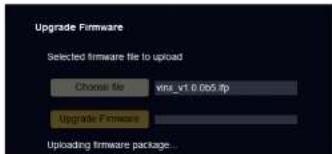
text_image
Upgrade Firmware Selected firmware file to upload Choose file vms_v1.0.065.fp Upgrade Firmware Uploading firmware package...Step 6. The progress bar and a short label will show the current state of the process.
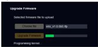
text_image
Upgrade Firmware Selected firmware file to upload Choose Re vxt_v1.0.065.fip Upgrade Firmware Programming kernelStep 7. When the programming is finished, the device will reboot and the connection will be lost. Powering off and on again the device is recommended.

INFO: LFP and LFP2 packages are also accepted for upgrading via the built-in web.
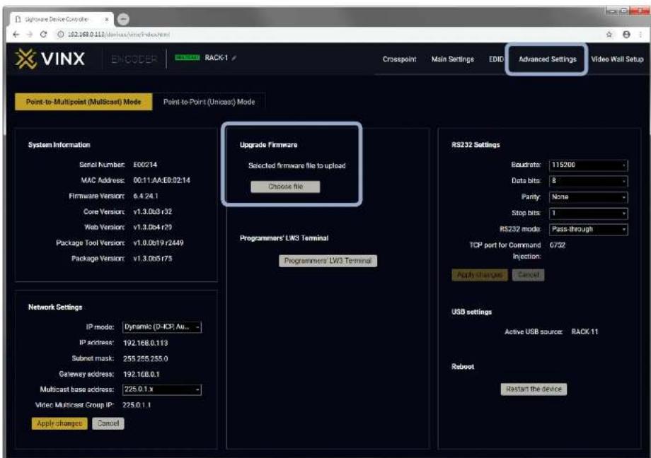
text_image
VMware Device Consolte 162.183.0.113/derivate/online/index.html VINX ENCODER RACK-1 Crosspoint Main Settings EDID Advanced Settings Video Wall Setup Point-to-Multipoint (Multicast) Mode Point-to-Point (Unicast) Mode System Information Serial Number: E00214 MAC Address: 00.11.AA.EB.02.14 Firmware Version: 6.4.24.1 Core Version: v1.3.0b3r32 Web Version: v1.3.0b4 r79 Package Tool Version: v1.0.0b19 r2449 Package Version: v1.3.0b5r75 Network Settings IP mode: Dynamic (D-ICP, Au... IP address: 192.168.0.113 Subset mask: 255.255.255.0 Gateway address: 192.168.0.1 Multicast base address: 225.0.1.x Vinec Multicast Group IP: 225.0.1.1 Apply changes Cancel Upgrade firmware Selected firmware file to upload Choose file Programmers' LW3 Terminal Programmers' LW3 Terminal RS232 Settings Baudrete: 115/200 Data bits: 8 Parity: None Stop bits: 1 RS232 mode: Pass-through TCP port for Command 6/32 Injection: Apply changes Cancel USB settings Active USB source: RACK-11 Reboot Restart the deviceFirmware Upgrade via the Built-in Web Page


- Firmware Upgrade VINX-1x0-HDMI Extenders - User's Manual 49
6.5. Option 2. - Upgrading by LDU2
The Lightware Device Updater v2 (LDU2) software is the comfortable way of upgrading the VINX devices. The advantage is that many devices can be upgraded at the same time by a few clicks.
6.5.1. Installation
INFO: After the installation the Windows and the mac applications have the same look and functionality. The mac OS version is equal with the Normal install in case of Windows and results an updateable version with the same attributes.
Installation for Windows OS
INFO: The application can be installed under Windows XP or above.
Run the installer. If the User Account Control drops a pop-up message click Yes. During the installation you will be prompted to select the type of the installation.
| Normal install Snapshot install | |
| Available for Windows and mac OS Available for Windows | |
| The installer can update only this instance Cannot be updated | |
| Only one updateable instance can exist for all users | More than one different version can be installed for all users |
Comparison of the Install Types
ATTENTION! Using the Normal install as the default value is highly recommended.
Installation for mac OS
Mount the DMG file with double clicking on it and drag the LDU2 icon over the Applications icon to copy the program into the Applications folder. If you want to copy the LDU2 into another location just drag the icon over the desired folder.
6.5.2. Before Starting the Upgrade
ATTENTION! While the firmware is being upgraded, the normal operation mode is suspended as the device is switched to bootload mode. Signal processing is not performed. Do not interrupt the firmware upgrade. If any problem occurs, reboot the device and restart the process.
ATTENTION! LFP packages cannot be used with the LDU2 software.
INFO: The settings and parameters (e.g. User EDID memory) will not be lost by upgrading the firmware.
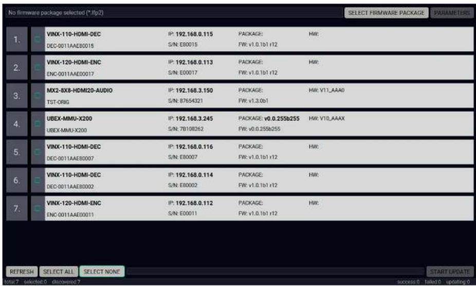
text_image
No firmware package selected (* Ifp2) SELECT FIRMWARE PACKAGE PARAMETERS 1. VINX-110-HDMI-DEC IP: 192.168.0.115 PACKAGE: HW: DEC-0011AAE00015 S/N EB0015 FW: v1.0.1b1 r12 2. VINX-120-HDMI-ENC IP: 192.168.0.113 PACKAGE: HW: ENC-0011AAE00017 S/N E00017 FW: v1.0.1b1 r12 3. MX2-BX8-HDMI20-AUDIO IP: 192.168.3.150 PACKAGE: HW: V11_AAA0 TST-ORIG S/N 87654321 FW: v1.3.0b1 4. UBEX-MMU-X200 IP: 192.168.3.245 PACKAGE: v0.0.255b255 HW: V10_AAAX UBEX-MMU-X200 S/N 7B108262 FW: v0.0.255b255 5. VINX-110-HDMI-DEC IP: 192.168.0.116 PACKAGE: HW: DEC-0011AAE80007 S/N EB0007 FW: v1.0.1b1 r12 6. VINX-110-HDMI-DEC IP: 192.168.0.114 PACKAGE: HW: DEC-0011AAE80002 S/N EB0002 FW: v1.0.1b1 r12 7. VINX-120-HDMI-ENC IP: 192.168.0.112 PACKAGE: HW: ENC-0011AAE00011 S/N E00011 FW: v1.0.1b1 r12 REFRESH SELECT ALL SELECT NONE START UPDATE Total 7 selected 0 discovered 7 success 8 failed 9 updating 9LDU2 - Device Discovery Screen


- Firmware Upgrade VINX-1x0-HDMI Extenders - User's Manual 50
6.5.3. Firmware Upgrading Steps
Step 1. Connect the computer to the same network as the VINX devices are located. Run the LDU2 software. The discovered and known devices are being loaded.

Step 2. Select the firmware package file (*.Ifp2). When the file is selected the release note is displayed in the right window. Please read it carefully.
Step 3. Press the Open button. The listed devices – which are compatible with the firmware pack – are filtered automatically in the main screen.
Step 4. Select the desired devices and press the Start Update button. The upgrade takes about 10-12 minutes to finish which is independent of the number of the upgraded devices since the upgrades are processed simultaneously.
The devices are rebooted automatically when the upgrade is finished.
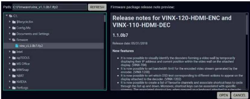
text_image
Path: C:\Firmware\vinx_v1.1.0b7\ftp2 REFRESH Firmware package release note preview: Release notes for VINX-120-HDMI-ENC and VINX-110-HDMI-DEC 1.1.0b7 Release date: 05/31/2018 New features • It is now possible to visually identify the decoders forming a video wall by temporarily displaying their IP address and current position within the video wall on the attached display, (VINX-704) • It is now possible to set bandwidth limit for the encoded video stream generated by the encoder, (VINX-1200) • It is now possible to set which OSD text corresponding to different actions to appear on the display attached to the decoder, (VINX-1202) • It is now possible to create a list of favourite channels and associate shortcut keys to cycle through the list up and down. Moreover, shortcut keys can be associated with specific strategies. The associated shortcut key when processed on a backbone attached in a decoder. OPEN CANCEL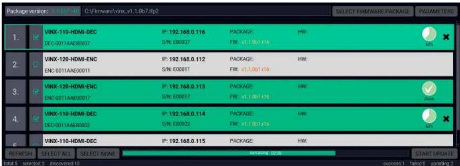
text_image
Package version: 1.1.07.40 C:\Firmware\vinc_v1.1.0b7.lfp2 SELECT FIRMWARE PACKAGE PARAMETERG 1. VINX-110-HDMI-DEC IP: 192.168.0.116 PACKAGE: HW: DEC-0011AAE80007 S/N: E00007 FW: v1.1.0b1 r16 2. VINX-120-HDMI-ENC IP: 192.168.0.112 PACKAGE: HW: ENC-0011AAE80011 S/N: E00011 FW: v1.1.0b1 r16 3. VINX-120-HDMI-ENC IP: 192.168.0.113 PACKAGE: HW: ENC-0011AAE80017 S/N: E00017 FW: v1.1.0b1 r16 4. VINX-110-HDMI-DEC IP: 192.168.0.114 PACKAGE: HW: DEC-0011AAE80022 S/N: E80002 FW: v1.1.0b1 r16 5. VINX-110-HDMI-DEC IP: 192.168.0.115 PACKAGE: HW: REFRESH SELECT ALL SELECT NONE START UPDATE Intel 5 selected 3 discovered 10 success 1 failed 2 updating 27
Troubleshooting
Usually, if the system seems not to transport the signal as expected, the best strategy for troubleshooting is to check signal integrity through the whole signal chain starting from source side and moving forward to receiver end.
Pictogram Legend
Link to the section of connections/cabling.
Link to the section of front panel operation.
Link to the section of the built-in web page.
Link to the section of LW3 protocol commands.
At first, check front panel LEDs and take the necessary steps according to their states. For more information about front and rear panel LEDs of the devices refer to the VINX Encoder Front and Rear View and VINX Decoder Front and Rear View sections.
| Symptom Root cause Action Refer to | |||
| Video issues | |||
| No video on the screen | No video signal on the input. | Check the source and the cable connections. | ↑1 |
| The Video Stream IDs are different. | Check the settings of the extenders and assign them. | 4.4.1 | |
| HDCP is disabled (EDID information cannot be read) | Enable the HDCP on the input of the Encoder. (In certain cases, the source device cannot read the EDID from the Encoder.) | 4.4.2 | |
| HDCP-encrypted content sent to a non-HDCP sink. | Replace the sink to a HDCP-capable one. | ||
| Network issues | |||
| Cannot connect to an extender | The extenders did not get IP address. | The Ethernet switch needs more time to be ready than the extenders. Reboot the VINX devices. | |
| The extender is not connected. | Check the LEDs and the cable connections. 3.1 | 3.2 | |
| The extenders and the PC are not in the same subnet. | Make sure the devices are located in the same subnet. | ||
| USB issues | |||
| The video stream cannot be changed by the keyboard shortcut | The keyboard is connected to an USB 2.0 port. | Connect the keyboard to the USB 1.1 port. | ↑1 |
| Shortcut is not assigned properly. | Check the settings and set the shortcut(s) again. | 4.4.1 | |
| The keyboard is connected to another Decoder. | Connect it to the desired Decoder. | ↑1 | |
| USB data transmission does not work | Another Decoder is selected for USB transmission. | Check the LEDs or the USB settings in the built in web page. | 3.2 |
| 4.7.2 | |||
| The Encoder and the computer are not connected over USB. | Connect the supplied USB cable between the computer and the Encoder. | ↑1 | |

Technologies
The following sections contain descriptions and useful technical information how the devices work in the background. The content is based on experiences and cases we met in the practice. These sections help to understand features and technical standards like the followings:
▶ EDID MANAGEMENT
VIDEO OVER IP
HDCP MANAGEMENT
8.1. EDID Management
8.1.1. Understanding the EDID
The Extended Display Identification Data (EDID) is the passport of display devices (monitors, TV sets, projectors). It contains information about the capabilities of the display, such as supported resolutions, refresh rates (these are called Detailed Timings), the type and manufacturer of the display device, etc.
After connecting a source to a display (DVI, HDMI, DP), the source reads out the EDID to determine the resolution and refresh rate of the image to be transmitted.
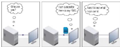
EDID Communication
Most DVI computer displays have 128-byte long EDID structure. However, Digital Televisions and HDMI capable displays may have another 128 bytes, which is called E-EDID and defined by CEA (Consumer Electronics Association). This extension contains information about additional Detailed Timings, audio capabilities, speaker allocation and HDMI capabilities. It is important to know that all HDMI capable devices must have CEA extension, but not all devices with CEA extension are HDMI capable.
Common Problems Related to EDID
Problem: "My system consists of the following: a computer, a Lightware device, a WUXGA (1920x1200) LCD monitor, and an SXGA (1280x1024) projector. I would like to see the same image on the monitor and the projector. What EDID should I choose on the Lightware device?"
Solution: If you want to see the image on both displays, you need to select the resolution of the smaller display (in this case SXGA), otherwise the smaller display may not show the higher resolution image.
Problem: "I have changed to a different EDID on an input port of the Lightware device to have a different resolution but nothing happens."
Solution: Some graphics cards and video sources read out the EDID only after power-up and later they do not sense that EDID has been changed. You need to restart your source to make it read out the EDID again.
8.1.2. Advanced EDID Management
Each DVI sink (e.g. monitors, projectors, plasma displays, etc...) must support the EDID data structure. Source BIOS and operating systems are likely to query the sink using DDC2B protocol to determine what pixel formats and interface are supported. DVI standard uses EDID data structure to identify the monitor type and capabilities. Most DVI sources (VGA cards, set top boxes, etc.) will output DVI signal after accepting the connected sink's EDID information. In the case of EDID readout failure or missing EDID, the source will not output DVI video signal.
Lightware devices provide the Advanced EDID Management function that helps system integration. The built-in EDID Router can store and emulate factory pre-programmed- and User programmable EDIDs. The EDID of the attached monitors or projectors for each output are stored in a non-volatile memory. This way the EDID of a monitor is available when the monitor is unplugged or switched off.
INFO: The user is not required to disconnect the video cable to change an EDID as opposed to other manufacturer's products. EDID can be changed even if a source is connected to the input and powered ON.
INFO: When EDID has been changed, the router toggles the HOTPLUG signal for 2 seconds. Some sources do not sense this signal. In such cases, the source device must be restarted or powered OFF and ON again.
8.2. Video Over IP
Basics
Beside the traditional AV matrix switchers and extenders the video over IP or networked AV system is the biggest leading technology in the AV industry. The spreading of the technology speeds up the general increasing of the using of the IT-related devices and equipment all around the world - from the offices to the homes.
The main difference compared with the traditional AV technologies is the method of the signal transmission: the networked AV transmitter/encoder devices convert the video signal to TCP/IP packets and transfer them to the receivers/decoders. The interface of the transmission can be CATx or fiber optical cable depending on the signal bandwidth and the distance between the source and sink devices.
What is TCP/IP?
DEFINITION: TCP/IP, or the Transmission Control Protocol/Internet Protocol, is a suite of communication protocols used to interconnect network devices on the Internet or in a private network.
TCP/IP specifies how data is exchanged over the network by providing end-to-end communications that identify how it should be broken into packets, addressed, transmitted, routed and received at the destination. TCP/IP requires little central management, and it is designed to make networks reliable, with the ability to recover automatically from the failure of any device on the network. *
The two main protocols in the Internet protocol suite serve specific functions. TCP defines how applications can create channels of communication across a network. It also manages how a message is assembled into smaller packets before they are then transmitted over the Internet and reassembled in the right order at the destination address.*
IP defines how to address and route each packet to make sure it reaches the right destination. Each gateway computer on the network checks this IP address to determine where to forward the message.*
* Source: https://searchnetworking.techtarget.com/definition/TCP-IP
8.3. HDCP Management
Lightware Visual Engineering is a legal HDCP adopter. Several functions have been developed which helps to solve HDCP related problems. Complex AV systems often have both HDCP and non-HDCP components. The matrix allows transmitting HDCP encrypted and unencrypted signals. The devices will be still HDCP compliant as they will never output an encrypted signal to a non-HDCP compliant display device. If an encrypted signal is switched to a non-compliant output, a red screen alert or muted screen will appear.
8.3.1. Protected and Unprotected Content
Many video sources send HDCP protected signal if they detect that the sink is HDCP capable – even if the content is not copyrighted. This can cause trouble if an HDCP capable device is connected between the source and the display. In this case, the content cannot be viewed on non-HDCP capable displays and interfaces like event controllers. Rental and staging technicians often complain about certain laptops, which are always sending HDCP encrypted signals if the receiver device (display, matrix router, etc.) reports HDCP compliancy. However, HDCP encryption is not required all the time e.g. computer desktop image, certain laptops still do that.
To avoid unnecessary HDCP encryption, Lightware introduced the HDCP enabling/disabling function: the HDCP capability can be disabled in the Lightware device. If HDCP is disabled, the connected source will detect that the sink is not HDCP capable, and turn off authentication.
8.3.2. Disable Unnecessary Encryption
HDCP Compliant Sink
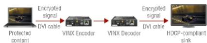
flowchart
graph LR
    A["Protected content"] -->|Encrypted signal DVI cable| B["VINX Encoder"]
    B -->|Encrypted signal DVI cable| C["VINX Decoder"]
    C -->|Encrypted signal DVI cable| D["HDCP-compliant sink"]
All the devices are HDCP-compliant, no manual setting is required, both protected and unprotected contents are transmitted and displayed on the sink.
Not HDCP-compliant Sink 1.
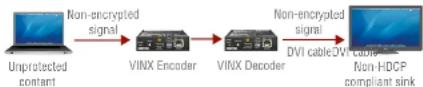
Non-HDCP compliant sink is connected to the matrix. Some sources (e.g. computers) always send HDCP encrypted signals if the receiver device reports HDCP compliancy, however, HDCP encryption is not required all the time (e.g. computer desktop image). If HDCP is enabled in the matrix, the image will not be displayed on the sink.
Setting the HDCP parameter to Auto on the output port and disable HDCP on the input port, the transmitted signal will not be encrypted if the content is not protected. Thus, non-HDCP compliant sinks will display non-encrypted signal.
Not HDCP-compliant Sink 2.
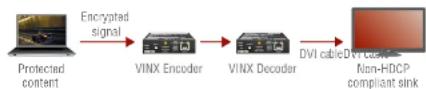
The layout is the same as in the previous case: non-HDCP compliant display device is connected to the matrix but the source would send protected content with encryption. If HDCP is enabled on the input port of the matrix, the source will send encrypted signal. The sink is not HDCP compliant, thus, it will not display the video signal (but blank/red/muted/etc. screen). If HDCP is disabled on the input port of the matrix, the source will not send the signal. The solution is to replace the display device to an HDCP-capable one.


- Appendix VINX-1x0-HDMI Extenders - User's Manual 54
9
Appendix
Tables, drawings, guides, and technical details as follows:
SPECIFICATIONS
MECHANICAL DRAWINGS
▶ OUTPUT RESOLUTIONS (SCALER)
FACTORY DEFAULT SETTINGS
FACTORY EDID LIST
DIP SWITCH STATES
▶ APPLICATION NOTE (LW-AN-001)
FURTHER INFORMATION
9.1. Specifications
General
Compliance......CE
EMC Compliance (Emission) .....IEC/EN 55032:2015
EMC Compliance (Immunity)....IEC/EN 55024:2011
Warranty 3 years
Cooling....Passive
Operating Temperature....0 to +40°C (+32 to +122°F)
Operating Humidity....10% to 90%, non-condensing
Power
Power Supply .... External power adaptor (supplied)
Power Adaptor ....In 100-240 V AC 50/60 Hz, Out 5V DC, 3 A
Power Consumption (Decoder) 5 W (max)
Power Consumption (Encoder)....8.5 W (max)
Enclosure
Material....1 mm steel
Dimensions in mm....100.4W x 115D x 26H
Dimensions in inch 3.95W x 4.53D x 1.02H
Weight 375 g
Video Ports
Input/Output Port Types....19-pole HDMI type A receptacle
Supported Standards.....DVI 1.0, HDMI 2.0
3D signal support..... 'Side-by-side' and 'Top-to-bottom' modes
Supported Resolutions up to 3840x2160p@30Hz
HDCP Compliance Yes, v2.2
Audio Support .... Embedded LPCM, Dolby Digital,
Dolby Digital Plus, DTS, Dolby TrueHD, DTS-HD bit stream
Data Communication Ports
USB Ports
USB Port Type (Encoder)....mini-B type receptacle
USB Port Type (Decoder).....type A receptacle, 4 pcs.
2 pcs. USB 1.1 and 2 pcs. USB 2.0 compliant
Data Communication Mode......Transparent
RS-232 Ports
Serial Port Type....RJ12 female receptacle
Supported Baud Rates.
300, 600, 1200, 2400, 4800, 9600, 19200, 38400, 57600, 115200
Supported Data Bit Settings....6,7,8
Supported Parity Settings ....none, odd, even
Supported Stop Bit Settings....1,2
. Duplex, transparent
Infrared Ports
IR Port Type (Encoder)....3.5mm Jack TRS (IR output)
IR Port Type (Decoder) 3.5mm Jack TRS (IR input)


- Appendix VINX-1x0-HDMI Extenders - User's Manual 55
9.2. Mechanical Drawings
INFO: The dimensions of the Encoder and Decoder devices are the same.
Front View weiV motto
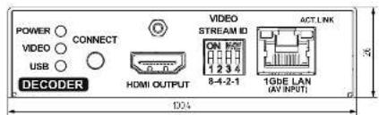
natural_image
Pure electrical circuit lines without any symbolsLIGHTWARE
VINX-110-HDMI-DEC
1-output decoder with HDMI connector
HDMI 1.4
Bidirectional RS-232
USB HID extension
CONNECT button (for further details please see the User's manual) Short press: Acquire USB connection in multicast mode Long press: Reset to factory defaults
Video Stream ID
0: Receive stream with Video Stream ID set via software 1-15: Receive stream with fixed Video Stream ID set by the switch
Front LEDs
POWER
OFF: No power
Blinking: Booting Continuous: Power connected
VIDEO
OFF: No connection with ENCODER Blinking: Connected to ENCODER, no video output Continuous: Connected to ENCODER, video output
USB
OFF: No USB connection
Continuous: USB connection acquired

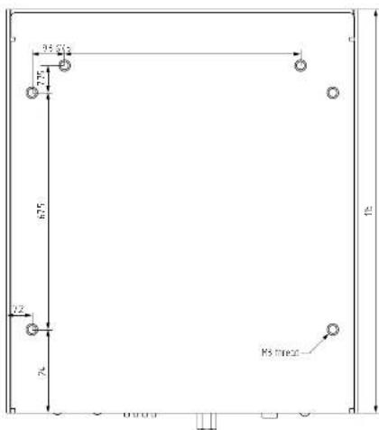
text_image
35.02 7.76 6.75 1.2 R3 line29.3. Output Resolutions (Scaler)
| Resolution Frame rate HEX identifier | ||
| 640x480 50 81004054 | ||
| 640x480 60 80000001 | ||
| 640x480 72 81004004 | ||
| 640x480 75 81004005 | ||
| 720x480 (480p) 60 81000002 | ||
| 720x576 (576p) 50 80000011 | ||
| 800x600 50 81004059 | ||
| 800x600 60 8100405A | ||
| 800x600 72 81004009 | ||
| 800x600 75 8100400A | ||
| 1024x768 50 8100405E | ||
| 1024x768 60 8100405F | ||
| 1024x768 75 81004060 | ||
| 1152x864 60 8100403E | ||
| 1280x720 (720p) 50 80000013 | ||
| 1280x720 (720p) 60 80000004 | ||
| 1280x720 (720p) 75 81004089 | ||
| 1280x768 50 8100407B | ||
| 1280x768 60 8100407C | ||
| 1280x768 75 81004015 | ||
| 1280x800 60 81004040 | ||
| 1280x800 75 81004042 | ||
| 1280x960 50 81004063 | ||
| 1280x960 60 81004064 | ||
| 1280x1024 50 81004076 | ||
| 1280x1024 60 81004077 | ||
| 1280x1024 75 81004078 | ||
| 1360x768 50 8100408C | ||
| 1360x768 60 8100408D | ||
| 1360x768 75 8100408E | ||
| Resolution Frame rate HEX identifier | ||
| 1366x768 60 81004048 | ||
| 1440x900 60 81004021 | ||
| 1440x900 75 81004023 | ||
| 1600x900 60 8100404E | ||
| 1600x1024 60 810040EF | ||
| 1600x1200 50 8100406A | ||
| 1600x1200 60 8100406B | ||
| 1680x1050 50 810040C1 | ||
| 1680x1050 60 810040C2 | ||
| 1920x1080i 25 80000014 | ||
| 1920x1080i 29.97 80000005 | ||
| 1920x1080 (1080p) 50 8000001F | ||
| 1920x1080 (1080p) 60 80000010 | ||
| 1920x1200 50 810040C8 | ||
| 1920x1200 60 81004032 | ||
| 2560x1080 24 81000071 | ||
| 2560x1080 25 81000072 | ||
| 2560x1080 30 81000073 | ||
| 2560x1080 50 81000074 | ||
| 2560x1080 60 81000075 | ||
| 2560x1200 30 810040F0 | ||
| 2560x1200 60 810040F1 | ||
| 2560x1600 60 81004053 | ||
| 3840x2160 24 8000005D | ||
| 3840x2160 25 8000005E | ||
| 3840x2160 30 8000005F | ||
| 4096x2160 24 80000062 | ||
| 4096x2160 25 80000063 | ||
| 4096x2160 30 80000064 | ||
9.4. Factory Default Settings
| Parameter | Setting/Value |
| IP address | Dynamic (DHCP is enabled) |
| RS-232 port setting | 115200 BAUD, 8, N, 1 |
| DIP switch state | 0000 |
| Connecting method | Multicast mode |
| Emulated EDID | F47 Factory preset(Universal HDMI EDID) |
| User EDID memory | Empty (cleared) |
| Output video mode (Encoder) | Video mode |
| Output scaling (Decoder) | Pass-through, no rotation |
| Available video walls | Empty (cleared) |
9.5. Factory EDID List
| Mem. Resolution Type | |||||
| F1 640 x 480 @ 60.00 Hz D | |||||
| F3 800 x 600 @ 60.32 Hz D | |||||
| F4 1024 x 768 @ 60.00 Hz D | |||||
| F5 1280 x 768 @ 50.00 Hz D | |||||
| F6 1280 x 768 @ 59.94 Hz D | |||||
| F7 1280 x 768 @ 75.00 Hz D | |||||
| F8 1360 x 768 @ 60.02 Hz D | |||||
| F9 1280 x 1024 @ 50.00 Hz D | |||||
| F10 1280 x 1024 @ 60.02 Hz D | |||||
| F11 1280 x 1024 @ 75.02 Hz D | |||||
| F15 1680 x 1050 @ 60.00 Hz D | |||||
| F16 1920 x 1080 @ 50.00 Hz D | |||||
| F17 1920 x 1080 @ 60.00 Hz D | |||||
| F20 1600 x 1200 @ 50.00 Hz D | |||||
| F21 1600 x 1200 @ 60.00 Hz D | |||||
| F22 1920 x 1200 @ 50.00 Hz D | |||||
| F23 1920 x 1200 @ 59.56 Hz D | |||||
| F29 1920 x 1080 @ 60.00 Hz U | |||||
| F32 640 x 480 @ 59.95 Hz H | |||||
| F33 720 x 480 @ 59.94 Hz H | |||||
| F34 720 x 576 @ 50.00 Hz H | |||||
| F35 1280 x 720 @ 50.00 Hz H | |||||
| F36 1280 x 720 @ 60.00 Hz H | |||||
| F37 1920 x 1080 @ 50.04 Hz H | |||||
| F38 1920 x 1080 @ 50.00 Hz H | |||||
| F39 1920 x 1080 @ 60.05 Hz H | |||||
| F40 1920 x 1080 @ 60.05 Hz H | |||||
| F41 1920 x 1080 @ 24.00 Hz H | |||||
| F42 1920 x 1080 @ 25.00 Hz H | |||||
| F43 1920 x 1080 @ 30.00 Hz H | |||||
| Mem. Resolution Type | |||||
| F44 1920 x 1080 @ 50.00 Hz H | |||||
| F45 1920 x 1080 @ 60.00 Hz H | |||||
| F46 1920 x 1080 @ 60.00 Hz H | |||||
| F47 1920 x 1080 @ 60.00 Hz U | |||||
| F48 1920 x 1080 @ 60.00 Hz U | |||||
| F49 1920 x 1080 @ 60.00 Hz U | |||||
| F96 2560 x 1600 @ 59.86 Hz D | |||||
| F100 | 1024 x | 768 @ 60 | 00 Hz H | ||
| F101 | 1280 x | 1024 @ 5 | 0.00 Hz H | ||
| F102 | 1280 x | 1024 @ 6 | 0.02 Hz H | ||
| F103 | 1280 x | 1024 @ 7 | 5.02 Hz H | ||
| F104 | 1600 x | 1200 @ 5 | 0.00 Hz H | ||
| F105 | 1600 x | 1200 @ 6 | 0.00 Hz H | ||
| F106 | 1920 x | 1200 @ 5 | 9.56 Hz H | ||
| F108 | 2560 x | 1600 @ 5 | 9.96 Hz H | ||
| F110 | 3840 x | 2160 @ 24 | 4.00 Hz H | ||
| F111 | 3840 x | 2160 @ 25 | 5.00 Hz H | ||
| F112 | 3840 x | 2160 @ 30 | 0.00 Hz H | ||
| F118 | 3840 x | 2160 @ 30 | 0.00 Hz U | ||
| F119 | 3840 x | 2160 @ 30 | 0.00 Hz U | ||
| F125 | 1366 x | 768 @ 60 | 00 Hz H | ||
| F131 | 4096 x | 2160 @ 25 | 0.00 Hz H | ||
| F132 | 4096 x | 2160 @ 30 | 0.00 Hz H | ||
Legend
D: DVI EDID
H: HDMI EDID
U: Universal EDID (supporting many standard resolutions)
Please note that minor changes in the factory EDID list may be applied in farther firmware versions.
Universal EDIDs
The Universal EDIDs include many common resolutions with the below features:
• F29: Universal EDID for DVI signals (no audio support).
• F47: HDMI EDID with supporting PCM audio.
• F48: HDMI EDID with supporting all type of audio.
• F49: HDMI EDID with supporting all type of audio and deep color.
• F118: HDMI EDID with supporting PCM audio and 4K@30 Hz signals.
• F119: HDMI EDID with supporting all type of audio and 4K@30 Hz signals.
9.6. DIP Switch States
| DIP switch state | Video Stream ID | /SYS/MB/GPIO.DipSwitch value |
| 0000 | SW setting | 0x0 |
| 0001 | 1 | 0x1 |
| 0010 | 2 | 0x2 |
| 0011 | 3 | 0x3 |
| 0100 | 4 | 0x4 |
| 0101 | 5 | 0x5 |
| 0110 | 6 | 0x6 |
| 0111 | 7 | 0x7 |
| 1000 | 8 | 0x8 |
| 1001 | 9 | 0x9 |
| 1010 | 10 | 0xa |
| 1011 | 11 | 0xb |
| 1100 | 12 | 0xc |
| 1101 | 13 | 0xd |
| 1110 | 14 | 0xe |
| 1111 | 15 | 0xf |
9.7. Application Note (LW-AN-001)
Gigabit Network Switch Requirements For VINX Devices
Network Properties
Network-based AV products use different network protocols for different operations. The network protocol can be UDP/IP and TCP/IP, the transmission mode can be Broadcast, Unicast, and Multicast.
These network protocols should be familiar to any network engineer. Because our network-based AV solutions bridge the gap between the audio-visual (AV) and information technology (IT) worlds, Lightware suggests involvement of both AV and IT departments in any installation.
Lightware products are designed to be plug-and-play. The figures in the next section illustrate the basic installation of one Decoder and one Encoder. A video source provides the digital video content to the Encoder which converts to Ethernet packets and sends to the attached Decoder. The Decoder reconstitutes the video with synchronized audio for presentation to the attached display.
Point-to-point vs Network Connection
VINX Encoders and Decoders have two typical applications:
- Point-to-point connection
- Point-to-multi point connection
Point-to-point Connection (Unicast mode)
Unicast transmission mode uses a one-to-one association between the source and the destination: each destination address uniquely identifies a single Decoder endpoint.

Point-to-Multi Point Connection (Multicast mode)
Multicast transmission mode uses a one-to-one or one-to-many association; multicast datagrams are forwarded simultaneously in a single transmission to many recipients through L2 swithed network. There can be multiple encoders in a L2 subnet. The decoders has to be in the same subnet.

Unicast Routing
The packet forwarding requirement of the VINX devices for point-to-point connection is the unicast switching. Please note the unicast mode is not the default setting of the Encoder and Decoder, users have to set it in the devices.
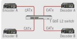
flowchart
graph LR
    A["Encoder A"] -->|CATx| C["1 GbF L2 switch"]
    B["Encoder B"] -->|CATx| C
    D["Decoder A"] -->|CATx| C
    E["Decoder B"] -->|CATx| C
Hardware Requirement:
• 1 GbE Layer 2 (L2) switch
ATTENTION! VINX devices send certain system commands over multicast packages. If the multicast packet forwarding is disabled on the network, the signal transmission can fail.
Managed Switch for Multicast Routing
In TCP/IP terminology Layer 2 is the data link layer that is responsible for splitting the information coming from higher layers in the TCP/IP stack into Ethernet frames. An Ethernet frame includes, among others, labeling information with source and destination physical addresses (called source and destination MAC address). These physical addresses uniquely identify the source and destination physical devices (e.g. a VINX Encoder and a VINX Decoder). Ethernet frames provide error resilience by incorporating a redundancy check field through which transmission errors can easily be detected. The device that uses only the physical address information found in the Ethernet frame to forward a packet from one of its input ports to one or more of its output ports is an unmanaged switch.
A managed switch, on the other hand, can handle the traffic and forward input packets to output packets by utilizing information from higher layers. This gives the managed switch more flexibility and also allows for more sophisticated functions like multicast forwarding. Since even a simple VINX network, where one VINX Encoder supplies more VINX Decoders, relies on multicasting, a multicast capable switch (i.e. a managed one) is mandatory. If non-managed switches transmit the multicast packages, the multicast traffic is usually broadcasted over all interfaces.
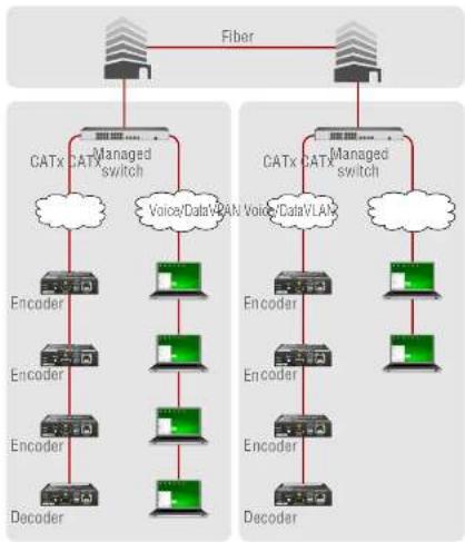
Hardware Requirement:
• 1 GbE Layer 3 (L3) switch or managed L2 switch
Why is it important?
By default, Lightware Video-over-IP Encoders and Decoders use multicast packet forwarding. The switches in the network shall offer the following capabilities:
- IGMPv2
- IGMP snooping
- IGMP fast leave
- IGMP Querier
- Multicast filtering
• 9k MTU - Jumbo/Giant frames
Managed Switch Properties in Details
IGMPv2
IGMPv2 is version 2 of the Internet Group Management Protocol. This protocol is used by end-point devices to signal their interest in receiving a specific multicast content via subscribing to the multicast group corresponding to the content. Using IGMPv2 packets, the end-point devices can send a leave message to indicate that they are no longer interested in receiving the stream of the multicast group. Moreover, a multicast capable router can periodically poll the end-point devices on its interfaces which multicast streams are interested to receive. The answer to such a query is called a membership report. IGMPv2 must be supported by the managed switch.
IGMP Snooping
IGMP snooping is a feature which allows the switch to monitor IGMP traffic when enabled. The information collected from the IGMP packets is used by the managed switch to determine which interfaces the multicast traffic should be forwarded to. In other words, IGMP snooping is used to converse bandwidth by allowing the switch to forward multicast traffic to those interfaces where it is really required.
IGMP Fast Leave
IGMP fast leave (or immediate leave), when configured, reduces the amount of time it takes for the managed switch to stop sending multicast traffic (corresponding to a multicast group defined by a multicast address) to an interface, where all end-point devices that used to be interested in a stream have sent a IGMP leave message. Without fast leave being enabled the managed switch would first send out a query message and then would stop forwarding when no endpoints answered within a pre-specified time interval. If fast leave is enabled, the switch stops forwarding the traffic without sending a query message.
IGMP Querier
In order for IGMP snooping to work properly, IGMP messages must traverse in the subnet between managed switches. However, if there is no multicast capable router present periodically sending out query messages and receiving answers to those queries, IGMP messages are usually not forwarded upstream from one switch to another. By enabling the IGMP querier feature in a managed switch, the managed switch will act like a router and periodically query the devices in the subnet (even other managed switches) to send their membership reports. From those report all the listening switches with IGMP snooping enabled will be able to determine where multicast traffic should be sent to.
Multicast Filtering
Some control information from VINX devices is transmitted via multicast packets. However, these packets are not registered during certain startup intervals or not registered at all. In order for all VINX devices in the subnet to receive such control information, multicast filtering must be set up, so that unregistered groups are forwarded to all interfaces on the managed switch.
Jumbo/Giant Frames
Ethernet frames consist of a header and a payload. Since the header has a fixed length (20 or 26 bytes) the bigger the payload, the higher the useful bandwidth is. Similarly, the higher the useful bandwidth, the better the picture quality of the encoded video stream will be. To maximize picture quality, the Ethernet frame size (and consequently, the payload) should be as high as possible. In a normal Ethernet frame, the payload can be at most 1500 bytes. An Ethernet jumbo frame, however, can carry up to 9000 bytes of payload. Since the goal of the transmission is to provide the best possible picture quality in all circumstances, the VINX Encoder device produces Ethernet jumbo frames. Thus, the handling of jumbo frames has to be enabled in the managed switches.
9.8. Further Information
Limited Warranty Statement
- Lightware Visual Engineering LLC (Lightware) warrants to all trade and end user customers that any Lightweight product purchased will be free from manufacturing defects in both material and workmanship for three (3) years from purchase unless stated otherwise below. The warranty period will begin on the latest possible date where proof of purchase/delivery can be provided by the customer. In the event that no proof can be provided (empty 'Date of purchase' field or a copy of invoice), the warranty period will begin from the point of delivery from Lightweight.
1.1. 25G and MODEX product series will be subject to a seven (7) year warranty period under the same terms as outlined in this document.
1.2. If during the first three (3) months of purchase, the customer is unhappy with any aspect of a Lightware product, Lightware will accept a return for full credit.
1.3. Any product that fails in the first six (6) months of the warranty period will automatically be eligible for replacement and advanced replacement where available. Any replacements provided will be warranted for the remainder of the original unit's warranty period.
1.4. Product failures from six (6) months to the end of the warranty period will either be repaired or replaced at the discretion of Lightware. If Lightware chooses to replace the product then the replacement will be warranted for the remainder of the original unit's warranty period. - The above-stated warranty and procedures will not apply to any product that has been:
2.1. Modified, repaired or altered by anyone other than a certified Lightware engineer unless expressly agreed beforehand.
2.2. Used in any application other than that for which it was intended. 2.3. Subjected to any mechanical or electrical abuse or accidental damage.
2.4. Any costs incurred for repair/replacement of goods that fall into the above categories (2.1., 2.2., 2.3.) will be borne by the customer at a pre-agreed figure. - All products to be returned to Lightware require a return material authorization number (RMA) prior to shipment and this number must be clearly marked on the box. If an RMA number is not obtained or is not clearly marked on the box, Lightware will refuse the shipment.
3.1. The customer will be responsible for in-bound and Lightware will be responsible for out-bound shipping costs.
3.2. Newly repaired or replaced products will be warranted to the end of the originally purchased products warranty period.
Document Revision History
| Rev. | Release date | Changes Editor | |
| 1.0 | 21-12-2017 | Initial release. | Laszlo Zsedenyi |
| 1.1 | 19-02-2018 | Minor corrections. | Laszlo Zsedenyi |
| 1.2 | 23-03-2018 | Built-in website chapter updated. | Laszlo Zsedenyi |
| 1.3 | 08-06-2018 | Accessories list expanded, Built-in web revised (updated screens and content according to firmware 1.1.0), USB key shortcut feature added. Programmers' reference revised, Lightware Device Updater v2 added, Troubleshooting added, Video over IP technology description added, Factory EDID list updated. | Laszlo Zsedenyi |
| 1.4 | 24-10-2018 | Addition to LW3 commands; minor changes due to new firmware; signal diagrams refined. | Laszlo Zsedenyi |
| 1.5 | 1-01-2019 | Crosspoint view added to SW control; Crosspoint switching examples added; Mounting into Rackmount-cage added; FW upgrade section upgraded; Minor graphical updates | Laszlo Zsedenyi |
Contact Us
sales@lightware.com
+36 1 255 3800
support@lightware.com
+36 1 255 3810
Lightware Visual Engineering LLC.
Peterdy 15, Budapest H-1071, Hungary
www.lightware.com
©2019 Lightware Visual Engineering. All rights reserved. All trademarks mentioned are the property of their respective owners. Specifications subject to change without notice.