HDMI-OPT-TX200R - Audio/video extender Lightware - Free user manual and instructions
Find the device manual for free HDMI-OPT-TX200R Lightware in PDF.


User questions about HDMI-OPT-TX200R Lightware
0 question about this device. Answer the ones you know or ask your own.
Ask a new question about this device
Download the instructions for your Audio/video extender in PDF format for free! Find your manual HDMI-OPT-TX200R - Lightware and take your electronic device back in hand. On this page are published all the documents necessary for the use of your device. HDMI-OPT-TX200R by Lightware.
USER MANUAL HDMI-OPT-TX200R Lightware
natural_image
Three black industrial electronic devices with indicator lights and ports, no visible text or labels on the device bodies.HDMI-OPT-TX100, HDMI-OPT-RX100
HDMI-OPT-TX100R, HDMI-OPT-RX100R
HDMI-OPT-TX200R, HDMI-OPT-RX200R
Fiber Optical Multimedia Extender
Important Safety Instructions
Class II apparatus construction.
The equipment should be operated only from the power source indicated on the product.
To disconnect the equipment safely from power, remove the power cord from the rear of the equipment, or from the power source. The MAINS plug is used as the disconnect device, the disconnect device shall remain readily operable.
There are no user-serviceable parts inside of the unit. Removal of the cover will expose dangerous voltages. To avoid personal injury, do not remove the cover. Do not operate the unit without the cover installed.
The appliance must be safely connected to multimedia systems. Follow instructions described in this manual.
Ventilation
For the correct ventilation and to avoid overheating ensure enough free space around the appliance. Do not cover the appliance, let the ventilation holes free and never block or bypass the ventilators (if any).
WARNING
To prevent injury, the apparatus is recommended to securely attach to the floor/wall or mount in accordance with the installation instructions. The apparatus shall not be exposed to dripping or splashing and that no objects filled with liquids, such as vases, shall be placed on the apparatus. No naked flame sources, such as lighted candles, should be placed on the apparatus.
Waste Electrical & Electronic Equipment WEEE
This marking shown on the product or its literature, indicates that it should not be disposed with other household wastes at the end of its working life. To prevent possible harm to the environment or human health from uncontrolled waste disposal, please separate this from other types of wastes and recycle it responsibly to promote the sustainable reuse of material resources. Household users should contact either the retailer where they purchased this product, or their local government office, for details of where and how they can take this item for environmentally safe recycling. Business users should contact their supplier and check the terms and conditions of the purchase contract. This product should not be mixed with other commercial wastes for disposal.
Caution: Laser product


Common Safety Symbols
| Symbol Description | |
 | Direct current |
 | Alternating current |
| [3BDT] | Double insulation |
 | Caution, possibility of eletric shock |
 | Caution |
 | Laser radiation |


HDMI-OPT series – User's Manual 3
Symbol Legend
The following symbols and markings are used in the document:
WARNING! Safety-related information which is highly recommended to read and keep in every case!
ATTENTION! Useful information to perform a successful procedure; it is recommended to read.
INFO: A notice which may contain additional information. Procedure can be successful without reading it.
DEFINITION: The short description of a feature or a function.
TIPS AND TRICKS: Ideas which you may have not known yet but can be useful.
Navigation Buttons
Go back to the previous page. If you clicked on a link previously, you can go back to the source page by clicking the button.
Navigate to the Table of Contents.
Step back one page.
Step forward to the next page.
Document Information
All presented functions refer to the indicated products. The descriptions have been made during testing these functions in accordance with the indicated Hardware/Firmware/Software environment:
| Item Version | |
| Lightware Device Controller (LDC) software | 1.23.2b1 |
| Lightware Bootloader Software | 3.3.3 |
| Controller firmware - HDMI-OPT-TX series | 1.9.7.b1 |
| Controller firmware - HDMI-OPT-RX series | 1.9.7.b1 |
| Hardware | 2.0 |
Document revision: 3.0
Release date: 13-08-2018
Editor: Judit Barsony
About Printing
Lightware Visual Engineering supports green technologies and eco-friend mentality. Thus, this document is made for digital usage primarily. If you need to print out few pages for any reason, follow the recommended printing settings:
- Page size: A4
- Output size: Fit to page or Match page size
- Orientation: Landscape
TIPS AND TRICKS: Thanks to the size of the original page, the border around the content (grey on the second picture below) makes possible to organize the pages better. After punching the printed pages, they can be placed easily into a ring folder.
1

2

3

Table of Contents
- INTRODUCTION 5
1.1.DESCRIPTION ....5
1.2. BOX CONTENTS .... 5 1.3. MODEL COMPARISON .... 5
1.3. MODEL COMPARISON ....5 1.4. FEATURES OF THE DEVICE ....6
1.5.COMPARITIBLE DEVICES 6
1.6. TYPICAL APPLICATION 6
- INSTALLATION....7
2.1.MOUNTING OPTIONS....7
2.1.1. 1U High Rack Shelf....7
2.1.2. Under-desk Mounting Kit
2.1.3. Under-desk Double Mounting Kit..../
2.2. CONNECTING STEPS....8 2.2.1. Read Rate Settings 9
2.2.1. Bond Rate Settings 9
- PRODUCT OVERVIEW ....10
3.1. HDMI-OPT SERIES RECEIVERS 10
3.2. HDMI-OPT SERIES TRANSMITTERS....11
3.3. ELECTRICAL CONNECTIONS....12
3.3.1. DC 5V Connection ..... 12
3.3.2.HDMI Inputs and Outputs 12
3.3.3.SG Fiber Input and Output 12
3.3.3. SC Fiber Input and Output 12 3.3.4. PS-232 Connectors 12
3.4. OPTICAL EXTENDER CONCEPT 13
3.5. HDMI OUTPUT SETTINGS....13
3.6.RS-232 SIGNAL TRANSMISSION....14
- OPERATION 15
4.1. FRONT PANEL LEDs....15
4.1.1. Primary and Secondary Modes 15
4.1.2. The Legend of Status LEDs 15
4.1.3. Transmitter LED Modes 16
4.1.4. Receiver LED Modes 16 4.2. EDID OPERATIONS 17
4.2.1 About EDID Memory 17
4.2.2. Switching EDID 17
4.2.3. Learning EDID 17
4.2.4. Deleting EDID 17
- SOFTWARE CONTROL - LIGHTWARE DEVICE CONTROLLER....18
5.1. INSTALL AND UPGRADE 18
5.2. ESTABLISHING THE CONNECTION ....19
5.3. I/O PARAMETERS MENU 20 5.4. EPID MENU 20
5.4. EDID MEND....20 5.4.1. Sources and Destinations....21
5.4.1. Sources and Destinations 21 5.4.2. EDID Operations 21
5.4.3. EDID Summary Window 21
5.4.4. Editing an EDID 22
5.4.5. Creating an EDID....22
5.5. SETTINGS MENU....23
5.5.1. Device Information 23
5.5.2. Log 23 5.6. TERMINAL WINDOW 24
5.0 TERMINAL WINDOW 24
- FIRMWARE UPGRADE 25
6.1. UPGRADING STEPS IN A NUTSHELL....25
6.2. DETAILED INSTRUCTIONS....25
-
TROUBLESHOOTING....28
-
TECHNOLOGIES....29
8.1. EDID MANAGEMENT 29
8.1.1. Understanding the EDID 29
8.1.2. Advanced EDID Management 29
8.2. HDCP MANAGEMENT....30
8.2.1. Protected and Unprotected Content 30 8.2.2. Real Life Examples 20
8.2.2. Real Life Examples 30 8.3. PIXEL ACCURATE RECLOCKING 31
8.4.SERIAL MANAGEMENT....32
8.4.1. General Information 32
8.4.2. Types of Serial Cables 32
8.4.3. RS-232 Signal Transmission over Lightware Extender Devices ... 32
- APPENDIX 33
9.1. SPECIFICATION....33
9.2. MAXIMUM EXTENSION DISTANCES 34
9.3. MECHANICAL DRAWINGS 34
9.4. FACTORY EDID LIST....35
9.5. FURTHER INFORMATION ...... 36
1
Introduction
Thank you for choosing Lightware's HDMI-OPT series device. In the first chapter we would like to introduce the device highlighting the most important features in the below listed sections:
DESCRIPTION
Box CONTENTS
▶ MODEL COMPARISON
▶ FEATURES OF THE DEVICE
COMPATIBLE DEVICES
TYPICAL APPLICATION
1.1. Description
Lightware HDMI-OPT series devices extend HDMI 1.3, DVI 1.0 with HDCP and bi-directional RS-232 signals* over one multimode fiber, and transmit the video signal with embedded audio up to 2500 meters distance.
All transmitters feature Lightware's well-known Advanced EDID Management with a memory of 100 EDIDs, 50 of which are user programmable. Using the Factory, Custom or Transparent EDID emulation the user can fix and lock EDID data on the transmitter's input connector.
Dual output is available on 200 series units through a built-in distribution amplifier. HDMI-OPT-TX200R has a local monitor HDMI output to enable easy monitoring of the outgoing signal and HDMI-OPT-RX200R has two identical HDMI outputs.* Pixel Accurate Redlocking feature is included in all transmitters and receivers - a Lightware technology to eliminate jitter and skew generated by low quality sources and multiple daisy-chained devices.
Single Fiber Technology makes these units fully HDMI 1.3 and HDCP 1.1 compliant without need of a second fiber cable or copper connection. To simplify cabling, the bi-directional communication – which is necessary for HDCP handshaking – is performed on the same fiber core that transmits the video signal.
Bidirectional RS-232 extension* is available on R versions for remote device control over the same fiber core.
* This feature is available in specific product types. For more details, see Model Comparison table.
Model Denomination
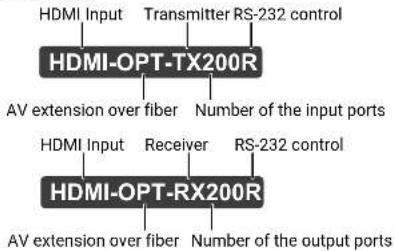
flowchart
graph TD
    A["HDMI-OPT-TX200R"] --> B["AV extension over fiber"]
    A --> C["Number of the input ports"]
    D["HDMI-OPT-RX200R"] --> E["AV extension over fiber"]
    D --> F["Number of the output ports"]
    G["HDMI Input"] --> H["Receiver"]
    I["Transmitter RS-232 control"] --> J["RS-232 control"]
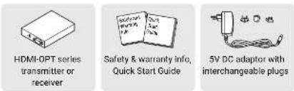
1.2. Box Contents
1.3. Model Comparison
The available models have different features depending on the design. The following table contains the most important differences of the models.
Transmitters
| Video ports | Interface port | Optical output port | ||
| HDMI input | Monitor output (HDMI) | RS-232 | SC multimode output | |
| HDMI-OPT-TX100 | √ | - | - | √ |
| HDMI-OPT-TX100R | √ | - | √ | √ |
| HDMI-OPT-TX200R | √ | √ √ √ | √√ | √ |
Receivers
| Video ports | Interface port | Optical output port | ||
| HDMI output 1 | HDMI output 2 | RS-232 | SC multimode input | |
| HDMI-OPT-RX100 | √ | - | - | √ |
| HDMI-OPT-RX100R | √ | - | √ | √ |
| HDMI-OPT-RX200R | √ | √ √ √ | √√ | √ |


- Introduction HDMI-OPT series - User's Manual 6
1.4. Features of the Device
INFO: Certain features depend on the configuration of the model. For more information about the models see Model Comparison section.

Advanced EDID Management
The user can emulate any EDID on the inputs independently, read out and store any attached monitor's EDID in 100 internal memory locations, upload and download EDID files using Lightware Device Controller software.

Pixel Accurate Reclocking
Each output has a clean, jitter free signal, eliminating signal instability and distortion caused by long cables or connector reflections.

Supports All HDTV Resolutions
720p, 1080i and 1080p etc. with or without HDCP encoding. Signals with up to 225 MHz pixel clock frequency - regardless of the resolution - are passed through.

HDCP Compliant
The HDMI-OPT extenders support HDCP encrypted HDMI signal transmission.

Cross Compatibility
Cross compatibility between all the devices in the product series is ensured thanks to Lightware's attentive design. Any transmitter can be paired with any receiver without restriction. With Lightware's hybrid modular matrix concept, it is even possible to connect an extender box directly to the matrix router using an MX-HDMI-OPT series input or output board (MX-HDMI-OPT-IB or MX-HDMI-OPT-OB).

Front Panel Control on the Transmitter
EDID address selection with two decimal rotary switches and LEARN button are available for Advanced EDID Management. On the HDMI-OPT-TX200R and TX100R the BAUD RATE rotary switch allows selecting the appropriate speed of serial communication.
1.5. Compatible Devices
The HDMI-OPT series devices are compatible with the following:
Transmitters
• HDMI-OPT-RX100, HDMI-OPT-RX100R, HDMI-OPT-RX200R receivers;
• MX-FR modular frames with MX-HDMI-OPT-IB-SC card.
Receivers
- HDMI-OPT-TX100, HDMI-OPT-TX100R, HDMI-OPT-TX200R transmitters;
- MX-FR modular frames with MX-HDMI-OPT-OB-SC card.
1.6. Typical Application
Application examples
- Long distance lossless HDMI or DVI signal transmission
- Ground loop isolation
• Multiroom video and audio control
• Professional AV systems, conference rooms
• High End home cinema - Yacht installations
Standalone Application Diagram

flowchart
graph TD
    A["User Interface RS-22"] --> B["HDMI-OFI-TG20R"]
    B --> C["Local Monitor"]
    C --> D["Projector"]
    D --> E["HDMI-OFI-RG20R"]
    E --> F["Monitor"]
    B --> G["LED"]
    B --> H["LED"]
    B --> I["LED"]
    B --> J["LED"]
    B --> K["LED"]
    B --> L["LED"]
    B --> M["LED"]
    B --> N["LED"]
    B --> O["LED"]
    B --> P["LED"]
    B --> Q["LED"]
    B --> R["LED"]
    B --> S["LED"]
    B --> T["LED"]
    B --> U["LED"]
    B --> V["LED"]
    B --> W["LED"]
    B --> X["LED"]
    B --> Y["LED"]
    B --> Z["LED"]
    B --> AA["LED"]
    B --> AB["LED"]
    B --> AC["LED"]
    B --> AD["LED"]
    B --> AE["LED"]
    B --> AF["LED"]
    B --> AG["LED"]
    B --> AH["LED"]
    B --> AI["LED"]
    B --> AJ["LED"]
    B --> AK["LED"]
    B --> AL["LED"]
    B --> AM["LED"]
    B --> AN["LED"]
    B --> AO["LED"]
    B --> AP["LED"]
    B --> AQ["LED"]
    B --> AR["LED"]
    B --> AS["LED"]
    B --> AT["LED"]
    B --> AU["LED"]
    B --> AV["LED"]
    B --> AW["LED"]
    B --> AX["LED"]
    B --> AY["LED"]
    B --> AZ["LED"]
    B --> BA["LED"]
    B --> BB["LED"]
    B --> BC["LED"]
    B --> BD["LED"]
    B --> BE["LED"]
    B --> BF["LED"]
    B --> BG["LED"]
    B --> BH["LED"]
    B --> BI["LED"]
    B --> BJ["LED"]
    B --> BK["LED"]
    B --> BL["LED"]
    B --> BM["LED"]
    B --> BN["LED"]
    B --> BO["LED"]
    B --> BP["LED"]
    B --> BQ["LED"]
    B --> BR["LED"]
    B --> BS["LED"]
    B --> BT["LED"]
    B --> BU["LED"]
    B --> BV["LED"]
    B --> BW["LED"]
    B --> BX["LED"]
    B --> BY["LED"]
    B --> BZ["LED"]
    B --> CA["LED"]
    B --> CB["LED"]
    B --> CC["LED"]
    B --> CD["LED"]
    B --> CE["LED"]
    B --> CF["LED"]
    B --> CG["LED"]
    B --> CH["LED"]
    B --> CI["LED"]
    B --> CJ["LED"]
    B --> CK["LED"]
    B --> CL["LED"]
    B --> CM["LED"]
    B --> CN["LED"]
    B --> CO["LED"]
    B --> CP["LED"]
    B --> CQ["LED"]
    B --> CR["LED"]
    B --> CS["LED"]
    B --> CT["LED"]
    B --> CU["LED"]
    B --> CV["LED"]
    B --> CW["LED"]
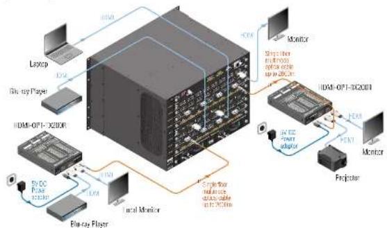
Integrated System Diagram
The chapter is about the installation of the device and connecting to other appliances, presenting also the mounting options and further assembly steps:
MOUNTING OPTIONS
CONNECTING STEPS
2.1. Mounting Options
To mount the extenders Lightware supplies optional accessories for different usage. There are three kinds of mounting kits with similar fixing method:

Under-desk mounting kit

Under-desk double mounting kit

10 high rack shelf
The device has two mounting holes with inner thread on the bottom side; see the bottom view in Mechanical Drawings section. Fasten the device by the screws enclosed to the accessory.
To order mounting accessory kits please contact sales@lightware.com.
WARNING! Always use the supplied screws. Using different (e.g. longer) ones may cause damage to the device.
INFO: The extenders are quarter-rack sized.
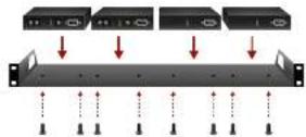
2.1.1. 1U High Rack Shelf
Allows rack mounting for half-rack, quarter-rack and pocket sized units.
1U high rack shelf provides mounting holes for fastening two half-rack or four quarter-rack sized units. Pocket sized devices can also be fastened on the self.
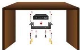
2.1.2. Under-desk Mounting Kit
The UD kit allows pocket sized units to be easily mounted on any flat surface (e.g. furniture).
natural_image
Diagram of a device inside a transparent enclosure with directional arrows indicating movement or force (no text or symbols)INFO: The chipboard screws are not supplied with the mounting kit.
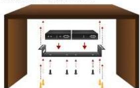
2.1.3. Under-desk Double Mounting Kit
The UD-kit double makes it easy to mount a single device or multiple devices on any flat surface (e.g. furniture).
natural_image
Diagram of a device with arrows indicating movement or force, no text or symbols presentINFO: The chipboard screws are not supplied with the mounting kit.
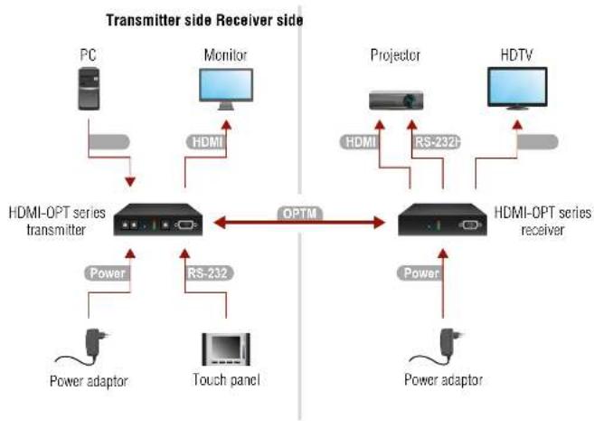
2.2. Connecting Steps
flowchart
graph TD
    PC["PC"] -->|HDMI| HDMI["Monitor"]
    HDMI -->|HDMI| HDMI_OPT["Optimator"]
    HDMI_OPT -->|OPTM| HDTV["HDTV"]
    HDTV -->|HDMI| Projector["Projector"]
    Projector -->|RS-232+| HDMI_OPT
    HDMI_OPT -->|Power| Power_adaptor1["Power adaptor"]
    HDMI_OPT -->|Power| Power_adaptor2["Power adaptor"]
    Power_adaptor1 -->|Power| TouchPanel["Touch panel"]
    Power_adaptor2 -->|Power| TouchPanel
    TouchPanel -->|RS-232| Power_OPT
    Power_OPT -->|Power| HDMI_OPT
Transmitter side
OPTM Connect a multimode (OPTM) fiber cable to the SC fiber output port of the transmitter.
HDMI Connect the source (e.g. a PC) to the HDMI input port of the transmitter by a HDMI cable.
HDMI Optionally connect a local display (e.g. monitor) to the output port.
RS-232 Optionally connect a controller device (e.g. touch panel) to the RS-232 port of the transmitter.
Power Firstly connect the power adaptor to the DC input of the transmitter, then to the AC power socket.
Receiver side
OPTM Connect a multimode (OPTM) fiber cable to the SC fiber input port of the receiver.
HDMI Connect the sink (e.g. a projector) to the HDMI output port of the receiver by a HDMI cable.
HDMI Optionally connect a controlled device (e.g. projector) to the RS-232 port of the receiver. ^4
RS-232 Optionally connect a secondary display (e.g. HDTV) to the HDMI OUT 2 port.
Power Firstly connect the power adaptor to the DC input of the receiver, then to the AC power socket.
1 Only in the case of HDMI-OPT-TX200R model.
^2 Only in the case of HDMI-OPT-TX100R/TX200R models.
* Only in the case of HDMI-OPT-RX100R/RX200R models.
^1 Only in the case of HDMI-OPT-RX200R model.
WARNING! Please do not look directly into the SC fiber optical connector if the cable is connected to the transmitter only and the laser is active.
INFO: Powering the devices on is recommended to do as the final step during the installation.


- Installation HDMI-OPT series - User's Manual 9
2.2.1. Baud Rate Settings
HDMI-OPT units use some of the standard timings for the RS-232 pass-through. To work the bidirectional serial communication well between serial ending devices users must choose the proper baud rate on the transmitter units. Please read the serial devices' user's manual to find the appropriate baud rates. The best one is both devices' most common value.
If the communication speed ability of a serial device is unknown use the lowest (#0: 9600) value.
To use Lightware Device Controller or Lightware Bootloader software select the #9 position (SW control).
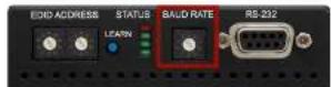
Baud Rate Rotary on the HDMI-OPT-TX200R model
| Rotary switch position | BAUD rate |
| 0 9600 | |
| 1 14400 | |
| 2 19200 | |
| 3 38400 | |
| 4 57600 | |
| 5 Not used | |
| 6 Not used | |
| 7 Not used | |
| 8 Not used | |
| 9 SW control |
Baud Rate Rotary Switch Values
3
Product Overview
The following sections are about the physical structure of the device, input/output ports and connectors:
HDMI-OPT SERIES RECEIVERS
HDMI-OPT SERIES TRANSMITTERS
▶ ELECTRICAL CONNECTIONS
▶ OPTICAL EXTENDER CONCEPT
HDMI OUTPUT SETTINGS
RS-232 SIGNAL TRANSMISSION
3.1. HDMI-OPT Series Receivers
HDMI-OPT-RX100 - Front and Rear View
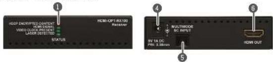
text_image
LOOP ENCRISPED CONTENT HOME CHANNEL VIDEO CLOUD FLOW Laser detected STATUS HOME-OPT-RESUS Recovery MULTIPOCK DC INPUT 5V MAX DC PWR 2.00mm HOME OUTHDMI-OPT-RX100R - Front and Rear View
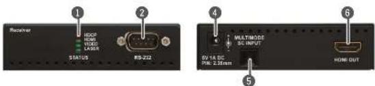
text_image
Receiver 1 1000 1000 1000 LARGE STATUS RS-232 4 MULTIMODE 3D INPUT 5 BY 14 DC 34V 2.38mm HONE OUT 6HDMI-OPT-RX200R - Front and Rear View
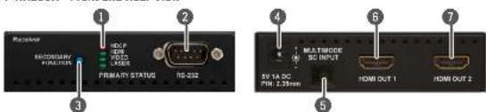
text_image
Receiver EASY POWER FUNCTION Laser 1 2 3 4 5 6 7 PRIMARY STATUS ND-032 MULTIODE DC INPUT SVA TA DC PIN 2.33mm HOM OUT 1 HOM OUT 21 Status LEDs The LEDs give feedback about the state of units and video signal. For more information see The Legend of Status LEDs section.
2 RS-232 port 9-pole D-sub male connector. Connect a serial cable between the receiver and the serial device. For more details see Serial Management section.
3 Function button Toggles the LED functions between PRIMARY (SOLID) and SECONDARY (BLINKING). For more information see Primary and Secondary Modes section.
4 5V DC input Connect the output of the supplied 5V DC power adaptor.
5 SC Fiber Input Connect a multimode single fiber optical cable between the extenders.
6 HDMI output Connect one HDMI cable between the receiver and the sink device.
7 HDMI output 2 Connect one HDMI cable between the receiver and the secondary sink device.


- Product Overview HDMI-OPT series - User's Manual 11
3.2. HDMI-OPT Series Transmitters
HDMI-OPT-TX100 - Front and Rear View
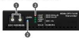
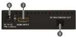
HDMI-OPT-TX100R - Front and Rear View
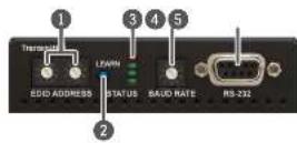
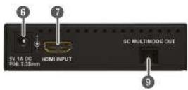
HDMI-OPT-TX200R - Front and Rear View
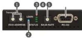
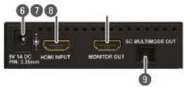
1 EDID rotary switches The rotary switches select one of 99 addresses. EDID memories #1..#50 contain factory presets and #51..#99 are user programmable. For more information see EDID Operations section.
2 LEARN button Toggles the LED functions between PRIMARY (SOLID) and SECONDARY (BLINKING). For more information see Primary and Secondary Modes section.
3 Status LEDs The LEDs give feedback about the state of units and video signal. For more information about names and meanings of the Status LEDs see The Legend of Status LEDs section.
4 Baud rate rotary The rotary switch selects one of 5 speeds of the serial communication (#0..#4) or the Software Control mode (#9).
5 RS-232 port 9-pole D-sub female connector. Connect a serial cable between the transmitter and the desired serial device. For more details see Serial Management section.
5V DC input Connect the output of the supplied 5V DC power adaptor.
7 HDMI input Connect one HDMI cable between the HDMI source and the transmitter.
6 MONITOR output Connect one HDMI cable between the local display device and the transmitter.
9 SC Fiber output Connect a multimode single fiber optical cable between the transmitter and the receiver.


- Product Overview HDMI-OPT series - User's Manual 12
3.3. Electrical Connections
3.3.1. DC 5V Connection
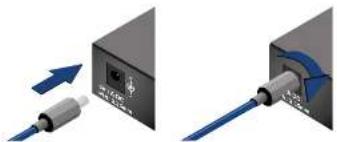
The device has locking DC connector to establish robust and safe power connection. After plugging it in, turn the plug clockwise as you can see in the picture below.
natural_image
Two diagrams showing a device with a cable inserted into a black box and its internal structure being inserted (no text or symbols present)Locking DC connector
Do not forget to turn the connector counterclockwise before trying to disconnect the power adaptor.
WARNING!
Always use the supplied 5V power adaptor. Warranty is void if damage occurs due to use of a different power source.
3.3.2. HDMI Inputs and Outputs
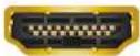
HDMI-OPT units provide standard 19 pole HDMI connectors for inputs and outputs. Always use high quality HDMI cable for connecting sources and displays.
3.3.3. SC Fiber Input and Output
HDMI-OPT series transmitters and receivers provide multimode SC fiber optical input and output connectors.
Maximum fiber cable distances can be found in Maximum Extension Distances section.

3.3.4. RS-232 Connectors
HDMI-OPT-TX200R/TX100R and HDMI-TP-RX200R/RX100R have standard 9 pin female and male D-sub miniature receptacle.

D-sub 9-pin female (DE9F) D-sub 9-pin male (DE9M)
| Pin nr. RS-232 straight pin-out |
| 1 Not connected |
| 2 TX data transmit (out) |
| 3 RX data receive (in) |
| 4 DTR (Internally connected to Pin 6) |
| 5 GND signal ground (shield) |
| 6 DSR (Internally connected to Pin 4) |
| 7 RTS (Internally connected to Pin 8) |
| 8 CTS (Internally connected to Pin 7) |
| 9 Not connected |
| Pin nr. RS-232 cross pin-out |
| 1 Not connected |
| 2 RX data receive (in) |
| 3 TX data transmit (out) |
| 4 DTR (Internally connected to Pin 6) |
| 5 GND signal ground (shield) |
| 6 DSR (Internally connected to Pin 4) |
| 7 RTS (Internally connected to Pin 8) |
| 8 CTS (Internally connected to Pin 7) |
| 9 Not connected |


- Product Overview HDMI-OPT series - User's Manual 13
3.4. Optical Extender Concept
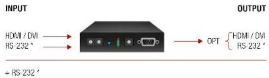
HDMI-OPT series transmitters and receivers are a digital audio/video signal extenders with RS-232 signal transmission. The transmitter receives HDMI video with embedded digital audio signal and transmits them over a single multimode fiber optical cable. Besides of the A/V signal the transmitter is able send RS-232 signal as well over the same optical line. The receiver accepts the optical signal and transmits to the sink device. In the case of RX200R model two display devices can be attached to the receiver. The receiver is also able to transmit the RS-232 commands to the controlled device.
Summary of Interfaces - Transmitters
text_image
INPUT HDMI / DVI RS-232 * → OPT { HDMI / DVI RS-232 * + RS-232 ** Only TX100R and TX200R models.
Summary of Interfaces - Receivers
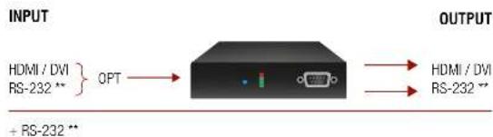
text_image
INPUT HDMI / DVI RS-232 ** } OPT → + RS-232 ** OUTPUT HDMI / DVI RS-232 **** Only RX100R and RX200R models.
3.5. HDMI Output Settings
HDMI-OPT unit is able to recognize the type of the incoming video signal and set automatically the proper one to the output.
Auto output mode function determines the output signal (DVI or HDMI) by the source, emulated EDID and the connected device's EDID on the local MONITOR OUT. Table below contains the possible cases of the signals' type.
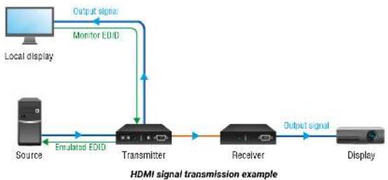
flowchart
graph LR
    A["Local display"] -->|Output signal| B["Monitor EDID"]
    B --> C["Transmitter"]
    C --> D["Receiver"]
    D -->|Output signal| E["Display"]
    F["Source"] -->|Emulated EDID| C
| Source Emulated EDID Local monitor EDID Output signal type | |||
| DVI DVI or HDMI DVI or HDMI DVI | |||
| HDMI DVI | DVI or HDMI DVI | ||
| HDMI | HDMI | DVI | DVI |
| HDMI HDMI | HDMI | HDMI | |
In the highlighted row (HDMI source, HDMI emulated EDID but only DVI capable monitor) colorspace converting problems can appear. HDMI standard supports RGB and YUV (also known YCbCr) colorspaces but DVI supports only the RGB. HDMI-OPT units do not support colorspace conversion between HDMI YUV and RGB. If the source sends HDMI signal with YUV colorspace settings and the sink device can work only in RGB mode the color components can be mismatched during the process. Monitor recognize Y component as R, Cb as G and Cr as B. It causes wrong colors and the embedded audio frame of HDMI will be lost.
In most of the HDMI sources the colorspace can be set manually by the user. If not, an EDID must be used which does not support YUV colorspace. This kind of EDID can be made easily with Lightware Device Controller software. For the detailed instructions see Creating an EDID section.
INFO: EDIDs without CEA extension effect RGB colorspace but these EDIDs do not support HDMI embedded audio.


- Product Overview HDMI-OPT series - User's Manual 14
3.6. RS-232 Signal Transmission
ATTENTION! Only HDMI-OPT-TX100R and TX200R transmitters and HDMI-OPT-RX100R and RX200R receivers are built with RS-232 ports.
Technical Background
Serial data communication can be established via the local RS-232 port (D-SUB connector) and can be transmitted via the optical line up to 2600 meter far. The RS-232 commands are received by the receiver which can transmit them to the controllable device (e.g. a projector) via the local D SUB port. This method makes the extenders suitable to control any third-party device with RS-232 commands.
RS-232 Signal Transmission - Example
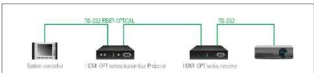
flowchart
graph LR
    A["System controller"] --> B["RS-252 FEER1 OPTICAL"]
    C["HDMI OPT series transceiver Projector"] --> B
    D["HDMI OPT series receiver"] --> B
    E[" "] --> F["RS-252"]
The Concept
The System controller sends messages over the RS-232 port of the Transmitter. The Transmitter sends the messages over the optical line without any modification toward the Receiver. The Receiver sends the messages to the Projector which is recognized and executed them.
INFO: Always check the baud rate of the sender and receiver devices. Do not forget to set up the correct baud rate value on the rotary switch located on the transmitter's front panel.


- Operation HDMI-OPT series - User's Manual 15

Operation
This chapter is about the powering and operating of the device describing the functions which are available by the front/rear controls:
FRONT PANEL LEDS
▶ EDID OPERATIONS
4.1. Front Panel LEDs
To save space and simplify readability HDMI-OPT unit uses only four LEDs to inform users about the connections and the video signals. Because of the low numbers of LEDs two modes and several functions are used for display information.
4.1.1. Primary and Secondary Modes
Two modes are available. In PRIMARY (SOLID) mode LEDs light continuously and give information about the incoming connection and video signal. In SECONDARY (BLINKING) mode LEDs blink and give information about EDID management and outgoing connections. Push down and release the LEARN button to change between PRIMARY and SECONDARY mode.
INFO: LED modes were made for only showing information and do not affect applying changes with front panel's controls. The user can choose or learn EDID in either LED modes, even though the actual state is not visible.
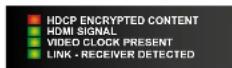
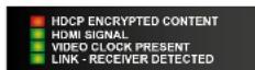
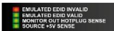
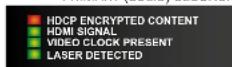
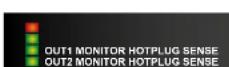
4.1.2. The Legend of Status LEDs
The legend shows the LEDs' color and short description about the meaning can also be found on the top of the devices.
HDMI-OPT-TX100 / HDMI-OPT-TX100R
PRIMARY (SOLID) SECONDARY (BLINKING)
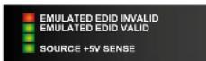
HDMI-OPT-TX200R
PRIMARY (SOLID) SECONDARY (BLINKING)
HDMI-OPT-RX100 / HDMI-OPT-RX100R
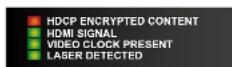
HDMI-OPT-RX200R
PRIMARY (SOLID) SECONDARY (BLINKING)
4.1.3. Transmitter LED Modes
| Status LED | LED mode | Description TX | TX100 TX100R TX200R | |
| PRIMARY (SOLID) MODE | HDCP encrypted content | Indicates if the source signal is HDCP encrypted. | ||
| HDMI signal | Indicates the type of the video signal. In case of existing HDMI signal the LED lights continuously. In case of existing DVI signal the LED is off and the Video Clock present LED is lights continuously. | |||
| Video clock present | Indicates if a valid HDMI clock signal is present on the transmitters' HDMI input or the receivers' SC multimode in connector. | |||
| Link - Receiver detected | Indicates if a powered receiver (e.g. RX200R) is connected to the transmitter and they can communicate over the fiber optical cable. When no receiver is connected, and the transmitter powered, the LED is blinking by 1Hz frequency. | |||
| SECONDARY (BLINKING) MODE | Emulated EDID invalid | The LED lights red if the selected EDID is invalid or empty memory selected. | ||
| After applying a Hot Plug signal(s) to the OUTPUT(s), this LED indicates that the unit is trying to read the EDID from the connected display device, but the EDID is invalid or missing. | ||||
| After pressing the LEARN button, this LED's blinking indicates if the learn process was unsuccessful. | ||||
| Emulated EDID valid | The LED lights green if the selected EDID is valid. | |||
| After applying a Hot Plug signal(s) to the OUTPUT(s), this LED indicates that the unit is reading the EDID from the connected display device and the EDID is valid. | ||||
| After pressing the LEARN button, this LED's blinking indicates if the learn process was successful. | ||||
| Monitor out hotplug sense | - | - | ||
| Source +5V sense | Indicates if a powered display device (or matrix switcher, repeater, etc.) is connected to the HDMI output connector and sends a valid hotplug signal on pin 19 through the HDMI cable. | |||
4.1.4. Receiver LED Modes
| Status LED | LED mode | Description RX100 RX100R RX200R | ||
| PRIMARY (SOLID) MODE | HDCP encrypted content | Indicates if the source signal is HDCP encrypted. | ||
| HDMI signal | Indicates the type of the video signal. In case of existing HDMI signal the LED lights continuously. In case of existing DVI signal the LED is off and the Video Clock present LED is lights continuously. | |||
| Video clock present | Indicates if a valid HDMI clock signal is present on the transmitters' HDMI input or the receivers' SC multimode in connector. | |||
| Laser detected | Indicates if a powered transmitter (e.g. TX200R) is connected to the receiver and they can communicate over the fiber optical cable. | |||
| SECONDARY (BLINKING) MODE | Monitor out hotplug sense OUT1 / OUT2 | - | - | |
4.2. EDID Operations
ATTENTION! EDID settings are available in the HDMI-OPT series transmitters only, the receivers are transparent in the video signal point of view.
4.2.1. About EDID Memory
The EDID memory is non-volatile and can store 99 EDIDs. The memory structure is as follows:
| Description | Rotary switch state | Memory bank number in LDC |
| Factory Preset EDID list #01 - #50 F01 - F50 | ||
| User programmable slots #51 - #98 U1 - U48 | ||
| Last attached monitor's EDID (local monitor) | #00 D01 |
INFO: HDMI-OPT series transmitters can handle both 128 Byte EDID and 256 Byte extended EDID structures.
INFO: The attached monitor's EDID is stored automatically, until a new monitor is attached to the local monitor output. In the case of powering the unit off, the last attached monitor's EDID remains in non-volatile memory.
INFO: The transmitters always learn the stored last attached monitor's EDID into the user programmable EDID memory.
Factory Preset EDIDs
The factory EDIDs (F1-F50) are factory preprogrammed and cannot be modified. These are the most common resolutions. They are specially provided to force graphic cards to output only the exact pixel resolution and refresh rate.
Universal HDMI (F49) allows multiple resolutions including all common VESA defined resolutions. The use of universal EDID is recommended for fast and easy system setup.
You can find all the factory preset EDID in Factory EDID List section.
INFO: The factory EDIDs (#1..#50 inclusive) preprogrammed and cannot be modified. These are the most commonly used resolutions.
4.2.2. Switching EDID
The user can select an EDID to emulate on the input, this is called EDID routing. There are two types of the emulation: static and dynamic.
- Static EDID emulation happens, when an EDID from the Factory or User EDID list is routed to an input.
- Dynamic EDID emulation occurs, when an attached monitor's EDID is routed to an input. In this case the emulated EDID changes automatically, if a new monitor is attached to the output, by simply copying the data from the monitor.
Step 1. Use a screwdriver to change the memory address on the rotary switches on the front side of the transmitter. The left switch sets the tens value, the right switch gives the ones value of the EDID.
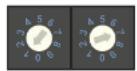
Location #17 is selected by the rotary switches
ATTENTION! Avoid the use of keys, coins, knives and other sharp objects switching the rotary switches.
Step 2. After either one of the rotary switches has been rotated the unit waits approximately two seconds before the selected EDID becomes active.
Step 3. Check the status of the device on the Status LEDs. See the The Legend of Status LEDs.
The address #00 has a special function in the case of HDMI-OPT-TX200R. If a monitor is connected to the MONITOR OUT, then its EDID is copied to the HDMI INPUT connector. If no monitor is connected to the MONITOR OUT then the EDID transmitted to the INPUT connector is the EDID of the last connected monitor.
4.2.3. Learning EDID
The factory preset EDIDs cannot be changed by the user. Only addresses from #51 to #98 are user programmable.
Step 1. After connecting the sink device to HDMI OUTPUT, use a screwdriver to select a user programmable memory address on the rotary switches. If the Status LED is illuminated red, then the memory slot is empty and ready to be programmed. If it is green, the memory was already used before, but still available for reprogramming.
ATTENTION! Avoid the use of keys, coins, knives and other sharp objects switching the rotary switches.
Step 2. Push the LEARN button on the front side of transmitter and hold it down for approximately three seconds. If the teaching is successful, the Status LED blinks four times green, if the teaching is unsuccessful, the Status LED blinks four times red.
Step 3. The normal function of the LED is in effect.
INFO: The last attached monitor's EDIDs are stored automatically, until a new monitor is attached to the MONITOR OUT. In the case of powering the unit off, the last attached monitor's EDID remains in non-volatile memory.
INFO: If the selected user memory is not empty, the new EDID will overwrite the previously stored EDID.
TIPS AND TRICKS: HDMI-OPT-TX200R can learn EDID with LEARN button from local HDMI output called MONITOR OUT.
4.2.4. Deleting EDID
EDID cannot be deleted by the controls on the front panel, only by Lightware Device Controller software. See more information in section EDID Menu.
5
Software Control - Using Lightware Device Controller
The device can be controlled by a computer through the RS-232 port using Lightware Device Controller (LDC). The software can be installed on a Windows PC or MacOS. The application and the User's manual can be downloaded from www.lightware.com. The Windows and the Mac versions have the same look and functionality.
INSTALL AND UPGRADE
▶ ESTABLISHING THE CONNECTION
I/O PARAMETERS MENU
▶ EDID MENU
▶ SETTINGS MENU
▶ TERMINAL WINDOW
5.1. Install and Upgrade
Installation for Windows OS
Step 1. Run the installer. If the User Account Control drops a pop-up message click Yes.
Step 2. During the installation you will be prompted to select the type of the installation: normal and the snapshot install:
| Normal install Snapshot install | |
| Available for Windows and MacOS | Available for Windows |
| The installer can update only this instance | Cannot be updated |
| Only one updateable instance can exist for all users | More than one different version can be installed for all users |
Comparison of installation types
ATTENTION! Using the Normal install as the default choice is highly recommended.
Installation for MacOS X
Mount the DMG file with double clicking on it and drag the LDC icon over the Applications icon to copy the program into the Applications folder. If you want to copy the LDC into another location just drag the icon over the desired folder.
Upgrading of LDC
Step 1. Run the application.
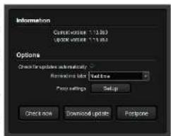
The Device Discovery window appears automatically and the program checks the available updates on Lightware's website and opens the update window if the LDC found updates.
The current and the update version number can be seen at the top of the window and they are shown in this window even with the snapshot install.
text_image
Information Custom version: 11.0.00 UP/UP version: 11.0.00 Options Check for updates automatically Refresh rate: Default Prior settings Setup Check now Download update PostponeThe Update window can also be opened by clicking the About icon and the Update button.
Set the desired update setting in the Options section.
- If you do not want to check for the updates automatically, uncheck the circle, which contains the green tick.
- If you want to postpone the update, a reminder can be set with different delays from the drop down list.
If the proxy settings traverse the update process, set the proper values then click the OK button.
Step 2. Click the Download update button to start the upgrading.
The updates can be checked manually by clicking the Check now button.
INFO: After the installation, the Windows and the Mac application has the same look and functionality.
5.2. Establishing the Connection
Step 1. Connect the device to a computer via RS-232.
Step 2. Run the controller software; device discovery window appears automatically.
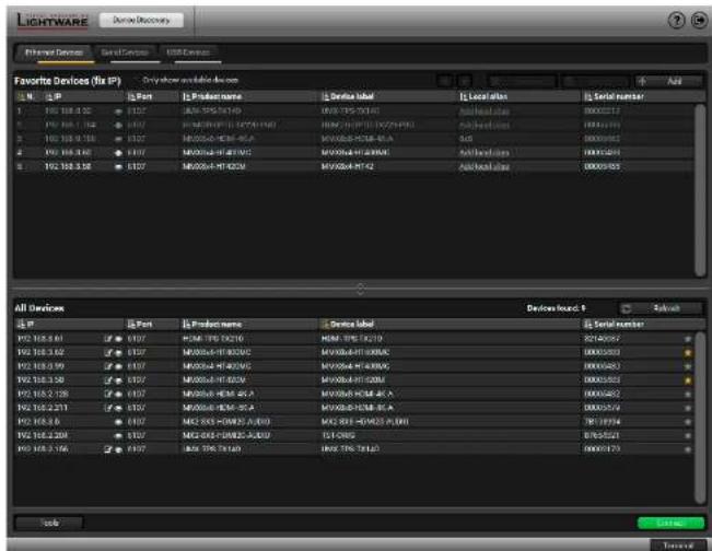
text_image
Lightware Device Discovery Ethernet Devices Serial Devices USB Devices Favorite Devices (Fix IP) Only show available devices N: 2 IP 1 F01 368.450 2 F01 368.451 3 F01 368.452 4 F01 368.453 5 F01 368.454 6 F01 368.455 7 F01 368.456 8 F01 368.457 9 F01 368.458 10 F01 368.459 11 F01 368.460 12 F01 368.461 13 F01 368.462 14 F01 368.463 15 F01 368.464 16 F01 368.465 17 F01 368.466 18 F01 368.467 19 F01 368.468 20 F01 368.469 21 F01 368.470 22 F01 368.471 23 F01 368.472 24 F01 368.473 25 F01 368.474 26 F01 368.475 27 F01 368.476 28 F01 368.477 29 F01 368.478 30 F01 368.479 31 F01 368.480 32 F01 368.481 33 F01 368.482 34 F01 368.483 35 F01 368.484 36 F01 368.485 37 F01 368.486 38 F01 368.487 39 F01 368.488 40 F01 368.489 41 F01 368.490 42 F01 368.491 43 F01 368.492 44 F01 368.493 45 F01 368.494 46 F01 368.495 47 F01 368.496 48 F01 368.497 49 F01 368.498 50 F01 368.499 51 F01 370.000 52 F01 370.001 53 F01 370.002 54 F01 370.003 55 F01 370.004 56 F01 370.005 57 F01 370.006 58 F01 370.007 59 F01 370.008 60 F01 370.009 61 F01 370.010 62 F01 370.011 63 F01 370.012 64 F01 370.013 65 F01 370.014 66 F01 370.015 67 F01 370.016 68 F01 370.017 69 F01 370.018 70 F01 370.019 71 F01 370.020 72 F01 370.021 73 F01 370.022 74 F01 370.023 75 F01 370.024 76 F01 370.025 77 F01 370.026 78 F01 370.027 79 F01 370.028 80 F01 370.029 All Devices: Device Board: Select: Serial Number: F/XP: B/XP: B/XP: B/XP: B/XP: B/XP: B/XP: B/XP: B/XP: B/XP: B/XP: B/XP: B/XP: B/XP: B/XP: B/XP: B/XP: B/XP: B/XP: B/XP: B/XP: B/XP: B/XP: B/XP: B/XP: B/XP: A/B/C/A/B/C/A/B/C/A/B/C/A/B/C/A/B/C/A/B/C/A/B/C/A/B/C/A/B/C/A/B/C/A/B/C/A/B/C/A/B/C/A/B/C/A/B/C/A/B/C/A/B/C/A/B/C/A/B/C/A/B/C/A/B/C/A/B/C/A/B/C/A/B/C/A/B/C/A/B/C/A/B/C/A/B/C/A/B/C/A/B/C/A/B/C/A/B/C/A/B/C/A /B/C/A/B/C/A/B/C/A/B/C/A/B/C/A/B/C/A/B/C/A/B/C/A/B/C/A/B/C/A/B/C/A/B/C/A/B/C/A/B/C/A/B/C/A/B/C/A/B/C/A/B/C/A/B/C/A/B/C/A/B/C/A/B/C/A/B/C/A/B/C/A/B/C/A/B/C/A/B/C/A/B/C/A/B/C/A/B/C/A/B/C/A/B/C/A/B/C/A/B/G/S/S/S/S/S/S/S/S/S/S/S/S/S/S/S/S/S/S/S/S/S/S/S/S/S/S/S/S/S/S/S/S/S/S/S/S/S/S/S/S/S/S/S/S/S/S/S/S/S/S/S/S/S/S/S/S/S/S/S/S/S/S/S/S/S/S/S/S/S/S/S/S/S/S/S/S/S/S/S/S/S/S/S/S/S/S/S/S/S/S/S/S/S/S/S/S/S/S/S/S/Tb/Tb/Tb/Tb/Tb/Tb/Tb/Tb/Tb/Tb/Tb/Tb/Tb/Tb/Tb/Tb/Tb/Tb/Tb/Tb/Tb/Tb/Tb/Tb/Tb/Tb/Tb/Tb/Tb/Tb/Tb/Tb/Tb/Tb/Tb/Tb/Tb/Tb/Tb/Tb/Tb/Tb/Tb/Tb/Tb/Tb/Tb/Tb/Tb/Tb/TaT/bTb/Tb/Tb/Tb/Tb/Tb/Tb/Tb/Tb/Tb/Tb/Tb/Tb/Tb/Tb/Tb/Tb/Tb/Tb/Tb/Tb/Tb/Tb/Tb/Tb/Tb/Tb/Tb/Tb/Tb/Tb/Tb/Tb/Tb/Tb/Tb/Tb/Tb/Tb/Tb/Tb/Tb/Tb/Tb/Tb/Tb/Tb/Tb/Tb/Tb /Bc /Bc /Bc /Bc /Bc /Bc /Bc /Bc /Bc /Bc /Bc /Bc /Bc /Bc /Bc /Bc /Bc /Bc /Bc /Bc /Bc /Bc /Bc /Bc /Bc /Bc /Bc /Bc /Bc /Bc /Bc /Bc /Bc /Bc : bT bT bT bT bT bT bT bT bT bT bT bT bT bT bT bT bT bT bT bT bT bT bT bT bT bT bT bT bT bT bT bT bT bT bT bT bT bT bT bT bT bT bT bT bT bT bT bT bT bT bI T bI T bI T bI T bI T bI T bI T bI T bI T bI T bI T bI T bI T bI T bI T bI T bI T bI T bI T bI T bI T bI T bI T bI T bI T bI T bI T bI T bI T bI T bI T bI T bI T bI T tB tB tB tB tB tB tB tB tB tB tB tB tB tB tB tB tB tB tB tB tB tB tB tB tB tB tB tB tB tB tB tB tB tB tB tB tB tB tB tB tB tB tB tB tB tB tB tB tB tB tA B C A B C A B C A B C A B C A B C A B C A B C A B C A B C A B C A B C A B C A B C A B C A B C A B C A B C A B C A B C A B C A B C A B C A B C A B C A B C A B C A B C A B C A B C A B C A B C A B C A B C ADevice Discovery Window in LDC
Step 3. Select the Serial Devices tab. Click on the Query button to next to the desired serial port to display the device's name and serial number. Double click on the name of the device or select it and click on the Connect button.
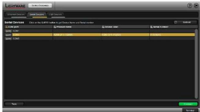
text_image
LIGHTWARE Device & Discovery Interrupt Devices Quick Devices SSL Devices Serial Devices Click on the QUERY button to get Customer Name and Serial Number Store name Product name Product user Serial number B001 - COM B002 - COM B003 - COM B004 - COM B005 - COM B006 - COM B007 - COM B008 - COM B009 - COM B010 - COM B011 - COM B012 - COM B013 - COM B014 - COM B015 - COM B016 - COM B017 - COM B018 - COM B019 - COM B020 - COM B021 - COM B022 - COM B023 - COM B024 - COM B025 - COM B026 - COM B027 - COM B028 - COM B029 - COM B030 - COM B031 - COM B032 - COM B033 - COM B034 - COM B035 - COM B036 - COM B037 - COM B038 - COM B039 - COM B040 - COM B041 - COM B042 - COM B043 - COM B044 - COM B045 - COM B046 - COM B047 - COM B048 - COM B049 - COM B050 - COM B051 - COM B052 - COM B053 - COM B054 - COM B055 - COM B056 - COM B057 - COM B058 - COM B059 - COM B060 - COM B061 - COM B062 - COM B063 - COM B064 - COM B065 - COM B066 - COM B067 - COM B068 - COM B069 - COM B070 - COM B071 - COM B072 - COM B073 - COM B074 - COM B075 - COM B076 - COM B077 - COM B078 - COM B079 - COM B080 - COM B081 - COM B082 - COM B083 - COM B084 - COM B085 - COM B086 - COM B087 - COM B088 - COM B089 - COM B090 - COM B091 - COM B092 - COM B093 - COM B094 - COM B095 - COM B096 - COM B097 - COM B098 - COM B099 - COMThe Serial Devices Tab in Device Discovery Window
5.3. I/O Parameters Menu
The menu displays the current state of the device. The input port of the device is on the right top, the output ports are on the right bottom side. The properties of input port is displayed as default.
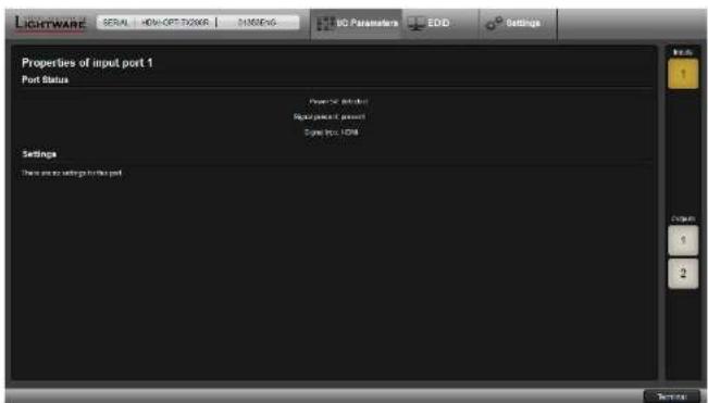
text_image
LIGHTWARE SERIAL HOME OPT ORDER MINDING NO Parameters EDD Settings Properties of input port 1 Port Status Power PC Retected Signal packet port Signal type: HDMI Settings There are no settings for this portI/O Parameters menu
5.4. EDID Menu
Advanced EDID Management can be accessed by selecting the EDID menu. There are two panels: left one contains Source EDIDs, right one contains Destination places where the EDIDs can be emulated or copied.
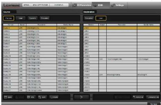
text_image
LIGHTWARE BSSA | ICM-017-2006 | EDD 40 Parameters | EDD | Settings Source Destination Function User Dynamic Escalator Encircled Load Name Label Settings Modulation Driver 1 Driver 2 Driver 3 Driver Name Driver 1 Driver 2 Driver 3 Driver Name Driver 2 Driver 2 Driver 3 Driver Name Driver 3 Driver 2 Driver 3 Driver Name Driver 4 Driver 2 Driver 3 Driver Name Driver 5 Driver 2 Driver 3 Driver Name Driver 6 Driver 2 Driver 3 Driver Name Driver 7 Driver 2 Driver 3 Driver Name Driver 8 Driver 2 Driver 3 Driver Name Driver 9 Driver 2 Driver 3 Driver Name Driver 10 Driver 2 Driver 3 Driver Name Driver 11 Driver 2 Driver 3 Driver Name Driver 12 Driver 2 Driver 3 Driver Name Driver 13 Driver 2 Driver 3 Driver Name Driver 14 Driver 2 Driver 3 Driver Name Driver 15 Driver 2 Driver 3 Driver Name Driver 16 Driver 2 Driver 3 Driver Name Driver 17 Driver 2 Driver 3 Driver Name Driver 18 Driver 2 Driver 3 Driver Name Driver 19 Driver 2 Driver 3 Driver Name Driver 20 Driver 2 Driver 3 Driver Name Driver 21 Driver 2 Driver 3 Driver Name Driver 22 Driver 2 Driver 3 Driver Name Driver 23 Driver 2 Driver 3 Driver Name Driver 24 Driver 2 Driver 3 Driver Name Driver 25 Driver 2 Driver 3 Driver Name Driver 26 Driver 2 Driver 3 Driver Name Driver 27 Driver 2 Driver 3 Driver Name Driver 28 Driver 2 Driver 3 Driver Name Driver 29 Driver 2 Driver 3 Driver Name Driver 30 Driver 2 Driver 3 Driver Name Driver 31 Driver 2 Driver 3 Driver Name Driver 32 Driver 2 Driver 3 Driver Name Driver 33 Driver 2 Driver 3 Driver Name Driver 34 Driver 2 Driver 3 Driver Name Driver 35 Driver 2 Driver 3 Driver Name Driver 36 Driver 2 Driver 3 Driver Name Driver 37 Driver 2 Driver 3 Driver Name Driver 38 Driver 2 Driver 3 Driver Name Driver 39 Driver 2 Driver 3 Driver Name Driver 40 Driver 2 Driver 3 Driver Name Driver 41 Driver 2 Driver 3 Driver Name Driver 42 Driver 2 Driver 3 Driver Name Driver 43 Driver 2 Driver 3 Driver Name Driver 44 Driver 2 Driver 3 Driver Name Driver 45 Driver 2 Driver 3 Driver Name Driver 46 Driver 2 Driver 3 Driver Name Driver 47 Driver 2 Driver 3 Driver Name Driver 48 Driver 2 Driver 3 Driver Name Driver 49 Driver 2 Driver 3 Driver Name Driver 50 Driver 2 Driver 3 Driver Name Driver 51 Driver 2 Driver 3 Driver Name Driver 52 Driver 2 Driver 3 Driver Name Driver 53 Driver 2 Driver 3 Driver Name Driver 54 Driver 2 Driver 3 Driver Name Driver 55 Driver 2 Driver 3 Driver Name Driver 56 Driver 2 Driver 3 Driver Name Driver 57 Driver 2 Driver 3 Driver Name Driver 58 Driver 2 Driver 3 Driver Name Driver 59 Driver 2 Driver 3 Driver Name Driver.0000000000000000000000000000000000000000000000000000000000000000000000000000000000000000000000000000EDID Menu
Control Buttons

Save
Exporting an EDID (save to a file)


Upload
Importing an EDID (load from a file)

Delete selected

Info
Display EDID Summary window

Select All

Edit
Opening Advanced EDID Editor with the selected EDID

Deselect All

Create
Opening Easy EDID Creator
Executing EDID emulation or copying (Transfer button) Deleting EDID (from User memory)
Selecting all memory places in the right panel
Selecting none of the memory places in the right panel


- Software Control - Using Lightware Device Controller
HDMI-OPT series - User's Manual
5.4.1. Sources and Destinations
The EDID memory consists of four parts:
• Factory EDID list shows the pre-programmed EDIDs (F1-F50).
- Dynamic EDID list shows the display device connected to the device's outputs. The unit stores the last display devices' EDID on either output, so there is an EDID shown even if there is no display device attached to the output port at the moment.
- User memory locations can be used to save custom EDIDs. (U1 - U48)
- Emulated EDID list shows the currently emulated EDID for the inputs. The source column displays the memory location that the current EDID was routed from.
The source reads the EDID from the Emulated EDID memory on the INPUT port. Any EDID from any of the User/Factory/Dynamic EDID lists can be copied to the user memory.
There are two types of emulation: static and dynamic.
- Static EDID emulation: an EDID from the Factory or User EDID list is selected. Thus, the Emulated EDID remains the same until the user emulates another EDID.
- Dynamic EDID emulation: it can be enabled by selecting D1 EDID memory. The attached monitor's EDID is copied to the input; if a new monitor is attached to the output, the emulated EDID changes automatically.
5.4.2. EDID Operations
Learning an EDID
The process is the same as changing the emulated EDID; the only difference is the Destination panel: press the User button. Thus, one or more EDIDs can be copied into the user memory either from the factory memory or from a connected sink device (Dynamic).

Exporting an EDID
Source EDID can be downloaded as a file (*.bin, *.dat or *.edid) to the computer.
Step 1. Select the desired EDID from the Source panel (line will be highlighted with yellow).
Step 2. Press the Save button to open the dialog box and save the file to the computer.
Importing an EDID
Previously saved EDID (*.bin, *.dat or *.edid file) can be uploaded to the user memory:
Step 1. Press the User button on the top of the Source panel and select a memory slot.
Step 2. Press the Upload button below the Source panel.
Step 3. Browse the file in the opening window then press the Open button. Browsed EDID is imported into the selected User memory.

ATTENTION! The imported EDID overwrites the selected memory place even if it is not empty.
Deleting EDID(s)
The EDID(s) from User memory can be deleted as follows:
Step 1. Press User button on the top of the Destination panel.
Step 2. Select the desired memory slot(s); one or more can be selected (Select All and Select None buttons can be used). The EDID(s) will be highlighted with yellow.
Step 3. Press the Delete selected button to delete the EDID(s).
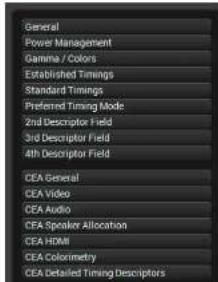
5.4.3. EDID Summary Window
Select an EDID from Source panel and press Info button to display EDID summary.

text_image
General Power Management Gamma / Colors Established Timings Standard Timings Preferred Timing Mode 2nd Descriptor Field 3rd Descriptor Field 4th Descriptor Field CEA General CEA Video CEA Audio CEA Speaker Allocation CEA HDMI CEA Colorometry CEA Detailed Timing DescriptorsGeneral
EDID version: 1
EDID revision: 3
Manufacturer ID: SAM (Samsung Electric Company)
Product ID: 8E09
Monitor serial number: Not present
Year of manufacture: 2012
Week of manufacture: 9
Signal interface: Digital
Separate Sync H&V:
Composite sync on H:
Sync on green:
Serration on VS:
Color depth: Undefined
Interface standard: Not defined
Color spaces: RGB 4:4:4 & YCrCb 4:4:4
Aspect ratio: 0.56
Display size: 52 cm X 29 cm
EDID Summary Window


- Software Control - Using Lightware Device Controller
HDMI-OPT series - User's Manual
5.4.4. Editing an EDID
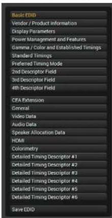
Select an EDID from Source panel and press Edit button to display Advanced EDID Editor window. The editor can read and write all descriptors, which are defined in the standards, including the additional CEA extensions. Any EDID from the device's memory or a saved EDID file can be loaded into the editor. The software resolves the raw EDID and displays it as readable information to the user. All descriptors can be edited, and saved in an EDID file, or uploaded to the User memory.
text_image
Basic EVID Vendor / Product information Display Parameters Power Management and Features Gamma / Color and Established Timings Standard Timings Preferred Timing Mode 2nd Descriptor Field 3rd Descriptor Field 4th Descriptor Field CEA Extension General Video Data Audio Data Speaker Allocation Data HDMI Colonometry Detailed Timing Descriptor #1 Detailed Timing Descriptor #2 Detailed Timing Descriptor #3 Detailed Timing Descriptor #4 Detailed Timing Descriptor #5 Detailed Timing Descriptor #6 Save EID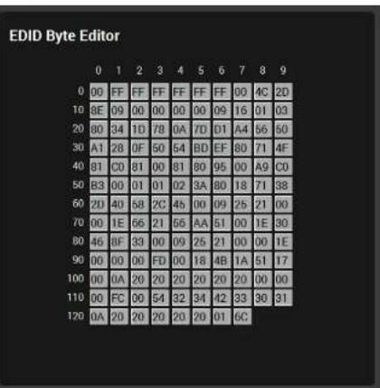
text_image
EDID Byte Editor 0 00 FF FF FF FF FF FF 00 4C 2D 10 8E 09 00 00 00 09 16 01 03 20 80 34 1D 78 0A 7D 01 A4 56 50 30 A1 28 0F 50 54 BD EF 80 71 4F 40 81 C0 81 00 81 80 95 00 A9 C0 50 B3 00 01 01 02 3A 80 18 71 38 60 2U 40 58 2C 46 00 09 25 21 00 70 00 1E 66 21 66 AA 51 00 1E 30 80 46 8F 33 00 09 25 21 00 00 1E 90 00 00 00FD 00 18 4B 1A 51 17 100 00 0A 20 20 20 20 20 20 20 00 00 110 00 FC 00 54 32 34 42 33 30 31 120 0A 20 20 20 20 20 01 6CEDID Editor Window
5.4.5. Creating an EDID
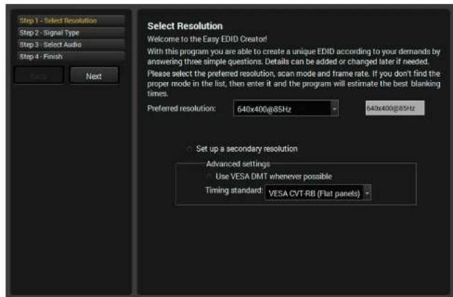
Since above mentioned Advanced EDID Editor needs more complex knowledge about EDID, Lightware introduced a wizard-like interface for fast and easy EDID creation. With Easy EDID Creator it is possible to create custom EDIDs in four simple steps. By clicking on the Create button below Source panel, Easy EDID Creator is opened in a new window.
text_image
Step 1 - Select Resolution Step 2 - Signal Type Step 3 - Select Audio Step 4 - Finish Next Select Resolution Welcome to the Easy EDID Creator! With this program you are able to create a unique EDID according to your demands by answering three simple questions. Details can be added or changed later if needed. Please select the preferred resolution, scan mode and frame rate. If you don't find the proper mode in the list, then enter it and the program will estimate the best blanking times. Preferred resolution: 640x400@85Hz 640x400@85Hz Set up a secondary resolution Advanced settings Use VESA DMT whenever possible Timing standard: VESA CVT-RB (Flat panels)Easy EDID Creator Window
5.5. Settings Menu
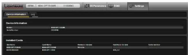
5.5.1. Device Information
text_image
LIGHTWARE SENA: 40N-2PT-TX30R 0158EN3 NO Parameters: LDD Settings Device information Log Device Information Network: 90000PT-1000W Satellite: 90000W Installed Cards Server: Card Name Security Server Network Server Network ID: 90000PT-100W Network Network ID: 90000PT-100W NetworkDevice Information Tab in the Settings Menu
The serial number, installed firmware version and the hardware revision of the device is shown under the Device Information tab.
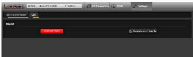
5.5.2. Log
Events logged by the device and report generators can be found on Log tab.
text_image
LIGHTWARE SERIAL HDMI OPT 10000K 0105890 3D Parameters EOD Settings Device information Log Report Download report Generate report from fileLog tab in the Settings Menu
LDC is able to collect information from the device and save it to a report file. This information package can be sent to Lightware support team when a problem may arise with the device.
Press the red button: Generate report file.
LDC collects the needed information; this may take up to 5 minutes.
After generating the report, a Save as dialog box appears. Select the folder where you want to save the report file. The default file name can be changed.
The report contains the following device-dependent information (if available):
• Device type and serial number,
- Firmware version,
- All EDID headers and status (emulated, dynamic, factory, user).
Open Custom Report from File
The Controller Software is able to send a custom command file to other Lightware devices (e.g. another HDMI-OPT series extender). The command file can be generated by Lightware support. This is needed when some special commands have to be used for configuring the device or troubleshooting.
INFO: This function is only for special troubleshooting cases.
5.6. Terminal Window
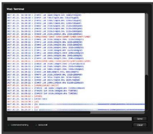
This general purpose terminal is intended mainly for testing and debugging purposes. The command text can be typed directly.
text_image
Web Terminal IP17_03.24 16:50:58 C (CH93) UR 1660-24016, km 5600-7600(58) IP17_03.24 16:50:59 C (CH93) UR 700-75416, km 200-4726(60) IP17_03.24 16:50:58 C (CH93) UR 1200-120916, km 5200-72016(61) IP17_03.24 16:50:58 C (CH93) UR 1200-120916, km 2200-72016(62) IP17_03.24 16:50:58 C (CH93) UR 1500-154456, km 3200-18881(63) IP17_03.24 16:50:58 C (CH93) UR 1500-154456, km 3200-18881(64) IP17_03.24 16:50:58 C (CH93) UR 1500-154456, km 3200-18881(65) IP17_03.24 16:50:58 C (CH93) UR 1500-154456, km 3200-18881(66) IP17_03.24 16:50:58 C (CH93) UR 1500-154456, km 3200-18881(67) IP17_03.24 16:50:58 C (CH93) UR 1500-154456, km 3200-18881(68) IP17_03.24 16:50:58 C (CH93) UR 1500-154456, km 3200-18881(69) IP17_03.24 16:50:58 C (CH93) UR 1500-154456, km 3200-18881(70) IP17_03.24 16:50:58 C (CH93) UR 1500-154456, km 3200-18881(71) IP17_03.24 16:50:58 C (CH93) UR 1500-154456, km 3200-18881(72) IP17_03.24 16:50:58 C (CH93) UR 1500-154456, km 3200-18881(73) IP17_03.24 16:50:58 C (CH93) UR 1500-154456, km 3200-18881(74) IP17_03.24 16:50:58 C (CH93) UR 1500-154456, km 3200-18881(75) IP17_03.24 16:50:58 C (CH93) UR 1500-154456, km 3200-18881(76) IP17_03.24 16:50:58 C (CH93) UR 1500-154456, km 3200-18881(77) IP17_03.24 16:50:58 C (CH93) UR 1500-154456, km 3200-18881(78) IP17_03.24 16:50:58 C (CH93) UR 1500-154456, km 3200-18881(79) IP17_03.24 16:50:58 C (CH93) UR 1500-154456, km 3200-18881(80) IP17_03.24 16:50:58 C (CH93) UR 1500-154456, km 3200-18881(81) IP17_03.24 16:50:58 C (CH93) UR 1500-154456, km 3200-18881(82) IP17_03.24 16:50:58 C (CH93) UR 1500-154456, km 3200-18881(83) IP17_03.24 16:50:58 C (CH93) UR 1500-154456, km 3200-18881(84) IP17_03.24 16:50:58 C (CH93) UR 1500-154456, km 3200-18881(85) IP17_03.24 16:50:58 C (CH93) UR 1500-154456, km 3200-18881(86) IP17_03.24 16:50:58 C (CH93) UR 1500-154456, km 3200-18881(87) IP17_03.24 16:50:58 C (CH93) UR 1500-154456, km 3200-18881(88) IP17_03.24 16:50:58 C (CH93) UR 1500-154456, km 3200-18881(89) IP17_03.24 16:50:58 C (CH93) UR 1500-154456, km 3200-18881(90) IP17_03.24 16:50:58 C (CH93) UR 1500-154456, km 3200-18881(91) IP17_03.24 16:50:58 C (CH93) UR 1500-154456, km 3200-18881(92) IP17_03.24 16:50:58 C (CH93) UR 1500-154456, km 3200-18881(93) IP17_03.24 16:50:58 C (CH93) UR 150O-CH93A, km - [C] = [C] = [C] IP17_03.24 16:50:58 C (CH93) UR 7E[O] = [C] = [C] IP17_03.24 16:50:58 C (CH93) UR 7E[O] = [C] = [C] IP17_03.24 16:5O] = [C] = [C] IP17_03.24 16:5O] = [C] = [C] IP17_03.24 16:5O] = [C] = [C] IP17_03.24 16:5O] = [C] = [C] IP17_03.24 16:5O] = C[O] IP17_03.24 2b] = [C] = [C] IP17_03.24 2b] = [C] = [C] IP17_03.24 2b] = [C] = [C] IP₁7_₀₃₄₂₅₅₅₅₅₅₅₅₅₅₅₅₅₅₅₅₅₅₅₅₅₅₅₅₅₅₅₅₅₅₅₅₅₅₅₅₅₅₅₅₅₅₅₅₅₅₅₅₅₅₆] IP₁7_₀₃₄₂₅₅₅₅₅₅₅₅₅₅₅₅₅₅₅₅₅₅₅₅₅₅₅₅₅₅₅₅₅₅₅₅₅₅₅₅₅₅₅₅₅₅₅₅ₑ IP₁7_₀₃₄₂₅₅₅₅₅₅₅₅₅₅₅₅₅₅₅₅₅₅₅₅ₑ IP₁7_₀₃₄₂ᵢᵢᵢᵢᵢᵢᵢᵢᵢᵢᵢᵢᵢᵢᵢᵢᵢᵢᵢᵢᵢᵢᵢᵢᵢᵢᵢᵢᵢᵢᵢᵢᵢᵢᵢᵢᵢᵢᵢᵢᵢᵢᵢᵢᵢᵢᵢᵢᵢᵢᵣ IP₁7_₀₃₄₂₁c IP₁7_₀₃₄₂₁c IP₁7_₀₃₄₂₁c IP₁7_₀₃₄₂₁c IP₁7_₀₃₄₂₁c IP₁7_₀₃₄₂₁c IP₁7_₀₃₄₂₁c IP₁7_₀₃d IP₁7_₀c IP₁7_₀c IP₁7_₀c IP₁7_₀c IP₁7_₀c IP₁7_₀c IP₁7_₀c IP₁7_₀c IP₁7_₀c IP₁7_₀c IP₁7_₀c IP₁7_₀c IP₁7_₀c IP₁T IP₁T IP₁T IP₁T IP₁T IP₁T IP₁T IP₁T IP₁T IP₁T IP₁T IP₁T IP₁T IP₁T IP₁T IP₁T IP₁T IP₁T IP₁T IP₁T IP₁T IP₁T IP₁T IP₁T IP₁T IP₁t IP₁t IP₁t IP₁t IP₁t IP₁t IP₁t IP₁t IP₁t IP₁t IP₁t IP₁t IP₁t IP₁t IP₁t IP₁t IP₁t IP₁t IP₁t IP₁t IP₁t IP₁t IP₁t IP₁t IP₁t IP₁tt IP₁tt ICU : [I] = [I] = [I] = [I] = [I] = [I] = [I] = [I] = [I] = [I] = [I] = [I] = [I] = [I] = [I] = [I] = [I] = [I] = [I] = [I] = [I] = [I] = [I] = [I] = [I] = [I]Terminal Window
By default commands are automatically surrounded by framing brackets. Every sent command and every received response gets an arrow (-> or <-) prefix, and has different font colors in order to help to distinguish.
The timecode in every row shows the exact time when the command was sent or the response received.
If the Command framing checkbox is unchecked, you can send multiple commands together, however in this case you have to type in the framing brackets manually.
The terminal can also be opened after starting the LDC - press the Terminal button on the Device discovery page on the bottom of the window.
TIPS AND TRICKS: The typed commands can be "browsed" when the cursor is in the command line and you press the up button on the keyboard. The commands are stored until the LDC is closed.

Firmware Upgrade
This chapter is meant to help customers perform firmware upgrades on our products by giving a few tips on how to start and by explaining the features of the Bootloader software. To get the latest software and firmware pack please contact support@lightware.com.
▶ UPGRADING STEPS IN A NUTSHELL
▶ DETAILED INSTRUCTIONS
WARNING! All EDIDs in the User Memory will be lost after the firmware upgrade. Save the user EDIDs before processing the upgrade.
6.1. Upgrading Steps in a Nutshell
Step 1. Installing the Lightware Bootloader Software.
Step 2. Downloading and saving all the firmware files that you want to upgrade.
Step 3. Connecting the Lightware device and the computer via RS-232 port.
Step 4. Starting the Lightware Bootloader application.
Step 5. Establishing the connection with the device
Step 6. Selecting firmware to upgrade.
Step 7. Starting the upgrade process.
Step 8. Restarting the device.
6.2. Detailed Instructions
Use the Lightware Bootloader application to upgrade the device's firmware. The extender can only be upgraded via RS-232, so connect the device directly to the Windows based computer with an RS-232 cable.
Step 1. Installing the bootloader application with Installer_LW_bootloader.exe.
Step 2. Downloading and saving all the firmware files that you want to upgrade. If you have a zipped archive, extract it.
Step 3. Connecting the Lightware device and the computer via USB port.
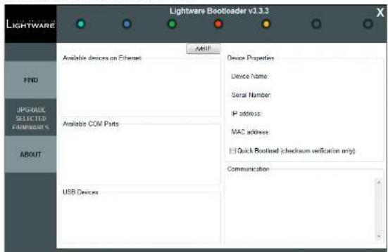
Step 4. Starting the Lightware Bootloader application.
text_image
Lightware Bootloader v1.3.3 LIGHTWARE FIND UPGRADE SELECTED PROMINER'S ABOUT Available devices on Ethernet Available COM Parts USB Devices Add'l Device Properties Device Name: Serial Number: IP address: MAC address: Quick Bootload (checksum verification only) Communication


- Firmware Upgrade HDMI-OPT series - User's Manual 26
Step 5. Establishing the connection with the device.
During this mode all the status LEDs light continuously.
Click on the Find button. Check the Available COM Ports panel to find your device. Double click on the desired COM port, then click YES to establish connection with the extender. It will take few seconds to get all information from the device.
When the connection is established, the device is automatically switched to bootload mode.
INFO: During bootload mode all the status LEDs light continuously.
Switching the Transmitter to Bootload Mode Manually
a) Turn the EDID rotary switches into #99 position.
b) Turn the BAUD RATE rotary switch into #9 position.
c) Connect the 5V DC to the transmitter unit.
d) While pressing and holding the LEARN button plug the 5V DC wall adaptor to the electric outlet.
Switching the HDMI-OPT-RX200R receiver to Bootload Mode Manually
a) Connect the 5V DC to the receiver unit.
b) While pressing and holding the SECONDARY FUNCTION button plug the 5V DC wall adaptor to the electric outlet.
Review the Firmware Versions
After the connection is made, the device properties, and the installed controller module is displayed.
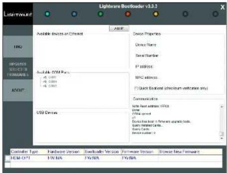
text_image
Lightware Bootloader v3.0.1 LHWARE Available Devices on Ethernet Device Properties Device Name Serial Number IP address MAC address... (Quick Ethernet (checkmark verification only)) Communication Data Write Back address: OFFCD Drive Office format IP Send back location in front-end upgrade code. Query installed Center Query Cache Device Location: 2 ACB-007 FV/NA FV/NA FV/NAStep 6. Browse for the new firmware.
Click the corresponding cell in the Browse New Firmware column. A dialog pops up, to confirm if you really want to modify the path. Now you can browse for the new firmware file to upload. After opening the new file, the new firmware field will contain the name of the firmware file.
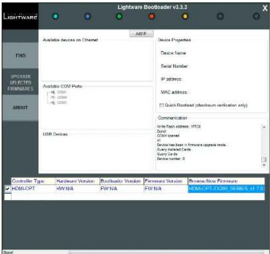
text_image
Lightware Bootloader v3.3.3 LIGHTWARE ASIF Available devices on Ethernet Device Properties Device Name Serial Number IP address: MAC address: Quick Bootload (checkrum verification only) Device Name Serial Number IP address: MAC address: Quick Bootload (checkrum verification only) Device Name Serial Number IP address: MAC address: Quick Bootload (checkrum verification only) Device Name Serial Number IP address: MAC address: Quick Bootload (checkrum verification only) Device Name Serial Number IP address: MAC address: Quick Bootload (checkrum verification only) Device Name Serial Number IP address: MAC address: Quick Bootload(10000000000000000000000000000000000000000000000000000000000000000000000000000 FIND UPGRADE SPECTED FIRIMWARES ABOUT Available COM Parts - IP: CC261 - IP: CC264 - IP: CC265 USB Devices Communication Write Tach address: 17TC6 Dord: CC264 opened 6 Device has been in firmware upgrade mode. Query installed Cards. Query Cards Device number: 8 Controller Type Hardware Version Bootloader Version Firmware Version Reverse New Firmware HOMLOPT HW N/A PW N/A FW N/A HOMLOPT-DX288 SERIES >17.3Step 7. Upgrade firmware.
Click Upgrade selected firmwares button. A confirmation message appears. After clicking the Yes button the selected controllers are being reprogrammed, with the firmware you selected. If you select a file that does not fit for the selected controller, you will get an information message about which file is wrong. If you selected a controller to upgrade, but you had not selected a file for it, then you will also get an information message about which file is missing.


- Firmware Upgrade HDMI-OPT series - User's Manual 27
Quick Bootload mode can be switched on or off any time. It makes the bootloader software faster by only checking the checksum of the controller. No data verification is done after writing if the checksum was correct.
A progress bar will show the current state of the reprogramming. With some controller type an erasing process will take place first, and then the programming is done, so the progress bar runs up twice.
When the reprogramming is finished, a Donel message will appear in the bottom left corner. The application closes the connection, and the device restarts.
Step 8. Done!
If the upgrade was successful, the following window pops up:
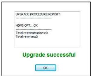
text_image
UPGRADE PROCEDURE REPORT HDMI-OPT...OK Total retransmissions:0 Total rewrites:0 Upgrade successful OKNow you can close the application, or you can select another device to upgrade. After closing the bootloader application, switch the upgraded devices off and then on. Now the extender is ready to be used with the new firmware!
7
Troubleshooting
Usually, if the system seems not to transport the signal as expected, the best strategy for troubleshooting is to check signal integrity through the whole signal chain starting from source side and moving forward to sink device end.
At first, check front panel LEDs and take the necessary steps according to their states. For more information about status, LEDs refer to The Legend of Status LEDs section.
Pictogram Legend
Section to connections/cabling.
Section to front panel operation.
Section to LDC software.
| Symptom Root cause Action Refer to | |||
| Video/audio signal | |||
| No picture on the output | Device or devices are not powered properly | Check the extender and the other devices if they are properly powered; try to unplug and reconnect them. | 3.3.1 |
| Cable connection problem | Cables must fit very well, check all the connectors. | 3.3 | |
| Endface surface of the fiber optical cable became contaminated | Use special fiber optical cable cleaning equipment to clean it carefully. | ||
| No incoming signal (transmitter) | If the Video Clock Present LED is not illuminated (in PRIMARY mode), no DVI signal is present on the DVI input port. Check the source device and the HDMI cable. | 3.3 | |
| No incoming signal (receiver) | If the Video Clock Present LED is not illuminated (in PRIMARY mode), no signal is present on the optical input port. Check the source device and the fiber cable. | 3.3 | |
| Invalid EDID is selected (transmitter) | Check the Emulated EDID Invalid LED (in SECONDARY mode). If it is illuminated red, then an invalid EDID or an empty memory address is selected. Select a valid EDID. | 4.2.2 | |
| Strange colors are displayed | Incorrect colorspace has been applied | HDMI-OPT units do not support colorspace conversion between HDMI YUV and RGB. Change the colorspace on the HDMI source manually or modify an EDID with the Lightware Control Software to not support YUV colorspace. | 5.4.4 |

Technologies
The following sections contain descriptions and useful technical information how the devices work in the background. The content is based on experiences and cases we met in the practice. These sections help to understand features and technical standards like the followings:
▶ EDID MANAGEMENT
HDCP MANAGEMENT
▶ PIXEL ACCURATE RECLOCKING
▶ SERIAL MANAGEMENT
8.1. EDID Management
8.1.1. Understanding the EDID
The Extended Display Identification Data (EDID) is the passport of display devices (monitors, TV sets, projectors). It contains information about the capabilities of the display, such as supported resolutions, refresh rates (these are called Detailed Timings), the type and manufacturer of the display device, etc.
After connecting a source to a display (DVI, HDMI, DP), the source reads out the EDID to determine the resolution and refresh rate of the image to be transmitted.
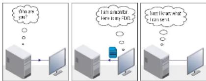
EDID Communication
Most DVI computer displays have 128-byte long EDID structure. However, Digital Televisions and HDMI capable displays may have another 128 bytes, which is called E-EDID and defined by CEA (Consumer Electronics Association). This extension contains information about additional Detailed Timings, audio capabilities, speaker allocation and HDMI capabilities. It is important to know that all HDMI capable devices must have CEA extension, but not all devices with CEA extension are HDMI capable.
Common Problems Related to EDID
Problem: "My system consists of the following: a computer, a Lightware device, a WUXGA (1920x1200) LCD monitor, and an SXGA (1280x1024) projector. I would like to see the same image on the monitor and the projector. What EDID should I choose on the Lightware device?"
Solution: If you want to see the image on both displays, you need to select the resolution of the smaller display (in this case SXGA), otherwise the smaller display may not show the higher resolution image.
Problem: "I have changed to a different EDID on an input port of the Lightware device to have a different resolution but nothing happens."
Solution: Some graphics cards and video sources read out the EDID only after power-up and later they do not sense that EDID has been changed. You need to restart your source to make it read out the EDID again.
8.1.2. Advanced EDID Management
Each DVI sink (e.g. monitors, projectors, plasma displays, etc...) must support the EDID data structure. Source BIOS and operating systems are likely to query the sink using DDC2B protocol to determine what pixel formats and interface are supported. DVI standard uses EDID data structure to identify the monitor type and capabilities. Most DVI sources (VGA cards, set top boxes, etc.) will output DVI signal after accepting the connected sink's EDID information. In the case of EDID readout failure or missing EDID, the source will not output DVI video signal.
Lightware devices provide the Advanced EDID Management function that helps system integration. The built-in EDID Router can store and emulate factory pre-programmed- and User programmable EDIDs. The EDID of the attached monitors or projectors for each output are stored in a non-volatile memory. This way the EDID of a monitor is available when the monitor is unplugged or switched off.
Any EDID can be emulated on any input. An emulated EDID can be copied from the EDID router's memory (static EDID emulation), or from the last attached monitor's memory (dynamic EDID emulation). For example, the Lightware device can be set up to emulate a sink device, which is connected to one of the outputs. In this case, the EDID automatically changes, if the monitor is replaced with another display device (as long as it has a valid EDID).
EDID is independently programmable for all inputs without affecting each other. All inputs have their own EDID circuit.
INFO: The user is not required to disconnect the video cable to change an EDID as opposed to other manufacturer's products. EDID can be changed even if a source is connected to the input and powered ON.
INFO: When EDID has been changed, the router toggles the HOTPLUG signal for 2 seconds. Some sources do not sense this signal. In such cases, the source device must be restarted or powered OFF and ON again.


- Technologies HDMI-OPT series - User's Manual 30
8.2. HDCP Management
Lightware Visual Engineering is a legal HDCP adopter. Several functions have been developed which help to solve HDCP related problems. Complex AV systems often have both HDCP and non-HDCP components. The extender allows transmitting HDCP encrypted and unencrypted signals. The devices will be still HDCP compliant as they will never output an encrypted signal to a non-HDCP compliant display device. If an encrypted signal is switched to a non-compliant output, a red screen alert or muted screen will be shown.
8.2.1. Protected and Unprotected Content
Many video sources send HDCP protected signal if they detect that the sink is HDCP capable – even if the content is not copyrighted. This can cause trouble if an HDCP capable device (e.g. an HDMI-OPT series extender) is connected between the source and the display. In this case, the content cannot be viewed on non-HDCP capable displays and interfaces like event controllers.
8.2.2. Real Life Examples
HDCP-Compliant Sink

flowchart
graph LR
    A["Protected content"] -->|Encrypted signal| B["HDMI cable"]
    B --> C["HDMI-OPT series transmitter"]
    C -->|Optical cable| D["HDMI-OPT series receiver"]
    D -->|Encrypted signal| E["HDMI cable"]
    E --> F["HDCP-compliant sink"]
HDCP-compliant sink
All the devices are HDCP-compliant, both protected and unprotected content is transmitted and displayed on the sink device.
Non-HDCP Compliant Sink 1.

flowchart
graph LR
    A["Unprotected content"] <--> B["Non-encrypted signal"]
    B <--> C["HDMI cable"]
    C --> D["HDMI-OPT series transmitter"]
    D --> E["Optical cable"]
    E --> F["HDMI-OPT series receiver"]
    F --> G["Non-encrypted signal"]
    G <--> H["HDMI cable"]
    H --> I["Non-HDCP compliant sink"]
Non-HDCP compliant sink displaying unprotected content
Non-HDCP compliant sink is connected to the receiver. Since the content is unprotected the image will be visible on the sink.
Non-HDCP Compliant Sink 2.

flowchart
graph LR
    A["Protected content"] <-->|Encrypted signal HDMI cable| B["HDMI-OPT series transmitter"]
    B <-->|Optical cable| C["HDMI-OPT series receiver"]
    C <-->|HDMI cable| D["Non-HDGP compliant sink"]
Non-HDCP compliant sink and protected content
The layout is the same as in the previous case: non-HDCP compliant display device is connected to the receiver but the source would send protected content with encryption. The sink is not HDCP-compliant, thus, it will not display the video signal (but blank/red/muted/etc. screen). The solution is to replace the display device to an HDCP-capable one.
8.3. Pixel Accurate Reclocking
Signal reclocking is an essential important procedure in digital signal transmission. After passing the reclocking circuit, the signal becomes stable, jitter-free, and can be transmitted over more equipment like processors, or event controllers. Without reclocking, sparkles, noise, and jaggies appear on the image.
Lightware's sophisticated Pixel Accurate Reclocking technology fixes more problems than general TMDS reclocking. It removes not only intra-pair skew but inter-pair skew as well. The Pixel Accurate Reclocking circuit eliminates the following errors:
Intra-pair skew
Skew between the + and - wires within a differential wire pair (e.g. Data2- and Data2+). It's caused by different wire lengths or slightly different wire construction (impedance mismatch) in DVI cable. It results in jitter.
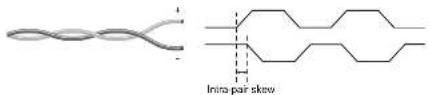
text_image
Intra pair skewInter-pair skew
Skew between two differential wire pairs in a cable. It is caused by different wire pair lengths or different number of twists in the DVI cable. Too much inter-pair skew results color shift in the picture or sync loss.
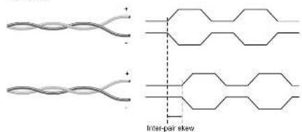
text_image
Inter-pair skewJitter
Signal instability in the time domain. The time difference between two signal transitions should be a fixed value, but noise and other effects cause variations.
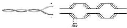
chemical
Diagram of a twisted polymer structure with labeled intermolecular distance JitterNoise
Electromagnetic interference between other electronic devices such as mobile phones, motors, etc. and the DVI cable are coupled onto the signal. Too much noise results in increased jitter.



- Technologies HDMI-OPT series - User's Manual 32
8.4. Serial Management
8.4.1. General Information
There are two types of devices in general serial communication.
- Data Terminal Equipment: Data Terminal Equipment (DTE) is an end instrument that converts user information into signals or reconverts received signals. Typical DTE devices: computers, LCD touch panels and control systems.
- Data Circuit-terminating Equipment: Data Circuit-terminating Equipment (DCE) is a device that sits between the DTE and a data transmission circuit. It is also called data communication equipment and data carrier equipment. Typical DCE devices: projectors, industrial monitors and amplifiers.
Among others the pin assignment is different between DTE and DCE.
| DTE DCE | ||
| Pin 2: RD TD | ||
| Pin 3: TD RD | ||
RD: Received Data (digital input)
TD: Transmitted Data (digital output)
INFO: HDMI-OPT transmitters (TX200R, TX100R) are DCE units and receivers (RX200R, RX100R) are DTE units according to their pin-outs.
Different type of serial cables must be used between different serial devices.
| DTE DCE | ||
| DTE Null-modem TD | ||
| DCE Straight Null-modem* | ||
* In general contact DCE with DCE by tail-circuit serial cable.
8.4.2. Types of Serial Cables
| Straight Serial Cable Null-modem Serial Cable | |
| Straight pin-outs both ends. | Straight pin-out at the one end and cross pin-out at the other end (interchange lines of TX and RX). |
Serial cables between devices may have male or female plugs and their type may be straight or null-modem in usual.
ATTENTION! The cable type does not depend on the plug type.
8.4.3. RS-232 Signal Transmission over Lightware Extender Devices
The following examples describe the detailed integration of Lightware devices between different RS-232 pin assignment units.
INFO: HDMI-OPT transmitters (TX200R, TX100R) are DCE units and receivers (RX200R, RX100R) are DTE units according to their pin-outs.
Extending RS-232 between DTE and DCE Third-party Devices
Connect null-modem serial cable between controller system (DTE) and the transmitter (DTE) and straight serial cable between receiver (DTE) and projector (DCE).
| Controller system | Transmitter | Receiver | Projector | |||
| DTL | Female: Mini Straight serial cable | DCL | Transmission interface | BTE | Female: Mini Straight serial cable | DCE |
| Pin 2: RC | ← | Pin 2: ID | ← | Pin 2: RD | ← | Pin 2: ID |
| Pin 3: ID | → | Pin 3: RC | ← | Pin 3: ID | ← | Pin 3: RC |
RS-232 Connection Example between a Controller System and a Projector
Extending RS-232 between DTE and DTE Third-party Devices
Connect straight serial cable between controller system (DTE) and the transmitter (DCE) and null-modem serial cable between receiver (DTE) and computer (DTE).
| Computer | Transmitter | Receiver | Computer | ||||
| DTE | letiate - More Single terminal cable | DCE | Transmission interface | DTE | letiate - Blue Full modular serial cable | DTE | DTE |
| Pin 2:3DPin 3:1D | Pin 2:TDPin 3:RC | Pin 2:3DPin 3:RC | Pin 2:3DPin 3:TC | Pin 2:3DPin 3:TC | Pin 2:RCPin 3:TC | ||
RS-232 Connection Example between Two Computers

Appendix
SPECIFICATION
▶ MAXIMUM EXTENSION DISTANCES
MECHANICAL DRAWINGS
FACTORY EDID LIST
9.1. Specification
General
Compliance......CE
EMC (Emission)....EN 55032:2015
EMC (Immunity)......EN 55035:2017
Safety....EN 60065 Class II
Warranty 3 years
Cooling....Passive
Operating temperature 0 to +50°C (+32 to +122°F)
Operating humidity 10% to 90%, non-condensing
Power
Power supply....External power adaptor
Power adaptor.....In 100-240 V AC 50/60 Hz, Out 5V DC, 2.5 A
Power connector.... Locking DC connector (2.35 mm pin)
Power input 5V DC 1 A
Power consumption (Transmitters)....4 W (typ); 6W (max)
Power consumption (Receivers)....4 W (typ); 9W (max)
Enclosure
Material....1 mm steel
Dimensions in mm.....100.4 x 131.9 x 26 (excluding connectors)
Dimensions in inch ..... 3.953 x 5.193 x 1.023 (excluding connectors)
Net Weight (TX200R/RX200R) 410 g
Net Weight (TX100R/TX100/RX100R/RX100) 400 g
Optical Ports
Connector type....Standard simplex SC socket
Fiber......50/125 SC Multimode (preferred) 62.5/125 SC Multimode
Laser wavelengths - high speed 4 channel CWDM: 778; 800; 825; 850 nm
Laser wavelengths - low speed.....2 channel CWDM: 911; 980 nm
Laser class specification....Class 3R
Transmitter output OMA * -6.25 dBm (worst case)
Receiver OMA * sensitivity ....-14.25 dBm (worst case)
Optical loss budget....8 dBm (worst case)
Transmission distance 2600 meters (using OM4 type fiber)
* OMA: Optical Modulation Amplitude
Video Ports
Connector type....19-pole HDMI Type A receptacle
Standard ...... HDMI 1.3, DVI 1.0
Color depth...... maximum 36 bits, 12 bit/color
Format sRGB, YCbCr, xvYCC digital video
Maximum data rates....6.75 Gbps (2.25 Gbps /TMDS channel)
Maximum pixel clock....225 MHz
Video delay....0 frame
Resolutions...... all between 640x480 and 2048x1080 deep color
HDTV resolutions....720p, 1080i, 1080p
HDCP compliant.....Yes
EDID support......Advanced EDID management
Reclocking....Pixel Accurate Reclocking
EDID Emulation (Transmitters) ...... Yes, 50 factory preset, 48 user
programmable
Output mode ...... Automatic (DVI or HDMI)
Colorspace conversion......No


- Appendix HDMI-OPT series - User's Manual 34
Serial Ports
Connector type (Transmitters)......DE-9F (9-pole D-sub Female)
Connector type (Receivers)......DE-9M (9-pole D-sub Male)
Direction......Bidirectional
Baud rate 9600, 14400, 19200, 38400, 57600 Baud
Connectors / ESD protection (HBM EIA/JESD22-A114F)
HDMI input and output 19-pole HDMI Type A socket / 8 kV
Serial port (TX100R/TX200R transmitters)...... DE-9F (9-pole D-sub Female) / 15 kV
Serial port DE-9M (9-pole D-sub Male) / 15 kV
Optical fiber input and output ....Standard simplex SC socket / n.a.
Power connector.... Locking DC connector (2.5/5.5 mm) / 2 kV
9.2. Maximum Extension Distances
| OM1 OM2 | OM3 OM4 | |||
| (62.5/125) (50/125) (50/125) | (50/125) | |||
| 1080p@60Hz 24 bpp 250 m 600 m | 1200 m 2600 m | |||
| 1080p@60Hz 36 bpp 150 m 400 m | 800 m 1300 m | |||
| 4096x2048@30Hz 24 bpp | Not supported | 350 m 700 m | 1100 m | |
9.3. Mechanical Drawings
The following drawings present the physical dimensions of the device. HDMI-OPT-TX200R can be seen in the pictures but the dimensions are valid for all the models. Dimensions are in mm.
Front View Rear View
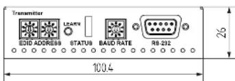
text_image
Transmitter EDID ADDRESS 9 STATUS BAUD RATE RB-232 100.4 26Bottom View
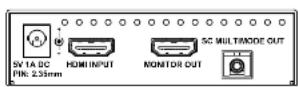
Top View
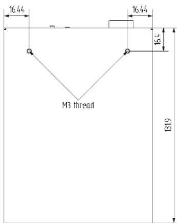
text_image
16.44 16.44 16.4 M3 thread B19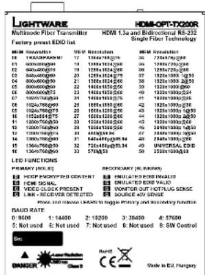
text_image
LIGHTWARE Multimode Fiber Transmitter Factory press EDD list HDM - Opt-TX200R Multi-lens Fiber Technology HDM - 1.3a and Bidirectional RS-232 Single Fiber Technology HDM Resolution: 95% Resolution 16 1744816250 1744816250 1744816250 16 1744816250 1744816250 1744816250 16 1744816250 1744816250 1744816250 16 1744816250 1744816250 16 16 1744816250 1744816250 1744816250 16 1744816250 1744816250 1744816250 16 1744816250 1744816250 15 16 1744816250 1744816250 1744816250 16 1744816250 1744816250 1744816250 16 1744816250 1744816250 13 16 1744816250 1744816250 1744816250 16 1744816250 1744816250 1744816250 16 1744816250 1744816250 19 16 1744816250 1744816250 1744816250 16 1744816250 1744816250 1744816250 16 1744816250 1744816250 18 16 1744816250 1744816250 1744816250 16 1744816250 1744816250 1744816250 16 1744816250 1744816250 12 16 1744816250 1744816250 1744816250 16 1744816250 1744816250 1744816250 16 1744816250 1744816250 9 16 1744816250 1744816250 9 16 1744816250 1744816250 9 16 1744816250 3 3 3 3 3 3 3 3 3 3 3 3 3 3 3 3 3 3 3 3 3 3 3 3 3 3 3 3 3 3 3 3 3 3 3 3 3 3 3 3 3 3 3 3 3 3 3 3 3 3 39.4. Factory EDID List
| Mem. | Resolution Type | |||||
| F1 640 x | 480 @ 60.0 Hz DVI | |||||
| F2 640 x | 480 @ 75.0 Hz DVI | |||||
| F3 848 x | 480 @ 60.0 Hz DVI | |||||
| F4 800 x | 800 @ 50.0 Hz DVI | |||||
| F5 800 x | 800 @ 60.3 Hz DVI | |||||
| F6 800 x | 800 @ 74.9 Hz DVI | |||||
| F7 1024 x | 768 @ 49.98 Hz DVI | |||||
| F8 1024 x | 768 @ 60.00 Hz DVI | |||||
| F9 1024 x | 768 @ 75.20 Hz DVI | |||||
| F10 1152 x | 864 @ 75.00 Hz DVI | |||||
| F11 1280 x | 768 @ 50.00 Hz DVI | |||||
| F12 1280 x | 768 @ 39.92 Hz DVI | |||||
| F13 1280 x | 768 @ 75.00 Hz DVI | |||||
| F14 1360 x | 768 @ 60.10 Hz DVI | |||||
| F15 1364 x | 768 @ 50.00 Hz DVI | |||||
| F16 1364 x | 768 @ 59.93 Hz DVI | |||||
| F17 1364 x | 768 @ 74.98 Hz DVI | |||||
| F18 1280 x | 1024 @ 50.00 Hz DVI | |||||
| F19 1280 x | 1024 @ 60.10 Hz DVI | |||||
| F20 1280 x | 1024 @ 75.10 Hz DVI | |||||
| F21 1366 x | 1024 @ 59.99 Hz DVI | |||||
| F22 1400 x | 1050 @ 49.99 Hz DVI | |||||
| F23 1400 x | 1050 @ 59.99 Hz DVI | |||||
| F24 1400 x | 1050 @ 75.00 Hz DVI | |||||
| F25 1680 x | 1050 @ 59.99 Hz DVI | |||||
| F26 1600 x | 1200 @ 50.00 Hz DVI | |||||
| F27 1600 x | 1200 @ 60.00 Hz DVI | |||||
| F28 1920 x | 1200 @ 59.55 Hz DVI | |||||
| F29 1920 x | 1200 @ 50.00 Hz DVI | |||||
| F30 1442 x | 480 @ 60.30 Hz HDMI | |||||
| Mem. Resolution Type | |||||
| F31 540 x 480 @ 59.34 Hz HDMI | |||||
| F32 720 x 480 @ 59.02 Hz HDMI | |||||
| F33 1440 x 288 @ 50.60 Hz HDMI | |||||
| F34 720 x 576 @ 50.00 Hz HDMI | |||||
| F35 1280 x 720 @ 50.00 Hz HDMI | |||||
| F36 1280 x 720 @ 60.00 Hz HDMI | |||||
| F37 1920 x 1080 @ 50.30 Hz HDMI | |||||
| F38 1920 x 1080 @ 50.00 Hz HDMI | |||||
| F39 1920 x 1080 @ 60.50 Hz HDMI | |||||
| F40 1920 x 1080 @ 24.00 Hz HDMI | |||||
| F41 1920 x 1080 @ 24.99 Hz HDMI | |||||
| F42 1920 x 1080 @ 30.00 Hz HDMI | |||||
| F43 1920 x 1080 @ 50.00 Hz HDMI | |||||
| F44 1920 x 1080 @ 49.99 Hz HDMI | |||||
| F45 1920 x 1080 @ 60.00 Hz HDMI | |||||
| F46 2048 x 1080 @ 49.99 Hz HDMI | |||||
| F47 2048 x 1080 @ 50.00 Hz HDMI | |||||
Legend
D: DVI EDID
H: HDMI EDID
Please note that minor changes in the factory EDID list may be applied in farther firmware versions.


- Appendix HDMI-OPT series – User's Manual 36
9.5. Further Information
Limited Warranty Statement
- Lightware Visual Engineering LLC (Lightware) warrants to all trade and end user customers that any Lightware product purchased will be free from manufacturing defects in both material and workmanship for three (3) years from purchase unless stated otherwise below. The warranty period will begin on the latest possible date where proof of purchase/delivery can be provided by the customer. In the event that no proof can be provided (empty 'Date of purchase' field or a copy of invoice), the warranty period will begin from the point of delivery from Lightware.
1.1. 25G and MODEX product series will be subject to a seven (7) year warranty period under the same terms as outlined in this document.
1.2. If during the first three (3) months of purchase, the customer is unhappy with any aspect of a Lightware product, Lightware will accept a return for full credit.
1.3. Any product that fails in the first six (6) months of the warranty period will automatically be eligible for replacement and advanced replacement where available. Any replacements provided will be warranted for the remainder of the original unit's warranty period.
1.4. Product failures from six (6) months to the end of the warranty period will either be repaired or replaced at the discretion of Lightware. If Lightware chooses to replace the product then the replacement will be warranted for the remainder of the original unit's warranty period.
- The above-stated warranty and procedures will not apply to any product that has been:
2.1. Modified, repaired or altered by anyone other than a certified Lightware engineer unless expressly agreed beforehand.
2.2. Used in any application other than that for which it was intended.
2.3. Subjected to any mechanical or electrical abuse or accidental damage.
2.4. Any costs incurred for repair/replacement of goods that fall into the above categories (2.1., 2.2., 2.3.) will be borne by the customer at a pre-agreed figure.
- All products to be returned to Lightware require a return material authorization number (RMA) prior to shipment and this number must be clearly marked on the box. If an RMA number is not obtained or is not clearly marked on the box, Lightware will refuse the shipment.
3.1. The customer will be responsible for in-bound and Lightware will be responsible for out-bound shipping costs.
3.2. Newly repaired or replaced products will be warranted to the end of the originally purchased products warranty period.
Document Revision History
| Rev. | Release date | Changes Editor | |
| 1.0 13-08-2012 Initial version Zsolt Marko | |||
| 1.1 15-12-2015 | Safety instructions updated, CE page pulled out | Laszlo Zsedenyi | |
| 2.0 10-04-2017 | Minor updates to Software Control (LDC) chapter, updated Firmware Upgrade and Troubleshooting chapters | Tamas Forgacs | |
| 2.1 15-05-2018 HDCP description corrected | Laszlo Zsedenyi | ||
| 3.0 13-08-2018 New format introduced | Judit Barsony | ||
Contact Us
sales@lightware.com
+36 1 255 3800
support@lightware.com
+36 1 255 3810
Lightware Visual Engineering LLC.
Peterdy 15, Budapest H-1071, Hungary
www.lightware.com
©2018 Lightware Visual Engineering. All rights reserved. All trademarks mentioned are the property of their respective owners. Specifications subject to change without notice