DVI-TP-TX200 - Audio/video extender Lightware - Free user manual and instructions
Find the device manual for free DVI-TP-TX200 Lightware in PDF.


User questions about DVI-TP-TX200 Lightware
0 question about this device. Answer the ones you know or ask your own.
Ask a new question about this device
Download the instructions for your Audio/video extender in PDF format for free! Find your manual DVI-TP-TX200 - Lightware and take your electronic device back in hand. On this page are published all the documents necessary for the use of your device. DVI-TP-TX200 by Lightware.
USER MANUAL DVI-TP-TX200 Lightware
visual engineering LIGHTWARE
DVI-TP-TX300
DVI-TP-TX200
DVI-TP-RX100
User's Manual
text_image
MANUAL EQ AUTO EQ SIGNAL PRESENT MONITOR HOTPLUG EQ LEVEL 0 dB +40 dB EQ MODE SELECTION LIGHTINUE SINGLE LIME OFF TWISTEN PLTR RECOOKING RECORDER EDID ADDRESS LEARN EDID STATUS EDID INVALID EDID VALID MONITOR SRC +5V DVI INPUT LEARN EDID STATUS EDID INVALID EDID VALID MONITOR SRC +5V DVI INPUTSAFETY INSTRUCTIONS
Class II apparatus construction.
The equipment should be operated only from the power source indicated on the product.
To disconnect the equipment safely from power, remove the power cord from the rear of the equipment, or from the power source. The MAINS plug is used as the disconnect device, the disconnect device shall remain readily operable.
There are no user-serviceable parts inside of the unit. Removal of the cover will expose dangerous voltages. To avoid personal injury, do not remove the cover. Do not operate the unit without the cover installed.
The apparatus shall not be exposed to dripping or splashing and that no objects filled with liquids, such as vases, shall be placed on the apparatus. No naked flame sources, such as lighted candles, should be placed on the apparatus.
The appliance must be safely connected to multimedia systems. Follow instructions described in this manual.
Ventilation
For the correct ventilation and avoid overheating ensure enough free space around the appliance. Do not cover the appliance, let the ventilation holes free and never block or bypass the ventilators (if any).
WARNING
To prevent injury, the apparatus is recommended to securely attach to the floor/wall or mount in accordance with the installation instructions.
WEEE ( Waste Electrical & Electronic Equipment )
Correct Disposal of This Product


This marking shown on the product or its literature, indicates that it should not be disposed with other household wastes at the end of its working life. To prevent possible harm to the environment or human health from uncontrolled waste disposal, please separate this from other types of wastes and recycle it responsibly to promote the sustainable reuse of material resources.
Household users should contact either the retailer where they purchased this product, or their local government office, for details of where and how they can take this item for environmentally safe recycling.
Business users should contact their supplier and check the terms and conditions of the purchase contract. This product should not be mixed with other commercial wastes for disposal.
Table of contents
1. INTRODUCTION....6
2. GENERAL DESCRIPTION....6
2.1. BOX CONTENTS....6
2.2. TRANSMITTER FEATURES (DVI-TP-TX200 AND TX300)....6
2.3. RECEIVER FEATURES (DVI-TP-RX100) 7
2.4. UNDERSTANDING EDID 8
2.4.1. Basics 8
2.4.2. Common problems related to EDID 8
2.5. ADVANCED EDID MANAGEMENT (DVI-TP-TX200/TX300) 9
2.6. TMDS RECLOCKING (DVI-TP-RX100) 9
2.7. FIBER CABLE POWERING.... 10
2.8. APPLICATIONS....11
2.9. FRONT AND REAR VIEW 13
2.9.1. Front view of DVI-TP-TX200/TX300 13
2.9.2. Rear view of DVI-TP-TX200/TX300 14
2.9.3. Front view of DVI-TP-RX100.... 15
2.9.4. Rear view of DVI-TP-RX100 16
2.10. ELECTRICAL CONNECTIONS.... 17
2.10.1. DVI inputs and outputs.... 17
2.10.2. CATx inputs and outputs 17
3. OPERATION OF DVI-TP-TX200/TX300 18
3.1. POWER.... 18
3.2. LEARNING THE EDID 18
3.3. SWITCHING THE EDID 19
3.4. FACTORY PRESET EDID LIST 19
4. OPERATION OF DVI-TP-RX100 20
4.1. POWER....20
4.2. ADJUSTING THE INPUT EQUALIZATION 20
4.3. MAXIMUM TWISTED PAIR DISTANCES.... 21
5. TROUBLESHOOTING 21
5.1. THERE IS NO PICTURE.... 21
6. MECHANICAL DRAWINGS 23
6.1. DVI-TP-TX200/TX300 23
6.1.1. Top view 23
6.1.2. Front view (controls and input) 23
6.1.3. Rear view (outputs and power) 24
6.1.4. Bottom view 24
6.2. DVI-TP-RX100 25
6.2.1. Top view 25
6.2.2. Front view (controls) 25
6.2.3. Rear view (inputs, output and power) 26
6.2.1. Bottom view 26
7. SPECIFICATIONS....27
8. WARRANTY 28
9. DOCUMENT REVISION HISTORY....28
1. Introduction
Dear Customer,
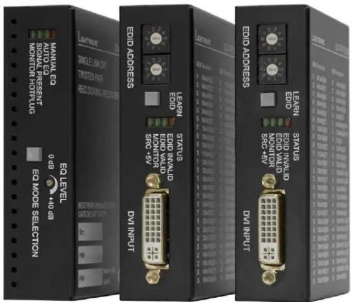
Thank you for choosing Lightware DVI-TP series transmitters and receivers. DVI-TP-TX200/TX300 and DVI-TP-RX100 are Single Link DVI over Twisted Pair extenders which allow video signals of up to 1920x1200@60Hz or 2048x1080@60Hz resolution to be transmitted through 50 meters of high quality CAT7 cables.
2. General description
2.1. Box contents
- DVI-TP-TX200 or DVI-TP-TX300 or DVI-TP-RX100
- User's manual
- Quick Start Guide
- +5V wall plug power adaptor
2.2. Transmitter features (DVI-TP-TX200 and TX300)
- Advanced EDID Management – The user can emulate any EDID on the DVI-TP-TX200/TX300's input, read out and store any monitor's EDID (attached to Monitor Output) in 49 internal memory locations. Green and red EDID status LEDs show whether a valid address is selected.
- Supports all HDTV resolutions – 720p, 1080i and 1080p etc without HDCP encoding. Unencrypted signals with up to 165 MHz pixel clock frequency - regardless of the resolution - are passed through.
- Source and Monitor Connected LEDs – Two LEDs indicate when a DVI source and display device is connected to the DVI-TP-TX200/TX300: the source is sending +5V signal and the display is sending Hot Plug signal.
- Local Monitor Output – The user can attach a local monitor to observe the video signal sent through the CATx cables. The resolution and clock frequency are the same on DVI and RJ45 connector(s), no internal scaling or conversion is applied to the signal.
- Dual CATx outputs (TX300 only) – A built-in distribution amplifier provides the signal for two identical CATx outputs.
- Front panel control – EDID Address selection with two decimal rotary switches and Learn EDID button are available for Advanced EDID Management.
- Fiber cable support – Self powered DVI fiber cables using +5V from DVI sources (VGA cards, etc.) usually consume more than 55 mA, which load is the maximum allowed by DVI 1.0 standard. DVI-TP-TX200/TX300 supports +5V/500 mA constant current output on MONITOR OUTPUT to power fiber optical transmitters.
- Universal power adaptor – DVI-TP-TX200/TX300 is equipped with a universal +5V power adaptor, which accepts AC voltages from 100 to 240 Volts with 50 or 60 Hz line frequency.
2.3. Receiver features (DVI-TP-RX100)
- Input Equalization – The CATx input is compensated for up to 40 dB high frequency cable loss. Automatic and user adjustable modes are available to allow for precise setting of equalization.
- TMDS reclocking – (removes jitter caused by long cables) the DVI OUTPUT has a clean, jitter free signal, eliminating signal instability and distortion caused by long cable or connector reflections.
- Signal Present and Monitor Connected LEDs – Two LEDs indicate when a valid DVI signal is detected and when a display device is connected and it is sending a Hot Plug signal.
- Supports all HDTV resolutions – 720p, 1080i and 1080p etc without HDCP enoding. Unencrypted signals with up to 165 MHz pixel clock frequency - regardless of the resolution - are passed through.
- Front panel control – EQ mode selection button and 25-turn potentiometer are available for precise equalization setting. Red and green LEDs on the front panel indicate the currently selected EQ mode.
- Fiber cable support – Self powered DVI fiber cables using +5V from DVI sources (VGA cards, etc.) usually consume more than 55 mA, which load is the maximum allowed by DVI 1.0 standard. DVI-TP-RX100 supports +5V 500 mA constant current output on DVI OUTPUT to power long distance fiber optical transmitters.
- Universal power adaptor – DVI-TP-RX100 is equipped with a universal +5V power adaptor, which accepts AC voltages from 100 to 240 Volts with 50 or 60 Hz line frequency.
2.4. Understanding EDID
2.4.1. Basics
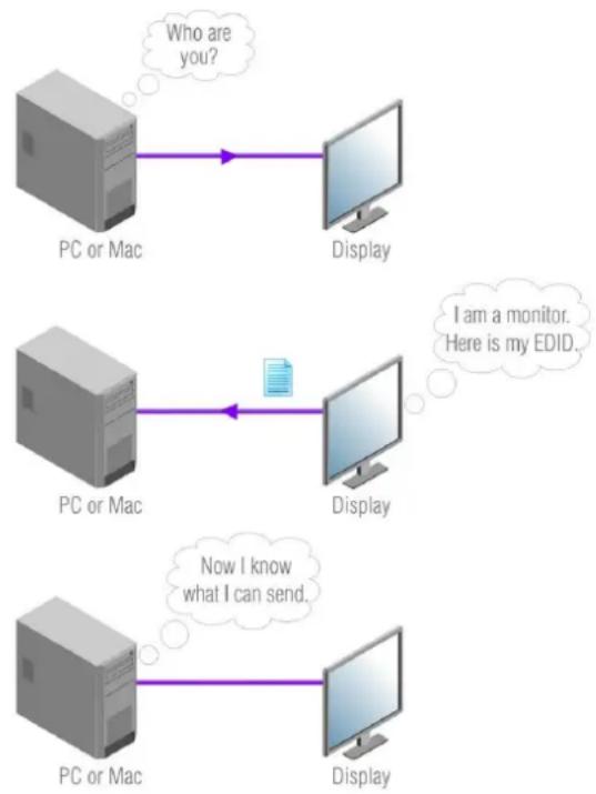
EDID stands for Extended Display Identification Data. Simply put, EDID is the passport of display devices (monitors, TV sets, projectors). It contains information about the display's capabilities, such as supported resolutions, refresh rates (these are called Detailed Timings), the type and manufacturer of the display device, etc.
After connecting a DVI source to a DVI display, the source reads out the EDID to determine the resolution and refresh rate of the image to be transmitted.
flowchart
graph TD
    A["PC or Mac"] -->|Who are you?| B["Display"]
    C["PC or Mac"] -->|I am a monitor. Here is my EDID.| D["Display"]
    E["PC or Mac"] -->|Now I know what I can send.| F["Display"]
Most DVI computer displays have 128-byte long EDID structure. However, Digital Televisions and HDMI capable displays may have another 128 bytes, which is called E-EDID and defined by CEA (Consumer Electronics Association). This extension contains information about additional Detailed Timings, audio capabilities, speaker allocation and HDMI capabilities. It is important to know, that all HDMI capable devices must have CEA extension, but not all devices are HDMI capable which have the extension.
2.4.2. Common problems related to EDID
Problem: "My system consists of the following: a PC, then a Lightware DVI-TP-TX200, a WUXGA (1920x1200) LCD as local monitor, then a DVI-TP-RX100 connected to a SXGA (1280x1024) projector. I would like to see the same image on the monitor and the projector. What EDID should I chose on the DVI-TP-TX200?" (see typical application in section 2.8)
Solution: If you want to see the image on both displays, you need to select the resolution of the smaller display (in this case SXGA), otherwise the smaller display may not show the higher resolution image.
Problem: „I turned the rotary switches on the DVI-TP-TX200/TX300 to have a different resolution but nothing happens.”
Solution: Some graphics cards and video sources read out the EDID only after power-up and later they don't sense that EDID has been changed. You need to restart your source to make it read out the EDID again.
Problem: „I have a DVI-TP-TX200/TX300 and I'm using a Lightware factory preset EDID. I would like to be able to choose from different resolutions, but my source allows only one resolution.”
Solution: Most Lightware factory preset EDIDs allow only one resolution, forcing the sources to output only that particular signal. You need to select the Universal EDID (address 49). It supports all common VESA resolutions. Additionally it also features audio support.
2.5. Advanced EDID Management (DVI-TP-TX200/TX300)
Each DVI sink (e.g. monitors, projectors, plasma displays, and switcher inputs) must support the EDID data structure. Source BIOS and operating systems are likely to query the sink using DDC2B protocol to determine what pixel formats and interface are supported. DVI standard makes use of EDID data structure for the identification of the monitor type and capabilities. Most DVI sources (VGA cards, set top boxes, etc.) will output DVI signal after accepting the connected sink's EDID information. In case of EDID readout failure or missing EDID the source will not output DVI video signal.
DVI-TP-TX200/TX300 provides Lightware's Advanced EDID Management function that helps system integration. It stores and emulates 99 EDIDs plus the EDID of the display device which is connected to MONITOR OUTPUT. Memory addresses from 01 to 50 are factory presets, while memories from 51 to 99 are user programmable. DVI-TP-TX200/TX300 stores the EDID of the monitor or projector connected to Monitor Output in a non-volatile memory.
The EDID emulated on the input can be copied from the DVI-TP-TX200/TX300's memory (static EDID emulation) or from the attached monitor (dynamic EDID emulation). For example, the DVI-TP-TX200/TX300 can be set up to emulate the device, which is connected to MONITOR OUTPUT, and the EDID automatically changes, if the monitor is replaced with another display device (as long as it has a valid EDID).
Info
The user is not required to disconnect the DVI cable to change an EDID as opposed to other manufacturer's products. EDID can be changed even if a source is connected to the input and it is powered ON.
2.6. TMDS Reclocking (DVI-TP-RX100)
DVI-TP-RX100 reclocks the signal on its output using Lightware's sophisticated TMDS Reclocking technology. Signal reclocking is an essentially important procedure in digital signal transmission. After passing the reclocking circuit, the signal becomes stable and jitter-free, and can be transmitted over more equipment like processors and event controllers. When transmitting the signal through long cables without reclocking on the receiver side, sparkles, noise and jaggies can be seen on the image.
Info
TMDS stands for Transition Minimized Differential Signaling. It is the electrical and encoding specification used by the DVI standard to transmit the video signal.
The TMDS Reclocking circuit eliminates the following errors:
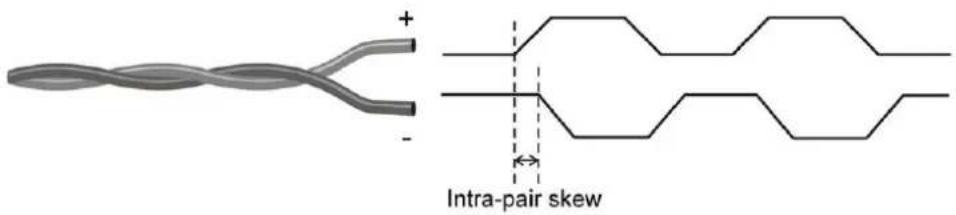
Intra-pair skew: skew between the + and - wires within a differential wire pair (e.g. Data2- and Data2+). It's caused by different wire lengths or slightly different wire construction (impedance mismatch) in DVI cable. It results in jitter.
text_image
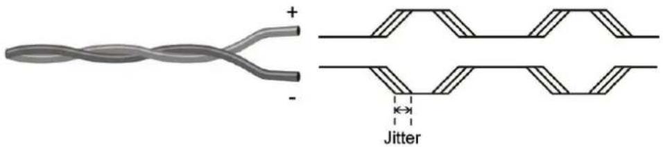
+ - Intra-pair skewJitter: signal instability in the time domain. The time difference between two signal transitions should be a fix value, but noise and other effects cause variations.
text_image
Diagram illustrating a twisted cable with polarity indicators and a jitter symbol, likely from an electronics or signal processing context.Noise: electromagnetic interference between other electronic devices such as mobile phones, motors, etc. and the DVI cable are coupled onto the signal. Too much noise results in increased jitter.

text_image
Diagram illustrating a twisted cable with positive and negative terminals, alongside its corresponding noise waveform diagram.Info
TMDS Recklocking technology does not eliminate more than on bit of Inter-pair skew.
2.7. Fiber Cable powering
As a special feature, DVI-TP-TX200/TX300 (MONITOR OUTPUT) and DVI-TP-RX100 (DVI OUTPUT) are able to supply 500 mA current to power fiber optical transmitters like Lightware DVI-OPT-TX100 (Pin 14 on DVI OUT connector). Standard DVI outputs or VGA cards supply only 55 mA current on +5V output, thus unable to directly power a fiber optical transmitter.
Info DVI-TP-TX200/TX300 and DVI-TP-RX100 do not check if the connected sink (monitor, projector or other equipment) supports Hotplug or EDID signals but output the input signal immediately after it has been applied to the input.
2.8. Applications
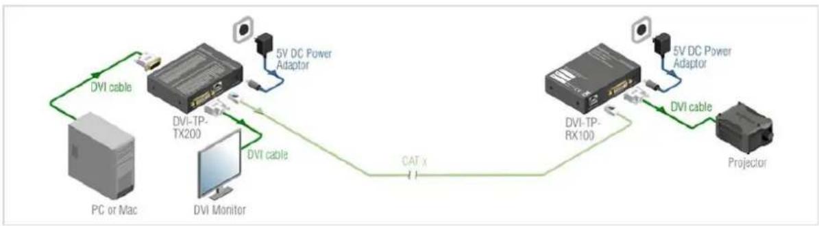
flowchart
graph LR
    A["PC or Mac"] -->|DVI cable| B["DVI-TP-TX200"]
    B -->|DVI cable| C["DVI Monitor"]
    C -->|CATX| D["DVI-TP-RX100"]
    D -->|5V DC Power Adaptor| E["5V DC Power Adaptor"]
    E -->|DVI cable| F["Projector"]
Typical stand-alone application (TX200)
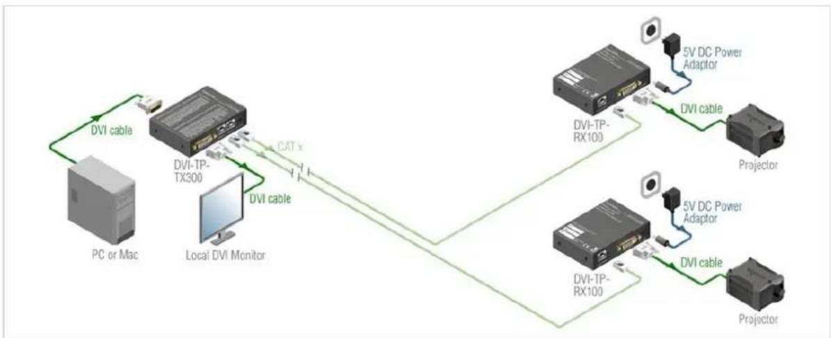
flowchart
graph TD
    A["PC or Mac"] -->|DVI cable| B["DVI-TP-TX300"]
    B -->|CAT x| C["Local DVI Monitor"]
    C -->|DVI cable| B
    B --> D["DVI-TP-RX100"]
    D -->|5V DC Power Adaptor| E["Projector"]
    D --> F["5V DC Power Adaptor"]
    D --> G["5V DC Power Adaptor"]
    D --> H["5V DC Power Adaptor"]
    D --> I["5V DC Power Adaptor"]
Typical stand-alone application (TX300)
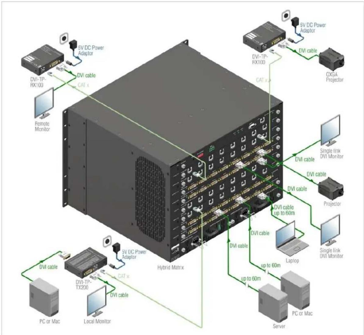
Using with Lightware MX-DVI-FR32R frame
(the frame is equipped with single link DVI-D cards and single link DVI-TP cards)
2.9. Front and rear view
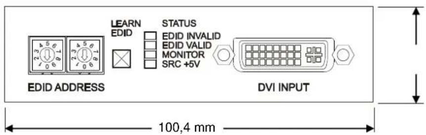
2.9.1. Front view of DVI-TP-TX200/TX300
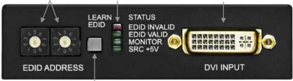
Address selection Status LEDs DVI Input connector
text_image
LEARN EDID STATUS EDID INVALID EDID VALID MONITOR SRC +5V EDID ADDRESS DVI INPUTLearn EDID button
EDID Address
The rotary switches select one of 100 addresses. Addresses 1...50 are factory preset and 51...99 are user programmable. Address 00 enables transparent mode. For more information, see chapter 3.3. Use a flat head screwdriver that fits into the actuator. Avoid the use of keys, coins, knives and other sharp objects because they might cause permanent damage to the rotary switches.
Learn EDID button
Stores the EDID of the display device attached to MONITOR OUTPUT in the selected memory address between 51...99. To learn the EDID, select an appropriate address with the rotary switches and press and hold the Learn button for two seconds.
EDID status LEDs
Function 1: display the firmware version of the device. For more information, see chapter 3.1.
Function 2: after applying a Hot Plug signal to MONITOR OUTPUT, these LEDs indicate that the unit is reading the EDID from the connected display device. If the green LED is blinking then the EDID is valid, if the red LED is blinking, then the EDID is invalid or missing.
Function 3: (main function) these LEDs indicate whether the selected EDID is valid (solid green = valid, solid red = invalid or empty memory selected).
Function 4: after pressing the LEARN button, these LEDs indicate whether the learn process was successful (green blinking = successful, red blinking = unsuccessful). For more information, see chapter 3.2.
Monitor LED
Indicates if a display device (or matrix switcher, repeater, etc.) is connected to the MONITOR OUTPUT connector and sends a valid Hot Plug Signal on Pin 16 through the DVI cable.
SRC +5V LED
Indicates if a DVI source is connected to the DVI-TP-TX200/TX300, it is powered on and sends +5V signal to Pin 14 of the input DVI connector.
DVI Input
Connect one DVI-D or DVI-I cable (only digital pins are connected internally) between the DVI source and DVI-TP-TX200/TX300.
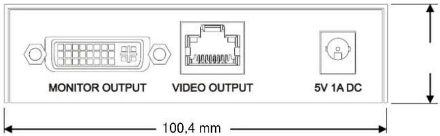
2.9.2. Rear view of DVI-TP-TX200/TX300
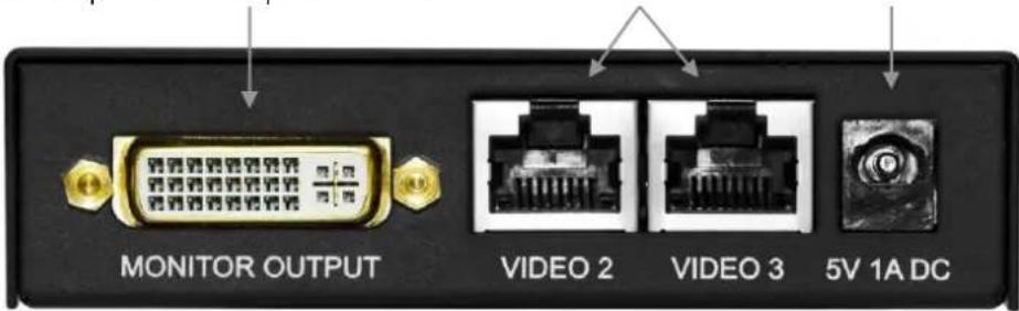
TX200: Local Monitor Output CATx output +5V DC
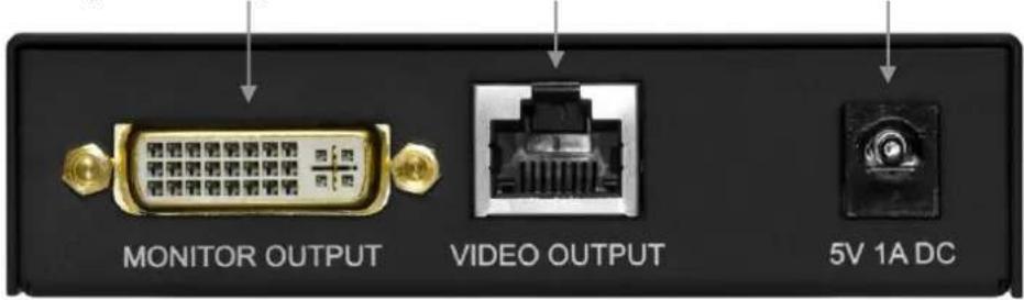
text_image
MONITOR OUTPUT VIDEO OUTPUT 5V 1A DCTX300: Local Monitor Output CATx outputs +5V DC
text_image
MONITOR OUTPUT VIDEO 2 VIDEO 3 5V 1A DCMonitor Output Connect one dual link DVI-D or DVI-I cable (only digital pins are connected internally) between DVI-TP-TX200 and local display device.
The output connector is able to supply 500 mA current on pin 14 to power fiber optical DVI extenders like DVI-OPT-TX100.
If a long DVI cable is connected then equalization and reclocking may be necessary at the receiver end of the cable.
CATx Output(s)
Connect one or two CAT5, CAT5e, CAT6a or CAT7 (recommended) cables between DVI-TP-TX200/TX300 and the receiver (DVI-TP-RX100 or Lightware Hybrid Matrix equipped with twisted pair input cards).
The DVI-TP-TX200/TX300 does not have networking capabilities. Do not connect the RJ45 output(s) of the DVI-TP-TX200/TX300 to a Local Area Network device or a PC. Doing so may damage the unit!
+5V DC connector
Connect the output of the supplied +5V power adaptor. CAUTION! Warranty void if damage occurs due to use of a different power source.
2.9.3. Front view of DVI-TP-RX100
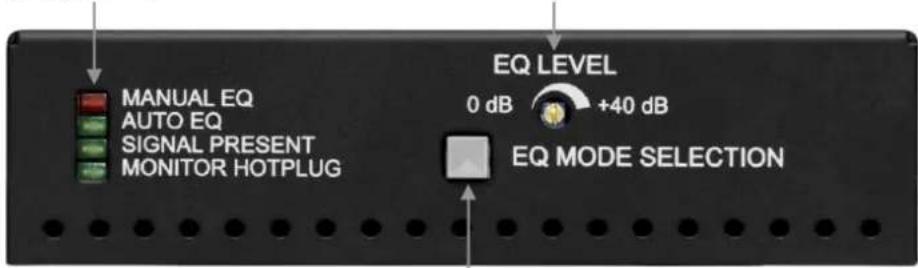
Status LEDs EQ level adjust knob
text_image
MANUAL EQ AUTO EQ SIGNAL PRESENT MONITOR HOTPLUG EQ LEVEL 0 dB +40 dB EQ MODE SELECTIONEQ mode selector button
EQ mode status LEDs Two LEDs indicate whether the DVI-TP-RX100 is in auto or manual equalization mode. Automatic mode usually gives a good result, but at long distances, manual equalization may be necessary. For more information, see chapter 4.2.
Signal Present LED Indicates if a valid DVI clock signal is present on Video Input RJ45 connector.
Monitor Hotplug LED Indicates if a display device (or matrix switcher, repeater, etc.) is connected to the DVI OUTPUT connector and sends a valid Hot Plug Signal on Pin 16 through the DVI cable.
EQ Mode button Toggles between automatic and manual EQ mode. The EQ mode status LEDs indicate which mode is currently active.
EQ level adjust The 25-turn potenciometer can be used to precisely set the right amount of equalization in manual EQ mode. The potenciometer does not stop at the end positions, but rotates indefinitely. After reaching the end position, a clicking sound can be heard at every full turn of the knob.
2.9.4. Rear view of DVI-TP-RX100
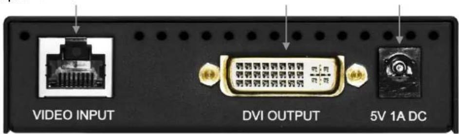
CATx input DVI output +5V DC
text_image
VIDEO INPUT DVI OUTPUT 5V 1A DCCATx input Connect one CAT5, CAT5e, CAT6a or CAT7 (recommended) cables between DVI-TP-RX100 and the transmitter (DVI-TP-TX200/TX300 or Lightware Hybrid Matrix equipped with twisted pair output cards).
The DVI-TP-RX100 does not have networking capabilities. Do not connect the RJ45 input of the DVI-TP-RX100 to a Local Area Network device or a PC. Doing so may damage the unit!
DVI output Connect one DVI-D or DVI-I cable (only digital pins are connected internally) between DVI-TP-RX100 and the display device.
The output connector is able to supply 500 mA current on pin 14 to power fiber optical DVI extenders like DVI-OPT-TX100.
+5V DC connector Connect the output of the supplied +5V power adaptor. CAUTION! Warranty void if damage occurs due to use of a different power source.
2.10. Electrical connections
2.10.1. DVI inputs and outputs
DVI-TP-TX200/TX300 and DVI-TP-RX100 provide 29 pole „digital only” DVI-I connectors for input and output connections. Always use high quality DVI cable for connecting sources and displays.
| Pin | Signal | Pin | Signal | Pin | Signal |
| 1 | TMDS Data2- | 11 | TMDS D1/3 Shield | 21 | TMDS Data5+ (nc) |
| 2 | TMDS Data2+ | 12 | TMDS Data3- (nc) | 22 | TMDS Clk Shield |
| 3 | TMDS D2/4 Shield | 13 | TMDS Data3+ (nc) | 23 | TMDS Clock+ |
| 4 | TMDS Data4- (nc) | 14 | +5V Power | 24 | TMDS Clock- |
| 5 | TMDS Data4+ (nc) | 15 | GND (for +5V) | 25 | R (not connected) |
| 6 | DDC Clock | 16 | Hot Plug Detect | 26 | G (not connected) |
| 7 | DDC Data | 17 | TMDS Data0- | 27 | B (not connected) |
| 8 | VSYNC (nc) | 18 | TMDS Data0+ | 28 | HSYNC (nc) |
| 9 | TMDS Data1- | 19 | TMDS D0/5 Shield | 29 | Analog GND |
| 10 | TMDS Data1+ | 20 | TMDS Data5- (nc) |
Table 1. Single link DVI-I "digital only" connector pin assignment
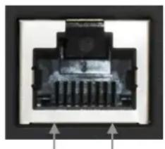
2.10.2. CATx inputs and outputs
DVI-TP-TX200/TX300 and DVI-TP-RX100 are equipped with shielded CAT6 RJ45 connectors.
| Pin | Signal CATx |
| 1 | TMDS Data0+ |
| 2 | TMDS Data0- |
| 3 | TMDS Clock+ |
| 4 | TMDS Data1+ |
| 5 | TMDS Data1- |
| 6 | TMDS Clock- |
| 7 | TMDS Data2+ |
| 8 | TMDS Data2- |
Table 2. RJ45 connector pin assignment
natural_image
Close-up of a black electronic component with internal slots and mounting holes, shown with directional arrows (no text or symbols)Pin 8 Pin 1
3. Operation of DVI-TP-TX200/TX300
3.1. Power
When building an electronic system, make sure that all of the devices are powered down before connecting them. Powered on devices may have dangerous voltage levels that can damage sensitive electronic circuits.
- After the system is complete, connect the output of the +5V Power Adaptor to the DVI-TP-TX200/TX300 (further on TX200/TX300) The unit is immediately powered ON.
- After being powered on, the TX200/TX300 displays its firmware version using the EDID Status LEDs.
The following example shows this process for a firmware version of 1.3.7
RED blinks once → Short pause → GREEN blinks three times → Short pause → GREEN blinks seven times → Short pause → The normal function of the LED is in effect. - After indicating the firmware version, the red EDID status LED lights up for 2-3 seconds, then turns green if the selected EDID is valid, or remains red, if the selected EDID is invalid (or the selected memory is empty).
After the TX200/TX300 is initialized, the attached DVI source and monitor can be powered on. - If a display device is connected to MONITOR OUT, the TX200/TX300 reads the EDID from the attached monitor's EDID memory.
If the read process is successful, the GREEN LED blinks several times then the EDID Status LEDs show whether the selected EDID is valid (green) or not (red) on the DVI INPUT connector.
If the read process is unsuccessful, the RED LED blinks several times then the EDID Status LEDs show whether the selected EDID is valid (green) or not (red) on the DVI INPUT connector.
Info If none of the LEDs light up upon power-up, the unit is most likely damaged and further use is not advised. Please contact support@lightware.hu
3.2. Learning the EDID
The factory preset EDIDs cannot be changed by the user. Only addresses from 51 to 99 are user programmable.
- After connecting the sink device to MONITOR OUT, use a screwdriver to select an empty memory address. EDIDs are stored in a multiple programmable non-volatile memory.
If the red EDID status LED is illuminated, then the memory slot is empty and ready to be programmed. If the green EDID status LED is illuminated, the memory was already used before, but still available for programming.
- Push the LEARN button on the front side of the TX200/TX300 and hold it down for approximately 3 seconds.
Once the button is pushed the EDID status LEDs go dark. If the EDID storing was successful, the green EDID status LED blinks five times and stays illuminated. Now the stored EDID is automatically emulated.
If the storing was unsuccessful, the red EDID status LED blinks five times and either the red or green EDID status LED becomes illuminated, depending on the previous status of the selected EDID address.
3.3. Switching the EDID
- Use a screwdriver to change the memory address on the front side of the TX200/TX300.
After either one of the rotary switches has been rotated, the unit waits approximately 2 seconds before the selected EDID becomes active. If the EDID status is unchanged the EDID status LEDs do not blink, but stay continuously lit.
- The address 00 (zero zero) has a special function. If a monitor is connected to MONITOR OUT, then its EDID is copied to the DVI INPUT connector. If no monitor is connected to the output then the EDID transmitted to the DVI INPUT connector is the EDID of the last connected monitor.
Info If an invalid EDID is selected, the TX200/TX300 does NOT give a HOT PLUG signal to the source connected to DVI INPUT.
Info
After every EDID change, TX200/TX300 toggles the HOT PLUG signal for approx. 1 second. Some graphic cards or DVD players do not sense the HOT PLUG signal, and even if EDID has been changed, the set resolution is not affected. In this case the source device must be restarted, or powered OFF and ON again.
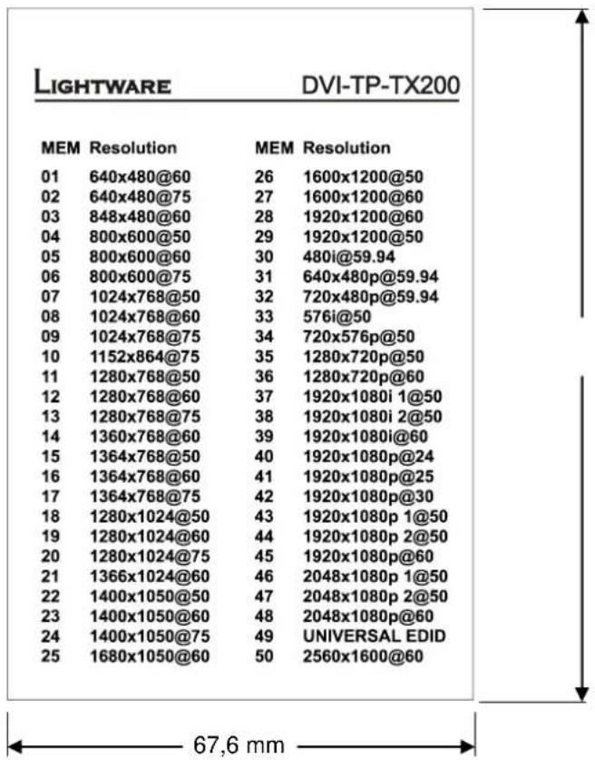
3.4. Factory preset EDID list
Lightware factory pre-loaded EDIDs are specially provided to force graphic cards to output only the exact pixel resolution and refresh rate.
Universal EDID (address 49) allows multiple resolutions including all common VESA defined resolutions. In addition, it also features audio support. The use of universal EDID is recommended for fast and easy system setup.
| MEMORY | Resolution | MEMORY | Resolution | |
| 01 | 640x480@60 Hz | 26 | 1600x1200@50 Hz | |
| 02 | 640x480@75 Hz | 27 | 1600x1200@60 Hz | |
| 03 | 848x480@60 Hz 16:9 | 28 | 1920x1200@60 Hz | |
| 04 | 800x600@50 Hz | 29 | 1920x1200@50 Hz | |
| 05 | 800x600@60 Hz | 30 | 480i@59.94 Hz | |
| 06 | 800x600@75 Hz | 31 | 640x480@59.94 Hz | |
| 07 | 1024x768@50 Hz | 32 | 720x480p@60 Hz | |
| 08 | 1024x768@60 Hz | 33 | 576i@50 Hz | |
| 09 | 1024x768@75 Hz | 34 | 720x576p@50 Hz | |
| 10 | 1152x864@75 Hz | 35 | 1280x720p@50 Hz | |
| 11 | 1280x768@50 Hz | 36 | 1280x720p@60 Hz | |
| 12 | 1280x768@60 Hz | 37 | 1920x1080i1 @50 Hz | |
| 13 | 1280x768@75 Hz | 38 | 1920x1080i2 @50 Hz | |
| 14 | 1360x768@60 Hz | 39 | 1920x1080i@60 Hz | |
| 15 | 1364x768@50 Hz | 40 | 1920x1080p@24 Hz | |
| 16 | 1364x768@60 Hz | 41 | 1920x1080p@25 Hz | |
| 17 | 1364x768@75 Hz | 42 | 1920x1080p@30 Hz | |
| 18 | 1280x1024@50 Hz | 43 | 1920x1080p1 @50 Hz | |
| 19 | 1280x1024@60 Hz | 44 | 1920x1080p2 @50 Hz | |
| 20 | 1280x1024@75 Hz | 45 | 1920x1080p@60 Hz | |
| 21 | 1366x1024@60 Hz | 46 | 2048x1080p1 @50 Hz | |
| 22 | 1400x1050@50 Hz | 47 | 2048x1080p2 @50 Hz | |
| 23 | 1400x1050@60 Hz | 48 | 2048x1080p@60 Hz | |
| 24 | 1400x1050@75 Hz | 49 | UNIVERSAL EDID | |
| 25 | 1680x1050@50 Hz | 50 | 2560x1600@60 Hz |
Table 3. Factory Preset EDID list
4. Operation of DVI-TP-RX100
4.1. Power
When building an electronic system, make sure that all of the devices are powered down before connecting them. Powered on devices may have dangerous voltage levels that can damage sensitive electronic circuits.
- After the system is complete, connect the output of the +5V Power Adaptor to the DVI-TP-RX100 (further on RX100). The unit is immediately powered ON.
- After being powered on, the RX100 displays its firmware version using the EQ mode status LEDs.
The following example shows this process for a firmware version of 1.3.7
RED blinks once → Short pause → GREEN blinks three times → Short pause → GREEN blinks seven times → Short pause → The normal function of the LED is in effect.
- After indicating the firmware version, either the red or green EQ mode status LED stays continuously lit, depending on the last selected mode.
After the RX100 is initialized, the attached monitor can be powered on.
Info If none of the LEDs light up upon power-up, the unit is most likely damaged and further use is not advised. Please contact support@lightware.hu
4.2. Adjusting the input equalization
The amplitude of high frequency signals decreases after they pass through long distances in copper cables. To counter-act this phenomenon, RX100 amplifies the signal while maximizing the amplitude at a certain level, which is defined by the DVI 1.0 standard. This process is called equalization.
The RX100 offers two equalization modes: automatic and manual. Automatic mode usually provides perfect transmission but at longer distances and higher resolutions, manual equalization may be necessary.
- Select the equalization mode by pressing and releasing the EQ mode selection button once. The two EQ mode status LEDs show which mode is currently active.
- Use a 2-3 mm flat head screwdriver to manually adjust the equalization level. Turning the knob clockwise increases the EQ level, turning it counterclockwise decreases the EQ level. The knob of the potentiometer does not stop at the end positions, but rotates indefinitely. After reaching the end position, a clicking sound can be heard at every full turn of the knob.
IMPORTANT! When installing the RX100 in a system, always check which equalization mode is selected, because a previously set manual equalization level may not be suitable for a different system. It is always advised to use the automatic mode and only adjust the equalization manually if the auto mode does not give a good result.
4.3. Maximum twisted pair distances
The following table shows the maximum twisted pair distances. The actual achievable distances may differ, depending on the topology of the whole system. Unshielded Twisted Pair (UTP) cables are susceptible to EMI coming from surrounding devices (cables, mobile phones, motors, etc.). Noisy environments substantially decrease the usable length of unshielded cables. Hence the use of shielded Category 6 cables or Category 7 cables is always recommended. Category 7 cables are screened and foiled by standard.
| Resolution | Vfreq (Hz) | Pixel clk freq. (MHz) | Cat5e UTP | Cat5e FTP | Cat6 UTP | Cat6 FTP | Cat6 S/FTP | Cat7 S/FTP |
| 640x480 | 60 | 25,2 | 60 m | 60 m | 65 m | 70 m | 70 m | 80 m |
| 800x600 | 60 | 40,0 | 60 m | 60 m | 65 m | 65 m | 65 m | 75 m |
| 1024x768 | 60 | 65,0 | 55 m | 55 m | 60 m | 60 m | 60 m | 75 m |
| 1280x720p | 60 | 74,2 | 55 m | 55 m | 60 m | 60 m | 60 m | 70 m |
| 1280x1024 | 60 | 108,0 | 50 m | 50 m | 55 m | 60 m | 60 m | 65 m |
| 1400x1050 | 60 | 121,8 | 45 m | 45 m | 45 m | 55 m | 55 m | 60 m |
| 1600x1200 | 60 | 162,0 | 30 m | 35 m | 35 m | 45 m | 45 m | 50 m |
| 1920x1080p | 60 | 148,5 | 30 m | 35 m | 35 m | 45 m | 45 m | 50 m |
| 1920x1200p | 60 | 153,0 | 30 m | 35 m | 35 m | 45 m | 45 m | 50 m |
Table 4. Maximum twisted pair distances
5. Troubleshooting
5.1. There is no picture
Check the cables
Due to the high data rates, the cables must fit very well. DVI connectors have to be locked with screws, no tensions or breaches are allowed. If your source or display has more connectors then make sure that the proper interface is selected.
Check if the CATx cables are connected properly between the transmitter and receiver.
Check the source equipment
Check the Source Connected LED on the front side of the DVI-TP-TX200/TX300. This LED indicates the presence of the +5V signal coming from the DVI source. If it is not illuminated, then your DVI source is not working properly. Please refer to the user's manual of your DVI source.
If the source is a computer, then verify that the DVI output is selected and active. Try restarting your computer; if you get a picture during the booting process, you have to review the driver settings.
Check the incoming signal
Check the Signal Present LED on the front side of the DVI-TP-RX100. This LED indicates the presence of an active incoming DVI clock signal. If it is not illuminated, then no DVI clock signal is present at the VIDEO INPUT connector.
Make sure that the proper equalization mode is selected and if manual mode is active, the right amount of equalization is set.
Check if there's an outgoing signal on the Monitor Output connector of the DVI-TP-TX200/TX300 (also check the Monitor LED on the front panel). The input signal is always routed to the DVI and RJ45 output connector(s). If there is a signal on the
Monitor Output connector, then the problem is not EDID related. Check if the CATx cables are connected properly.
Check the display status
Check the Monitor Hotplug LED on the front side of the DVI-TP-RX100. This LED indicates the presence of the Hotplug signal coming from the attached display device. If it is not illuminated, then your display is not powered or not configured properly.
Check EDID related problems
Check the EDID Status LEDs on the front side of the DVI-TP-TX200/TX300. These LEDs indicate whether a valid EDID is selected. If the red LED is illuminated, then an invalid EDID or an empty memory address is selected. Please select a valid EDID.
If the green EDID Status LED is illuminated, then maybe your display device is not capable of receiving the sent video format. Try emulating your display device's EDID to the source. You will find help to this process in section 3.3. If you get a picture now, you have an EDID related issue, please read chapter 2.4 for more details.
Check the EDID
Maybe the data rate is too high for that type of cable. Try switching another EDID to the inputs with lower resolution. If the source is a computer and you are an expert user, you can try modifying the refresh rate, so you would be able to get it to work at higher resolutions over a noisy connection.
6. Mechanical Drawings
6.1. DVI-TP-TX200/TX300
6.1.1. Top view
100,4 mm
other
| Memory | Resolution | Value | | :--- | :--- | :--- | | 01 | 640x480@60 | 26 | | 02 | 640x480@75 | 27 | | 03 | 848x480@60 | 28 | | 04 | 800x600@50 | 29 | | 05 | 800x600@60 | 30 | | 06 | 800x600@75 | 31 | | 07 | 1024x768@50 | 32 | | 08 | 1024x768@60 | 33 | | 09 | 1024x768@75 | 34 | | 10 | 1152x864@75 | 35 | | 11 | 1280x768@50 | 36 | | 12 | 1280x768@60 | 37 | | 13 | 1280x768@75 | 38 | | 14 | 1360x768@60 | 39 | | 15 | 1364x768@50 | 40 | | 16 | 1364x768@60 | 41 | | 17 | 1364x768@75 | 42 | | 18 | 1280x1024@50 | 43 | | 19 | 1280x1024@60 | 44 | | 20 | 1280x1024@75 | 45 | | 21 | 1366x1024@60 | 46 | | 22 | 1400x1050@50 | 47 | | 23 | 1400x1050@60 | 48 | | 24 | 1400x1050@75 | 49 | | 25 | 1680x1050@60 | 50 | MEM Resolution MEM Resolution 1600x1200@50 1600x1200@60 1920x1200@60 1920x1200@50 480i@59.94 640x480p@59.94 720x480p@59.94 576i@50 720x576p@50 1280x720p@50 1280x720p@60 1920x1080i 1@50 1920x1080i 2@50 1920x1080i@60 1920x1080p@24 1920x1080p@25 1920x1080p@30 1920x1080p 1@50 1920x1080p 2@50 1920x1080p@60 2048x1080p 1@50 2048x1080p 2@50 2048x1080p@60 UNIVERSAL EDID 2560x1600@60 67,6 mm6.1.2. Front view (controls and input)
26 mm
text_image
LEARN EDID STATUS EDID INVALID EDID VALID MONITOR SRC +5V EDID ADDRESS DVI INPUT 100,4 mm6.1.3. Rear view (outputs and power)
26 mm
text_image
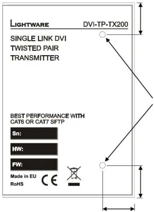
MONITOR OUTPUT VIDEO OUTPUT 5V 1A DC 100,4 mm6.1.4. Bottom view
16.4 mm
text_image
LIGHTWARE DVI-TP-TX200 SINGLE LINK DVI TWISTED PAIR TRANSMITTER BEST PERFORMANCE WITH CAT6 OR CAT7 SFTP Sn: HW: FW: Made in EU RoHS CE2x M3 thread
16.5 mm
16,4 mm
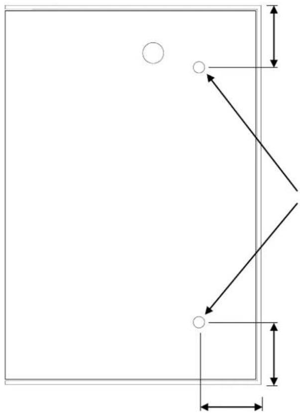
For rack mounting, cross recessed M3 (max. 10 mm long) screws must be used.
6.2. DVI-TP-RX100
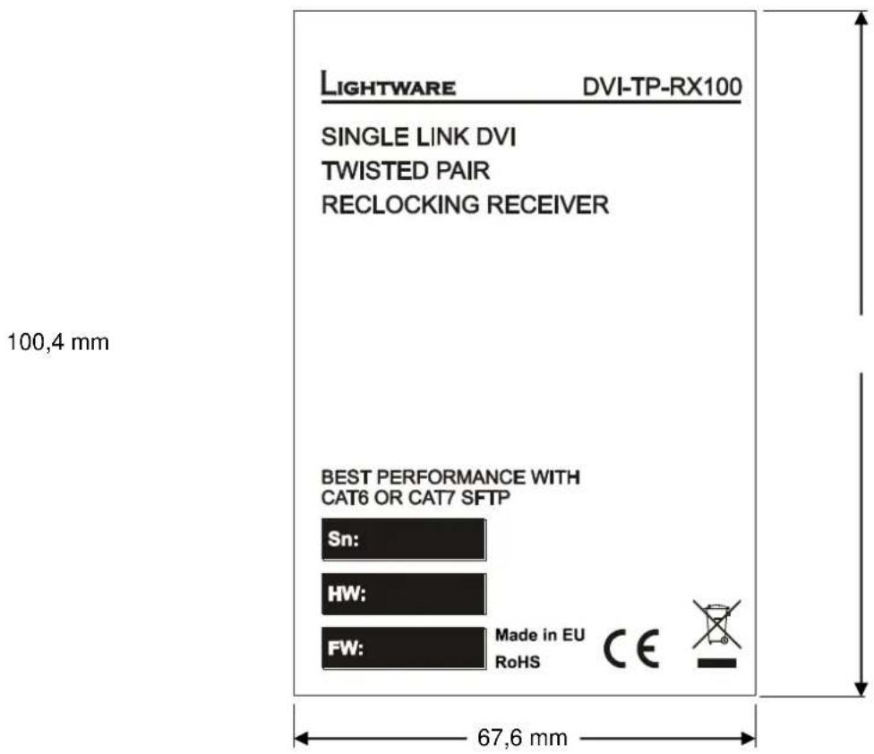
6.2.1. Top view
text_image
LIGHTWARE DVI-TP-RX100 SINGLE LINK DVI TWISTED PAIR RECLOCKING RECEIVER BEST PERFORMANCE WITH CAT6 OR CAT7 SFTP Sn: HW: FW: Made in EU RoHS CE6.2.2. Front view (controls)
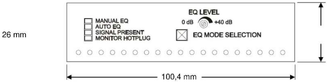
text_image
26 mm MANUAL EQ AUTO EQ SIGNAL PRESENT MONITOR HOTPLUG EQ LEVEL 0 dB +40 dB EQ MODE SELECTION 100,4 mm6.2.3. Rear view (inputs, output and power)
26 mm
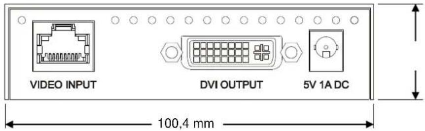
text_image
VIDEO INPUT DVI OUTPUT 5V 1A DC 100,4 mm6.2.1. Bottom view
16.4 mm
2x M3 thread
16.5 mm
16,4 mm
natural_image
Pure geometric diagram with lines and circles, no text or symbols presentFor rack mounting, cross recessed M3 (max. 10 mm long) screws must be used.
7. Specifications
Video
Standard ...... DVI 1.0
Color depth 24 bits, 8 bit/color
Format ...... RGB only
Data rate...... all between 25 Mbps and 1.65 Gbps /TMDS channel
Resolutions...... all between 640x480 and 1920x1200@60Hz
HDTV resolutions ....720p, 1080i, 1080p
HDCP compliant .... No
Input equalization (RX100)....+40 dB, automatic, manual
Reclocking (RX100)....TMDS Reclocking
EDID Emulation (TX200/TX300) .. Yes, 50 factory preset, 50 user programmable
EDID Support (TX200/TX300)...... 256 Byte Extended EDID
General
Connectors 29-pole DVI-I digital only, CAT6 RJ45
Number of DVI inputs ....1 single link
Number of CATx inputs (RX100)....1 single link
Number of CATx outputs (TX200)....1 single link
Number of CATx outputs (TX300)....2 single link
+5V output current (DVI) .....500 mA continuous with overcurrent protection
Power adaptor ....100-240 V AC 50/60 Hz 0.6A to +5V DC 2.6A
Power consumption (TX200/TX300) 4 W typical
6 W max when powering a fiber extender on DVI output
Power consumption (RX100)....3 W typical
6 W max when powering a fiber extender on DVI output
Compliance......CE
EMI/EMC EN 55022 Class B
Safety....UL, CUL, GS, CR, RCM, PSE, Class II
Warranty ....3 years
Enclosure
Rack mountable.... Yes
Material .... 1 mm Metal
Dimensions....100,4 mm W x 67,6 mm D x 26 mm H
Net Weight (TX200 and RX100).... 230 g
Net Weight (TX300) 240 g
8. Warranty
Lightware Visual Engineering warrants this product against defects in materials and workmanship for a period of three years from the date of purchase.
The customer shall pay shipping charges when unit is returned for repair. Lightware will cover shipping charges for return shipments to customers.
In case of defect please contact your local representative, or Lightware at
Lightware Visual Engineering
H-1071 Budapest, Peterdy Street 15, HUNGARY
E-mail: support@lightware.eu
9. Document revision history
| Document | Release Date | Changes | Editor |
| Rev. 1.0 | 22-07-2010 | Initial version | Tibor Fejes |
| Rev. 1.1 | 12-15-2015 | Safety instructions updated, CE page pulled out | Laszlo Zsedenyi |