UMX-OPT-TX150R - Audio/video extender Lightware - Free user manual and instructions
Find the device manual for free UMX-OPT-TX150R Lightware in PDF.


User questions about UMX-OPT-TX150R Lightware
0 question about this device. Answer the ones you know or ask your own.
Ask a new question about this device
Download the instructions for your Audio/video extender in PDF format for free! Find your manual UMX-OPT-TX150R - Lightware and take your electronic device back in hand. On this page are published all the documents necessary for the use of your device. UMX-OPT-TX150R by Lightware.
USER MANUAL UMX-OPT-TX150R Lightware
UMX-OPT-TX150R - User's Manual 2
Important Safety Instructions
Class II apparatus construction.
The equipment should be operated only from the power source indicated on the product.
To disconnect the equipment safely from power, remove the power cord from the rear of the equipment, or from the power source. The MAINS plug is used as the disconnect device, the disconnect device shall remain readily operable.
There are no user-serviceable parts inside of the unit. Removal of the cover will expose dangerous voltages. To avoid personal injury, do not remove the cover. Do not operate the unit without the cover installed.
The appliance must be safely connected to multimedia systems. Follow instructions described in this manual.qqqq

CAUTION AVS
RISK OF ELECTRIC SHOCK
DO NOT OPEN
RISQUE DE CHOC ELECTRIQUE NE PAS OLVID
NE PAS OUVRIR

Ventilation
For the correct ventilation and to avoid overheating ensure enough free space around the appliance. Do not cover the appliance, let the ventilation holes free and never block or bypass the ventilators (if any).
WARNING
To prevent injury, the apparatus is recommended to securely attach to the floor/wall or mount in accordance with the installation instructions. The apparatus shall not be exposed to dripping or splashing and that no objects filled with liquids, such as vases, shall be placed on the apparatus. No naked flame sources, such as lighted candles, should be placed on the apparatus.
Waste Electrical & Electronic Equipment WEEE
This marking shown on the product or its literature, indicates that it should not be disposed with other household wastes at the end of its working life. To prevent possible harm to the environment or human health from uncontrolled waste disposal, please separate this from other types of wastes and recycle it responsibly to promote the sustainable reuse of material resources. Household users should contact either the retailer where they purchased this product, or their local government office, for details of where and how they can take this item for environmentally safe recycling. Business users should contact their supplier and check the terms and conditions of the purchase contract. This product should not be mixed with other commercial wastes for disposal.
Caution: Laser product


Common Safety Symbols

| Symbol Description | |
| — — — | Direct current |
| ~ | Alternating current |
| Double insulation | |
| Caution, possibility of eletric shock | |
| Caution | |
| Laser radiation | |


UMX-OPT-TX150R - User's Manual 3
Symbol Legend
The following symbols and markings are used in the document:
WARNING! Safety-related information which is highly recommended to read and keep in every case!
ATTENTION! Useful information to perform a successful procedure; it is recommended to read.
INFO: A notice which may contain additional information. Procedure can be successful without reading it.
TIPS AND TRICKS: Ideas which you may have not known yet but can be useful.
Navigation Buttons

Go back to the previous page. If you clicked on a link previously, you can go back to the source page by the button.

Navigate to the Table Contents.

Step back one page.

Step forward to the next page.
Document Information
This User's Manual applies to the following versions of the mentioned software, firmware, and hardware:
| Item Version | |
| Lightware Device Controller (LDC) software | 1.14.0b3 |
| Lightware Device Updater (LDU) software | 1.3.4b4 |
| Controller firmware | 1.0.4 |
| Hardware | 1.1 |
Document revision: 3.0
Release date: 01-09-2017
Editor: Judit Barsony
Table of Contents
- INTRODUCTION 6
1.1.DESCRIPTION....6
1.2. BOX CONTENTS 6
1.3. COMPATIBLE DEVICES 6
1.4 FEATURES OF THE DEVICE....7
1.5. TYPICAL APPLICATION 8 - INSTALLATION....9
2.1.MOUNTING OPTIONS 9
2.2. CONNECTING STEPS....10
2.3. CONNECTION OF SERIAL DEVICES ....10
2.3.1. GENERAL INFORMATION....10
2.3.2. Types of Serial Cables....11
2.3.3. CONNECTION DIAGRAM - EXAMPLES....11
2.3.4. Connecting Serial Devices 11 - PRODUCT OVERVIEW 12
3.1. UMX-OPT-TX150R - FRONT VIEW 12
3.2. UMX-OPT-TX150R - REAR VIEW 13
3.3. ELECTRICAL CONNECTORS....14
3.3.1. DVI-I Input 14
3.3.2. VGA Input 14
3.3.3.HDMI Input 14
3.3.4. Fiber Optical Output 14
3.3.5. Analog Audio Input 14
3.3.6.S/PDIF Input 14
3.3.7. BS-232 Port 14
3.3.8 USB Connector 14
3.3.9. DC 5V Connection 14
3.4. PORT DIAGRAM 15 - OPERATION OF UMX-OPT-TX150R....16
4.1. BOOT UP OF UMX-OPT-TX150R 16
4.1.1. Firmware Indication.... 16
4.2. FRONT PANEL LEDs 16
4.3. REAR PANEL LEDs 17
4.4. INPUT SELECTION 17
4.4.1. Video Input Selection 17
4.4.2. Audio Input Selection 17
4.5. VIDEO AUTOSELECT MODE....17
4.5.1. Non-Priority (First Detect) 17
4.5.2. HDMI Digital Priority 18
4.5.3. DVI-D Digital Priority 18
4.6. AUDIO AUTOSELECT MODE....18
4.6.1. Static Select 18
4.6.2. Non-Priority (First Detect) 18
4.6.3. Priority Detect 19
4.6.4. Fix Selection....19
4.7. EDID MANAGEMENT....19
4.7.1. EDID Memory Structure 20
4.7.2. Deleting the EDID....21
4.7.3. EDID Types 21
4.7.4. EDID Learning 22
4.7.5. EDID Switching 22
4.8. HDCP MANAGEMENT 22
4.9. RELOAD FACTORY DEFAULTS....22
4.10. SERVICE MENU 23
4.10.1. Enter the Service Menu of UMX-OPT-TX150R 23
4.10.2. Service Menu Display and Navigation....23
4.10.3. Saving in the Service Menu 24
4.10.4. Exit from Service Menu 24
4.11. REMOTE OPERATION 24
4.11.1. Control Interfaces 24
4.11.2. Multiple Simultaneous Connections....24
4.11.3. RS-232 Operation Modes 24
- SOFTWARE CONTROL - LIGHTWARE DEVICE CONTROLLER ...26
5.1. INSTALL AND UPGRADE 26
5.2 ESTABLISHING THE CONNECTION 27
5.3. CROSSPOINT MENU 27
5.4 INPUT PARAMETERS SETTINGS WINDOW 28
5.4.1 Reload Factory Defaults 28
5.4.2 General Settings 28
5.4.3 Input Port Status 28
5.4.4 Video Signal Info 28
5.4.5 Audio Signal Info 28
5.4.6 Analog Video Options 28
5.4.7 Frame Detector 29
5.5. OUTPUT PARAMETERS SETTINGS WINDOW 30
5.5.1. Set Signal Properties 30
5.5.2 General 30
5.5.3. Display 30
5.5.4. SUPPORTED AUDIO FORMATS....30
5.5.5. Autoselect Settings 30
5.5.6. Optical Module Properties 30
5.6. EDID MENU....31
5.6.1. EDID Operations....31
5.6.2. EDID Summary Window 32
5.6.3. Editing an EDID 32
5.6.4. Creating an EDID 33
5.7. SETTINGS MENU....33
5.7.1. DEVICE INFORMATION....33
5.7.2. Status 33
5.7.3. Log....33
5.8. TERMINAL WINDOW....34
6. LW2 PROGRAMMERS' REFERENCE....35
6.1. SERIAL PORT SETTINGS....35
6.2. LW2 PROTOCOL DESCRIPTION....35
6.3. STATUS AND IDENTIFICATION COMMANDS....36
6.3.1 View Product Type 36
6.3.2 View Serial Number 36
6.3.3 View Firmware Version of the CPU 36
6.3.4 View Installed Controllers' Firmware 36
6.3.5 View Device's Temperature 36
6.3.6 View CPU Firmware Compile Time 36
6.3.7 View Installed I/O Boards 36
6.3.8 Query All Port Status 37
6.4. SYSTEM COMMANDS....37
6.4.1 Query Current Control Protocol 37
6.4.2 Change RS-232 Baud Rate 37
6.4.3 Query RS-232 Baud Rate 37
6.4.4 Reload Factory Defaults 38
6.4.5 Set the RS-232 Operation Mode 38
6.4.6 Query the RS-232 Operation Mode 38
6.4.7 Clear HDCP Key Cache 38
6.4.8 Count HDCP Keys 39
6.4.9 Restart Transmitter 30
6.4.10 View Error List 39
6.4.13. View Error List.... 6.9
6.4.11. Configure Remote Alerts 40
6.4.12 Query Level of Remote Alerts 40
6.4.13 Set the Video Priority Settings 40
6.4.14. Query the Video Priority Settings 40
6.4.15 Set the Audio Priority Settings 41
6.4.16. Query the Audio Priority Settings 41
6.5 EDID ROUTER COMMANDS 41
6.5.1 Save EDID to User Memory (Learn EDID) 41
6.5.2 View Emulated EDIDs on All Inputs 41
6.5.2. View Emulated EDIs on All Inputs 41


UMX-OPT-TX150R - User's Manual 5
6.5.3. Watch EDID Validity Table 41
6.5.4. View EDID Header 42
6.5.5. Download EDID Content from the Transmitter 42
6.5.6. Upload EDID Content from the Transmitter 42
6.5.7. Delete EDID from Memory 43
6.6. CONTROL COMMANDS....43
6.6.1. Switch One Input to One Output 43
6.6.2. View All Connections on the Output 44
6.6.3. Query Autoselect State 44
6.7. ERROR LOG RELATED COMMANDS....44
6.7.1. List a Directory....44
6.7.2. List the Log File 44
6.7.3. Clear the Log File 44
6.8. INPUT PROPERTIES 45
6.8.1. Set Input Port Properties 45
6.8.2. Query Input Port Properties 46
6.8.3. Set Analog Timing Properties 47
6.8.4. Query Analog Timing Properties 47
6.8.5. Reset Analog Timing Properties 47
6.8.6. Set Analog Color Properties 47
6.8.7. Save Analog Color Properties 48
6.8.B. Query Analog Color Properties 48
6.8.9. Reset Analog Color Properties 48
6.8.10. Set Analog Input Audio Parameters 48
6.8.11. Query Analog Input Audio Properties 48
6.8.12. Set the No Sync Picture Properties 49
6.8.13. Query the No Sync Picture Properties 49
6.8.14. Query Timings of the Incoming Signal 49
6.8.15. Save Preset 50
6.8.16. Delete Preset 50
6.8.17. Delete All Presets 50
6.8.18. Clone Preset 50
6.8.19. List Presets 50
6.8.20. Delete Preset from All Input Ports.... 51
6.9. OUTPUT PROPERTIES....51
6.9.1. Set Output Video Properties 51
6.9.2. Query Output Video Properties 52
6.10. ERROR RESPONSES 52
6.11. LW2 COMMANDS - QUICK SUMMARY 52
7. FIRMWARE UPGRADE 54
7.1. INSTALL AND UPGRADE 54
7.1.1. Establish the Connection 55
7.1.2. Start the LDU and Follow the Instructions 55
-
TROUBLESHOOTING....58
-
TECHNOLOGIES....59
9.1. EDID MANAGEMENT....59
9.1.1. Understanding the EDID 59
9.1.2. Advanced EDID Management 59
9.2. HDCP MANAGEMENT 60
9.2.1. Protected and Unprotected Content 60
9.2.2. Disable Unnecessary Encryption 60
9.3. PIXEL ACCURATE RECLOCKING 60
- APPENDIX 61
10.1. SPECIFICATION....61
10.2. FACTORY DEFAULT SETTINGS....62
10.3. FACTORY EDID LIST 63
10.4. MECHANICAL DRAWINGS 64
10.5.ASCI TABLE 64
10.6. FURTHER INFORMATION....65
1
Introduction
Thank You for choosing Lightware UMX-OPT-TX150R monitor extender. The product is an all-round, universal video and audio transmitter for ever-changing environments such as small board and conference rooms. The extender was designed to handle digital and analog video and audio signals e.g. VGA, YPbPr, DVI and HDMI 1.3 with analog stereo, 5.1 S/PDIF and even 7.1 HDMI embedded audio.
In this first chapter of this manual we would like to introduce the device highlighting the most important features in the below listed sections:
DESCRIPTION
Box CONTENTS
COMPATIBLE DEVICES
FEATURES OF THE DEVICE
TYPICAL APPLICATION
1.1. Description
Lightware's UMX-OPT-TX150R is a universal video and audio transmitter. It was designed to handle digital and analog signals for both video and audio e.g. VGA, DVI and HDMI 1.3 with analog stereo, 5.1 S/PDIF and even 7.1 HDMI embedded audio.
Analog signals are converted to digital Formats with digital or digitized analog audio becoming embedded in the video stream. The UMX-OPT-TX150R handles HDCP encryption and has an HDCP enable/disable function.
Using factory, custom or transparent EDID emulation (separate rotary switches for VGA, DVI-A, DVI-D and HDMI inputs), the user can fix and lock EDID data on the transmitter's input connector. Advanced EDID Management forces the required resolution from any VGA or HDMI laptop and fixes the output Format conforming to the system requirement.
Control options available through RS-232: The UMX-OPT-TX150R can be controlled from either a touch controller or a control system. The transmitter has an RS-232 pass-through option which allows direct bidirectional communication between the touch controller and control system. For advanced users RS-232 baud rate can be manually configured by a rotary switch as well as by the control software.
Model Denomination
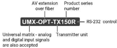
text_image
AV extension over fiber Product series number UMX-OPT-TX150R RS-232 control Universal matrix - analog and digital input signals are also accepted Transmitter unit1.2. Box Contents

text_image
UMX-DPT-TX150R Transmitter Unit 5V DC adaptor with interchangeable plugs Safety & warranty Info, Quick Start Guide1.3. Compatible Devices
Cross compatibility between all the devices in the product series is ensured thanks to Lightware's attentive design. The transmitter can be paired with any receiver without restriction. With Lightware's Hybrid Modular Matrix concept, it is even possible to connect the UMX-OPT-TX150R directly to the matrix router using an MX-HDMI-OPT or MX-DVI-OPT series input board. You can see the list of compatible devices below:
| Product name Product group | |
| DVIDL-OPT-RX100 DVIDL-OPT series | |
| DVI-OPT-RX110 DVI-OPT-110 series | |
| DVI-OPT-RX220-Pro DVI-OPT-220 series | |
| HDMI 3D-OPT-RX150RA HDMI 3D-OPT series | |
| HDMI-OPT-RX100 HDMI-OPT series | |
| HDMI-OPT-RX100R HDMI-OPT series | |
| HDMI-OPT-RX200R HDMI-OPT series | |
| MX-DVI-OPT-IB | MX Boards |
| MX-HDMI-OPT-IB | MX Boards |
1.4. Features of the Device

HDCP Compliant
UMX-OPT-TX150R complies with HDCP standard Lightware is a legal HDCP adopter. Both HDCP-encrypted and non-HDCP components can be installed in the same system. The included advanced HDCP management eliminates the need for re authentication upon switching.

Zero Frame Delay
Even on Analog Inputs - Lightware's UMX-OPT-TX150R add no frame noticeable delay to the switched signal. There is no frame or line period delays to the signals when passing a Lightware device.

Advanced EDID Management
The user can emulate any EDID on the inputs independently, read out and store any attached monitor's EDID in 100 internal memory locations, upload and download EDID files using Lightware Device Controller software.

20 meters Input Cable Compensation
Using 22AWG high quality DVI or HDMI cable, the digital inputs are automatically compensated for up to 20 meters cable length at 24bpp, which extends installation possibilities even at the highest HDTV or computer resolutions.

Supports all HDTV Resolutions
720p, 1080i, 1080p 2K etc. HDTV signals up to 225 MHz pixel clock frequency are passed through regardless of the resolution.

Pixel Accurate Reclocking
Each output has a clean, jitter free signal, eliminating signal instability and distortion caused by long cables or connector reflections.

Frame Detector and Signal Analysis
The exact video and audio signal Format can determined such as timing, frequencies, scan mode, HDCP encryption, color range, color space and audio sample rate.

Universal Power Adaptor
UMX-OPT-TX150R transmitter is equipped with a universal +5V DC power adaptor, which accepts AC voltages from 100 to 240 Volts with 50 or 60 Hz line frequency.

Separate Audio and Video Switching
Video and audio signals are separated and can be switched independently. Even if the HDMI stream contains embedded audio.

Analog Audio and Video A/D Conversion
UMX-OPT-TX150R converts uncompressed analog audio and video signal to digital and places it to the output.

Analog and Digital Audio Embedding
Accepts analog stereo; 5.1 S/PDIF and even 7.1 HDMI embedded audio signals. Analog signals are converted to digital Formats and digital or digitized analog audio can be embedded in the video stream.

Autoswitch Function for Video and Audio Inputs
Autoselect mode with or without priority can toggles between inputs. It helps the handling of the transmitter and installation of new devices.

Single Fiber Technology
All of the high-speed TMDS data lanes are transmitted using only one multimode 50/125 (or 62.5/125) fiber optical cable.

USB Control
Input status, Advanced EDID Management, Terminal Window and hardware information can be accessed with Lightware Device Controller software via USB connection.

Bidirectional RS-232 and Control
Input status, Advanced EDID Management, Terminal Window and hardware information can be accessed with Lightware Device Controller software via simple ASCII-based RS-232 protocol. Serial port passthrough supports any third-party unit that works with standard RS-232.


- Introduction UMX-OPT-TX150R - User's Manual 8
1.5. Typical Application
The typical application of the UMX-OPT-TX150R transmitter:
• Executive boardrooms
- Small classrooms
• Conference rooms, collaborative telepresence
- Multiroom video and audio control
• Home theatre systems
Standalone Application
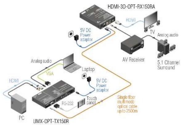
flowchart
graph TD
    A["PC"] -->|Analog audio| B["UMX-CPT-TX150R"]
    B -->|VGA| C["PG"]
    B -->|Laptop| D["5V DC Power adapter"]
    D --> E["AV Receiver"]
    E --> F["TV"]
    F --> G["Analog audio"]
    G --> H["5.1 Channel Surround"]
    B --> I["Touch panel"]
    I --> J["PG-232"]
    J --> K["5V DC Power adapter"]
    K --> L["HDMI-3D-OPT-RX150RA"]
    style A fill:#f9f,stroke:#333
    style B fill:#ccf,stroke:#333
    style C fill:#cfc,stroke:#333
    style D fill:#fcc,stroke:#333
    style E fill:#cff,stroke:#333
    style F fill:#ffc,stroke:#333
    style G fill:#fcc,stroke:#333
    style H fill:#ffc,stroke:#333
    style I fill:#cfc,stroke:#333
    style J fill:#cfc,stroke:#333
    style K fill:#cfc,stroke:#333
    style L fill:#fcc,stroke:#333
Integrated System Application
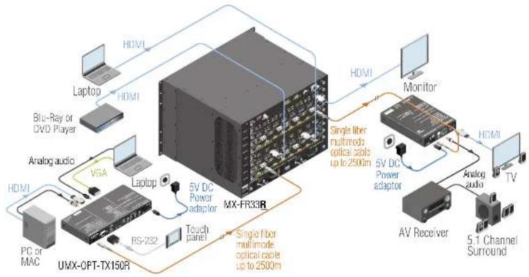
flowchart
graph TD
    A["PC or MAC"] --> B["UMX-OPT-TX150R"]
    C["Laptop"] --> D["5V DC Power adaptor"]
    E["Laptop"] --> D
    F["Blu-Ray or DVD Player"] --> D
    G["Analog audio"] --> H["VGA"]
    I["PC"] --> J["RS-232"]
    K["Touch panel"] --> L["Single fiber multimode optical cable up to 2500m"]
    M["HDMI"] --> N["Monitor"]
    O["5V DC Power adaptor"] --> P["Analog audio"]
    Q["AV Receiver"] --> R["5.1 Channel Surround"]
    S["Monitor"] --> T["5V DC Power adaptor"]
    U["Analog audio"] --> V["5.1 Channel Surround"]
2
Installation
The chapter is about the installation of the device and connecting to other appliances, presenting also the mounting options and further assembly steps:
MOUNTING OPTIONS
CONNECTING STEPS
▶ CONNECTION OF SERIAL DEVICES
2.1. Mounting Options
To mount the extender Lightware supplies optional accessories for different usage. There are two kinds of mounting kits with similar fixing method. The device has two mounting holes with inner thread on the bottom side; see the bottom view in Mechanical Drawings section. Fasten the device by the screws enclosed to the accessory.
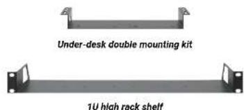
text_image
Under-desk double mounting kit 1U high rack shelfThe Under-desk double mounting kit makes easy to mount a single device on any flat surface, e.g. furniture. 1U high rack shelf provides mounting holes for fastening two half-rack or four quarter-rack sized units. Pocket-sized devices can also be fastened on the shelf. To order mounting accessories please contact sales@lightware.eu.
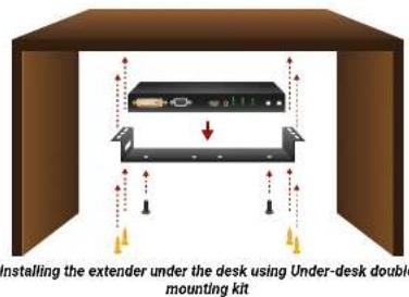
text_image
Installing the extender under the desk using Under-desk double mounting kitINFO: The chipboard screws are not supplied with the mounting kit.
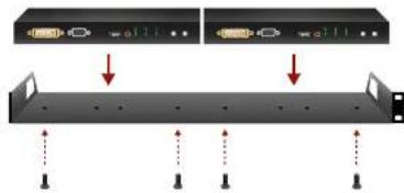
natural_image
Diagram of a server rack with two monitors and mounting points, showing no text or symbolsMounting of two extenders to a 1U high rack shelf
WARNING! Always use the supplied screws. Using different (e.g. longer) ones may cause damage to the device.
ATTENTION! Always use all the four screws for fixing the rack shelf ears to the rack rail. Choose properly sized screws for mounting. Keep minimum two threads left after the nut screw.
INFO: The extender is half-rack sized.
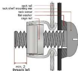
text_image
rack shell mounting rod rack screw flat washer cage nut min. 2 threads leftMounting 1U high rack shelf to the rack rail
2.2. Connecting Steps
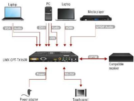
flowchart
graph TD
    A["Laptop"] -->|VGA Audio| B["LVX OPT-TX150R"]
    C["PC"] -->|DV-1 Audio| B
    D["Laptop"] -->|HDMI Audio| B
    E["Mocia player"] -->|S/PDIF Audio| B
    B -->|USB| F["Switch"]
    F --> G["RS-232"]
    G --> H["Power adaptor"]
    G --> I["Touch panel"]
    J["Compatible receiver"] --> K["OPTM"]
    K --> F
| VGA | Connect the transmitter and the sources using the proper VGA / DVI-H / HDMI cables. |
| OVI | |
| HDMI | |
| Audio | Optionally connect an audio device (e.g. the VGA laptop) to the audio input port. |
| S/PDIF Audio | Optionally connect a digital audio device (e.g. the Media player) to the S/PDIF audio input port. |
| USB | Optionally connect a USB A - Mini USB B cable between the transmitter unit and the computer in order to control the device. |
| OPTM | Connect a multimode (OPTM) fiber cable to the SC fiber output port of the transmitter to the SC fiber input port of the compatible receiver. See the list of the Compatible Devices. |
| RS-232 | Optionally for RS-232 control: connect a controller/ controlled device (e.g. Touch panel) to the RS-232 port. |
| Power | Firstly connect the power adaptor to the DC input of the transmitter, then to the AC power socket. |
WARNING! Please do not look directly into the SC fiber optical connector if the cable is connected to the transmitter only and the laser is active. INFO: Powering the devices on is recommended to do as the final step during the installation.
2.3. Connection of Serial Devices
2.3.1. General Information
There are two types of devices in general serial communication:
- Data Terminal Equipment: Data Terminal Equipment (DTE) is an end instrument that converts user information into signals or reconverts received signals. Typical DTE devices: computers, LCD touch panels and control systems.
- Data Circuit-terminating Equipment: Data Circuit-terminating Equipment (DCE) is a device that sits between the DTE and a data transmission circuit. It is also called data communication equipment and data carrier equipment. Typical DCE devices: projectors, industrial monitors and amplifiers.
Among others the pin assignment is different between DTE and DCE.
| DTE DCE | ||
| Pin 2: | RD TD | |
| Pin 3: | TD RD | |
RD: Received Data (digital input)
TD: Transmitted Data (digital output)
INFO: UMX-OPT-TX150R is DCE unit according to its pin-out.
Different type of serial cables must be used between different serial devices.
| DTE | DCE | |
| DTE | Null-modem | TD |
| DCE | Straight | Null-modem* |
* In general contact DCE with DCE by tail-circuit serial cable.


- Installation UMX-OPT-TX150R - User's Manual 11
2.3.2. Types of Serial Cables
Straight Serial Cable
Straight pin-outs both ends.
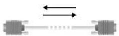
Null-modem Serial Cable
Straight pin-out at the one end and cross pin-out at the other end (interchange lines of TX and RX). For the detailed RS-232 connector pinout see RS-232 Port section.
Serial cables between devices may have male or female plugs and their type may be straight or null-modem in usual.
ATTENTION! The cable type does not depend on the plug type.
Connection Diagram - Examples
The following cases are Examples. Devices may have different receptacles and pinouts.
Extending RS-232 between Controller System (DTE) and Projector (DCE)
Connect straight serial cable between controller system (DTE) and the transmitter (DCE) and straight serial cable between receiver (DTE) and projector (DCE).
Controller
system Projector

flowchart
graph LR
    A["RS-232 DTE\nPin 2: RD\nPin 3: TD"] --> B["TX"]
    B --> C["RX"]
    C --> D["RS-232 DCE\nPin 2: TD\nPin 3: RD"]
    B -->|OPT cable| C
    style A fill:#f9f,stroke:#333
    style B fill:#ccf,stroke:#333
    style C fill:#cfc,stroke:#333
    style D fill:#fcc,stroke:#333
RS-232 connection Example between a controller system and a projector
Extending RS-232 between Computer (DTE) and Computer (DTE)
Connect straight serial cable between controller system (DTE) and the transmitter (DCE) and null-modem serial cable between receiver (DTE) and computer (DTE).
Computer Computer

flowchart
graph LR
    A["RS-232 DTE\nPin 2: RD\nPin 3: TD"] --> B["TX RX\nPin 2: TO\nPin 3: RD"]
    B --> C["OP1 cable\nPin 2: RD\nPin 3: TO"]
    C --> D["RS-232 DTE\nPin 2: RD\nPin 3: TD"]
    B <--> E["Straight serial cable Full-encern"]
    C <--> F["Serial cable"]
RS-232 connection Example between two computers
2.3.3. Connecting Serial Devices
Extender units can be UMX-OPT-TX150R and any compatible Lightware fiber optical receiver device. For more information see the table of Compatible Devices.
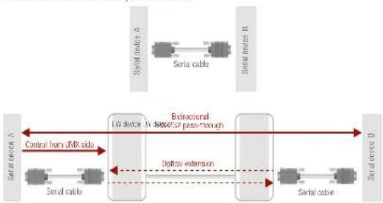
flowchart
graph LR
    A["Serial device 4"] --> B["Serial cable"]
    B --> C["Serial device 8"]
    C --> D["Serial device 3"]
    D --> E["Control from UKK sides"]
    E --> F["Serial cable"]
    F --> G["Serial device 2"]
    G --> H["Directional pass-through"]
    H --> I["Optical extension"]
    I --> J["Serial cable"]
    J --> K["Serial device 3"]
If cable's plug and device's receptacle do not match get a suitable cable or use a gender changer.
3
Product Overview
The following sections are about the physical structure of the device, input/output ports and connectors:
UMX-OPT-TX150R - FRONT VIEW
UMX-OPT-TX150R - REAR VIEW
▶ ELECTRICAL CONNECTORS
▶ PORT DIAGRAM
3.1. UMX-OPT-TX150R - Front View

text_image
DVH-IN VGA IN AUDIO 1 AUDIO 2 HDMI IN S/PDF IN VIDEO INPUT STATUS HDCP AutoSelect AVIO AVIO AVIO AVIO AVIO AVIO AVIO AVIO AVIO AVIO AVIO AVIO AVIO AVIO AVIO AVIO AVIO AVIO AVIO AVIO AVIO AVIO AVIO AVIO AVIO AVIO AVIO AVIO AVIO AVIO AVIO AVIO AVIO AVIODVI-I IN DVI-I connector for connecting the video source to the transmitter via DVI cable (DVI-DVI or DVI-HDMI) or VGA cable (with VGA-to-DVI adapter). For more information see the DVI-I Input section.
2 VGA IN D-sub connector for analog video signal. For more details see VGA Input section.
3 AUDIO 1 -2 IN 3.5 mm jack connector for unbalanced analog stereo audio input signal with right and left channel. For more information see Analog Audio Input section.
4 HDMI IN HDMI connector for DVI video or HDMI video and audio. For more details see the HDMI Input section.
5 S/PDIF Input RCA jack connector with S/PDIF digital audio signal. For more information see S/PDIF Input section.
6 Status LEDs The LEDs give feedback about state of the unit and the video and audio signals. For more information about names and meanings of the Status LEDs see Front Panel LEDs section.
7 VIDEO SELECT Button for switching between video inputs (DVI-D / DVI-A / VGA / HDMI / Autoselect) is available with the VIDEO select button. For more information see in Video Input Selection section.
8 AUDIO SELECT Button for switching between audio inputs (DVI-D / Audio 1 / Audio 2 / HDMI / S/PDIF) is available with the AUDIO select button. For more information see in Audio Input Selection section.
3.2. UMX-OPT-TX150R - Rear View

text_image
1 2 3 4 5 SC MI OUT RS-232 1.0000 1.0000 BAUD RATE USB LEARN EDID MEMORY 7 RB-232 RVB RVD POW DVI-D DVI-A VGA HDMI RESET 5V 1.5A DC PIN: 205mmSC Fiber Connect a 50/125 multimode fiber optical cable (OM4 is recommended) between the SC MM OUT of the transmitter unit and the SC MM IN of the receiver unit. (e.g. HDMI-3D-OPT-RX100RA or a Lightware Hybrid Matrix equipped with fiber optical input cards). For more information see Fiber Optical Output section.
2 RS-232 Port 9-pole D-sub female connector for standard RS-232 port. Connect a serial cable between the transmitter unit and the serial device. RS-232 pass-through, third party control and Advanced EDID management are available via the RS-232 interface. For more information read RS-232 Port and Connection of Serial Devices chapters.
3 BAUD RATE The rotary switch selects one of 5 speeds of the serial communication (#1 .. #4) Rotary Switch or the Software Control mode (#0). The #8 and #9 states are used for special functions.
4 USB Port USB mini B-type connector for standard USB port. Connect a USB A - Mini USB B cable between the transmitter unit and the computer. Advanced EDID Management, control and firmware upgrades are available via the USB interface. For more information see USB Connector section.
5 LEARN Button Stores the EDID of the display device attached to receiver device's video output in the selected memory address between #6 .. #9 on the selected input port. To learn the EDID, select the desired input and an appropriate address with the rotary switches and press and hold the Learn button for two seconds. For more details about Lean button see EDID Learning section.
6 Status LEDs The LEDs give feedback about state of the unit and the video and audio signals. For more information about names and meanings of the Status LEDs see Front Panel LEDs.
7 EDID MEMORY The rotary switch selects one of 10 addresses on every input port. EDID memories Rotary Switch #1.#5 contain factory presets and #6.#9 are user programmable. Address #0 enable dynamic EDID emulation which copies EDID from receiver device's video output. For more information see EDID Memory Structure section.
8 RESET Button Hardware reset button. It resets the whole device, however saved settings and EDIDs will be preserved. This is the same as disconnecting from power source, and reconnect again.
9 DC 5V In Connect the output of the supplied 5V DC power adaptor
INFO: Use a flat head screwdriver to the rotary switches that fits into the actuator. Avoid the use of keys, coins, knives and other sharp objects because they might cause permanent damage to the rotary switches.


- Product Overview UMX-OPT-TX150R - User's Manual 14
3.3. Electrical Connectors
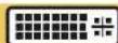
3.3.1. DVI-I Input
The transmitter unit provides standard
29-pole DVI-I connectors for DVI-D
(digital) or DVI-A (analog) inputs.
This way, users can plug in any DVI
connector, but keep in mind that the transmitter unit accepts single
link DVI, HDMI or analog (such as VGA or RGBHV) signals on the DVI
input.
INFO: Always use high quality DVI cable for connecting DVI devices.
3.3.2. VGA Input
The switcher provides a standard 15-pole D-SUB
female connector for connecting VGA devices.
Always use high-quality VGA cable for connect
the source; using a VGA cable where all the pins
are wired (including the DDC channel's wires) is highly recommended.
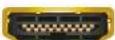
3.3.3. HDMI Input
UMX-OPT-TX150R provides standard 19 pole
HDMI connectors for input. Always use high
quality HDMI cable for connecting sources


3.3.4. Fiber Optical Output
The transmitter has multimode SC fiber optical input
connector.
INFO: Fiber optic cables can be easily damaged if they are
improperly handled or installed. Handle the optical cables with care to avoid damage.
WARNING! Avoid exposure to beam! Direct intrabeam viewing
normally hazardous.
3.3.5. Analog Audio Input
Unbalanced analog audio 1 and audio 2 can be connected to the device with TRS (Tip, Ring, and Sleeve) connectors. They are also known as (3,5 mm or approx. 1/8") audio jack, phone jack, phone plug, and mini-jack plug.
TRS connector pin assignment
| Pin nr. Signal | |
| 1 Tip Right channel | |
| 2 Ring Left channel | |
| 3 Sleeve Ground | |

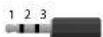
3.3.6. S/PDIF Input
UMX-OPT-TX150R has standard RCA receptacles for digital coaxial audio input.

ATTENTION! Plugs and sockets on consumer equipment are conventionally color-coded by CEA/CEDIA- 863-B (ANSI) to aid correct connections. According to the standard Lightware uses orange colored RCA connectors for S/PDIF signals.
3.3.7. RS-232 Port
UMX-OPT-TX150R has RS-232 pass-through function or can be remote controlled through industry standard 9 pole D-SUB female

D-sub connector pin assignment for standard RS-232
| Pin nr. | RS-232 |
| 1 | NC - non connected |
| 2 | TX data transmit (output) |
| 3 | RX data receive (input) |
| 4 | DTR (Internally connected to Pin 6) |
| 5 | GND signal ground (shield) |
| 6 | DSR (Internally connected to Pin 4) |
| 7 | RTS (Internally connected to Pin 8) |
| 8 | CTS (Internally connected to Pin 7) |
| 9 | NC - non connected |
3.3.8. USB Connector
UMX-OPT-TX150R has standard Mini USB Type B receptacle.

3.3.9. DC 5V Connection
Do not forget to turn the plug clockwise direction after connecting the power adaptor.
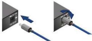
natural_image
Two diagrams showing a device with an internal component and connected cable, no text or symbols present.WARNING! Always use the supplied 5V power adaptor. Warranty is void if damage occurs due to use of a different power source.
3.4. Port Diagram
The following figure describes the port diagram of the UMX-OPT-TX150R.
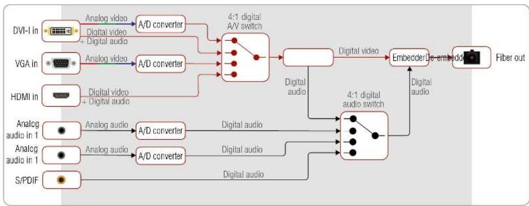
flowchart
graph LR
    DVI-I_in -->|Analog video + Digital audio| A_D["4:1 digital A/V switch"]
    VGA_in -->|Analog video + Digital audio| A_D
    HDMI_in -->|Digital video + Digital audio| A_D
    AnalogAudio1["Analog audio in 1"] -->|Analog audio| A_D0["A/D converter"]
    AnalogAudio2["Analog audio in 1"] -->|Analog audio| A_D2["A/D converter"]
    S/PDIF["S/PDIF"] -->|Analog audio| A_D2
    A_D0 --> DigitalAudio["Digital audio"]
    A_D2 --> DigitalAudio2["Digital audio"]
    DigitalAudio --> DigitalAudio3["4:1 digital audio switch"]
    DigitalAudio2 --> DigitalAudio3
    DigitalAudio3 --> EmbodeDe["Embeder De-embedd"]
    EmbodeDe --> FiberOut["Fiber out"]
    DigitalAudio3 --> DigitalAudio2
    DigitalAudio2 --> DigitalAudio3

Operation of UMX-OPT-TX150R
This chapter is about the powering and operating of the device describing the functions which are available by the front/rear controls:
▶ BOOT UP OF UMX-OPT-TX150R
FRONT PANEL LEDS
▶ REAR PANEL LEDs
▶ INPUT SELECTION
▶ VIDEO AUTOSELECT MODE
▶ AUDIO AUTOSELECT MODE
▶ EDID MANAGEMENT
HDCP MANAGEMENT
RELOAD FACTORY DEFAULTS
▶ SERVICE MENU
▶ REMOTE OPERATION
4.1. Boot up of UMX-OPT-TX150R
WARNING! When building an electronic system, make sure that all of the devices are powered down before connecting them. Powered on devices may have dangerous voltage levels that can damage sensitive electronic circuits.
After all the other connections in the system are complete, connect the output of the 5V Power Adaptor to the UMX-OPT-TX150R.
The special locking DC plug provides safe connection. Plug the connector into the 5V 1A DC IN receptacle and twist 90° clockwise to lock it. Plug the adaptor into the electric outlet. The unit is immediately powered ON.
4.1.1. Firmware Indication
After being powered on, the UMX-OPT-TX150R lights up all LEDs from top to bottom, then displays its firmware version using the three upper LEDs of the front panel VIDEO LED bar. The top LED (DVI-D) means the first number of the firmware version, actually this is the main version. From the top the second (DVI-A) and the third (VGA) LEDs mean the second and the third number of the firmware version, actually these are the subversions.
Example of the firmware version of 1.0.1.
The following Example shows this process for a firmware version of 1.0.1.
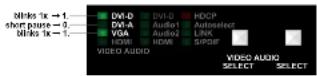
The top LED (DVI-D) blinks once → Short pause → The second LED (DVI-A) does not blink, this means the number 0 → Short pause → The third LED (VGA) blinks once → Short pause → The normal function of the LED is in effect.
After indicating the firmware version, UMX-OPT-TX150R checks the video output: reads the EDID if there is a Hot Plug signal and authenticates devices in case of HDCP encryption. This procedure takes approximately 5 seconds.
UMX-OPT-TX150R stores the video and audio crosspoint state in a non-volatile memory and after booting it starts with it.
After the UMX-OPT-TX150R is initialized, the attached source(s), receiver pair and monitor(s) can be powered on.
INFO: If none of the LEDs light up upon power-up, the unit is most likely damaged and further use is not advised. Please contact support@lightware.eu.
4.2. Front Panel LEDs
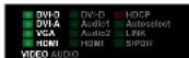
VIDEO Status LEDs (DVI-D, DVI-A, VGA, HDMI) is
- ON when the video input port is selected and there is a valid video signal on it.
- BLINKING when the video input
port is selected and there is no valid video signal on it.
OFF when the video input port is NOT selected. Another port is active or there was a disconnect command.
AUDIO Status LED (DVI-D, Audio 1, Audio 2, HDMI, S/PDIF) is
• ON when the audio input port is selected.
- OFF when the audio input port is NOT selected. Another port is active or there was a disconnect command.
INFO: When all the front panel LEDs are blinking, they refers to the undefined baud rate settings (baud rotary switch is set from #5 to #9).
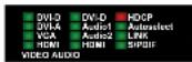
HDCP LED is
• ON when the HDCP setting of the output video signal is Always.
OFF when the HDCP setting of the

Autoselect LED is
- ON when the autoselect mode is selected and a valid video signal is found.
BLINKING when the autoselect mode is selected and video signal searching is in progress.
OFF when autoselect mode is not selected and video input port can be chosen manually.


- Operation of UMX-OPT-TX150R UMX-OPT-TX150R - User's Manual 17
LINK LED is
- ON when the TX and the RX (or OPT-IB) are connected to each other via the optical cable and they can communicate.
- OFF when the TX and RX (or OPT-IB) are not connected or they CANNOT communicate.

4.3. Rear Panel LEDs
RS-232 LED is
- ON when the RS-232 is in Control mode. - OFF when the RS-232 is in Pass mode.
KVM LED is
always OFF in this firmware version.
EDID LED is
- ON when there is a valid EDID on the currently active input port.
- BLINKING FAST continuously when there is an invalid EDID on the currently active input port.
- BLINKS FAST THREE TIMES when EDID learning was unsuccessful.
- BLINKS SLOW THREE TIMES when EDID learning was successful.
PWR LED is
- ON when the transmitter unit is powered with 5V DC and ready to use.
- BLINKING when the transmitter unit is powered but an error occurred.
- OFF when the transmitter unit is NOT powered or out of order.


4.4. Input Selection
Video and Audio input can be chosen by:
- Video and Audio Select button on the front panel (see UMX-OPT-TX150R - Front View section).
- Autoselect mode: (Video Autoselect Mode and Audio Autoselect Mode.)
- Software Control – Lightware Device Controller software
- Protocol command (Switch One Input to One Output or View All Connections on the Output)
Video Input Selection
The order of the video selection is shown below. After the Video Select button is pushed, the next video input will be chosen. The corresponding LED lights up.

4.4.2. Audio Input Selection
The order of the audio selection depends on the selected video input. The available audio inputs are shown below. After the Audio Select button is pushed, the next input will be chosen. The corresponding LED lights up.
In case of analog video inputs (DVI-A and VGA) any audio input can be selected. After the Audio Select button was pushed, the next audio input will be chosen. The corresponding LED lights up.

In case of the digital video inputs (DVI-D and HDMI) the embedded audio input of the selected video input, the analog audio 1, analog audio 2 inputs and the S/PDIF audio can be selected.
It means that analog audio input 1, analog audio input 2, HDMI embedded and S/PDIF audio inputs can be used for HDMI video input

The DVI-D embedded audio, analog audio input 1, analog audio input 2 and S/PDIF audio inputs can be used for DVI-D video input.

4.5. Video Autoselect Mode
The Autoselect function means UMX-OPT-TX150R can recognize the incoming valid video on all the input ports and can choose one automatically, without user intervention. Autoselect searching starts after an event. It can be the stepping into Autoselect mode, plugging or unplugging a video or audio cable or appearing or disappearing a valid video signal.
Video Input in Autoselect Mode
ATTENTION! DVI-D, VGA and HDMI video inputs are available for video autoselect. DVI-A input can be chosen manually only.
The video Autoselect mode can work in three ways:
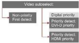
4.5.1. Non-Priority (First Detect)
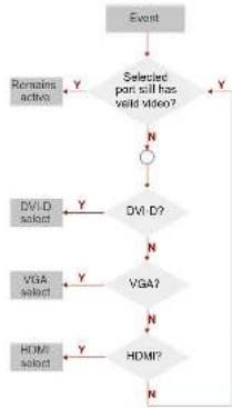
The device will select that port, where a valid video signal appears at first.
If the selected input was unplugged or the valid video signal was disappeared, the searching process starts again from the DVD input. Until there is a valid video signal on the selected port, the searching process does not start again.
flowchart
graph TD
    A["Event"] --> B{Selected port still has valid video?}
    B -->|Y| C["Remains active"]
    B -->|N| D["DVI-D?"]
    D -->|Y| E["DVI-D select"]
    D -->|N| F["VGA?"]
    F -->|Y| E
    F -->|N| G["HDMI?"]
    G -->|Y| E
    G -->|N| H["HDMI select"]


- Operation of UMX-OPT-TX150R UMX-OPT-TX150R - User's Manual 18
4.5.2. HDMI Digital Priority
The device will select the HDMI port, if there is a valid video sign in it.
If one of the input ports (e.g. VGA) was selected and there is a valid video signal on it and a valid video signal was appeared on the HDMI input port - by connecting or powering on a video source, the searching process starts again with checking the video signal on the HDMI input.
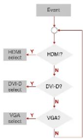
flowchart
graph TD
    A["Event"] --> B{HDM?}
    B -->|Y| C["HDMI select"]
    B -->|N| D["DVI-D?"]
    C --> E["VGA?"]
    D --> F["VGA?"]
    E --> G["VGA?"]
    F --> G
4.5.3. DVI-D Digital Priority
The device will select the DVI-D port, if there is a valid video sign in it.
If one of the input ports (e.g. VGA) was selected and a valid video signal was appeared on the DVI-D input port - by connecting or powering on a video source, the searching process starts again with checking the video signal on the DVI-D input.
User can toggle between the three video Autoselect priority modes with the Lightware Device Controller software (see Autoselect Settings chapter), or Service Menu.
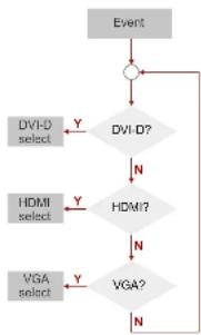
flowchart
graph TD
    A["Event"] --> B{DVI-D?}
    B -->|Y| C["DVI-D select"]
    B -->|N| D["HDMI select"]
    C --> E{HDMI?}
    D --> E
    E -->|Y| F["VGA?"]
    E -->|N| G["VGA?"]
    F -->|Y| H["VGA?"]
    F -->|N| I["End"]
4.6. Audio Autoselect Mode
The Autoselect function means UMX-OPT-TX150R can recognize the incoming valid video and audio signals on all the input ports and can choose one automatically, without user intervention. Autoselect searching starts after an event. It can be the stepping into Autoselect mode, plugging or unplugging a video or audio cable or appearing or disappearing a valid video or audio signal.
Audio inputs, which are available for audio Autoselect mode:
• DVI-D or HDMI embedded (either of them, depends on the result
of the video autoselect)
S/PDIF and
- Analog audio 2
Audio input, which can be chosen manually only:
- Analog audio 1
The audio Autoselect mode can work in ten ways:
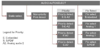
flowchart
graph TD
    A["Static select"] --> B["Non-priority First detect"]
    B --> C["Priority Detect E-S-A2"]
    B --> D["Priority Detect S-E-A2"]
    B --> E["Priority Detect E-A2"]
    B --> F["Priority Detect S-A2"]
    C --> G["Fix Select Fix select Embedded"]
    D --> H["Fix Select Analog 1"]
    E --> I["Fix Select Analog 2"]
    F --> J["Fix Select SP/DF"]
    style A fill:#f9f,stroke:#333
    style B fill:#ccf,stroke:#333
    style C fill:#cfc,stroke:#333
    style D fill:#cfc,stroke:#333
    style E fill:#cfc,stroke:#333
    style F fill:#cfc,stroke:#333
    style G fill:#fcc,stroke:#333
    style H fill:#fcc,stroke:#333
    style I fill:#fcc,stroke:#333
    style J fill:#fcc,stroke:#333
User can toggle between the ten audio Autoselect priority modes with the Lightware Device Controller software (see details in Autoselect Settings chapter), or with the Service Menu.
4.6.1. Static Select
In this mode all audio inputs are assigned to the video inputs statically:
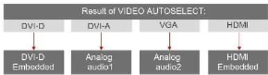
flowchart
graph TD
    A["DVI-D"] --> B["DVI-D Embedded"]
    C["DVI-A"] --> D["Analog audio1"]
    E["VGA"] --> F["Analog audio2"]
    G["HDMI"] --> H["HDMI Embedded"]
4.6.2. Non-Priority (First Detect)
After the video Autoselect the device checks the embedded audio input.
DVI-D embedded audio input to the DVI-D video input or HDMI embedded audio input to the HDMI video input.
A valid embedded audio signal it will be selected if it exists.
If there is no valid embedded audio signal the device checks the audio inputs. First, it checks S/PDIF, then Analog audio 2 port.
In case of an event (any audio is plugged or unplugged) the selected port remains the active input port if there is a valid audio signal on it.
If the audio signal disappears on the selected port the searching process starts again.
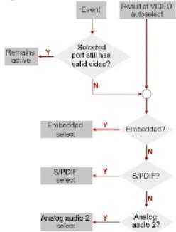
flowchart
graph TD
    A["Event"] --> B["Selected port still has valid video?"]
    B --> C{N}
    C -->|Yes| D["Result of VIDEO autoSelect"]
    D --> E["Embedded?"]
    E --> F{SVPDF?}
    F -->|Yes| G["SVPDF select"]
    F -->|No| H["Analog audio 2?"]
    G --> I["Analog audio 2 select"]
    H --> I
    style A fill:#f9f,stroke:#333
    style D fill:#ccf,stroke:#333
    style E fill:#cfc,stroke:#333
    style F fill:#fcc,stroke:#333
    style G fill:#cff,stroke:#333
    style H fill:#ffc,stroke:#333
4.6.3. Priority Detect
In priority detect mode, the result of the video autoselect declares the embedded audio input.
If the selected video port is the DVI-D, the embedded audio input will be DVI-D also. If the selected video port is the HDMI, the embedded audio input will be HDMI.
Embedded, S/PDIF, Analog Audio 2
After the video Autoselect the device checks the audio inputs in a pre-defined order:
First, it checks embedded audio, then S/PDIF and final the Analog audio 2 port.
• If there is a valid audio signal, it will be selected.
- If the device can not find any audio signal, audio 2 input will be selected.
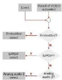
flowchart
graph TD
    A["Event"] --> B(( ))
    B --> C["Result of VIDEO audio select"]
    C --> D["Embeddsc?"]
    D --> E["N"]
    E --> F["SPDF?"]
    F --> G["N"]
    G --> H["Analog audio 2?"]
    H --> I["Y"]
    I --> J["Embeddsc select"]
    J --> K["Y"]
    K --> L["SPDF select"]
    L --> M["Y"]
    M --> N["Analog audio 2?"]
INFO: Any audio event occurs a new searching from the embedded input port.
INFO: The selected audio input will be active until the new result of video Autoselect or a new audio event.
S/PDIF, Embedded, Analog Audio 2
After the video Autoselect the device checks the audio inputs in a pre-defined order:
First, it checks S/PDIF, then embedded audio and final the analog audio 2 port.
- If there is a valid embedded audio signal it will be selected.
- If there is no valid embedded audio signal on the embedded input port the device selects the analog audio 2 input, even if there is no audio signal on this input.
INFO: Any audio event occurs a new searching from the S/PDIF input port.
INFO: The selected audio input will be active until a new result of video Autoselect, an audio event.
Embedded, Analog Audio 2
After the video Autoselect the device checks the embedded audio input.
- If there is a valid embedded audio signal it will be selected.
- If there is no valid embedded audio signal the device selects the analog audio 2 input, even if there is no audio signal on this input.
INFO: Any audio event occurs a new searching from the embedded input port.
INFO: The selected audio input will be active until a new result of video Autoselect, an audio event or the device exits from the Autoselect mode.
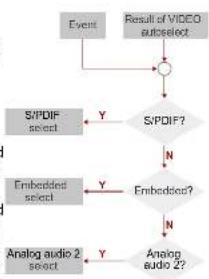
flowchart
graph TD
    A["Event"] --> B{Result of VIDEO autoselect}
    B -->|Y| C["S/PDIF select"]
    B -->|N| D["Embedded select"]
    C --> E["S/PDIF?"]
    D --> F["Embeddings?"]
    E --> G["Analog audio 2 select"]
    F --> H["Analog audio 2?"]
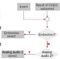
flowchart
graph TD
    A["Event"] --> B(( )) --> C["Result of VIDEO subspect"]
    B --> D["Embedded?"]
    D --> E["Embedded select"]
    E --> F["Y"]
    D --> G["N"]
    F --> H["Analog audio 2 select"]
    G --> I["Analog audio 2?"]
flowchart
graph TD
    A["Event"] --> B(( )) --> C["Result of VIDEO subspect"]
    B --> D["Embedded?"]
    D --> E["Embedded select"]
    E --> F["Y"]
    D --> G["N"]
    F --> H["Analog audio 2 select"]
    G --> I["Analog audio 2?"]
S/PDIF, Analog Audio 2
After the video Autoselect the device checks the S/PDIF audio input.
- If there is a valid S/PDIF audio signal on the S/PDIF audio input it will be selected.
- If there is no valid audio signal on the S/PDIF audio input port the device selects
the analog audio 2 input, even if there is no audio signal on this input.
INFO: Any audio event occurs a new searching from the S/PDIF input port.
INFO: The selected audio input will be active until a new result of video Autoselect, an audio event.
4.6.4. Fix Selection
Fix selection mode is independent of the result of video autoselect or the active audio signal.
All audio inputs can be chosen: Embedded, Analog Audio 1, Analog Audio 2, S/PDIF.
The selected audio input is active until another Audiopriority setting or the device exits from the Autoselect mode.
4.7. EDID Management
About EDID Memory
EDID memory is non-volatile and consists of four blocks, each for different purpose. These blocks are:
• Factory preset EDIDs
- User saved EDIDs
- Dynamic EDID (EDID of last connected sink on the DDC output port)
- Emulated EDIDs (EDID currently emulated on a specific input port)
This manual refers to the EDIDs in two ways. Using, selecting EDIDs with Lightware Device Controller (LDC) software or with Rotary switches.
4.7.1. EDID Memory Structure
EDIDs Are Referred with Lightware Device Controller
In the first case EDID is mentioned with the Lightware Device Controller software or the protocol commands.
Factory Preset EDIDs (F01 .. F20):
F01..F05.....DVI-D Factory Preset EDIDs
F06..F10 DVI-A Factory Preset EDIDs
F11..F15...... VGA Factory Preset EDIDs
F16..F20......HDMI Factory Preset EDIDs
INFO: The factory EDIDs (Fxx) are factory preprogrammed and cannot be modified. These are the most commonly used resolutions.
User programmable memories (U01 .. U16):
U01..U04....User programmable DVI-D memories
U05..U08....User programmable DVI-A memories
U09..U12User programmable VGA memories
U13..U16....User programmable HDMI memories
Last attached monitor's EDID: (D01):
D01 Last attached monitor's EDID on the output
INFO: The attached monitor's EDID is the Lightware Universal EDID by factory default.
Emulated EDIDs (E01 .. E04):
E01.....Emulated EDIDs on the DVI-D input
E02.....Emulated EDIDs on the DVI-A input
E03 ...... Emulated EDIDs on the VGA input
E04 ...... Emulated EDIDs on the HDMI input
INFO: UMX-OPT-TX150R can handle both 128 Byte EDID and 256 Byte extended EDID structures.
EDIDs Are Referred with Rotary Switches
In the second case EDID is mentioned with the rear panel rotary switches. EDIDs are numbered from 0 on each rotary, and they can be referred with hash symbol, and the number of the desired EDID. This way #6 on the DVD-D rotary refers to the first user preset EDID (U01), and #0 refers to the display device's EDID (called Dynamic or Last attached monitor's EDID) on the output (on the DDC output).
ATTENTION! Emulated EDIDs can be switched with the rotary
switches only.
The Assigning Table
To help understand the EDID memory structure. See the table of Factory EDID List. It shows all the EDIDs, their short descriptions and their references.
All EDIDs (including factory presets; user programmable memories and EDID at SC MM output) can be switched and emulated at any of the inputs.
Example State of the Rotary Switches
The rotary switches select the EDIDs highlighted gray in the tables below.
The rotary switches have the following state:

DVI-D Rotary is in #2 state, it means Factory EDID (DVI)
1024x768@60 is the selected EDID on the DVI-D input port.
| DVI-D EDID Rotary | ||
| #0 Copy from SC MM OUT (Dynamic EDID) D01 | ||
| #1 Factory EDID Universal HDMI (default) F01 | ||
| #2 Factory EDID (DVI) 1024x788@60 F02 | ||
| #3 Factory EDID (HDMI) 1280x720p@60 F03 | ||
| #4 Factory EDID (HDMI) 1920x1080p@60 | F04 | |
| #5 Factory EDID (DVI) 1920x1200@60 | F05 | |
| #6 User EDID (def.: Univ. HDMI EDID) | U01 | |
| #7 User EDID (def.: Univ. HDMI EDID) | U02 | |
| #8 User EDID (def.: Univ. HDMI EDID) | U03 | |
| #9 User EDID (def.: Univ. HDMI EDID) | U04 | |

DVI-A Rotary is in #5 state, it means Factory EDID (Analog) 1920x1200@60 is the selected EDID on the DVI-A input port.
| DVI-A EDID Rotary | ||
| #0 | Copy from SC MM OUT (Dynamic EDID) | D01 |
| #1 | Factory EDID Universal Analog (default) | F06 |
| #2 | Factory EDID (Analog) 1024x768@60 | F07 |
| #3 | Factory EDID (Analog) 1280x720@60 | F08 |
| #4 | Factory EDID (Analog) 1920x1080@60 | F09 |
| #5 | Factory EDID (Analog) 1920x1200@60 | F10 |
| #6 | User EDID (def.: Univ. Analog EDID) | U05 |
| #7 | User EDID (def.: Univ. Analog EDID) | U06 |
| #8 | User EDID (def.: Univ. Analog EDID) | U07 |
| #9 | User EDID (def.: Univ. Analog EDID) | U08 |

VGA Rotary is in #0 state, it means Dynamic EDID is the selected EDID on the VGA input port. (The EDID will be copied from SC MM OUT).
| VGA EDID Rotary | ||
| #0 | Copy from SC MM OUT (Dynamic EDID) | D01 |
| #1 | Factory EDID Universal Analog (default) | F11 |
| #2 | Factory EDID (Analog) 1024x768@60 | F12 |
| #3 | Factory EDID (Analog) 1280x720@60 | F13 |
| #4 | Factory EDID (Analog) 1920x1080@60 | F14 |
| #5 | Factory EDID (Analog) 1920x1200@60 | F15 |
| #6 | User EDID (def.: Univ. Analog EDID) | U09 |
| #7 | User EDID (def.: Univ. Analog EDID) | U10 |
| #8 | User EDID (def.: Univ. Analog EDID) | U11 |
| #9 | User EDID (def.: Univ. Analog EDID) | U12 |

HDMI Rotary is in #8 state, it means the 3rd User EDID is the selected EDID on the HDMI input port.
| HDMI EDID Rotary | ||
| #0 Copy from SC MM OUT (Dynamic EDID) D01 | ||
| #1 Factory EDID Universal HDMI (default) F16 | ||
| #2 Factory EDID (DVI) F17 | ||
| #3 Factory EDID (HDMI) F18 | ||
| #4 Factory EDID (HDMI) F19 | ||
| #5 Factory EDID (DVI) F20 | ||
| #6 User EDID (def.: Univ. HDMI EDID) U13 | ||
| #7 User EDID (def.: Univ. HDMI EDID) U14 | ||
| #8 User EDID (def.: Univ. HDMI EDID) | U15 | |
| #9 User EDID (def.: Univ. HDMI EDID) | U16 | |
Switching the EDID with a Rotary Switch
Use a screwdriver to change the memory address on the rear side of the UMX-OPT-TX150R. After either one of the rotary switches has been rotated, the unit waits approximately 2 seconds before the selected EDID becomes active.
INFO: After every EDID change, UMX-OPT-TX150R toggles the HOT PLUG signal for approx. 1 second. Some graphic cards or DVD players do not sense the HOT PLUG signal, and even if EDID has been changed, the set resolution is not affected. In this case the source device must be restarted, or powered OFF and ON again.
ATTENTION! Switching EDID for any inputs is available only with rotary switches. (Switching with Lightware Device Controller Software or protocol command is not available.)
4.7.2. Deleting the EDID
Deleting EDID is available only with Lightware Device Controller Software. Only user EDIDs can be deleted. Deleting means the factory EDID (Universal HDMI or Analog EDID) will be loaded into the desired user EDID memory.
4.7.3. EDID Types
Most of the factory preset EDIDs include only one resolution. This is to force the connected source to give a signal with the needed resolution. However there are Universal EDIDs as well which allow many resolutions.
The factory EDIDs are divided into groups regarding their type. Some EDIDs are supporting DVI only, some support HDMI, and some are for analog VGA signals.
• Analog EDIDs can be used for VGA (RGBHV) input port.
• DVI EDIDs does not support embedded audio.
- HDMI EDIDs support embedded audio. These EDIDs - include Universal HDMI EDID - indicate that any audio Format is accepted (PCM, Dolby, DTS, etc.).
INFO: Analog and HDMI user EDIDs are the Universal Analog and HDMI EDIDs in factory defaults.
Factory Preset EDID List
Lightware factory pre-loaded EDIDs are specially provided to force graphic cards to output only the exact pixel resolution and refresh rate. HDMI and VGA universal EDIDs (#1 on both rotary switches) allow multiple resolutions including all common VESA defined resolutions. In addition, HDMI universal EDID also features audio support. The use of universal EDID is recommended for fast and easy system setup.
| Mem. | Resolution | Type | Audio support | Deep color support | |||
| PCM | Other | 24 bit | 30 bit | 36 bit | |||
| F01 | Universal_HDMI_DC | HDMI | √ | √ | √ | - | √ |
| F02 | 1024 x 768 @ 60.0 Hz | DVI | - | - | - | - | - |
| F03 | 1280 x 720 @ 60.0 Hz | HDMI | √ | - | √ | - | - |
| F04 | 1920 x 1080 @ 60.0 Hz | HDMI | √ | - | √ | - | - |
| F05 | 1920 x 1200 @ 59.55 Hz | DVI | - | - | - | - | - |
| F06 | Universal_Analog | Analog | - | - | - | - | - |
| F07 | 1024 x 768 @ 60.0 Hz | Analog | - | - | - | - | - |
| F08 | 1280 x 720 @ 60.0 Hz | Analog | - | - | - | - | - |
| F09 | 1920 x 1080 @ 60.0 Hz | Analog | - | - | - | - | - |
| F10 | 1920 x 1200 @ 59.55 Hz | Analog | - | - | - | - | - |
| F11 | Universal_Analog | Analog | - | - | - | - | - |
| F12 | 1024 x 768 @ 60.0 Hz | Analog | - | - | - | - | - |
| F13 | 1280 x 720 @ 60.0 Hz | Analog | - | - | - | - | - |
| F14 | 1920 x 1080 @ 60.0 Hz | Analog | - | - | - | - | - |
| F15 | 1920 x 1200 @ 59.55 Hz | Analog | - | - | - | - | - |
| F16 | Universal_HDMI_DC | HDMI | √ | √ | √ | - | √ |
| F17 | 1024 x 768 @ 60.0 Hz | DVI | - | - | - | - | - |
| F18 | 1280 x 720 @ 60.0 Hz | HDMI | √ | - | √ | - | - |
| F19 | 1920 x 1080 @ 60.0 Hz | HDMI | √ | - | √ | - | - |
| F20 | 1920 x 1200 @ 59.55 Hz | DVI | - | - | - | - | - |
INFO: The F01..F20 EDIDs are factory preprogrammed and cannot be modified. These are the most commonly used resolutions.
4.7.4. EDID Learning
Learning the EDID function enables to store the EDID of the display which connected to the receiver in UMX-OPT-TX150R's memory.
The factory preset EDIDs cannot be changed by the user. Only addresses #6 .. #9 (on any rotary switches) are user programmable.
ATTENTION! EDID learning is only available from the active input to a user memory location which was selected by a rotary switch. EDID learning is not allowed in AUTOSELECT mode.
INFO: Before a digital EDID will be selected to an analog output port UMX-OPT-TX150R removes the digital descriptor from the EDID and selects it.
Step 1. Connect the sink device to the unit's output (for Example the receiver unit's HDMI OUT)
Step 2. Use a screwdriver to select an empty memory address. (for Example on a HDMI rotary set the #6)
Step 3. Push the Learn button on the front side of the device and hold it down for approximately 3 seconds.
Step 4. If the EDID storing was successful on the active port, the EDID LED blinks 3 times in 3 seconds slowly then they return to their original function. EDIDs are stored in a multiple programmable non-volatile memory.
If the storing was unsuccessful on the active port, the EDID LED blinks 3 times in 1 second quickly then they return to their original function.
INFO: The last attached monitor's EDIDs are stored automatically, until a new monitor is attached to the output (or receiver's output). In case of powering the unit off, the last attached monitor's EDID remains in non-volatile memory.
4.7.5. EDID Switching
Use a screwdriver to change the memory address on the rear side of the UMX-OPT-TX150R.
After any of the rotary switches has been rotated, the unit waits approximately 2 seconds before the selected EDID becomes active.
The address #0 (on any rotary switches) has a special function. If a receiver is connected to the output, then its EDID is copied to the input connector. If no receiver is connected to the output then the EDID transmitted to the input connector is the EDID of the last connected monitor.
INFO: After every EDID change, UMX-OPT-TX150R toggles the HOT PLUG signal for approx. 1 second. Some graphic cards or DVD players do not sense the HOT PLUG signal, and even if EDID has been changed, the set resolution is not affected. In this case the source device must be restarted, or powered OFF and ON again.
ATTENTION! Switching EDID for any inputs is available only with rotary switches. (Switching with protocol command is not available, for more details about switching with Lightware Device Controller Software see Changing Emulated EDID section).
The UMX-OPT-TX150R can work as a HDCP compliant device, or act as a non-HDCP compliant sink. The HDCP capability can be disabled or enabled on the digital video input ports (DVI-D, HDMI). This function helps to apply encryption only when it is mandatory.
Some video sources send encrypted signal when they are connected to a HDCP capable device even if the content is not protected. This way even the unprotected content cannot be displayed on non-HDCP displays if the signal travels through a HDCP compliant matrix or repeater.
However HDCP encryption is not required all the time (e.g. computer desktop image) some video cards still encrypt if they detect that the sink is HDCP capable.
Avoiding Unnecessary HDCP Encryption
If HDCP is disabled on any digital video input port, the connected source will detect that the sink is not HDCP capable, and turn off authentication. The source will not be able to communicate with any of the devices (displays, repeaters, etc.) that are connected to the receiver's output, therefore it could not see if they are HDCP capable or not.
This forces the source to send unprotected signal only. If HDCP capability is disabled on an input port, the connected source cannot send protected content to any display. If HDCP function is enabled on an input port and the source sends encrypted signal, the non-HDCP compliant devices cannot display the video.
INFO: In HDCP disable mode, protected content (i.e. Blu-ray disc) will not be displayed, thus maintaining the rules set by the HDCP standard.
To toggle the HDCP function on the desired input port, use Lightware Device Controller software (HDCP Enable) or turn the desired digital input's rotary switch to address #1, and press and hold the Learn button for approximately 5 seconds.


= HDCP enable / disable on DVI-D input

+ = HDCP enable / disable on HDMI input
The status change appears on the front panel's LED tower. When the status changed the EDID LED blinks three times quickly.
HDCP Key Counter
HDCP key counter is a tool that counts and validates the number of keys that can be accepted by a source device when connected to an HDCP repeater.
HDCP key counting is available with protocol command. For more information, see Count HDCP Keys section.
4.9. Reload Factory Defaults
Factory default settings can be reloaded with the procedure below:

Turn all of the rotary switches to address #0, and press and hold the Learn button for approximately 10 seconds.
After restoring default values press the Reset button to reboot the device. This operation affects the crosspoint table and configuration, I/O settings and stored User and Dynamic EDIDs and the RS-232 mode
This process can be induced by protocol command as well. For more information see Reload Factory Defaults section.
WARNING! User and Dynamic EDIDs will be cleared (refilled with Lightware Universal EDID) after reloading the factory defaults.
WARNING! Reloading factory defaults by rotary switches plus learn button AFFECTS the serial operation mode and the RS-232 baud rate options as well. The default operation mode is the PASS mode and the default baud rate is 57600 baud in the UMX-OPT-TX150R. If the previous serial settings differ from the default ones, please set up the necessary values after reboot with protocol commands. (See details about the protocol commands in Set the RS-232 Operation Mode section and the Change RS-232 Baud Rate section).


- Operation of UMX-OPT-TX150R UMX-OPT-TX150R - User's Manual 23
4.10. Service Menu
The service menu allows changing some main services (without using any controller software) which are not available directly with front or rear panel operation.
The menu contains functions (what device has e.g. Video priority mode, Output mode) as a menu items and every function have some (at least two) values can be set. There is no submenu.
INFO: The normal operation is suspended if the device enter the service menu. Video, audio and RS-232
transmission is stopped during the service menu. Signal transmission will be restored after a reboot.
4.10.1. Enter the Service Menu of UMX-OPT-TX150R
Step 1. Supply the unit with 5V DC
Step 2. Press and hold the Reset button.
Step 3. While pressing and holding the Reset button press and hold the Video Select button.
Step 4. Release the Reset button.
Step 5. Release the Video Select button.
INFO: Don't need to unplug video or fiber cables to enter the service menu.
4.10.2. Service Menu Display and Navigation
The service menu uses the device's LEDs to inform the user.
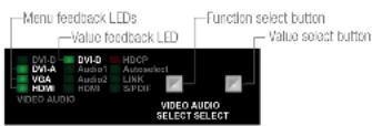
Menu Feedback LEDs
Some of the devices' LEDs (three or four LEDs in generally) show the number of the currently selected function (menu item) IN BINARY FORM. These LEDs are called menu feedback LEDs.
The menu feedback LEDs are the DVI-A, VGA and HDMI VIDEO LEDs in case of the UMX-OPT-TX150R.
The next table contains a detailed Example of a binary display.
| Binary form by LEDs | Decimal form | Menu item | |
| LED 1 | DVR-2 | 1st function Output mode | |
| LED 2 | DVR-A | ||
| LED 3 | DVR-B | ||
| LED 4 | DVR-3 | 2nd function | HDCP input mode for all inputs |
| LED 5 | DVR-A | ||
| LED 6 | DVR-B | ||
| LED 7 | DVR-3 | 3rd function | HDCP output mode |
| LED 8 | DVR-2 | ||
| LED 9 | DVR-A | ||
| LED 10 | DVR-B | ||
| LED 11 | DVR-A | ||
| LED 12 | DVR-B | ||
| LED 13 | DVR-3 | 4th function | NoSyncScreen enable for all inputs |
| LED 14 | DVR-2 | ||
| LED 15 | DVR-A | ||
| LED 16 | DVR-B | ||
| LED 17 | DVR-3 | 5th function | Video priority |
| LED 18 | DVR-2 | ||
| LED 19 | DVR-A | ||
| LED 20 | DVR-B | ||
| LED 21 | DVR-3 | 6th function | Audio priority |
| LED 22 | DVR-2 | ||
| LED 23 | DVR-A | ||
| LED 24 | DVR-B | ||
Value Feedback LED

Audio DVI-D LED shows the number of the currently selected value of the selected menu item by its blinking number. It is called value feedback LED. If the selected menu item contains six values can be set the LED can be blinks from one to six according the number of the selected value. If the
selected value is the 5th one the LED blinks 5 times. After a short break the LED starts blinking 5 times again.
The next table shows the modifiable values of all the menu items and the equivalent blinking numbers.
| Decimal form | Menu item | Number of blinks on DVI-D audio LED with the available settings | |||||
| 1x | 2x | 3x | 4x | 5x | 6x | ||
| 1st function | Output mode | Auto | DVI | HDMI 24 | n/a | n/a | n/a |
| 2nd function | HDCP input mode for all inputs | Disable | Enable | n/a | n/a | n/a | n/a |
| 3rd function | HDCP output mode | Auto | Always | n/a | n/a | n/a | n/a |
| 4th function | NoSyncScreen enable for all inputs | Disable | Enable | n/a | n/a | n/a | n/a |
| 5th function | Video priority | First detect | DVI-D priority | n/a | n/a | HDMI priority | n/a |
| 6th function | Audio priority | Static select | First detect | Priority E - S - A2 | Priority S - E - A2 | Priority E - A2 | Priority S - A2 |
| 7th function | Audio fix | Embedded | Analog 1 | Analog 2 | S/PDIF | n/a | n/a |


- Operation of UMX-OPT-TX150R UMX-OPT-TX150R - User's Manual 24
WARNING! The values (enable / disable) of the HDCP input mode and the NoSyncScreen functions (in the highlighted rows) can be set for every input port separately during the normal operation. The service mode set the value FOR ALL THE INPUT PORTS. The value feedback LED shows enable value if the NoSyncScreen or the HDCP is enabled on ANY input port.
INFO: The audio priority modes use the following abbreviations: E Embedded, S - S/PDIF, A1 - Analog 1, A2 - Analog 2 audio input port. For the detailed explanation of the Autoselect mode see Audio Autoselect Mode chapter.
Navigation in the Service Menu
The VIDEO SELECT button is the function select button and the AUDIO SELECT button is the value select button in case of the UMX-OPT-TX150R. After the entering the 1st menu item and the last saved value will be selected.
INFO: The functions and the settings in the service menu can be modified by Lightware Device Controller software or protocol commands, as well. The last saved values mean the last saving by any way, instead of the last saving by the service menu.
After every pressing of the function select button the next function will be selected. (The value feedback LED shows the corresponding last saved value.) The first menu item will be selected after the last one. After every pressing of the value select button the next value will be selected. The first value will be selected after the last one.
4.10.3. Saving in the Service Menu
The saving time is three seconds in case of the UMX-OPT-TX150R. In the service menu the device saves every value changing after three seconds automatically. If the device exits from service menu (because of a hardware reset) before 3 seconds after a value changing the last modification will be lost.
4.10.4. Exit from Service Menu
During the service menu the device is suspends its normal operation. The signal transmission and the communication (USB, RS-232 control and RS-232 pass-through) are out of work in this case. The only way to restore the normal operation is a hardware reset. It can be performed by pushing and releasing the Reset button on the rear side of the device or just plugging out then plugging in the power supply. The saved settings are stored in an external storage and the device keeps that after reboot.
4.11. Remote Operation
UMX-OPT-TX150R can be controlled through various interfaces remotely. This makes it possible to use functions that are not accessible via the front panel. Also, this helps system integrators and operators to control multiple devices in a big system through a single user interface.
4.11.1. Control Interfaces
Users can connect to the transmitter through
- USB
- Serial port (RS-232)
After establishing connection, there is no difference between connection types (except some rare cases, which are uniquely noted). The available remote connections and the relating chapters are listed below.
| User Interface | Connection type | Further Information | |
| USB port | RS-232 serial port | ||
| Lightware Device Controller software | √ | √ | Software Control – Lightware Device Controller |
| Third-party control system | - | √ | LW2 Protocol Description |
4.11.2. Multiple Simultaneous Connections
The transmitter allows simultaneous remote control over multiple interfaces. USB and Serial connections can be used at the same time.
4.11.3. RS-232 Operation Modes
Serial Port Settings
UMX-OPT-TX150R uses RS-232 communication port. The device uses standard RS-232 interface with the following default settings:
57600 Baud, 8 data bit, 1 stop bit, no parity
The serial port baud rate can be changed with the Baud Rate rotary (addresses #1 .. #4) on the rear panel (UMX-OPT-TX150R - Rear View) or remotely by protocol command in case of #0 Baud Rate rotary state (in Change RS-232 Baud Rate section).
There are two kinds of operations for the unit regarding the serial port: you can control the unit via USB and serial port or use the bidirectional
serial link through the fiber optical cable with a compatible fiber optical receiver.
Control Mode
In the first case the CPU in the transmitter can receive commands and send responses either to and from the own serial port or to and from the serial port on the receiver unit through the fiber optical cable.
Pass-Through Mode
In case of the second mode the serial connectors on the transmitter and on the receiver are linked together through the fiber optical cable
Changing the Working Mode
Step 1. Tum the Baud Rate rotary switch to address #8
Step 2. Press and hold the Learn button for approximately 3 seconds. (The addresses of EDID Memory rotary switches can be anything.)
Step 3. The current status can be seen on the rear panel LED tower. If the working mode is Pass-through the RS-232 LED is off. If the working mode is Control the RS-232 LED lights continuously.


Toggle between pass and control mode
Changing the working mode can be done by protocol command (see details Set the RS-232 Operation Mode section).
INFO: UMX-OPT-TX150R stores the RS-232 working mode and starts the saved one after reboot.
ATTENTION! The RS-232 settings – baud rate is included – are valid for the Control and the Pass-through mode, as well. For Example if the baud rate was changed from 57600 to 9600 in Control mode the device sends commands only with 9600 baud rate in Pass-through mode, as well.
Speed of the Serial Communication
Baud rate can be set in two ways:
- Baud rate rotary is turned #0. In this case, the baud rate can be modified by protocol command. For details see Change RS-232 Baud Rate section.
- Baud rate can be also set on the rear panel by the baud rate rotary. The rotary should turn #1- #4 and it applies pre-defined baud rates. In this case, protocol commands have no effect on the speed of the serial communication.


- Operation of UMX-OPT-TX150R UMX-OPT-TX150R - User's Manual 25
UMX-OPT-TX150R uses some of the standard timings for the RS-232 control and pass-through mode. To work the bidirectional serial communication well between serial ending devices users must choose the proper baud rate on the transmitter units. Please read the serial devices' user's manual to find the appropriate baud rates. The best one is both devices' most common value.
If the communication speed ability of a serial device is unknown use the lowest (#1: 9600) value.
Available BAUD RATE rotary values:
| Rotary switch position BAUD rate | |
| #0 Software set (57600 default) | |
| #1 9600 | |
| #2 19200 | |
| #3 38400 | |
| #4 57600 | |
| #5 Not used | |
| #6 Not used | |
| #7 Not used | |
| #8 RS232=Pass / Control | |
| #9 KVM (under development) | |
INFO: When all the front panel LEDs are blinking, they refers to the undefined baud rate settings (baud rotary switch is set from #5 to #9)
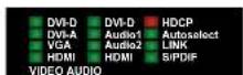
Detailed Example
flowchart
graph LR
    A["Laptop"] -->|VGA| B["UMX-OPT-TX150R"]
    C["Touch panel"] -->|RS 232| B
    D["Blu-Ray player"] -->|HDMI| B
    B -->|Fiber cable| E["HDMI-3D-OPT-RX150RA"]
    E -->|RS 232| F["Projector"]
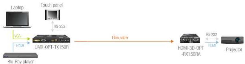
The system consists of the following: a Blu-Ray player and a laptop as sources, a programmable touch panel as a controller, then a Lightware UMX-OPT-TX150R and HDMI-3D-OPT-RX150R as the optical extenders, then a projector as a sink device. The touch panel has three buttons. The desired functions of the buttons are that they can power on and off the projector, and switch between the inputs. Let's examine the detailed solution.
Three types of the touch panel's commands:
(): settings of the touch panel / not sent /
[ ]: command to the projector / sent via RS-232 to UMX-OPT-TX150R then via fiber optical cable to the projector /
(): command to the UMX-OPT-TX150R / sent via RS-232 to UMX-OPT-TX150R /
Initializing:
First of all the touch panel can control the projector only if RS-232 settings are the same for the touch panel and the projector.
| Commands: | Comments: |
| (set_RS-232) | /* Set the appropriate RS-232 settings which are fit to the UMX-OPT-TX150R and the projector as well. */ |
| INFO: 57600, 38400, 19200 or 9600 Baud, 8 bit, 1stop bit, no parity. These settings are fit to the UMX-OPT-TX150R. | |
Button 1 (Power on the projector):
The touch panel can control the projector only if the UMX-OPT-TX150R is in pass-through mode.
| Commands:{RS232=PASS}[projector_on] | Comments:/* Set the UMX-OPT-TX150R in pass-through mode *//* Power on the projector */ |
Button 2 (Select the HDMI input):
The touch panel can only control the UMX-OPT-TX150R if that is in control mode.
| Commands:{RS232=CONTROL}{4@1 AV} | Comments:/* Set the UMX-OPT-TX150R in control mode *//* Select the HDMI input on the UMX-OPT-TX150R */ |
Button 3 (Power off the projector):
The touch panel can control the projector only if the UMX-OPT-TX150R is in pass-through mode.
| Commands:{RS232=PASS}[projector_off] | Comments:/* Set the UMX-OPT-TX150R in pass-through mode *//* Power off the projector */ |


- Software Control - Lightware Device Controller UMX-OPT-TX150R - User's Manual 26
5
Software Control – Lightware Device Controller
The device can be controlled by a computer through the USB port Lightware Device Controller (LDC). The software can be installed on a Windows PC or Mac OS X. The application and the User's Manual can be downloaded from www.lightware.eu. The Windows and the Mac versions have the same look and functionality.
INSTALL AND UPGRADE
▶ ESTABLISHING THE CONNECTION
▶ CROSSPOINT MENU
▶ INPUT PARAMETERS SETTINGS WINDOW
▶ OUTPUT PARAMETERS SETTINGS WINDOW
▶ EDID MENU
▶ SETTINGS MENU
▶ TERMINAL WINDOW
The device can be controlled using the Lightware Device Controller (LDC) from a Windows PC or laptop through USB and RS-232 port. The software can be installed on a Windows PC or Mac OS X. The application and the User's manual can be downloaded from www.lightware.eu. The Windows and the Mac versions have the same look and functionality.
The device can be controlled by a computer through the Ethernet and RS-232 port using Lightware Device Controller (LDC). The software can be installed on a Windows PC or Mac OS X. The application and the User's manual can be downloaded from www.lightware.eu. The Windows and the Mac versions have the same look and functionality.
5.1. Install and Upgrade
Installation for Windows OS
Run the installer. If the User Account Control drops a pop-up message click Yes.
During the installation you will be prompted to select the type of the installation: normal and the snapshot install:
| Normal install Snapshot install | |
| Available for Windows and Mac OS X | Available for Windows |
| The installer can update only this instance | Cannot be updated |
| Only one updateable instance can exist for all users | More than one different version can be installed for all users |
Comparison of installation types
ATTENTION! Using the Normal install as the default choice is highly recommended.
Installation for Mac OS X
INFO: After the installation, the Windows and the Mac application has the same look and functionality. This type of the installer is equal with the Normal install in case of Windows and results an updateable version with the same attributes.
Mount the DMG file with double clicking on it and drag the LDC icon over the Applications icon to copy the program into the Applications folder. If you want to copy the LDC into another location just drag the icon over the desired folder.
Upgrading of LDC
Step 1. Run the application.
The Device Discovery window appears automatically and the program checks the available updates on Lightware's website and opens the update window if the LDC found updates.
The current and the update version number can be seen at the top of the window and they are shown in this window even with the snapshot install.
text_image
Information Current version: 1.12 (6) Update version: 1.14 (6) Options Check for update automatically Framidal mini here Newtime New versions Setup Check now Download and update PreviewStep 2. Set the desired update setting in the Options section.
- If you do not want to check for the updates automatically, uncheck the circle, which contains the green tick.
- If you want to postpone the update, a reminder can be set with different delays from the drop down list.
- If the proxy settings traverse the update process, set the proper values then click the OK button.
Step 3. Click the Download update button to start the upgrading.
The updates can be checked manually by clicking the Check now button.
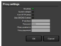
text_image
Proxy settings No proxy System default Use HTTP proxy Use BOOKS proxy Proxy host: Proxy port: 0016 Proxy default: Proxy password: OK Cancel5.2. Establishing the Connection
Step 1. Connect the device to a computer via USB or RS-232.
Step 2. Run the controller software; device discovery window appears automatically.
Step 3. Select the unit from the discovered USB devices or under Serial devices; when the device is connected through RS-232 click on the Query button next to the desired serial port to display the device's name and serial number. Double click on the transmitter or select the device and click on the Connect button.

text_image
LIGHTWARE Product name USB Devices Serial number USB Device ID Serial Number OK Cancel Enter CancelDevice Discovery Window in LDC
INFO: Lightware Device Controller software can only connect to the extender if it is in control mode. If the UMX-CPT-TX150R is in pass-through mode, the software cannot communicate with it and cannot list it as an available device. If you want to connect to the extender which is in pass-through mode, see details Set the RS-232 Operation Mode section.
5.3. Crosspoint Menu
When LDC finds the hardware, it determines the product type, and the LDC starts with the default page, showing the Crosspoint menu.
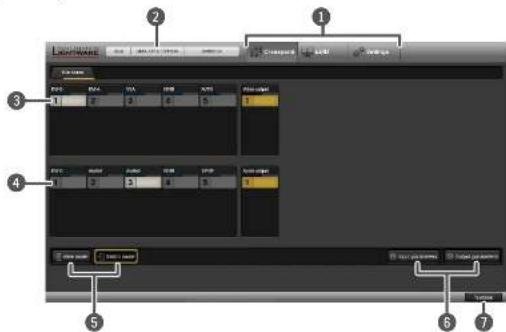
text_image
LocalWave 1 2 3 4 5 6 7 8 9 10 11 12 13 14 15 16 17 18 19 20 21 22 23 24 25 26 27 28 29 30 31 32 33 34 35 36 37 38 39 40 41 42 43 44 45 46 47 48 49 50 51 52 53 54 55 56 57 58 59 60 61 62 63 64 65 66 67 68 69 70 71 72 73 74 75 76 77 78 79 801 Main menu The available menu items are displayed. The active one is showed with dark grey background color.
2 Information ribbon The label shows the device label and serial number. Device discovery window can be displayed by clicking on this ribbon.
3 Video input ports Each tile represents a video input port. The tile below the port shows the current crosspoint setting; if the port is switched to the output, the color of the tile is white, otherwise grey.
4 Audio input ports Each tile represents an audio input port. The tile below the port shows current crosspoint setting; if the port is switched to the output, the color of the tile is white, otherwise grey. Dark grey means the audio port is not allowed to embed in the current video input port.
5 View mode/ Switch mode In View mode crosspoints settings are not modifiable, in Switch mode the input port is changeable. Yellow frame shows the current setting.
6 Input/Output parameters Clicking on this button opens the actual video and audio port properties window.
7 Terminal Clicking on this button opens the Terminal window where the device can be controlled through LW2 protocol commands.


- Software Control - Lightware Device Controller UMX-OPT-TX150R - User's Manual 28
5.4. Input Parameters Settings Window
By clicking on the Input parameters button a dialog window appears showing the parameters for the active input. This section shows the available settings and status information by port types.
5.4.1. Reload Factory Defaults
Current input: Reloads the default values to the currently selected input.
5.4.2. General Settings
HDCP Enable
The HDCP capability can be enabled or disabled on the input port with using the HDCP enable check box. This can prevent unnecessary HDCP encryption with certain source devices. Note that only unprotected content can be played on the source if this setting is disabled. For more information about HDCP handling see HDCP Management section.
No Sync Color
The port generates a solid 640x480 resolution image when there is no incoming signal and the No Sync enable check box is marked. The color of this picture can be set here. Double click on the colored field, a new window will appear. Choose the desired color then click the OK button to apply changes. Click the Cancel button to discard changes and close the window.
This function is available also with protocol command (see in Set the No Sync Picture Properties section).
No Sync Enable
If the No Sync enable check box is marked the port generates a solid 640x480 resolution image when there is no incoming signal. If the check box is unmarked and there is no incoming signal the device does not give the video signal and the hotplug on the output.
The service menu (Set the RS-232 Operation Mode section) allows enabling or disabling this function but only for all the input ports (the color set is not allowed in the service menu).
INFO: Audio transmission is available with video transmission only. If the No sync picture is disabled the audio transmission is available with valid incoming video signal only.
5.4.3. Input Port Status
Connection status of the selected input port is shown here. (Type of the video signal, HDCP encryption, the source 5V, sync type)
INFO: These fields are filled automatically by the device after the examination of the signal.
5.4.4. Video Signal Info
Resolution, color depth and colorspace of the incoming signal are shown here.
The 'Timing type' and 'Timing ID' fields show which parameters are used to digitize the incoming analog signal. The input port measures the incoming analog signal and determines the timings. If the parameters need adjustment, it can be done on the right side at 'analog options'. In this case the 'Timing ID' field changes to 'user modified' unless the parameters are not saved.
INFO: These fields are filled automatically by the device after the examination of the signal.
5.4.5. Audio Signal Info
Information about the embedded audio signal is shown here (Audio signal, audio type, sampling frequency, channel allocation). INFO: These fields are filled automatically by the device after the examination of the signal.
5.4.6. Analog Video Options
Analog video signals are digitized on the input. The timing parameters can be adjusted here if needed. Timing presets can be saved for each resolution separately.
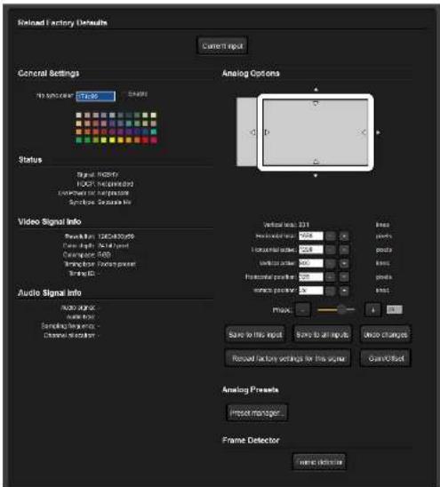
text_image
Reload Factory Defaults Current Input General Settings In Top view: TC36 Status Signal intensity 100% (Unspecified) Unknown for passengers Syncope Separate Info Video Signal info Revelation: 120x100x20 Case: High 120x100x20 Cancipase: 500 Transitions: None present Timing: 0 Audio Signal info Audio signal: Audio type: Serial frequency: Channel frequency: Analog Options Vertical axis: 331 Horizontal axis: 924 Horizontal position: 208 Vertical action: 300 Horizontal position: 300 Vertical position: 300 Linear Linear position: 924 Linear position: 208 Linear position: 300 Linear position: 300 Linear position: 300 Linear position: 300 Linear position: 300 Linear position: 300 Linear position: 300 Linear position: 300 Linear position: 300 Linear position: 300 Linear position: 300 Linear position: 300 Linear position: 300 Linear position : 1 Linear position : 1 Linear position : 1 Linear position : 1 Linear position : 1 Linear position : 1 Linear position : 1 Linear position : 1 Linear position : 1 Linear position : 1 Linear position : 1 Linear position : 1 Linear position : 1 Linear position : 1 Linear position : 1 Linear position : 1 Linear position : 1 Linear position : Linear position : Linear position : Linear position : Linear position : Linear position : Linear position : Linear position : Linear position : Linear position : Linear position : Linear position : Linear position : Linear position : Linear position : Linear position : Linear position : Linear position : Linear position : Linear position : Linear position : Linear position : Linear position : Linear position : Linear position : Linear position : Linear position : Linear position : Linear position : Linear position : Linear position : Linear position : Linear position : Linear position : Line: Line: Line: Line: Line: Line: Line: Line: Line: Line: Line: Line: Line: Line: Line: Line: Line: Line: Line: Line: Line: Line: Line: Line: Line: Line: Line: Line: Line: Line: Line: Line: Line: Line: Line: Line: Line: Line: Line: Line: Line: Line: Line: Line: Line: Line: Line: Line: Line: Line: Line:


- Software Control - Lightware Device Controller UMX-OPT-TX150R - User's Manual 29
Screen Position
Screen position is an easy way to fit the visible area of the analog video signal and the sink device. Actually the horizontal and vertical positions (Horizontal position and Vertical position) can be set with two different methods:
- Click on the arrows to increase or decrease the H.Pos and V.Pos values, or
- Move the mouse over the visible (grey) area. Click and hold with the left mouse button. Drag the visible area to the desired position.
Analog Video Timings
Vertical total: Total line number of the whole image. (The visible and the blanking area)
Horizontal total: Total pixel number of the whole image. (The visible and the blanking area)
Horizontal active: Pixel number of the visible image.
Vertical active: Line number of the visible image.
Horizontal Vertical position: Horizontal and vertical position values specify the location of the visible area on the sink device. Black border on any side of the picture can means wrong settings for the position of the visible area.
Phase: In case of unclear picture changing pixel phase can solve the problem. Changing the source device or the cable can cause pixel phase shifting.
Presets
User's settings for analog video
timings can be set into the
UMX-OPT-TX150R as presets.
One preset contains the following values which can be set by the user: Horizontal active, Vertical active, Horizontal position, Vertical position and Phase.
Presets can be assigned for each different resolution to the actual or to all inputs.
Save to this input: Preset assigned for the current resolution will be set to the actual input.
Save to all inputs: Preset assigned for the current resolution will be set to all inputs.
Undo changes: Backup the last saved preset values. If there were no saved values it sets up the original settings.
Reload factory settings for this signal: Clear the saved preset for this resolution from all the inputs, and sets up the original settings.
Analog Gain / Offset
Analog gain / offset window allows users to correct the gain and the offset values if the automatic mode doesn't give a good result. Gain and offset settings method are the same:
Step 1. Select the manual mode if the settings need to be changed.
Step 2. Tick the Lock channels if the three components might change with the same extent.
Step 3. Use the mouse to drag the slider and set to the desired position.
Step 4. Click on the Save button to store the changes.
Preset Manager
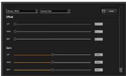
text_image
Symbol Offset Symbol Gain Offset GND GND GND Gain GND Gain Gain GainUser can handle the saved values with the built-in preset manager. Click on the Preset manager... button and a new window will open. Presets are showed for the actual input port. Delete record from this port: Delete the selected preset from only the current port.
Delete record from all ports: Don't need to open every preset manager for each input port to delete an unwanted preset. Just click the Delete record from all ports button. Never mind if the selected preset has different number in the other input properties list, because the device search by the current resolution.
Clone record to all port: Don't need to reload the saved values and save to all port. It can be done with only one step. Just select the desired
preset and click the Clone record to all port button.
Columns: User can select which fields will be shown for the saved presets. The default fields are: Name, V.freq, H.freq, V.pos, H.pos, V.size, H.size and Phase.
INFO: Analog timing presets can be saved only for the analog input port so Delete record from all ports and Clone record to all port buttons are kept for compatibility reasons.
5.4.7. Frame Detector
Click the frame detector button to view the measured detailed timings on the incoming signal.
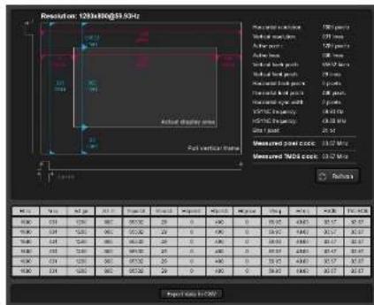
text_image
Resolution: 120x100x53.94 Actual display area Full vertical frame Measured data area Virtual display area Active display area Virtual display area Measured data area Virtual display area Measured data area VISTA Frequency VISTA Frequency Data point Measured data area Measured data area Measured data area Output Data (120x100x53.94) ResultsThe dark grey zone is the blanking area (non-visible) and the light gray colored zone is the picture (visible area).
INFO: Resolution is given by the source devices always means the picture (visible area) resolution and the refresh rate means the VSYNC frequency.
If the Refresh button is clicked on then the UMX-OPT-TX150R samples and calculates the analog signal values again.


- Software Control - Lightware Device Controller UMX-OPT-TX150R - User's Manual 30
Click on the Close button to close the Frame detector window and step back to the current input port settings window.
INFO: The frame detector only gives information about video signal from the selected input.
5.5. Output Parameters Settings Window
By clicking on the Video parameter label a dialog window appears showing the parameters for the corresponding output.
5.5.1. Set Signal Properties
Mode
The Mode can be set to Auto, DVI, HDMI, HDMI 30 bit DC, HDMI 36 bit DC. The Auto option sets the signal mode regarding to the attached display device's EDID and the incoming signal.
HDCP
The HDCP option sets the HDCP encryption on the output. The Auto setting applies encryption when the incoming signal is encrypted. The Always setting forces encryption on any incoming video signal.
5.5.2. General
Information about the signal and the connection status is shown here.
INFO: These fields are filled automatically by the device after the examination of the signal.
5.5.3. Display
Information retrieved from the connected display's EDID is shown.
INFO: These fields are filled automatically by the device after the examination of the signal.
5.5.4. Supported Audio Formats
The connected display's supported audio Formats are shown based on the read EDID.
5.5.5. Autoselect Settings
Video Auto Select
The video Autoselect settings are available in this drop-down menu. It can be:
• NonPriority, First detect,
• DVI-D priority or
- HDMI priority.
For detailed description about video Autoselect please read Video Autoselect Mode chapter.
Audio Auto Select
the audio Autoselect settings are available in this drop-down menu. can be:
• Static select (Digital + embedded, DVI-A + Audio 1, VGA + Audio 2),
- First detect (Embedded, S/PDIF, Analog 2),
• Priority detect (Embedded, S/PDIF, Analog 2),
• Priority detect (S/PDIF, Embedded, Analog 2),
• Priority detect (Embedded, Analog 2),
• Priority detect (S/PDIF, Analog 2),
• Fix select (Embedded),
• Fix select (Analog 1),
• Fix select (Analog 2),
- Fix select (S/PDIF),
For detailed description about audio Autoselect please read Audio Autoselect Mode chapter.
5.5.6. Optical Module Properties
Optical parameters give information about the device's optical module and the type of the connector.
INFO: These fields are filled automatically by the device after the examination of the signal.


- Software Control - Lightware Device Controller UMX-OPT-TX150R - User's Manual 31
5.6. EDID Menu
EDID management can be accessed by selecting the EDID menu. There are two panels: left one contains Source EDIDs, right one contains Destination places where the EDIDs can be emulated or copied.
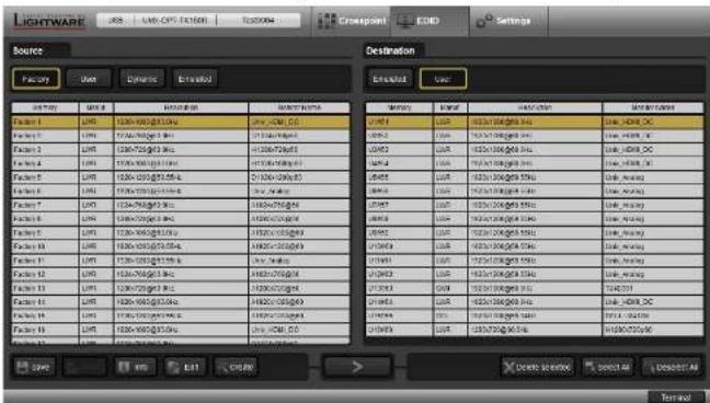
text_image
LIGHTWARE Source Destination Factory User Details Enrolled Enrolled User File Edit Operation New Items File1 File2 File3 File4 File5 File6 File7 File8 File9 File10 File11 File12 File13 File14 File15 File16 File17 File18 File19 File20 File21 File22 File23 File24 File25 File26 File27 File28 File29 File30 File31 File32 File33 File34 File35 File36 File37 File38 File39 File40 File41 File42 File43 File44 File45 File46 File47 File48 File49 File50 File51 File52 File53 File54 File55 File56 File57 File58 File59 File60 File61 File62 File63 File64 File65 File66 File67 File68 File69 File70 File71 File72 File73 File74 File75 File76 File77 File78 File79 File80 File81 File82 File83 File84 File85 File86 File87 File88 File89 File90 File91 File92 File93 File94 File95 File96 File97 File98 File99 File100Control Buttons

Save
Exporting an EDID
(save to a file)


Uploa
Importing an EDID
(load from a file)

Delete selected
Executing EDID
emulation or copying
(Transfer button)
Deleting EDID (from
User memory)

Info
Display EDID
Summary window
Opening Advanced
EDID Editor with the selected EDID

Derelect All
Selecting all memory
places in the right panel
Selecting none of the
memory places in the right panel

Creat
Opening Easy EDID
Creator
5.6.1. EDID Operations
After the list is downloaded, the current status is shown. The EDID memory consists of four parts.
The Emulated EDID List shows the currently emulated EDIDs for each input. It contains the input description, manufacturer, resolution, monitor name, source name for each input separately. The source column displays the memory location that the current EDID was routed from.
The Dynamic EDID List contains the resolution, manufacturer and vendor name of the display devices connected to device's output. The device remembers the last display device's EDID, so there is an EDID shown even if there is no device attached to the transmitter's output at the moment.
The Factory EDID List shows the factory memory locations (01# - 20#) with preprogrammed EDID.
The User EDID List shows the memory locations (51# - 66#) which can be used by the user to save custom EDIDs.
Any source reads the EDID from the Emulated EDID memory for the corresponding port. The user can select an EDID with the rotary switches to the desired input's memory location. This is called EDID switching. There are two types of the emulation: static and dynamic.
- Static EDID emulation happens, when an EDID from the Factory or User EDID list is selected by the Rotary switches (#1...#). In this case the Emulated EDID will remain the same until the user emulates another EDID.
- Dynamic EDID emulation can be enabled by selecting #0 on the EDID Rotary switch. The attached monitor's EDID is copied to the INPUT, if a new monitor is attached to the output, the emulated EDID changes automatically.
Changing Emulated EDID
To change the emulated EDID use the EDID Rotary switches on the rear panel of the device. For more information see EDIDs Are Referred with Rotary Switches chapter.
INFO: If dynamic emulation is established, the emulated EDID will be changed on the input every time a new monitor is connected to the output. If the monitor is disconnected from the output, the last EDID remains emulated for the source. This feature helps especially rental technicians or system integrators to keep the source continuously transmitting the signal, and adopt the system for new incoming display devices.
INFO: Power ON/OFF cycle will not affect the emulated EDID or other settings.
INFO: EDID routing procedure causes a status change, hence it is reported back to the control software within 2-3 seconds.
Learning an EDID
The system is able to learn the EDID from a connected display device and store it in one of the user programmable memory locations.
Step 1. Select the Dynamic EDID list from the Source panel (line will be highlighted with yellow).
Step 2. Select the User EDID list from the Destination panel (line will be highlighted with yellow).
Step 3. Press ➤ button to save the EDID into the selected User memory.


- Software Control - Lightware Device Controller UMX-OPT-TX150R - User's Manual 32
Exporting an EDID
Source EDID can be downloaded as a file (*.bin, *.dat or *.edid) to the computer.
Step 1. Select the desired EDID from the Source panel (line will be highlighted with yellow).
Step 2. Press the Save button to open the dialog box and save the file to the computer.
Importing an EDID
Previously saved EDID (*.bin, *.dat or *.edid file) can be uploaded to the user memory:
Step 1. Press the User button on the top of the Source panel and select a memory slot.
Step 2. Press the Upload button below the Source panel.
Step 3. Browse the file in the opening window then press the Open button. Browsed EDID is imported into the selected User memory.
ATTENTION! The imported EDID overwrites the selected memory place even if it is not empty.
Deleting EDID(s)
The EDID(s) from User memory can be deleted as follows:
Step 1. Press User button on the top of the Destination panel.
Step 2. Select the desired memory slot(s); one or more can be selected (Select All and Select None buttons can be used). The EDID(s) will be highlighted with yellow.
Step 3. Press the Delete selected button to delete the EDID(s).
5.6.2. EDID Summary Window
Select an EDID from Source panel and press Info button to display EDID summary.
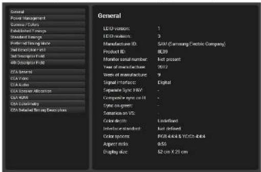
text_image
General Power Management Cable Colors Established Elements Standard Elements Color of Green Mode Metal Emitter Mode 3rd Description Field 4th Description Field CEA General CEA Vase CEA Active CEA Sensitive Allocation CEA R/W CEA Connectivity CEA Detailed Timing Description LED version: 1 LED output: 3 Manufacturer ID: SAM (Samsung Electric Company) Product ID: 8209 Monitor signal number: Not present Year of manufacture: 2017 Week of manufacture: 9 Signal Interface: Digital Separate Sync HVV: - Composable system on H: Sync on green: - Saturation on VS: - Color depth: Inner/Red Interface standard: Not defined Color spores: RGB 4x44 & YO/O 4x44 Aspect mix: 0.56 Display size: 82 cm X 29 cm
Save

Upload

Delete selected
5.6.3. Editing an EDID
Select an EDID from Source panel and press Edit button to display Advanced EDID Editor window. The editor can read and write all descriptors, which are defined in the standards, including the additional CEA extensions. Any EDID from the device's memory or a saved EDID file can be loaded into the editor. The software resolves the raw EDID and displays it as readable information to the user. All descriptors can be edited, and saved in an EDID file, or uploaded to the User memory. For more details about EDID Editor please visit our website (www.lightware.eu) and download EDID Editor user's manual.

Edit
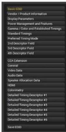
text_image
Basic EBITD Vendor / Product Information Display Parameters Power Management and Features Gamma / Color and Established Timings Standard Timings Preferred Timing Mode 2nd Descriptor Field 3rd Descriptor Field 4th Descriptor Field CEA Extension General Video Data Audio Data Speaker Allocation Data HDMI Colonometry Detailed Timing Descriptor #1 Detailed Timing Descriptor #2 Detailed Timing Descriptor #3 Detailed Timing Descriptor #4 Detailed Timing Descriptor #5 Detailed Timing Descriptor #6 Save EBITDEDID Byte Editor
| 0 | 1 | 2 | 3 | 4 | 5 | 6 | 7 | 8 | 9 | |
| 0 | 00 | FF | FF | FF | FF | FF | FF | 00 | 4C | 2D |
| 10 | 8E | 09 | 00 | 00 | 00 | 00 | 09 | 16 | 01 | 03 |
| 20 | 80 | 34 | 1D | 78 | 0A | 7D | D1 | A4 | 56 | 50 |
| 30 | A1 | 28 | 0F | 50 | 54 | 6D | EF | 80 | 71 | 4F |
| 40 | 81 | C0 | 81 | 00 | 81 | 80 | 95 | 00 | A9 | C0 |
| 50 | 83 | 00 | 01 | 01 | 02 | 3A | 80 | 18 | 71 | 38 |
| 60 | 2D | 40 | 58 | 2C | 45 | 00 | 09 | 25 | 21 | 00 |
| 70 | 00 | 1E | 66 | 21 | 56 | AA | 51 | 00 | 1E | 30 |
| 80 | 46 | 8F | 33 | 00 | 09 | 25 | 21 | 00 | 00 | 1E |
| 90 | 00 | 00 | 00 | FD | 00 | 18 | 4B | 1A | 51 | 17 |
| 100 | 00 | 0A | 20 | 20 | 20 | 20 | 20 | 20 | 00 | 00 |
| 110 | 00 | FC | 00 | 54 | 32 | 34 | 42 | 33 | 30 | 31 |
| 120 | 0A | 20 | 20 | 20 | 20 | 20 | 01 | 6C |


- Software Control - Lightware Device Controller UMX-OPT-TX150R - User's Manual 33
5.6.4. Creating an EDID
Since above mentioned Advanced EDID Editor needs more complex knowledge about EDID, Lightware introduced a wizard-like interface for fast and easy EDID creation. With Easy EDID Creator it is possible to create custom EDIDs in four simple steps. By clicking on the Create button below Source panel, Easy EDID Creator is opened in a new window. For more details about EDID Editor please visit our website (www.lightware.eu) and download EDID Editor user's manual.

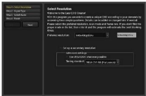
text_image
Select Resolution Welcome to the Copy CDU Creator With the program you are able to create a unique CDU according to your scheme by sonoring three simple questions. Details can be added or changed after if needed. Please select the preferred resolution, scan mode and frame rate. If you don't find the proper mode in the list, then create it and the program will estimate the best listening times. Preference resolution: 640-800-50Hz Setting Time Set up a secondary resolution Advanced settings Low VISA CDU otherwise possible Timing standard: VISA CDU RIS (Full period)5.7. Settings Menu
5.7.1. Device Information
The serial number, installed firmware version and the hardware revision of the device is shown under the Device Information tab.
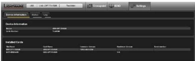
text_image
LIGHTWARE USB USB OPT EX/DDR Text2004 COSPRINT EOD Settings Device Information Status Log Device Information Device Name: USB OPT EX/DDR System Number: TOMEN Installed Cards Site Name: Card Name: Information Status: Address Status: System Number: USB OPT EX/DDR USB OPT EX/DDR URL: 10001-10001 URL: 10001-10001 URL: 10001-10001 URL: 10001-10001 URL: 10001-10001 URL: 10001-100015.7.2. Status
The current temperature of the device is displayed on Status tab.
5.7.3. Log
Events logged by the device and report generators can be found on Log tab. There are two sections: Report and Log viewer.
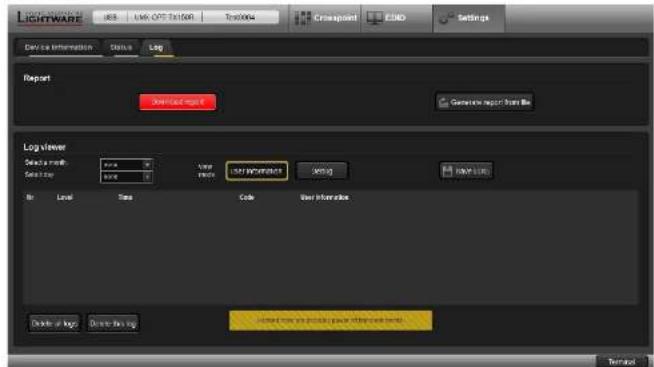
text_image
LIGHTWARE LOG - LVM CPG Editor Log/Info Cnspapoint CUBO Settings Device information Status Log Report Download log:1 Generate report from file Log Viewer Device mode value 0.00 Save Phone LOG REFERENCE Setting Log View No Level Time Code User Interaction Delete or log Delete from log Selected from your product power information table Send to you,请单击右键菜单Report Section
LDC is able to collect information from the device and save it to a report file. This information package can be sent to Lightware support team when a problem may arise with the device.
Download report
LDC collects the needed information; this may take up to a few minutes.
After generating the report, a Save as dialog box appears. Select the folder where you want to save the report file. The default file name can be changed.
The report contains the following device-dependent information (if available):
• Device type and serial number,
- Firmware version,
- All EDID headers and status (emulated, dynamic, factory, user).


- Software Control - Lightware Device Controller UMX-OPT-TX150R - User's Manual 34
Generate Report From File
The LDC is able to send a custom command file to UMX-OPT-TX150R. The command file can be generated by Lightware support. This is needed when some special commands have to be used for configuring the device or troubleshooting.
If a command file was sent:
Step 1. Save it to the computer.
Step 2. Click to the Generate report from file button. A browser window will be opened.
Step 3. Choose the command file. Another browser window will be appeared where the generated result file will be saved.
INFO: This function is only for special troubleshooting cases.
Log Viewer Section
Log files saved by the transmitter can be downloaded and viewed with this function.
User information is selected in the view mode (frame is highlighted with yellow), the columns in the list are the followings: error level, time (nominal time to give information about the order of the events), error code, user information.
The data is displayed in a structured, user-friendly way, this mode is recommended.
When Debug view mode is selected (frame is highlighted with yellow) there are some additional columns: error parameter, processor task identifier, occurrences and extra information. This data display for special troubleshooting cases.
The error log can be saved in a CSV file on the computer by the Export to CSV file button.
5.8. Terminal Window
This general purpose terminal is intended mainly for testing and debugging purposes. All commands can be used here that are discussed in the programmer's reference. The command text can be typed directly.
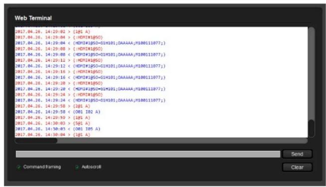
text_image
Web Terminal 2017.04.26, 14:29:02 > [1g1 A] 2017.04.26, 14:29:04 > (HDMI#1g5G) 2017.04.26, 14:29:04 < (HDMI#1g5G+01H101;OAAAAA,P100111077;} 2017.04.26, 14:29:08 > (HDMI#1g5G) 2017.04.26, 14:29:08 < (HDMI#1g5G+01H101;OAAAAA,P100111077;} 2017.04.26, 14:29:12 > (HDMI#1g5G) 2017.04.26, 14:29:12 < (HDMI#1g5G+01H101;OAAAAA,P100111077;} 2017.04.26, 14:29:16 > (HDMI#1g5G) 2017.04.26, 14:29:16 < (HDMI#1g5G+01H101;OAAAAA,P100111077;} 2017.04.26, 14:29:20 > (HDMI#1g5G) 2017.04.26, 14:29:20 < (HDMI#1g5G+01H101;OAAAAA,P100111077;} 2017.04.26, 14:29:24 > (HDMI#1g5G) 2017.04.26, 14:29:24 < (HDMI#1g5G+01H101;OAAAAA,P100111077;} 2017.04.26, 14:29:58 > [2g1 A] 2017.04.26, 14:29:58 < (OB1 102 A) 2017.04.26, 14:29:59 > [1g1 A] 2017.04.26, 14:30:03 > [5g1 A] 2017.04.26, 14:30:03 < (OB1 105 A) 2017.04.26, 14:30:04 > [5g1 A]By default commands are automatically surrounded by framing brackets. Every sent command and every received response gets an arrow (-> or <-) prefix, and has different font colors in order to help to distinguish.
The timecode in every row shows the exact time when the command was sent or the response received.
If the Command framing check box is unchecked, you can send multiple commands together, however in this case you have to type in the framing brackets manually.
The terminal can be also opened after starting the LDC - press the Terminal button on the Device discovery page on the bottom of the window.
TIPS AND TRICKS: The typed commands can be "browsed" when the cursor is in the command line and you press the up button on the keyboard. The commands are stored until the LDC is closed.

LW2 Programmers' Reference
Lightware UMX-OPT-TX150R can be controlled with external devices which can communicate according to the extender protocol. The supported LW2 commands are described in this chapter.
▶ SERIAL PORT SETTINGS
LW2 PROTOCOL DESCRIPTION
STATUS AND IDENTIFICATION COMMANDS
▶ SYSTEM COMMANDS
▶ EDID ROUTER COMMANDS
CONTROL COMMANDS
▶ ERROR LOG RELATED COMMANDS
▶ INPUT PROPERTIES
▶ OUTPUT PROPERTIES
▶ ERROR RESPONSES
▶ LW2 COMMANDS - QUICK SUMMARY
6.1. Serial Port Settings
UMX-OPT-TX150R uses RS-232 communication port. D-SUB connector pin assignments can be found in RS-232 Port chapter. The device uses standard RS-232 interface with the following default settings:
57600 Baud, 8 data bit, 1 stop bit, no parity
The serial port baud rate can be changed with rear panel rotary switch (Speed of the Serial Communication section) or protocol command - in case of #0 BAUD RATE rotary state (Change RS-232 Baud Rate section).
6.2. LW2 Protocol Description
The devices accept commands surrounded by curly brackets - {} - and responds with data surrounded by round brackets - () - only if a command was successfully executed. All input commands are converted to uppercase, but respond commands can contain upper and lower case letters as well.
| Format Explanation | |
| Input number in 1 or 2 digit ASCII Format (01, 5, 07, 16, etc.) | |
| Output number in 1 or 2 digit ASCII Format | |
| Input number in 2 digit ASCII Format (01, 02, 10, 12 etc.) | |
| Output number in 2 digit ASCII Format (01, 02, 10, 12 etc.) | |
| Location number in 1, 2 or 3 digit ASCII Format | |
| ID number in 1 or 2 digit ASCII Format | |
| ID number in 2 digit ASCII Format | |
| Italic parameters are optional | |
| CrLf Carriage | return, Line feed (0x0D, 0x0A) |
| ● | Space character (0x20) |
| → | Each command issued by the controller |
| ← | Each response received from the transmitter |


- LW2 Programmers' Reference UMX-OPT-TX150R - User's Manual 36
6.3. Status and Identification Commands
6.3.1. View Product Type
Description: Identification of the device. Type 'I' or 'I' then the transmitter responds its name.
| Format Example | |
| Command (I) | → (i) |
| Response (.)CrLf | ← (I:UMX-OPT-TX150R)CrLf |
Legend:
Explanation: The connected device is a UMX-OPT-TX150R.
6.3.2. View Serial Number
Description: The extender responds its 8-digit serial number.
| Format Example | |
| Command {S} | {s} |
| Response(>)CrLf | ← (SN:10170321)CrLf |
Legend:
Explanation: The connected device's serial number is 10170321.
INFO: Only the last 4 numbers are written onto the back of the transmitter.
6.3.3. View Firmware Version of the CPU
Description: View the CPU firmware revision.
| Format Example | |
| Command {F} | {f} |
| Response (FW:CrLf | ← (FW:1.0.4b1 r255r)CrLf |
Legend: string which may indicate special versions. =r indicates standard version.
Explanation: The connected device's firmware version is 1.0.4b1.
6.3.4. View Installed Controllers' Firmware
Description: Shows the firmware revisions of the installed controllers.
| Format Example | |
| Command {FC} | {fc} |
| Response (CF●END)CrLf | (CF END)CrLf |
Explanation: There is no installed controller. This command is reserved for compatibility reasons.
6.3.5. View Device's Temperature
Description: Queries temperature status.
| Format Example | |
| Command (ST)Response (ST•CPU•<DESC>•<TEMP>)CrLf | → (st)← (ST CPU N/A N/A N/A N/A N/A 29.4C)CrLf |
Legend:
Explanation: Internal temperature is 29.4 Celsius.
6.3.6. View CPU Firmware Compile Time
Description: Shows the CPU firmware compile time.
| Format Example | |
| Command (CT)Response (Compiled:••Build:•Crl.f | → {ct}← (Compiled: Sep 12 2014 11:58:00 Build:1)Crl.f |
Legend:
Explanation: The firmware was made in 12.09.2014, 11:58:00 and the identification number of the firmware is 1.
6.3.7. View Installed I/O Boards
Description: Shows the hardware name and revision of the installed cards. The number of responses varies regarding the frame size (number of slots).
| Format Example | |
| Command (IS) | {is} |
| Response (Sl.#●0●CrLf(SL●END)CrLf | (SL# 0 UMX-OPT-TX150R V11) CrLf (SL END) CrLf |
Legend: Slot 0 represents the motherboard.
Explanation: The extender reports that it has one motherboard called UMX-OPT-TX150R and its version number is V11.


- LW2 Programmers' Reference UMX-OPT-TX150R - User's Manual 37
6.3.8. Query All Port Status
Description: Shows the actual status of all input and output ports.
| Format Example | |
| Command {PS} | {ps} |
| Response (PS•,)CrLf | (PS 0000,0)CrLf |
Legend:
The input and output state tables are separated with a comma ",* character.
Explanation: This command is reserved for compatibility reasons.
6.4. System Commands
6.4.1. Query Current Control Protocol
Description: Shows the control protocol.
| Format Example | |
| Command {P_?} | → {p_?} |
| Response {(CURRENT●PROTOCOL●==.# <x}) CrLf | ← {(CURRENT PROTOCOL = #1)CrLf |
Legend:
Explanation: Protocol 1 is active here.
INFO: User can query the protocol only. This command is reserved for compatibility reasons.
6.4.2. Change RS-232 Baud Rate
ATTENTION! LW2 commands modify the baud rate only if the rotary switch is set #0. In other case the LW2 commands do not change the baud rate. From #1 to #9 the setting can be read from the state of the rotary switch (for more details see Speed of the Serial Communication section).
Description: The RS-232 baud rate can be set when the BAUD RATE rotary has #0 (software set) state. The command has to be sent with the earlier baud rate but the response comes with the new baud rate.
| Format Example | |
| Command {RS232BAUD=} | → {RS232BAUD=9600} |
| Response {RS232BAUD=}CrLf | ← {(RS232BAUD=9600)CrLf} |
Explanation: The device RS-232 port is set to 9600 baud.
Possible settings:
| Baud rate | |
| 9600 | 9600 baud |
| 19200 | 19200 baud |
| 38400 | 38400 baud |
| 57600 | 57600 baud |
| 115200 | 115200 baud |
6.4.3. Query RS-232 Baud Rate
ATTENTION! LW2 commands modify the baud rate only if the rotary switch is set #0. In other case the LW2 commands do not change the baud rate. From #1 to #9 the setting can be read from the state of the rotary switch For more details see Speed of the Serial Communication chapter.
Description: The RS-232 baud rate can be checked. It works via RS-232 as well, but if it is used the command has to be sent with the appropriate baud rate.
| Format Example | |
| Command {RS232BAUD=?}Response {RS232BAUD=<rate>)CrLf | → {RS232BAUD=?}← {(RS232BAUD=57600)CrLf |
Legend: Please read Change RS-232 Baud Rate.
Explanation: The device communicates with 57600 baud on the RS-232 port.
6.4.4. Reload Factory Defaults
Description: Factory default settings can be reloaded for different functions separately. Multiple functions can be entered.
| Format Example | |
| Command {FACTORY=...CrLf(FACTORY•<f2...)CrLf...(FACTORY•<fx...)CrLf | → {factory=xpoint;iocards;edidmem}← (FACTORY IOCARD...)CrLf← (FACTORY XPOINT...) CrLf← (FACTORY EDIDMEM...) CrLf |
Legend:
| Restores Factory Settings to | Additional response | |
| XPOINT Crosspoint table and configuration none | ||
| GENERAL Elevalsend, RS-232 working mode, baud rate none | ||
| IOCARDS All I/O settings | none | |
| EDIDMEM Clear User and Dynamic EDIDs | (DE_OK)(E_SW_OK)....(E_SW_OK) | |
| ALL | Restores all of the factory settings listed above | none |
Explanation: Factory default settings reloaded for crosspoint and I/O card configurations and emulated EDIDs.
INFO: The response may contain additional messages as the transmitter makes the configurations. These responses can be omitted.
INFO: After resetting the needed parameters, the device restarts. In case of USB connection reconnecting is always necessary.
WARNING! Reloading GENERAL factory defaults AFFECTS the serial operation mode and the RS-232 baud rate options as well. The default operation mode is the PASS mode and the default baud rate is 57600 baud in the UMX-OPT-TX150R. If the previous serial settings differ from the default ones, please set up the necessary values after reboot with protocol commands.
6.4.5. Set the RS-232 Operation Mode
Description: This command sets the RS-232 port operation mode.
| Format Example | |
| Command (RS232=) | → {rs232=control} |
| Response (RS232=<mode>)CrLf | ← (RS232=CONTROL)CrLf |
Legend:
Explanation: The device can be controlled via RS-232 port.
6.4.6. Query the RS-232 Operation Mode
Description: This command queries the current RS-232 operation mode.
| Format Example | |
| Command {RS232=?} | → {rs232=?} |
| Response {RS232=.)CrLf | ← {(RS232=PASS)CrLf |
Legend:
Explanation: The device can be controlled via RS-232 port.
6.4.7. Clear HDCP Key Cache
Description: The device stores the HDCP keys from the connected devices. These cached keys can be cleared with this command.
| Format Example | |
| Command {HDCPRESET} | → {hdcpreset} |
| Response (Done)CrLf | ← (Done)CrLf |
Explanation: HDCP key cache is cleared.
INFO: This function is useful when too many keys were cached and a connected source device cannot accept so many keys.


- LW2 Programmers' Reference UMX-OPT-TX15CR - User's Manual 39
6.4.8. Count HDCP Keys
Description: If there is an HDCP source on the HDMI input of the device, the device can ask the source whether it can handle
| Format Example | |
| Command:{HDCPTEST@}Response {HDCPTEST=CrLf | →:{hdcptest4@9}← {(HDCPTEST=SUCCESS)CrLf |
Legend:
SUCCESS: The source on the
FAIL: The source on the
UNAVAILABLE: If the
NOAUTH: If the
Explanation: The source on the 4th input can handle 9 HDCP sink devices.
6.4.9. Restart Transmitter
Description: The extender can be restarted without unplugging power.
| Format Example | |
| Command {RST} | {rst} |
| Response (Booting...)CrLf | ← (Booting...)CrLf |
| (●READY!)CrLf | ← (UMX-OPT-TX150R READY!) |
Legend:
Explanation: The extender reboots and sends a message when it is ready.
INFO: The response can be seen only if the connection to the extender via RS-232 is still alive. The response cannot be seen and reconnect is always necessary in case of USB connection.
6.4.10. View Error List
Description: Shows the basic error list since last boot up.
| Format Example | |
| Command {ELIST=?}Response (ELIST#<num>●●●●●●●●●●●●●●●●●●●●●●●●●●●●●●●●●●●●●●●●●●●●●●●●●●●●●●●●●●●●●●●●●●●●●●●●●●●●●●●●●●●●●●●●●●●●●●●●●●●●○●●●●●●●●●●●●●●●●●●●●●●●●●●●●●●●●●●●●●●●●●●●●●●●●●●●●●●●●●●●●●●●●●●●●●●●●●●●●●●●●●●●●●●●●●●●●●●●●●●● ●●●●●●●●●●●●●●●●●●●●●●●●●●●●●●●●●●●●●●●●●●●●●●●●●●●●●●●●●●●●●●●●●●●●●●●●●●●●●●●●●●●●●●●●●●●●●●●●●●●● | → {elist=?}← {ELIST#1 Notice BOOTp:6 o:1)CrLf← {ELIST#2 Notice READY p:0 o:1)CrLf← {ELIST#1 Notice BOOTp:6 o:1)CrLf← {ELIST#2 Notice READY p:0 o:1)CrLf |
Legend:
NOTICE: The number of the HDCP keys.
WARNING: Possible problem without influencing normal operation.
MATTER: Problem that may lead to further errors.
ERROR: Serious error. Must report to support.
FATAL: Fatal error. Normal operation is not possible.
short name for type of log entry
technical parameter
Explanation: There are no errors only standard notices that occur on boot up.
INFO: The error list can contain Notices and Warnings under normal operation. These entries do not mean that there is any problem with the transmitter!
6.4.11. Configure Remote Alerts
Description: The device logs different levels of errors. Configure which level of errors has to be sent out as an alarm message.
| Format Example | |
| Command ELEVELSEND#<p>=<0>,<1>,<2>,<3>,<4>}Response (ELEVELSEND#<p>=<0>,<1>,<2>,<3>,<4>)CrlF | → {ELEVELSEND#1=0,0,1,1,1}← {ELEVELSEND#1=0,0,1,1,1)CrlF |
Legend:
Adjusted control interface must be 1 = RS-232
| <0> | NOTICE level events | 0 = no immediate message send | ||||
| 1 | = | immediate | message | |||
| <1> | WARNING level events | 0 = no immediate message send | ||||
| 1 | = | immediate | message | |||
| <2> | MATTER level events | 0 = no immediate message send | ||||
| 1 | = | immediate | message | |||
| <3> | ERROR level events | 0 = no immediate message send | ||||
| 1 | = | immediate | message | |||
| <4> | FATAL level events | 0 = no immediate message send | ||||
| 1 | = | immediate | message | |||
Explanation: The device will send an immediate message on all control interfaces when a MATTER, ERROR or FATAL level error occurs.
6.4.12. Query Level of Remote Alerts
Description: User can check which level of errors has to be sent out as an alarm message.
| Format Example | |
| Command {ELEVELSEND#=>?} | → {ELEVELSEND#1=?} |
| Response {ELEVELSEND#<=0>,<1>,<2>,<3>,<4>)CrLf | ← (ELEVELSEND#1=0,0,1,1,1) CrLf |
Legend: Please read Configure Remote Alerts section.
Explanation: The device will send an immediate message on all control interfaces when a MATTER, ERROR or FATAL level error occurs.
6.4.13. Set the Video Priority Settings
Description: This command sets the video priority order of the Autoselect mode.
| Format Example | |
| Command (VIDEOPRIORITY=) | (videopriority=4) |
| Response (VIDEOPRIORITY=)CrLf | (VIDEOPRIORITY=4)CrLf |
Legend:
<0> First detect (factory default)
First the device check the DVI-D than VGA than the HDMI video input port. That port will be selected which contains valid video signal.
<1> DVI-D priority If there is a valid signal on the DVI-D input, this port always will be selected, even if the active port was the VGA or the HDMI input port.
<4> HDMI priority
If there is a valid signal on the HDMI input, this port always will be selected, even if the active port was the VGA, DVI-A or the DVI-D input port.
Explanation: The device uses HDMI priority in the Autoselect mode.
Please see the detailed information in Video Autoselect Mode section.
6.4.14. Query the Video Priority Settings
Description: This command queries the video priority mode.
| Format Example | |
| Command {VIDEOPRIORITY=?} | {videopriority=?} |
| Response (VIDEOPRIORITY=)CrLf | {(VIDEOPRIORITY=1)CrLf} |
Legend: Please read Set the Video Priority Settings section.
Explanation: The device uses DVI-D priority in the Autoselect mode.


- LW2 Programmers' Reference UMX-OPT-TX150R - User's Manual 41
6.4.15. Set the Audio Priority Settings
Description: This command sets the audio priority order of the Autoselect mode.
| Format Example | |
| Command {AUDIOPRIORITY=} | {audiopriority=1} |
| Response {AUDIOPRIORITY=<apmode>)CrLf | (AUDIOPRIORITY=1)CrLf |
Legend:
<[]>
Static select: Digital+Embedded, DVI-A+Analog1, VGA+Analog2
<1> First detect: Embedded, S/PDIF, Analog 2
<2> Priority: Embedded, S/PDIF, Analog 2
<3> Priority: S/PDIF, Embedded, Analog 2
<4> Priority: Embedded, Analog 2
<5> Priority: S/PDIF, Analog 2
Fix select: Embedded
Fix select: Analog 1
Fix select: Analog 2
Fix select: S/PDIF
Explanation: The device uses the first detect method in the Autoselect mode.
Please see Audio Autoselect Mode section for detailed information about audio Autoselect.
6.4.16. Query the Audio Priority Settings
Description: This command queries the audio priority mode.
Format Example Command {AUDIOPRIORITY=?}Response (AUDIOPRIORITY=)CrLf {audiopriority=?}← (AUDIOPRIORITY=0)CrLf
Legend: Please read Set the Audio Priority Settings section.
Explanation: The device uses the static select method in the Autoselect mode.
6.5. EDID Router Commands
The EDID router manipulates the EDID memory, which has memory locations that are assigned to specific input or output ports. For more details please read EDID Memory Structure section.
ATTENTION! Emulated EDIDs can be switched with the rotary switches only.
6.5.1. Save EDID to User Memory (Learn EDID)
Description: Learn EDID from to .
Format Example Command <> → {u3:d1} Response (E_SW_OK)Crlf ← (E_SW_OK)Crlf (E_S_C) Crlf ← (E_S_C)Crlf
Legend: has to be 'Uxx'.
can be 'Fxx' or 'Uxx' or 'Dxx'.
Explanation: EDID from the output 1 is saved to user EDID #3.
INFO: The transmitter sends (E\_S\_C) only if the new EDID is different from the earlier one.
6.5.2. View Emulated EDIDs on All Inputs
Description: Shows the currently emulated EDIDs for all the inputs. The value at the given index (, , , ) shows which EDID is used on that particular input.
Format Example Command {VEDID} {vedid} Response (VEDID•<in1>•<in2>•<in3>•<in4>)CrLf (VEDID F005 D001 U001 U002)CrLf
Legend: All indexes show a which was copied to that input port.
Explanation: F005 (Factory preset EDID F05) is emulated on the input 1. EDID from output is dynamically emulated on input 2. First and the second User EDID are emulated on input 3 and input 4.
6.5.3. Watch EDID Validity Table
Description: Shows EDID validity table, which contains information about the EDID memory states.
Format Example Command {WV} {wv*} Response {EV• ← (EVU 31111111111111111)CrLf .)CrLf ← (EVD 1)CrLf← (EVE 1111)CrLf
Legend:
Response length F Factory preset EDIDs 20 U User saved EDIDs 16 D Dynamic EDIDs 1 E Emulated EDIDs 4 * All U, D and E EDIDs


6. LW2 Programmers' Reference UMX-OPT-TX150R - User's Manual 42
INFO: can be only capital letter.
Each number represents the EDID validity state for the corresponding memory location.
Value Description 0 Invalid EDID 1 Valid EDID 3 Changed EDID
Explanation: There is one '3' in the first row on the 1st position. This means that the user EDID is changed since the last EDID query on that port.
INFO: If a changed EDID is queried by the {WH} command (see the next section), its value returns to '1'.
INFO: EDID deleting means the universal EDID will be uploaded to the deleted EDID's place.
6.5.4. View EDID Header
Description: Shows basic information about EDIDs in the memory.
Format Example Command {WH} → {whe1} Response {EH#••<EDID_HEADER>)Crlf ← {(EH#E1 LWR 1920x1080@60HzUniv_HDMI_DC)Crlf
Legend: Depending on the query can be for one EDID, all EDID in the block.
Fxx Factory EDID query header for one EDID Uxx User EDID query Dxx Dynamic EDID query Exx Emulated EDID query F^ All Factory preset EDIDs headers for all (20) Factory EDIDs U* All User saved EDIDs headers for all (16) user EDIDs D* All Dynamic EDIDs header from the output (1) E^ All Emulated EDIDs headers from all the four inputs (4)
consists of 3 fields separated by spaces:
PNPID code: The three letter abbreviation of the manufacturer
Preferred resolution: The resolution and refresh rate stored in the preferred detailed timing block.
Name: The name of display device stored in product descriptor.
Explanation: Shows the EDID from the input 1
6.5.5. Download EDID Content from the Transmitter
Description: EDID hex bytes can be read directly. The transmitter will issue the whole content of the EDID present on memory location (256 bytes).
Format Example Command {WE}Response (EB#<loc>●<B1>●<B2>●...●<B256>)Crlf → {wef1}← (EB#F1 00 FF FF FF FF FF 00 32 F2 00 00 00...... 00 92) Crlf
Legend: . are space separated hex characters represented in ASCII Format.
Explanation: Full EDID from memory location 1 is downloaded.
6.5.6. Upload EDID Content from the Transmitter
Description: EDID hex bytes can be written directly to the user programmable memory locations.
Sequence:
Step 1. Prepare the device to accept EDID bytes to the specified location with command {WL#}
Step 2. Device responds that it is ready to accept EDID bytes with (E\_L\_S)CrLf
Step 3. Send 1 block of EDID (1 block consist of 8 bytes of hex data represented in ASCII Format) with command: {WB#|B1>B2>B3>B4>B5>B6>B7>|B8>}
Step 4. The device acknowledges with response (EL#)
Step 5. Repeat steps 3 and 4 to send the remaining 31 blocks of EDID (32 altogether)
Step 6. After the last acknowledge, the device indicates that the EDID status changed by sending (E\_S\_C) CrLf
Format Example Command {WL#}Response (E_L_S)CrlfCommand {WB#1•<B1>•<B2>•<B3>•<B4>•<B5>•<B6>•<B7>•<B8}>Response (EL#<num>)CrlfCommand {WB#2•<B9>•<B10>•<B11>•<B12>•<B13>•<B14>•<B15><B16>}Response (EL#<num>) CrLf...Command {WB#32•<B249>•<B250>•<B251>•<B252>•<B253>•<B254>•<B255>•<B256>}Response (EL#<num>) CrLfResponse (E_S_C) CrLf → {wl#u3}← {E_L_S) CrLf→ {wb#1 00 FF FF FF FF FF 00}← {EL#1)CrLf→ {wb#2 38 A3 8E 66 01 01 01}← {EL#2)CrLf...→ {wb#32 36 59 42 0A 20 20 00 96}← {EL#32)CrLf← {E_S_C)CrLf
Legend: represents the sequential number of every 8 byte part of EDID. is between 1 and 32. .. are the bytes of EDID.
Explanation: Full EDID uploaded to memory location U3.
6.5.7. Delete EDID from Memory
Description: Clear EDID from memory location .
Format Example Command {DE} → {deu3} Response (E_SW_OK)Crlf ← (E_SW_OK)Crlf (DE_OK)Crlf ← (DE_OK)Crlf (E_S_C)Crlf ← (DE_OK)Crlf
Legend: Depending on , one EDID, or all EDIDs in a block can be cleared.
Result Fxx Not valid! Factory EDID cannot be deleted. No response. Uxx Specified User EDID is deleted. Dxx Dynamic EDID is the Universal EDID by factory default and it cannot be deleted. Exx Specified Emulated EDID is selected by a rotary switch and it cannot be deleted. F* Not valid! Factory EDID cannot be deleted. No response. U* All User EDIDs are deleted. D* UMX-OPT-TX150R contains only one Dynamic EDID and it cannot be deleted.. E* All Emulated EDIDs are selected by rotary switches and they cannot be deleted.
Explanation: Third user EDID is cleared from memory.
INFO: Only user EDIDs can be deleted. Deleting means the factory EDID (Universal HDMI or Analog EDID) will be loaded into the desired user EDID memory.
6.6. Control Commands
Description: The following commands with option can take effect in multiple layers, according to their parameters. Depending on 'A' or 'V' it can change only the Audio, or only the Video layer; or 'AV' changes both.
INFO: option usually can be skipped for legacy purposes. In this case using router commands the router changes all (Video & Audio) layers, but using status commands it displays information about only the Video layer. Please use AV option, when available.
6.6.1. Switch One Input to One Output
Description: This command switches the output to an input.
Format Example Command {@@••}Response (O•••••A/V/AV>)CrLf → {2@1 av}← {(001 I02 AV)CrLf
Legend: :
Layer select:
A: Audio layer
V: Video layer
AV: Audio&Video layer
must be 1, 2, 3, 4 or 5 in case of video input
1: DVI-D video input
2: DVI-A video input
3: VGA video input
4: HDMI video input
5: Automatic source selection
must be 1, 2, 3, 4 or 5 in case of audio input
1: DVI-D embedded audio input
2: Analog audio 1 input
3: Analog audio 2 input
4: HDMI embedded audio input
5: S/PDIF audio input
must be 1
Explanation: The Example shows how to connect both Audio and Video from input 2 to output 1.
INFO: If the command is used without the parameter, video layer is switched.


6. LW2 Programmers' Reference UMX-OPT-TX150R - User's Manual 44
6.6.2. View All Connections on the Output
Description: This command displays the connections on a single or multiple layers.
Format Example Command {VC•<A/V/AV>}Response (ALLV•<in2>)CrLf(ALLA•<in2>)CrLf → {vc•av}← (ALLV•01)CrLf(ALLA•01)CrLf
Legend: Please read in Switch One Input to One Output section.
Explanation: The response contains all the connections, if both layers are selected the response is two messages. The Example shows that output 1 Audio & Video are connected to input 1 Audio & Video.
INFO: If the command is used without the parameter, the response shows only the video layer connections.
6.6.3. Query Autoselect State
Description: This command queries the actual state of the autoselect.
Format Example Command {AUTOSELECT=?} {autoselect=?} Response (AUTOSELECT=)CrLf (AUTOSELECT=3)CrLf
Legend: : The number of the selected input port:
S: Searching is in progress and there is no selected video input.
1: DVI-I input is selected.
3: VGA input is selected.
4: HDMI input is selected.
N/A: The device is not in autoselect mode.
Explanation: The device is in autoselect mode and the VGA input is selected.
6.7. Error Log Related Commands
UMX-OPT-TX150R logs the error events into an EPROM memory. The device emulates a standard FAT16 file system with a fix directory and file structure.
M:\LOG\1970\_01\1.CSV
M:\ virtual drive letter, root directory
LOG directory
1970\_01 directory, contains the log file
1.CSV the log file (Format of the log file is CSV - comma separated values)
INFO: The drive letter, directory names and file names are given with upper case and the commands are case sensitive.
6.7.1. List a Directory
Description: List the content of a directory.
Format Example Command {SD_DIR= → {sd_dir=M:\LOG} Response {(DIR1•<cont>)CrLf ← {(DIR1 1970_01)CrLf (DIR_END)CrLf ← {(DIR_END)CrLf
Legend: : The path of the directory with absolute reference. There are only two directory: LOG and 1970\_01 and the drive letter is always M:\.
: The content of the given directory.
Explanation: LOG directory contains the 1970\_01 directory.
6.7.2. List the Log File
Description: The command lists the saved error events. The log file is always available.
Format Example Command {SD_GETT=M:\LOG\1970_01\1.CSV}Response (LOG#1...)CrLf(LOG#2...)CrLf(LOG●END)CrLf → {SD_GETT=M:\LOG\1970_01\1.CSV}← (LOG#1 level(time;code;param;task;occurency;info)CrLf← (LOG END)CrLf
Legend: LOG#1 The header of the log file.
LOG#x Every LOG# row is different event.
Explanation: The log file doesn't contain any event. The header (LOG#1) is shown only.
6.7.3. Clear the Log File
Description: This command clears the error events but keeps the empty log file with header and the directory structure.
Format Example Command {SD_Format} → {sd_Format} Response (OK)CrLf ← (OK)CrLf
Explanation: The log file content is cleared.


6. LW2 Programmers' Reference UMX-OPT-TX150R - User's Manual 45
6.8. Input Properties
The following commands are setting up the properties of the input ports. If only one or a few parameters have to be modified, the protocol enables to mask the other parameters, so they can stay untouched. To mask a parameter use "x" or "X" as its value.
Example: {ANALOG#2@SI=x;x;x;x;210;x;} Only change the horizontal position on the input port 2.
INFO: If the input port is not a selected, active port and this port is affected by an input command the response will be N/A.
6.8.1. Set Input Port Properties
Description: This command queries the actual state of the autoselect.
Format Example Command {:DVII#@<S/A>|<=VIDEO><X1><X2><HDCP}Response {DVII#<in>@<S/A>|=<VIDEO><X.X;<HDCP><STATUS><SOURCE><ATIM1/DCS><ATIM2/DRES><ARES/HAUDIO><HASAMP><HCH>)Crlf → {:dvII#1@si=x;x;x;}← {DVII#1@SI=D;x;x;1,3;H;20,1920x1080p60;P;48;}Crlf
Legend: : Affected ports:
S = single selected input
A = all inputs
6.4.16. Query the Audio Priority Settings
Description: This command queries the audio priority mode.| Format Example | |
| Command {AUDIOPRIORITY=?}Response (AUDIOPRIORITY=)CrLf | {audiopriority=?}← (AUDIOPRIORITY=0)CrLf |
6.5. EDID Router Commands
The EDID router manipulates the EDID memory, which has memory locations that are assigned to specific input or output ports. For more details please read EDID Memory Structure section. ATTENTION! Emulated EDIDs can be switched with the rotary switches only.6.5.1. Save EDID to User Memory (Learn EDID)
Description: Learn EDID from| Format Example | |
| Command <> | → {u3:d1} |
| Response (E_SW_OK)Crlf | ← (E_SW_OK)Crlf |
| (E_S_C) Crlf | ← (E_S_C)Crlf |
6.5.2. View Emulated EDIDs on All Inputs
Description: Shows the currently emulated EDIDs for all the inputs. The value at the given index (| Format Example | |
| Command {VEDID} | {vedid} |
| Response (VEDID•<in1>•<in2>•<in3>•<in4>)CrLf | (VEDID F005 D001 U001 U002)CrLf |
6.5.3. Watch EDID Validity Table
Description: Shows EDID validity table, which contains information about the EDID memory states.| Format Example | |
| Command {WV} | {wv*} |
| Response {EV• | ← (EVU 31111111111111111)CrLf |
| .)CrLf | ← (EVD 1)CrLf← (EVE 1111)CrLf |
| Response length | ||
| F | Factory preset EDIDs | 20 |
| U | User saved EDIDs | 16 |
| D | Dynamic EDIDs | 1 |
| E | Emulated EDIDs | 4 |
| * | All U, D and E EDIDs |
| Value Description |
| 0 Invalid EDID |
| 1 Valid EDID |
| 3 Changed EDID |
6.5.4. View EDID Header
Description: Shows basic information about EDIDs in the memory.| Format Example | |
| Command {WH} | → {whe1} |
| Response {EH#••<EDID_HEADER>)Crlf | ← {(EH#E1 LWR 1920x1080@60HzUniv_HDMI_DC)Crlf |
| Fxx Factory EDID query | header for one EDID | |
| Uxx User EDID query | ||
| Dxx Dynamic EDID query | ||
| Exx | Emulated EDID query | |
| F^ | All Factory preset EDIDs | headers for all (20) Factory EDIDs |
| U* | All User saved EDIDs | headers for all (16) user EDIDs |
| D* | All Dynamic EDIDs | header from the output (1) |
| E^ | All Emulated EDIDs | headers from all the four inputs (4) |
6.5.5. Download EDID Content from the Transmitter
Description: EDID hex bytes can be read directly. The transmitter will issue the whole content of the EDID present on memory location| Format | Example |
| Command {WE}Response (EB#<loc>●<B1>●<B2>●...●<B256>)Crlf | → {wef1}← (EB#F1 00 FF FF FF FF FF 00 32 F2 00 00 00...... 00 92) Crlf |
6.5.6. Upload EDID Content from the Transmitter
Description: EDID hex bytes can be written directly to the user programmable memory locations. Sequence: Step 1. Prepare the device to accept EDID bytes to the specified location| Format Example | |
| Command {WL#}Response (E_L_S)CrlfCommand {WB#1•<B1>•<B2>•<B3>•<B4>•<B5>•<B6>•<B7>•<B8}>Response (EL#<num>)CrlfCommand {WB#2•<B9>•<B10>•<B11>•<B12>•<B13>•<B14>•<B15><B16>}Response (EL#<num>) CrLf...Command {WB#32•<B249>•<B250>•<B251>•<B252>•<B253>•<B254>•<B255>•<B256>}Response (EL#<num>) CrLfResponse (E_S_C) CrLf | → {wl#u3}← {E_L_S) CrLf→ {wb#1 00 FF FF FF FF FF 00}← {EL#1)CrLf→ {wb#2 38 A3 8E 66 01 01 01}← {EL#2)CrLf...→ {wb#32 36 59 42 0A 20 20 00 96}← {EL#32)CrLf← {E_S_C)CrLf |
6.5.7. Delete EDID from Memory
Description: Clear EDID from memory location| Format Example | |
| Command {DE} | → {deu3} |
| Response (E_SW_OK)Crlf | ← (E_SW_OK)Crlf |
| (DE_OK)Crlf | ← (DE_OK)Crlf |
| (E_S_C)Crlf | ← (DE_OK)Crlf |
| Result | |
| Fxx Not valid! Factory EDID cannot be deleted. No response. | |
| Uxx Specified User EDID is deleted. | |
| Dxx Dynamic EDID is the Universal EDID by factory default and it cannot be deleted. | |
| Exx Specified Emulated EDID is selected by a rotary switch and it cannot be deleted. | |
| F* Not valid! Factory EDID cannot be deleted. No response. | |
| U* All User EDIDs are deleted. | |
| D* UMX-OPT-TX150R contains only one Dynamic EDID and it cannot be deleted.. | |
| E* All Emulated EDIDs are selected by rotary switches and they cannot be deleted. | |
6.6. Control Commands
Description: The following commands with option can take effect in multiple layers, according to their parameters. Depending on 'A' or 'V' it can change only the Audio, or only the Video layer; or 'AV' changes both. INFO: option usually can be skipped for legacy purposes. In this case using router commands the router changes all (Video & Audio) layers, but using status commands it displays information about only the Video layer. Please use AV option, when available.6.6.1. Switch One Input to One Output
Description: This command switches the output to an input.| Format Example | |
| Command {@@••}Response (O•••••A/V/AV>)CrLf | → {2@1 av}← {(001 I02 AV)CrLf |
6.6.2. View All Connections on the Output
Description: This command displays the connections on a single or multiple layers.| Format Example | |
| Command {VC•<A/V/AV>}Response (ALLV•<in2>)CrLf(ALLA•<in2>)CrLf | → {vc•av}← (ALLV•01)CrLf(ALLA•01)CrLf |
6.6.3. Query Autoselect State
Description: This command queries the actual state of the autoselect.| Format Example | |
| Command {AUTOSELECT=?} | {autoselect=?} |
| Response (AUTOSELECT=)CrLf | (AUTOSELECT=3)CrLf |
6.7. Error Log Related Commands
UMX-OPT-TX150R logs the error events into an EPROM memory. The device emulates a standard FAT16 file system with a fix directory and file structure. M:\LOG\1970\_01\1.CSV M:\ virtual drive letter, root directory LOG directory 1970\_01 directory, contains the log file 1.CSV the log file (Format of the log file is CSV - comma separated values) INFO: The drive letter, directory names and file names are given with upper case and the commands are case sensitive.6.7.1. List a Directory
Description: List the content of a directory.| Format Example | |
| Command {SD_DIR= | → {sd_dir=M:\LOG} |
| Response {(DIR1•<cont>)CrLf | ← {(DIR1 1970_01)CrLf |
| (DIR_END)CrLf | ← {(DIR_END)CrLf |
6.7.2. List the Log File
Description: The command lists the saved error events. The log file is always available.| Format Example | |
| Command {SD_GETT=M:\LOG\1970_01\1.CSV}Response (LOG#1...)CrLf(LOG#2...)CrLf(LOG●END)CrLf | → {SD_GETT=M:\LOG\1970_01\1.CSV}← (LOG#1 level(time;code;param;task;occurency;info)CrLf← (LOG END)CrLf |
6.7.3. Clear the Log File
Description: This command clears the error events but keeps the empty log file with header and the directory structure.| Format Example | |||
| Command | {SD_Format} | → | {sd_Format} |
| Response (OK)CrLf | ← (OK)CrLf | ||
6.8. Input Properties
The following commands are setting up the properties of the input ports. If only one or a few parameters have to be modified, the protocol enables to mask the other parameters, so they can stay untouched. To mask a parameter use "x" or "X" as its value. Example: {ANALOG#2@SI=x;x;x;x;210;x;} Only change the horizontal position on the input port 2. INFO: If the input port is not a selected, active port and this port is affected by an input command the response will be N/A.6.8.1. Set Input Port Properties
Description: This command queries the actual state of the autoselect.| Format Example | |
| Command {:DVII#@<S/A>|<=VIDEO><X1><X2><HDCP}Response {DVII#<in>@<S/A>|=<VIDEO><X.X;<HDCP><STATUS><SOURCE><ATIM1/DCS><ATIM2/DRES><ARES/HAUDIO><HASAMP><HCH>)Crlf | → {:dvII#1@si=x;x;x;}← {DVII#1@SI=D;x;x;1,3;H;20,1920x1080p60;P;48;}Crlf |