DP-OPT-RX150 - Audio/video extender Lightware - Free user manual and instructions
Find the device manual for free DP-OPT-RX150 Lightware in PDF.


User questions about DP-OPT-RX150 Lightware
0 question about this device. Answer the ones you know or ask your own.
Ask a new question about this device
Download the instructions for your Audio/video extender in PDF format for free! Find your manual DP-OPT-RX150 - Lightware and take your electronic device back in hand. On this page are published all the documents necessary for the use of your device. DP-OPT-RX150 by Lightware.
USER MANUAL DP-OPT-RX150 Lightware
visual engineering LIGHTWARE
User's Manual
text_image
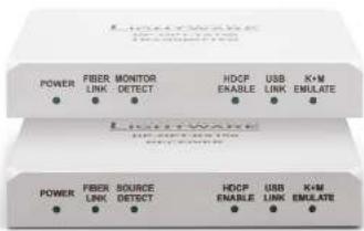
HKEYWAVE POWER FIBER MONITOR HDCF USB K+M LINK DETECT ENABLE LINK EMULATE Lightwave POWER FIBER SOURCE HDCF USB K+M LINK DETECT ENABLE LINK EMULATEDP-OPT-TX150
DP-OPT-RX150
Fiber Optical Multimedia Extender


DP-OPT-TX150, DP-OPT-RX150 - User's Manual 2
Important Safety Instructions
To disconnect the equipment safely from power, remove the power cord from the rear of the equipment, or from the power source. The MAINS plug is used as the disconnect device, the disconnect device shall remain readily operable.
There are no user-serviceable parts inside of the unit. Removal of the cover will expose dangerous voltages. To avoid personal injury, do not remove the cover. Do not operate the unit without the cover installed.
The appliance must be safely connected to multimedia systems. Follow instructions described in this manual.
Ventilation
For the correct ventilation and to avoid overheating ensure enough free space around the appliance. Do not cover the appliance, let the ventilation holes free and never block or bypass the ventilators (if any).
WARNING
To prevent injury, the apparatus is recommended to securely attach to the floor/wall or mount in accordance with the installation instructions. The apparatus shall not be exposed to dripping or splashing and that no objects filled with liquids, such as vases, shall be placed on the apparatus. No naked flame sources, such as lighted candles, should be placed on the apparatus.
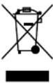
Waste Electrical & Electronic Equipment WEEE
This marking shown on the product or its literature, indicates that it should not be disposed with other household wastes at the end of its working life. To prevent possible harm to the environment or human health from uncontrolled waste disposal, please separate this from other types of wastes and recycle it responsibly to promote the sustainable reuse of material resources. Household users should contact either the retailer where they purchased this product, or their local government office, for details of where and how they can take this item for environmentally safe recycling. Business users should contact their supplier and check the terms and conditions of the purchase contract. This product should not be mixed with other commercial wastes for disposal.
Caution: Laser product

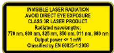
Common Safety Symbols
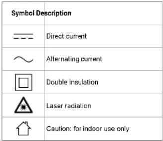 |


DP-OPT-TX150, DP-OPT-RX150 - User's Manual 3
Symbol Legend
The following symbols and markings are used in the document:
WARNING! Safety-related information which is highly recommended to read and keep in every case!
ATTENTION! Useful information to perform a successful procedure; it is recommended to read.
INFO: A notice which may contain additional information. Procedure can be successful without reading it.
DEFINITION: The short description of a feature or a function.
TIPS AND TRICKS: Ideas which you may have not known yet but can be useful.
Navigation Buttons
Go back to the previous page. If you clicked on a link previously, you can go back to the source page by clicking the button.
Navigate to the Table of Contents.
Step back one page.
Step forward to the next page.
Document Information
All presented functions refer to the indicated products. The descriptions have been made during testing these functions in accordance with the indicated Hardware/Firmware/Software environment:
| Item Version | |
| Lightware Device Controller (LDC) software 1.20.0 | |
| Lightware Device Updater Software 1.5.3 | |
| Controller firmware 1.1.11b0 | |
| Hardware v11 |
Document revision: 2.1
Release date: 30-10-2018
Editor: Laszlo Zsedenyi


DP-OPT-TX150, DP-OPT-RX150 - User's Manual 4
Table of Contents
- INTRODUCTION 5
1.1. DESCRIPTION....5 1.2. MODEL DENOMINATION....5
1.2. MODEL DENOMINATION ..... 5 1.3. BOX CONTENTS ..... 5
1.4 FEATURES OF THE DEVICE....5
1.5. TYPICAL APPLICATIONS ...... 6 - INSTALLATION....7
2.1. MOUNTING OPTIONS 7
2.1.1. Rack Shell Mounting 7 2.1.2. UD-kit Mounting 7
2.1.2. OD-RIT MOOUNTING 7 2.2. CONNECTING STEPS 7
2.3. SECURITY SLOT 7 - PRODUCT OVERVIEW 8
3.1. DP-OPT-TX150 8
3.2. DP-OPT-RX150 9
3.3.1. Fiber Optical Connector 9
3.3.2. DP Input and Output Ports 9
3.3.3. USB Connectors....9 - OPERATION ....10
4.1 POWERING ON 10
4.1.1. Setting up USB Devices.... 10 4.2. USB Maps.... 10
4.2.1. Changing the USB Mode 11
4.3. HDCP SETTING ....11
4.4. DP MODE AND HDMI MODE....11 - SOFTWARE CONTROL - LIGHTWARE DEVICE CONTOLLER
SOFTWARE....12
5.1. INSTALL AND UPGRADE 12
5.2. CONNECTING TO A DEVICE (DEVICE DISCOVERY WINDOW)....13
5.3. CONTROL MENU....13
5.3.1. Video and Link Panel 13 5.3.2. Transmitter Panel 14
5.3.2. Transmitter Panel 14 5.3.3. Receiver Panel 15
5.4. REAL-LIFE EXAMPLES (USB DEVICES AND MODES)....16
5.5. TERMINAL MENU 18
5.6. SETTINGS MENU 18
5.6.1. Device Information 18 5.6.2. Log Tab 19
3.0.2. Log Tab....19 - FIRMWARE UPGRADE....20
6.1. ABOUT THE FIRMWARE PACKAGE (LFP FILE)....20
6.2. SHORT INSTRUCTIONS....20
6.3. INSTALL AND UDRAPES....20
6.3. INSTALL AND OPGRADE 20
6.4. RETAILD INSTRUCTIONS 21
6.4.1. Establish the Connection 21
6.4.2. Start the LDU and Follow the Instructions 21
7. TROUBLESHOOTING....25
8. TECHNOLOGIES....26
8.1. HDCP MANAGEMENT....26
8.1.1. Protected and Unprotected Content 26
8.1.2. Real-life Examples 26
8.2. DISPLAYPORT....27
8.3.1. Dual mode....27
8.2.1. Dual mode 27
9. APPENDIX 28
9.1. SPECIFICATIONS 28
9.2. MECHANICAL DRAWINGS 29
9.3. FURTHER INFORMATION....30
1
Introduction
Thank You for choosing Lightware's DisplayPort Fiber Optical extender devices. In the first chapter we would like to introduce the device highlighting the most important features in the below listed sections:
DESCRIPTION
▶ MODEL DENOMINATION
Box CONTENTS
FEATURES OF THE DEVICE
▶ TYPICAL APPLICATIONS
1.1. Description
DisplayPort is one of the newest video interface standards. Using DisplayPort, high resolution video and excellent quality audio can be transmitted. The interface's 10.8 Gbps bandwidth is capable of transmitting 2560x1600@60Hz pixel resolution video with full support of content protection (HDCP). UHD and 4Kx2K resolution can be achieved up to 30Hz frame rate.
Intelligent HID Emulation is provided for two devices with full transparency. The special HID devices – including keyboard and mouse – are emulated by the extender and transparently transferred to the computer with the result that no extra drivers are required for the proper functionality, it's as easy as Plug & Play. DP-OPT-TX150 has 2 extra local USB ports with a built-in HUB and can be connected to the PC/Mac with a single USB cable.
When connecting a DVI or HDMI display through an adaptor cable, Dual-mode DisplayPort graphic cards reconfigure their outputs to DVI or HDMI accordingly. Lightware DisplayPort extenders support Dual-mode port extension and adaptor cables.
Lightware's DisplayPort extenders can be used with Thunderbolt sources and devices. The extender pair and the DisplayPort monitor have to be placed at the end of the Thunderbolt chain. Apple Thunderbolt Display is not supported.
Single Fiber Technology makes these units fully DisplayPort 1.1a and HDCP 1.1 compliant without the need of a second fiber cable or copper connections. To simplify cabling, the bidirectional communication - necessary for DisplayPort Link Training, HDCP handshaking and USB transfer - is performed on the same fiber core that transmits the video signal. Both receiver and transmitter are remote configurable from either side through the mini USB connector.
1.2. Model Denomination
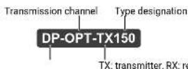
1.3. Box Contents
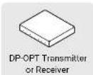
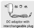

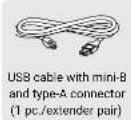
1.4. Features of the Device

Supports Highest Resolutions
Transmitting DisplayPort 1.1a video signals up to 10.8 Gbps bandwidth, e.g. 2560x1600 pixels at 60 Hz or 4096x2400 pixels at 30 Hz.

One Multimedia Fiber Cable
DisplayPort signal is transmitted using only one multimode 50/125 fiber optical cable with SC connector.

No Signal Latency With Zero Frame Delay
The signal management architecture ensures that there is no delay added between the input and the output.

Dual-mode DisplayPort
DVI or HDMI display device can be connected to DP-OPT-RX150 through a passive adaptor thus forces the source to send DVI/HDMI signal.

HDCP Enable/Disable
When the extenders are in HDMI mode, HDCP can be enabled or disabled to prevent unnecessary encryption to ensure compatibility.

USB KVM Extension
The source computer can be controlled remotely by USB HID devices (e.g. mouse, keyboard) connected to DP-OPT-RX150, as their signal is transmitted through the fiber cable.

USB 2.0 HUB
DP-OPT-TX150 connected to a computer via USB can be used as a local USB HUB with two USB 2.0 ports.

Thunderbolt
Sources with Thunderbolt port are also supported – just connect a miniDP-DP cable between the source and DP-OPT-TX150.

Front Panel LEDs
Immediate feedback about the status of connected DP source and monitor. Fiber link-, USB- and HDCP-status are also shown on the front panel.

USB Control
USB management, information about connected devices and firmware upgrade can be accessed with Lightware software via USB connection.

Universal Power Adaptor
Equipped with a universal +5V DC power adaptor, which accepts AC voltages from 100 to 240 Volts with 50 or 60 Hz line frequency.

Kensington Security Slot® Support
The security slot can be found on the side of the units for theft protection.
1.5. Typical Applications
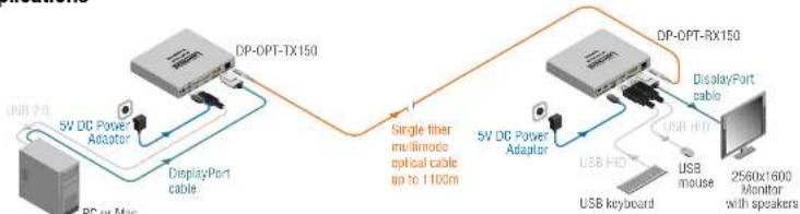
flowchart
```mermaid
graph LR
    A["DC Power Adapter"] --> B["DisplayPort cable"]
    B --> C["DP-OPT-TX150"]
    C --> D["Single fiber multimode optical cable go to 1100m"]
    D --> E["DP-OPT-RX150"]
    E --> F["DisplayPort cable"]
    F --> G["USB mouse"]
    G --> H["2560x1600 Monitor with speakers"]
    A --> I["PC or Mac"]
    I --> J["Low 2.0"]
    J --> K["5V DC Power Adaptor"]
    K --> L["DisplayPort cable"]
    L --> M["DB"]
Stand-alone Diagram with a High-resolution DP monitor
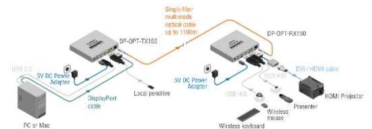
flowchart
graph LR
    A["PC or Mac"] -->|USB 2.0| B["5V DC Power Adaptor"]
    B --> C["DisplayPort cable"]
    C --> D["Local pendrive"]
    D --> E["DP-OPT-TX150"]
    E --> F["Single fiber multimode optical cable up to 1100m"]
    F --> G["DP-OPT-RX150"]
    G --> H["DVI / HDMI cable"]
    H --> I["HDMI Projector"]
    I --> J["Wireless mouse"]
    J --> K["USB HID"]
    K --> L["5V DC Power Adaptor"]
    L --> M["DisplayPort cable"]
    M --> N["Local pendrive"]
    N --> O["DP-OPT-TX150"]
    O --> P["Single fiber multimode optical cable up to 1100m"]
Stand-alone Diagram with an HDMI Projector
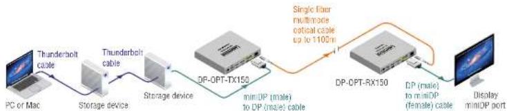
flowchart
graph LR
    PC["PC of Mac"] -->|Thunderbolt cable| StorageDevice["Storage device"]
    StorageDevice -->|Thunderbolt cable| StorageDevice
    StorageDevice -->|DP-OPT-TX150| DPOTTX150["min(DP (male) to DP (male) cable"]
    DPOT-TX150 -->|Single filter multimode optical cable up to 1100m| DPOTRX150
    DPOTRX150 -->|DP (male) to miniOP (female) cable| DisplayMiniOPPort["Display miniOP port"]
Daisy-chained Thunderbolt Devices and a LED Cinema Display


- Installation DP-OPT-TX150, DP-OPT-RX150 - User's Manual 7
2
Installation
The chapter is about the installation of the device and connecting to other appliances, presenting also the mounting options.
- MOUNTING OPTIONS
- CONNECTING STEPS
▶ SECURITY SLOT
2.1. Mounting Options
WARNING! For the correct ventilation and to avoid overheating ensure enough free space around the appliance and do not cover it. INFO: In order to get the necessary mounting accessory please contact sales@lightware.com.
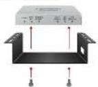
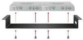
2.1.1. Rack Shelf Mounting
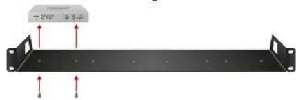
The 1U high rack shelf provides mounting holes for fastening four DP-OPT_150 extenders and put them into a standard rack cabinet (width of the Rack shelf is 448 mm – without the ears). Fix the device to the Rack shelf as shown in the figure:
text_image
三平闸 半多闸2.1.2. UD-kit Mounting
Mounting with UD-kit (Under desk)
Mounting with UD-kit Double (Under Desk Double)
2.2. Connecting Steps
flowchart
graph TD
    A["Laptop"] -->|USB| B["Router"]
    B -->|DP| A
    B -->|Power| C["External Device"]
    C -->|USB| D["Monitor"]
    D -->|DP or| B
    B -->|HDMI| E["Adaptor"]
    E -->|OPT| B
    B -->|Power| F["External Device"]
    F -->|USB| G["External Device"]
    G -->|USB| H["External Device"]
    style A fill:#f9f,stroke:#333
    style D fill:#f9f,stroke:#333
    style B fill:#ccf,stroke:#333
    style E fill:#ccf,stroke:#333
    style F fill:#cfc,stroke:#333
    style G fill:#cfc,stroke:#333
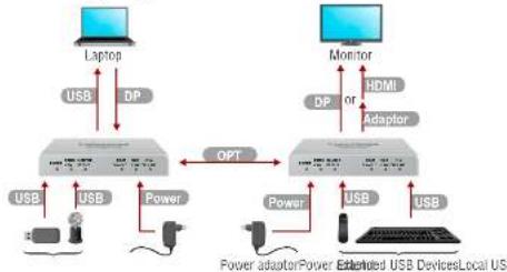
DP Connect the desired source to the DP input port of the transmitter.
USB Connect the supplied USB cable between the transmitter and a computer to extend USB HID devices, to connect local USB devices, and/or to control the extenders by LDC.
USB Connect the desired local USB devices to the Transmitter and USB HID devices to the Receiver for USB KVM extension.
DP Connect a DP sink device to the Receiver by a DP cable or an HDMI sink device by an HDMI cable and a DP/HDMI adaptor cable.
OPT Connect a multimode fiber optical cable between the Transmitter and the Receiver.
POWER Connect the power adaptor to the DC input on the receiver first, then to the AC power socket or use Lightware's rack-mountable Power Supply Units.
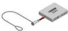
2.3. Security slot
A Kensington-compatible security slot can be found on the side of the units for theft protection. (Security cable is not supplied with the extenders.)
3
Product Overview
The following sections are about the physical structure of the device, input/output ports and connectors:
DP-OPT-TX150
DP-OPT-RX150
▶ ELECTRICAL CONNECTIONS
3.1. DP-OPT-TX150
Front View
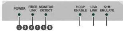
text_image
POWER FIBER LINK MONITOR DETECT 1 2 3 4 5 6 HDCP ENABLE USB LINK K+M EMULATE1 POWER LED
• ON: the unit is powered on.
- BLINKING: an error has occurred and device is out of normal operation, or it is in bootload mode (during firmware upgrade).
② FIBER LINK LED
- ON: the link is active between the extenders and ready to use.
- BLINKING: is no connection between the extenders.
3 MONITOR LED
• ON: a sink device is connected to the output port of the receiver.
4 HDCP LED
- ON: DP signal transmission is in progress or HDCP encryption is enabled during DVI/HDMI transmission.
- OFF: a DVI or HDMI display is connected to the receiver (via an adaptor cable) and HDCP is disabled (thus the source is forced to send non-encrypted stream). For more information about the HDCP setting, see the HDCP Setting section.
5 USB LINK LED
• ON: HID extension is active.
- BLINKING: the USB channel is ready to use but HID extension is not active (e.g. there is no USB HID device connected to the receiver or the computer is powered off).
• OFF: the USB channel between the extenders is not ready.
6 K+M EMULATE LED
- OFF: the transmitter is in transparent USB mode (default).
- BLINKING: the transmitter is in configuration USB mode; see the USB Modes section for more information.
Rear View
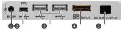
text_image
DC SV CPU 3 4 INPUT SC MN OUTPUT 1 2 51 DC Connector
Connect the output of the supplied +5 V power adaptor. Lightware's rack mountable power supply can also be used (PSUx10-200 or PSUx20-400).
2 Local USB Ports
The transmitter has a built-in USB HUB. These local USB 2.0 ports can be used as extra USB ports connected to your computer but without extension.
3 DisplayPort Input
DisplayPort 1.1a input connector. Applied cable shall not be more than 2 m. See the DP Input and Output Ports section for more information about the connector.
4 USB Connector
USB mini-B type connector. Connect to the computer if USB HUB or USB KVM (HID) features are used. Control functions (with Lightware Device Controller) and firmware upgrade are also performed through this connector.
5 SC Fiber Connector
SC fiber optical output connector. Connect to the receiver by a multimode fiber cable.
3.2. DP-OPT-RX150
Front View
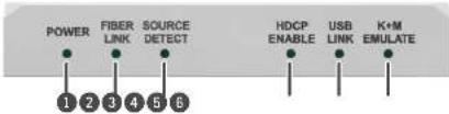
text_image
POWER FIBER LINK SOURCE DETECT 1 2 3 4 5 6 HDCP ENABLE USB LINK K+M EMULATE
POWER LED
• ON: the unit is powered on.
- BLINKING: an error has occurred and device is out of normal operation, or it is in bootload mode (during firmware upgrade).

FIBER LINK LED
- ON: the link is active between the extenders and ready to use.
- BLINKING: is no connection between the extenders.

SOURCE LED
- ON: powered DP source is connected to the transmitter.
- BLINKING: an HDMI adaptor cable is connected to the receiver to indicate HDMI mode operation.

HDCP LED
- ON: DP signal transmission is in progress or HDCP encryption is enabled during DVI/HDMI transmission.
- OFF: a DVI or HDMI display is connected to the receiver (via an adaptor cable) and HDCP is disabled (thus the source is forced to send non-encrypted stream). For more information about HDCP setting, see the HDCP Setting section.

USB LINK LED
• ON: HID extension is active.
- BLINKING: the USB channel is ready to use but HID extension is not active (e.g. there is no USB HID device connected to the receiver or the computer is powered off).
- OFF: the USB channel between the extenders is not ready.

K+M EMULATE LED
- OFF: the transmitter is in transparent USB mode (default).
- BLINKING: the transmitter is in configuration USB mode.
Rear View
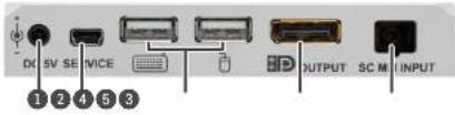
text_image
DC 5V SE SERVICE OUTPUT SC M INPUT 1 2 4 5 3
DC Connector
Connect the output of the supplied +5 V power adaptor. Lightware's rack mountable power supply can also be used (PSUx10-200 or PSUx20-400).

USB Ports
Ports for USB HID (Human Interface Device, e.g. mouse, keyboard, or presenter) and USB HUB devices (e.g. keyboard with built-in USB HUB). Only HID devices are extended to the source computer. (The symbols are just recommendations; mouse can be plugged into the port indicated with keyboard symbol and vice versa.)

DisplayPort
DisplayPort 1.1a output connector for display devices with DisplayPort connector. The applied DP-DP cable shall not be more than 2 m. DP adapters with DVI or HDMI connector are also supported. See the DP Input and Output Ports section for more information about the connector.

USB Connector
USB mini-B type connector for control functions (with Lightware Device Controller) and firmware upgrade.

SC Fiber
Connector
SC fiber optical input connector. Connect to the transmitter by a single multimode fiber cable.
3.3. Electrical Connections
3.3.1. Fiber Optical Connector
The extenders are assembled with standard SC receptacles.

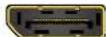
3.3.2. DP Input and Output Ports
DP-OPT-TX150 and DP-OPT-RX150 provides DisplayPort connectors with Dual-mode support. When a passive adapter is connected to the receiver, the source device is forced to switch to DVI/HDMI mode.
3.3.3. USB Connectors
Standard USB connectors are built in the extenders supporting different features, but the pinout of the connectors are the same.



Operation
This chapter is about the powering and operating of the device describing the video and USB functions:
POWERING ON
USB MODES
▶ HDCP SETTING
DP MODE AND HDMI MODE
4.1. Powering On
ATTENTION! When building an electronic system, make sure that all of the devices are powered down before connecting them. Powered on devices may have dangerous voltage levels which can damage sensitive electronic circuits.
After the system is complete, connect the DC power cable to the extender unit and then to the power outlet. The unit is immediately powered ON.
After the extender units are initialized, the attached DP source and monitor can be powered on.
ATTENTION! If the power LED does not light up upon power-up, the unit is most likely damaged and further use is not advised. Please contact support@lightware.com.
INFO: The laser becomes enabled any time the transmitter is powered on. This is done to avoid accidental laser loss problems.
4.1.1. Setting up USB Devices
DP-OPT-RX150 handles USB HID devices (Human Interface Device), which are input devices like mouse, keyboard, presenter, pointing device, etc. However USB HUBs are supported (like those keyboards, monitors that have built-in USB HUB), only two devices are available for extension at the same time.
When the transmitter is connected to the computer by the USB cable, it can be used as a local USB 2.0 HUB. To build the USB connection, do the following steps:
Step 1. Connect the supplied USB cable to the transmitter's mini USB connector.
Step 2. Connect the other end of the USB cable into an empty USB slot on the computer.
Step 3. Connect the HID device(s) to the receiver.
INFO: If the previously used USB devices are connected through the extenders to the computer, they may be handled as new hardware by the operating system at the first time.
4.2. USB Modes
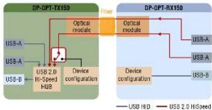
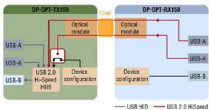
Two channels are used for the USB communication between the extenders. Channel A1 is always transparent and one USB HID device is always operable. The other channel's state can be set which determines the current USB mode.
Transparent USB Mode
Both channels are available for USB HID devices connected to the receiver. Default setting is transparent USB mode which means both USB HID devices connected to the receiver are transparently transmitted to the source computer.
flowchart
graph TD
    subgraph_DP-OPT-TX150["DP-OPT-TX150"]
        A["USB-A"] --> B["USB 2.0 Hi-Speed HUB"]
        C["USB-B"] --> B
        B --> D["Device configuration"]
        E["Optical module"] --> F["Optical module"]
        G["Sensor"] --> H["Sensor"]
    end

    subgraph_DP-OPT-RX150["DP-OPT-RX150"]
        I["USB-A"] --> J["USB 2.0 Hi-Speed"]
        K["USB-B"] --> J
        J --> L["Device configuration"]
        M["Sensor"] --> N["Sensor"]
    end

    style DP-OPT-TX150 fill:#f9f,stroke:#333
    style DP-OPT-RX150 fill:#bbf,stroke:#333
USB channels in Transparent mode
Configuration USB Mode
Configuration USB mode is an option where the extenders' USB settings can be configured by using the Lightware Device Controller. One channel (A1) is available for a USB HID device, the other channel (A2) is reserved for communication.
flowchart
graph LR
    subgraph DP-OPT-TX150
        A["USB-A"] --> B["USB-B"]
        C["USB-A 2.0 H-Speed HUB"] --> D["Device configuration"]
        E["Optical module"] --> F["Optical module"]
        G["Device configuration"] --> H["Device configuration"]
    end

    subgraph DP-OPT-RX150
        I["USB-A"] --> J["USB-B"]
        K["USB-A 2.0 H-Speed"] --> L["Device configuration"]
        M["Device configuration"] --> N["Device configuration"]
    end

    A --> C
    C --> D
    D --> E
    E --> G
    G --> H
    H --> I
    I --> J
    J --> K
    K --> L
    L --> M
USB channels in Configuration mode
INFO: The USB mode has an effect only on the transmitter's state. Receiver is always in configuration mode. Setting the USB mode on the receiver effects only the transmitter.


- Operation DP-OPT-TX150, DP-OPT-RX150 - User's Manual 11
4.2.1. Changing the USB Mode
The USB mode can be changed in the transmitter or in the receiver but in latter case make sure that the extenders are linked by the fiber cables.
ATTENTION! If the USB mode is changed in the receiver when the extenders are not connected by fiber cable, the setting is store in the receiver and the USB mode will be changed after reconnecting.
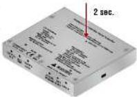
Step 1. Power ON the extender(s) and locate the hidden function button on the bottom side.
Step 2. Press and keep pressed the button by a thin tool (e.g. paper clip) for about two seconds. Release the button not more than five seconds.
Step 3. The current USB mode is visible on the front panel.
ATTENTION! When the configuration mode is active, only one USB HID device can be used: the one that was connected to the receiver at first.
INFO: Default setting (transparent mode) is restored when the device is powered on.
4.3. HDCP Setting
When a non-HDCP compatible sink is connected to the receiver, the source can be forced to output non-encrypted signal if the content is not protected. For more information about the HDCP management, see the HDCP Management section.
HDCP is enabled as a default setting but can be changed as follows:
Step 1. Locate the hidden function button on the bottom side of the extender (either on TX150 or RX150).
Step 2. Press and keep pressed the hidden function button by a thin tool (e.g. paper clip) for at least 10 seconds (pressing the button for a shorter period changes the US are in HDMI mode the 'HDC before releasing the button.
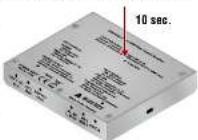
ATTENTION! The HDCP setting can be changed in DP mode, but in this case the 'HDCP enable' LED will not show the change. The setting will be effective only after switching to HDMI mode. In DP mode HDCP is always enabled.
INFO: The HDCP setting is available in both extenders.
4.4. DP Mode and HDMI Mode
The extenders work in two modes according to the connected display device:
DisplayPort Mode (DP-DP cable)
When the DP output port of the transmitter is connected to the DP input port of the display device, the extenders are in DP mode. In this case the source sends DP signal.
Display is Connected by a DVI/HDMI Passive Adaptor
When the DP output port of the transmitter is connected to the DVI/HDMI port of the display device through a passive adaptor, the extenders and the source are in HDMI mode. In this case the source sends DVI/HDMI signal. See more information about the Dual mode in the HDCP Setting section.
5
Software Control - Lightware Device Controller Software
The extenders can be controlled by a computer through the USB port using Lightware Device Controller (LDC). The software can be installed on a Windows PC or Mac OS X. The application can be downloaded from www.lightware.com. The Windows and the Mac versions have the same look and functionality.
INSTALL AND UPGRADE
- CONNECTING TO A DEVICE (DEVICE DISCOVERY WINDOW)
CONTROL MENU
REAL-LIFE EXAMPLES (USB DEVICES AND MODES)
▶ TERMINAL MENU
▶ SETTINGS MENU
5.1. Install and Upgrade
INFO: After the installation, the Windows and the Mac application has the same look and functionality. This type of the installer is equal with the Normal install in the case of Windows and results an updatable version with the same attributes.
Installation for Windows OS
Run the installer. If the User Account Control drops a pop-up message click Yes. During the installation you will be prompted to select the type of the installation: normal and the snapshot install:
| Normal install Snapshot install | |
| Available for Windows and Mac OS X | Available for Windows |
| The installer can update only this instance | Cannot be updated |
| Only one updateable instance can exist for all users | More than one different version can be installed for all users |
Comparison of the Installation Types
ATTENTION! Using the Normal install as the default option is highly recommended.
Installation for Mac OS X
Mount the DMG file with double clicking on it and drag the LDC icon over the Applications icon to copy the program into the Applications folder. If you want to copy the LDC into another location just drag the icon over the desired folder.
The Upgrading of the LDC
Step 1. Run the application.
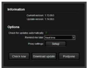
The Device Discovery window appears automatically and the program checks the available updates on Lightware's website and opens the update window if the LDC found updates. The current and the update version number can be seen at the top of the window and they are shown in this window even with the snapshot install. The Update window can be also opened by clicking the Ⓑ (About) and the Update button.
Step 2. Set the desired update setting in the Options section. When the Check for updates automatically option is selected, the LDC tries to find a new version after startup The update can be postponed by setting a reminder; use the drop down list. The proxy settings can be set in a separate window.
Step 3. Click the Download update button to start. The updates can be checked manually by clicking the Check now button.
text_image
Information Current version: 1.13.0b3 Update version: 1.14.0b3 Options Check for updates automatically: Remind me later Next time Proxy settings Setup Check now Download update PostponeTIPS AND TRICKS: To get the best visibility of the screenshots in this chapter adjust the zoom setting of your PDF Reader software to 150% magnification.


- Software Control - Lightware Device Controller Software DP-OPT-TX150, DP-OPT-RX150 - User's Manual 13
5.2. Connecting to a Device (Device Discovery Window)
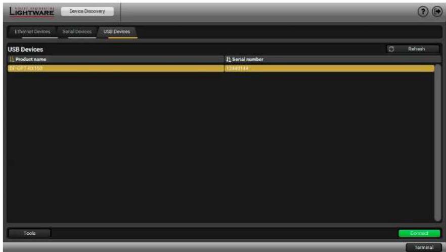
There are three tabs for the different type of interfaces: Ethernet, Serial, and USB. Select the USB tab to connect to the desired extender.
Establishing the Connection
Double click on the device or select it and click on the green Connect button. Please note that if you connect to the Transmitter directly, it must be in Configuration mode.
5.3. Control menu
The Control menu shows basic information about the extender(s) in three panels. The Connected text is displayed in the extender's title that is connected to the computer directly.
| Parameter State and Description | |
| Fiber link | Connected: Transmitter and Receiver are linkedDisconnected: no fiber connection |
| DP link speed and channels | According to the incoming signal (only in DP mode) |
| Video mode | DisplayPortHDMI: passive adaptor is connected to the receiver |
| Video source state | ON: source is present in DP modeNot connected: source is not connectedn/a: no information about the signal (HDMI mode) |
| Monitor state | ON: DP or HDMI displayOFF: display device is not connected |
| HDCP enable | checked: HDCP enabledunchecked: HDCP disabled |
5.3.1. Video and Link Panel
Basic information is displayed about the extenders and the video signal. If the extenders are linked by fiber cable, they can read information about each other and display.
INFO: Source can be forced to send unencrypted signal (if the content allows) by unchecking the HDCP enable setting.
INFO: HDCP enable setting can be changed in DP and HDMI mode also, but effects only when DVI/HDMI adaptor is connected. When HDCP is changed in DP mode, the setting is stored and will be applied when an adaptor is connected.
text_image
Lightware Device Discovery Ethernet Devices Serial Devices USB Devices USB Devices Product name Serial number DF-GPT RX150 12340144 Tools Connect TerminalThe Device Discovery Window


- Software Control - Lightware Device Controller Software DP-OPT-TX150, DP-OPT-RX150 - User's Manual 14
5.3.2. Transmitter Panel
Two channels are used for the USB communication, which can be set as described in the USB Modes section. Channel 1 is always transparent, Channel 2 can be set to transparent or configuration mode.
| Parameter State and Description | |
| USB host (computer) | Connected |
| USB Channel 1 mode Transparent (always) | |
| USB Channel 1 state | ActiveNot connected (it depends on the HID devices) |
| USB Channel 2 mode | ConfigurationTransparent |
| USB Channel 2 status | Active |
ATTENTION! USB Channel 2 mode can be changed by a drop-down menu. When switched to transparent mode, the extender is disconnected from the LDC immediately.

text_image
Lightware USB DP-OPT-RX150 12440144 Control Settings Fiber line: Connected DP Link speed: Unknown DP Link channels: Unknown Video mode: DisplayPort Video source state: Not connected Monitor state: Not connected HDCP mode: DP-OPT-TX150 USB host (Compute): Not connected USB Channel 1 mode: Transparent USB Channel 1 state: Not connected USB Channel 2 mode: Transparent USB Channel 2 state: Not connected DP-OPT-RX150 (Connected) Connected USB devices Manufacture Product Type Ch Status VID PID Add MOON AND HID Mouse A2 Active 13EE 0091 2 SEM USB Keyboard HID Keyboard A1 Active 1A2C 2124 104 Blocked USB devices ID Name VID PID Block selected Block manually TerminalThe Control Menu


- Software Control - Lightware Device Controller Software DP-OPT-TX150, DP-OPT-RX150 - User's Manual 15
5.3.3. Receiver Panel
The panel consists of the lists that are showing connected and blocked USB devices.
Connected USB Devices
The listed devices are connected to the receiver's USB ports.
| DP-OPT-RX150 (Connected) | |||||||
| Connected USB devices | |||||||
| Manufacturer | Product | Type | Ch | Status | VIB | PID | Addr |
| Kingston | - | Unknown | - | Not supported | D951 | 1665 | 1 |
| SEM | USB Keyboard | HD Keyboard | A1 | Active | T42C | 2124 | 2 |
Parameters
| Parameter State and Description | |
| Manufacturer, Product, Type As coded in the USB device. | |
| CH (Channel) | Channel A1 and A2 are used for USB communication. A1 is always transparent, A2 can be switched. The USB device on Channel A1 was connected to the receiver the earliest. |
| Status | Active: the device is ready to use in transparent mode.Supported: the device is supported, but not active (no channel is available for extension).Unsupported: the device is not USB HID (e.g. pen drive). |
| VID, PID | Vendor ID and Product ID as coded in the USB device. |
| Address See the following section. | |
The Address of the Device
Address of the device plugged in 📄 = 1 and the device plugged 📇 in = 2. Since USB HUB can be connected to the receiver, the addresses are determined as follows:
• Address of the USB HUB: 100 (not visible)
- Address of the USB device connected to the first port of the USB HUB: 104
| DP-OPT-RX150 (Connected) | |||||||
| Connected USB devices | |||||||
| Manufacturer | Product | Type | Ch | Status | VDD | PID | Add |
| MOON | AND | HD Mouse | A3 | Active | 13EE | 0001 | 2 |
| SBM | USB Keyboard | HD Keyboard | A1 | Active | 142C | 2124 | 104 |
Above example shows a mouse that is connected to the USB port (Ch A1, Addr 2). The other device is a keyboard, which is connected via an USB HUB – that is why its address is not 1 but 101. Since the extenders are in configuration mode, only one device can be used: the one on channel A1 (the mouse).
However USB HUBs are supported by the receiver, only two devices are active at the same time in transparent mode: the devices which are closest to the root address. If an active device is disconnected, the next valid device (that is the closest to the root) will be active.
INFO: Channel A1 and A2 are assigned to the devices automatically when a new device is connected.
Port Numbers
The port numbers of the USB HUB determines the priority of the devices. When more devices are connected to an USB HUB, the USB port number determines the priority of the connected devices: the lower number, the higher priority. This priority has an effect when the channels are assigned to the devices.
Blocked USB Devices
The USB blocking feature allows you to activate the desired devices when more than two USB HID devices are connected to the receiver (two channels are available for USB extension). A typical example is shown in the Example 3: Connecting three USB HID devices and a HUB section.
Blocking a Device
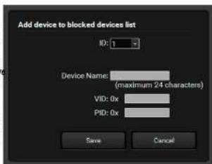
Step 1. Click on the Block manually button, or select a device from the Connected USB devices list and click on Block selected button.
Step 2. Check the fields in the appearing window (Device name, Vendor ID, Product ID) and click on Sava button. The ID is the number of the blocked device in the list.
Step 3. Click the Apply button in the bottom of the window to save changes. The desired device is added to the Blocked USB devices list and next time when you connect it to the receiver, its status will be displayed as Blocked.
Removing blocked devices
Step 1. Select the device from the Blocked USB devices list.
Step 2. Click on Remove button.
Step 3. Click on Apply button on the bottom of the screen to save changes.
INFO: The Remove all button will empty the list of blocked devices.
text_image
Add device to blocked devices list ID: 1 Device Name: (maximum 24 characters) VID: 0x PID: 0x Save Cancel


- Software Control - Lightware Device Controller Software DP-OPT-TX150, DP-OPT-RX150 - User's Manual 16
5.4. Real-life examples (USB devices and modes)
The background of the USB modes, connected USB devices, displayed information can be understood easier by presenting examples.
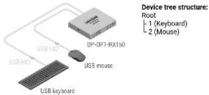
Example 1: Connecting Two USB HID Devices
flowchart
graph TD
    A["User"] --> B["USB keyboard"]
    B --> C["USB mouse"]
    C --> D["DP-3PT-RX150"]
    D --> E["User HD"]
    style A fill:#f9f,stroke:#333
    style B fill:#ccf,stroke:#333
    style C fill:#cfc,stroke:#333
    style D fill:#fcc,stroke:#333
    style E fill:#cff,stroke:#333
Shown in the LDC:
| DP-OPT-RX150 (Connected) | |||||||
| Connected USB devices | |||||||
| Manufacturer | Product | Type | Ch | Status | VID | PID | Adv |
| MOON | AND | HID Mouse | A2 | Active | 13EE | 0001 | 1 |
| SEM | USB Keyboard | HID Keyboard | A1 | Active | 1A2C | 2124 | 2 |
In a simple case a keyboard and a mouse are connected to the receiver.
In Transparent mode both devices are operable.
In Configuration mode only one of them is available (as seen on the screenshot), the keyboard on channel A1.
The second row (the mouse) is blinking, showing that the device is not available.
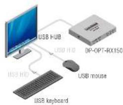
Example 2: Connecting Two USB HID Devices via an USB HUB
flowchart
graph TD
    A["USB HUB"] --> B["USB HD"]
    B --> C["USB mouse"]
    C --> D["DP-OPT-RX150"]
    E["USB keyboard"] --> F["Computer"]
Device tree structure:
Root
- 100 (USB HUB)
- 103 (Keyboard)
L 104 (Mouse)
Shown in LDC:

text_image
DP-OPT-RX150 (Connected) Connected USB devices Manufacturer Product Type Ch Status VID PID Add SEM USB Keyboard HID Keyboard A1 Active T2DC 2124 183 MOON AND HID Mouse A2 Active T3EE 0091 194This case is similar than the first, but now the mouse and the keyboard are connected to a local USB HUB. The HUB (with 4 available USB ports) is built into the monitor and connected to the receiver (the address of the HUB is 200). The keyboard is connected to the 2nd port (Addr. 202) and the mouse is connected to the 4th port of the HUB (Addr. 204).
In Transparent mode both devices are operable.
In Configuration mode only one USB HID device is available (as seen on the screenshot), the keyboard on channel A1. The second row (the mouse) is blinking, showing that the device is out of operation currently - due to the USB mode.
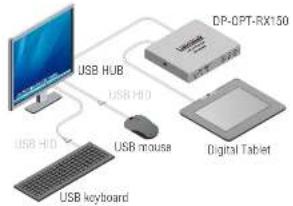
Example 3: Connecting three USB HID devices and a HUB
flowchart
graph TD
    A["USB HUB"] --> B["USB HUB"]
    A --> C["USB HUB"]
    A --> D["USB keyboard"]
    E["DP-CPT-RX150"] --> F["Digital Tablet"]
    G["USB mouse"] --> E
    G --> D
Device tree structure:
Root
2 (Digital Tablet)
100 (USB HUB)
103 (Keyboard)
104 (Mouse)
Shown in LDC:
| DP-OPT-RX150 (Connected) | |||||||
| Connected USB devices | |||||||
| Manufacturer | Product | Type | Ch | Ratio | VDD | FDD | Add |
| WACOM | CTE-648-U V4 | HID Mouse | A2 | Active | 056A | 0016 | 3 |
| SEM | USB Keyboard | HID Keyboard | A1 | Active | 142C | 2124 | 103 |
| MODON | AND | HID Mouse | Supported | 13EE | 0021 | 124 | |
On the third example three USB devices can be seen. A mouse and a keyboard are connected to the USB HUB that is connected to one of the receiver's USB port. A presenter device is connected to the other USB port (the presenter is listed as "Keyboard").
In Transparent mode two devices are operable: the presenter (on channel A1) and the keyboard (on channel A2). The presenter was connected to the receiver the earliest, that is why channel A1 is assigned to the presenter. The address number of the keyboard is lower than the mouse, that is why channel A2 is assigned to the keyboard. If you want to use the mouse, you have to block the presenter or the keyboard (the other option is to disconnect one of them).
In Configuration mode only one device is operable: the presenter on channel A1. Second row (the keyboard) is blinking, showing the device is not available – due to the USB mode.
INFO: Channel A1 and A2 are assigned to the devices automatically when a new device is connected; they cannot be changed manually.
INFO: The port numbers of the USB HUB determines the priority of the devices. When more devices are connected to an USB HUB, the USB port number determines the priority of the connected devices: the lower number, the higher priority. This priority has an effect when the channels are assigned to the devices.
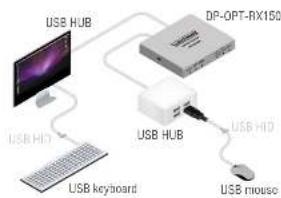
Example 4: Using an Apple LED cinema display
flowchart
graph TD
    A["USB HUB"] --> B["DP-OPT-RX150"]
    B --> C["USB HUB"]
    C --> D["USB HD"]
    D --> E["USB keyboard"]
    E --> F["USB mouse"]
Device tree structure:
Root
100 (USB HUB - built in the Display device)
101 (Mouse)
104
105
106
200 (USB HUB)
L 204 (Keyboard)
Shown in LDC:
| Connected USB devices | |||||||
| Manufacturer | Product | Type | Ch | Status | VID | PID | Addr |
| Logitech | - | Mouse | A1 | Active | 0460 | 095A | 101 |
| Apple Inc. | - | - | A2 | Active | 05AC | 1108 | 104 |
| Apple Inc. | - | - | Not supported | 05AC | 880B | 106 | |
| Apple Inc. | - | - | Supported | 03AC | 922B | 106 | |
| - | USB Keyboard | Keyboard | Supported | 0461 | 0010 | 204 | |
The last example shows a special layout, where an Apple LED cinema display (with built-in USB HUB), a mouse, a keyboard and another simple USB HUB are installed. The layout could cause headache, since the display contains three components which report themselves as HID devices. The result is that the keyboard's address is lower than the components in the display device and the keyboard will be operable neither in configuration, nor in transparent mode.
The solution in this case is to block the unnecessary devices, shown in the 2nd and 4th rows. (The device in the 3rd row is not supported, it is not necessary to block.) Block the two devices:
| DP-OPT-RX150Connected USB devices | |||||||
| Manufacturer | Product | Type | Ch | Status | VID | PID | Addr |
| Logitech | - | Mouse | A1 | Active | 0460 | COSA | 101 |
| Apple Inc. | - | - | Blocked | 05AC | 1105 | 104 | |
| Apple Inc. | - | - | Not supported | 05AC | 850B | 105 | |
| Apple Inc. | - | - | Blocked | 05AC | 9226 | 106 | |
| - | USB Keyboard | Keyboard | A2 | Active | 0461 | 0078 | 304 |
Thus in Transparent mode the mouse and the keyboard will be operable.
In Configuration mode only the mouse is available, that is why the last row is blinking.


- Software Control - Lightware Device Controller Software DP-OPT-TX150, DP-OPT-RX150 - User's Manual 18
5.5. Terminal Menu
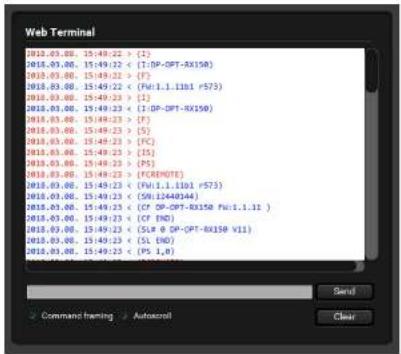
The general purpose of this serial terminal is intended mainly for testing and debugging purposes. Nevertheless, when the window is open, the automatically executed commands can be followed on the screen.
text_image
Web Terminal 2018.03.00 15:49:22 > (S) 2018.03.00 15:49:22 < (I:DP-DPT-RX150) 2018.03.00 15:49:22 > (F) 2018.03.00 15:49:22 < (Fu1.1.11b1 r573) 2018.03.00 15:49:23 > (S) 2018.03.00 15:49:23 < (I:DP-DPT-RX150) 2018.03.00 15:49:23 > (F) 2018.03.00 15:49:23 > (S) 2018.03.00 15:49:23 < (PCC) 2018.03.00 15:49:23 > (S) 2018.03.00 15:49:23 < (PDENOTE) 2018.03.00 15:49:23 < (Fu1.1.11b1 r573) 2018.03.00 15:49:23 < (SUI444D44) 2018.03.00 15:49:23 < (CF DP-DPT-RX150 Fu1.1.11 ) 2018.03.00 15:49:23 < (CF END) 2018.03.00 15:49:23 < (SLR @ DP-DPT-RX150 V11) 2018.03.00 15:49:23 < (SL END) 2018.03.00 15:49:23 < (PS 1,6) Send Command training Autoconnal ClearTerminal Window
5.6. Settings menu
5.6.1. Device information
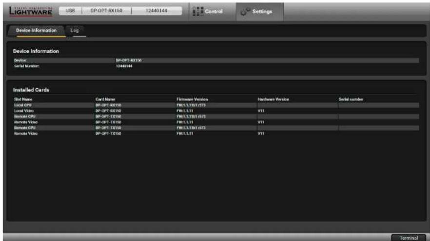
Basic information about the extender, such as type, serial number, firmware and hardware revisions are displayed on this tab.
text_image
LightWARE USB DP-OPT 40X150 12440144 Control Settings Device Information Log Device Information Device: DP-OPT-RX150 Serial Number: 12440144 Installed Cards Spot Name Card Name Firmware Version Hardware Version Serial number Local GPU DP-OPT-RX150 FW1.1.336/4275 Local Videos DP-OPT-RX150 FW1.1.11 V11 Remote GPU DP-OPT-RX150 FW1.1.138/4275 Remote Videos DP-OPT-TX150 FW1.1.11 V11 Remote GPU DP-OPT-RX150 FW1.1.138/4275 Remote Videos DP-OPT-TX150 FW1.1.11 V11 TerminalThe Device Information Tab


- Software Control - Lightware Device Controller Software DP-OPT-TX150, DP-OPT-RX150 - User's Manual 19
5.6.2. Log Tab
Generate Report
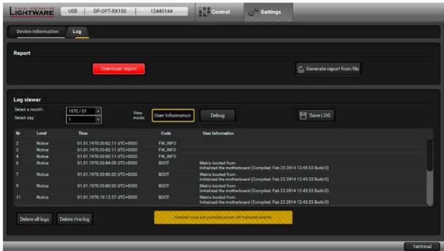
LDC is able to collect information from the extender and save it to a report file. This information package can be sent to Lightware support team when a problem may arise with the extender.
ATTENTION! When a report is necessary to generate, always let devices (source, sink) be connected to the extenders, do not disconnect them. Lightware Device Controller will collect information about the USB devices and about their status.
Step 1. Press the big red Download report labeled button on the Log tab in Settings menu.
Step 2. LDC collects the needed information in a minute.
Step 3. When the process is finished, the Save as dialog box appears. Select the place where you want to save the report file. The default file name can be changed.
The report contains the following information:
- Current command protocol
• The equipment type and serial number - Firmware version of the controller
• Installed I/O board type and version
Generating a Custom Report File
INFO: This function is only for special troubleshooting cases.
Device Controller is able to send a custom command file to the extender. The command file can be generated by Lightware support. This is needed when some special commands has to be used for configuring or troubleshooting.
text_image
LightWARE USB DP-DPT-RX150 12440144 Control Settings Device Information Log Report Download report Generate report from file Log viewer Select a month: 1970/01 Select day: 1 View mode User Information Debug Save LOG No Level Time Code User Information 2 Notice 01.01.1970.00.02.11 UTC+0000 FW_INFO 3 Notice 01.01.1970.00.02.11 UTC+0000 FW_INFO 4 Notice 01.01.1970.00.02.11 UTC+0000 FW_INFO 5 Notice 01.01.1970.00.04.08 UTC+0000 BOOT Matrix booted from Initiated the motherboard (Completed: Feb 25 2014 12:45:53 Build:0) 7 Notice 01.01.1970.00.00.00 UTC-0000 BOOT Matrix booted from Initiated the motherboard (Completed: Feb 25 2014 12:45:53 Build:0) 9 Notice 01.01.1970.00.00.00 UTC+0000 BOOT Matrix booted from Initiated the motherboard (Completed: Feb 25 2014 12:45:53 Build:0) 11 Notice 01.01.1970.18.13.97 UTC+0000 BOOT Matrix booted from Initiated the motherboard (Completed: Feb 25 2014 12:45:53 Build:0) Delete all logs Delete this log Invalid results are possible power off handwrist events TerminalThe Log Tab

Firmware Upgrade
The extenders can be upgraded by using Lightware Device Updater (LDU) software via the USB port. The application and the User's manual can be downloaded from www.lightware.com. In order to get the firmware pack with the necessary components (*.lfp file) for your specific product, please contact support@lightware.com.
▶ ABOUT THE FIRMWARE PACKAGE (LFP FILE)
SHORT INSTRUCTIONS
INSTALL AND UPGRADE
▶ DETAILED INSTRUCTIONS
ATTENTION! While the firmware is being upgraded, the normal operation mode is suspended as the receiver is switched to bootloader mode. Signal processing is not performed. Do not interrupt the firmware upgrade. If any problem occurs, reboot the receiver and restart the process.
6.1. About the Firmware Package (LFP File)
The firmware files are packed in an LFP package. You need only this file to do the upgrade on your device.
- The package contains all the necessary components, binary, and other files; You do not have to get further files.
- There is a descriptor file in the package that contains each firmware with version number and a list showing the compatible devices. The descriptor is displayed after loaded the LFP file in the LDU.
6.2. Short Instructions
Step 1. Get the firmware pack and the Lightware Device Updater (LDU) application.
Step 2. Install the LDU application.
Step 3. Establish the connection between the computer and the device(s).
Step 4. Start the LDU and follow the instructions shown on the screen.
6.3. Install and Upgrade
Installation for Windows OS
INFO: The application can be installed under Windows XP or above. Run the installer. If the User Account Control drops a pop-up message click Yes. During the installation you will be prompted to select the type of the installation:
| Normal install Snapshot Install | |
| Available for Windows and Mac OS X Available for Windows | |
| The installer can update only this instance Cannot be updated | |
| Only one updatable instance can existfor all users | More than one different versioncan be installed for all users |
Comparison of install types
ATTENTION! Using the Normal install as the default value is highly recommended.
Installation for Mac OS X
INFO After the installation the Windows and the Mac application has the same look and functionality. This type of the installer is equal with the Normal install in case of Windows and results an updatable version with the same attributes.
Mount the DMG file with double clicking on it and drag the LDU icon over the Applications icon to copy the program into the Applications folder. If you want to copy the LDU into another location just drag the icon over the desired folder.
LDU Upgrade
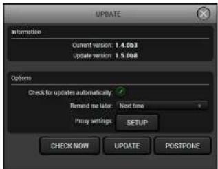
Step 1. Run the application. In the welcome screen click on the button in the top right corner, the About window will appear. Click on the Check now button. The program checks the available updates on Lightware website and shows its version.
text_image
UPDATE Information Current version: 1.4.0b3 Update version: 1.5.0b8 Options Check for updates automatically. Remind me later: Next time Proxy settings: SETUP CHECK NOW UPDATE POSTPONEStep 2. Set the desired update settings in the Options section.
- If you do not want to check for the updates automatically, uncheck the circle, which contains the green tick.
- If you want to postpone the update, a reminder can be set with different delays from the drop down list.
- If the proxy settings traverse the update process, set the proper values then click the OK button.
Step 3. Press the Update button to download the new version; the installer will start.


- Firmware Upgrade DP-OPT-TX150, DP-OPT-RX150 - User's Manual 21
6.4. Detailed Instructions
6.4.1. Establish the Connection
Make sure that the computer and the device are connected via USB. If you connect Transmitter, it must be in Configuration mode.
6.4.2. Start the LDU and Follow the Instructions
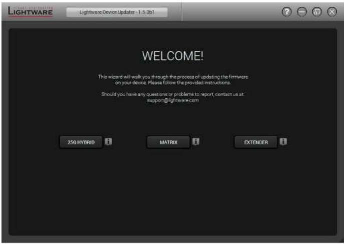
After launching LDU the welcome screen will appear. Pressing the button a list will appear showing the supported devices. Click on the Extender button on the main screen.
text_image
LIGHTWARE Lightware Device Updates - 1.5.3b3 WELCOME! This wizard will walk you through the process of updating the firmware on your device. Please follow the provided instructions. Should you have any questions or problems to report, contact us at: support@lightware.com 25G HYBRID MATRIX EXTENDERStep 1. Select the Package.
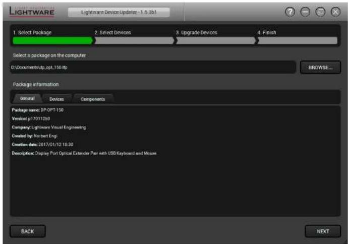
Click on the Browse button and select the *.Ifp* file that will be used for the upgrade.
Package information is displayed:
- General version info, creation date, short description,
• Devices which are compatible with the firmware, - Components in the package with release notes.
Click on the Next button and follow the instructions.
text_image
LIGHTWARE Lightware Device Updates - 1.0.3b1 1. Select Package 2. Select Devices 3. Upgrade Devices 4. Finish Select a package on the computer D:\Documents\dp.asp.150.fbp BROWSE... Package information General Devices Components Package name: DP-OPT-150 Version: p17011268 Company: Lightweight Visual Engineering Created by: Norbert Engi Creation date: 2017/01/12 18:30 Description: Display Port Optical Extender Pair with USB Keyboard and Mouse BACK NEXTTIPS AND TRICKS: Files with ".Ifp" extension are associated to LDU during installation. If you double click on the ".Ifp" file, the application is launched, the package is loaded automatically and above screen is shown.


- Firmware Upgrade DP-OPT-TX150, DP-OPT-RX150 - User's Manual 22
Step 2. Select the Device.
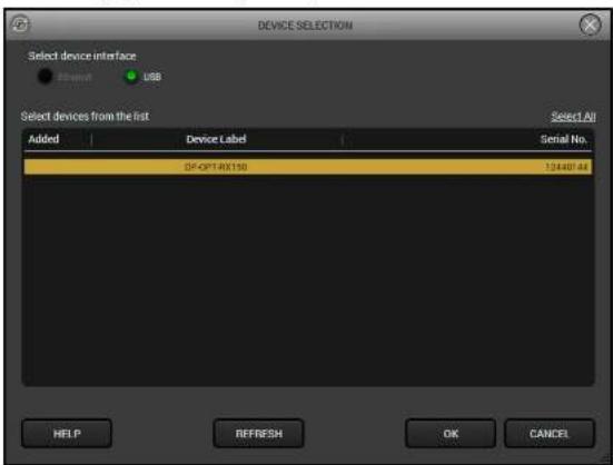
The following step is to select the desired device(s). The available and supported devices are searched and listed automatically. If the desired device is not listed, update the list by clicking the Refresh button. Select the desired devices: highlight them with a yellow cursor, then click OK.
text_image
DEVICE SELECTION Select device interface ShowA USB Select devices from the list Added Device Label Serial No. DF-OPT4X150 124407.48 HELP REFRESH OK CANCEL Select AllA tick mark can be seen in the Added column if the device was added by the user previously.
Firmware Components
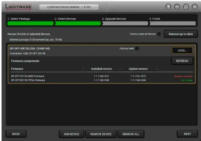
The firmware components of the selected devices are listed on the following screen: installed and update versions. (Update version will be uploaded to the device.)
text_image
LIGHTWARE Lightware Device Update - 1.3.251 1. Select Package 2. Select Devices 3. Upgrade Devices 4. Finish Review the list of selected devices Factory reset all devices Remove up-to-date Selected package D:\Documents\dp.opt_150.fp DP-OPT-RX150 (SN: 12440144) Connection: USB, DP-OPT-RX150 Factory reset LESS... Firmware components Firmware Installed version Update version DP-OPT-TX150 APM Firmware 1.1.1180 /551 1.1.1181 /573 DP-OPT-RX150 FPGA Firmware 1.1.1180 /546 1.1.1180 /546 Refresh Update available Up to turn BACK ADD DEVICE REMOVE DEVICE REMOVE ALL NEXTAdd a device by clicking on the Add device button. The previous screen will be shown; select the desired device(s) and click on OK. Remove a device by selecting it (highlight with yellow) and click on Remove device button, or click on Remove all button to empty the list.
Enabling Factory reset will perform factory default values for all settings in the device. The following cases may appear:
- Enabled by user: all settings will set to factory default values.
- Disabled by user: your settings will be saved and restored after upgrading.
- Enabled by default and not changeable by user: firmware upgrade must perform a factory reset to apply all changes coming with the new firmware version.
Click on the Next button to continue.


- Firmware Upgrade DP-OPT-TX150, DP-OPT-RX150 - User's Manual 23
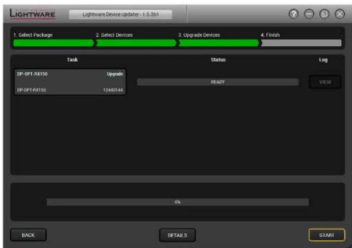
Step 3. Upgrade the device.
Click on the Start button to continue.
text_image
LIGHTWARE Lightware Device Updater - 1.5.3b1 1. Select Package 2. Select Devices 3. Upgrade Devices 4. Finish Task Status Log DP-OPT-RX150 Upgrade READY VIEW DP-OPT-RX150 12440144 0% BACK DETAILS STARTA window will pop up before starting upgrading the device; confirm by the OK button or Cancel to stop the process.
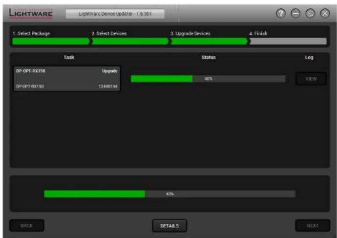
When you confirmed the upgrade process is started.
text_image
LIGHTWARE Lightware Device Updater - 1.5.3b1 1. Select Package 2. Select Devices 3. Upgrade Devices 4. Finish Task Status Log DP-OPT-RX150 Upgrade DP-OPT-RX150 12440146 40% VIEW 40% BACK DETAILS MLX1Details button opens a new window where the process is logged.


- Firmware Upgrade DP-OPT-TX150, DP-OPT-RX150 - User's Manual 24
Step 4. Finish.
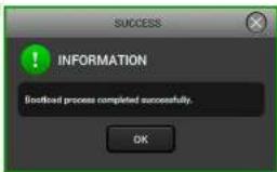
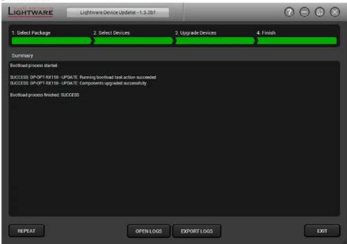
If the upgrade of a device is finished, the log can be opened by the View button on the right When all the tasks are finished, a window appears. Click OK to close and Next to display the summary page.
Repeat button starts the process again with the selected device(s). Open logs button opens the temporary folder where the logs can be found. Export logs by saving the files as a zipped file.
text_image
INFORMATION Bootflood process completed successfully. OKPress Exit to close the program.
If the upgrade failed, the progress bar of the device is changed to red; restart the devices and repeat the process.
ATTENTION! However the device is rebooted after the firmware upgrade, switching it off and on again is recommended.
text_image
LIGHTWARE Lightware Device Updater - 1.5.3b1 1. Select Package 2. Select Devices 3. Upgrade Devices 4. Finish Summary Bootload process started. SUCCESS DP-OPT-RX150 -UPDATE: Running bootload task action succeeded SUCCESS DP-OPT-RX150 -UPDATE: Components upgraded successfully Bootload process finished: SUCCESS REPEAT OPEN LOGS EXPORT LOGS EXIT7
Troubleshooting
Usually, if the system seems not to transport the signal as expected, the best strategy for troubleshooting is to check signal integrity through the whole signal chain starting from source side and moving forward to receiver end.
| Symptom Root cause Action | ||
| General video signal problems | ||
| Picture is not displayed or distorted | Video connectors are loose Make sure the connectors fit well. | |
| Another port is selected in the source/display device | Select the desired/connected port. | |
| When adaptor cable is applied: the source port does not support the Dual-mode | Extend the picture to a DisplayPort capable display device. | |
| The monitor is not able to display the desired image resolution | Select another display device or reduce the image resolution. | |
| Protected image is extended to a non-HDCP capable device | If the monitor does not support displaying HDCP-encrypted image content try to disable the HDCP (if the content allows). | |
| The fiber optical connector is not plugged or dirty | Check and clean the connectors carefully if necessary. | |
| Audio problems | ||
| No audio is present Not the right interface is selected in the source device | If the source is a computer make sure the audio is embedded in the video stream and not switched to an analog output. | |
| USB problems | ||
| Extended USB device does not work | The desired device is not connected | Check the cable connections; pay attention to the USB HUB if it was installed. |
| The Transmitter is in Configuration mode | In this case only one USB HID device is transmitted. Switch the Transmitter to Transparent mode if possible. | |
| Not supported USB device is connected | Only USB HID devices can be extended from the Transmitter to the Receiver. Check if it is supported. | |
| The USB device is not supported by the source computer | Check the device by plugging in the computer directly. | |
| Local USB device does not work | The USB device is not supported by the source computer | Check the device by plugging in the computer directly. |
8
Technologies
The following sections contain descriptions and useful technical information how the devices work in the background. The content is based on experiences and cases we met in the practice. These sections help to understand features and technical standards like the followings:
HDCP MANAGEMENT
DISPLAYPORT
8.1. HDCP Management
Lightware Visual Engineering is a legal HDCP adopter. Several functions have been developed which helps to solve HDCP related problems. Complex AV systems often have both HDCP and non-HDCP components. The devices allow transmitting HDCP encrypted and unencrypted signals. The devices will be still HDCP compliant as they will never output an encrypted signal to a non-HDCP compliant display device. If an encrypted signal is switched to a non-compliant output, a red screen alert or muted screen will appear.
8.1.1. Protected and Unprotected Content
Many video sources send HDCP protected signal if they detect that the sink is HDCP capable – even if the content is not copyrighted. This can cause trouble if an HDCP capable device is connected between the source and the display. In this case, the content cannot be viewed on non-HDCP capable displays and interfaces like event controllers. Rental and staging technicians often complain about certain laptops, which are always sending HDCP encrypted signals if the receiver device (display, matrix router, etc.) reports HDCP compliancy. However, HDCP encryption is not required all the time e.g. computer desktop image, certain laptops still do that.
To avoid unnecessary HDCP encryption, Lightware introduced the HDCP enabling/disabling function: the HDCP capability can be disabled in the Lightware device. If HDCP is disabled, the connected source will detect that the sink is not HDCP capable, and turn off authentication.
8.1.2. Real-life Examples
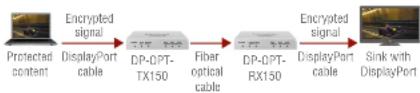
Sink with DisplayPort
All the devices are HDCP-compliant, no manual setting is required, both protected and unprotected content is transmitted and displayed on the sink.
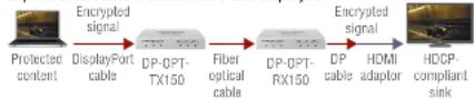
HDCP-compliant Sink (HDMI/DVI)
The display device is connected to the receiver through a passive DVI/HDMI adaptor. The sink is HDCP-compliant, so the situation is similar then in first case: no manual setting is required, both protected and unprotected content transmitted and displayed.
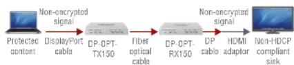
Non-HDCP Compliant Sink (HDMI/DVI) 1.
The non-HDCP compliant display device is connected to the receiver through a passive DVI/HDMI adaptor. Some sources (e.g. computers) always send HDCP encrypted signals if the receiver device reports HDCP compliancy, however HDCP encryption is not required all the time (e.g. computer desktop image). If the HDCP is enabled in the extenders, the image will not be displayed.
flowchart
graph LR
    A["Protected content"] -->|Non-encrypted signal| B["DisplayPort cable"]
    B --> C["DP-OPT-TX150"]
    C --> D["Fiber optical cable"]
    D --> E["DP-OPT-RX150"]
    E --> F["Non-encrypted signal"]
    F --> G["DP cable"]
    F --> H["HDMI adaptor"]
    G --> I["Non-HD/DC compliant sink"]
On DP-OPT extenders 'HDCP enable' function can be disabled (HDCP LED is dark), thus the source can be forced to send non-encrypted signal. Since the image content is unprotected, the source will send the signal and the sink will display the image.
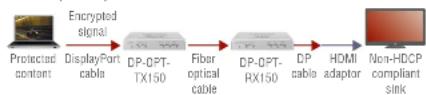
Non-HDCP Compliant Sink (HDMI/DVI) 2.
The layout is the same as in previous case: non-HDCP compliant display device is connected to the receiver. Now the difference is that the content is protected, thus the source is sending encrypted signal. In this case the source does not send any signal because it detects non-compliant system.
flowchart
graph LR
    A["Protected content"] -->|Encrypted signal| B["Display/Port cable"]
    B --> C["DP-OPT-TX150"]
    C --> D["Fiber optical cable"]
    D --> E["DP-OPT-RX150"]
    E --> F["DP cable"]
    F --> G["HDMI adaptor"]
    G --> H["Non-HDCP compliant sink"]
The display device will show muted screen or pop up an error message that the sink is not HDCP-compliant. The solution is to replace the display device to a HDCP-capable one.


- Technologies DP-OPT-TX150, DP-OPT-RX150 - User's Manual 27
8.2. DisplayPort
DisplayPort is a widely spread audio/video interface standard designed by VESA (Video Electronics Standard Association) in 2006. The aim was to create such an interface that would be the connection between graphic cards and display devices. The standard is available and free thus it can be implemented widely, which could help replacing the previously used interfaces, such as VGA or DVI.
Lightware's DP-OPT extenders are designed according to DisplayPort standard 1.1a. The maximum allowed bandwidth is 10.8 Gbps, which means e.g. 2560x1600 pixel resolution at 60 Hz or 4096x2400 pixels at 30 Hz. Color depth until 16 bits per color and 8-channel embedded LPCM audio is supported.
8.2.1. Dual Mode
Mentioned standard was designed to support HDMI/DVI display devices too. If the sink is assembled with DVI or HDMI input connector, it can be connected to a dual mode DisplayPort source by a passive adaptor (DP++) In this case, source switches to DVI/HDMI mode and the signal is changed to be in line with DVI/HDMI requirements.
INFO: Most of the sources assembled with DisplayPort supports Dual mode, but if you are not sure check the documentation of your device.
Passive adaptor
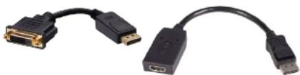
Display device with HDMI or DVI connector can be connected by a passive DP-HDMI or DP-DVI adaptor to the source. The passive adaptor has two functions: sending a sign to the source if DVI or HDMI signal is required, and doing level shifting from +3.3V to +5V. The source switches to DVI/HDMI mode and sends the proper signal.
natural_image
Two black USB connectors with gold connector, shown side by side (no text or symbols visible)DP-DVI and DP-HDMI Passive Adaptors
INFO: More information about adaptors can be found in VESA DisplayPort Interoperability Guideline (www.displayport.org).

Appendix
SPECIFICATIONS
MECHANICAL DRAWINGS
▶ FURTHER INFORMATION
9.1. Specifications
General
Compliance CE
EMI/EMC EN 55035:2017, EN 55032:2015
Safety EN 60065:2014, Class II
Warranty 3 years
Operating temperature 0°C \~ +55°C
Humidity 10 \~ 90% RH
Power source 100-240 V AC; 50\~60 Hz
Power
Power supply....External power adaptor
Power adaptor.....Input 100-240V AC 50/60Hz, Output 5V DC, 2A
Power consumption (TX150) 2.75W (typ)
3W (max., without USB extension)
3.1W (typ, with USB extension)
.8.2W (max., with 2x500mA for local USB devices)
Power consumption (RX150) 3.25W (typ)
3.5W (max., without USB extension)
3.75W (typ., with USB extension)
Enclosure
Material......Solid aluminum body
Dimensions (mm) W110 x D95 x H18
Dimensions (inch).....W4.3 x D3.7 x H0.7
Net weight 300g / unit
Connectors / ESD protection (HBM EIA/JESD22-A114F)
Video in / out......Standard DisplayPort 20-pole connector / 8 kV
Optical fiber in/out.....SC receptacle / 8 kV
USB port for devices....USB-A receptacle / 4 kV
USB port for control....USB Mini-B receptacle / 4 kV
Power connector.....DC connector (1.35 mm pin) / 2 kV
Digital video signal
Standard ...... DisplayPort 1.1a (Dual-mode)
Color depth....24, 30, 36, 48 bits deep color
Date rates .... 1.62 / 2.7 Gbps (1.65 Gbps /lane), max. 10.8 Gbps total
Video delay 0 frame
Max resolution at 60 Hz 2560x1600 pixels
Max resolution at 30 Hz ....4Kx2K, 4096x2400 pixels
Max resolution at 120 Hz....1920x1080 pixels, 24 bit
HDCP pass through .... Supported
Optical
Fiber type....50/125 SC Multimode (preferred)
62.5/125 SC Multimode
Laser wavelengths....High speed lanes: 778; 800; 825; 850 nm
Low speed lanes: 911; 980 nm
Laser class specification.... Class 3R
Transmitter output OMA* -6.25 dBm (worst case)
Receiver OMA* sensitivity....-14.25 dBm (worst case)
Transmission distance ..... 1100 meters (using OM4 50/125 fiber)
800 meters (using OM3 50/125 fiber)
350 meters (using OM2 50/125 fiber)
150 meters (using OM1 62.5/125 fiber)
*OMA: Optical Modulation Amplitude
USB support
USB control (TX150: labelled 'CPU')....USB 2.0
USB control (RX150: labelled 'Service')....USB 2.0
Local USB ports (TX150)....USB 2.0 HiSpeed 480 Mbps
Extended USB ports (RX150)....USB HID


- Appendix DP-OPT-TX150, DP-OPT-RX150 - User's Manual 29
9.2. Mechanical Drawings
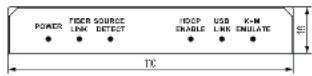
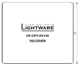
The dimensions are in mm.
Front View Rear View

Top View
text_image
visual engineering LIGHTWARE DP-OPT-RX150 RECEIVERBottom View
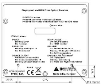
text_image
Displayport and USB Fiber Optical Receiver FUNCTIONS: Series Press for 2 seconds to charge USB ports Press for 10 seconds to control the USB/USB in HDMI mode FUNCTION LCD Installation POWER Gaussor: Dinar Dr. Power Power Input: Marking: Wavelength 15 Dr. TC Conducted Source: RESET USB to source connected Dr. State connected to 16 Mening: Unknown (Microbus) Power INPUT 5V DC, USA Risks Radio Radio Input Radio In U.S. Hungary HOLDungsable HD-USB - disabled Dr. HUSB rated USB I/OCK Dr. Minimumed to 18 Marking: Wavelength 1500 microbus Dr. Aird connection Anchrolate VAS model OM Transmitter OM Transmitter Dr. State and keyboard Linked 2125 575 6.3 MB SignalLeft Side View


- Appendix DP-OPT-TX150, DP-OPT-RX150 - User's Manual 30
9.3. Further Information
Limited Warranty Statement
- Lightware Visual Engineering LLC (Lightware) warrants to all trade and end user customers that any Lightware product purchased will be free from manufacturing defects in both material and workmanship for three (3) years from purchase unless stated otherwise below. The warranty period will begin on the latest possible date where proof of purchase/delivery can be provided by the customer. In the event that no proof can be provided (empty 'Date of purchase' field or a copy of invoice), the warranty period will begin from the point of delivery from Lightware.
1.1. 25G and MODEX product series will be subject to a seven (7) year warranty period under the same terms as outlined in this document.
1.2. If during the first three (3) months of purchase, the customer is unhappy with any aspect of a Lightware product, Lightware will accept a return for full credit.
1.3. Any product that fails in the first six (6) months of the warranty period will automatically be eligible for replacement and advanced replacement where available. Any replacements provided will be warranted for the remainder of the original unit's warranty period.
1.4. Product failures from six (6) months to the end of the warranty period will either be repaired or replaced at the discretion of Lightware. If Lightware chooses to replace the product then the replacement will be warranted for the remainder of the original unit's warranty period.
- The above-stated warranty and procedures will not apply to any product that has been:
2.1. Modified, repaired or altered by anyone other than a certified Lightware engineer unless expressly agreed beforehand.
2.2. Used in any application other than that for which it was intended.
2.3. Subjected to any mechanical or electrical abuse or accidental damage.
2.4. Any costs incurred for repair/replacement of goods that fall into the above categories (2.1., 2.2., 2.3.) will be borne by the customer at a pre-agreed figure.
- All products to be returned to Lightware require a return material authorization number (RMA) prior to shipment and this number must be clearly marked on the box. If an RMA number is not obtained or is not clearly marked on the box, Lightware will refuse the shipment.
3.1. The customer will be responsible for in-bound and Lightware will be responsible for out-bound shipping costs.
3.2. Newly repaired or replaced products will be warranted to the end of the originally purchased products warranty period.
Document Revision History
| Rev. | Release date | Changes Editor | |
| 1.0 | 01-10-2013 Initial version | Laszlo Zsedenyi | |
| 1.1 | 25-11-2014 | Firmware upgrade process, Lightware Device Updater and Lightware Device Controller added | Laszlo Zsedenyi |
| 1.2 | 19-02-2015 | DisplayPort connector pin assignments corrected | Laszlo Zsedenyi |
| 1.3 | 15-12-2015 | Safety instructions updated, CE page pulled out | Laszlo Zsedenyi |
| 1.4 | 06-10-2016 | Minor updates to the latest LDC and LDU software, updated warranty info | Tamas Forgacs |
| 2.0 | 13-03-2018 | New document format introduced; latest SW and FW editions added. | Laszlo Zsedenyi |
| 2.1 | 30-10-2018 | 108p120 Hz signal support info added. | Laszlo Zsedenyi |
Contact Us
sales@lightware.com
+36 1 255 3800
support@lightware.com
+36 1 255 3810
Lightware Visual Engineering LLC.
Peterdy 15, Budapest H-1071, Hungary
www.lightware.com
©2018 Lightware Visual Engineering. All rights reserved. All trademarks mentioned are the property of their respective owners. Specifications subject to change without notice.