DVIDL-OPT-TX200 - Audio/video extender Lightware - Free user manual and instructions
Find the device manual for free DVIDL-OPT-TX200 Lightware in PDF.


| Product Type | Dual-Link DVI Optical Transmitter (Extender) |
| Brand | Lightware |
| Model | DVIDL-OPT-TX200 |
| Dimensions (W x D x H) | 110 mm x 181 mm x 42.2 mm (excluding connectors) |
| Weight | 726 g (1.601 lbs) |
| Power Supply | External adaptor: 100-240 V AC 50/60 Hz, output 5 V DC, 2.5 A |
| Power Consumption | 3.5 W (self-consumption, without remote powering) |
| Video Input | 1x DVI-I (digital only), dual-link capable |
| Video Outputs | 1x DVI-I local monitor output; 1x Neutrik opticalCON LC duplex fiber output |
| Maximum Resolution | 4096x2400 (dual-link) up to 330 MHz pixel clock |
| Fiber Connector | Neutrik NO2-4FDW type LC duplex; supports LC connectors |
| Fiber Type | Multimode 50/125 µm |
| Maximum Transmission Distance | 2500 m (with OM3e fiber for 1080p@60Hz 24bpp) |
| EDID Management | Advanced: 60 factory preset EDIDs, 39 user-programmable slots; front panel rotary switches and LEARN button |
| Front Panel LEDs | Source +5V, Monitor Hotplug, Signal Present, Laser Active, EDID Status, Power |
| Control Interface | USB mini-B for Lightware Device Controller (LDC) software and firmware upgrade |
| Operating Temperature | 0 to +50 °C (+32 to +122 °F) |
| Compliance | CE, EN 55032 (Emission), EN 55035 (Immunity), EN 60065 Class II safety |
| Cooling | Passive (no fans) |
| Mounting | Quarter-rack size; optional 1U rack shelf for multiple units |
| Cleaning and Maintenance | Clean exterior with dry cloth; no user-serviceable parts inside |
| Safety Precautions | Class II apparatus; do not remove cover; laser product (Class 3R) – avoid direct exposure; indoor use only |
| Spare Parts and Repairability | Contact Lightware support for repairs; no user-serviceable components |
Frequently Asked Questions - DVIDL-OPT-TX200 Lightware
User questions about DVIDL-OPT-TX200 Lightware
0 question about this device. Answer the ones you know or ask your own.
Ask a new question about this device
Download the instructions for your Audio/video extender in PDF format for free! Find your manual DVIDL-OPT-TX200 - Lightware and take your electronic device back in hand. On this page are published all the documents necessary for the use of your device. DVIDL-OPT-TX200 by Lightware.
USER MANUAL DVIDL-OPT-TX200 Lightware
Important Safety Instructions
Class II apparatus construction.
The equipment should be operated only from the power source indicated on the product.
To disconnect the equipment safely from power, remove the power cord from the rear of the equipment, or from the power source. The MAINS plug is used as the disconnect device, the disconnect device shall remain readily operable.
There are no user-serviceable parts inside of the unit. Removal of the cover will expose dangerous voltages. To avoid personal injury, do not remove the cover. Do not operate the unit without the cover installed.
The appliance must be safely connected to multimedia systems. Follow instructions described in this manual.
Ventilation
For the correct ventilation and to avoid overheating ensure enough free space around the appliance. Do not cover the appliance, let the ventilation holes free and never block or bypass the ventilators (if any).
WARNING
To prevent injury, the apparatus is recommended to securely attach to the floor/wall or mount in accordance with the installation instructions. The apparatus shall not be exposed to dripping or splashing and that no objects filled with liquids, such as vases, shall be placed on the apparatus. No naked flame sources, such as lighted candles, should be placed on the apparatus.
Waste Electrical & Electronic Equipment WEEE
This marking shown on the product or its literature, indicates that it should not be disposed with other household wastes at the end of its working life. To prevent possible harm to the environment or human health from uncontrolled waste disposal, please separate this from other types of wastes and recycle it responsibly to promote the sustainable reuse of material resources. Household users should contact either the retailer where they purchased this product, or their local government office, for details of where and how they can take this item for environmentally safe recycling. Business users should contact their supplier and check the terms and conditions of the purchase contract. This product should not be mixed with other commercial wastes for disposal.
Caution: Laser product

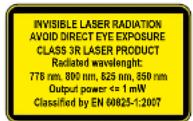
Common Safety Symbols

| Symbol Description | |
| --- | Direct current |
| Alternating current | |
| Double insulation | |
| Caution, possibility of eletric shock | |
| Caution | |
| Laser radiation | |
| Caution: for indoor use only | |


DVIDL-OPT series - User's Manual 3
Symbol Legend
The following symbols and markings are used in the document:
WARNING! Safety-related information which is highly recommended to read and keep in every case!
ATTENTION! Useful information to perform a successful procedure; it is recommended to read.
INFO: A notice which may contain additional information. Procedure can be successful without reading it.
DEFINITION: The short description of a feature or a function.
TIPS AND TRICKS: Ideas which you may have not known yet but can be useful.
Navigation Buttons
Go back to the previous page. If you clicked on a link previously, you can go back to the source page by clicking the button.
Navigate to the Table of Contents.
Step back one page.
Step forward to the next page.
Document Information
All presented functions refer to the indicated products. The descriptions have been made during testing these functions in accordance with the indicated Hardware/Firmware/Software environment:
| Item Version | |
| Lightware Device Controller (LDC) software 1.24.0 | |
| Lightware Bootloader software 3.3.3 | |
| Controller firmware - DVIDL-OPT-TX200 1.2.3 | |
| Controller firmware - DVIDL-OPT-RX100 1.2.2 | |
| Hardware - DVIDL-OPT-TX200 1.1 | |
| Hardware - DVIDL-OPT-RX100 1.0 |
Document revision: 3.0
Release date: 30.08.2018
Editor: Laszlo Zsedenyi
About Printing
Lightware Visual Engineering supports green technologies and Eco-friend mentality. Thus, this document is made for digital usage primarily. If you need to print out few pages for any reason, follow the recommended printing settings:
• Page size: A4
• Output size: Fit to page or Match page size
- Orientation: Landscape
TIPS AND TRICKS: Thanks to the size of the original page, a border around the content (gray on the second picture below) makes possible to organize the pages better. After punching the printed pages, they can be placed easily into a ring folder.
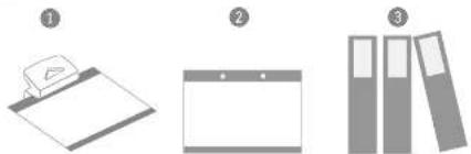
natural_image
Three grayscale illustrations of office supplies: a clipboard, a blank tablet, and stacked folders (no text or symbols)Table of Contents
- INTRODUCTION 5
1.1.DESCRIPTION ....5
1.2. BOX CONTENTS .... 5 1.3. COMPATIBLE DEVICES .... 5
1.3. COMPATIBLE DEVICES ....5 1.4. FEATURES OF THE EXTENDERS ....6
1.4 FEATURES OF THE EXTENDERS 6 1.5. TYPICAL APPLICATIONS 6
1.01.11.12.13.14.15.16.17.18.19.20.21.22.23.24.25.26.27.28.29.30.31.32.33.34.35.36.37.38.39.40.41.42.43.44.45.46.47.48.49.50.51.52.53.54.55.56.57.58.59.60.61.62.63.64.65.66.67.68.69.70.71.72.73.74.75.76.77.78.79.80.81.82.83.84.85.86.87.88.89.90.91.92.93.94.95.96.97.98.99.100 - INSTALLATION....7
2.1. RACK SHELF MOUNTING....7
2.2. CONNECTING STEPS.... - PRODUCT OVERVIEW 8
3.1. FRONT VIEW (TRANSMITTER)......8
3.2. REAR VIEW (TRANSMITTER)....9
3.3. FRONT VIEW (RECEIVER) 9 3.4. READ VIEW (RECEIVER) 0
3.4. REAR VIEW (RECEIVER) 9 3.5. ELECTRICAL CONNECTIONS 10
3.5.1. DC 5V Connection 10
3.5.1. DC 5V Connection 10 3.5.2. DVI Inputs and Outputs 10
3.5.2. EVI Inputs and Outputs 10 3.5.3. Fiber Optical Connector 10
3.5.4 USB Connector 10 - OPERATION 11
- OPERATION .... 11
4.1. POWERING ON....11 4.2. ABOUT THE EPID MEMORY (TRANSMITTER)....11
4.2. ABOUT THE EDID MEMORY (TRANSMITTER)....11 4.3. FRONT PANEL OPERATION (TRANSMITTER)....11
4.3.1. Switching EDID 11
4.3.1. Switching EDID 11 4.3.2. Learning EDID 12
4.3.3. Deleting EDID....12
4.3.4. EDID status LED 12 - SOFTWARE CONTROL – LIGHTWARE DEVICE CONTROLLER ...13
5.1. INSTALL AND UPGRADE....13
5.2. CONNECTING TO A DEVICE (DEVICE DISCOVERY WINDOW)....14
5.3. I/O PARAMETERS MENU - TRANSMITTER 15
5.4. I/O PARAMETERS MENU - RECEIVER 16
5.5. THE EDID MENU....17
5.5.1. EDID Operations 18
5.5.2. EDID Summary Window 18 5.6. EDITING AN EDID 19
5.6.1 Creating an EDID 19
5.7 SETTINGS MENU 20
5.7.1 Device Information Tab 20
5.7.2. Log Tab 20
5.8. TERMINAL WINDOW 21
6. PROGRAMMER'S REFERENCE 22
6.1. PROTOCOL DESCRIPTION....22
6.2. STATUS COMMANDS....22
6.2.1.View Product Type 22
6.2.2. View Serial Number 22
6.2.3. View Firmware Version 23
6.2.4. Compile Time 23
6.2.4. Compile Time....23
6.2.5. View Installed Board....23
6.2.5. View Installed Board 23
6.2.6. View Board Information 23
6.2.7. View All Port Status.... 23
6.2.8. Restart the Device 23
6.3. EDID ROUTER COMMANDS....24
6.3.1. Save EDID to User Memory 24
6.3.2. View Emulated EDID on Input 24
6.3.3. Watch EDID Validity Table....24
6.3.4. View EDID Header....24
6.3.4. View EDID Header 24
6.3.5. Delete EDID from Memory 25
6.3.6 Download EDID Content 25
6.3.8. Download EDID Content.... 25
6.3.7. Upload EDID Content to the Router 25
6.4 COMMANDS - QUICK SUMMARY 26
3.4. COMMISSIONS - QUICK COMMISSIONS
7. FIRMWARE UPGRADE 27
7. FIRMWARE UPGRADE....27
7.1. PROGRESS STRETS IN A MUTATHY....97
7.1. UPGRADING STEPS IN A NUTSHELL....27
7.2. DETAILED INSTRUCTIONS....28
8. TROUBLESHOOTING....30
9. TECHNOLOGIES....31
9.1. EDID MANAGEMENT 31
9.1.1. Understanding the EDID....31
9.1.2. Advanced EDID Management 31
9.2. PIXEL ACCURATE RECLOCKING 32
9.3. DUAL-LINK DVI SIGNAL 32
10. APPENDIX 34
10.1. SPECIFICATIONS 34
10.2. MAXIMUM FIBER CABLE EXTENSIONS 34
10.3. MECHANICAL DRAWINGS 35
10.4. FACTORY EDID LIST....35
10.5. FURTHER INFORMATION....26
10.5. FURTHER INFORMATION....36


- Introduction DVIDL-OPT series - User's Manual 5

Introduction
Thank You for choosing Lightware's DVIDL-OPT series extender devices. In the first chapter we would like to introduce the device highlighting the most important features in the below listed sections:
DESCRIPTION
BOX CONTENTS
COMPATIBLE DEVICES
FEATURES OF THE EXTENDERS
▶TYPICAL APPLICATIONS
1.1. Description
Lightware DVIDL-OPT-TX200 is a Dual-Link DVI optical transmitter and DVIDL-OPT-RX100 is a Dual-Link DVI optical receiver. The appliances are suitable to extend single- or dual-link video signals through a single multimode fiber optical cable. The appliances are assembled with Durable Neutrik opticalICON fiber connector, which also accepts cables with LC connectors.
Front panel shows immediate feedback about the status of connected source signals and displays devices. Transmitter contains a local DVI OUTPUT connector, which helps to check the image extended on the fiber optical cables on transmitter side. Advanced EDID management is available by the rotary switches on the transmitter. The extenders have USB port for certain remote control applications and firmware upgrade.
Model Denomination
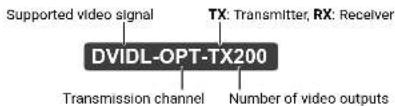
text_image
Supported video signal TX: Transmitter, RX: Receiver DVIDL-OPT-TX200 Transmission channel Number of video outputsAbout the Serial Number
Lightware devices contain a label indicating the unique serial number of the product. The structure is the following:
Year of the manufacturing (3-9, A-Y):
7=2017,8=2018,9=2019,A=2020,etc...

Month of the manufacturing (1-9, A-C):
1=January, 2=February, ..., C=December
1.2. Box Contents
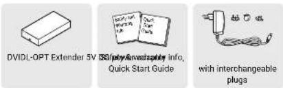
text_image
DVIDL-OPT Extender 5V USB drive with supply info, Quick Start Guide with interchangeable plugs1.3. Compatible Devices
Transmitter
The DVIDL-OPT-TX200 transmitter is compatible with the following receiver and input board:
• DVIDL-OPT-RX100 receiver;
- MX-FR modular frames with MX-DVIDL-OPT-IB-NT card.
Receiver
The DVIDL-OPT-RX100 receiver is compatible with the following transmitter and output board:
• DVIDL-OPT-TX200 receiver,
- MX-FR modular frames with MX-DVIDL-OPT-OB-NT card.
1.4. Features of the Extenders

Supports 4K Resolutions
Transmitting Dual-Link video signals up to 4096x2400 resolution, including all standard HDTV resolutions. Unencrypted signals up to 330 MHz pixel clock frequency (up to 165 MHz TMDS clock frequency).

Single-Link Operation Mode with One Fiber
When Single-Link DVI signal is transmitted, all of the high-speed TMDS data lanes are transmitted using only one multimode 50/125 fiber optical cable.

Neutrik OpticalICON Fiber Connector
Neutrik NO2-4FDW type LC-Duplex connector, eliminates its inherent weakness, guaranteeing a safe, dust protected, and durable connection.

Zero Frame Delay
DVIDL-OPT-TX200 add no frame noticeable delay to the switched signal. There is no frame or line period delays to the signals when passing a Lightware router.

Advanced EDID Management
The user can emulate any EDID on the inputs independently, read out and store any attached monitor's EDID in 100 internal memory locations.

Galvanic Isolation between Source and Display
Lightware fiber optical extenders are isolated between transmitter and receiver to eliminate ground loop noise or HUM effects.

Front Panel LEDs
Source-, signal-, monitor- and laser detection, to get immediate feedback about the status of connected devices.

USB Control
Input/output status, EDID Management, and hardware information can be accessed with Lightware Device Controller software via USB connection. Firmware upgrade can also be performed over this interface.

Locking DC Connector
Special locking plug of wall adaptor ensures safe power supply. This type of connector prevents accidental disconnections.

Front Panel Control (Transmitter)
EDID address selection with two decimal rotary switches and LEARN button are available for Advanced EDID Management.

Local Monitor Output (Transmitter)
The user can attach a local monitor to observe the video signal sent through the fiber optical cable. The resolution and clock frequency are the same on DVI and fiber optical connectors.

TMDS Reclocking (Receiver)
Removes jitter caused by long cables; the output has a clean, jitter free signal, eliminating signal instability and distortion caused by long cables or connector reflections.
1.5. Typical Applications
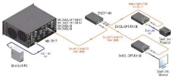
flowchart
graph TD
    A["Device"] -->|MX-NDL-OFT-RX100 MX-NDL-OFT-RX100 MX-NDL-B MX-NDL-B| B["SP23P-N1"]
    B --> C["EVOL-OFT-RX100"]
    C --> D["Dual Link Processor"]
    D --> E["DwCL-OFT-FX100"]
    E --> F["Dual Link Monitor"]
    G["Mix PC7"] -->|MX-NDL-OFT-RX100 MX-NDL-OFT-RX100 MX-NDL-B MX-NDL-B| H["SP23P-N1"]
    H --> I["Dual Link Processor"]
    I --> J["DwCL-OFT-FX100"]
    J --> K["Dual Link Monitor"]
Integrated System Diagram
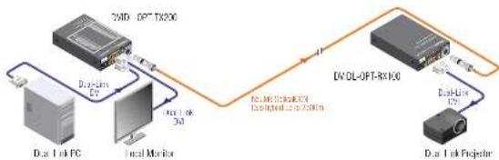
flowchart
graph LR
    A["Dus Link PC"] -->|Dual Link 2D| B["DVOL-OPT-RX100"]
    B -->|Dual Link 12V| C["Dus Link Projector"]
    B -->|Internal Link 3D| D["Local Monitor"]
    D -->|Internal Link 2D| B
    B -->|Internal Link 12V (Interrupted to control)| E["DVOL-OPT-RX100"]
    E -->|Control| F["DVOL-OPT-RX100"]
    F -->|Control| G["DVOL-OPT-RX100"]
    G -->|Control| H["DVOL-OPT-RX100"]
    H --> I["DVOL-OPT-RX100"]
Standalone Application Diagram
2
Installation
This chapter is about the installation of the device and connecting to other appliances, presenting also the mounting options and further assembly steps.
▶RACK SHELF MOUNTING
▶ CONNECTING STEPS
2.1. Rack Shelf Mounting
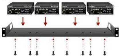
To mount the extenders Lightware supplies an optional accessory for rack mounting. The 1U high rack shelf is ideal way to fix two half-rack sized or four quarter-rack sized devices. The DVIDL-OPT series extenders have two mounting holes with inner thread on the bottom side; see the bottom view in the Mechanical Drawings section.

1U high rack shelf
INFO: 1U high rack shelf can be ordered at Lightware, please contact sales@lightware.com.
Mounting Steps
Step 1. Turn the unit upside down.
Step 2. Put the rack shelf upside down on the unit, and position it to get the mounting holes aligned.
Step 3. Fasten the unit on the rack shelf with the provided screws.
Step 4. Mount the rack shelf in the rack.
flowchart
graph TD
    A["服务器1"] --> B["数据采集"]
    C["服务器2"] --> D["数据处理"]
    E["服务器3"] --> F["数据存储"]
    G["服务器4"] --> H["数据输出"]
    style A fill:#f9f,stroke:#333
    style C fill:#f9f,stroke:#333
    style E fill:#f9f,stroke:#333
    style G fill:#f9f,stroke:#333
Mounting of four extenders to a 1U high rack shelf
WARNING! Always use the supplied screws. Using different (e.g. longer) ones may cause damage to the device.
INFO: The extenders are quarter-rack sized.
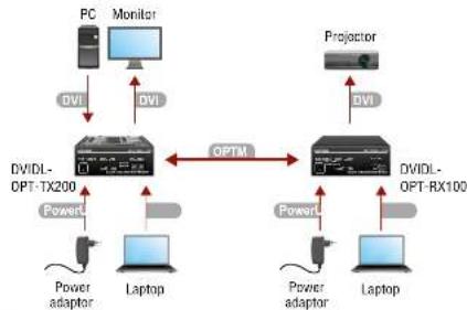
2.2. Connecting Steps
flowchart
graph TD
    PC["PC"] -->|DVI| Monitor["Monitor"]
    Monitor -->|DVI| Projector["Projector"]
    Projector -->|DVI| DVIDL-Opt-TX200["DVIDL-OPT-TX200"]
    DVIDL-Opt-TX200 -->|OPTM| DVIDL-Opt-RX100["DVIDL-OPT-RX100"]
    PowerL["PowerL"] -->|DVI| DVIDL-Opt-TX200
    PowerL -->|DVI| DVIDL-Opt-RX100
    Laptop1["Laptop"] -->|DVI| DVIDL-Opt-TX200
    Laptop1 -->|DVI| DVIDL-Opt-RX100
    Laptop2["Laptop"] -->|DVI| DVIDL-Opt-TX200
    Laptop2 -->|DVI| DVIDL-Opt-RX100
WARNING! Do not look directly into the LC fiber optical connector if the cable is connected to the transmitter only and the laser is active!

Connect a multimode (OPTM) fiber cable to the channel A of the transmitter.
Connect a multimode (OPTM) fiber cable to the channel B of the receiver.

Connect the source (e.g. a PC) to the input port of the transmitter by a DVI cable.
Optionally connect a local display (e.g. monitor) to the output port of the transmitter.
Connect the sink (e.g. a projector) to the output port of the receiver by a DVI cable.

Optionally connect a controller device (e.g. laptop) to the USB port of the desired extender.

Firstly connect the power adaptor to the DC input of the extender, then to the AC power socket.
ATTENTION! Pay attention to the DVI cable, if dual-link signal is to be sent, use only dual-link DVI cables.
3
Product Overview
The following sections are about the physical structure of the device, input/output ports and connectors.
▶FRONT VIEW (TRANSMITTER)
▶REAR VIEW (TRANSMITTER)
▶FRONT VIEW (RECEIVER)
▶ REAR VIEW (RECEIVER)
▶ELECTRICAL CONNECTIONS
3.1. Front View (Transmitter)
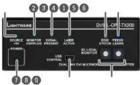
text_image
2 3 4 1 5 6 LIGHTWARE DVI-LOF-TX200 SOURCE ON/OFF MONITOR HOTR/POL SIGNAL PRESENT LABOR ACTIVE USB CONTROL TUAL LED ON/OFF MULTIPACK 7 8 9 RSB PRESS STATUS LEARN ATTER1 Source +5V LED The LED indicates if a DVI source is connected to the unit, it is powered on and sends 5V signal to Pin 14 of the input DVI connector.
2 Monitor Hotplug LED The LED indicates if a display device (or repeater, etc.) is connected to the corresponding DVI output and it sends a valid Hot Plug Signal on Pin 16 through the DVI cable.
3 Signal Present LED Indicates when a valid DVI signal is detected on the DVI INPUT connector.
4 Laser Active LED Indicates when the laser driver is enabled to help avoid accidentally looking into the laser beam.
5 EDID Status LED Shows the status of the selected EDID and gives feedback about EDID learning. See more information in the EDID status LED section.
6 Learn button Stores the EDID of the display device attached to the OUTPUT. See more information in the Learning EDID section.
7 Power LED Power LED lights green when the unit is powered on. It does not indicate whether the device is operating properly.
8 USB connector Advanced EDID management (in LDC software) and firmware upgrade are available via the USB interface. Use an USB cable with mini-B male connector.
9 EDID rotary switches The rotary switches select one of the EDID memory addresses. Use a flat head screwdriver that fits into the actuator. Avoid the use of keys, coins, knives and other sharp objects because they might cause permanent damage to the rotary switches. See more information about EDID change in the Switching EDID section.
3.2. Rear View (Transmitter)
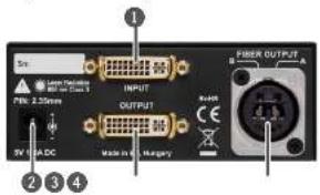
text_image
Snr. Laser Television R10.25mm PWR: 2.35mm OUTPUT B A HAPPY PROX OUTPUT B A R C E M H V ADC Made in H Hungary ① ② ③ ④1 DVI input
29 pole DVIH connector, however only digital pins are internally connected. Connect single link or dual-link DVI source with an applicable DVI cable, use a dual-link DVI cable when dual-link signal to be transmitted. The unit has minimal cable compensation ability, hence the maximum recommended cable length is 10 m. See the DVI Inputs and Outputs section for more information.
2 5V DC Input
5V DC input for local powering. The power LED on the front indicates the proper supply voltage. See more information about the power connector in the DC 5V Connection section.
3 DVI output
29 pole DVI connector, however only digital pins are internally connected. A local display device can be connected to monitor the outgoing signal. The resolution and pixel clock frequency are the same on the DVI and Neutrik connectors, no internal scaling or conversion is applied to the signal. The OUTPUT connector is able to supply 500 mA current on pin 14 to power fiber optical extenders like DVI-OPT-TX100. See the DVI Inputs and Outputs section for more information about DVI connector.
4 Neutrik connector
Neutrik NO2-4FDW type LC duplex connector. Two channels are used for signal transmitting: "Channel A" is used when single link video signal is connected, while both "A" and "B" channels are used when dual-link video signal is connected to the input. See the Fiber Optical Connector section for more information.
3.3. Front View (Receiver)
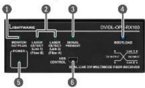
text_image
LIGHTWARE DVDL-OF-RX100 MAIN/THYPOLE POWER LASS DINJ 2.5 (Fiber B) LASS DINJ 2.5 (Fiber A) RELIAL RADIUM CONTROL BELL LARK OF MULTIMETER FLASH RECOVATOR BOOTLOAD 1 2 3 4 5 61 Monitor LED The
LED indicates if a display device (or repeater, etc.) is connected to the corresponding DVI output and it sends a valid Hot Plug Signal on Pin 16 through the DVI cable.
2 Laser LEDs The L
EDs indicate if a laser beam is detected on fiber connector "channel A" and "channel B".
3 Signal LED
Indicates if a valid DVI clock signal can be recovered from the fiber optical signal.
4 Bootload
The receiver can be switched into bootload mode (firmware upgrade) manually. See more information in the Detailed Instructions section.
5 Power LED
Green LED indicates if the device is powered on. It does not indicate whether the device is operating properly.
6 USB connector
Advanced EDID management (in LDC software) and firmware upgrade are available via the USB interface. Use an USB cable with mini-B male connector.
3.4. Rear View (Receiver)
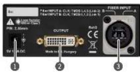
text_image
Pin: 2.36mm S/N A/DC OUTPUT Made in E1 Surgery Pin: INPUT A: CLK TWD04.4.5(146.3) Pin: INPUT B: CLK TWD05.1(2.14.1) FIRE INPUT A B C D E F G H I J K L M N O P Q R S T U V W X Y Z A B C D E F G H I J K L M N O P Q R S T U V W X Y Z1 5V DC input
5V DC input for local powering. The power LED on the front indicates the proper supply voltage. See more information about the power connector in the DC 5V Connection section.
2 DVI output
29 pole DVI connector, however only digital pins are internally connected. Connect single link or dual-link DVI display according to the signal with an applicable DVI cable. The maximum recommended cable length is 10 m. The OUTPUT connector is able to supply 500 mA current on pin 14 to power fiber optical extenders like DVI-OPT-TX100. See the DVI Inputs and Outputs section for more information about DVI connector.
3 Neutrik connector
Neutrik NO2-4FDW type LC duplex connector. Two channels are used for signal transmitting: "Channel B" is used when single link video signal is connected, while both "A" and "B" channels are used when dual-link video signal is connected to the input. See the Fiber Optical Connector section for more information.


Product Overview DVIDL-OPT series - User's Manual 10
3.5. Electrical Connections
3.5.1. DC 5V Connection
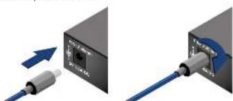
The device has locking DC connector to establish robust and safe power connection. After plugging it in, turn the plug clockwise as you can see in the picture below.
natural_image
Two diagrams showing cable connection to a device, one with blue arrows indicating direction (no text or symbols present)Locking DC connector
Do not forget to turn the connector counterclockwise before trying to disconnect the power adaptor.
WARNING! Always use the supplied 5V power adaptor or Lightware's rack mountable power supply units. Warranty is void if damage occurs due to use of a different power source.
3.5.2. DVI Inputs and Outputs
DVIDL-OPT-TX200 and DVIDL-
OPT-RX100 provide 29 pole ,digital
only* DVI-I Dual-Link connectors
(only digital pins are internally connected). This way, users can plug in any DVI connector, but keep in mind that analog signals (such as VGA or RGBHV) are not processed.
Always use high quality DVI cable for connecting sources and displays. Pay attention to the DVI cable, if dual-link signal is to be sent, use only dual-link DVI cables.
Fiber Cable Powering
As a special feature, the device is able to supply 500 mA current on DDC +5V output (pin 14 on the output connectors) to power fiber optical DVI transmitters. Standard DVI outputs or VGA cards supply only 55 mA current on +5V output, thus unable to power directly a fiber optical cable.
3.5.3. Fiber Optical Connector
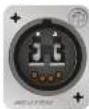
The Neutrik OpticalCON connector has two fiber channels, "channel A" and "channel B". When single link video signal is sent, only one channel is used (from "channel A" on transmitter to "channel B" on receiver). When dual-link signal is sent, both channels are used for signal transmitting.
Maximum fiber cable extension distances can be found in the Maximum Fiber Cable Extensions section.
3.5.4. USB Connector
The DVIDL-OPT series extenders provide standard USB mini B-type connector for software control and firmware upgrade purposes.


Operation
This chapter is about the powering and operating of the device describing the functions which are available by the front/rear controls.
POWERING ON
▶ABOUT THE EDID MEMORY (TRANSMITTER)
▶FRONT PANEL OPERATION (TRANSMITTER)
4.1. Powering On
When building an electronic system, make sure that all of the devices are powered down before connecting them. Powered on devices may have dangerous voltage levels that can damage sensitive electronic circuits. After the system is complete, connect and fix the DC power cable to the extender unit and then to the power outlet. The unit is immediately powered ON.
After the extender units are initialized, the attached DVI source and monitor can be powered on.
ATTENTION! The laser becomes enabled any time the transmitter is powered on, disregarding that it was disabled before or not. This is done to avoid accidental laser loss problems.
INFO: If the power LED does not light up upon power-up, the unit is most likely damaged and further use is not advised. Please contact support@lightware.com.
4.2. About the EDID Memory (Transmitter)
The EDID memory is non-volatile and can store 99 EDIDs. The memory structure is as follows:
| Description Rotary switch state | Memory bank number in LDC |
| Factory Preset EDID list #01 - #60 F01 - F60 | |
| User programmable slots #61 - #99 U1 - U39 | |
| Last attached monitor's EDID (local monitor) | #00 D01 - D02 |
INFO: DVIDL-OPT-TX200 can handle both 128 Byte EDID and 256 Byte extended EDID structures.
INFO: The attached monitor's EDID is stored automatically, until a new monitor is attached to the local monitor output. In case of powering the unit off, the last attached monitor's EDID remains in non-volatile memory.
Factory Preset EDIDs
The factory EDIDs (01-60) are factory preprogrammed and cannot be modified. These are the most common resolutions. They are specially provided to force graphic cards to output only the exact pixel resolution and refresh rate. Universal DVI (29) allows multiple resolutions including all common VESA defined resolutions. The use of universal EDID is recommended for fast and easy system setup. You can find the whole list in the Factory EDID List section.
INFO: Factory EDIDs do not include HDMI support. If you need audio, you can create an EDID with HDMI support with the Easy EDID Creator and upload it to user EDID memory. See the Creating an EDID section for more information.
4.3. Front Panel Operation (Transmitter)
4.3.1. Switching EDID
The user can select an EDID to emulate on the input, this is called EDID routing. There are two types of the emulation: static and dynamic.
- Static EDID emulation happens, when an EDID from the Factory or User EDID list is routed to an input.
- Dynamic EDID emulation occurs, when an attached monitor's EDID is routed to an input. In this case the emulated EDID changes automatically, if a new monitor is attached to the output, by simply copying the data from the monitor.
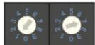
Use a screwdriver to change the memory address on the rotary switches on the front side of the DVIDL-OPT-TX200. The left switch sets the tens value, the right switch gives the ones value of the EDID. (Location #17 is selected by the rotary switches in the current example.) After
- A. It is selected by the rotary switches in the either one of the rotary switches has been rotated the unit waits approximately two seconds before the selected EDID becomes active. Check the status of the device:
| EDID status LED | Description |
| (ON - green) | The selected EDID memory is valid. |
| (ON - red) | The selected EDID memory is invalid (wrong address / empty user memory). |
Address #00 has a special function. If a monitor is connected to the OUTPUT, then its EDID is copied to the INPUT connector. If no monitor is connected to the OUTPUT then the EDID copied to the INPUT connector is the EDID of the last connected monitor.
INFO: If an invalid EDID is selected, DVIDL-OPT-TX200 does NOT change the emulated EDID on the input. Last valid EDID is kept until another valid EDID is selected to emulate on the input.
INFO: After every EDID change, DVIDL-OPT-TX200 toggles the HOT PLUG signal for approximately 2 seconds. Some graphics cards or DVD players do not sense the HOT PLUG signal, and even if EDID has been changed, the set resolution is not affected. In this case the source device must be restarted, or powered OFF and ON again.


- Operation DVIDL-OPT series - User's Manual 12
4.3.2. Learning EDID
The factory preset EDIDs cannot be changed by the user. Only addresses from #61 to #99 are user programmable.
Step 1. After connecting the sink device to OUTPUT, use a screwdriver to select a user programmable memory address on the rotary switches. If the Status LED is illuminated red, then the memory slot is empty and ready to be programmed. If it is green, the memory was already used before, but still available for reprogramming.
Step 2. Push the LEARN button on the front side of DVIDL-OPT-TX200 and hold it down for approximately two seconds. If the teaching is successful, the Status LED blinks four times green, if the teaching is unsuccessful, the Status LED blinks four times red.
Step 3. The normal function of the LED is in effect.
INFO: If DVIDL-OPT-TX200 is unable to read the monitor's EDID or there is no currently attached monitor, the last attached monitor's valid EDID will be stored in the user memory. INFO: If the selected user memory is not empty, the new EDID will overwrite the previously stored EDID.
4.3.3. Deleting EDID
EDID cannot be deleted by the controls on the front panel, only by Lightware Device Controller software. See more information in the EDID Operations section.
4.3.4. EDID status LED
The LED shows the status of the selected EDID and gives feedback about EDID learning as follows:
| EDID status LED | Description |
| Valid EDID is selected. | |
| Invalid EDID is selected (the location is empty or the rotary switch is in wrong position). | |
| Valid EDID stored successfully (after EDID learning). | |
| Invalid EDID, storing is not successful (after EDID learning). | |
| Transmitter is in bootload mode (firmware upgrade). See more information in the Detailed Instructions section. |
5
Software Control - Lightware Device Controller
The device can be controlled by a computer through the USB port using Lightware Device Controller (LDC). The software can be installed on a Windows PC or Mac OS X. The application and the User's manual can be downloaded from www.lightware.com. The Windows and the Mac versions have the same look and functionality.
INSTALL AND UPGRADE
▶ CONNECTING TO A DEVICE (DEVICE DISCOVERY WINDOW)
▶I/O PARAMETERS MENU - TRANSMITTER
▶I/O PARAMETERS MENU - RECEIVER
THE EDID MENU
▶EDITING AN EDID
▶ SETTINGS MENU
▶ TERMINAL WINDOW
5.1. Install and Upgrade
INFO: After the installation, the Windows and the Mac application has the same look and functionality. This type of the installer is equal with the Normal install in the case of Windows and results an updateable version with the same attributes.
Installation for Windows OS
Run the installer. If the User Account Control drops a pop-up message click Yes. During the installation you will be prompted to select the type of the installation: normal and the snapshot install:
| Normal install Snapshot install | |
| Available for Windows and Mac OS | Available for Windows |
| The installer can update only this instance | Cannot be updated |
| Only one updateable instance can exist for all users | Different versions can be installed for all users |
Comparison of installation types
ATTENTION! Using the Normal install as the default value is highly recommended.
Installation for Mac OS
Mount the DMG file with double clicking on it and drag the LDC icon over the Applications icon to copy the program into the Applications folder. If you want to copy the LDC into another location just drag the icon over the desired folder.
Upgrading of LDC
text_image
Information Current version: 1.13.063 Update version: 1.14.063 Options Check for updates automatically: Remind me later: Next time Proxy settings: Setup Check now Download update PostponeStep 1. Run the application
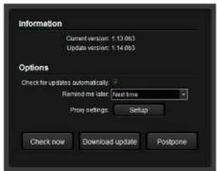
The Device Discovery window appears automatically and the program checks the available updates on Lightware's website and opens the update window if the LDC found updates. The current and the update version number can be seen at the top of the window and they are shown in this window even with the snapshot install. The Update window can be also opened by clicking the ⑦ and the Update button.
Step 2. Set the desired update setting in the Options section.
When the Check for updates automatically option is selected, the LDC tries to find a new version after startup The update can be postponed by setting a reminder; use the drop down list. The proxy settings can be set in a separate window.
Step 3. Click the Download update button to start. The updates can be checked manually by clicking the Check now button.


- Software Control - Lightware Device Controller DVIDL-OPT series - User's Manual 14
5.2. Connecting to a Device (Device Discovery Window)
There are three tabs for the different type of interfaces: Ethernet, Serial, and USB.
The Ethernet tab consists of two lists:
- Favorite devices: You can add any Lightware device that is connected via Ethernet and no need to browse all the available devices.
- All devices: The Lightware devices are listed which are available in the network.
Further Tools
The Tools menu contains the following options:
- Log viewer: The tool can be used for reviewing previously saved log files.
- Create EDID: This tool opens the Easy EDID Creator wizard which can be used for creating unique EDIDs in a few simple steps. Functionality is the same as the Easy EDID Creator, for the detailed information see the Creating an EDID section.
- Demo mode: This is a virtual MX-FR17 matrix router with full functionality built into the LDC. Functions and options are the same as a real MX-FR17 device.
The Terminal window is also available by pressing its button on the bottom.
Establishing the Connection
Select the unit from the USB devices; double click on the device or select it and click on the green Connect button.
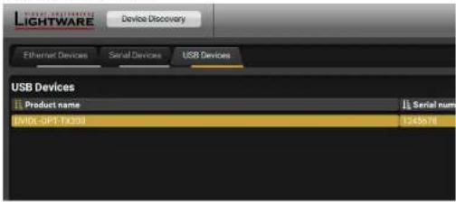
text_image
LIGHTWARE Device Discovery Ethernet Devices Serial Devices USB Devices USB Devices Product name Serial num EVIDL-OPT-10209 1245b/11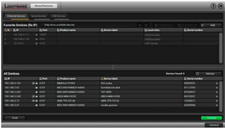
text_image
Lightware Device Discovery Ethernet Devices Serial Devices USB Devices Favorite Devices (fix IP) Only show available devices Add N IP Port Product name Device label Local alias Serial number 1 192.168.0.111 10001 Add local alias 2 192.168.0.100 6107 Add local alias 3 127.0.9.1 6107 LWR Device All Devices Devices found: 6 Refresh IP Port Product name Device label Serial number 192.168.3.123 6107 MMX4x2-HT200 GUI szobe 00005031 192.168.2.62 6107 MX2-8X8-HDM20-AUDIO SomeDeviceLabel 81112563 192.168.2.204 6107 MX2-8X8-HDM20-AUDIO TST-DRG 97654321 192.168.3.243 6107 UBLX-MMU-X200 UBLX-MMU-X200 86122857 192.168.2.72 6107 UMX-TPS-TX140 UMX-TPS-TX120 12345671 192.168.3.47 6107 MX2-8X8-HDM20-AUDIO modes qyartias 6A085966 Tools Connect TerminalThe Device Discovery Window


- Software Control - Lightware Device Controller DVIDL-OPT series - User's Manual 15
5.3. I/O Parameters Menu - Transmitter
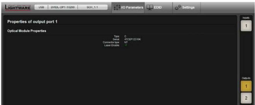
The menu displays the current state of the device. The input port of the device is on the right top, the output ports are on the right bottom side. The properties of input port is displayed as default.
Output Ports (Optical and Local DVI)
The Output 1 is the optical module, the Output 2 is the local DVI output port. The laser can be enabled or disabled in the Output 1 menu.
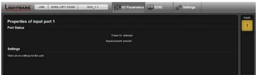
text_image
LIGHTWARE USB OVIDL-CPT-TX200 SCH_1.1 I/O Parameters EDID Settings Properties of input port 1 Port Status Power HV: detected Signal present: present Settings There are no settings for this portDVI Input Port Window (TX)
text_image
LIGHTWARE USB DVDL OPT-1X200 SCH_1.1 I/O Parameters EDID Settings Properties of output port 1 Optical Module Properties Type C Serial 4TCEP12310K Connector type NT Label Enable Inputs 1 Outputs 1 2Optical Output Port Window (TX)


- Software Control - Lightware Device Controller DVIDL-OPT series - User's Manual 16
5.4. I/O Parameters Menu - Receiver
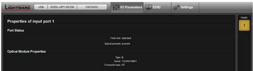
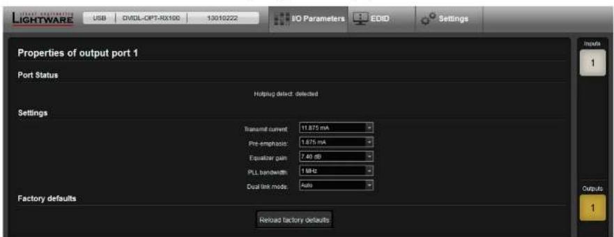
The menu displays the current state of the device. The input port of the device is on the right top, the output ports are on the right bottom side. The properties of input port is displayed as default.
DVI Output Port
If the received signal is dual-link DVI, the Dual-link mode settings is recommended to set to Enabled for the proper operation.
ATTENTION! Changing of Transmit current, Pre-emphasis, Equalizer gain, and PLL bandwidth settings is recommended for experienced users only.
text_image
LIGHTWARE USB OVIDL-OPT-RX100 13010222 IO Parameters EDID Settings Properties of input port 1 Port Status Filter link: detected Signal present: present Optical Module Properties Type B Serial 12345678991 Connector type NTOptical Input Port Window (RX)
text_image
LIGHTWARE USB CVIDL-CPT-RX100 13010222 IO Parameters EDID Settings Properties of output port 1 Port Status Hotplug defect: detected Settings Transmit current 11.875 mA Pre-emphas: 1.675 mA Equistar gain 7.40 dB PLL bandwidth 1 MHz Dual link mode Auto Factory defaults Reload factory defaults Inputs 1 Outputs 1DVI Output Port Window (RX)


- Software Control - Lightware Device Controller DVIDL-OPT series - User's Manual 17
5.5. The EDID Menu
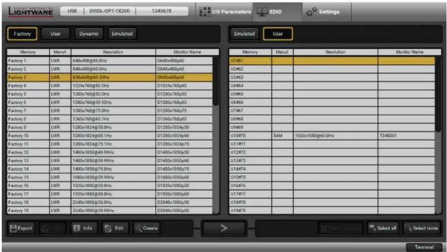
The Advanced EDID Management is available in the EDID menu. There are two panels: left one contains Source EDIDs, right one contains Destination places where the EDIDs can be emulated or copied.
Sources and Destinations
• Factory EDID list shows the pre-programmed EDIDs (F1-F50).
- Dynamic EDID list shows the display device connected to the device's outputs. The unit stores the last display devices' EDID on either output, so there is an EDID shown even if there is no display device attached to the output port at the moment.
- User memory locations (U1 - U50) can be used to save custom EDIDs.
- Emulated EDID list shows the currently emulated EDID for the inputs. The source column displays the memory location that the current EDID was routed from.
The source reads the EDID from the Emulated EDID memory on the INPUT port. Any EDID from any of the User/Factory/Dynamic EDID lists can be copied to the user memory.
EDID Emulation Types
- Static EDID emulation: an EDID from the Factory or User EDID list is selected. Thus, the Emulated EDID remains the same until the user emOulates another EDID.
- Dynamic EDID emulation: it can be enabled by selecting a slot from the Input 1..Input 16 EDID memory. The attached monitor's EDID is copied to the input; if a new monitor is attached to the output, the emulated EDID changes automatically.
text_image
LIGHTWARE USB | DVD-OFI-7X200 1245678 I/O Parameters EDID Settings Factory User Dynamic Emulated Memory Manuf Resolution Monitor Name Memory Manuf Resolution Monitor Name Factory 1 LWR 840x480g60.0Hz D840x480p60 U14961 Factory 2 LWR 846x486g60.0Hz D846x486p60 U24962 Factory 3 LWR 890x600g60.3GHz D890x600p60 U34963 Factory 4 LWR 1024x768g60.0Hz D1024x768p60 U44964 Factory 5 LWR 1280x768g50.0Hz D1280x768p50 U54965 Factory 6 LWR 1280x768g59.92Hz D1280x768p60 U64966 Factory 7 LWR 1280x768g75.0Hz D1280x768p75 U74967 Factory 8 LWR 1360x768g60.1Hz D1360x768p60 U84968 Factory 9 LWR 1380x1024g50.0Hz D1380x1024p50 U94969 Factory 10 LWR 1280x1024g60.1Hz D1280x1024p60 U10470 SAM 1920x1080g60.0Hz T248301 Factory 11 LWR 1280x1024g75.1Hz D1280x1024p75 U114971 Factory 12 LWR 1400x1050g49.9Hz D1400x1050p50 U124972 Factory 13 LWR 1400x1050g59.9Hz D1400x1050p60 U134973 Factory 14 LWR 1480x1050g75.0Hz D1480x1050p75 U144974 Factory 15 LWR 1680x1050g59.9Hz D1680x1050p60 U154975 Factory 16 LWR 1920x1080g50.0Hz D1920x1080p50 U164976 Factory 17 LWR 1920x1080g60.0Hz D1920x1080p60 U174977 Factory 18 LWR 2048x1080g50.0Hz D2048x1080p50 U184978 Factory 19 LWR 2048x1080g59.9Hz D2048x1080p60 U194979 Export Info Edit Create > Select all Select none TerminalEDID menu
Control Buttons

Exporting an EDID (save to a file)

Opening the Advanced EDID Editor with the selected EDID

Deleting an EDID (from the User memory)

Importing an EDID (load from a file)

Opening Easy EDID Creator

Selecting all memory places in the right panel Selecting none of the memory places in the right panel

Displaying the EDID Summary window

Executing EDID emulation or copying (Transfer button)


- Software Control - Lightware Device Controller DVIDL-OPT series - User's Manual 18
5.5.1. EDID Operations
Changing the Emulated EDID
Step 1. Choose the desired EDID list (source panel) and select an EDID.
Step 2. Press the Emulated button on the top of the Destination panel.
Step 3. Select the desired ports on the right panel (one or more ports); the EDID(s) will be highlighted with a yellow cursor.
Step 4. Press the Transfer button to change the emulated EDID.
Learning an EDID
The process is the same as changing the emulated EDID, the only difference is the Destination panel: press the User button. Thus, one or more EDIDs can be copied into the user memory either from the factory memory or from a connected sink (Dynamic).
Exporting an EDID
ATTENTION! This function is working on Windows and Mac OS X operating systems and under Firefox or Chrome web browsers only.
Source EDID can be downloaded as a file (*.bin, *.dat or *.edid) to the computer.
Step 1. Select the desired EDID from the Source panel (the line will be highlighted with yellow).
Step 2. Press the Save button to open the dialog box and save the file to the computer.
Importing an EDID
Previously saved EDID (*.bin, *.dat or *.edid file) can be uploaded to the user memory:
Step 1. Press the User button on the top of the Source panel and select a memory slot.
Step 2. Press the Upload button below the Source panel
Step 3. Browse the file in the opening window then press the Open button. Browsed EDID is imported into the selected User memory.
ATTENTION! The imported EDID overwrites the selected memory place even if it is not empty.
Deleting EDID(s)
The EDID(s) from User memory can be deleted as follows:
Step 1. Press User button on the top of the Destination panel.
Step 2. Select the desired memory slot(s); one or more can be selected (Select All and Deselect All buttons can
be used). The EDID(s) will be highlighted with yellow.
Step 3. Press the Delete selected button to delete the EDID(s).
5.5.2. EDID Summary Window
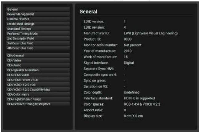
Select an EDID from Source panel and press Info button to display EDID summary window.
text_image
General Power Management Gamma / Colors Established Timings Standard Timings Preferred Timing Mode 2nd Descriptor Field 3rd Descriptor Field 4th Descriptor Field CEA General CEA Video CEA Audio CEA Speaker Allocation CEA HDMI VSDB CEA HDMI Forum VSDB CEA YDSC 4.2.0 VDB CEA YDSC 4.2.0 Capability Map CEA Colorimetry CEA High Dynamic Range CEA Detailed Timing Descriptors General EDID version: 1 EDID revision: 4 Manufacturer ID: LWR (Lightware Visual Engineering) Product ID: 0000 Monitor serial number: Not present Year of manufacture: 2010 Week of manufacture: 16 Signal interface: Digital Separate Sync H&V: Composite sync on H: Sync on green: Serration on VS: Color depth: Undefined Interface standard: HDMI b is supported Color spaces: RGB 4.4.4 & YCrCb 4.2.2 Aspect ratio: 0 Display size: 0 cm X 0 cm


- Software Control - Lightware Device Controller DVIDL-OPT series - User's Manual 19
5.6. Editing an EDID
Select an EDID from Source panel and press Edit button to display Advanced EDID Editor window. The editor can read and write all descriptors, which are defined in the standards, including the additional CEA extension. Any EDID from the device's memory or a saved EDID file can be loaded into the editor.
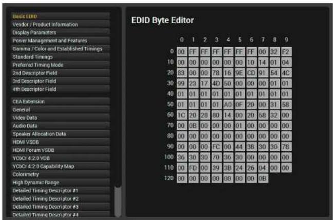
text_image
Basic EMD Vendor / Product Information Display Parameters Power Management and Features Gamma / Color and Established Timings Standard Timings Preferred Timing Mode 2nd Descriptor Field 3rd Descriptor Field 4th Descriptor Field CEA Extension General Video Data Audio Data Speaker Allocation Data HDMI VSDB HDMI Forum VSDB YCBD 4.2.9 VDB YCBD 4.2.9 Capability Map Colorimetry High Dynamic Range Detailed Timing Descriptor #1 Detailed Timing Descriptor #2 Detailed Timing Descriptor #3 Detailed Timing Descriptor #4 EDID Byte Editor 0 1 2 3 4 5 6 7 8 9 00 FF FF FF FF FF FF 00 32 F2 10 00 00 00 00 00 10 14 01 04 20 83 00 00 78 16 9E CD 91 54 4C 30 99 23 17 40 50 00 00 00 01 01 40 01 01 01 01 01 01 01 01 01 01 50 01 01 01 A0 OF 20 00 31 58 60 1C 20 28 80 14 00 20 58 32 00 70 00 9B 00 00 00 01 00 00 00 00 80 00 00 00 00 00 00 00 00 00 00 90 00 9B FC 00 44 38 30 30 78 100 36 30 30 70 36 39 00 00 00 00 110 00FD 39&3B 24&26&44&46 120 00 9B&9BThe EDID Editor Window
The software resolves the raw EDID and displays it as readable information to the user. All descriptors can be edited, and saved in an EDID file, or uploaded to the User memory. For more details about EDID Editor please download the EDID Editor Application Notes document.
5.6.1. Creating an EDID
Since above mentioned Advanced EDID Editor needs more complex knowledge about EDID, Lightware introduced a wizard-like interface for fast and easy EDID creation. With Easy EDID Creator it is possible to create custom EDIDs in four simple steps.
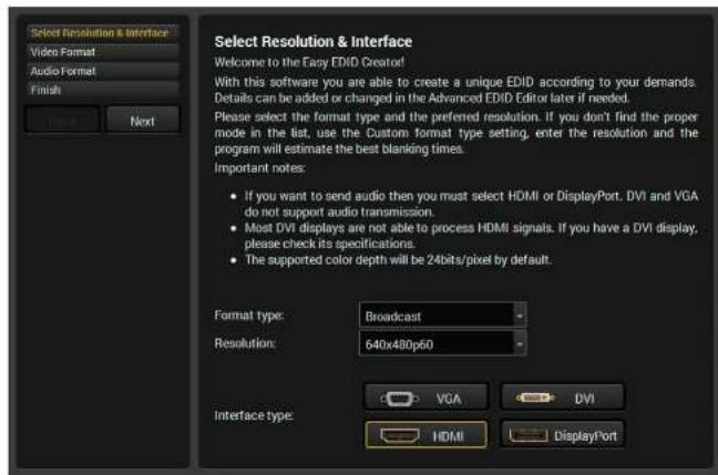
text_image
Select Resolution & Interface Video Format Audio Format Finish Next Select Resolution & Interface Welcome to the Easy EDID Creator! With this software you are able to create a unique EDID according to your demands. Details can be added or changed in the Advanced EDID Editor later if needed. Please select the format type and the preferred resolution. If you don't find the proper mode in the list, use the Custom format type setting, enter the resolution and the program will estimate the best blanking times. Important notes: • If you want to send audio then you must select HDMI or DisplayPort. DVI and VGA do not support audio transmission. • Most DVI displays are not able to process HDMI signals. If you have a DVI display, please check its specifications. • The supported color depth will be 24bits/pixel by default. Format type: Broadcast Resolution: 640x480p60 Interface type: VGA DVI HDMI DisplayPortThe Easy EDID Creator Window
By clicking on the Create button below Source panel, Easy EDID Creator is opened in a new window. For more details about EDID Editor please download the EDID Editor Application Notes document.


- Software Control - Lightware Device Controller DVIDL-OPT series - User's Manual 20
5.7. Settings Menu
5.7.1. Device Information Tab
Basic information is displayed about the device in this menu: Device type with serial number and the type of the installed boards with firmware and hardware version.
5.7.2. Log Tab
Generating a Standard Report File
LDC is able to collect information from the device and save it to a report file. This information package can be sent to Lightware when a problem may arise with the device. Download report
ATTENTION! When a report is necessary to generate, always let the devices be connected to the device, do not disconnect them. The Controller Software will collect information about the devices and about their status.
Step 1. Press the Download report button on the Log tab in the Settings menu:
Step 2. The Save as dialog box appears. Select the place where you want to save the report file. The default file name can be changed.
Step 3. LDC collects the needed information. When the process is finished, the folder is opened, where the file was saved. The report contains the following information:
• Device type and serial number.
- Firmware versions of all the internal controllers,
• All EDID headers and status (emulated, dynamic, factory, user),
Generating a Custom Report File
The Controller Software is able to send a custom command file to the device. The command file can be generated by Lightware support. This is needed when some special commands have to be used for configuring or troubleshooting.
This function is only for special troubleshooting cases.
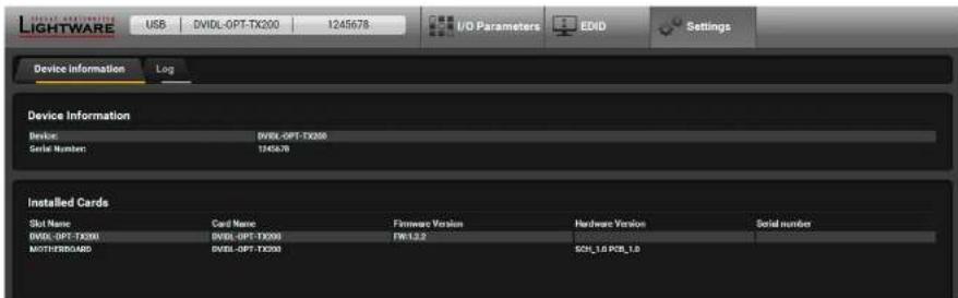
text_image
LIGHTWARE USB DVIDL-OPT-TX200 1245678 I/O Parameters EDID Settings Device Information Log Device Information Device: DVIDL-OPT-TX200 Serial Number: 1245678 Installed Cards Slot Name Card Name Firmware Version Hardware Version Serial number DVIDL-OPT-TX200 FWD 1.2.2 MOTHERBOARD DVIDL-OPT-TX200 SCH_1.0 PCB_1.0The Device Information Tab
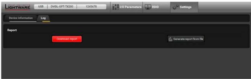
text_image
Lightware USB DVIDL-OPT-TX200 1245678 I/O Parameters EDID Settings Device Information Log Report Download report Generate report from fileThe Log Tab


- Software Control – Lightware Device Controller DVIDL-OPT series – User's Manual 21
5.8. Terminal Window
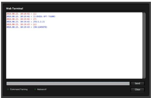
This general purpose terminal is intended mainly for testing and debugging purposes. When a successful connection is established with a router this terminal can be used either via the USB connection. All commands can be used here that are discussed in the Programmer's Reference chapter. The command text can be typed directly.
By default commands are automatically surrounded by framing brackets. Every sent command and every received response gets an arrow (-> or <-) prefix, and has different font colors in order to help to distinguish.
The timecode in every row shows the exact time when the command was sent or the response received.
If the Command framing checkbox is unchecked, you can send multiple commands together, however in this case you have to type in the framing brackets manually.
The terminal can be also opened after starting the LDC - press the Terminal button on the Device discovery page on the bottom of the window.
TIPS AND TRICKS: The typed commands can be 'browsed' when the cursor is in the command line and you press the up button on the keyboard. The commands are stored until the LDC is closed.
text_image
Web Terminal 2018.00.23. 10:19:42 > [1] 2018.00.23. 10:19:42 < (1:DVIDL -OPT -TK200) 2018.00.23. 10:19:42 > [F] 2018.00.23. 10:19:42 < (PA:1.2.2) 2018.00.23. 10:19:43 > [S] 2018.00.23. 10:19:43 < (SN:1245678) Send Command framing Autoscroll ClearThe Terminal Window


- Programmer's Reference DVIDL-OPT series - User's Manual 22

Programmer's Reference
The device can be controlled through a command set of protocol commands to ensure the compatibility with other Lightware products. The supported commands are described in this chapter.
▶PROTOCOL DESCRIPTION
▶STATUS COMMANDS
▶EDID ROUTER COMMANDS
▶COMMANDS – QUICK SUMMARY
INFO: The extenders support LW2 command protocol set only. LW3 command set is not supported. Lightware extenders have a special protocol, but to interoperate with third-party devices, a secondary protocol is also provided.
6.1. Protocol Description
The protocol description hereinafter stands for Lightware protocol.
The device accepts commands surrounded by curly brackets - {} - and responds data surrounded by round brackets - () - only if a command was successfully executed. All input commands are converted to uppercase, but respond commands can contain upper and lower case letters as well.
Legend for control commands:
| Format Explanation | |
| Location number in 1, 2 or 3 digit ASCII format | |
| id number in 1 or 2 digit ASCII format | |
| id number in 2 digit ASCII format | |
| Crlf Cramage return, Line feed (0x0D, 0x0A) | |
| • Space character (0x20) | |
| → | Each command issued by the controller |
| ← | Each response received from the router |
6.2. Status Commands
6.2.1. View Product Type
Description: Identification of the device. Type 'i' or 'l' then the device responds its name.
| Format Example | |
| Command {I} | → {I} |
| Response (I) | ← (I:DVIDL-OPT-TX200) |
Explanation: The connected device is a DVIDL-OPT-TX200.
6.2.2. View Serial Number
Description: The device responds its 8-digit serial number.
| Format Example | |
| Command {S} | {s} |
| Response (SN:)CrLf | (SN:3C019935) |
Legend: < SERIAL_N > shows the serial number of the device.
Explanation: The connected device's serial number is 3C019935.
6.2.3. View Firmware Version
Description: View the CPU firmware revision. To view other controller's firmware version see the {FC} command.
| Format Example | |
| Command (F) | (f) |
| Response (FW:CrLf | (FW:1.2.3) |
Legend: The firmware version is 1.2.3
6.2.4. Compile Time
Description: Shows the CPU firmware compile time.
| Format Example | |
| Command (CT) | → {ct} |
| Response (Compiled:)CrLf | ← (Compiled: Jan 27 2017 13:55:24) |
Legend:
| Identifier Parameter |
| Month, day and year |
| Hours, minutes and seconds |
Explanation: The firmware was made on 01.27.2017 at 13:55:24.
6.2.5. View Installed Board
Description: Shows the hardware name and revision of the installed board.
| Format Example | |
| Command (IS) | (is) |
| Response (SL#0•CrLf(SL•END)CrLf | ← (SL# SL# 0 DVIDL-OPT-TX200 SCH_1.0 PCB_1.0)← (SL END) |
Explanation: The device reports that it has an installed motherboard, the hardware revision is 1.0.
6.2.6. View Board Information
Description: Shows the firmware version and installed board together.
| Format Example | |
| Command {FC} | → {fc} |
| Response (CF-DESC>)Crlf(CF END)Crlf | ← (CF DVIDL-OPT-TX200 FW:1.2.3)← (CF END) |
Explanation: The device has an installed motherboard, the firmware version is 1.2.3.
6.2.7. View All Port Status
Description: Shows the actual status of all input and output ports.
| Format Example | |
| Command (PS) | → {ps} |
| Response (PS,OUTPUT_D)CrLf | ← (PS 3,01) |
Explanation: Video signal is present on the input, display device is connected to the second output.
Legend for the Transmitter:
| Bit values 0 | 1 | 2 | 3 | |
| INPUT_D | No signal | Source +5V | - | Signal detected |
| OUTPUT_D | No signal | - | Hotplug detected | - |
Legend for the Receiver:
| Bit values | 0 | 1 | 3 |
| INPUT_D | No signal | - | Signal detected |
| OUTPUT_D | No signal | Hotplug detected | - |
- Source +5V: The connected source sends +5V.
• Signal detected: Video signal is present (TMDS stream can be recognized). - Hotplug detected: Sink is connected to the output.
6.2.8. Restart the Device
Description: The device can be restarted without unplugging the power source.
Explanation: The device reboots without any response.
| Format Example | |
| Command (RST) | → (rst) |
| Response | ← |


- Programmer's Reference DVIDL-OPT series - User's Manual 24
6.3. EDID Router Commands
ATTENTION! EDID router commands are available in the DVIDL-OPT-TX200 transmitter only.
6.3.1. Save EDID to User Memory
Description: Learn EDID from
| Format Example | |
| Command (u4:d1)Response(E_SW_OK)Crlf(E_S_C) CrLf | (E_SW_OK)Crlf (E_S_C) CrLf |
Explanation: EDID from output 1 is saved to user EDID #4.
Legend:
6.3.2. View Emulated EDID on Input
Description: Shows the currently emulated EDIDs for the input.
| Format Example | |
| Command {VEDID} | → {vedid} |
| Response {VEDID•CrLf | ← {VEDID D2} |
Explanation: EDID from the output(s) is dynamically emulated on the input.
6.3.3. Watch EDID Validity Table
Description: Shows EDID validity table, which contains information about the EDID memory states.
| Format Example | |
| Command {WV} | → {wv^} |
| Response {EV•••}CrLf | ← (EVI 1111000000000000000000000000000000000000)← (EVD 01)← (EVE 3) |
Explanation: There is four '1' on the first position of the user EDID table. This means that the location 1..4 of the user EDID memory is filled out, the remain ones are empty.
Legend:
| Response length | ||
| U User saved EDIDs | 39 | |
| D | Dynamic EDIDs | 2 |
| E | Emulated EDIDs | 1 |
Each number represents the EDID validity state for the corresponding memory location.
| Value | Description |
| '0' | invalid EDID |
| '1' | valid EDID |
| '2' | deleted EDID |
| '3' | changed EDID |
| '4' | empty EDID slot |
INFO: If a changed EDID is queried by the (WH) command (see the next section), its value returns to '1'. The status of a deleted EDID returns to '0' after query.
6.3.4. View EDID Header
Description: Shows basic information about EDIDs in the memory.
| Format | Example |
| Command {WH} | → {whu14} |
| Response (EH#)CrLf | ← (EH#U14 NEC 1280x1024@60 LCD1970NXp) |
Explanation: Shows the EDID from memory location U14 saved by the user to the location 14.
Legend: Depending on
| Result | Response | |
| Fxx | Factory EDID query | header for one EDID |
| Uxx | User EDID query | |
| Dxx | Dynamic EDID query | |
| Exx | Emulated EDID query | |
| F^* | All Factory preset EDIDs | headers for all Factory EDIDs |
| U^* | All User saved EDIDs | headers for 50 user EDIDs |
| D^* | All Dynamic EDIDs | headers from all outputs (frame size) |
| E^* | All Emulated EDIDs | headers from all inputs (frame size) |
| Result | |
| PNPID code | The three letter abbreviation of the manufacturer |
| Preferred resolution | The resolution and refresh rate stored in the preferred detailed timing block. |
| Name | The name of display device stored in product descriptor. |
The
6.3.5. Delete EDID from Memory
Description: Clear EDID from memory location
| Format Example | |
| Command (DE | (deu*) |
| Response (DE_OK)Crlf(E_S_C)Crlf | (DE_OK) (E_S_C) |
Explanation: All user EDIDs are cleared from memory.
Legend: Depending on
| Result | |
| Fxx Not valid! Factory EDID cannot be deleted. No response. | |
| Uxx Specified User EDID is deleted. | |
| Dxx Specified Dynamic EDID is deleted. It will be empty until a new monitor is connected. | |
| Exx Specified Emulated EDID cleared. By default F49 EDID is copied to it. | |
| F* Not valid! Factory EDID cannot be deleted. No response. | |
| U* All User EDIDs are deleted. | |
| D* All Dynamic EDIDs are deleted. They will be empty until a new monitor is connected. | |
| E* All Emulated EDIDs are cleared. By default F49 EDID is copied to them. | |
6.3.6. Download EDID Content
Description: EDID hex bytes can be read directly. The router will issue the whole content of the EDID present on memory location
| Format Example | |
| Command{WE} | {wef1} |
| Response(EB#..CrLf | ← (EB#F1 00 FF FF FF FF FF FF 00 32 F2 00 00 00 ... 00 00) |
Legend:
Explanation: Full EDID from memory location F1 is downloaded.
6.3.7. Upload EDID Content to the Router
Description: EDID hex bytes can be written directly to the user programmable memory locations. The sequence is the following:
Step 1. Prepare the router to accept EDID bytes to the specified location
Step 2. Router responds that it is ready to accept EDID bytes with (E_L_S)CrLf.
Step 3. Send 1 block of EDID (1 block consist of 8 bytes of hex data represented in ASCII format) with command {WB#
Step 4. The router acknowledges with response (EL#
Step 5. Repeat steps 3 and 4 to send the remaining 31 blocks of EDID (32 altogether).
Step 6. After the last acknowledge, the router indicates that the EDID status changed by sending (E_S_C) CrLf.
| Format Example | |
| Command {WL#} | {wl#U3} |
| Response (E_L_S)CrLf | ← (E_L_S) CrLf |
| Command {WB#1<B1>...<B2>...<B3>...<B4>...<B5>...<B6>...<B7>...<B8>} | → {WB#1 00 FF FF FF FF FF 00} |
| Response (EL#<num>)CrLf | ← (EL#1) CrLf |
| Command {WB#2<B9>...<B10>...<B11>...<B12>...<B13>...<B14>...<B15>...<B16>} | → {WB#2 38 A3 8E 66 01 01 01} |
| Response (EL#<num>) CrLf | ← (EL#2) CrLf |
| Command {WB#32<B249>...<B250>...<B251>...<B252>...<B253>...<B254>...<B255>...<B256>} | → {WB#32 36 59 42 0A 20 20 00 96} |
| Response (EL#<num>) CrLf | ← (EL#32) CrLf |
| Response (E_S_C) CrLf | ← (E_S_C) CrLf |
Legend:
Explanation: Full EDID uploaded to memory location U3.
6.4. Commands - Quick Summary
Status Commands
| Operation See in section Command | ||
| View Product Type 6.2.1 {i} | ||
| View Serial Number 6.2.2 {S} | ||
| View Firmware Version 6.2.3 {F} | ||
| Compile Time 6.2.4 {CT} | ||
| View Installed Board 6.2.5 {IS} | ||
| View Board Information 6.2.6 {FC} | ||
| View All Port Status 6.2.7 {PS} | ||
| Restart the Device 6.2.8 {RST} | ||
EDID Router Commands
| Operation See in section Command | ||
| Save EDID to User Memory | 6.3.1 | |
| View Emulated EDID on Input | 6.3.2 | {VEDID} |
| Watch EDID Validity Table | 6.3.3 | {WV} |
| View EDID Header | 6.3.4 | {WH} |
| Delete EDID from Memory | 6.3.5 | {DE} |
| Download EDID Content | 6.3.6 | {WE#} |
| Upload EDID Content to the Router | 6.3.7 | {WL#} |


- Firmware Upgrade DVIDL-OPT series - User's Manual 27

Firmware Upgrade
This chapter is meant to help customers perform firmware upgrades on our products by giving a few tips on how to start and by explaining the features of the Bootloader software. To get the latest software and firmware pack please contact support@lightware.com.
▶UPGRADING STEPS IN A NUTSHELL
▶DETAILED INSTRUCTIONS
WARNING! All EDIDs in the User Memory will be lost after the firmware upgrade. Save the user EDIDs before processing the upgrade.
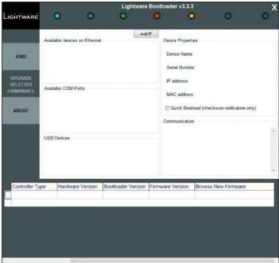
7.1. Upgrading Steps in a Nutshell
Step 1. Installing the Lightware Bootloader Software.
Step 2. Downloading and saving all the firmware files that you want to upgrade.
Step 3. Connecting the Lightware device and the computer via USB port and launch the application.
Step 4. Establishing the connection with the device.
Step 5. Selecting firmware to upgrade.
Step 6. Starting the upgrade process.
Step 7. Restarting the device.
text_image
Lightware Bootloader v3.3.3 LIGHTWARE Add IP Available devices on Ethernet Device Properties Device Name: Serial Number IP address: MAC address: Quick Bootload (checksum verification only) Communication FIND UPGRADE SELECTED FIRMWAREES ABOUT Available COM Ports USB Devices Controller Type Hardware Version Bootloader Version Firmware Version Browse New Firmware


- Firmware Upgrade DVIDL-OPT series - User's Manual 28
7.2. Detailed Instructions
Step 1: Installing the Lightware Bootloader software
Download the application from www.lightware.com, and install it to a Windows-based computer.
Step 2: Downloading and saving all the firmware files that you want to upgrade
Download the firmware from www.lightware.com; if you have a zipped archive, extract it.
Step 3: Connecting the Lightware device and the computer via USB port and launch the application
The extender can only be upgraded via USB. Connect the device directly to the computer by an USB cable.
Step 4: Establishing the connection with the device.
Check the USB Devices panel to find your device. Double click on the name, then click YES to establish connection with the extender. It will take few seconds to get all information from the device. If the connection is established, the device is switched to bootload mode. Front LEDs will show the bootload mode:
- DVIDL-OPT-TX200: The EDID status LED is blinking red and green alternately.
- DVIDL-OPT-RX100: The MONITOR HOTPLUG and LASER DETECT (Link 1) LEDs are blinking alternately.
ATTENTION! The bootloader application will restart the device when it establishes the connection. All connected DVI sources and monitors will act as if the device was powered down.
Switching the Extender to Bootload Mode Manually
If the software is not able to switch the appliance to bootload mode, switch off the extender using the front panel buttons:
- DVIDL-OPT-TX200: remove the DC connector, press and keep the LEARN button pressed, and re-plug the DC connector.
- DVIDL-OPT-RX100: remove the DC connector, press and keep the BOOTLOAD button pressed, and replug the DC connector.
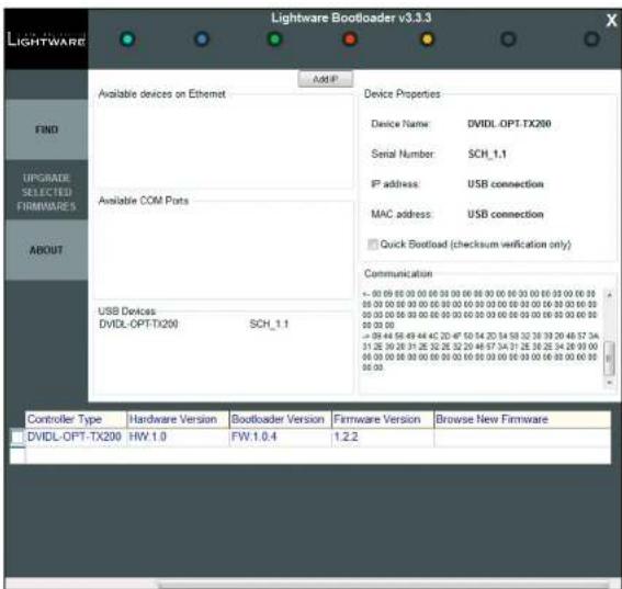
Review the Firmware Versions
After the connection is made, the device properties, and the installed controller module is displayed.
text_image
Lightware Bootloader v3.3.3 LIGHTWARE Add P Device Properties Device Name: DVIDL OPT.TX200 Serial Number: SCH_1.1 IP address: USB connection MAC address: USB connection Quick Bootload (checksum verification only) Communication - 90 69 80 81 82 83 84 85 86 87 88 89 90 91 92 93 94 95 96 97 98 99 00 01 02 03 04 05 06 07 08 09 10 11 12 13 14 15 16 17 18 19 20 21 22 23 24 25 26 27 28 29 30 31 32 33 34 35 36 37 38 39 40 41 42 43 44 45 46 47 48 49 50 51 52 53 54 55 56 57 58 59 60 61 62 63 64 65 66 USB Devices DVIDL OPT.TX200 SCH_1.1 Controller Type Hardware Version Bootloader Version Firmware Version Browse New Firmware DVIDL OPT-TX200 HW.1.0 FW.1.0.4 1.2.2


- Firmware Upgrade DVIDL-OPT series - User's Manual 29
Step 5: Selecting Firmware to Upgrade
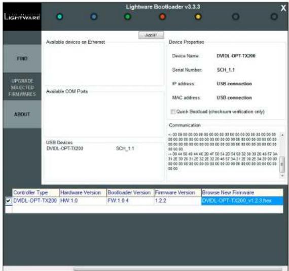
Click the corresponding cell in the Browse New Firmware column. A dialog pops up, to confirm if you really want to modify the path. Now you can browse for the new firmware file to upload. After opening the new file, the new firmware field will contain the name of the firmware file.
text_image
Lightware Bootloader v3.3.3 Device Properties Device Name: DVIDL OPT-TX200 Serial Number: SCH_1.1 IP address: USB connection MAC address: USB connection Quick Bootload (checksum verification only) Communication < 00 09 00 00 00 00 00 00 00 00 00 00 00 00 00 00 00 00 00 00 00 00 00 00 00 00 00 00 00 00 00 00 00 00 00 00 USB Devices DVDL-OPT-TX200 SCH_1.1 Controller Type Hardware Version Bootloader Version Firmware Version Browse New Firmware DVIDL-OPT-TX200 HW 1.0 FW-1.0.4 1.2.2 DVDL-OPT-TX200 -V1.2.3.hexStep 6: Start the Upgrade Process
Press the Upgrade selected firmwares button. A confirmation message appears. After clicking the Yes button the selected controllers are being reprogrammed, with the firmware you selected. If you select a file that does not fit for the selected controller, you will get an information message about which file is wrong. If you selected a controller to upgrade, but you had not selected a file for it, then you will also get an information message about which file is missing.
Quick Bootload mode can be switched on or off any time. It makes the bootloader software faster by only checking the checksum of the controller. No data verification is done after writing if the checksum was correct.
A progress bar will show the current state of the reprogramming. With some controller type an erasing process will take place first, and then the programming is done, so the progress bar runs up twice.
When the reprogramming is finished, a Donel message will appear in the bottom left corner. The application closes the connection, and the device restarts.
Step 7: Done!
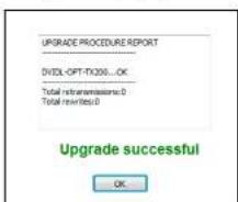
If the upgrade was successful, the following window pops up:
text_image
UPGRADE PROCEDURE REPORT DVIDL-OPT-TX200...OK Total retransmissions: 0 Total retransmissions: 0 Upgrade successful OK...Now you can close the application, or you can select another device to upgrade. After closing the bootloader application, switch the upgraded devices off and then on. Now the extender is ready to be used with the new firmware!

Troubleshooting
Usually, if the system seems not to transport the signal as expected, the best strategy for troubleshooting is to check signal integrity through the whole signal chain starting from source side and moving forward to sink device end.
At first, check front panel LEDs and take the necessary steps according to their states. For more information about status, LEDs refer to the Front View (Transmitter) and Front View (Receiver) sections.
Pictogram Legend
Section to connections/cabling. Section 14 front panel operation.
| Symptom Root cause Action Refer to | |||
| Video/audio signal | |||
| No picture on the output | Device or devices are not powered properly | Check the extender and the other devices if they are properly powered; try to unplug and reconnect them. | 3.5.1 |
| Cable connection problem | Cables must fit very well, check all the connectors. | 3.5 | |
| Optical cable is plugged into incorrect connector (in case of single-link signal) | Check "channel A" and "channel B" optical connections. | 3.5.3 | |
| Wrong type of optical cable is used | Using of Neutrik OpticalCON Duo multimode fiber cable is recommended. | ||
| The surface of the fiber optical cable connector became contaminated | Use special fiber optical cable cleaning equipment to clean it carefully. | ||
| No incoming signal (transmitter) | If the Signal Present LED is not illuminated, no DVI signal is present on the DVI input port. Check the source device and the DVI cable. | 3.5 | |
| No incoming signal (receiver) | If the Signal Present LED is not illuminated, no signal is present on the optical input port. Check the source device and the fiber cable. | 3.5 | |
| Invalid EDID is selected (transmitter) | Check the EDID Status LED. If it is illuminated red, then an invalid EDID or an empty memory address is selected. Select a valid EDID. | 4.3.1 | |
| Data rate is too high for the used type of DVI cable | Select another EDID with lower resolution. | 4.3.1 | |

Technologies
The following sections contain descriptions and useful technical information on the devices work in the background. The content is based on experiences and cases we met in practice. These sections help to understand features and technical standards like the followings:
▶EDID MANAGEMENT
▶PIXEL ACCURATE RECLOCKING
▶DUAL-LINK DVI SIGNAL
9.1. EDID Management
9.1.1. Understanding the EDID
The Extended Display Identification Data (EDID) is the passport of display devices (monitors, TV sets, projectors). It contains information about the capabilities of the display, such as supported resolutions, refresh rates (these are called Detailed Timings), the type and manufacturer of the display device, etc.
After connecting a source to a display (DVI, HDMI, DP), the source reads out the EDID to determine the resolution and refresh rate of the image to be transmitted.
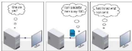
Most DVI computer displays have 128-byte long EDID structure. However, Digital Televisions and HDMI capable displays may have another 128 bytes, which is called E-EDID and defined by CEA (Consumer Electronics Association). This extension contains information about additional Detailed Timings, audio capabilities, speaker allocation and HDMI capabilities. It is important to know that all HDMI capable devices must have CEA extension, but not all devices with CEA extension are HDMI capable.
Common Problems Related to EDID
Problem: "My system consists of the following: a computer, a Lightware device, a WUXGA (1920x1200) LCD monitor, and an SXGA (1280x1024) projector. I would like to see the same image on the monitor and the projector. What EDID should I choose on the Lightware device?"
Solution: If you want to see the image on both displays, you need to select the resolution of the smaller display (in this case SXGA), otherwise the smaller display may not show the higher resolution image.
Problem: "I have changed to a different EDID on an input port of the Lightware device to have a different resolution but nothing happens."
Solution: Some graphics cards and video sources read out the EDID only after power-up and later they do not sense that EDID has been changed. You need to restart your source to make it read out the EDID again.
9.1.2. Advanced EDID Management
Each DVI sink (e.g. monitors, projectors, plasma displays, etc...) must support the EDID data structure. Source BIOS and operating systems are likely to query the sink using DDC2B protocol to determine what pixel formats and interface are supported. DVI standard uses EDID data structure to identify the monitor type and capabilities. Most DVI sources (VGA cards, set top boxes, etc.) will output DVI signal after accepting the connected sink's EDID information. In the case of EDID readout failure or missing EDID, the source will not output DVI video signal.
Lightware devices provide the Advanced EDID Management function that helps system integration. The built-in EDID Router can store and emulate factory pre-programmed- and User programmable EDIDs. The EDID of the attached monitors or projectors for each output are stored in a non-volatile memory. This way the EDID of a monitor is available when the monitor is unplugged or switched off.
Any EDID can be emulated on any input. An emulated EDID can be copied from the EDID router's memory (static EDID emulation), or from the last attached monitor's memory (dynamic EDID emulation). For example, the Lightware device can be set up to emulate a sink device, which is connected to one of the outputs. In this case, the EDID automatically changes, if the monitor is replaced with another display device (as long as it has a valid EDID).
EDID is independently programmable for all inputs without affecting each other. All inputs have their own EDID circuit.
INFO: The user is not required to disconnect the video cable to change an EDID as opposed to other manufacturer's products. EDID can be changed even if a source is connected to the input and powered ON.
INFO: When EDID has been changed, the router toggles the HOTPLUG signal for 2 seconds. Some sources do not sense this signal. In such cases, the source device must be restarted or powered OFF and ON again.
9.2. Pixel Accurate Reclocking
Signal reclocking is an essential important procedure in digital signal transmission. After passing the reclocking circuit, the signal becomes stable, jitter-free, and can be transmitted over more equipment like processors, or event controllers. Without reclocking, sparkles, noise, and jaggies appear on the image.
Lightware's sophisticated Pixel Accurate Reclocking technology fixes more problems than general TMDS reclocking. It removes not only intra-pair skew but inter-pair skew as well. The Pixel Accurate Reclocking circuit eliminates the following errors:
Intra-pair skew
Skew between the + and - wires within a differential wire pair (e.g. Data2- and Data2+). It's caused by different wire lengths or slightly different wire construction (impedance mismatch) in DVI cable. It results in jitter.
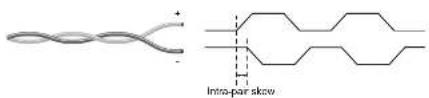
text_image
Intro-pair skewInter-pair skew
Skew between two differential wire pairs in a cable. It is caused by different wire pair lengths or different number of twists in the DVI cable. Too much inter-pair skew results color shift in the picture or sync loss.
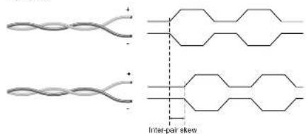
chemical
Diagram showing two molecular structures with inter-pair skew annotationsJitter
Signal instability in the time domain. The time difference between two signal transitions should be a fixed value, but noise and other effects cause variations.
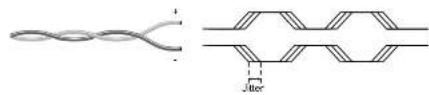
natural_image
Pure electrical circuit lines without any symbolsNoise
Electromagnetic interference between other electronic devices such as mobile phones, motors, etc. and the DVI cable are coupled onto the signal. Too much noise results in increased jitter.

9.3. Dual-Link DVI signal
The Dual-Link DVI interface can operate in either Single-Link or Dual-Link mode. The chosen mode depends on the pixel clock frequency of the signal and it is selected by the hardware automatically. For pixel clock frequencies lower than 165 MHz, Single-Link mode is selected. For higher pixel clock frequencies (up to 330 MHz), Dual-Link mode is selected. It is important to know that pixel clock frequency is not the same as TMDS clock frequency when it comes to Dual-Link DVI.
The pixel clock frequency in Single-Link transmission is a 10th part of the data rate. The maximum data rate of the Single-Link transmission is 1.65 Gbps per TMDS channel and the maximum pixel clock frequency is 165 MHz. In this case the pixel clock frequency equals the TMDS clock frequency. The pixel clock frequency in Dual-Link transmission (when in Dual-Link mode) is a 5th part of the data rate. The maximum data rate of Dual-Link transmission is still 1.65 Gbps per TMDS channel but the maximum pixel clock frequency is 330 MHz. In this case the pixel clock frequency is two times the TMDS clock frequency.
The DVI standard maximizes the data rate of the TMDS channels in 1.65 Gbps. Dual-Link DVI interface enables a higher resolution compared to the Single-Link transmission by doubling the number of wire pairs to transmit the video signal. In Single-Link cables 3 wire pairs carry the color information (red, green and blue) and one wire pair carries the clock signal (TMDS clock).
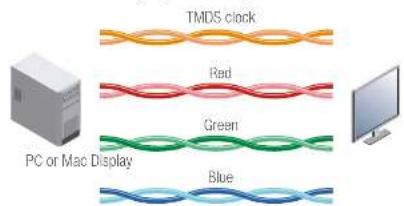
text_image
TMDS clock Red Green PC or Mac Display BlueVideo lines of the Single-Link interface


- Technologies DVIDL-OPT series - User's Manual 33
In Dual-Link cables, 6 wire pairs carry the color information next to the TMDS clock signal. One color component is carried by two wire pairs, where one wire pair carries the odd pixels and the other wire pair carries the even pixels.
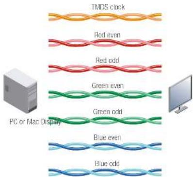
text_image
TMDS clock Red even Red odd Green even Green odd Blue even Blue odd PC or Mac DisplayVideo lines of the Dual-Link interface
INFO: The colors of the wire pairs in the picture represent the color information they carry and not the color of the actual wires inside the cable.
10
Appendix
▶ SPECIFICATIONS
▶MAXIMUM FIBER CABLE EXTENSIONS
▶MECHANICAL DRAWINGS
▶FACTORY EDID LIST
▶FURTHER INFORMATION
10.1. Specifications
General
Compliance......CE
EMC (Emission) EN 55032:2015
EMC (Immunity)....EN 55035:2017
Safety....EN 60065 Class II
Warranty 3 years
Cooling....Passive
Operating temperature 0 to +50°C (+32 to +122°F)
Operating humidity 10% to 90%, non-condensing
Power
Power supply....External power adaptor
Power adaptor.....In 100-240 V AC 50/60 Hz, Out 5V DC, 2.5 A
Power connector....Locking DC connector (2.35 mm pin)
Power consumption (TX) 3.5 W*
Power consumption (RX) 4 W *
* Self-consumption; remote powering not included.
Enclosure
Rack mountable....Yes, with rack shelf (1U high)
Material....1 mm steel
Dimensions in mm....110 W x 181 D x 42.2 H (excluding connectors)
Dimensions in inch 4.72 W x 7.08 D x 1.65 H
Weight (TX) 726 g (1.601 lbs)
Weight (RX) 721 g (1.589 lbs)
Video Ports
Connector type....29-pole, DVI-I
Standard DVI 1.0
Color depth...... maximum 24 bits, 8 bit/color
Color format....RGB
Colorspace conversion....No
Maximum data rates....9.9 Gbps (1.65 Gbps /TMDS channel)
Video delay 0 frame
Resolution up to 4096x2400
Reclocking (RX)....TMDS Reclocking
EDID emulation (TX) .... yes, Advanced EDID Management
EDID memory (TX).....yes, 60 factory preset, 39 user programmable
EDID support (TX) 256 byte extended EDID v1.3
HDCP compliant.... No
Optical Ports
Connector type......Neutrik NO2-4FDW type LC duplex
Fiber type.... 50/125 SC Multimade fiber
Laser wavelengths.....4 channel CWDM: 778; 800; 825; 850 nm
Laser class specification.... Class 3R
Transmitter output OMA * -6.25 dBm (worst case)
Receiver OMA * sensitivity....-14.25 dBm (worst case)
Optical loss budget....8 dBm (worst case)
Transmission distance.... 2500 meters (using OM3e type fiber)
* OMA: Optical Modulation Amplitude
Connectors / ESD protection (HBM EIA/JESD22-A114F)
DVI input/output..... 29-pole DVI-I digital only / 8 kV
Optical fiber input/output..... Neutrik NO2-4FDW type LC duplex / n.a.
USB port ....USB 2.0, Mini B type / n.a.
Power connector..... Locking DC connector (2.35 mm pin) / 2 kV
10.2. Maximum Fiber Cable Extensions
| OM1 OM2 OM3 OM4 | ||||
| (62.5/125) | (50/125) | (50/125) | (50/125) | |
| 1080p@60Hz24 bpp | 250 m | 600 m | 1200 m | 2500 m |
| 1080p@60Hz36 bpp | 150 m | 400 m | 800 m | 1300 m |
| 4096x2048@30Hz24 bpp | Not supported | 350 m | 700 m | 1100 m |
10.3. Mechanical Drawings
TX200 can be seen in the pictures but the dimensions are the same for both models. Dimensions are in mm
Front View Rear View
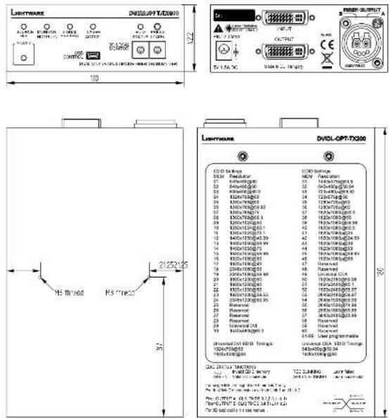
Bottom View Top View
10.4. Factory EDID List
| Mem. | Resolution | Type | |||
| F1 | 640 x | 480p | @ 60.0 | Hz | D |
| F2 | 848 x | 480p | @ 60.0 | Hz | D |
| F3 | 800 x | 600p | @ 60.30 | Hz | D |
| F4 | 1024 x | 768p | @ 60.0 | Hz | D |
| F5 | 1280 x | 768p | @ 50.0 | Hz | D |
| F6 | 1280 x | 768p | @ 59.92 | Hz | D |
| F7 | 1280 x | 768p | @ 75.0 | Hz | D |
| F8 | 1360 x | 768p | @ 60.1 | Hz | D |
| F9 | 1280 x | 1024p | @ 50.0 | Hz | D |
| F10 | 1280 x | 1024p | @ 60.1 | Hz | D |
| F11 | 1280 x | 1024p | @ 75.1 | Hz | D |
| F12 | 1400 x | 1050p | @ 49.99 | Hz | D |
| F13 | 1400 x | 1050p | @ 59.99 | Hz | D |
| F14 | 1400 x | 1050p | @ 75.0 | Hz | D |
| F15 | 1680 x | 1050p | @ 59.99 | Hz | D |
| F16 | 1920 x | 1080p | @ 50.0 | Hz | D |
| F17 | 1920 x | 1080p | @ 60.0 | Hz | D |
| F18 | 2048 x | 1080p | @ 50.0 | Hz | D |
| F19 | 2048 x | 1080p | @ 59.99 | Hz | D |
| F20 | 1600 x | 1200p | @ 50.0 | Hz | D |
| F21 | 1600 x | 1200p | @ 60.0 | Hz | D |
| F22 | 1920 x | 1200p | @ 50.0 | Hz | D |
| F23 | 1920 x | 1200p | @ 59.55 | Hz | D |
| F24 | 2048 x | 1200p | @ 59.95 | Hz | D |
| F29 | Universal DVI EDID | U | |||
| F30 | 1440 x | 480i | @ 60.3 | Hz | C |
| F31 | 1440 x | 576i | @ 50.6 | Hz | C |
| F32 | 640 x | 480p | @ 59.94 | Hz | C |
| F33 | 720 x | 480p | @ 59.92 | Hz | C |
| F34 | 720 x | 576p | @ 50.0 | Hz | C |
| Mem. | Resolution | Type | |||
| F35 | 1280 x | 720p | @ 50.0 | Hz | C |
| F36 | 1280 x | 720p | @ 60.0 | Hz | C |
| F37 | 1920 x | 1080i | @ 50.3 | Hz | C |
| F38 | 1920 x | 1080i | @ 50.0 | Hz | C |
| F39 | 1920 x | 1080i | @ 59.98 | Hz | C |
| F40 | 1920 x | 1080i | @ 60.5 | Hz | C |
| F41 | 1920 x | 1080p | @ 24.0 | Hz | C |
| F42 | 1920 x | 1080p | @ 24.99 | Hz | C |
| F43 | 1920 x | 1080p | @ 30.0 | Hz | C |
| F44 | 1920 x | 1080p | @ 50.0 | Hz | C |
| F45 | 1920 x | 1080p | @ 59.93 | Hz | C |
| F46 | 1920 x | 1080p | @ 60.0 | Hz | C |
| F49 | Universal EDID with CEA | U | |||
| F50 | 1920 x | 2160p | @ 59.98 | Hz | D |
| F51 | 1024 x | 2400 | @ 60.1 | Hz | D |
| F52 | 1920 x | 2400 | @ 59.97 | Hz | D |
| F53 | 2048 x | 2400 | @ 59.97 | Hz | D |
| F54 | 2048 x | 1536 | @ 59.99 | Hz | D |
| F55 | 2048 x | 1536 | @ 74.99 | Hz | D |
| F56 | 2560 x | 1600 | @ 59.85 | Hz | D |
| F57 | 3840 x | 2400 | @ 23.99 | Hz | D |
Legend
D: DVI EDID
C: EDID with CEA extension
U: Universal EDID (supporting many common resolutions)
Please note that minor changes in the factory EDID list may be applied in later firmware versions.


- Appendix DVIDL-OPT series – User's Manual 36
10.5. Further Information
Limited Warranty Statement
- Lightware Visual Engineering LLC (Lightware) warrants to all trade and end user customers that any Lightware product purchased will be free from manufacturing defects in both material and workmanship for three (3) years from purchase unless stated otherwise below. The warranty period will begin on the latest possible date where proof of purchase/delivery can be provided by the customer. In the event that no proof can be provided (empty 'Date of purchase' field or a copy of invoice), the warranty period will begin from the point of delivery from Lightware.
1.1. 25G and MODEX product series will be subject to a seven (7) year warranty period under the same terms as outlined in this document.
1.2. If during the first three (3) months of purchase, the customer is unhappy with any aspect of a Lightware product, Lightware will accept a return for full credit.
1.3. Any product that fails in the first six (6) months of the warranty period will automatically be eligible for replacement and advanced replacement where available. Any replacements provided will be warranted for the remainder of the original unit's warranty period.
1.4. Product failures from six (6) months to the end of the warranty period will either be repaired or replaced at the discretion of Lightware. If Lightware chooses to replace the product then the replacement will be warranted for the remainder of the original unit's warranty period.
- The above-stated warranty and procedures will not apply to any product that has been:
2.1. Modified, repaired or altered by anyone other than a certified Lightware engineer unless expressly agreed beforehand.
2.2. Used in any application other than that for which it was intended.
2.3. Subjected to any mechanical or electrical abuse or accidental damage.
2.4. Any costs incurred for repair/replacement of goods that fall into the above categories (2.1., 2.2., 2.3.) will be borne by the customer at a pre-agreed figure.
- All products to be returned to Lightware require a return material authorization number (RMA) prior to shipment and this number must be clearly marked on the box. If an RMA number is not obtained or is not clearly marked on the box, Lightware will refuse the shipment.
3.1. The customer will be responsible for in-bound and Lightware will be responsible for out-bound shipping costs.
3.2. Newly repaired or replaced products will be warranted to the end of the originally purchased products warranty period.
Document Revision History
| Rev. | Release date | Changes Editor | |
| 1.0 03 | -07-2014 Initial version Laszlo | Zsedenyi | |
| 1.1 15 | -12-2015 Safety instructions updated, CE page pulled out | Laszlo Zsedenyi | |
| 2.0 06 | -04-2017 Minor updates to Software Control (LDC) chapter, updated Troubleshooting chapter | Tamas Forgacs | |
| 3.0 30 | -08-2018 New document format introduced, LDC chapter upgraded | Laszlo Zsedenyi |
Contact Us
sales@lightware.com
+36 1 255 3800
support@lightware.com
+36 1 255 3810
Lightware Visual Engineering LLC.
Peterdy 15, Budapest H-1071, Hungary
www.lightware.com
©2018 Lightware Visual Engineering. All rights reserved. All trademarks mentioned are the property of their respective owners. Specifications subject to change without notice.