GTV-WHD-60G - Audio/video extender Gefen - Free user manual and instructions
Find the device manual for free GTV-WHD-60G Gefen in PDF.


User questions about GTV-WHD-60G Gefen
0 question about this device. Answer the ones you know or ask your own.
Ask a new question about this device
Download the instructions for your Audio/video extender in PDF format for free! Find your manual GTV-WHD-60G - Gefen and take your electronic device back in hand. On this page are published all the documents necessary for the use of your device. GTV-WHD-60G by Gefen.
USER MANUAL GTV-WHD-60G Gefen
Wireless Extender for HDMI 60 GHz
GTV-WHD-60G
User Manual
Release A2
text_image
GefenV Wireless for HDMI 60 GHz S GefenV Wireless for HDMI 60 GHz RImportant Safety Instructions
GENERAL SAFETY INFORMATION
- Read these instructions.
- Keep these instructions.
- Heed all warnings.
- Follow all instructions.
- Do not use this product near water.
-
Clean only with a dry cloth.
-
Do not block any ventilation openings. Install in accordance with the manufacturer's instructions.
-
Do not install or place this product near any heat sources such as radiators, heat registers, stoves, or other apparatus (including amplifiers) that produce heat.
-
Do not defeat the safety purpose of the polarized or grounding-type plug. A polarized plug has two blades with one wider than the other. A grounding type plug has two blades and a third grounding prong. The wide blade or the third prong are provided for your safety. If the provided plug does not fit into your outlet, consult an electrician for replacement of the obsolete outlet.
-
Protect the power cord from being walked on or pinched particularly at plugs, convenience receptacles, and the point where they exit from the apparatus.
-
Only use attachments/accessories specified by the manufacturer.
-
To reduce the risk of electric shock and/or damage to this product, never handle or touch this unit or power cord if your hands are wet or damp. Do not expose this product to rain or moisture.
-
Unplug this apparatus during lightning storms or when unused for long periods of time.
-
Refer all servicing to qualified service personnel. Servicing is required when the apparatus has been damaged in any way, such as power-supply cord or plug is damaged, liquid has been spilled or objects have fallen into the apparatus, the apparatus has been exposed to rain or moisture, does not operate normally, or has been dropped.
-
Batteries that may be included with this product and/or accessories should never be exposed to open flame or excessive heat. Always dispose of used batteries according to the instructions.
Warranty Information
Gefen warrants the equipment it manufactures to be free from defects in material and workmanship.
If equipment fails because of such defects and Gefen is notified within two (2) years from the date of shipment, Gefen will, at its option, repair or replace the equipment, provided that the equipment has not been subjected to mechanical, electrical, or other abuse or modifications. Equipment that fails under conditions other than those covered will be repaired at the current price of parts and labor in effect at the time of repair. Such repairs are warranted for ninety (90) days from the day of reshipment to the Buyer.
This warranty is in lieu of all other warranties expressed or implied, including without limitation, any implied warranty or merchantability or fitness for any particular purpose, all of which are expressly disclaimed.
- Proof of sale may be required in order to claim warranty.
- Customers outside the US are responsible for shipping charges to and from Gefen.
- Copper cables are limited to a 30 day warranty and cables must be in their original condition.
The information in this manual has been carefully checked and is believed to be accurate. However, Gefen assumes no responsibility for any inaccuracies that may be contained in this manual. In no event will Gefen be liable for direct, indirect, special, incidental, or consequential damages resulting from any defect or omission in this manual, even if advised of the possibility of such damages. The technical information contained herein regarding the features and specifications is subject to change without notice.
For the latest warranty coverage information, refer to the Warranty and Return Policy under the Support section of the Gefen Web site at www.gefen.com.
PRODUCT REGISTRATION
Please register your product online by visiting the Register Product page under the Support section of the Gefen Web site.
Contacting Gefen Technical Support
Gefen, LLC
c/o Customer Service
20600 Nordhoff St.
Chatsworth, CA 91311
Telephone: (818) 772-9100
(800) 545-6900
Fax: (818) 772-9120
Email: support@gefentv.com
Visit us on the Web: www.gefentv.com
Technical Support Hours: 8:00 AM to 5:00 PM Monday - Friday, Pacific Time
Wireless for HDMI 60 GHz is a trademark of Gefen, LLC.
Important Notice
Gefen, LLC reserves the right to make changes in the hardware, packaging, and any accompanying documentation without prior written notice.
Operating Notes
- Pairing is not required when a Sender and Receiver unit are purchased as a pair. However, if either a Sender and Receiver unit is purchased separately, then the units will require pairing.
- The distance between the Sender and Receiver unit should not exceed 33 feet (10 meters).
- This product will not transmit through walls. The Sender and Receiver unit must be used in the same room.
- The Wireless for HDMI 60 GHz must be used with HDCP compliant HDMI displays.
CE①
This radio equipment may only be operated indoors. Operation outdoors is in violation of 47 U.S.C.301 and could subject the operator to serious legal penalties.

Federal Communication Commission Interference Statement
- This device complies with Part 15 of the FCC Rules. Operation is subject to the following two conditions: (1) this device may not cause harmful interference, and (2) this device must accept any interference received, including interference that may cause undesired operation.
- NOTE: This equipment has been tested and found to comply with the limits for a Class B digital device, pursuant to Part 15 of the FCC Rules. These limits are designed to provide reasonable protection against harmful interference in a residential installation. This equipment generates, uses, and can radiate radio frequency energy and, if not installed and used in accordance with the instructions, may cause harmful interference to radio communications.
- In order to comply with FCC RF Exposure requirements, a separation distance of at least 20 cm must be maintained between the antenna and all persons. However, there is no guarantee that interference will not occur in a particular installation. If this equipment does cause harmful interference to radio or television reception, which can be determined by turning the equipment off and on, the user is encouraged to try to correct the interference by one or more of the following measures:
Operating Notes
- Reorient or relocate the device(s) causing the interference.
- Increase the separation between the devices.
- Connect equipment into an outlet on a circuit different from that to which the device experiencing interference is connected.
- Consult the dealer or an experienced radio/TV technician for help.
Features and Packing List
Features
- Wireless extension of HDMI up to 33 feet (10 meters)
• Supports resolutions up to 1080p Full HD
• HDMI Features Supported
▶ HDCP pass-through
▶ 3DTV pass-through
▶ CEC pass-through
▶ Dolby® TrueHD, DTS-HD Master Audio™, and LPCM digital audio streams up to 7.1 channels
▶ Lip Sync
- Uncompressed High Definition A/V from source to display
• Near-zero latency (less than one frame) - Specifically designed for in-room operation only.
- Operates in the uncluttered 60GHz frequency region, minimizing the chances of interference from household devices such as cordless phones or WiFi equipment
• Field upgradable via USB port

HDMI®
HIGH-DEFINITION MULTIMEDIA INTERFACE
1080P
PROGRESSIVE
HDCP
COMPLIANT
Packing List
The Wireless for HDMI 60 GHz ships with the items listed below. If any of these items are not present in your box when you first open it, immediately contact your dealer or Gefen.
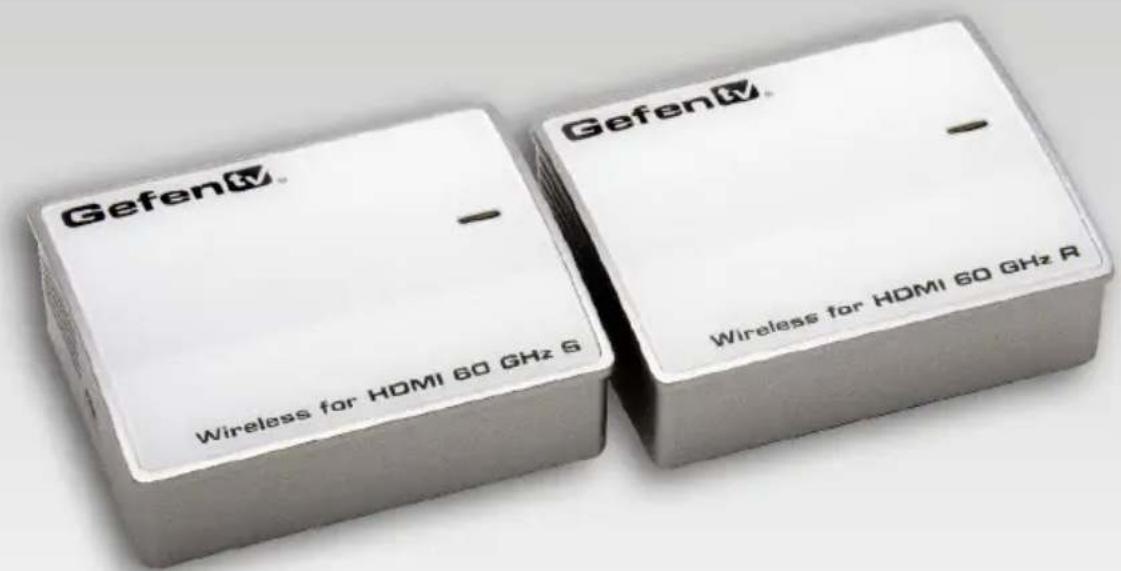
• 1 x Wireless for HDMI 60 GHz (Sender)
• 1 x Wireless for HDMI 60 GHz (Receiver)
• 2 x HDMI cables (M-M)
- 2 x 5V DC power supplies
• 1 x Quick-Start Guide
Table of Contents
01 Getting Started
Panel Layout 2
Sender unit....2
Receiver unit 3
Installation 4
Connecting the Wireless for HDMI 60 GHz....4
Sample Wiring Diagram 5
02 Operating the Wireless for HDMI 60 GHz
The Sender / Receiver Pair....8
Using Multiple Units....9
Placement 9
Pairing....11
Pairing a Sender and Receiver unit 11
Pairing multiple Sender units to a Receiver unit 11
Performing a Factory-Reset.... 11
03 Appendix
Supported Video and Audio Formats 14
Firmware Upgrade Procedure.... 16
Installing the Software.... 16
Upgrading the Firmware.... 17
Specifications 21
Wireless Extender for HDMI 60 GHz
01 Getting Started
Panel Layout 2
Sender unit....2
Receiver unit 3
Installation 4
Connecting the Wireless for HDMI 60 GHz....4
Sample Wiring Diagram 5
Panel Layout
Sender unit

ID Name Description
| 1 Service This port is for factory use only. | |
| 2 Power indicator This LED indicator will glow | solid blue or flash, depending upon the status of the Sender unit. See The Sender / Receiver Pair for more information. |
| 3 Pair Used to pair a Sender with a Receiver. | See Pairing for more information. |
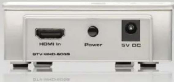
| 4 HDMI In Connect an HDMI cable from the Hi-Def source to this connector. | |
| 5 Power Press this button to toggle power on the Sender unit. | |
| 6 5V DC Connect the included 5V DC power supply to this power receptacle. | |
Receiver unit
text_image
Gefen tv Wireless for HDMI 60 GHz R 1 2 3 4 5 HDMI Out Power 5V DC GTV-WHD-8DDRID Name Description
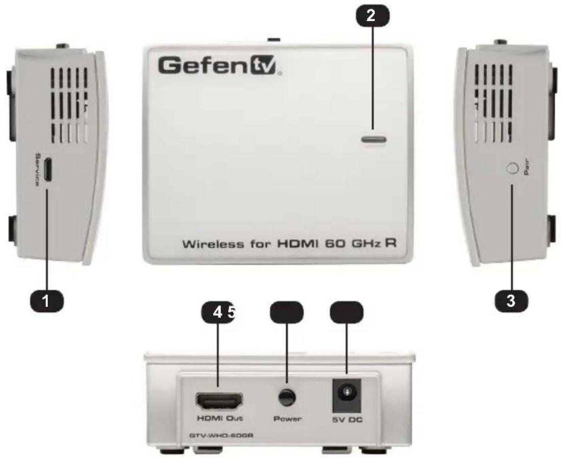
| 1 Service This port is for factory use only. | |
| 2 Power indicator This LED indicator will glow | solid blue or flash, depending upon the status of the Sender unit. See The Sender / Receiver Pair for more information. |
| 3 Pair Used to pair a Receiver with a Sender. | See Pairing for more information. |
| 4 HDMI Out Connect an HDMI cable from this connector to the HDTV display. | |
| 5 Power Press this button to toggle power on the Receiver unit. | |
| 6 5V DC Connect the included 5V DC power supply to this power receptacle. | |
Connecting the Wireless for HDMI 60 GHz
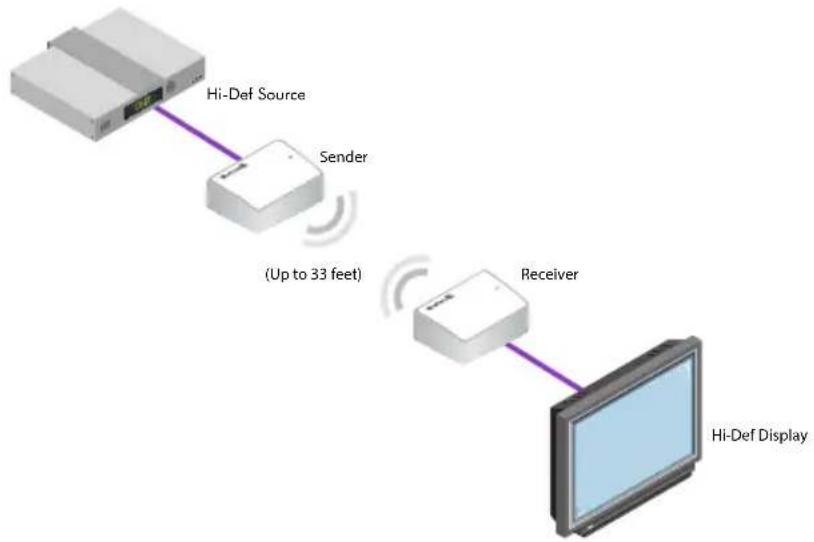
- Connect an HDMI cable from the Hi-Def source to the HDMI In connector on the Sender unit.
- Connect an HDMI cable from the HDMI Out connector to an HDCP compliant HDTV display (or other sink device).
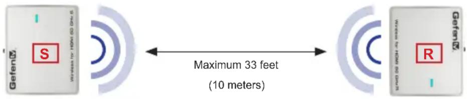
- Position both the Sender and Receiver unit so that they are facing one another, as shown below.
The distance between the Sender and Receiver unit should not exceed 33 feet (10 meters). This product will not transmit through walls.
text_image
GefenX S Maximum 33 feet (10 meters) GefenX R- Connect each of the included power supplies to the 5V DC power receptacle on the Sender and Receiver unit.
- Connect both power supplies to available electrical outlets.
- Power-on both the Sender and Receiver units by pressing the Power button on the back panel.
Sample Wiring Diagram
Gefen tv
HDMI CABLE

flowchart
graph LR
    A["Wi-Fi Device"] -->|Hi-Def Source| B["Sender"]
    B --> C["(Up to 33 feet)"]
    C --> D["Receiver"]
    D --> E["Hi-Def Display"]
GTV-WHD-60G
Wireless Extender for HDMI 60 GHz
02 Operating the Wireless for HDMI 60 GHz
The Sender / Receiver Pair 8
Using Multiple Units....9
Placement 9
Pairing....11
Pairing a Sender and Receiver unit 11
Pairing multiple Sender units to a Receiver unit 11
Performing a Factory-Reset 11
The Sender / Receiver Pair
Once a solid audio / video connection has been established by both the Sender and Receiver unit of the Wireless for HDMI 60 GHz, the Power LED indicator on the top of the Sender and Receiver unit should glow bright blue. The LED indicator should not blink under normal operating conditions.

flowchart
graph TD
    A["Power LED indicators"] --> B["Gefen®"]
    B --> C["Receiver unit"]
    C --> D["HDTV display to Hi-Def source"]
    style A fill:#f9f,stroke:#333
    style B fill:#ccf,stroke:#333
    style C fill:#cfc,stroke:#333
    style D fill:#fcc,stroke:#333
    note1["Sender unit"] <--> note2["Maximum 33 feet (10 meters)"]
    note3["Power LED indicators"] --> A
Table 2.1 - Power LED indicator status
| Status Conditions | |
| Solid blue • The signal integrity between the Sender and Receiver unit is good. | |
| Off • The units are in sleep mode.• The Sender unit is not powered.• The Receiver unit is not powered. | |
Flashing slowly  | • Either the associated (paired) Sender or Receiver unit is not powered on or the units are not paired. |
Flashing quickly  | • The units are paired together but either the Sender unit is not connected to a source or the Receiver unit is not connected to a display or other sink device. |
Using Multiple Units
Placement
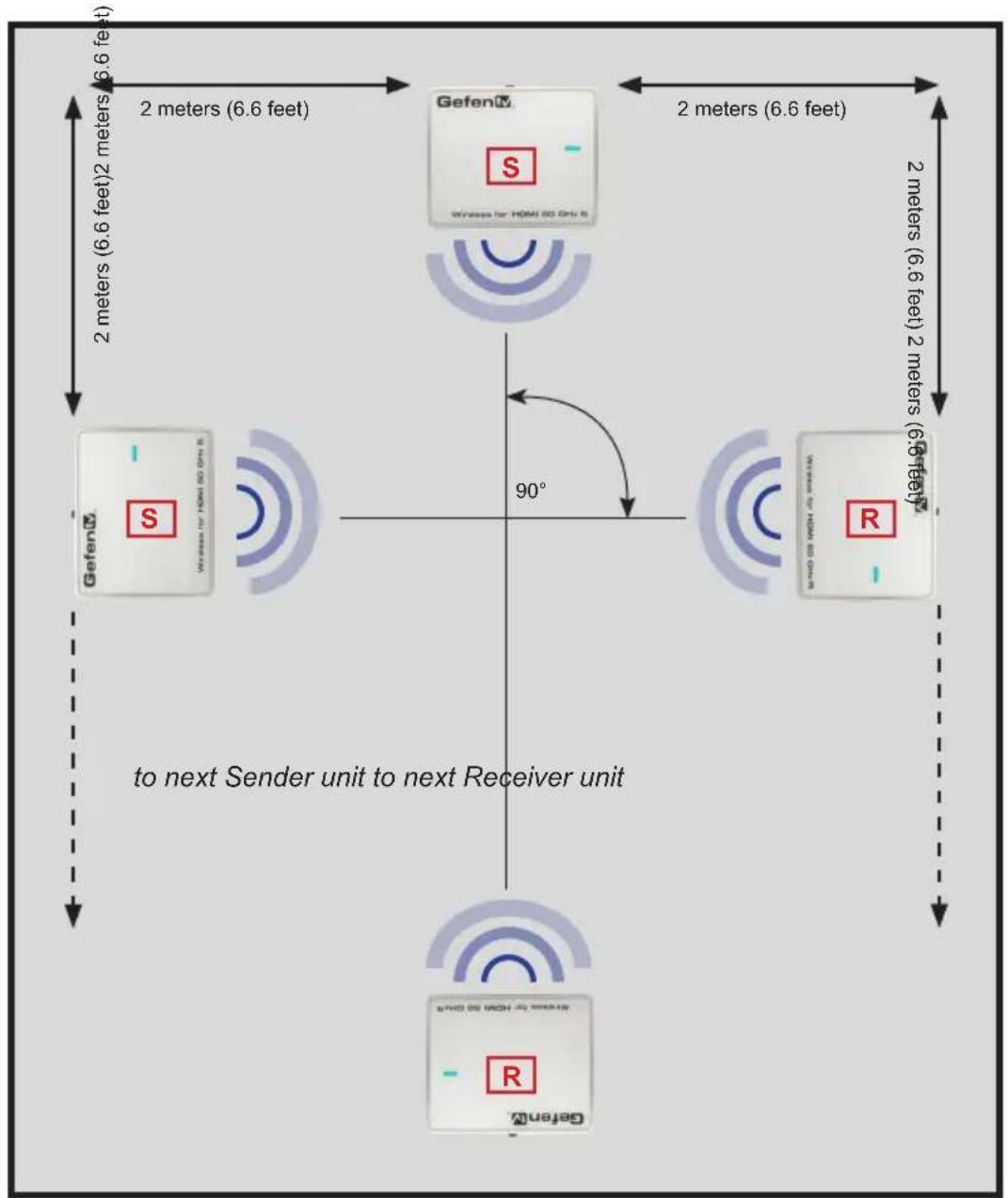
Up to 5 Sender-Receiver pairs can be used within a room. When using two or more Sender-Receiver pairs in a room, the following requirements must be met.
• Each Sender and Receiver unit must be at least 2 meters apart.
• Each pair of Sender and Receiver units should face one another.
• To minimize the possibility of crosstalk, additional Sender-Receiver pairs should be set perpendicular to one another. See Figure 2.1.
Figure 2.1 - Positioning multiple Sender-Receiver pairs in a room
flowchart
graph TD
    A["To the next Sender unit"] --> B["GefenX"]
    B --> C["R"]
    C --> D["GefenX"]
    D --> E["To the second Sender unit"]
    E --> F["Next Receiver Unit"]
    F --> G["GefenX"]
    G --> H["R"]
    H --> I["GefenX"]
    I --> J["To the second Sender unit"]
    J --> K["GefenX"]
    K --> L["To the second Sender unit"]
    L --> M["GefenX"]
    M --> N["GefenX"]
    style A fill:#f9f,stroke:#333
    style B fill:#ccf,stroke:#333
    style C fill:#ccf,stroke:#333
    style D fill:#ccf,stroke:#333
    style E fill:#ccf,stroke:#333
    style F fill:#ccf,stroke:#333
    style G fill:#ccf,stroke:#333
    style H fill:#ccf,stroke:#333
    style I fill:#ccf,stroke:#333
    style J fill:#ccf,stroke:#333
    style K fill:#ccf,stroke:#333
    style L fill:#ccf,stroke:#333
    style M fill:#ccf,stroke:#333
(continued on next page)
Using Multiple Units
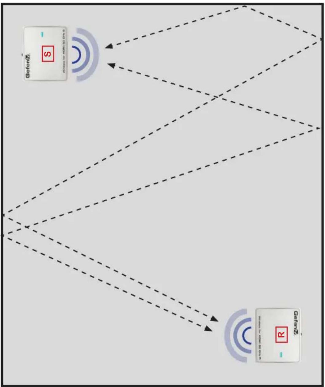
- If the Sender-Receiver pair is not facing one another, then it is important that walls are present in the operating environment. The walls will act as a waveguide and allow the radio waves to be communicated between the Sender and Receiver unit. See figure 2.2, below.
Figure 2.2 - Walls guide the radio waves between the Sender and Receiver unit.
flowchart
graph TD
    A["Gefen2 Card"] -->|Signal| B["Wireless Interface"]
    B --> C["Wireless Interface"]
    C --> D["Wireless Interface"]
    D --> E["Wireless Interface"]
    E --> F["Wireless Interface"]
    F --> G["Wireless Interface"]
    G --> H["Wireless Interface"]
    H --> I["Wireless Interface"]
    I --> J["Wireless Interface"]
    J --> K["Wireless Interface"]
    K --> L["Wireless Interface"]
    L --> M["Wireless Interface"]
    M --> N["Wireless Interface"]
    N --> O["Wireless Interface"]
    O --> P["Wireless Interface"]
    P --> Q["Wireless Interface"]
    Q --> R["Wireless Interface"]
    R --> S["Wireless Interface"]
    S --> T["Wireless Interface"]
    T --> U["Wireless Interface"]
    U --> V["Wireless Interface"]
    V --> W["Wireless Interface"]
    W --> X["Wireless Interface"]
    X --> Y["Wireless Interface"]
    Y --> Z["Wireless Interface"]
Pairing
When the Sender and Receiver units are purchased together, pairing is not required. However, if either a Sender or Receiver unit is purchased separately, then the units will require pairing.
Pairing a Sender and Receiver unit

IMPORTANT: If more than one Sender-Receiver pair is being used in the room, make sure to power-down all other Sender-Receiver pairs before continuing with the pairing process. If this is not possible, the pairing process must be performed in a separate room.
- Disconnect the HDMI cable and power cable from the unit that is being replaced.
- Connect the new Sender or Receiver unit to the HDMI cable and power supply.
- Power-on the new unit by pressing the Power button on the back panel.
- The Power LED will begin to flash.
- Press and release the Pair button on either the Sender or Receiver unit. After a few moments, the Sender-Receiver pair will resume communication.
- If for some reason the Sender and Receiver unit do not pair with one another, repeat step 5.
Pairing multiple Sender units to a Receiver unit
It is possible to use two Sender units with a single Receiver unit, allowing switching between two Hi-Def sources. Each Sender unit must first be individually paired with the Receiver unit. Prior to performing this task, confirm that other Sender units, within the same room, are powered-off to avoid any potential conflicts.
Once both Sender units are paired to a single Receiver, push the Pair button on the Receiver unit to switch between each Sender unit.
Performing a Factory-Reset
In order to perform a factory-reset of the Wireless Extender for HDMI 60 GHz, press and hold the Pair button on the Sender unit for 10 seconds. Repeat the process for the Receiver unit. The order in which the Sender and Receiver are reset does not matter.
Wireless Extender for HDMI 60 GHz
03 Appendix
Supported Video and Audio Formats 14
Firmware Upgrade Procedure 16
Installing the Software.... 16
Upgrading the Firmware.... 17
Specifications 21
Supported Video and Audio Formats
Table 3.1 - Supported Video Formats
| Resolution Timing (Hz) Color Space Sampling Bits / Pixel | ||||
| 480i 59.94 / 60 YCbCr 4:2:2 24 / 30 | ||||
| 4:4:4 | ||||
| RGB 4:4:4 | ||||
| 480p 59.94 / 60 YCbCr 4:2:2 24 / 30 | ||||
| 4:4:4 | ||||
| RGB 4:4:4 | ||||
| 576i 50 YCbCr 4:2:2 24 / 30 | ||||
| 4:4:4 | ||||
| RGB 4:4:4 | ||||
| 576p 50 YCbCr 4:2:2 24 / 30 | ||||
| 4:4:4 | ||||
| RGB 4:4:4 | ||||
| 720p 50 YCbCr 4:2:2 24 / 30 | ||||
| 4:4:4 | ||||
| RGB 4:4:4 | ||||
| 59.94 / 60 YCbCr 4:2:2 | ||||
| 4:4:4 | ||||
| RGB 4:4:4 | ||||
| 1080i 50 YCbCr 4:2:2 24 / 30 | ||||
| 4:4:4 | ||||
| RGB 4:4:4 | ||||
| 59.94 / 60 YCbCr 4:4:4 | ||||
| 4:2:2 | ||||
| RGB 4:4:4 | ||||
| 1080p 23.976 / 24 YCbCr 4:2:2 24 / 30 | ||||
| 4:4:4 | ||||
| RGB 4:4:4 | ||||
| 50 YCbCr 4:2:2 | ||||
| 4:4:4 24 | ||||
| RGB 4:4:4 24 / 30 | ||||
| 59.94 / 60 YCbCr 4:2:2 | ||||
| 4:4:4 24 | ||||
| RGB 4:4:4 24 / 30 | ||||
| Resolution Timing (Hz) Color Space Sampling Bits / Pixel | |||
| VGA 60 RGB 4:4:4 24 / 30 | |||
| WVGA | |||
| SVGA | |||
| XGA | |||
| SXGA | |||
| WSXGA+ | |||
Table 3.2 - Supported 3D Formats
| Type Resolution Timing (Hz) | ||
| Frame Packing 1080p 23.98 / 24 | ||
| 720p 50 / 59.94 / 60 | ||
| Top - Bottom 1080p 23.98 / 24 | ||
| 720p 50 / 59.94 / 60 | ||
| Side-by-Side 1080i | 50 / 59.94 / 60 | |
Table 3.3 - Supported Audio Formats
| Type Sampling Rates (kHz) | |
| DTS® | 32 |
| Dolby® Digital | 44.1 |
| Dolby® TrueHD | |
| DTS-HD Master AudioTM | 48 |
| LPCM 2 / 6 / 8-channel | 32 |
| 44.1 | |
| 48 | |
| 88.2 | |
| 96 | |
| LPCM 2-channel | 176.4 |
| 192 | |
Firmware Upgrade Procedure
The following items are required to update firmware:
• GefenTV Wireless for HDMI 60 GHz (Sender and Receiver unit)
- PC-compatible computer running Windows®
• USB-to-Micro USB cable
- Installation software
- Firmware files
Installing the Software
- Download the installation software and firmware files from the Gefen Web site.
- Extract the files from the .ZIP file to the desired folder.
- Locate the M3RTUpgradeInstaller.msi file.
- Right-click on the file and select Run as administrator from the context menu.
If the computer is already setup with administrator privileges, then simply select Install from the context menu (or double-click the file).
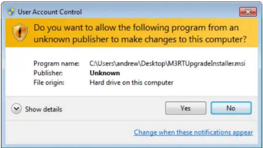
- During the installation process, the following dialog will be displayed:
text_image
User Account Control Do you want to allow the following program from an unknown publisher to make changes to this computer? Program name: C:\Users\andrew\Desktop\M3RTUpgradeInstaller.msi Publisher: Unknown File origin: Hard drive on this computer Show details Yes No Change when these notifications appear- Click the Yes button to allow the installation process to continue.
- Follow the directions on each screen of the installation Wizard.
- Once the installation process is complete, click the Finish button to exit the installer.
Upgrading the Firmware
- Connect a USB-to-Micro USB cable between the computer and the Receiver unit. Make sure that the Sender unit is powered.

NOTE: The order in which the Sender and Receiver unit is upgraded does not matter. We are arbitrarily beginning with the Receiver unit.
Once the USB cable has been connected, the following message will be displayed near the bottom of the screen. The COM port may be different on each computer.

SIMG SB92xx Host Serial (COM10)
Device driver software installed successfully.

- Right-click on the M3RT_Upgrade icon and select Run as administrator.

MBRT_Upg...
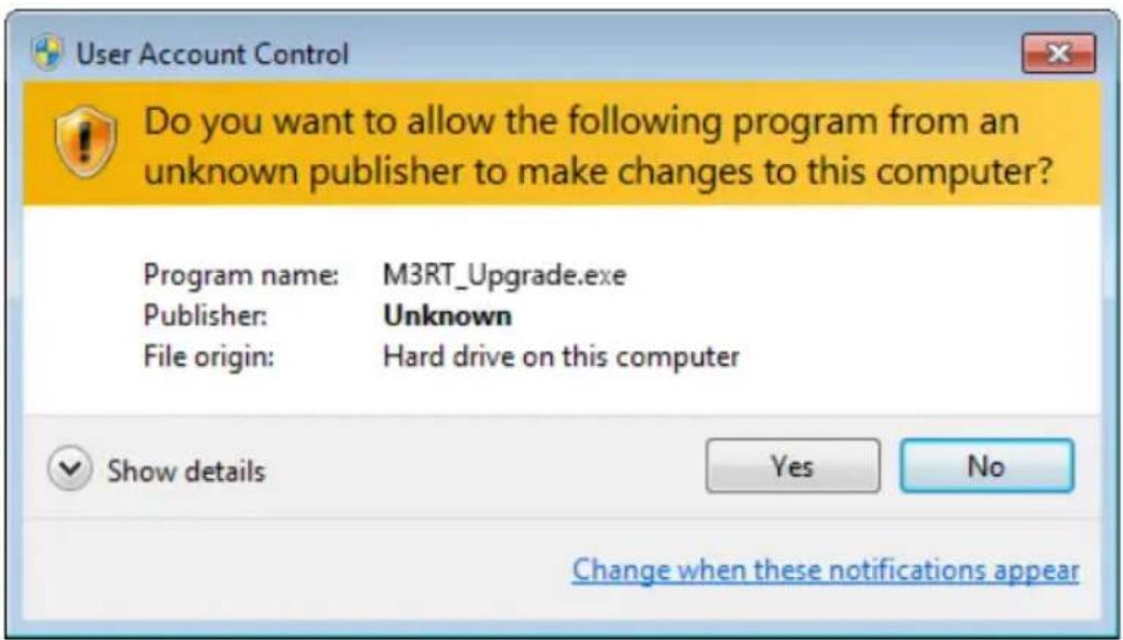
- The following dialog will be displayed:
text_image
User Account Control Do you want to allow the following program from an unknown publisher to make changes to this computer? Program name: M3RT_Upgrade.exe Publisher: Unknown File origin: Hard drive on this computer Show details Yes No Change when these notifications appear- Click the Yes button to launch the application.
If the USB cable is not connected between the Receiver unit and the computer, the following dialog will be displayed:
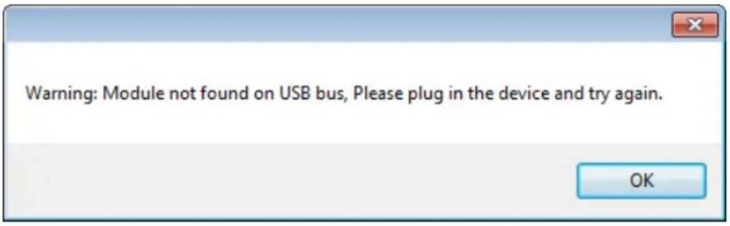
text_image
Warning: Module not found on USB bus, Please plug in the device and try again. OKClick OK to dismiss the dialog.
- The current version of the Receiver firmware is reported within the Software Version group, as highlighted in yellow:
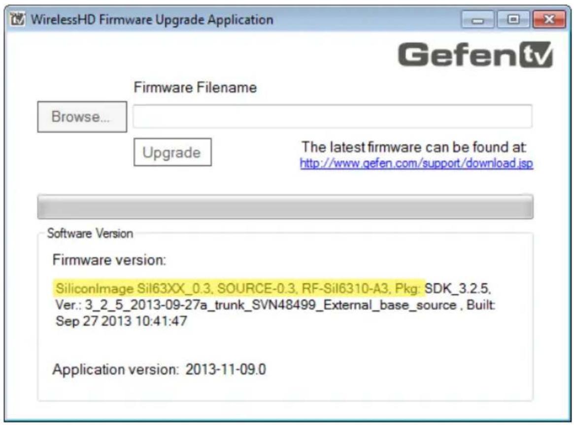
text_image
WirelessHD Firmware Upgrade Application Gefen tv Firmware Filename Browse... Upgrade The latest firmware can be found at: http://www.gefen.com/support/download.jsp Software Version Firmware version: SiliconImage Sil63XX_0.3, SOURCE-0.3, RF-Sil6310-A3, Pkg: SDK_3.2.5, Ver.: 3_2_5_2013-09-27a_trunk_SVN48499_External_base_source , Built: Sep 27 2013 10:41:47 Application version: 2013-11-09.0- Click the Browse... button and select the firmware for the Receiver unit. The Receiver unit will contain "sink" as part of the filename. The Sender unit will contain "source" as part of the filename.
- Click the Upgrade button.
- The following dialog will be displayed:
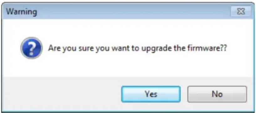
text_image
Warning Are you sure you want to upgrade the firmware?? Yes No-
Click the Yes button to continue with the upgrade process.
-
A progress bar will be displayed and the Firmware Upgrade button will read "Upgrading..." during the upgrade process.
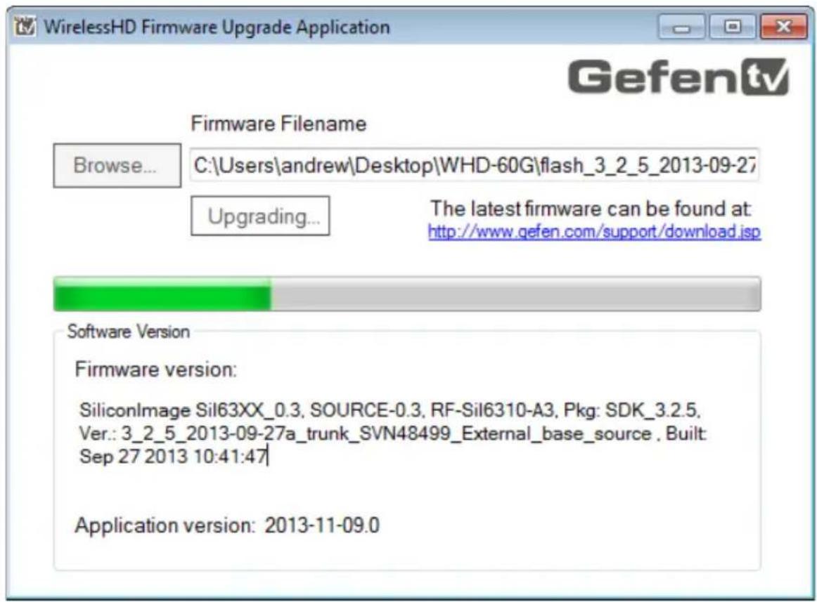
text_image
WirelessHD Firmware Upgrade Application Gefen tv Firmware Filename Browse... C:\Users\andrew\Desktop\WHD-60G\flash_3_2_5_2013-09-27 Upgrading... The latest firmware can be found at: http://www.gefen.com/support/download.jsp Software Version Firmware version: SiliconImage Sil63XX_0.3, SOURCE-0.3, RF-Sil6310-A3, Pkg: SDK_3.2.5, Ver.: 3_2_5_2013-09-27a_trunk_SVN48499_External_base_source , Built: Sep 27 2013 10:41:47 Application version: 2013-11-09.0- Once the upgrade process is complete, the following dialog will be displayed:
text_image
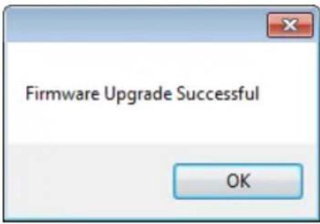
Firmware Upgrade Successful OK- Click the OK button to complete the upgrade process.
- Repeat steps 5 - 12 for the Sender unit and for each Sender and Receiver unit within the system.

WARNING: Always make sure that each Sender and Receiver unit within the system is using the same version of firmware. Mixing different versions of firmware between Sender and Receiver units may cause unstable operation.
Specifications
| Supported Formats | |
| Resolutions (max.) • 1080p Full HD | |
| Audio • Linear PCM | • DTS-HD Master AudioTM• Dolby® TrueHD |
| Electrical | |
| Frequency • 60 GHz | |
| Maximum Pixel Clock • 165 MHz | |
| Antenna Type (Sender / Receiver) • 24-Antenna Array | |
| Power Indicator (Sender / Receiver) • 1 x LED, blue | |
| Power Button (Sender / Receiver) • 1 x Tact-type | |
| Pair Button (Sender / Receiver) • 1 x Tact-type | |
| Connectors | |
| Video Input (Sender) • 1 x HDMI Type A | 19-pin, female |
| Video Output (Receiver) • 1 x HDMI Type A | 19-pin, female |
| Operational | |
| Power Input (Sender / Receiver) • 1 x 5V | / 2A DC |
| Operating Temperature • +32 to +104 °F | (0 to +40 °C) |
| Storage Temperature | • -4 to +158 °F (-20 to +70 °C) |
| Operating Humidity (Non-condensing) | • 10% to 90% |
| Storage Humidity (Non-condensing) • 5% | to 90% |
| Physical | |
| Dimensions (W x H x D) | • 3.5" x 2.8" x 0.6"(88mm x 72mm x 31mm) |
| Unit Weight (ea.) | • 0.2 lbs (0.1 kg) |
text_image
HDMI In GTV.WHD-80GS Power 5V DC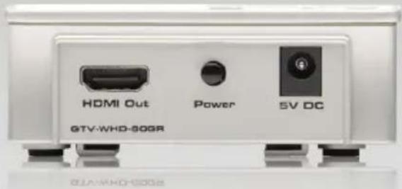
text_image
HDMI Out Power SV DC GTV-WHD-50GRStretch It, Switch It, Split It.
Gefen's Got It. ®
20600 Nordhoff St., Chatsworth CA 91311
1-800-545-6900 818-772-9100 fax: 818-772-9120
www.gefentv.com support@gefentv.com