GTB-UHD-HBT - Audio/video extender Gefen - Free user manual and instructions
Find the device manual for free GTB-UHD-HBT Gefen in PDF.


User questions about GTB-UHD-HBT Gefen
0 question about this device. Answer the ones you know or ask your own.
Ask a new question about this device
Download the instructions for your Audio/video extender in PDF format for free! Find your manual GTB-UHD-HBT - Gefen and take your electronic device back in hand. On this page are published all the documents necessary for the use of your device. GTB-UHD-HBT by Gefen.
USER MANUAL GTB-UHD-HBT Gefen
w/ RS-232, 2-way IR and POH
GTB-UHD-HBT
User Manual
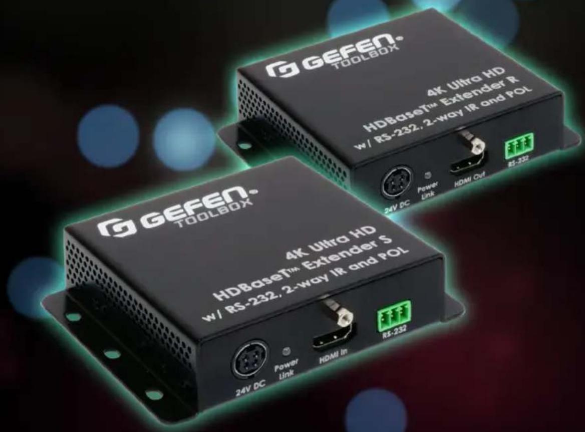
text_image
G GEFEN® TOOLBOX® 4K Ultra HD HDBase™ Extender R w/ RS-232, 2-way IR and POL 24V DC Power Link HDMI Out RS-232 G GEFEN® TOOLBOX® 4K Ultra HD HDBase™ Extender S w/ RS-232, 2-way IR and POL 24V DC Power Link HDMI In RS-232Release A0.6
- Read these instructions.
- Keep these instructions.
- Heed all warnings.
- Follow all instructions.
- Do not use this product near water.
-
Clean only with a dry cloth.
-
Do not block any ventilation openings. Install in accordance with the manufacturer's instructions.
-
Do not install or place this product near any heat sources such as radiators, heat registers, stoves, or other apparatus (including amplifiers) that produce heat.
-
Do not defeat the safety purpose of the polarized or grounding-type plug. A polarized plug has two blades with one wider than the other. A grounding type plug has two blades and a third grounding prong. The wide blade or the third prong are provided for your safety. If the provided plug does not fit into your outlet, consult an electrician for replacement of the obsolete outlet.
-
Protect the power cord from being walked on or pinched particularly at plugs, convenience receptacles, and the point where they exit from the apparatus.
-
Only use attachments/accessories specified by the manufacturer.
-
To reduce the risk of electric shock and/or damage to this product, never handle or touch this unit or power cord if your hands are wet or damp. Do not expose this product to rain or moisture.
-
Unplug this apparatus during lightning storms or when unused for long periods of time.
-
Refer all servicing to qualified service personnel. Servicing is required when the apparatus has been damaged in any way, such as power-supply cord or plug is damaged, liquid has been spilled or objects have fallen into the apparatus, the apparatus has been exposed to rain or moisture, does not operate normally, or has been dropped.
-
Batteries that may be included with this product and/or accessories should never be exposed to open flame or excessive heat. Always dispose of used batteries according to the instructions.
Gefen/Core Brands, LLC warrants the equipment it manufactures to be free from defects in material and workmanship. If equipment fails because of such defects and Gefen LLC is notified within the specified warranty period* from the documented** date of purchase, Gefen will, at its option, repair or replace the equipment, provided that the equipment has not been subjected to mechanical, electrical, or other abuse or modifications. This warranty is in lieu of all other warranties expressed or implied, including without limitation, any implied warranty or merchantability or fitness for any particular purpose, all of which are expressly disclaimed. Warranty period begins on the date of purchase by the original end-purchaser, as indicated on the proof of purchase document**. This Limited Warranty extends to the original end-user purchaser of the product, and is not transferrable to any subsequent purchaser(s) or owner(s). Customers outside the continental United States of America are responsible for shipping charges to and from Gefen.
* Warranty period:
Passive Copper Cables without any electronic circuitry: 30 days. Cables must be in their original condition.
Electronics:
• 2 years unless specified otherwise.
- 3 years if specifically noted as such on Gefen web-page of a product. Documented** purchases made on or after March 29, 2017 only.
** Proof of purchase must be a written document, as deemed acceptable by Gefen/Core Brands, LLC.
Technical Support
(707) 283-5900 (800) 472-5555
8:00 AM to 5:00 PM Monday - Friday, Pacific Time
support@gefen.com
Web
http://www.gefen.com
Mailing Address
Gefen
Core Brands, LLC
c/o Customer Service
1800 S McDowell Blvd
Petaluma, CA 94954 USA
Product Registration
Register your product here: http://www.gefen.com/kvm/Registry/Registration.jsp
- Gefen recommends using CAT-5e (or better) cables.
- Resolution will affect extension distance. 1080p Full HD can be extended up to 495 feet (150 meters) and is limited to 8-bit color depth. 4K resolutions can be extended up to 330 feet (100 meters). See HDBT (HDBaseT™) Mode (page 17) for details.
- Power Over Line (POL) is a Gefen proprietary technology that provides power over a single CAT-5e (or better) cable. A power supply (1 pc included) can be connected to either the Sender or Receiver unit.
- This product passes through the display's EDID to the source. If the display is capable of accepting Deep Color, the source must be manually configured to output 8-bit color. This is only applicable when using 4K x 2K resolutions and "long-run" modes. See HDBT (HDBaseT™) Mode (page 17) for more information.
- This product supports sources up to 4K 300 MHz (60 Hz 4:2:0 or 30 Hz 4:4:4). It is not compatible with sources that are capable of HDR or 4K 600 MHz (60 Hz 4:4:4).
- For Standard Range operation for up to 100m/330ft maximum distance, please make sure that the DIP Switch # 3 on the bottom of the Sender unit is in “OFF” position. To enable the Extended Range (up to 150m/495ft) mode, flip the DIP switch to “ON”. Please see DIP Switch Configuration (page 14) for information on all DIP switches.
- The information in this manual has been carefully checked and is believed to be accurate. However, Gefen assumes no responsibility for any inaccuracies that may be contained in this manual. In no event will Gefen be liable for direct, indirect, special, incidental, or consequential damages resulting from any defect or omission in this manual, even if advised of the possibility of such damages.
- The technical information contained herein regarding the features and specifications is subject to change without notice.
- For the latest warranty coverage information, refer to the Warranty and Return Policy under the Support section of the Gefen Web site at www.gefen.com.
© 2017 Gefen, LLC. All Rights Reserved. All trademarks are the property of their respective owners.
Gefen, LLC reserves the right to make changes in the hardware, packaging, and any accompanying documentation without prior written notice.
Features
• Extends 4K Ultra HD (3840 x 2160 @ 60Hz, 4:2:0 or @ 30Hz, 4:4:4), RS-232, and Bi-Directional R over a single CAT-5e cable up to 330 feet/100 meters (8-bit color)
- Extends 4K Cinema (DCI) (4096 x 2160 @ 24 or 30Hz 4:4:4), RS-232, and Bi-Directional IR over a single CAT-5e cable up to 330 feet/100 meters (8-bit color)
- Extends HDMI at 1080p Full HD, RS-232, and Bi-Directional IR over a single CAT-5e cable up to 330 feet/100 meters (up to 12-bit Deep Color)
- Extends HDMI at 1080p Full HD, RS-232, and Bi-Directional IR over a single CAT-5e cable up to 495 feet/150 meters (8-bit color)
• HDMI Features Supported:
▶ HDMI 2.0
▶ HDCP 2.2 and 1.4
▶ 12-bit Deep Color
LPCM 7.1 audio, Dolby® TrueHD, and DTS-HD Master Audio™ pass-through
▶ 3DTV pass-through
▶ CEC pass-through
▶ Lip Sync pass-through
- RS-232 Extension
• IR extension from Sender to Receiver and from Receiver to Sender - Gefen Bi-Directional POL feature provides power to the Sender or the Receiver unit over the link cable - only one side needs external power
- Uses Gefen's implementation of HDBaseT™ technology
• Advanced EDID Management - Firmware upgradable via RS-232
- Locking power connector
- Surface mountable
HDMI ^ 2.0
1080P PROGRESSIVE

4K ULTRA 60Hz, 4:2:0

HDCP2.2


text_image
4K CINEMA DCI, 4096 x 2160, 30HzPacking List
The following items are shipped with the 4K Ultra HD HDBaseT Extender w/ RS-232, 2-way IR and POL. If any of these items are not present in the box when you first open it, immediately contact your dealer or Gefen.
- 1 x 4K Ultra HD HDBaseT™ Extender w/ RS-232, 2-way IR and POL - Sender unit (GTB-UHD-HBT-S)
- 1 x 4K Ultra HD HDBaseT™ Extender w/ RS-232, 2-way IR and POL - Receiver unit (GTB-UHD-HBT-R)
- 1 x 6 ft. locking HDMI cable, M-M (CAB-HD-LCK-06MM)
- 1 x IR extender (EXT-RMT-EXTIRN)
- 1 x IR emitter (EXT-IREMIT)
- 1 x Adapter: 3-pin Phoenix-to-DB-9, M-F (ADA-PH-2-DB9-MF-AA or DA-PH-2-DB9-MF-AB)
- 1 x Adapter: 3-pin Phoenix-to-DB-9, M-M (ADA-PH-2-DB9-MM-AA or ADA-PH-2-DB9-MM-AB)
- 1 x 24V DC locking power supply (EXT-PS24U1AIP-6)
• 1 x Quick-Start Guide (QSG-GTB-UHD-HBT)
1 Getting Started
Introduction....2
Sender Unit 2
Receiver Unit....4
Installation....6
Connection Instructions....6
Sample Wiring Diagram 7
2 Basic Operation
LED Status 10
Bidirectional IR Control....11
Controlling the Source from the Viewing Location 11
Controlling the Display from the Source Location 12
Controlling the Source / Display from Different Locations.... 13
DIP Switch Configuration 14
EDID Management.... 15
HPD Mode....16
HDBT (HDBaseT™) Mode 17
RS-232 Mode 17
3 Advanced Operation
RS-232 Setup.... 20
Connecting RS-232 Devices 20
Commands....21
4 Appendix
Updating the Firmware 28
Single Update Procedure 28
Individual Update Procedure....30
Surface Mounting Instructions.... 32
Network Cable Diagram 33
Specifications 34
Index....35
This page left intentionally blank.
This page left intentionally blank.
4K ULTRA
HD
60Hz, 4:2:0
HDBaseT™ Extender
w/ RS-232, 2-way IR and POH
1 Getting Started
Sender Unit
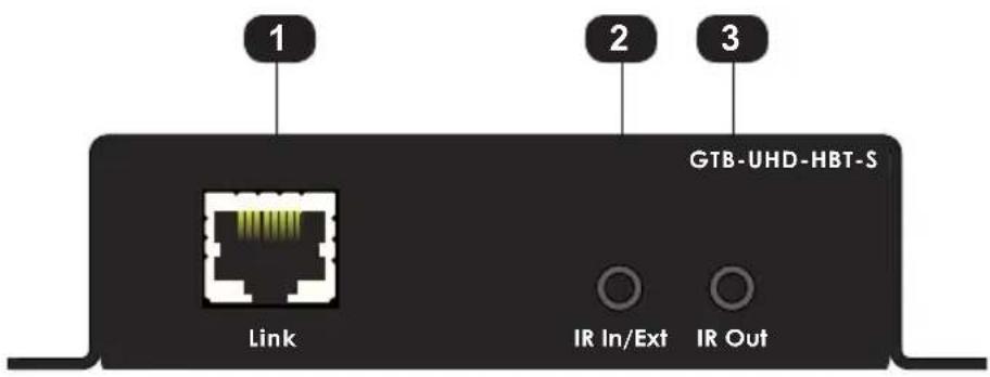
text_image
1 2 3 GTB-UHD-HBT-S Link IR In/Ext IR OutG GEFEN®
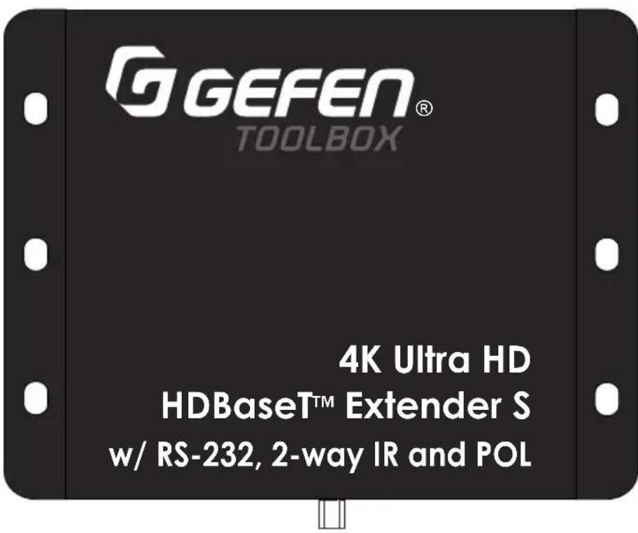
text_image
G GEFEN® TOOLBOX 4K Ultra HD HDBaseT™ Extender S w/ RS-232, 2-way IR and POL4
5
6
7

24V DC

| ID Name Description | ||
| 1 Link Connect a CAT-5e cable (or better), up to 495 feet (150 meters), from this port to the Link port on the Receiver unit. | ||
| 2 IR In/Ext | 3.5mm mini-stereo jack. Connect an IR Extender EXT-RMT-EXTIRN (1 pc included) to this port. Alternatively, connect a 3.5mm mini-stereo connector from this port to the output of an automation system with an electrical IR output.See Bidirectional IR Control (page 11) for more information on using IR. | |
| 3 IR Out Connect an EXT-IREMIT IR Emitter (1 pc included) from this port to the IR sensor of the device to be controlled.See Bidirectional IR Control (page 11) for more information on using IR. | ||
| 4 24V DC | This power receptacle can be used to connect the included 24V DC power supply (1 pc included). Only one power supply is required for the extender system to operate. The power supply can be connected to either the Sender or Receiver unit. | |
| 5 Power Link This LED indicator displays the current state of the Sender unit. See LED Status (page 10) for more information. | ||
| 6 HDMI In Use the included HDMI cable to connect an Ultra HD source to this HDMI port. | ||
| 7 RS-232 Connect the included RS-232 adapter cable from this port to the automation device. | ||
Receiver Unit
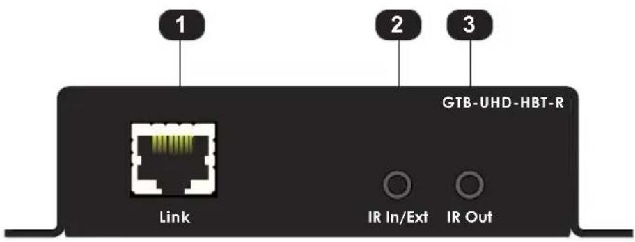
text_image
1 2 3 GTB-UHD-HBT-R Link IR In/Ext IR Out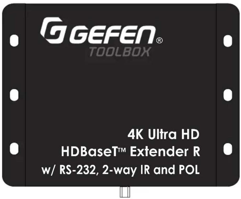
text_image
G GEFEN® TOOLBOX 4K Ultra HD HDBaseT™ Extender R w/ RS-232, 2-way IR and POL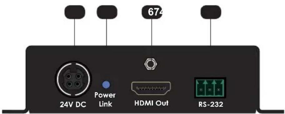
text_image
674 24V DC Power Link HDMI Out RS-232| ID Name Description | ||
| 1 Link Connect a CAT-5e cable (or better), up to 495 feet (150 meters), from this port to the Link port on the Sender unit. | ||
| 2 IR In/Ext 3.5mm mini-stereo jack. Connect an EXT-RMT-EXTIRN IR Extender (1 pc included) to this port. Alternatively, connect a 3.5mm mini-stereo connector from this port to the output of an automation system with an electrical IR output.See Bidirectional IR Control (page 11) for more information on using IR. | ||
| 3 IR Out | Connect an IR emitter EXT-IREMIT (1 pc included) from this port to the IR sensor of the device to be controlled.See Bidirectional IR Control (page 11) for more information on using IR. | |
| 4 24V DC | This power receptacle can be used to connect the included 24V DC power supply (1 pc included). Only one power supply is required for the extender system to operate. The power supply can be connected to either the Sender or Receiver unit. | |
| 5 Power Link This LED indicator displays the current state of the Receiver unit. See LED Status (page 10) for more information. | ||
| 6 HDMI Out Connect an HDMI cable from this port to an Ultra HD display. | ||
| 7 RS-232 Connect the included RS-232 adapter cable from this port to the device to be controlled. | ||
Connection Instructions
Video
- Connect the included HDMI cable between the Ultra Hi-Def source and the HDMI Import on the Sender unit.
- Connect an Ultra HD display to the HDMI Out port on the Receiver unit using another HDMI cable.
▶ CAT-5
- Connect a CAT-5e (or better) cable, up to 495 feet (150 meters) from the Link port on the Sender unit and the Link port on the Receiver unit.

Information
Resolution will affect extension distance. 1080p Full HD can be extended up to 495 feet (150 meters) and is limited to 8-bit color depth. 4K resolutions can be extended up to 330 feet (100 meters). Refer to HDBT (HDBaseT™) Mode (page 17) for details.
IR
- Refer to Bidirectional IR Control (page 11) for details on connecting IR devices.
RS-232
-
Connect the included 3-pin Phoenix-to-DB-9 (female) cable between the RS-232 controller and the Sender unit.
-
Connect the included 3-pin Phoenix-to-DB-9 (male) cable between the RS-232 device and the Receiver unit.
▶ Power
-
Connect the included 24V DC power supply (1 pc included) to the power receptacle on either the Sender or Receiver unit.
-
Connect the opposite end of the power supply to an available electrical outlet.
Sample Wiring Diagram
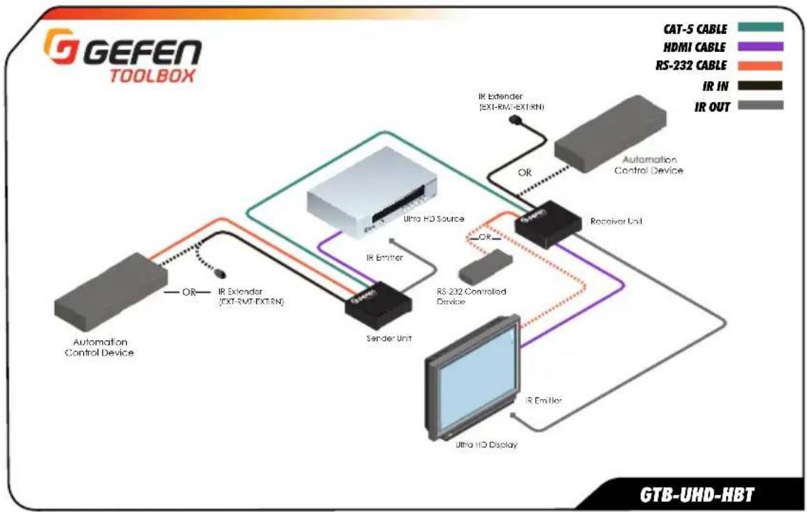
flowchart
graph TD
    A["Automation Control Device"] -->|OR| B["IR Extender (EXT-RMT-EXTRN)"]
    B --> C["Sender Unit"]
    C --> D["Ultra HD Source"]
    D --> E["Receiver Unit"]
    E --> F["RS-232 Controlled Device"]
    F --> G["Ultra HD Display"]
    G --> H["IR Emitter"]
    H --> I["IR Extender (EXT-RMT-EXTRN)"]
    I --> J["Satellite"]
    J --> K["Satellite"]
    K --> L["Satellite"]
    L --> M["Satellite"]
    M --> N["Satellite"]
    N --> O["Satellite"]
    O --> P["Satellite"]
    P --> Q["Satellite"]
    Q --> R["Satellite"]
    R --> S["Satellite"]
    S --> T["Satellite"]
    T --> U["Satellite"]
    U --> V["Satellite"]
    V --> W["Satellite"]
    W --> X["Satellite"]
    X --> Y["Satellite"]
    Y --> Z["Satellite"]
    Z --> AA["Satellite"]
    AA --> AB["Satellite"]
    AB --> AC["Satellite"]
    AC --> AD["Satellite"]
    AD --> AE["Satellite"]
    AE --> AF["Satellite"]
    AF --> AG["Satellite"]
    AG --> AH["Satellite"]
    AH --> AI["Satellite"]
    AI --> AJ["Satellite"]
    AJ --> AK["Satellite"]
    AK --> AL["Satellite"]
    AL --> AM["Satellite"]
    AM --> AN["Satellite"]
    AN --> AO["Satellite"]
    AO --> AP["Satellite"]
    AP --> AQ["Satellite"]
    AQ --> AR["Satellite"]
    AR --> AS["Satellite"]
    AS --> AT["Satellite"]
    AT --> AU["Satellite"]
    AU --> AV["Satellite"]
    AV --> AW["Satellite"]
    AW --> AX["Satellite"]
    AX --> AY["Satellite"]
    AY --> AZ["Satellite"]
    AZ --> BA["Satellite"]
    BA --> BB["Satellite"]
    BB --> BC["Satellite"]
    BC --> BD["Satellite"]
    BD --> BE["Satellite"]
    BE --> BF["Satellite"]
    BF --> BG["Satellite"]
    BG --> BH["Satellite"]
    BH --> BI["Satellite"]
    BI --> BJ["Satellite"]
    BJ --> BK["Satellite"]
    BK --> BL["Satellite"]
    BL --> BM["Satellite"]
    BM --> BN["Satellite"]
    BN --> BO["Satellite"]
    BO --> BP["Satellite"]
    BP --> BQ["Satellite"]
    BQ --> BR["Satellite"]
    BR --> BS["Satellite"]
    BS --> BT["Satellite"]
    BT --> BU["Satellite"]
    BU --> BV["Satellite"]
    BV --> BW["Satellite"]
    BW --> BX["Satellite"]
    BX --> BY["Satellite"]
    BY --> BZ["Satellite"]

Information
The wiring diagram, shown above, requires an additional IR emitter (Gefen part no. EXT-IREMIT) and IR extender (Gefen part no. EXT-RMT-EXTIRN).
This page left intentionally blank.
4K ULTRA
HD
60Hz, 4:2:0
HDBaseT™ Extender
w/ RS-232, 2-way IR and POH
2 Basic Operation
The Power Link LED indicator on the Sender and Receiver unit provides basic information on the current status of the 4K Ultra HD HDBaseT Extender w/ RS-232, 2-way IR and POL.
The information, in the table below, applies to both the Sender and Receiver unit.
| Status Description | |
| Solid blue • The Sender / Receiver unit is powered. | |
| • Link integrity between Sender and Receiver unit is good. | |
| Solid green • Link integrity is compromised. | |
| • Check the cable between the Link port on the Sender and Receiver unit. | |
Flashes blue / green | • Source device is not connected to the Sender unit.• Display (sink) device not connected to the Receiver unit. |
Controlling the Source from the Viewing Location
-
Connect an EXT-RMT-EXTIRN IR Extender (1 pc included) to the IR In/Ext port on the Receiver unit. If using an automation system, connect the 3.5mm mini-stereo connector from the IR In/Ext port on the Receiver unit to the automation system. IR signals are transmitted over the Link cable.
-
Connect an EXT-IREMIT IR Emitter (1 pc included) from the IR Out port, on the Sender unit, to the IR sensor window on the source device.
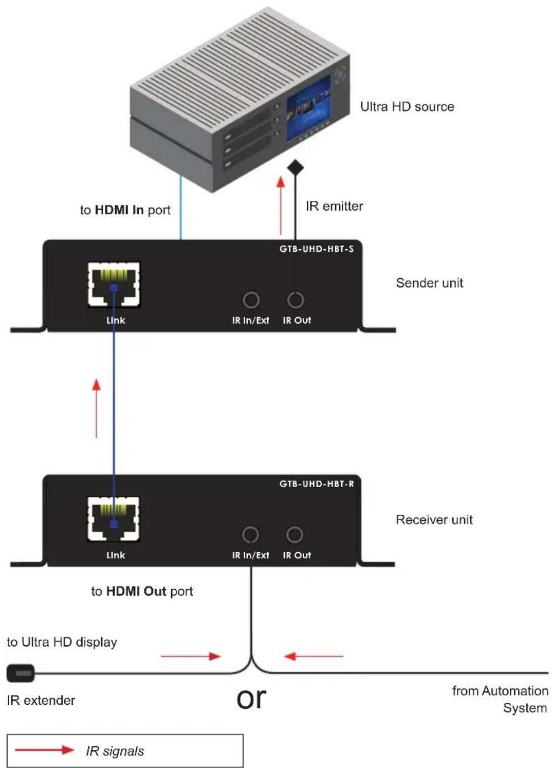
flowchart
graph TD
    A["Ultra HD source"] -->|to HDMI In port| B["Sender unit"]
    A -->|to HDMI In port| C["Receiver unit"]
    B --> D["Link"]
    B --> E["IR In/Ext"]
    B --> F["IR Out"]
    C --> G["Link"]
    C --> H["IR In/Ext"]
    C --> I["IR Out"]
    J["or"] --> K["from Automation System"]
    L["IR extender"] --> M["to Ultra HD display"]
    N["IR signals"] --> O["arrow to Ultra HD display"]
Controlling the Display from the Source Location
-
Connect an EXT-RMT-EXTIRN IR Extender (1 pc included) to the IR In/Ext port on the Sender unit. If using an automation system, connect the 3.5mm mini-stereo connector from the IR In/Ext port on the Receiver unit to the automation system. IR signals are transmitted over the Link cable.
-
Connect an EXT-IREMIT IR Emitter (1 pc included) from the IR Out port on the Receiver unit to the IR sensor on the display.
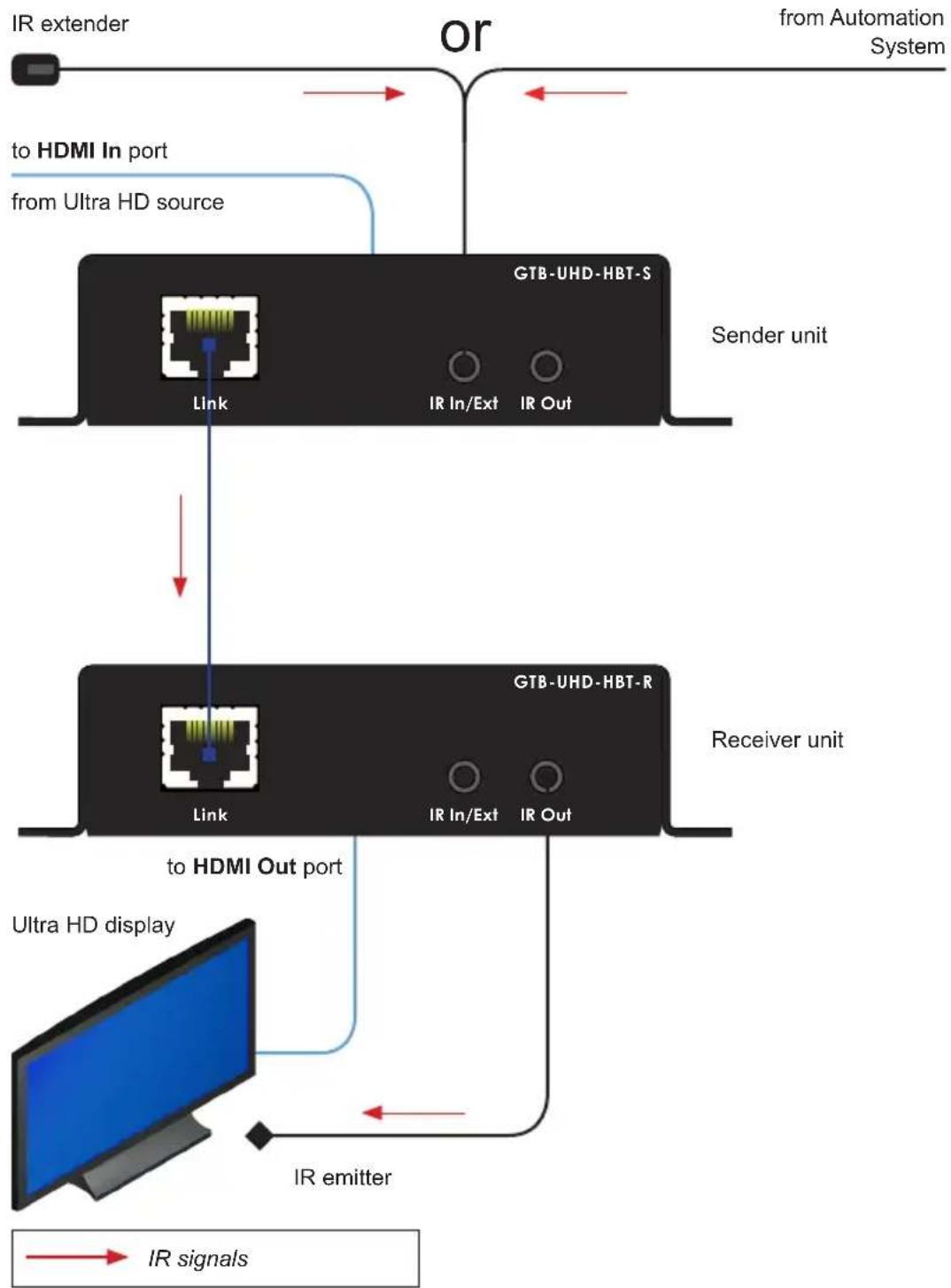
flowchart
graph TD
    A["IR extender"] --> B["or"]
    B --> C["from Automation System"]
    D["to HDMI In port"] --> E["from Ultra HD source"]
    E --> F["Sender unit"]
    F --> G["Link"]
    G --> H["or"]
    H --> I["or"]
    I --> J["Line"]
    J --> K["Line"]
    K --> L["or"]
    L --> M["Line"]
    M --> N["Line"]
    N --> O["Line"]
    O --> P["Line"]
    P --> Q["Line"]
    Q --> R["Line"]
    R --> S["Line"]
    S --> T["Line"]
    T --> U["Line"]
    U --> V["Line"]
    V --> W["Line"]
    W --> X["Line"]
    X --> Y["Line"]
    Y --> Z["Line"]
    Z --> AA["Line"]
    AA --> AB["Line"]
    AB --> AC["Line"]
    AC --> AD["Line"]
    AD --> AE["Line"]
    AE --> AF["Line"]
    AF --> AG["Line"]
    AG --> AH["Line"]
    AH --> AI["Line"]
    AI --> AJ["Line"]
    AJ --> AK["Line"]
    AK --> AL["Line"]
    AL --> AM["Line"]
    AM --> AN["Line"]
    AN --> AO["Line"]
    AO --> AP["Line"]
    AP --> AQ["Line"]
    AQ --> AR["Line"]
    AR --> AS["Line"]
    AS --> AT["Line"]
    AT --> AU["Line"]
    AU --> AV["Line"]
    AV --> AW["Line"]
    AW --> AX["Line"]
    AX --> AY["Line"]
    AY --> AZ["Line"]
    AZ --> BA["Line"]
    BA --> BB["Line"]
    BB --> BC["Line"]
    BC --> BD["Line"]
    BD --> BE["Line"]
    BE --> BF["Line"]
    BF --> BG["Line"]
    BG --> BH["Line"]
    BH --> BI["Line"]
    BI --> BJ["Line"]
    BJ --> BK["Line"]
    BK --> BL["Line"]
    BL --> BM["Line"]
    BM --> BN["Line"]
    BN --> BO["Line"]
    BO --> BP["Line"]
    BP --> BQ["Line"]
    BQ --> BR["Line"]
    BR --> BS["Line"]
    BS --> BT["Line"]
    BT --> BU["Line"]
    BU --> BV["Line"]
    BV --> BW["Line"]
    BW --> BX["Line"]
    BX --> BY["Line"]
    BY --> BZ["Line"]
Controlling the Source / Display from Different Locations

Information
Additional IR extenders (Gefen part no. EXT-RMT-EXTIRN) and IR emitters (Gefen part no. EXT-IREMIT) will be required for this configuration.
Using bidirectional IR, the 4K Ultra HD HDBaseT Extender w/ RS-232, 2-way IR and POL allows the source and/or display to be controlled from the Sender or Receiver unit. Refer to the diagram, below, for connection details. The video (HDMI) cables have been removed for clarity. IR signals are transmitted over the Link cable.
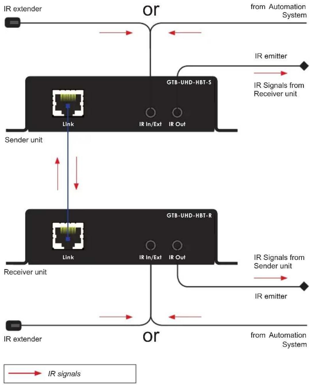
flowchart
graph TD
    A["IR extender"] --> B["or"]
    B --> C["from Automation System"]
    D["Link"] --> E["IR In/Ext"]
    D --> F["IR Out"]
    G["or"] --> H["from Automation System"]
    I["IR extender"] --> J["or"]
    J --> K["from Automation System"]
    L["IR emitter"] --> M["IR Signals from Receiver unit"]
    N["Link"] --> O["IR In/Ext"]
    N --> P["IR Out"]
    Q["or"] --> R["IR signals"]
    S["Link"] --> T["IR In/Ext"]
    S --> U["IR Out"]
    V["IR emitters"] --> W["IR Signals from Receiver unit"]
    X["Link"] --> Y["IR In/Ext"]
    X --> Z["IR Out"]
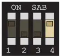
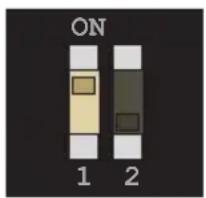
On the bottom of both the Sender and Receiver unit are a set of DIP switches. The Sender unit has a bank of four DIP switches. The Receiver unit has a bank of two DIP switches. See the following pages for DIP switch settings.
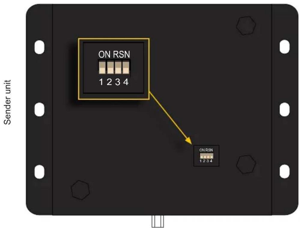
text_image
ON RSN 1 2 3 4 ON RSN 1 2 3 4 Sender unit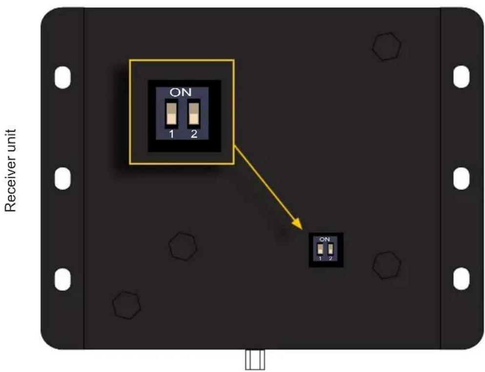
text_image
ON 1 2 ON 1 2 Receiver unitEach of the following sections describe the DIP switch settings that control each feature. DIP switches that are not related to a specific feature have been grayed-out. Note that DIP switch settings can be used independently or in conjunction with other features, as desired.

Information
DIP switch 2, on the Receiver unit, is not used and is reserved for optional future expansion.
EDID Management
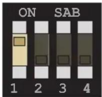
The 4K Ultra HD HDBaseT Extender w/ RS-232, 2-way IR and POL provides EDID management. The Sender unit can use the EDID from the sink device (downstream EDID) or modify the EDID, locally.
Description Sender unit Receiver unit
External EDID mode (default)
- Allows all video and audio features of the connected device to be passed to the source device.
text_image
ON SAB 1 2 3 4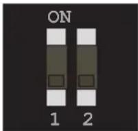
text_image
ON 1 2Internal EDID mode
- Copies the downstream EDID locally for use with HPD High Mode.
• See HPD Mode (page 16) for more information.
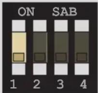
text_image
ON SAB 1 2 3 4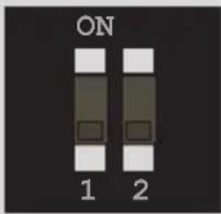
text_image
ON 1 2HPD Mode
HPD (Hot-Plug Detect) is an HDMI feature that senses if the HDMI cable is disconnected from the source or sink device. Once this occurs, the HDMI link is re-initialized if necessary. The 4K Ultra HD HDBaseT Extender w/ RS-232, 2-way IR and POL allows you to control the way HPD is handled.
Description Sender unit Receiver unit
HPD High
- Both DIP switch 1 and 2 must be in the down (OFF) position when setting HPD high.
- HPD is always high, even when the display is hot-plugged (disconnected from then reconnected to the source device).

text_image
ON SAB 1 2 3 4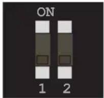
text_image
ON 1 2HPD Pass-through
- DIP switch 2 must be in the up (ON) position when setting HPD pass-through.
- The position of DIP switch 1 is ignored and can be in the up (ON) or down (OFF) position.
- HPD will toggle, depending on the HPD status of the display (sink) or source device.
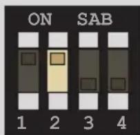
text_image
ON SAB 1 2 3 4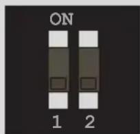
text_image
ON 1 2HDBT (HDBaseT ^TM ) Mode
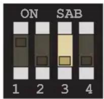
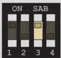
1080p Full HD can be extended up to 495 feet (150 meters) and is limited to 8-bit color depth. 4K resolutions can be extended up to 330 feet (100 meters) with deep color.
Description Sender unit Receiver unit
Normal mode (default)
- Allows all resolutions, up to 4K x 2K, to be extended up to 330 feet (100 meters).
text_image
ON SAB 1 2 3 4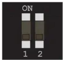
text_image
ON 1 2Long-reach mode
- Allows resolutions up to 1080p Full HD, at 8-bit, to be extended to a maximum distance of 495 feet (150 meters).
text_image
ON SAB 1 2 3 4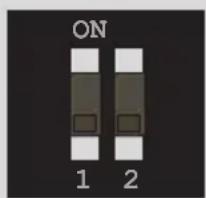
text_image
ON 1 2RS-232 Mode
Toggles between RS-232 pass-through mode and service mode.
Description Sender unit Receiver unit
Pass-through mode (default)
- RS-232 data is passed between the Sender and Receiver unit.
text_image
ON SAB 1 2 3 4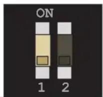
text_image
ON 1 2Service mode
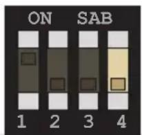
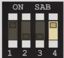
• Used to upgrade the firmware. See Updating the Firmware (page 28) for details.
text_image
ON SAB 1 2 3 4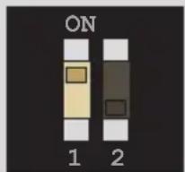
text_image
ON 1 2This page left intentionally blank.
4K ULTRA
HD
60Hz, 4:2:0
HDBaseT™ Extender
w/ RS-232, 2-way IR and POH
3 Advanced Operation
Connecting RS-232 Devices
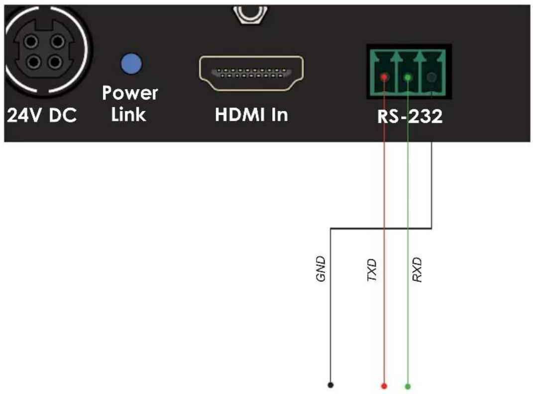
The 4K Ultra HD HDBaseT Extender w/ RS-232, 2-way IR and POL supports RS-232 pass-through, allowing the control of RS-232 devices using an automation system. The RS-232 interface is also used to upgrade the firmware and provides a small set of RS-232 commands. See Updating the Firmware (page 28) for details.
- Connect the included 3-pin Phoenix-to-DB-9 (M-F) adapter cable from the Sender unit to the automation device.
- Connect the included 3-pin Phoenix-to-DB-9 (M-M) adapter cable from the Receiver unit to the device to be controlled.
The following diagram shows the pin-out of the RS-232 port on the Sender unit. Note that only TXD (Transmit Data), RXD (Receive Data), and GND (Signal Ground) pins are used.
text_image
24V DC Power Link HDMI In RS-232 GND TXD RXD
Important
When sending RS-232 commands, a CR (0x0D) must be included.
| Command Description | |
| #fw_upgrade | Used to upgrade the firmware |
| #hdcp | Enables / disables HDCP detection |
| #help | Displays a list of available RS-232 commands |
| #power_always | Enables / disables “power always” mode |
#fw\_upgrade
Used to upgrade the firmware. See Updating the Firmware (page 28) for information on using this command.
Syntax
fw_upgrade param1
Parameters
None
Example
See Updating the Firmware (page 28) for information on using this command.
#hdcp
Enables / disables HDCP detection on the input. Some computers will enable HDCP if an HDCP-compliant display is detected. Set param1 = 0 to force the computer to ignore detection of an HDCP-compliant display.

Information
Setting param1 = 0 (HDCP disabled) does not decrypt HDCP content.
Syntax
hdcp param1
Parameters
param1
Integer
[0 ... 1]
| Value Description | |
| 0 | Disable HDCP |
| 1 | Enable HDCP |
Example
hdcp 0
Disable HDCP
stop HDCP/EDID detect
#help
The #help command displays the list of available RS-232 commands. Help on a specific command can be displayed when using param1.
Syntax
help param1
Parameters
param1 Command name (optional)
Example
help
Available cmds:
help
fw_upgrade
hdcp
power_always
help #hdcp
Cmd #hdcp: Change HDCP mode
Syntax: #hdcp param1
Param1 = 0 (disable hdcp) / 1 (enable hdcp)
#power\_always
Sets the power mode. The unit must be rebooted after changing the power mode.
Syntax
power_always param1
Parameters
param1
Integer
[0 ... 1]
| Value Description | |
| 0 | Power save |
| 1 | Power always |
Example
power_always 1
Set Power always mode To change power mode, Please reboot the unit
This page left intentionally blank.
This page left intentionally blank.
4K ULTRA HD 60Hz, 4:2:0
HDBaseT™ Extender
w/ RS-232, 2-way IR and POH
4 Appendix
There are two methods for updating the 4K Ultra HD HDBaseT Extender w/ RS-232, 2-way IR and POL. The recommended method is to update both units at the same time by leaving the Sender and Receiver unit connected. Updating the Sender unit will update the Receiver unit (or vice versa). The second method is to update the Sender and Receiver unit separately.
Single Update Procedure
This method is recommended and can be used in situations where disconnecting the system is impractical or difficult. The power supply must be connected to either the Sender or Receiver unit. The update procedure can take place at the Sender or Receiver location.
- Download the latest firmware here: http://www.gefen.com/support/download.jsp
- Extract the contents of the .zip file to the desktop on your computer.
- Disconnect the power supply from the Sender (or Receiver) unit.
- Set the following DIP switches on the Sender and Receiver units:
▶ Sender unit
Set DIP switch 4, on the bottom of the Sender unit, to the ON position:
text_image
ON SAB 1 2 3 4▶ Receiver unit
Set DIP switch 1, on the bottom of the Receiver unit, to the ON position:
text_image
ON 1 2- Connect the included RS-232 cable between the Sender (or Receiver) unit and the computer.
-
Launch a terminal emulation program. In this example, we will be using Windows® Hyperterminal.
-
Assign the following serial port settings in Hyperterminal:
| Description Setting | |
| Baud rate | 19200 |
| Data bits | 8 |
| Parity | None |
| Stop bits | 1 |
| Hardware flow control | None |
- Reconnect the power supply to the Sender (or Receiver) unit.
- Type the following in the terminal application:
fw_upgrade
- Press the [ENTER] key.
- When prompted, press 1 on the computer keyboard.
- Click Transfer > Send File...
- Select the firmware file: ELR_BIDIR_[version].bin.
- Select the YModem protocol and click the Send button.
- After the upgrade process is complete, the unit will automatically reboot.
- Both the Sender and Receiver units are now updated.
Individual Update Procedure
This method requires that the Sender and Receiver unit are updated separately. Unless there is a specific reason, the Single Update Procedure (page 28) is recommended.
- Download the latest firmware here: http://www.gefen.com/support/download.jsp
- Extract the contents of the .zip file to the desktop on your computer.
- Disconnect the Sender and Receiver unit from the system. Make sure the power is disconnected from both the Sender and Receiver unit.
- Set the following DIP switches on the Sender and Receiver units:
▶ Sender unit
Set DIP switch 4, on the bottom of the Sender unit, to the ON position:
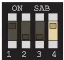
text_image
ON SAB 1 2 3 4▶ Receiver unit
Set DIP switch 1, on the bottom of the Receiver unit, to the ON position:

text_image
ON 1 2- Connect the included RS-232 cable between the unit and the computer.
- Launch a terminal emulation program. In this example, we will be using Windows® Hyperterminal.
(continued on next page)
- Assign the following serial port settings in Hyperterminal:
| Description Setting | |
| Baud rate | 19200 |
| Data bits | 8 |
| Parity | None |
| Stop bits | 1 |
| Hardware flow control | None |
- Connect the power supply to the unit.
- Type the following in the terminal application:
fw_upgrade
- Press the [ENTER] key.
- When prompted, press 1 on the computer keyboard.
- Click Transfer > Send File...
- Select the firmware file: ELR_BIDIR_[version].bin.
- Select the YModem protocol and click the Send button.
- After the upgrade process is complete, the unit will automatically reboot.
- Connect the RS-232 cable to the other unit and repeat steps 8 - 15.
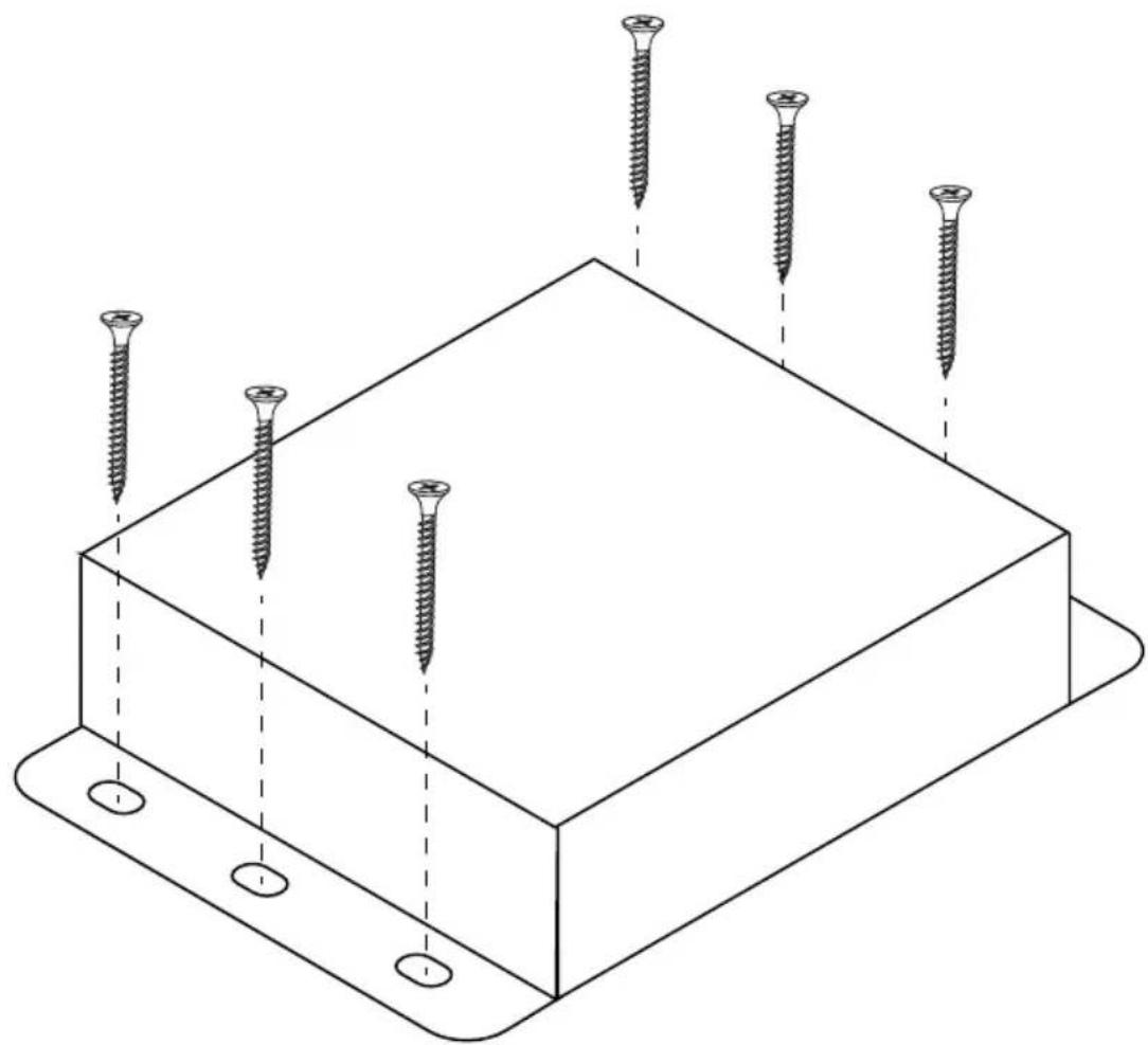
The Sender and Receiver units can be mounted on any flat surface, as shown below (mounting screws are not included). To accommodate for connection and disconnection of the cables, please leave sufficient clearance between the two edges of the unit that house the connectors and any walls or vertical surfaces.
For installation on a drywall surface, use a #6 drywall screw. When installing, it is recommended to use the center hole on a stud.
natural_image
Isometric line drawing of a rectangular electronic component with six screws inserted, no text or symbols presentFront of RJ-45 Connector
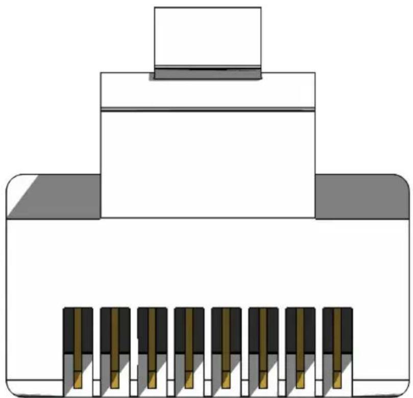
natural_image
Pure diagram of a mechanical or electrical component with no text, numbers, or symbols visible12345678
Gefen recommends the TIA/EIA-568-B wiring option. Use the following table when terminating cables in the field.
Pin Color Description
| 1 Orange / White TD+ (Transmit Data, positive differential signal) |
| 2 Orange TD- (Transmit Data, negative differential signal) |
| 3 Green / White RD+ (Receive Data, positive differential signal) |
| 4 Blue Unused |
| 5 Blue / White Unused |
| 6 Green RD- (Receive Data, negative differential signal) |
| 7 Brown / White Unused |
| 8 Brown / White Unused |







| Supported Formats | |
| Video • 4096 x 2160 | • 3840 x 2160• 1920 x 1200 (WUXGA)• 1080p Full HD |
| Audio • Linear PCM (7.1 channels) | • Dolby Atmos® and Dolby® TrueHD• DTS:XTM and DTS-HD Master AudioTM |
| Connectors & Indicators | |
| HDMI In (Sender) • 1 x HDMI Type A, 19-pin, female | |
| HDMI Out (Receiver) • 1 x HDMI Type A, 19-pin, female | |
| Link (Sender / Receiver) • 1 x RJ-45, shielded, female | |
| IR In/Ext (Sender / Receiver) • 1 x 3.5mm, female | |
| IR Out (Sender / Receiver) • 1 x 3.5mm, female | |
| RS-232 (Sender / Receiver) • 1 x 3-pin Phoenix-type, female | |
| Power (Sender / Receiver) • 1 x 4-pin, locking, female | |
| Power Link (Sender / Receiver) • 1 x LED, bi-color, blue / green |
| Operational | |
| Maximum Pixel Clock • 300 MHz | |
| Power Input • 24V DC | |
| Power Consumption • 12 Watts (max.) | |
| Operating Temperature • +32 to +113 °F (0 to +45 °C) | |
| Storage Temperature | • -4 to +185 °F (-20 to +85 °C) |
| Storage Humidity (RH) | • 0% to 90%, non-condensing |
| Operating Humidity (RH) | • 5% to 90%, non-condensing |
| MTBF | • 50,000 Hours |
| Physical | |
| Dimensions (W x H x D)(Sender / Receiver) | • 4.3" x 1" x 3.2"(110mm x 26mm x 85mm) |
| Unit Weight (ea.) | • 0.4 lb (0.2 kg) |
B
Bidirectional IR Control 11
C
Commands 21
fw_upgrade 21
hdcp 22
help 23
power_always 24
Connection Instructions 6
D
DIP Switch Configuration 14
E
EDID Management 15
F
Features vi
H
HDBT (HDBaseT™) Mode 17
HPD Mode 16
|
Installation 6
L
LED Status 10
Long-reach mode 17
M
Mounting Instructions 32
N
Network Cable Diagram 33
0
Operating Notes v
P
Packing List vii
R
Receiver Unit 4
RS-232
commands 21
mode 17
RS-232 Setup 20
S
Safety Instructions ii
Sender Unit 2
Specifications 34
T
Table of Contents viii
Technical Support iv
U
Updating the Firmware individual update procedure 30 single update procedure 28
W
Warranty Information iii
Wiring Diagram 7

GEFEN
1800 S McDowell Blvd. Petaluma CA 94954
(707) 283-5900 (800) 472-5555