Conqueror (2015) - Caravan Swift - Free user manual and instructions
Find the device manual for free Conqueror (2015) Swift in PDF.


| Product Type | Touring Caravan |
| Brand | Swift |
| Model | Conqueror (2015) |
| Overall Length | 7.5 m |
| Overall Width | 2.3 m |
| Overall Height | 2.6 m |
| Interior Height | 1.95 m |
| Mass in Running Order (MRO) | 1,350 kg |
| Maximum Weight | 1,600 kg |
| Number of Berths | 6 |
| Number of Axles | Single axle |
| Tire Size | 195/70 R15 |
| Power Supply | 12V DC (battery) and 230V AC (hookup) |
| Water System | Onboard fresh water tank (40L) and external mains connection |
| Gas System | Two 6kg gas bottles, gas hob, oven, and heating |
| Refrigerator | Absorption fridge (90L) |
| Heating System | Gas/ Electric blown air heating |
| Toilet | Swivel cassette toilet |
| Shower | Separate shower compartment |
| Main Functions | Sleeping, cooking, dining, washroom facilities |
| Maintenance | Annual service recommended; check seals, gas system, and wheel bearings |
| Cleaning | Use non-abrasive cleaners; wipe down surfaces with damp cloth |
| Safety | Smoke alarm, carbon monoxide alarm, fire extinguisher, emergency exit |
| Spare Parts | Available from authorised Swift dealers; refer to manual for part numbers |
| Repairability | DIY for basic components; gas and electrical work by professionals |
Frequently Asked Questions - Conqueror (2015) Swift
User questions about Conqueror (2015) Swift
0 question about this device. Answer the ones you know or ask your own.
Ask a new question about this device
Download the instructions for your Caravan in PDF format for free! Find your manual Conqueror (2015) - Swift and take your electronic device back in hand. On this page are published all the documents necessary for the use of your device. Conqueror (2015) by Swift.
USER MANUAL Conqueror (2015) Swift
Thank you for deciding to buy one of our new caravans.
We are sure you will enjoy many happy hours in it and we hope the information and hints in this handbook will heighten your enjoyment.
The handbook has been designed to give you a general guide to the care, use and maintenance of your caravan. Whether you are a new or an experienced caravanner the hints will help to protect your investment.
The information contained will answer most of your queries, but if there are any aspects which are not covered please consult your appointed dealer. We would suggest you make a note of your dealers name and contact information below.
Throughout the season, specifications and equipment details contained within this handbook may change. Please refer to our online handbooks (www.swiftgroup.co.uk) for the most up-to-date version of your handbook.
Customers should note that all caravans are supplied with two handbooks, the User Handbook which contains general information for the use and care of your product and the Technical Handbook, which contains technical information, weights and dimensions of your product.
Dealer Name:
Telephone Number:
E-mail:
Serial Number:

Swift Talk
Swift Talk is the central forum for the Swift community online. A place for all those united in their love of caravanning, motorhomes, holiday homes and touring in general, to share their experiences, meet new friends and find out a world of information on how to enjoy their touring lifestyle.
The site is packed full of features that actively encourage members, not only to liaise with the Swift Group via the forums, but also interact with each other through publishing their own content, uploading and sharing photos and video, and even posting their own blogs for the community to follow.
Swift Talk is the first place to learn about new product launches, events and Swift Group news, it's also the first place customers can go to as a quick reference to frequently asked questions or to actively take part in the forums; providing valuable feedback on Swift Group products and customer service.
The online community can even be used to create your own groups, perfect for Owners' Clubs, dealers and exhibitors to attract new
members, publicise and build awareness for upcoming events, rallies and shows.
Anyone who owns, uses, or is thinking of buying a Swift Group caravan, motorhome or holiday home, or would just like to be part of the growing Swift community is actively encouraged to sign up, create their own content, and start talking!
Just visit www.swift-talk.co.uk and become part of a unique online experience.
CONTENTS
Warranty 5
Towing code 13
Safety & security 36
Services 48
Electrics 79
Fitted equipment 101
Maintenance 198
Useful information 232
WARRANTY INFORMATION
Warranty and guarantee cover 6
Change of ownership 8
What to do if you require assistance 8
Supplier contacts 9
Touring caravans - annual service/inspection record 10
Annual service / inspection record stamps 11
WARRANTY
All the illustrations and descriptive matter in this handbook are intended to give a general idea of the caravan. Changing market and supply situations and our policy of continuous product development may prevent us from maintaining the exact specifications detailed in this handbook. We therefore reserve the right to alter specifications as materials and conditions demand.
Dealers are not agents of Swift Group Limited ("Swift") and have absolutely no authority to bind the manufacturer by any express or implied undertaking or representation.
Your caravan has three warranties:
SuperSure Warranty
For all parts or fittings of your caravan other than the body shell, Swift will repair (or at its option, replace) any defective parts or fittings for 3 years from the date of purchase (or hire purchase) subject to conditions, terms and exclusions below.
Body Shell Warranty
For the body shell, Swift will repair (or at its option, replace) any defects with the body shell for 6 years from the date of purchase (or hire purchase), subject to the conditions, terms and exclusions below.
Extended Body Shell Warranty
For the first owner, Swift will repair (or at its option, replace) any defects with the body shell for 10 years from the date of purchase (or hire purchase), subject to the conditions, terms and exclusions below.
Conditions
- You must ensure that your caravan has had an Annual Service (see clause 2 below) within 90 days before or 60 days after each anniversary of the original date of purchase. In order to preserve your SuperSure Warranty, the third Annual Service must be carried out before the expiry of the 36 month period from the original date of purchase. In order to preserve your Body Shell Warranty, the sixth Annual Service must be carried out before the expiry of the 72 month period from the original date
of purchase. In order to preserve your Extended Body Shell Warranty, the tenth Annual Service must be carried out before the expiry of the 120 month period from the original date of purchase. If you have not performed an Annual Service then Swift will not be obliged to perform any work under the applicable warranty. Original VAT invoices must be retained as proof that Annual Services have been carried out.
-
The Annual Service must be carried out in accordance with the requirements in this handbook. You will be responsible for any charges made for an Annual Service. If the Annual Service is performed by an authorised Swift Group Service Centre then Swift warrants that the Annual Service has been performed correctly. If the Annual Service is performed by an unauthorised repairer or service centre then the Annual Service has not been performed in accordance with the requirements in this handbook and/or work has been performed on your caravan that is defective or faulty, then Swift will not be obliged to perform any work under this Warranty (insofar as it relates to defective or faulty work or defective Annual Service).
-
All new caravans must be registered with Swift within 6 weeks of purchase as new.
-
The benefit of the SuperSure Warranty and Body Shell Warranty may be transferred to a new owner if the caravan is re-sold, provided that the caravan has been serviced in accordance with the requirements of this handbook, and details of the change of ownership have been supplied to Swift using the change of ownership form set out in this handbook as soon as reasonably practicable after the change.
-
The benefit of the Extended Body Shell Warranty is non transferable to new owners and applies only to the original registered owner
-
If any repairs are identified as being necessary during an Annual Service or otherwise, Swift will only pay for Warranty work performed by an authorised Swift Group Service Centre. The caravan must
be made available to an authorised Swift Group Service Centre within 6 weeks of the date the repair need was identified for the work to be carried out. The cost of transporting, towing or moving the caravan by any means to or from the place of repair is the responsibility of the owner.
- The SuperSure Warranty, the Body Shell Warranty and/or the Extended Body Shell warranty only apply to caravans purchased and used primarily within the UK, which means that the caravan is not used for continuous journeys outside of the UK of longer than 90 days per journey.
Terms
- The Body Shell Warranty and Extended Body Shell Warranty cover any defect with the panels and seams of the caravan. This includes body leaks, delamination of panels or floor, water ingress through any permanently sealed seam joints.
Note: Only jack up your caravan when it is coupled up to the car with its handbrake applied and in 1st gear (engine off).
- The SuperSure Warranty will cover in the first 12 months any defect other than those specified in the Exclusions below.
-
In years 2 and 3 of the SuperSure Warranty, the Warranty will only cover any defect with the following components:
-
Water system, heater, fresh water tank, water pump, water gauges, taps and shower heads:
• Heating system and components; - Main proprietary items (for example fridge, toilet, cooker);
- Chassis and associated parts;
- Auxiliary electrics ; and
- Windows (excluding window furniture and blinds).
In years 2 and 3 of the SuperSure Warranty, any defect specified in the Exclusions will not be covered.
Exclusions
-
Swift shall not be liable under this Warranty for any defect related to or arising from the following:
-
The failure of a component for reasons of fair wear and tear;
- Damage resulting from freezing, fire, overheating or accidents (whether caused by the user or a third party);
- Misuse of any component;
- Normal deterioration, corrosion, intrusion of foreign or harmful bodies, lack of servicing or negligence of any person other than Swift which causes stoppage of or impairment to the function of any component of the caravan;
- Replacement of parts which have reached the end of their effective working life because of age and/or usage;
- Cleaning or adjustment of any assemblies;
- Cosmetic finishes to kitchen sinks, cooker tops, vanity units, shower trays; and/or
- Routine maintenance items which are part of the annual service including brake shoes, one shot nuts, lubricants, AKS pads, rubber gas hose, the cleaning of the heater and fridge flues, the replacement of gas jets, the resealing and/or replacement of shower room sealant, and the adjustment and lubrication of locks.
-
In addition to the exclusions above, in years 2 and 3 of the SuperSure Warranty Period, Swift Group Limited shall not be liable under this Warranty for any defects related to:
-
Caravan Alloy wheel (after 15 months from date of purchase)
- Omni-vent roof-lights (after 24 months from date of purchase)
- GRP sheet material (after 24 months from date of purchase)
Swift shall also not be liable under the SuperSure, Body Shell and Extended Body Shell Warranties if the Caravan has been neglected, misused, modified or use for hire or
ASSISTANCE
reward or if the identification marks (chassis/VIN numbers) have been removed or defaced. The caravan will be deemed to have been neglected if it has not been serviced and maintained as stated in this handbook or any repairs being identified as necessary at an Annual Service or by a Swift Group Service Centre have not been carried out in a reasonable time.
You have legal rights under UK law governing the sale of consumer goods. These warranties do not affect your legal rights.
The name and address of the warranty and Guarantee provider is:
Swift Group Limited, Dunswell Road, Cottingham, East Yorkshire, HU16 4JX.
In the unusual event that a fault develops and you need to claim under Body Shell Warranty or the SuperSure Warranty, your first contact should normally be made through the dealer from whom the caravan was purchased. If this is not feasible then a claim may be dealt with by a different authorised Swift Group Service Centre, please contact the Swift Group Customer Care Department on 01482 875740 or enquiring on our website: www.swiftleisure.co.uk directly for details.
Change of ownership
There is a £50.00 administration fee to transfer the remainder of any 3 year 'Supersure warranty' and the 6 year 'body shell' warranty, details of how to do this can be found at the rear of this handbook.
The 'Extended Body Shell Warranty' is non transferable.
What to do if you require assistance
Congratulations on purchasing your new caravan. We are confident that you will enjoy many happy holidays. However, should you have an enquiry or require assistance with a problem, we hope that this guide will be of assistance to you.
If you have a problem, or enquiry with regards to your new caravan, please follow these steps:
- Check the Owners Handbook, paying particular attention to the fault finding advice at the back of the book.
- Contact your supplying dealer for assistance.
If you need to contact the Swift Group, please be aware of the following:
- When contacting Swift Customer Care, please quote your name, postcode and serial number of your caravan.
- In most instances, the Customer Care Team will involve your dealer in resolving the issue you are experiencing.
- If you are contacting the company by email, letter or fax, the Customer Care Team will respond to you within five working days from the date of receiving the correspondence.
- If you are calling the Customer Care Team, please avoid where possible, Mondays and lunch times.
- Please be aware that the Swift Group cannot send parts direct from the factory. In all cases, without exception, your dealer must place the order for you.
Supplier contacts
A number of Swift Group suppliers manage their own Technical and Warranty related queries. Where a customer has a question relating to a product manufactured by a company listed below, we would advise that the first contact should be directly with them.
SARGENT
AL-KO
truma
THETFORD Corporation
Aide
Dometic
Sargent Electrical Services
Unit 39, Tokenspire Business Park, Beverley, East Yorkshire, HU17 0TB
Phone: 01482 678981
Fax: 01482 678987
E-mail: support@sargentltd.co.uk
AL-KO Kober Limited
South Warwickshire Business Park
Kineton Road, Southam,
Warwickshire, CV47 0AL
Fax: 01926 818562
Email: mail@al-ko.co.uk
Truma UK Ltd.
Park lane, Dove Valley Park,
South Derbyshire, DE65 5BG
Phone: 01283 586020
Fax: 01283 586029
technical@trumauk.com
Thetford Ltd.
Unit 6, Brookfields Way, Manvers,
Dearne Valley, Rotherham,
South Yorkshire, S63 5DL
Phone - 0844 997 1960
Fax - 0844 997 1961
Email - infogb@thetford.eu
Alde International (UK) Ltd
Huxley Close, Park Farm South,
Wellingborough, Northants, NN8 6AB
Phone: 01933 677765
Fax: 01933 674975
Email: info@alde.co.uk
Dometic (UK) Ltd
Dometic House, The Brewery,
Blandford St Mary, Dorset, DT11 9LS
Phone: 0844 626 0133
Email: technical@dometic.co.uk
SERVICE INSPECTION
Touring caravans - annual service/inspection record
In order to comply with the warranty, you must have your caravan inspected and serviced by an authorised Swift Group Service Centre at least once per year.
It is important that the Owner's Handbook is stamped on the appropriate page by the authorised Swift Group Service Centre. Failure to do this will invalidate the warranty and the transfer of the warranty on the change of ownership.
The inspection should take approximately two to four hours and will cover the areas dealt with in the annual service check list. Any areas requiring service and/or maintenance will be highlighted by your dealer and we recommend that you authorise any necessary work to be carried out.
Note: It is essential, to validate the warranty, that an annual inspection be carried out by an authorised Swift Group Service Centre covering the items listed.
- Damp and lamination test.
- Coupling head and breakaway cable.
- Jockey wheel.
- Chassis and chassis to body security.
- Corner steadies.
- Tyres and tyre pressures.
- Torque wheel nuts.
- Brake rods and linkages.
- Hub bearings, brakes and brake shoes.
- Handbrake operation and performance.
- Suspension and shock absorbers (if fitted).
12.13 pin plug and cables. - Road lights, wiring and reflectors.
- Internal lights and 12V DC system.
- Water heater - gas and 230V AC (if fitted).
- Hob, grill and oven (if fitted).
-
Refrigerator 230V AC, 12V DC and gas.
-
Gas system.
- Water pump, taps and water system.
- Mains 230V AC system.
- Windows and fittings.
- Smoke alarm and battery.
- Roof lights.
- Furniture hinges/stays etc.
- Exterior locks and hinges.
- Grab handle security.
- All internal vents.
- Oil seals.
- Blinds and fly screens (if fitted).
- Carbon Monoxide detector and battery
| Annual service / inspection record stampsCaravan model:Year:Chassis Number: | 1st serviceDate:Dealer's StampWe certify that an annual service has been carried out in accordance with the handbook. |
| 2nd serviceDate:Dealer's StampWe certify that an annual service has been carried out in accordance with the handbook. | 3rd serviceDate:Dealer's StampWe certify that an annual service has been carried out in accordance with the handbook. |
| 4th serviceDate:Dealer's StampWe certify that an annual service has been carried out in accordance with the handbook. | 5th serviceDate:Dealer's StampWe certify that an annual service has been carried out in accordance with the handbook. |
| 6th serviceDate:Dealer's StampWe certify that an annual service has been carried out in accordance with the handbook. | 7th serviceDate:Dealer's StampWe certify that an annual service has been carried out in accordance with the handbook. |
| 8th serviceDate:Dealer's StampWe certify that an annual service has been carried out in accordance with the handbook. | 9th serviceDate:Dealer's StampWe certify that an annual service has been carried out in accordance with the handbook. |
| 10th serviceDate:Dealer's StampWe certify that an annual service has been carried out in accordance with the handbook. | 11th serviceDate:Dealer's StampWe certify that an annual service has been carried out in accordance with the handbook. |
| 12th serviceDate:Dealer's StampWe certify that an annual service has been carried out in accordance with the handbook. | 13th serviceDate:Dealer's StampWe certify that an annual service has been carried out in accordance with the handbook. |
| 14th serviceDate:Dealer's StampWe certify that an annual service has been carried out in accordance with the handbook. | 15th serviceDate:Dealer's StampWe certify that an annual service has been carried out in accordance with the handbook. |
TOWING CODE
Caravan towing code 14
Caravan terms 14
Towing vehicle terms 16
Measurement of nose weight 16
Type of driving licence held 17
Glossary & checklist 17
Useful memory aid 19
Preparing for the road 20
Tyre Maintenance 23
The Tyre Law 24
Pre tow check list & hitch up for AKS3004 stabiliser 25
13 Pin Socket 27
Towcar electrics.... 28
Breakaway Cables 29
Mirrors 31
Moving off 31
Reversing 31
Speed limits 31
Caravan handling 32
Motorway driving 32
AL-KO spare wheel carrier tips 32
Changing a wheel 33
Wheel Bolt tightening 33
Jacking points 33
Stopping on a hill 34
Arrival on site 34
Exterior Door 35
AKS 3004 35
TOWING CODE
Caravan towing code
This Code of Practice contains recommendations jointly reviewed and agreed by the following organisations:
The National Caravan Council
The Caravan Club
The Camping and Caravanning Club
The Caravan Writers Guild
The Department for Transport
Scope of the Code
The Code applies to all trailer caravans of maximum laden weight not exceeding 3500 kg (7,700 lbs), overall width not exceeding 2.3m (7ft 6in approximately) and overall length not exceeding 7m (23ft approximately), excluding the drawbar and coupling.
This is legally the maximum size of trailer that can be towed by a motor vehicle with a maximum gross weight of less than 3500 kg.
Caravan terms
Mass in Running Order:
The mass of the caravan equipped to the caravan manufacturer, standard specification.
The MRO includes an allowance for gas, the electric hook up, cables as well as the fluids and liquids required for the normal caravan operation.
Note: The mass of the caravan in running order contains provision for the masses of liquids, gas etc. (see Mass in Running Order in the Technical Handbook). Part of this provision can also be utilised as additional payload, if for example, you wish to travel with water tanks empty or with no gas cylinders.
Maximum User Payload:
The maximum allowable weight to be put into the caravan whilst it is being towed. This is made up of the personal effects and the optional equipment payloads.
The user payload is the difference between the Maximum Technically Permissible Laden Mass and the Mass in Running Order.
The Mass in Running Order + Personal Effects + Optional Equipment = Maximum Technical Permissible Mass or MRO + PE + OE = MTPLM
Personal Effects
Those items which a user can choose to carry in a caravan.
Note: The Personal effects payload includes an allowance of 20kg for a leisure battery.
Optional Equipment
Items made available by the manufacturer over and above the standard specification of the caravan for factory fitted options.
Maximum Technically Permissible Laden Mass (Lower Limit):
The fully laden mass of the caravan in the manufacturers standard specification which is stated in the publications, technical handbooks, brochures and weight plate and used for car matching.
Maximum Technically Permissible Mass (Upper Limit):
The mass takes into account specific operating conditions including factors such as the strength of materials, loading capacity of tyres, etc.
Payload Definition
The method of calculating the Mass in Running Order (MRO) and user payload figures are in line with European Vehicle Directives.
Allowances for essential equipment is now contained within the MRO of the caravan and include the following:
LPG cylinders @ 90% capacity = 16.5kg*
The MRO is calculated with the fresh water tank empty.
Water heater filled to 90% = 9kg*
Toilet flush tank with 2 litres of fluid = 2kg*
* Weights are typical figures and are dependent on specification.
Note: If you travel with water in the fresh water tank, the payload will be reduced accordingly.
The leisure battery is considered to be included in the personal effects and an allowance of 20kg has been made for this. Items fitted at the point of manufacturer (wheel locks, hook-up cable, plastic steps, waste containers, etc.) are included within the vehicle MRO.
⚠ WARNING: Under no circumstances should the maximum technically permissible laden mass (MTPLM) be exceeded.
Upgrading of maximum technically permissible laden mass:
The lower (or standard) MTPLM is quoted in the Technical Handbook, in brochures and on the caravan weight plate. However, in some cases it may be possible to increase this to a higher (upper) MTPLM. (See Technical Handbook for details).
If extra user payload is required, an upgrade maybe available (model dependant), this must be requested via your dealer and is chargeable.
If required you will be issued with the following:
(i) New weight plate giving upgrade weight details.
(ii) New NCC certificate (declaring the upgraded MTPLM)
(iii) Manufacturers letter confirming the upgrade for that Vehicle Identification Number.
Note: Tyre pressures may increase when upgrading the MTPLM.
Nose weight:
The vertical weight transferred to the towing vehicle through the coupling head.
Notes:
(i) When measuring the noseweight it is important that the caravan is fully loaded. Do not place extra items indiscriminately into the caravan after this adjustment has been made.
(ii) The caravan is intended to be towed slightly nose heavy. The nose weight can be adjusted by distribution of the load within the caravan. The nose weight should be approximately 5%-7% of the actual laden weight (but not greater than the hitch capacity) and at the same time suit the towing vehicle. See section on Measurement of Nose Weight.
(iii) It is not recommended that you tow with just a battery, spare wheel and gas bottles as this may exceed the permitted nose weight. Additional payload must be placed behind the axle to compensate for this.
Towing vehicle terms
Kerb weight
(Mass of Vehicle in Running Order):
The weight of the towing vehicle as defined by the vehicle manufacturer. This is normally with a full tank of fuel, with an adequate supply of liquids incidental to the vehicles propulsion, without driver or passengers, without any load except loose tools and equipment with which the vehicle is normally provided and without any towing bracket.
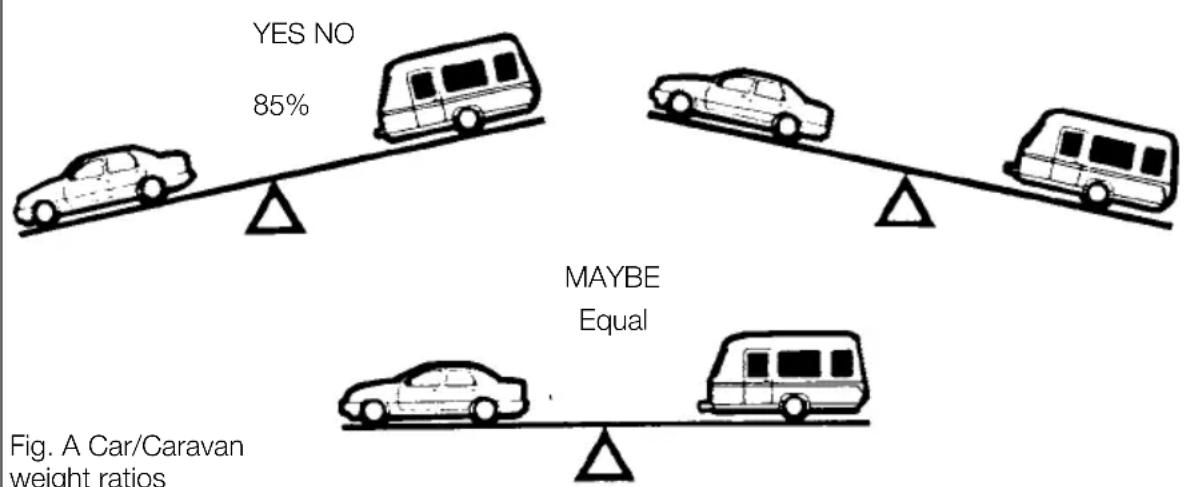
Caravan to Towing Vehicle Weight Ratio:
The towing vehicle to caravan weight ratio can be determined by calculation and is equal to:
Actual laden weight of caravan
x 100%
Kerb weight of towing vehicle
The law requires that caravans & their towing vehicles & the loads they carry must be in such a condition that no danger or nuisance is caused.
(Regulation 100 of the Road and Vehicles [Construction and Use] Regulations 1986).
Note: The towing vehicle manufacturer's limit is, in some cases, less than the kerb weight.
Mass in Running Order:
Caravanners can use a public weigh bridge to establish the mass in running order.
Note: Weigh bridges have varying weight tolerance levels.
Maximum Permissible Towing Mass:
The weight defined by the vehicle manufacturer as being the maximum that the vehicle is designed to tow at.
Train Weight (Combination Weight):
The maximum combined weight of the towing vehicle and trailer combination as specified by the towing vehicle manufacturer.
Measurement of nose weight
Nose weight may be measured using a propriety brand of nose weight indicator. Such equipment is obtainable at your Caravan Dealer.
Note: These indicators have a varying tolerance level and may not be accurate.
Another simple method is to use bathroom scales under the coupling head with a piece of wood, fitted between the coupling head and the scales, of such length that the caravan floor is horizontal with the jockey wheel raised clear of the ground. (Fig. A)
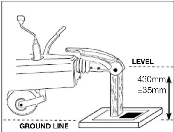
Fig. A Measuring nose weight
Nose weight can be adjusted simply by distribution of weights in the caravan.
Always lower jockey wheel before entering the caravan and then raise before measuring again. (See Loading).
Note: The height of the towball on the towing vehicle, when laden, is also critical.
⚠ WARNING: Do not lift the coupling head by hand when hitching the caravan to the car. Always raise and lower the coupling head by winding the handle on the jockey wheel up and down.
Driving licence
In order to be able to tow a caravan a driver must hold a Category B licence.
If you passed your car test before 1 January 1997 you are generally entitled to drive a vehicle and trailer combination up to 8.25 tonnes maximum authorised mass (MAM)
If you passed your driving test after 1 January 1997 and have an ordinary category B licence, you can:
- Drive a vehicle up to 3.5 tonnes or 3,500kg MAM towing a trailer of up to 750kg MAM
- Tow a trailer over 750kg MAM as long as it is no more than the unladen weight of the towing vehicle (with a combined weight of up to 3,500kg in total)
From 19 January 2013, drivers passing a category B licence can tow:
- Small trailers weighing no more than 750kg
- Trailers weighing more than 750kg, where the combined weight of the towing vehicle and the trailer is not more than 3,500kg MAM
If you want to tow a trailer weighing more than 750kg, when the combined weight of the towing vehicle and trailer is more than 3,500kg, you will need to pass a further test to obtain a B+E category licence.
Glossary & checklist
Awnings - Can consist of just a simple top sheet but may extend to a five sided frame tent attached to the side of the caravan.
Fire blanket - approved to BS 6575 is ideal for dealing with 'fat pan' fires.
Fire extinguisher - It is strongly recommended that a fire extinguisher is carried in the caravan. (For suitable types see Safety and Security).
Gas bottles - Bottled L.P. gas is the most convenient portable source of fuel. Two bottles are required for a constant supply.
An initial deposit is payable on each cylinder. We recommend the use of 6kg Calor Light Propane bottles. One position for use and one for storage only. (For detailed information see Services - Gas).
Jack - A suitable jack is essential (screw, scissor, side mounted or air jack type). Many car jacks are unsuitable. Ensure the lifting capacity of the jack is suitable for your caravan.
Levellers - Levellers help level the caravan from side to side before unhitching. Proprietary products can be purchased from your caravan dealer and need to be positioned as indicated by a spirit level.
Spare Wheel - It is always advisable to carry a spare wheel with your caravan.
Spirit Level - A spirit level is extremely useful when siting the caravan.
Stabiliser - Stabilisers help to dampen the side to side movement of the caravan.
Torque Wrench - A torque wrench is the only way that the exact recommended torque can be achieved for wheel nuts and bolts. (See Preparing for the Road).
Towing Bracket - Never use cheap alternatives, obtain one manufactured by a reputable company complying with the relevant standards.
USEFUL ITEMS
Any light passenger vehicle registered in the UK on or after August 1st 1998 will require a type approved towbar and towball (to 94/20/EC). Failure to fit a homologated towbar and towball could result in a prosecution and invalidation of your insurance cover. Always check with your car manufacturer or towbar manufacturer if in doubt.
Wooden Blocks - Wooden blocks typically 25cm square and 2cm thick are ideal for placing under corner steadies and jockey wheel when the ground is uneven or soft.
Water Containers - Two containers are required, one to carry fresh water to the caravan and one for waste water, which needs to be disposed of properly. Several types are available including jerry cans, Aquarolls, wastemaster, etc.
13 Pin Socket - One socket fitted to the car to accept corresponding plugs from the caravan this energises the road lights and caravan auxiliary circuits.
12 Volt Battery - A deep cycling, heavy duty rechargeable leisure type battery should be purchased to provide back-up power for lights and other electrical appliances. (See Battery). The securing arrangements for the battery compartment require a leisure battery complying with EN 60095-2 in particular those with ledges for fastening to the lower edge of the long sides. The maximum battery size that can be fitted is 225mm high, (including terminals) x 175mm deep x 353mm wide. The depth and width dimensions include the rim around the bottom used for securing the battery.
Note: Batteries that are not foot mounted, ie. without a rim, can still be fitted, but check first that they will fit within the battery box and can be secured before purchasing.
⚠ WARNING: Your caravan dealer should be consulted if additional equipment is to be fitted as strong points may or may not be provided in the design.
Caravan motor movers
The design and fitment of a caravan motor mover shall be in accordance with the NCC Code of Practice 305 and you should ensure you receive a signed installation certificate of compliance from the installer.
Failure to do so may invalidate you warranty.
Note: Fitting additional equipment, such as a motormover will reduce the caravan allowable payload.
Note: The fitting of a motormover may require a larger capacity battery fitting.
Note: If a towing cover is fitted, care should be taken not to obscure lights, reflectors and protect against rubbing or damaging the bodywork.
Useful memory aid
Car
External mirrors
Fire extinguisher
Jack
Petrol can
Spare bulbs
Spare keys
Spare wheel
Tool kit
Towball cover
Tyre pressure gauge
Warning triangle
Tyre Pump
Caravan
Awning pegs and poles
Awning ground sheet
Bucket
Corner steady brace
Corner steady pads
Coupling lock
Door mat
Fire blanket
Fire extinguisher
Fresh water container
Gas cylinders
Jack
Levelling boards
Mallet
Site/caravan mains lead
Spare bulbs -
(Mandatory in E.C.)
Spare 12v fuses
Spare high pressure gas hose
Spare wheel
Spirit level
Toilet fluid
Waste water container
Wheel brace
Personal
After sun cream
First Aid Kit
Flannels
Hairbrush and comb
Make up. etc.
Raincoats
Toothbrush
Toothpaste
Scissors
Shampoo
Shaving kit
Shoe cleaning kit
Soap
Sun tan oil
Wellington boots
Domestic
Adhesive tape
Air freshener
Aluminium foil
Ashtrays
Bedding
Bin liners
Binoculars
Bottle opener
Breadboard
Brush and dustpan
Butter dish
Camera
Carving knife
Chairs
Clock
Clothes brush
Clothes line
Coat hangers
Coolbox
Colander
Crockery
Cruet
Corkscrew
Cutlery
Dish cloth and brush
Dusters and polish
Disposable cloths
Egg cups
Floor cloth
Fly spray
Food
Food mixer
Frying pan
Glasses
Grill pan
Jugs
Kettle
Kitchen roll
Kitchen tools
Matches
Measuring jug
Milk jug
Mixing bowl
Needles and thread
Oven gloves
Pegs
Piezo Gas lighter
Potato peeler
Radio
Rubbish bin
Saucepans
Scissors
Sieve
Sugar bowl
Shopping bags
Sleeping bags
Tea pot
Tea strainer
Tea towels
Table cloths
Table mats
Television
Tin opener
Tissues
Toilet paper
Torch
Towels
Toys & Games
Vacuum cleaner
Washing up bowl
Documents
Bank and credit cards
Caravan Certificate
Cheque book
CRIS document
Driving licence
Green Card
Insurance (some Euro
countries)
Maps and guides
Money
MOT Certificate
Vehicle Registration
Documents
PREPARING FOR THE ROAD
Preparing for the road
Pre-load checklist
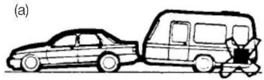
⚠ WARNING: Never enter the caravan without first lowering the four corner steadies with the brace provided.
Before loading check:
- loose articles are stowed securely. Do not stow tins, bottles or heavy items in overhead lockers prior to towing.
- all lockers and cupboard doors are closed and secured, including the bathroom door.
- all bunks are secure.
- ensure shower door is secure
- all rooflights are closed and secured.
- main table is stored in its transit position.
- television aerial is lowered
- fridge is on 12V operation and door lock is set.
- all windows are fully closed and latched. Never tow with windows on night setting. Leave all curtains and blinds open to aid rear visibility.
- gas cylinders are correctly positioned, secured and turned off, unless using en route heating.
- battery is secure and mains connecting cable is disconnected and stowed.
- Ensure control panel settings are correct for 12v fridge operation. See control panel instructions for detail.
⚠ WARNING: Turn off gas appliances except en route heating (if fitted).
⚠ WARNING: Do not travel with televisions or microwaves in overhead lockers unless the appliance was supplied fitted to your caravan by the manufacturer.
⚠ WARNING: Always disconnect the electrical connector between the towing vehicle and the caravan before connecting a LV supply to the caravan.
natural_image
Line drawing of a car and a van with a person standing beside it (no text or symbols)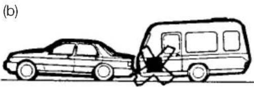
natural_image
Line drawing of a car and a van with a person inside, no text or symbols present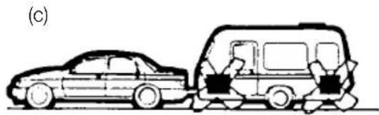
natural_image
Side view of a car and a van in motion, no text or symbols visible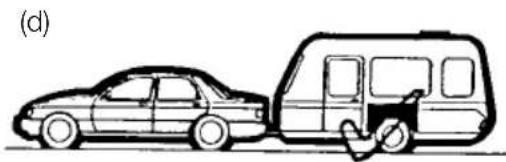
natural_image
Line drawing of a car and a van side by side, no text or symbols presentFig. A Loading your caravan
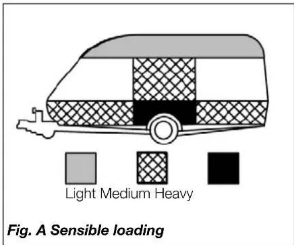
How to apportion it
- Load heavy items low down near the floor and mainly over or just in front of the axle(s) (Fig. A).
- Load evenly right to left so that each caravan wheel carries approximately the same weight.
- Do not load items at the extreme front or rear since this can lead to instability due to the 'pendulum effect'.
- Load remainder to give a suitable nose weight at the towing coupling.
Check nose weight.
Note: Do not overload car boot.
⚠ WARNING: All heavy and/or voluminous items (e.g. TV, radio etc) must be stored securely before travelling.
⚠ WARNING: Please take care to ensure that you have allowed for the masses of all items you intend to carry in the caravan. e.g. optional equipment, and personal effects such as clothing, food, pets, bicycles, sailboards, sports equipment etc.
⚠ WARNING: under no circumstances should the MTPLM of this caravan be exceeded
Towing vehicle's rear suspension
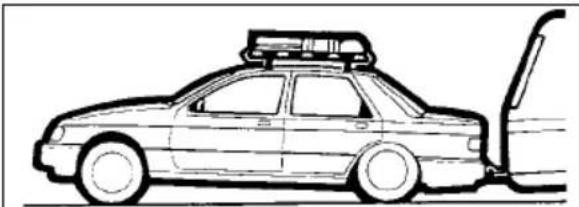
It is important that the towing vehicle's rear suspension is not deflected excessively by the nose weight on the tow ball. If it is excessive the steering and stability will be affected. (Fig. B)
The greater the towing vehicle's tail overhang (the distance between the rear axle and the tow ball), the greater the effect the nose weight will have on the towing vehicle's rear suspension.
natural_image
Line drawing of a car with roof-mounted equipment and exhaust pipe (no text or symbols)Fig. B Illustration of excessive deflection of vehicle's rear suspension
After trying out the caravan it may be found that a stiffening of the rear suspension is necessary - but note that this may give the towing vehicle a firmer ride when not towing.
There are a number of suspension aids available and advice should be sought on which to use and how to fit. It is important to ensure that the caravan is towed either level or slightly nose down.
If you have any doubts about the suitability of your towbar for towing a caravan consult the towing bracket manufacturer.
Do not exceed the:
• Gross Vehicle Mass (G.V.M. on car plate).
• Maximum Technically Permissible Laden Mass (M.T.P.L.M.) on the caravan.
- Gross Vehicle Combination Mass (Train Weight) (G.V.C.M. on car plate).
• Maximum Permissible Towing Mass.
• Vertical Static Load on the caravan coupling (noseweight).
- Maximum Vertical Load on the car towball as specified by towing vehicle manufacturer (noseweight).
- Driving licence limitations
STABILITY
Stability
All our models are of a well balanced design and should be exceptionally good towers. All models apart from the Sprite range (Diamond pack option) have an AL-KO stabiliser fitted as standard. The common causes of poor stability include:
a. Worn springs or loose spring fixings on the towing vehicle.
b. Towing vehicle springs too soft.
c Insufficient nose weight.
d Nose of caravan is towing too high.
e Unsuitable towing vehicle
Galvanised steel chassis
Drilling of the galvanised steel chassis will invalidate the warranty and must not be done.
Towball
The AL-KO stabiliser is designed to be used with a swan neck, fixed or detachable towball. If you use a ‘bolt on type’ towball you may need to replace your towball with a special extended neck towball.
If you have a bolt on type towball you should ask your dealer to check clearance around the towball to allow for the stabiliser to articulate.
The AL-KO extended neck towball (available from your dealer) is approved and marked with the approval number EC94/20. Failure to provide enough clearance around the towball may invalidate your stabiliser warranty.
Stabiliser friction pads
The AL-KO stabiliser uses ‘friction pads’ inside the coupling head to clamp the towball. These pads must be kept free from grease and contamination from the towball.
The friction pads should last approximately 50,000km (30,000 miles) under normal use, if correctly maintained.
Suitable towing vehicles
The caravan is manufactured for towing behind normal road cars and is not suitable for towing behind commercial vehicles. It is strongly recommended that whenever a caravan is to be towed over rough terrain, e.g. a field or track, great care should be taken to ensure that no undue stress is placed upon the caravan via the hitch mounting, i.e. reduce speed. If in doubt, please consult the chassis manufacturer and the towing vehicle manufacturer who will advise. Touring caravans based on standard AL-KO chassis can be towed by four wheel drive off road leisure vehicles providing the unit is used to tow in a like manner to a conventional road-going car and driven in the same considered manner.
Towbar manufacturers should be consulted before towing an uncompensated twin axle caravan.
Snaking
This is a term used to denote an unstable car and caravan combination where the caravan 'weaves' from side to side often causing a similar swaying movement in the car itself.
Causes:
- Unsuitable or unbalanced outfit.
- Incorrect loading or weight distribution.
- Excessive speed especially downhill.
- Side winds.
- Overtaking.
- Being overtaken by a large fast moving vehicle.
- Erratic driving.
- Insufficient tyre pressures, car and caravan
- Incorrect vehicle towball height
- Worn stabiliser pads or towball
Cures
Cases of persistent snaking can be alleviated by the use of a stabiliser.
On the road
If you do find your outfit snaking, try to keep the steering wheel in a central position as far as possible, decelerate and avoid braking if possible.
Types of tyres fitted
The original tyres fitted by the manufacturer are suitable for towing at a maximum speed of up to 81 mph (130 kph).
Tyres
Caravan manufacturers choose the type, size, profile, load carrying capacities and speed ratings to match the design masses of there vehicles, adjusting the tyre pressures to suit. Only change the type of tyres on your caravan on expert advice from the caravan manufacturer, or tyre manufacturer.
Tyre maintenance
Tread depth
Pay special attention to the amount of tread remaining on your tyres, and measure them regularly. Always replace tyres before they reach the minimum legal limit of 1.6mm. Periodically tyres should be rotated to equalise wear in the same manner as car tyres.
Pressures
The caravan manufacturers plate (fixed adjacent to exterior door) and Technical handbook contains information about caravan loading and the required adjustments to tyre pressures, which should be followed for safety (these pressures relate only to the tyres originally fitted to the caravan). Tyre pressures should always be checked and corrected prior to each journey. It is vital that tyre pressures are maintained at the levels recommended by the manufacturer to ensure maximum tyre life, safety and handling characteristics.
Over or under-inflating tyres is likely to seriously impair their performance and may compromise the safe use of the vehicle.
Over-inflation increases overall tyre diameter, decreases the amount of tread in contact with the road, decreases sidewall flexibility and affects road-adhesion.
Under-inflation decreases overall tyre diameter, increases sidewall flexing, generates higher tyre operating temperatures and difficult vehicle handling characteristics. Running an under-inflated tyre may cause premature tyre failure. Both over and under-inflation adversely affect tyre life.
Tread
Keep tyre treads clean of stones and other foreign bodies, and check regularly for damage to the tread and sidewalls. It is vitally important that any damage is checked out by a tyre expert and any necessary repairs or replacements are carried out immediately.
Tyre valves
Check tyre valves carefully. Ensure the caps are in place free from dirt/ debris and that there is no evidence of cracking or damage to the valve stem.
Tyre aging
Rubber compounds used in tyres contain chemicals that help to slow down the natural aging process of untreated rubber. However, tyres do deteriorate with age, which increases the risk of tyre failure, and there are many ways in which this can be spotted:
- Cracking/crazing on the side wall of the tyre, caused by its flexing
• Distortion of tyre tread - Deformation of the carcass of the tyre
There will also be a deterioration of the ride quality caused by vibrations through the tyre. This may signify the tyres performance has been affected by age and should be investigated as soon as possible
Note: It is recommended that tyres are replaced after 5 years from the date of first inflation. The date of first inflation is normally within a few days of the date of manufacture of the vehicle they are fitted to, and this date can be determined from the gas and / or electrical certificate supplied with the caravan.
We recommend that tyres that are over 5 years old (from first inflation) are inspected and passed as fit for use by a qualified technician. It is possible that in the event of a tyre failure, an insurer may not cover any losses incurred if the tyre is over 5 years (from first inflation) and was not inspected no more than 12 months prior to the incident.
THE TYRE LAW
Tyres that display signs of aging should be removed and not put to further use.
The effects of aging can be brought about prematurely in several conditions. Tyres fitted as spare wheels may age prematurely. If tyres on caravans are not in regular use they should be inspected before every journey, several cleaning products may also harm the chemicals in the rubber. However, the age of a tyre will affect its safety and increase the risk of failure, and you should inspect tyres for the signs of aging regularly.
Note: The use of some motor movers can damage or increase wear on the tyres prematurely.
The tyre law
Note: Sales literature/ Technical Handbooks publish recommended tyre pressures for the MTPLM only (fully laden condition). It is not possible to publish tyre pressures for any other load condition other than the MTPLM.
Tyre types
It is illegal to mix tyres of a different construction on the same axle.
Note: Although the caravan may be fitted with the same type of tyre as the towing vehicle, the pressures specified are different. All charts show values for cars and are therefore not applicable for caravans.
Pressures displayed on tyre walls apply ONLY in North America and Canada.
Wheels
Caravan wheel bolts supplied with your caravan should be tightened to a torque of 88Nm (65lb/ft) on steel wheels or 130Nm (96lb/ft) on alloy wheels and should be checked with the use of a torque wrench regularly. Only use a spare wheel and tyre of the type and size provided with you caravan.
Note: Please remember to check the wheel bolt torque setting regularly.
Wheel rims
Two sizes of wheel rims are used 5.5J x 14 and 6J x 15, the rim sizes are the same for both steel and alloy rim, incorporating a double safety hump which conforms to European safety standards. Check the size on your caravan before replacing a rim.
PRE-TOW CHECK LIST
Hitch head load capacity
The maximum vertical static load which can be put upon the hitch head when connected is 100kg. Please refer to the technical data in your handbook. (But see also vehicle manufacturer's weight limits on towball loading.)
Pre-tow checklist and hitch-up for AKS 3004 stabiliser
natural_image
Person working on a white car under maintenance, no visible text or symbolsCheck gas locker, battery locker and cassette toilet doors are secure.
Check wheelnuts, tyre pressures and tyre conditions.
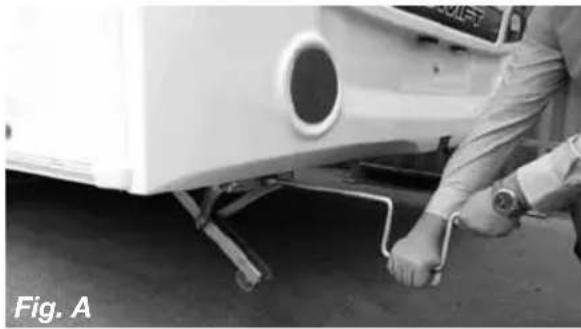
Fully raise all four corner steadies. (Fig. A).
Pick up any levelling pads or levelling boards.
Check: rooflights/vents are securely closed.
Ensure television aerial is lowered.
Switch off gas supply and change over to 12v electricity if required.
Lock the caravan exterior door.
natural_image
Close-up of a car being charged with a tool, no visible text or symbolsAn assistant can help in the hitching operation by standing on the left hand side of the drawbar (facing rear of car) and extending an arm horizontally to indicate position of the coupling. When reversing aim the towball
of the car directly at the caravan drawbar. Remove towball cover and keep in car.
Adjust the jockey wheel to ensure the cup is high enough to slide over the towball.
Release caravan handbrake.
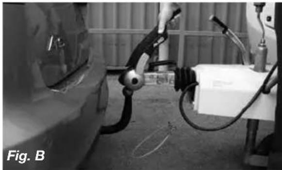
Position cup over the ungreased towball, release and lift forward the large stabiliser handle (Fig. B) lift forward the exposed smaller handle (Fig. B) until it clicks up.
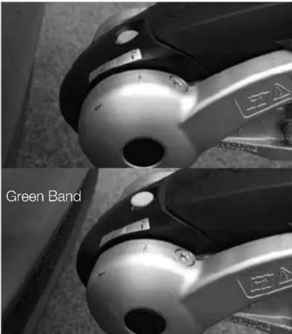
The hitch head is fitted with a visual indicator to show whether or not it is properly connected to the towball. A green band will show immediately below the red indicator button on the hitch head when a proper connection has been made. (See Fig. C)
Adjust jockey wheel to lower cup on to the ball. A click indicates it is fully engaged. Ensure the smaller handle has returned to its free position.
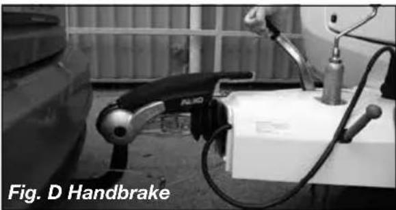
Secure caravan handbrake. (Fig. D)
natural_image
Black-and-white photo of a handbrake device with visible wiring and components, labeled 'Fig. D Handbrake' (no other text or symbols)PRE-TOW CHECK LIST
Connect breakaway cable as described on page 29.
Ensure that the jockey wheel is fully wound up and properly located in the slots in the jockey wheel tube, then release the clamp handle, lift the whole unit as high as possible ensuring the wheel is pointing directly backwards and retighten the clamp handle.
Note: Ensure jockey wheel locates in recess provided. Carelessness could result in damage to the A frame cover.
Ensure the hitch is secured by checking the visual indicator (figure C).
⚠ WARNING: If the green band is showing when the hitch head is not connected to the towball there is a fault - contact your Dealer.
Connect the 13 pin plug to car socket by inserting and rotating slightly ensuring there is enough loose cable for cornering, ensuring they won't drag on the ground.
Check all car and caravan roadlights are working. Check round the caravan for anything left behind.
Fit extending mirrors
Release caravan handbrake, adjust all mirrors from driving seat and proceed.
- All road lights must be in working order.
- Lenses and reflectors must be in good condition
- Bulbs must be of correct wattage for the application (see Service handbook).
⚠ WARNING: Do not cause any road lighting to be obscured by the addition of any options or accessories to your caravan.
13 Pin socket
Please be aware that some car manufacturers and towbar manufacturers do not wire up all 13 pins as standard, unless requested.
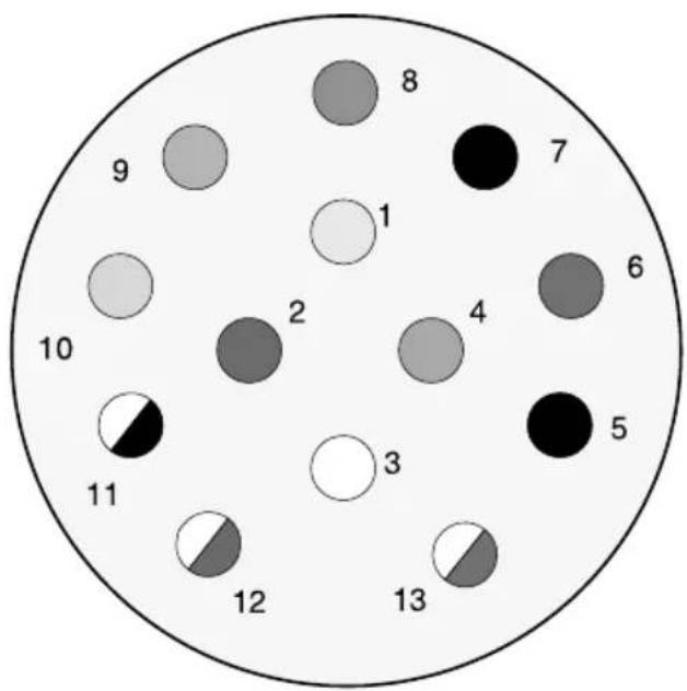
pie
| Label | Value | |---|---| | 1 | 8 | | 2 | 2 | | 3 | 3 | | 4 | 4 | | 5 | 5 | | 6 | 6 | | 7 | 7 | | 8 | 8 | | 9 | 9 | | 10 | 10 | | 11 | 11 | | 12 | 12 | | 13 | 13 |11446 Plug Connector viewed from cable entry on plug
| Pin No | Core Colour | Core Size | Function |
| 1 | Yellow | 1.5 | Left Hand Indicator Light |
| 2 | Blue | 1.5 | Rear Fog Warning Light(s) |
| 3 | White | 2.5 | Earth for pins 1 - 8 |
| 4 | Green | 1.5 | Right Hand Indicator Light |
| 5 | Brown | 1.5 | Right Hand Tail Light |
| 6 | Red | 1.5 | Brake Lights |
| 7 | Black | 1.5 | Left Hand Tail Light |
| 8 | Pink | 1.5 | Reverse Light(s) |
| 9 | Orange | 2.5 | Car +ve |
| 10 | Slate (Grey) | 2.5 | Fridge +ve |
| 11 | White/Black | 2.5 | Earth for pin 10 |
| 12 | White/Blue | 1.5 | Not Yet Allocated |
| 13 | White/Red | 2.5 | Earth for pin 9 |
TOW CAR ELECTRICS
Tow Car Electrics
In all cases, The Swift Group assumes that the tow car harness and electrics have been fitted with the specific requirement of connection to a caravan, which may contain AL-KO trailer control (ATC), a 12V powered fridge and charging circuits.
Most modern retro-fit towbars contain a relay, located somewhere within the boot of the tow car, which may have a selectable power output for the fridge supplier.
If a customer is experiencing issues with the fridge supply it is possible the relay requires adjustment and they should contact their tow vehicle electrics installer or an auto electrician to verify the installation.
LED Road Lighting
Your caravan maybe fitted with LED road lighting, including the directional indicators and stop lamps. LEDs consume very little power, offer excellent light output and longevity when compared to traditional tungsten bulbs.
Some more advanced tow cars are fitted with Vehicle Light Monitoring Systems {VLM}, where the car monitors the condition of the trailer/caravan road lights and advises the driver of any bulb failures. To do this, some tow cars expect to see a load on the caravan lighting circuit similar to a tungsten bulb while others may send a pulse of energy to each light to confirm that the resistance of a bulb is present.
The result of the above is that some tow cars may incorrectly advise the driver of a bulb failure, due to the use of LED lights while others may flash or pulse the lights during use.
Recognising this, The Swift Group have developed an additional towing fusebox, which when connected to the existing towing fusebox and is used to assist the towcar in recognising the VLM System. Depending on the type of car and system used the fusebox maybe model specific.
The secondary fusebox is chargeable and available through any Swift Group Dealer.
Note: This will change updates will be required.
Caravan 13 Pin Connection - care advice
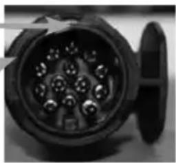
All caravans since 2008 have been supplied with a 13 pin plug to connect to the towcar. The 13 pin plug has an inner ring assembly that is independent from the outer body.
Plug Inner Ring (containing male pin terminals) - fitted to the caravan
Plug Outer Body with locating groove and hood - fitted to the caravan
Socket Body (containing female socket terminals) - fitted to the car
natural_image
Close-up of a black electrical connector with multiple pins (no visible text or symbols)Under normal circumstances the inner ring and the outer body will be locked in one position (see fig 1).
Fig 1
natural_image
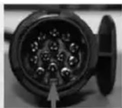
Close-up of a black electrical plug socket with multiple pins, no visible text or symbolsCorrect alignment
When the plug is first inserted in the socket body ensure that the locating protrusion (key) matches the groove (keyway) in the socket body. The outer body can then be rotated a full 90 degrees clockwise until a click is felt or heard, at this point the cover flap can be allowed to fall over the circular surface of the plug top.
To remove the plug it is important to rotate the outer body a full 90 degrees anti-clockwise, again until a click is heard or felt before withdrawing the plug from the socket. This will ensure that the inner and outer parts of the plug are returned to a locked condition.
⚠ WARNING: If the connector is not fully rotated anti-clockwise prior to removing it from the socket it is possible that the inner ring will become 'floating' and may result in a condition where the protrusion will be incorrectly aligned (see fig 2 & 3).
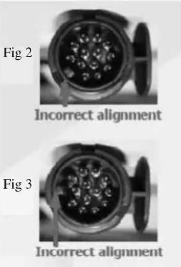
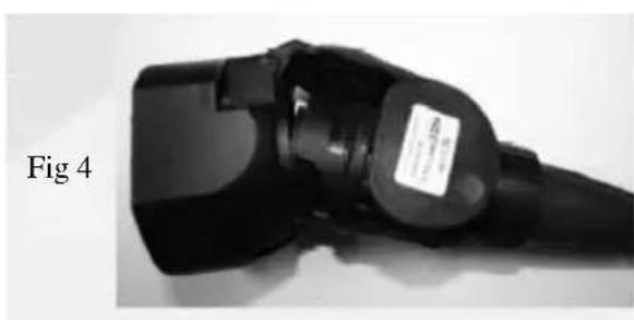
If this situation does occur then it can be corrected by entering the edge of the protrusion on the plug into the groove in the socket (see Fig 4) and rotating the plug body anti-clockwise until a click is felt. This process will re-establish the lock between the inner and outer parts allowing the correct insertion of the plug into the socket.
natural_image
Close-up of a black electric vehicle charging plug (no visible text or symbols)Note: Customers should note that the towbar and towcar electrical socket will be checked from the 1st January 2012 as part of the standard MOT regulations, under directive 2009/40/EC. This not only applies to tow cars but also all Motorhomes fitted with a tow bar and socket. Inappropriate repair or modification to either maybe deemed a failure of the vehicle if it is likely to affect the road worthiness of the vehicle.
Passengers
Passengers are forbidden to ride in a caravan.
Breakaway cables
UK law requires that all caravans are fitted with a safety device to provide protection in the unlikely event of separation of the main coupling while in motion. A device referred to as a 'breakaway cable' fulfils this requirement and when fitted as on your caravan is mandatory.
Purpose
To apply the caravans brakes if it becomes separated from its towing vehicle. Having done this, the cable assembly is designed to part allowing the caravan to come to a halt away from the towing vehicle.
Identification
A thin steel cable with a red plastic coating fitted with a means of attachment for connection to the towing vehicle. Located directly beneath the coupling head.
Operation
In the event of the main coupling of the caravan separating from the towing vehicle, the cable should be able to pull tight, without any hindrance, engaging the caravan brakes. The breakaway cable should not become taut during normal driving.
Correct procedure for use
Regularly check the cable and clip for damage. If in doubt contact your Swift Group dealer.
Make sure the cable runs as straight as possible and goes through the cable guide
BREAKAWAY CABLE
fitted underneath the caravan coupling head.
Determine whether or not the towing vehicle towbar has a designated attachment point (i.e. a part specifically designated for a breakaway cable).
Where a point is designated on the towbar:
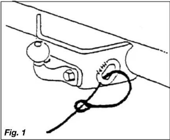
- Pass the cable through the attachment point and clip it back on itself (figure 1).
natural_image
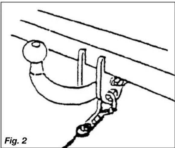
Line drawing of a mechanical clamp or bracket with a rope and bulb, labeled 'Fig. 1' (no text or symbols on the diagram itself)- Do not clip directly onto the designated point (figure 2) since the clip is not designed for use in this way.
natural_image
Diagram of a cable or wire connection with a curved cable and attached clamping device, labeled 'Fig. 2' (no text or symbols on the diagram itself)Where there is no designated attachment point on the towbar:
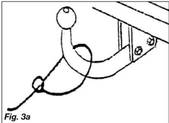
- Fixed ball: Loop the cable around the neck of the towball in a single loop only. See figure 3A and 3B.
natural_image
Simple line drawing of a rope tied to a curved pipe with a spherical object, labeled Fig. 3a (no text or symbols on the diagram itself)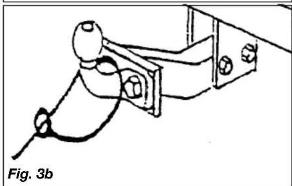
natural_image
Technical line drawing of a mechanical assembly with no visible text or symbols- Detachable towball: You must seek guidance on procedure from the towing vehicle towbar manufacturer or supplier.
When the breakaway cable is attached, check:
a. that the cable cannot snag in use on the caravan coupling head, jockey wheel, stabiliser or accessory e.g. bumper shield, cycle carrier etc.
b. that there is sufficient slack in the cable to allow the towing vehicle and caravan to articulate fully without the cable ever becoming taut and applying the brakes.
c. that it is not too slack and can drag on the ground. If left loose, the cable may scrape along the ground and be weakened so that it subsequently fails to do its job. The cable may also be caught on an obstacle when in motion thus engaging the caravan brakes prematurely.
Mirrors
The driver of the towing vehicle must have an adequate view of the rear.
If there is no rear view through the caravan it is essential that additional exterior towing mirrors are fitted. This is mandatory in some European countries and drivers can face instant fines if extension mirrors are not fitted.
⚠ WARNING: Any rear view mirror must not project more than 250 mm outside:
a. the width of the caravan when being towed.
b. the width of the towing vehicle when driven solo.
Note: Any rear view mirror fitted shall be 'e' marked and cover the field of view as stipulated by type approval requirements (Community Directive 2003/97 or 2005/27 or ECE Regulation 46.02 or Regulation 33 of the Road Vehicles (Construction & Use Regulation 1986).
Moving off
Let the clutch in smoothly.
Allow more engine speed to produce the power to move the additional weight of the caravan.
Reduce wear and tear on clutch and transmission by taking extra care.
Change gears smoothly.
Try not to jerk the clutch.
Reversing
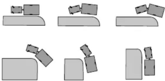
When the towing vehicle is reversing, the overrun device shaft is pushing in, applying the brakes via the overrun lever, brake rod system, bowden cables and the expander mechanism.
natural_image
Six abstract geometric shapes with gray blocks and rectangles, no text or symbols presentFig. A Reversing
The backwards rotation of the brake drum causes the secondary brake shoe to collapse cancelling out the braking effect, allowing the caravan to move backwards. At the same time the transmission lever swings back and compensates for the entire travel.
When reversing up a slope or on a loose surface the brakes may apply themselves, Correct maintenance and set up of the brakes will help prevent this. Incorrect adjustment of the wheel brakes or linkages will result in making reversing difficult.
Proficiency at reversing can only be achieved with practice and should be first attempted in a large open area (Fig. A).
Speed limits
Normal road towing: 50mph
Motorways (including dual carriageways): 60mph
CARAVAN HANDLING
Caravan handling
Allow for caravan being wider than car.
Do not bump kerb with caravan wheels.
When passing other vehicles allow more than the normal clearance for driving solo.
Allow longer to get up speed to pass.
Allow for the outfit being twice its normal length.
Do not suddenly swing out.
Carry out all manoeuvres as smoothly as possible.
Use nearside wing mirror to check caravan has cleared when overtaking.

WARNING: Take care not to foul or bound caravan chassis whilst traversing mps or other obstacles.
Motorway driving
Important points
-
Caravans may not be towed in the outside lane of a three or four lane motorway. (Reg. 12(2) of the Motorway Traffic [England and Wales] Regulations 1982).
-
Reduce Speed:
a. In high or cross winds
b. Downhill
c. In poor visibility
- High sided vehicles cause air buffeting so extra care must be taken when passing or being passed. As much space as possible should be given.
ALKO Spare wheel carrier tips
The caravan needs to be jacked to the maximum lifting height to be able to withdraw the wheel from the carrier.
Note: The side-lift jack has a maximum lifting height of 375mm and the scissor jack a maximum lifting height of 340mm.
Customers should also ensure that the telescopic arms are kept well greased at all times to guarantee ease of operation.

WARNING: If it becomes necessary completely remove the carrier from the chassis remember that the washers and it pins are on the inside of the chassis as well as the outside.
Note: On some models the spare wheel is located in either the gas locker or under the fixed bed.
Changing a wheel
- Leave caravan hitched to towing vehicle and ensure that the caravan and towing vehicle handbrakes are applied.
- Lower corner steadies (as safety measure) on the side that is being jacked up.
- Remove wheel trims (if fitted).
- Use wheel brace to slacken off wheel nuts on the wheel to be changed.
- Position jack under the axle at the appropriate jacking point (see Fig. B, page 34)
- Jack up the caravan until the wheel for removal is just off the ground.
- Remove the wheel nuts and remove the wheel.
- Fit spare wheel and reverse the above procedure. Ensure clean, dry mating surfaces and clean, dry bolt/nut sealing areas.
- Ensure the spare wheel is free from damage and distortion
- Tighten all five bolts, according to Fig. A, to 88Nm (65lb/ft) for steel wheels or 130Nm (96lb/ft) for alloy wheels using a torque wrench or have checked as soon as possible. Ensure the correct wheel fixings are used, as supplied with your caravan.
⚠ WARNING: When a wheel has been removed and replaced the torque of the wheel nuts should be re-checked after approximately 50 miles.
Wheel bolt tightening
When refitting a wheel it is ESSENTIAL that the wheel bolts are tightened to the recommended torque figure and in the correct sequence.
Note: Only use a suitable wheel brace to loosen and tighten the wheel bolts. Do not use the corner steady brace for this application.
The sequences necessary to correctly carry out this work on a 5 stud wheel is as follows:
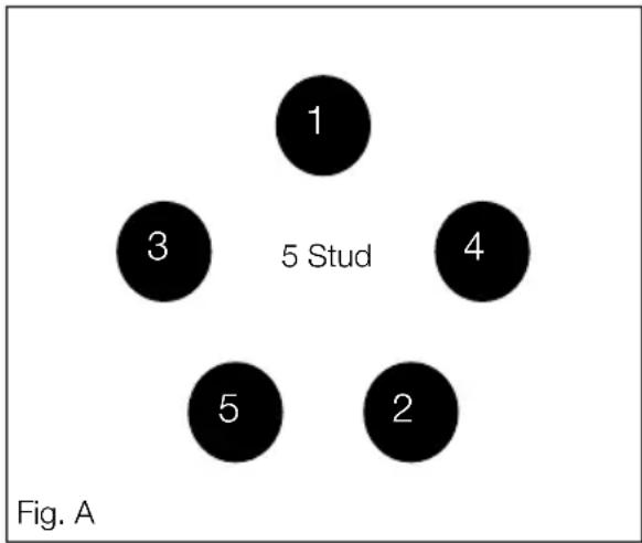
Please note the correct torque settings.
Jacking points
⚠ WARNING: Only jack up your caravan when it is coupled up to the car with its handbrake applied and in 1st gear (engine off).
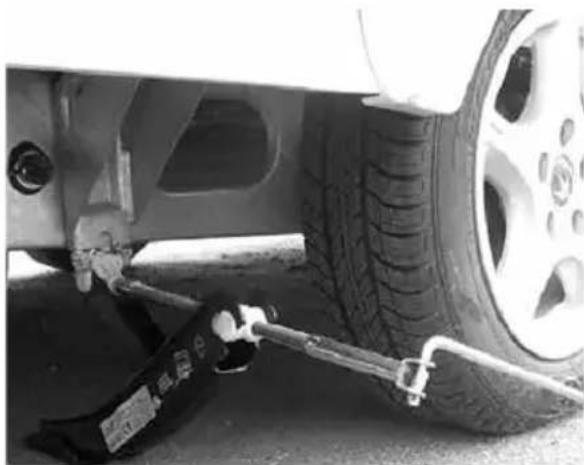
Ensure that the jack is located in the correct position, i.e. on the jacking bracket on the chassis for the AL-KO side mounted jack (Fig.B). Alternatively the reinforced axle mounting plate can be used as an alternative but the chassis member itself MUST NEVER be used as a jacking point.
All caravans are provided with the facility to fit AL-KO side jacking points and although a scissor, trolley or bottle jack may be used.
Ensure the lifting capacity of your jack is suitable for your caravan.
STOPPING ON A HILL
natural_image
Close-up of a car tire and suspension system with visible hoses and components (no text or symbols)Fig. B Side lift jack
Stopping on a hill
Pulling off again can sometimes present a problem. The easy solution is
- Carry a good sized wedge shaped piece of wood with a rope or light chain attached.
- Attach the other end of the rope to the nearside rear grab handle.
- Place the wood behind the nearside caravan wheel.
- Carefully reverse the car slightly back down the hill, the caravan will stop against the wedge and turn.
- Drive forward since this attempt to move up the hill will now not involve pulling the full weight of the caravan until the car has gained some traction.
- When reaching the top of the hill retrieve the wedge.
Arrival on site
Note: Check and observe site regulations.
Manoeuvring your caravan by hand
Note: Care must be taken when manoeuvring your caravan into position. Pressure placed on unsupported parts of front and rear GRP/ ABS panels may cause surface damage/ cracks to appear. Use the grab handles provided.
1. Selecting a pitch
Do not pitch in such a position that your outfit will obstruct others coming in.
Try to choose an area which is dry, reasonably level and preferably with a hard base.
If you have no alternative but to pitch on a slope ensure that, for when you leave, you are facing down the slope.
It is good practice to chock the wheels of the caravan when parked on a slope even though the caravan brakes are applied.
2. Levelling the caravan
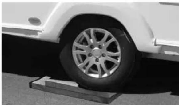
Levelling must be carried out in both directions in order for the refrigerator and other equipment to function correctly. This should be done before unhitching the caravan. Levelling boards (Fig. C) can be used to raise one side of the caravan by driving or reversing the caravan onto the boards. Apply the handbrake and chock the wheels.
The positioning of the jockey wheel can be used to help level the caravan.
Lower the corner steadies until they are in firm contact with the ground.
⚠ WARNING: DO NOT use the steadies as a jack they are only a means of stabilising the caravan.
Levelling pads or boards should be used under the steadies where the ground is soft or uneven.
In extreme cases where it is necessary to raise a wheel off the ground for levelling purposes, further adequate support should be applied so that the steadies do not take any undue strain.
natural_image
Close-up of a car wheel rim mounted on a wooden platform, no visible text or symbolsFig. C Levelling board
Exterior door
To prevent distortion of the body, the caravan must be always correctly sited and levelled. Failure to site the caravan correctly may prevent the exterior door from closing properly.
3. Unhitching
Before applying the handbrake ensure the hitch is fully extended and not compressed behind the tow vehicle otherwise the hitch will not release from the tow ball.
Apply the caravan handbrake.
Lower the jockey wheel to the ground.
Disconnect the breakaway cable and road lighting plugs.
AKS 3004
Release the stabiliser by lifting the large handle. Then lift the exposed small handle forward until it clicks up, at the same time winding down the jockey wheel, to lift the caravan clear of the towing vehicle.
SAFETY AND SECURITY
Fire 38
SI 601 Smoke Alarm Operation 38
Alarm Test 39
Fire extinguisher 40
Escape paths 40
Children 41
CO Alarm - Fireangel CO-9X Carbo Monoxide Alarm operation 41
Ventilation 48
Security 48
AL-KO secure immobiliser 49
Tracker 50
Mobile Alarm System 51
FIRE AND FIRE ALARM
Fire
Important: Your attention is drawn to the notice affixed inside the caravan wardrobe advising on fire precaution, ventilation and what to do in case of fire.
In case of fire
- Get everyone out of the caravan as quickly as possible using whichever exit is the quickest, including windows. Do not stop to collect any personal items.
- Raise the Alarm. Call the Fire Brigade.
- Turn off the gas supply valve if it is safe to do so.
- Turn off the electricity supply at supply point.
Model-si 601 smoke alarm operation
Normal condition
The red LED on the front should flash once every 40 seconds to show the alarm is active.
Low Battery Condition
Important: Your smoke alarm requires a battery with a sufficient capacity of power to operate correctly. This must also be correctly installed.
Should your smoke alarm enter a low battery condition, the unit will emit an audible ‘chirp’ once every 40 seconds. When this occurs you must replace the battery immediately. Your smoke alarm will continue to warn of this low battery condition for at least 7 days, however, failure to change the battery after this time would mean your smoke alarm has insufficient power to alert you in a real fire situation.
Battery replacement
Important: Only the following batteries can be used for replacement. Use of a battery other than those recommended below may have a detrimental effect on the detector's operation. Use of a lithium (long-life) battery could provide power for 10 years under normal operating conditions, meaning there is no need for an annual battery change.
Note: The alarm cover can't be installed without a battery fitted.
Note: Upon delivery the battery may be fitted with a protective cover. Please ensure this is removed before use.
Carbon-Zinc type:
Eveready Energizer 1222;
Gold Peak 16045 (UL).
Alkaline Type:
Energizer 522; Duracell MN 1604; Duracell 9V Ultra; Energizer 9V Ultra+; Gold Peak 1604A.
Lithium (long life) type:
Ultralife U9VL
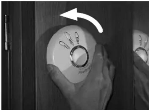
- Remove the alarm from its mounting plate by turning anti-clockwise
natural_image
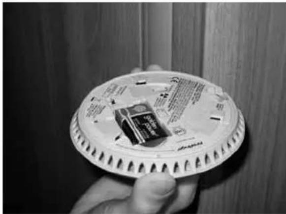
Close-up of hands holding a circular device with a ring, showing a curved arrow pointing to its top (no text or symbols visible)- Remove the existing battery and replace with a new battery. From the above list making sure that the positive and negative connections are in the correct position. If unsure see the alarm user manual.
natural_image
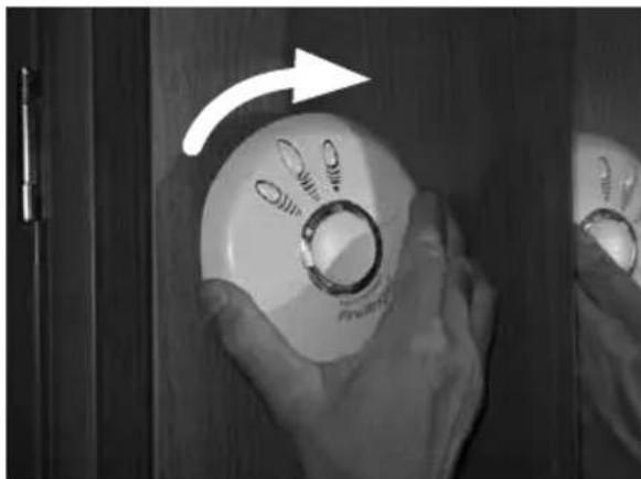
Hand holding a plastic cup with printed cards, against a wooden wall (no visible text or symbols)- Replace the alarm on its mounting plate, lining up the large central vent on the front of the alarm, with the 'X' that is moulded into the plastic on the mounting plate (if unsure see page 13 of the alarm user manual). Ensure the unit is securely fitted.
natural_image
Close-up of hands holding a CD/DVD device with a white circular dial and ring, no visible text or symbols- Test your alarm as explained in the next section 'Alarm Test'.
Alarm test
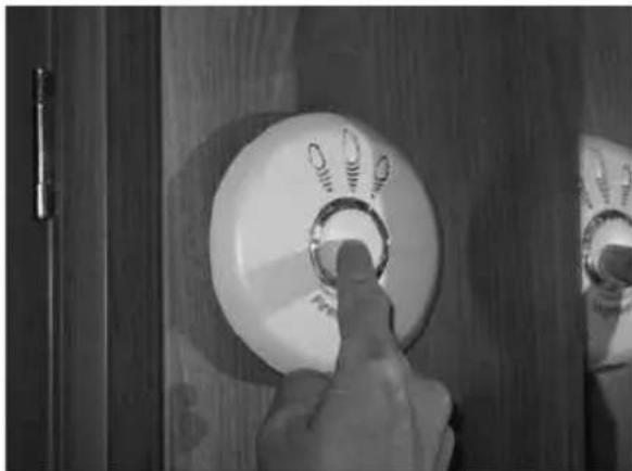
- Press the test button in the centre and release.
natural_image
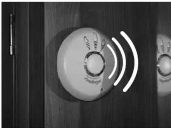
Close-up of a hand pressing a circular button on a wooden door (no visible text or symbols)- The unit will emit a loud (85dB at 3 meters) alarm for around 5 seconds and stop automatically.
natural_image
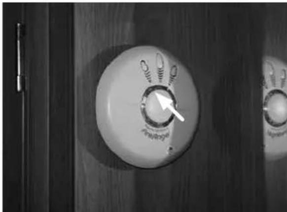
Close-up of a wall-mounted device with a circular dial indicator and white signal waves (no text or symbols visible)- The red LED on your alarm will flash rapidly during the audible signal.
natural_image
Close-up of a circular industrial control knob with a white arrow pointing to the center (no visible text or symbols)FIRE ALARM
Note: The test button accurately tests the alarm's smoke sensing circuit, there is no need to test your alarm with smoke. If your smoke alarm fails to give an audible test signal, please refer immediately to the troubleshooting guide at the end of the alarm user manual.
⚠ WARNING: Test your smoke alarm at least once per week
Your smoke alarm has been designed to be as maintenance - free as possible and although the unit requires only battery maintenance for its entire life, there are several things you must do to keep it working properly.
⚠ WARNING: Your smoke alarm is a sealed electrical device and no attempt should be made to open the case. Attempting to open the case will invalidate your Warranty.
Testing: Test your smoke alarm once every week, see page 39 on how to do this.
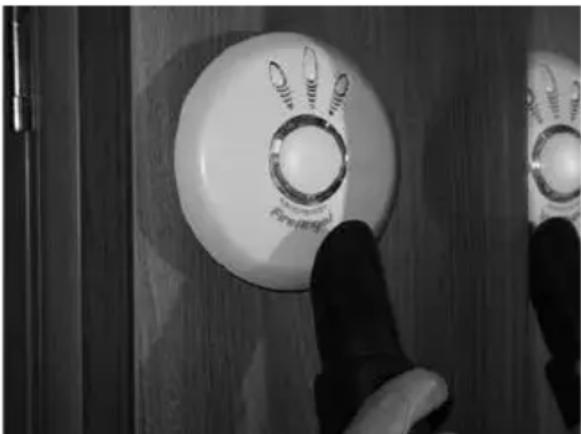
Cleaning: As a minimum your smoke alarm should be cleaned once every 3 months using your vacuum cleaner fitted with the soft brush attachment.
natural_image
Close-up of a hand pointing at a white circular control panel with 'Penset' label, mounted on wooden door (no readable text beyond label)⚠ WARNING: Your smoke alarm may false alarm when it is being cleaned using a vacuum cleaner.
⚠ WARNING: Do not use solvents or cleaners on your smoke alarm, as they may cause damage to the sensor or circuitry. The unit can be wiped with a slightly damp cloth
⚠ WARNING: The electronic test button provides a full test of the unit's functionality. DO NOT try to test the alarm with a naked flame, as this may present a potential fire hazard.
⚠ WARNING: Never use portable cooking or heating equipment other than electric heaters that are not of the direct radiant type, as it is a fire and asphyxiation hazard.
⚠ WARNING: Appliances such as cookers must not be used for heating.
Fire Extinguisher
It is recommended that a dry powder fire extinguisher be carried inside your caravan at all times.
When using a dry powder extinguisher it is suggested that the caravan be evacuated until the powder has settled, to avoid inhalation.
A fat pan fire should not have a fire extinguisher aimed at it. It should be smothered with a fire blanket.
⚠ WARNING: Provide one dry powder fire extinguisher of an approved type or complying with ISO 7165, of at least 1kg capacity, by the main exterior door and a fire blanket next to the cooker. Familiarise yourself with the instructions on your fire extinguisher and the local fire precaution arrangements.
Escape paths
It is important that you do not block escape paths to emergency exits with obstructions or hazards.
Children
Do not leave children alone in the caravan in any event. Keep potentially dangerous items out of reach, as at home e.g. matches, medicine etc.
CO alarm
Fireangel CO-9D Carbon Monoxide Alarm
⚠ WARNING: Please read the full user instructions provided.
Carbon monoxide
Known as the silent killer, Carbon Monoxide is an invisible, odourless and tasteless gas.
What are the symptoms of carbon monoxide poisoning?
Early symptoms of carbon monoxide (CO) poisoning can mimic many common ailments and may easily be confused with flu or simple tiredness. Symptoms to look out for include:
- tiredness
- drowsiness
- headaches
- giddiness
- nausea
• vomiting - pains in the chest
- breathlessness
- stomach pains
- erratic behaviour
- visual problems
Anyone with these symptoms should immediately turn off all appliances and seek medical attention.
What to do during an alarm
- Keep calm and open the doors and windows to ventilate the caravan.
- Stop using all fuel burning appliances and ensure, if possible, that they are turned off.
- Evacuate the caravan leaving the doors and windows open.
- Do not re-enter the caravan until the alarm has stopped. When exposed to fresh air it can take up to 10 minutes for the sensor to clear and the alarm to stop depending on the level of carbon monoxide detected.
- Get medical help immediately for anyone suffering the effects of carbon monoxide poisoning (headache, nausea), and advise that carbon monoxide poisoning is suspected.
- Do not use the appliance again until it has been checked by an expert. In the case of gas appliances the engineer must be Gas Safe registered.
CO ALARM
Power Pack Activation
See diagram below
Your detector comes complete with an integrated power pack that will provide power for its entire operational life. To activate the power pack you need to pull the disabling tab (see image). This will in turn pull out the metal disabling clip, which is attached to the end of the tab, from the disabling socket which is situated on the underside of the detector. Retain the disabling tab for future use by taping it to page 22 of the CO-9D user manual.
When the detector is activated the screen will display all of the icons, then after a few seconds will show the current CO level. The power indicator LED below the symbol will also flash green once every minute to indicate that the detector is receiving power from the power pack and is fully operational. A symbol will also flash briefly on the LCD screen approximately once every minute.
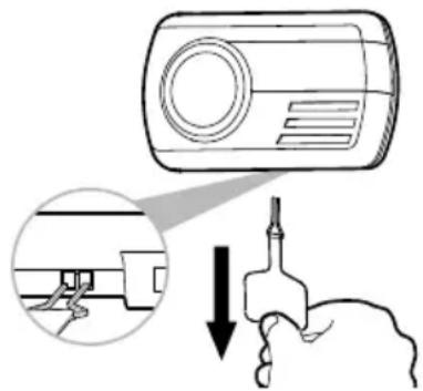
Test the sounder, power pack and circuitry by pushing the centre of the Test/Mode button briefly to confirm that the detector is operating properly. The sounder will sound as soon as the button is pressed, and the Alarm LED will illuminate red indicating that the sounder is working and the power pack is providing power to the unit. You'll notice that the display will switch to temperature mode, this is explained later in the manual, press button again to return to the CO display. This test for the sounder, power pack and circuitry should be performed on a weekly basis. This should be continued for the lifetime of the product.
⚠ WARNING: Prolonged exposure to the sounder in close proximity to your ears may damage your hearing.
Under normal operating conditions, the power pack will last for the lifetime of the product i.e 7 years. The detector will not protect against the risk of carbon monoxide poisoning when the power pack has drained.
⚠ WARNING: Prolonged exposure to extreme high or low temperatures may reduce the life of the power pack.
Power Pack Deactivation
Your CO-9D is portable making it ideal for taking with you on holiday. You will need to deactivate your detector when traveling or even when storing e.g when decorating. Fitting is reverse of removal. To deactivate the detector the two ends of the metal clip must be inserted into the corresponding holes in the disabling socket located on the underside of the detector (see image). You can ensure that the product is disabled by pressing the test button- If there is no sound from the sounder then the clip has been fitted correctly.
The clip must remain in the disabling socket to keep the power pack deactivated.
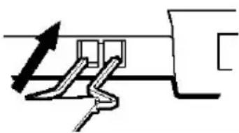
natural_image
Pure mechanical diagram showing a zigzag component with an arrow indicating direction (no text or symbols)Note: If the disabling tab is no longer available then the clip can be replicated by opening out a thin metal paper clip into a U-shape.
Operating Features
Standby Mode
The alarm can display two views when in normal standby mode, the current level of CO or the current room temperature in degrees centigrade (°C). When the alarm is showing the
current CO Level you will see something similar to the following.
FireAngel's unique digital read out displays the amount of CO that the sensor is detecting shown in parts per million (PPM). It is designed to indicate levels from 10PPM to 999PPM.
Note: Ambient background levels between 0PPM and 10PPM will show as 0PPM
When the alarm is showing the current temperature you will see something similar to the following.

In both modes you will notice a symbol appear briefly in the top left hand corner of the screen once every minute. This is an additional indication to show you that the alarm is operating as well as the flashing green LED.
To switch between CO and temperature view, simply press the Test/Mode button briefly. The unit will also sound when pressing the button to switch between the two display modes.
You will also notice that when switching between modes the display will change slightly, this is because the alarm is displaying the Peak Level CO reading that it has recorded in the last 4 weeks, please see the following peak level reading feature section for further description.
Note: If the alarm is in temperature view and detects CO it will automatically switch back to CO display mode.
Power pack, sounder and circuitary test
Pressing the Test/Mode button will also test the power pack, sounder and circuitry of the alarm. The unit will sound and the alarm LED below 🚙️ will illuminate red. You should perform this test once per week.
Peak Level Reading feature.
The alarm will record the highest reading of CO that it has detected in the last 4 weeks. This information is useful if your alarm has sounded so you can see the highest level of CO detected during that time. It is also useful to check periodically to see if a readable level of CO has been detected for a short time, but not long enough to trigger a full alarm. The peak level reading is shown briefly every time you press the Test/Mode button and will look something like the image below.
Note: It is possible and quite normal for the peak level to remain at 0ppm, i.e. this simply means that the alarm has not detected any CO in the last 4 weeks.
The Peak Level reading will be reset to 0ppm whenever a Sensor Test is carried out. (See the next section for Sensor Test).
Sensor Testing
⚠️ CAUTION: Sensor testing should only be performed by a responsible adult. This test should only be performed once a month. Excessive testing will shorten the life of the power pack.
CO ALARM
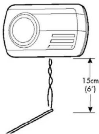
Note: We suggest the use of an incense stick or cigarette as the way in which these products burn produces a readable localized amount of CO. A readable level of carbon monoxide will not be given off by other sources of smoke, for example an extinguished candle or match.
Step 1: If the alarm is wall mounted unhook it from the fixing screws.
Step 2: Hold the Test/Mode button down until the spanner icon appears in the bottom left hand corner of the screen and the bar graph 'scans' from left to right. This indicates the alarm is in sensor test mode where the sampling rate of the sensor has increased and the alarm can be tested using a known source of CO.
Step 3: Light an incense stick or cigarette using a match or lighter. Extinguish the lighter, or put out the match and place it into a dish of water.
Step 4: Hold the incense stick or burning cigarette 15cm (6 inches) below the detector, so that the smoke goes into the holes at the bottom of the detector. As the smoke gets into the alarm the display will show the amount of CO being detected. When the level of CO in the sensor reaches 50ppm the alarm will sound a single alarm cycle, this confirms that the sensor is working correctly and is the end of the sensor test. The alarm will return to normal standby mode.
Step 5: Put out the incense stick or cigarette by placing it into a dish of water. Ensure that all flames have been extinguished.
Note: If the level of CO in the sensor doesn't reach 50ppm then the Sensor Test mode will time out and finish automatically after 3 minutes. Even if the level doesn't reach 50ppm, as long as the display shows a reading of CO then you can be confident that the alarm is working correctly. If you have any questions about testing the sensor please contact the technical support team
Understanding the Product's Indicators
Digital Display
The LCD screen has many icons with one or more being shown at any one time.
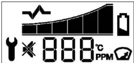
Bar Graph to show early build up of CO.
To understand the role of the product indicators please refer to section ‘Carbon Monoxide and how it can affect your family’ on page 3 of the CO-9D User Manual. The alarm has a bar graph which mimics the way CO levels build up in the blood stream. The response times of the alarm are determined by the European Standard BS EN 50291:2001 so the alarm will only sound when it has detected CO for a prescribed length of time, the higher the level of CO the quicker the alarm must sound. However with FireAngel’s CO-9D there is an early visual warning that CO is present. When CO is first detected the alarm indicates it’s presence by displaying the level on the screen in parts per million (ppm). If CO continues to be present additional bars will appear on the graph. When the graph is full
(i.e. the 6th segment is shown the unit will sound a loud audible alarm (85 dB at 1m (3 feet)) and the Alarm LED below the symbol on the front of the detector will flash red once every second.
natural_image
Abstract black-and-white graphic of a rising trend line with no text or symbolsThe Alarm will sound
- Between 60 and 90 minutes when exposed to a minimum of 50ppm of CO.
- Between 10 and 40 minutes when exposed to a minimum of 100ppm of CO.
- Within 3 minutes when exposed to a minimum of 300ppm of CO.
Alarm silence

It is possible to temporarily silence the alarm up to two times if the level of CO that triggered the alarm is less than 200ppm. After ventilating the property you can temporarily silence the alarm by pressing the Test/Mode button, the alarm will stop and the silence mode symbol will appear on the screen. The silence mode will last for up to 3 minutes. If the CO level remains too high the alarm will trigger again or if the level of CO rises above 200ppm then the detector will automatically re-enter alarm mode. If the level of CO has fallen to a satisfactory level the silence mode icon will disappear, the unit will exit alarm mode and the segments of the bar graph will slowly disappear as the CO in the sensor clears.
Alarm in absence:

If the Peak level reading symbol is showing on the screen but there is no full alarm sound and you are not pressing the test button, then your detector is warning that it has detected Carbon Monoxide in your absence. Immediately vacate the premises and seek medical attention for anyone suffering the effects of CO poisoning (headache, nausea). Treat this as a serious warning. Call a qualified technician and have the problem investigated and rectified immediately.
Error signal
Err The unit continuously checks the settings of its sensor and circuitry. If any of these settings are found to be incorrect, the detector will emit a single chirp once per minute and the display will show "Err" for error and an error code, cycling between "Err" and the particular error code.

Low power pack signal
If the power pack becomes low then the detector will emit a single chirp once per minute and the low power pack icon will flash on the screen.
⚠️ IMPORTANT: A single chirp once per minute together with an error signal 14 or low power pack warning does NOT mean that the detector has detected carbon monoxide.
If you experience an error condition or low power pack warning and the product is still within warranty then contact technical support. If the product is no longer in warranty replace immediately!
CO ALARM
⚠️ IMPORTANT: The selected power pack was chosen to provide power beyond the lifetime of the product, in particular the sensor (under normal operating conditions). The operational life of the sensor is seven years, for this reason, the detector should be replaced after seven years from the date of installation.
FireAngel Technical Support Line
9.00am – 5.00pm, Monday – Friday
Telephone: 0800 141 2561
(1-800 523171 in EIRE)
e-mail: technicalsupport@fireangel.co.uk
Maintenance
Your detector will alert you to potentially hazardous CO concentrations in your caravan when maintained properly. To maintain your FireAngel detector in proper working order, and to ensure that the sensor will last for the lifetime of the product, it is recommended that you:
- Test the sounder, power pack and circuitry of your detector at least once per week by pressing the Test/Reset button briefly (see above).
- Perform the Sensor Test once every month (See p42).
- Keep the detector free of dust by gently vacuuming the case with a soft brush attachment once per month.
To prevent the possibility of contaminating the sensor in your detector and thus affecting its reliability:
- Never use cleaning solutions on your detector. Simply wipe with a slightly damp cloth.
- Do not paint the detector.
- Do not spray aerosols on or near the detector.
- Do not use any solvent based products near the detector.
- Move the detector to a safe location and store in a plastic bag before painting, wall
papering, or performing any other activities using substances that emit strong fumes. Remember to remove it from the bag and replace the detector when these activities are finished.
Failure of any test should be reported to the Fireangel Technical Support Team. Do not attempt to repair your CO detector. Do not remove any screws or open the main casing of your detector. Any attempt to do so may cause malfunction and will invalidate the warranty.
What to do in the event of an alarm
⚠ WARNING: A loud alarm is a warning that unusually high and potentially lethal levels of carbon monoxide are present. Never ignore this alarm, further exposure can be fatal. Immediately check residents for symptoms of carbon monoxide poisoning, and contact the proper authorities to resolve all CO problems.
NEVER IGNORE ANY ALARM.
Please carefully review this owner's manual to ensure that you know what actions to take in the event of an alarm.
What to do during an alarm
Within 3 minutes when exposed to a minimum of 300ppm of CO.
- Keep calm and open the doors and windows to ventilate the property.
- Stop using all fuel burning appliances and ensure, if possible, that they are turned off
- Evacuate the caravan leaving the doors and windows open.
- Do not re-enter the caravan until the alarm has stopped. When exposed to fresh air it can take up to 10 minutes for the sensor to clear and the alarm to stop depending on the level of carbon monoxide detected.
- Get medical help immediately for anyone suffering the effects of carbon monoxide poisoning (headache, nausea), and
advise that carbon monoxide poisoning is suspected.
- Do not use the appliance again until it has been checked by an expert. In the case of gas appliances the engineer must be registered.
Note: If the level of CO in the sensor doesn't reach 50ppm then the Sensor Test mode will time out and finish automatically after 3 minutes. Even if the level doesn't reach 50ppm, as long as the display shows a reading of CO then you can be confident that the alarm is working correctly. If you have any questions about testing the sensor please contact the technical support team
Disposal
Waste electrical products should not be disposed of with regular household waste. Please recycle where facilities exist. Check with your local authority, retailer or manufacturer for recycling/disposal advice as regional variations apply. The power pack should be deactivated before disposal. To do this, insert the two ends of the metal clip on the end of the disabling tab back in to the socket located on the underside of the detector. If the disabling tab is no longer available then the clip can be replicated by opening out a thin metal paperclip into a U-shape. You can also return your carbon monoxide detector to Fireangel for disposal. For return address contact Fireangel Technical Support. Please include a note confirming the product is being returned for disposal.
Technical Information
Detector Specifications: Model CO-9D Sensor Type: Electrochemical Sensor Life: 7 Years Alarm Sound Level: 85dB at 1 metre (3 feet) Power Pack Life: 7 years (Life of product) Temperature Range: -10°C (14°F) to 40°C (104°F) Operating Humidity Range: 30 - 90% RH Weight: 120 grams (4.23oz) Certified to: BS EN 50291:2001
This FireAngel carbon monoxide detector is designed to continuously monitor for CO. Its response times meet the requirements of BSI standard BS EN 50291:2001.
⚠ WARNING: DO NOT ATTEMPT TO OPEN - DO NOT BURN

⚠ WARNING: APPARATUS CONFORMING TO THIS STANDARD MAY NOT PROTECT PEOPLE WHO ARE AT SPECIAL RISK FROM CARBON MONOXIDE EXPOSURE BY REASON OF AGE, PREGNANCY OR MEDICAL CONDITION. IF IN DOUBT, CONSULT YOUR DOCTOR.
A CARBON MONOXIDE DETECTOR IS NOT A SUBSTITUTE FOR A SMOKE ALARM OR A COMBUSTIBLE GAS DETECTOR.
REPLACE UNIT AFTER 7 YEARS OF OPERATION.
VENTILATION/SECURITY
7 Year Warranty
FireAngel Ltd warrants to the original purchaser that its enclosed carbon monoxide alarm be free from defects in materials and workmanship under normal residential use and service for a period of 7 (seven) years from the date of purchase. Provided it is returned with postage paid and proof of purchase date, FireAngel Ltd hereby warrants that during the 7 (seven) year period commencing from the date of purchase FireAngel Ltd, at its discretion, agrees to replace the unit free of charge. The warranty on any replacement CO-9D alarm, will last for the remainder of the period of the original warranty in respect of the alarm originally purchased – that is from the date of original purchase and not from the date of receipt of the replacement product. FireAngel Ltd reserves the right to offer an alternative product similar to that being replaced if the original model is no longer available or in stock. This warranty applies to the original retail purchaser from the date of original retail purchase and is not transferable. Proof of purchase is required.
This warranty does not cover damage resulting from accident, misuse, disassembly, abuse or lack of reasonable care of the product, or applications not in accordance with the user manual. It does not cover events and conditions outside of FireAngel Ltd's control, such as Acts of God (fire, severe weather etc.). It does not apply to retail stores, service centres or any distributors or agents. FireAngel Ltd will not recognise any changes to this warranty by third parties.
FireAngel Ltd shall not be liable for any incidental or consequential damages caused by the breach of any expressed or implied warranty. Except to the extent prohibited by applicable law, any implied warranty of merchantability or fitness for a particular purpose is limited in duration for 7 (seven) years.
This warranty does not affect your statutory rights. Except for death or personal injury, FireAngel Ltd shall not be liable for any loss of use, damage, cost or expense relating to this product or for any indirect, or consequential loss, damages or costs incurred by you or any other user of this product.
Ventilation
All caravans comply with BS EN 721. The ventilation points on your caravan are fixed points of ventilation which are required by the European Standards.
All caravans have ventilation at high level and low level which have been calculated to suit the individual needs of your caravan.
High level ventilation is achieved by means of the roof lights and washroom roof ventilators. The low level ventilators are positioned underneath the oven housing.
Under no circumstances must these vents be blocked or obstructed.
It is advised that fixed ventilation points are checked and cleaned (if necessary) on a regular basis using a small brush and a domestic vacuum cleaner.
Additional night time ventilation is obtained by releasing the window catches and placing them in the second groove. Note the windows are not sealed from rain in this position. As the ventilation levels are calculated to suit each models requirements there should be no modifications made which may result in reduced ventilation levels.
⚠ WARNING: Do not obstruct ventilation
Petrol/Diesel Fumes
The fitting of a tail pipe extension to your car exhaust will reduce the possibility of fumes entering your caravan through the ventilation points.
Security
Caravan theft
The theft of a caravan can occur in the most unlikely circumstances; from a motorway service area, even from an owner's driveway.
Secure all windows and doors when your caravan is unoccupied even if only for a short length of time.
Security chips
A special security chip is concealed within the body of every caravan. This chip contains the individual identity of your caravan and can only be read by using a special decoder by police officers.
Chassis number
Your 17 digit serial number chassis number can be found on your windows and on the offside chassis member of the drawbar. It is also stated on the manufacturers weight plate next to the doorway.
Make a note of this number in the space provided at the front of this handbook and make a separate note of the number to keep safe at home.
Additional security
Consider fitting any device which might deter or prevent intrusion by thieves.
A hitch lock cover prevents towing of the caravan.
A wheel lock prevents towing of the caravan and removal of the wheel (some models are provided with an AL-KO Secure device).
Customers are advised to identify their caravan with a method for subsequent identification if other forms of identification have been altered or removed.
Free crime prevention advice about securing your caravan, protecting your valuables, property marking, either at home or whilst on site, can be obtained from the Crime Prevention Officer through your local Police Station.
Caravan insurance
It is recommended that the caravan and its contents should be insured against theft.
It is essential to check with your car insurance company to ensure you are covered when towing your caravan.
AL-KO secure immobiliser
The AL-KO immobiliser is fitted as standard on some models, optional on others. When fitted the 4 part kit specified below is supplied with your caravan. Your kit will contain: -
Part A
Box containing security components. consisting of:
- 1off High security locking bolt.
- 1off High security locking bar socket key.
- 1off Barrel lock.
- 2off Barrel lock keys.
- Instruction manuals in CD and paper format.
- Security registration card and reference number.
Part B
Wheel specific insert assembly consisting of:
- Red coloured wheel insert lozenge assembled with the locking bar and clip.
Part C
- 1off Wheel spanner.
Part D
- Kit bag.
TRACKER RETRIEVE UNIT
You must register your key within one month of the date of purchase. Should you fail to do this, you will not be able to order a spare key!
- Within your AL-KO kit you will find an exclusive security number.
- Please register your card by telephoning 0870 7576788 or 0044 1926 818500.
- You will need to provide a password and provide an answer to a prompting security question.
- Make a note of your password and keep it in a safe place.
- Keep your registration card safe.
- Take your registration card with you when you are travelling with the caravan.
- Always keep your registration separate from the lock.
Safety information (AL-KO secure)
- Always secure the caravan against rolling away (chock or couple to a towing vehicle).
- Always remove AL-KO Secure before moving the caravan.
- After any attempt of theft has been made on a locked AL-KO Secure, the caravan must be inspected at an AL-KO Approved Service Workshop.
- Always keep the key in a safe place.
- Keep the lock set and registration card separate from the key.
- The lock parts and key do not have a registration number, therefore keep the registration card in a safe place.
- Caravans with twin axles have two locks, keep each lock set in a separate place.
The sets are not interchangeable!
AL-KO operating instructions
- Read the AL-KO operating instructions and act in accordance with them.
- Follow all safety instructions as well as the warning information.
- It is recommended for ease of fit that a side-lift jack be used.
- Keep the operating instructions
The AL-KO side lift jack
(Supplied as standard on specific models only).
The AL-KO Side Lift Jack has been specifically developed to aid the often difficult process of changing a wheel on caravans. It is suitable for fitment to the AL-KO chassis, located in the pre-drilled holes in the longitudinal members.
Note: The fitment of some aftermarket motor movers may inhibit the use of the AL-KO jacking system.
Tracker battery powered retrieve unit
Your vehicle is fitted with a ‘TRACKER Battery Powered Retrieve’ unit. This is a self contained security device which has been positioned discreetly within the vehicle during the manufacturing process. There are numerous fitting positions for the device, the locations of which are kept secret and known only to TRACKER and the Swift Group.
This unit has a self contained battery, which has a minimum five year life. The unit draws no power from the vehicle battery or leisure battery. This unit is a tracking device only and is not an alarm.
The tracking device requires an active subscription to be in place with TRACKER. Your vehicle is supplied with a free 3 month subscription (from date of purchase), which is activated once you have registered your details with TRACKER (normally your dealer would do this with you at the time of collection of your new vehicle). If you chose not to register your device the unit is not activated and the
vehicle can therefore not be tracked in the event of theft. At the end of the free 3 month subscription period your subscription will end. Owners can however choose to either subscribe to TRACKER for a further 12 months at £60 per year or for a period of five years from date of purchase at £199. The TRACKER unit subscription cannot be subscribed to for longer than five years from the date of purchase and a new TRACKER unit would need to be installed and registered separately after the five year period has elapsed.
If in the unfortunate event your vehicle is stolen you should;
- Notify the police immediately.
- Contact TRACKER and confirm to them that your vehicle has been stolen and provide a police crime number.
- TRACKER will then activate the tracking device in your vehicle.
- The police can then track the vehicle using VHF tracking technology from the tracking computers inside police vehicles and aircraft.
- Once located TRACKER will inform you.
The device works in some (but not all) European countries (further details of which can be obtained from TRACKER). http://www.TRACKER.co.uk/
TRACKER's telephone number is: 0845 602 2356
Mobile alarm system
Stinger 310 alarm (if fitted)
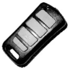
natural_image
Black rectangular electronic device with four slots, no visible text or symbolsIntroducing the new Sargent STINGER 310 series modular alarm system.
Based on new technology and a two year design process, the Stinger 310 incorporates ideas and feedback from users and experts throughout the caravan and security industries.
Designed to be modular, the system can be expanded by a forthcoming range of wired and wireless accessories.
To ensure your STINGER 310 system is operated correctly, please read all sections of these instructions before attempting to use the alarm. If you are unsure of any content, please contact your dealer in the first instance or Sargents Electrical direct.
Operation - using the key fob
Each STINGER 310 is supplied with two key fob style radio controllers, which are used to operate the alarm system. Each key fob has four buttons which can be used as follows;

LED Torch button
Press and hold the button to use the torch for night time convenience

Arm / Disarm button
Press and release the button to arm the alarm (one beep)
Press and release the button to disarm the alarm (two short beeps)
To arm the alarm without the PIR movement sensor (if you leave pets inside etc)
Press and hold the arm button and release after you hear one beep followed by two beeps
ALARM SYSTEM

Awning Light button
Press and release the button turn the awning light on or off (note: awning light control is an optional feature not present in all caravan models)
Operation - the PIR internal movement sensor
The STINGER 310 comes complete with a 120° Passive Infra Red (PIR) internal movement sensor that detects body movement within the vehicle.

Programming Mode button
Press and hold the button for 10 seconds to access the 3 programming modes, which are indicated by series of long beeps, as follows:
natural_image
Close-up of a square electrical outlet switch (no text or symbols visible)If you are leaving pets within the vehicle the system should be armed without the PIR sensor active (see key fob arm/disarm section) to prevent your pet from triggering the alarm.
One long beep
- Tilt sensor sensitivity adjustment
Press the arm/disarm button to select the required setting. 1 beep = low sensitivity for windy conditions. 2 beeps = standard sensitivity (default). 3 beeps = High sensitivity. Press the program mode button to move to the next setting.
Two long beeps - Beeper volume
Press the arm/disarm button to cycle through the 7 available volume levels. When you are happy with the selected volume, press the program mode button to move to the next setting.
Three long beeps
- PIR movement detector sensitivity
Press the arm/disarm button to select the required setting / pulse count. 1 beep = high sensitivity 2 beeps = standard sensitivity (default). 3 beeps = Low sensitivity for hostile environments.
Press the program mode button again to exit programming mode, which is indicated by one extra long beep.
Please be aware that direct sunlight onto the PIR lens, or extremes of temperature (above 30 deg C) may affect the operation of the detector. Always ensure roof light blinds are closed if sunlight could shine directly onto the PIR.
Operation - the tilt sensor
The STINGER 310 incorporates a new electronic tilt and motion sensor with automatic calibration and easy sensitivity adjustment from the key fob. This feature provides excellent tilt detection with no moving parts.
The tilt sensor works automatically and does not need adjustment for normal use even if you park on a steep incline. The sensitivity of the sensor can be adjusted as described in the key fob programming section.
Operation - awning light (model specific)
When the STINGER 310 alarm system is armed or disarmed the Awning light will be activated for a period of one minute to provide illumination whilst entering or exiting the caravan. The Awning light can be turned off during this period by pressing the Awning light button on the key fob if required. (Note: awning light control is an optional feature not present on all caravan models)
The Awning light can be turned on or off at any time by pressing and releasing the Awning light button.
Battery - system base unit
The STINGER 310 system unit uses a special 4.8 volt Nickel Metal Hydride battery pack that supplies backup battery power to the system should the supply from the leisure battery fail or be disconnected.
It is recommended that the alarm system is permanently connected to a 12 volt supply. When fully charged the battery will provide approximately 6 months stand-alone operation, depending on temperature conditions. It is recommended that this battery pack is replaced every 3 years.
Before placing your caravan in storage please ensure the caravan has had a fully charged leisure battery fitted or the mains charger switched on for at least 14 days prior to storage to ensure the internal backup battery is fully charged. It is recommended that a leisure battery remains connected to the caravan during storage.
Always dispose of old batteries in accordance with local regulations.
Battery - key fob
The STINGER 310 key fob controllers use two lithium button cells (CR 2032) in each key fob. Please note that excessive use of the LED torch will reduce the life of the batteries considerably.
To replace the batteries, firstly remove the four cross head screws from the underside of the fob, then pull apart the two halves of the fob. Remove the used batteries from the lower half of the case, then insert the new batteries in the same manner, noting that the battery positive faces away from the green circuit board. Now reassemble the fob casing and refit the screws, taking care not to over tighten.
Alarm siren
The STINGER 310 contains a dual sounder unit that provides the loud alarm siren and the volume adjustable beeper sound.
When the alarm is triggered the siren will sound for 2 minutes. Following the 2-minute period the alarm will then deactivate for 15 seconds and then rearm.
The alarm siren can be turned off at any point by pressing the key fob arm/disarm button.
When the alarm is disarmed the Beeper will sound two beeps to confirm the disarm. If the alarm has been triggered during the armed period the beeper will sound three beeps if the PIR triggered the alarm or four beeps if the Tilt Sensor caused the alarm. If you hear multiple pips (short beeps) when you disarm the alarm, this indicated that the internal backup battery is low and therefore should be charged.
The beeper volume can be adjusted using the key fob programming feature described earlier.
System specification
System base unit:
• Supply voltage 6 to 15v DC
• Supply current 500mA max 5mA typical
- Operating temperature -5 to +30 deg Celsius
- Battery capacity 9Ah at 4.8v
- Siren output 110dB +/- 10% @ 1M
- Comprehensive interface connector (details on request)
PIR movement sensor:
- Range 120 deg x 6M
Key fob controller:
- Range 6M typical
- Battery 2x CR2032 lithium button cell
• Typical battery life 1 year
ALARM SYSTEM
Spare parts & service
The STINGER 310 system is supplied with two key fob controllers as standard, but can accommodate up to four controllers per system. Extra fob can be purchased from your supplier of direct from the manufacturer, and can be added to the system by following a simple procedure.
For accessories, interface harnesses, installation documentation, spare parts, local supplier contact details or other service information please contact: Sargent Electrical Services Ltd. service desk on 01482 678981 during normal office hours.
Further technical information is available at www.sargentltd.co.uk
For future reference it may be useful to note your alarm system serial number below, which can be found on the sticker attached to the alarm system base unit.
Serial number:
SERVICES
Water System.... 56
Tank types 57
Plumbing connections 60
Plumbing troubleshooting....61
Fresh level sensor & cleaning....62
Pressure switch adjustment.... 62
Ultraflow Water Intake Housing.... 63
Sanitising water system 64
Water Fault Finding.... 65
Typical gas schematic drawing 67
Gas 68
Types of gas 70
Gas safety advice 70
Ventilation 71
Gas Fault Finding 72
Electrical system 73
Overseas connection 73
13 Pin tow vehicle connections 74
230V mains electrical equipment power consumption 75
Wiring of connecting cable and caravan mains inlet 76
Typical appliance consumption figures 77
WATER SYSTEM
Water system- Introduction
All Swift Group caravans water systems have been designed around a pump fitted within the caravan. This pump draws water from an external source, to provide water pressure within the caravan, whenever it is switched on and water is available.
The schematic below shows the basic configuration of the water system with inboard pump and no internal water tank:
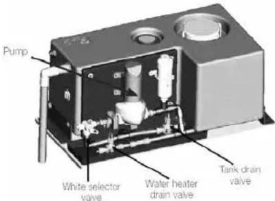
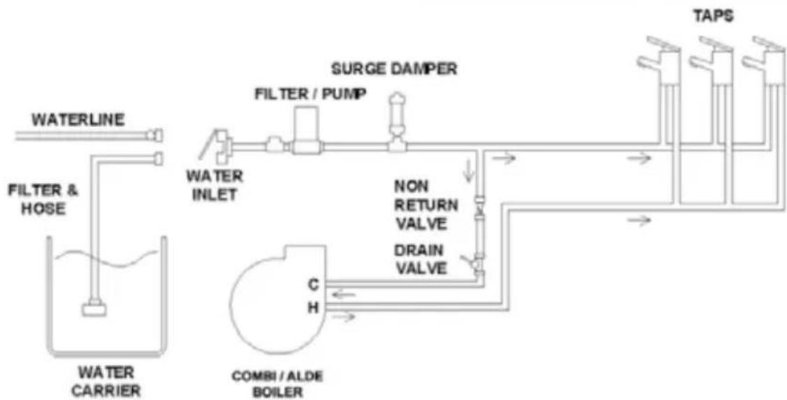
flowchart
graph TD
    A["WATER LINE"] --> B["FILTER & HOSE"]
    B --> C["MOBILI / ALDE BOILER"]
    C --> D["SURGE DAMPER"]
    D --> E["FILTER / PUMP"]
    E --> F["MON RETURN VALVE"]
    F --> G["DRAIN VALVE"]
    G --> H["TAPS"]
    H --> I["Output"]
    style A fill:#f9f,stroke:#333
    style B fill:#ccf,stroke:#333
    style C fill:#cfc,stroke:#333
    style D fill:#fcc,stroke:#333
    style E fill:#cff,stroke:#333
    style F fill:#ffc,stroke:#333
    style G fill:#cfc,stroke:#333
    style H fill:#fcc,stroke:#333
    style I fill:#ffc,stroke:#333
When power is supplied to the pump, it will draw water from the external container through the water inlet mounted on the side of the caravan, and pump it to the caravan taps, shower and water heater.
The pump is fitted with its own pressure switch, and the pump will continue to pump water, until the pressure of water on the output of the pump reaches a pre-set level. For this pressure to be achieved, the taps must be closed.
When the taps are opened, water will leave the tap via the spout, and the pressure in the pipes between the pump and the taps will reduce. Because of this reduction in pressure, the pressure switch on the pump will switch back on and the pump will again run to pump more water.
Close to the pump, the water under pressure is split into two paths:
-
Through blue water pipes routed directly to the cold connection of each tap.
-
To the water heater.
Water from the pump enters the bottom of the water heater. Once the water fills the water heater (typically 10 litres), water then leaves the water heater via a connection at the top of that water heater. This water, which is still under pressure, then routes to the hot connection of each tap via red pipes.
Tank types – Overview
No Internal Water Tank
A caravan water system with no internal water tank functions in the following way:
The inboard pump draws water into the caravan, via the inlet on the offside of the caravan. This is directed to the water heater, taps and shower. An umbilical hose, with baffle, is supplied with the caravan to connect between the inlet and an aquaroll or similar external container.
On Arrival at the campsite / Priming the system
- Ensure that the external water container is full.
- Close all of the taps (kitchen sink, bathroom, shower) except one, which should be open in the hot position.
- Ensure that the water heater drain valve is closed (move the Yellow handle on the floor near the water heater to a horizontal position).
- Switch the pump on using the button on the control panel. Water will flow through the open tap after a short time. This tap can then be moved to the cold position and again after a short time water will flow.
- Repeat the procedure at each tap, including the external shower point (model specific)
- When using a mains water connection the pump will still need to be switched on to supply water to the water heater, taps and shower.
- If a mains water connection is used, please ensure this is a Truma Waterline connection, which has a built in pressure reducing valve.
- To drain / winterise the system please see separate details later in this handbook.
WATER TANKS
Internal Water tank (UK Caravans)
The following arrangement is used for a caravan with internal water tank:
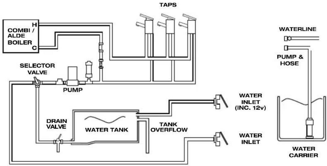
flowchart
graph TD
    A["COMBI / ALDE BOILER"] --> B["C"]
    B --> C["PUMP"]
    C --> D["DRAIN VALVE"]
    D --> E["WATER TANK"]
    E --> F["TANK OVERFLOW"]
    F --> G["WATER INLET (INC. 12v)"]
    G --> H["WATER LINE"]
    H --> I["PUMP & HOSE"]
    I --> J["WATER CARRIER"]
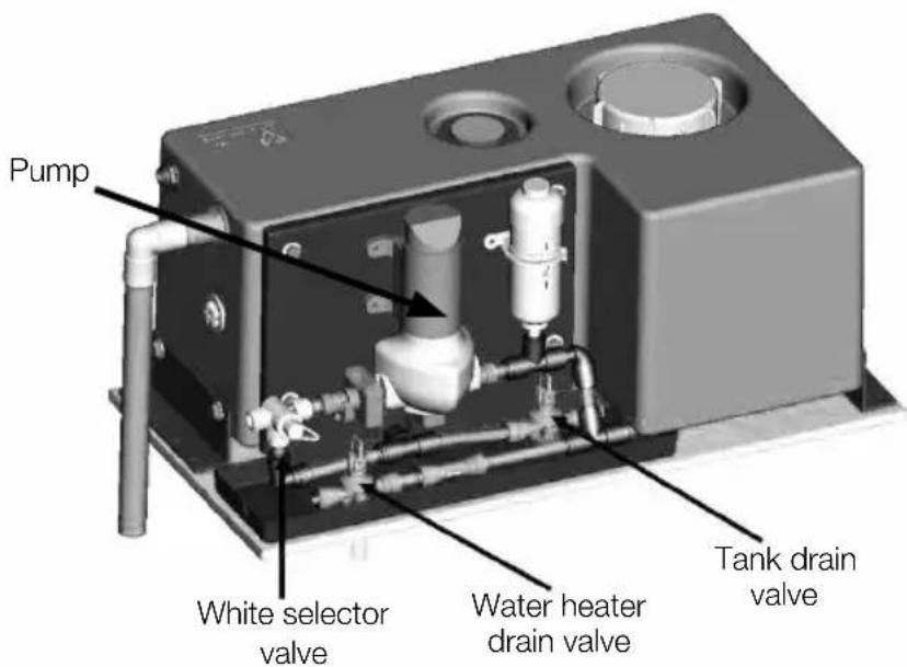
- Two water inlets are fitted on the outside of the caravan, on the offside. The upper inlet is used to fill the internal water tank, and the lower inlet is used to bypass the tank
- The inboard pump draws water from whichever water source is in use.
• A White selector valve located close to the
pump is used to select the water supply from the external source or the internal tank (see valve positions on the next page).
- An external pump is supplied with the caravan, this can be used with the lower inlet when the onboard pump is being used to draw water from an external source.
- The same external pump can be used with the upper inlet, this will transfer water from the external source to the internal tank.
- When filling the internal tank, monitor the amount of water in the tank and stop filling before the tank overflows via the switch on the control panel.
- Please see label on bed flap rear for valve operation.
- The control panel above the door has buttons to turn on and off both the internal and external pumps.
INTERNAL TANK SUPPLY
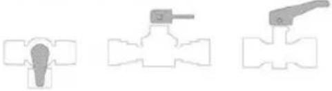
natural_image
Three technical line drawings of a valve component, showing different shapes and mounting points (no text or symbols)EXTERNAL SUPPLY
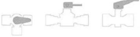
natural_image
Three schematic diagrams of a valve mechanism, showing different configurations (no text or labels)DRAIN SYSTEM
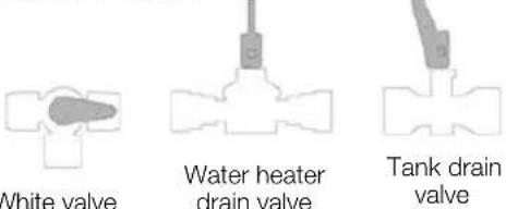
When using EXTERNAL SUPPLY ensure external pump is connected to lower outer socket. Upper socket is used only to fill internal tank
WINTERISATION / STORAGE
1) With external pump connected to upper external socket, lift the external pump out of the water container and allow the pump to run briefly.
2) Disconnect the external pump and set the valves to drain the internal tank and water heater, as shown opposite.
3) Open the kitchen tap, vanity tap, shower mixer and shower head to the fully open, mixed hot and cold position, and allow system to drain. Run the internal pump briefly.
4) Dis-connect input and output connections to the internal pump and allow water to drain from connections (including filter body). Remove filter until further use.
5) Again run the internal pump for short time to expel any water from the pump body.
6) Unscrew shower head, or shower head and hose, and shake dry.
7) It is advised to leave the pump, and shower head and hose, disconnected until further use.
Please also check handbook and/or appliance manufacturers instructions for further winterisation advice
On Arrival at the campsite / Priming the system
The caravan water system can be used with or without the internal water tank.
To use the caravan without the internal water tank:
- Ensure that the external water container is full.
-
Connect the external pump to the lower connection point on the outside of the caravan, labelled 'direct to taps'.
-
Move the White selector valve close to the pump anti-clockwise to select the external source.
- Close all of the taps except one, and follow the steps as detailed for a caravan without internal water tank.
To use the caravan with the internal water tank:
- Connect the external pump to the upper connection point on the outside of the caravan, labelled 'direct to tank'.
WATER TANKS
- Ensure that the tank drain valve (which is a Yellow handled valve identical in appearance to the water heater drain valve) is in the closed position - with the handle horizontal.
- Rotate the handle of the White selector valve clockwise to select internal tank as the water source.
- Press the 'tank fill' button on the control panel to transfer water from the external container to the internal tank.
- Water will now be transferred from the external container to the internal water tank. The amount of water within the internal tank can be checked by looking at the water level gauge on the control panel.
- Once the control panel shows this level at 14 or higher, taps can be used as normal.
- Press the 'water pump' button to switch on the internal pump.
- When the control panel display shows the internal tank as full, or the external container is empty.
- Press the 'Tank Fill' button to switch off the external pump. Refill the external container if required.
To use the caravan with a mains water connection:
- When using a mains water connection the pump will still need to be switched on to supply water to the water heater, taps and shower.
- If a mains water connection is used, please ensure this is a Truma Waterline connection, which has a built in pressure reducing valve.
- The Waterline connection should be connected to the lower connection point on the outside of the caravan, labelled as ‘direct to taps’.
Plumbing Connections
In most cases, speed fittings are used, which allow easy and quick connection of water pipes.
To connect a pipe to a fitting, simply push the pipe into the connector. To remove the pipe, push the collar of the fitting inwards, and then withdraw the pipe.
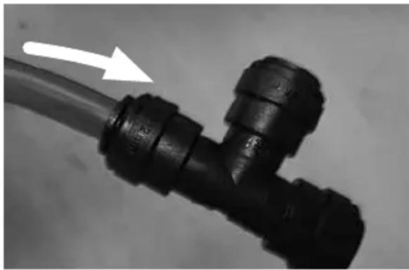
natural_image
Close-up of a black plastic pipe fitting with a white arrow pointing to it, no text or symbols visible.To connect a pipe, simply push the pipe into the connector.
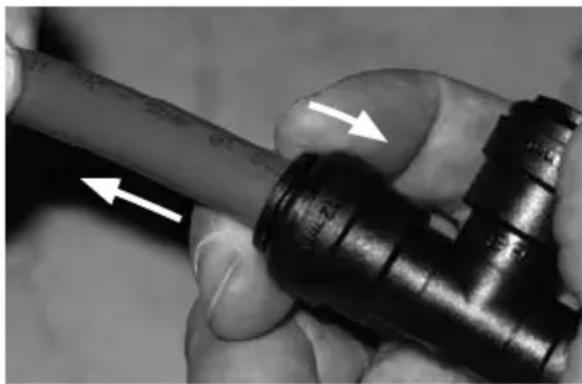
natural_image
Close-up of a hand holding a pipe fitting with directional arrows indicating movement (no text or symbols)To remove a pipe, push the collar inwards, and then remove the pipe.
As a note, when refitting the pipe, ensure the end of the pipe is round (not oval) and the cut is square. If not, it could lead to water leaks.
Troubleshooting
Pump will not start, when the tap is opened:
- Check fuse(s).
- Check power source(s), and ensure there is sufficient voltage to run the pump.
- Ensure 'pump' LED is illuminated.
- Using a multi-meter, ensure there is power at the pump. If not, refer to your dealer as there maybe damaged cabling or a fault with the fusebox.
- Is the pump hot? If so, allow to cool before retrying.
- Has the vehicle been stored over winter? Was it correctly winterised? If no, the pump may have frozen, causing permanent damage.
- The pressure switch may need adjusting. See page 62 on how to do this.
Pump runs, but will not pressurise system (i.e. no or little water being discharged from taps) - Not Pulsing:
- Ensure water in source is present (onboard tank or aqua roll).
- Check in-line pump filter is free from debris and correctly fitted.
- Ensure water system has been primed correctly, (see pages 57 and 59) and there are no air-locks present.
- Ensure there are no restrictions in the plumbing.
- Using a multi-meter, ensure there is power at the pump. If not, refer to your dealer as there maybe damaged cabling or a fault with the fusebox.
- Ensure the inlet side of the pump (including Truma inlet and in-line filter) are watertight and not allowing air into the system.
- Ensure the pump has good voltage.
- Check (using a multimeter) that the voltage at the pump is between 10v-14.5v.
Pump continues to run (for more than 5 seconds) after taps are closed or pump turns on for no reason:
- Check for leaks on the high pressure side of the pump.
- Ensure water system has been primed correctly, (see pages 57 and 59) and there are no air-locks present.
- Ensure the pump is securely mounted.
- Ensure the piping on the high pressure side of the pump is in good condition (not blowing or deforming).
- The pressure switch may need adjusting. See page 62 for information on how to do this.
Noisy or rough operation
- Check for leaks on the high pressure and low pressure side of the pump.
- Ensure that all pipes (especially those within 150mm of the pump) are not touching any furniture.
- Ensure the pump is securely mounted.
Pump rapidly cycles (switches on or off) or water pulses from taps, including temperature pulsing:
- Check for leaks on the high pressure and low pressure side of the pump.
- Ensure there are no restrictions in the plumbing
- The pressure switch may need adjusting. See Section (page 62) for information on how to do this.
WATER TANK SENSORS AND PRESSURE SWITCH
Fresh level sensor & cleaning
Principle
The sensor, fitted to Swift Group caravans are pre-fitted to water tanks, and link to the fusebox, via a pre-fitted wiring harness. The sensors, which consist of a number of stainless steel rods or probes, at different lengths, are immersed in the fresh water, and use the conductivity of water, between the probes, to provide a reading to the fusebox.
The sensors are 'digital', in that while the conductivity (resistance) value can vary, the fusebox will register any conductivity between the reference probe and the various different length probes, indicating water present.
Normally, even if the rods are dirty, and providing the rods have not bridged by a foreign object, a circuit will still be delivered back to the fusebox and a water level displayed.
Sensor cleaning
The first step, in case of fault diagnosis, is to clean the sensor rods. False water level reading at the control panel can be caused by calcium build up or foreign objects within the tank bridging the probes.
Sensor Cleaning Instructions
Cleaning recommendations for lime scale build up:
- Remove sensor from tank.
- Check probes for build up or contamination.
- Use clean soapy water.
- Place scourer in water and dampen.
- Apply scourer to sensor probe with limited pressure.
- Rub sensor probe removing contamination.
- Swill sensor with fresh clean water.
- Replace probe into tank.
Suggested scourers - food safe
Plastic mesh scourer
- Material: It is made of plastic.
- Usage: Used for cleaning steel utensils, dishes, pots, pans, ovens, Bar-B-Que grills, glass, cutlery, sinks, kitchen and bathroom tiles and tubs etc.
Water pump pressure switch
The purpose of a pressure switch is to monitor the pressure on the outlet side of the pump. When a tap is closed, and the pump continues to run, there is an increase of pressure in the system, and when that pressure reaches a pre-set limit, the pressure switch will turn the pump off.
Water pump pressure switch adjustment
Pressure Switch Adjustment, Truma/Flo-Jet pump. (Normally Grey upper section with White lower section/valve housing)
- All of the Truma/Flo-Jet pumps used by Swift are pre-set at 28psi + / -3psi.
- To further adjust the pressure switch setting, a cover cap must be first be removed from the end of the pump to reveal a pressure adjusting screw, as shown in the photos. A maximum of 1/4 turn clockwise or anti-clockwise, from the factory setting, is advised. Turning the screw clockwise 1/4 turn will increase the pressure switch cut-out pressure, turning the screw anti-clockwise will reduce the pressure setting.
- Please note a second screw mounted below the cover cap is set in position with threadlock, this should not be disturbed.
ULTRAFLOW WATER
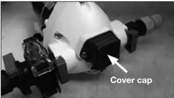
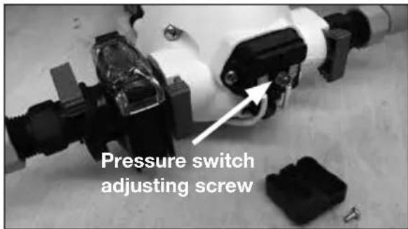
Ultraflow water intake housing
Operating instructions
Raise the lid, clean both the water socket and the plug of the Intake Assembly.
Plug the intake connector into the socket.
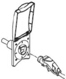
natural_image
Technical line drawing of a mechanical component with a tool inserted (no text or symbols)Place the assembly into the water container, ensuring that it is fully submerged before operating the system. The Dust cover is to stop contaminates falling into the water container.
When water is first introduced, or the water supply in the internal tank, or aquaroll, runs out, air will be present in the pipework. It is important that every tap is run to remove any air in the system before, for instance, the shower is used. Air left in pipework local to a tap can act as an accumulator and affect the ratio of hot and cold water flowing from other taps or shower mixers in the system.
If the pump fails to deliver water the most likely cause will be air in the system. Switch off the pump and shake the pump assembly in the external water container. Then switch on again.
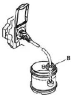
To remove the Intake Assembly from the Water Intake Housing. To remove, pull the lower trigger and pull out the hose plug.
⚠ WARNING: Do not remove by pulling the hose. Please ensure that the lid is properly closed before driving!
Routine maintenance
Ensure that the O-ring seal on the hose plug and the socket are free from dirt. To aid fitting of the plug assembly smear the O-ring with vegetable oil.
Notes
Before winter storage the water system must be completely drained (see winterisation / storage in the maintenance section).
Clean the water system at the start and end of the season with sterilising fluid (see notes under sanitising on the following page).
System care
Allowing water to freeze in the system may result in damage to the pump and plumbing system.
Non-Toxic antifreeze for potable water may be used with Truma pumps. Follow manufacturers recommendations.
⚠ WARNING: Do not use automotive antifreeze to winterize potable water systems. These solutions are highly toxic and may cause serious injury or death if ingested.
SANITISING
Sanitising
Guidance on cleaning portable water tanks and the water system in touring caravans.
The water systems, and in particular water tanks, in caravans are susceptible to contamination by bacteria if care is not taken with their use and cleaning. The symptoms caused by bacterial contamination are not purely limited to gastro-intestinal diseases, but may also manifest themselves as ear, nose, throat, eye or skin infections. It is therefore important that you carry out the following procedure prior to using the caravan each time, even if you boil or filter all water you use for drinking.
Separate Water Containers
- All water remaining in the container should be disposed of so that the container is empty.
- The outside of the container should be thoroughly cleansed and washed down to remove any dirt, dust or other contaminant. Water at a suitably hot temperature containing an appropriate detergent is recommended for this purpose.
- Water should be put in the container, swirled around, then emptied out.
- The container should then be totally filled with water containing an appropriate sterilant solution and allowed to stand for the recommended contact time.
- The solution should be emptied from the container.
- The opening of the container should be cleaned thoroughly with an appropriate prepared wipe impregnated with a sterilant.
- The container should be inverted whilst stored overnight (if possible).
- The container must be filled with mains water only and mains water only should be used for the above cleaning procedure.
- On no account should garden hoses be used to fill water tanks.
For Systems:
- Drain down the system (open all taps to allow air in, enabling the system to drain quickly).
- Remove any after market water filters fitted, and replace with a short length of hose or empty filter cartridge (this will ensure the filter is not affected by the disinfectant/sterilant solution).
- Fill the system by using the pump with a disinfectant/sterilant solution (check that the solution at full strength appears at all taps/showers). Allow to stand for the recommended period of time.
- Drain the system completely.
- Thoroughly clean the outside of all taps/ connectors with a cloth soaked in the disinfectant/sterilant.
- Flush the system through with clean drinking water until no traces of disinfectant/sterilant can be detected at any tap.
- Replace the filter.
Suitable sterilising chemicals are available from your caravan dealer, accessory shop, chemist or home-brew shops. It is not, however, recommended to use bleach or sodium metabisulphite.
Do not use products that contain aggressive agents for sterilising the water system. Always use a product designed for use within stainless steel tanks available from your caravan accessory superstore.
NOTE: Never use the water heating system when disinfectant/sterilising fluid is present. Doing so may damage the system.
Water
| FaultCauseRemedy | ||
| Water notflowing fromany tap whenoperated butpump runs | Freshwater tank emptyPump wired in reversePipe inlet or outlet pipedisconnectedPump pipes restrictedby kinkingBlockage in pump inlet oroutlet pipeBlocked in-line filter ofpump filterAir leak in suction lineto pump | CheckCheck wiring, refer to pump manufacturersinstructionsCheck connectionsCheck pipes runCheck, starting inside freshwater tankDismantle and cleanCheck for bubbles. |
| Pump doesnot run | Pump or tapincorrectly wiredPump fuse blownBattery disconnectedPump seized or overheatedPressure pump sensingswitch may have failedContacts may be faultyWiring connections maybe faulty | Refer to pump/tap manufacturers instructionsCheck wiring connection and then replace withfuse of correct ratingCheck connectionsRefer to pump manufacturers servicinginstructionsRefer to pump manufacturers servicinginstructionsCheck contacts in plug and socket are cleanand making contactCheck wiring connections |
| Water flowsfrom cold tapbut not fromhot | Feed pipe to water heaterincorrectly connected to theheater outletBlockage in hot pipelineHeater inlet or outlet pipeskinked preventing flowHot tap not connectedHot tap failed or blockedHeater non-return valve jammed | Refer to installation instructionsDisconnect pipes and inspect.Check and re-route if necessary.Check pipe and connect where required.Disconnect and inspect.Refer to dealer. |
Water
| FaultCauseRemedy | ||
| Water flows from hot tap but has reduced flow from cold | Cold water pipe kinked preventing flowBlockage in cold pipe lineCold tap not connectedCold tap failed or blocked | Check and re-route if necessaryDisconnect pipes after 1st connector and check up to tapRefer to installation instructionsDisconnect and inspect |
| Reduced flow from both hot and cold taps | Battery condition low causing pump to run slowlyIf new taps have been fitted they may be restricting flowPump needs servicingPartially blocked pump filter or in-line filter, if fittedPump outlet pipe kinked restricting flowWater leak | Check battery state of charge, refer to electrical supply noteDisconnect and check that they have at least 1/4” (6.3mm) boreRefer to pump servicing instructionsDismantle and clean if necessaryCheck and re-route if necessaryCheck all water connections |
| Reduced flow from either tap | Pipe kinking restricting flow | Check and re-route if necessary |
| If pump motor runs steadily and will not stop | Battery voltage may be too low (below 10.5 volts)Pressure Switch setting problem | Check that there is water in the containerAdjust switch and/or re-charge batteryCheck all connections in pipework.Adjust settings. |
Typical gas schematic drawing with Combi / Alde boiler
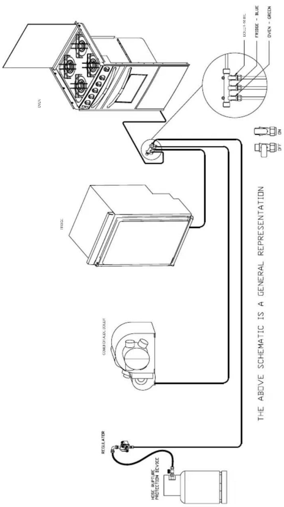
Note: Depending on the caravan model, the gas isolation tap for the water heater maybe located close to the appliance.
GAS
Gas
General information
Gas Cylinders
Bottled Liquified Petroleum Gas (LPG) is the most convenient portable source of fuel for your caravan. Make sure that heating and cooking appliances and the gas cylinders are switched off before you move the caravan.
Regularly check flexible gas hose, joints and connections for tightness.
Finally make sure that each gas appliance is working efficiently to the recommendations of the appliance manufacturers.
Only use gas bottle cylinders that are located within their dedicated position within the front gas bottle housing, never extend hose - hose lengths must not exceed 400mm.
Gas Hoses
A high pressure hose must be used with the regulator to connect to the gas bottle.
LPG cylinders i.e. Propane, Butane and Camping Gaz cylinders all have varying cylinder adaptor connections. It is important to check you have the correct hose and adaptor to suit your gas cylinders. Push on hoses are no longer permitted under the new regulations, The new high-pressure hoses have threaded connections and must be securely attached to the regulator and to the gas cylinder.
Ensure that there is a constant rise in the flexible gas hose between the gas cylinder outlet and the regulator elbow.

WARNING: Inspect flexible gas hose(s)ularly for deterioration and renew as necessary with the approved type, in any use no later than 5 years after the date of manufacture marked on the hose.

WARNING: Ensure hoses do not come entangled in door mechanism.
Cylinder compartment
All cylinder compartments have two universal plastic mouldings fitted to the floor of the compartment that are designed to fit both steel
and BP Gas Light cylinders and two universal support cradles with straps for retaining the bodies of the cylinders at mid to high level and two universal support cradles with straps for retaining the bodies of the cylinders at mid to high level.

WARNING: Ensure that the hose assembly is not under stress when connected to the cylinder.
Regulators
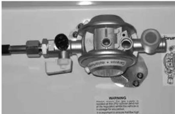
Your caravan is supplied with a wall mounted gas regulator plumbed inside the gas cylinder compartment. The regulator and all appliances work at a harmonised 30mb pressure, which work with Butane and Propane gas.
Pressure regulation system in this vehicle has a fixed working pressure of 30 mbar with a flow rate of 1.5 kg/h and complies with the requirements of EN 12864 annex D.
Note: Regulator valves and cylinder valves should always be in the 'OFF' position when towing and storage.

WARNING: When leaving the caravan any period of time or storage always turn the gas at the gas cylinder.
Note: Never allow modification of electrical or LPG systems and appliances except by qualified persons at an authorised Swift Group dealership.
DuoControl (Model Specific)
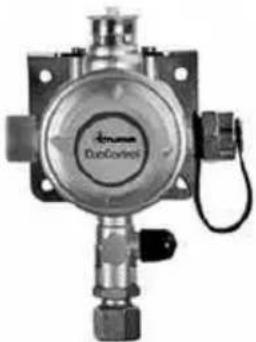
natural_image
Close-up of a metallic industrial sensor or valve device with no visible text or symbols on the body or side.The DuoControl combines the gas pressure regulator and the changeover valve in one unit for operation as a two-cylinder system. When the operating cylinder is empty, DuoControl automatically changes over to the reserve cylinder.
• Combines a gas pressure regulator and a changeover valve in one unit
• Automatically switches over to the reserve cylinder
- Complies with EN 13786
The Truma Drive Safe Regulator approved for en-route heating
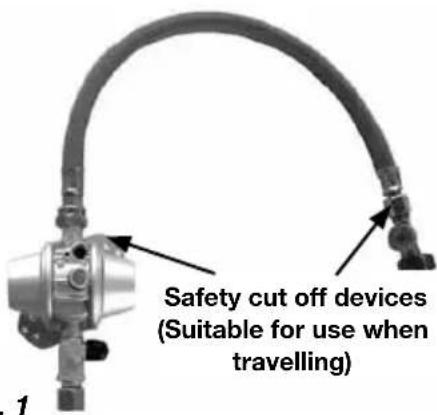
Fig. 1
Approved for en-route heating if your caravan has a factory fitted habitation en-route LPG heating system that can be used whilst travelling. Fig 1 shows the two safety valves features that are part of the system, these are there for your safety whilst using the system when travelling. When in use ensure all other gas appliances are separately isolated.
To use safety devices:
- Open cylinder valve
- Firmly press the hose rupture protection (green button) on the high pressure hose
- If necessary (eg. after a new installation or inadvertently striking the gas cylinder against the gas pressure regulation system), press the green rest button (crash sensor triggering element reset) on the regulator
⚠ WARNING: Isolate cylinders when re-fuelling
General
Regularly check flexible gas hose, joints and connections for tightness. Finally make sure that each gas appliance is working efficiently to the recommendations of the appliance manufacturers.
The LPG system should be inspected by a competent person.
Only use gas cylinders that are located within their dedicated position within the gas bottle housing, never extend the hose - hose lengths must not exceed 400mm.
We do not recommend the use of an inline LPG BBQ with the 1.2kg/H regulator when other LPG appliances are in use.
⚠ WARNING: Unless en-route heating is in use the LPG cylinder valve should be closed when driving.
TYPES OF GAS
Types of gas
Propane
Propane is supplied in red, or partly red bottles which have a female left hand threaded connector.
Scandinavian countries use the same connector.
Germany and Austria supply propane with a male connection.
Propane will work at temperatures as low as -40^ C and is therefore suitable for all winter caravanning.
Butane
Butane is supplied in the U.K. in green or blue cylinder.
All these have a male left hand thread
EXCEPT for Camping Gaz which has a special female right hand thread and Calor 7kg and 15kg and aluminium cylinders which have a special clip-on connection.
Continental cylinders usually have a male left hand thread similar to but not identical with U.K. butane.
Butane is only suitable for use at temperatures down to 2^ C and will not work below that.
Gas safety advice
⚠ WARNING: If you smell gas or suspect a leak or in the event of a fire and if it is safe to do so, isolate the gas appliances and turn off the gas bottles at the regulator. Evacuate the caravan and ventilate. Seek professional advice as to the cause of the leak.
⚠ WARNING: Inside outlet sockets shall only be used with dedicated appliances i.e. equipment supplied with the Touring Caravan. No gas appliances shall be used outside when connected to an inside socket
Facts about LPG
- LPG is not poisonous.
-
Bi-products are harmless.
-
There is danger if all air and oxygen were excluded.
- (Ventilation holes must be kept clear at all times).
- LPG has been given a smell by the manufacturers in order to identify leaks.
Awning Spaces LPG Appliance Exhaust
There is no danger of pollution of an enclosed awning space by the LPG exhaust from a refrigerator venting into it, as awning spaces are generally well ventilated.
Space heaters may produce sufficient exhaust to pollute the awning space, if it is totally enclosed, from a general comfort, smell and hygiene point of view. In the extreme case there could be a build up of carbon dioxide to a dangerous level.
Caravan owners are advised to allow some fresh air circulation in the awning space when such appliances are in use.
Precautions
a. Never look for a leak with a match. Always use a soap solution or its equivalent when testing connections. Do not operate any electrical apparatus whatsoever, especially light switches. If the leak is not obvious, the caravan should be evacuated and qualified personnel consulted.
b. Avoid naked lights when connecting or changing a cylinder.
c. Check the flexible hose frequently.
d. The gas is heavier than air and therefore sinks to the lowest point.
e. Keep bottle gas containers outside (and protected against frost). If they must be kept inside make sure they are well away from heat.
⚠ WARNING: Do not use appliances with a different working pressure to 30mbar.
⚠ WARNING: Maintain adequate spacing of combustible materials from sources of heat.
⚠ WARNING: Do not use independent portable gas appliances inside the vehicle. Cookers shall not be used as heaters
⚠ WARNING: A BBQ point inlet valve, if fitted, must only be used for the connection of portable LPG appliances.
⚠ WARNING: Always read individual appliance instructions
Connection
Ensure that the gas regulator hose is correctly connected to the gas cylinder in gas bottle compartment and that the hose connection is tight.
Gas bottles must be fully located, seated at the base of the bottles and restrained by the strap provided in the dedicated compartment position. Straps are positioned to suit 6kg Calor Lite cylinders.
⚠ WARNING: If using cylinders other than those recommended, the user must ensure these are adequately supported, ventilation openings must not be obstructed and the cylinders must not cause damage to other fixtures and fittings located in the compartment.
Open ended gas hoses must always be protected from dirt and insects.
Before turning on the gas supply at the regulator, ensure that all gas operated equipment in the caravan is turned off.
All gas equipment (except barbecue and some water heaters) is supplied through a central Gas Manifold System which has individual isolation taps for each appliance (Fig A), as follows:
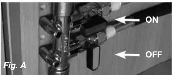
WHITE -Combi / Alde boiler
BLUE -Fridge
GREEN - Oven
Note: the external barbecue point is fed from the main feed through a built in integrated isolation valve. See schematic layout for details.
Note: In some installations the water heater is fitted with a separate isolation valve.
Ventilation
All ventilation complies with BS EN 721 and vents should not be obstructed in any manner as this could lead to insufficient fresh air. In this case the confined atmosphere becomes depleted of oxygen which could lead to dangerous levels of carbon dioxide (CO _2 ) build up leading to risk of asphyxiation.
The risks of carbon monoxide (CO) build up, which is a colourless, odorless and tasteless gas, will also be reduced with ventilation. Carbon monoxide is produced from incomplete combustion and should the CO detector be activated the cause of the incomplete combustion must be investigated prior to reusing the appliance in question.
Flue installations
All flue installations should be inspected once a year throughout their length for corrosion. Flues should be replaced if any sign of perforation is found. Ensure that the replacement is of an approved type.
Thermal insulation heating
Your caravan has been designed and manufactured to a grade 3 thermal insulation and heating level for specific climatic conditions and tested according to the procedure in EN1645-1.
The classifications are as follows:
Grade 1
A caravan with an average thermal transmittance (u) that does not exceed 1.7w/(m2k).
GAS FAULTS
Grade 2
A caravan with an average thermal transmittance (u) that does not exceed 1.7w/(m2k) and which can achieve an average temperature difference of at least 20k between inside and outside temperatures when the outside temperature is 0°C.
Grade 3
A caravan with an average thermal transmittance (u) that does not exceed 1.2w/(m2k) and which can achieve an average temperature difference of at least 35k between inside and outside temperatures when the outside temperature is -15°C.
GAS
| Fault Cause Remedy | ||
| Hob does not light | No gas | Check level of gas in the cylinderCheck gas cylinder valve is onCheck gas taps are onPurge systemRefer to hob manufacturers instructions |
| Air in pipe | ||
| Oven does not light | No gas | Check level of gas in the cylinderCheck gas cylinder valve is onCheck gas taps are onPurge systemRefer to oven manufacturers instructions |
| Air in pipe | ||
| Combi boiler or Alde appliance will not light. | No gas | Check level of gas in cylinderCheck gas cylinder valve is onCheck gas taps are onCheck exhaust outlet is clear |
| Over gassed | Turn off appliance, wait 2 minutes and try againPurge systemRefer to space heater or boiler manufacturers instructions | |
| Air in pipe | ||
| Fridge does not light | No gas | Check level of gas in the cylinderCheck gas cylinder valve is onCheck gas taps are onPurge systemRefer to fridge manufacturers instructions |
| Air in pipe | ||
The electrical system
General Information
It is strongly advised that the mains installation is inspected periodically to ensure safe use. The IET (BS7671) wiring regulations recommend that mains installations in touring caravans are re-inspected every 3 years. The National Caravan Council lists the qualifications necessary to perform this inspection, but an NICEIC approved contractor is probably the first choice.
On arrival at the campsite
- Disconnect hitch and 13 pin plug from the towing vehicle.
- Place the 13 pin plug in the holder provided to prevent damage.
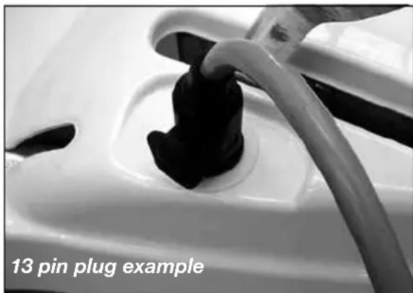
natural_image
Close-up of a car plug being inserted into a white container, with a 13-pin plug example noted below (no other text or symbols)- Check the suitability of the supply, is it AC or DC, is the voltage and frequency correct.
- Ensure that there is a proper earth (3 pin socket outlet).
- If in doubt consult site staff.
- Make sure that the supply from the site is switched off.
- Make sure that the charger switch on the PSU is switched off.
- Lift the cover on the electricity inlet on the caravan, and insert the connector on the flexible supply cable.
- At the site supply point, connect the other end of the supply cable to this using the socket provided.
- Switch on the main switch at the site supply point.
Care point: It is good practice to test the RCD (Residual Current Device) in the PSU before switching on. There is a test button on the RCD to test the lever, put the lever in the up position (on) before testing.
Care point: As with the RCD it is good practice to check the Miniture Circuit Breaker (MCB) in the PSU. Switch all to the on position (lever up). If any do not stay up then there is a fault.
On departure from the campsite
- Switch off supply from the site, disconnect the cable at both ends.
- Switch off RCD.
⚠ WARNING: Current consumption in the caravan must not exceed 16 amps or the pitch permitted maximum if this is less than 16 amps.
Overseas connection
- Connection to a mains voltage overseas requires particular attention.
• Overseas supplies can be of reverse polarity. - Reverse polarity results in equipment not necessarily being isolated when turned off, reverse polarity indicator on the PSU will light in the event of reverse polarity.
- The only sure way to make equipment safe is to unplug it.
- It is useful to have a means of checking polarity when overseas.
- If it can be achieved then connect live to live, and neutral to neutral to achieve full electrical protection.
⚠ WARNING: Never allow modifications of electrical or LPG systems and appliances except by qualified persons.
13 PIN CONNECTION
13 pin connection
When using the 13 pin connector system for the first time it is worth taking a few minutes to familiarise yourself with the basic features of the connectors.
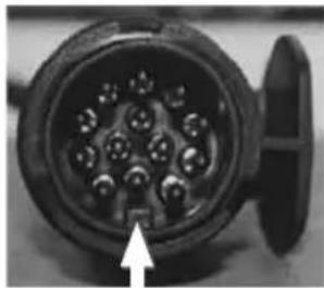
natural_image
Close-up of a black electrical connector with multiple pins and a white arrow pointing to the bottom (no text or symbols visible)Fig. 1 - Correct alignment
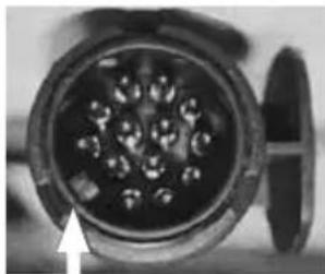
natural_image
Close-up of a mechanical component with internal spherical holes and a white arrow pointing to it (no text or symbols visible)Fig. 2 - Incorrect alignment
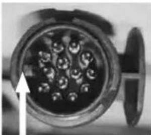
natural_image
Close-up of a cylindrical electronic component with multiple pins, no visible text or symbolsFig. 3 - Incorrect alignment
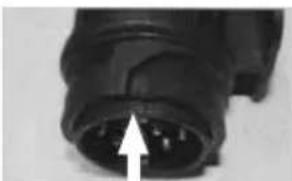
natural_image
Close-up of a black electrical connector with a white arrow pointing to the pin area (no text or symbols visible)Fig. 4 - Alignment marks
The important difference with the new 13 pin plug, when compared to the old 12N/S type, is that the plug has an inner ring assembly that is independent from the outer body. Under normal circumstances the inner ring and the outer body will be locked in one position (see fig 1).
When the plug is first inserted in the socket body ensure that the locating protrusion (key) matches the groove (keyway) in the socket body. The outer body can then rotated a full 90 degrees clockwise until a click is felt or heard, at this point the cover flap can be allowed to fall over the circular surface of the plug top.
To remove the plug it is important to rotate the outer body a full 90 degrees anti-clockwise, again until a click is heard or felt before withdrawing the plug from the socket. This will ensure that the inner and outer parts of the plug are returned to a locked condition.
If the connector is not fully rotated anti-clockwise prior to removing it from the socket it is possible that the inner ring will become 'floating' and may result in a condition where the protrusion will be incorrectly aligned (see fig 2 & 3).
If this situation does occur then it can be corrected by entering the edge of the protrusion on the plug into the groove in the socket (fig 8) and rotating the plug body anti-clockwise until a click is felt. This process will re-establish the lock between the inner and outer parts allowing the correct insertion of the plug into the socket.
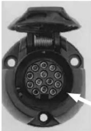
natural_image
Close-up of a black automotive electrical connector with multiple pins and mounting holes (no visible text or symbols)Fig. 5 - Socket body (containing female socket terminals) fitted to the car
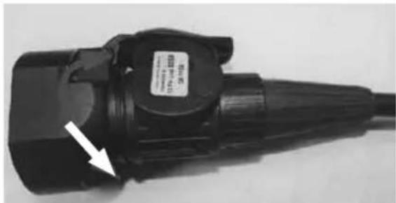
natural_image
Close-up of a black electric vehicle charging plug with a white arrow pointing to the tip (no visible text or symbols)Fig. 6
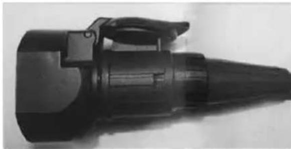
natural_image
Black mechanical component with tapered shaft and handle (no visible text or symbols)Fig. 7
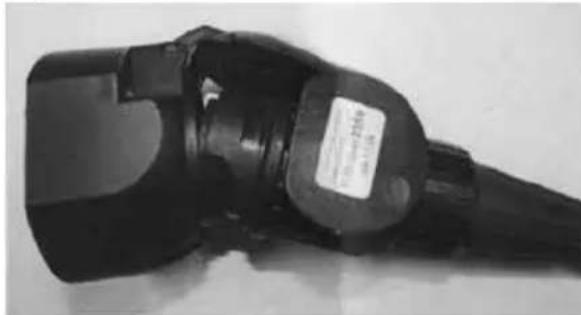
natural_image
Close-up of a black electrical plug with a label, no visible text or symbols on the body.Fig. 8
Plug inner ring (containing male pin terminals fitted to the caravan)
Plug outer body with locating groove and hood fitted to the caravan)
Fig.9
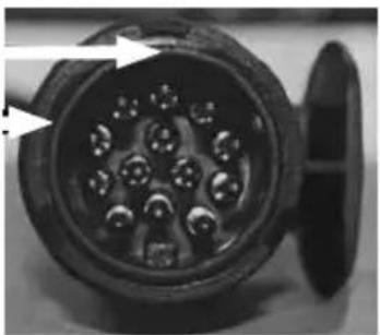
natural_image
Close-up of a black electrical connector with multiple pins and a side outlet (no visible text or symbols)230V mains electrical equipment power consumption
Note: It is possible that the 230v mains electrical equipment may not all operate simultaneously. A typical UK site mains hook up point provides a maximum output of 10 amps and on some continental sites the available output may be as low as 5 amps. If your loading exceeds the site supply it may trip the site circuit breaker. Please check the available mains supply with your site operator.
Similarly loadings on each circuit breaker within the caravan should be observed. A label positioned close to the MCB's (Miniture Circuit Breakers will identify which appliances within the caravan are fed from which MCB. Consulting the typical appliance consumption figures table in conjunction with this label, will give an indication of which appliances can, and cannot, (site supply allowing), be operated simultaneously.
natural_image
Close-up of a black electrical connector with multiple pins and a side outlet (no visible text or symbols)Wiring of connecting cable and caravan mains inlet
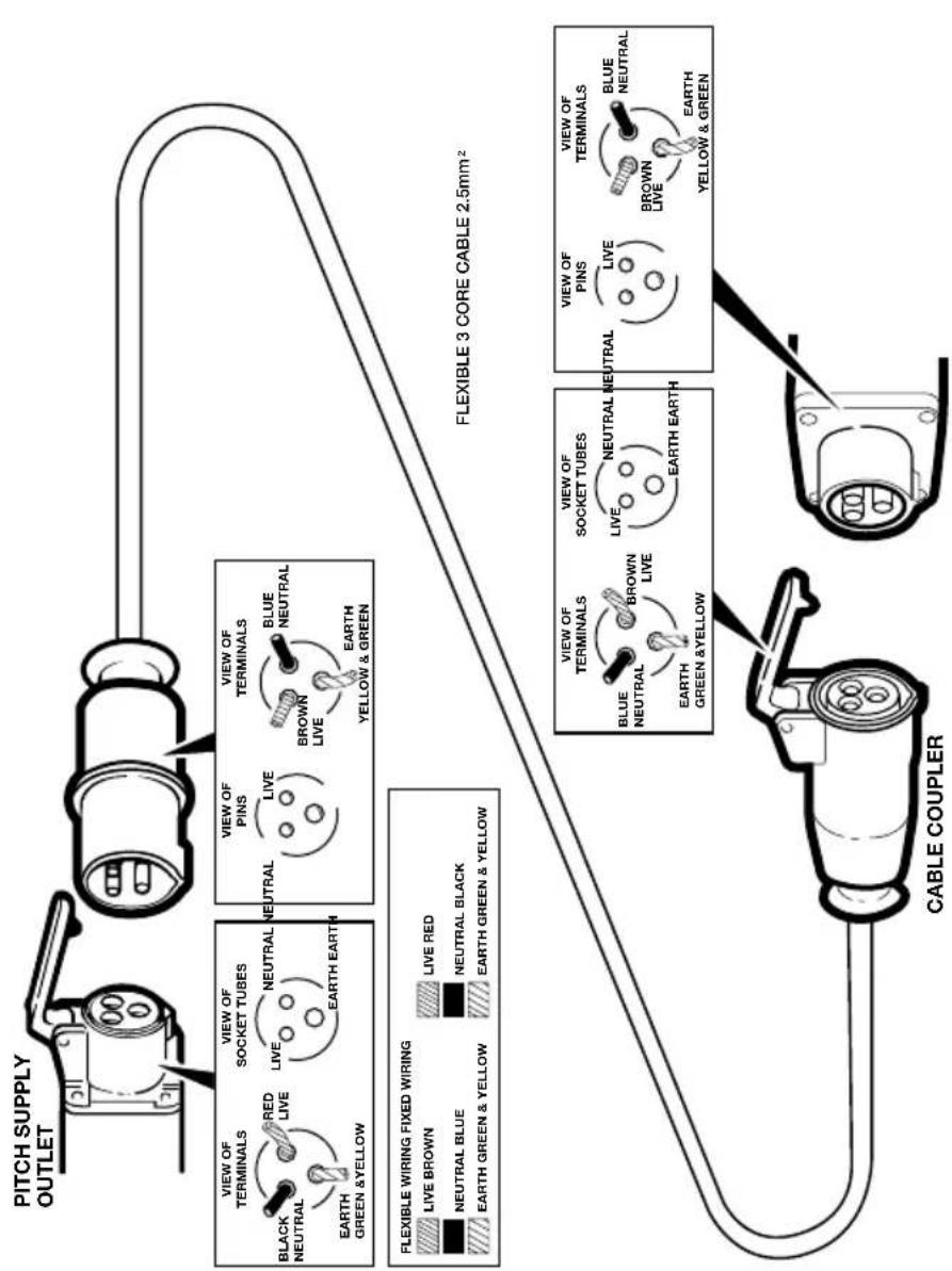
The legal length of the mains inlet cable is 25 ± 2 metres. When in use it must be fully uncoiled and protected from traffic.
Typical appliance consumption figures
| Appliance/ Item | 230 Volt 12 Volt LP Gas | ||||
| Watts Amperes W | Watts Amperes grams/hour | ||||
| Thetford Refrigerator 140 W 0.6 amp Only when towing 13 g/h | |||||
| Dometic Refrigerator 190 W 0.8 amp Only when towing 16 g/h | |||||
| Truma Combi 4 kw Heating system 900 / 1800 W 3.9 / 7.8 amp 13 W 1.1 amp | (avg) | 320 g/h | |||
| Truma Combi 6 kw Heating system 900 / 1800 W 3.9 / 7.8 amp 13 W | 1.1 amp | (avg) | 480 g/h | ||
| Alde Heating System | 1050 / 2100 / 3150 W | 4.6 / 9.1 / 13.7amp | 12W | 1.0 amp | 245 - 460 g/h |
| Microwave (factory fit) | 1000 - 1270 W | 4.3 - 5.5 amp | Not applicable | Not applicable | |
| Cooker hob burners | Not applicable | Not applicable | 70 - 161 g/h | ||
| Cooker Electric Hotplate | 850W | 3.7 amp | Not applicable | Not applicable | |
| Grill | Not applicable | Not applicable | 117 g/h | ||
| Oven | Not applicable | Not applicable | 125 g/h | ||
| Battery Charger | 690 W 3.0 amp Not applicable Not applicable | ||||
| 12V LED Lights(each, depending on size of light) | Not applicable | 0.4W - 6.1W | 0.05 amp - 0.5amp | Not applicable | |
| Pressure switched pump | Not applicable | 48 W | 4.0 amp | Not applicable | |
Note: These are approximate figures for guidance only, and are subject to changes in specification. The figures show energy consumption
when an item or appliance is operating - ie. a light is illuminated, or a heating system is providing space heating or water heating. Appliances
which feature LCD or illuminated control panels can have a low current consumption when in stand by mode, or have a constant low current
draw in the background to run their displays and electronic systems - these figures are typically 0.4 amps or less, for each applicable item.
These electronic items can in most cases are switched off individually, or, use of the System Shutdown button on the power supply unit isolates all of these items.
ELECTRICS
EC444/EC445/EC455 Power Control System 80
Control Panel Operation 83
Residual Current Device & Miniature circuit breakers.... 84
Battery charger....85
Leisure Battery 85
12 Volt DC Fuses.... 88
Electrical faults....91
Technical Data & Approvals 94
Thetford battery box 95
Battery installation 96
Solar panel connection point 97
Generator usage 98
Habitation relay....98
Exterior 230v socket....99
EC444 / EC445 / EC455 Power control system
1. Introduction
This section of the handbook will guide you through the operation of the electrical system. Further technical details are contained in section 3 from www.sargentltd.co.uk
For the safe operation of all electrical equipment within your Leisure Vehicle it is important that you read and fully understand these instructions. If you are unsure of any point please contact your dealer / distributor for advice before use.
The system has a number of key components that you will need to be familiar with before attempting to use the system, these are:
- The EC series Power Supply Unit (PSU) a combined mains consumer unit and 12V controller located in the front locker or bed box area.
On locker mounted caravan versions this unit also contains the provision for the Radio/CD head unit. The EC400 / EC450 series of power supply units include the EC400 range (horizontal units) and the EC450 range (vertical units), further details are contained later in this document.
• The EC series Control Panel (CP)
- a remotely located user control panel used to turn circuits on and off and to display battery and water tank information. This panel uses simple straightforward controls and reliable data communication to the PSU.
- Road Light Fuse Box
This small unit, which is unique to caravans, is located in the front bed box. The unit houses fuses for the road lighting circuits and supplies from the tow vehicle, and also has connectors for the optional alarm system and Automatic Trailer Control (ATC) unit.
2 Using the System
The PSU is located in the front offside locker area or front bed box in caravans.
2.1 Power Supply Unit - Models
A number of different PSU versions are used within the system. The operation of each model is very similar and is detailed below.
EC444 Sprite, Challenger Sport and Eccles Sport
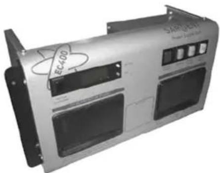
natural_image
Exterior view of a silver industrial control unit with visible circuit breakers and a circular logo (no readable text or symbols beyond branding)EC445 Challenger SE and Eccles Sport SE
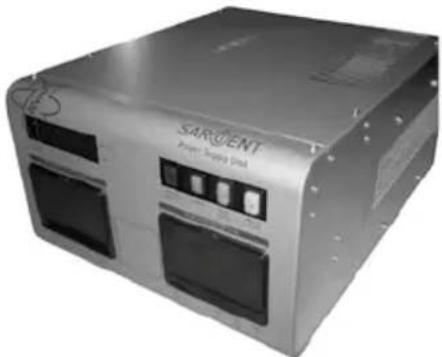
natural_image
Exterior view of a SARGENT power supply unit device (no visible text or symbols on the device body)EC455 Conqueror and Elite
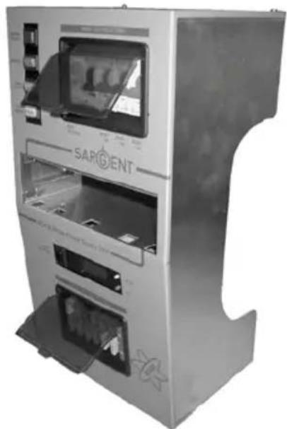
natural_image
Exterior view of a modern SARCENT vending machine (no visible text or symbols on the device itself)2.2 Power Supply Unit - Component Layout
| 230V Components | ||
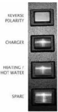 | Space heater /Water heater installations | Red indicator – Reverse polarity indicator, lights up when the 230V supply polarity is reversed. |
| REVERSE POLARITY | Green push switch – Charger switch, this switch turns the 12V battery charger on or off. “In” is on “out” is off. | |
| CHARGER | Amber push switch – Combi or Alde boiler, this switch turns the 230V supply to the combination heater / central heating system on or off. In is on out is off. | |
| K3GA | ||
| SPACE HEATER | ||
| WATER HEATER | White - Spare | |
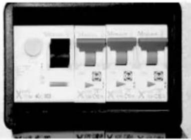 | Black lever switch, far left – Residual Current protection Device (RCD) and main 230V on / off switch. | |
| Yellow button, far left – RCD test button. | ||
| Red lever switches, right – 3 x 10A Miniature Circuit Breakers (MCB). Please note that installations with a 3KW Alde heating system will have 2 x 10A and 1x16A MCB’s. | ||
| 12V Components | |
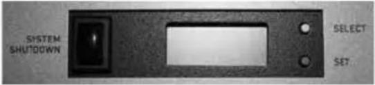 | Black push switch, far left – System shutdown switch, this switch turns the power control system on or off. In is on out is off. |
| Yellow push button, top right – Select button, this button is used to scroll through the display items on the LCD screen. | |
| Red push button, bottom right – Set button, this button is used to change the setting of the displayed item on the LCD screen. | |
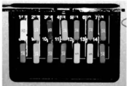 | 12V DC circuit protection fuses.Fuse number 1 is top left;Fuse number 14 is bottom, right.See section 3.5 for full fuse allocation details. |
EC444/EC445/EC455 POWER CONTROL SYSTEM
2.3 Activating the System
The EC400 / EC450 system has a shutdown feature that should be used when the vehicle is in storage or is not being used for long periods of time. This allows the leisure electronics to be turned off when not required to save battery power. When in the off state the alarm and tracking system supplies are still active, most other supplies are turned off.
Before using the system please ensure the shutdown switch is in the system on position (button in).
2.4 Connecting to the Mains 230V supply and Safety checks
For your safety it is IMPORTANT that you follow these connection instructions each time your Leisure Vehicle is connected to a mains supply. This section assumes that the system is complete and that a Leisure battery has been installed (see 3.4).
a. Ensure suitability of the Mains Supply. Your Leisure Vehicle should only be connected to an approved supply that meets the requirements of BS7671 or relevant harmonised standards. In most cases the site warden will hold information regarding suitability of supply. If using a generator you also need to comply with the requirements / instructions supplied with the generator. Please note that some electronic generators may not be compatible with your leisure system. Further generator operational information is contained elsewhere in this manual.
b. Switch the PSU internal Power Converter OFF. Locate the green 'Charger' power switch on the PSU and ensure the switch is in the off position (button out) before connection to the mains supply.
c. Connect the Hook-up Lead. Firstly connect the supplied hook-up lead (orange cable with blue connectors) to the Leisure Vehicle and then connect to the mains supply.
d. Check Residual Current Device operation. Locate the RCD within the PSU and ensure the RCD is switched on (lever in up position). Press the 'Test' button and confirm that the RCD turns off (lever in down position). Switch the RCD back to the on position (lever in up position). If the test button failed to operate the RCD see section 3.10.
e. Check Miniature Circuit Breakers. Locate the MCB's within the PSU (adjacent to the RCD) and ensure they are all in the on (up) position. If any MCB's fail to 'latch' in the on position see section 3.10.
f. Turn the PSU ON. Locate the black ‘Shutdown’ button and ensure it is in the on position (press button in). Locate the green ‘Charger’ switch on the PSU and turn to the on position (press button in). The charger switch will illuminate when turned on.
g. Check correct Polarity. Locate the 'Reverse polarity' indicator on the PSU and ensure that the indicator is NOT illuminated. If the indicator is illuminated see section 3.10.
h. Check operation of equipment. It is now safe to operate the 12v and 230v equipment.
2.5 Control Panel - Component Layout
Depending on your type of caravan the control panel will vary in specification.
Not all features are present in all vehicles. Please refer to the following diagrams to identify your control panel.
EC451 - Caravans with water tanks
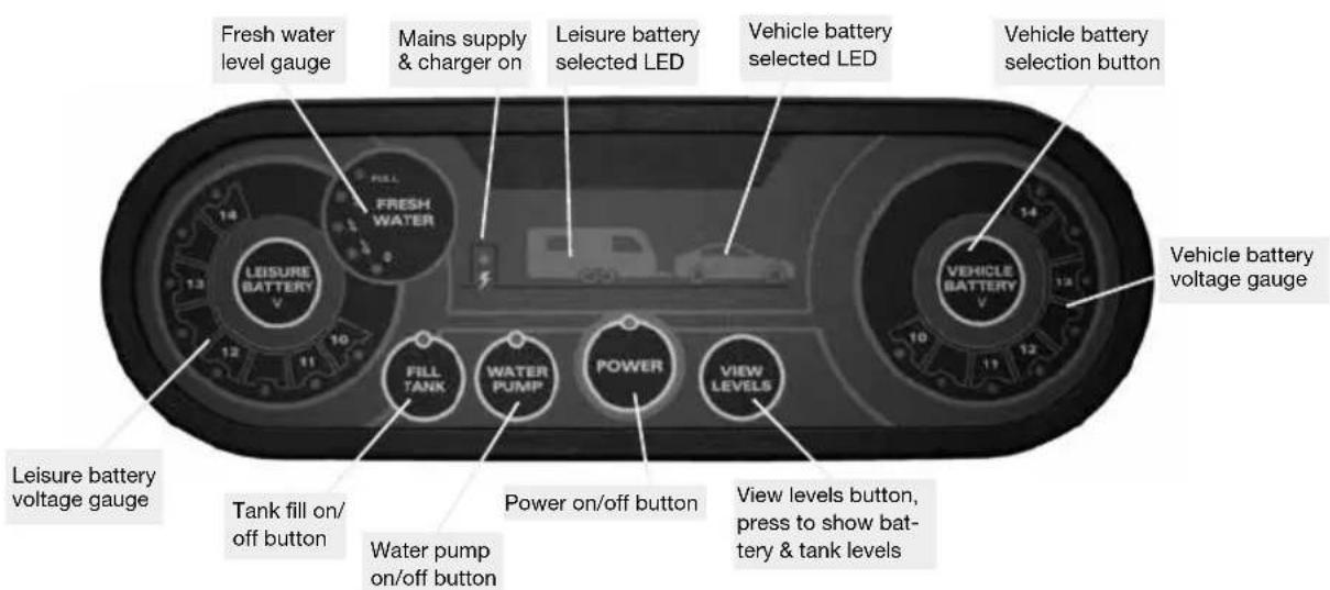
EC442 - Caravans without water tanks
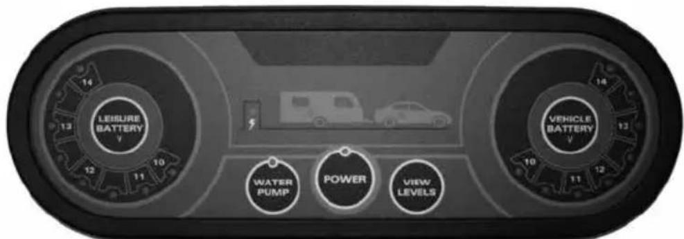
2.6 Control Panel Operation
- Power Button. Press the power button to turn the leisure power on. Press the button again to turn the power off. The adjacent LED will illuminate when the power is on, and also the voltage of the selected battery will be displayed on the voltage gauge.
- Pump Button. With the power on, press the pump button to turn the water pump on. Press the button again to turn the pump off. The adjacent LED will illuminate when the pump is on, and also the level of the water tank will be displayed on the water gauge.
- View Levels. To display the battery voltage levels and the water tank levels on the control panel gauges, press the levels button. The display will remain illuminated for 10 seconds. It is possible to lock the display 'on' to allow continuous display. This can be achieved by pressing and holding the view
levels button for 2-3 seconds until you hear a beep. To turn this locked feature off, either press and hold the view levels button again for 2-3 seconds or turn the power off and back on.
- Battery Select. By default, the leisure battery is selected as the power source if no mains supply is present, or as the battery to be charged when the mains supply is available. To change the selected battery, press the vehicle battery select button. The selected battery is indicated by an LED adjacent to the caravan or car logo.
- Mains on indication. When connected to a 230v supply the LED with a "lightning strike" shown will be illuminated.
EC444/EC445/EC455 POWER CONTROL SYSTEM
- Charging when the vehicle engine is running. When the vehicle engine is running both the vehicle battery and the leisure battery LED's will flash in unison to indicate that they are connected together and are being charged by the vehicle.
- Tank Fill Button. For some caravans, with the power on, press the tank fill button to turn the external filler pump on or off. Please ensure you switch the fill button off when the external tank is empty to prevent damage to the pump.
2.7 Operation while driving
The EC system is designed to shutdown parts of the system while the engine is running.
This is to meet Electro Magnetic Compatibility (EMC) regulations and to ensure the safe operation of the caravan. This is indicated by the two battery LED's flashing together.
Please ensure the system shutdown switch on the PSU is in the "on" (button in) position before driving (see 2.3). This will ensure the electronic system is active and will therefore be able to control the charging process, supply the refrigerator and monitor other system circuits.
3. System Technical Information
The following section provides further technical information relating to the electrical system. You can also access the supporting technical manual from www.sargentltd.co.uk
3.1 Residual Current Device & Miniature Circuit Breakers
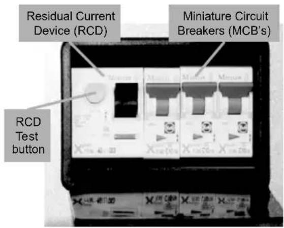
The Residual Current Device (RCD) is basically provided to protect the user from lethal electric shock. The RCD will turn off (trip) if the current flowing in the live conductor does not fully return down the neutral conductor, i.e. some current is passing through a person down to earth or through a faulty appliance.
To ensure the RCD is working correctly, the test button should be operated each time the vehicle is connected to the mains supply (see section 2.4)
The Miniature Circuit Breakers (MCB's) operate in a similar way to traditional fuses and are provided to protect the wiring installation from overload or short circuit. If an overload occurs the MCB will switch off the supply. If this occurs you should investigate the cause of the fault before switching the MCB back on.
The following table shows the rating and circuit allocation for the three MCB's
| MCB Rating Output wire | colour Description | |
| 1 10 Amps White 230v Sockets | ||
| 2 10 Amps White | (Yellow for heater) | Extra 230v Sockets / Space Heater |
| 2 16 Amps Yellow Alde heating (EC470 PSU only) | ||
| 3 10 Amps Black | (Blue for water heater) | Fridge / Water heater / 12v Charger (internally connected) |
3.2 Battery Charger
The EC444 / EC445 / EC455 system incorporates an intelligent three-stage battery charger / power converter.
During stage 1 the battery voltage is increased gradually while the current is limited to start the charging process and protect the battery. At stage 2 the voltage rises to 14.4V to deliver the bulk charge to the battery. When the battery is charged, the voltage is decreased at stage 3 to 13.6V to deliver a float charge to maintain the battery in the fully charged state. The charger can be left switched on continuously as required.
The battery charger / power converter also provides power to the leisure equipment when the mains supply is connected. This module supplies DC to the leisure equipment up to a maximum of 25 Amps (300 Watts), therefore the available power is distributed between the leisure load and the battery, with the leisure load taking priority as per the following example:
| Lesiure Load Available | ble power for battery charging |
| 5A 20A | |
| 10A 15A | |
| 15A 10A | |
| 20A 5A |
⚠ WARNING: Under heavy loads the Charger case may become hot. ALWAYS ensure the ventilation slots have a clear flow of air. Do not place combustible materials against / adjacent to the Charger
3.3 Leisure Battery
a. Type / Selection
For optimum performance and safety it is essential that only a proprietary brand LEISURE battery is used with a typical capacity of 75 to 120 Ah (Ampere / hours). A normal car battery is NOT suitable.
This battery should always be connected when the system is in use. The PSU is configured to work with standard lead acid leisure batteries, and in most cases is also compatible with the latest range of Absorbed Glass Matt (AGM) batteries. Before fitting non-standard batteries please check that the charging profile described in 3.2 is suitable for the type of battery by referring to the battery documentation or battery manufacturer.
The battery feed is fitted with an inline fuse between the battery and the electrical harness, and is usually located immediately outside the battery compartment or within 500mm of the battery. The maximum rating of this fuse is 20A per battery.
EC444/EC445/EC455 POWER CONTROL SYSTEM
b. Installation & Removal
Always disconnect the 230v mains supply and turn the PSU green charger switch to the off position (button out) before removing or installing the battery.
When connecting the battery, ensure that the correct polarity is observed (black is negative [-] and red is positive [+]) and that the terminals are securely fastened. Crocodile clips must not be used.
⚠ WARNING: Explosive gases may be present at the battery. Take care to prevent flames and sparks in the vicinity of the battery and do not smoke. Switch off all appliances and lamps before connecting or disconnecting the leisure battery.
c. Operation / Servicing
Under normal circumstances it should not be necessary to remove the battery other than for routine inspection of the terminals and “topping up” of the battery fluid where applicable. Please see instructions supplied with the battery.
Note: Do not over discharge the battery. One of the most common causes of battery failure is when the battery is discharged below the recommended level of approximately 10v. Discharging a battery below this figure can cause permanent damage to one or more of the cells within the battery.
12V Operation of Electrical Items
Most appliances within your caravan are designed to function when supplied with a 12V feed, either from a leisure battery or the on-board charger.
However, customers should note that some items may have limited functionality when the battery is in a lower voltage state (i.e. circa 10V). The Swift Group makes every effort when specifying components to operate at low voltages, but is not responsible if a component fails to work at lower voltages.
Components that are typically affected by low battery voltage include, but are not limited to, the pump, the radio and some lights which require higher voltages for start-up.
To prevent over discharge, the EC400-450 system incorporates a battery protect circuit that warns the users and then disconnects the batteries when they fall below set values.
If the power is turned on and the leisure battery level falls below 9V a warning beep will be heard and the leisure battery gauge 10V LED will flash. To cancel the warning, press the levels button.
If the power is turned on and the vehicle battery level falls below 10.9V a warning beep will be heard and the vehicle battery gauge 10V LED will flash. To cancel the warning, press the levels button.
These warnings will not be repeated unless the power switch is turned off and on again. This is to ensure the warning does not become a nuisance.
| Battery Voltage cut off Action | after cut off Notes | ||
| Vehicle 10.9v | Battery selection is | changed from Vehicle battery to Leisure battery. If the leisure battery is below 9v then a further warning will occur (see below). | This cut off level is designed to protect the vehicle battery from over discharge. The 10.9v level ensures there is sufficient power in the battery to run the vehicle electronics and start the vehicle. This cut off only applies to power drawn from the battery by the leisure equipment; it will not protect the battery if you leave vehicle circuits switched on, such as the road lights. |
| Leisure 9v | Power is turned off | This is an emergency cut off | level to protect the battery from severe damage. You should not rely on this cut off level during normal operation, but manage your power consumption to a discharge level of 10v.This cut off only applies to power drawn from the battery by the leisure equipment that is controlled by the control panel power switch; it will not protect the battery from discharge by permanently connected equipment. |
3.4 12 Volt DC Fuses
⚠ WARNING: When replacing fuses always replace a fuse with the correct value. NEVER replace with a higher value / rating as this could damage the wiring harness. If a replacement fuse ‘blows’ do not keep replacing the fuse as you could damage the wiring harness. Please investigate the fault and contact your dealer.
⚠ WARNING: Only fit fuses that are manufactured to ISO 8820-3:2010. Using poor quality imitations is dangerous.
The following table shows the fuse allocation for the 15 fuses fitted to the PSU. Please note that fuses are dependant on PSU versions, so not all fuses may be present.
| Fuse Rating Fuse colour | Description | ||
| 1 20 | Amps Yellow Not used in caravan application | ||
| 2 15 | Amps Blue Not used in caravan application | ||
| 3 7.5 | Amps Brown Not used in caravan application | ||
| 4 15 | Amps Blue Not used in caravan application | ||
| 5 10 | Amps Red Extractor | Fans / Combination | Heating Systems |
| 6 10 | Amps Red 12V Sockets / TV Amp / Radio (caravan radio supply) | ||
| 7 10 | Amps Red Front Internal Lighting | ||
| 8 10 | Amps Red Water Pumps / Toilet | ||
| 9 15 | Amps Blue Not used in caravan application | ||
| 10 | 10 Amps Red | Not used in caravan application | |
| 11 | 10 Amps Red | Bathroom lights | |
| 12 | 5 Amps | Tan | Electronics / Fridge / Alarm |
| 13 | 5 Amps | Tan | Oven Ignition / Water Heater (where applicable / Separate water heater) |
| 14 | 10 Amps Red | Rear Internal Lights | |
| 15 | 25 Amps | White Charger | (fitted internally to PSU) |
The following table shows details of the fuse(s) located at the Leisure battery. See also 3.3A
| Fuse | Rating | Fuse colour | Description |
| Battery 1 | 20 Amps | Yellow | Fuse remotely located near battery |
The following table shows details of the fuse(s) located at the Road Light fuse box, on the front wall inside the front bed.
| Fuse Rating Fuse colour Description | ||
| 1 20 Amps Yellow Fridge Supply 12V | ||
| 2 5 Amps Tan Left Hand Tail Lights | ||
| 3 5 Amps Tan Right Hand Indicators | ||
| 4 5 Amps Tan Fog Lights | ||
| 5 Spare location | ||
| 6 20 Amps Yellow Car Battery Supply 12V | ||
| 7 5 Amps Tan Right Hand Tail Lights | ||
| 8 5 Amps Tan Left Hand Indicators | ||
| 9 7.5 Amps Brown Stop Lights | ||
| 10 5 Amps Tan Reverse Lights |
3.5 System Status and Configuration display
Depending on specification, the PSU may feature an LCD display and two control buttons that allow system information to be viewed or settings changed.
Press the top yellow 'select' button to change the item being viewed. Press the bottom red 'change' button to change the setting. Both buttons work on a continuous loop, so if you want to return to an item or setting keep pressing the button until the required item is reached.
3.6 Water System Operation
The control panel pump button operates the internal (onboard) water pump. This pump will draw water from the internal (onboard) water tank (if fitted) or the external water inlet, depending on the position of the manual supply selector valve.
The system also incorporates a separate powered water inlet that can be used with an external filler pump to fill the internal (onboard) water tank (if fitted).
The water level system incorporates a level warning system to warn users when the fresh water level drops below 25%. If the water pump power is turned on and the fresh water level drops to below 25% a warning beep will be heard and the fresh gauge empty LED will flash. To cancel the warning, press the levels button.
If the water pump power is turned on and the waste water level rises to full (100%) a warning beep will be heard and the waste gauge full LED will flash. To cancel the warning, press the levels button. These warnings will not be repeated unless the water pump power switch is turned off and on again.
This is to ensure the warning does not become a nuisance.
3.7 Warnings and Alerts
If the vehicle engine is started whilst the caravan is connected to the 230v supply, a warning beep will be heard. This is to warn you to remove the 230v supply before driving away.
When the vehicle engine is running both the vehicle battery and the leisure battery LED's will flash in unison to indicate that they are connected together and are being charged by the vehicle.
Low water level and waste tank, if the fresh water level drops to below 25% a warning beep will be heard and the fresh gauge empty LED will flash. To cancel the warning, press the levels button. If the waste water level rises to full (100%) a warning beep will be heard and the waste gauge full LED will flash. To cancel the warning, press the levels button.
Low voltage warning and cut off, if the power is turned on and the leisure battery level falls below 9V a warning beep will be heard and the leisure battery gauge 10V LED will flash. To cancel the warning, press the levels button. If the power is turned on and the vehicle battery is selected (being used) and the level falls below 10.9V a warning beep will be heard and the vehicle battery gauge 10V LED will flash. To cancel the warning, press the levels button.
3.8 Common Fault Table
| Fault Possible | Cause Proposed Fix | |
| No 230 volt output from PSU | Connecting lead between the site and Leisure Vehicle not connected | Check and connect lead as per 2.4C |
| RCD switched off Reset RCD as per 2.4D | ||
| RCD not operating correctly Check supply polarity; if the RCD continues to fail contact your Dealer as there is probably an equipment or wiring fault. | ||
| MCB switched off Reset MCB by switching OFF (down position) then back ON (up position), if the MCB continues to fail contact your Dealer as there is probably an equipment or wiring fault. | ||
| No or deficient supply from site | Contact site Warden for assistance | |
| Other fault Contact your Dealer | ||
| Reverse Polarity light is illuminated on PSU | Mains Supply reversed? The reverse polarity light is designed to illuminate when the Live and Neutral supply has been reversed / crossed over. If the light illuminates there is a problem with the site supply or the cable connecting the supply to your vehicle. The light is designed to work on UK electrical supplies (where the neutral conductor is connected to earth at the sub station). If you are using your vehicle outside the UK this light may illuminate when no fault exists. In these cases consult the site warden for advice. | |
3.8 Common Fault Table
| Reverse Polarity light is illuminated on PSU | Generator being used ‘The Reverse Polarity warning light is on when using my Generator’. This is a normal side effect when using some types of generator. Instead of connecting the neutral conductor to earth, some generators centre tap the earth connection making both neutral and live conductors 110v above earth. This 110v difference causes the neon polarity indicator to illuminate. In most cases it is still safe to use the generator, but please consult the generator handbook for further information. | |
| Control Panel Problems | Control Panel has no display Check batteries and fuses, turn PSU shutdown switch and charger switch on and ensure mains supply is connected. Check control panel connecting lead at PSU and behind Control Panel. Contact your Dealer | |
| 12v Power turns off Battery protect feature has operated to protect the Vehicle battery and or the Leisure battery. See 3.4C Engine has been started, all equipment has been disconnected to meet EMC requirements. See 2.7 | ||
| Control Panel locked / erratic function | Observe control panel handling instructions Control panel software may have crashed. Reboot control panel by turning off the PSU isolate switch. Wait 30 seconds then turn the switch back on. | |
| No 12 volt output from PSU | No 230v supply Check all above | |
| Charger not switched on Turn charge switch on, switch will illuminate | ||
| Battery not connected and / or charged | Install charged battery as per 3.4 | |
| Power button on control panel not switched to on | Turn power on at control panel | |
| Battery flat / Battery fuse blown | Recharge battery, check fuses, check charging voltage is present at battery | |
| Fuse blown Check all fuses are intact and the correct value fuse is installed as per fuse table | ||
| Equipment switched off / unplugged | Check equipment is switched on and connected to the 12v supply | |
| PSU overheated / auto shut-down operated | Reduce load on system. Allow PSU to cool down. PSU will automatically restart when cool. | |
| Other fault Contact your Dealer | ||
| Pump not working | Fuse blown Replace fuse with correct value as per fuse table. | |
| Pump turned off Turn pump on by pressing the pump button at the control panel. | ||
| Setting incorrect Both the internal and external pump feeds are controlled from the control panel. To alter the setting of the pump switch see section 3.8 Ensure the setting matches your desired requirement. | ||
3.11 Contact details
Sargent Electrical Services Limited, provide a technical help line during office hours. Please contact 01482 678981 if you require technical help. For out of hour support please refer to the tech support section of the Sargent web site www.sargentltd.co.uk
TECHNICAL DATA & APPROVALS
4 Technical Data & Approvals
4.1 Caravan Equipment –
| Outline Specification | ||
| INPUT 230v 230 Volts / 0 to 16 | Amps + / - 10% | |
| OUTPUT 230v RCD protected, | 3 x MCB outputs of 10A Separate switched channels for water heater, space heater and charger | |
| INPUT 12v 2 x 20A battery inputs via 2 x 4 way connectors | ||
| OUTPUT 12v 25A total output via multiple switched channels protected by 14 fused outputs | ||
| CHARGER Input 220-240 Volts | AC +/- 10%, Frequency 50 Hz +/- 6%, Current 3A max. DC Output 13.6 to 14.4 Volts nominal, Current 25 Amps max (300 Watts). Overall size (HxWxD) 50 x 250 x 135mm | Fixing centres 128*128mm 1.2kg |
| Signal INPUT 4 x Fresh water level, 1 x Engine running, plus multiple vehicle connections | Fresh water negative sensed | |
| Data IN / OUT CANBUS Data communication and power to Control Panel via 6 way connector | ||
| IP rating IP31 | ||
| Operating temperature Ambient | 0 to 35°Centigrade PSU case temperature with full load 65°C Max | Automatic shutdown and restart if overheated / overloaded |
4.2 Approvals
System: BSEN 1648-1, BSEN1648-2
compliant, BS7671: 2008 compliant
Residual Current Device: RCD 40A 30mA trip to BS EN 61008
Miniature Circuit Breakers: MCB's type C 6000A breaking capacity to BSEN 60898
Electro Magnetic Compatibility (EMC) directive 2004/108/EC Certificate CE20071224-1
Integrated Charger: BS EN 60335-1/2.29, 2006/95EC, IEC61000-3.2/3:1995, 1.
Low Voltage Directive: 2006/95EC TUV-014900-A1, EN55022, Class B, EN55024/Level 2.
The battery box
The Battery Box is intended to accommodate an auxiliary battery in your caravan. The Battery Box has a CE socket to connect to a 230 V power supply. Inside the Battery Box there is the option to fit several sockets and outlets.
⚠ WARNING:
- Use precaution when mounting the battery, as batteries contain acid liquids which can cause severe injuries and damage when handled incorrectly. Refer to the instructions on the battery.
- No smoking is allowed in the area of the Battery Box!
- Please note that the CE socket has a max of 16 amp.
- This product meets the latest version of the EN 1648 part 1 and 2 standard.
Before placing the battery inside the Battery Box, the battery should be placed in the Soft Tray and rested on the ground adjacent to the Battery Box. Carefully connect the electrical wires (the red cable attaches to the + pole and the black cable to the - pole of the battery).
Note: Incorrect connection of the cables will cause a short circuit with potential hazardous consequences.
After mounting the terminals, lift the battery together with the Soft Tray into the middle of the Battery Box compartment. Push the battery to the back of the Battery Box.
The battery is then secured by restraining straps (see figure A).
When attaching the 230 volt cable on the CE socket, the maximum recommended thickness of the cable is 10 mm. When closing the door, the attached cable is to be fed through the slot in the door. The maximum battery size that can be fitted is 225mm high (including terminals) x 175mm deep x 353mm wide. The depth and width dimensions include the rim around the bottom used for securing the battery.
Figure A
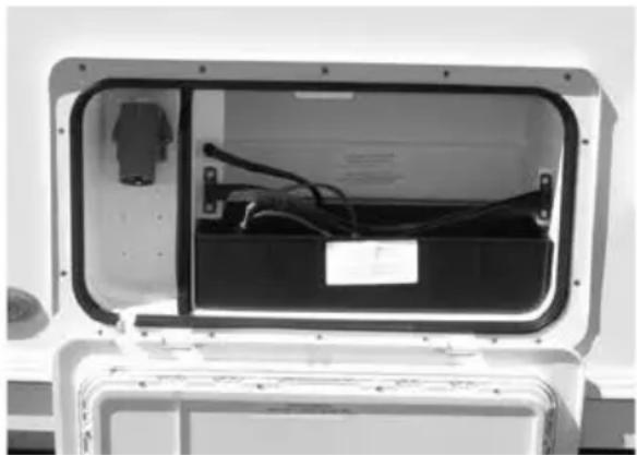
natural_image
Interior view of a white electronic device showing internal components and wiring (no visible text or symbols)Cleaning and maintenance
- Use protective clothing and glasses when handling a leaking battery, and avoid direct contact to the skin, eyes and respiratory organ.
- Should a battery leakage occur, please act according to the instructions supplied by the manufacturer of the battery. Act with caution as caustic substances are present in the battery.
BATTERY
- Always remove the battery and the power cable before carrying out any maintenance of the product.
- Before removing the clamps switch off all electrical and gas appliances.
- Use a soft cloth or sponge and a non-acid/abrasive detergent when cleaning the battery box or soft tray.
- To check if any acid is present in the soft tray or bag, simply press it softly. A strong smell from the soft tray may also indicate spilled acid. Always treat spilled battery acid as hazardous waste. Dispose of spilled battery acid according to the local and national regulations.
- Before the camping season or extensive travelling, check the soft tray or bag for faults and replace if necessary.
- The cleaning of the battery box and soft tray or bag should only be done after all power sources have been switched off, in order to prevent a hazardous situations.
Battery installation
Under normal circumstances it should not be necessary to remove the battery other than for routine inspection of terminals and ‘topping up’ if required.
⚠ WARNING: Explosive gases may be present at the battery. Take care to prevent flames and sparks in the vicinity.
Your caravan has been fitted with an in-line fuse between the battery terminal and caravan harness. It is recommended that the fuse rating fitted in this location does not exceed 20 amps.
⚠ WARNING: Switch off all electrical and gas appliances and lamps before connecting or disconnecting the battery. Smoking is prohibited around the battery compartment.
To preserve the life of your leisure battery and charger please observe the following:
- Do not leave all 12V appliances powered at the same time as this will drain your leisure battery more rapidly.
- If all 12V appliances must be powered together, ensure the battery is 'in-circuit' and that the battery charger is turned on.
- For optimum performance use the transformer/charger unit with a leisure battery attached.
Battery
It is recommended that a good quality rechargeable leisure battery is always in circuit when the system is in use.
A deep cycling heavy duty 12V battery should be purchased to provide power for lights and other electrical appliances.
A proprietary brand leisure battery with a minimum of 85 Amp capacity is recommended.
Note: 85 Amp batteries and above should be checked dimensionally before purchasing, to ensure fitment within the battery compartment, as brands vary in size.
It should be remembered that batteries suitable for the electrical demands of a caravan differ in design from those for use with a car, and whilst the system may operate with a car battery it is strongly recommended that only a leisure type battery, maintained in good condition is used. The battery should be kept topped up at all times if required.
Note: Some models may have more than one 12V socket fitted, the 6 Amps indicated is available from the 12V socket provided no other 12V socket is used at the same time.
Solar panel connection point (where supplied - model specific)
A connection point has been included in the caravan electrical harness to take a 12V supply from an aftermarket solar panel (or similar device), to the caravan leisure battery. The solar panel must provide a fused and regulated output in order to connect to this point. When fitted the connection point can be found inside the caravan adjacent to the battery box, in close proximity to the battery box fuse. Through the floor close to the battery box is a cable pass through, allowing a pair of wires from an externally located device to pass from exterior to interior to meet the connection point. This cable pass through will be capped both internally and externally with a cable entry gland.
A kit of parts is available from your caravan supplier which provides the mating half of the connection point. (The White rectangular connector found inside the caravan is a two way JST-LR type connector). For further assistance in identifying the connection, wire colours leading to the connector are detailed in the wiring schematic in your caravan service book.
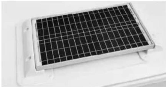
natural_image
Close-up of a solar panel array on a white base (no text or symbols visible)Factory fitted Solar Energy System
Depending on specification, your tourer may be fitted with a 40w solar panel and regulator. This solar panel and regulator may provide additional 12v power whenever sunlight is available to the panel, and this will be directed to the leisure battery whether the control panel is ON or OFF, and regardless of the position of the SYSTEM SHUTDOWN button. If a factory fitted alarm system is present, that alarm will in turn be able to use the leisure battery as a power supply. Conditions allowing, the system keeps the leisure battery 'topped up' during storage, and will provide a daily boost to the leisure battery when camping without a mains 230V supply.
Battery power
A 40w panel is capable of supplying up to 2.4 amps, +/- 1.5%.
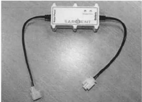
natural_image
Sargent device with two connected wires, no visible text or symbols on the device bodyRegulator
Unlike typical regulators, the 15575-R solar panel regulator has been specially designed to draw no power from the leisure battery when the solar panel is not generating power. This features is desirable especially in winter months when a normal regulator can gradually discharge the leisure battery.
Regulator operation
The regulator operates automatically, turning on and off as required to charge and maintain the leisure battery. When the solar panel is exposed to a source of sunlight the regulator starts to operate. When the voltage from the panel reaches a usable level, the Panel Output LED will flash indicating that the battery is being charged (see battery charging on next page). If insufficient power is being generated by the solar panel the regulator will turn off. The regulator checks the solar panel output every 30 seconds and turns on and off as required. On overcast days when the solar panel output is minimal the regulator can still deliver a small charge, and in this mode the LED's are not illuminated to conserve power.
Battery charging
If a leisure battery is fitted and requires charging the Charge Status LED will illuminate. Depending on the state of charge of the battery this LED will illuminate red for bulk charge (14.4V output) or green for float charge (13.6V output). It may take a few hours to several days to charge the battery depending on its state of charge. When the battery is fully charged the regulator will turn off to prevent overcharging of the battery. If the mains charger is turned on to charge the leisure battery this can also cause the solar panel regulator to turn off.
Power Supply Unit
The PSU does not need to be switched on (shutdown button in) for the solar panel to charge the battery, but if the PSU has an LCD display then this can be used to see the increase in battery voltage as the solar panel charges the battery. During caravan storage the PSU should be shutdown (shutdown button out).
Control Panel
When the solar panel is operating the voltage display on the leisure battery will increase if the loads placed on the battery are sufficiently light.
Maintenance and cleaning
The solar panel will require cleaning periodically in order to maintain the performance of the panel, a caravan, car shampoo or simple soap can be used; no abrasive cleaners should be used.
Generator usage
Caution should be used before connecting a generator to your caravan.

WARNING: Never start or stop the generator while electrical loads are connected and switched on. Start the engine, let it stabilise, then connect the electrical load. To stop engine, disconnect the electrical load and let engine stabilise before switching off.
Whilst some generators use invertor technology, others use a more basic principle to generate the 230v supply. Preference should be to choose a generator which produces a consistent sinusoidal wave form with accurate voltage control.
The reverse polarity warning light may illuminate when using a generator. This is a normal side effect when using some types of generator. Instead of connecting the neutral and live conductors 110v above earth. This 110v difference causes the neon polarity indicator to illuminate.
In most cases it is safe to use a generator, but please consult the generator handbook for further information.
Habitation relay
Habitation relays are fitted to caravans by manufacturers to comply with the following legislation:
- The Road Vehicles (Construction and Use) Regulations 1986 Regulation 60 - Radio interference suppression
- Council Directive 72/245/EEC of June 20, 1972 amending for the purpose of their adaptation to technical progress, relating to the radio interference (electromagnetic compatibility) of vehicles and Council Directive 70/156/EEC on the approximation of the laws of the Member States relating to the type-approval of motor vehicles and their trailers.
A habitation relay must be fitted by manufacturers, safe guarding the consumer. The purpose of the relay is to disable non-homologated appliances/components whilst the vehicle is in transit.
Unitentional electromagnetic energy can be created by non-homologated devices within the habitation compartment, which could cause a malfunction of the towing vehicles electronic systems/components, including safety critical items such as air bags, ABS braking etc.
Exterior 230V socket
The recessed electric socket is designed to give you a convenient electrical access point on the outside of the caravan, which is completely protected from the weather, even when in use.
With the caravan stationary and connected to a 220v/240v supply, raise the front cover of the socket and insert the plug of the equipment to be used. Close and latch the cover into place to provide a weatherproof seal.
Please remember that the equipment plugged into the socket may or may not be weatherproof.
Note: Care should be taken when opening the socket cover.
To disconnect equipment, raise socket cover and remove plug, then close and latch the cover into place to ensure a weatherproof seal.
Before moving the caravan from a pitch ensure that all accessory points are disconnected and latched in the closed position to prevent the ingress of water or other foreign matter from causing damage to the point or any of the caravans services.
Any item plugged into this socket will be supplied by the same 10A breaker (MCB) as the other items plugged into sockets within the caravan. Please take into account the total loading placed on the socket circuit and the site supply before switching equipment on. The socket should be used to power a single appliance with an appropriate power consumption rating – the socket is NOT suitable for use as a supply to power an adjacent caravan or motorhome.
FITTED EQUIPMENT
Truma Combination Boiler 102
Truma heating system and air flow 103
Truma CP Plus digital timer control 103
Truma Combination Boiler fault finding 111
Truma Combi heating system function description 112
ALDE Compact 3020 116
ALDE Compact 3020 Control Panel 124
Thetford refrigerators 129
Dometic absorption refrigerators 138
Cooker 3 burner and hotplate 159
Cooker 3 burner gas hob (Sprite only) 163
Microwave oven 166
Thetford C260 cassette toilet 169
Caravans with external BBQ point 177
Caravans with TV inlet in battery box 178
Status 550 directional TV and FM radio antenna 179
Bedding 180
Mini Heki rooflight 184
Midi Heki rooflight 185
Care of laminate tops, tables, furniture and doors 186
Doors 186
Tables 187
Table storage 187
12V reading lamp 187
Shower use 187
Fixing of awnings 188
Paint colour reference.... 188
Drop down TV mechanism 188
Front locker and sunroof.... 188
Bonded Roof.... 188
Step on hitch cover 189
Cycle racks 189
Caravan motor mover....189
Omni-vent 190
Rear view camera.... 192
TRUMA COMBI BOILER
The instructions covering fitted equipment to your caravan were correct at the time of going to print. Owners handbooks are updated annually and we take great care to try and ensure their accuracy. However, the Swift Group Limited cannot accept responsibility for any changes that may be made in specification or operating instructions to the equipment described in this section after the time of going to press.
Every care is taken to ensure that the information provided in this handbook is correct and easy to understand.
Separate manufacturers' leaflets on many of the components are also included in the Owner's Pack provided with this caravan and we recommend that you compare the instructions in the handbook with the component manufacturers literature, to ensure the information provided is as accurate as possible.
If you are in any doubt as to how to operate the equipment in your caravan, please contact the component manufacturer's service department on the telephone number shown on their component leaflet. If you remain in any doubt, please contact your supplying dealer.
Notice: In the interest of safety, replacement parts for an appliance shall conform to the appliance manufacturer's specifications and should be fitted by them or their authorised agents.
Truma Combination Boiler
The Truma Combination boiler has been designed to run on gas or electric power and the optimum performance is obtained when used in dual fuel mode, that is running on gas and electric at the same time.
Running in dual mode has the following benefits:
- Fastest possible heat up time, the gas burner combines with an electric element to provide energy to heat your hot water and warm your caravan.
- The intelligent heat management system automatically senses when the water and room are nearing the required temperature and then automatically turns off your gas burner and operates solely on electric power, conserving your gas.
- As hot water is used or the room cools the Truma combination heater will continue to operate on electric only until a point where the demands necessitate that additional gas power is required. An example for such a demand could be for instance if the exterior door was left open and the room temperature dropped by 10 degrees in the space of a few minutes, in this case the intelligent heat management system would decide the best way to get the room back to the required temperature would be to use both gas and electric at the same time.
Operating the Truma Combination system on electric or gas only will result in longer heat up times for hot water and the room temperature in comparison to operating on dual fuel.
Operating on electric only may not in all cases maintain a comfortable room temperature especially in colder conditions.
The intelligent heat management system in dual fuel mode allows the Truma Combination boiler to prioritize the electric power source over your gas, this will conserve your gas supply.
Truma Heating System and Air Flow
The Swift Group undertakes considerable testing of our products in cold chambers to ensure they meet the BS EN 1649 Grade 3 standard and are usable in cold temperatures. During this testing, the air flow on the blown air outlets is defined and set by us.
Butterfly outlets
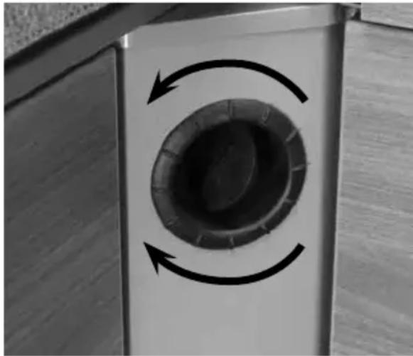
natural_image
Close-up of a circular mechanical component with rotational arrows indicating rotation, mounted on a metal frame (no text or symbols visible)Blown air
The air ducting outlets on some models are of the butterfly type, and if fitted these may be opened or closed by adjusting the butterfly valves. Twisting the disc in its housing directs the flow in the direction required. One outlet on each leg of the air ducting layout must be kept open at all times, and when high specification (Combi 6) heating systems are fitted, depending on the number of blown air outlets in the layout, butterfly fittings may not be present.
Under no circumstances should the air ducting outlets be blocked.
Note: The next instructions detail the operation of the Combi Control Panel - for further details of the Truma Combi appliance, please see the following section.
Truma Heating System Control Panel
Truma CP Plus Digital Timer Control
The Truma CP-Plus controller is fitted to control the operation of the Truma Combi appliance.
Safety instructions
- The device may only be operated if it is in perfect working order.
- Arrange for malfunctions to be rectified immediately. Only rectify malfunctions yourself, if the remedy is outlined in the troubleshooting information in these Operating Instructions.
- Do not repair or modify the device!
- Only allow the manufacturer or its customer service to repair a faulty device.
Note: If the power supply to the systems is interrupted for longer than 20 minutes, the time and date need to be entered again.
Important note
If the power supply to the systems is interrupted for longer than 20 minutes, the time and date need to be entered again.
Intended use
The control panel Truma CP plus serves to control and monitor a Combi heater and / or a Truma air conditioning unit. The device is designed for installation in caravans and motor-caravans.
For clarity only the instructions relevant to combi heating are included in this guide. Instructions relevant to air conditioning should be requested if an appropriate air conditioner is fitted.
TRUMA CP PLUS DIGITAL TIMER CONTROL
Display and control elements
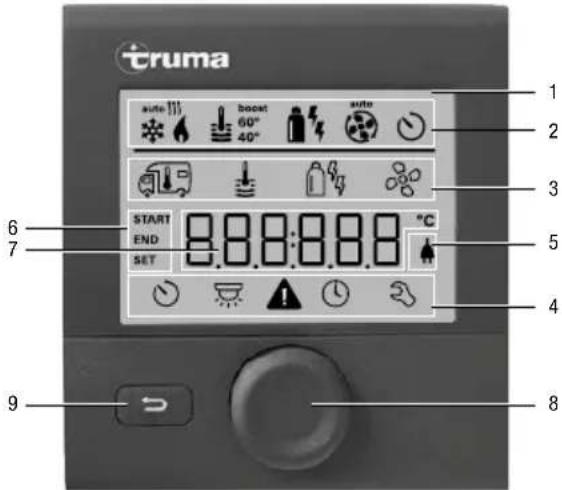
1 - Display
2 - Status line
3 - Menu line (above)
4 - Menu line (below)
5 - Display of mains voltage 230 V (shore power)
6 - Display timer
7 - Settings / values
8 - Control knob / push button
9 - Back button
The control knob / push button (8) is used to select menus in the lines (3 + 4) and configure the settings. These are shown via a display (1) with a lighted background. Pressing the Back button (9) takes the user back out of the menu again.
Control knob / push button
The control knob / push button (8) is used to select and change set values and parameters; these can be saved by clicking the control knob / push button. Selected menu items will flash.
natural_image
Simple diagram of a speaker icon with curved arrows indicating sound waves, no text or symbols presentTurn to the right (+)
- Menu is paged from left to right.
- Increase values.
Turn to the left (-)
- Menu is paged from right to left.
- Reduce values.

Clicking
- Accept (save) a selected value.
- Select a menu item, change to the setting level.
Press (3 seconds)
- Main switch function ON / OFF
Back button
Pressing the Back button (9) takes the user back out of the menu again and discards the settings. This means that the previous values are retained.
Functions
The functions in the menu lines (3, 4) of the control panel can be selected in any sequence. The operating parameters are shown in the status line (2) or the displays (5, 6).
Start / stand-by screen
After connecting the control panel to the power supply, a start screen is shown after a few seconds.
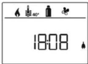
If no entry is made within a few minutes, the standby screen is automatically shown again. The display shows the time and current room temperature alternately.
Switch on / return to setting level
- Press the control knob / push button for longer than 3 seconds or the
- Back button.
The display shows the setting level. The first symbol flashes.
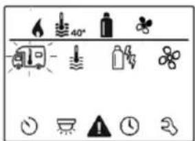
Note: Previously set values / operating parameters become active again after the system is switched on.
Switch off
- Press the control knob / push button for longer than 3 seconds.
Change the room temperature
- Use the control knob / push button to select the symbol in menu line (3).
- Click to change to the setting level.
- Depending on the connected device, use the control knob / push button to select between the heater or air conditioning unit.
- Use the control knob / push button to select the required temperature.
- Click the control knob / push button to confirm the value.
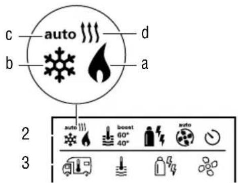
Heater
Settable temperature range 5 - 30 °C (1 °C steps)
a = heater * - Heater is switched on.
Air conditioning unit (not normally fitted)
Settable temperature range 16 - 31 °C (1 °C steps)
$$ b = \text { cool } ^ {*} $$
(Air conditioning unit is switched on)
$$ c = a u t o $$
(Air conditioning unit is set to automatic)
$$ d = h o t $$
(Air conditioning unit is in heating mod.)
* This symbol will flash until the required room temperature is reached.
Change the warm water level
- Use the control knob / push button to select the symbol in menu line (3).
- Click to change to the setting level.
- Use the control knob / push button to select the required level.
- Click the control knob / push button to confirm the value.
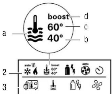
$$ \mathbf {a} = \text { Boiler } ^ {*} $$
(Warm water boiler is switched on)
$$ \mathbf {b} = 4 0 ^ {\circ} $$
(Warm water temperature 40 °C)
$$ \mathbf {c} = 6 0 ^ {\circ} $$
(Warm water temperature 60 °C)
TRUMA CP PLUS DIGITAL TIMER CONTROL
d = boost \*
(Targeted, fast heating of the content of the boiler [boiler priority]). The water temperature is kept at the higher level [around 62 °C] – Not Combi Diesel. Once the water temperature is reached, the room is heated again.)
* This symbol will flash until the required water temperature is reached.
Select power type
- Use the control knob / push button to select the symbol in menu line (3).
- Click to change to the setting level.
- Use the control knob / push button to select the required power type.
- Click the control knob / push button to confirm the value.
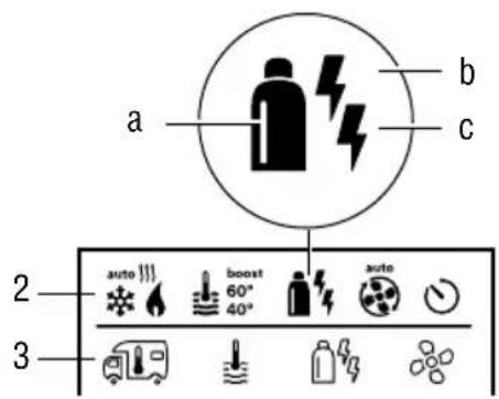
| Symbol | Operating mode | Power type |
| a Gas | Gas | |
| b EL 1 | Electro | |
| b + c EL | 2 Electro | |
| a + b Mix | 1* Gas + Electro | |
| a + b + c | Mix 2* Gas + Electro |
* Mixed mode
Special aspects in the mixed mode
Interruption of the power supply 230 V
Combi Gas
The heater automatically switches to the gas mode. As soon as the 230 V power supply is reconnected, the heater automatically switches
back to the mixed mode.
Malfunction in the combustion process (e.g. lack of fuel)
Combi Gas
The heater automatically switches to the electro mode. If the heater should operate in the mixed mode again, the cause of the malfunction needs to be rectified. Switch the heater off and on again on the control panel.
Select fan level
When the heater / air conditioning unit is connected.
- Use the control knob / push button to select the symbol in menu line (3).
- Click to change to the setting level.
- Use the control knob / push button to select the required fan level.
- Click the control knob / push button to confirm the value.
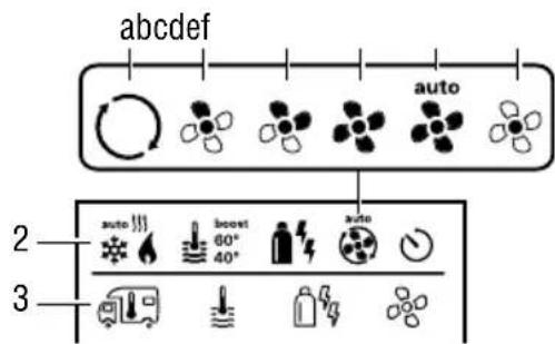
| Symbol | Operating mode Description |
| - Off | Fan is switched off |
| a Vent | |
| b Eco | Low fan level |
| c Mid | High fan level (only Combi Gas) |
| d High |
Set timer
- Use the control knob / push button to select the symbol in menu line (4).
- Click to change to the setting level.
Note: If the timer is activated (ON), the timer in the menu is shown as deactivated (OFF).
Enter start time
- Use the control knob / push button to set the hours, then the minutes.
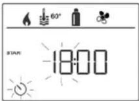
Enter end time point
- Use the control knob / push button to set the hours, then the minutes.
Note: If the start / end times are exceeded when entered, the operating parameters are only taken into consideration when the next start / end times are reached. Until then, the operating parameters set outside the timer remain valid.
Set the room temperature
- Click to change to the setting level.
- Use the control knob / push button to select the required room temperature.
- Click the control knob / push button to confirm the value.
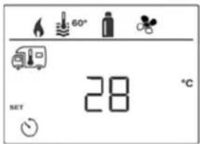
Set the warm water level
- Click to change to the setting level.
- Use the control knob / push button to select the required warm water level.
- Click the control knob / push button to confirm the value.
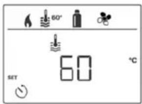
TRUMA CP PLUS DIGITAL TIMER CONTROL
Select power type
- Click to change to the setting level.
- Use the control knob / push button to select the power type.
- Click the control knob / push button to confirm the value.
Select fan level
- Click to change to the setting level.
- Use the control knob / push button to select the required fan level.
- Click the control knob / push button to confirm the value.
Activate the timer (ON)
- Click to change to the setting level.
- Use the control knob / push button to activate the timer (ON)
- Click the control knob / push button to confirm the value.
Note: The timer remains active, even for several days, until it is deactivated (OFF).
Deactivate the timer (OFF)
- Click to change to the setting level.
- Use the control knob / push button to deactivate the timer (OFF)
- Click the control knob / push button to confirm the value.
Switch lighting on/off
Available if an air conditioning unit is connected
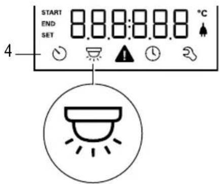
Set time
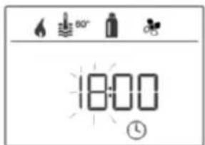
• The hour display flashes.
- Use the control knob / push button to set the hours (24 h mode).
- After clicking the control knob / push button again, the minute display will flash.
- Use the control knob / push button to set the minutes.
- Click the control knob / push button to confirm the value.
Service menu
Query the index status of a connected device
Change the background lighting of the control panel
There are 5 background lighting levels to choose from.
Change language
Select the required language from those available (e.g. English, German, French, Italian).
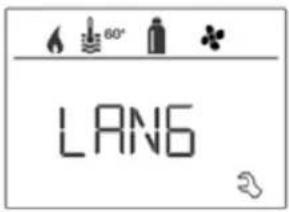
Display mains voltage 230 V
The symbol indicates that 230 V mains voltage (shore power) is available.
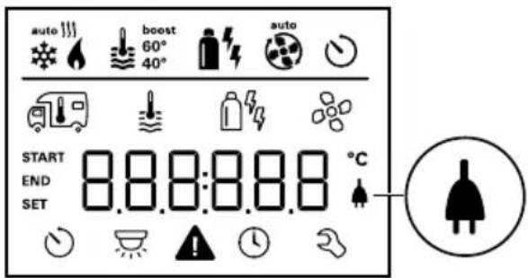
Warning
In the event of a warning, a warning symbol appears to indicate that an operating parameter has reached an undefined status. In this case, the affected device continues to run. As soon as the operating parameter returns to the set range, this symbol will turn off automatically.
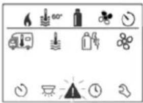
Read out the warning code
- Use the control knob / push button to select the symbol.
- Click the control knob / push button. The current warning code is shown. The cause of the warning can be identified and rectified via the error list.
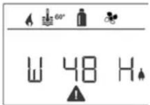
Cause rectified / return to setting level
- Click the control knob / push button.
Cause not rectified / return to setting level
- Press the Back button
Note: In this case, the warning is not acknowledged on the control panel and the warning symbol remains. The control panel remains in the warning status. Devices connected to the control panel can be operated.
TRUMA CP PLUS DIGITAL TIMER CONTROL
Malfunctions
In the case of a malfunction, the control panel immediately jumps to the menu level "malfunction" and shows the error code of the malfunction:
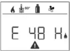
Cause remedied / return to setting level
- Click the control knob / push button.
- The respective device is restarted.
If the cause is not remedied, the malfunction will occur again and the control panel will jump again to the menu level "malfunction".
Cause not remedied / return to setting level
- Press the Back button.
Note: In this case, the malfunction is not acknowledged in the control panel and the warning symbol remains on. The device remains in the malfunction status. Other devices connected to the control panel can be operated.
Maintenance
This device is maintenance-free. Use a non-abrasive damp cloth to clean the front. If this proves inadequate, use a neutral detergent.
Disposal
The device must be disposed of in compliance with the administrative provisions of the respective country in which it is used. The national regulations and laws (in Germany these are e.g. the End-of-Life Vehicle Regulations) must be observed.
Troubleshooting instructions (Combi Gas heater)
If these steps do not rectify the malfunction, please contact the Truma Service.
| Error code Cause Remedy | ||
| #17 • Summer | mode with empty water containerWarm air outlet blockedCirculated air intake blocked | Switch device off and allow to cool.Fill boiler with waterCheck each of the outlet openingsRemove the blockage from the circulated air intake |
| #18 • Gas pressure regulator frozenToo much butane in the gas cylinder | Use the regulator heating (EisEx)Use propane (Butane is unsuitable for heating, especially at temperatures below 10°C | |
| #21 • Room | temperature sensor or cable faulty | Please contact the Truma Service |
| #24 • Potential under-voltage battery voltage too low <10.4V | Charge battery | |
| #29 • Heating | element for FrostControl has a short circuit | Disconnect the heating element plug on the electronic control unit.Replace heating element |
| #41 • Electronics are blocked • Please contact the Truma Service | ||
| #42 • Window | above the cowl is open (window switch) | Close the window |
| #43 • Over-voltage > 16.4V • Check the battery voltage and voltage sources eg. the charger | ||
| #44 • Under-voltage battery voltage too low < 10.0V | Charge battery. Replace any old batteries | |
| #45 • No 230V | operating voltageFaulty 230V fuseOverheating protection has triggered | Reconnect the operating voltage 230VReplace the 230V fuseReset the overheating protection.Allow the heating to cool down, remove the connection cover and press the reset button |
| #112 • Gas cylinder or quick-acting valve in the gas line closed | Check the gas supply and open the valves | |
| #212 • Combustion air intake or exhaust outlet closed | Check the openings for soiling (snow, ice, leaves etc) and remove | |
| #255 • No connection between the heater and the control panelControl panel cable faulty | Please contact the Truma Service | |
Truma Combination Heating System Function Description
The liquid gas heater Combi E is a warm-air heater with integrated hot water boiler (10 litre volume). The burner operates fan-supported, which ensures trouble-free function even when on the move. The unit also has heating elements for electrical operation.
In winter operation the heater can be used to heat the room and simultaneously warm water.
3 different options are available for operating the unit.
- gas operation only Propane / Butane for autonomous use
- electrical operation only 230 V for stationary use on camp sites
- or gas and electrical operation - mixed operation only possible in winter mode.
Winter operation (Space heating with water heating)
In winter operation, the unit automatically selects the required power setting according to the temperature difference between the temperature set on the control panel and the current room temperature. When the boiler is filled, the water is automatically heated as well. The water temperature depends on the selected operational mode and the heater output. All 3 energy selection options can be used for winter deployment.
With gas operation the unit automatically selects the output level that is required. Depending on the fuse protection at the camping site, power of 900 W (3.9 A) or 1800 W (7.8 A) can be manually selected for electrical operation.
If more output is required (e.g. heating up or low outside temperatures) gas or mixed operation should be selected so that enough heating power is always available. With mixed operation, 230 V electrical operation is preferred if the power requirement is low (e.g. for maintaining the room temperature). The gas burner is not enabled until the power requirement is higher, and is the first to switch off during heat-up operations.
Summer operation (Water heating only)
Gas operation or 230 V electrical operation is used for hot water preparation. The water temperature can be set to 40 °C or 60 °C. With gas operation the water is heated at the lowest burner setting. Once the water temperature is reached, the burner switches off. Depending on the fuse protection at the camping site, power of 900 W (3.9 A) or 1800 W (7.8 A) can be manually selected for electrical operation. Mixed operation is not possible. With this setting the unit automatically selects electrical operation. The gas burner is not enabled.
Repairs may only be carried out by an expert
Guarantee claims, warranty claims and acceptance of liability will be ruled out in the event of the following:
- modifications to the unit (including accessories),
- modifications to the exhaust duct and the cowl,
– failure to use original Truma parts as replacement parts and accessories,
– failure to follow the installation and operating instructions.
It also becomes illegal to use the appliance, and in some countries this even makes it illegal to use the vehicle.
During the initial operation of a brand new appliance (or after it has not been used for some time), a slight amount of fumes and smell may be noticed for a short while. It is a good idea to heat the device up several times in summer operation (60 °C) and to make sure that the area is well ventilated. Heat-sensitive objects such as spray cans or flammable liquids may not be stored in the same compartment where the heater is installed because, under certain conditions, this area may be subject to elevated temperatures.
Important operating notes
The integrity and tight fit of the exhaust gas double duct must be checked regularly, particularly at the end of long trips. Also check
the mounting of the appliance and the cowl. Following a blow-back (misfire) always have the exhaust gas system checked by an expert! Always keep the cowl for the exhaust duct and combustion air intake free of contamination (slush, ice, leaves etc.). A number of hot air outlets and the recirculated air intake openings must be free so that the unit does not overheat. The integrated temperature limiter blocks the gas supply when the unit becomes too hot.
Operating Instructions
Always observe the operating instructions and "Important operating notes" prior to starting! The vehicle owner is responsible for the correct operation of the appliance. Before using for the first time, it is essential to flush the entire water supply system through with clean water. If the heater is not being used, always drain the water contents if there is a risk of frost. There shall be no claims under guarantee for damage caused by frost!
Room thermostat
To measure the room temperature, a room temperature sensor is fitted to the furniture. The exact location is determined by the layout of the vehicle.
Taking into operation
Heating is possible without restrictions with gas, electrical and mixed operation, with or without water. Check to make sure the cowl is unobstructed. Be sure to remove any covers that may be present.
For operating on gas turn on gas cylinder and open the shut off valve at the manifold. For operating on electric operate the water heater switch on the power supply unit. See page 81.
Filling the water heater
Switch on power for water pump (main or pump switch) to prime the water system. Open hot water taps in kitchen and bathroom, (set preselecting mixing taps or single-lever fittings to "hot"). Leave the fittings open for as long as it takes for the boiler to displace the air and fill up, and the water to flow without interruption.
If just the cold water system is being operated, without using the water heater, the heater tank also fills up with water. To avoid frost damage, the boiler must be drained through the drain valve, even if the boiler was not operated.
When connecting to a central water supply (rural or city mains), a pressure reduction valve must always be installed to prevent pressures above 2.8 bar from developing in the water heater.
Draining the water heater
Switch off power to water pump (main or pump switch). Open hot water taps in kitchen and bathroom. In order to check the water that is flowing out, place an appropriate container (capacity 10 litres) beneath the drain valve.
Open the drain valve which is situated next to the boiler by lifting the yellow handle into the vertical position.
Check whether all of the water in the boiler (10 litres) has been drained into the container via the drain valve.
There shall be no claims under guarantee for damage caused by frost!
Maintenance
Only original Truma parts may be used for maintenance and repair work! Materials in the device which come into contact with water are suitable for use with drinking water (see manufacturer's declaration: www.truma.com / downloads / manufacturer's declaration).
Bio-film, deposits and limescale must be removed using chemicals to protect the unit from infestation by microorganisms. Only chloride-free products must be used in order to prevent damage to the unit. The effectiveness of the use of chemicals to combat microorganisms in the unit can be increased by heating the water in the boiler to
70 °C at regular intervals. The unit must stay switched on for at least 30 minutes and no warm water may be removed. The residual heat in the heat exchanger will heat the water up to 70 °C.
TRUMA COMBI BOILER
Fuses 12 V
The fuse is in the electronics beneath the connection cover. Replace the unit's fuse only with an identical fuse.
Device fuse: 10 A – slow – (T 10 A)
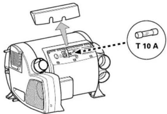
Fuses 230 V
The fuse and the power supply lines must only be replaced by an expert! The unit must be disconnected from the mains (all poles) before opening the electronic housing lid.
The fuse is in the power electronics (16) beneath the electronic housing lid.
This fine fuse must always be replaced with a fuse of the same type: 10 A, slow, interrupting capacity "H".
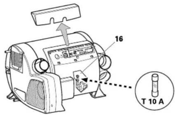
Overheating protection 230 V
The 230 V heating facility has a mechanical overheating switch. If the 12 V power supply is interrupted during operation or during the after-run period, for example, the temperatures within the unit could activate the overheating protection. To reset the overheating protection, allow heater to cool, remove connection cover and press red reset button.
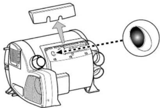
Technical data
determined in accordance with EN 624 or Truma test conditions
Device category
I_3 B/P in accordance with EN 437
Type of gas
Liquid gas (propane/butane)
Operating pressure
30mbar (see type plate)
Water contents
10 litres
Heating up time from approx 15°C to 60°C
Boiler approx 20 minutes (measure according to EN15033)
Heater + boiler approx 80 min
Water pressure
max 2.8 bar
Rated thermal output
(automatic output levels)
Gas operation
Combi 4 E: 2000 W / 4000 W
Combi 6 E: 2000 W / 4000 W / 6000W
Electrical operation
Combi 4 E / Combi 6 E: 900 W / 1800 W
Mixed operation (gas and electrical)
Combi 4 E: max. 3800 W
Combi 6 E: max. 5800 W
Gas consumption
Combi 4 E: 160-320 g/h
Combi 6 E: 160-480 g/h
Readiness-heat power requirement Combi 4 E
/ Combi 6 E:
Gas operation 5.2 g/h
Air delivery volume
(free-blowing without hot-air pipe)
Combi 4 E:
with 3 hot-air outlets max. 249 m3/h
with 4 hot-air outlets max. 287 m3/h
Combi 6 E:
with 4 hot-air outlets max. 287 m3/h
Current input at 12 V
Heater + boiler
Combi 4 E: Short-term max. 5.6 A
(average power consumption 1.1 A)
Combi 6 E: Short-term max. 5.6 A
(average power consumption 1.3 A)
Heating up of boiler: 0.4 A
Stand-by: 0.001 A
Heating element FrostControl (optional):
maximum 0.4 A
ALDE HEATING OPERATING INSTRUCTIONS
Alde Compact 3020
⚠ WARNING: Alde can accept no liability whatsoever for damage or injury resulting from failure to observe these instructions.
Specific Use
These instructions are approved for the Alde 3020 Compact HE boiler fitted in caravans, motorhomes or buildings in accordance with CE 0402 no. SC0653-13, and have the E5 mark for installation in vehicles in accordance with ECE R122, no. 00 001 and R10, no. 04 166, for use in central heating and hot water systems.
The boiler is not intended for use by persons (including children) with reduced physical, sensory or mental capabilities, or lack of experience and/or knowledge, unless they have been given instruction or are supervised.
The term “specified use” also covers observance of the operating and installation instructions.
The Alde 3020 Compact HE boiler must be installed or repaired by a competent person in accordance with current local regulations.
In the unlikely event that your boiler develops a fault, switch off the boiler and contact Alde, or your dealer or installer.
Operating and installation instructions for the Alde control panel are supplied separately.
The owner is always responsible for maintenance and arranging inspection.
Boiler Design
The boiler's internal heat exchanger consists of three concentric cylinders; the combustion chamber, the central heating cylinder and the hot water cylinder.
The combustion chamber is made from aluminium, and is divided into two halves by a baffle plate, with the burner head located in the top half, and the flue gases venting through the bottom half.
The combustion assembly is fixed to the end of the internal heat exchanger. It consists of the burner, combustion fan, gas valve, air
intake and exhaust ducts, and gas line.
Two electric heating elements are sealed inside the central heating cylinder, one for 1 kW, one for 2 kW.
Gas Heating
When gas heating is set to on, the combustion fan starts to revolve. Once the correct speed is achieved (in rpm), a signal is sent to the PCB for the burner to be lit. The gas valve opens, passing gas, and the ignition module on the PCB generates sparks at the electrode on the burner head.
When the burner ignites, a flame supervision device signals the ignition module to cease sparking. The burner fires until the boiler or room thermostat reach the setpoint.
Should the burner flame out unexpectedly, the FSD detects this and attempts to reignite (for about 10 seconds), before shutting down and raising a fault code.
Note: Listen carefully to the ignition sequence of the boiler. You should hear the whirl of the combustion fan, the clunk of the gas valve and the tick-tick of the ignition module.
Electric Heating
When electric heating is set to 1, 2 or 3 kW, relays on the PCB trip, feeding the 230v supply to the electric heating elements. These are controlled by the same programme as the gas heating.
Domestic Hot Water
The combi-type boiler automatically produces hot water. Heat is emitted from the central heating cylinder into the hot water cylinder. If the hot water cylinder is empty, the air is heated but no damage can result.
Note: In a good summer, for example, lower the desired temperature on the control panel to around 10 °C . The central heating will not circulate (unless the temperature drops to 10 °C ), but you will still have hot water.
⚠ WARNING:
- The boiler must not be switched on if there is no heat transfer fluid (HTF) in the system.
- Always drain down the freshwater system if there is risk of frost; in winter, for example. You may continue to use the boiler with no freshwater in the system, as required; no damage can result
- Always replace the HTF in accordance with the antifreeze product's lifespan. . If in any doubt, replace the HTF after 2 years.
- Only sterilise the freshwater system with a product suitable for stainless steel.
- Do not place stowage in the boiler compartment.
- Do not position awnings, tents or other enclosures around the flue terminal.
- Do not obstruct the flue. Be careful not to flood the flue when washing the vehicle.
- The gas heating must not be used when refuelling the vehicle at the service station or related facility.
Domestic Hot Water
Being a combi-type boiler, the Alde 3020 Compact HE has an integrated, stainless steel hot water cylinder that holds approximately 8.4 litres of freshwater.
The boiler can produce around 12 litres of 40^ C warm water per 30 mins (at a cold water temperature of 10^ C). If only the electric heating is used, this capacity is slightly reduced.
The hot water should not be used for drinking or cooking.
Always flush out the hot water cylinder before use, especially when it has stood empty for some time.
Note: Any steriliser products should be suitable for use with stainless steel.
Avoid steriliser products containing sodium hyperchlorite, for example, as these will cause severe corrosion damage to the hot water cylinder. Read the product label or contact the product manufacturer for details.
When the hot water cylinder is in continuous use, it should be drained and refilled once a month. This recreates the air cushion in the hot water cylinder that absorbs pressure surges.
Note: If continuously using the hot water cylinder in a hard water area, fit an inline scale inhibitor to minimise the effects of limescale
Target hot water temperature is greater than 50^ C in normal operation, to prevent the growth of Legionella. Over 50^ C, the hot water will be heated to the maximum achievable temperature at the time. This allows the hot water to achieve disinfection temperatures, and increases warm water performance.
If scalding hot water temperatures are a concern – such as with the young, elderly or infirm – thermostatic mixing valves (TMVs) can be fitted, and may be required by local regulations.
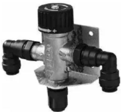
natural_image
Close-up of a metallic pressure regulator valve with black and black fittings (no visible text or symbols)⚠ WARNING: Always drain down and completely empty the hot water cylinder when there is risk of frost, unless the vehicle is explicitly stated to be self-winterising by the vehicle manufacturer.
Failure to drain the hot water cylinder when there is a risk of frost may result in frost damage, and is not covered under warranty.
ALDE HEATING OPERATING INSTRUCTIONS
Draining Freshwater
- Switch off the water pump.
- Open all water taps, showers, etc.
- Open the safety/drain valve by lifting the yellow tab (Fig 1 [M]), or by turning the blue knob (Fig 1 [K]) 90°.
- The system will drain directly below the vehicle through the clear plastic hose on the safety/drain valve. Check that all water has emptied out (7–10 litres). Leave the valve in the open position until the next time the hot water cylinder is used.
Note: Check that the red breather valve (Fig 1[N]) is allowing air to enter the hot water cylinder, when it is being drained, and that the clear plastic hose is not obstructed.
Figure 1
Open the manual safety/drain valve
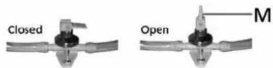
Opening the safety/drain valve
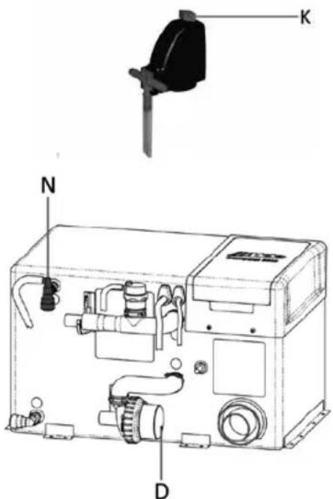
Heat Transfer Fluid
The central heating system is filled with heat transfer fluid (HTF), a solution of 50% ethylene glycol antifreeze and 50% water.
⚠ WARNING: The boiler must not be switched on if there is no HTF in the system.
The antifreeze manufacturer will have a maximum water hardness recommendation. Read the product label or contact the product manufacturer for details.
Note: For re-filling Alde recommends antifreeze meeting VAG G12++ or G13 specification, and deionised water (0 ppm).
50:50 ethylene glycol antifreeze and water will protect against frost down to -35–37 °C. A refractometer and/or hydrometer can be used to measure the strength of the antifreeze solution.
Corrosion protection will vary depending on the lifespan of the antifreeze. Read the product label or contact the product manufacturer for details.
⚠ WARNING: Always replace the HTF in accordance with the antifreeze product's lifespan. If in any doubt, replace the HTF after 2 years.
The corrosion inhibitors found in ethylene glycol antifreeze may not be cross-compatible. When topping up or replacing the HTF, ensure the new antifreeze is compatible with the current antifreeze product. Read the product label or contact the product manufacturer for details.
Note: As a rough guideline, blue and red antifreeze products are not compatible with each other, but VAG G12++ and G13 spec antifreeze (purple/magenta) is compatible with both.
Failure to fill with suitable HTF may result in severe damage to your Alde system, and is not covered under warranty.
Filling
The central heating system is filled with HTF through the expansion tank, either by hand, or using the Alde service pump. Any containers used for handling or storing the HTF should be checked first, and must be visibly clean to avoid introducing contaminants or foreign objects into the system.
Alde recommends using the Alde 1900-811 or 839 twin-motor service pump to fill the system.
To fill the system by hand, unscrew the expansion tank cap (Fig 2 [R]), and lift the circulation pump (Fig 2 [S]) out of the tank (if applicable). Carefully pour the HTF into the tank, and repeat until the fluid level is about 1 cm above the MIN mark when cold.
Figure 2
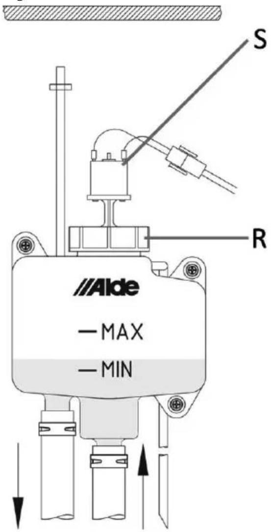
Central Heating
The boiler is set to an upper limit temperature of 85^ C, i.e., the temperature of the heat transfer fluid (HTF) as it circulates around the pipes, radiators, convectors, et al.
To ensure the best performance from hydronic heating, air must be able to circulate freely around the back of the furniture (Fig 3). Air vents, cut into the top and bottom of the furniture must be unobstructed by carpets, cushions, or stowage, etc.
The full length of a convector should be ventilated for best performance.
Note: Use gas and electric heating simultaneously for the best performance. The boiler will only use as much energy as is needed, and is 93% efficient on a SEBDUK based test.
Figure 3
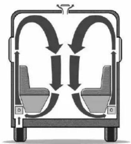
flowchart
graph TD
    A["Left Seat"] --> B["Right Seat"]
    B --> C{Bidirectional Flow}
    C -->|Upward Arrows| D["Left Seat"]
    C -->|Downward Arrows| E["Right Seat"]
    D --> F["Left Seat"]
    E --> G["Right Seat"]
    style A fill:#f9f,stroke:#333
    style B fill:#f9f,stroke:#333
    style C fill:#ccf,stroke:#333
    style D fill:#cfc,stroke:#333
    style E fill:#cfc,stroke:#333
ALDE HEATING OPERATING INSTRUCTIONS
Bleeding Air
The HTF will contain some air. This is unavoidable. Air bubbles can also be introduced when the system is filled.
In a newly-filled central heating system, you will need to bleed air from the bleed points to ensure best performance. There is an automatic air bleed valve on the boiler. There is also an air vent on the expansion tank.
The installer should fit bleed points elsewhere in the system, especially where the pipes step up and down, and on radiators and towel rails. Air will accumulate at these high points and become trapped.
Note: Contact the dealer or installer for details on where the bleed points are in your system, and how to access them.
To bleed the system, set the desired temperature to 30^ C and select gas heating on the control panel.
If fitted set the 12V inline circulation pump on the side of the boiler to speed 5 (Fig 1 [D]), by turning the blue speed dial clockwise, on the face of the pump motor. NB: Speed is not adjustable if using the 12V circulation pump fitted in the expansion tank.
After 10 mins, set the pump back to its normal running speed (2 for a caravan, 3 for a motorhome).
Now power off the Alde 3020 Compact HE boiler completely, making sure that the circulation pump is not active.
Follow the flow pipe from the boiler, and bleed the system at each bleed point.
If Alde bleed points have been fitted, these are metal bleed screws mounted on black EPDM rubber connectors (Fig 4). Have a cloth in hand. To open, turn the screw anticlockwise between thumb and forefinger. Air will hiss out. When fluid trickles out, close the bleed screw and mop up fluid with the cloth.
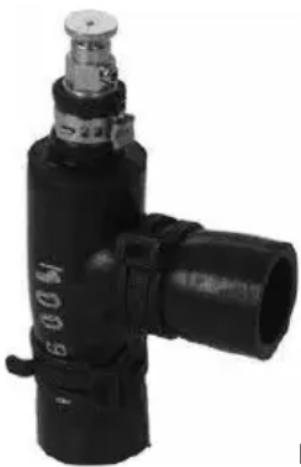
natural_image
Close-up of a black industrial pressure regulator with no visible text or symbols on the body (pure branding)Fig 4
Move on to the next bleed point and repeat, until all bleed points have been tended to.
Air Lock
If enough trapped air accumulates at one point, an air lock can result and prevent the circulation of hydronic heating.
A ramp or steep slope can be used to raise one end of the vehicle, causing the trapped air to shift around the system. Repeat the full bleed procedure. A caravan can be slowly and carefully tilted to reproduce this effect.
To clear a stubborn air lock in under 15 minutes, an Alde-certified service agent can use the Alde 1900-811 or 839 twin-motor service pump.
230v ELECTRIC
The Alde 3020 Compact HE boiler has two 230 V electric heating elements, outputting 1050 W and 2100 W, or 3150 W combined, and drawing 5 A, 9 A, and 14 A respectively (rounded).
230v breakers, fuses, fused spurs and isolator switches should be rated for 16 A.
Before using electric heating, check the current limit on the electric supply you are hooking up to.
- 6 A limit, only use 1 kW electric heating.
- 10 A limit, use 1–2 kW electric heating.
- 16 A limit, use 1–3 kW electric heating.
Note: If the electric supply has unstable voltage, the amperage will also fluctuate.
LPG
LPG (liquefied petroleum gas) has two main variants, propane and butane gas. The gas heating in your Alde 3020 Compact boiler can use propane or butane gas as fuel. Many LPG fuels contain a mixture of propane, butane and other additives.
BS 5482 Part 1 states, “For butane cylinders, satisfactory service might not be obtained at temperatures of less than 10^ C; the most suitable temperature range is from 13 to 30^ C. For temperatures less than 13^ C, the use of propane should be considered.”
For this reason, Alde recommends using propane gas for all year round gas heating.
LPG cylinders contain both gas and liquid forms. When the cylinder is filled, high pressure transforms the gas into liquid. The liquid reverts to gas when the valve on the cylinder is opened.
LPG is a flammable gas. It can be a fire and explosion hazard if stored or used incorrectly. Store cylinders vertically and securely, to prevent them from toppling.
Do not mount your LPG cylinder horizontally or use liquid phase gas cylinders. Liquid–gas explosion may result. Read the product label or contact product manufacturer for details.
LPG is heavier than air. Should a gas leak occur, floor vents in a caravan or motorhome should allow the gas to escape from the vehicle. For this reason, always ensure floor vents are unobstructed.

WARNING: The boiler compartment contains the gas connection, floor vents and flue hoses. Do not place stowage in the boiler compartment.
In the event of a gas leak, or if you smell gas:
- Extinguish all naked flames
- Open all doors and windows
- Close all gas valves, including the valve on the cylinder.
-
Do not smoke.
-
Do not operate any electrical appliances or switches.
- Arrange for immediate inspection of the gas system by a competent person in accordance with current local regulations.
LPG from the cylinder is reduced in pressure by a regulator, and is supplied to the boiler at low pressure (30 mbar). Never use an unregulated high pressure supply.
Where oil and dirt in the gas supply are a concern, gas filters should be fitted to prevent blockage of the boiler gas valve.
Note: Gas heating must not be used whilst driving your vehicle unless a safety shut-off device is fitted to the gas system. Current local regulations must be adhered to.
Flue
The burning of LPG produces CO^2 (carbon dioxide), a non-toxic, asphyxiant gas.
Exhaust flue gas can cause possible burns and poisoning. Avoid inhaling exhaust flue gas.

WARNING:
Do not position awnings, tents or other enclosures around the flue terminal.
Air supply is essential for clean combustion. The air intake is located in the flue terminal. For best performance, the flue terminal should be well vented. If leaving the gas heating unused for a period, ensure the flue terminal is covered to prevent pest animals nesting in the flue.

WARNING:
Do not obstruct the flue. Be careful not to flood the flue when washing the vehicle.

WARNING: Air is sucked into the mbustion chamber via the air intake.
The gas heating must not be used when refuelling the vehicle at the service station or related facility.
ALDE HEATING OPERATING INSTRUCTIONS
Maintenance
There is no manufacturer's service requirement for the Alde 3020 Compact boiler itself.
Current local regulations must be adhered to. The installation of the boiler should be inspected annually for gas safety.
LPG hoses should be regularly checked for signs of damage and should be replaced, at maximum, after 3 years of use.
Bleed air from the system when newly filled, when the vehicle has been standing unused for a period, and before departing on holiday.
The fluid level in the expansion tank should be about 1 cm above the MIN mark when cool. The heat transfer fluid (HTF) should be topped up if below this level, to prevent a break in circulation. Only top up with compatible HTF.
Note: Never leave the system empty of HTF.
⚠ WARNING: Always replace the HTF in accordance with the antifreeze product's lifespan. If in any doubt, replace the HTF after 2 years.
Failure to maintain the condition of HTF may result in frost and/or corrosion damage, and is not covered under warranty.
When the hot water cylinder is in continuous use, it should be drained and refilled once a month. This recreates the air cushion in the hot water cylinder that absorbs pressure surges.
Winter
When camping in the winter, always ensure the flue terminal remains unobstructed by snow and ice. Extensions for roof flue terminals, and condensate spouts for side flue terminals are available from Alde.
Check the strength of the heat transfer fluid (HTF) with a hydrometer and/or refractometer. It should measure 50% ethylene glycol antifreeze, or -35-37°C.
The central heating can still be used with no freshwater in the system. The air in the hot water cylinder is heated but no damage can result.
⚠ WARNING: Always drain down and completely empty the hot water cylinder when there is risk of frost, unless the vehicle is explicitly stated to be self-winterising by the vehicle manufacturer.
If camping in temperatures below -10^ , consider carrying spare parts in the event of an emergency. Alde recommends a 12v circulation pump for the expansion tank (with cabling), a PCB, and 4–5 litres of ready to use antifreeze. These spare parts should be kept well insulated and in the warmest part of the vehicle; for example, in the wardrobe, near to the expansion tank pipes.
If storing the vehicle for winter, ensure the flue terminal is covered to prevent pest animals nesting in the flue.
If using the light duty 12v circulation pump in the expansion tank, do not leave the central heating on over winter, even with a low desired temperature set.
Note: Air the vehicle over winter without wearing out the light duty pump. Use the programmable Alde control panel to automatically heat the vehicle for 24 hours, once a week.
Trouble-Shooting
The Alde control panel will display any error messages. See the Operating and Installation Instructions supplied separately.
The system is completely dead, the control panel is blank
- Check the 20 mm T3.15 Amp glass fuse in the boiler. This is located under the lid of the black plastic service hatch, in a green plastic fuse holder.
- Check the 12v supply to the boiler, it should be above 12v.
- Check the 12v cable is plugged into the boiler. Check the cable is plugged into the Alde control panel.
The boiler will not ignite on gas
- Check the gas cylinder is full. Try a different gas cylinder, ensuring it is propane gas.
- The system may not need to use gas heating, if also using electric heating.
- The fluids in the boiler may already be at operating temperature.
The boiler will not heat on 230 V electric
- Check that any 230v isolator switches are on (they will often have an LED indicator).
- Check the 230v supply to the vehicle.
- The fluids in the boiler may already be at operating temperature.
No hot water
- Check that hot water ignore is not activated on the Alde control panel.
- Check that constant pumping is not activated on the Alde control panel.
- Check for other conflicting settings on the Alde control panel.
- Check the freshwater supply and water pump.
No central heating
- Bleed the system of air.
- Check the fluid level in the expansion tank.
-
Check that the circulation pump is responding.
-
Check that hot water boost is not activated on the Alde control panel.
- Use gas and electric heating.
- Check that vents in the furniture are not obstructed.
- Check the condition of the heat transfer fluid.
- Most vehicles will reach a comfortable temperature within an hour, in non-extreme conditions.
If problems persist, please contact contact Alde, or your dealer or installer.
WARRANTY
Alde undertakes to rectify any manufacturing defect or early component failure through normal use that occurs within 12 months of the installation date.
If your Alde boiler develops a fault, your first action should be to contact your dealer or installer, as they will be familiar with your installation and vehicle, and how to make a claim under warranty.
Alde International (UK) Ltd Huxley Close Park Farm South Wellingborough Northamptonshire NN8 6AB
Tel. 01933 677764
www.alde.co.uk
ALDE HEATING OPERATING INSTRUCTIONS
Alde 3020 - 113
Colour Touch Operating Instruction
This quick start guide allows end users to confidently use the core features of their Alde control panel. See the operating and installation instructions for the Alde control panel for more details.
Important: Please read the operating instructions for the Alde 3020 Compact HE boiler before using the system.
1. Starting the system
i. Both the control panel and boiler are off.
natural_image
Front view of a computer monitor with two buttons labeled 'Power' and 'MENU' (no additional text or symbols)ii. To start the system, press the Power button on the control panel. The Splash Screen is displayed and green LED is lit. The boiler will now start with the previously saved settings (factory settings by default).
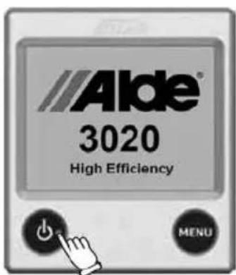
The system will now be drawing variable 0.2–1 A of current from the 12v supply.
2. Standby screen
The Standby Screen is displayed after the Splash Screen. This screen contains useful information about the status of your heating system.
Note: If Standby Screen is set to "Dark" in Backlight settings, the Standby Screen will not be displayed, the screen will be dark unless touched.
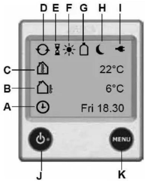
A. Clock
Clock is enabled. Day of the week and time shown.
B. Outdoor temperature
Optional outdoor temperature sensor required.
C. Room temperature
Measured at the control panel.
(Optional discrete room temperature sensors available).
D. Circulation pump
Central heating circulation pump is active.
E. Delayed start
Delayed Start/Cycle is enabled.
F. Day mode
Day Mode active.
G. Gas cylinder status
Gas Cylinder Status. Full/empty and active
EisEx shown. (Additional accessories required).
H. Night mode
Night Mode active.
I. 230v supply
If not displayed, the boiler is not receiving 230v supply.
J. Power button
Press to switch system on-off. Lit green LED indicates system is on.
J. Menu button
Press to access Main Menu from Standby Screen or Settings Menu.
3. Main menu
Press MENU button to access the Main Menu from the Standby Screen or Settings Menu. The screen will revert to the Standby Screen after 30 secs if untouched.
i. Standby Screen. Press MENU button.
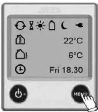
ii. Main Menu.
a. What's Activated Menu b. Settings Menu
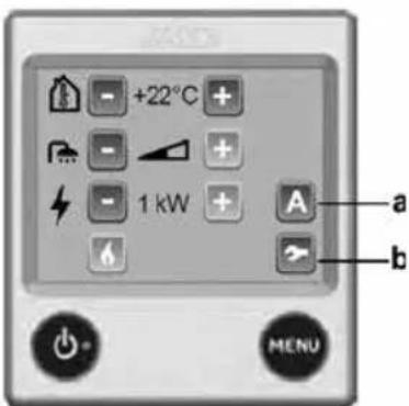
Desired Room Temperature
The desired room temperature can be set from 5 to 30°C, in 0.5 increments.
Tip! The World Health Organisation recommends a room temperature of 18–24°C for healthy living.
Note: If Day or Night Mode are active, the temperature cannot be adjusted, the Plus and Minus buttons will be greyed out.
-
The current desired room temperature is displayed.
-
Adjust by pressing Plus or Minus button.
Domestic Hot Water
The Alde boiler stores 8.4 Litres of hot water as standard. If the hot water cylinder is empty, the air is heated but no damage can result.
Tip! In a good summer, for example, lower the desired temperature on the control panel to around 10^ C. The central heating will not circulate (unless the temperature drops to 10^ C), but you can still control hot water.
Note: If Day or Night Mode Sans Hot Water are active, the hot water cannot be adjusted, the Plus and Minus buttons will be greyed out.
i. Hot Water Ignore. Volume bar empty. No attempt is made to heat hot water specifically. This saves energy when the freshwater is drained down.
ii. Hot Water Normal. Volume bar half-full. Hot water is heated to greater than 50°C. NB: If Circulation Pump is set to Continuous, this option will not be available.
iii. Hot Water Boost. Volume bar full. Central heating circulation is disabled for 30 mins. Hot water is heated to greater than 65°C. After 30 mins the system reverts to Hot Water Normal.
iv. Adjust by pressing Plus or Minus button.
ALDE HEATING OPERATING INSTRUCTIONS
Electric Heating
Check that 230v supply is displayed on the Standby Screen. The Alde boiler is programmed to use power economically and there are times when it may use no power at all, even if set to 3kW.
i. Select Off, 1, 2 or 3 kW electric heating. More power equals better performance, but may be restricted by the current (amps) limit on the electric hook-up.
ii. Adjust by pressing Plus or Minus button.
Max current draw from 230 V supply is 4.5 A on 1 kW, 9 A on 2 kW, 14 A on 3 kW. If the electric supply has unstable voltage, the amperage will also fluctuate.
Gas Heating
The Alde boiler is programmed to use power economically. The gas burner has two stages, shifting dynamically between low or full flame. There are times when it may use no power at all, even if gas heating is selected.
i. Press the Flame button to select gas heating. Green is on, blue is off.
Use both gas and electric heating for best performance.
4. Shutting down the system
To save energy, the control panel only updates the boiler after the last adjustment is made. Wait 10 secs before shutting down the system to ensure the boiler is updated.
Press the Power button again. The screen goes dark, the green LED is unlit. The system is off.
5. Setup
Most UK installations do not need setting up in the Settings Menu, and use default factory settings.
Restore default factory settings
Before using the system for the first time, restore default factory settings. Your control panel may have been tested by the dealer or installer, and some settings may have been
changed.
i. Press Tool button to access the Settings Menu (bottom right in Main Menu).
ii. Press down arrow, until Reset button is displayed.
iii. Press the Reset button to proceed

Setup expansion tank pump
To use the 12 V circulation pump in the expansion tank, you must set it up. This is not a default factory setting.
Note: Under factory settings, the system will use the 12 V inline circulation pump by default.
i. Press Tool button to access the Settings Menu (bottom right in Main Menu).
ii. Press down arrow, until Circulation Pump button is displayed.
iii. Press Circulation Pump button, select Expansion Tank Pump to proceed.

flowchart
graph LR
    A["Tool Icon"] --> B["Refresh Arrow"]
    B --> C["Circular Feedback Loop"]
Setup Antimicrobial function
To actively kill Legionella, setup the Antimicrobial function. At 2:00 every night, the hot water will be heated to over 65°C for 30 mins. This further reduces the risk of Legionella.
i. Press Tool button to access the Settings Menu (bottom right in Main Menu).
ii. Press down arrow, until Antimicrobial button is displayed.
iii. Press Antimicrobial button to proceed.

6. Maintenance
The Alde control panel requires no maintenance, other than cleaning of the screen as needed. Use a microfibre cloth to clean the touchscreen.
Note: Consider removing the Alde control panel over winter, if the vehicle is to be kept in storage and is susceptible to damp.
ALDE HEATING OPERATING INSTRUCTIONS
Trouble shooting
Any error messages will be displayed on the Standby Screen. Error messages can be cleared by switching off 12 V supply to the boiler for 10 secs.
The system is completely dead, the control panel is blank
- Check the 20 mm T3.15 Amp glass fuse in the boiler. This is located under the lid of the black plastic service hatch, in a green plastic fuse holder.
- Check the 12 V supply to the boiler, it should be above 12 V.
- Check the 12 V cable is plugged into the boiler. Check the cable is plugged into the Alde control panel.
"Panel failure 1" & "Panel failure 2"
- Moisture is trapped in the control panel.
- Remove the Alde control panel from the vehicle and air in a warm, dry place overnight.
"Gas failure"
- Out of gas or gas is not igniting.
- Check the gas cylinder is full. Try a different gas cylinder, ensuring it is propane gas.
"Overheat red fail" or "Overheat blue fail"
- Bleed the system of air.
- Check the fluid level in the expansion tank. It should be 1 cm above Min mark when cool.
- Check the circulation pump is responding.
- Wait 15 mins for the fluid to cool down.
"Overheat PCB"
- Failsafe in boiler has triggered.
- It should be 1 cm above the Min mark when cool.
- Check the boiler compartment is ventilated, and that the vents are unobstructed. Do not place stowage in the boiler compartment.
"Fan failure"
- Combustion fan speed too low. Bearing may be stiff after a period of disuse.
- Automatically clears after 5 mins. Please try again.
"Connection failure"
- Loose connection between Alde control panel and boiler.
- Unplug cable at the control panel and boiler, then carefully plug back in.
- Check there is slack on the cable at the control panel, but not excessive weight from free-hanging/unmanaged cable.
"Window open"
- Optional window sensor has triggered, gas heating is suspended. Automatically clears and gas heating resumes when window is closed.
"Connection fail ext"
- Break in comms between Alde control panel and daisy-chained third party control panel.
- Check the cable between the Alde control panel and third party control panel.
"Low battery"
- 12 V supply to boiler has dropped below 10.5 V, possibly causing system brownout.
- Automatically clears when 12 V supply reaches 11 V.
"No match Heater/Panel"
- Control panel is incompatible with boiler PCB.
- Check control panel part number. Control panel 3020-013 is for 3020 A-series boiler, 3020-113 is for 3020 HE-series boiler.
If problems persist, please contact Alde, or your dealer or installer.
For our frequently asked questions, or download all instruction manuals, please visit our web site at: www.alde.co.uk
Thetford refrigerator
Instructions for use
N3000-E series with LED control panel
model A
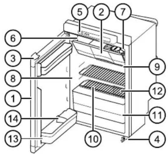
model B
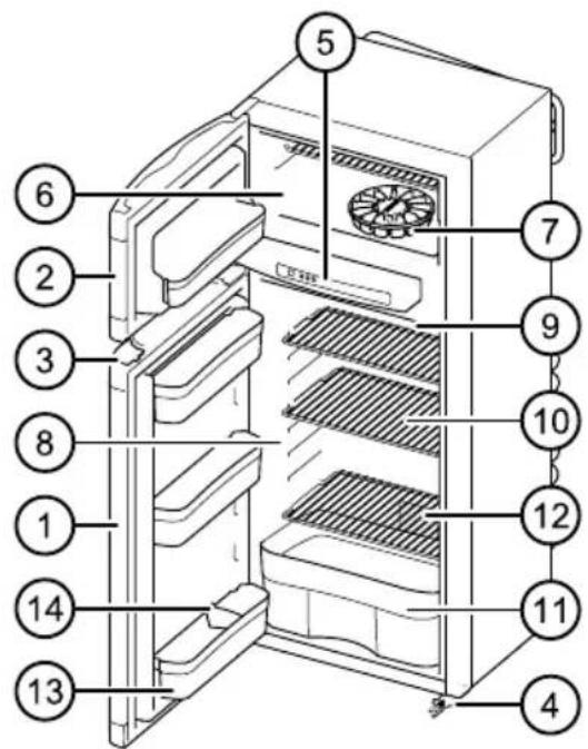
LED-control panel
(N3000-A series with touchscreen
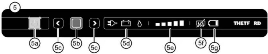
Main parts
- Refrigerator door
- Freezer door
- Door lock
- Security lock (dependent on model)
- Control panel LED
5a. On/off switch
5b. Confirmation button
5c. Arrow buttons
5d. Symbols sources
5e. Cooling level indicators
THETFORD REFRIGERATOR
5f. Symbol ‘anti-condensation (only for model B)
5g. Symbol 'batteries empty' (optional extra)
6. Freezer compartment
7. Ice cube tray
8. Refrigerator compartment
9. Cooling fins
10. Storage shelves
11. , Vegetable bin
12. Serial label
13. Door bins
14. Bottle retainer
Introduction
This Thetford refrigerator is specially developed for caravans or motorhomes. It meets high quality standards, is user friendly and gives you all the convenience during holidays and short trips.
Before operating and using this refrigerator we advise you to read the manual completely. Keep this manual in a safe place for future reference.
For the latest version of the manual please visit www.thetford-europe.com
Use safely
For correct and safe use of this refrigerator, you need to observe several precautions and general recommendations. If these instructions have not been followed, warranty claims will not be accepted.
⚠ WARNING: What to do if you smell gas. Directly close the valve of the gas bottle, extinguish any naked flames, do not switch on any electrical devices or lighting, open the windows and leave the room. Then contact the Customer Service Department in your country or holiday location.
⚠ WARNING: What to do if you smell a pungent odour from the cooling system. Switch off the refrigerator, extinguish any naked flames, provide sufficient ventilation through vents, windows and doors. Then contact the Customer Service Department in your country or holiday location.
Maintenance
- Make sure that installation, electrical connection, maintenance and periodical inspection of the gas system will be done by a qualified technical person, according to Thetford's instructions (www.thetford-europe.com) and local safety rules;
- Never open or damage the cooling system at the back of your refrigerator. The cooling system is pressurised and contains substances that are harmful to your health;
- Never attempt to repair parts of the gas system, the gas flue or electrical components yourself. The repairs may only be done by a qualified party. Please contact the Customer Service Department for further support and addresses;
- Before carrying out any kind of maintenance or cleaning, switch off your refrigerator;
- Never expose the refrigerator to rain.
Use of gas
- The refrigerator only runs on liquid gas (propane, butane or a mixture of these both). It does not run on natural gas or coal gas;
- Only use gas which is mentioned on the serial label inside the refrigerator;
- It is recommended to use an additional filter when operating on Liquefied Petroleum Gas (LPG);
- Make sure the type and position of the gas bottle meets the latest technical regulations;
- Change the gas bottle in open air and out of reach of any possible source of ignition;
-
Never obstruct the ventilation openings in the gas bottle storage location;
-
Keep flammable material away from the refrigerator;
- Do not use gas to power your refrigerator in the vicinity of petrol stations.
Food
- Respect the expiry date printed on the packaging of food;
- Defrosting, cleaning or maintenance of the refrigerator can shorten the preservability of food.
Switch on refrigerator
Note: To secure optimal performance, level your vehicle before operating the refrigerator.
Note: We advise to clean the inside of the refrigerator properly, before using the refrigerator.
To switch on the refrigerator, press the on/off switch and hold it for 1 second. A light in the on/off switch will turn green.
Note: After 10 seconds the settings will dim. The green light indicates the refrigerator is still in function.
To check the settings push the confirmation button. The last selected settings will light up.
For optimal performance, switch on the refrigerator 8 hours before placing food in it.
Selecting source
After switching on the refrigerator, push the confirmation button and hold it for two seconds. The symbols for the sources light up and start to blink.
Choose the desired source by pushing the arrow buttons.
Confirm your choice with the confirmation button.
Sources
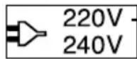
The refrigerator is powered by the mains.
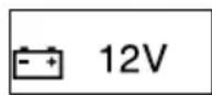
The refrigerator is powered by the battery of your vehicle.
The refrigerator is powered by the connection of a gas bottle.
Note: The refrigerator is only operated, when the control panel is powered. A stand alone model (installed by your dealer) is operational using AA batteries in the event of no mains or battery.
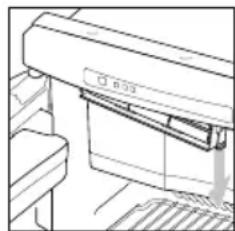
natural_image
Line drawing of a printer or printer with no visible text or symbolsTherefore open the small cover underneath the control panel, as illustrated. Place 6 new 1.5 V AA/LR6 batteries, according to the illustration in the cover.
Note: Always use the gas connection or mains voltage to start up and cool. Operating on 12 V is only effective while the engine of the vehicle is running.
Note: The performance of the refrigerator, by operating on 12 V, is dependant on the thickness and length of the wiring and the overall installation of the vehicle.
Note: When selecting gas, the flame should be ignited within 30 seconds. If the system fails, restart the refrigerator and select the gas source again.
Note: From about 1000m above sea level problems of a physical nature can occur when lighting the gas. This does not mean that the refrigerator is not working properly..
THETFORD REFRIGERATOR
Selecting cooling level
After switching on the refrigerator, push the confirmation button and hold it for two seconds.
The symbols for the sources start to blink. Push the confirmation button again.
The cooling level indicators start to blink. Use the arrow button to choose the desired cooling level.
Confirm your choice with the confirmation button.
Lowest cooling level ■ ■ ■ ■ ■ Highest cooling level
Your refrigerator meets the climate class SN requirements according to EN/IOS 7371 at a temperature of 10^ C to 32^ C.
Note: We advise to set the refrigerator on cooling level 3, with an ambient temperature between 15°C and 25°C. A higher temperature needs a higher cooling level, a lower temperature a lower level.
Note: To improve the cooling performance of your refrigerator in high temperatures, Thetford advises to install the Ventilator Kit. It helps to detract the warm air quicker to the vents. The Ventilator Kit is suitable for all Thetford refrigerators.
Control of optional extras
Batteries empty (present with the stand alone models, installed by your dealer)
When your refrigerator is provided with the stand-alone option, it will run 1.5 V AA / LR6 batteries for approximately 7 days in combination with gas supply. When the red symbol 'batteries empty' blinks, you have to replace batteries within 24 hours.
Remove all batteries out of the small cover underneath the control panel and replace 6 new batteries.
⚠ WARNING: Only use 1.5 V AA/LR6 batteries. Do not use rechargeable batteries for this function in the refrigerator.
Note: If you are not going to use this function for more than two weeks, remove all batteries.
Note: If you don't have enough batteries or want to use your refrigerator for a very short period it is possible to use only 3 batteries in a row. Your refrigerator will run for approximately half a week now.
Anti-condensation (present on model B)
To prevent the control panel from condensation, the anti-condensation function is automatically switched on. Only switch off this function when little energy is present.
Push both arrow buttons together at once and hold them for 2 seconds. The symbol ‘anti-condensation off’ will light up on the control. To switch on the function again, push both arrow buttons for 2 seconds once more.
Note: When your refrigerator runs on AA batteries, anti-condensation is switched off automatically.
Use of refrigerator compartment
You can organise your refrigerator as desired by moving the storage shelves and door bins in height.
Note: Make sure the door can still be closed after reorgansing shelves and bins.
Moving storage shelves
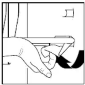
natural_image
Hand pressing a button on a device (no text or symbols visible)Turn the plastic clamp on the right side of the storage shelf upwards, as illustrated. Lift the right side a bit, and move the storage shelf to the desired position.
First place the left side of the storage shelf in the refrigerator wall, then the right side in the corresponding groove. Turn the plastic clamp downwards. Your storage shelf is fixated again.
Moving door bins
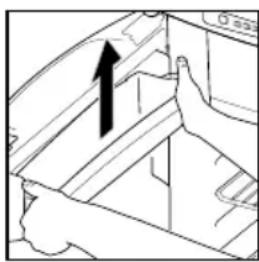
natural_image
Diagram of a hand holding a car interior with an upward arrow indicating motion (no text or symbols)Push a door bin out of the locking with both hands, as illustrated. Place this door bin back in the desired position and push it back on the locking. The door bin is fixated again.
Organising food
After a minimum of 8 hours of cooling, the food can be placed in the refrigerator. Do not completely cover the cooling fins with food, to preserve an optimal performance of the refrigerator. Make sure air can still circulate around the fins.
Note: To prevent your refrigerator from ice formation, always cover liquid products, let warm products cool down before placing them in the refrigerator and don't open the door longer than necessary.
Note: To reduce cooling time, store only pre-cooled foods in the refrigerator.
Note: To prevent the food from drying out or your refrigerator from odours, store food separately in closed boxes.
Use of freezer compartment
You can use the freezer compartment to keep food frozen or to make ice cubes with the special delivered tray.
CAUTION! Never keep carbonated liquids in the freezer compartment.
CAUTION! If the refrigerator has to perform for a longer period in internal vehicle temperature below 10°C, a constant regulation of temperature in the freezer compartment can't be guaranteed. The temperature can increase and the food may defrost in the freezer compartment.
Making ice cubes
Fill 2/3 of the ice cube with water and put the tray in the freezer compartment. Make sure you only use drinking water.
CAUTION! Never eat ice cubes or popsicles directly out of the freezer compartment. This can cause burn wounds.
Note: To quicken the process, make ice cubes at night, when the refrigerator has more capacity. Place the ice cube tray in an empty freezer on the bottom and the back.
While driving
⚠ WARNING: In Europe it is only allowed to run your refrigerator on gas while driving, if a gas system with break protection is installed and local regulations are respected.
Note: Because of varying outside conditions during driving, good performance on gas can't be guaranteed. Therefore Thetford does not advise to run your refrigerator on gas while driving.
Make sure all products in your refrigerator can't move while driving. Secure the bottles in the door with the bottle retainer and fixate all food on the storage shelves.
THETFORD REFRIGERATOR
Door lock
When you close and press the door of the refrigerator, the door locks automatically. While driving this door lock also secures the door. Some models have an extra security lock on the bottom of the refrigerator. To be sure the door will not open while driving, push the black security lock over the pin on the door.
⚠ WARNING: Never let children play or hide in the refrigerator. Children can be trapped and possibly suffocate.
Winter use
When you are going to use the refrigerator with an outside temperature below 10^ C, ,install a suitable winter cover.
This cover will protect your refrigerator against too cold air and makes sure the refrigerator will still perform optimally.
Make sure you remove the winter cover again once the temperature is above 10^ C.
Cleaning
It is important to regularly clean the refrigerator for optimal performance. Clean the inside with a soft cloth and a mild household cleaner. Use a wet, soft cloth for the outside of the refrigerator. Make sure the vents on the outside of the vehicle are always dust-tight.
⚠ WARNING: Never clean your refrigerator with soap or aggressive, caustic or soda-based cleaning agents.
⚠ WARNING: The loose parts of the refrigerator are not suitable for the dishwasher.
⚠ WARNING: Water through the vents may damage your refrigerator. Therefore install winter covers before washing your vehicle.
Switch off refrigerator
Before defrosting the refrigerator or sorting your vehicle, switch off the refrigerator. Push the on/off switch and hold it for 2 seconds to switch off the refrigerator. All lights will go out.
Defrosting
A layer of ice on the cooling fins will decrease the cooling capacity and durability of your refrigerator. Therefore your refrigerator is provided with an automatic defrost system, which prevents ice formation.
Despite this system, it is also possible to manually defrost your refrigerator on occasion. Remove all food, wrap it tightly in newspaper and put it on a cold place or in a insulated bag. Then open the doors. Put dry towels in the refrigerator to catch the remaining water. When the refrigerator is defrosted, thoroughly dry the inside.
⚠ WARNING: Do not speed up the defrosting process by removing the ice layer with force or sharp objects or by using a hairdryer.
Storage
If you do not expect to use your refrigerator for a longer period, it is important to thoroughly empty, defrost and clean the complete refrigerator. Then install the winter cover the vents, to protect your refrigerator during storage.
Note: To prevent odours and mould in the refrigerator, keep all doors open during the storage.
Rotate the hook at door lock 45 degrees and lock it in place by using the strike plate.
⚠ WARNING: Make sure the gas taps of the gas bottle are closed during storage.
⚠ WARNING: Water through the vents may damage your refrigerator. Therefore install winter covers before washing your vehicle.
Disposal
Your refrigerator has been designed and manufactured with high quality materials and components, which can be recycled and reused. The cooling system contains ammonia as the coolant and ozone friendly
cyclopentane as the blowing agent in the foam. The refrigerators are free of any CFCs / HCFCs and HFCs.
When your refrigerator has reached its end of life, dispose the product according to the local rules. Do not dispose the refrigerator with normal household waste. The correct disposal of your old product will help prevent potential, negative consequences to the environment and human health.
Questions?
If you require further information or have any questions about your refrigerator, please visit our website www.thetford-europe.com. If you still have questions, contact the Customer Service Department in your country or your holiday location.
For correct and efficient support, please ensure all relevant product type information is available.
THETFORD REFRIGERATOR TROUBLESHOOTING
Troubleshooting
Some problems are indicated through blinking lights on your control panel. First read the instructions below. If these will not solve the problem, contact your dealer or a Thetford Service Centre.
I just replaced the batteries, but the 'batteries empty' symbol is already
blinking. What is wrong? Check if you
have used only new 1.5 V AA / LR6 batteries.
Rechargeable batteries for this function do not work.
| Problem Actions you can take | |
| The refrigerator does not work on 230V - Check if the mains is available.- Try to run the refrigerator on another power source. | |
| The refrigerator does not work on 12 V - Check if the 12 V fuse in the fuse box of your motorhome or car is till operational.- Make sure the engine is running.- Try to run the refrigerator on another power source. | |
| The refrigerator does not work on gas - Check if the gas bottle is empty- Check if the valve of the gas bottle and all shut-off valves are open.- Switch the refrigerator off and on again.- Try to run the refrigerator on another power source. | |
FAQ
What can I do, when the refrigerator does not start? Check if you switched on the refrigerator according to the instructions, if the vehicle stands level or if there is an available energy source to start the refrigerator with. If none of this is the case, please contact your dealer or a Thetford Service Centre.
The refrigerator does not cool sufficiently, what can I do? Check if the vents aren't covered or blocked from the outside, if the refrigerator stands level, if the highest cooling setting of the refrigerator is selected, if the door of the refrigerator still closes properly or if there is not too much ice on the cooling fins. If none of this is the case, please contact your dealer or a Thetford Service Centre.
All lights on the control panel are blinking, what should I do? Please contact your dealer or a Thetford Service Centre.
No winter cover is supplied with my refrigerator, is this correct? The winter cover is an accessory for your refrigerator, which you can purchase at your dealer.
Spare Parts
Original Thetford spare parts are available through your own dealer or an authorised Thetford Service Centre.
Warranty
Thetford BV offers the end users of its products a three year guarantee. In the case of malfunction within the warranty period, Thetford will replace or repair the product at its discretion. In this case, the costs of replacement, labour costs for the replacement of defective components and/or the cost of the parts themselves will be paid by Thetford.
- To make a claim under this guarantee, the user must take the product to his dealer or an authorised Thetford Service Centre (www.thetford-europe.com). The claim will be assessed there.
- Components replaced during repair under guarantee become the property of Thetford.
- This warranty does not prejudice current consumer protection laws.
- This warranty is not valid in the case of products that are for, or are used from, commercial purposes.
-
Guarantee claims falling into one of the following categories will not be accepted:
-
the product has been improperly used, or the instructions in the manual have not been followed;
- the product has not been installed in accordance with the instructions;
- the product has been repaired by unauthorised Thetford Service Centre;
- the product code or serial ID has been changed;
-
the product has been damaged by circumstances outside the normal use of the product.
-
The guarantee is only valid for Thetford refrigerators that are built in a caravan or camper van.
Thetford is not liable for any loss and/or damage caused directly or indirectly by the use of the refrigerator.
DOMETIC REFRIGERATOR
Dometic absorption refrigerator
Guide to these operating instructions
Before you start using the refrigerator, please read the operating instructions carefully.
These instructions provide you with the necessary guidance for the proper use of your refrigerator. Observe in particular the safety instructions. Observation of the instructions and handling recommendations is important for dealing with the refrigerator safely and for protecting you from injury and the refrigerator from damage. You must understand what you have read before you carry out a task.
Keep these instructions in a safe place close to the refrigerator so they may be referred to at any time.
Copyright protection
The information, texts and illustrations in these instructions are copyright protected and are subject to industrial property rights.
No part of these instructions may be reproduced, copied or utilised in any other way without written authorisation by Dometic GmbH, Siegen.
Warranty
Warranty arrangements are in accordance with EC Directive 44/1999/CE and the normal conditions applicable for the country concerned.
For warranty or other maintenance, please contact our customer services department.
Any damage due to improper use is not covered by the warranty. The warranty does not cover any modifications to the appliance or the use of non-original Dometic parts. The warranty does not apply if the installation and operating instructions are not adhered to and no liability shall be entertained.
Limitation of liability
All information and guidance in these operating instructions were prepared after taking into consideration the applicable standards and regulations as well as the current state of the art. Dometic reserves the right to make changes at any time which are deemed to be in the interest of improving the product and safety.
Dometic will assume no liability for damage in the case of :
• Non-observation of the operating instructions
- Application not in accordance with the regulations or provisions
- Use of non-original spare parts
- Modifications and interferences to the appliance
- Effect of environmental influences, such as temperature fluctuations
- humidity
Customer services
Dometic offers a pan-European customer service network. Find your authorised customer service centre by calling the phone number indicated in the EuroService Network book, EuroService Network - which accompanies every refrigerator. You can also obtain the address information of the nearest customer service from www.dometic.com. When contacting Dometic Customer Services, please state the model, product number and serial number together with the MLC code, if applicable. You will find this information on the rating plate inside the refrigerator. We recommend that you note this data in the field provided on the front page of the fridge's operation manual.
Spare parts
Parts can be ordered throughout Europe from our customer services. Always give the model and product number when you contact the customer service! You will find this information on the rating plate inside the refrigerator.
Environmental notice
Refrigerators manufactured by Dometic GmbH are free of CFC/HCFC and HFC. Ammonia (a
natural compound of hydrogen and nitrogen) is used in the cooling unit as a coolant. Non-ozone-hazardous cyclopentane is used as a propellant for manufacturing PU foam insulation.
In order to ensure that the recyclable packaging materials are re-used, they should be sent to the customary local collection system.
The appliance should be transferred to a suitable waste disposal company that will ensure re-use of the recyclable components and proper disposal of the rest. For eco-friendly draining of the coolant from all absorber refrigeration units, a suitable disposal plant should be used.
Energy-saving tips
- At an average ambient temperature of 25^ C, it is sufficient to operate the refrigerator at middle thermostat setting.
- Where possible, always store precooled products.
- Do not expose the refrigerator to direct sunlight.
- Ensure that air circulation of the cooling unit is not obstructed.
- Defrosting at regular intervals saves energy (see "Defrosting"). Open the refrigerator door only for a short period of time when removing products.
- Run the refrigerator for about 12 hours before filling it.
Safety instructions
Application according to regulations
This refrigerator is designed for installation in recreation vehicles such as caravans or motorhomes. The appliance has been type approval tested for this application in accordance with the EC Gas Directive.
The refrigerator is to be used solely for storing foodstuffs.
⚠ WARNING: Do not lift the coupling head by hand when hitching the caravan to the car. Always raise and lower the coupling head by winding the handle on the jockey wheel up and down.
User's responsibility
Anyone operating the refrigerator must be familiar with the safe handling and understand the advice in these operating instructions. Children may only operate the appliance, if they have been made aware of how to operate the refrigerator safely and the dangers attending incorrect operation.
Protection of children when disposing of the equipment
⚠ WARNING: When disposing of the refrigerator, detach all refrigerator doors and leave the storage racks in the refrigerator. In this way inadvertent entrapment and suffocation is prevented.
Working upon and checking the refrigerator
⚠ WARNING: Work on gas equipment, exhaust system and electrical facilities must be carried out by authorised personnel only. Substantial damage to property and / or injury to persons can arise through unprofessional procedures.
DOMETIC REFRIGERATOR
⚠ WARNING: Never use an unshielded flame to check gas bearing parts and pipes for leakage! There is a danger of fire or explosion.
⚠ WARNING: Never open the absorber cooling unit! It is under high pressure. There is a danger of injury.
Information on coolant
Ammonia is used as a coolant. This is a natural compound also used in household cleaning agents (1 litre of Salmiak cleaner contains up to 200g of ammonia - about twice as much as is used in the refrigerator). Sodium chromate is used for corrosion protection (1.8% by weight of the solvent).
In the event of leakage (easily identifiable from the strong odour), proceed as follows:
- Switch off the appliance.
• Air the room thoroughly. - Inform authorised customer services.
Note: For your safety it was ascertained in an expert's report that no impairment of health exists when the coolant is discharged.
Operating the refrigerator with gas
It is imperative that the operating pressure corresponds to the data specified on the rating plate of the appliance. Compare the operating pressure of the rating plate with the data specified on the pressure reducing valve of the liquid gas cylinder.
⚠ WARNING: Operating the appliance with gas is not permitted
- At petrol stations
- On ferry boats
- While transporting the caravan / motorhome by a transporter or breakdown vehicle.
There is danger of fire!
Leave the equipment switched off.
Safety instructions when storing foodstuffs
Instructions for storing food in a refrigerator:
No refrigerator of any kind can improve the quality of the food; refrigerators can only maintain the food's quality for a short duration as from the time of storing it.
Please observe the following particular conditions for storing food in a refrigerator that is built into a vehicle:
- A change in the climatic conditions such as temperature fluctuations
- High temperatures inside the vehicle when it is closed and parked in direct sunlight (temperatures are possible up to 50°C)
- Use of the refrigerator during travel with the power supply of 12V DC
- A refrigerator built in behind a window and exposed to direct sunlight
- Storing the products too soon, i.e. shortly after starting up the appliance for use
Under these particular conditions the refrigerator cannot guarantee reaching the temperature needed for perishables.
Perishables include all products with a stipulated use-by date and a minimum storage temperature of +4°C or less, especially for meat, poultry, fish, sausages, pre-packed foods.
- Pack raw and cooked foods separately (e.g. in containers, aluminium foil, etc.).
- Only remove the outside packaging of single packs if all the necessary information, e.g. the use-by date, can also be read on the single packs.
- Do not leave cooled goods outside the refrigerator for too long.
- Place the foods with the next use-by date at the front, accordingly.
-
Pack away any left-over food and eat at the first opportunity.
-
Wash your hands before and after handling any food.
- Regularly clean the inside of the refrigerator.
Please observe the instructions and information regarding the use-by date on the outside packaging of the food.
Please observe section "Cleaning" of this instruction.
Refrigerator rating plate
The rating plate is to be found on the inside of the refrigerator. It contains all important details of the refrigerator. You can read off from this the model identification, the product number and the serial number. You will need these details whenever you contact the customer service centre or when ordering spare parts.
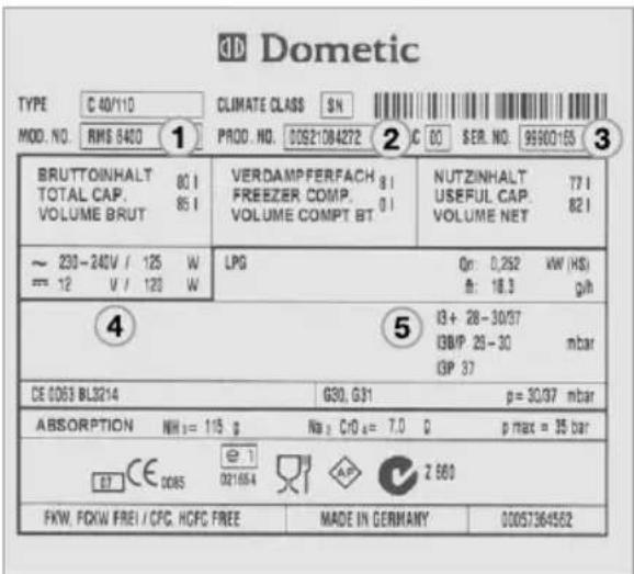
1 - Model Number
2 - Product Number
3 - Serial Number
4 - Electrical rating details
5 - Gas pressure
The cooling unit's performance is influenced by ambient temperatures. Please select the medium setting for ambient temperatures between +15°C and +25°C (refer to Setting of cooling compartment temperature.) The unit operates within its optimum performance range.
Dometic refrigerators work according to the absorption principle. For physical reasons, an absorption system responds slowly to
changes made by the thermostat controller, by loss of cooling energy through opening the door storing food. The devices meet the cooling performance requirements of the Climatic Clas SN acc. to EN/ISO 7371 in the temperature range of +10°C to +32°C ambient temperature.
For temperatures below +10°C, winter covers should be installed. For ambient temperatures exceeding +32°C for a longer period of time, it is recommended installing Dometic additional fan (item no. 241 2985 - 00).
Description of refrigerator
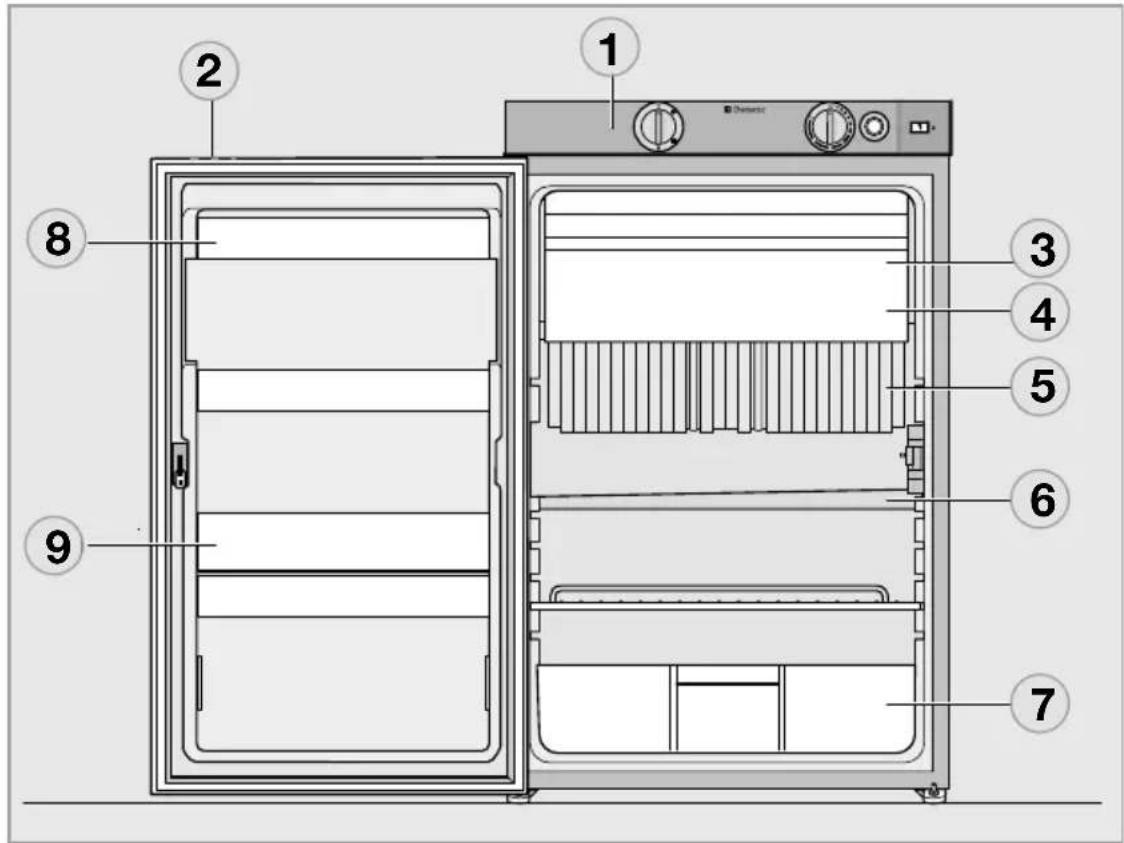
(Appearance is model specific)
1 - Operating controls
2 - Door locking button
3 - Freezer compartment (removable)
4 - Insertable grid shelf (available as option, to be used when freezer compartment is removed)
5 - Post-evaporator for cooling compartment
6 - Condensation water drain channel
7 - Vegetable bin
8 - Upper door shelf with flap, egg shelf available as option may be inserted
9 - Lower door shelf with bottle holders
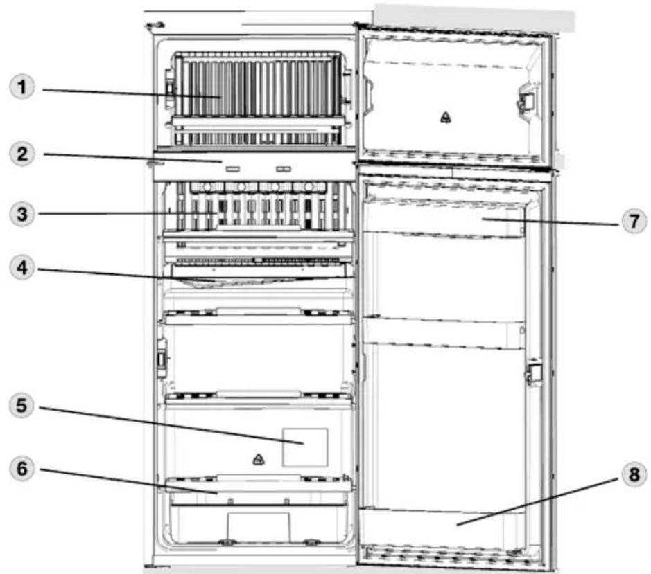
1 - Freezer compartment
2 - Operating controls
3 - Post evaporator for cooling compartment
4 - Condensation water drain channel
5 - Data plate
6 - Vegetable bin
7 - Upper door shelf with flap, egg shelf available as option may be inserted.
8 - Lower door shelf with bottle holders
DOMETIC REFRIGERATOR
Refrigerator operation
The refrigerator is equipped to operate on three power modes:
• Mains voltage (230V AC)
- Direct-current voltage (12V DC)
•Gas (liquid gas propane/butane)
Select the desired power mode by the energy selector switch (battery igniter type models) or the MODE button (MES, AES). Appliances with automatic energy selection (AES) are additionally provided with “automatic mode” function. The AES system automatically selects the best energy source for each particular situation.
Cleaning
Before starting up the refrigerator, it is recommended that you clean it inside and repeat this at regular intervals.
Use a soft cloth and lukewarm water with a mild detergent. Then wipe out the appliance with clean water and dry thoroughly.
natural_image
Illustration of a plastic bottle and a cloth-like object (no text or symbols)Fig. 6
To avoid material alterations, do not use soap or hard, abrasive or soda-based cleaning agents.
Do not allow the door seal to come into contact with oil or grease.
Maintenance
- In compliance with the applicable regulations, please note that the gas unit and the connected ventilation ducts must be checked by authorised technical personnel after first use and after every other year for compliance with the European Standard EN 1949. A test certificate has to be issued. It is the user's responsibility to arrange this test.
- The gas burner must be inspected and cleaned as necessary at least once a year. When using liquefied petroleum gas (tank or refill cylinders) the maintenance interval is reduced to half-yearly or quarterly. Keep the evidence of maintenance work carried out on your refrigerator.
- Work on gas and electrical equipment shall be carried out by qualified personnel only.
It is recommended that this is carried out by an authorised customer services department.
We recommend maintenance following an extended shutdown of the vehicle. Please contact our customer services.
Manual energy selection / automatic ignition (RM 8xx1) MES (fridge models)
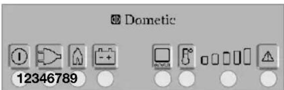
Fig. 7
1 - Power ON/OFF switch
2 - Energy selector button 230V \~
3 - Energy selector button GAS
4 - Energy selector button 12V =
6 - Temperature level selection
7 - Temperature level display
8 - Indicator LED failure / Reset button
GAS FAILURE
Switching ON/OFF
- Switch ON by pressing button (1), 2s
- Switch OFF by pressing button (1), > 2s
230V AC operation
- Select "Mains voltage" by pressing button (2)
- Set temperature step by pressing button (6)
12V DC operation (vehicle's battery)
- Select "Battery voltage" by pressing button (4)
- Set temperature step by pressing button (6)
Gas operation
- Select "Gas" by pressing button (3)
- Set temperature step by pressing button (6)
RM 8XX1 MODELS MES appliances (manual energy selection)
Electrical operation
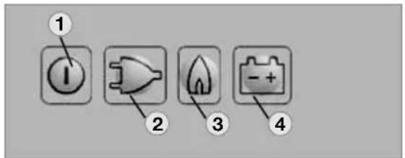
Fig. 16
To start the refrigerator, press button (1) for 2 seconds.
The refrigerator starts with the last selected type of energy.
230V operation :
Press button (2):

12V operation :
Press button (4) :

Gas operation
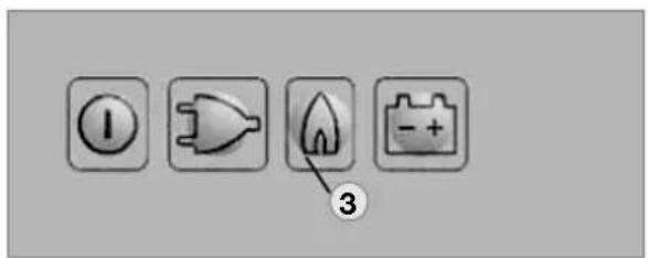
Fig. 17
Gas operation :
Press button (3) :

The ignition process is activated automatically by means of an automatic igniter.
Note: The flame extinguishes after reaching the preset cooling compartment temperature and ignites again if the cooling compartment temperature increases again. If the flame is not lit after the first ignition attempt, the automatic igniter repeats the ignition twice (duration 30 s) at time intervals of 2 minutes. If the flame is not lit afterwards, a fault is indicated.
Setting of cooling compartment temperature
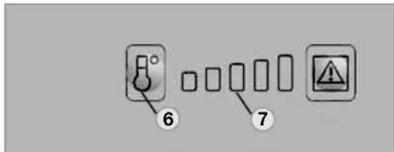
Fig. 18
Select the desired cooling compartment temperature by pressing button (6).
The LED display (7) of the selected temperature setting is illuminated.
The scale starts with MIN position at the left LED position (small bar = highest temperature) and climbs up to MAX position at the right LED position (large bar = lowest temperature).
Note: The temperature levels do not relate to absolute temperature values.
Additional features
- The brightness of the display reduces after a few seconds if no other buttons are pressed. The indicator lights again if a button is pressed. Press the button again to activate the required function.
- Failures are indicated by flashing of the failure indicator LED.
- Should the door be kept open for too long (more than 2 minutes), an acoustic signal is initiated (pulsing whistle tone).
- Should the electronic control detect any failure, an acoustic signal will sound (pulsing whistle tone). At the same time the display starts flashing (for trouble-shooting, please refer to page 157).
DOMETIC REFRIGERATOR
Gas operation with internal batteries (optional)
An optional battery compartment in the electronics case for internal (self-contained) power supply of the electronics is available for the model variants RM 8xx1 and RM 8xx5 (appliances with electronics).
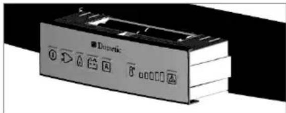
Fig. 21
Load the battery compartment with batteries (8 x AA 1.5 V) before operating the refrigerator.
All operating modes can be selected while the on-board 12 V DC power supply is active. The internal voltage is disconnected.
If the on-board 12 V DC power supply is not present or there is an interruption of the mains power supply during operation, the electronics automatically switch to the internal (battery) power supply. The refrigerator can now only be operated in the gas mode.
All LED indicators except the GAS LED are not lit during operation with internal batteries. The GAS LED flashes every 15 seconds.
If a button is pressed, the temperature level LEDs (7) also light.
If the battery voltage is too low, an acoustic signal (whistle tone) sounds every 15 seconds. Then replace the batteries in the battery compartment.
Inserting / changing the batteries
- Switch off the refrigerator, as described in section 'Shutting of the refrigerator'
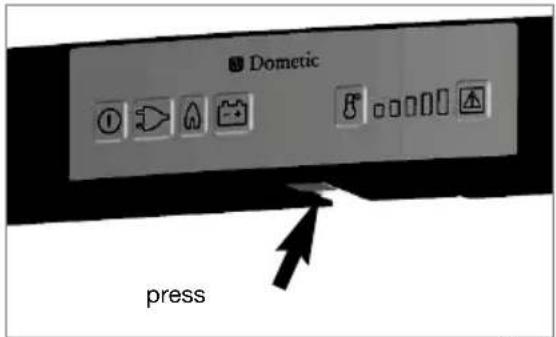
Opening battery compartment
Fig. 22
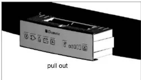
Fig. 23
Note: Batteries (8 x AA 1.5V) are not included!
⚠ WARNING:
- Observe the correct polarity!
- Do not connect non-rechargeable batteries to a charger.
- Remove rechargeable batteries from the battery compartment before charging.
- Avoid short circuits on the contacts in the battery compartment!
- Remove discharged batteries.
- Remove the batteries from the battery compartment if the refrigerator will not be used for a long time.
- Do not mix different types of batteries.
Explanation of operating controls
The control panel buttons are not accessible when the refrigerator door is closed. Open the bottom door to reach the operating buttons.
Depending on the door opening direction, there are two LEDs on the left or right edge of the control panel. The outer LED (1) indicates that the refrigerator is operational (blue). The other LED (2) lights red in the event of a fault.
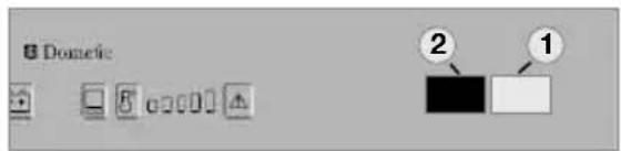
Fig. 4
Refrigerators for self-contained (gas) operation contain two battery compartments in the control panel which are located on the left and right next to the button bar.
Fig. 5
Fig. 6
Manual energy selection / automatic ignition (RMD 8xx1) MES
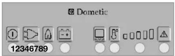
Fig. 7
1 - Power ON/OFF switch
2 - Energy selector button 230V \~
3 - Energy selector button GAS
4 - Energy selector button 12V =
6 - Frameheating
7 - Temperature level selection
8 - Temperature level display
9 - Indicator LED failure / Reset button GAS FAILURE
Switching ON/OFF
- Switch ON by pressing button (1), 2s
- Switch OFF by pressing button (1), > 2s
230V AC operation
- Select "Mains voltage" by pressing button (2)
- Set temperature step by pressing button (7)
12V DC operation (vehicle's battery)
- Select "Battery voltage" by pressing button (4)
- Set temperature step by pressing button (7)
Gas operation
- Select "Gas" by pressing button (3)
- Set temperature step by pressing button (7)
RMD 85x1 models MES-appliances (manual energy selection)
Electrical operation
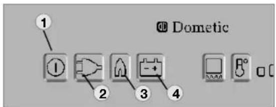
Fig. 9
To start the refrigerator, press button (1) for 2 seconds.
The refrigerator starts with the last selected type of energy.
230V operation :
Press button (2):

12V operation :
Press button (4):

DOMETIC REFRIGERATOR
Gas operation
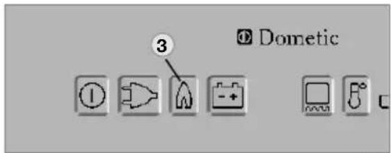
Fig. 10
Gas operation :
Press button (3) :

The ignition process is activated automatically by means of an automatic igniter.
Note: The flame extinguishes after reaching the preset cooling compartment temperature and ignites again if the cooling compartment temperature increases again. If the flame is not lit after the first ignition attempt, the automatic igniter repeats the ignition twice (duration 30 s) at time intervals of 2 minutes. If the flame is not lit afterwards, a fault is indicated.
Setting of cooling compartment temperature
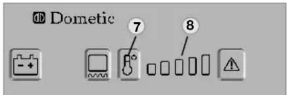
Fig. 11
Select the desired cooling compartment temperature by pressing button (7).
The LED display (8) of the selected temperaturesetting is illuminated.
The scale starts with MIN position at the left LED position (small bar = highest temperature) and climbs up to MAX position at the right LED position (large bar = lowest temperature).
Note: The temperature levels do not relate to absolute temperature values.
Additional features
- The brightness of the display reduces after a few seconds if no other buttons are pressed. The indicator lights again if a button is pressed. Press the button again to activate the required function.
- Failures are indicated by flashing of the failure indicator LED.
- Should the door be kept open for too long (more than 2 minutes), an acoustic signal is initiated (pulsing whistle tone).
- Should the electronic control detect any failure, an acoustic signal will sound (pulsing whistle tone). At the same time the display starts flashing (for trouble-shooting, please refer to page 157).
Gas operation with internal batteries (optional)
An optional battery compartment in the electronics case for internal (self-contained) power supply of the electronics is available for the model variants RMd 85x1 and RMD 85x5 (appliances with electronics).
natural_image
Pure electrical circuit lines without any symbolsFig. 14
Load the battery compartment with batteries (8 x AA 1.5 V) before operating the refrigerator.
All operating modes can be selected while the on-board 12 V DC power supply is active. The internal voltage is disconnected.
If the on-board 12 V DC power supply is not present or there is an interruption of the mains power supply during operation, the electronics automatically switch to the internal (battery) power supply. The refrigerator can now only be operated in the gas mode.
All LED indicators except the GAS LED are not lit during operation with internal batteries. The GAS LED flashes every 15 seconds.
If a button is pressed, the temperature level LEDs (7) also light.
If the battery voltage is too low, an acoustic signal (whistle tone) sounds every 15 seconds.
Then replace the batteries in the battery compartment.
Inserting / changing the batteries
Switch off the refrigerator, as described in section 4.14 Shutting of the refrigerator.
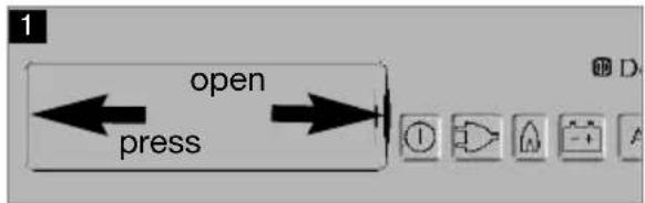
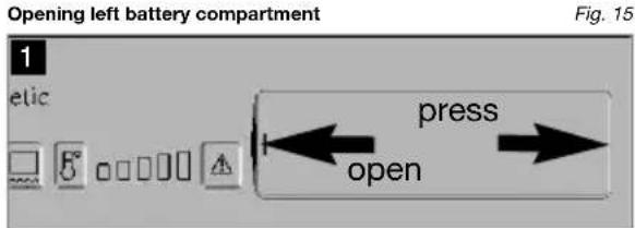
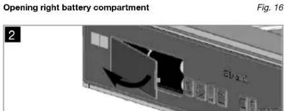
Note: Batteries (8 x AA 1.5V) are not included!
WARNING:
- Observe the correct polarity!
- Do not connect non-rechargeable batteries to a charger.
- Remove rechargeable batteries from the battery compartment before charging.
- Avoid short circuits on the contacts in the battery compartment!
- Remove discharged batteries.
- Remove the batteries from the battery compartment if the refrigerator will not be used for a long time.
- Do not mix different types of batteries.
Frame heating (fridge freezer models only)
All fridge freezer models are equipped with a frame heating (12VDC/3,5W) around the freezer compartment. During summer months with high temperatures and humidity the metal frame may have water droplets forming. To evaporate these droplets switch on the frame heating with button (6).
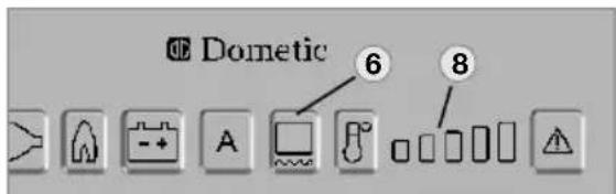
Fig. 18
The operating time of the frame heater can be set to 2 hours, 5 hours or continuous operation. After selecting the operating time using the button (6), the temperature level indicator (8) is extinguished for a short time to show the set operating time for a few seconds. The display then returns to the temperature level indicator.
Operating time: 2 hours
Press button (6) once Display

Operating time: 5 hours
Press button (6) twice Display

Permanent operation
Press button (6) three times Display

DOMETIC REFRIGERATOR
⚠ WARNING: In order to prevent discharge of the onboard battery, change the frame heater from continuous operation to another operating time or switch it off.
Note: The frame heater is active for 30 minutes after switching on and then switches itself off and on again at time intervals of 5 minutes.
Door locking
⚠ WARNING: As a basic rule, shut and lock the refrigerator before you start your journey!
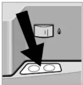
natural_image
Diagram showing a black arrow pointing downward to a container with liquid, next to two circular components (no text or symbols)Fig. 24
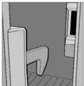
natural_image
3D rendering of a simple room corner with a door and window (no text or symbols)Fig. 25
Open the door by pressing the locking button and pull open (see Fig. 24).
Shut the door again by pushing it to close. The snapping into the lock can be heard.
While the vehicle is parked, the locking hook may be fixed to facilitate opening of the door (Fig. 26-27).
Fastening and releasing the door lock hook when parking the vehicle
If the vehicle is parked for a longer period of time, the locking hook may be clamped by means of a lockbar. The door may now be opened by just pulling it without need of pressing the locking button.
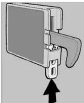
natural_image
Mechanical component diagram showing a bracket with a handle and arrow indicating upward motion (no text or symbols)Fastening
Fig. 26
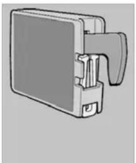
natural_image
Illustration of a mechanical device with a handle and internal components (no text or symbols)Fig. 27
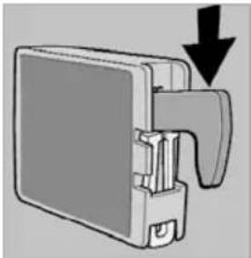
natural_image
Diagram of a mechanical device with a downward arrow indicating force or direction (no text or symbols present)Releasing
Fig. 28
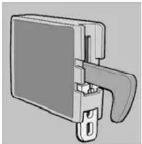
natural_image
Technical illustration of a mechanical component with a handle and mounting bracket (no text or symbols)Fig. 29
Lighting
The interior lighting is controlled using a door contact. Should the door be kept open more than 2 minutes, an acoustic signal is initiated (pulsing whistle tone). (except for models with battery igniter).
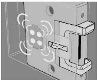
natural_image
Technical illustration of a mechanical assembly with circular motion indicators (no text or symbols)Fig. 30
Note: Please contact the authorized Dometic Service if a failure occurs.
Positioning the storage racks
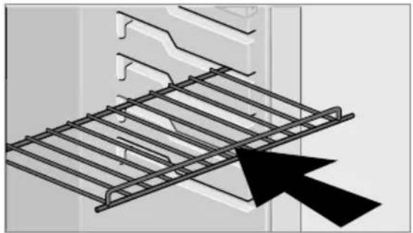
natural_image
Diagram of a metal grid structure with an arrow pointing to it, no text or symbols presentFig. 31
The storage racks may be pulled out by smoothly lifting them and may be positioned as desired.
Removable freezer compartment
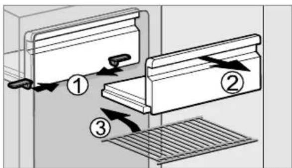
Fig. 32
To enlarge the cooling compartment, just remove the freezer compartment.
- Unlock the freezer compartment on both sides.
- Pull the freezer compartment out. Store the freezer compartment safely in order to prevent damage
Note: Once the freezer compartment is removed, an additional storage rack (3.) may be installed. The storage rack is a piece of extra equipment and may be obtained by Dometic.
Winter operation
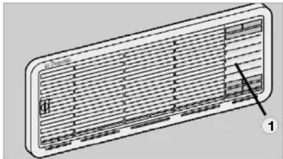
natural_image
Diagram of a rectangular air conditioner unit with ventilation grilles and ventilation slots (no text or symbols)Fig. 35
In winter, check that the ventilation grilles and the exhaust duct system (1) have not been blocked by snow, leaves, etc.
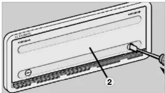
Fig. 36
When the outside temperature falls below +10°C, the winter covers should be fitted. This protects the unit from excessively cold air which could have adverse effects on the performance of the unit.
Covers may be supplied as part of the specification of your caravan or alternatively are available through most Swift Group Dealers.
Note: You should also attach the winter covers if the vehicle is taken out of service for a longer period of time or while it is being cleaned from the outside.
Winter operation (fridge freezer models)
In winter, check that the ventilation grilles and the exhaust duct system (1) have not been blocked by snow, leaves, etc.
Note: Winter covers are not supplied as standard on most models.
DOMETIC REFRIGERATOR
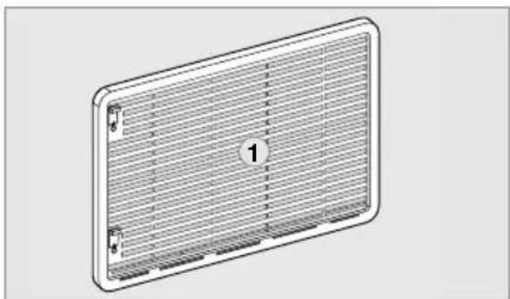
natural_image
Illustration of a rectangular electronic device with a grid-patterned panel and labeled component '1' (no text or symbols on the panel itself)Fig. 32
When the outside temperature falls below +10°C, the winter cover (2) should be fitted. This protects the unit from excessively cold air which could have adverse effects on the performance of the unit.
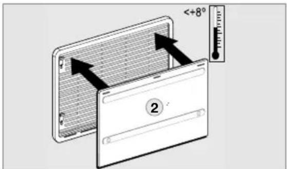
Fig. 33
You should also attach the winter covers if the vehicle is taken out of service for a longer period of time or while it is being cleaned from the outside.
Storing food and making ice cubes
Storing products in the cooling compartment
- Switch the refrigerator on approx. 12 hours before filling it.
- Always store pre-cooled foods in the refrigerator. Make sure that the food is well cooled when it is bought and also when transporting it. Use insulated cooling bags.
-
Open the refrigerator door only for a short period of time when removing products.
-
Products must be packed - best of all in closed containers, wrapped in aluminium foil or similar - and stored separately from each other, in order to prevent drying out or odours.
- Allow foods that have been warmed up to cool down before storing.
- Avoid storing products in the refrigerator that could emit volatile flammable gases.
- Do not overfill the storage grids and compartments to prevent obstructing the internal air circulation.
- Maintain a clearance of approx. 5 - 10 mm between chilled products and post-evaporator ("cooling fins").
- Do not expose the refrigerator to direct sunlight. Please bear in mind that the temperature inside a closed vehicle increases sharply if exposed to sunlight and that this can reduce the efficiency of the refrigerator.
- Ensure that air circulation of the cooling unit is not obstructed. Keep the ventilation grilles free from obstructions.
Storing products in the freezer compartment
- Do not keep carbonated drinks in the freezer.
- The freezer compartment is suitable for making ice cubes and for short-term storage of frozen food. It is not suitable as a means of freezing foods.
When ambient temperatures are lower than +10°C and the refrigerator is exposed to these temperatures for extended periods of time, an even regulation of freezer temperature cannot be guaranteed for system related reasons. This can cause the temperature in the freezer to rise and the stored goods to melt.
Refrigerator compartments
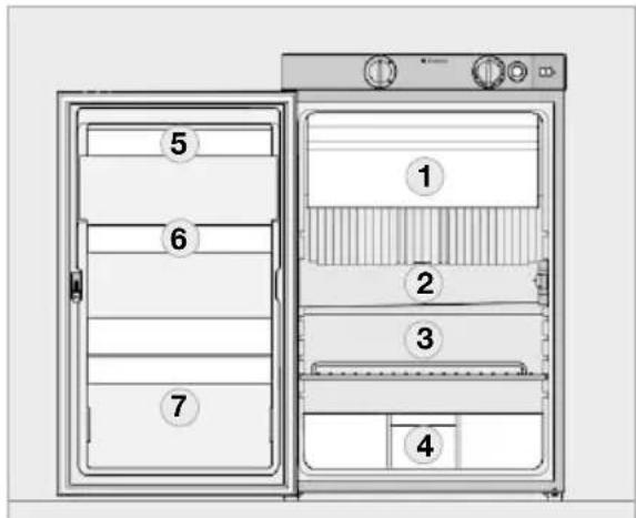
Fig. 37
1 - Freezer compartment: already frozen food (deep-frozen food)
2 - Middle compartment: Dairy products, convenience food
3 - Bottom compartment: Meat, fish, food for defrosting
4 - Vegetable compartment: Salads, vegetables, fruit
5 - Top door shelf: Eggs, butter
6 - Middle door shelf: Cans, dressings, ketchup, jam
7 - Bottom door shelf (drinks compartment): Drinks in bottles or bags
Positioning the storage racks
The storage racks may be pulled out by loosening the two locking devices (1) underneath. For loosening pull the slider to the middle, for fastening pull them sidewards.
Two of the storage racks are secured. In this way inadvertent entrapment and suffocation of children is prevented, if the storage racks are removed. To protect children it must be avoided to create space for children in the cooling compartment.
⚠ WARNING: Do not remove these storage racks. Thus children have no space to be entrapped in the refrigerator.
If it is necessary to remove these storage racks (i.e. for cleaning) loosen the locking pins (2) at first as shown, by means of a suitable screw driver.
Put in place the locking pins after removing the storage racks.
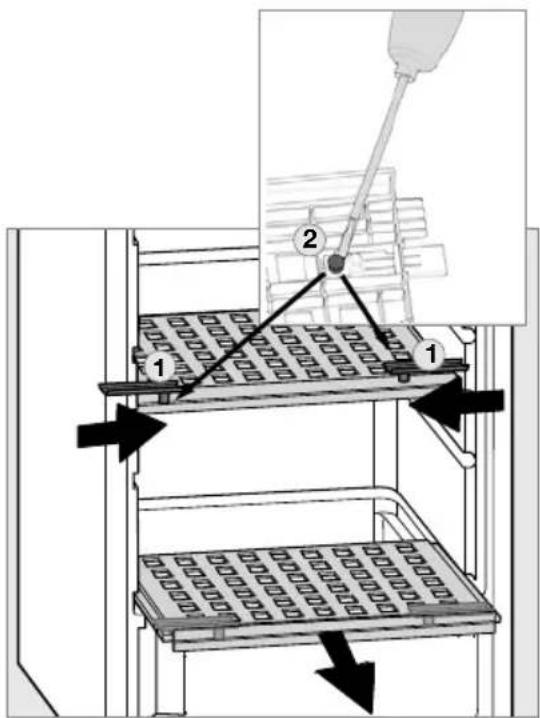
Fig. 26
DOMETIC REFRIGERATOR
Shutting off the refrigerator
Fig. 41
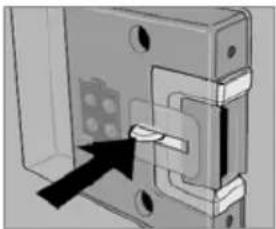
natural_image
Mechanical assembly diagram showing a bracket with mounting holes and a highlighted component (no text or symbols)Fig. 42
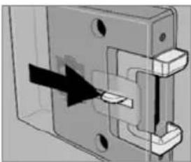
natural_image
Mechanical assembly diagram showing a component with arrows indicating direction (no text or symbols)Fig. 43
- For battery igniter models, set energy selector switch (1) to position "OFF". The appliance is switched off (Fig. 40).
- Switch off MES and AES models by pressing button (2). Keep button (2) pressed for 3 seconds. The display disappears and the appliance is fully switched off (Fig. 40).
- Release the locking mechanism of the door lock by pushing it and shift it to the front. If the door is shut in this position, a small gap is nevertheless kept open to prevent formation of mildew.
- If the refrigerator is to be taken out of service for an extended period of time, close the onboard shut-off valve and the cylinder valve.
Troubleshooting
Failure: The refrigerator does not cool sufficiently.
| Possible cause Action you can take | |
| Inadequate ventilation to the unit Check that the | ventilation grilles are not covered |
| Thermostat setting is too low Set thermostat to | a higher level |
| The condenser is heavily frosted Check that the | refrigerator door closes properly |
| Too much warm food has been stores inside within a short period of time | Allow warm food to cool down before storage |
| The appliance has been running for only a short period of time | Check whether the cooling compartment works after approx 4-5 hours |
| Ambient temperatures too high Regularly remove | ve ventilation grilles. |
Failure: The refrigerator does not cool in gas operation mode.
| Possible cause Action you can take | |
| Gas cylinder empty Change gas cylinder | |
| Is the upstream shut-off device open? Open shut-off device | |
| Air in the gas pipe? Switch off the appliance and start again.Repeat this procedure 3-4 times, if necessary. |
Failure: The refrigerator does not cool in 12 V operation.
| Possible cause Action you can take | |
| On-board fuse defective Fit new fuse | |
| On-board battery displaced Check battery, charge it | |
| Engine not running Start engine | |
| Heating element defective (please refer to failure indication) | Please inform the Dometic Customer Services. |
DOMETIC REFRIGERATOR TROUBLESHOOTING
Failure: The refrigerator does not cool in 230 V operation.
| Possible cause Action you can take | |
| On-board fuse defective Fit new fuse | |
| Vehicle not connected to mains supply voltage | Make a connection to a mains power supply |
| AES: Gas operation despite connection to the mains supply voltage? | Appliance switches to gas operation due to insufficient mains supply voltage (automatically switches back to 230 V operation) |
| Heating element defective (please refer to failure indication | Please inform Dometic Customer Services |
Information on failure display and trouble-shooting
- Refrigerators with an electronics system (MES, AES) indicate the occurrence of a malfunction by the LED or display flashing.
- If a malfunction occurs, the indicator LED "Failure" (8) flashes simultaneously. In the case of AES models an acoustic alarm sounds.
Before notifying the authorised Service Center, please check whether:
- the instructions in section "Operating the refrigerator" have been observed.
- the refrigerator stands level.
- it is possible to operate the refrigerator with any available power source.
Status indicators
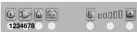
MES
Fig. 51
1 - Button ON / OFF
2 - Energy selector switch 230 V AC
3 - Energy selector switch GAS
4 - Energy selector switch 12V DC
6 - temperature level button
7 - temperature level display
8 - fault LED / GAS FAULT reset button
Operation with on-board
12 v power supply
| Indicator Fault Remedy | ||
| (2) and (8) flashing and acoustic signal 20s | 230 V mode: "230V" not available or voltage too low | Check mains power connection, mains voltage, fuse |
| (4) and (8) flashing and acoustic signal 20s | 12 V mode: "12V" not available or voltage too low | Check 12V connection, on-board battery, fuse |
| (3) and (8) flashing and acoustic signal 20s | Gas mode: Flame not ignited | Check gas supply (gas bottle, gas valve)Press the (8) button after clearing the fault |
| Acoustic signal, 15s at two minute intervals | Interior lighting is switched on | Close door, check door contact |
| (2) and (7) flashing and acoustic signal 20s | 230 V mode: 230V heating element defective | Arrange replacement of 230V heating element, contact Customer Service |
| (4) and (7) flashing and acoustic signal 20s | 12 V mode: 12V heating element defective | Arrange replacement of 12V heating element, contact Customer Service |
| (7) flashing and acoustic signal 20s | Temperature sensor without contact or defective | Contact Customer Service |
| (3) and (7) flashing and acoustic signal 20s | Burner defective or cooling unit defective | Check burner, burner nozzles, if necessary contact Customer Service and arrange replacement |
DOMETIC REFRIGERATOR TROUBLESHOOTING
Operation with batteries (internal power supply)
| Indicator Fault Remedy | ||
| (3) and (8) flashing brightly | Flame not ignited Check gas supply (gas bottle, gas valve)Press the (8) button after clearing the fault | |
| (3) and (7) flashing brightly | Burner defective or cooling unit defective | Check burner, burner nozzles, if necessary contact Customer Service and arrange replacement |
| Acoustic signal at 15 second intervals | Undervoltage detection (internal batteries) | Replace batteries |
| Automatic switching from external to internal power supply does not function (absence of the onboard 12V power supply for the electronics) | Refrigerator does not function, gas operation not possible although the batteries are inserted | Switch off the refrigerator and start againThe onboard power supply was interrupted during the starting of the gas operationNote: No automatic switching is performed during the ignition. |
Cooker 3 Burner + Hotplate operation
Burner operation
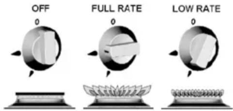
Fig. 1
Important
- Although each burner will support pans from 10 to 22cm, care should be taken not to overload the appliance as performance may be reduced.
- The following pan sizes are the maximum we recommend:- Electric Hotplate:- ∅180mm Auxiliary Burner:- ∅200mm Semi-Rapid Burner:- 2x ∅200mm or 1x ∅220mm with 1x ∅180mm
- When using small pans the flames should not spread beyond the base of the pan as this will reduce the efficiency of the burner.
- Avoid old or misshapen pans as these may cause instability.
- The lid must be opened fully prior to using the hotplate burners.
Using the Hotplate Gas Burners
- Ensure gas cylinder/supply is connected and turned on. In the event of a gas smell turn off at gas cylinder/mains and contact supplier.
- Flame supervision: Each burner is controlled individually and is monitored by a thermocouple probe. In the event of the burner flames being accidentally extinguished, turn off the burner control and do not attempt to re-ignite the burner for at least one minute.
- To light: Push in the control knob and turn to full rate – see Fig.1. Hold a lighted match or taper to the burner and push the control knob in and hold. It is necessary to hold
the knob depressed after the burner has ignited for approximately 10 - 15 seconds, to allow the thermocouple probe to reach temperature, before releasing the knob. Should the flame go out when the knob is released, the procedure should be repeated holding the knob depressed for slightly longer.
- For models fitted with Spark Ignition the procedure is similar except that the burner can be ignited by depressing the ignition button, which is located on the fascia. If the burner has not lit within 15 seconds the control knob should be released and the burner left for at least 1 minute before a further attempt to ignite the burner.
- For simmering, turn the knob further anticlockwise to the low rate position.
- To turn off: Turn the control knob until the line on the control knob is aligned with the dot on the control panel. Always make sure the control knob is in the off position when you have finished using the hotplate burners.
Using the Electric Hotplate
Ensure the electricity is switched on.
The hotplate control is numbered from 1 to 6. To turn it on, rotate the knob either clockwise or anti-clockwise to the required position. Position 1 is the coolest setting.
To turn the hotplate off, rotate the knob until the line or pointer on the knob lines up with the zero on the control panel.
The hotplate is a sealed construction and transfers heat through conduction. For maximum efficiency a correctly sized pan with a flat heavy gauge base should be used. Pan size should be the same or slightly larger (up to 1" / 2.5cm oversize).
Before using your hotplate for the first time, we recommend that you prime and then season it.
COOKER OPERATION
To prime the Hotplate
Switch on the hotplate for a short period, without a pan, to harden and burn off the coating.
Use a medium to high setting for 3 – 5 minutes. A non toxic smoke may occur during this process. Allow it to cool, then season.
To season the Hotplate
First heat the hotplate for 30 seconds on a medium setting, then switch off. Pour a minimal amount of unsalted vegetable oil onto a clean dry cloth or paper towel, and apply a thin coat of oil to the hotplate surface. Wipe off any excess oil, then heat the hotplate on a medium setting for 1 minute. Occasional seasoning will help to maintain the Hotplate's appearance.
⚠ WARNING:
- Glass lids may shatter when heated. Turn off the hotplate and allow it to cool before closing the glass lid.
- Remove all spillage from the surface of the glass lid before opening.
- The glass lid has the tendency to snap shut towards the end of lowering.
This is caused by the travel lock action of the hinges as it is activated.
Make sure all fingers are removed from appliance when closing the lid.
⚠ WARNING: The use of the electric hotplate and gas hobs will generate heat. We recommend, to avoid excess build-up of heat around the cooker area, the window is left opened when cooking to allow for additional ventilation.
Important
- Depending on specification, your appliance may be fitted with a glass lid shut-off system, which cuts off the power to all hotplate burners (gas and electric) if the lid is closed.
- Ensure the glass lid is in the open and upright position before turning on the hotplate burners.
- Not all models are fitted with the shut-off system.
Operation
WARNING
On separate oven & Grill cookers
- The grill area can get hot when the oven is in use, even if the grill is switched off.
- Care should be taken when removing pans from the grill, i.e. use of oven gloves, and by making use of the removal grill pan handle.
- Care should be taken when using oven as knobs and handle may become hot.
Important
- The grill pan supplied is multi functional, for use in grill or oven.
- The handle design allows removal or insertion whilst the pan is in use.
- Always remove the handle when the pan is in use.
- The grill MUST only be used with the door open.
Using the Grill
- Ensure gas cylinder/supply is connected and turned on. In the event of a gas smell turn off at gas cylinder/mains and contact supplier.
- To light: Open door, push in the control knob and turn to full rate – see Fig 1 (page 159). Hold a lighted match or taper to the burner and push the control knob in and hold. The burner should ignite and the control knob should be held in for 10 -15 seconds before release.
If the burner goes out, repeat procedure holding control knob for slightly longer.
- For models fitted with Spark Ignition the procedure is similar except that the burner can be ignited by depressing the ignition button, which is located on the fascia. Ignition must be carried out with the door open, and if the burner has not lit within 15 seconds the control knob should be released and the grill left for at least 1 minute before a further attempt to ignite the burner.
- Note: the grill must only be used with the door open.
- On first use of the grill, it should be heated for about 20 minutes to eliminate any residual factory lubricants that might impart unpleasant smells to the food being cooked. A non-toxic smoke may occur when using for the first time so open any windows and turn on mechanical ventilators to help remove the smoke.
- Although the grill does heat up quickly, a few minutes preheat is recommended.
- Flame Failure Device (FFD): the grill burner is fitted with a flame sensing probe, which will automatically cut off the gas supply in the event of the flame going out. In the event of the burner flames being accidentally extinguished, turn off the burner control and do not attempt to re-ignite the burner for at least one minute.
- It is normal for the flames on this burner to develop yellow tips as it heats up.
- A reversible grill pan trivet enables the correct grilling height to be achieved.
Fast Toasting trivet in high position
Grilling Sausages trivet in high position
Grilling Steak/Bacon trivet in high position
Grilling Chops, etc trivet in low position
Slow Grilling trivet removed
- To turn off: turn the control knob until the line on the control knob is aligned with the dot on the control panel. Always make sure the control knob is in the off position when you have finished grilling.
Using the Oven
- Ensure gas cylinder/supply is connected and turned on. In the event of a gas smell turn off at gas cylinder/mains and contact supplier.
- To light: Open door, push in the control knob and turn to full rate (240°C). Hold a lighted match or taper to the burner and push the control knob in and hold. The burner should ignite and the control knob should be held in for 10 -15 seconds before release. If the burner goes out, repeat procedure holding control knob for slightly longer.
- For models fitted with Spark Ignition the procedure is similar except that the burner can be ignited by depressing the ignition button, which is located on the fascia. Ignition must be carried out with the door open, and if the burner has not lit within 15 seconds the control knob should be released and the oven left for at least 1 minute before a further attempt to ignite the burner.
- Place the oven shelf in the required position and close the door. Set control knob to approximately 200^ C and heat the oven for about 30 minutes to eliminate any residual factory lubricants that might impart unpleasant smells to the meals being cooked. A non-toxic smoke may occur when using for the first time so open any windows and turn on mechanical ventilators to help remove the smoke.
- Although the oven does heat up quickly, it is recommended that a 10 minute preheat be allowed. The oven should be up to full temperature in about 15-20mins.
- To turn off: turn the control knob until the line on the control knob is aligned with the dot on the control panel.
COOKER OPERATION
- Shelf: the shelf has been designed to allow good circulation at the rear of the oven and is also fitted with a raised bar to prevent trays or dishes making contact with the back of the oven. To remove a shelf, pull forward until it stops, raise at front and remove.
Important
The pans and trays supplied with this appliance are the maximum sizes recommended for use. Larger pans and trays may restrict good circulation of heat, increasing cooking times.
Oven Temperature Control
The temperature in the oven is controlled by a thermostatic gas tap and is variable over the range 130^ C to 240^ C. The temperatures indicated refer to the centre of the oven and at any particular setting the oven will be hotter at the top and cooler towards the base.
The variation between top and centre, and centre to bottom is approximately equivalent to one gas mark. Good use can be made of the temperature variation in several dishes requiring different temperatures may be cooked at the same time. In this way maximum benefit can be obtained from the gas used to heat the oven. Care should be taken not to overload the oven, adequate spacing being used to allow free circulation for heat.
Operation
Cooking Guidelines
Best results will be obtained by the shelf positions in this guide. It is not necessary to preheat the oven but advisable for a range of dishes. The oven is capable of full temperature in 15-20 minutes.
Most cookery books give details of the shelf positions and gas mark settings for each recipe. If in doubt about a recipe you intend to use, study the recipe carefully then find a similar dish in our guide and use our shelf position and gas mark setting recommendation.
Shelf positions are from the top down. When roasting with aluminium foil care must be taken that the foil does not impair circulation or block the oven flue outlet.
Do's and don'ts
Do read the user instructions carefully before using the appliance for the first time.
Do allow the oven to heat before using for the first time, in order to expel any smells before the introduction of food.
Do clean the appliance regularly.
Do remove spills as soon as they occur.
Do always use oven gloves when removing food shelves and trays from the oven.
Do check that controls are in the off position when finished.
Do not allow children near the cooker when in use. Turn pan handles away from the front so that they cannot be caught accidentally.
Do not allow fats or oils to build up in the oven trays or base.
Do not use abrasive cleaners or powders that will scratch the surfaces of the appliance.
Do not under any circumstances use the oven as a space heater.
Do not put heavy objects onto open grill and oven doors.
Leaks
If a smell of gas becomes apparent, the supply should be turned off at the cylinder
IMMEDIATELY. Extinguish naked lights including cigarettes and pipes. Do not operate electrical switches. Open all doors and windows to disperse any gas escape. LPG gas is heavier than air; any escaping gas will therefore collect at a low level. The strong unpleasant smell of gas will enable the general area of the leak to be detected. Check that the gas is not escaping from an unlighted appliance. Never check for leaks with a naked flame, leak investigation should be carried out using a leak detector spray.
Maintenance & servicing
Important
- Shut off gas supply at isolating valve, switch off electric supply and ensure all parts are cool before cleaning or servicing
- All servicing must be carried out by an approved competent person.
• After each service the appliance must be checked for gas soundness - This appliance must not be modified or adjusted unless authorised and carried out by the manufacturer or his representative. No parts other than those supplied by the manufacturer should be used on this appliance.
- If the supply cord is damaged, it must only be replaced by the manufacturer or his representative in order to avoid a hazard.
This appliance needs little maintenance other than cleaning. All parts should be cleaned using warm soapy water. Do not use abrasive cleaners, steel wool or cleansing powders.
When cleaning the burner ring it is essential to ensure that the holes do not become blocked. The control knobs are a push fit and can be removed for cleaning. They are interchangeable without affecting the sense of operation.
Cooker 3 burner gas hob (Sprite only)
IMPORTANT: Before using the appliances for the first time, remove all accessories and packing in the grill and oven, including any surface protection film, i.e. plastic coating. Clean all interior surfaces with hot soapy water to remove any residual protective covering of oil and rinse carefully.
WARNING:
- Accessible parts may be hot when the grill is used, young children should be kept away
- When cooking always ensure young children are kept away
Ensure the gas cylinder is turned on. In the event of a gas smell, turn off at the cylinder and contact supplier. The burners on this appliance have fixed aeration and no adjustment is required. Depending on the gas being used, the burners should flame as follows:
Propane - The flames should burn quietly with a blue/green colour with no sign of yellow tips.
Butane - Normally on initial lighting, as small amount of yellow tipping will occur and then slightly increases as the burner heats up.
Important: The control tap on this appliance operates both the grill and oven burners.
To ensure safe operation it is not possible to operate both burners at the same time.
Using the hob burners
- Ensure gas cylinder/supply is connected and turned on. In the event of a gas smell turn off at gas cylinder/mains and contact supplier
- Flame supervision: Each burner is controlled individually and is monitored by a thermocouple probe. In the event of the burner flames being accidentally extinguished, turn off the burner control and do not attempt to re-ignite the burner for at least one minute.
COOKER OPERATION
- To light: Push in the control knob and turn to full rate - see Fig.2. Hold a lighted match or taper to the burner and push the control knob in and hold. It is necessary to hold the knob depressed after the burner has ignited or approximately 10-15 seconds, to allow the thermocouple probe to reach temperature, before releasing the knob. Should the flame go out when the knob is released, the procedure should be repeated holding the knob depressed for slightly longer.
- For models fitted with spark ignition the procedure is similar except that the burner can be ignited by depressing the ignition button, which is located on the fascia. If the burner has not lit within 15 seconds the control knob should be released and the burner left for at least 1 minute before a further attempt to ignite the burner.
- For simmering, turn the knob further anticlockwise to the low rate position.
- To turn off: Turn the control know until the line on the control knob is aligned with the dot on the control panel. Always make sure the control knob is in the off position when you have finished using the hotplate burners.
Important: The two in line hob burners on this appliance will support pans from 10cm to 20cm. The single hob burner will support pans from 10cm to 22cm.
⚠ WARNING:
- Glass lids may shatter when heated. Turn off the hotplate and allow it to cool before closing the glass lid.
- Remove all spillage from the surface of the glass lid before opening.
⚠ WARNING: The use of the electric hotplate and gas hobs will generate heat. We recommend, to avoid excess build-up of heat around the cooker area, the window is left opened when cooking to allow for additional ventilation. Care should be taken when using the oven as knobs and handle may become hot.
Using the grill
Important
- The grill must only be used with the door open.
-
The heat deflector below the fascia should be pulled out prior to lighting the grill. Never adjust the heat deflector position without using hand protection i.E. Oven gloves.
-
Ensure gas cylinder/supply is connected and turned on. In the event of a gas smell turn off at gas cylinder/mains and contact supplier.
- To light: Open door, push in the control knob and turn to full rate. Hold alighted match or taper to the burner and push the control knob in and hold. The burner should ignite and the control knob should be held in for 10-15 seconds before release. If the burner goes out, repeat procedure holding control knob for slightly longer.
- For models fitted with spark ignition the procedure is similar except that the burner can be ignited by depressing the ignition button, which is located on the fascia. Ignition must be carried out with the door open, and if the burner has not lit within 15 seconds the control knob should be released and the grill left for at least 1 minute before a further attempt to ignite the burner.
- On first use of the grill, it should be heated for about 20 minutes to eliminate any residual factory lubricants that might impart unpleasant smells to the food being cooked. An non-toxic smoke may occur when using for the first time so open any windows and turn on mechanical ventilators to help remove the smoke.
- Although the grill does heat up quickly, it is recommended that a few minutes preheat be allowed.
- Flame Failure Device (FFD): The grill burner is fitted with a flame sensing probe, which will automatically cut off the gas supply in the event of the flame going out. In the
event of the burner flames accidentally being extinguished, turn off the burner control and do not attempt to re-ignite the burner for at least one minute.
- It is normal for the flames on this burner to develop yellow tips as it heats up, particularly on Butane.
- A reversible grill pan trivet enables the correct grilling height to be achieved.
Fast toasting -trivet in high position
Grilling sausages -trivet in high position
Grilling steak/bacon -trivet in high position
Grilling chops, etc. - trivet in low position
Slow grilling - trivet removed
- To turn off: Turn the control knob until the line on the control knob is aligned with the dot on the control panel. Always make sure the control knob is in the off position when you have finished grilling.
Important
- The pan supplied with the appliance is multi functional, for use either whilst grilling or when using the oven.
- The handle design allows removal or insertion whilst the pan is in use.
Using the oven
- Ensure gas cylinder/supply is connected and turned on. In the event of a gas smell turn off at gas cylinder/mains and contact supplier.
- To light: Open door, push in the control knob and turn to gas mark 9. Hold a lighted match or taper to the burner and push the control knob in and hold. The burner should ignite and the control knob should be held in for 10-15 seconds before release. If the burner goes out, repeat the process holding control knob for slightly longer.
- For models fitted with spark ignition the procedure is similar except that the burner can be ignited by depressing the ignition button, which is located on the fascia. Ignition must be carried out with the door open, and if the burner has not lit within 15 seconds the control knob should be released and the oven left for at least one
minute before a further attempt to ignite the burner.
- Place the oven shelf in the required position and close the door. Set control knob to approximately gas mark 5 and heat the oven for about 30 minutes to eliminate any residual factory lubricants that might impart unpleasant smells to the meals being cooked. A non-toxic smoke may occur when using for the first time so open any windows and turn on mechanical ventilators to help remove the smoke.
- Although the oven does heat up quickly, it is recommended that a 10 minute pre-heat should be allowed. The oven should be up to full temperature in about 15-20 minutes
- To turn off: Turn the control knob until the line on the control knob is aligned with the dot on the control panel.
- Shelf: The shelf has been designed to allow good circulation at the rear of the oven and are also fitted with a raised bar to prevent trays or dishes making contact with the back of the oven. To remove a shelf, pull forward until it stops, raise at front and remove.
Oven temperature control
The temperature in the oven is controlled by a thermostatic gas tap and is variable over the range 130^ C to 240^ C. Approximate temperatures for the settings on the control knob are shown in the table below. The temperatures indicated refer to the centre of the oven and at any particular setting the oven will be hotter at the top and cooler towards the base.
The variation between top and centre, and centre to bottom is approximately equivalent to one gas mark. Good use can be made of the temperature variation in several dishes requiring different temperatures may be cooked at the same time. In this way maximum benefit can be obtained from the gas used to heat the oven. Care should be taken not to overload the oven, adequate spacing being used to allow free circulation for heat.
See user instructions.
Do's and Don'ts
Do read the user instructions carefully before using the appliance for the first time.
Do allow the oven to heat before using for the first time, in order to expel any smells before the introduction of food.
Do clean the appliance regularly.
Do remove spills as soon as they occur.
Do always use oven gloves when removing food shelves and trays from the oven.
Do check that controls are in the off position.
Don't allow children near the cooker when in use. Turn pan handles away from the front so that they cannot be caught accidentally.
Don't allow fats or oils to build up in the oven tray or base.
Don't use abrasive cleaners or powders that will scratch the surfaces of the appliance.
Don't under any circumstances use the oven as a space heater.
Don't put heavy objects onto open grill and oven doors.
Leaks
If a smell of gas becomes apparent, the supply should be turned off at the cylinder
IMMEDIATELY. Extinguish naked lights including cigarettes and pipes. Do not operate electrical switches. Open all doors and windows to disperse any gas escape.
Butane/Propane gas is heavier than air; any escaping gas will therefore collect at low level.
The strong unpleasant smell of gas will enable the general area of the leak to be detected.
Check that the gas is not escaping from an unlighted appliance. Never check for leaks with a naked flame, leak investigation should be carried out using a leak detector spray.
Microwave oven general user instructions
Always refer to the microwave operating instructions supplied with the vehicle
Precautions to avoid possible exposure to excessive microwave energy
a. Do not attempt to operate this oven with the door open since open door operation can result in harmful exposure to microwave energy. It is important not to defeat or tamper with the safety interlocks.
b. Do not place any objects between the oven front face of the door or allow soil or cleaner residue to accumulate on sealing surfaces.
⚠ WARNING:
c. if the door or door seals are damaged, the oven must not be operated until it has been repaired by a competent person (1) door broken (2) hinges and latches (broken or loosened), (3) door seals and sealing surfaces.
⚠ WARNING:
d. it is hazardous for anyone other than a competent person to carry out a service or repair operation.
⚠ WARNING:
e. liquids or other foods must not be heated in sealed containers since they are liable to explode.
⚠ WARNING:
f. only allow children to use the oven without supervision when adequate instruction has been given so that the child is able to use the oven in a safe way and understands the hazards of improper use.
Important safety guidance
⚠ WARNING: To prevent fire, burns, electric shock and other warnings: Listed below are, as with all appliances, certain rules to follow and safeguards to assure high performance from this oven:
Important instructions
- Do not use the oven for any reason other than food preparation, such as for drying clothes, paper, or any other non food items or for sterilizing purposes.
- Do not use the oven when empty, this could damage the oven.
- Do not use the oven cavity for any type of storage, such as papers, cookbook, cookware etc.
4 Do not operate the oven without the glass tray in place. Be sure it is sitting properly on the rotating base. - Make sure you remove caps or lids prior to cooking when you cook food sealed in bottles.
- Do not put foreign material between the oven surface and door. It could result in excessive leakage of microwave energy.
- Do not use recycled paper products for cooking. They may contain impurities which could cause sparks and/or fires when used during cooking.
- Do not pop popcorn unless popped in a microwave approved popcorn popper or unless it's commercially packaged and recommended especially for microwave ovens. Microwave popped corn produces a lower yield than conventional popping; there will be a number of unpopped kernels. Do not use oil unless specified by the manufacturer.
-
Do not cook any food surrounded by a membrane, such as egg yolks, potatoes, chicken livers, etc., without first piercing them several times with a fork.
-
Do not pop popcorn longer than the manufacturer's directions. (Popping time is generally below 3 minutes). Longer cooking does not yield more popped corn it can cause scorching and fire. Also, the cooking tray can become too hot to handle or may break.
- If smoke is observed, switch off or unplug the appliance and keep the door closed in order to stifle any flames.
- When heating food in plastic or paper containers, keep an eye on the oven due to the possibility of ignition.
- The contents of feeding bottles and baby food jars shall be stirred or shaken and the temperature checked before consumption, in order to avoid burns.
- Always test the temperature of food or drink which has been heated in a microwave oven before you give it to somebody, especially to children or elderly people. This is important because things which have been heated in a microwave oven carry on getting hotter even though the microwave oven cooking has stopped.
- Eggs in their shell and whole hard-boiled eggs should not be heated in microwave ovens since they may explode, even after microwave heating has ended.
- Keep the waveguide cover clean at all times. Wipe the oven interior with a soft damp cloth after each use. If you leave grease or fat anywhere in the cavity it may overheat, smoke or even catch fire when next using the oven.
- Never heat oil or fat for deep frying as you cannot control the temperature and doing so may lead to overheating and fire.
- Liquids, such as water, coffee, or tea are able to be overheated beyond the boiling point without appearing lo be boiling due to surface tension of the liquid. Visible bubbling or boiling when the container is removed from the microwave oven is not always present. This could result in very hot liquid suddenly boiling over when a spoon or other utensil is inserted into the liquid.
MICROWAVE
To reduce the risk of Injury to persons:
a. Do not overheat the liquid.
b. Stir the liquid both before and halfway through heating it.
c. Do not use straight-sided containers with narrow necks.
d. After heating, allow the container to stand in the microwave oven for a short time before removing the container
e. Use extreme care when inserting a spoon or other utensil into the container.
Care of the microwave
- Turn the oven off before cleaning
- Keep the inside of the oven clean. When food spatters or spilled liquids adhere to oven walls, wipe with a damp cloth. Mild detergent may be used if the oven gets very dirty. The use of harsh detergent or abrasives is not recommended.
- The outside oven surface should be cleaned with soap and water, rinsed and dried with a soft cloth. To prevent damage to the operating parts inside the oven, water should not be allowed to seep into the ventilation openings.
- If the central panel becomes wet, clean with a soft dry cloth. Do not use harsh detergents or abrasives on Control Panel.
- If steam accumulates inside or around the outside of the oven door, wipe with a soft cloth. This may occur when the microwave oven is operated under high humidity conditions and in no way indicates malfunction of the unit.
- It is occasionally necessary to remove the glass tray for cleaning. Wash the tray in warm sudsy water or in a dishwasher.
-
The roller guide and oven cavity floor should be cleaned regular/y to avoid excessive noise. Simply wipe the bottom surface of the oven with mild detergent water or window cleaner and dry. The roller guide may be washed in mild sudsy water.
-
The oven should be cleaned regularly and any food deposits removed;
- Failure to maintain the oven in a clean condition could lead to deterioration of the surface that could adversely affect the life of the appliance and possibly result in a hazardous situation.
Thetford C260 Cassette Toilet
Quick Guide
Preparing waste holding tank
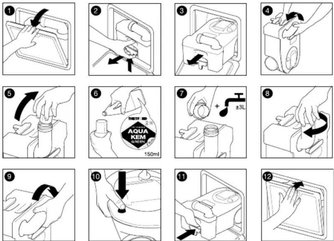
Preparing flush-water tank (only for C262-models)
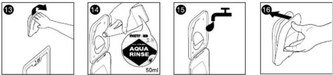
Preparing Electric Ventilator (if applicable)
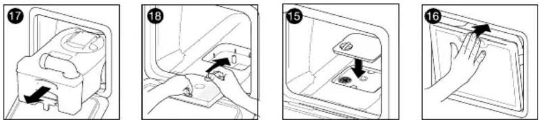
CASSETTE TOILET
Emptying waste-holding tank
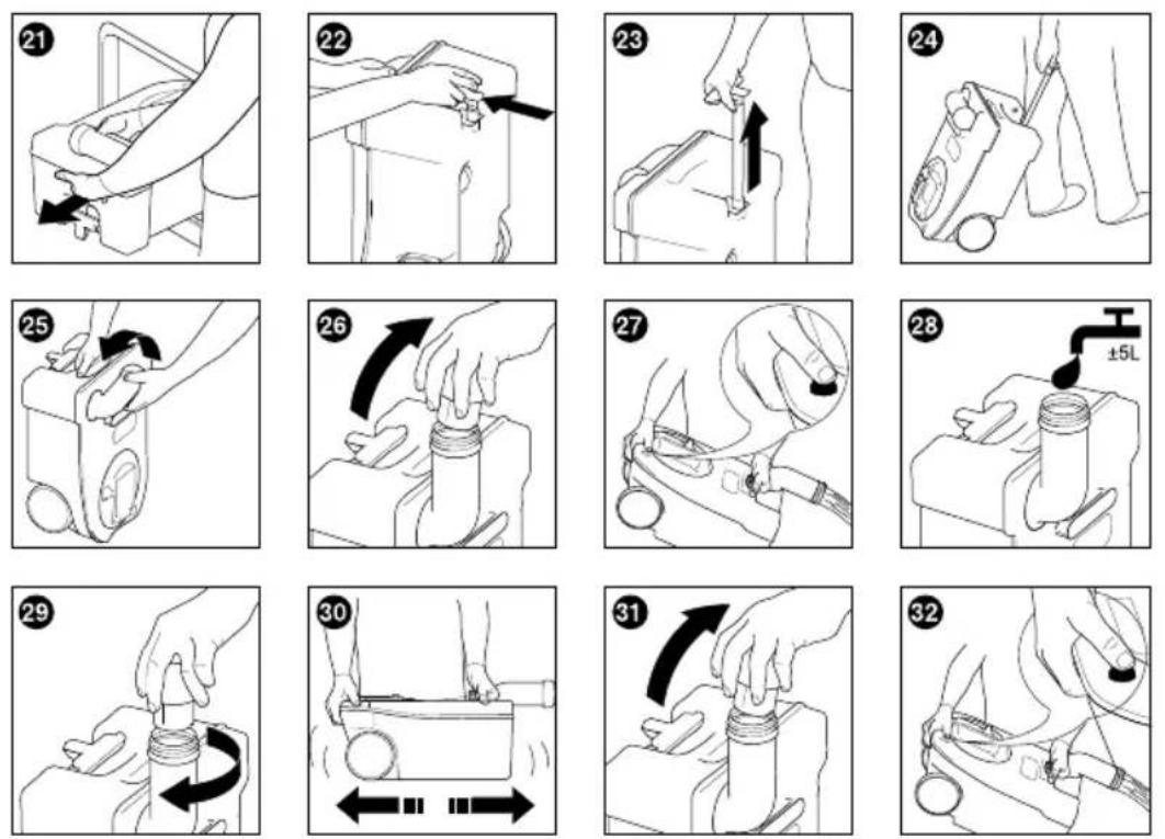
Emptying flush-water tank (only for C262-models)
natural_image
Hand pressing down on a tray with a black arrow indicating the step (no text or symbols)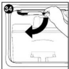
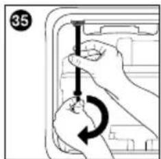
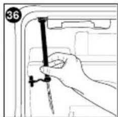
natural_image
Line drawing of a hand holding a nail, no text or symbols present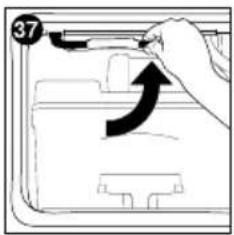
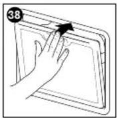
natural_image
Illustration of a hand pressing down on a tablet screen (no text or symbols visible)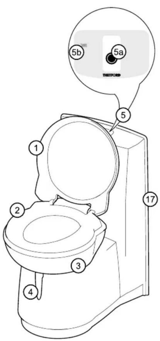
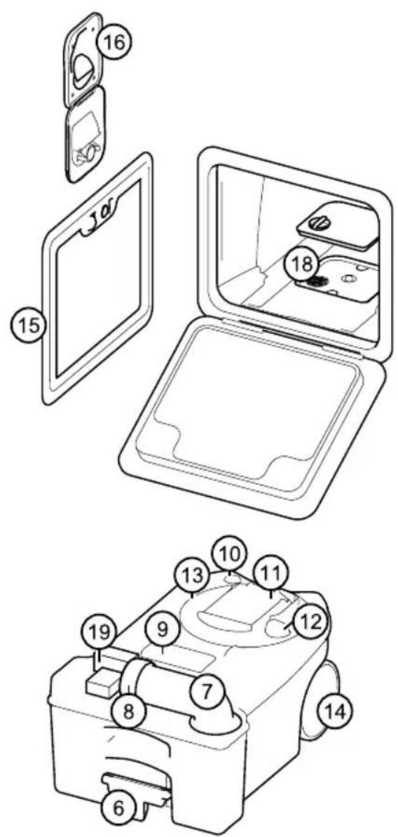
Standard
- Cover
- Seat
- Swivelling toilet bowl
- Blade handle to open/close blade
- Control panel (position is different on C263 models)
5a. Flush button
5b. Waste holding tank level indication (1 level or 3 levels; dependent on model) -
Pull handle
-
Pour out spout
- Cap with measuring cup
- Automatic pressure release vent
- Vent button
- Sliding cover
- Blade opener
- Waste holding tank mechanism
- Wheel
- Service door 3
CASSETTE TOILET
Options
- Waterfill door (only for C262 models)
- Console with flush water tank (only for C262 models)
- Filter for electric ventilator
- Location waste pump out system
Introduction
This Thetford Cassette Toilet is a high quality product. It is user-friendly, meets high quality standards and gives you all the convenience of home.
Before operating and using this toilet we advise you to read the manual completely. Keep this manual in a safe place for future reference.
For the latest version of the manual please visit www.thetford.eu
Possible toilet options
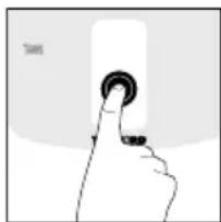
natural_image
Hand pressing a button on a white surface, no text or symbols visibleSome toilets are fitted with extra options. To check which options are available, press the flush button on the control panel.
The following symbols can light up:
- Waste pump out system - transfers waste from the waste holding tank into the vehicles's central waste tank.
- Electric blade - electrically opens or close the blade.
- Electric ventilator - draws unpleasant odours away from the waste tank to the outside of the vehicle.
You will find additional to these options in the grey text boxes. Thoroughly read the applicable instructions.
Preparing for use
This cassette toilet has a waste holding tank of 17.5L. A C262 model also has its own 8L flush water tank. Before using your toilet, it is vital that you add toilet additive to these tanks. Check the correct dosage on the additive package. Then add ±3L of water to the waste holding tank. Fill the flush water tank of a C262 model to the top.
Electric ventilator (if applicable)
Open the service door and remove the waste holding tank. Then remove the filter housing cover and place the new filter into the filter housing. Replace the cover and return the waste holding tank back to original position.
⚠ WARNING: Never add toilet additives directly via the blade as this could damage the lip seal of the waste holding tank. Only fill the waste holding tank via the pour out spout.
⚠ WARNING: Never use force if you cannot get the waste holding tank back into place easily. If blockage occurs, always check if the blade handle is in the closed position.
See Quick guide diagrams 1-20 for visual reference. To depressurise the waste holding tank, press the vent button before placing the tank back in its position.
Thetford offers a pleasantly scented toilet fluid for the flush water tank (Aqua Rinse) and a variety of waste holding tank products (Aqua Kem Blue, Aqua Kem Green, Aqua Kem Natural, Aqua Kem Sachets).
Aqua Rinse keeps the flush water fresh, ensures a smooth flush and leaves a protective layer. All products for the waste holding tank suppress unpleasant smells, stimulate the breakdown of waste, reduce the formation of gas, protect moving parts and help to the waste holding tank fresh and clean. For the differences between the distinguishing qualities of each waste holding tank product please visit www.thetford.eu
The range of available Toilet Care products may vary for each country.
Use of your toilet
Turning the bowl
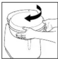
natural_image
Illustration of hands holding a bowl with a curved arrow indicating rotation (no text or symbols)You can turn this bowl to a desired position (max. ±90^ ). Close the cover and use both hands to rotate the bowl as illustrated.
Opening the blade
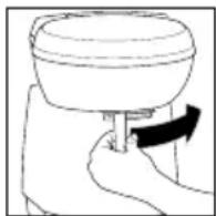
The toilet can be used with the blade open or closed. To open the blade, slide the blade sideways as illustrated. Make sure you always close the blade completely after use.
Electric blade (if applicable)
Press the flush button to activate the control panel. Then push the Electric blade button. The blade will open or close electrically.
Flushing the toilet
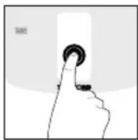
natural_image
Hand pressing a button on a white surface, no text or symbols visiblePress the flush button once to activate the control panel. Then press the flush button for several seconds to flush the toilet.
Electric ventilator (if applicable)
By activating the control panel, the Electric ventilator start automatically. The button will flash to indicate this function is active. To stop the Electric ventilator, press the button. Press the button again to restore the Electric ventilator. To optimise its function, activate the Electric ventilator before use of your toilet.
Note: Even without an own flush water tank you can still use Aqua Rinse for a smooth and fresh lavender scented flush. Simply spray Aqua Rinse with a spray can evenly into the toilet bowl before use.
Note: Ordinary toilet paper can cause clogging. Use Aqua Soft toilet paper instead. This toilet paper is super soft, dissolves quickly, prevents clogging and makes it easier to empty the waste holding tank.
Level indication
You can check whether your waste holding tank has a 1 level or a 3 level indication. Make sure the tank is empty and place it properly. Then activate the control panel. If no level indication light lights up, your toilet has a 1 level indication. It will only indicate a full tank. If a green level indication light immediately lights up, your toilet has a 3 level indication. It will indicate empty, half full and full.
Emptying the tank
Waste holding tank
When the red light of the level indicator on the control panel lights up, you need to empty the waste holding tank. Remove the tank via the service door. Then take it to an authorised waste disposal point. Empty the waste holding tank via the pour out spout.
Waste pump out system (if applicable)
By activating the control panel, this button automatically lights up. Press the button to empty the waste holding tank into the vehicle's central waste tank. The button flashes while the waste is being pumped and stops flashing when all waste has been transferred. (±1.5L of waste is left). If the central waste tank is too full (only measured when this tank has a level indicator), the button flashes rapidly and no pump out is possible until you have emptied the central waste tank.
CASSETTE TOILET
See ‘Quick guide’ diagrams 21-32 for visual reference. If you want to continue using your toilet after emptying, prepare the waste holding tank again.
Note: Our ‘green’ products Aqua Kem Green, Aqua Kem Natural and Aqua Rinse (test ISO 11734) are absolutely safe to empty into a septic tank or small biological systems on camping sites.
⚠ WARNING: Please avoid travel with a waste holding tank that is more than 3/4 full. This may cause leakage through the venting system.
Flush water tank (only for C262 models)
The flush water tank has a capacity of 8L. Only empty the flush water tank completely if you don't expect to use your toilet for a long (winter) period. Place a sufficiently large bowl under the drain tube and catch the remaining water. Empty this bowl at an authorised waste disposal point.
See ‘Quick guide’ diagrams 33-38 for visual reference.
⚠ WARNING: To prevent water damage to your caravan, ensure you don't travel with a full flush water tank or with water in the bowl.
Cleaning
Just like your toilet at home, it is also important to clean this cassette toilet regularly. You will prevent limescale and ensure optimal hygiene. Clean the inside of the bowl with toilet bowl cleaner and a soft brush and use bathroom cleaner for the outside of the toilet.
⚠ WARNING: Never use the household cleaners to clean your toilet. These may cause permanent damage to the seals and other toilet components.
Waste pump out system (if applicable)
Fill the emptied waste holding tank with water and place the tank back. Then activate the control panel. Press the waste pump out system button to pump the water through the system. Do this once every 3 weeks.
Remove seat and cover
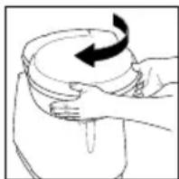
natural_image
Illustration of hands holding a container with a rotating arrow (no text or symbols)To clean your toilet thoroughly, remove the seat and cover. First push the seat and cover together to the right then lift them up.
Winter use
You can use your toilet as normal in cold weather as long as the toilet is situated in a heated location. If this is not the case, and there is a risk of frost, we advise not to use your toilet. Make sure you completely empty the waste holding tank. For a C262 model also empty the flush water tank.
Note: Aqua Kem Sachets are particularly suitable for winter camping as the sachets are filled with powder. They completely dissolve in water, are easy to dose and economical in use.
Maintenance
To prolong the life span of your toilet, maintain your toilet regularly. Use cassette tank cleaner 2 to 3 times a year on the waste holding tank.
It safely removes stubborn limescale on the inside of the tank. When seals become dry, use seal lubricant to keep the seals soft and pliable. It has been specially developed for mobile toilets and is absolutely safe to use.
⚠ WARNING: Never use Vaseline or vegetable oil to lubricate the seals as these may cause leakage to your waste holding tank.
Waste pump out system (if applicable)
To ensure optimal functionality, maintain the waste holding tank regularly. Fill the waste holding tank with water and rinse it. Then use Cassette Tank Cleaner. Do this every 6 weeks when on holiday.
Electric Ventilator (if applicable)
After approximately 4 weeks of use, the filter loses its absorption power. Remove the filter housing cover and place the new filter into the new housing.
Storage
If you don't expect to use your toilet for a long period, you have to thoroughly empty, clean and dry the whole toilet. Also empty the flush water tank of a C262 model. This is also a good moment to maintain your toilet. During storage we advise leaving the blade open to prevent damage to the blade and to loosen the cap of the pour out spout to ventilate the waste holding tank.
Electric ventilator (if applicable)
Remove the filter of the filter housing.
Disposal
Your product has been designed and manufactured with high quality material and components, which can be recycled and reused. When your toilet has reached the end of its life, dispose of the product according to the local rules. Do not use the toilet with the normal household waste. The correct disposal of your old product will help prevent potential negative consequences for the environment and human health.
Questions?
If you require further information or have any questions about your toilet, please visit our website www.thetford.eu If you still have questions, contact the Customer Service Department in your country or your holiday location.
For correct and efficient support, please ensure all relevant product type information is available.
Spare parts
Original Thetford spare parts are available through your own dealer or an authorised Thetford Service Centre.
FAQs
What should I do in case of a defect on my Thetford toilet? Contact your dealer where you bought your vehicle, or if you are on holiday, contact an authorised Thetford Service Centre.
A red light on the control panel flashes, what should I do? Check if the waste holding tank is present or positioned properly.
I cannot move my waste holding tank.
Check if the blade of your toilet is completely closed.
What should I do when the electric blade doesn't function? Manually open or close the blade by sliding the small handle under the toilet bowl sideways.
What should I do if the blade is blocked?
Loosen the cap with measuring cap from the pour out spout and try again.
Does the toilet have a fuse? Yes, the toilet has a maintenance free self-resetting fuse.
Warranty
Thetford BV offers the end users of its products a three-year guarantee. In the case of malfunction within the warranty period, Thetford will replace or repair the product at its discretion. In this case, the costs of replacement, labour costs for the replacement of defective components and/or the costs of the parts themselves will be paid by Thetford.
- To make a claim under this guarantee, the user must take the product to his dealer or an authorised Thetford Service Centre (www.thetford.eu). The claim will be assessed there.
CASSETTE TOILET
- Components replaced during repair under guarantee become the property of Thetford.
- This warranty does not prejudice current consumer protection laws.
- This warranty is not valid in the case of products that are for, or are used for, commercial purposes.
Guarantee claims falling into one of the following categories will not be accepted:
- the product has been improperly used or the instructions in the manual have been followed (for example incorrect use of additives;
• alterations have been made to the product; - the product has been repaired by an unauthorised Thetford Service Centre;
- the product code or serial ID has been changed;
-
the product has been damaged by circumstances outside the normal use of the product.
-
Not using Thetford products to care for your Thetford toilet could create some damage, which would not be covered by this warranty.
Thetford is not liable for any loss and/or damage caused directly or indirectly by use of the toilet.
Caravans with external barbeque point
Models equipped with an external barbeque point can be used to power any gas appliance suitable for the gas used in the caravan, at the working pressure shown on the label in the barbeque outlet box. Please note when using the outlet that the fitted regulator will allow a maximum of 1.5kg per hour of gas to be taken from the gas bottle. Therefore the consumption of gas from both the appliances within the caravan and the appliance connected to the barbeque point cannot exceed a total of 1.5kg per hour at any one time. If you are in any doubt please consult your dealer for advice. To use point proceed as follows:
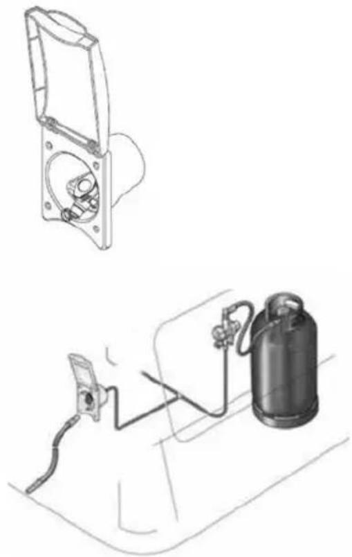
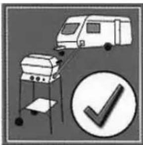
natural_image
Illustration of a van and a campfire setup with a checkmark icon (no text or symbols)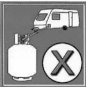
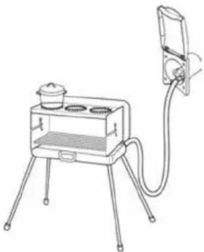
natural_image
Line drawing of a portable stove with three legs and a side-mounted unit connected to a wall-mounted device (no text or symbols)When external gas equipment is being connected, the operating pressure of the gas supply of 30 or 50 mbar must correspond with the operating pressure of he equipment that is being connected (see data plate).
The plug-in connection can only be made if the quick acting valve is closed. The safety locking mechanism can be released by sliding back the coupling sleeve.
The coupling K-valve is being designed such that the quick acting valve can only be opened if the connection is being made via the plug-in connection. The connection is made by inserting the plug-in connection into the safety coupling.
This operation can be carried out using one hand. After uncoupling the equipment, seal off the valve opening using the protection seal.
Note: The external gas socket is only suitable for removing gas, not for feeding gas into the gas system.
⚠ WARNING: Care should be taken when using the external barbeque point. Never barbeque next to an awning or tent.
⚠ WARNING: The caravan barbeque point should only be used as an outlet point for gas, never connect a gas bottle direct to the outlet.
EXTERNAL SHOWER POINT / BATTERY BOX TV INLET
External shower point
The external shower point, if fitted, will be supplied with a separate shower head and hose assembly. To connect the shower, simply align the plug with the socket and push into position. To remove, pull the lower trigger and pull the plug from the socket.
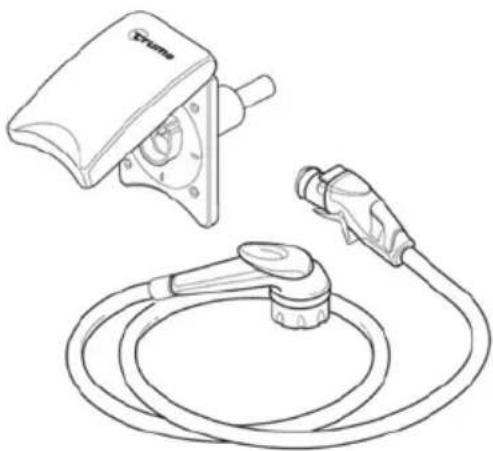
natural_image
Line drawing of a portable electric vehicle charging plug and cord (no text or symbols)Caravans with TV inlet in battery box
Models equipped with TV points in the battery box have the facility to take an external signal and supply that signal to TV points within the caravan.
Caravans equipped in this way feature a direct link from the connection point in the battery box, to an auxiliary connection point at the primary TV position within the caravan. The primary TV position is that which also features an AV outlet plate (see later text).
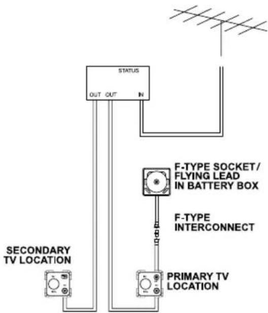
The direct link can be used to:
- Supply an external signal (caravan site TV feed) to the primary TV position
a. Connect the socket in the battery box (on flying lead depending on model), with a suitable lead, to the appropriate socket on the caravan site supply post. As the connector in the battery box is a screw on 'F-type' connector, an adaptor to convert this to a 'push-on' co-ax connector, which may be required, has been supplied with your caravan.
b. Locate the primary TV position within the caravan. At the 12V, TV and SAT socket, connect your TV to the output from the socket marked SAT with a suitable lead.
- Connect an external satellite dish to a decoder within the caravan. (The direct link uses F-type interconnects throughout to allow the decoder and dish to communicate correctly)
a. Connect the dish to the socket (or flying lead) in the battery box with a suitable lead. The F-type to co-ax adaptor should not be used.
b. Connect the dish input connection on the decoder to the 'SAT' socket on the 12V, TV and SAT socket located in the primary TV location.
- Supply a signal from within the caravan to the exterior of the caravan
a. Connect the output from your VCR, DVD player or other device to the SAT connection on the 12V, TV and SAT socket at the primary TV position.
b. Connect your receiving device (TV or similar) to the socket in the battery box with a suitable lead.
As can be seen from the simplified schematic, when multiple TV locations are present in a van, all of these receive signals from the TV aerial connection box. Using adaptors and link cables which are readily available, it may be possible to re-direct a signal from the 'SAT' connection at the primary TV location, up to the aerial connection box to be then distributed to other TV positions within the caravan. Please remember that as the number of connections increases the quality of the signal reduces.
Supplier fitted / supplied entertainment equipment
Audio-visual equipment may have been fitted by your dealer, or supplied with the caravan, depending on the specification of the caravan. Although not specific, below are details of the types of equipment which would be fitted as appropriate to the specification of the caravan:
CD/MP3/tuner with auxiliary input
Where provision has been made in the furniture to install a head unit similar in appearance to that fitted in the dashboard of a car. The unit operates as a CD player and FM/AM radio. In addition MP3 files stored on a CD can be read and played by the unit. An auxiliary input on the front of the unit allows a separate MP3 player to be connected from that player's headphone socket. (A separate lead may be required).
Speakers mounted in the front locker of the caravan are connected to this head unit for a stereo sound output. A retractable AM/FM aerial on the side of the caravan, enables reception of radio stations.
STATUS 550 DIRECTIONAL TV AND FM RADIO ANTENNA (model dependant)
Firstly determine the approximate location of the nearest transmitter and whether the signals are horizontally or vertically polarized. For assistance ask your site operator or check antennas in the vicinity
- Loosen the Mast Locking Collar and Wall Bracket and raise the antenna. Turn the mast to direct the Antenna towards the TV transmitter.
The RED spot on the bottom of the mast indicates the front of the Antenna.
- When receiving vertically polarized signals, rotate the winder anti-clockwise to cant the antenna through 90°. The red / green indicator, if present, indicates vertical or horizontal orientation.
Note: DO NOT over tighten or use undue force on the winder.
-
Switch ON the Power Pack and the RED LED will illuminate.
-
Check the gain control switch is set to normal - NML.
-
Tune your television to the strongest signal. You may need to adjust the direction of the mast to achieve the best quality picture.
-
Secure by tightening the Mast Locking Collar and Wall Bracket
Removing the antenna
A permanently fitted Status can be easily removed leaving only the Mounting Foot and rubber gaiter.
-
Unplug the antenna from the Power Pack.
-
Loosen the Mast Locking Collar and Wall Bracket and lift off whilst feeding out the cable.
-
Push the Blanking Cap supplied into place.
⚠ WARNING: The Blanking Cap is a temporary seal and is not for long term use.
⚠ WARNING: Always ensure the aerial is lowered before driving off.
BEDDING
Bedding
Sleeping bags and duvets can be compressed into small spaces and can be ready to use in minutes.
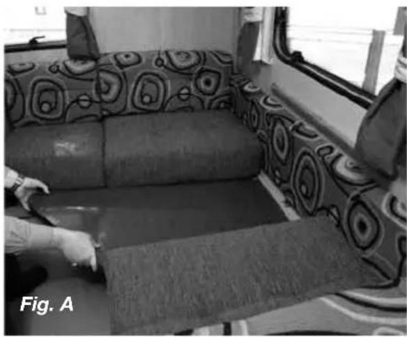
natural_image
Interior view of a vehicle cabin with patterned back cover and fabric panels, no visible text or symbols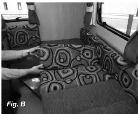
natural_image
Interior view of a train carriage with patterned bedding and a person adjusting equipment (no visible text or symbols)Lower single beds assembly (Figs. A & B)
- Lower dinette table and place between the recess in both seats.
- Arrange seat cushions as appropriate.
Double bed assembly (Fig. C)
- Grip front of slatted bed and walk backwards until bed is fully extended.
- Arrange seat cushions as appropriate.
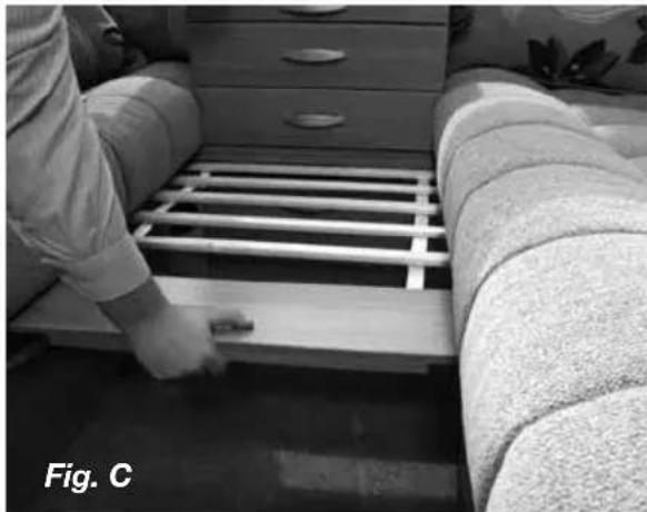
natural_image
Person installing or adjusting a grid-like structure on a bed, with no visible text or symbolsLift-up bunks
- Grasp the bunk and pull carefully upwards and towards you. (Fig. D)
- The bunk is designed to automatically move into the correct position. (Fig. E)
- Where a bed board is fitted, unfold and make sure it is secured by press studs when lifted into position. (The bed board is required to protect both the occupant and the window from damage during use of the bunk.) (Fig. F)
- Locate safety boards. (Fig. G)
- Arrange seat cushions as appropriate. (Fig. G)
Bunks are designed to carry a child to a maximum of 70kg (11 stone)
⚠ WARNING: use the upper bunks for sleeping only, with the provided protection against fall out in position.
⚠ WARNING: Care shall be taken against the risk of fall out when the upper bunks are in use by children especially under 6 years of age, these bunks are not suitable for use by infants without supervision.
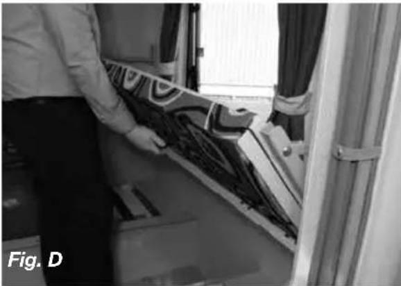
natural_image
Person installing or adjusting a patterned fabric on a window, no visible text or symbols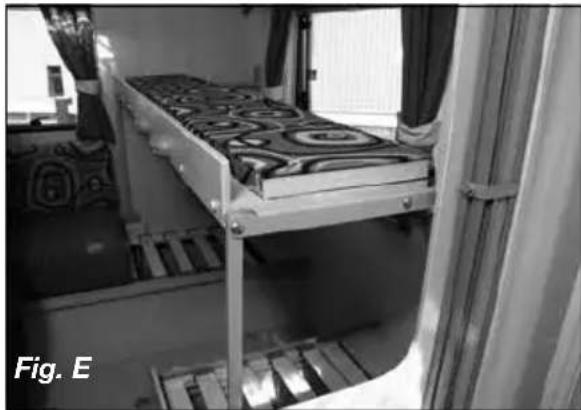
natural_image
Interior view of a train carriage with a metal bunk bed and adjacent window (no visible text or symbols)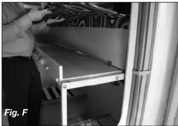
natural_image
Person assembling a metal shelf in a kitchen or storage room (no visible text or symbols)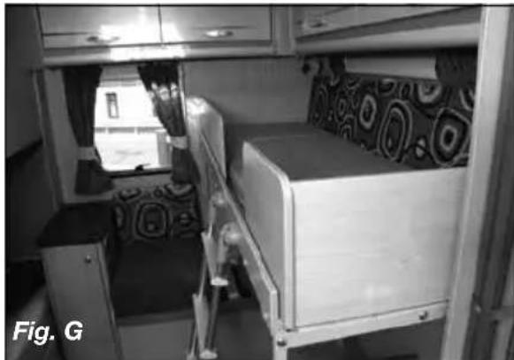
natural_image
Interior view of a train carriage with two beds and a window, no visible text or symbolsOperating instructions for softrollo blinds
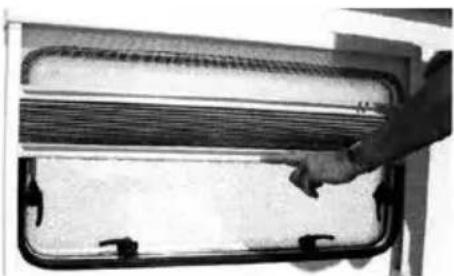
natural_image
Close-up of a hand opening a rectangular device with a mesh grille (no visible text or symbols)Hold the operating aluminium bar in the middle and raise or lower the blind and flyscreen independently, operating together will require excessive force in operation.
Care instructions: Clean the blind only with a damp sponge. Clean on a regular basis to avoid dirt particle build up as this can damage the blind material.
Use only water or with mild suds or a vacuum cleaner.
In order to avoid material fatigue, do not leave the flynet closed for a long time.
Maintenance
If operation of the soft Rollo blind is exceptionally stiff, it is possible to spray the guide - legs (left and right) with a Teflon - spray. This will ease both the operation of the blind and avoid any interruption/malfunction from deposits in the guide legs which may affect the operation.
Doorscreen
When drawing or releasing the doorscreen, care should be taken not to let it spring back freely, this may result in damage to the screen or its fittings.
BLINDS / ROOFLIGHT / CONQUEROR EXTERIOR DOOR
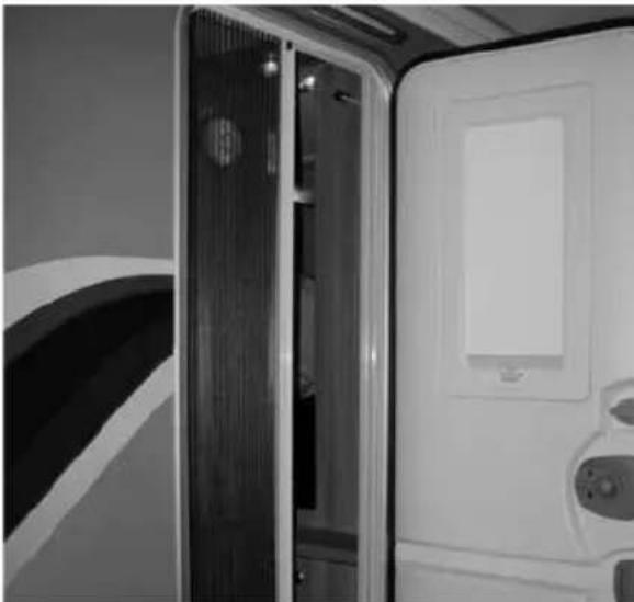
natural_image
Interior view of a modern vehicle or cabin with a closed door, ventilation ducts, and control panel (no visible text or symbols)Always pull the doorscreen close to the centre. It is not advisable to pull close to the top or bottom as this will cause snagging and uneven running.
⚠ WARNING: When opening or releasing the doorscreen, care must be taken to avoid trapping fingers. When opening or releasing the doorscreen, care must be taken to avoid trapping fingers.
The door flynet operates independently of the door by sliding across the door threshold.
Roof lights
When opening the roof lights, care must be taken to release the locking mechanism as the unit is raised.
Roof lights must be fully closed when towing.
Roof lights provide varying levels of fixed ventilation.
Exterior Door Key
⚠ WARNING: Care should be taken not to leave the exterior door key in the door when unlocking the door. The key may result in damage in the vehicle side if the door is released with the key still in the lock.
Exterior Door Operating Instructions- Conqueror
To un-lock the door, insert the key and turn clockwise ensuring the key is removed before the door is opened to prevent damage to the caravan side.
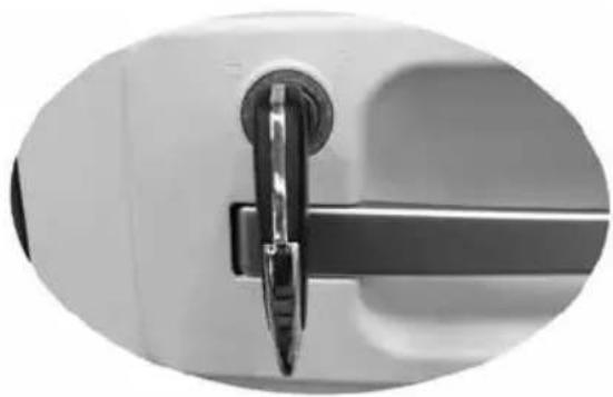
natural_image
Close-up of a metallic door handle with a metallic clip, no visible text or symbolsThere are 3 primary positions for the internal handle inside the caravan, these are locked, neutral and open. When closing the door from the inside the caravan ensure the handle is in the neutral position, The handle MUST NOT be partially up in the locked position as this will prevent the door from closing causing damage to the door
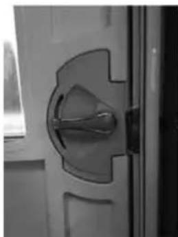
natural_image
Close-up of a door handle with a metallic key inserted, showing metal framing and curved glass panels (no text or symbols visible)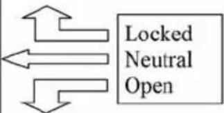
flowchart
graph TD
    A["Left Arrow"] --> B["Locked"]
    C["Right Arrow"] --> B
    D["Down Arrow"] --> B
    B --> E["Neutral Open"]
The door flyscreen is tracked top and bottom and operation must be by the centre of the handle to aide a smooth operation.
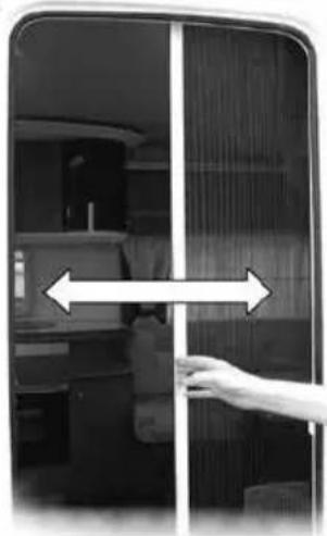
natural_image
Interior view of a modern kitchen or dining area with a hand adjusting the door (no visible text or symbols)The door blind slides vertically within the door cassette.
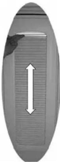
natural_image
Close-up of a metallic oval object with a double-headed arrow indicating vertical compression (no text or symbols)Windows
To open all window types turn the internal handles through 90 degrees and push open the window.
On models fitted with telescopic stays:
push open the window to the desired position and tighten the stay. To close the window, loosen the stays and slowly close taking care to fold the stay inside the window and lock off the handles by turning back through 90 degrees.
On models fitted with ratchet stays: the window locks in the open position to pre-set positions located within the stay. To operate, push open the window until you hear an audible click and then slowly release the pane and the window will be locked in the first open position. Push open again to find the next locking position. To close, fully open the window which will disengage the locks and allow the window to close slowly and lock off the handles by turning back through 90 degrees.
Windows / Roller Blind Advice
In case of prolonged exposure to the sun roller blinds should not be completely closed as this could cause excessive heat concentration at the top of the window, due to characteristics of the glazing material the windows could be adversely affected.
Roller blinds that shade from the bottom upwards it is necessary to leave a gap of a few centimetres open at the top, this way the heat between window and blind can escape. A fly screen does not cause an obstruction.
Roller blinds that shade from the top downwards must be kept completely open, or be opened regularly to allow the heat to escape.
Keeping the windows in ventilation position allows heat to escape.
Never fully close a roller blind system when storing the vehicle or when not in use for longer periods!
Therefore for optimal window life it is recommended:-
- Blinds starting at the bottom of the window a gap should be provided for ventilation at the top with the window in its ventilation position.
- For vehicles containing blinds from the top downwards or with other types of reflective blinds / curtains, please make sure that these blinds are also ventilated or not fully closed.
Ensure that all windows and roof vents are closed when the vehicle travels on the road.
Mini Heki rooflight
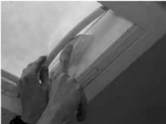
natural_image
Close-up of hands installing or adjusting a ceiling panel (no visible text or symbols)To open depress the button (Fig. A).
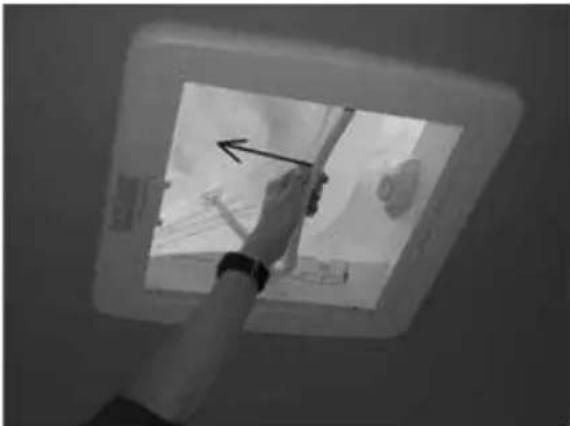
natural_image
Hand pointing at a small object inside a square ceiling light fixture (no visible text or symbols)Pull the bar down and forwards (Fig. B).
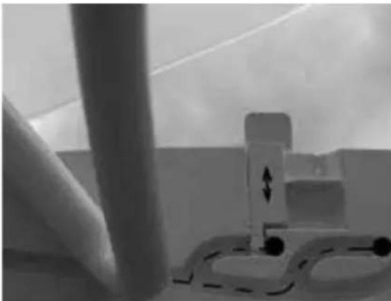
natural_image
Interior view of a room with a cylindrical pipe and two small white fixtures, no visible text or symbolsBy pushing the bar in to the marked rest positions (Fig. C).
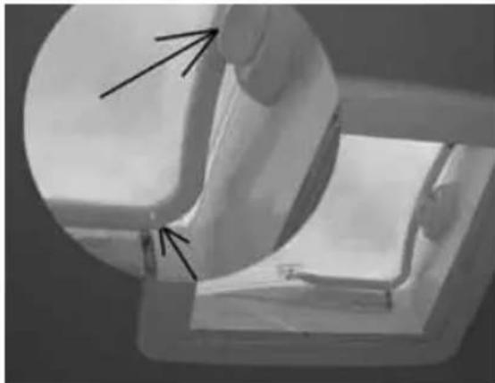
natural_image
Close-up of a hand holding a small object, possibly a container or mechanical part, with no visible text or symbols.Two extra opening angles apart from the one in which the dome is fully opened can be chosen. The intermediate position can be fixed with a slide marked with the arrows. Care should be taken to ensure the dome is closed and locked for transit with the bar located behind the locking button (Fig. D).
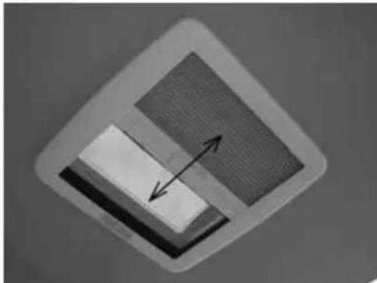
natural_image
Diagram showing two rectangular panels with directional arrows, no text or symbols presentThe blind flynet operate together and engage via the clips in the bar, then slide to gain the desired blackout or ventilation (Fig. E).
Heki care instructions
Clean the blind only with a damp sponge. Clean on a regular basis to avoid dust/ dirt particle build up as this can damage the blind material. Use only water or with mild suds or a vacuum cleaner.
In order to avoid material fatigue, do not leave the flynet closed for a long time.
Midi-Heki rooflight
Opening the Dome
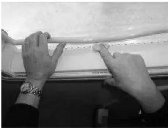
natural_image
Close-up of hands installing or adjusting a white plastic sheet on a surface (no visible text or symbols)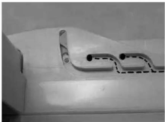
natural_image
Close-up of a white plastic surface with a dashed curved line and two black dots, no visible text or symbols.Closing the Dome
(drive and rest position)
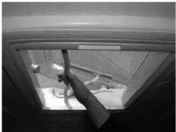
natural_image
Black-and-white fisheye view of a vehicle's window with visible structural components and a hand interacting with the door (no text or symbols)Push the bar with both hands on the right and the left side in such a way that the hook bolt (1) the dome on the left and the right side and the bar lies on the push button (2). Check if the dome is locked.
natural_image
Close-up of a pipe being inserted into a white plastic sheet (no text or symbols visible)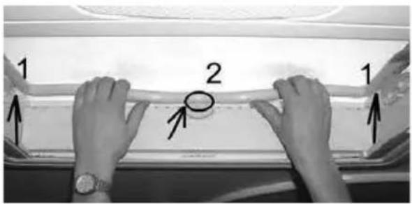
1
natural_image
Close-up of a small transparent bottle partially submerged in liquid, placed on a white surface (no text or symbols visible)2
natural_image
Close-up of a circular metallic object with textured surface and two small bowls on a white surface (no text or symbols visible)Intermediate position for the dome
By pushing the bar into the marked rest position, two extra opening angles, apart from the one in which the dome is fully opened, can be chosen.
HEKI ROOFLIGHTS / FURNITURE CARE
Safety precautions:
- Repairs should be carried out only by trained personnel.
- Inform an approved dealer in case of defects and malfunctions.
- Before starting off, check the rooflight for damage in the dome (tension cracks) and the opening mechanism which could arise owing to, for example, branches and other natural causes.
- Do not step on the dome.
- Close the rooflight before starting off (check whether it is locked).
- Do not leave the vehicle with the rooflight open (danger of burglary).
- Do not open in strong wind or rain.
- Before opening the dome remove snow, ice, dirt etc. from the dome.
- Malfunctions are to be repaired by an approved dealer at once.
- Do not use caustic detergents (danger of tension cracks in the dome).
- Before setting off close the dome, check the locking mechanism and open the blinds.
Care instructions:
- Clean the dome with the Seitz Acrylic Cleaner.
- Opaque spots and light scratches on the dome can be removed with the Seitz Acrylic Polish and the Seitz Special Polishing cloth.
- Use talcum powder regularly (4 times yearly) to care for the rubber seals supplied with versions without permanent ventilation.
- Clean the blinds only with water and mild soap suds.
The guarantee becomes null and void if the care and safety instructions are not followed.
Care of laminate tops, tables, furniture and doors
Do not use abrasives, chemically treated cloths or aggressive detergents as these may cause damage
Do not place hot objects on laminated surfaces i.e. tops, tables. Any temperatures 70^ C and over may cause permanent damage.
Clean worktop surfaces, furniture and door fascias with a soft, slightly damp cloth, dry off with a soft cloth.
Doors
In order to provide customers with the latest designs of door furniture it is possible, due to the use of natural wood, that warping may occur. This should not detract from the correct functioning of items fitted in the caravan.
Information
During the normal travelling vehicle vibration and flexing may cause some of the furniture doors to become out of alignment.
For your convenience many hinges are adjustable.
TABLES / 12V READING LAMP / SHOWER USE
Tables
Slide the top of the chest of drawers forward to form a convenient table. Lift the rear portion to slide the top away. (Fig. A)
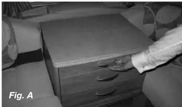
natural_image
Black-and-white photo of a person handling a wooden drawer with drawers, no visible text or symbols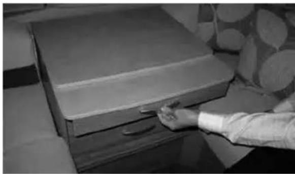
natural_image
Person opening a wooden drawer with a handle, placed indoors near a patterned bed (no visible text or symbols)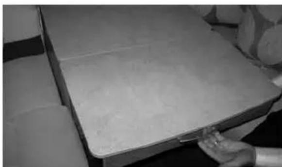
natural_image
Close-up of a white rectangular object with a flat surface, possibly a container or tray, being handled by hands (no visible text or symbols)⚠ WARNING: When erecting the free standing table, be careful to avoid trapping fingers.
Table storage
To avoid damage care must be taken when removing tables from their stored position.
Where two tables are stored together in a low level storage area care should be taken to remove the table positioned opposite the hinged edge first.
Tables stored in the table storage compartment must be securely clipped into place whilst in transit.
12V reading lamp
⚠ WARNING: 12v tungsten reading/ spotlamps generate high temperatures when in use, the body, lens/ bulb may become very hot. NEVER make directional adjustment in the direction of flammable materials i.e. curtains, nets or blinds.
Shower use
- Care should be taken as water may become hot temporarily when switched on until it mixes and regulates.
- Small children should be surprised at all times when using the shower.
- We recommend unfastening the shower head before travelling and storing safely to prevent it becoming detached whilst towing.
Fixing of awnings
In order to avoid puncturing the outer skin of the caravan wall, it is recommended that awning poles are fixed to your caravan using load spreading eyelet pads or rubber sucker pads.
Attaching awning brackets and associated fixings to your caravan by using mechanical methods which pierce the outer skin of the caravan wall can allow water ingress which will invalidate the product warranty.
Important:
Care must be taken when using an awning as poles and suckers can cause damage to exterior side panels.
Awnings should be taken down in strong winds to protect the side panels from cosmetic damage and dents from the awning poles.
Note: Awnings should be kept ventilated when discharging products of combustion exhaust into them.
Awning Sizes
Due to the various awning types and sizes the awning sizes provided in the Service and Warranty Handbook are for guidance only.
Full details and sizes of awnings (A-A dimensions) for your caravan can be found in your Technical Handbook.
Specific awning sizes must be confirmed with the dealer or awning manufacturer prior to purchase.
Colour reference
If you require touch-up paint or a respray of your caravan, the correct colour code for all white components is Fiat White 249.
Please be aware that colours can fade over time, and therefore, if the vehicle is more than a few years old, it is suggested a colour match be obtained.
Drop down TV mechanism
In some models, a drop down TV mechanism is used. Customers are reminded to engage both positive locks, on the underside of the TV mechanism before travelling. Failure to do so may result in damage of the TV unit or the TV shelf itself.
The inner dimensions (i.e. maximum TV size) for this unit is 336mm high x 390mm wide x 70mm deep
Front locker and sunroof
The front locker is made from ABS thermoformed plastics, which are easy clean textured surfaces. To ensure long life and prevent damage you must not use any cleaning materials including solvents or aggressive cleaning materials. We recommend the use of warm soapy water, applied with a damp cloth.
Where a front sunroof is fitted, directly above the front windows, it is recommended that the blind be left open during use (or storage) in high temperatures or direct sunlight, to avoid a build-up of heat within this non-opening window.
Bonded Roof
The roof of your caravan is made from a bonded construction. Care should be taken when cleaning the roof not to walk directly on the roof. If access to the roof is required the weight of a person should be spread across a larger area using a spreader board and extreme care should be taken when working at heights.
Step on hitch cover
Where a step on hitch cover is fitted, customers are reminded only to stand on the designated areas, identified with black anti-slip matting. Stepping elsewhere on the hitch cover may result in damage to the hitch cover.
Models without a step on hitch cover are not suitable for standing on and failure to follow these simple instructions may result in premature failure or cracking which will not be covered by any guarantees (including extended warranties).
Cycle racks
The Swift Group allows the fitment of a two cycle rack to our caravans and we have made provision for fixing blocks on most models for this purpose.
Due to the complex nature of a cycle rack, the different models available and the need to break into the habitation box (therefore, having a potential of a leak), we suggest this modification only be carried out by a competent person, ideally, a Swift Group dealer or Authorised Repairer.
Please be aware a cycle rack can not be fitted onto a model where there is a rear escape window. Please confirm this with your Swift Group Dealer.
Caravan motor movers
The design and fitment of a caravan motor mover shall be in accordance with the NCC Code of Practice 305 and you should ensure you receive a signed installation certificate of compliance from the installer.
Failure to do so may invalidate your warranty
OMNIVENT
Omni-vent
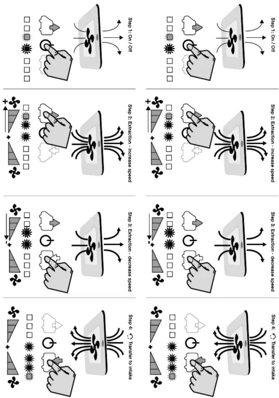
Use rooflight
- Close the lid before driving
• To take away the roller blind, unscrew and click the frame off the side of the knob.
Use of the ventilation
- The ventilator is started by the soft switch S2. The middle LED light lights up and the ventilator starts in comfort mode, this is the lowest speed (extract). See fig 18.
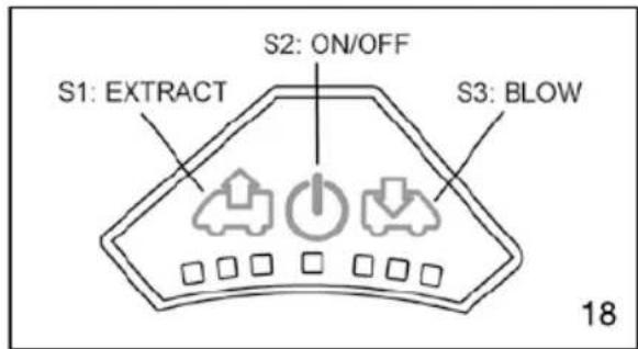
- By pushing on the switch S1 (extract) or S3 (intake), the airflow can be adjusted in 6 steps. See table 19.
| PUSH BUTTOMS | LIGHTS | SPEED | Ampère | Watt |
| ■ ■ ■ ■ ■ ■ ■ | 0 | 0,2 mA | 2,4 mW | |
| 1x ⏻ | ■ ■ ⬇ ⬇ ⬇ | 1 ♂ | 0,17 A | 2 W |
| 1x ⏻ + 1x ⭕ | ■ ■ ⬇ ⬇ ⬇ | 2 ♂ | 0,40 A | 5 W |
| 1x ⏻ + 2x ⭕ | ■ ⬇ ⬇ ⬇ ⬇ | 3 ♂ | 0,90 A | 11 W |
| 1x ⏻ + 3x ⭕ | ■ ⬇ ⬇ ⬇ ⬇ | 4 ♂ | 1,55 A | 20 W |
| 1x ⏻ + 4x ⭕ | ⊕ ⬇ ⬇ ⬇ ⬇ | 5 ♂ | 3,20 A | 40 W |
| 1x ⏻ + 5x ⭕ | ⊕ ⬇ ⬇ ⬇ ⬇ | 6 ♂ | 7,20 A | 86 W |
| 1x ⏻ + 5x ⭕ + 1x ⭕ | ⊕ ⬇ ⬇ ⬇ ⬇ | 5 ♂ | ||
| 1x ⏻ + 5x ⭕ + 2x ⭕ | ■ ⬇ ⬇ ⬇ ⬇ | 4 ♂ | ||
| ... ... ... | ||||
| 1x ⏻ | ■ ■ ■ ■ ■ ■ ■ | 0 | 0,2 mA | 2,4 mW |
| PUSH BUTTOMS | LIGHTS | SPEED | Ampere | Watt |
| ■ ■ ■ ■ ■ ■ ■ ■ | 0 | 0.2 mA | 2.4 mW | |
| 1x ⏻ | ■ ■ ⊕ ✉ ■ ■ ■ | 1Ω | 0.17 A | 2 W |
| 1x ⏻ + 1x ⏻ | ■ ■ ■ ✉ ■ ■ ■ | 0 | 15 mA | 0.2 W |
| 1x ⏻ + 2x ⏻ | ■ ■ ■ ✉ ⊕ ■ ■ | 1Ω | 0.17 A | 2 W |
| 1x ⏻ + 3x ⏻ | ■ ■ ■ ✉ ⊕ ■ ■ | 2Ω | 0.40 A | 5 W |
| 1x ⏻ + 4x ⏻ | ■ ■ ■ ✉ ⊕ ■ | 3Ω | 0.90 A | 11 W |
| ... ... ... |
$$ ^ {*} \mathrm{MIN} = 3, 7 \mathrm{m} ^ {3} / \min (2 \mathrm{W} - 0, 1 7 \mathrm{A}) $$
$$ ^ {*} \text { MAX } = 2 4 \mathrm{m} ^ {3} / \min (8 6 \mathrm{W} - 7, 2 0 \mathrm{A}) $$
- In order to save the battery, the speed drops from position 6 to the lowest position after one hour of use.
- It is possible to allow the ventilator to work for 5 minutes on the highest speed (boost). To do this push for 3 seconds on the button
S1 (extraction) or S2 (intake). After 5 minutes the ventilator returns to its previous speed setting. See table in fig 20.
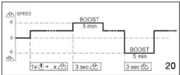
line
| Time | Speed (SPEED) | | :--- | :--- | | 0-1x | 0 | | 1x+...x | 2 | | 3 sec | 4 | | 5 min | 6 | | 3 sec | 4 | | 5 min | 2 | 20- For reasons of security, the ventilator, the ventilator stops when the tension is too high (19,5 V) or too low (11,1 V) or when the fan is blocked. For trouble shooting see fig 21.
| FLASHING LED's | PROBLEM |
| or Tension < 11,1 Vor Tension > 19,5V | |
| Motor blocked | |
| Motor not connected |
Maintenance
The ventilator grid can be removed for cleaning. Also the mosquito screen can be taken out for cleaning.
Remark on the transport of the caravan with Omni-vent
The roof light is only waterproof in the direction of the traffic. When transporting the caravan in the opposite direction, or when the back of the caravan is up, ensure the dome is watertight by using the 'Lock-unlock' (not supplied on a ventilator version) or by using something that ensures that the dome remains closed when being transported.
TOURER REAR VIEW CAMERA
Tourer Rear Vision System
When fitted, a rear vision camera will be present close to the high level brake light at the rear of the caravan, connected to a wireless transmitter housed above the number plate recess.
natural_image
Close-up of a metallic electrical outlet with a circular socket and a rectangular base (no text or symbols visible)Fig. 1 Rear camera pod
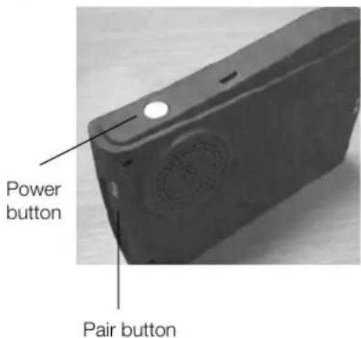
Fig. 2 Rear vision screen
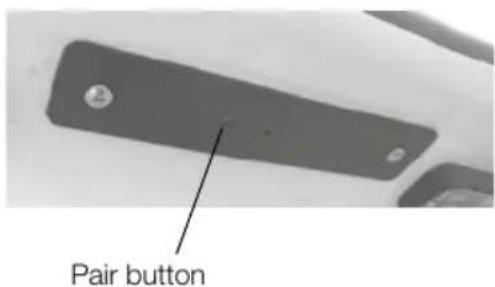
Fig. 3 Rear view transmitter
Supplied separately, a screen with power supply leads, and a windscreen mount, is to be used in the towing vehicle to receive pictures from the transmitter. The screen has an internal re-chargeable battery, allowing short term use without a power supply lead. For longer journeys, or to re-charge the internal battery, please use the power leads provided.
The camera and transmitter will be operational when the towing vehicle is connected (via the 13-pin towing lead), and the tow vehicle engine is running. When the screen is then turned on, via an extended press of the power button on the top of the unit, images from the camera / transmitter will automatically be displayed. Press and hold the power button again to switch the screen off.
If an image is not displayed, please check the following:
- The screen has two input channels. While the screen is ON, short presses of the power button will alternate the display between these channels. Check the alternate channel for an image.
- The transmitter and receiver need to be paired, to communicate with each other. This should have been done by the supplying dealer, but if the settings have been lost please repeat the procedure described below.
Pairing the transmitter and screen
- Ensure that the screen has sufficient charge for use without a power lead.
- Connect the tow vehicle and start the engine. Ensure you have an assistant with you who can stay in the car while the engine is running, for both safety and security reasons.
- On the screen, find the recessed pairing button as shown in the image on this page. (Fig. 2)
- At the rear of the caravan, locate the rectangular plate housed between the number plate lights, and find the pairing button as shown in the image on this page. (Fig. 3)
-
Turn the screen on. Using a small diameter item such as a paper clip, press the pair button on the screen unit. A message 'PAIRING START' or similar will be displayed. (Fig. 2)
-
Using a small screwdriver, press the pairing button on the rectangular plate between the number plate lights. (Fig. 3)
- Once pairing is complete, an image will be displayed on the screen.
MAINTENANCE
Vehicle modification and non-standard parts 196
Caravan movers 196
Caravan exterior 196
Caravan interior 198
Winterisation/storage 202
AL-KO chassis 205
AL-KO ATC control system.... 205
Axle types 210
Operating instructions for AKS 3004 216
Chassis trouble shooting 225
Chassis accessories 227
Vehicle modifications & non-standard parts
As the owner of a Swift Group Product, you are able to make any modifications you wish, either by yourself or through a dealer, without affecting the Swift 3/6/10 Year Warranty.
However, please be aware that any issues, resulting directly or indirectly, from a modification or fitment of a non-standard part, will not be covered by The Swift Group Warranty.
WD40 is not recommended for external or internal use
WD40 attacks paintwork and sealants.
If a lubricant is required for Interior hinges, Sliding door tracks, Bottle box hinges, Exterior door hinges, Plastic tracking etc. We recommend “Ambersil 40+” this is readily available from most DIY/ Automotive spare part retailers
Before carrying out any DIY work within the warranty period (3/6/10) years please check with your Swift Group dealer.
Caravan movers
If thinking of installing a caravan mover as an after fit it is advisable to consult your dealer, as this may not be possible with shock absorbers (if fitted).
Caravan exterior
Aluminium Panels
The stove enamelled paintwork is very durable and easy to clean owing to the high gloss properties.
Plastic Panels (GRP/ABS)
These are used for front and rear panels and, in some cases for the roof.
Cleaning
For both aluminium panels and plastic panels.
- Wash the caravan regularly with mild detergent. Rinse with cold water and leather off.
- For better protection a similar coloured good quality car wax may be applied.
For sealed areas a mild soap is the best way to clean without affecting the sealant.
Acid or alkaline based cleaners or solvents should not be used.
⚠ WARNING: Under no circumstances use any abrasive cleaning agents or solvents on the exterior panels.
Care should be taken as the silicon in some polishes can attack the rubber used on the exterior for seals and gaskets.
Acrylic Windows
Wash windows carefully, as you would with the paintwork of your car, do not scrub windows prior to removing surface dirt and film with a hose pipe - trapped dirt could cause scratching.
Wash with a solution of warm soapy water, windows can then be dried off with a leather.
Small scratches can be removed, consult your dealer.
Catches and stays do not require any special attention or lubrication.
Acrylic (Plastic) Window Condensation
Unlike domestic double glazed windows, your caravan window are not vacuum sealed instead the double panes of acrylic plastic with are fitted with a breathable plug on the inner pane.
It is possible, in weather where extremes in temperatures occur between night and day, that customer will notice condensation between the panes. The same phenomenon may also occur when washing your vehicle on a hot day.
The condensation should clear itself when the ambient conditions return to normal and
the air between the panes dries. However, if this is taking a longer time than required, the breathable plug (normally located in the top corner of the window) can be removed, with a pin or sharp object, and replaced when the panes are dry. Care should be taken when doing this.
Acrylic (Plastic) Window Cleaning
The material used to produce most caravan and Motorhome windows is acrylic plastic. While the acrylic used is very durable, it is able to be scratched with relative ease and therefore, care must be taken when clearing your vehicle not to use aggressive clearing products. Equally, care should be taken when using a drying cloth that it is clean and free from grit.
Condensation
What is condensation
Condensation is the process of change of water from its gaseous form (water vapour) into liquid water when it comes into contact with a surface that is cold. Condensation generally occurs when warm air cools quickly and looses its capacity to hold water vapour, and as a result water vapour condenses to form droplets.
Why condensation occurs
Condensation occurs when warm moist air meets a cold surface. The level of condensation will depend upon humidity levels, how moist the air is and how cold the surfaces are they come into contact with.
If the temperature falls below the dew point temperature, it is quite normal for condensation to occur on any material within the caravan that is cold, for example the external walls, plastic windows etc.
When condensation occurs
Condensation occurs usually in winter months, because ambient temperatures are colder (leading to cold surfaces) and windows and roof vents are opened less so the moist air cannot escape.
Where condensation occurs
Condensation will occur where warm moist air is put into the atmosphere in areas such as in bathrooms (during showering) and in kitchen areas (during cooking).
In the enclosed space of a caravan, the moist air from the kitchen or bathroom areas will inevitably transfer to the rest of the vehicle, which in turn condenses on cold surfaces leading to visible water droplets. This issue is compounded by warm moist air being generated from normal breathing.
Condensation will also form in cold areas where air movement and ventilation is restricted (e.g. cupuboards, wardrobes, under beds, etc.)
What is important
It is important to provide ventilation and air flow, so that warm moist air can escape, or be externally cooled, and to use the heating reasonably by not making the caravan too warm such that people perspire, as this will only serve to generate more moist air and therefore more condensation.
However, in particularly cold periods, where the external ambient temperatures are low, condensation may still form on external walls as the insulation levels may well not be thermally able to cope with the difference between the internal and external temperatures.
How can you prevent condensation
Provide ventilation so that moist air can escape.
a. Good ventilation of the vehicle when cooking or when drying clothes, footwear or pets is essential. Observe when windows begin to show signs of misting and increase ventilation by opening slightly by 1cm or opening a roof vent, as these will help, but keep the habitation door closed as much as possible to retain heat.
b. If drying damp clothes or towels, open a window to ventilate the area and allow the moist air to escape.
EXTERIOR AND INTERIOR MAINTENANCE
c. Try to make sure that the caravan is partially heated. It can take a long time for a cold caravan to warm up, so it is better to have a small amount of heat for a long period then a lot of heat for a short time.
d. After showering, keep the bathroom window or skylights open, and shut the bathroom door long enough to dry off the room.
e. Fixed ventilation is provided in the vehicle, specifically through the floor, it is important not to block these.
f. Electrical heating is dryer than gas heating, and introduces less moisture into the atmosphere. Do not use additional portable paraffin or flue-less gas heaters at all.
g. If left unoccupied and unheated for long periods of time the temperatures can soak down thermally into the entire product and become very cold. Whenever possible, put the heating on at a low level before use by pre heating in cold weather.
h. Even with reasonable ventilation it is likely if the temperature is less than 5^ C and the humidity is high that condensation will occur. Ideally the temperature should be kept about 20^ C when occupied.
Mould Growth
Any sign of mould growth is an indication of the presence of moisture and if caused by condensation gives warning that heating or ventilation may require improving.
New vehicles
New products take a long time before they are fully 'dried out' because of the moisture in the materials used during manufacture. While this is happening extra heat and ventilation will be required.
⚠ WARNING: Do not wash your caravan with a high pressure washer as these can permanently damage the seals of your caravan.
Corrosion
Your caravan has been designed and built using the corrosion resistant materials (e.g. aluminium panels, stainless steel fixings, hot dip galvanised chassis and powder coated extrusions), which if looked after will extend the life and aesthetics of the product in normal service. In certain conditions, for example, if sited for extended periods in close proximity to sea and sand spray, you may experience premature ageing and/or corrosion of the vehicle than under normal conditions.
To help prevent this, we advise regular cleaning and application of a good quality external car polish. For extended periods (where the vehicle is not in use), we recommend the use of well fitted breathable vehicle cover as protection from harsh coastal elements.
Changing Exterior Bulbs
ALWAYS REPLACE LIKE FOR LIKE.
For individual replacement bulb specification, refer to your Service Handbook.
Bulb Replacement and Type
Full details of the bulbs used with your Swift Group product can be found in your Technical Handbook. Details of how to change the various bulbs can be found within our Practical Guides, located on Swift Talk (http://www.swift-talk.co.uk/forum/topics/swift-group-practical-manuals)/
Caravan interior
Follow these guidelines to ensure your investment is receiving the very best attention.
Side Walls, Roof Lining
A simple wipe over with a damp cloth and a very mild detergent is all that is needed.
Soft Furnishings
Should be vacuumed occasionally to remove grit and sand and help to keep its smart appearance and ensure long life. The upholstery can be cleaned with a mild, reputable upholstery cleaner. It is recommended that the curtains and pelmets are specialist cleaned only. The foam used
in cushions is manufactured to meet fire regulations. It requires time to return to its normal position after prolonged use.
Impala Fabric (model specific)
The Impala fabric fitted to some Swift Group products is a luxury stain resistant durable fabric.
In most cases, wet wipes are enough to clean a stain from the fabric, however, for certain stains stronger solutions are required.
Care Instructions
General dirt and stains
- Firstly, excess liquid should be blotted with an absorbent paper or cloth so as to remove most of the liquid from the surface. After this, rub the fabric gently with a white paper or white cloth to absorb the remaining dampness.
- The easiest way to clean is using a wet wipe or using a clean white cloth dampened with plain water. Gently rub the area of stain using small circular motions. Do not soak the fabric in the solution as excessive soaking can cause damage. More persistent stains may need a solution of 95% water and roughly 5% soap (a gentle washing up liquid is recommended).
- Allow the cleaned area to dry completely and then gently brush or vacuum with a soft brush the area that was cleaned using strokes in the direction of the pile of the fabric.
- More persistent stains may need a second treatment after allowing the fabric to dry. Stains of ballpoint pen, grease etc may not come out easily using the above treatment and cleaning with a diluted solution of ISOPROPYL ALCOHOL (sometimes known as “rubbing alcohol” available from pharmacies) using a white cloth will then usually help.
IMPALA FABRIC
Cleaning Solutions
Please refer to the table below for the best cleaning solutions for different types of stains:
| Staining agent Clean water 95% water / 5% washing up liquid | Diluted IPA Alcohol | Wet wipes | |
| Black ink | ● | ● | |
| Blue ink | ● | ||
| Marker pen | ● | ||
| Coffee | ● | ||
| Tea | |||
| Red wine | |||
| Soft drinks | ●●●● | ||
| Milk | ●●●● | ||
| Ketchup | ● | ||
| Mustard | ● | ||
| Steak sauce | ● | ||
| Soy sauce | |||
| Mayonnaise | ●●●● | ||
| Butter | |||
| Salad oil | |||
| Chocolate | |||
| Make-up | ● | ||
| Face cream | ●●●● | ||
| Suntan Oil | ●●● | ||
| Suntan Lotion | |||
| Lipstick | ● | ||
| Urine | |||
| Shoe Polish | ● | ||
| Engine Grease | ● | ||
Note: Impala fabric resists most household stains. Whilst Impala fabric is resistant to and drastically reduces household stains it comes in contact with it, it may not be resistant to all liquids, chemicals or other materials whether containing toxic substances or otherwise and in particular the fabric is not resistant to bleaches, acids or other liquids or materials containing destructive or toxic substances. We therefore cannot accept any responsibility for misuse of Impala fabric by allowing such liquids, materials or substances coming into contact with it.
Further details of this material can be found on the manufacturers website: http://www.impalafabrics.co.uk/
Work Surfaces
You should not stand very hot items on any of the work surfaces, especially models with polycarbonate moulded sinks and drainers.
Kitchen Equipment
All the thermoplastic parts in these areas have easy clean surfaces. To ensure long life and to prevent damage you must not use any cleaning materials at all and ensure water temperatures do not exceed 70^ C (putting cold water in first is suggested). After every use it is essential that you rinse with clean water only and wipe with a soft damp cloth. Failure to follow these simple instructions may result in premature failure or cracking which will not be covered by any guarantees (including extended warranties).
Bathroom/Shower
These products should be cleaned immediately after use. Apply a warm, mild soapy water solution with a soft cloth and rinse with clean water immediately. Abrasive materials must never be used. For stubborn stains “Thetford Bathroom Cleaner” is recommended as the use of other cleaners may harm these products, cause premature failure and will invalidate the warranty.
Thetford Bathroom Cleaner is available from most caravan dealer shops.
Furniture
A simple wipe over with a damp cloth should be all that is required. Polishing with a proprietary brand of wax polish enhances and maintains furniture in showroom condition.
It must be remembered that because the frames of the doors are made of ash, which is a natural product, they can be affected by temperature and humidity and may bow under certain conditions. As conditions change they should revert to their original positions.
Kitchen Drainer and Cutting Board
You should not stand hot items on to the removable plastic kitchen drainer. To wash use only warm soapy water, do not use chemicals and bleach.
Bulb Replacement and Type
Full details of the bulbs used with your Swift Group product can be found in your Technical Handbook. Details of how to change the various bulbs can be found within our Practical Guides, located on Swift Talk (http://www.swift-talk.co.uk/forum/topics/swift-group-practical-manuals)/
ALWAYS REPLACE LIKE FOR LIKE
Note: LED lights do not contain any service-able parts and as such the LEDs cannot be replaced alone.
WINTERISATION
Winterisation
The Swift Group recommends the following winterisation points for customers:
Servicing
Arrange (in advance) the yearly service and habitation check, if the caravan's next service is due while the vehicle is stored.
Electrical
If vehicle is being stored while connected to 230v Mains Hook-up:
- Ensure that the leisure battery is connected and the 20A local fuse(s) is connected.
- The isolator switch on PSU should be in the 'ON' position, however. the control panel should be switched 'OFF'.
- If Alde system is installed, there is a frost protection setting, which can be used.
- Vehicles can be left in this condition for extended periods, with the charger operating to maintain the battery. However, periodic maintenance and inspection is recommended, this should include the battery condition.
If vehicle is being stored not connected to 230v Mains Hook-up:
- Charge the leisure battery for 24 hours prior to placing caravan in storage.
- Ensure the isolation button on PSU is in the 'OFF' position.
- Ensure leisure battery is connected and 20A local fuse(s) is in place, if an alarm or tracker device is fitted.
- The alarm will eventually drain the leisure battery - we recommend regular (monthly) inspection / re-charging of leisure battery via appropriate means. A solar panel can be used to provide an alternative power source and extend the time between leisure battery requiring a re-charge.
- Remove the leisure battery and store in a dry place, if an alarm or tracker device is not fitted.
- The battery should not be adversely affected by winter temperatures but the level of charge should be maintained to maximise the life span of the battery. This can be achieved using an automotive type battery charger as and when required.
Gas system
- Ensure the gas supply is isolated at the gas bottle, and ensure that the gas manifold taps are off.
- Check the age and condition of the high pressure gas hose and regulator, and replace if required.
Appliances
Check the battery expiry date on the smoke alarm and replace or remove as required.
- Ensure the fridge is turned off.
- Clean the inside of the fridge.
- Prop the fridge door open, and if possible, the internal freezer compartment door for ventilation.
- Fit fridge vent winter covers (if available).
- Ensure all hob / oven / microwave surfaces are clean.
- If the caravan is going to be left connected to 230v supply while not in use, ensure the microwave is unplugged.
- Drain the toilet reservoir.
• Empty the toilet cassette.
- Leave toilet caps removed and apply acid-free Vaseline or similar to the seals.
- Drain the toilet reservoir.
- Empty the toilet cassette - The Thetford Cassette porta potti is easily winterised for storage.
Empty the fresh water tank using the drain tube / fresh water tank level indicator (level indicator on electronic models only).
Pull the lever indicator / drain tube down from top plug position and outward through door opening to drain water from the tank.
Empty the water fill funnel by pulling the bottle away from tank.
Remove the small water cap on the filler bottom, allowing water to drain from the water funnel. (Not C-200 toilet).
Do not tighten caps, this helps in keeping unit dry. The pour out spout and vent plug can be removed. Seals should be greased if necessary with acid-free Vaseline.
Exterior (Body / Chassis)
- Ensure that all windows, skylights and access doors are closed and secured.
- Ensure all fixed ventilation points (high and low) are clear from debris and obstructions.
- Ensure the vehicle is not parked where falling debris (i.e. leaves, tree sap) could cause damage.
- Avoid leaving the vehicle parked in soft ground, long grass or a potential area where standing water may form.
- Lubricate relevant points on the chassis.
- Remove road wheels, using the correct jacking points and suitable axle stands, or if being left on road wheels rotate wheels (every two weeks) and ensure the correct tyre pressures are maintained.
- A purpose made cover maybe used, but please ensure the cover is a good fit, breathable and securely fitted.
Note: A poorly fitted cover can rub and damage the bodywork. Non-breathable covers will encourage mould to grow and if fitted prevent the operation of a roof mounted solar panel (model specific)
Interior (Furniture / furnishings)
- Open all lockers and internal doors, to ensure good circulation.
- Remove cushions and store them in a dry location or ensure all cushions are placed in a well ventilated area.
- Close all blinds and curtains. Customers are reminded to check the tension on blinds after storage if left closed for long periods.
-
Thoroughly ventilate the caravan by opening doors or windows periodically.
-
Placing water absorbent crystals in the van during the winter months, will help reduce moisture levels and mould growth.
- We do not recommend leaving portable heaters in the van unattended.
Water system
Water expands as it is frozen, and so trapped water, when it expands, can damage the tap / valve /pump or pipe it is trapped within. For this reason, (in addition to reasons of hygiene), the water system should be fully drained when not in use, particularly in colder weather.
Follow the basic steps outlined below to remove water from the system (current caravans):
- Disconnect any external water source, external submersible hose or pump.
- Locate the 'Yellow' drain valve, which is floor mounted and will be next to the water heater. Move the lever on this valve to the vertical.
- If a water tank is fitted, open the tank drain valve located on the floor, next to the heater drain valve as above.
- Open one of the taps (the kitchen tap is the most convenient) to the middle (hot and cold mix) position.
- Turn on the pump using the button on the control panel, and leave the pump running until water no longer flows from the tap.
- Open the vanity tap and shower tap mixer, again to the centre hot and cold position and leave them open whilst the caravan is out of use.
- Also remove the shower head, and leave the head in an upright position.
- If present connect the external shower handset and fully open to drain, disconnect and store.
After a short while the majority of water will have left the plumbing system. At this point however it is still important to ensure that the pump itself is 'dry'. During this part of the winterisation, a suitable absorbent cloth or container should be used to catch a small amount of spilled water that will result.
The pump should be disconnected on the output side of the pump, and run for a short while to expel any water contained within the pump body and filter. This is also a good time to disassemble and clean (if necessary) the filter fitted on the input side of the pump.
The easiest method of disconnecting the pump is to remove the quick-release tabs from the Posi-flo type pump (details of releasing push fit plumbing connections can be found in this handbook).
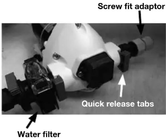
Galvanised Parts Wet storage stain (white rust)
Hot dip galvanising has been used for many years throughout the automotive industry and is widely regarded as one of the best forms of corrosion protection.
When the steel is withdrawn from the galvanising bath it has a clean, bright surface. Over a period of time this changes to a dull grey colour as the surface zinc reacts with oxygen, water and carbon dioxide in the atmosphere to form a tough, stable, protective layer.
During this time, if galvanised items are stored in damp or wet conditions, where there is little or no air movement then the zinc will continue to react with the moisture that is present. In so doing the zinc will produce excessive amounts of zinc hydroxide. This is seen as a bulky white deposit on the surface of the galvanising and is often referred to as wet storage stain(white rust).
You can help to prevent wet storage stain (white rust) occurring. You can do this by washing the chassis with clean water. You must then allow an adequate flow of dry air to ensure that they dry off completely.
The caravan should not be parked on long grass where the air flow around the chassis is hindered and the dampness retained. It is most likely that the chassis will rapidly show signs of wet storage stain under these conditions.
It is also very important to do this during the winter months to ensure all salt deposits from road spray are completely rinsed off.
AL-KO chassis
Manufactured from high quality steel, the chassis has extra deep sections to provide strength at points of maximum stress. Large elongated holes are punched in the longitudinal chassis members, to reduce weight to a minimum. Each hole incorporates a return flange to maintain the required strength and provide rigidity in the extra deep sections.
The chassis frame is of a bolted construction which allows replacement of individual parts should the need arise.
The chassis is Hot Dipped Galvanised. This is regarded as one of the best forms of corrosion protection. It does however require minimal maintenance in certain circumstances and should, if properly maintained, last the lifetime of the vehicle.
When new, the chassis is of a bright and shiny appearance. As the galvanising cures during the initial 2/3 month period, this will gradually change to a medium/dark grey colour. This grey finish is the ideal, giving the correct protective coating. During this curing period the surface should be protected to avoid possible wet storage stain, in the form of a soft, light coloured, porous, oxidation layer. If the chassis members are in contact with any salt deposits from roads this should immediately be washed off with a high pressure washer. Salt attracts moisture allowing the surfaces to remain wet, this prevents curing and also allows formation of wet storage stain.
It is recommended that the chassis/components are washed off, using a pressure washer on an annual basis (especially after winter usage), to avoid undesirable build up of salt and dirt deposits.
The galvanised chassis should not be painted or subjected to any other protective treatment.
Should the galvanising become superficially damaged exposing the steel core, this should be cleaned and treated with a Cold Galvanising Spray obtainable from vehicle accessory outlets.
Damage to chassis members through impact etc, MUST NOT be straightened or welded. Damaged chassis members MUST be replaced.
Drilling or Welding of Parts or Accessories
The chassis is designed and built to precise tolerances and must not be drilled or welded (except in accordance with certain AL-KO Accessory Operating Instructions). Failure to comply will invalidate all warranties.
AL-KO ATC trailer control system (where fitted)
AL-KO ATC is an electronic, emergency Control system for caravans and trailers. It automatically recognises critical swinging motions and applies the caravan brakes accordingly to regain control of the caravan and car.
General notices
Read and act in accordance with the following operating instructions before attempting to use AL-KO ATC. AL-KO ATC is a safety related product and, therefore, should only be fitted by an authorised AL-KO trained technician with experience of working with electrical installations. Any evidence of removal or disassembly, other than by trained technicians, will immediately invalidate the product warranty.
Safety Information
AL-KO ATC is a passive safety product that activates the braking system on the caravan in unsafe driving conditions. The driver has a responsibility under law to ensure that the elements of towing safety are met, including driving within the legal speed limit, consideration of road, weather and other traffic conditions, correct loading and coupling of the caravan.
AL-KO ATC is designed to fit only on AL-KO Chassis and is not suitable for non AL-KO Chassis. AL-KO ATC only functions on caravans with a rigid towbar. The electrical connection between the towing vehicle and caravan must be in good working order.
AL-KO ATC CONTROL SYSTEM
| Display Colour | ATC Condition | Diagnosis What to do Outcome Status | |||
| Green ATC Active Everything | Ok | ||||
| Green Flashing | ATC Active Self test incomplete | Drive forward to detect movement to complete self test and recheck LED. | Green (Constant) | Ready for journey | |
| Red ATC | Inactive | Possible to continue journey | Remove 13 Pin plug and wait 5 seconds. Reconnect plug. | Green Red | Ready for journeyATC Error logfile memory exceeded.Caravan can be towed, but ATC will not apply caravan brakes in the event of instability.See below * |
| Red flashing ATC has detected a fault. | Do not continue a fault with ATC connected | Remove 13 Pin plug and wait 5 seconds. Reconnect the plug | Green Red (flashing) | Ready for journeyATC faulty, and cannot be driven. Remove push-rod as shown on page 207 . Consult AL-KO, see back page for details. | |
| LED not working | ATC has no power | Check push rod position as shown on page 5 of the ALKO ATC manual before continuing journey. | Remove 13 Pin plug and wait 5 seconds. Reconnect the plug. Check for constant live - refer to system requirements. | Green LED not working | Ready for journeyIf power ok, check push rod position: Red line visible - do not drive vehicle.Red line not visible - possible to continue journey but consult AL-KO see back page for details. |
System requirements
ATC draws power from the towing vehicle towbar and requires connection to either: Twin * ATC stores operating errors in a logfile which over time will become full and will result in the solid red light appearing. This needs to be erased and can be done easily by connecting the caravan to a 12 volt supply for a period of 12 hours. The power required to carry out this function is minimal. Most occurrences of these errors are due to power supply problems to ATC which could be due to low voltage, or an intermittent power supply from the towbar.
Maintenance and Warranty
ATC is maintenance free and requires no servicing. In case of any damage to ATC, please contact AL-KO. ATC is a sealed unit and any evidence of removal of ATC or the component parts including outer casing and fixings will immediately invalidate any product warranty.
If ATC is fitted as standard by the vehicle manufacturer then ATC is covered for the same duration of the vehicle warranty or whichever is longer.
If ATC is subject to a call out under warranty and found to comply with the relevant specification or standard, then the cost of any testing or callout charges will be borne by the customer. We reserve the right to request credit card details to cover payment in advance.
Removal of a push rod
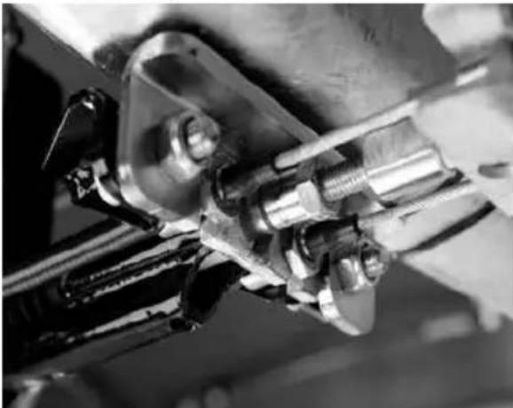
natural_image
Close-up of mechanical components with no visible text or symbolsUsing a 17mm spanner, slacken locking nut on push rod away from Bowden cable abutment as directed above.
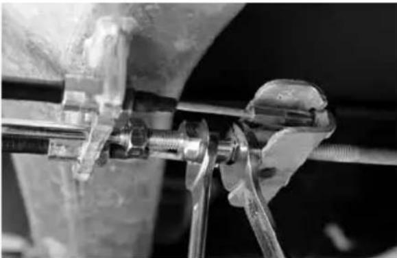
natural_image
Close-up of mechanical clamping or assembly with metal rods and bolts (no visible text or symbols)Unscrew push rod from brake rod and slide it from the guide tube. Remove the locking nut from push rod using two 17mm spanners.
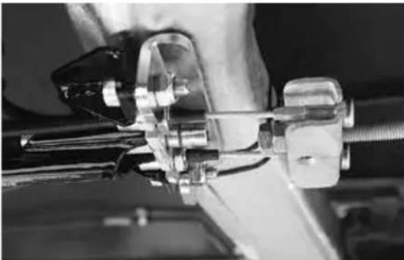
natural_image
Close-up of a mechanical assembly with metal fittings and connectors (no visible text or symbols)Re-apply the removed locking nut onto brake rod thread to secure ball nut as shown above. ATC is now deactivated.
The AL-KO formula optimum safety
The AL-KO formula for optimum safety is a combination of industry leading technology that ensures the safest possible driving conditions for caravan owners. The formula provides total confidence and control when towing a caravan.
AL-KO ATC CONTROL SYSTEM
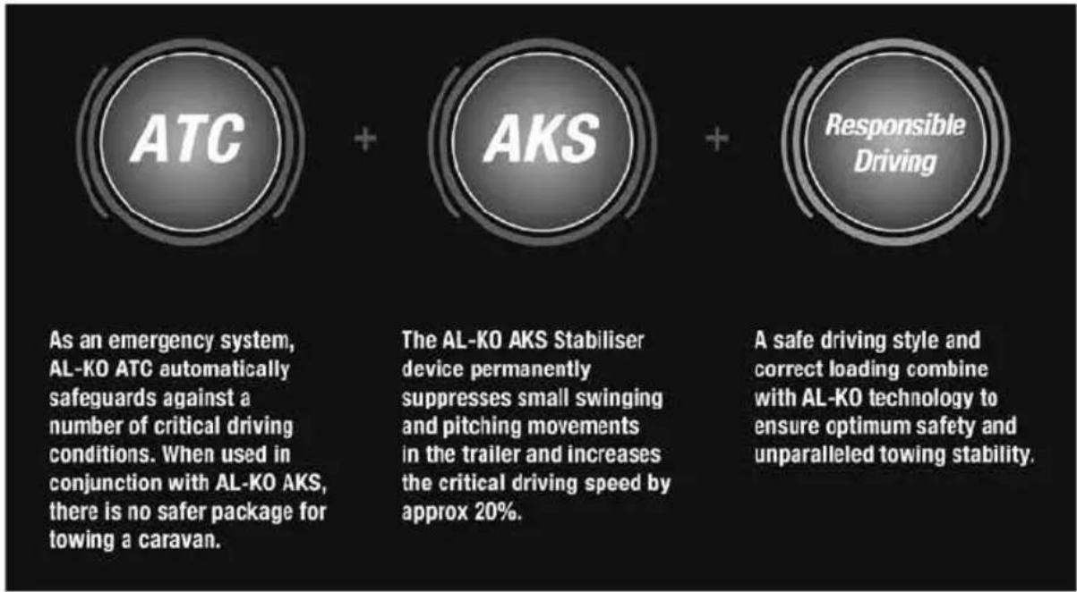
7-Pin Connection
ATC can be connected via the auxiliary 12S (white/grey) plug and requires power on Pins 4 (permanent supply) and 3 (earth). Please ensure that your vehicle towbar is correctly connected to ensure correct ATC operation. This can be checked with the use of a multimeter. Important - A 20 amp fuse is required for the constant 12V supply to Pin 4 on the 12S socket. If only a single fuse is fitted to supply both Pins 4 and Pin 6, the power supply capability of the installation must be checked and a minimum fuse rating of 25 Amps must be used.
13 Pin Connection
ATC can be connected via the 13-Pin plug and requires power on Pins 9 (permanent supply) and 13 (earth). Please ensure that your vehicle towbar is correctly connected to ensure correct ATC operation. This can be checked with the use of a multimeter.
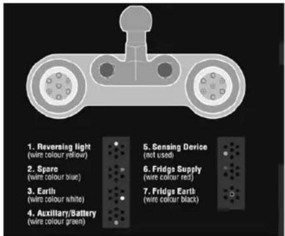
Operating instructions
After coupling the caravan correctly to the towing vehicle, connect the 12N & 12S plugs or the 13 Pin plug to the towbar.
Upon connection, ATC will carry out an initial self test and the LED light on the front fairing will light up RED. During the self test, the sound of the push rod moving inside ATC can be heard. When the self test is complete, the LED will turn GREEN or flashing GREEN to signal that ATC is active. If the LED does not change to green, then ATC is not functioning correctly. The table provided on page 206 details what to do in this case. Prior to commencing any journey, ensure that the
caravan lighting is fully operational and check the vehicle is loaded appropriately, the nose weight and tyre pressures are correct, and confirm that the caravan is coupled to the vehicle with the breakaway cable correctly applied. Always re-check the ATC LED is green after any interval during a journey, such as a service station break.
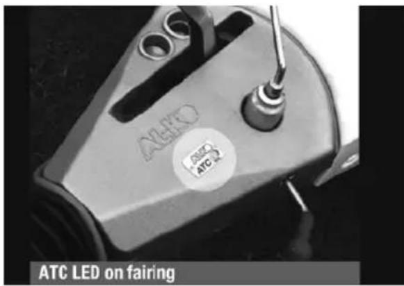
Troubleshooting
Should you experience a fault with ATC, the LED light on the fairing will change colour. Therefore, refer to the table on page 206 and follow the instructions. If no illumination of the LED is evident, refer to system requirements on page 207 and check towbar wiring for permanent supply.
In the unlikely event that you receive a red flashing LED light and disconnecting and re-connecting the power does not alleviate the problem, check the push rod position as detailed below. Locate ATC on the axle and check the position of the push rod. If no red line is visible, ATC is not active, and can be driven. However, we recommend that you contact AL-KO at the earliest convenience.
If the red line is visible on the push rod, as shown on the left, the caravan should not be moved. The push rod needs to be removed to deactivate ATC. Using two 17mm spanners, the removal process is as shown opposite.
Loadings on Coupling Heads, Overrun Assemblies and Axles
The permitted ‘nose’ weights of the coupling head/stabiliser, overrun assembly and drawbars, must never exceed the lowest value stamped on the assemblies.
Fig. 1
The maximum axle loading is that stamped on the plate (Fig. 1 example axle plate) located in the centre of the axle, facing rearwards.
Note: Do not attempt to remove as this will void the plate.
The third line down marked "Capacity" is the maximum permitted axle loading and must not be exceeded.
The caravan manufacturer may have stated a lower maximum loading weight on the plate fitted adjacent to the entrance door, this then becomes the maximum permitted load and must not be exceeded. We recommend you record the Axle details for future reference.
It may be possible if required for the caravans MTPLM to be upgraded.
Your caravan dealer will require the following details from the axle plate.
(Example of information ref Fig 1)
- Order - CHA402248
- Qty - 1 of 2
- Date - 3 May 05
- Type - B850-10
- Capacity - 1000E
Please consult your Swift Group Dealer to confirm if this is possible.
AXLE
Loading
Loads to be carried in the caravan should be placed directly over, or as close as possible to the axles, otherwise the handling will be impaired. Maximum gross weight, as advised by the caravan manufacturer, must not be exceeded without approval from AL-KO.
Maximum loading is defined as the difference between ex-works weight and the permitted total weight.
Load Too Far Forward (Fig 2)
Steering and braking ability reduced. Increased loading on the rear axle and chassis of the tow vehicle.
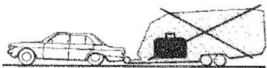
natural_image
Simple line drawing of a car pulling a truck with a suitcase (no text or symbols)Fig. 2
Load Too Far Back (Fig. 3)
High skid risk together with poor braking effect.
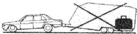
natural_image
Simple line drawing of a car pulling a large truck with a crossbar (no text or symbols)Fig. 3
Load Over Axle (Fig 4)
Optimum road holding together with maximum braking effect. Exceptionally heavy loads should be placed directly over the axle.
Attention should be paid to the legal regulations regarding the permitted pressure exerted by the towbar on the towed unit.
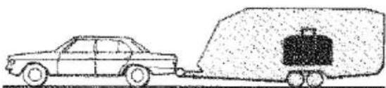
natural_image
Side view of a car with a cargo truck and luggage on its side (no text or symbols)Fig. 4
Axle types
Safety Precautions
No welding is permitted on AL-KO Axles
It is important that the wheel and hub / brake drum are compatible. This mean that the PCD, wheelbolts and inset must all be compatible with both the hub/brake drum and the wheel rim.
Particular attention must be paid to the recommended torque figures for the wheelbolts (see pg 24).
The axle type details shown on axle type plates must not be obscured or made illegible by application of any additional surface finish.
Operating Instructions
Service Brake
When the towing vehicle is braking or travelling down hill, the overrun device shaft is pushed in (dependent on the magnitude of the thrust on the shaft) and presses on the overrun lever. This acts on the bowden cables and expander mechanism, which in turn expands the brake shoes applying the wheel brakes.
Hand brake
With the gas strut version, pull the handbrake lever until upright. With the spring cylinder version, pull the handbrake lever right up to the last tooth. The caravan is then braked.
⚠ WARNING: Please note that with the handbrake fully applied, the caravan/trailer is able to move backwards by 25 cms until the spring cylinder/gas spring takes effect.
Maintenance and Cleaning
Maintenance of Euro-Plus/Euro-Compact and Euro-Delta.
The above semi-trailing axles come fitted with maintenance free wheel bearings (greased and sealed for life) and no adjustment is necessary.
Note: The hub bearing is not protected against water ingress. Check wheel brake linings for wear every 10,000 kilometers (6200 miles) or every 12 months via the inspection hole
Fig. 5
(Fig. 5/Item 1). Adjust if necessary. Where continuous travel in hilly regions or high mileage is experienced, earlier inspection and adjustment may be necessary.
Note: The flanged hub-nut, located under the dust cap, used to keep the brake drum in situ, is a ONE-SHOT NUT (ie. must only be used once). If removed it must be replaced with a NEW flanged nut - torqued to 290 ± 10 Nm (214 +/- 1 7.5 lbs/ft). A small amount of special mineral grease, available from AL-KO must be applied to stub axle thread prior to fitting the new flanged nut. After fitting excess grease must be removed with white spirit.
The rear hexagon cap head bolt located under the black plastic cap MUST NOT BE DISTURBED under any circumstance. Interference with this nut will result in immediate tyre wear and damage to the braking system and WILL INVALIDATE ALL WARRANTIES. Should the rear nut accidentally be disturbed then the complete axle must be returned to AL-KO for resetting of the toe-in and camber.
No attempt should be made to remove the bearing. In the event of damage to the bearing or drum, only the drum complete with bearing and circlip will be available as a spare. No grease is used in the hub other than the mineral grease on the stub axle. No grease should be placed in the DUST cap. This is not a grease cap as used in all previous hubs
Spare parts
Spare parts are safety critical parts! For this reason when fitting spare parts we recommend the use of original AL-KO parts or those parts that they have explicitly approved. The reliability, safety and suitability of parts designed especially for their products, has been determined using a special test procedure. In spite of constantly monitoring the market they are unable to assess or vouch for other products.
If repair work or servicing is required, AL-KO have a large network of AL-KO service stations throughout Europe.
To establish the correct spare parts required for your axle you should always quote the axle type (axle identification plate Fig. 1, page 209) and Spare Part Identification no. (ETI No.), which will be stamped onto the wheel brake or on the identification plate (Fig. 6). Please establish these numbers before contacting AL-KO or a Service Agent.
Fig. 6
The AL-KO rubber suspension axle has been designed and developed to suit all types of road conditions and is maintenance free.
Three rubber elements are contained within an hexagonal axle tube. These provide suspension and have inherent damping characteristics.
Figs. 7, 8 & 9 show the deformation of the rubber elements at the extremes of suspension movement.
The axle is designed to ride with the suspension drop arm at, or slightly below, the horizontal position.
For Trouble Shooting & Fault Finding please see Table 1 on page 225.
natural_image
Technical line drawing of a mechanical component with cross-sectional view (no text or symbols)Fig. 7
natural_image
Technical line drawing of a mechanical component with cross-sectional view (no text or symbols)Fig. 8

natural_image
Cross-sectional diagram of a mechanical component with internal cavities and a cylindrical shaft (no text or labels)Fig. 9
AL-KO braking system adjustment
-
Ensure the towing shaft with coupling head is pulled FULLY FORWARD. (Fig. 10).
-
Release the handbrake to the FULLY OFF position. If the handbrake will not go down the whole way because of the fairing or any other obstruction; then the fairing must be cut away and/or the obstruction removed to achieve this desired position. It will not be possible to set up the braking system properly when the handbrake is not in the FULLY OFF position. (Fig. 10).
-
Jack up one side of the caravan, using the AL-KO Side Lift Jack System. (see Jack Operating Instructions).
-
Remove the inner plastic bung from the backplate to expose the "starwheel" adjuster access. (Figs. 10 & 11).
-
ALWAYS rotating the road wheel in the forward direction - NEVER backwards; adjust the starwheel with a suitable screwdriver, in the direction of the arrow embossed on the backplate until there is resistance in the wheel rotation. (Fig. 11).
-
Slacken off the starwheel adjuster until the road wheel turns freely in the FORWARD direction. (Fig. 11).
-
Check the adjustment at the end of the brake cable where it is secured to the abutment (bracket), welded to the centre of the axle.
When the inner cable is pulled out it should extend between 5 and 8 mm. (Fig.12). (On tandem axles a double abutment (bracket) is fitted to the front axle ONLY).
-
Repeat for other wheel or wheels.
-
On tandem axles the brake cables from the rear axle should pass over this axle and cross over each other, before being connected to the abutment (bracket) on the front axle.
-
Ensure the balance bar (compensator) is being pulled evenly (Figs.10 & 12). Excessive movement to this bar (double on tandem axles) would indicate possible incorrect adjustment (if appropriate, repeat step No. 7 - Fig. 12).
-
Check the brake rod support bracket, (fixed to the floor) IS supporting the brake rod evenly. The brake rod MUST ALWAYS run straight, NEVER bent or curved under any fittings. On tandem axles, using the double balance bar, a brake rod support tube ( ALKO Part No. 228827) MUST ALWAYS be fitted on the end of the brake rod, passing through the centre aperture on the abutment.
-
Remove the slack in the brake rod by adjusting the long ball nut, rear of the balance bar, ensuring the overrun lever makes contact with the end of the towing shaft. Note! Over adjustment to the long ball nut (Fig. 12/Item 2) could induce movement of the inner brake cable, reducing the effective clearance of the brake shoes. If the overrun lever will not make contact, it is
possible the two lock nuts, forward of the spring cylinder, are incorrectly adjusted. Loosen the nuts and adjust brake rod as above (Figs. 10 & 12).
- Adjust the two locking nuts, forward of the spring cylinder (Fig. 10), (on some chassis a single Nyloc nut is used) to give 1 mm of clearance on the spring cylinder. This cylinder (the energy store for the hand-brake operation) must be able to rotate ONLY, not slide on the brake rod. (Fig. 12). (If the overrun assembly is fitted with a gas strut handbrake then no spring cylinder is fitted - therefore ignore this paragraph).
- CORRECT ADJUSTMENT of the linkage is checked by operating the handbrake lever so that when the second or third tooth is engaged, a slight braking force is felt on the road wheels.
- OVER ADJUSTMENT of either the wheel brakes or linkages, will result in difficult reversing causing the wheels to "lock-up".
- When parking, the handbrake lever MUST ALWAYS be engaged into the fully upright position (90°). This is to compress the spring within the spring cylinder and thereby create an energy store which will automatically engage the brakes further should the caravan move. If difficulty is experienced in this operation, try easing the caravan backwards with one hand while engaging the handbrake fully with the other. This manoeuvre should not be attempted on a rearwards facing slope. In this case wheel chocks should be used combined with the handbrake. See page 210 for all handbrake operations.
- Finally, if the road wheels have been removed, re-tighten using a calibrated Torque Wrench (see Changing a wheel). Remember to over-tighten is just as dangerous as to under-tighten, as this can distort the wheel rims. Avoid the use of power wrenches.
⚠ WARNING: The torque settings should be rechecked regularly. Wheel bolts should NEVER be lubricated.
Fig. 10
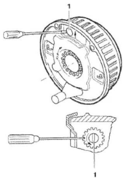
Fig. 11
BRAKE RIGGING FOR SINGLE AXLES
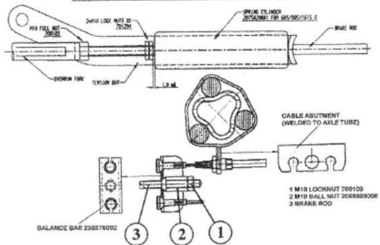
Fig. 12
Regulations
-
The AKS 3004 stabiliser must be used in conjunction with 50mm dia. towballs which conform to EC Directive 94/20 (DIN 74058 or local equivalent).
-
Suitable for attachment to drawbars or approved overrun braking equipment for single (and tandem axle) caravan/trailers, with a minimum weight of 200kg and a maximum permissible weight of 3000kg.
-
EC design approval has been given to the AL-KO AKS 3004 coupling under permit No. e1*94/20*0930*00.
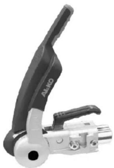
natural_image
Close-up of a black and silver mechanical clamp or tool component (no visible text or symbols)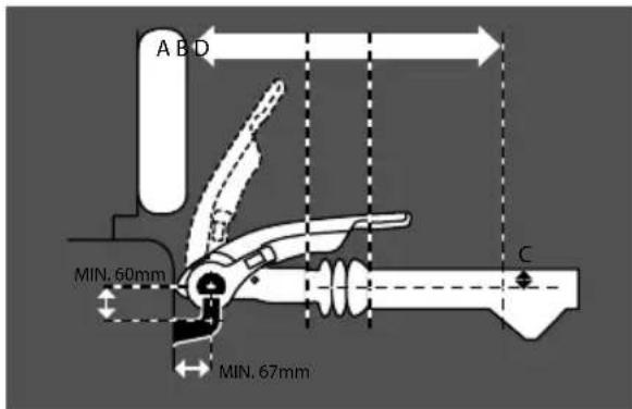
Figure 1 - Necessary clearances
Restrictions of use
- The trailer coupling may only be connected to towing vehicles where the clearances for the stabiliser can be observed, in accordance with EC Directive 94/20 (DIN74058). If these clearances are infringed by special attachments, then the use must be checked separately.
The area above the towball of the vehicle must be free from vehicle components or attachments (A) (e.g. spare wheels, platforms etc.)
The clearance for the stabiliser lever must be at least 330mm (B) + the stroke movement (D) (85mm-100mm), which equates to 440mm when used in conjunction with an AL-KO overrun.
Max. 50mm (C) clearance between the centre of the towball and top of the overrun assembly or fairing, to ensure both coupling handle and stabiliser lever do not foul on operation.
Maintain the same clearances for other manufacturers' overrun assemblies.
- May not be suitable for use with overrun devices which can revolve above 25^ (Fig 2) or BPW overruns fitted with gas strut handbrakes from 2001 model year onwards. (If in any doubt about usage consult your manufacturer).
- Swan Neck towbars (fixed or detachable) are suitable for use with the AKS 3004 providing they comply to EC Directive 94/20 and have the required minimum 60mm clearance, measured from the centre of the towball (Fig 2).
Safety warnings
- In accordance with EC Directive 94/20, couplings of type A 50-1 cannot be used (see Fig 3), your warranty will be invalid if this type of towball is used.
- For UK use, use the extended neck towball (type A50-X).
- A bolted-in type ball coupling (Fig 4) is only permissible if the thread is locked or welded.
HITCH
- The AKS 3004 cannot be used with a laterally attached reversing lever, on the left side, when facing the direction of traffic.
- The towball must be free from grease, paint and other residue, otherwise the stabilising effect is greatly reduced. Coated towballs must have the coating completely removed (use 100 or 120 grain emery paper). If this is not done increased towball wear will occur and may cause damage, or reduce the efficiency of the stabiliser.
- If friction pads become contaminated with grease, they should be replaced.
- The AKS 3004 should only be operated by one person, when opening or closing the handle, to reduce injury risks.
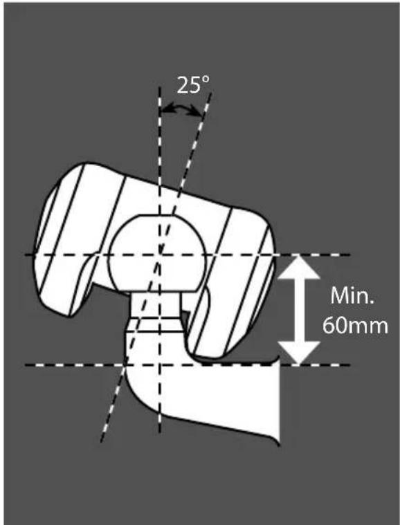
Figure 2 - Max suitable rotation of overrun device is 25^ .
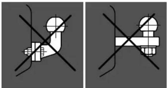
natural_image
Two identical diagrams showing a mechanical joint with crosshair lines, no text or symbols present.Figure 3 - A 50-1 coupling
Figure 4 - Bolted in coupling
AKS 3004 operating instructions
AKS 3004 specifications
Coupling Handle (Fig 7/Item 1)
Stabiliser Lever (Fig 7/Item 2)
Preparation for coupling/uncoupling
The Stabiliser lever (Fig 7/Item 2) must be in the uppermost position (open).
Coupling up
Pull the coupling handle (Fig 8/Item 1) up in the direction of arrow. The coupling mechanism has an open position, as long as the AKS 3004 is not placed on the ball, the handle will remain open. Put the opened coupling onto the clean towball. The handle must now make an audible click and return to the flat position.
⚠ WARNING: The coupling is correctly engaged when the green edge of the safety indicator button is visible (Fig 9/Item 2).
Secure Jockey Wheel for transit:
After coupling fully retract the jockey wheel inner tube so that it locks against the jockey wheel outer tube.
Slacken the jockey wheel clamp handle and raise the complete assembly to its highest position with the wheel facing backwards within the hitch cover ensuring that it doesn't come into contact with the brake rod assembly. Fully tighten the jockey wheel clamp handle to ensure the jockey wheel is firmly held in position.
Stabiliser unit
To operate the stabiliser (once coupled to the towball), simply press the stabiliser lever down as far as it will go (Fig 9/Item 3).
To ensure the stabiliser is correctly coupled, check the arrowhead lines up with the black line marked 2 (Fig 9 /Item 4 and Fig 13/C).
Uncoupling
Pull the stabiliser lever up as far as it will go, open the coupling handle and lift the AKS 3004 from the towball. With larger nose loads, coupling and uncoupling can be made easier by using the jockey wheel to assist lifting.
Note: The friction pads (Fig 10/Items 1, 2 & 3) are pressed against the towball and hence generate a stabilising/damping force. These pads are therefore subject to wear over time, however they will have a long service life (circa.30,000 miles), provided they are well maintained and kept free of grease/dirt.
Operating instructions
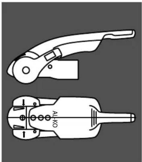
Figure 6 - AKS 3004 stabiliser
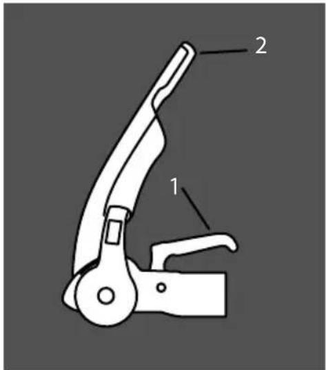
Figure 7 - Raise stabiliser lever
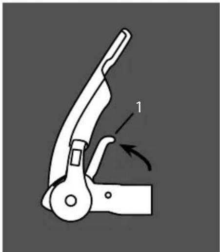
natural_image
Diagram of a mechanical clamp or lever mechanism with labeled component '1' (no text or symbols beyond label)Figure 8 - Pull coupling handle up
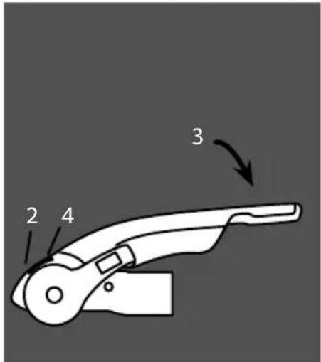
Figure 9 - Correct engagement with towball
HITCH
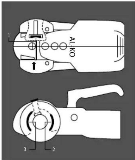
Figure 10 - AKS 3004 friction pads
Manoeuvring
For easier manoeuvring (on campsites etc), pull the stabiliser lever to the 'up' position.
Please do not use the stabiliser lever as a manoeuvring handle. Please use the handles on the caravan or fit the AL-KO manoeuvring handle to your jockey wheel (available separately).
- During opening or closing, the AKS must only be operated by one person.
- Press stabiliser lever down by hand force only. DO NOT use your foot or an extension bar, this will damage the components (below).
- When opening or closing the stabiliser lever, please ensure your hand does not touch the coupling handle - you may accidentally trap your fingers (below).
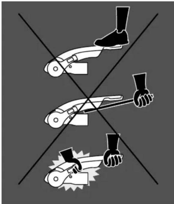
natural_image
Three black-and-white illustrations of a person using a tool to lift a knee, with no text or symbols present.Figure 11 - How not to operate the stabiliser handle
Noises whilst driving
As a rule, the friction pads of the AKS 3004 do not make a noise during driving. Any clicking, creaking or squeaking noises that do arise may be due to the following:
a. Foreign bodies, dirt or exhaust particle build up between the friction pad and towball.
b. Dry operation of the drawshaft inside the overrun device.
c. A detachable towball which has too much play in the locking mechanism.
Remedial action
a. Clean the towball and friction pads before each journey by lightly rubbing the surfaces with a light emery paper (100-120 grit) or use brake cleaning fluid to remove the build up.
b. Lubricate the drawshaft sleeve via the grease nipples. In addition, push the gaiter forward and grease (DIN 51 825 KTA 3K) the exposed part of the shaft (Fig 12).
c. Visit a specialist workshop to have the ball holding area checked for damage and the locking mechanism for function. If necessary, change the towball.
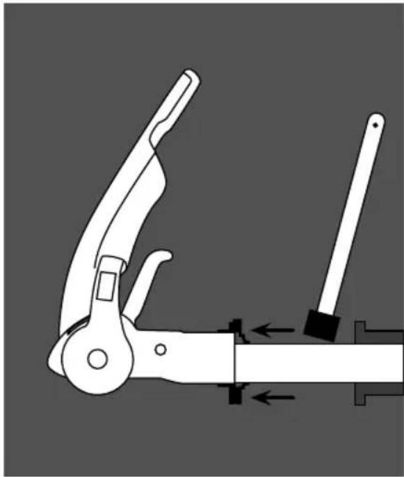
natural_image
Mechanical tool diagram showing a clamp and lever mechanism (no text or symbols)Figure 12 - Remedial action
Checking the efficiency of the side friction pads
- Check that the stabiliser is correctly coupled by ensuring the coupling handle is fully down and the red indicator button is in the raised position.
- Push the stabiliser lever (see diagram - Item 1) down until resistance is felt (i.e. The friction pads are in contact with the ball but not yet under pressure).
- Check the position of the arrowhead on the arm of the stabiliser. If it lines up with the two green lines then the friction pads are still as new (see diagram - A).
- If the arrowhead lines up with the two red lines then the friction pads are worn and should be replaced immediately (see diagram - B).
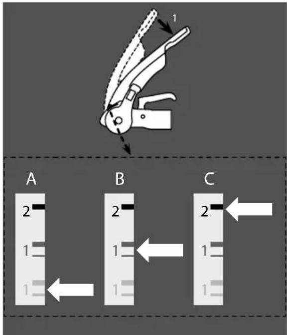
Figure 13 - Checking left / right friction pads
Note: When the stabiliser lever is correctly applied, the arrowhead should line up with the black line marked 2 (see diagram - C).
Note: The friction pads do not require any form of lubrication and should be cleaned with a fine emery paper prior to every journey. It is not necessary to adjust the friction pads.
HITCH
Friction pad replacement (side)
(Replace one at a time)
- Uncouple the AKS 3004 stabiliser.
-
Remove protective caps (see diagram below - Item 1) with the aid of a small screwdriver.
-
Press worn out pad inwards and remove (use punch and hammer) (see diagram below - Item 2).
-
Insert new friction pad from below (after first re-inserting shim washers if they were present) and press in as far as it will go (see diagram below - Item 3 and photo below).
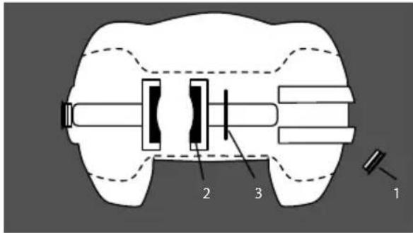
Remove worn pads
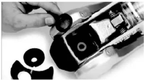
natural_image
Close-up of hands installing or adjusting a mechanical component with a circular component (no visible text or symbols)Insert new pads
Checking the efficiency of the front/rear friction pads
- Couple the AKS 3004 stabiliser to the towball but do not activate the stabiliser.
- If a green indicator is visible (on the handle), then the AKS 3004 is in a new condition or the pads and towball are within the permissible limits (Fig 1 - Item 2).
- If only a red indicator is visible (Fig 2 - Item 3), then this may have the following causes:
a. AKS 3004 is okay but the towball has reached the lowest limit of 49.61mm.
b. AKS 3004 stabiliser shows signs of wear.
c. Towball is in a new condition (50mm) but the front/ rear friction pads show a high degree of wear.
Establish the diameter of the towball so that conclusions may be drawn as to the wear of the friction pads (ball diameter must not be less than 49.61mm).
Friction pad replacement (front/rear)
- Uncouple the AKS 3004 stabiliser.
- Remove the soft dock (pull up & off), (Fig 5 - Item 1).
- Press the safety indicator outwards and secure with SW14 hex. spanner (not included), (Fig 5 - Item 2).
- Remove cheese-head screw (Fig 5 - Item 3 & Fig 18), using special torx tool.
- Press friction lining recess (Fig 5 - Item 4) inwards and pull down and out.
- Open coupling handle (Fig 5 - Item 5).
- Remove countersunk head cap screw using special torx tool (Fig 5 - Item 6 & Fig 4).
- Press friction pad inwards with a screwdriver and remove.
- Fit new friction pads in reverse. Tighten screws to 5Nm (Fig 5 Items 3&6)
- Replace rubber soft dock, insert top section then bottom.
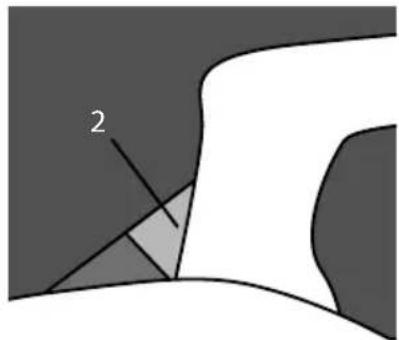
natural_image
Abstract geometric diagram with shaded regions and a labeled point '2' (no text or symbols beyond the number)Fig 1.
Wear indicator - good condition
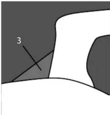
natural_image
Abstract diagram with shaded regions and a labeled point '3' (no text or symbols beyond the number)Fig 2. wear indicator - good condition
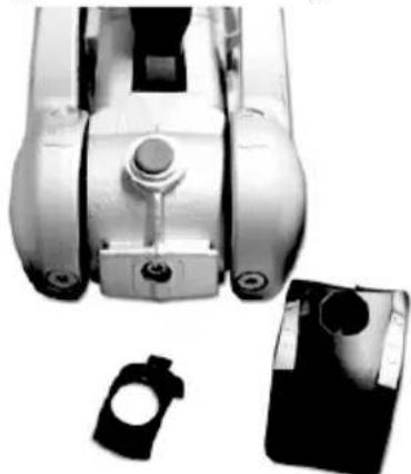
natural_image
Close-up of a mechanical device with multiple circular components and a separate black-and-white close-up (no visible text or symbols)Fig 3. cheese head screw revealed
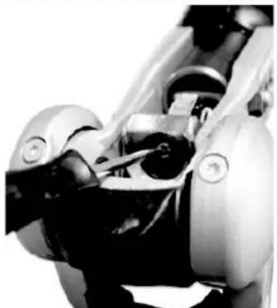
natural_image
Close-up of a robotic arm with visible joints and control buttons (no text or symbols)Fig 4. Remove head cap screw
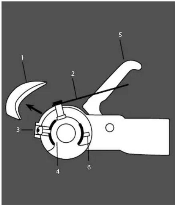
Fig 5. Friction pad revealed
Important maintenance & cleaning advice
- The towball should be cleaned regularly to remove grease or other residue, to maintain the efficiency of the friction pads. The use of thinners, white spirit or brake cleaner is recommended for cleaning the towball and friction pads.
- If friction pads are contaminated, they should not be cleaned but replaced.
- The surface of the towball must be free of grooves, rust or seizing marks.
- Towballs coated with paint or similar, must have this surface completely removed (use 100 or 120 grain emery paper). If this is not done, increased towball wear will occur and may cause damage to the AKS 3004 stabiliser components.
- In winter, you should carefully spray only the visual indicator with de-icer.
HITCH
Lubrication
Should lubrication of the stabiliser parts become necessary, then the following must be observed.
a. Clean all parts thoroughly.
b. Areas may only be covered with a thin film of grease (se diagram).
c. Use multipurpose grease DIN 51825 KTA 3K.
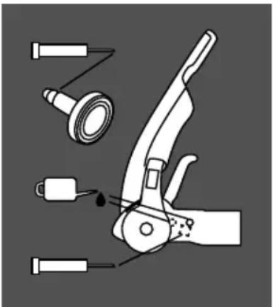
natural_image
Illustration of a manual pliers with attached tools and a droplet, no text or symbols present⚠ WARNING: When lubricating, ensure none gets into the friction pad or towball holding area.
FAQS
Stabiliser
Can the red and/or green indicator buttons be replaced if broken/missing?
This is usually caused by catching the button with the hitch lock when fitting the hitch lock. The green section can in some circumstances be replaced. Please contact AL-KO for further advice. The red part cannot be replaced.
The stabiliser arms keep lifting up when I travel. The most likely cause is the handbrake handle catching on the stabiliser lever when braking.
Gently tease the handle away from the contact point - 5mm should be sufficient. Whilst doing this, make sure you support the base of the handbrake with a block of wood to stop it coming off the ratchet plate.
Friction pads
When should I change my friction pads?
The friction pad life expectancy is around 30,000 miles and can be prolonged by regular cleaning with fine grade emery paper. Simply remove them according to the instructions (see Servicing and Cleaning) clean them and replace.
However, they will wear out and this can be monitored via wear indicators on your stabiliser. See pages 219 for wear indicator information, and instructions on changing them.
My friction pads look ‘glassy’ with bits flaking off. Contamination has built up on the pads. This could be due to grease on the towball, spray from the road, diesel fumes or failure to remove all of the coating on the towball.
You need to remove the friction pads according to the instructions on pages 220, and rub them lightly with a fine grade emery paper. AL-KO recommend cleaning the pads in this way after every journey to prevent build up and prolong friction pad life.
When towing I can hear loud creaking or groaning. There are two possible causes:
1 The incorrect towball could be fitted. Check your towball is compatible with your stabiliser, and if it isn't replace it immediately. Failure to do so could result in your caravan becoming unhitched during towing.
The necessary clearances are outlined on page 215, and AL-KO recommends the AL-KO extended neck towball which complies to all the necessary specifications.
2 Contamination may have built up on the friction pads. This could be due to grease on the towball, spray from the road, diesel fumes or failure to remove all of the coating on the towball.
You need to remove the friction pads according to the instructions on page 220 and rub them lightly with a fine grade emery paper.
AL-KO recommend cleaning the pads in this way after every journey to prevent build up and prolong friction pad life.
The end has snapped off of my friction pad. This usually happens when the pads have not been fully disengaged before dropping the stabiliser onto the towball. You will need to replace the friction pad with a new one. To avoid this in future always place, rather than drop, the stabiliser onto the towball and ensure the stabiliser lever has been lifted fully.
Can I tow my caravan without activating the friction pads? Yes, but AL-KO do not recommend it. It is the hitch handle that attaches the stabiliser to the towball. If you do not activate your friction pads then you will have no damping benefits.
Towball
My towball has grease on it. Can I use it with an AKS stabiliser? Under no circumstances can a greased towball be used with an AKS stabiliser. Ensure you remove all grease before hitching up.
Use a cloth to remove the excess grease, and use brake cleaner to remove any residue. We do not recommend methylated spirit as this can leave a greasy residue.
I have an AKS 3004 stabiliser. What is the minimum clearance that i need between the towball and towing vehicle? Minimum clearance is 68mm. This measurement is taken from the centre of the towball to the nearest point of contact with the towing vehicle.
Insufficient clearance will prevent the stabiliser from correct articulation and could damage your car or even cause the stabiliser to become detached from the towball.
Which towballs are compatible with the AKS 3004 stabiliser? The necessary clearances are outlined on page 215, and AL-KO recommends the AL-KO extended neck towball which complies to all the necessary specifications.
The AL-KO extended neck towball is available to purchase online at www.al-ko.co.uk.
I have a new AL-KO towball - do I need to take the paint off? Yes. It is vital that all paint is removed from the towball before use, as it will contaminate the stabiliser friction pads. To remove the paint, simply rub with emery paper, ideally finishing with a coat of brake cleaner fluid to remove any residue.
Complementary products
AL-KO Security Device
AL-KO Security Devices provide a substantial deterrent against the theft of the caravan or trailer. They lock over the coupling handle, preventing unauthorised uncoupling.
Fitting the supplied Safety Ball into the coupling head when the Security Device is applied, prevents the caravan or trailer from being coupled to another vehicle.
The Security Device is manufactured from high density steel and is TUV approved. Visit www.al-ko.co.uk for more information.
Friction pads
Made from low-wear material, four specially engineered friction pads surround the towball and continue to ensure optimum friction damping.
Extended neck towball
Designed especially for use with the AL-KO AKS stabilisers the Extended Neck Towball has an extended machined neck to allow correct stabiliser articulation and clearances.
Hitch cover
Designed to fit the AKS 3004 Stabilisers, the hitch cover will help protect your stabiliser from the elements.
The water/fade resistant padded foam fabric has a velcro fastening and eyelet for padlock security (padlock not included). Visit www.al-ko.co.uk for more information.
AL-KO ATC trailer control
ATC Trailer Control is an electronic braking device for caravans and works in a similar way to ESP on some tow cars. ATC monitors for instability and takes the necessary action to prevent the caravan from snaking by gently
HITCH
applying the caravan brakes, extending the distance between the tow car and caravan and bringing the caravan back into line. ATC has been fitted as standard on a wide range of caravans since its launch in 2007 and is also available for retrofit. For more information on how ATC works, please visit our website at www.al-ko.co.uk.
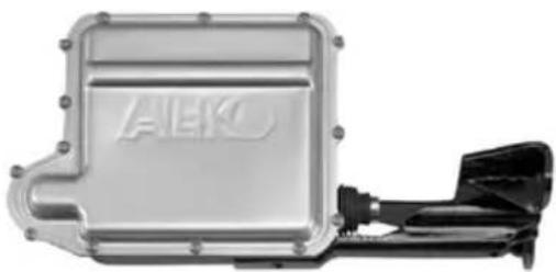
natural_image
Exterior view of a metallic automotive battery pack with visible internal components and mounting brackets (no text or symbols)The AL-KO formula for optimum safety
The AL-KO Formula for Optimum Safety is a combination of industry leading technology that ensures the safest possible driving conditions for caravan owners. When used in conjunction with AL-KO AKS, there is no safer package for towing a caravan.
The AL-KO AKS Stabiliser device permanently suppresses small swinging and pitching movements in the trailer and increases the critical driving speed by approx 20%.
As an emergency system, AL-KO ATC automatically safeguards against a number of critical driving conditions.
A safe driving style and correct loading combine with AL-KO's advanced technology to ensure optimum safety

Coupling Up
Manoeuvre towing vehicle or trailer to coupling point.
Overrun devices fitted with 50 mm coupling head
Fully open coupling head handle and secure hitch onto the towball. See page 25 (coupling up).
Thread the breakaway cable through the breakaway cable guide provided (Fig. 40) and connect it to attachment point provided on towing bracket (Fig. 39). Please refer to 'Braked Trailers Use of Breakaway Cables' for further detail.
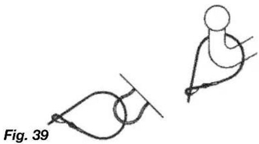
natural_image
Diagram showing two abstract curved shapes with connecting lines, labeled Fig. 39 (no text or symbols on shapes)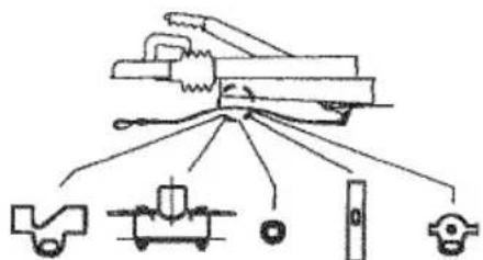
Fig. 40
! WARNING: The breakaway cable operates the handbrake (emergency brake), in the event of the caravan/trailer becoming detached from the towing vehicle during towing. For this emergency brake to work correctly, it is absolutely essential that the following points are observed:
- The breakaway cable MUST run through the breakaway cable guide.
- The breakaway cable MUST NOT be wrapped around the jockey wheel, as this disables the emergency brake (Fig. 41).
- The cable MUST run as straight as possible and not be restricted.
- Ensure the cable is long enough to allow for cornering and will not become taut or snag during use, as this could result in the handbrake operating whilst towing.
Please refer to 'Braked Trailers Use of Breakaway Cables' Information sheet, supplied with your caravan/trailer.
Trouble shooting & fault finding
Table 1 Axles
| Fault Cause Remedy | ||
| Poor Braking Linings | worn or damaged. | Replace Brake Linings. |
| Brake Linings not bedded in. | Will pass after braking a few times. | |
| Brake set up incorrect. | Reset Brakes as page 212-213 & ensure system is lubricated. | |
| Difficulty in Reversing | Braking system set too tightly. | Reset Brakes as page 212-213. |
| Auto-Reverse lever too stiff. | Lubricate and free off Reverse Lever. | |
| Brakes Overheating | Incorrect setting. | Reset Brakes as page 212-213. |
| Braking system not fully released. | Check Handbrake has been released & the system is running freely. | |
| Overrun lever stuck. | Lubricate and free off Reverse Lever. | |
| Damage or Corrosion to braking system | Check system as page 212-213 and repair or renew parts as necessary. | |
| Handbrake Force Low | Incorrect setting of the brakes. | Reset brakes as page 212-213 and lubricate as necessary. |
| Linings not bedded in. | Will pass after braking a few times. | |
| Uncomfortable ride or Uneven Braking | Loose braking adjustment. | Reset brakes as page 212-213. |
| Damper defective. | Check and replace damper if necessary. | |
| Axle shock absorbers defective. | Replace shock absorber. |
CHASSIS TROUBLESHOOTING
Table 2 Coupling Heads
| Fault Cause Remedy | ||
| Coupling does not engage onto ball | Ball diameter too large.Ball could be damaged or deformed.Coupling head dirty or defective. | Change ball to correct size.Fit new ball.Clean & Lubricate coupling and replace if necessary. |
| Difficulty in Uncoupling | Ball damaged or deformed.Coupling damaged or deformed.Coupling head under pressure from damper. | Fit new ball.Replace if necessary.Pull forward a few inches to relieve pressure |
| Too much play in the coupling | Coupling damaged or deformedBall too small | Replace if necessary.Fit new ball. |
Table 3 Overrun Devices
| Fault Cause Remedy | ||
| Poor Braking Overrun shaft tight.Overrun shaft corroded.Body housing damaged. | Lubricate overrun shaft and replace any damaged parts. | |
| Brakes Overheating During Towing | Handbrake not fully released.Braking system incorrectly set.Incorrect attachment of breakaway cable. | Release handbrake.Reset brakes as page 212-213.Ensure correct attachment as listed on page 29 or refer to Braked TrailersUse of Breakaway Cables sheet. |
| Handbrake Force Low | Defective gas strut.Incorrect setting of spring cylinder. | Replace gas strut.Reset spring cylinder as page 212-213. |
| Brakes Apply During Deceleration or Downhill Travel. | Overrun damper is defective. | Replace the overrun damper. |
Accessories
Corner Steadies
Corner Steadies are as stated, for the purpose of steadying the caravan corners. They are NOT JACKS AND SHOULD NEVER BE USED AS SUCH. The screw and pivot pins should be lubricated periodically to ensure their satisfactory operation. (See also Jack Operation).
Shock Absorbers
All AL-KO chassis have pre-punched holes to accommodate Shock Absorbers, in front of the axle. On the Euro-Axle System, axle swing arms have a removable rectangular plastic cap exposing a slot to accommodate retro-fit brackets for the Octagon Shock Absorbers. Delta Axles have Shock Absorbers fitted as standard which MUST NOT BE REMOVED.
Road Wheels
The condition of wheels and tyres should be checked regularly, particularly for distortion of flanges and the wheel dish. Wheels that are damaged or distorted, or have wheel bolt seatings cracked or deformed must not be repaired or used in service - these must be replaced.
⚠ WARNING: The torque settings should be re-checked regularly.
Jacks
The Corner Steadies Should never be used to jack up the caravan. When jacking becomes necessary use the AL-KO Side Lift Jack or 2-Tonne Jack system.
Note: It is essential that the car and caravan are hitched together before commencing jacking. All AL-KO chassis from 1992 onwards have 2 holes punched in the chassis members, each side (rear of the axle); to accept the brackets for the Jack(s). Corner Steadies may be used for stability ONLY, when the caravan is in the jacked position. The caravan should never be lifted by jacking up under the chassis member.
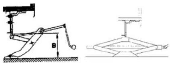
Side Lift Jack 2 Tonne Jack
If working under the caravan in an elevated position, axle stands must be used for safety. Wheel chocks for the opposite wheel(s) are also advisable.
Jockey Wheel
Lubricate screw thread and wheel spindle periodically.
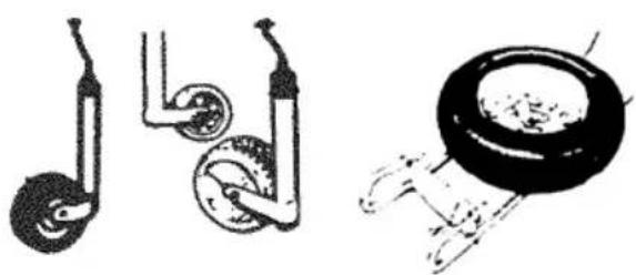
natural_image
Three mechanical diagrams showing different types of wheel assemblies or components (no text or labels)Spare Wheel Carriers
The telescopic frame tubes should be lubricated periodically.
USEFUL INFORMATION
Owners Club 230
Spares and after sales Supercare 230
Repair facilities 230
Caravan Clubs 231
Motoring Associations 231
Trade Association 231
Change of ownership 232
Index 236
USEFUL INFORMATION
Owners club
The Owners Club is a completely independent organisation run for the benefit of the caravan owners. They have numerous rallies during the year in various parts of the country. Apart from the friendliness and companionship the Club generates it is also actively engaged in charity work for those less fortunate than ourselves. The address of the Secretary of the Owners Club can be obtained from the Swift Group website.
Spares and after sales customer care
A catalogue of spare parts are available through our Swift Group Dealer Network, from door catches through to spare wheels. Please note, all parts enquiries must be directed through your dealer, as the Swift Group does not operate a direct retail service.
We endeavour to supply parts for vehicles up to 8 years old. If the original part is no longer available your dealer should be able to source a suitable alternative.
Note: Please remember to quote chassis number when ordering any items from your dealer.
Repair facilities
Should you be unfortunate to encounter damage to your vehicle, we have a number of approved workshops and dealerships with workshop facilities to undertake such repairs. Details of which can be found via our website: www.swiftgroup.co.uk/find-a-dealer
The enjoyment of caravanning can be greatly enhanced by membership of one or more of the various caravanning, motoring and holiday clubs. Here are some useful addresses:
Caravan Clubs
The Caravan Club
East Grinstead House,
East Grinstead
West Sussex, RH19 IUA
Tel: 01342 326944
www.caravanclub.co.uk
The Camping and Caravanning Club
Greenfields House,
Westwood Way,
Coventry,
West Midlands.
Tel: 024 7647 5448
www.campingandcaravanningclub.co.uk
Motoring Associations
Automobile Association (AA)
Fanum House,
Basingstoke,
Hants. RG1 2EA
Tel: 08705 448866
www.theaa.co.uk
e-mail: customer.services@theaa.com
RAC Motoring Services
8 Surrey St.
Norwich
Norfolk
NR1 3NG
Tel: 01922 437 000
www.rac.co.uk
Green Flag National Breakdown
Tel: 0845 246 1557
www.greenflag.com
RBS Insurance
Churchill Cover
West Moreland Road
Bromley, Kent
BR1 1DP
0800 051 3030
Trade Association
NCC
Catherine House,
Victoria Road,
Aldershot,
Hampshire, GU11 1SS
Tel: 01252 318251
www.thencc.org.uk
e-mail: info@thencc.org.uk
© 2014 SWIFT GROUP LTD
Change of ownership
Notification of change of ownership (for second owners only)
As the new second hand owner, please notify the Swift Group of the change of ownership by completing this page, detaching it and sending it to:
Customer Services Department
Swift Group Limited,
Dunswell Road,
Cottingham,
East Yorkshire,
HU16 4JX.
The transfer of ownership incurs an administration charge of £50 payable to 'Swft Group Limited'.
Upon receipt of your completed form, you will be contacted by a member of the Customer Services Team who will process your payment (please do not send payment with this form).
The form and payment must be received within three months from date of purchase.
The transfer of the warranty will not come into effect until payment has been received.
Note: Warranties are only transferable providing the terms and conditions of the warranty have been met by the previous owner(s). Please see warranty information at the beginning of this handbook for full details. The 'Extended Body shell warranty' is a non-transferable warranty.
| Details of motorhome: | Model: | |
| Chassis No: | ||
| New owner: | Name: | |
| Address: | ||
| Email: | ||
| Telephone: | ||
| Mobile: | ||
| Date of purchase: | ||
| Previous owner: | Name: | |
| Address: | ||
| Email: | ||
| Telephone: | ||
| Mobile: | ||
| Date of purchase: |
NOTES
INDEX
Index
Symbols
12V reading lamp 187
13 pin connection 74
13 pin socket 27
A
Acrylic windows 196
AKS 3004 35
AKS 3004 operating instructions ..... 216
Alarm siren 53
Alarm system 51
Alarm tilt sensor 52
Alde operating instructions .... 124
AL-KO ATC trailer control system 205
AL-KO braking system adjustment ..... 212
AL-KO chassis 205
AL-KO operating instructions 50
AL-KO secure immobiliser 49
ALKO Spare wheel and carrier tips 32
Appliance consumption figures 77
Arrival on site 34
Assistance 8
Awning light operation 52
Awnings 188
B
Barbeque point 177
Bathroom / shower 201
Battery box 95
Battery installation 96
Blinds 181
Breakaway cables 29
Bulb replacement and type 201
C
Caravan clubs 231
Caravan exterior 196
Caravan handling 32
Caravan interior 198
Caravan motor movers 18, 189
Caravan movers 196
Caravan terms 14
Caravan towing code 14
Carbon monoxide 41
Care of laminate tops, tables, furniture and doors 186
Change of ownership 233
Changing a wheel 32
Chassis accessories 227
Cleaning 196
CO alarm 41
Colour reference 188
Condensation 197
Cooking guidelines 165
D
Doors 186
Doorscreen 181
Drop down TV mechanism 188
E
Electrical overseas connection 73
Electrical system 73
Escape paths 40
Exterior 230v socket 99
Exterior door 35
Exterior Door Key 182
External shower point 178
F
Fire alarm test 39
Fire and fire alarm 38
Fresh level sensor and cleaning 62
Front locker and sunroof 188
Furniture 201
G
Galvanised steel chassis 22
Gas 68
Gas bottles 68
Gas faults 72
Gas hoses 69
Gas regulator 68
Gas safety advice 70
Gas schematic 67
Generator 98
Green Flag National Breakdown 231
Grill operation 164
H
Habitation relay 98
Heki midi rooflight 185
Internal water tank (UK Caravans) 58
J
Jacking points 33
L
Loading 210
M
Microwave oven 166
Mirrors 31
Modifications 196
Motoring associations 231
Motorway driving 32
Moving off 31
N
NCC 231
0
Owners club 230
P
PIR internal movement sensor 52
Plumbing connections 60
Plumbing troubleshooting 61
Power control system 80
Power control system faults 91
Preparing for the road 20
Pressure switch adjustment 62
Pre-tow check list 24, 25, 26
R
RAC motoring services 231
RBS Insurance 231
Repair facilities 230
Reversing 31
Roller blind advice 183
Roof lights 182
s
Sanitising 64
Security 48
Sensor cleaning 62
Service inspection 10
Shower heads 187
Snaking 22
Solar panel 97
Spares and after sales customer care .... 230
Speed limits 31
Stabiliser friction pads 22
Stability 22
Status 550 directional TV and
FM radio antenna 179
Stopping on a hill 34
INDEX
Suitable towing vehicles 22
Supplier contacts 9
Swift Talk 2
T
Tables 187
Table storage 187
Towball 22
Tow car electrics 27
Towing vehicle's rear suspension 21
Towing vehicle terms 16
Tracker 50
Trade association 231
Truma combination boiler 102
Truma Combination heating system function description 112
Truma CP 25 digital timer control ..... 103
Truma CP Plus digital timer control ..... 103
Truma digital timer control 103
TV inlet in battery box 178
Types of gas 70
Types of tyres fitted 23
Typical gas schematic drawing 67
Tyre maintenance 23
U
Ultraflow water 63
Useful items 18
W
Warranty 6
Water faults 65, 66
Water intake housing 63
Water pump pressure switch adjustment . 62
Water system 56
Water tanks 57
Wheel bolt tightening 33
Windows 182
Winterisation 202
Wiring of connecting cable and caravan mains inlet 76
Work surfaces 201

All Swift Group models have been certified by the National Caravan Council for compliance with stringent European Standards, British Legislation and industry set Codes of Practice specifically relating to health and safety issues.
The approval process covers the testing and inspection of critical areas of the product from fire safety, weights and dimensions, to gas, electrics and ventilation. Every caravan carries the "NCC Approved Caravan" badge.
The NCC also conduct unannounced inspections at the Swift factory to ensure continued compliance. NCC Approval gives you peace of mind that your caravan is legal and safe.
All Swift Group touring caravans are European Whole Vehicle Type Approved.
This is your assurance that these caravans meet all European regulations, and have been constructed and conform to approved standards of safety and manufacturing.
IMPORTANT CUSTOMER NOTICE
TOURING CARAVAN MODEL YEAR
The model year runs from 1st September to 31st August.
For example, the earliest a 2015 model would be registered under the Caravan Registration Identification Scheme (CRiS) is 1st September 2014.

CRiS is the Central Registration & Identification Scheme that issues touring caravan registration documents, equivalent to that of the V5 registration document issues by the DVLA for cars. CRiS was established in 1992 by The National Caravan Council and provides a method of registering the 'keeper' details of every tourer manufactured by NCC member companies to help prevent and detect caravan related crime.
Why register with CRiS?
- Safety • Security • Warranty
Did you know..?
You should not take a tourer abroad without a registration document. If you go abroad your CRiS registration certificate provides the necessary proof, required by the police and other authorities, that you are its registered keeper.
If you need to make a claim on your insurance, CRiS can help speed up claims by providing details of your tourer and its purchase date to relevant parties.
CRiS can help your tourer's manufacturer contact you in the event that there is any kind of product recall or fault that could affect the safety of your caravan.
For help, support and advice Contact CRiS:
NCC CRiS Ltd
PO Box 445
Aldershot
GU11 9SF
Tel 0203 282 1000
www.cris.co.uk
Opening Hours: Monday - Friday 8am to 8pm
Saturday 9am to 5pm
Sunday 10am to 5pm
- Dealer Name:
- Telephone Number:
- E-mail:
- Serial Number:
- Swift Talk
- CONTENTS
- WARRANTY INFORMATION
- WARRANTY
- Your caravan has three warranties:
- SuperSure Warranty
- Body Shell Warranty
- Extended Body Shell Warranty
- Conditions
- Terms
- Exclusions
- ASSISTANCE
- You have legal rights under UK law governing the sale of consumer goods. These warranties do not affect your legal rights.
- Change of ownership
- What to do if you require assistance
- If you have a problem, or enquiry with regards to your new caravan, please follow these steps:
- If you need to contact the Swift Group, please be aware of the following:
- Supplier contacts
- Sargent Electrical Services
- AL-KO Kober Limited
- Truma UK Ltd.
- Thetford Ltd.
- Alde International (UK) Ltd
- Dometic (UK) Ltd
- SERVICE INSPECTION
- Touring caravans - annual service/inspection record
- TOWING CODE
- Caravan towing code
- This Code of Practice contains recommendations jointly reviewed and agreed by the following organisations:
- Scope of the Code
- Caravan terms
- Mass in Running Order:
- Maximum User Payload:
- Personal Effects
- Optional Equipment
- Maximum Technically Permissible Laden Mass (Lower Limit):
- Maximum Technically Permissible Mass (Upper Limit):
- Payload Definition
- Allowances for essential equipment is now contained within the MRO of the caravan and include the following:
- Upgrading of maximum technically permissible laden mass:
- Nose weight:
- Towing vehicle terms
- Kerb weight
- (Mass of Vehicle in Running Order):
- Actual laden weight of caravan
- Kerb weight of towing vehicle
- Maximum Permissible Towing Mass:
- Train Weight (Combination Weight):
- Measurement of nose weight
- Driving licence
- Glossary & checklist
- USEFUL ITEMS
- Caravan motor movers
- Failure to do so may invalidate you warranty.
- Useful memory aid
- Car
- Caravan
- Personal
- Domestic
- Documents
- PREPARING FOR THE ROAD
- Pre-load checklist
- Before loading check:
- How to apportion it
- Towing vehicle's rear suspension
- Do not exceed the:
- STABILITY
- Galvanised steel chassis
- Towball
- Stabiliser friction pads
- Suitable towing vehicles
- Snaking
- Causes:
- Cures
- On the road
- Types of tyres fitted
- Tyres
- Tyre maintenance
- Tread depth
- Pressures
- Tread
- Tyre valves
- Tyre aging
- THE TYRE LAW
- Tyre types
- Wheels
- Wheel rims
- PRE-TOW CHECK LIST
- Hitch head load capacity
- Pre-tow checklist and hitch-up for AKS 3004 stabiliser
- Fit extending mirrors
- Pin socket
- TOW CAR ELECTRICS
- LED Road Lighting
- Caravan 13 Pin Connection - care advice
- Passengers
- Breakaway cables
- Purpose
- Identification
- Operation
- Correct procedure for use
- BREAKAWAY CABLE
- Mirrors
- Moving off
- Reversing
- Speed limits
- CARAVAN HANDLING
- Motorway driving
- Important points
- ALKO Spare wheel carrier tips
- Changing a wheel
- Wheel bolt tightening
- Jacking points
- STOPPING ON A HILL
- Arrival on site
- Manoeuvring your caravan by hand
- Selecting a pitch
- Levelling the caravan
- Exterior door
- Unhitching
- AKS 3004
- SAFETY AND SECURITY
- FIRE AND FIRE ALARM
- Fire
- In case of fire
- Model-si 601 smoke alarm operation
- Normal condition
- Low Battery Condition
- Battery replacement
- Carbon-Zinc type:
- Alkaline Type:
- Lithium (long life) type:
- Alarm test
- FIRE ALARM
- Fire Extinguisher
- Escape paths
- Children
- CO alarm
- Fireangel CO-9D Carbon Monoxide Alarm
- Carbon monoxide
- What are the symptoms of carbon monoxide poisoning?
- What to do during an alarm
- Power Pack Activation
- Power Pack Deactivation
- Operating Features
- Standby Mode
- Power pack, sounder and circuitary test
- Peak Level Reading feature.
- Sensor Testing
- Understanding the Product's Indicators
- Digital Display
- Bar Graph to show early build up of CO.
- The Alarm will sound
- Alarm silence
- Alarm in absence:
- Error signal
- Low power pack signal
- FireAngel Technical Support Line
- Maintenance
- What to do in the event of an alarm
- NEVER IGNORE ANY ALARM.
- Disposal
- Technical Information
- A CARBON MONOXIDE DETECTOR IS NOT A SUBSTITUTE FOR A SMOKE ALARM OR A COMBUSTIBLE GAS DETECTOR.
- VENTILATION/SECURITY
- Year Warranty
- Ventilation
- ⚠ WARNING: Do not obstruct ventilation
- Petrol/Diesel Fumes
- Security
- Caravan theft
- Security chips
- Chassis number
- Additional security
- Caravan insurance
- AL-KO secure immobiliser
- Part A
- Part B
- Part C
- Part D
- TRACKER RETRIEVE UNIT
- You must register your key within one month of the date of purchase. Should you fail to do this, you will not be able to order a spare key!
- Safety information (AL-KO secure)
- AL-KO operating instructions
- The AL-KO side lift jack
- Tracker battery powered retrieve unit
- If in the unfortunate event your vehicle is stolen you should;
- Mobile alarm system
- Stinger 310 alarm (if fitted)
- Operation - using the key fob
- LED Torch button
- Arm / Disarm button
- ALARM SYSTEM
- Awning Light button
- Operation - the PIR internal movement sensor
- Programming Mode button
- One long beep
- - Tilt sensor sensitivity adjustment
- Two long beeps - Beeper volume
- Three long beeps
- - PIR movement detector sensitivity
- Operation - the tilt sensor
- Operation - awning light (model specific)
- Battery - system base unit
- Battery - key fob
- Alarm siren
- System specification
- System base unit:
- PIR movement sensor:
- Key fob controller:
- Spare parts & service
- SERVICES
- WATER SYSTEM
- Water system- Introduction
- Tank types – Overview
- No Internal Water Tank
- On Arrival at the campsite / Priming the system
- WATER TANKS
- Internal Water tank (UK Caravans)
- WINTERISATION / STORAGE
- To use the caravan with the internal water tank:
- To use the caravan with a mains water connection:
- Plumbing Connections
- Troubleshooting
- Pump will not start, when the tap is opened:
- Pump runs, but will not pressurise system (i.e. no or little water being discharged from taps) - Not Pulsing:
- Pump continues to run (for more than 5 seconds) after taps are closed or pump turns on for no reason:
- Noisy or rough operation
- Pump rapidly cycles (switches on or off) or water pulses from taps, including temperature pulsing:
- WATER TANK SENSORS AND PRESSURE SWITCH
- Fresh level sensor & cleaning
- Principle
- Sensor cleaning
- Sensor Cleaning Instructions
- Suggested scourers - food safe
- Water pump pressure switch
- Water pump pressure switch adjustment
- ULTRAFLOW WATER
- Ultraflow water intake housing
- Operating instructions
- Routine maintenance
- Notes
- System care
- SANITISING
- Guidance on cleaning portable water tanks and the water system in touring caravans.
- Separate Water Containers
- For Systems:
- GAS
- General information
- Gas Cylinders
- Gas Hoses
- Cylinder compartment
- DuoControl (Model Specific)
- The Truma Drive Safe Regulator approved for en-route heating
- To use safety devices:
- General
- TYPES OF GAS
- Propane
- Butane
- Gas safety advice
- Facts about LPG
- Awning Spaces LPG Appliance Exhaust
- Precautions
- Connection
- Flue installations
- Thermal insulation heating
- Grade 1
- GAS FAULTS
- Grade 2
- Grade 3
- The electrical system
- On arrival at the campsite
- On departure from the campsite
- Overseas connection
- PIN CONNECTION
- 230V mains electrical equipment power consumption
- ELECTRICS
- EC444 / EC445 / EC455 Power control system
- Introduction
- Using the System
- Power Supply Unit - Models
- EC444 Sprite, Challenger Sport and Eccles Sport
- Power Supply Unit - Component Layout
- EC444/EC445/EC455 POWER CONTROL SYSTEM
- Activating the System
- Connecting to the Mains 230V supply and Safety checks
- Control Panel - Component Layout
- Control Panel Operation
- Operation while driving
- System Technical Information
- Residual Current Device & Miniature Circuit Breakers
- Battery Charger
- Leisure Battery
- a. Type / Selection
- b. Installation & Removal
- c. Operation / Servicing
- 12V Operation of Electrical Items
- 12 Volt DC Fuses
- System Status and Configuration display
- Water System Operation
- Warnings and Alerts
- Contact details
- TECHNICAL DATA & APPROVALS
- Technical Data & Approvals
- Approvals
- The battery box
- ⚠ WARNING:
- Cleaning and maintenance
- BATTERY
- Battery installation
- Solar panel connection point (where supplied - model specific)
- Factory fitted Solar Energy System
- Battery power
- Regulator
- Regulator operation
- Battery charging
- Power Supply Unit
- Control Panel
- Maintenance and cleaning
- Generator usage
- Habitation relay
- Exterior 230V socket
- FITTED EQUIPMENT
- TRUMA COMBI BOILER
- Truma Combination Boiler
- Truma Heating System and Air Flow
- Blown air
- Truma Heating System Control Panel
- Truma CP Plus Digital Timer Control
- Safety instructions
- Important note
- Intended use
- Display and control elements
- Control knob / push button
- Turn to the right (+)
- Turn to the left (-)
- Clicking
- Press (3 seconds)
- Back button
- Functions
- Start / stand-by screen
- Switch on / return to setting level
- Switch off
- Change the room temperature
- Heater
- Air conditioning unit (not normally fitted)
- Change the warm water level
- d = boost \*
- Select power type
- Special aspects in the mixed mode
- Combi Gas
- Malfunction in the combustion process (e.g. lack of fuel)
- Select fan level
- Set timer
- Enter start time
- Enter end time point
- Set the room temperature
- Set the warm water level
- Activate the timer (ON)
- Deactivate the timer (OFF)
- Switch lighting on/off
- Set time
- Service menu
- Query the index status of a connected device
- Change the background lighting of the control panel
- Change language
- Display mains voltage 230 V
- Warning
- Read out the warning code
- Cause rectified / return to setting level
- Cause not rectified / return to setting level
- Malfunctions
- Cause remedied / return to setting level
- Cause not remedied / return to setting level
- Truma Combination Heating System Function Description
- Winter operation (Space heating with water heating)
- Summer operation (Water heating only)
- Repairs may only be carried out by an expert
- Important operating notes
- Room thermostat
- Taking into operation
- Filling the water heater
- Draining the water heater
- There shall be no claims under guarantee for damage caused by frost!
- Fuses 12 V
- Fuses 230 V
- Overheating protection 230 V
- Technical data
- Device category
- Type of gas
- Operating pressure
- Water contents
- Heating up time from approx 15°C to 60°C
- Water pressure
- Rated thermal output
- Gas operation
- Electrical operation
- Mixed operation (gas and electrical)
- Gas consumption
- Air delivery volume
- Combi 4 E:
- Combi 6 E:
- Current input at 12 V
- ALDE HEATING OPERATING INSTRUCTIONS
- Alde Compact 3020
- Specific Use
- Boiler Design
- Gas Heating
- Electric Heating
- Domestic Hot Water
- Draining Freshwater
- Heat Transfer Fluid
- Filling
- Central Heating
- Bleeding Air
- Air Lock
- 230v ELECTRIC
- LPG
- Flue
- WARNING:
- Winter
- Trouble-Shooting
- The system is completely dead, the control panel is blank
- The boiler will not ignite on gas
- The boiler will not heat on 230 V electric
- No hot water
- No central heating
- Alde 3020 - 113
- Colour Touch Operating Instruction
- Starting the system
- Standby screen
- Clock
- Outdoor temperature
- Room temperature
- Circulation pump
- Delayed start
- Day mode
- Gas cylinder status
- Night mode
- 230v supply
- Power button
- Menu button
- Main menu
- Desired Room Temperature
- Shutting down the system
- Setup
- Restore default factory settings
- Setup expansion tank pump
- Setup Antimicrobial function
- Maintenance
- Trouble shooting
- "Panel failure 1" & "Panel failure 2"
- "Gas failure"
- "Overheat red fail" or "Overheat blue fail"
- "Overheat PCB"
- "Fan failure"
- "Connection failure"
- "Window open"
- "Connection fail ext"
- "Low battery"
- "No match Heater/Panel"
- Thetford refrigerator
- LED-control panel
- Main parts
- Introduction
- Use safely
- Use of gas
- Food
- Switch on refrigerator
- Selecting source
- Sources
- Selecting cooling level
- Control of optional extras
- Batteries empty (present with the stand alone models, installed by your dealer)
- Anti-condensation (present on model B)
- Use of refrigerator compartment
- Moving storage shelves
- Moving door bins
- Organising food
- Use of freezer compartment
- Making ice cubes
- While driving
- Door lock
- Winter use
- Cleaning
- Switch off refrigerator
- Defrosting
- Storage
- Questions?
- THETFORD REFRIGERATOR TROUBLESHOOTING
- I just replaced the batteries, but the 'batteries empty' symbol is already
- blinking. What is wrong? Check if you
- FAQ
- Spare Parts
- DOMETIC REFRIGERATOR
- Dometic absorption refrigerator
- Guide to these operating instructions
- Copyright protection
- Limitation of liability
- Customer services
- Environmental notice
- Energy-saving tips
- Application according to regulations
- User's responsibility
- Protection of children when disposing of the equipment
- Working upon and checking the refrigerator
- Information on coolant
- Operating the refrigerator with gas
- Safety instructions when storing foodstuffs
- Instructions for storing food in a refrigerator:
- Refrigerator rating plate
- Refrigerator operation
- Manual energy selection / automatic ignition (RM 8xx1) MES (fridge models)
- Switching ON/OFF
- 230V AC operation
- 12V DC operation (vehicle's battery)
- RM 8XX1 MODELS MES appliances (manual energy selection)
- Additional features
- Gas operation with internal batteries (optional)
- Inserting / changing the batteries
- Explanation of operating controls
- Manual energy selection / automatic ignition (RMD 8xx1) MES
- RMD 85x1 models MES-appliances (manual energy selection)
- Setting of cooling compartment temperature
- Frame heating (fridge freezer models only)
- Operating time: 2 hours
- Operating time: 5 hours
- Permanent operation
- Door locking
- Fastening and releasing the door lock hook when parking the vehicle
- Lighting
- Positioning the storage racks
- Removable freezer compartment
- Winter operation
- Winter operation (fridge freezer models)
- Storing food and making ice cubes
- Storing products in the cooling compartment
- Storing products in the freezer compartment
- Refrigerator compartments
- Shutting off the refrigerator
- DOMETIC REFRIGERATOR TROUBLESHOOTING
- Information on failure display and trouble-shooting
- Status indicators
- Cooker 3 Burner + Hotplate operation
- Important
- Using the Hotplate Gas Burners
- Using the Electric Hotplate
- COOKER OPERATION
- To prime the Hotplate
- To season the Hotplate
- On separate oven & Grill cookers
- Using the Grill
- Using the Oven
- Oven Temperature Control
- Cooking Guidelines
- Do's and don'ts
- Leaks
- Maintenance & servicing
- Cooker 3 burner gas hob (Sprite only)
- Using the hob burners
- Microwave oven general user instructions
- Important safety guidance
- Important instructions
- MICROWAVE
- To reduce the risk of Injury to persons:
- Care of the microwave
- Thetford C260 Cassette Toilet
- CASSETTE TOILET
- Emptying waste-holding tank
- Standard
- Options
- For the latest version of the manual please visit www.thetford.eu
- Possible toilet options
- The following symbols can light up:
- Preparing for use
- Electric ventilator (if applicable)
- Use of your toilet
- Turning the bowl
- Opening the blade
- Electric blade (if applicable)
- Flushing the toilet
- Level indication
- Emptying the tank
- Waste holding tank
- Waste pump out system (if applicable)
- Flush water tank (only for C262 models)
- Remove seat and cover
- FAQs
- I cannot move my waste holding tank.
- What should I do if the blade is blocked?
- Caravans with external barbeque point
- EXTERNAL SHOWER POINT / BATTERY BOX TV INLET
- External shower point
- Caravans with TV inlet in battery box
- Supplier fitted / supplied entertainment equipment
- CD/MP3/tuner with auxiliary input
- STATUS 550 DIRECTIONAL TV AND FM RADIO ANTENNA (model dependant)
- Removing the antenna
- BEDDING
- Lower single beds assembly (Figs. A & B)
- Double bed assembly (Fig. C)
- Lift-up bunks
- Operating instructions for softrollo blinds
- Doorscreen
- BLINDS / ROOFLIGHT / CONQUEROR EXTERIOR DOOR
- Roof lights
- Exterior Door Key
- Exterior Door Operating Instructions- Conqueror
- Windows
- On models fitted with telescopic stays:
- Windows / Roller Blind Advice
- Mini Heki rooflight
- Heki care instructions
- Midi-Heki rooflight
- Intermediate position for the dome
- HEKI ROOFLIGHTS / FURNITURE CARE
- Safety precautions:
- Care instructions:
- Care of laminate tops, tables, furniture and doors
- Doors
- Information
- TABLES / 12V READING LAMP / SHOWER USE
- Tables
- Table storage
- 12V reading lamp
- Shower use
- Fixing of awnings
- Important:
- Awning Sizes
- Colour reference
- Drop down TV mechanism
- Front locker and sunroof
- Bonded Roof
- Step on hitch cover
- Cycle racks
- OMNIVENT
- Use rooflight
- Use of the ventilation
- Remark on the transport of the caravan with Omni-vent
- TOURER REAR VIEW CAMERA
- Tourer Rear Vision System
- If an image is not displayed, please check the following:
- Pairing the transmitter and screen
- Vehicle modifications & non-standard parts
- WD40 is not recommended for external or internal use
- Caravan movers
- Caravan exterior
- Aluminium Panels
- Plastic Panels (GRP/ABS)
- Acrylic Windows
- Acrylic (Plastic) Window Condensation
- Acrylic (Plastic) Window Cleaning
- Condensation
- What is condensation
- Why condensation occurs
- When condensation occurs
- Where condensation occurs
- What is important
- How can you prevent condensation
- Provide ventilation so that moist air can escape.
- EXTERIOR AND INTERIOR MAINTENANCE
- Mould Growth
- New vehicles
- Corrosion
- Changing Exterior Bulbs
- Bulb Replacement and Type
- Caravan interior
- Side Walls, Roof Lining
- Soft Furnishings
- Impala Fabric (model specific)
- Care Instructions
- General dirt and stains
- IMPALA FABRIC
- Cleaning Solutions
- Work Surfaces
- Kitchen Equipment
- Bathroom/Shower
- Furniture
- Kitchen Drainer and Cutting Board
- WINTERISATION
- Servicing
- Electrical
- Gas system
- Appliances
- Exterior (Body / Chassis)
- Interior (Furniture / furnishings)
- Galvanised Parts Wet storage stain (white rust)
- AL-KO chassis
- Drilling or Welding of Parts or Accessories
- AL-KO ATC trailer control system (where fitted)
- General notices
- Safety Information
- AL-KO ATC CONTROL SYSTEM
- System requirements
- Maintenance and Warranty
- The AL-KO formula optimum safety
- 7-Pin Connection
- Loadings on Coupling Heads, Overrun Assemblies and Axles
- AXLE
- Loading
- Load Too Far Forward (Fig 2)
- Load Too Far Back (Fig. 3)
- Load Over Axle (Fig 4)
- Axle types
- Safety Precautions
- Service Brake
- AL-KO braking system adjustment
- Regulations
- Restrictions of use
- Safety warnings
- HITCH
- AKS 3004 operating instructions
- AKS 3004 specifications
- Preparation for coupling/uncoupling
- Coupling up
- Secure Jockey Wheel for transit:
- Stabiliser unit
- Uncoupling
- Manoeuvring
- Noises whilst driving
- Remedial action
- Checking the efficiency of the side friction pads
- Friction pad replacement (side)
- Checking the efficiency of the front/rear friction pads
- Friction pad replacement (front/rear)
- Important maintenance & cleaning advice
- Lubrication
- Stabiliser
- Can the red and/or green indicator buttons be replaced if broken/missing?
- The stabiliser arms keep lifting up when I travel. The most likely cause is the handbrake handle catching on the stabiliser lever when braking.
- Friction pads
- When should I change my friction pads?
- My friction pads look ‘glassy’ with bits flaking off. Contamination has built up on the pads. This could be due to grease on the towball, spray from the road, diesel fumes or failure to remove all of the coating on the towball.
- When towing I can hear loud creaking or groaning. There are two possible causes:
- Complementary products
- AL-KO Security Device
- Extended neck towball
- Hitch cover
- AL-KO ATC trailer control
- The AL-KO formula for optimum safety
- Trouble shooting & fault finding
- CHASSIS TROUBLESHOOTING
- Accessories
- Corner Steadies
- Shock Absorbers
- Road Wheels
- Jacks
- Jockey Wheel
- Spare Wheel Carriers
- USEFUL INFORMATION
- Owners club
- Spares and after sales customer care
- Repair facilities
- Caravan Clubs
- The Caravan Club
- The Camping and Caravanning Club
- Motoring Associations
- RAC Motoring Services
- Green Flag National Breakdown
- RBS Insurance
- Trade Association
- NCC
- Notification of change of ownership (for second owners only)
- The transfer of ownership incurs an administration charge of £50 payable to 'Swft Group Limited'.
- INDEX
- Symbols
- A
- B
- C
- D
- E
- F
- G
- H
- J
- L
- M
- N
- 0
- P
- R
- s
- T
- U
- W
Brand : Swift
Model : Conqueror (2015)
Category : Caravan