USER MANUAL 351.115 SKYTRONIC
- Use proper power source.
Do not use this product with a power source that applies more than specified voltage (100-240V AC).
- Never insert anything metallic into the DVR case.
Putting something into the DVR case can be a source of dangerous electric shock.
- Do not operate in wet & dusty area or use near water.
Avoid places like a damp basement or dusty hallway.
- Do not expose this product to rain or use near water.
If this product accidentally gets wet, unplug it and contact an authorized dealer immediately.
- Keep product surfaces clean and dry.
To clean the outside case of the DVR, use a cloth lightly dampened with water (no solvents).
- Provide proper ventilation.
This DVR has a built in fan that properly ventilates the system.
- Do not attempt to remove the top cover.
If there are any unusual sounds or smells coming from the DVR, unplug it immediately and contact an authorized dealer or service center.
- Do not attempt to remove the top cover.
Warning: You may be subjected to severe electrical shock if you remove the cover of the DVR.
- Handle DVR box carefully.
If you accidentally drop your DVR on any hard surface, it may cause a malfunction. If the DVR doesn't work properly due to physical damage, contact an authorized dealer for repair or exchange.
- Use standard lithium cell battery. (NOTE: Manufacturer has preinstalled battery.)
The standard lithium cell 3v battery located on the mother board should be replaced if the time clock does not hold its time after the power is turned off. Warning: unplug the DVR before replacing battery or you may be subjected to severe electrical shock. Properly dispose of old batteries.
- Make sure there is good air circulation around the unit.
This DVR system uses a hard drive for video storage, which generates heat during operation. Do not block air holes (bottom, upper, sides and back) of the DVR that cool down the system while running. Install or place this product in an area where there is good air circulation.
Chapter 1: DVR Features
| Function Brief | and Description |
| Real-time Monitoring | 2 CH video output, support VGA virtual output, Net-viewer and Mobile Live monitor, and also support zoom in/out, auto sequence and PIP display. |
| Record Function | H.264 video compression format; record quality adjustable, multiple record modes (Always, Scheduled, Manual, Alarm, Motion detection and remote record) |
| Record storage | Support SATA large capacity HDD and save real-time record image to HDD. |
| Playback | Support DVR single CH and multiple CH Search/Playback of recorded files. |
| Backup | Support DVR backup via USB flash drive, removable drive, Recorder and network. |
| Alarm Setting Supports | HDD & video input alarm management. |
| Network operation | Supports remote surveillance by authority users to increase system security. |
| Mouse Operation | Supports Mouse operation for faster menu navigation. |
| PTZ Control Supports | PTZ camera operations through RS-485. |
List 1-1
Other Features:
H. 264 video compression format, supports D1, HD1, CIF resolution
ADPCM audio compression format
Windows Graphical interface
BNC and VGA video out ports
Supports remote live viewing via 3G mobile networks
Supports sending email alerts when motion is detected by system
Triplex (recording, playback and net transmitting at the same time)
Supports USB mouse, IR remote control operation
Rear USB2.0 ports for backup, upgrade and mouse operation.
Supports Double Encode bit network transmission
The video package time is adjustable
Multiple alarm record mode
Multiple language OSD
Supports auto maintenance
Chapter 2: Layout
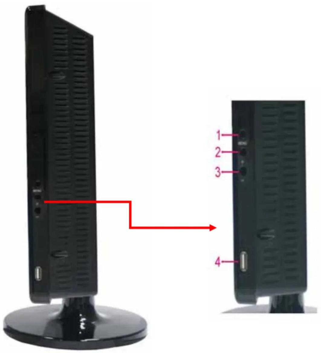
Side Panel
text_image
1
2
3
4
| Item Physical port Connection method |
| 1 MENU Opens MENU-Screen |
| 2 + Increase | |
| 3 - Decrease | |
| 4 USB USB Port | |
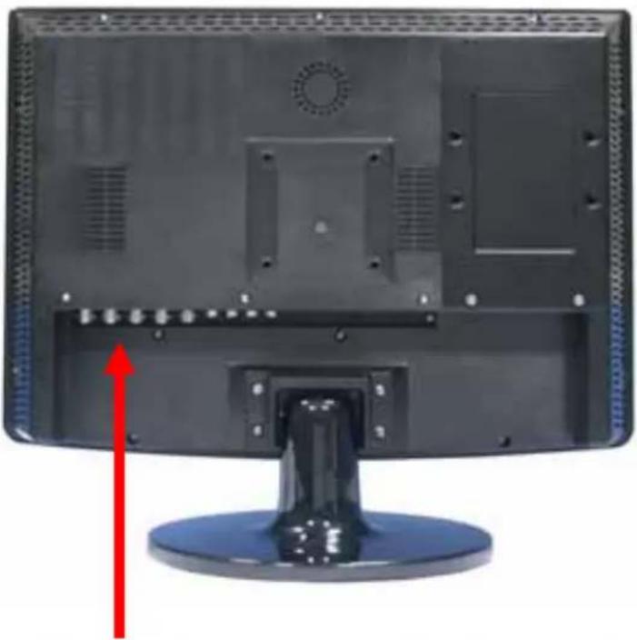
Rear Panel
natural_image
Back view of a computer monitor with visible internal components and a red upward arrow indicator (no text or symbols)
text_image
4CH
1
2
7
8
9
3
4
5
6
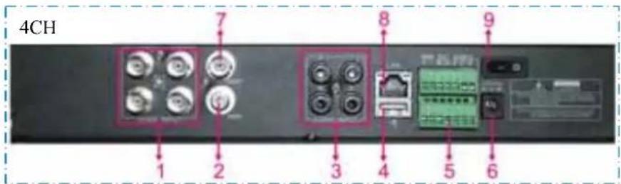
| Item | Physical port Connection method |
| 1 | Video input | Connect CH1-4 video input device (BNC interface) |
| 2 | Audio Output Connect signal output(RCA interface) |
| 3 | Audio input | Connect CH1-4 audio signal input (RCA interface) |
| 4 | USB Port | Connect USB device (Flash Drive, Hard Drive and Recorder etc) |
| 5 | RS-485/Sensor/Alarm | RS485/Sensor/Alarm interface (see pin outs below) |
| 6 | Power Port Connect power supply - DC12V 3A |
| 7 | Video output Connect monitor output (BNC interface) |
| 8 | Ethernet: Port | Connect LAN, Ethernet (RJ45 interface) |
| 9 | Power on/off | |
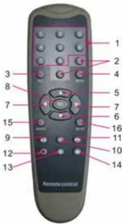
2.3 Remote Control
text_image
1
2
3
4
5
6
7
8
9
10
11
12
13
Remote control
| 1 1-8 | Channel Select 1-8 ; Numeric key |
| 2 | 9、0 | Numeric Key |
| 3 ALL | Preview all Channel |
| 4 Menu | Enter/Exit Main Menu |
| 5 ▲ | | Up Key |
| 6 | ▼ Down Key |
| 7 | ◀ / ▶ | Left / Right Key |
| 8 SEL | Select Key/ Edit Key |
| 9 | ◀◀ | Rewind key |
| 10 | ▶ | Play Key, Enter to recording search menu |
| 11 | ▶▶ | Forward Key |
| 12 | ● | Manual Recording |
| 13 | || | Pause / Frame Play |
| 14 | ■ | Stop manual recording; Stop Playback |
| 15 | Audio | Undefined |
| 16 | Mute | Undefined |
Mouse Operation
You can use a mouse instead of front panel buttons or remote control.
| Click left key of Mouse | In menu lock mode, Enter into pop-up menu and clicking any sub menu to pop up Log-in window; on menu unlock mode, enter into pop-up menu, and then clicking left key to enter into any sub menu directly. |
| After entering main menu, clicking left key could enter into any sub menu; On[Detailed file] menu mode, clicking left key could playback one recording file. |
| Change the status of check box and motion detection area. |
| Clicking combo box to access pull-down menu |
| By clicking left key you can adjust Color control bar and volume control bar. |
| By clicking left key you can select values in edit boxes or pull-down menu and supports Chinese word input, special symbol, numeric and character input, use instead of [Enter- ] or [Backspace] |
| In the [Detailed file] menu mode, clicking left key will playback one recording file. |
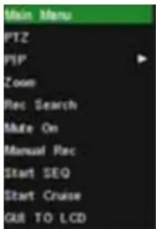
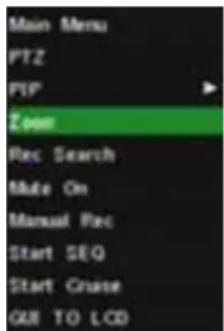
| Click right key of Mouse | In live display mode, clicking right key will display pop-up menu (shown as Picture 5-1). |
| In Main menu or sub menu mode, clicking right key will exit current menu. |
| Double-click Left key of Mouse | In live display or playback mode, double-clicking left key will maximize the screen. |
| Moving Mouse Select menu item |
| Sliding Mouse On motion mode, sliding mouse will select motion area; On [Color set] menu mode, sliding mouse will adjust color control bar and volume control bar. |
List 2-3
Chapter 3: DVR Installation
3.1 Hard Drive Installation
Caution: Please do not Install or take out hard drive when DVR is running!
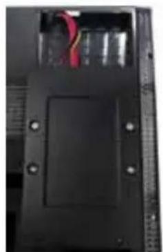
(1) Remove screws on two sides of the body and open DVR upper cover carefully;
(2) Some models has a HDD Drawer; Use provided key to take out. Insert Power Cord and data cable into Pin of hard drive securely;
(3) Put the upper cover back carefully, re-attach screws.
3.2 Camera and Monitor Connection
Connect camera cable to video input of DVR, and from video output of DVR to Monitor via BNC connector (Refer to section2.2-Rear Panel); or
If the camera is a PTZ speed dome, you could connect RS485 A & B to the according port of DVR respectively (refer to system figuration on Chapter 8).
3.3 Power Supply connection
Please only use the power adapter supplied with the DVR.

natural_image
Black rectangular electronic component with mounting holes and a small red pin (no visible text or symbols)

natural_image
Close-up of a hard disk drive with visible power cord and cable, placed on a black electronic device (no text or symbols)
natural_image
Close-up of a black electronic device casing with visible internal components and mounting holes (no text or symbols)

natural_image
Close-up of a black electronic device with a diagonal line inserted, showing internal components (no text or symbols visible)
Chapter 4: DVR Boot up
4.1 System Initialization
text_image
System Initializing...
Picture 4-1
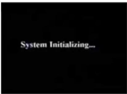
After connecting the power adapter and turning
On the power button, the system will boot-up and start initializing.
4.2 Main Interface

After finishing system initialization the system will enter into main interface. Picture 4-2 is the main interface displayed by system, which is showing no video input status. Once there are video inputs, the interface will display live images from the cameras. In main interface mode, if you use the mouse to double-click the live image of any channel, the image will be maximized to full screen, by double-clicking again, the display will be come back to quad mode displaying all cameras; clicking the right button of the mouse, will enter into Pop-up Menu; by clicking the left button of the mouse, you select menu items; when clicking any area outside the menu, you will exit the Pop-up menu.
Note: When internal HDD is not connected or an error occurs, the character "H" will appear on the first channel of the live screen and accompany buzzer alarm. If you want to close the buzzer alarm, please enter into [Device manage→Alarm setting] to set HDD loss and HDD space to "off".
text_image
Main Menu
PTZ
PIP
Zoom
Rec Search
Mate On
Manual Rec
Start SEQ
Start Cruise
GUI TO LCD
Picture 5-1a
text_image
Main Menu
PTZ
PIP
Zoom
Rec Search
Make On
Manual Rec
Start SEQ
Start Cruise
QUB TO LCD
Picture 5-1b

text_image
and prayed
And the
Picture 5-1c
Note: options of the Pop-up menu will differ depending on different parameter setting and application environment.
After finishing system initialization, click right key of mouse on main interface mode to enter into Pop-up Menu. Now you could proceed parameter setting and operate for Main Menu, Multi Pics, PTZ, PIP, REC Scatch, Mute, Manual REC, Start Rotate, Start Cruise and GUI to VGA etc.
5.2 Main Menu Guide
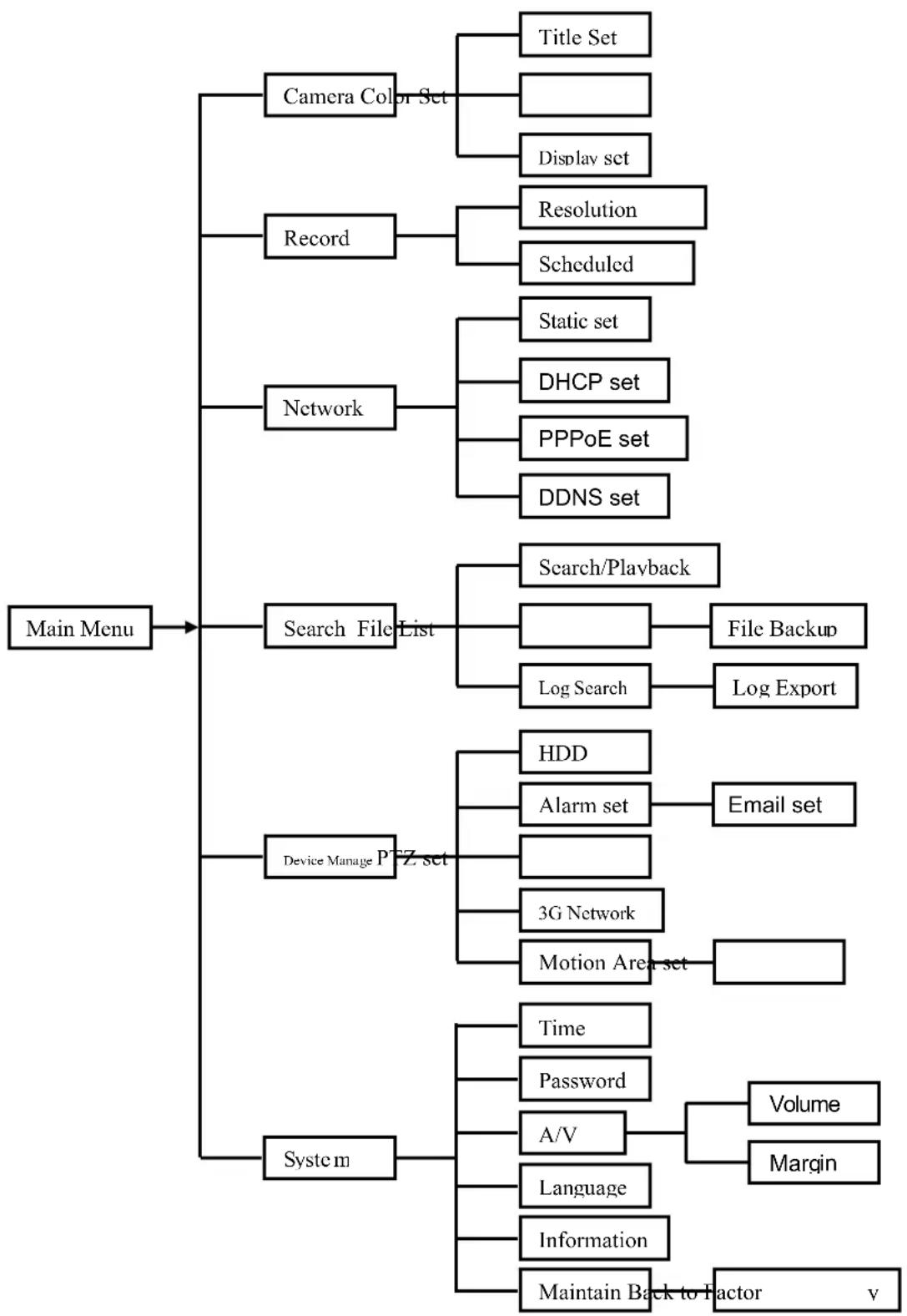
flowchart
graph TD
    A["Main Menu"] --> B["Camera Color Set"]
    A --> C["Record"]
    A --> D["Network"]
    A --> E["Search File List"]
    A --> F["Device Manage P/EZ set"]
    A --> G["System"]

    B --> H["Title Set"]
    B --> I["Display set"]

    C --> J["Resolution"]
    C --> K["Scheduled"]

    D --> L["Static set"]
    D --> M["DHCP set"]
    D --> N["PPPoE set"]
    D --> O["DDNS set"]

    E --> P["Search/Playback"]
    E --> Q["File Backup"]
    E --> R["Log Search"]
    R --> S["Log Export"]

    F --> T["HDD"]
    F --> U["Alarm set"]
    U --> V["Email set"]

    F --> W["3G Network"]
    F --> X["Motion Area set"]

    G --> Y["Time"]
    G --> Z["Password"]
    G --> AA["A/V"]
    AA --> AB["Volume"]
    AA --> AC["Margin"]

    G --> AD["Language"]
    G --> AE["Information"]
    G --> AF["Maintain Back to Factor v"]
5.3 Main Menu
text_image
RISCAR
Display
Record
Network
Search
Device
System
Camera Tools Image Color Time Display
Picture 5-2
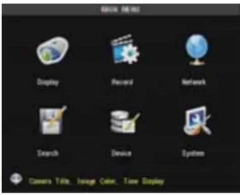
After clicking right button of mouse, pop-up menu will be displayed on the screen. You can click [main menu] button on pop-up menu to enter into Main menu interface (Shown as Picture 5-2). In Main Menu mode, you can control device management settings, such as Display, Recording, Network, Recording search, Device and System settings etc.
5.3.1 Display setup
text_image
BISPLAT Setup
Channel
Name
Position
Color
Live
Live Time
Record Time
Copy To
Default Channel(s)
OK
OK
Setup
Enable
Enable
Enable
Add
Copy
Default Apply Exit
Picture 5-3
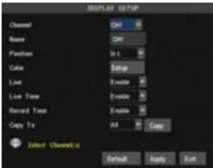
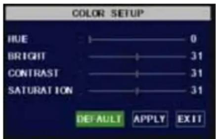
Go to [Main Menu → Camera] to set up the name display and position display of each channel CH (Shown as Picture 5-3), You can also adjust image brightness, saturation, contrast and hue settings of each channel after entering into [Color] Menu and set up whether each channel can be previewed or not under Live display and/or Recording mode.
Please note that the name of each channel supports up to eight characters.
Copy : This function allows you to copy all data of one channel to any other channel.
text_image
COLOR SETUP
HUE 0
BRIGHT 31
CONTRAST 31
SATURATION 31
DEFAULT APPLY EXIT
Picture 5-4
The Color Menu, where you can adjust image brightness, saturation, contrast and hue parameters of each channel.(shown as picture 5-4)
text_image
DISPLAY SETUP
Channel Ctrl
Name Ctrl
Function
Color
Live
Live To
Record
Copy To
Refresh
Using parametric. Please exit.
Default Apply Exit
Picture 5-5
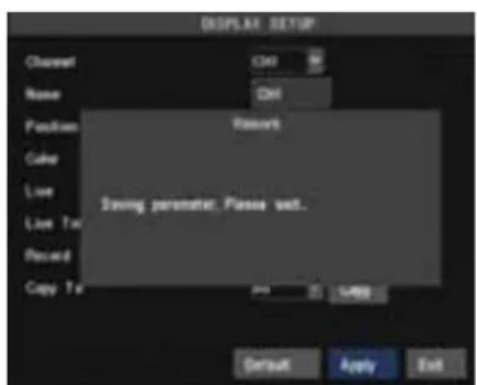
The modifications will be available after clicking [APPLY] button on the bottom of the sub-menu windows and being prompted to save and then clicking [ok] button.
If you want to cancel the modification, click [Exit] button to exit the menu.
When clicking [DEFAULT] button, all system default values will be reset to default value.
System default value indicates the value pre-set at the factory.
5.3.2 Record setup
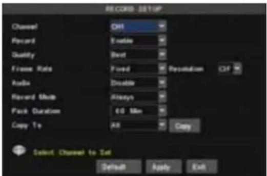
Click [Main Menu] →[Record] to enter into [Record Setup] menu (Shown as Picture 5-6).
➢ [Record] option allows you set up record status (Enable/Disable) of each channel.
➢ [Bit rate] include three options – Best, Good and Normal.
Pack Time : indicates max continuous rec. time (15, 30, 45 and 60minutes)
text_image
RECORD SETUP
Channel ON
Record Enable
Quality Best
Frame Rate Fixed Reputation CIF
Audio Disable
Record Shift Alexys
Pack Duration 60 Min
Copy To All Copy
Select Channel to Set
Default Apply Exit
Picture 5-6 Picture 5-7
text_image
RECORD SCHEDULE XETIM
CN CM
00 06 12 18 23
SUN
MCM
TUE
MFG
TWD
FRI
SAT
Alerts Normal No Record
Copy SUN To AR Copy
Default Apply Exit
The [Record Setup] menu allows you set up recording status (on/off) of each channel, it also allows you setup recording image resolution and quality, and turn audio on/off. This menu also allows you select recording mode (recording after power on and scheduled recording) and recording file length.
Once a channel is set to "on" the channel can record, if it is set to "off" the video from the channel will not be recorded. Resolution options are D1, HD1 and CIF; and Quality options are Best, Good and Normal.
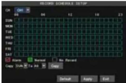
When Audio is set to "On", system will also record audio from the channels and will have audio output on playback mode; if it is set to "off" you can not record audio and will have no audio output available on playback mode. To record 24 hours a day set the Rec Mode to Always. To record on motion or a set schedule, select Time Schedule Record and click the "Schedule" option, the Schedule interface will open as shown in (picture 5-7).
Recording options include All, CH-1, CH-2, CH-3, CH-4 respectively. Please click the channel you need, the channel you select will be highlighted in "Blue" unselected channels will be "Grey".
To setup weekly schedules, click on the box of the recording status you want (Alarm=Red, Normal=Green, or No Record=no Color) and then click on each box in the schedule time line that you want this method to apply to. You can use the [From - To] pull-down menus and Copy button to copy settings from one day to another day or all days. After you complete the schedule you activate it by clicking the [Apply] button. You can also click the Default button to use the system defaults.
5.3.3 Network Setup
text_image
NETWORK SETUP
Type DHCP
Nordy Port 80000
WBD Port 80000
UP/UP Disable
BONE Setup Default Apply Exit
Picture 5-8
text_image
NETWORK SET10F
Type Status
Media Part 26000
WCS Part 00000
IP Address 192.168.051.100
Network 299.200.200.000
Gateway 192.164.001.001
DNS 1 192.168.051.001
DNS 2 000.200.000.000
UPNF Console
DNS Status Default Apply Full
Picture 5-9 Picture 5-10
text_image
NETWORK: 1210P
Type
PPF46
Media Part
85000
Web Part
85000
User Name:
Password:
DND 1
192.198.001.001
DND 2
800.800.000.000
GNDY
3 nodes
COMEX Setup
Default
Apply
Exit
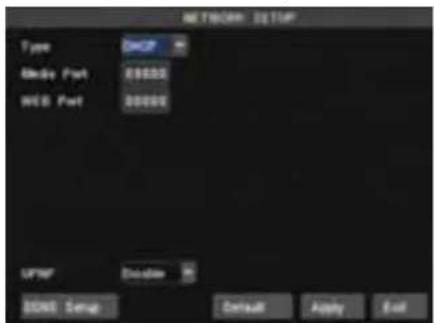
Enter into [Main Menu→Network Set] to proceed network set (Shown as picture 5-8):
After selecting network mode - such as DHCP、PPPOE and static allocation and setup web ports, you could visit DVR remotely via network or internet.
UPnP (Universal Plug and Play) function: If router supports UPnP function and set to On, system will automatically forward port to router.
DNS: DNS server is generally provided by local ISP. Herein please enter the IP address of your DNS.
When selecting DHCP, DHCP server will allocate DVR IP address automatically after you exit the menu.
The IP address of the DVR might change whenever the unit is turn on. Therefore, you need to forward corresponding IP address and web port when you remotely visit the DVR each time.
Processing steps:
1、Select network type (DHCP);
2、Input media port and web port and media port is not equal to web port;
3、Click button and restart, now DVR will capture IP address automatically;
4、If function is set to "Off", you can forward IP address captured by DVR to router and set relative parameter shown as Picture 5-11; If your router support function and set to "on", you no need to perform this step 4;
5、You visit the DVR remotely.
http://internet IP: web port (such as 8080)
http:// intranet IP: web port (such as 8080 only available at the same intranet)
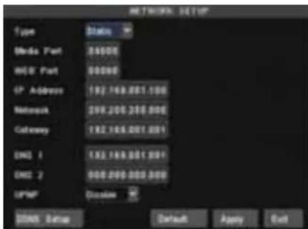
When selecting Static from the Type, user can directly set IP address, Subnet Mask, Gateway, Web Port and DNS shown as Picture 5-9.
● Media Port: manually forward this port to router, details please refers to Picture 5-12.
- Web port: equal to Web Application Manager's web port no and manually forward this port to router.
- IP Address: Input a special IP address, and the IP address is unique in full service intranet.
- Net Mask: consistent with router's
● Gateway: consistent with router's
● DNS: Input DNS server
Click button and restart DVR, all above parameters will be effective. Now you visit the DVR remotely via below IP:
http://public IP: web port (such as 8080)
http://intranet IP: web port (such as 8080)
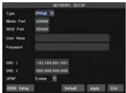
When selecting PPPoE form the Type, user can input user name and password provided by ISP and set Media and Web port (details please refer to the Picture 5-10). You can visit your DVR via public network without port forwarding when network type is set to "PPPoE" and web port is right.
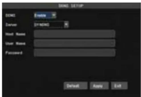
DDNS (Dynamic DNS) is a service that register a domain name and the floating IP address with the DDNS server so that the domain name can be routed to the IP address even if the IP address is changed in a dynamic IP system.
At the bottom of the NETWORK SETUP window there is an option to setup the DVR to be accessed through a DDNS service. When you click on the DDNS button it brings up the window displayed as Picture 5-11. You can access the DVR through a static or dynamic IP address; however a dynamic address can change from time to time. How often depends on your service provider When it changes you need to go to a website such as www.myipaddress.com from a computer attached to the same router as the DVR to find out what the new IP address is.
text_image
DOS Setup
DNS
Driver
Server
D:\NDS\
Host Name:
User Name:
Password:
Default Apply Exit
Picture 5-11
text_image
Virtual Servers
ID Service Port IP Address Protocol Enable
1 8000 182 168.1 101 NULL SP
2 8000 182 168.1 101 NULL SP
3 154 182 168.1 101 NULL SP
4 182 168.1 NULL F
5 182 168.1 NULL F
6 182 168.1 NULL F
7 182 168.1 NULL F
8 182 168.1 NULL F
Common Service Port: (NOS) Copy No: D 1
Clear All Save
Picture 5-12
- Server: select a Dynamic domain name server provided by ISP;
- Host Name: Input host name registered from Dynamic Domain Naming System, for example: DVR2009.3322.org;
- User Name: Input a user name registered before applying for a domain name;
- Password: Input a password you set when registering a user name.
User can enter below website or domain name as per current PC network environment to visit the remote DVR.
http://public IP: Web port (such as 0080)
http://intranet IP: Web port (such as 0080) (only available at the same LAN)
http://superdvr.3322.org: Web port (such as 0080)
Router's Port Forwarding
Port forwarding is required when you want to access the DVR connected to the router from outside of the router's network.
- Input router's IP address from IE-based browser to open the Router configuration interface;
- Click [Transmittal rule] option to take you to the port forwarding instructions for your router;
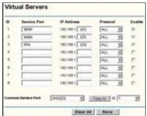
- Set the corresponding parameters illustrated in Picture 5-11. When server port and web port forwarding the DVR IP address, user can visit the DVR remotely.
Friendly Reminder: The router's port forwarding interface may be different; however, when entering into virtual server,
user will always need forward port 8080 and port 9000 of router to IP address of DVR allocated or automatically captured, and select [All] or [Both] in corresponding protocol column and save the above setting.
Above steps may differ from the router device depending on the manufacturer.
5.3.4 Record Search
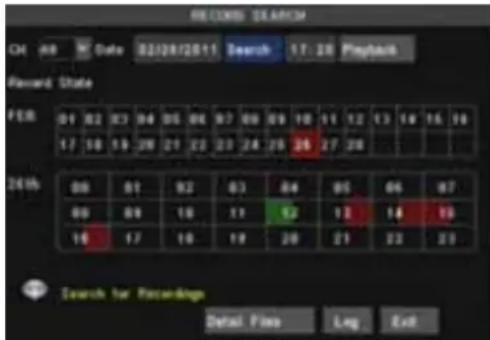
Click [Main Menu→Record Search] to enter into the interface shown as Picture 5-13.
text_image
REMARKS $EARNISH
CH: NR Date 02/28/2011 Search 17:28 Playback
Record State
PER 01 02 03 04 05 06 07 08 09 10 11 12 13 14 15 16
17 18 19 20 21 22 23 24 25 26 27 28
2015 09 01 02 03 04 05 06 07
09 09 10 11 12 13 14 15
16 17 18 19 20 21 22 23
Search for Recordings
Detail: Plans Leg Exit
Picture 5-13
text_image
DETAIL FILES
Type Alt
Oh Time Size Type Select
1 12:00:26-12:00:08 2.0M Normal
2 12:00:26-12:00:09 2.0M Normal
3 12:00:15-12:00:10 2.0M Normal
4 12:00:15-12:00:11 2.0M Normal
5 12:00:27-13:38:01 8.0M Alarm
6 12:00:27-13:56:01 6.0M Alarm
Click to playback
First
Play
Next
Last
Alt
Interms
Back
Exit
Picture 5-14
Time Search: In the Video Search screen, user can search for a specific date and time for a record and view it in Playback mode. This is useful for hunting a specific recording of an incident if you know the date and time it occurred.
Date Search: In the Video Search screen, user can search for all the records in a specific date. To execute a video search, highlight and select the date numeric field, and then click a detailed time quantum of the specific date, system will start the playback from the first recoding of the time quantum.
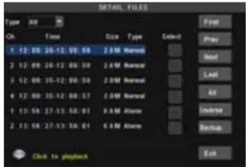
File List: click [File list] button to enter into the [File List] screen shown as Picture 5-14, the video recordings for the time quantum will appear in the screen. Then highlight the record file and click [Playback] button.
Playback Mode: You can use the Playback Control bar to operate the Fast Forward (X2, X4, X8 and X16), Slow play (1/2, 1/4 and 1/8 speed), Play, Pause/Frame, Rewind(X2, X4, X8 and X16). When ending playback, DVR will return back to previous menu.
And you also can filter the records you want to view by the Channel or record mode based on date/time search.
First: Indicates the first page of recording history you have searched. When you view other pages, clicking [First] button brings you back to Page one.
PREV (Previous page): When viewing event list, clicking [Previous page] button will take you back to page before the one you are currently viewing (except the first page).
NEXT (Next page): When viewing event list, clicking [Next page] button will take you to the page after the one you are currently viewing (except the last page).
LAST (Last page): Indicates the last page of recording history you have searched. When you view other pages, clicking [Last page] button will take you to the Last page.
ALL (Select All): Allows you to select all the events on the current page.
INVERSE (Select Invert): Allows you to select other events on the current page except those you have currently selected.
Backup
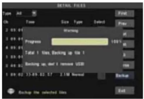
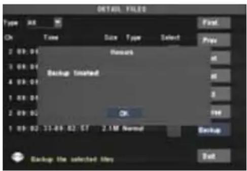
Backup: In [File List] mode, if you wish to backup records, please tick-select the [Select] check-boxes which corresponds to the records and click [Backup] button to enter into the below windows illustrated in Picture 5-15. When backup processing ends, system will prompt you "Backup finished!" shown as Picture 5-16.
text_image
DETAIL FILES
Type Alt
On Time Size Type Select
2 05.01
3 09.01
4 09.01
1 09.01
2 09.02
1 09.02
Status:
Warning
Progress
100%
Total 1 files, Backing up file 1
Backing up, def 1 remove USB
2.1M Normal
Backup
Backup file selected files
End
Picture 5-15
text_image
DETAIL FILED
Type: 36
OK Time Size Type Select
2 09:01 Renack
3 09:01
4 09:01
Backup installed
1 09:01
2 09:02 OK
1 09:02 11:49:52:57 2.1M Normal
Backup file selected May
Back
Picture 5-16
Note:
Backup file will be saved as H264 format; you can playback the recorded files using the Multimedia Player program that comes with the DVR.
Please make sure you have connected backup device, such as USB and DVD, well before backing-up.
Log Search
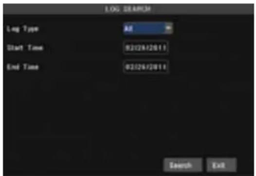
In the screen, Click [Log Search] to pop up the Log search screen shown as Picture 5-17(a).
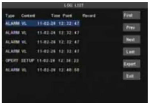
Select log type, enter start date & end date, and then click the [Search] button on the bottom of the interface to search all the logs you need shown as Picture 5-17(b).
text_image
LOG SEARCH
Log Type All
Start Time 02/26/2011
End Time 02/26/2011
Search Exit
Picture 5-17(a)
text_image
LOG LIST
Type Context Time Pinch Record
ALARM VL 11-02-28 12:32:47
ALARM VL 11-02-26 12:32:47
ALARM VL 11-02-26 12:32:47
ALARM VL 11-02-26 12:32:47
OPERT SETUP 11-02-26 12:36:22
ALARM VL 11-02-26 12:40:50
First
Free
Next
Last
Export
Exit
Picture 5-17(b)
Export:
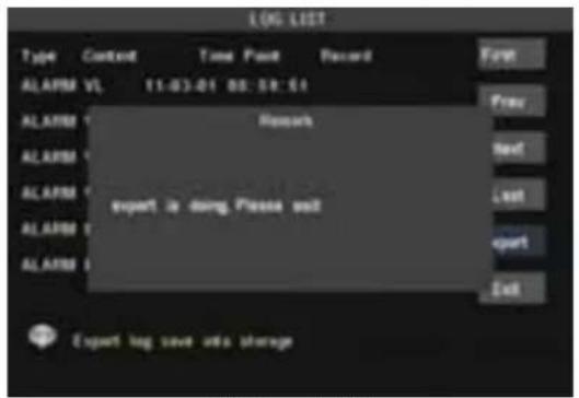
User can export all the logs which have been searched to U flash disk and save it as TXT format. Before exporting the logs, please make sure you have connected the U flash disk well. Detail operations please refer to Picture 5-18.
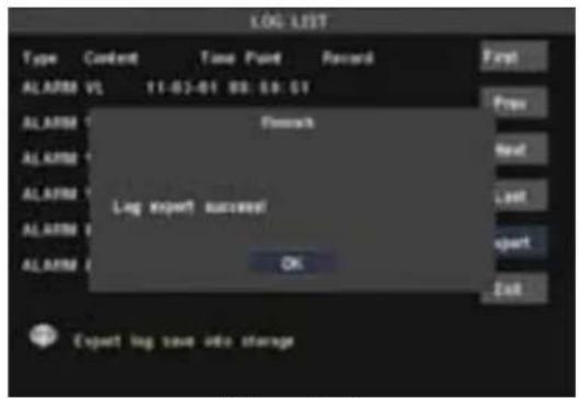
After Log export success, please click [OK] button shown as Picture 5-19.
text_image
LOG LIST
Type Content Time Point Record
ALARM V1 11:03:01 00:58:01
ALARM Report
ALARM Next
ALARM Last
ALARM Export
ALARM Export
ALARM Exit
Export log save info storage
Picture 5-18
text_image
LOG LIST
Type Content Time Point Record
ALARM VL 11-02-01 03:18:01
ALARM
ALARM
ALARM
ALARM
ALARM
ALARM
ALARM
ALARM
ALARM
ALARM
ALARM
ALARM
ALARM
ALARM
ALARM
ALARM
ALARM
ALARM
ALARM
ALARM
ALARM
ALARM
ALARM
ALARM
ALARM
ALARM
ALARM
ALARM
ALARM
ALARM
ALARM
ALARM
ALARM
ALARM
Picture 5-19
5.3.5 Playback Player
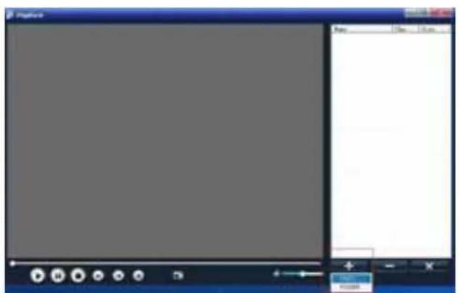
Copy backup file to your PC;
Open Playback Player, and then click [+] button to open the file shown as Picture 5-20
Note: Please select the file with *.264 or *.nvr format. The record file backed-up by U flash disk or removable disk is with *.264 format, and DVD Recorder with *.nvr format.
text_image
Screenshot of a legacy software interface with a blank canvas and control panel, showing menu options and buttons.
Picture 5-20
text_image
File
Locks | AutoPhoto
1.0000000000000000000000000000000000000000000000000000000000000000000000000000000000000000000000000000
2.568888888888888888888888888888888888888888888888888888888888888888
3.4976666666666666666666666666666666666666666666666666666666666666666666
4.3333333333333333333333333333333333333333333333333333333
5.259999999999999999999999999999999999999999999999999999999999999999999999999999999999999999999999999999
Name:
Date: 2/1/2/2/2/2/2/2/2/2/2/2/2/2/2/2/2/2/2/2/2/2/2/2/2/2/2/2/2/2/2/2/2/2/2/2/2/2/2/2/2/2/2/2/2/2/2/2/2/2
File Name: C:\Users\1.1.1.1.1.1.1.1.1.1.1.1.1.1.1.1.1.1.1.1.1.1.1.1.1.1.1.1.1.1.1.1.1.1.1.1.1.1.1.1.1.1.1.1.1.1.1.1.1.1.1
Save
Cancel
Picture 5-20(a)
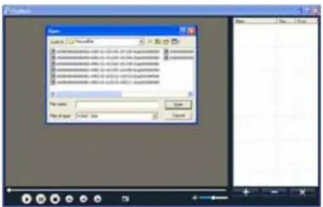
Select the playback file you desired from the file shown as Picture 5-20(a).
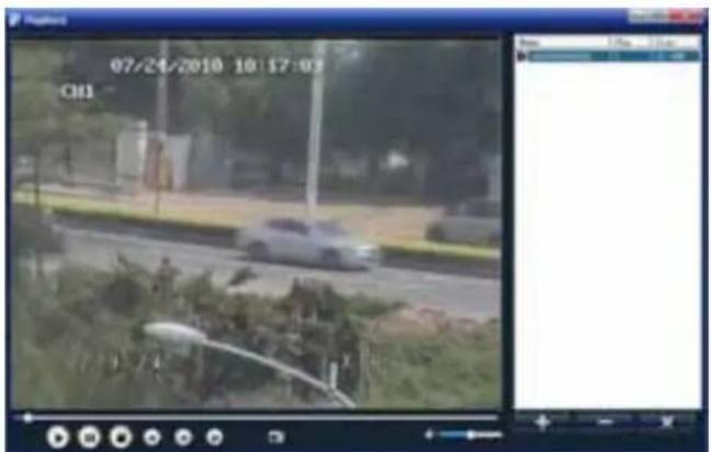
Double-click the record event at the right side of screen to start record file playback shown as Picture 5-21
text_image
07/24/2010 10:17:03
CH1
Picture 5-21
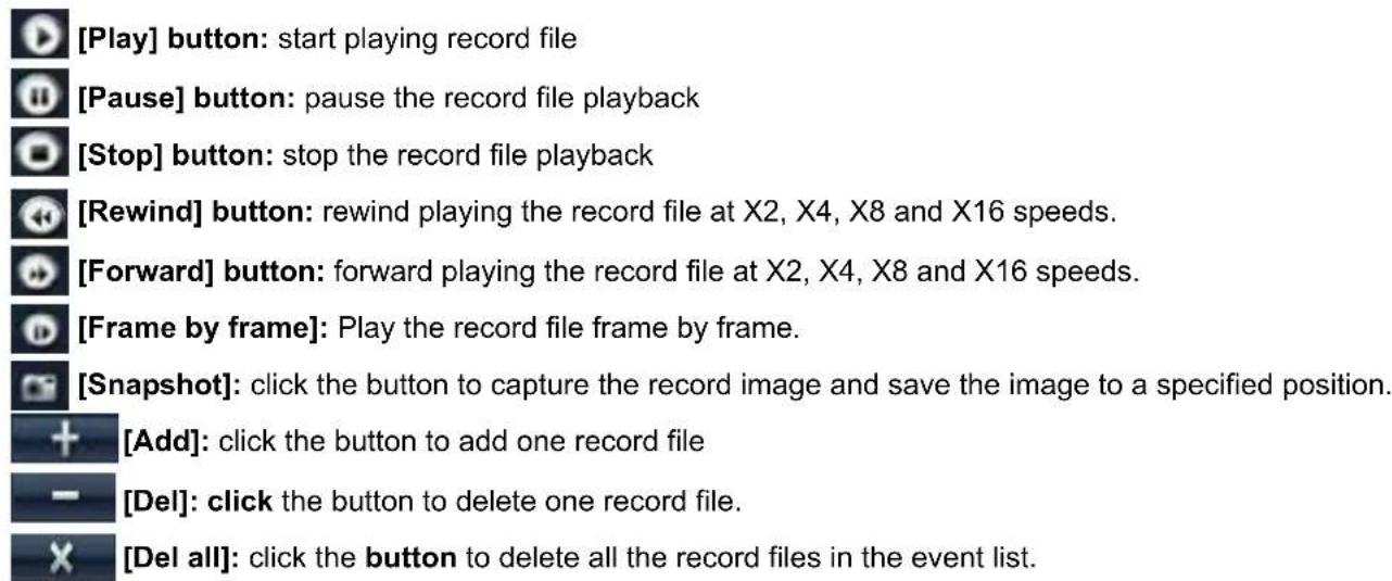
The button functions from left to right in turn are as follows:

text_image
Screenshot of a media player control bar with playback, pause, stop, and video icons
text_image
[Play] button: start playing record file
[Pause] button: pause the record file playback
[Stop] button: stop the record file playback
[Rewind] button: rewind playing the record file at X2, X4, X8 and X16 speeds.
[Forward] button: forward playing the record file at X2, X4, X8 and X16 speeds.
[Frame by frame]: Play the record file frame by frame.
[Snapshot]: click the button to capture the record image and save the image to a specified position.
[Add]: click the button to add one record file
[Del]: click the button to delete one record file.
[Del all]: click the button to delete all the record files in the event list.
5.3.6 Device Management
text_image
DEVICE SUMMARY
HDD
Atom
PT2
Mobile
Motion
Ext
HDD (Information, Format HDD and USB disk)
Picture 5-22
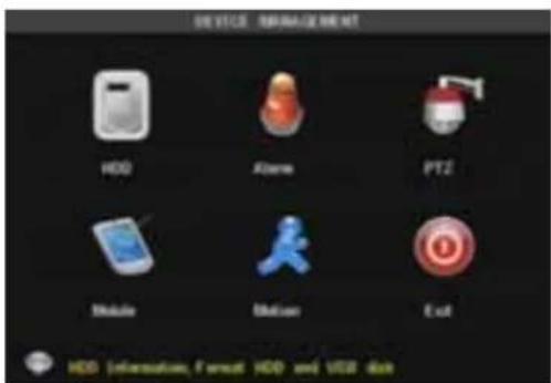
Objects in include HDD, Alarm, PTZ, Mobile and Motion.
Click [Main Menu→Device Management] option to enter into the window shown as Picture 5-22.
5.3.6.1 HDD Management
text_image
HOS - BIOS/CEM-80
NO. State
TataaTree
Available Time
Select
1 Normal 2000X11G Altair
2 No Disk Altair
Overwrite Auto Format HDD Format USB
Outwrite dbdct FaccenBags When IAdd to full
Default Apply Exit
Picture 5-23 Picture 5-24
text_image
HDD - MAX/CE ME
HD State
TotalFree
Available Time
Select
1 Normal 200Q11G Allout
Warning
Forward will remove all data from HDD
Overstands
OK
CANCEL
Cross all under base HDD
Default
Apply
Exit
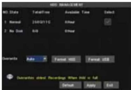
Click [Main Menu→Device → HDD] to enter [HDD Management] menu (shown as Picture 5-23).
When you install a HDD, the system will automatically detect if HDD is formatted or not; If HDD needs to be formatted, HDD status will be shown as "Not format/No disk", otherwise, the HDD status will be shown as "Normal" (refer to Picture 5-24). NO: HDD number defaulted by system
State: Available Hard drive. You could use HDD only when formatting the HDD and inspect its status normal.
TOTAL SPACE: Indicates total space available on Hard Drive.
AVAIL SPACE: Indicates unused space available on the Hard Drive.
USEABLE REC TIME: Based on current image detail/quality and frame rate, system will show you how many Recording time you have left on the Hard Drive.
OVERWRITE: If you select "on" the system will automatically overwrite the oldest recordings once the hard drive is full; if you select "off", recording will stop once the hard drive is full.
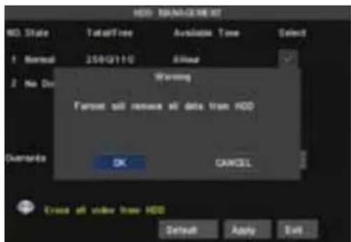
HDD FORMAT: You use this option to format the hard drive, you can not record files to the hard drive until it has been formatted. Click [Format HDD] button to start formatting. When selecting [Format HDD] option the system will prompt you – “Format HDD will loss all the data, do you confirm?”; click “OK”, system will prompt you – “Is formatting…” and “successful format”; and then system will restart automatically.
USB FORMAT: Use this option to format USB devices (Is strongly recommended).
5.3.6.2 Alarm Setup
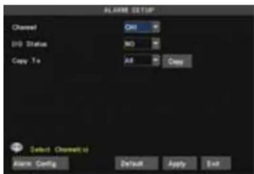
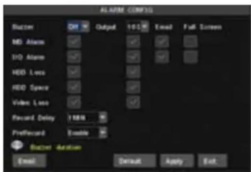
Click [Main Menu→Device → Alarm] to enter into [Alarm setup] menu to setup Alarm warnings (shown as Picture 5-25a). Click [Alarm Config] on the bottom of the [Alarm setup] screen to enter into the interface shown as Picture 5-25(b). Now you are allowed to set detailed alarm parameters.
I/O STATUS: Options include NO (Normal-open), NC (Normal-close) and OFF. Set to "Normal-open" if you use external sensor alarms that are normally open, Set to "Normal-close" if you use external sensor alarms that are normally closed, set to "off" if you are not going to use external sensor alarms. You can use the DVRs internal motion detection to record when motion is detected; you do not external sensors to record on motion detection.
text_image
ALARM SETUP
Channel
OK
USB Status
NO
Copy To
A/B
Copy
Select Channel to
Alarm Config
Default
Apply
Exit
Picture 5-25 (a)
text_image
ALAPRE CONFIG
Bucket
Output
100%
Email
Full Screen
MD Atom
100 Atom
HDD Loco
HDD Space
Video Loco
Record Delay 100%
Prefrecord Enable
Bucket Action
Email
Default
Apply
Exit
Picture 5-25 (b)
HDD LOSS: Options are On and Off. If you select On there will be a buzzer sound and "H" sign on screen when HDD is not detected or not formatted; on the contrary, if you close the function, there is only "H" sign to indicate HDD not found, but no alarm sound when HDD not found or not formatted.
HDD SPACE: Options are On and Off. When the alarm function is on, there are alarm sounds when the HDD is running out of space; when the function is off, there are no alarm sounds.
VIDEO LOSS: Options are On and Off. When the function is on, system will issue alarm sound and display video loss on the preview interface; when the function is off, system will have no alarm sound, but the preview interface will display video loss.
ALARM MANAGE: Alarm Output (0s,10s,20s,40s,60s)、Buzzer time (0s,10s,20,40s,60s) and alarm duration time (0s, 30s, 1minute, 2minute, 5minute)。
Pre-record time: you can set how long record will last before alarm occurs (Off, on).
Full screen Alarm: The function is defaulted to "On". When the motion detection or external alarm is triggered, the corresponding channel will be displayed on the full screen mode.
Email: The option allows you set the alarm images is issued to a specified email or not.
You could freely select buzzer alarm or not and alarm output time for all the alarm types, and for the MD alarm and I/O status alarm you could set email and full screen reminder.
| Alarm Type Function |
| Video Loss | Sends alarm when DVR can’t receive video signal (such as camera damage, cable broken or damaged or power supply malfunction). |
| Motion Detection | When an object moves into motion detection area, alarm will be triggered. You can adjust sensitivity level to suit the needs of your actual application environment. |
| I/O Status | System can convert alarm signal triggered by external sensor into signal identified by system. |
| HDD loss | When Hard Drive is not detected (HDD damage, power supply malfunction), or HDD auto-overwrite is off, and free space is not enough, an alarm will be triggered. |
EMAIL Setup
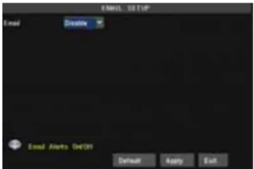
Click [Email Set] to enter into the interface shown as Picture 5-26.
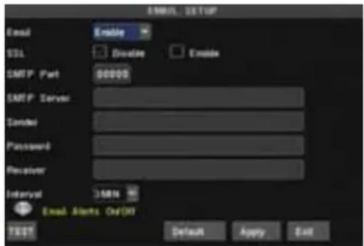
On the [EMAIL] screen, when Enabling [Email] option, you can set its parameters shown as Picture 5-27.
SSL: is a security link transport protocol. You can encrypt your communication info (including your email) using SSL to prevent hackers from monitoring your email or communication info and even your password.
Generally Gmail.com server set SSL to [On], and other mail server to [Off]. If your setting is still not right, please contact the web site where you have applied for your email box to get SMTP port and SSL of mail box.
SMTP Port: indicates sender port of SMTP server. Generally the SMTP port value is 25, but there are exceptions, for example, SMTP port of G-mail server should be 465.
text_image
EMAIL SETUP
Email
Welcome
Email Alerts On'Don
Default Apply Exit
Picture 5-26 Picture 5-27
text_image
EMAIL SETUP
Email Enable
SSL Divide Enable
SMTP Part 90000
SMTP Server
Sender
Password
Receiver
Interval 348N
Email Alerts OutDO
TEST Default Apply Exit
SMTP server: indicates server address you use.
Sender email: indicates sender's email address. The email address should be consistent with the server you use. That is to say, when you use email address – aaa@gmail.com, the according server should be smtp.gmail.com.
Receiver address: indicates receiver's email address. The email address is used to receive image transmitted from motion detection alarm of DVR. Please clear the images you have received as soon as possible to avoid overloading your email account.
Email Test: Click the button to check your SMTP port, server, sender and receiver address. Once the parameters are wrong, system will return misinformation back to inform user modified. Before you perform function, please make sure your email server support SMTP and SSL service.
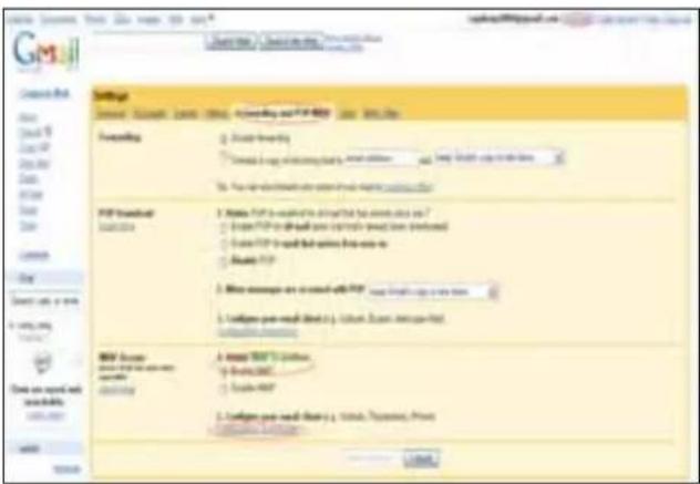
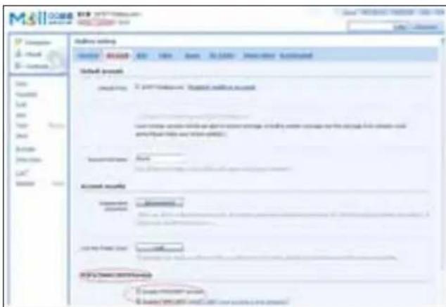
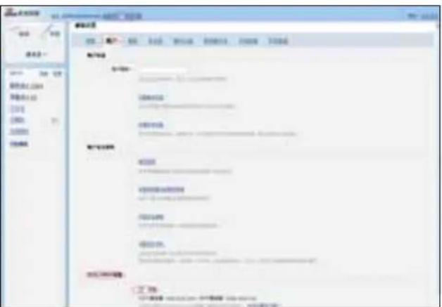
Note: Sender email is required to enable IMAP/POP3/SMTP function (details please refer to Picture 5-28 & Picture 5-29 (a & b), which show IMAP/POP3/SMTP Enable setting function for Gmail, QQ and SINA mail). Login your GMAIL ID and turn to Settings page. Find out Forwarding and POP/IMAP option and then tick-select [enable IMAP] option.
text_image
GMS
Settings
General: Download - General: Download and PDF-Export - User: Web Date
Forwarding:
□ Default Forwarding
□ Default to map the following key: Email address and http://www.gms.org/10.0000000000000000000000000000000000000000000000000000000000000000000000000000000000000000000000000000
PDF download
1. Write PDF to download the link between the email address and web page.
2. Use PDF to add the link between the email address and web page.
3. Use PDF to add the link between the email address and web page.
4. Use PDF to add the link between the email address and web page.
5. Write messages on a social media PDF: www.fund123.com
6. Include post-mail (http://fund123.com) and post-mail (http://fund123.com)
7. Include post-mail (http://fund123.com) and post-mail (http://fund123.com)
8. Include post-mail (http://fund123.com) and post-mail (http://fund123.com)
9. Include post-mail (http://fund123.com) and post-mail (http://fund123.com)
10. Include post-mail (http://fund123.com) and post-mail (http://fund123.com)
11. Include post-mail (http://fund123.com) and post-mail (http://fund123.com)
12. Include post-mail (http://fund123.com) and post-mail (http://fund123.com)
13. Include post-mail (http://fund123.com) and post-mail (http://fund123.com)
14. Include post-mail (http://fund123.com) and post-mail (http://fund123.com)
15. Include post-mail (http://fund123.com) and post-mail (http://fund123.com)
16. Include post-mail (http://fund123.com) and post-mail (http://fund123.com)
17. Include post-mail (http://fund123.com) and post-mail (http://fund123.com)
18. Include post-mail (http://fund123.com) and post-mail (http://fund123.com)
19. Include post-mail (http://fund123.com) and post-mail (http://fund123.com)
20. Include post-mail (http://fund123.com) and post-mail (http://fund123.com)
21. Include post-mail (http://fund123.com) and post-mail (http://fund123.com)
22. Include post-mail (http://fund123.com) and post-mail (http://fund123.com)
23. Include post-mail (http://fund123.com) and post-mail (http://fund123.com)
24. Include post-mail (http://fund123.com) and post-mail (http://fund123.com)
25. Include post-mail (http://fund123.com) and post-mail (http://fund123.com)
26. Include post-mail (http://fund123.com) and post-mail (http://fund123.com)
27. Include post-mail (http://fund123.com) and post-mail (http://fund123.com)
28. Include post-mail (http://fund123.com) and post-mail (http://fund123.com)
29. Include post-mail (http://fund123.com) and post-mail (http://fund123.com)
30. Include post-mail (http://fund123.com) and post-mail (http://fund123.com)
31. Include post-mail (http://fund123.com) and post-mail (http://fund123.com)
32. Include post-mail (http://fund123.com) and post-mail (http://fund123.com)
33. Include post-mail (http://fund123.com) and post-mail (http://fund123.com)
34. Include post-mail (http://fund123.com) and post-mail (http://fund123.com)
35. Include post-mail (http://fund123.com) and post-mail (http://fund123.com)
36. Include post-mail (http://fund123.com) and post-mail (http://fund123.com)
37. Include post-mail (http://fund123.com) and post-mail (http://fund123.com)
38. Include post-mail (http://fund123.com) and post-mail (http://fund123.com)
39. Include post-mail (http://fund123.com) and post-mail (http://fund123.com)
40. Include post-mail (http://fund123.com) and post-mail (http://fund123.com)
41. Include post-mail (http://fund123.com) and post-mail (http://fund123.com)
42. Include post-mail (http://fund123.com) and post-mail (http://fund123.com)
43. Include post-mail (http://fund123.com) and post-mail (http://fund123.com)
44. Include post-mail (http://fund123.com) and post-mail (http://fund123.com)
45. Include post-mail (http://fund123.com) and post-mail (http://fund123.com)
46. Include post-mail (http://fund123.com) and post-mail (http://fund123.com)
47. Include post-mail (http://fund123.com) and post-mail (http://fund123.com)
48. Include post-mail (http://fund123.com) and post-mail (http://fund123.com)
49. Include post-mail (http://fund123.com) and post-mail (http://fund123.com)
50. Include post-mail (http://fund123.com) and post-mail (http://fund123.com)
51. Include post-mail (http://fund123.com) and post-mail (http://fund123.com)
52. Include post-mail (http://fund123.com) and post-mail (http://fund123.com)
53. Include post-mail (http://fund123.com) and post-mail (http://fund123.com)
54. Include post-mail (http://fund123.com) and post-mail (http://fund123.com)
55. Include post-mail (http://fund123.com) and post-mail (http://fund123.com)
56. Include post-mail (http://fund123.com) and post-mail (http://fund123.com)
57. Include post-mail (http://fund123.com) and post-mail (http://fund123.com)
58. Include post-mail (http://fund123.com) and post-mail (http://fund123.com)
59. Include post-mail (http://fund123.com) and post-mail (http://fund123.com)
60. Include post-mail (http://fund123.com) and post-mail (http://fund123.com)
61. Include post-mail (http://fund123.com) and post-mail (http://fund123.com)
62. Include post-mail (http://fund123.com) and post-mail (http://fund123.com)
63. Include post-mail (http://fund123.com) and post-mail (http://fund123.com)
64. Include post-mail (http://fund123.com) and post-mail (http://fund123.com)
65. Include post-mail (http://fund123.com) and post-mail (http://fund123.com)
66. Include post-mail (http://fund123.com) and post-mail (http://fund123.com)
67. Include post-mail (http://fund123.com) and post-mail (http://fund123.com)
68. Include post-mail (http://fund123.com) and post-mail (http://fund123.com)
69. Include post-mail (http://fund123.com) and post-mail (http://fund123.com)
70. Include post-mail (http://fund123.com) and post-mail (http://fund123.com)
71. Include post-mail (http://fund123.com) and post-mail (http://fund123.com)
72. Include post-mail (http://fund123.com) and post-mail (http://fund123.com)
73. Include post-mail (http://fund123.com) and post-mail (http://fund123.com)
74. Include post-mail (http://fund123.com) and post-mail (http://fund123.com)
75. Include post-mail (http://fund123.com) and post-mail (http://fund123.com)
76. Include post-mail (http://fund123.com) and post-mail (http://fund123.com)
77. Include post-mail (http://fund123.com) and post-mail (http://fund123.com)
78. Include post-mail (http://fund123.com) and post-mail (http://fund123.com)
79. Include pre-post mail
80. Include pre-post mail
81. Include pre-post mail
82. Include pre-post mail
83. Include pre-post mail
84. Include pre-post mail
85. Include pre-post mail
86. Include pre-post mail
87. Include pre-post mail
88. Include pre-post mail
89. Include pre-post mail
90. Include pre-post mail
91. Include pre-post mail
92. Include pre-post mail
93. Include pre-post mail
94. Include pre-post mail
95. Include pre-post mail
96. Include pre-post mail
97. Include pre-post mail
98. Include pre-post mail
99. Include pre-post mail
* * * * * * * * * * * * * * * * * * * * * * * * * * * * * * * * * * * * * * * * * * * * * * * * * * * |
* * * * * * * * * * * * * * * * * * * * * * * * * * * * * * * * * * * * * * * * * * * * * * * * |
* |
*
*
*
*
*
*
*
*
*
*
*
*
*
*
*
*
*
*
*
*
*
*
*
*
*
*
*
*
*
*
*
*
*
*
*
*
*
*
*
*
*
*
*
*
*
*
*
*
*
*
[ ]
[ ]
[ ]
[ ]
[ ]
[ ]
[ ]
[ ]
[ ]
[ ]
[ ]
[ ]
[ ]
[ ]
[ ]
[ ]
[ ]
[ ]
[ ]
[ ]
[ ]
[ ]
[ ]
[ ]
[ ]
[ ]
[ ]
[ ]
[ ]
[ ]
[ ]
[ ]
[ ]
[ ]
[ ]
[ ]
[ ]
[ ]
[ ]
[ ]
[ ]
[ ]
[ ]
[ ]
[ ]
[ ]
[ ]
[ ]
[ ]
[ ]
[ ]
[ ]
[ ]
[ ]
[ ]
[ ]
[ ]
[ ]
[ ]
[ ]
[ ]
[ ]
[ ]
[ ]
[ ]
[ ]
[ ]
[ ]
+
Picture 5-28
text_image
Mail
Email: mail@mail.com
Mail: mail@mail.com
Address setting
Email: mail@mail.com
Email: mail@mail.com
Default options
emailkey: 2.4371900000, Default email account
User name: www.mail.org or your email account, including email account on the right link between us and your email account with other accounts.
Access details:
Email:
Account security:
Password: www.mail.org
Email name: www.mail.org
Email name: www.mail.org
Email name: www.mail.org
Email name: www.mail.org
Email name: www.mail.org
Email name: www.mail.org
Email name: www.mail.org
Email name: www.mail.org
Email name: www.mail.org
Email name: www.mail.org
Email name: www.mail.org
Email name: www.mail.org
Email name: www.mail.org
Email name: www.mail.org
Email name:www.mail.org
Email name: www.mail.org
Email name: www.mail.org
Email name: www.mail.org
Email name: www.mail.org
Email name: www.mail.org
Email name: www.mail.org
Email name: www.mail.org
Email name: www.mail.org
Email name: www.mail.org
Email name: www.mail.org
Email name: www.mail.org
Email name: www.mail.org
Email name: www.mail.org
Email name: www.mail.com
Picture 5-29a
text_image
Scanned screenshot of a Chinese web interface showing a form with fields for account, email, and email address.
Picture 5-29b
If you can't receive email alarm information successfully, please check below points:
▶ DVR connection is normal or not;
The receiver and sender email support SMTP protocols or not;
➢ Emails account setting is correct or not;
➢ Email alarm parameters configuration is right or not;
➢ DVR is on the status of I/O alarm or Motion detection or not.
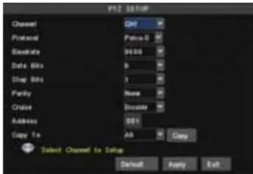
5.3.6.3 PTZ setup
Enter into [Main menu→Device→PTZ Setup] to select the channel you desire to control and set PTZ protocol (Pelco-D or Pelco-P), Baud Rate (1200, 2400, 4800, 9600), Data bit (8, 7, 6, 5), Stop bit (1, 2), Parity Check (None, Odd, Even, Mark, Space), Address Code and Cruise status respectively.
text_image
F12 031UP
Channel QNT
Protocol Polka-0
Binary Data Bits 9
Drop Bits 1
Parity None
Order Discolor
Address 001
Copy To All Copy
Select Channel to Setup
Default Apply Exit
text_image
M001.0
User Name admin
Password ********
Service Port 18004
Default Apply Exit
Picture5-31 Picture5-30
5.3.6.4 Mobile setup
The DVR is currently compatible with mobile phones running Andriod, Windows Mobile, Symbian, Iphone and Blackberry operating systems on 3G networks. Details access methods please refer to separate Mobile phone Access Instructions.
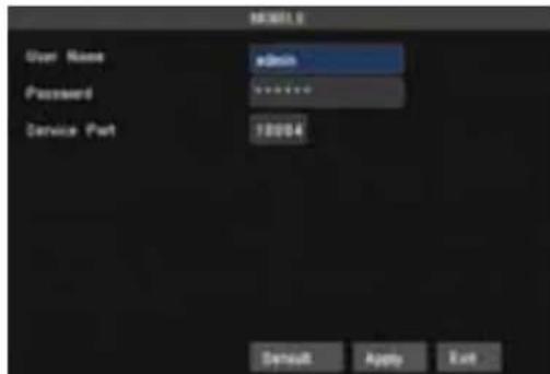
Click [Main menu→Device→Mobile] to enter into [Mobile] menu shown as Picture 5-31.
- User Name: indicate user name of DVR, and system supports up to 15 characters.
- User password: indicate user password of DVR, and system supports up to 15 characters.
● Server port: Mobile monitoring port. Setting value is adjustable between 1024 and 65535.
Explanation: Please connect DVR to Internet before setting DVR port number and the server port no is not equal to network menus.
5.3.6.5 Motion Detection
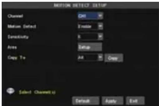
Click [Main menu→Device→Motion] to enter into the [Motion Detection] menu shown as Picture 5-32.
The [Motion detection] Menu has three sections, including Channel Status, Sensitivity and Motion area.
Channel: This option allows you enable motion detection on any channel.
➢ SENSITIVITY: This option allows you to set sensitivity level of motion detection from higher to low with 8 being the most sensitive.
MD AREA: This option allows you select the area you want to be sensitive to motion.
➢ Copy to: allow you copy current channel parameters to any other channel or all channels.
text_image
MOTION DETECT SETUP
Channel Ctrl
Motion Detect Emotion
Connectivity 8
Area Setup
Crop To Alt Copy
Select Channel(s) Default Apply Exit
Picture 5-32
natural_image
Solid red background with a small white square at the center (no text or symbols)
Picture 5-33
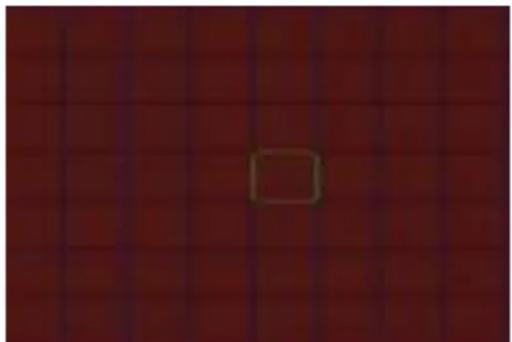
Each channel is separated into 15X12 grids for PAL system and 15X10 grids for NTSC system. When any object moves into the motion detection area, and the area where the object is located is displayed in red recording will be triggered. In the semi-transparent area the motion detection is off.
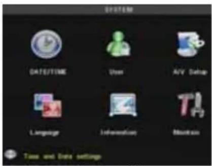
5.3.7 System
menu include the below sub-menu-Time set, User password, A/V set, Language, System Information and system maintain.
After entering into menu, you are allowed to set time/date, password, language and A/V, check system information and perform system maintenance.
text_image
SYSTEM
DATE/TIME
User
AVV Setup
Language
Information
Monitor
Task and Data settings
Picture 5-34
text_image
TIME SETTINGS
Data
00:00:00:11
Data Format
00:00:00:11
Time
17:28:17
Time Format
24:44:44
Time Zone
GRT+03 60W
MTP
Enable
MTP ORDER
Home SWISSUE.COM
UPDATE NOW
SET Setting
SET Setting
Default
Apply
Exit
Picture 5-35
text_image
BST SETTINGS
Daylight Saving Time
Time Offset
Daylight Saving Time Block
Stock Time: 800
The End
20%
82.69.69
End Time: 800
The End
20%
82.69.69
Default
Apply
Exit
Picture 5-36
5.3.7.1 Time Set
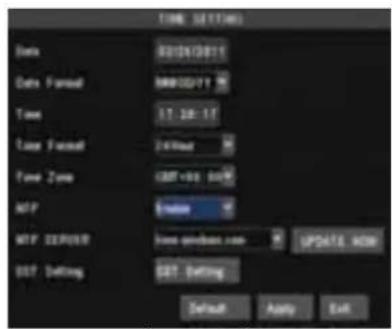
Click [Main menu→ system] and enter into the time set interface shown as Picture 5-35. Now you can adjust system date/time, date/time format and time zone.
NTP: the model provides NTP service. When NTP function is set to , select relative NTP server (include: time.windows.com; time.nist.gov or pool.ntp.org) and click , and system will check and adjust system time at every 23:50:00pm and/or each restart
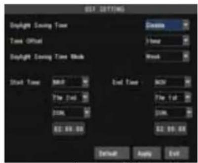
DST: Click to set DST (day saving time) status and mode shown as Picture 5-36.
5.3.7.2 Password
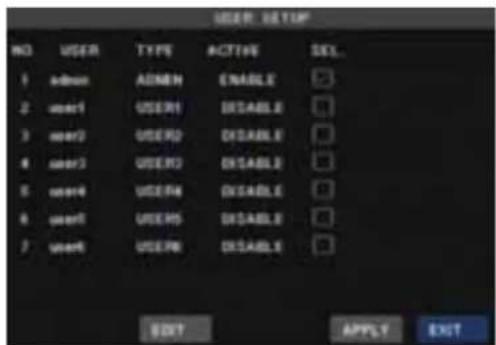
Click [Main menu→System→Password] to enter into [user manage] interface shown as Picture 5-37.
text_image
USER: HKEYF
NO USER TYPE ACTIVE SEL.
1 admin ADMIN ENABLE
2 user1 USER1 DISABLE
3 user2 USER2 DISABLE
4 user3 USER3 DISABLE
5 user4 USER4 DISABLE
6 user5 USER5 DISABLE
7 user6 USER6 DISABLE
BOOT APPLY EXIT
Picture 5-37 Picture 5-39
text_image
USER PASSWORD SETUP
USER NAME admin
USER NAME
PASSWORD ENABLE Disable
PASSWORD
COMFORM
DEFAULT APPLY EXIT
Picture 5-38
text_image
USER AUTHORETS
USER NAME app1
DISPLAY MOBILE
RECORD MOTION
NETWORK SATELLINE
VIDEO SEARCH SCHEDULES
MOD MANAGEMENT AVV SETUP
ALARM LANGUAGE
PTZ SETUP MAINTAIN
PTZ CONTROL
ALL CLEAR APPLY STOP
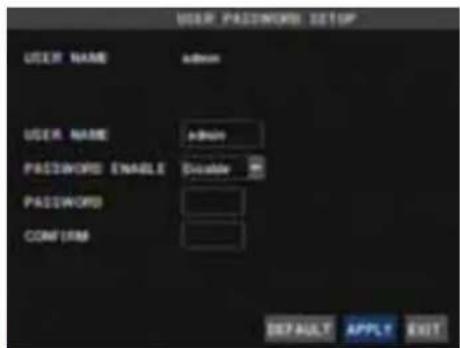
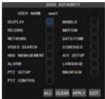
Click [Edit user] to enter into password set interface shown as Picture 5-38.
You can setup a user password and administrator password respectively shown as Picture 5-39. The password consist of numbers 0\~9 and supports up to 6 characters.
The password defaulted by system is 123456.
5.3.7.3 Video/Audio Setup
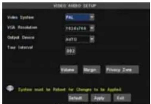
Click [Main Menu→System→Video/Audio] to setup Video and Audio parameters shown as Picture 5-39 (a).
Video System: allow you set Camera system (PAL, NTSC).
VGA Resolution: include four options - 1280×1024、1024×768、800×600 and 1440×900.
➢ OSD Device: allow you select video output device, options include , and .
: When set to and connected to VGA and monitor simultaneously, video output will appear in VGA screen; and whatever connected to VGA or Monitor, video images will automatically appear in the device connected.
text_image
VIDEO AUDIO SETUP
Video System
PAL
VIA Resolution
1034x746
Output Device
Auto
Taur Interval
802
Volumes
Merge
Privacy Zone
System must be Rated for Changes to be Applied
Default
Apply
Exit
Picture 5-40
text_image
MARGIN SETUP
Left Margin —— 5
Right Margin —— 6
Top Margin —— 5
Bottom Margin —— 6
Default Apply Exit
Picture 5-41
: When set to , video output will appear in the monitor's screen.
: When set to , video output will appear in the VGA's screen.
User can hold pressing [Rew] button for 5 second on the front panel to convert output device quickly.
➢ Poll time: allow you select sequence time between from 5s and 300s.
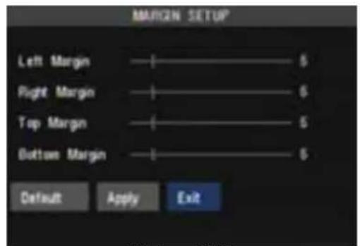
Click the [Volume] and/or [Margin] options on the right-bottom corner of the Video/Audio screen to adjust the volume and/or margin respectively. Details please kindly find the Picture 5-41.
And you are allowed to set