RM10MSF - Uncategorized Superrollo - Free user manual and instructions
Find the device manual for free RM10MSF Superrollo in PDF.


User questions about RM10MSF Superrollo
0 question about this device. Answer the ones you know or ask your own.
Ask a new question about this device
Download the instructions for your Uncategorized in PDF format for free! Find your manual RM10MSF - Superrollo and take your electronic device back in hand. On this page are published all the documents necessary for the use of your device. RM10MSF by Superrollo.
USER MANUAL RM10MSF Superrollo
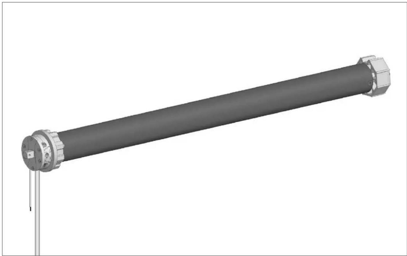
Rohrmotor RM10MSF/RM10MMF/RM20MMF/RM30MMF
natural_image
3D rendering of a cylindrical mechanical component with flanges and a central shaft, shown without any text or symbols.BA20806-2A(11.2010)
Art.-Nr.: SR20806, SR20815, SR20825, SR20835
D Montage- und Bedienungsanleitung ...... Seite 3
GB Installation and operating instructions ...... Page 16
E Instrucciones de montaje y uso.... Página 29
P Manual de montagem e instruções a partir.... Página 42
PL Instrukcja montażu i użytkowania.... Strona 55
Rohrmotor RM10MSF/RM10MMF/RM20MMF/RM30MMF
Inhaltsverzeichnis
Übersicht....3
Vorwort 4
text_image
Technical diagram of a mechanical device with numbered components and labeled parts① Gegenlager*
⑧ Antriebskopf
② Kugellager*
⑨ Antriebslager
③ Walzenkapsel*
⑩ Fernbedienung
text_image
Exploded view diagram of a mechanical assembly with labeled components and partstext_image
D P Y X 1 2 3ACHTUNG
text_image
Technical diagram of a mechanical assembly with numbered components and an arrow indicating directiontext_image
Technical diagram showing three labeled mechanical components (1, 2, 3) with directional arrows indicating assembly or movement.ACHTUNG
natural_image
Close-up of a mechanical component with arrows indicating direction, no visible text or symbolsnatural_image
Mechanical assembly diagram showing a rotating component with two circular features and an arrow indicating motion (no text or symbols)
text_image
Technical diagram of a mechanical component with numbered parts and an arrow indicating assembly or transformation.text_image
Technical diagram of a mechanical assembly with labeled parts 1 and 2, showing a bolted joint and mounting bracket.natural_image
Close-up of a mechanical component with a knob and adjustment arrow (no text or symbols)natural_image
Mechanical assembly diagram showing a pipe connection with a spring and drop drop (no text or symbols)text_image
Diagram of a mobile phone rear panel with four labeled components pointing to the screen interface.① Taste AUF
③ Taste AB
② Taste STOPP
④ Kontroll-LED
text_image
Technical diagram showing a mechanical assembly with labeled parts 1 and 2, and directional arrow indicating motion or force.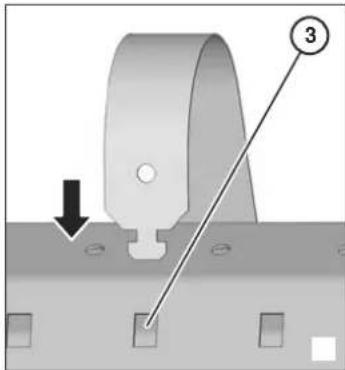
text_image
Technical diagram showing a mechanical component with labeled parts and directional arrowtext_image
Technical diagram showing a mechanical assembly with labeled parts and a directional arrow indicating rotation or movement.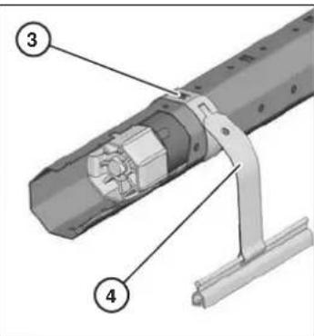
text_image
Technical diagram of a mechanical assembly with numbered components labeled 3 and 4text_image
Diagram showing mechanical or electrical component with labeled parts and directional arrows indicating movement or flow.natural_image
Mechanical assembly diagram showing a cylindrical component with a rotating shaft and mounting holes (no text or symbols)natural_image
Mechanical assembly diagram showing a cylindrical component with a rotating shaft and mounting holes (no text or symbols)Tubular motor RM10MSF/RM10MMF/RM20MMF/RM30MMF
Table of contents
Overview 16
Preface 17
Basic safety instructions....17
Description of the device....18
Installing the device 19
Starting up the device....22
Rectifying malfunctions....24
Dismantling the device 27
Disposing of the device 27
Technical data 28
Accessories 28
Warranty conditions....28
EU declaration of conformity 28
Overview
text_image
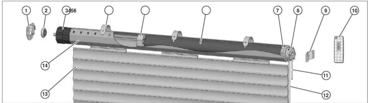
Technical diagram of a mechanical device with numbered components and labeled parts① Counter bearing*
② Ball bearing*
③ Roller capsule*
④ Securing spring*
⑤ Driver
⑥ Tubular motor
⑦ Adapter
⑧ Driving head
⑨ Drive bearing
⑩ Remote control
⑪ Motor antenna
⑫ Motor cable
⑬ Roller shutter curtain*
⑭ Winding shaft*
The figure shows the tubular motor in its installation situation. The parts marked * do not form part of the scope of delivery.
Preface
These operating instructions describe the installation, the electrical connection and the operation of the RM10MSF/RM10MMF/RM20MMF/RM30MMF electronic tubular motors. Read through these operating instructions carefully prior to installation and initial operation and, in particular, follow the safety instructions!
These instructions help you to make
■ proper,
■ safe and
■ advantageous
use of the RM10MSF/RM10MMF/RM20MMF/RM30MMF electronic tubular motors, briefly referred to as the motor.
These instructions describe the installation and use of the tubular motor with the necessary superrollo accessories. The term device is used in these instructions for the tubular motor in combination with the accessories.
These operating instructions are intended for the following persons:
■ Persons who install this device,
■ Persons who connect this device,
■ Persons who operate this device,
■ Persons who maintain this device or
■ Persons who dispose of this device.
Each of these persons must have read and understood the entire content of these operating instructions.
All activities on and with this device may only be carried out to the extent that they are described in these operating instructions.
The warranty expires in the event of damage caused by non-observance of these instructions. superrollo accepts no liability for subsequent damage.
Availability
These operating instructions form part of the product. Always store these operating instructions in the vicinity of the device. Pass the operating instructions on if you sell the device or forward it an any other manner.
Structural features of these operating instructions
Defined structural features are assigned to the various elements within the operating instructions. You can therefore easily determine the type of text which this involves:
Normal text,
Cross references,
DIRECTIONS OF ROTATION OF THE ADJUSTER SCREWS,
■ Lists or
➢ Action steps.

Notices with this symbol contain information on economical use of the device.
Basic safety instructions
Proper use
The device is used exclusively for raising and lowering smoothly running roller shutters and awnings.
Avoiding electric shocks
■ Have connection to the mains and all work on the voltage supply carried out by a qualified, trained specialist electrician only.
■ Only connect the device to a 230 V\~50 Hz current connection which is fused in the building.
- Carry out all installation and connection work in voltage-free condition.
■ If cables or electrical facilities which are not required are present at the installation location, remove these or decommission them.
■ Before installing the motor, remove all cables and electrical facilities which are not required for operation or decommission them.
■ Route the motor cable internally in the empty tube, observing the local electrical regulations, up to the junction box.
■ In the event of malfunctions, disconnect the device from the mains power supply.
■ Before opening the roller shutter box, disconnect the device from the mains power supply.
■ Prior to cleaning work on the roller shutter, disconnect the device from the mains power supply.
■ Do not store the motor together with acid, alkaline substances or dirty or eroded materials.
■ Make sure that the device does not become moist and is not located in a vapourous environment during transportation, storage and use.
■ Do not use the motor for garage doors in public buildings.
■ Do not touch the mains power cable with moist hands.
■ Never unscrew the device's housing.
■ Never use a defective device. If your device is defective, contact the customer service.
■ In the event of use in damp rooms, observe DIN VDE 0100, Parts 701 and 702.
Avoiding risk of injury
■ Make sure that the roller shutter box is closed when the device is in operation.
■ Make sure that no persons are located beneath the roller shutter when the roller shutter is being lowered.
■ Make sure that children do not play with the remote control.
■ Make sure that no persons can be injured by the roller shutter slipping down during installation work.
■ Lower the roller shutter completely prior to installation work or support the roller shutter.
■ Only use the device with roller shutters whose weight is appropriate for the tubular motor. Information on this can be found in the section entitled Permissible roller shutter areas and weights from page 19.
■ Regularly check the device for imbalance, damage and worn cables and springs.
■ Only use the device in flawless condition.
■ Do not start the motor too frequently, and do not overload it.
■ Only turn the adjustment knob or the drive bushing in operating mode.
■ Use only genuine replacement parts and accessories from superrollo. Information on this can be found in the chapter entitled Accessories from page 28
■ Make sure that repairs on the device are only carried out by the superrollo customer service.
In particular, observe DIN 12045 - additional protective facilities and terminations for facades and wall openings which are equipped with windows and French windows.
Avoiding being locked out
■ Make sure that you are located inside the building when a door's roller shutter is automatically closed.
Avoiding damage
■ Use the device in dry rooms only.
■ Only connect the device to a 230 V\~50 Hz current connection which is fused in the building.
■ Use the device with smoothly running roller shutters only.
■ Use only genuine replacement parts and accessories from superrollo.
Structural features of the information on dangers
The following categories of information on dangers are contained in these operating instructions:

DANGER
Notices containing the word DANGER warn of a hazardous situation which leads to death or severe injuries.

WARNING
Notices containing the word WARNING warn of a hazardous situation which may possibly lead to death or severe injuries.

CAUTION
Notices containing the word CAUTION warn of a situation which leads to slight or moderate injuries.
Structural features of notices regarding material and environmental damage
ATTENTION
These notices warn of a situation which leads to material or environmental damage.
Description of the device
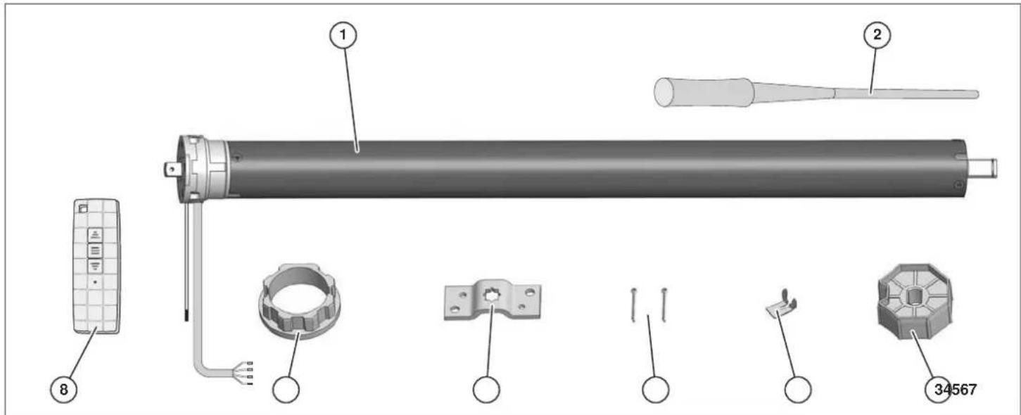
Scope of delivery
text_image
Exploded view diagram of a mechanical assembly with labeled parts including motor, gear, and adjustment tools① Tubular motor
② Adjustment tool
③ Driver
⑦
Adapter
④ Securing clip
⑤ 2 x cotter pin
⑥ Drive bearing
⑧ Remote control
Functions
The device can be used to open and close roller shutters and awnings.
In order to carry out these functions, the tubular motor must be installed together with the following superrollo accessories in the roller shutter box:
■ Winding shaft
■ Roller capsule
■ Ball bearing
■ Counter bearing
■ Securing springs.
Information on the superrollo accessories can be found in the chapter entitled Accessories from page 28.
Permissible roller shutter areas and weights
The following table shows the roller shutter area permissible for the relevant motor depending on the profile weight. The maximum roller shutter weight is additionally listed.
| Article No. Max. roller shutter area (m2) | Max. roller shutter weight (kg) | ||
| RM10MSF 3.5 2.5 20 | |||
| RM10MMF 3.5 2.0 20 | |||
| RM20MMF 6.5 4.0 40 | |||
| RM30MMF 10 6.0 60 | |||
➢ Make sure that the maximum roller shutter area and the maximum roller shutter weight are not exceeded.
Safety functions
The tubular motor is designed for short-term operation (four minutes). In order to avoid damage to the motor, the motor shuts off automatically on exceeding this period of time or in the event of frequent switching.
Safety shut-off may be attributable to various causes. Before the device is started up again, you may have to rectify the cause. Information on possible causes and their rectification can be found in the chapter entitled Rectifying malfunctions from page 24.
▶ Rectify the cause if necessary.
➢ Allow the motor to cool for approx. 20 minutes.
If function remains impossible following these measures, contact the superrollo customer service.
Installing the device
Prior to installation
The following prerequisites must be met in order to be able to install the device:
■ The roller shutter box cover must be easily accessible and removable.
■ A 230 V\~50 Hz current connection with an isolating facility (fuse) in the building must be available at the installation location.
■ The weight of the roller shutter must be appropriate for the tubular motor. Information on the permissible roller shutter weight can be found in the section entitled Permissible roller shutter areas and weights from page 19.
■ The required superrollo accessories must be available. Information on the superrollo accessories can be found in the chapter entitled Accessories from page 28.
▶ Check the scope of delivery for damage.
➢ Do not operate the device if you discover damage on the device.
If damage is discovered on the device, contact the superrollo customer service.
Required tools
The following tools and fasteners are required to install the device:
■ Pencil
■ Spirit level
■ Metal cutting saw
■ File
Drill
■ 8 mm masonry drill bit
■ 8 mm plugs
■ Screws
■ Phillips screwdriver
■ Enclosed adjustment tool.
■ Folding meter rule or measuring tape
Installing the bearings
The motor's driving head can be installed on the right- or left-hand side of the roller shutter box. Installation on the right-hand side is described in these instructions.
The following points must be observed when installing the bearings:
■ The bearings must be aligned horizontally.
■ The roller shutter must be able to run vertically in the guide rail.
■ The roller shutter curtain must have sufficient space on all sides when rolled up in the roller shutter box.
■ The tubular motor adjuster screws must be easily accessible following installation.
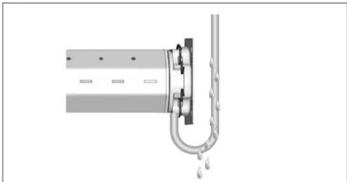
In order to allow water to drip off, the motor cable must be routed downwards in a loop directly before the motor.
In order to determine bearing position P in the roller shutter box, measure and calculate the following dimensions:
D Diameter of the rolled up roller shutter
X D/2 Distance between the bearing position P and the centre of the guide rail (3)
Y >X Distance between the bearing position P and the bottom of the roller shutter box. So that the roller shutter has sufficient clearance, Y must be greater than X.
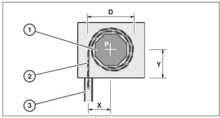
text_image
D P Y X ① ② ③ATTENTION
Damage to the tubular motor due to the roller shutter being rolled up slanted.
Make sure that the device is installed horizontally.
Using a pencil, mark the bearing positions P on the right and left inner sides of the roller shutter box.
Make sure that the marks are aligned horizontally.
➢ Hold the bearings centrally on the marks.
Mark the holes to be drilled using a pencil.
Drill the holes using an 8 mm drill bit.
Insert the plugs.
Screw the bearings down tightly.
Sawing the winding shaft to length
In order to determine the length L of the winding shaft, measure and calculate the following dimensions:
A Clear width of the roller shutter box
B b1+b2+b3
b1 Depth of the counter bearing
b2 Width of the roller capsule limit stop
b3 1/3 of the roller capsule shaft length
C c1+c2+c3
c1 Depth of the adapter limit stop
c2 Depth of the driving head
c3 Depth of the drive bearing
L A-(B+C)
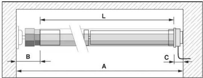
text_image
L B A C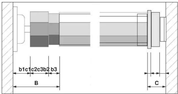
text_image
b1c1c2c3b2 b3 B C➢ Using a pencil, mark the length L on the winding shaft.
➢ Saw the winding shaft to length at a right angle using a metal cutting saw.
➢ Deburr the inner and outer edges using a file.
Assembling the device
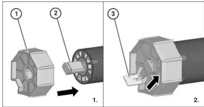
➢ Slide the adapter (1) with the groove over the limit ring (2) spring on the driving head (3).
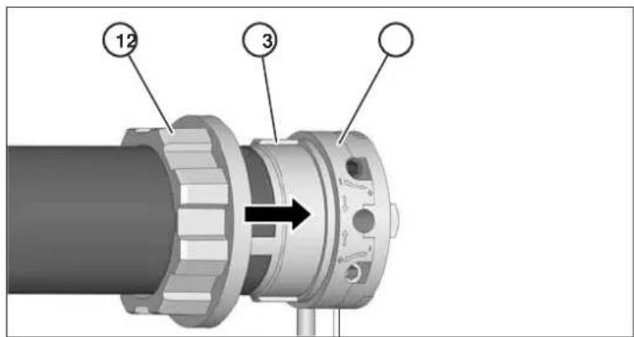
text_image
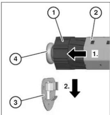
12 3➢ 1. Slide the driver (1) up to the limit stop onto the tubular motor's axle pin (2).
➢ 2. Secure the driver with the enclosed securing clip (3).
text_image
Technical diagram showing three mechanical components with numbered labels and directional arrows indicating assembly or movement.ATTENTION
Damage to the tubular motor due to forcefully driving into the winding shaft.
➢ Never drive the tubular motor into the winding shaft using force.
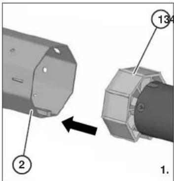
➢ 1. Slide the tubular motor with the driver (1) into the winding shaft (2).
➢ 2. Slide the winding shaft up to the adapter's limit stop (3) on the driving head (4).
➢ Make sure that the adapter does not slip from the driving head limit ring.
text_image
134 ② 1.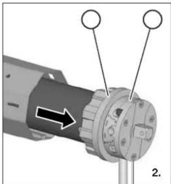
natural_image
Close-up of a mechanical component with three circular features and an arrow indicating direction (no text or symbols)➢ 1. Slide the roller capsule (1) up to the limit stop in the winding shaft (2).
➢ 2. Place the ball bearing (3) onto the roller capsule axle pin (4).
text_image
134 2 1.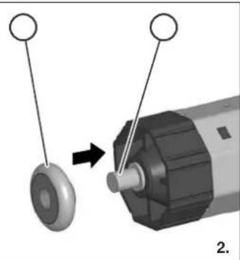
natural_image
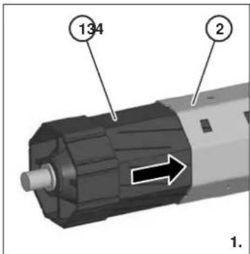
Mechanical assembly diagram showing a rotating component with two circular features and an arrow indicating motion (no text or symbols)In order to be able to install the device in the roller shutter box, the roller capsule must first be inserted up to the limit stop into the winding shaft. It is then pulled out until the device fits precisely into the roller shutter box.
Installing the device in the roller shutter box
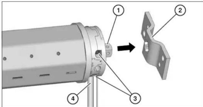
➢ Insert the driving head axle pin (1) into the hole in the drive bearing (2).
➢ Make sure that the adjuster screws (3) are accessible.
➢ Make sure that the motor cable (4) is routed downwards.
text_image
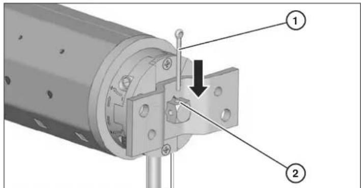
Technical diagram of a mechanical assembly with numbered components and an arrow indicating direction➢ Insert the cotter pin (1) through the securing hole (2) in the axle pin.
text_image
Technical diagram of a mechanical assembly with numbered components and a downward arrow indicating a specific feature.➢ 1. Pull the roller capsule (1) out of the winding shaft (2) until the ball bearing (4) fits into the counter bearing (3).
➢ 2. Insert the ball bearing into the counter bearing.
➢ 3. Screw the winding shaft down tightly on the roller capsule.
text_image
1 2 4 1. 2 3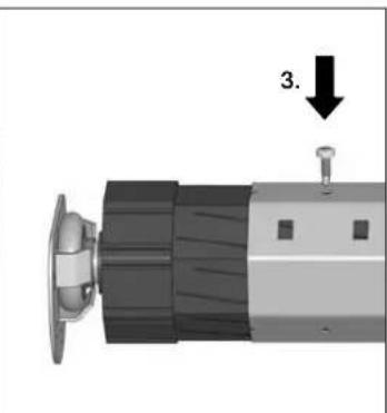
natural_image
Close-up of a mechanical component with a knob and a small pin, no visible text or symbols➢ Make sure that the winding shaft is installed horizontally.
Starting up the device
Before the device can be used, the following steps must be carried out:
■ Connect the motor cable to the mains power supply
■ Insert a 27A-12V battery into the remote control
■ Mount the roller shutter curtain on the winding shaft
■ Set the upper and lower terminal stop point.
Connecting the device
Connection of the tubular motor to the mains power and all work on electrical systems may only be carried out by a certified specialist electrician according to the connection schematics contained in these instructions.

DANGER
Fatal electric shock due to coming into contact with live components.
➢ Do not carry out any connection work on the device when it is connected to the current supply.
➢ Make sure that the device is disconnected from the mains power supply.
ATTENTION
Malfunctions or damage to the motor due to incorrect mains voltage.
➢ Compare the information on the model plate with that of your local mains power supply.
Make sure that the device is only connected to a 230 V \~ 50 Hz mains power supply.
ATTENTION
Short-circuit due to damaged cables.
➢ Make sure that the cable cannot be damaged by moving parts in the roller shutter box.
ATTENTION
Short-circuit due to water in the motor on routing cables incorrectly.
▶ Never route the cable vertically upwards.
▶ Always route the cable in a loop.
Routing the cable in a loop enables the water to drip off (1.).
natural_image
Pure mechanical diagram showing a pipe with a valve and droplet, no text or symbols present➢ Connect the motor cable to the current connection provided for this purpose.
Establishing the radio link
The remote control included in the scope of delivery is used to control the motor's electronics by radio. This chapter provides information on establishing the radio link between the remote control and the motor.
The basic requirement for the remote control function is a charged 27A-12V battery in the battery compartment on the rear side of the remote control.
The indicator LED lights up when a button is pressed.
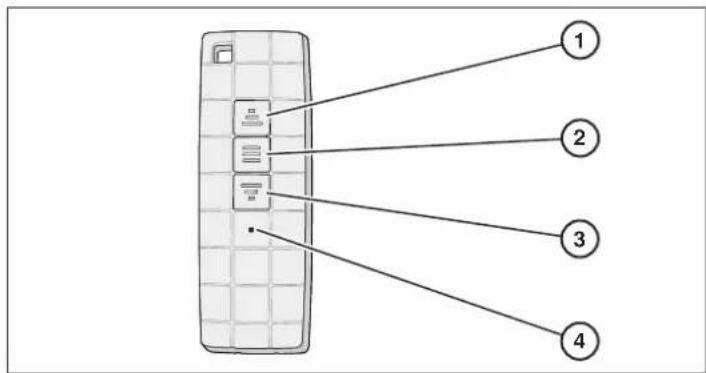
The following overview shows the remote control's controls and displays.
text_image
Diagram of a mobile phone rear panel with four labeled components pointing to the screen interface.① UP button
③ DOWN button
② STOP button
④ Indicator LED
Logging the remote control onto the motor (right-hand motor)
If the motor is installed on the right-hand side of the roller shutter box, the radio link between the motor and the remote control is established in this way.
Switch the motor off.
➢ Wait for approx. 10 seconds.
Switch the motor on again.
A long beep is audibly emitted by the motor.
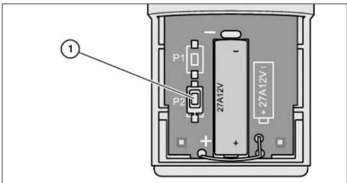
➢ Press button P2 (1) twice; this is located next to the battery compartment on the rear side of the remote control.
text_image
P1 P2 27A12V + + + 27A12V ①➢ Press the UP button once.
Seven short beeps are audibly emitted by the motor.
Logging the remote control onto the motor (left-hand motor)
If the motor is installed on the left-hand side of the roller shutter box, the radio link between the motor and the remote control is established in this way.
Switch the motor off.
➢ Wait for approx. 10 seconds.
Switch the motor on again.
A long beep is audibly emitted by the motor.
➢ Press button P2 (1) twice; this is located next to the battery compartment on the rear side of the remote control.
➢ Press the DOWN button once.
Seven short beeps are audibly emitted by the motor.
Logging a further remote control onto the motor
Proceed as follows to log a further remote control onto the motor:
Switch the motor on.
➢ Wait for approx. 10 seconds.
On the remote control which has already been logged on, press button P2 twice.
On the remote control which is now to be logged on, press button P2 twice.
Five short beeps are audibly emitted by the motor.
Logging the remote control off
Proceed as follows to log a remote control off from the motor:
Switch the motor on.
➢ Wait for approx. 10 seconds.
On the remote control which is to be logged off, press button P2 twice.
➢ Press the STOP button on the remote control.
➢ Press button P2 twice on the remote control.
Four short beeps are audibly emitted by the motor.
Switching the dot-move setting on or off
The dot-move setting can be used to move the roller shutter up or down in sections. To move the roller shutter up or down continuously, the dot-move setting must be deactivated again. Proceed as follows to switch the dot-move setting on or off:
Switch the motor on.
➢ Wait for approx. 10 seconds.
➢ Press button P2 twice on the remote control.
➢ Press the UP button on the remote control.
➢ Press button P2 twice on the remote control.
Three short beeps are audibly emitted by the motor.
Using the remote control
All numbers in brackets refer to the numbers on the remote control overview graphic.
➢ Press the UP button to move the roller shutter up.
➢ Press the STOP button to stop the roller shutter.
➢ Press the DOWN button to move the roller shutter down.
The indicator LED lights up when a button is pressed.
Installing the roller shutter curtain
The following prerequisites must be met in order to be able to install the roller shutter curtain:
■ The roller shutter curtain must lie in the guide rail.
■ The tubular motor must be run all the way down.
ATTENTION
Damage to the tubular motor due to drilling or screwing.
➢ Never drill or screw the winding shaft in the area of the tubular motor.
➢ Use only the holes available in the winding shaft to secure the roller shutter curtain.
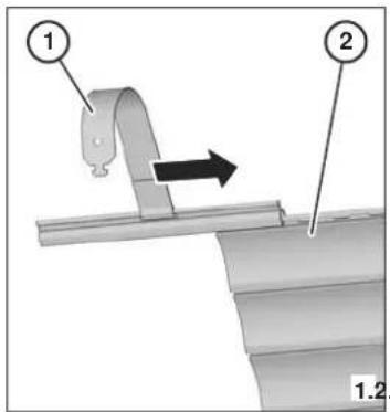
➢ 1. Approx. every 40 cm, slide a securing spring (1) onto the top slat of the roller shutter curtain (2).
➢ 2. Insert the securing springs into the rectangular holes (3) in the winding shaft.
text_image
Technical diagram showing a mechanical assembly with labeled parts 1 and 2, and an arrow indicating direction.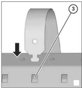
text_image
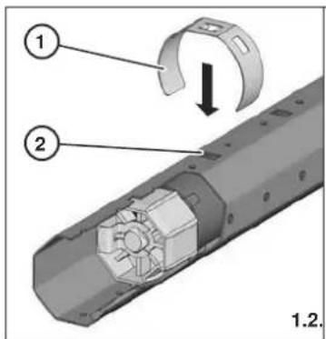
Technical diagram showing a mechanical component with labeled parts and directional arrowIf SW40 winding shafts with exterior fold are used, attaching clips are additionally required.
➢ 1. Approx. every 40 cm, slide an attaching clip (1) over the winding shaft (2) from above.
➢ 2. Insert the securing springs (4) into the rectangular holes in the attaching clips (3).
text_image
Technical diagram showing a mechanical assembly with labeled parts and a directional arrow indicating rotation or movement.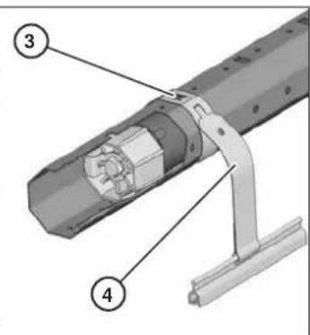
text_image
Technical diagram of a mechanical assembly with numbered components labeled 3 and 4Setting the terminal points
Setting the terminal points defines the upper and lower terminal positions for raising and lowering the roller shutter. These settings can be subsequently changed at any time.
The tubular motor is designed for short-term operation (four minutes). In order to avoid damage due to heating, the motor shuts off automatically on exceeding this period of time or in the event of frequent switching. Allow the motor to cool for approx. 20 minutes in this case.
ATTENTION
Malfunctions due to missing or incorrect terminal point settings.
➢ Make sure that the device is only used with correctly set terminal points.
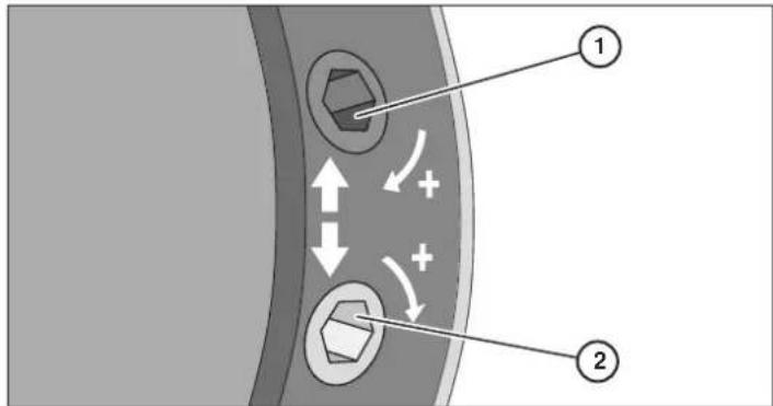
The adjuster screws are located on the tubular motor's driving head.
➢ Use the upper screw (1) to set the lower terminal point.
➢ Use the lower screw (2) to set the upper terminal point.
text_image
Diagram illustrating fluid flow around a valve with labeled components and directional arrowsIn order to extend the travel, turn the screw in the PLUS direction.
In order to shorten the travel, turn the screw in the opposite direction (MINUS).
The direction of rotation of the adjuster screws may vary depending on the model. Pay attention to the labelling on the driving head.
ATTENTION
Damage to the device due to roller shutter curtain shortening as a result of temperature fluctuations.
➢ Set the terminal points so that the roller shutter curtain stoppers have approx. 2-3 cm clearance from the limit stops.
Proceed as follows to set the upper terminal point:
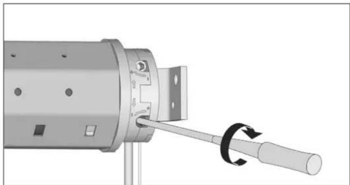
➢ Operate the motor to raise the roller shutter.
If the motor stops before the desired terminal point is reached, proceed as follows:
Leave the remote control set to the raise position.
➢ Use the adjustment tool to carefully turn the lower adjuster screw in the PLUS direction until the motor has reached the desired terminal point.
natural_image
Mechanical assembly diagram showing a cylindrical component with a rotating shaft and mounting holes (no text or symbols)If the motor passes by the desired terminal point, proceed as follows:
Stop the motor.
➢ Operate the motor to lower the roller shutter.
➢ Stop beneath the desired terminal point.
➢ Use the adjustment tool to carefully turn the lower adjuster screw in the MINUS direction.
➢ Operate the motor to raise the roller shutter in order to check the terminal point which has now been set.
If necessary, repeat the steps described above until the desired terminal point is reached.
Proceed as follows to set the lower terminal point:
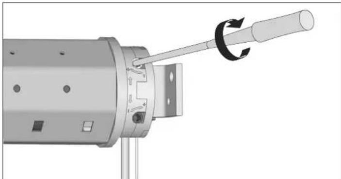
➢ Operate the motor to lower the roller shutter.
If the motor stops before the desired terminal point is reached, proceed as follows:
Leave the remote control set to the lower position.
➢ Use the adjustment tool to carefully turn the upper adjuster screw in the PLUS direction until the motor has reached the desired terminal point.
natural_image
Mechanical assembly diagram showing a cylindrical component with a rotating shaft and mounting holes (no text or symbols)If the motor passes by the desired terminal point, proceed as follows:
Stop the motor.
➢ Operate the motor to raise the roller shutter.
➢ Stop the motor above the desired terminal point.
➢ Use the adjustment tool to carefully turn the upper adjuster screw in the MINUS direction.
➢ Operate the motor to lower the roller shutter in order to check the terminal point which has now been set.
If necessary, repeat the steps described above until the desired terminal point is reached.
Proceed as follows to change the terminal point settings:
➢ Move the roller shutter approximately to the centre position.
➢ Set the terminal points as described above.
Rectifying malfunctions
Rectifying total failure

DANGER
Fatal electric shock due to coming into contact with live components.
Do not carry out any repairs on the device.
▶ Never open the device.
If the device is defective, contact the superrollo customer service.
The cause of a total failure may possibly be a defective motor. A defective motor may be attributable to the following causes:
■ The motor has been severely overloaded due to a fault in the mechanical system.
■ The roller shutter has been blocked due to icing, resulting in motor overload.
If the tubular motor is defective, the device must be dismantled and repaired by the superrollo customer service. Proceed as follows to do this:
Dismantle the device in accordance with the instructions in the chapter entitled Dismantling the device from page 27.
Have the device checked by the superrollo customer service.
Malfunction characteristics and remedies
| Characteristic Possible cause Remedy | ||
| The motor does not run (total failure). | There is no mains voltage. | Make sure that the supply voltage (230 V) is available.Make sure that the device is connected correctly.Information on this can be found in the section entitled Connecting the device from page 22.Have work on the voltage supply carried out by a qualified, trained specialist electrician only. |
| The remote control does not function. | Make sure that a functional 27A-12V battery is inserted. | |
| Device malfunctions. Make sure that the device is | disconnected from the mains power supply.Remove the device.Information on this can be found in the chapter entitled Dismantling the device from page 27. | |
| Motor overload due to sluggish roller shutter as a result of displaced slats. | Make sure that the device is disconnected from the mains power supply.Make sure that the slats are horizontal.Establish the current supply.Move the roller shutter up and down.Lubricate sluggish areas with wax. | |
| Motor overload due to sluggish roller shutter as a result of icing. | Clear away the icing. | |
| The motor does not run (total failure). The maximum operating time (four minutes) has been exceeded. | Allow the device to cool for approx. 20 minutes.Make sure that the device is operated correctly.Make sure that the terminal points are set correctly.Make sure that the roller shutter runs smoothly. | |
| The device does not stop. | The adapter has slipped from the limit ring. | Make sure that the device is disconnected from the mains power supply.Remove the device.Information on removing the device can be found in the chapter entitled Dismantling the device from page 27.Make sure that the adapter is seated flush on the driving head with the groove over the spring.Install the device in reverse order again. |
| The roller capsule is not connected to the winding shaft correctly. | Move the roller shutter down completely.Make sure that the device is disconnected from the mains power supply.Remove the roller shutter from the winding shaft.Make sure that the roller capsule is screwed firmly to the winding shaft. | |
| The winding shaft is too short. Make sure that the | device is disconnected from the mains power supply.Remove the device.Information on removing the device can be found in the chapter entitled Dismantling the device from page 27.Install a new winding shaft.Information on sawing the winding shaft to length and installing it can be found as of the section entitled Sawing the winding shaft to length from page 20.Install the device in reverse order again. | |
| The roller shutter does not move up completely following installation. | The upper terminal point setting is incorrect. Set the | upper terminal pointInformation on this can be found in the section entitled Setting the terminal points from page23. |
| The roller shutter blocks on raising or lowering. | The roller shutter slats have become displaced. | Make sure that all slats are horizontal.Lubricate sluggish areas with wax.In order to pull the roller shutter free, briefly switch the drive on in the opposite direction. |
| The roller shutter scrapes in the roller shutter box due to a lack of pressure rollers on the window frame. | Open the roller shutter box.Install the pressure rollers. | |
| The roller shutter has been rolled up at a slant as the device has not been installed horizontally. | Make sure that the device is disconnected from the mains power supply.Remove the device.Information on removing the device can be found in the chapter entitled Dismantling the device from page 27.Install the device horizontally again.Information on this can be found as of the section entitled Installing the bearings from page 19. | |
| Insulating material has come loose in the roller shutter box and is blocking the roller shutter. | Open the roller shutter box.Remove the insulating material.Contact the manufacturer as regards professional insulation of the roller shutter box. | |
| The roller shutter is too light. Make sure that all slats are horizontal. | Weight the roller shutter e.g. with an appropriate piece of flat iron.Push the piece of flat iron into the bottom slat.In order to pull the roller shutter free, briefly switch the drive on in the opposite direction. | |
Dismantling the device
Proceed as follows to remove the tubular motor:
➢ Operate the motor to lower the roller shutter, until the roller shutter is no longer hanging by the springs and these can be easily released from the winding shaft.

DANGER
Fatal electric shock due to coming into contact with live components.
➢ Do not carry out any connection work on the device when it is connected to the current supply.
➢ Make sure that the device is disconnected from the mains power supply.
➢ Disconnect the cable from the current supply.
➢ Release the securing springs from the winding shaft.
➢ Pull the cotter pin out from the securing hole in the drive bearing's axle pin.
➢ Loosen the screws with which the roller capsule and the winding shaft are screwed together.
▶ Slide the roller capsule up to the limit stop in the winding shaft.
➢ Pull the device out of the bearings.
➢ Pull the tubular motor out of the winding shaft.
Disposing of the device
The environmentally friendly disposal of operating material, electronic assemblies, recyclable materials and other parts of the device is regulated by national and regional laws.
Contact the responsible local authority to obtain precise information on disposal.
➢ Dispose of the device according to the legal regulations via a specialist disposal company.
➢ Dispose of electronic components according to the legal regulations in accordance with the German Electrical and Electronic Equipment Act (ElektroG).


Technical data
| superrollo RM10MSF | superrollo RM10MMF | superrollo RM20MMF | superrollo RM30MMF | |
| Torque (Nm) 10 10 20 30 | ||||
| Rotational speed (rpm) 17 15 | 15 15 | |||
| Voltage (V) / frequency (Hz) 230/50 230/50 230/50 230/50 | ||||
| Output (W) 121 112 145 191 | ||||
| Current consumption (A) 0.53 | 0.49 0.64 0.83 | |||
| System of protection IP 44 44 | 44 44 | |||
| Maximum operating time (min.) | 4 4 4 4 | |||
| Cable length (m) | 2.0 | 2.0 | 2.0 | 2.0 |
| Total length (mm) | 610 630 630 660 | |||
| Shaft type | SW40 | SW60 | SW60 | SW60 |
| Accessories, included | Adapter, driver, drive bearing, securing clip, adjustment tool, 1-channel radio remote control | Adapter, driver, drive bearing, securing clip, adjustment tool, 1-channel radio remote control | Adapter, driver, drive bearing, securing clip, adjustment tool, 1-channel radio remote control | Adapter, driver, drive bearing, securing clip, adjustment tool, 1-channel radio remote control |
| Limit switch range (U) | 30 22 22 22 |
Accessories
| For tubular motor | Article | Article No. |
| RM10MSF | Roller shutter drive accessory set for SW40, consisting of:■ 1 ball bearing■ 1 counter bearing■ 1 roller capsule■ 3 securing springs | SR50450 |
| RM10MMFRM20MMFRM30MMF | Roller shutter drive accessory set for SW60, consisting of:■ 1 ball bearing■ 1 counter bearing■ 1 roller capsule■ 4 securing springs | SR50560 |
Warranty conditions
superrollo Hausautomatisierung GmbH provides a 24-month warranty for new devices which have been installed according to these instructions. The warranty covers all design faults, material faults and manufacturing faults.
The following are excluded from the warranty:
■ Incorrect installation
■ Non-observance of these instructions
■ Improper operation or strain
■ External effects such as shocks, impacts or weathering
■ Repairs and modifications by third-party, unauthorised bodies
■ Use of unsuitable accessories
■ Damage caused by impermissible overvoltage (e.g. lightning)
■ Malfunctions due to radio frequency overlay and other radio interference.
Defects which occur within the warranty period are rectified by superrollo free of charge either by repairing or replacing the affected parts or by supplying an equivalent or new replacement device. The delivery of a replacement or the execution of repair due to warranty reasons does not equate to a general extension of the original warranty period.
EU declaration of conformity
CE symbol and conformity
The superrollo RM10MSF/RM10MMF/RM20MMF/RM30MMF tubular motors meet the requirements of Low-voltage Directive 2006/95/EEC, EMC Directive 2004/108 EEC and all applicable European and national guidelines. Conformity has been verified. The corresponding declarations and documents are stored by the manufacturer.
Motor tubular RM10MSF/RM10MMF/RM20MMF/RM30MMF
text_image
Technical diagram of a mechanical device with numbered components and labeled parts① Contrasoporte* ⑧ Cabeza motriz
text_image
Exploded view diagram of a mechanical assembly with labeled components and partstext_image
D P Y X 1 2 3ATENCIÓN
text_image
Technical diagram of a mechanical assembly with numbered components and an arrow indicating directiontext_image
Technical diagram showing three labeled mechanical components (1, 2, 3) with directional arrows indicating movement or assembly.ATENCIÓN
text_image
Technical diagram showing a mechanical component with numbered parts and an arrow indicating direction, labeled 1 and 2.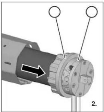
natural_image
Close-up of a mechanical component with arrows indicating direction, no visible text or symbolsnatural_image
Mechanical assembly diagram showing a rotating component with two circular features and an arrow indicating motion (no text or symbols)text_image
Technical diagram showing a mechanical assembly with numbered components and an arrow indicating directiontext_image
Technical diagram of a mechanical assembly with labeled parts 1 and 2, showing a bolted joint and mounting bracket.natural_image
Mechanical component diagram showing a lever and pin assembly (no text or symbols)natural_image
Mechanical assembly diagram showing a pipe connection with a spring and drop drop (no text or symbols)text_image
Diagram of a mobile phone rear panel with four labeled components pointing to the screen interface.① Botón ABRIR (AUF)
③ Botón CERRAR (AB)
② Botón STOP
④ LED de control
text_image
Technical diagram showing a mechanical assembly with labeled parts 1 and 2, and directional arrow indicating motion or force.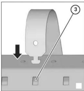
text_image
Technical diagram showing a mechanical component with labeled parts and directional arrowtext_image
Technical diagram showing a mechanical assembly with labeled parts and a directional arrow indicating rotation or movement.
text_image
Technical diagram of a mechanical assembly with numbered components labeled 3 and 4text_image
Diagram showing mechanical or electrical component with labeled parts and directional arrows indicating movement or forcenatural_image
Mechanical assembly diagram showing a cylindrical component with a rotating shaft and mounting bracket (no text or symbols)natural_image
Mechanical assembly diagram showing a shaft being inserted into a cylindrical component with a rotating arrow indicating rotation (no text or symbols present)Motor tubular RM10MSF/RM10MMF/RM20MMF/RM30MMF
Índice
Vista geral 42
Nota prévia....43
text_image
Technical diagram of a mechanical device with numbered components and labeled partstext_image
Exploded view diagram of a mechanical device with labeled parts including control panel, gear, and 34567 component① Motor tubular
② Ferramenta de ajuste
③ Arrastador ⑦ Adaptador
④ Grampo de segurança
text_image
D P Y X ① ② ③ATENÇÃO
text_image
Technical diagram showing three labeled mechanical components (1, 2, 3) with directional arrows indicating movement or assembly.ATENÇÃO
natural_image
Close-up of a mechanical component with arrows indicating direction, no visible text or symbolsnatural_image
Mechanical assembly diagram showing a rotating component with two circular components and an arrow indicating motion (no text or symbols)text_image
Technical diagram of a mechanical assembly with numbered components and an arrow indicating directiontext_image
Technical diagram of a mechanical assembly with numbered components and a downward arrow indicating a specific feature.natural_image
Mechanical component diagram showing a lever and pin assembly (no text or symbols)natural_image
Mechanical assembly diagram showing a pipe connection with a spring and drop drop (no text or symbols)text_image
Diagram of a mobile phone rear panel with four labeled components pointing to the screen interface.① Tecla SUBIR
③ Tecla DESCER
② Tecla PARAR
④ LED de controlo
text_image
Technical diagram showing a mechanical assembly with labeled parts 1 and 2, and directional arrow indicating motion or force.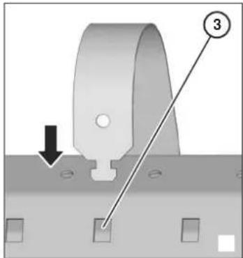
text_image
Technical diagram showing a mechanical component with labeled parts and directional arrow, likely illustrating a machining or assembly process.Se utilizar eixos de rolamento SW40 com encaixe exterior, necessita de grampos de fixação adicionais.
text_image
Technical diagram of a mechanical component with numbered parts and a downward arrow indicating rotation or assembly.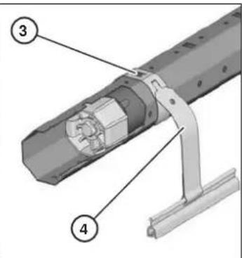
text_image
Technical diagram of a mechanical assembly with numbered components labeled 3 and 4text_image
Diagram illustrating fluid flow around a valve with labeled components and directional arrowsnatural_image
Mechanical assembly diagram showing a cylindrical component with a rotating shaft and mounting holes (no text or symbols)natural_image
Mechanical assembly diagram showing a cylindrical component with a rotating shaft and mounting holes (no text or symbols)text_image
Technical diagram of a mechanical device with numbered components and labeled partstext_image
Exploded view diagram of a mechanical assembly with labeled parts including a cylindrical component, motor, and terminal block 34567.text_image
D P Y X 1 2 3UWAGA
text_image
Technical diagram showing three mechanical components with numbered labels and directional arrows indicating assembly or operation.UWAGA
natural_image
Close-up of a mechanical component with arrows indicating direction, no visible text or symbolsnatural_image
Mechanical assembly diagram showing a motor with a rotating wheel and shaft, labeled with number 2 (no text or symbols on the diagram itself)text_image
Technical diagram showing a mechanical assembly with numbered components and an arrow indicating direction of movement or assembly.text_image
Technical diagram of a mechanical assembly with labeled parts and directional arrow indicating motion or forcenatural_image
Close-up of a mechanical component with a knob and a small pin, labeled with number 3 (no text or symbols on the object itself)natural_image
Mechanical diagram showing a pipe joint with a spring and drop drop, no text or symbols presenttext_image
Diagram of a mobile phone rear panel with four labeled ports and connecting lines① Przycisk GÓRA
② Przycisk STOP
text_image
Technical diagram showing three labeled mechanical components with directional arrows, likely illustrating a assembly or mounting process.text_image
Technical diagram showing mechanical assembly steps with numbered components and directional arrowstext_image
Diagram showing mechanical or electrical component with labeled parts and directional arrows indicating movement or forcenatural_image
Mechanical assembly diagram showing a cylindrical component with a rotating shaft and mounting holes (no text or symbols)natural_image
Mechanical assembly diagram showing a cylindrical component with a rotating shaft and adjustment knob (no text or symbols)Please forward devices for repair to: