
TA70 - Garage door opener Superrollo - Free user manual and instructions
Find the device manual for free TA70 Superrollo in PDF.


| Product Type | Garage Door Opener |
| Drive Type | Chain |
| Power Supply | 220-240 V / 50-60 Hz |
| Motor Voltage | 24 V DC |
| Output Power | 100 W |
| Standby Power | 6 W |
| Tractive Force | 650 N |
| Lighting | 25 W, E14 socket, automatic off after 3 min |
| Door Operating Speed | 11 cm/s |
| Transmission Frequency | 433 MHz |
| Range (Open Terrain) | 50 m |
| Rail Total Length | 3020 mm |
| Max Travel Height | 2560 mm |
| Max Door Area | 10.5 m² |
| Max Infill Weight (Up-and-Over) | 7 kg/m² |
| Noise Level (LpA) | <70 dB(A) |
| Protection | Dry rooms only |
| Permitted Door Types | Swing out standard up-and-over doors, sectional doors |
| Obstruction Recognition | Automatic reversal on contact (power monitoring) |
| Alarm Function | Sounds if door open >10 min, configurable on/off |
| Automatic Closing | Configurable 30 to 240 seconds |
| Emergency Release | Manual cable release for power failure |
| Hand Transmitters Included | 2 x TA70-MHS-RF10 (rolling code) |
| Warranty | 36 months |
Frequently Asked Questions - TA70 Superrollo
User questions about TA70 Superrollo
0 question about this device. Answer the ones you know or ask your own.
Ask a new question about this device
Download the instructions for your Garage door opener in PDF format for free! Find your manual TA70 - Superrollo and take your electronic device back in hand. On this page are published all the documents necessary for the use of your device. TA70 by Superrollo.
USER MANUAL TA70 Superrollo
11.
2.

12.

3.
13.
4.

14.

5.
15.
6.

16.

7.
17.
8.

18.

9.

19.

10.
Schwingtore

Deckensektionaltore


Richtig Falsch
HINWEIS
2.
Legende
RICHTIG

...with your purchase of this garage door operator, you have decided for a quality product. We would like to thank you for your confidence.
The new garage door operator TA70 has been designed in an effort to the graetest possible ease of operation. With uncompromising quality requirements, after extensive test series, we are proud to present this innovative product to you.
CE Mark and Conformity
This present product complies with the requirements of the applicable european and national directives.
The conformity has been proved and the corresponding declarations and documentation are available on file at the manufacturer's premises.
These instructions...

...describe how to install, connect and operate the TA70.
Before you begin work, please read these instructions all the way through and follow all of the safety instructions.
Please save these instructions and give them to any future owners.
For damage resulting from noncompliance with these instructions and safety instructions, the guarantee is void. We assume no liability for any consequent damage.
Key to Symbols

Danger of fatal electric shock
This sign warns of danger when working on electrical connections, components etc. It requires that safety precautions be taken to protect the health and life of the person concerned.

This concerns your safety
Please pay particular attention to and carefully follow all instructions with this symbol.

This symbol advises of malpractices that can cause damage to people and property.
NOTE/IMPORTANT/CAUTION
This is to draw your attention to information which works is important to ensure trouble-free operation.
Correct use
Use the garage door operator only:
◆ to open and close garage doors
◆ for private use
◆ according to the instructions and safety regulations in this manual
Any other use shall be regarded as non-compliant with the intended use.
Correct use of the hand transmitter
The remote control via hand transmitter is only admissible for appliances and equipment in which radio interference in the transmitter or receiver does not present a hazard for persons, animals or property or for which the risk is covered by other safety equipment.
Comply with all maintenance intervals
Proper use also includes the regular inspection of the door and its safety equipment.
Dear Customers....34
These instructions.... 34
Correct use 34
Key to Symbols 34
General View 36
Supply package....37
Operating conditions....38
Improper use....38
Admissible garage door types 38
Inadmissible types of garage door 38
General safety instructions.... 39
Functional description 40
Functional description / Recognition of obstructions...40
Functional description/emergency release 41
Important installation instructions....41
Required tools 42
Remove the door locks 42
Take measurements 43
Assembly of the rails 44
Tension the drive chain 44
Connect the door operator housing to the rail 45
Attachment of the door operator and the rail....46
(A) Installation of the header bracket (1)......47
(B) Installation of the fixing bracket (5) at the door operator head (7)....47
(C) Installation of the door bracket (8)....48
(D) Installation of the middle support clip (13) ..... 49
Important notes after installation....50
Attach safety notices with warning messages .....50
Establish operational readiness of the door 50
Programming 50
Setting limits / setting the upper limit 51
Setting the lower limit 51
Carry out reference run for power measurement ..... 52
Adjust power limiting as required....53
Alarm setting.... 54
Automatic closing time setting 54
2000 cycle alarm setting....55
Conclude programming 56
Method 1: Carry out this method without fail after the reference run....56
Method 2: After all other settings....56
Registering and de-registering hand transmitters ..... 57
Connecting additional electrical equipment....58
Manual door operation 59
Instructions for the user 60
Normal operation....60
Maintenance....61
Monthly checks on the obstacle recognition (power limiting) 61
Technical Specification 62
Trouble shooting 63
CE Mark and EC Comformity 63
Warantee conditions....64


Key
1 = Operator, including lighting
2 = Hand transmitter
3 = LED
4 = 1st hand transmitter button
5 = 2nd hand transmitter button
6 = Set button (S)
7 = Display
8 = Button for adjustment (+)
9 = Button for adjustment (-)
10 = Programming button (P)
1.

11.
2.
12.

3.

13.
4.

14.

5.

15.
6.
16.
7.
17.

8.

18.

9.

19.

10.

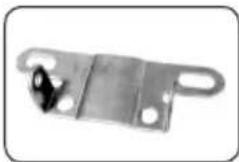
Please compare the contents of the package with the content description on the packaging:
1.
1 x Drive
2.
1 x Operating instructions
3.
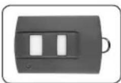
2 x Hand transmitter TA70-MHS-RF10
4.
1 x Door connector, bent
5.
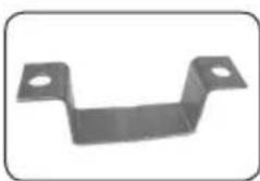
2 x Middle support clip
6.
3 x Fixing bracket
7.
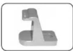
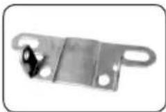
1 x Header bracket
8.
1 x Door bracket
9.
1 x Connector
10.
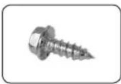
8 x Self-tapping hexagon screw (6 x 15 mm)
11.
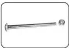
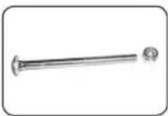
1 x Screw (6 x 80 mm) with hexagon nut
12.
1 x Bolt (8 x 20 mm)
13.
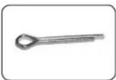
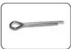
1 x Securing bolt (2 x 20 mm)
14.
4 x Screw (8 x 20 mm) with hexagon nut and plain washer
15.
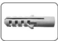
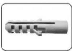
6 x Wall plug (10 mm)
16.
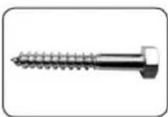
6 x Hexagon head screw (8 x 60 mm)
17.
1 x Spike
18.
2 x Mounting strap
19.
3 x Rails + 2 x Connectors

Operating conditions
EN
◆ Only operate the garage door operator in dry rooms.
◆ The garage door must be able to be opened and closed easily by hand and must not jam.
◆ Ensure that the overhead ceiling tracks are always free of grease and dirt. Dirty overhead ceiling tracks hinder proper operation.
◆ A 220 - 240 V/50 - 60 Hz power supply must be available at the place of installation.

Improper use

Incorrectly performed structural alterations result in the risk of injury.
Do not carry out any structural alterations to the door operator, the garage door or any existing safety equipment which deviate from the measures described in this manual. Such alterations endanger the operating safety.
The garage door operator must not be used:
◆ in commercial establishments
◆ to operate other objects
◆ in continuous operation

Incorrect installation results in the risk of injury.
Movable parts of the garage door must not extend into public footpaths or cycle paths.
The manufacturer is not liable for damage which occurs due to incorrect or non-compliant use (see warranty conditions).

Admissible garage door types
◆ swing out standard up-and-over doors
◆ sectional doors
The doors must move smoothly and comply with the regulations of the following standards: EN 12453 and EN 12604.

Up-and-over doors

Ceiling sectional doors

Inadmissible types of garage door

Doors which require tilting and rotating movements may not be operated with the type TA70 garage door operator.
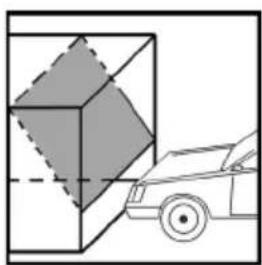
Non swinging out retractable up-and-over door

Important safety instructions CAUTION
For your safety and the safety of others, it is essential that you follow these instructions carefully.
Keep these instructions on file.

All work performed on electrical equipment is associated with a risk of electric shock and electrocution.
◆ Have all work on electrical equipment and on the door operator carried out by a qualified electrician.
◆ Before commencing any work on the door or the door operator, unplug the mains cable from the electrical socket.

The use of defective devices can put people and property at risk.
◆ Never use faulty or damaged devices.
◆ Please make sure that the door operator and mains cable are free from damage.
◆ If the supply cord is damaged, it must be replaced by the manufacturer, its service agent or similarly qualified persons in order to avoid a hazard.
◆ Please notify our customer service department (see page 64) of any faults or damage to the device.

Faulty doors can result in injuries.
◆ The operation of the door must not be hindered by badly adjusted springs or poorly functioning door installation or door constructions.
◆ There is a risk of injury due to the tightly stretched door springs. Never replace the door springs yourself.
◆ Have all work on the door mechanics and the springs carried out by a qualified person.

Power-driven doors entail the risk of crushing and shearing at the closing edge.
◆ Ensure that during operation there are no persons in the swivelling range of the garage door.

Improper use increases the risk of injury.
◆ Never reach into the moving door or into moving parts.
◆ The door should never be operated out of sight without additional safety equipment (e.g. light barrier), see page 58.
◆ Instruct all persons who operate the garage door in the safe use of the equipment.
This device may be used by children from 8 years of page upwards as well as by persons with reduced physical, sensory or mental capacities or with lack of experience and knowledge if they are supervised or have been instructed on how to use the device safely and if they understand what dangers may resulted from this.
◆ Do not allow children to play with the device or with the hand transmitter.
◆ Please store the hand transmitter in such a way that it cannot unintentionally be operated by, e. g. playing children.
◆ Cleaning and user maintenance may not be carried out by children without supervision.
◆ Do not allow anyone to go through under the moving door.
◆ Keep children away when the door is moving.
◆ Drive in and out of the garage only when the door is fully open and stationary.

In the case of defective or inoperable safety equipment there is a danger of injury or damage to property.
◆ Before first operation and thereafter one a month inspect the correct functioning of the safety equipment (e.g. the power limiter).
◆ Never switch off the safety equipment.
◆ Keep the door limit stop on the ground free of ice, snow, dirt and stones.
Intelligent microcomputer
Intelligent, computerized, exact positioning of travel, prompt power determination, reverses if obstructions are met.
Door operator
Low noise, soft start and soft stop protect the motor and ensure a long service life.
Self diagnosis
Operational mode and digital menu shown on the display, self diagnosis. (L-Normal, F-Interrupted, H-Fail In Reading, A-Infrared Ray Interrupted)
Cryptoguard
Rolling code technology provides billions of code combinations and makes every remote control a unique one that protects against unauthorized access.
Alarm unit
The alarm sounds when the door is left open for longer than 10 minutes. The alarm stops when the door is closed again (refer to „Alarm setting“ on page 54).
Emergency release device
The door can be manually operated by pulling down on the emergency release cable in the case of power failure.
Automatic closing function
The automatic closing time of the door can be set from 30 to 240 seconds (refer to page 54/55).
2000 cycle alarm
When the operator has run 2000 cycles, it will beep to remind the user to service the mechanical system (refer to page 55).
Lighting
The TA70 garage door operator has internal lighting which is switched on after each switching impulse and goes off again automatically after 3 minutes.
Additional connecting options for external accessories and safety unit
In addition you can connect an external switch and an infrared photoelectric barrier (refer to page 58).
Functional description / Recognition of obstructions
The door operator has an automatic obstacle-recognition system (through internal monitoring of power).
If the door encounters an obstruction when closing or opening, the door operator stops the door automatically and moves it in the opposite direction until it reaches the corresponding limit.
After removing the obstruction you can operate the garage door operator normally again.
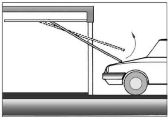
In the event of a power cut, the door can be operated manually by pulling the emergency release cable.

There is a risk of injury. The door can fall un-controllably when it is released (e.g. if springs are weak or broken, or if the door is not properly balanced).
◆ Always close or open the door fully after each release.
◆ The emergency release is not intended for „everyday use“.


Important installation instructions

CAUTION
Important instructions for a safe installation. Follow all installation instructions carefully.
An incorrect installation can lead to serious injuries.

Before installation check...:
◆ ...whether your door operator is suitable for the type of garage door and the garage door height.
◆ ...that the door is in a perfect mechanical state. The door must be smooth running and be balanced. Check whether it opens and closes properly;
Open the door approx. 1 metre and let go. A balanced door should now remain in this position. If not, have your door adjusted by a specialist company.
◆ The door operation must not be hindered by incorrectly adjusted springs or by incorrectly functioning door suspensions or door constructions.
Before installing the drive...,
....remove all unnecessary ropes or chains and disable any equipment, such as locks, not needed for powered operation.

Faulty installation can result in serious accidents and injuries.
◆ Fit the actuator for the emergency release at a height of less than 1.8 metres.
◆ Use only the enclosed mounting materials and only original spare parts and original accessories.
◆ Any existing door locking devices already fitted to the door may hinder the correct functioning of the door and must therefore be removed.
◆ Poor lighting hinders the installation work and can result in injuries. Ensure that there is adequate lighting during installation work.
It is possible that during the installation work, you may not be able to open the door for a short period of time.
◆ Drive is not to be used with doors having openings exceeding 10 mm in diameter or having edges or protruding parts a person could grip or stand on.
◆ Permanently fix the labels warning against entrapment in a prominent place or near any fixed controls.
◆ Permanently fix the label concerning the manual release adjacent to its actuating member.

During installation there is a danger of injury due to the unsecured door falling suddenly.
◆ During the installation work, ensure that there are no persons in the swivelling area of the garage door.
You require the following tools.


Remove the door locks
- Remove all vertical and horizontal door locks and catches.
IMPORTANT!
Keep the „old“ door locks in a safe place.
In the event that you should remove the garage door operator, you will have to fit these again in order to restore the original state of the door.

1. Measure up and mark the centre of the door.
Mark the centre of the door, as shown, on the upper edge of the door, on the door lintel and on the garage ceiling.


2. Determine the distance between the top edge of the door and the ceiling.
Close the door slowly and measure the distance between the top edge of the door and the ceiling.
NOTE
The minimum distance should be 6 cm.

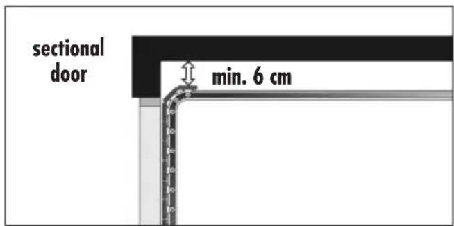
3. Installation advice for fitting to sectional doors.
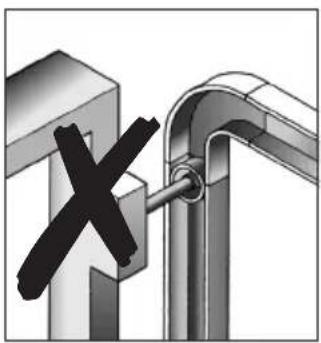
If the garage door operator is used for a sectional door, then the guide roller of the upper door segment must be in the bend of the guide rail when the door is closed.
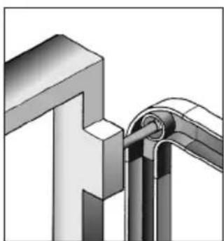

Right Wrong
NOTE
The TA70 is supplied with three rails:
◆ two end pieces, including a pre-assembled chain.
◆ a middle piece (without a chain) with two connectors.
- Lay the two end pieces with the pre-assembled chain on the ground, with the chain lying as straight as possible between the two end pieces.
- Push the two enclosed connectors onto the middle piece and then lay the middle piece in the gap between the two end pieces.
- Insert the chain into the middle piece.
- Push each of the connectors onto the join between the middle piece and each of the end pieces.
Please ensure that each of the connectors lies in the centre between the fixing plates of the rail underside.
- Finally, bend the fixing plates outwards with a small screwdriver.
As a result, the connectors can no longer be moved.


Tension the drive chain
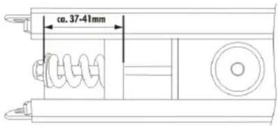
- Screw the clamping nut tight with a suitable socket key ( 10 mm).
- Adjust the tension of the chain as shown in the picture.
ATTENTION:
Due to manufacturing tolerances, the shown range of approx. 37-41 mm can vary.
Make shure that the chain sags a little on the full length of the rail, so that it is not stretched too tight. Otherwise it can result in a loss of power the drive.
1.

2.

- First of all insert the connector (5).
- Place the rail (4) with the inboard chain sprocket (supplied pre-assembled in the rail) over the connector (5).
- Place the two fixing brackets (2) over the rail (4) and screw these firmly onto the door operator housing with the enclosed self-tapping hexagon screws (6 x 15 mm).
IMPORTANT
Ensure that the microswitch (3) is not damaged when mounting the rail.

Key
1 = Self-tapping hexagon screw (6 x 15 mm)
2 = Fixing brackets
3 = Microswitch
4 = Rail
5 = Connector

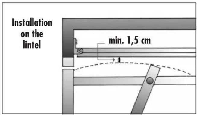
Installation on the lintel
The installation should preferably be on the lintel, as this means that the forces encountered can best be absorbed.
Installation on the ceiling
For installation on the ceiling, you should rotate the header bracket by 90 degrees and fix it to the ceiling further inward. The full rail length can then be used as a result.
NOTE
When fitted to the ceiling, the distance to the door leaf must be a maximum of 25 cm.
IMPORTANT
In the case of garage walls or garage ceilings made of stone (concrete), use the enclosed hexagon screws (8 x 60) and wall plugs ∅ 10 mm.

NOTE
The header bracket (1) must be aligned with the midpoint of the door.

- Mark out the position of the header bracket (1) and drill the mounting holes (e.g. with a 10 mm masonry drill bit).
- Screw the header bracket (1) tight with the enclosed hexagon screws (8 x 60 mm).
- Then fix the rail (4) with the enclosed hexagon screw (6 x 80 mm) to the header bracket (1).
Key
1 = Header bracket
2 = Screw (6 x 80 mm) with hexagon nut
3 = Hexagon screw (8 x 60 mm)
4 = Rail

(B) Installation of the fixing bracket (5) at the door operator head (7)
- Push the fixing bracket (5) onto the rail (4), as close to the door operator head (7) as possible.
- Mark the mounting holes for the fixing bracket (5).
In order to do so, lift the entire construction and push it against the ceiling.
NOTE
Ensure that the rail (4) is aligned with the centre of the door.
-
Drill the mounting holes (e.g. with a 10 mm masonry drill bit).
-
Finally screw the fixing bracket (5) to the garage ceiling with the enclosed hexagon screws (8 x 60 mm).

Key
4 = Rail
5 = Fixing bracket
6 = Hexagon screw (8 x 60 mm)
7 = Door operator head
NOTE
We recommend fixing the door bracket (8) to the door frame if possible.
For plastic or thin-walled wooden doors, additional cross-beams are necessary in order to avoid damaging the door. In this case, consult your door supplier.
Use existing drillholes, if possible, to mount the door bracket (8).
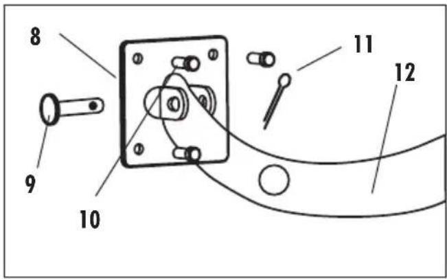
Key
8 = Door bracket
9 = Bolt (8 x 20 mm)
10 = Self-tapping hexagon screw (6 x 15 mm)
11 = Securing bolt (2 x 20 mm)
12 = Door connector, bent
-
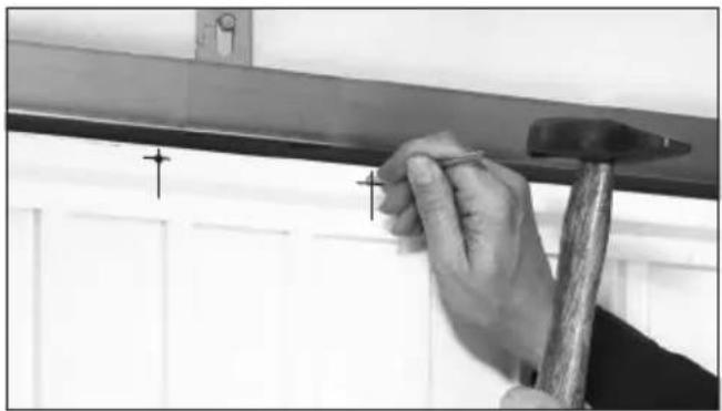
Place the door bracket (8) on the top edge of the garage door and align it with the centre of the door (in a line with the profile slide). Next, mark out the four fixing holes on the door frame.
-
Punch in the fixing holes in the door frame with the aid of the enclosed spike
NOTE
Self-tapping screws need sufficient hold in the material. Check the thickness of your door frame. If it is sufficiently thick you can also pre-drill the fixing holes with a 4 mm metal drill bit if you are not able to punch in the holes with the spike.


- Screw the door bracket (8) tight with the enclosed self-tapping hexagon screws (8 x 15 mm).
- Finally, fix the door connector (12) to the door bracket (8) with the enclosed bolt (9).
NOTE
A straight door connector is supplied pre-assembled, and this is permanently fixed to the rail.
If you wish to use the bent door connector enclosed (depending upon your door particular configuration), you must attach this with two hexagon screws (8 x 20) to the straight door connector (12).
- Finally, secure the bolt (9) by attaching the securing bolt (11) to prevent it from slipping out.


(D) Installation of the middle support clip (13)
- Fit the middle support (13) clip at a suitable place, as near as possible to the middle point between the door and the door operator head.
Key
13 = Middle support clip
14 = Hexagon screws (8 x 60 mm)


◆ After installation, ensure that the mechanism is properly adjusted and that the drive reverses when the door contacts a 50 mm high object placed on the floor (for drives incorporating an entrapment protection system depending on contact with the bottom edge of the door), s. page 61.
◆ After installation, ensure that the drive prevents or stops the opening movement when the door is loaded with a mass of 20 kg, fixed centrally on the bottom edge of the door. This applies especially to drives which can be used with a door that has openings in the door leaf larger than 50 mm in diameter.

Attach safety notices with warning messages
Improper use results in an increased risk of injury.
◆ Permanently fix the labels warning against entrapment in a prominent place or near any fixed controls.
◆ Permanently fix the label concerning the manual release adjacent to its actuating member.
◆ Attach all labels so that they are clearly legible.

Establish operational readiness of the door
- Move the door carefully, in order to engage the profile slide.
- Plug the mains plug into the socket and switch on the electricity.
- The light goes on and the unit gives a single beep and the display shows '0' at regular intervals.

Programming

In order that the following settings are correctly stored and executed, you must carry out a final programming procedure according to page 56.

Carrying out the instructions in the wrong order when setting the limits will result in malfunctions. Be sure to keep to the setting order specified.
Correct setting order:
- Set upper limit
- Set lower limit

- Press "P" for approx. 5 seconds.
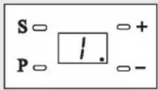
- The door operator beeps and shows "1".
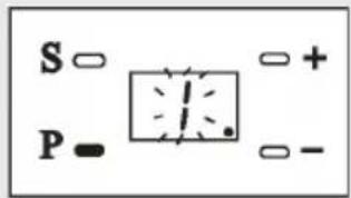
- The door opens or closes.
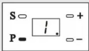
- If the door has moved upwards to the required position, press „P“ to store the upper limit.

Setting the lower limit
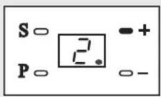
- Press „+“, the display shows „2“.

- The door opens or closes.
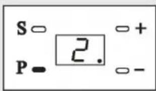
- If the door has moved downwards to the required position, press „P“ to store the lower limit.

During the reference run there is a risk of injury, as the door operator develops extremely strong forces.

- Press „+“, the display shows „3“.

- The door goes up automatically.

- After it has stopped, press the „P“ button twice.

- The door goes down.

- After it has stopped, press "P", to store the information.

- Conclude the programming (refer to page 56, method 1).
IMPORTANT
Once you have set the two limits and the reference run for power measurement, you have fulfilled the basic settings required for safe operation.
If you do not require any further settings, you must conclude programming as specified in method 1 on page 56, in order to adopt the basic settings you have just programmed.
After this, you can conclude the following individual settings, either singly or after all the settings have been programmed, using method 2 on page 56.
NOTE
The door operator is preset to stage 3 by the supplier. If required (e.g. if the power level is too low) you can subsequently adjust the power limiting setting.

If the power level is too low, the door movement will be impaired, particularly if the mechanical structure of the door is not well balanced.

- Press „+“ (if necessary press several times) until „4“ is displayed.

- Press „P“, the display shows „7“ (stage 3).

- Press „+“ or press „-“ to select the stage.


- Press „P“, in order to store the setting.

- IMPORTANT
Repeat reference run for power limiting (refer to page 52).

- Conclude programming (refer to page 56, method 1).

After a resetting of the power level, it is absolutely necessary to repeat the reference run for power limiting and to conclude the programming again.
During the reference run there is a risk of injury as the door operator develops extremely strong forces.

If the alarm is switched on, the door operator beeps if the door is open for longer than 10 minutes. The door operator beeps for 30 seconds every 10 minutes.
To end the beeping:
Press the door control button to fully close the door.
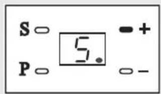
- Press „+“ (press several times if necessary) until „5“ is displayed.
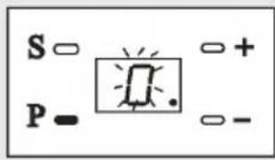
- Press „P“, the display is „0“. (0 = off = factory setting)
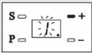
- Press „+“, the display is „1“. (1 = on = the alarm setting is switched on)

- Press "P" in order to store the alarm setting.
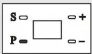
- Conclude programming (refer to page 56, method 2) or proceed with next setting.

Automatic closing time setting
NOTE
Before the door closes automatically, the door operator beeps for 20 seconds. At the same time the light flashes.
When the door starts closing, the light shines durably and it beeps permanently.
After the door has closed, the door operator ends the beeping and the light remains on for a further 3 minutes.
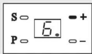
- Press „+“ (press several times if necessary) until „6“ is displayed.
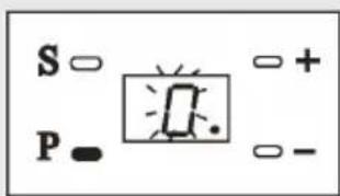
- Press „P“, the display is „0“. (0 = off = factory setting)

- Press „+“, the display is „1”. (1 = on = automatic closing time = 30 seconds)
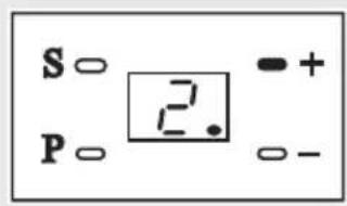
- Press „+“ and select the required closing time:
1 = 3 0 . 5 = 1 5 0 . 2 = 6 0 . 6 = 1 8 0 . 3 = 9 0 sec. 7 = 2 1 0 sec. 4 = 1 2 0 . 8 = 2 4 0 .
(maximum)

- Press „P“ in order to store the setting.
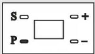
- Conclude programming (refer to page 56, method 2) or proceed with the next setting.

2000 cycle alarm setting

After a period of time in use, regularly check to see whether the door is level when opening/closing, and whether the spring has enough force to raise the door.
Add a suitable amount of lubricant to all moving parts regularly.
NOTE
If this function is activated, after 2000 cycles the door operator will indicate with a short whistling tone at regular intervals that door maintenance must be carried out.
To end the alarm tone
Switch the power supply off and then on again, or press the „P“ button for the door for 5 seconds.

- Press „+“ (press several times if necessary) until „7“ is displayed.

- Press „P“, the display is „0“.
(0 = off = factory setting )
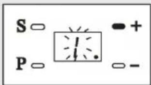
- Press „+“, the display is „1“.
(1 = on )
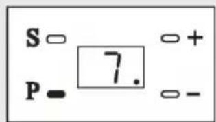
- Press „P“ in order to store the setting.
- Conclude programming (refer to page 56, method 2) or proceed with next setting.
IMPORTANT
Please note: this concluding step must be carried out, otherwise the information stored will be lost.
NOTE
You can conclude the programming in two ways:
Method 1: Carry out this method without fail after the reference run.

- After the reference run, press „-“ (press several times if necessary) until „1“ is displayed.

- Keep „P“ pressed for 5 seconds.
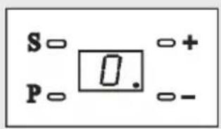
- "0" will be displayed at regular intervals in order to conclude the programming and set the door operator into an idle state.
Method 2: After all other settings

- After completing any setting, press „P“ for 5 seconds.

- "0" will be displayed at regular intervals in order to conclude the programming and set the door operator into an idle state.
Registering hand transmitters:

- Press „S“ for 1 second and then let go.

- As acknowledgement, a green point will appear for a short time at the bottom right of the display.

- Press the previously set button on the hand transmitter three times.
NOTE
After successfully registering you can operate your garage door operator with the hand transmitter. After that you can also register further hand transmitters.
De-registering hand transmitters:

For security reasons, a hand transmitter must be de-registered in the event of loss, to prevent the garage door from being operated by unauthorised persons.

- Press „S“ and keep pressed.

- As acknowledgement, a green point will appear for a short time on the bottom right of the display.

- Keep „S“ pressed until the green point at the bottom right of the display disappears.
All hand transmitters are de-registered. You can register a new hand transmitter.

When working on electrical systems there is a risk of danger to life due to electrocution.
◆ The connection of additional electrical equipment must only be carried out by a qualified electrician.
Before opening the protective cover always disconnect the equipment from the mains power supply and check that the system is free of voltage.

Accessories from other manufacturers may result in malfunctions or damage to property.
◆ Use only original accessories. A separate source voltage at the screwtype terminal for the external switch will result in a short circuit and will destroy the door operator's electronics.
Do not connect any separate source voltages to the terminal for the external switch. The terminals are potential-free contacts.

If the external buttons are not connected properly, the operational safety of the equipment is at risk.
Always mount the internal button, programming button, etc.:
◆ outside the reach of movable parts
◆ within visibility of the door
◆ at a height of at least 1.5 metres
![graph TD A["TA70"] --> B["(1)"] B --> C["EMERGEDDOR"] C --> D["24 VGNDIR1"] D --> E["GND"] D --> F["VCC"] D --> G["COM IR"] C --> H["Warning Symbol"] style A fill:#f9f,stroke:#333 style B fill:#ccf,stroke:#333 style C fill:#cfc,stroke:#333 style D fill:#fcc,stroke:#333 style E fill:#ffc,stroke:#333…](/content/2026/05/782226/images/8d5a54ae532676839a4e16f121f7eda8f82f1f7e73bcddba4b7c223251a4898b.jpg)
Key
(1) = main board
(2) = infrared light barrier (optional)
(3) = external switch (optional)
(4) = pass door contact

NOTE!
Remove the respective factory installed bridge before connecting a light barrier or a pass door contact.

In the case of power failure:
- If you wish to manually operate the door in the event of a power cut, you must pull the emergency release cable so that this releases the door from the door operator.
After that you can move the door freely.

There is a risk of injury. The door can fall down uncontrollably when released (e.g. if the door is not balanced)
◆ Close or open the door fully after each release.
◆ The emergency release is not intended for "everyday use".
If power recovers:
- NOTEOperate the hand transmitter or the wall switch.
Engagement happens automatically.
Notes for use
◆ Check the operator system to determine whether it moves smoothly the first time the garage door operator is used.
◆ After some time in use, check regularly to see whether the door remains horizontal when opening and closing and whether the spring has enough power to lift the door. Lubricate all movable parts regularly with a suitable lubricant.
◆ In the event of a power cut, you can pull the emergency release and freely move the door manually.
When the power is back, you can operate the hand transmitter or the wall panel, and the emergency release will engage automatically.
The door can then be operated again with the hand transmitter or the wall panel.

- In the event of a power cut, the door stops moving.

- Once the power is back on, press a button on the hand transmitter, and the door will open.
- According to the program memory, the door will open as far as the upper limit and then stop.
Normal operation
◆ Remote control
By pressing the previously set button on the hand transmitter, the door can be opened, closed or stopped.
◆ Manual operation
In the event of a power cut, the door can be opened or closed manually as soon as the door operator has been disengaged (refer to page 59).

Defective door systems and safety equipment result in the risk of injury.
For your safety, you should comply with the recommended maintenance intervals for your door system, including all safety equipment.
Maintenance interval:
Have the door system inspected by a specialist company before initial operation and then as required, but at least once a year.
Regular checks of wearing parts:

There is a risk of injury due to defective or worn components.
Check the system therefore regularly for signs of wear, damage or lack of balance of the door.
Do not use the door under any circumstances if repairs or adjustments need to be made, as a faulty or imbalanced door can lead to injuries.
Check:
◆ All screw connections to ensure they are tight
◆ Cables for damage
◆ Springs and fixing parts

There is a risk of injury due to the extremely taut door springs.
◆ Never replace the door springs yourself.
◆ Have all work on the mechanical system and springs carried out by a qualified person.

Monthly checks on the obstacle recognition (power limiting)
- Run the door into the final open position.
- Place a 50 mm high object, e.g. a wooden block, in the direction of travel of the door.
- Close the door by actuating the hand transmitter.
- If the door hits an obstruction when closing, the door operator automatically stops and opens the garage door fully.
- After this, remove the obstruction.
- After removing the obstruction, you can operate the garage door operator nor-mally again.

Placing an approx. 50 mm wooden block in the direction of travel of the door.

If necessary, correct and check the alignment once again, as an incorrect alignment cause pose a threat, see page 53.
Model and recommended use
| Item no. Voltage (V) Door size (m) | 2) Admissible ambient temperature (°C) | ||
| SR40070 | 220 - 240 ≤ 10 | -20...+40 | |
Guide rail and available sizes
| Item no. | Total length | Height of travel | Lifting height |
| SR40070 | 3020 mm | 2560 mm < 2240 mm |
Technical Data
| Output: 100 W | |
| Standby mode: 6 W | |
| Tractive force: 650 N | |
| Supply voltage: 230 V / 50 Hz | |
| Motor: 24 V (DC) direct current | |
| Light: 25 W; E14 | |
| Door operating speed: | 11 cm/second |
| Fuse model:- Light fuse 2: | 2.5 A |
| Transmission frequency and range: | 433 MHz/open terrain 50 m |
| Drive: | chain |
| Method of protection: | Use only in dry rooms |
| Noise pressure level (LpA): | ≤70 dB(A) |
Permitted garage door dimensions
| Permitted door leaf surface: | 10.5 m2 (for easy to move up-and-over doors and sectional doors) |
| Maximum infill weight for up-and-over doors: | 7 kg/m2 |
| Error | Causes | Solution |
| The door operator does not work. | 1. The plug is not inserted properly.2. The fuse has been tripped. | 1. Plug the mains plug into the mains outlet.2. Have the cause checked by a qualified person, then switch the fuse back on again. |
| The hand transmitter cannot actuate the door operator. | 1. The hand transmitter may have been wrongly registered or has not been registered at all.2. The battery is out of power. | 1. Register the hand transmitter again, refer to page 57.2. Replace the battery |
| The operating range of the hand transmitter is too restricted. | The battery may be empty. | Replace with a new one of the same model. |
| The chain moves, but the door does not. | The emergency release may have been triggered. | Operate the door operator until the emergency release engages again automatically. |
| When operating, a grating sound can be heard. | There is not sufficient lubricant between the rail and the chain slide after long use. | Insert a suitable lubricant in the position between the rail and the chain slide. |
| The chain has some sag and is noisy. | The chain is loose due to long use without lubricant between the rail and the chain slide. | Tension the chain as described on page 44 and apply a suitable lubricant to the chain. |
CE Mark and EC Comformity
The garage door opener of series TA70 (Item no. SR40070) inclusive Hand transmitter, complies with the requirements of the current European and national directives.

2006/42/EC Machinery directive
1999/5/EC R&TTE directive
Conformity has been verified. The corresponding declarations and documentation are available on file at the manufacturer's premises. superrollo Hausautomatisierung GmbH
Gewerbepark 1
01156 Dresden
Germany
Superrollo Hausautomatisierung GmbH warrants all new devices for 36 months, that have been installed in accordance with the installation manual. The guarantee covers all design faults, material faults and fabrication faults.
Your statutory warranty claims shall remain unaffected by this warranty.
The guarantee does not cover:
◆ Incorrect mounting or installation
◆ Non-observance of the installation and operation manual
◆ Improper operation or utilisation.
◆ External influences such as knocks, blows or weather
◆ Repairs and modifications made by unauthorised third parties
◆ Use of unsuitable accessory parts
◆ Damage due to inadmissible voltage surges (e. g. caused by lightning)
◆ Dysfunction due to superimposed radio frequencies and other radio disturbances.
For the warranty to be applicable, the new device must have been purchased through one of our approved specialist retailers. Proof of this can be provided by presenting a copy of the bill.
Any defects occurring within the period of guarantee will be rectified by superrollo Hausautomatisierung GmbH at no cost either by repairing or replacing the parts concerned or by delivery of a device of the same value or a new replacement. Generally the original guarantee period will not be extended because of replacement delivery or repair resulting from the guarantee.
Please send equipment for repair to:
01156 Dresden (Germany)
Service-Hotline: 01807 001-655 *
* 30 seconds free of charge, subsequently 14 cents/minute from German fixed line networks and max. 42 cents/minute from German cellular networks.


- HINWEIS
- LEGENDE
- CE MARK AND CONFORMITY
- THESE INSTRUCTIONS
- KEY TO SYMBOLS
- DANGER OF FATAL ELECTRIC SHOCK
- THIS CONCERNS YOUR SAFETY
- THIS SYMBOL ADVISES OF MALPRACTICES THAT CAN CAUSE DAMAGE TO PEOPLE AND PROPERTY
- NOTE/IMPORTANT/CAUTION
- CORRECT USE
- USE THE GARAGE DOOR OPERATOR ONLY
- CORRECT USE OF THE HAND TRANSMITTER
- COMPLY WITH ALL MAINTENANCE INTERVALS
- KEY
- PLEASE COMPARE THE CONTENTS OF THE PACKAGE WITH THE CONTENT DESCRIPTION ON THE PACKAGING
- OPERATING CONDITIONS
- IMPROPER USE
- INCORRECTLY PERFORMED STRUCTURAL ALTERATIONS RESULT IN THE RISK OF INJURY
- THE GARAGE DOOR OPERATOR MUST NOT BE USED
- INCORRECT INSTALLATION RESULTS IN THE RISK OF INJURY
- ADMISSIBLE GARAGE DOOR TYPES
- INADMISSIBLE TYPES OF GARAGE DOOR
- DOORS WHICH REQUIRE TILTING AND ROTATING MOVEMENTS MAY NOT BE OPERATED WITH THE TYPE TA70 GARAGE DOOR OPERATOR
- IMPORTANT SAFETY INSTRUCTIONS CAUTION
- ALL WORK PERFORMED ON ELECTRICAL EQUIPMENT IS ASSOCIATED WITH A RISK OF ELECTRIC SHOCK AND ELECTROCUTION
- THE USE OF DEFECTIVE DEVICES CAN PUT PEOPLE AND PROPERTY AT RISK
- FAULTY DOORS CAN RESULT IN INJURIES
- POWER-DRIVEN DOORS ENTAIL THE RISK OF CRUSHING AND SHEARING AT THE CLOSING EDGE
- IMPROPER USE INCREASES THE RISK OF INJURY
- IN THE CASE OF DEFECTIVE OR INOPERABLE SAFETY EQUIPMENT THERE IS A DANGER OF INJURY OR DAMAGE TO PROPERTY
- INTELLIGENT MICROCOMPUTER
- DOOR OPERATOR
- SELF DIAGNOSIS
- CRYPTOGUARD
- ALARM UNIT
- EMERGENCY RELEASE DEVICE
- AUTOMATIC CLOSING FUNCTION
- 2000 CYCLE ALARM
- LIGHTING
- ADDITIONAL CONNECTING OPTIONS FOR EXTERNAL ACCESSORIES AND SAFETY UNIT
- FUNCTIONAL DESCRIPTION / RECOGNITION OF OBSTRUCTIONS
- IMPORTANT INSTALLATION INSTRUCTIONS
- CAUTION
- BEFORE INSTALLATION CHECK
- BEFORE INSTALLING THE DRIVE
- DURING INSTALLATION THERE IS A DANGER OF INJURY DUE TO THE UNSECURED DOOR FALLING SUDDENLY
- REMOVE THE DOOR LOCKS
- IMPORTANT
- MEASURE UP AND MARK THE CENTRE OF THE DOOR
- DETERMINE THE DISTANCE BETWEEN THE TOP EDGE OF THE DOOR AND THE CEILING
- NOTE
- INSTALLATION ADVICE FOR FITTING TO SECTIONAL DOORS
- TENSION THE DRIVE CHAIN
- ATTENTION
- INSTALLATION ON THE LINTEL
- INSTALLATION ON THE CEILING
- INSTALLATION OF THE FIXING BRACKET (5) AT THE DOOR OPERATOR HEAD (7)
- INSTALLATION OF THE MIDDLE SUPPORT CLIP (13)
- ATTACH SAFETY NOTICES WITH WARNING MESSAGES
- IMPROPER USE RESULTS IN AN INCREASED RISK OF INJURY
- ESTABLISH OPERATIONAL READINESS OF THE DOOR
- PROGRAMMING
- SETTING THE LOWER LIMIT
- AUTOMATIC CLOSING TIME SETTING
- 2000 CYCLE ALARM SETTING
- TO END THE ALARM TONE
- METHOD 1: CARRY OUT THIS METHOD WITHOUT FAIL AFTER THE REFERENCE RUN
- METHOD 2: AFTER ALL OTHER SETTINGS
- REGISTERING HAND TRANSMITTERS
- DE-REGISTERING HAND TRANSMITTERS
- WHEN WORKING ON ELECTRICAL SYSTEMS THERE IS A RISK OF DANGER TO LIFE DUE TO ELECTROCUTION
- ACCESSORIES FROM OTHER MANUFACTURERS MAY RESULT IN MALFUNCTIONS OR DAMAGE TO PROPERTY
- IF THE EXTERNAL BUTTONS ARE NOT CONNECTED PROPERLY, THE OPERATIONAL SAFETY OF THE EQUIPMENT IS AT RISK
- NOTES FOR USE
- NORMAL OPERATION
- CHECK
- MONTHLY CHECKS ON THE OBSTACLE RECOGNITION (POWER LIMITING)
- CE MARK AND EC COMFORMITY
- THE GUARANTEE DOES NOT COVER
Brand : Superrollo
Model : TA70
Category : Garage door opener