NB-B24 - Heating Just Fire - Free user manual and instructions
Find the device manual for free NB-B24 Just Fire in PDF.


User questions about NB-B24 Just Fire
0 question about this device. Answer the ones you know or ask your own.
Ask a new question about this device
Download the instructions for your Heating in PDF format for free! Find your manual NB-B24 - Just Fire and take your electronic device back in hand. On this page are published all the documents necessary for the use of your device. NB-B24 by Just Fire.
USER MANUAL NB-B24 Just Fire
(PLEASE KEEP THESE INSTRUCTIONS FOR FUTURE REFERENCE)
A LIFETIME OF WARMTH
*Please read this entire manual before installation and use of this pellet fuel burning room heater. Failure to follow these instructions could result in property damage, bodily injury, or even death.
*Save these instructions!
INSTALLER: THIS MANUAL MUST STAY WITH APPLIANCE!
INTRODUCTION 3
- WARNING AD WARRANTY 4
1.1.SAFETY INSTRUCTIONS 4
1.2. OPERATING INSTRUCTION ....5
1.3. IMPORTANT INFORMATION FOR CORRECT DISPOSAL OF THE PRODUCT IN ACCORDANCE WITH EC DIRECTIVE 2002/96/EC ....5
1.4. GUARANTEE CONDITIONS ...... 6
1.4.1. Limitations ......6
1.4.2. Exclusions ...... 6
- THEORETICAL NOTIONS FOR INSTALLATION ....7
2.1.Pellets 7
2.2. PRECAUTIONS FOR INSTALLATION 8
2.3. OPERATING ENVIRONMENT 9
2.4. CONNECTION TO THE EXTERNAL AIR INTAKE .... 9
2.5. CONNECTION OF SMOKE DISCHARGE PIPE ..... 10
2.6. CONNECTION TO THE CHIMNEY .....10
2.7. CONNECTION TO AN EXTERNAL FLUE WITH INSULATED OR DOUBLE-WALL PIPE 10
2.8. CONNECTION TO THE FLUE PIPE 11
2.9. OPERATING PROBLEMS CAUSED BY DRAUGHT DEFECTS IN THE FLUE 11
2.10. HYDROLIC CONNECTION ....12
- INSTALLATION AND ASSEMBLY 12
3.1. DRAWINGS AND TECHNICAL CHARACTERISTICS.... 12
3.1.1. Dimensions of HYDRO stoves 12
3.1.2. Technical DATA SHEET.... 13
3.2. PREPARATION AND UNPACKING 14
3.3. Hydro CONNECTION DIAGRAM 14
3.3.1. Connections to the system 15
3.3.2. Filling the water network ....16
3.3.3. Water characteristics 16
3.4. KIT WATER PRODUCTION 17
PELLET BURNING STOVES
INSTALLATION AND MAINTENANCE MANUAL
3.5. EXAMPLE INSTALLATION DIAGRAMS .....17
3.5.1. Installation diagram for heating system with domestic hot water kit (SUITE/CLUB/MUSA) 17
3.5.2. Heating installation in combination with a storage tank ....18
3.5.3. Heating installation diagram in combination with a boiler.... 19
4. OPERATION 20
5. MAINTENANCE AND CLEANING 32
5.1. DAILY OR WEEKLY CLEANING PERFORMED BY THE USER .... 32
5.1.1. BEFORE EACH IGNITION ....32
5.1.2. Check every 2/3 days ....32
5.1.3. Cleaning the glass 32
5.1.4. Cleaning of stainless steel and satin-finish surfaces ....33
5.1.5. Cleaning of painted parts ....33
5.2. CLEANING TO BE PERFORMED BY SPECIALIZED TECHNICIAN ....33
5.2.1. Cleaning the heat exchanger and the pipe unit ....33
5.2.1.1. CLEANING THE EXCHANGER AND PIPE UNIT (EGO/STAR) 33
5.2.1.2. CLEANING THE EXCHANGER AND PIPE UNIT (SUITE/MUSA and CLUB): ....34
5.2.2. Shutting the stove down (end of season) 34
5.3. CHECK OF INTERNAL COMPONENTS ....35
6. PROBLEMS / CAUSES / SOLUTIONS 37
7. ELECTRICAL DIAGRAMS 41
INSTALLATION AND MAINTENANCE MANUAL
INTRODUCTION
Dear Customer,
First, we wish to thank you for the preference granted to GRACE DESIGN products and in particular to a stove from our Hydro line.
In order to obtain the optimum performance of the stove and to enjoy the warmth and sense of wellness being that the warmth of the flame can spread in your home, we recommend that you read this manual carefully before making the first start-up of the stove.
Congratulations again, for your choice, please note that the pellet stove MUST NOT be used by children, which should always be kept at a safe distance!
Revisions to the publication
In order to improve the product, to update this publication GRACE DESIGN reserves the right to make changes without notice.
Consultation
• Take care of this manual and keep it in a place of easy and quick access
- If this manual should be lost or destroyed, or if still in poor condition, ask for a copy from your dealer
- A key topic or that requires special attention is high lightened in a "bold text".
- "Italic text" is used to draw your attention to other sections of this manual or for any additional clarification.
SYMBOLS ON THIS MANUAL
 | WARNING:This warning symbol indicates that you read and understand the message that is reported as the non-observance of what is written, could cause serious damage to the stove and put at risk the safety of the user. |
 | INFORMATION:This symbol is intended to emphasize the important information for the proper functioning of the stove. A failure to comply with the requirements affect the use and operation of the stove will prove unsatisfying. |
 | SEQUENCE OF OPERATIONS:Indicates a sequence of buttons to press to access the menu or make adjustments. |
 | MANUALE (instruction manual)Indicates you should read this manual or instructions. |
1. WARNINGS AND WARRANTY
1.1. SAFETY INSTRUCTIONS

- Installation, electrical connection, check that the installation and maintenance are performed only by qualified and authorized by GRACE DESIGN.
• Install the heater according to the regulations of the place, region or state.
- This appliance is not intended to be used by people (including children) with reduced physical, sensory, mental, or with limited experience and knowledge, unless they are trained to use the device or supervised by the person who is fully responsible for his security.
- For the correct use of the stove and electronic equipment connected to it and to prevent accidents it is important to follow and observe all indications and information and instructions reported in this manual.
- The use, regulation and settings must be carried out by an adult. Errors or bad settings can cause hazardous conditions and / or erratic operation.
- Before starting any operation, the user or anyone who is about to operate on the stove must have read and correctly and completely understood the entire contents of this instruction booklet.
- The stove must be intended solely for the purpose for which it is intended. Any other use is considered improper and therefore dangerous under the full responsibility of those who make improper use, and therefore void with immediate effect a guarantee thereof.
- Do not use the stove as a ladder or support structure.
- Do not put towels on the stove to dry.
- Any clothes or similar must be kept at a specific distance from the heater, due to possible fire hazard.
- Any liability for misuse of the product is solely responsible and design raises Grace from all civil and criminal responsibility;
- Any type of unauthorized tampering or substitution of non-original parts of the stove can be dangerous to the operator safety and lifts GRACE DESIGN from all civil and criminal.
- Most of the surfaces are very hot (door, door handle, front door glass, flue pipes, etc..). It is therefore necessary to avoid contact with these parts without adequate protective clothing or special thermal protection, such as gloves and thermal protection systems devices such as “cold hands”, not supplied with this oven and complete responsibility and discretion of the end user.
- Explain carefully the danger to the elderly, disabled and particularly children, keeping them away from the stove during operation.
- It is 'forbidden' to operate the stove with the door open or with broken glass.
- Do not touch the stove with wet hands, being an electrical appliance. Always remove the power cord before opening.
- Before performing any cleaning or maintenance work make sure, in advance, to disconnect the heater from the mains by unplugging the power cable.
- In case of fire in the chimney, turn off the stove, please disconnect from the network and never open the door. Then call the appropriate authorities.
- The stove must be electrically connected to a network with grounded discharge facility.
- The stove must be connected to an electrical network appropriately sized to the electric power of the stove.
- Incorrect installation or poor maintenance (non-conforming to the information in this booklet) can cause damage to persons, animals or things. In this case GRACE DESIGN is relieved of any civil or criminal liability.
1.2. OPERATING INSTRUCTIONS

- Turn off the heater in case of failure or malfunction.
- NEVER manually load the pellet into the burner.
- The accumulation of unburned pellets in the burner after repeated "misfire" must be removed before proceeding with a new ignition.
- Do not wash the inside of the stove with water.
- Do not wash the stove with water. Water may enter the unit and damage the electrical insulation, causing electric shock.
- Do not expose your body to hot air for a long time. Do not overheat the room where you are staying and where the stove is installed. This can damage the physical condition and cause health problems.
- Do not expose to direct the flow of hot air plants or animals. It could have harmful effects on plants or animals.
- Do not use other fuel other than DIN PLUS Certified – ONORM wood pellets.
- Install the stove in a suitable location which has available all necessary facilities required such as fire prevention facilities and all necessary utilities are available such as – but not limited - power supplies (air and electric) and exhaust fume, in conformity with the provisions in force.
- The storage of the stove and the ceramic coating must be stored in a dry and humidity free premises.
It is recommended to place the stove directly on the floor, and whereas this floor is made of flammable materials, in this case it is required to isolate properly.
- Never turn on any heater with flammable materials in the event of failure of the ignition system.
INFORMATION

In case of any problems, get in touch with your dealer, or a qualified engineer authorised by HANKS, and if a repair is necessary, insist on the use of original spare parts.
Use only the fuel recommended by HANKS (for Italy pellets with a diameter of 6 mm and for other European countries with a diameter of 6-8 mm) and provided only with an automatic supply system.
Periodically check and clean the smoke outlet ducts (connection to the flue pipe).
Accumulated unburnt pellets in the burner after repeated failed ignitions must be removed before
1.3. IMPORTANT INFORMATION FOR CORRECT DISPOSAL OF THE PRODUCT IN ACCORDANCE WITH EC DIRECTIVE 2002/96/EC

At the end of its working life, the product must not be disposed of as urban waste.
It must be taken to a special local authority differentiated waste collection centre or to a dealer providing this service. Disposing of a appliance separately avoids possible negative consequences for the environment and health deriving from inappropriate disposal and enables the constituent materials to be recovered to obtain significant savings in energy
and resources.
As a reminder of the need to dispose of appliances separately, the product is marked with a crossed-out wheeled dustbin.
1.4. GUARANTEE CONDITIONS

Hanks guarantees the stove, excluding the components which are subject to normal, for a period of one years from the date of purchase, as proved by a supporting document which gives the name of the vendor and the date on which the sale took place. The guarantee is conditional on the guarantee certificate being filled in and returned within 8 days, and requires that the product be installed and tested by a specialized installer, according to the detailed instructions given in the instruction booklet supplied with the product.
The term 'guarantee' is to be understood to denote the free-of-charge replacement or repair of parts recognised to have been defective at the start by reason of manufacturing defects.
1.4.1. Limitations
The above guarantee does not cover components relating to electrical and electronic parts, or fans, on which the guarantee period is 1 year from the purchase of the product, documented as specified above. The guarantee does not cover parts subject to normal wear such as gaskets, glass, and any parts with can be removed from the firebox.
The replacement parts will be guaranteed for the remainder of the guarantee period starting from the date of purchase of the product.
1.4.2. Exclusions
Variations in colour in the painted or ceramic parts, and crackling of the glaze on the ceramics, do not constitute grounds for a claim under the guarantee, as they are natural characteristics of the material and of the use of the product.
The guarantee does not cover any parts which may be found to be faulty as a result of negligence or carelessness in u or of incorrect maintenance, or of installation not complying with HANKS' specification (see the relevant chapters in this user manual).
HANKS refuses to accept any responsibility for any damage which may be caused, directly or indirectly, by persons, animals or things in consequence of the failure to observe all the prescriptions laid down in the instruction booklet, especially those concerning warnings on the subject of installation, use and maintenance of the appliance.
If the product does not perform correctly, contact your local retailer and/or importer.
Damage caused by transport and/or handling is excluded from the guarantee.
For installation and use of the product, reference must be made exclusively to the booklet supplied.
The guarantee will be invalidated in the event of damage caused by tampering with the appliance, atmospheric agents, natural disasters, electrical discharges, fire, defects in the electrical system, and caused by lack of, or incorrect, maintenance in terms of the manufacturer's instructions.
CLAIMS UNDER THE GUARANTEE

the request for action under the guarantee must be addressed to the retailer, who will forward the claim to HANKS' technical assistance service.

HANKS refuses to accept any responsibility in the event that the stove or any other accessory
have been improperly used or modified without authorisation. For all replacement of parts, only original HANKS spare parts must be used.
2. THEORETICAL NOTIONS FOR THE INSTALLATION
2.1. PELLETS
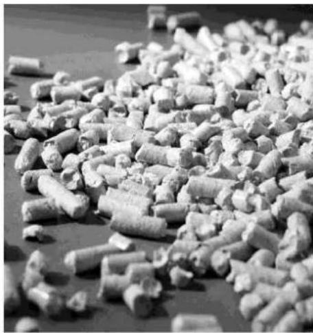
natural_image
Black-and-white photo of a pile of small cylindrical pellets or bricks on a surface (no text or symbols visible)Fuel pellets
natural_image
Close-up of a textured, rectangular object with granular surface (no visible text or symbols)The pellet is obtained by processing the sawdust produced during working wood and timber ( dried wood and paint free. The compactness of the material is guaranteed by the lignin which is contained in the wood itself and allows the production of pellets without the 'use of glues or binders.
The market offers different types of pellets with characteristics that vary based on mixtures of wood used. The diameter varies between 6 and 8 mm, with a standard length between 5 and 30 mm. The pellets of good quality has a density ranging from 600 to more than 750 kg / m3 with a water content that is maintained between 5% and 8% of its weight.
In addition to being an environmentally friendly fuel, as you push the limits of wood residues resulting in a cleaner-burning than that produced with fossil fuels, the pellets also have technical advantages. While a good wood has a calorific value of 4.4 kW / kg (15% RH, after 18 months of seasoning), the pellet is 4.9 kW / kg.
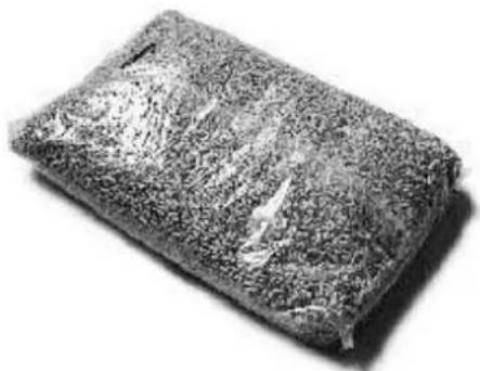
To ensure good combustion, and no power problems, it is imperative that the pellets are stored in a dry place, protected from dirt, and the thermo stove is placed in a place where the conditions are the same, not to generate the same type of problems on the power pellets in the tank. The pellet is usually supplied in 15 kg bags, so storage is very handy.
A good quality pellet ensures good combustion lowering harmful emissions into the atmosphere.

If the fuel is poor, the more often cleaning inside the
grate and the combustion chamber will be required.
The main certifications of quality for pellets in the European
market are
DINplus and Ö-Norm M7135; these ensure respect of:
√ Calorific power: 4.9 kW/kg
√ Water content: max 10% of weight
√ Percentage of ashes: max 0,5% of weight
√ Diameter: 5 - 6mm
√ Length: max 30mm
√ Contents: 100% untreated wood, with no added bonding
substances (bark percentage 5% max)
√ Packaging: in sacks made from ecologically compatible or biologically decomposing material

HANKS strongly recommends using certified fuel in its stoves (DINplus e Ö-Norm M7135).
The use of fuel of inferior quality or not conforming to the specification given above compromises the running of your stove and can therefore lead to the termination of the guarantee and of the manufacturer's responsibility for the product.
HANKS pellet stoves run exclusively on pellets with a diameter of 6 mm (only for Italy) and 6-8 mm (European countries) with lengths that go from 5 mm to 30 mm.
2.2. PRECAUTIONS FOR INSTALLATION

IMPORTANT!
Installation and assembly of the stove must be carried out by qualified personnel.
The stove must be installed in a suitable position to allow the normal operations of opening and ordinary maintenance. The site must be:
- capable of providing the environmental conditions for operation
• equipped with power supply 230V 50 Hz - capable of taking an adequate system for smoke discharge
• provided with external ventilation
• provided with an earth connection complying with CEI
The stove must be connected to a flue pipe or an internal or external vertical duct conforming to current standards UNI 7129 - 7131 9615. The stove must be positioned in such a way that the electrical plug is accessible.

IMPORTANT!
The stove must be connected to a flue pipe or a vertical duct which can discharge the fumes at the highest point of the building. The fumes are however derived from the combustion of wood products, and if they come into contact with or close to walls, they can make dirty marks. Also take care because the fumes are very hot but almost invisible, and can cause burns on contact. The holes for the passage of the smoke pipe and for the intake of air from outside should be made before positioning the stove unit.
text_image
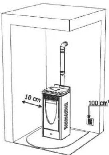
10 cm 100 cm²Example of pellet stove installation
2.3. OPERATING ENVIRONMENT
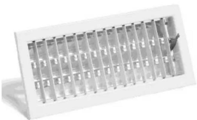
For proper operation, and a uniform distribution of temperature, the stove should be placed in a location with an air flow that guarantees the air needed for combustion of the pellets (should be available approximately 40m^3/h ) according to the installation and the second regulations in the country. The volume of the environment must not be less than 30m^3 . The air must enter through permanent openings on the walls (near the stove) with a minimum of 100 square centimeters. These openings must be made so that they can not be obstructed in any way, and allow
proper airflow. Air can also be taken to ventilate rooms adjacent provided they are equipped with air hose and are not used as a bedroom and bathroom, or where there is no fire hazard such as: garages, sheds, storage of combustible materials, etc., strictly complying with the requirements under current rules. It is absolutely prohibited to installation the stove in bedrooms, bathrooms, and where it is already installed another d heating device without adequate airflow (fireplace, stove, etc..).
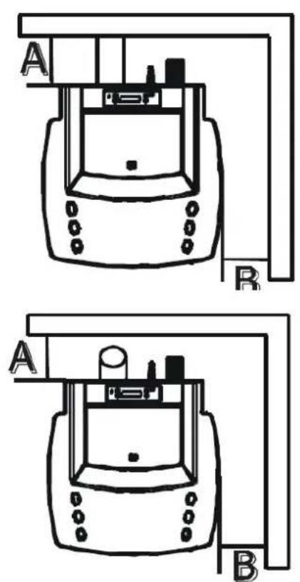
Example of pellet stove installation
where the stove is installed , the stow air flow in sufficient quantity as it is the regular combustion equipment and This can be done by means of perma the walls that give the room to be the outside, ventilation ducts or throu collective. Within this scope , the out stove must have an opening minimum protected by a grid inside and outside must also:
- be communicating directly with the environment
•be protected by a grate, wire mesh
protection, provided it does not reduce the minimum section.
- position in a suitable manner as to prevent it from being obstructed in any way

It is expressly prohibited the placement of the stove in environments
with explosive atmospheres. The floor of the room where the stove will be installed must be sized appropriately to support the weight of the stove itself (which should be considered in addition to the weight of the machine said the same load must be added a maximum of 60 kg for the pellets, and 80 kg for water). When installing, keep a minimum distance from obstacles and not flammable (B) of 25 cm the rear to, lateral (LR) of 25 cm and anterior (C) of 80 cm. In the presence of objects believed to be particularly sensitive such as furniture, curtains, sofas, carpets, etc., greatly increase the distance of the stove from them. In the presence of wooden floor floor-prepare the plan and in accordance with rules in force in the country, on fire prevention.
2.4. CONNECTION TO THE EXTERNAL AIR INTAKE
natural_image
Exterior view of a modern office building (no signage)It is essential that the room can avail of an required by ventilation. openings on ventilated to individual or wall near the 100 cm ^2 , The air intake
installation
other suitable

It is prohibited to connect the air directly to the stove (communicating directly from the outside), to avoid
compromising thermodynamic performance, however it is required that the conditions still guarantee about 50 m^3/h of air replacement, as provided in the current UNI 10683.
2.5. CONNECTION OF SMOKE DISCHARGE PIPE
text_image
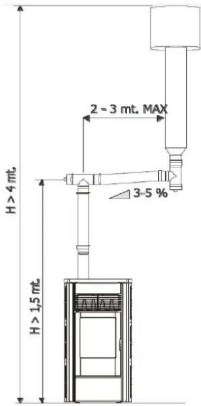
H > 4 mt. 2 - 3 mt. MAX 3-5 % H > 1,5 mt.Example of pellet stove installation
When making the hole for the flue pipe it must be taken into account the possible presence of inflammable materials. If the hole has to go through a wood wall or other thermo labile material, the installer MUST use the Industrial insulated pipe (with min thermal conductivity of 0.07 W / m ° K). The same applies if the stove pipe must go vertical or horizontal sections remain near (min.20cm) to a heat-labile wall. The combustion chamber works in depression, so the exhaust duct for the exhaust fumes will be linked to depression when effective chimney as prescribed.

It should always use pipes and fittings with appropriate seals to ensure
air-tightness in order to avoid possible harmful CO fumes into the environment.

All sections of the exhaust duct must be inspectable and removable to allow for periodic cleaning of the interior, which is necessary for the proper functioning of the system (T-piece with inspection). Position the stove strict accordance with all regulatory requirements and attention to highlighted date.

IMPORTANTE!
All changes direction 90 degrees of the flue gas channel must be prepared if possible with the appropriate fittings to "T" with inspection. It is absolutely forbidden to use a
net at the end of the hose as it can cause serious problems for the proper and safe operation of the stove.
In connection do not use the chimney sections of pipe horizontally, but always the same place at an angle of 5^ minimum to rise, possibly avoiding the use of a 90-degree (you can use upto 3), and use preferably 45^ curves. It is recommended to not use a total length of the pipe diameter 80 mm, greater than 6 m in total.
2.6. CONNECTION TO THE CHIMNEY
text_image
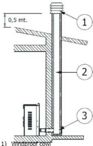
0,5 mt. 1) Windproof cowl 2 32) Flue pipe
3) Inspection
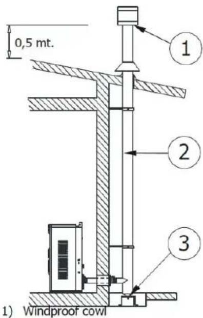
The chimney must have inside dimensions of no more than cm. 20X20 or 20 cm diameter. In the case of larger or poor condition of the chimney (ie: cracks, poor insulation, etc.) it is recommended to insert stainless steel tube in the chimney of a of suitable diameter for its entire length, to the very top. Check with suitable
instruments that there is a minimum draft. Guaranteed 15 Pa. At the bottom of a chimney inspection for periodic inspection and cleaning, which must be done annually. You must ensure that a chimney top is installed according to regulations for wind force.

This type of connection must guarantee of 15 Pa, allows the correct discharge of smoke with a natural draft even if there is no electricity.
2.7. CONNECTION TO AN EXTERNAL FLUE PIPE WITH ISOLATED OR DOUBLE WALL
PELLET BURNING STOVES INSTALLATION AND MAINTENANCE MANUAL
text_image
0,5 mt. 1) Windproof cowl 2 3The external pipe must have minimum internal dimensions of cm. 10X10 or 10 cm diameter. cm, and maximum. 20X20 or 20 cm diameter. Check with appropriate tools that there is a draw of 10 Pa. It must use only, and only pipes insulated (double wall) within the smooth stainless steel (stainless steel flexible tubes are not allowed) fixed to the wall, to prevent, and / or minimize condensation problems. At the bottom of the outer vertical duct an inspection tap for periodic inspections and cleaning to be done annually. You must ensure that the chimney is installed according to wind force.

This type of connection, even in case of momentary power failure, ensuring the evacuation of the fumes.
2.8. CONNECTION TO THE FLUE PIPE
text_image
0,5 mt. 2 - 3 mt. MAX 3-5 % H > 1,5 mt. ① ② ③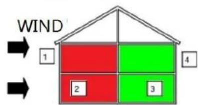
text_image
WIND 1 2 3 41-2=ZONE IN OVER PRESSURE
3-4=ZONE IN DEPRESSION
text_image
MOST FAVOURABLE POSITION LESS FAVOURABLE POSITION WINDHIGH PRESSURE ZONE LOW PRESSURE ZONE
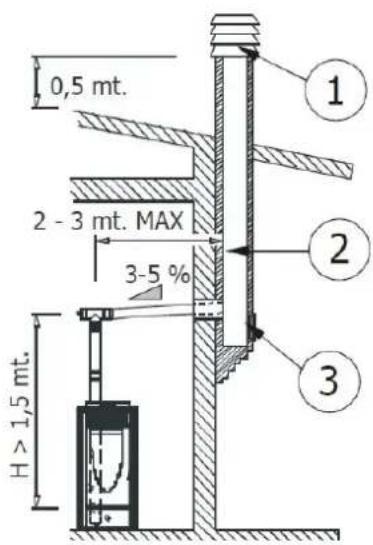
The connection between stove and chimney or flue for the proper operation must not be less than 5% slope in the horizontal sections whose total length should not exceed 1.5 meters. and the vertical by a "T" to another (changing direction) must not be less than 1.5 meters. Check with suitable instruments that there is a minimum draft. of 10 Pa. At the bottom of the chimney inspected for periodic inspections and cleaning, which must be conducted annually.
You must ensure that a chimney is installed according to wind force.

This type of connection, even in case of momentary power failure, ensuring the evacuation of the fumes.
2.9. TROUBLESHOOTING RELATED TO DEFECTS IN THE CHIMNEY FLUE
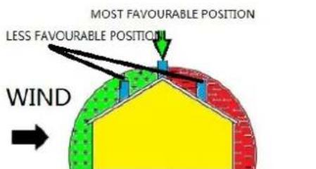
Of all the meteorological and geographical factors that affect the operation of a flue (rain, fog, snow, altitude above sea level, period of insulation, exposure to the cardinal points, etc.) the wind is certainly the most decisive. In fact, besides the thermal depression caused by the difference in temperature between the inside and the outside the chimney, there is another type of depression (or overpressure): the dynamic pressure induced by the wind. An ascending wind always has the effect of increasing depression and then the draft. A horizontal wind increases depression for
proper installation of the chimney. A descending wind always has the effect of relieving depression, sometimes inverting it. In addition to the direction and force of the wind, the position of the flue and the chimney from the roof of the house and the surrounding landscape is important.
The wind affects the operation of the fireplace also indirectly by creating zones overpressure and depression as well as the outside, but inside the home. In areas directly exposed to the wind (2) can create an internal overpressure which can promote the draft of stoves and fireplaces, but may be countered by external overpressure if the chimney is placed on the side exposed to the wind (1). In contrast, in areas opposite to the direction of the wind (3) can create a dynamic depression that comes into competition with the natural thermal depression developed by the fireplace, but can be compensated (sometimes) by placing the exhaust duct from the side opposite to the direction of the wind (4)

IMPORTANT!
The operation of the pellet stove is noticeably sensitive to the conformation and position of the flue which is adopted. Hazardous conditions can only be overcome by suitable setting-up of the stove carried out by qualified HANKS personnel.
2.10. HYDRAULIC CONNECTION

IMPORTANT!
The connection of the stove to the hydraulic system must be made ONLY by qualified personnel and can perform the installation in "ART" and in compliance with all statutory and regulatory provisions in force and not in the country of installation. If the installation of the stove requires interaction with another existing facility complete with another heater (gas boiler, gas boiler, oil boiler, etc ...), is recommended for more qualified personnel who can then be challenged to answer the Full compliance of the system, per the applicable law, and issuing the certificate. HANKS disclaims any liability for damage to persons or property or in the event of failure or improper operation, if not complied with the above warnings, and issued the necessary certificates of compliance enforcement work in an appropriate manner. It is absolutely necessary that the network is designed properly sized to dispose of all the heat flux produced by the stove to avoid raising the temperature inside the boiler.
3. INSTALLATION AND ASSEMBLY
3.1. DRAWINGS AND SPECIFICATIONS
3.1.1. Dimensions of Hydro stoves
B18
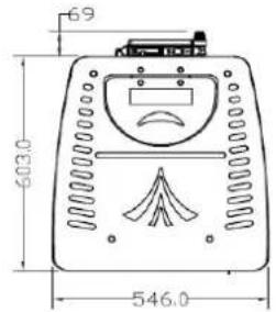
text_image
69 603.0 546.0B18-I
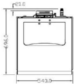
text_image
21.0 696.0 540.0B24
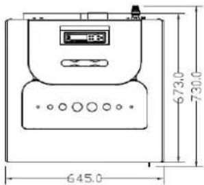
text_image
673.0 730.0 645.0B35
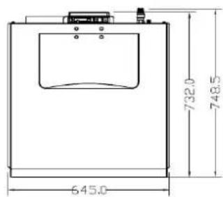
text_image
645.0 732.0 748.5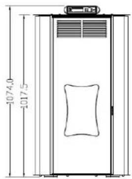
text_image
1074.0 1017.5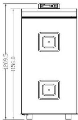
text_image
1209.5 1156.0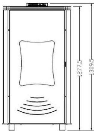
text_image
1277.5 1309.5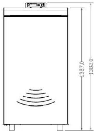
text_image
1327.0 1382.03.1.2. Technical data sheets
| Model NB-B18 NB-B18-I NB-B24 NB-B35 | |||||
| Rating Voltage and Frequency V/HZ | 230V/50HZ | 230V/50HZ | 230V/50HZ | 230V/50HZ | |
| Maximum water pressure Bar 1.5 1.5 1.5 | 1.5 | ||||
| Electronic consumption MAX | W/H | 380 | 380 | 380 | 380 |
| CO emission at 13% oxygen(mg/m3) Max | 185 | 173.6 | 188.3 | 188.3 | |
| CO emission at 13% oxygen(mg/m3) Min | 250.1 | 240 | 211 | 211 | |
| Efficiency Max | % | 93.9 | 95.1 | 95.31 | 92 |
| Efficiency Min | % | 92.4 | 92.4 | 93.9 | 95 |
| Heat Area | M3 | 280 | 340 | 435 | 600 |
| Rating power Max/Min | KW | 18/10 | 18/10 | 24/14 | 35/15 |
| Rating power(water) Max/Min | KW | 12.5/6.1 | 12.5/6.1 | 19.06/10.6 | 19.06/10.6 |
| Thermal power to the environment Max/Min | KW | 4/3.9 | 4/3.9 | 4/3.6 | 4/3.6 |
| ΦPellet | MM | 6 | 6 | 6 | 6 |
| Length of pellet | MM | 30 | 30 | 30 | 30 |
| Hopper capacity | KG | 40 | 40 | 40 | 40 |
| Automatic burning time Max/Min | H | 11/18 | 11/18 | 8/21 | 8/21 |
| Weight | KG | 150 | 180 | 270 | 280 |
| Size(WxHxD) | MM | 545*1017*682 | 525*1156*675 | 630*1278*720 | 645*1378*748 |
PELLET BURNING STOVES INSTALLATION AND MAINTENANCE MANUAL
| Air outlet pipe MM 80 80 80 80 | |||||
| Temperature of the smoke output Max/Min | °C 89.5/80 93/80 95.8/80 | ||||
| Fluc draught pressure Pa 0.1-15 0.1 | -15 0.1 | -15 0.1-15 | |||
3.2. PREPARATION AND UNPACKING
Open the box, unload the stove from the platform with extreme caution, and place the desired location, making sure that it complies with the requirements.
The body, or block should always be handled exclusively by truck in an upright position. You should pay particular attention to the door and its glass to be shielded from shocks that might compromise their integrity.
However, the handling of the products must be done with extreme caution. Unpack the stove near the area where it will be installed.
The materials that make up the package are neither toxic nor harmful, thus do not require special disposal processes. So the storage, disposal or recycling is eventually complete recovery from the end user in accordance with applicable laws.
Do not store the fireplace and coverings without their packaging.
Position the stove, in the correct position that respects faithfully as previously described above, and proceed with the connection to the chimney.
If you connect your stove to a discharge pipe that runs through the back wall (to take in the chimney) pay extreme caution not to force the entrance in any way.
If the flue of the stove is forced or improperly used to lift or placed into position, it will compromise beyond repair, the operation, and GRACE DESIGN is not considered in any way responsible for such a maladroit and/or neglect in the work, so in these conditions any Recovery operations are excluded from warranty.
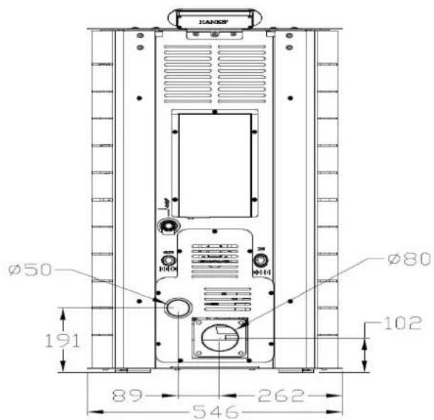
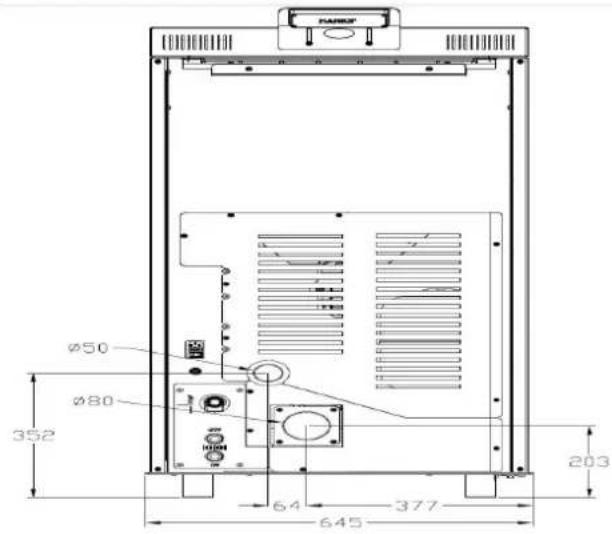
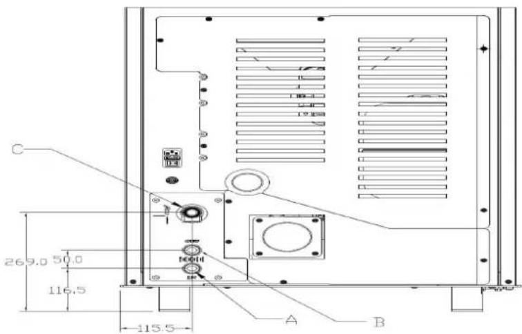
3.3. HYDRAULIC CONNECTION DIAGRAM
For NB-B18 and NB-B18-I
text_image
KANSOP Ø50 191 Ø80 102 89 262 546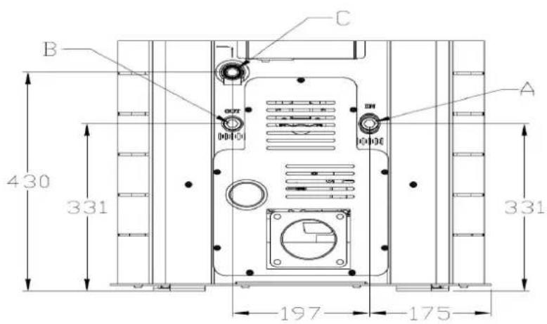
text_image
B C A 430 331 331 197 175A1=Heating water delivery 3/4"M A2=Heating water return 3/4"M C=Safety valve 3 bar - 1/2"F
For NB-B24 AND NB-B35
text_image
MARRS Ø50 Ø80 352 64 645 377 203A1=Heating water delivery 3/4"M A2=Heating water return 3/4"M C=Safety valve 3 bar - 1/2"F
text_image
C 269.0 50.0 116.5 115.5 A B3.3.1. CONNECT TO THE SYSTEM
Carry out the connections to the connections illustrated in the diagram corresponding to the previous page taking care to avoid tension in the pipe and under sizing of the pipes

IMPORTANT!!!
IT IS NECESSARY TO PROVIDE THE PROPER CLEANING THE WHOLE SYSTEM BEFORE YOU CONNECT THE STOVE TO ELIMINATE WASTE AND DEPOSITS
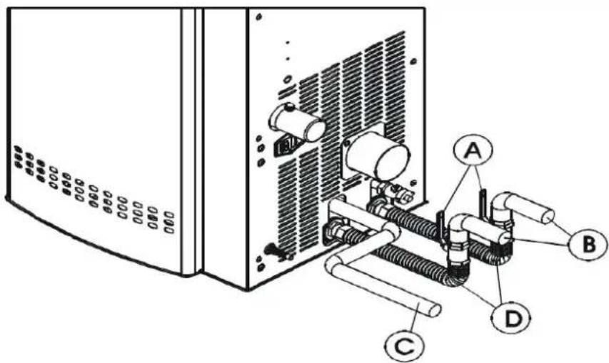
text_image
Technical diagram of a server rack with labeled components A, B, C, and D showing internal piping and ventilation system.$$ A = T A P $$
$$ B = D O M E S T I C S Y S T E M $$
$$ C = \text { PRESSURE DISCHARGE } $$
$$ D = F L E X I B L E P I P E S $$
Always install the heater upstream of the valve gate valve to isolate the same water system or move it move it if necessary, to perform routine maintenance and / or extraordinary. Connect the heater hoses for not using the over-constrain the stove to allow the plant and the light shifts. The pressure relief valve (C) must always be connected to a drain hose. The pipe must be suitable to withstand the high temperature and pressure.
3.3.2. Filling the water network
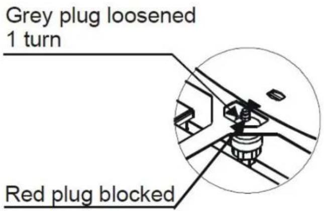
To load of the heater, the heater must be equipped with a tap (optional) with a non-return valve (D) in order to manually fill the network you can use the load tap already on the boiler on the stove.
During that operation, the outlet of any air in the system is guaranteed by the present automatic vent under the top. To guarantee that the valve discharges air, it is recommended to loosen the grey tap and leave the red tap locked (refer to fig.).

The filling pressure during cold status should be 1 bar.
If during operation the system pressure drops (due to evaporatic the gas dissolved in water) to values less
than the minimum indicated above, the User shall, acting on the from the load back to the initial value.
For optimal operation of the stove in a operation (hot), the pressure must be 1.5 bar. Do not exceed 2
bar. At the end of the operation always close the filling tap.
3.3.3. Water characteristics
The characteristics of the water for filling the plant, are very im to avoid the deposition of minerals and the creation of deposits the piping within the boiler and heat exchangers. Therefore it is advised to check with your plumber / fitter the following characteristics:
- Hardness of water circulating in the system to remedy any problems and limestone deposits especially in the hot water heat exchanger. (> 25 ° French
- Installing a water softener (if the water hardness is > 25 ° French)
- Fill the system with treated water (demineralized)
text_image
Grey plug loosened 1 turn Red plug blockedVent valve under the top
- Any set of a circuit condensation.
- Installation of hydraulic shock absorbers to avoid the phenomenon of "water hammer" along the fittings and pipes.

For those with very large systems (with large water content) or who require frequent replenishment of the plants
in the plant to install water softeners, especially because the scale significantly reduce the thermal conductivity!
3.4. KIT WATER PRODUCTION
All thermo stoves are equipped with HANKS kit for the production of hot water characterized by:
- Plate heat exchanger
• 3-way diverter valve, electric motor-driven
• Electrical Flow meter - stainless steel finned pipes and fittings for connecting
- Pressure valve
The kit has the task of heating hot water from the water line of the house. At a time when there is hot water demand by opening a tap, the internal flow-meter commands the diverter valve to convey the hot water contained inside the boiler, to the plate heat exchanger. The hot water temperature will depend on the water temperature inside the heater, with approximation, is calculated by removing 10^ -15°C to the value read on the control panel of the heater (boiler water temperature). For proper lifetime operation of the heat exchanger plates, it is necessary to know the hardness of your water to prevent fouling, and to block the exchange.

3.5. EXAMPLE OF INSTALLATION DIAGRAMS
The diagrams below are merely indicative. For a proper connection, always follow the notes of the plumbing and heating installer with proven experience. The hydraulic system must meet the mandatory regulations of the place, region or state. The installation, testing and certification of operation must be performed only by authorized personnel, with the issue of certification that the work has been completed in a “state of art” performance, attesting the conformity of the work in compliance with laws and regulations. GRACE DESIGN disclaims any responsibility in case of non-compliance to the above, especially in the absence of proof of certification work in a “STATE OF ART” execution.
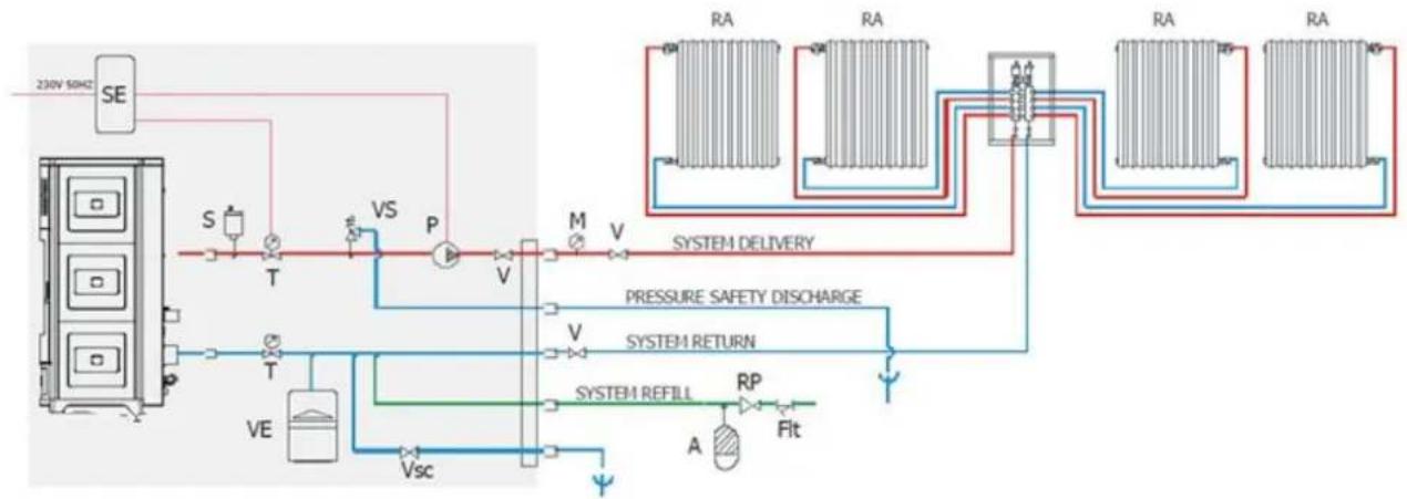
3.5.1. INSTALLATION DIAGRAM FOR HEATING SYSTEM WITH DOMESTIC HOT WATER KIT(SUITE/CLUB/MUSA)
flowchart
graph TD
    A["230V 50Hz SE"] --> B["S"]
    B --> C["T"]
    C --> D["VS"]
    D --> E["P"]
    E --> F["V"]
    F --> G["M"]
    G --> H["V"]
    H --> I["SYSTEM DELIVERY"]
    I --> J["RA"]
    I --> K["RA"]
    I --> L["RA"]
    I --> M["RA"]
    I --> N["RA"]
    O["VE"] --> P["T"]
    P --> Q["Vsc"]
    Q --> R["SYSTEM REFILL"]
    R --> S["RP"]
    S --> T["A"]
    T --> U["Fit"]
    U --> V["Pressure Safety Discharge"]
    V --> W["SYSTEM RETURN"]
    W --> X["VA"]
    X --> Y["VA"]
    Y --> Z["VA"]
    Z --> AA["VA"]
CONFIGURATION: STAR/EGO/SUITE/CLUB/MUSA WITH DOMESTIC HOT WATER KIT SYSTEM OF SYSTEM WITH CLOSED TANK ONLY FOR HEATING BY MEANS OF RADIATORS
SIGNATURFORKLARING:
| SE | Electronic card | VD | One-way valve | C | Methane gas boiler | A | Pounding absorber |
| S | Automatic vent | T | Measurement of boiler temperature | B | Boiler | RP | Pressure reduction valve |
| M | Pressure gauge | VE | Expansion tank, 1.5 bar of 6 l | BA | Storage boiler | Vsc | Boiler/system discharge valve |
| VS | Vent valve, 3 bar | W | 3-way motorized valve | RA | Radiators | Fit | System filter |
| V | Valve | SC | Plate heat exchanger | PR | Radiant panels | Add | Softener |
| P | Pump | F | Flow switch | PS | Solar panels |
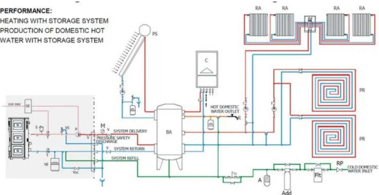
3.5.2 HEATING INSTALLATION IN COMBINATION WITH A STORAGE TANK
PERFORMANCE:
HEATING WITH STORAGE SYSTEM PRODUCTION OF DOMESTIC HOT WATER WITH STORAGE SYSTEM
flowchart
graph TD
    A["HEATING WITH STORAGE SYSTEM PRODUCTION OF DOMESTIC HOT WATER WITH STORAGE SYSTEM"] --> B["BA"]
    B --> C["SO Box"]
    B --> D["Pressure Safety Discharge"]
    B --> E["SYSTEM RETURN"]
    B --> F["SYSTEM REFILL"]
    B --> G["Hot Domestic Water Outlet"]
    G --> H["PR"]
    H --> I["COLD DOMESTIC WATER INLET"]
    I --> J["Add"]
    J --> K["Fit"]
    K --> L["RP"]
    L --> M["PR"]
    M --> N["Hot Domestic Water Outlet"]
    N --> O["PA"]
    O --> P["PS"]
    P --> Q["PEaking System"]
    style A fill:#f9f,stroke:#333
    style B fill:#ccf,stroke:#333
    style C fill:#cfc,stroke:#333
    style D fill:#fcc,stroke:#333
    style E fill:#cff,stroke:#333
    style F fill:#ffc,stroke:#333
    style G fill:#fcf,stroke:#333
    style H fill:#cff,stroke:#333
    style I fill:#cfc,stroke:#333
    style J fill:#cfc,stroke:#333
    style K fill:#cfc,stroke:#333
    style L fill:#cfc,stroke:#333
    style M fill:#cfc,stroke:#333
    style N fill:#cfc,stroke:#333
    style O fill:#cfc,stroke:#333
    style P fill:#cfc,stroke:#333
    style Q fill:#cfc,stroke:#333
CONFIGURATION: STAR/EGO/SUITE/CLUB/MUSA WITHOUT DOMESTIC HOT WATER KIT COMBINED WITH STORAGE SYSTEM WITH BOILER AND SOLAR PANELS SYSTEM DIAGRAM WITH CLOSED TANK FOR HEATING WITH RADIATORS OR RADIANT PANELS AND FOR THE PRODUCTION OF DOMESTIC HOT WATER
SIGNATURFORKLARING:
| SE | Electronic card | VD | One-way valve | C | Methane gas boiler | A | Pounding absorber |
| S | Automatic vent | T | Measurement of boiler temperature | B | Boiler | RP | Pressure reduction valve |
| M | Pressure gauge | VE | Expansion tank, 1.5 bar of 6 l | BA | Storage boiler | Vsc | Boiler/system discharge valve |
| VS | Vent valve, 3 bar | W | 3-way motorized valve | RA | Radiators | Flt | System filter |
| V | Valve | SC | Plate heat exchanger | PR | Radiant panels | Add | Softener |
| P | Pump | F | Flow switch | PS | Solar panels |
3.5.3. HEATING INSTALLATION DIAGRAM IN COMBINATION WITH A BOILER
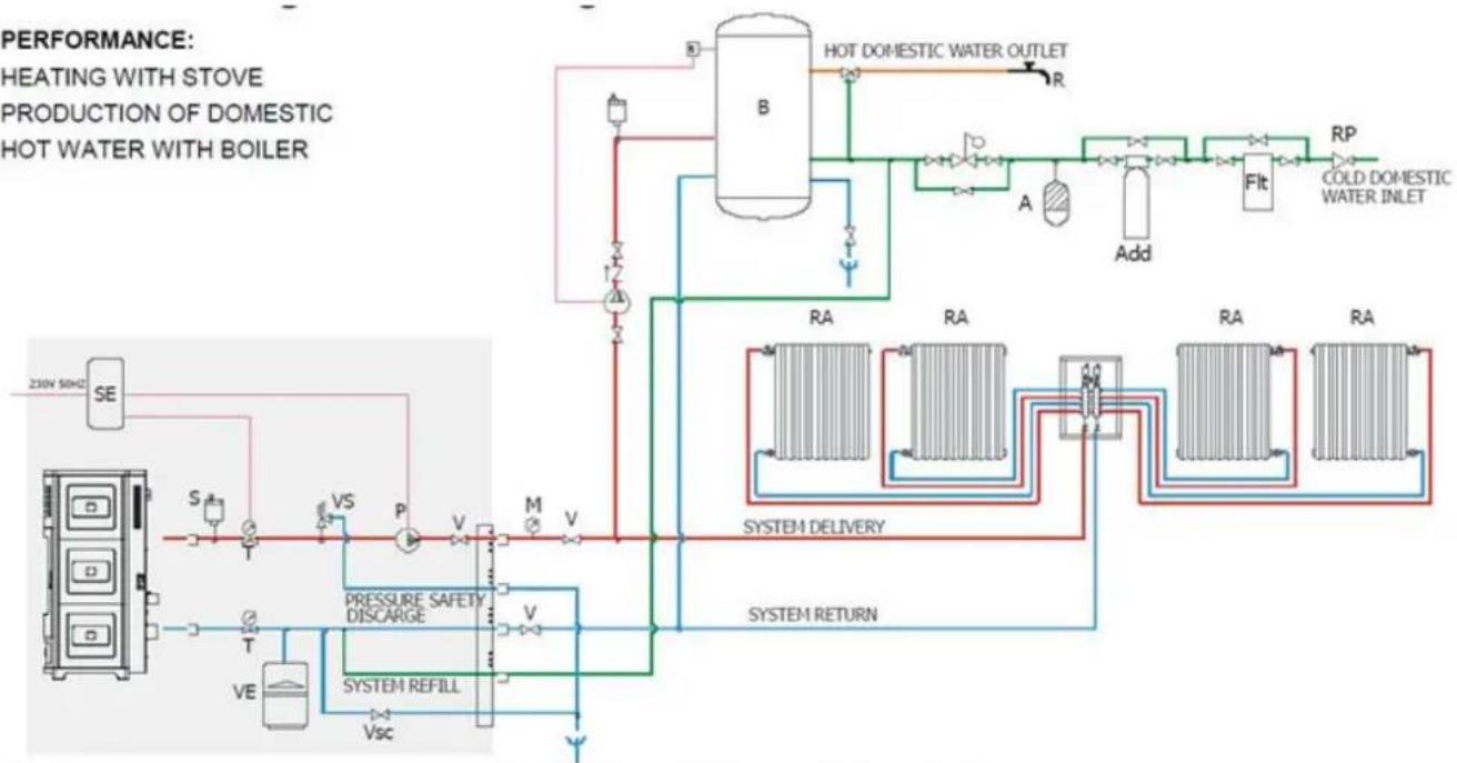
flowchart
graph TD
    A["HEATING WITH STOVE PRODUCTION OF DOMESTIC HOT WATER WITH BOILER"] --> B["230V 50Hz SE"]
    B --> C["S"]
    C --> D["T"]
    D --> E["VE"]
    E --> F["P"]
    F --> G["M"]
    G --> H["V"]
    H --> I["Vsc"]
    I --> J["SYSTEM REFILL"]
    J --> K["PRESSURE SAFETY DISCARGE"]
    K --> L["S"]
    L --> M["T"]
    M --> N["VS"]
    N --> O["P"]
    O --> P["M"]
    P --> Q["V"]
    Q --> R["V"]
    R --> S["Pressure Return"]
    S --> T["SYSTEM DELIVERY"]
    T --> U["RP"]
    U --> V["COLD DOMESTIC WATER INLET"]
    V --> W["A"]
    W --> X["Add"]
    X --> Y["Flt"]
    Y --> Z["Hot DOMESTIC WATER OUTLET"]
    Z --> AA["R"]
    AA --> AB["B"]
    AB --> AC["HOT DOMESTIC WATER OUTLET"]
CONFIGURATION: STAR/EGO/SUITE/CLUB/MUSA WITHOUT DOMESTIC HOT WATER KIT COMBINED WITH BOILER HEATING WITH STORAGE SYSTEM PRODUCTION OF DOMESTIC HOT WATER WITH STORAGE SYSTEM
SIGNATURFORKLARING:
| SE | Electronic card | VD | One-way valve | C | Methane gas boiler | A | Pounding absorber |
| S | Automatic vent | T | Measurement of boiler temperature | B | Boiler | RP | Pressure reduction valve |
| M | Pressure gauge | VE | Expansion tank, 1.5 bar of 6 l | BA | Storage boiler | Vsc | Boiler/system discharge valve |
| VS | Vent valve, 3 bar | W | 3-way motorized valve | RA | Radiators | Flt | System filter |
| V | Valve | SC | Plate heat exchanger | PR | Radiant panels | Add | Softener |
| P | Pump | F | Flow switch | PS | Solar panels |
- Operations Instructions - Quick reference guide
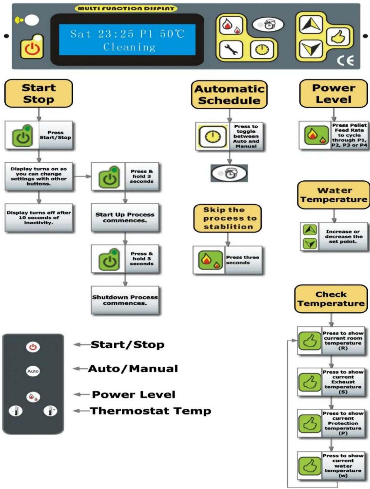
flowchart
graph TD
    A["Start Stop"] --> B["Press Start/Stop"]
    B --> C["Display turns on so you can change settings with other buttons."]
    C --> D["Display turns off after 10 seconds of inactivity."]
    D --> E["Start Up Process commences."]
    E --> F["Press & hold 3 seconds"]
    F --> G["Shutdown Process commences."]
    G --> H["Check Temperature"]
    H --> I["Press to show current room temperature (R)"]
    I --> J["Press to show current Exhaust temperature (S)"]
    J --> K["Press to show current Protection temperature (P)"]
    K --> L["Press to show current water temperature (w)"]

    M["Automatic Schedule"] --> N["Press to toggle between Auto and Manual"]
    N --> O["Power Level"]
    O --> P["Press Pellet Feed Rate to cycle through P1, P2, P3 or P4"]
    P --> Q["Water Temperature"]
    Q --> R["Increase or decrease the set point."]

    S["Start/Stop"] --> T["Auto/Manual"]
    T --> U["Power Level"]
    U --> V["Thermostat Temp"]
PELLET BURNING STOVES INSTALLATION AND MAINTENANCE MANUAL
Switching on / switching off
The heater switching on and switching o

performed through the ON/OFF
After switching on, the message,
"CLEANING" will be shown on first, in to clean the fire pot.
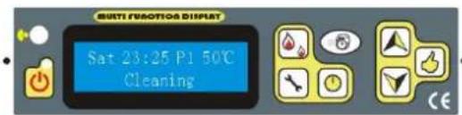
text_image
Multi-Functional Display Sat 23:25 P1 50°C Cleaning
In the same way, push, then at the switching off Period, the message shows:
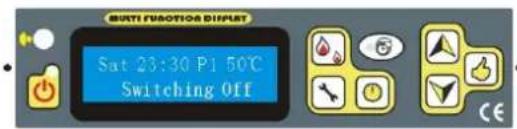
text_image
MULTI FUNCTION DISPLAY Sat 23:30 P1 50°C Switching Off CE
After the temperature in the stove is cold enough, finally, the phrase' GOODBYE' is displayed.
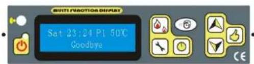
text_image
AUTO VIACITOR SWITCH Sat 23:24 P1 50°C GoodbyeThe switching on Stage, which has the dura about 5-15 minutes, are necessary to the res to carry the pellets at the switching on temperature, (depends from the heater). The switching on procedure is showed from a pa set showed in the display as previous one then:
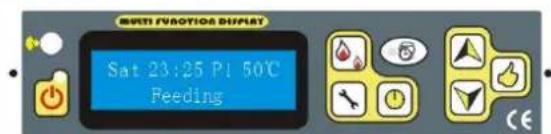
text_image
METH FROSION DUPLET Sat 23:25 P1 50°C Feeding
text_image
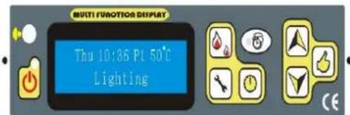
MULTI FUNCTION DISPLAY Thu 10:36 PL 50°C LightingThirdly, After second phase is showed from t message 'FEEDING'. In this phase are perfo the chimney verification operations and the p will be loaded in the melting pot. The succ phase will be showed from the inscription "Lighting". This state remains up to when the smokes temperature doesn't exceed the planned threshold.
When the Lighting phase is finished, some minutes will spend necessary for the flame stabilization. This phase is showed from the message “STABILIZATION” which finishes after some minutes going up at the work
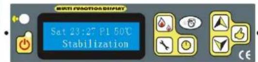
text_image
SAT 23:27 P1 50°C Stabilization!! ATTENTION !!
During the flame switching off phase and exchanger cooling, Normally it isn't allowed to switch on again the heater up to the operation end; this state is highlighted from the message 'SWITCHING OFF'
PELLET BURNING STOVES INSTALLATION AND MAINTENANCE MANUAL
HOWEVER, It is possible to switch off the heater in every functioning phase. The switching off performs
pressing the key ON/OFF for two seconds, make sure the stove is under your eyes, until its "Stabilisation", After push the button, then the phrase "Cooling" comes
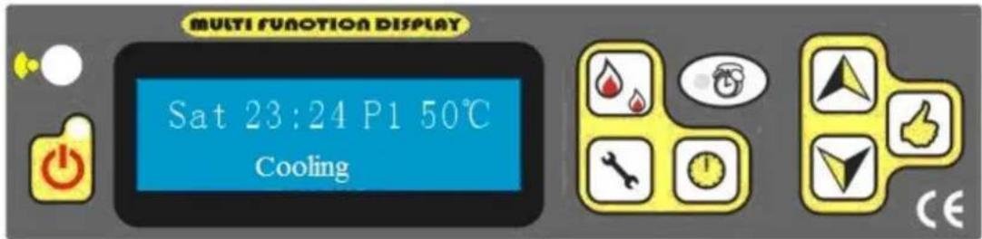
text_image
MULTI FUNCTION DISPLAY Sat 23:24 P1 50°C CoolingAfter the stove's temperature falling down, the stove starts again, Cleaning-feeding-lighting-stabilization.
How to make the stove immediately skip the process to Stabilization During the first several stages the flame is ok and/or the stove can work properly?
Push for 3 seconds, and then it will turn on Stabilization directly.
when you
!! ATTENTION !!
If the heater is switched off, the flame will continue to be present up to the fuel exhaustion contained in the pot, this phase will manage in automatic way both fans and it will have the duration up to 5-8 minutes.
The switching off phase is displayed from the message “SWITCHING OFF” present up to the end of the operation.
Whether the heater is switched or not, on the display will display the hour, the power, and the planned set t
Note: If the new stove, when its first time using, it is necessary to put a hand of pellet to hand.
the fire po
Note: if the ignition is failure, the thermal control will shut off the stove automatically. Meanwhile, E2 (Error for the ignition failure), will be turned on the display, If want to restart it again, Please Check the stove as
cleaning the fire pot. After that, you have to push and start again.

clean the Phrase E2. Follow the above process to ignite
PELLET BURNING STOVES INSTALLATION AND MAINTENANCE MANUAL
FLAME POWER VARIATION
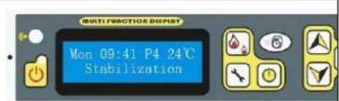
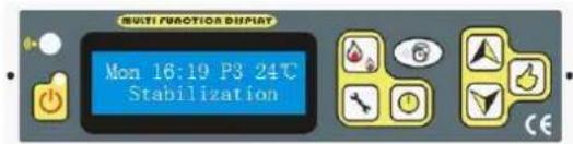
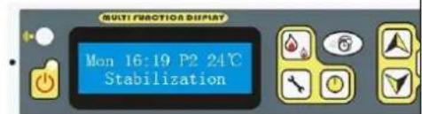
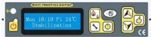
Depending on the heating desire, fuel intake quantity can be adjusted from few to large by the fuel intake B. For example,
Pressing the key the feed quantity can be changed, the display shows the selected power.
text_image
MULTI FUNCTION DEPUT Mon 09:41 P4 24°C StabilizationMINIMUM POWER P4
text_image
Multi FUNCTION DISPLAY Mon 16:19 P3 24°C StabilizationP3
LOW POWER
text_image
Multi FRACTION DISPLAY Mon 16:19 P2 24°C StabilizationMEDIUM POWER P2
text_image
MULTI FANOTIA DISPLAY Mon 16:19 P1 24°C StabilizationPOWER PI
MAXIMUM
ECO STAGE
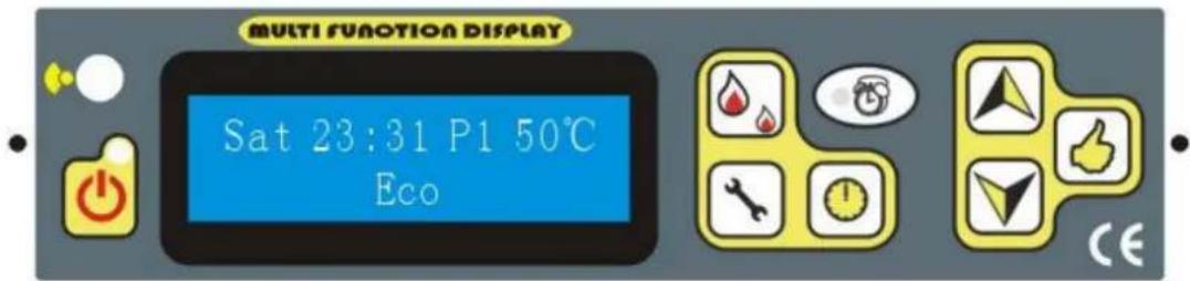
If the room temperature exceeds the set out temperature, automatically the stove is stopped Eco1 or turns to minimum power in order to save energy Eco2. It shows like following:
text_image
MULTI FUNCTION DISPLAY Sat 23:31 P1 50°C EcoAfter the room temperature drops down, and below the set out temperature (3degrees), it automatically, switch in on again or come back to the previous Power level. Later how to select these two functions will be shown.
Automatic and manual SELECTING

Pressing the keys, The light shown on the following, will be on/off. If the light is on, it shows that automatic program is selected. Otherwise it is manual.

DESIRED TEMPERATURES SETTING
Pressing the keys , on the display The temperature is selecting.


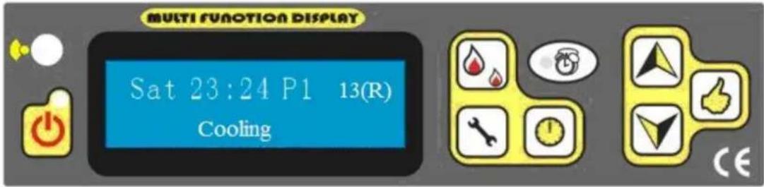
How to Check the Room temperature, Exhaust (Smoke) Temperature, Safety (Protection) Temperature
located under the hopper. By Push button

The number with "R" is the temperature for room.
The number with "S" is the temperature for the Smoke
The number with "P" is the temperature for the Protection.
The number with "w" is the temperature for water
For example:
text_image
MULTI FUNCTION DISPLAY Sat 23:24 P1 13(R) CoolingIt means that the room temperature is 13 degree.
3.) How to set details
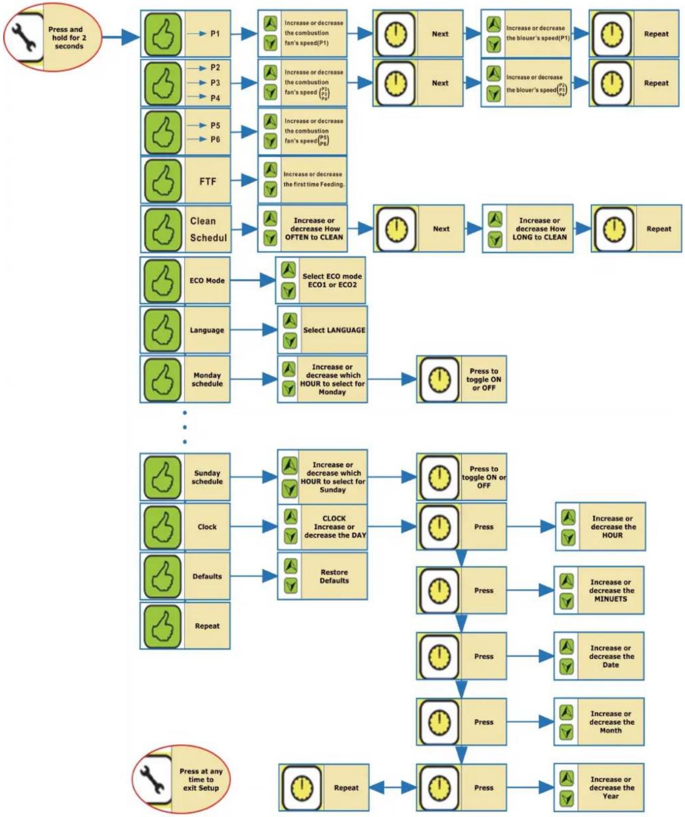
Setup - Quick reference guide
flowchart
graph TD
    A["Press and hold for 2 seconds"] --> B["👍 → P1"]
    B --> C["Increase or decrease the combustion fan's speed(P1)"]
    C --> D["Next"]
    D --> E["Increase or decrease the blouer's speed(P1)"]
    E --> F["Repeat"]
    A --> G["👍 → P2 → P3 → P4"]
    G --> H["Increase or decrease the combustion fan's speed(P2) / (P3) / (P4)"]
    H --> I["Next"]
    I --> J["Increase or decrease the blouer's speed(P2) / (P4)"]
    J --> K["Repeat"]
    A --> L["👍 → P5 → P6"]
    L --> M["Increase or decrease the combustion fan's speed(P5) / (P6) / (P6)"]
    M --> N["Increase or decrease the first time Feeding."]
    N --> O["Next"]
    O --> P["Increase or decrease How OFTEN to CLEAN"]
    P --> Q["Next"]
    Q --> R["Increase or decrease How LONG to CLEAN"]
    R --> S["Repeat"]
    A --> T["FTF"]
    T --> U["Increase or decrease how often to clean"]
    U --> V["Next"]
    V --> W["Increase or decrease How LONG to CLEAN"]
    W --> X["Repeat"]
    A --> Y["Clean Schedule"]
    Y --> Z["Select ECO mode ECO1 or ECO2"]
    Z --> AA["ECO Mode"]
    AA --> AB["Language"]
    AB --> AC["Select LANGUAGE"]
    AC --> AD["Monday schedule"]
    AD --> AE["Increase or decrease which HOUR to select for Monday"]
    AE --> AF["Press to toggle ON or OFF"]
    AF --> AG["..."]
    AG --> AH["Sunday schedule"]
    AH --> AI["Increase or decrease which HOUR to select for Sunday"]
    AI --> AJ["Press to toggle ON or OFF"]
    AJ --> AK["Clock"]
    AK --> AL["CLOCK Increase or decrease the DAY"]
    AL --> AM["Press"]
    AM --> AN["Increase or decrease the HOUR"]
    AN --> AO["Defaults"]
    AO --> AP["Restore Defaults"]
    AP --> AQ["Press"]
    AQ --> AR["Increase or decrease the MINUETS"]
    AR --> AS["Repeat"]
    AG --> AT["Posts at any time to exit Setup"]
    AT --> AU["Repeat"]
    AU --> AV["Press"]
    AV --> AW["Increase or decrease the Month"]
    AW --> AX["Increase or decrease the Date"]
    AX --> AY["Press at any time to exit Setup"]
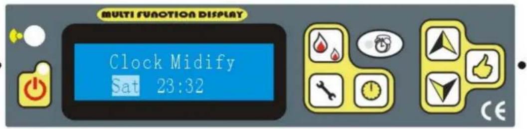
CLOCK SETTING
Press the key, the time can be amended:
text_image
MULTI FUNCTION DISPLAY Clock Midify Sat 23:32You can select week or time by keys ,
also using to change the day or time, to save the correct data by press and move to next stage.
CLEANING SETTING
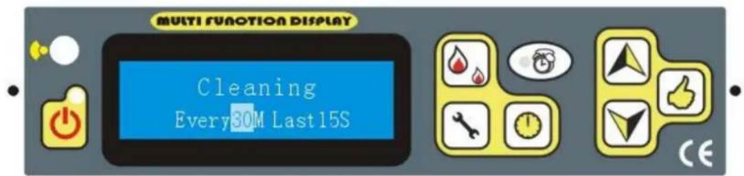
you can adjust the time of cleaning during the operation---- "every X mins, last Y" Seconds to cleaning the burning pot by the key
For example every 30mins Last 15 s
text_image
MULTI FUNCTION DISPLAY Cleaning Every30M Last15STIMER SETTING

Press the key into next stage: On the display the following wording will appear
text_image
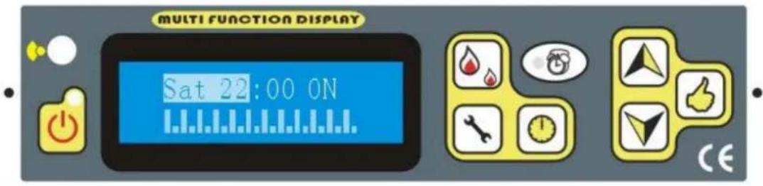
MULTI FUNCTION DISPLAY Sat 22:00 ON CEWith this function you program the heater for a weekly programming, associating the s and the switching off at the pre fixed timetables. You can program daily switching on off for the whole week.
By keeping pressing the key, you will found the attached instruction above,
Then you can press to choose week days
By pressing, to select hours, then press to decide the hour on or Off.
On the above line it is showed the day which is programming, the hour with the fun. On the below line the programmed hour are displayed.
- Lower one means off, taller on means on, which also shows on superior line
LANGUAGE SETTING

By keeping pressing the key it will appear the following words:

text_image
MULTI FUNCTION DISPLAY Language EnglishWith this function you can select language. By pressing the key .

the

ECO modSETTING
By keeping pressing the

key it will appear the following words:
text_image
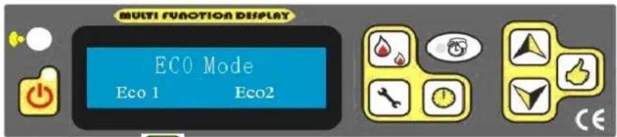
MULTI FUNCTION DISPLAY ECO Mode Eco 1 Eco2Pressing the key, to select the Mode 1 or Mode 2, Mode 2 is for turning to minimum Power, while mode 1 is for stopping the stove.

Restore Defaults select
Keeping pressing the key it will appear the following words

text_image
MULTI FUNCTION DISPLAY Restore Defaults ? Yes NoBy , you can choose Yes, Or No. “Yes”- go back factory setting “NO” - use the data you changed.
Pressing the key the programming will finish.
!! ATTENTION !!
******************************************************************************************
PELLET BURNING STOVES INSTALLATION AND MAINTENANCE MANUAL
text_image
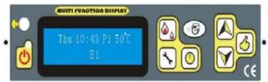
Multi FUNCTION DISPLAY Thu 10:43 P1 50°C E1It means fire put out automatically during the operation, when the exhaust gas temperature is below 40-45 degree.
Such as: 1. There has no fuel at hopper. 2. Auger motor is broken and stop feeding fuel.
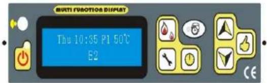
text_image
MULTI FUSOTOR DISPLAY Thu 10:35 P1 50°C E2It means Igniter failure at the beginning.
Such as: 1. there have clinkers in fire pot.
-
The fire pot has not put right.
-
The switch which is located beside the combustion fan to test the exhaust gas temperature sensor, is broken,
-
The igniter is broken
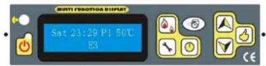
text_image
BUTI FAVOTIO DISPUT Sat 23:29 P1 50°C E3It means there is earthquake during the operation time. or You tilt the stove. Only for the Japan version
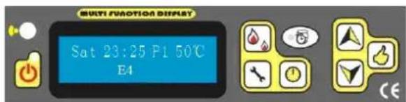
text_image
MULTI FUNCTION DISPLAY Sat 23:25 P1 50°C E4Problem for the temperature sensor.
Unplug or broken or water temperature is too high (This function only for the pellet stove with hot water)
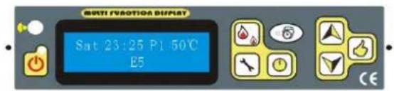
text_image
MULTI FRACTIONA DISPLAY Sat 23:25 P1 50°C E5It means that there are some problems with vacuum Switch.
Such as door has not been closed properly; Combustion fan's speed cannot Speed up; There is some leakage about the stove or exhaust pipe is blocked and so on.
text_image
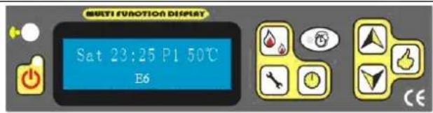
MULTI FUNCTION DISPLAY Sat 23:25 P1 50°C E6It means that the high temperature sensor, which is located below the hopper, has some problem, Such as: 1. the switch is broken,
- The temperature is too high that the stove runs not properly
text_image
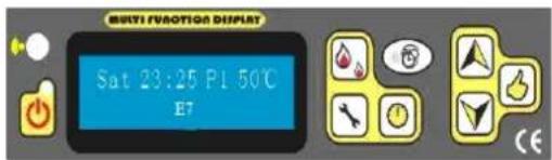
MULTI FLOOTION DISPLAY Sat 23:25 PL 50°C E7During the operation, the stove is interrupted by electronic cut.
text_image
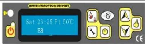
BUTI FICTION DEPUT Sat 23:25 P1 50°C E8It means you need to cleaning the stoves.
check everything is fine, you can press to delete the Error code
!! ATTENTION !!
If showing following words when you start the stove, such as:

It means temperature sensor 1(exhaust temperature sensor) is short-circuit.
gas It means temperature sensor 1 is open-circuit.
It means temperature sensor 2 (safety temperature sensor below the hopper) is short-circuit.
It means temperature sensor 2 is open-circuit.
It means temperature sensor 3(sensor for It means temperature sensor 3 is open-circuit. testing the room temperature, which is located on the rear panel) is short-circuit.
4. )Safety
POWER FAILURE
After the power failure, the display will be show E7. If short power failure, you can do manually goes by "Stabilization" by Clear the E7 by "okay button", restarting the stove and then keeping pressing 3 second of "fire button"
On power failure a small amount of smoke may be emitted. This does not last for more than three to five minutes and does not represent a safety risks.
POWER INPUT SOCKET (contains the main fuse)
ELECTRIC EXCESS-CURRENT SHUT OFF
The device is protected against excess current by a main fuse (on the rear of the device),
The following is a list of main components and their functions
IGNITER
The STOVE comes equipped with an automatic igniter for lighting the fuel when the stove is in feeding and lig
VACCUM SWITCH
The STOVE has a vacuum switch located behind the left door, fastened to the base. If a low pressure is create firebox by a leak, opening the front door, a blocked flue, or unsealed ash drawer(some model), the vacuum swit sense it and cause the stove to go into a shutdown mode by showing E5.
AUGER AND AUGER MOTOR
The 2 RPM auger motor turns the auger, lifting pellets up the auger tube. The pellets are then dropped down a tube and into
the firepot. The auger motor is controlled by the control board.
PROTECT TEMPERATURE SENSOR TO AVOIDOVERHEATING
A safety temperature switch switches the stove off automatically if it overheats,. After the stove has cooled meanwhile it shows E6. Whether the heating operation is continued or not depends on the remaining ember fire pan. After you remove the Error Code by "Okay button", If re-ignition does not occur when the fuel supply
recommences, then the out of operation program (cleaning, lag phase) is carried out. According to the pre the stove must be re-started.
CAUTION: If overheating has occurred then maintenance or cleaning work must be carried out.
EXHUASTED TEMPERATURE SENSOR FUNCTION AS LOW TEMPERATURE SWITCH OFF
If the stove cools down below a minimum temperature, then the stove will switch off. This switch off car pre-heating is too slow.
5. MAINTENANCE AND CLEANING

ATTENTION!
All cleaning of all parts must be carried out with the stove completely cold and unplugged.
The stove does not need much maintenance if used with certified quality pellets.
5.1. DAILY OR WEEKLY CLEANING PERFORMED BY THE USER
natural_image
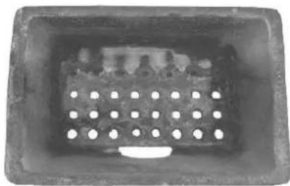
Close-up of a rectangular metal component with a perforated interior (no text or symbols visible)Example of clean grate
natural_image
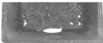
Close-up of a dark rectangular object with a small white hole and granular texture (no text or symbols visible)Example of dirty grate
Clean the ash F" and any deposits in the brazier that could clog the air passage holes.
In case of pellets running out in the tank or of a failed ignition alarm (E2), there could be unbent pellets in the brazier. Always empty the residue in the brazier before each ignition.

REMEMBER THAT ONLY A CORRECTLY POSITIONED AND CLEAN BRAZIER
CAN GUARANTEE IGNITION AND OPTIMAL OPERATION OF YOUR PELLET PRODUCT. IF IGNITION FAILS (E2), IT IS IMPORTANT TO REMOVE THE PELLETS LEFT IN THE BRAZIER AFTER REPEATING THE IGNITION OPERATION.
For the brazier to be cleaned properly, remove it from its housing completely and thoroughly clean all the holes and the grate on the bottom. If good quality pellets are used, you will normally only need to use a brush to restore the optimal operating conditions of the
component.
5.1.2. Check every 2/3 days
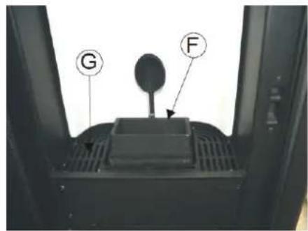
The frequency of cleaning depends on the type of installation/connection to flue pipe (e.g. more frequent with horizontal connection, less frequent with vertical connection), on the number of working hours, level of power and fuel used. Clean and empty the ash tray" being careful with hot ash.
The ash must be completely cold for a vacuum cleaner to be used to rem it. Only use models suited to sucking ashes recommend emptying the ash pa at intervals of no more than 2 or 3 days.
text_image
G FCleaning the ash collection compartment
natural_image
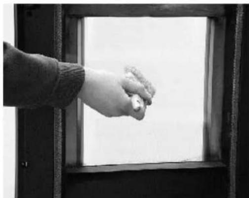
Black-and-white photo of a hand opening a window with a small object near the top (no text or symbols visible)Cleaning the glass
Once the operation is finished, reinsert the ash pan below the grate making sure it is inserted properly.
5.1.3. Cleaning the glass
For cleaning the ceramic glass, the use of a dry brush is recommended, or if it is very dirty, the special spray detergent, applying a small quantity then cleaning with a cloth.

ATTENTION!
Do not use abrasive products and do not spray the cleaning product on the glass of the painted parts or on the gaskets of the fire door (ceramic fiber cord)
5.1.4. Cleaning of stainless steel and satin-finish surfaces
Normally these surfaces do not need to be treated, but if they do, avoid cleaning them with abrasive materials. For surfaces in stainless and satin brushed steel we recommend cleaning with a paper towel or a clean dry cloth moistened with a detergent based on non-ionic surfactants (< 5%). A spray glass cleaner may be used.
5.1.5. Cleaning of painted parts
Do not clean the painted parts with wet rags when the unit is in operation or hot to prevent thermal shock to the paint which may cause it to detach. Do not use abrasive or aggressive products or materials. Clean with damp cotton or paper towels.

The silicon paints used on HANKS products possess technical characteristics that make them resistant to very high temperatures. There is however a physical limit (380°-400°) beyond which the paint begins to fade or (over 450°) to vitrify; it may then flake and detach from the steel surface. If this happens, it means that temperatures have been
text_image
Technical diagram of an internal device with labeled components including coils, connectors, and a control panel.reached that are far above those at which the unit should operate properly.
5.2. CLEANING TO BE PERFORMED BY SPECIALIZED TECHNICIAN
5.2.1. Cleaning the heat exchanger and the pipe unit
Halfway through the winter, but especially in the spring you will need to clean the compartment where discharge smoke passes. This cleaning must be done in order to remove all combustion residues before time and humidity let them harden and make them difficult to remove.
5.2.1.1. CLEANING THE EXCHANGER AND PIPE UNIT (EGO/STAR)
CLEANING THE UPPER COMPARTMENT
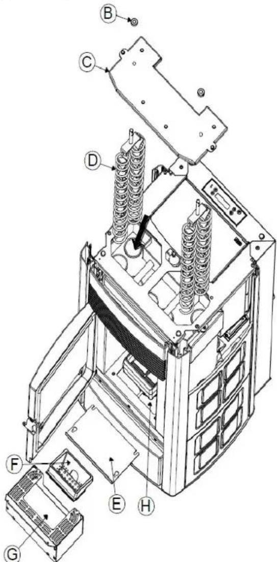
When the stove is cold, remove the top, remove the ceramics/sides as described in section.3.3., loosening the relative fastening screws before removing the drivers“B” and then remove the boiler cover “C”. At this point, remove the turbulators “D” and using a rigid rod or a bottle brush, clean the internal pipe unit and the turbulators, removing all of the accumulated ash. Check the cover gasket and replace it if necessary.
ATTENTION: It is advisable to carry out the cleaning of the upper exchanger at the end of the season and possibly by an authorised HANKS technician in order to replace the gasket that
Figure 16 - Cleaning the pipe unit, turbolator and lower compartment (EGO/STAR)
is below plug C". (fig.16).
CLEANING THE LOWER COMPARTMENT
Remove the ash drawerG", unscrew the screws and remove the plug and with the nozzle of a vacuum cleaner to remove the soot and ash which has accumulated in the exchanger. Also remove the grate"F" and clean it every 2/3 days as explained in chap. 5.1

ATTENTION: It is advisable to carry out the cleaning of the lower compartment once a week and in any case according to the fuel consumption.
5.2.1.2. CLEANING THE EXCHANGER AND PIPE UNIT (SUITE/MUSA and CLUB):
CLEANING THE UPPER COMPARTMENT
When the stove is cold, remove the top, remove the ceramics/ sides as described in section.3.3., loosening the relative fastening screws before removing the drivers“B” and then remove the boiler cover“C”. At this point, remove the turbulators “D” and using a rigid rod or a bottle brush, clean the internal pipe unit and the turbulators, removing all of the accumulated ash. Check the cover gasket and replace it if necessary

ATTENTION: It is advisable to carry out the cleaning of the upper exchanger at the end of the season and possibly by an authorised HANKS technician in order to replace the gasket that is below plug ^ . (fig.16a).
CLEANING THE LOWER COMPARTMENT
Remove the ash drawerG", empty it and using the nozzle of a vacuum cleaner remove any ash and soot that may have built up under the drawerG". Also remove the grate"F" and clean it every 2/3 days as explained in chap. 5.1.
Remove the drawer E", empty it and using the nozzle of a vacuum cleaner remove any ash that may have built up in the housing of the drawerE".

ATTENTION: It is advisable to carry out the cleaning of flower compartment "E" once a week and in any
case according to the fuel consumption. Check the seal of the ceramic fibre gaskets on the plug and replace it if necessary. Check the seal of the door gasket and replace it if necessary. At the end of the season it is necessary to clean the compartment under the grate and the heat exchanger inside it. This general cleaning should be carried out at the end of the season in order to facilitate the general removal of all residues of combustion, without waiting too long,
natural_image
Close-up of a hand inserting a small electronic component into a perforated metal panel (no visible text or symbols)because with time and humidity these residues can become compacted.
5.2.2.Shutting the stove down (end of season)
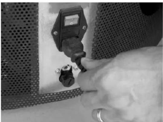
In the period when the stove is out of use it must be disconnected from the electricity mains. For greater safety, especially if there are children around, we recommend removing the power cable from the rear of the stove. (Figure 17)
Before placing the stove in storage, you should remove all pellets from the hopper with a vacuum cleaner with a long extension. If the fuel is
Figure 17 - Disconnect the stove from the electrical mains
left in the hopper, it may get damp, stick together, and be difficult to light at the beginning of the next season. If the stove is removed from its place of installation, MUST be placed in a location that is protected from atmospheric agents. If pressing the main switch (located on the back of the stove) does not make the control panel display light up, it could mean that the service fuse needs replacing.

ATTENTION!
Disconnect the electrical cable.
On the rear of the stove there is a fuse holding compartment which is located underneath the supply socket. With a screwdriver open the cover of the fuse holding compartment, and replace the fuse if necessary (3.15 AT delayed type). Figure 18 Plug the unit back in and press the main switch. If the problem persists or occurs again, contact your MCZ retailer.
5.3. CHECK OF INTERNAL COMPONENTS

ATTENTION!
The check of the internal electromechanical components must be carried out only by qualified personnel with technical knowledge of electricity and combustion. If necessary, contact authorized HANKS retailers.
We recommend that an annual maintenance service is carried out, preferably under a programmed service contract. The essential part of this service is a visual and functional check on the following components:
- Reduction motor
- Smoke expulsion fan
- Smoke sensor
- Heat-exchanger fan
- Ignition sparkplug
- Resettable pellet thermostat
• Room temperature sensor - Motherboard / service card
- Fuses protecting panel - motherboard - services card
- Wiring
The following is a summary of the checks and/or maintenance tasks which are indispensable for the correct operation of the stove.
PELLET BURNING STOVES
INSTALLATION AND MAINTENANCE MANUAL
| Parts / interval | Every day | Every 2-3 days | Every 60-90 days | Every 1 year |
| Grate | ● | |||
| Ash drawer | ● | |||
| Glass | ● | |||
| Lower compartment | ● | |||
| Complete exchanger | ● | |||
| Smoke duct | ● | |||
| Ash drawer door gasket | ● | |||
| Internal parts | ● | |||
| Flue pipe | ● | |||
| Circulation pump | ● | |||
| Plate heat exchanger | ● | |||
| Plumbing components | ● | |||
| Electro-mechanical components | ● |
6. PROBLEMS / CAUSES / SOLUTIONS
NOTE: All repairs must be performed by a technician with the stove off and disconnected the mains.
The control panel of the stove has trouble examine sensors. When the sensor detect the abnormal work temperature (below
40^) , or the other sensor's temperature is above 70^ the auto-control temperature switches will react accordingly. When
temperature is below 30^ C, the safety control system will stop the stove automatically; when the other sensor, fixed into the
hopper, detect the temperature is above 70^ C, the stove will be shut down.
The general troubles, the possible reasons and the solutions are as following, after solving problems, start the stove again:
| problems reason solution | |||
| 1. The start light does not light when power is on | No power in stove or in the control panel. | Check the power and wires. | |
| 2. The blower doesn't work after pressing the start bottom. (option with boiler) | It is normal.It will start automatically when the temperature is above 30 degrees on the venting pipe. | Please wait | |
| No power in stove or in the control panel.Or Unplugged on the mother boardThe low temperature sensor is broken | Check the power and wires.Plug itReplace it | ||
| 3. No feeding after 20 seconds of starting.There are three stages for the feeding process.One is during the several minutes, feeding is constantly. "Feeding" is showing on the LCD displayTwo is the following couple minutes, the feeding light is off.."Lightling" showing on the DisplayThe last stage is that feeding Every several seconds all the time after previous stages. | |||
| A. For the first stage (during first several minutes) | Feed unit is blocked. Check | the auger is blocked or not. | |
| There is the problem about | Check the fasten screw between auger and motor loose or not. | ||
PELLET BURNING STOVES
INSTALLATION AND MAINTENANCE MANUAL
| the connection between motor and auger | Or the auger might jump out | |
| No fuel in the hopper. Fill | the fuel into the hopper. | |
| B. For the second stage It | is normal Please be patient | |
| C. Regarding to the last stage | Feed unit is blocked. Check | the auger is blocked or not. |
| There is the problem about the connection between motor and auger | Check the fasten screw between auger and motor loose or not.Or the auger might jump out | |
| No fuel in the hopper. Fill | the fuel into the hopper. | |
| 4. Feeding not properlyA. too much wood pellet and cannot burned in time | The level of feeding speed too high | Adjust the combustion fan's speed upis |
| B. The fire is off due to little wood pellet can be burned | The level of feeding speed too low | Adjust the combustion fan's speed Down |
| 5 After ignition the power off 15min later. | Pellet feeder unit is off or pellet is too little.30°C temperature switch breaks or the connection wires of switch loose.Not enough pressure in the stove | Check the pellet feeder unit and restart.Check the connection wires or change the 30°C temperature swAdjust the combustion fan's speed up |
| 6 orange and lazy fire, piled pellet, carbon on the glass | Lack of air intake for burning. | Clean the block in gate bar.Check the door and window glass gasket sealed or not.Check the air intake pipe and venting pipe blocked or not, and it. Change to the big diameter pipes if pipes are too long to a combustion.Adjust the combustion fan's speed upCall the dealer to reset the program |
PELLET BURNING STOVES
INSTALLATION AND MAINTENANCE MANUAL
| 7 The fire put out and power is off automatically. | The hopper is empty.No fuel feed.The fuel feed is too little.low temperature switch (30°C) is wrong.Set temperature is reached | Put fuel into the hopper. refer to (2)Lower the speed of combustion fanCool the stove at least 1 hour then operate again or change the low temperature switch (30°C)."ECO" its normal, waiting, after the temperature is blow set on, it will automatically switch on again |
| 8 The blower still works after the stove is cool and fuel feed stops. | The low temperature switch (30°C) is broken. | Change this switch. |
| 9 no enough heat wind Unqualified fuelBlower speed is too high.Heat exchange tubes are dirty. | Use the standard specially pellet.Use higher powerClean the heat exchange tubes. | |
| 10. Showing "Pressure Erro" on the display | Vent pipe is blockedThe door is openingThe are some leakages | Shut down the stove, check the venting pipeClose the door and unplugged then restartCheck it and repair it.Adjust the combustion fan's speed up to offer more pressure in the stove |
| NO increase in temperature with stove in operation | 1. Incorrect combustion adjustment.2. boiler/system dirty3. Insufficient stove power.4.poor pellet quality | 1.check recipe and parameters.2. check and clean the boiler3.Check that stove is properly sized for the requirements of the system.4. Use Hanks pellets. |
| Condensation in boiler 1. Incorrect temperature setting.2.Insufficient fuel consumption. | 1. set the stove to a higher temperature.2.check the recipe and/or technical parameters | |
PELLET BURNING STOVES
INSTALLATION AND MAINTENANCE MANUAL
| Radiators cold in winter 1. | room thermostat (local or remote) set too low if remote thermostat, check if it is defective.2. circulator does not run because blocked.3. Circulator does not run.4.radiator have air in them | 1.set to higher temperature or replace.( if remote)2. free up the circulator by removing the plug and turning the with screwdriver.3. check the electrical connections of the circulator; replace if necessary4.Vent the radiators |
| Hot water is not provided | 1. circulator (pump) blocked | 1. free the circulator (pump) |
Your stove can be powered with a gas driven electrical generator.
However, the generator's electrical regulator may not be compatible with the stove's electronics. The higher the quality of
the generator, the greater the chance that it is compatible with the stove.
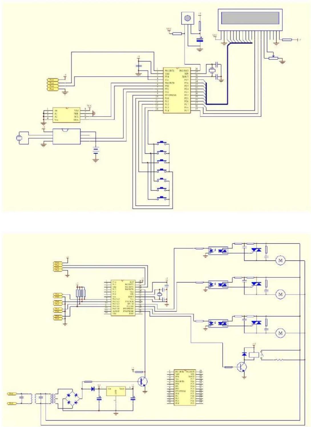
7.electrical diagram