
DS-7204HQI-K1/P - Dictaphone Hikvision - Free user manual and instructions
Find the device manual for free DS-7204HQI-K1/P Hikvision in PDF.


User questions about DS-7204HQI-K1/P Hikvision
0 question about this device. Answer the ones you know or ask your own.
Ask a new question about this device
Download the instructions for your Dictaphone in PDF format for free! Find your manual DS-7204HQI-K1/P - Hikvision and take your electronic device back in hand. On this page are published all the documents necessary for the use of your device. DS-7204HQI-K1/P by Hikvision.
USER MANUAL DS-7204HQI-K1/P Hikvision
natural_image
Abstract geometric composition with gray and red diamond shapes (no text or symbols)
natural_image
Red background with white globe and hand symbol (no text or numbers)DS-72xxHUI-Kx, DS-72xxH“I-Kx
Digital -ideo Recorder (D-R)
...ser Manual
COP√RIGHT © 2017 Hangzhou Hikvision Digital Technology Co., •td.
√LL "IGHTS "ESE"VED.
Any and all information, including, among others, wordings, pictures, graphs are the properties of Hangzhou Hikvision Digital Technology Co., •td. or its subsidiaries (hereinafter referred to be “Hikvision”). This user manual (hereinafter referred to be “the Manual”) cannot be reproduced, changed, translated, or distributed, partially or wholly, by any means, without the prior written permission of Hikvision. ...nless otherwise stipulated, Hikvision does not make any warranties, guarantees or representations, express or implied, regarding to the Manual.
√bout this Manual
This Manual is applicable to -K ^TM eries TurboHD Digital Video Recorders (DVRs).
The Manual includes instructions for using and managing the product. Pictures, charts, images and all other information hereinafter are for description and explanation only. The information contained in the Manual is subject to change, without notice, due to firmware updates or other reasons. Please find the latest version in the company website (http://overseas.hikvision.com/en/).
Images in this manual are for illustrative purposes only and may differ from the actual product.
Please use this user manual under the guidance of professionals.
Trademarks √cknowledgement
HIKVISION and other Hikvision trademarks and logos are the properties of Hikvision in various jurisdictions. Other trademarks and logos mentioned below are the properties of their respective owners.
Legal Disclaimer
TO THE MAXIM...M EXTENT PERMITTED B√APP•ICAB•E•AW, THE PROD...CT DE™CRIBED, WITH IT™ HARDWARE, ™OFTWARE AND FIRMWARE, ™TPROVIDED “A™ I™”, WITH A•• FA...•T™ AND ERROR™, AND HIKVI™ION MAKE™ NO WARRANTY™, EXPRE™TM OR IMP•IED, INC•...DING WITHO...T •IMITATION, MERCHANTABI•IT√, ™ATI™FACTOR√ ≤...A•IT√, FITNE™TM FOR A PARTIC...•AR P...RPO™E, AND NON-INFRINGEMENT OF THIRD PART√. IN NO EVENT WI•• HIKVI™ION, IT™ DIRECTOR™, OFFICER™, EMP•O√EE™, OR AGENT™ BE •IAB•E TO √O... FOR AN√™PECIA•, CON™E ≤...ENTIA•, INCIDENTA•, OR INDIRECT DAMAGE™, INC•...DING, AMONG OTHER™, DAMAGE™ FOR •O™TM OF B...™INET™ PROFIT™, B...™INET™ INTERR...PTION, OR •O™TM OF DATA OR DOC...MENTATION, IN CONNECTION WITH THE ...™E OF THI™ PROD...CT, EVEN IF HIKVI™ION HA™ BEEN ADVIT™ED OF THE PO™TMIBI•IT√OF ™...CH DAMAGE™.
REGARDING TO THE PROD...CT WITH INTERNET ACCE™TM, THE ...™E OF PROD...CT ™HA●● BE WHO●●√ AT √O...R OWN RI™K™. HIKVI™ION ™HA●● NOT TAKE AN√ RE™PON™IBI●ITE™ FOR ABNORMA● OPERATION, PRIVAC√●EAKAGE OR OTHER DAMAGE™ RE™ ...●TING FROM C√BER ATTACK, HACKER ATTACK, VIR...™ IN™PECTION, OR OTHER INTERNET ™EC...RIT√ RI™K™; HOWEVER, HIKVI™ION WI●● PROVIDE TIME●√ TECHNICA●™...PPORT IF RE ≤...IRED.
TM...RVEI•ANCE •AW™ VAR√B√J...RI™DICTION. P•EATM E CHECK A•• RE•EVANT •AW™ IN √O...R J...RI™DICTION BEFORE ...™ING THITM PROD...CT IN ORDER TO EN™...RE THAT √O...R ...™E CONFORM™ THE APP•ICAB•E •AW. HIKVITMION™HA•• NOT BE •IAB•E IN THE EVENT THAT THITM PROD...CT ITM ...™ED WITH I••EGITIMATE P...RPO™ETM.
IN THE EVENT OF AN√CONF•ICT™ BETWEEN THI™ MAN...A• AND THE APP•ICAB•E •AW, THE •ATER PREVAI•™.
"egulatory Information
FCC Information
Please take attention that changes or modification not expressly approved by the party responsible for compliance could void the user's authority to operate the equipment.
FCC Compliance: This equipment has been tested and found to comply with the limits for a Class A digital device, pursuant to part 15 of the FCC Rules. These limits are designed to provide reasonable protection against harmful interference when the equipment is operated in a commercial environment. This equipment generates, uses, and can radiate radio frequency energy and, if not installed and used in accordance with the instruction manual, may cause harmful interference to radio communications. Operation of this equipment in a residential area is likely to cause harmful interference in which case the user will be required to correct the interference at his/her own expense.
FCC Conditions
This device complies with part 15 of the FCC Rules. Operation is subject to the following two conditions"
- This device may not cause harmful interference.
- This device must accept any interference received, including interference that may cause undesired operation.
EU Conformity Statement

This product and - if applicable - the supplied accessories too are marked with "CE" and comply therefore with the applicable harmonized European standards listed under the EMC Directive 2014/30/E..., the •VD Directive 2014/35/E..., the RoH™ Directive 2011/65/E...

2012/1"/E... (WEEE directive)" Products marked with this symbol cannot be disposed of as unsorted municipal waste in the European ...nion. For proper recycling, return this product to your local supplier upon the purchase of equivalent new equipment, or dispose of it at designated collection points. For more
information see" www.recyclethis.info

2006/66/EC (battery directive)" This product contains a battery that cannot be disposed of as unsorted municipal waste in the European ...nion. ™ee the product documentation for specific battery information. The battery is marked with this symbol, which may include lettering to indicate cadmium (Cd), lead (Pb), or mercury (Hg). For proper recycling, return the battery to your supplier or to a designated collection point. For
more information see" www.recyclethis.info
Industry Canada ICES-003 Compliance
This device meets the CAN ICE ^TM -3 (A)/NMB-3(A) standards requirements.
Applicable Models
This manual is applicable to the models listed in the following table.
| ^TM eries Model | |
| D^TM-72xxH ≤ I-Kx | D^TM-7204H ≤ I-K1 D^TM-7208H ≤ I-K2 D^TM-7216H ≤ I-K2 |
| D^TM-72xxH...I-Kx | D^TM-7204H...I-K1 D^TM-7208H...I-K2 D^TM-7216H...I-K2 |
^TM ymbol 'onventions
The symbols in this document are defined as follows.
| ^TM Symbol Description | |
 NOTE NOTE | Provides additional information to emphasize or supplement important points of the main text. |
 WARNING WARNING | Indicates a potentially hazardous situation, which if not avoided, could result in equipment damage, data loss, performance degradation, or unexpected results. |
 DANGER DANGER | Indicates a hazard with a high level of risk, which if not avoided, will result in death or serious injury. |
^TM safety Instructions
- Proper configuration of all passwords and other security settings is the responsibility of the installer and/or end-user.
- In the use of the product, you must be in strict compliance with the electrical safety regulations of the nation and region. Please refer to technical specifications for detailed information.
- Input voltage should meet both the ™E•—(™afety Extra •ow -oltage) and the •imited Power ™ource with 100 to 240 –A' or 12 –D' according to the IE'60"50-1 standard. Please refer to technical specifications for detailed information.
- Do not connect several devices to one power adapter as adapter overload may cause over-heating or a fire hazard.
- Please make sure that the plug is firmly connected to the power socket.
- If smoke, odor or noise rise from the device, turn off the power at once and unplug the power cable, and then please contact the service center.
Preventive and 'autionary Tips
Before connecting and operating your device, please be advised of the following tips"
- Ensure unit is installed in a well-ventilated, dust-free environment.
- ...nit is designed for indoor use only.
- Keep all liquids away from the device.
- Ensure environmental conditions meet factory specifications.
- Ensure unit is properly secured to a rack or shelf. Major shocks or jolts to the unit as a result of dropping it may cause damage to the sensitive electronics within the unit.
- ...se the device in conjunction with an ... P^TM if possible.
• Power down the unit before connecting and disconnecting accessories and peripherals. - A factory recommended HDD should be used for this device.
- Improper use or replacement of the battery may result in hazard of explosion. Replace with the same or equivalent type only. Dispose of used batteries according to the instructions provided by the battery manufacturer.
- Ensure to use the attached power adaptor only and not to change the adaptor randomly.
-roduct Key Features
General
- Connectable to Turbo HD and analog cameras
- ^TM supports ...TC protocol for connecting camera over coax
- Connectable to IP cameras
- The analog signal inputs including TurboHD and CVB™ can be automatically recognized without configuration
• Each channel supports dual-stream, and sub-stream supports up to WD1 resolution
• The main stream of D™-72xxH ≤ I-Kx ™eries supports up to 3 MP resolution for the first 4 channels - The main stream of D ^TM -72xxH...I-Kx ^TM eries supports up to 5 MP resolution of all the channels
- For D™-72xxH...I-Kx ™eries DVR, 5 MP long distance transmission can be enabled for the analog cameras
• Independent configuration for each channel, including resolution, frame rate, bit rate, image quality, etc. - Encoding for both video stream and video & audio stream; audio and video synchronization during composite stream encoding
- ^TM supports enabling H.265+/H.264+ to ensure high video quality with lowered bit rate
- H.265+/H.265/H.264+/H.264 encoding for the main stream, and H.265/H.264 encoding for the sub-stream of analog cameras
- Connectable to H.265 and H.264 IP cameras
- Defog level, night to day sensitivity, day to night sensitivity, and IR light brightness configurable for the connected analog cameras supporting these parameters
- 4 MP/5 MP signal switch for the supported analog cameras
• Watermark technology
Local Monitoring
• HDMI output at up to 4K (3840 × 2160) resolution
• 1/4/6/8/9/16/25 screen live view is supported, and the display sequence of screens is adjustable
- Live view screen can be switched in group and manual switch and automatic cycle live view are also provided, the interval of automatic cycle can be adjusted
- CVB™ output only serves as the aux output or live view output
- ≤ quick setting menu is provided for live view
- The selected live view channel can be shielded
- VCA information overlay in live view for the supported analog cameras and in smart playback for the supported analog and IP cameras
• Motion detection, video-tampering detection, video exception alarm, video loss alarm and VCA alarm functions
- D™-72xxH...I-Kx ™eries DVRs support VCA (line crossing detection and intrusion detection) of all channels. D™-7216H≤I-Kx ™eries DVRs support 2-ch VCA (line crossing detection and intrusion detection). For the analog channels, the line crossing detection and intrusion detection conflict with other VCA detection such as sudden scene change detection, face detection and vehicle detection. √ou can enable only one function.
- For DS-72xxHUI-Kx Series DVRs, the enhanced VCA mode conflicts with the 2K/4K output and 4 MP/5 MP signal input
- Privacy mask
• Several PTZ protocols (including Omnicast VMS of Genetec) supported; PTZ preset, patrol and pattern - Zooming in/out by clicking the mouse and PTZ tracing by dragging mouse
HDD Management
• Each disk with a maximum of 8 TB storage capacity
- 8 network disks (8 NAS disks, 8 IP SAN disks or n NA S disks + m IP SAN disks (n + m ≤ 8) ) can be connected
- Remaining recording time of the HDD can be viewed
• S.M.A.R.T. and bad sector detection
- HDD sleeping function
• HDD property: redundancy, read-only, read/write (R/W)
- HDD group management
- HDD quota management; different capacity can be assigned to different channels
"ecording and -layback
• Holiday recording schedule configuration
• Cycle and non-cycle recording modes
• Normal and event video encoding parameters
- Multiple recording types: manual, continuous, alarm, motion, motion | alarm, motion & alarm and event
- Eight recording time periods with separated recording types
• Supports Channel-Zero encoding
- Main stream and sub-stream configurable for simultaneous recording
- Pre-record and post-record for motion detection triggered recording, and pre-record time for schedule and manual recording
- Searching record files by events (alarm input/motion detection)
- Customization of tags, searching and playing back by tags
- Locking and unlocking of record files
- Local redundant recording
- When TurboHD input is connected, the information including the resolution and frame rate will be overlaid on the bottom right corner of the live view for 5 seconds. When CVBS input is connected, the information such as NTSC or PAL will be overlaid on the bottom right corner of the live view for 5 seconds.
• Searching and playing back record files by camera number, recording type, start time, end time, etc.
- Smart playback to go through less effective information
- Main stream and sub-stream selectable for local/remote playback
-
Zooming in for any area when playback
• Multi-channel reverse playback -
™upports pause, fast forward, slow forward, skip forward, and skip backward when playback, locating by dragging the mouse on the progress bar
• 8/16-ch synchronous playback
Backup
- Exports data to a ... ^TM B device
- Exports video clips for playback
• Video and Log, Video and Player, and Player are sele ctable to export for backup - Management and maintenance of backup devices
√larm and Exception
- Configurable arming time of alarm input/output
- Alarms for video loss, motion detection, video tampering, abnormal signal, video input/recording resolution mismatch, illegal login, network disconnected, IP confliction, record/capture exception, HDD error, HDD full, etc.
• Alarm triggers full screen monitoring, audio alarm, notifying surveillance center, sending e-mail, and alarm output - One-key disarms the linkage actions of the alarm input
• PTZ linking for the VCA alarm
• VCA detection alarm is supported - TM supports coaxial alarm
- ^TM ystem will automatically reboot when a problem is detected in an attempt to restore normal functionality
'ther Local Functions
- Manual and automatic video quality diagnostics
- Operable by mouse and remote control
- Three-level user management; admin user can create many operating account and define their operating permission, which includes the permission to access any channel
- Completeness of operation, alarm, exceptions and log writing and searching
- Manually triggering and clearing alarms
- Importing and exporting of configuration file of devices
• Getting cameras type information automatically - ...nlock pattern for device login for the admin
- Clear-text password available
• G...ID file can be exported for password resetting - Multiple connected TurboHD signal analog cameras can be upgraded simultaneously via DVR
^TM network Functions
• 1 self-adaptive 10M/100M/1000M network interface
- IPv6 is supported
- TCP/IP protocol, PPPoE, DHCP, DNS, DDNS, NTP, SADP, SMTP, NFS, iSCSI, UPnP™, and HTTPS are supported
- Supports access by Hik-Connect. If you enable Hik-Connect, the device will remind you of Internet access risk and ask you to confirm the “Terms of Service” and “Privacy Statement” before enabling the service. √ou should create a verification code to connect to Hik-Connect.
• TCP, UDP, and RTP for unicast
• Auto/Manual port mapping by UPnP™
- Remote search, playback, download, locking and unlocking record files, and downloading files broken transfer resume
- Remote parameters setup; remote import/export of device parameters
- Remote viewing of device status, system logs, and alarm status
- Remote keyboard operation
- Remote HDD formatting and program upgrading
- Remote system restart and shutdown
• Supports upgrading via remote FTP server
• RS-485 transparent channel transmission
- Alarm and exception information can be sent to the remote host
- Remotely start/stop recording
- Remotely start/stop alarm output
- Remote PTZ control
- Two-way audio and voice broadcasting
• Output bandwidth limit configurable
- Embedded WEB server
- If DHCP is enabled, ability to enable DNS DHCP or disable it and edit the Preferred DNS Server and Alternate DNS Server
Development Scalability
- SDK for Windows and Linux system
- Source code of application software for demo
• Development support and training for application system
Table of Contents
Chapter • Introduction •4
1.1 Front Panel 14
1.2 IR Remote 'ontrol Operations.... 14
1.2.1 ...sing the Remote 'ontrol.... 15
1.2.2 Troubleshooting Remote 'ontrol 16
1.3 ...TMB Mouse.... 16
1.3.1 Mouse Operation....17
1.3.2 Input Method.... 17
1.3.3 Description of theTMoft Keyboard Buttons 17
1.4 Rear Panel.... 18
Chapter 2 Getting Started 20
2.1 ™tarting ...p and ™hutting Down the D–R 20
2.1.1 BeforeTMtarting....20
2.1.2 ™tarting the D-R....20
2.1.3 ™hutting Down the D-R 20
2.1.4 Rebooting the D-R....21
2.2 Activating the Device 21
2.3 ...sing the ...nlock Pattern for •ogin 22
2.3.1 'onfiguring the ...nlock Pattern....23
2.3.2 •ogging in via ...nlock Pattern 24
2.4 •ogin and •ogout 25
2.4.1 ...ser •ogin 25
2.4.2 ...ser •ogout 26
2.5 Resetting √our Password 27
2.6 Adding and 'onnecting IP 'ameras.... 28
2.6.1 Activating IP 'ameras 28
2.6.2 Adding an Online IP 'amera 32
2.6.3 Editing the 'onnected IP 'amera 34
Chapter 3 Live View 36
3.1 Introduction....36
3.1.1 •ive -iew Icons.... 36
3.2 Operations in •ive -iew Mode 36
3.2.1 ...sing the Mouse in •ive -iew.... 37
3.2.2 ™witching Main/Aux Output 38
3.2.3 ≤ uick ™etting Toolbar in •ive -iew Mode 38
3.3 'hannel-Zero Encoding....42
3.3 'hannel-Zero Encoding....42
3.4 Adjusting •ive -iew ™ettings.... 42
3.5 Manual -ideo ≤ uality Diagnostics 44
3.4 Adjusting •ive –iew™ettings.... 42 3.5 Manual –ideo ≤ uality Diagnostics.... 44
Chapter 4 -TZ Controls 46
4.1 'onfiguring PTZ™ettings.... 46
4.2 ™etting PTZ Presets, Patrols, and Patterns 48
4.2.1 'ustomizing Presets....48
4.2.2 'alling Presets.... 4"
4.2.3 'ustomizing Patrols....50
4.2.4 'alling Patrols....52
4.2.5 'ustomizing Patterns.... 52
4.2.6 'alling Patterns 53
4.2.7 'ustomizing •inear ™ can •imit 54
4.2.8 'alling •inear™ can....55
4.2.“ One-Touch Park 56
4.3 PTZ 'ontrol Panel 57
Chapter 5 "ecording Settings 59
5.1 'onfiguring Encoding Parameters 5"
5.1.1 Before™tarting.... 5"
5.1.2 'onfigure Record Parameters 5"
5.2 'onfiguring Recording ™schedule 64
5.2.1 ™et the Record ™schedule 64
5.2.2 Edit the ™schedule....65
5.2.3 Draw the schedule 66
5.3 'onfiguring Motion Detection Recording 67
5.4 'onfiguring Alarm Triggered Recording and 'apture....68
5.5 'onfiguring Event Recording....70
5.6 'onfiguring Manual Recording 72
5.7 'onfiguring Holiday Recording 73
5.8 'onfiguring Redundant Recording....74
5." 'onfiguring HDD Group....76
5.10 Files Protection....77
5.10.1 Protect File by •ocking the Record Files....77
5.10.2 Protect File by ™etting HDD Property to Read-Only 78
5.11 One-Key Enabling and Disabling H.264+/H.265+ for Analog 'ameras 7"
5.11.1 One-Key Enabling H.264+/H.265+ All Analog 'ameras....7"
5.11.2 One-Key Disabling H.264+/H.265+ All Analog 'ameras 80
5.12 'onfiguring 1080p •ite....80
5.12.1 Enabling 1080p •ite Mode 81
5.12.2 Disabling the 1080p •ite Mode ....81
Chapter 6 -layback 82
6.1 Playing Back Record Files 82
6.1.1 Instant Playback 82
6.1.1.1 Instant Playback by 'hannel 82
6.1.1.2 Playing Back by Normal ™earch 82
6.2 Playback Auxiliary Functions ....“7
6.2.1 Playing Back Frame-by-Frame ..... "7
6.2.2 Digital Zoom......“8
6.2.3 Reverse Playback of Multi-'hannel....."8
Chapter 7 Backup •00
7.1 Backing up Record Files.... 100
7.1.1 Backing ...p by Normal -ideo/Picture ™earch.... 100
7.1.2 Backing ...p -ideo 'lips 103
7.2 Managing Backup Devices 103
7.2.1 Management of ...TMB Flash Drives, and ...TMB HDDs 103
Chapter 8 √larm Settings •05
8.1 ™etting Motion Detection.... 105
8.2 ™etting ™ensor Alarms 107
8.3 Detecting –ideo •oss.... 10"
8.4 Detecting –ideo Tampering .... 111
8.5 ™etting All-day –ideo ≤ uality Diagnostics 113
8.6 Handling Exceptions 115
8.7 ™etting Alarm Response Actions 117
Chapter 9 VC√√larm •20
“.1 Face Detection.... 120
".2 •ine 'rossing Detection....122
“.3 Intrusion Detection.... 123
“.4 Region Entrance Detection....126
".5 Region Exiting Detection....127
“.6 •oitering Detection....127
".7 People Gathering Detection.... 128
".8 Fast Moving Detection....128
“ Parking Detection 128
".10 ...nattended Baggage Detection.... 128
".11 Object Removal Detection.... 12"
".12 Audio Exception Detection.... 12"
".13 Defocus Detection 130
".14 ™mudden ™cene 'hange.... 130
".15 PIR Alarm 131
Chapter •0 VC√ Search
10.1 Face ™search 132
10.2 Behavior™earch 134
10.3 People 'ounting 135
10.4 Heat Map....136
Chapter •• ™Network Settings
11.1 'onfiguring General™ettings.... 138
11.2 'onfiguring Advanced™ettings.... 13"
11.2.1 'onfiguring PPPoE™ettings.... 13"
11.2.2 'onfiguring Hik-'onnect.... 13"
11.2.3 'onfiguring DDN™ 141
11.2.4 'onfiguring NTP ^TM erver....143
11.2.5 'onfiguring NAT 144
11.2.6 'onfiguring More™ettings 146
11.2.7 'onfiguring HTTP™ Port 147
11.2.8 'onfiguring E-Mail 14"
11.2.8.1 Before ™tarting 14"
11.2.8.2 Procedure 14"
11.2." 'hecking Network Traffic.... 151
11.3 'onfiguring Network Detection 151
11.3.1 Testing Network Delay and Packet •oss 151
11.3.2 Exporting Network Packet 152
11.3.3 'hecking Network ™tatus.... 153
11.3.4 'hecking Network ™tatistics 154
Chapter •2 HDD Management •55
12.1 Initializing HDDs 155
12.2 Managing Network HDD 156
12.3 Managing HDD Groups.... 158
12.3.1 ™etting HDD Groups 158
12.3.2 ™etting HDD Property 160
12.4 'onfiguring ≤ uota Mode.... 161
12.5 'onfiguring 'loud ™torage.... 162
12.6 'hecking HDD ™tatus.... 165
12.7 'hecking ™.M.A.R.T. Information 166
12.8 Detecting Bad ™ectors 166
12." 'onfiguring HDD Error Alarms.... 167
Chapter •3 Camera Settings •69
13.1 Assigning 5 MP •ong Distance Transmission.... 16"
13.2 'onfiguring O™D ™ettings.... 170
13.3 'onfiguring Privacy Mask.... 171
13.4 'onfiguring –ideo Parameters.... 172
13.4.1 'onfiguring Image™ettings.... 172
13.4.2 'onfiguring 'amera Parameters ™ettings 174
Chapter •4 DV" Management and Maintenance •76
14.1 -iewingTMystem Information 176
14.2 ™searching •og Files 176
14.3 Importing/Exporting IP 'amera Info.... 178
14.4 Importing/Exporting 'onfiguration Files 178
14.5 ...pgrading ™ystem 17"
14.5.1 ...pgrading by •ocal Backup Device 17"
14.5.2 ...pgrading by FTP 180
14.6 ...pgrading 'amera 181
14.7 Restoring Default™ettings 182
Chapter •5 'thers •84
D^TM-72xxH...I-Kx, D^TM-72xxH ≤ I-Kx Digital -ideo Recorder (D-R) ...ser Manual
15.1 'onfiguring General™ettings.... 184
15.2 'onfiguring D™T™ettings 184
15.3 'onfiguring More™ettings 186
15.4 Managing ...ser Accounts.... 188
15.4.1 Adding a ...ser.... 188
15.4.2 Deleting a ...ser.... 1"2
15.4.3 Editing a ...ser 1"2
Chapter •6 √ppendix •95
16.1 Glossary.... 1"5
16.2 Troubleshooting.... 1"6
Chapter • Introduction
•• Front -anel
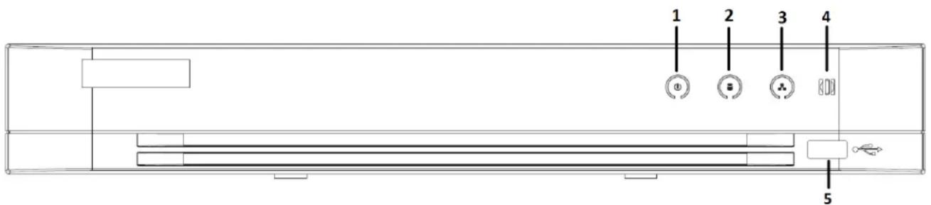
text_image
1 2 3 4 5Figure 1, Front Panel of D ^TM -7216H ≤ I-Kx and D ^TM -72xxH...I-Kx
Table 1-1 Front Panel Description
| ^TMO | Icon | Description |
| 1 | [ WyHD] | •ights when D–R is powered up |
| 2 |  | •ights when data is being read from or written to HDD |
| 3 | [YSXT] | Flashes when the network is well connected |
| 4 |  | IR remote control receiver |
| 5 USB Interface | ...niversal ^TM erial Bus ( ^TMB ) portsr additional devices such as ^TMB moue and ^TMB Hard Disk Drive (HDF | |
•.2 I” ”emote Control 'perations
The D-R may also be controlled with the included IR remote control, shown in Figure 1-“.

2 × AAA batteries must be installed before operation.
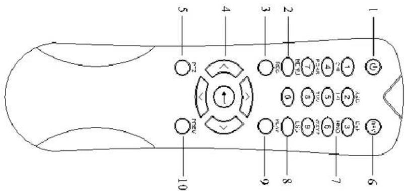
The remote control keys resemble the ones on the front panel (see Table 1-2).
Table 1-2 Description of the IR Remote 'ontrol Buttons
| ^TMO | ^TMame | Description |
| 1 | -‘WE” | Power on/off the device by pressing and holding the button for 5 seconds |
| 2 | MET^TMU Button | Press the button to return to the main menu (after successful login) |
| Press and hold the button for 5 seconds will turn off audible key beep | ||
| In PTZ ’ontro I mode, the MEN... button will start wiper (if applicable | ||
| In Playback mode, it is used to show/hide the control interface | ||
| 3 | “EC Button | Enter the Manual Record setting menu |
| In PTZ control settings, press the button and then you can call a PTZ preset by pressing Numeric button | ||
| It is also used to turn audio on/off in the Playback mode | ||
| 4 | DI”ECTI’ ^TM Button | Navigate between different fields and items in menus |
| In the Playback mode, the ...p and Down button is used to speed up and slow down recorded video. The •eft and Right button will select the next and previous record files . | ||
| In •ive -iew mode, these buttons can be used to cycle through channels | ||
| In PTZ control mode, it can control the movement of the PTZ camera | ||
| E^TMTE ” Button | ’onfirm selection in any of the menu modes | |
| It can also be used to tick checkbox fields | ||
| In Playback mode, it can be used to play or pause the video | ||
| In single-frame Playback mode, pressing the button will advance the video by a single frame | ||
| 5 | -TZ Button | In Auto-switch mode, it can be used to stop /start auto switch |
| 6 | DEV | Enables/Disables Remote ’ontrol |
| 7 | √lphanumeric Buttons | ^TM witch to the corresponding channel in •ive view or PTZ ’ontrol mode |
| Input numbers and characters in Edit mode | ||
| ^TM witch between different channels in the Playback mode | ||
| 8 | ESC Button | Back to the previous menu |
| Press for Arming/disarming the device in •ive -iew mode | ||
| “ | -L√Y Button | The button is used to enter the All-day Playback mode |
| It is also used to auto scan in the PTZ ’ontrol menu | ||
| 10 | -“EV Button | ^TM witch between single screen and mult-screen mode |
| In PTZ ’ontrol mode, it is used to adjust the focus in conjunction with the A/FO’... ^TM + button |
1.2.2 Troubleshooting Remote Control

NOTE
Make sure you have installed batteries properly in the remote control. Also, the remote control must be aimed at the IR receiver on the front panel.
If there is no response after you press a button on the remote, follow the procedure below to troubleshoot.
- Go into Menu > 'onfiguration > General > More ™ettin gs by operating the front control panel or the mouse.
- 'heck and remember the D-R No. The default D-R No. is 255. This number is valid for all IR remote controls.
- Press the DE– button on the remote control.
- Enter the D-R No. in step 2.
- Press the ENTER button on the remote.
If the ™tatus indicator on the front panel turns blue, the remote control is operating properly. If the ™tatus indicator does not turn blue and there is still no response from the remote, check the following"
- Batteries are installed correctly and the polarities of the batteries are not reversed
- Batteries are fresh and not out of charge
• IR receiver is not obstructed
If the remote still does not function properly, change the remote and try again, or contact the device provider.
1.3 USB Mouse
A regular 3-button (•eft/Right™croll-wheel) ...™B mouse can also be used with this D-R.
- Plug ... ^TM B mouse into one of the ... ^TM B interfaces on the front panel of the D-R.
- The mouse should be detected automatically. If the mouse is not detected, the possible reason may be that the two devices are not compatible. Refer to the recommended device list from your provider.
•.3.• Mouse 'peration
Table 1-3 Description of the Mouse Control
| TMame | √ctior | Description |
| Left-Click | Single-Click | Live view: TMelect channel and show the quick set menuMenu: TMlect and enter |
| Double-Click | Live view: TMwitch between single-screen and multi-screen | |
| Drag | PTZ control: WheelingPrivacy mask and motion detection: TMelect target areaDigital zoom-in: Drag and select target areaLive view: Drag channel/time bar | |
| "ight-Click Single-Click | Live view: TMhow menlMenu: Exit current menu to upper level menu | |
| Scroll-Wheel | Scrolling up | Live view: Previous screenMenu: Previous item |
| Scrolling down | Live view: Next screenMenu: Next item | |
•.3.2 Input Method
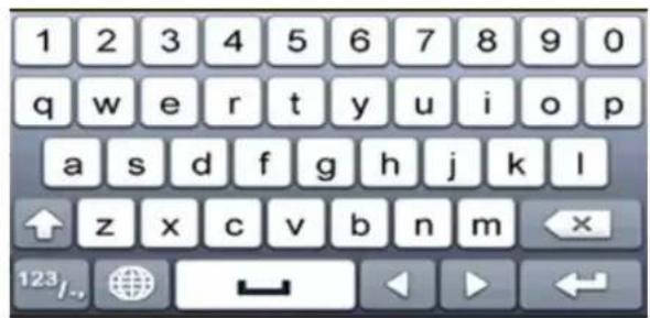
text_image
1 2 3 4 5 6 7 8 9 0 q w e r t y u i o p a s d f g h j k l z x c v b n m 123/..Figure 3, ^TM oft Keyboard
•.3.3 Description of the Soft Keyboard Buttons
Table 1-4 Description of the ™oft Keyboard Icons
| Icon Description Icon Description | |||
| 0...9 | Numbers | A...Z | Letters |
| Lowercase/uppercase | Backspace | ||
| 123/.. ABC | TMwitch the keyboard | TMpace | |
| Position the cursor | Enter | ||
| #+= | TMymbols | Reserved | |
•.4 "ear -anel
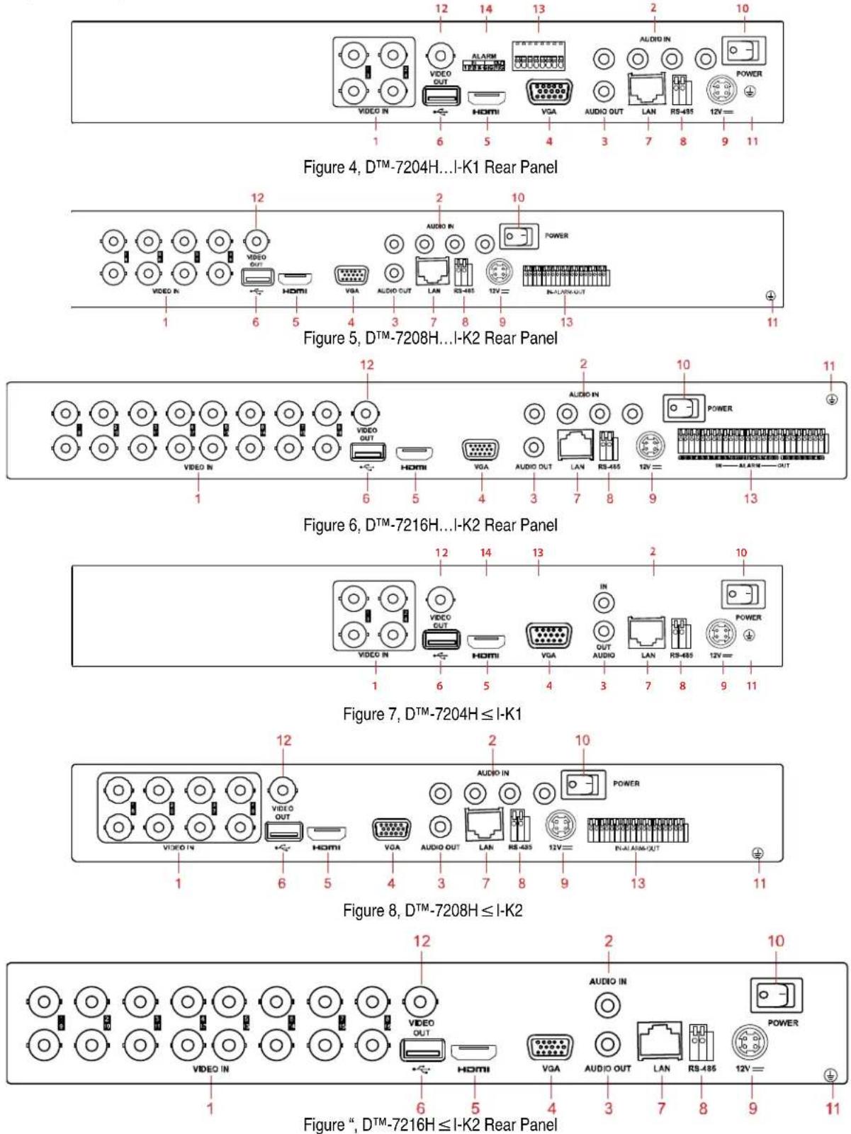
Table 1-5 Description of Rear Panels
| ^TMO | Item | Description |
| 1 | VIDE’ I^TM | BN’ interface for TurboHD and analog video input |
| 2 | ’ I^TM | R’A connector |
| 3 | ’UT | R’A connect or |
| 4 | VG _ | DB-15 connector for –GA output. Display local video output and menu. |
| 5 | HDMI | HDMI video output connector |
| 6 | USB –ort | .. ^TME port for additional devices |
| 7 | ^TMNetwork Interface | ’onnector for network |
| 8 | ”S-485 Interface | ’onnector for R ^TM -485 devices |
| “ | –ower Supply | 12 –D’ power supply |
| 10 | –ower Switch | ^TMwith for turning on/off the device |
| 11 | G ^TM [ | Ground |
| 12 | VIDE’ ’UT | BN’ connector for video output |
| 13 | In/'ut | ’onne ctor for alarm input and output |
Chapter 2 Getting Started
2. Starting Up and Shutting Down the DV"
Proper startup and shutdown procedures are crucial to expanding the life of the DVR.
2. • • Before Starting
Check that the power supply voltage matches the DVR's requirement, and ensure the ground connection is working properly.
2.2 Starting the DV"
- Plug the power cord into an electrical outlet. It is HIGH•√ recommended that an ...interruptible Power ^TM supply (...PTM) be used in conjunction with the device.
- Turn on the power switch on the rear panel, and the Power indicator •ED should turn on indicating that the unit is starting.
- After startup, the Power indicator •ED remains on.
2.3 Shutting Down the DV"
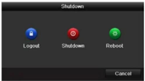
- Enter the ™hutdown menu, Menu > Maintenance > ™hutdown (icon in lower left corner).
text_image
Shutdown Logout Shutdown Reboot CancelFigure 10, ™hutdown Menu
- Click Shutdown.
- Click Yes.
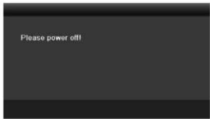
- Turn off the rear panel power switch (16 channel only) when the "Please Power Off" prompt appears.
text_image
Please power off!Figure 11, ^TM shutdown Prompt
2.4 "ebooting the DV"
While in the ™ shutdown menu, you can also reboot the DVR.
- Enter the ™hutdown menu by clicking Menu > ™hutdown.
- 'lick Logout to log out or "eboot to reboot."
2.2 √ctivating the Device
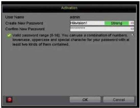
For first-time access, you must activate the device by setting an admin password. No operation is allowed before activation. √ou can also activate the device via Web browser, ™ADP, or client software.
- Input the same password in the 'reate New Password and 'onfirm New Password text fields.

'lick 🔗 to show/hide the password.
text_image
Activation User Name Create New Password Confirm New Password admin Hikvision1 Strong Valid password range [8-16]. You can use a combination of numbers, lowercase, uppercase and special character for your password with at least two kinds of them contained. OK CancelFigure 12, ™ettings Admin Password

WARNING
ST™G –√SSW”D “EC'MME™DED – We highly recommend you create a strong password of your own choosing (using a minimum of eight characters, including at least three of the following categories” upper case letters, lower case letters, numbers, and special characters) in order to increase the security of your product. We also recommend that you reset your password regularly. Resetting the password monthly or weekly can better protect your product.
- 'lick 'K to save the password and activate the device.

NOTE
'lick to show the password. 'lick again to hide the password.
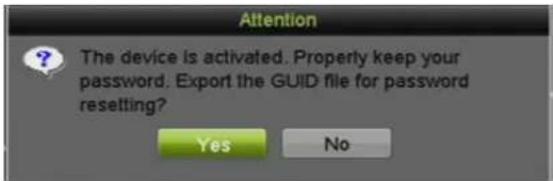
- After the device has been activated, the G...ID Attent ion box pops up as below.
text_image
Attention The device is activated. Properly keep your password. Export the GUID file for password resetting? Yes NoFigure 13, Attention Window
- (Optional) 'lick Yes to export G...ID. The Reset Password window pops up. 'lick Export to export G...ID to the ...TMB flash drive for password resetting.
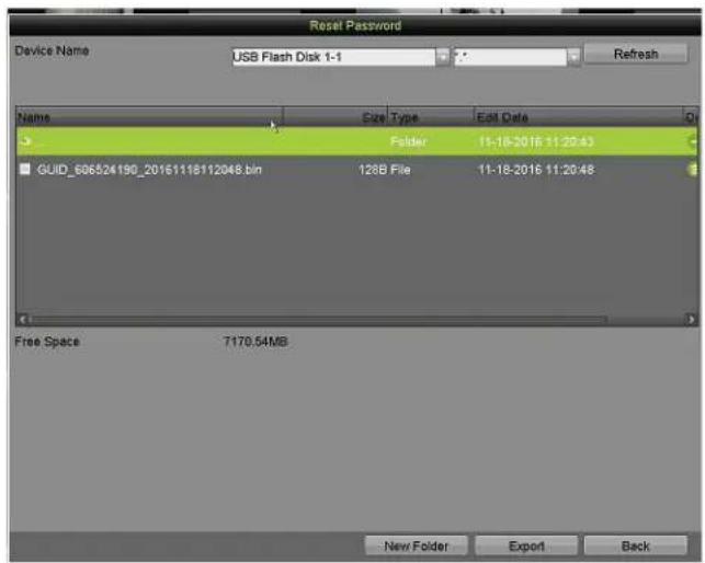
text_image
Reset Password Device Name USB Flash Disk 1-1 Refresh Name Size Type Edit Date Folder 11-18-2016 11:20:43 GUID_606524190_20161118112048.bin 128B File 11-18-2016 11:20:48 Free Space 7170.54MB New Folder Export BackFigure 14, Export G...ID
- After exporting the G...ID, the Attention box pops up as below. 'lick Yes to duplicate the password or TMo to cancel it.
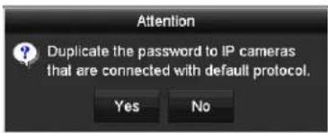
text_image
Attention Duplicate the password to IP cameras that are connected with default protocol. Yes NoFigure 15, Duplicate the Password
2.3 Using the Unlock -attern for Login
For the admin, you can configure the unlock pattern for device login.
2.3. Configuring the Unlock -attern
After the device is activated, enter the following interface to configure the device unlock pattern.

text_image
Set Unlock Pattern Draw the unlock pattern first.Figure 16, ™et ...nlock Pattern
- ...se the mouse to draw a pattern among the nine dots on the screen. Release the mouse when the pattern is done.
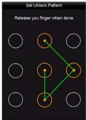
flowchart
graph TD
    A["Start"] --> B{Step 1}
    B --> C["Step 2"]
    C --> D["Step 3"]
    D --> E["End"]
    style A fill:#fff,stroke:#000
    style E fill:#fff,stroke:#000
    style B fill:#fff,stroke:#000
    style C fill:#fff,stroke:#000
    style D fill:#fff,stroke:#000
    style F fill:#fff,stroke:#000
    style G fill:#fff,stroke:#000
    style H fill:#fff,stroke:#000
Figure 17, Draw the Pattern
i NOTE
'onnect at least four dots to draw the pattern.
Each dot can connect only once.
- Draw the same pattern again to confirm it. When the two patterns match, the pattern is successfully configured.
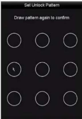
text_image
Set Unlock Pattern Draw pattern again to confirm.Figure 18, 'onfirm the Pattern
i NOTE
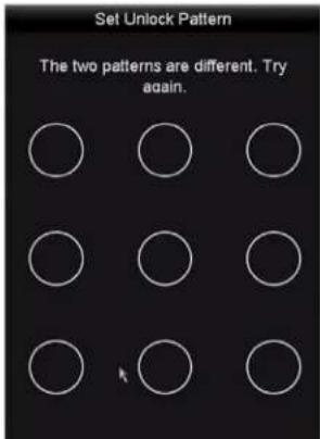
If the two patterns are different, you must set the pattern again.
text_image
Set Unlock Pattern The two patterns are different. Try again.Figure 1", Reset the Pattern
2.3.2 Logging in via Unlock -attern
i NOTE
Only the adminuser has permission to unlock the device.
'onfigure the pattern before unlocking. Refer to section 2.3.1 'onfiguring the ...nlock Pattern.
- Right click the mouse on the screen and select the menu to enter the interface.

text_image
Unlock admin Draw the unlock pattern first. Forget My P... Switch UserFigure 20, Draw the ...nlock Pattern
- Draw the pre-defined unlock pattern to enter the menu.
i NOTE
Right click the mouse to log in via the normal mode.
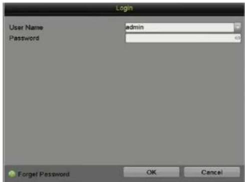
If you have forgotten your pattern, select Forgot My -attern or Switch User to show the normal login dialog box.
If the pattern you draw is different from the pattern you configured, try again. If you draw the wrong pattern seven times, the account will lock for one minute.
text_image
Login User Name admin Password Forget Password OK CancelFigure 21, Normal •ogin Dialog Box
2.4 Login and Logout
2.4. User Login
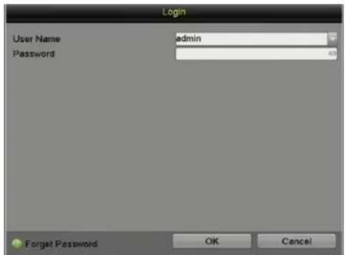
√ou must log in to the device before operating the menu and other functions
- ™elect the User ™ame in the drop-down list.
text_image
Login User Name admin Password Forget Password OK CancelFigure 22, •ogin Interface
-
Enter the -assword.
-
'lick 'K to log in.
i NOTE
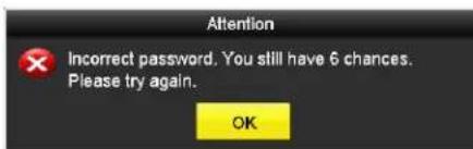
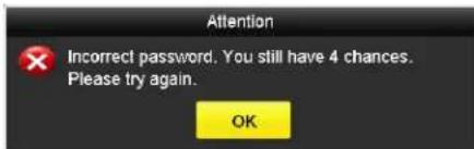
If the admin enters the wrong logon password seven times, the account will lock for 60 seconds. If an operator enters the wrong password five times, the account will lock for 60 seconds.
text_image
Attention Incorrect password. You still have 6 chances. Please try again. OKFigure 23, ...ser Account Protection for the Admin
text_image
Attention Incorrect password. You still have 4 chances. Please try again. OKFigure 24, ...ser Account Protection for the Operator
2.4.2 User Logout
After logging out, the monitor changes to •ive -iew mode. To perform operations, enter the user name and password to log in again.
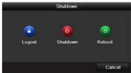
- Enter the Shutdown menu, Menu > ™ shutdown.
text_image
Shutdown Logout Shutdown Reboot CancelFigure 25, •ogout
2. 'lick Logout.

If you log out of the system, menu operation is invalid. √ou must enter a valid user name and password to unlock the system.
2.5 "esetting Your -assword
If you forget the admin password, you can reset it by importing the G...ID file. The G...ID file must be exported and saved in the local ...TMB flash drive after activating the device.
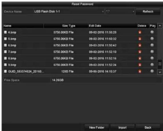
- On the user login interface, click Forgot -assword to pop up the Import G...ID interface.
text_image
Reset Password Device Name USB Flash Disk 1-1 Refresh Name Size Type Edit Date Delete Play 4.bmp 6750.06KB File 09-02-2016 11:50:28 5.bmp 6750.06KB File 09-02-2016 11:50:32 6.bmp 6750.06KB File 09-02-2016 11:50:42 7.bmp 6750.06KB File 09-02-2016 11:52:10 8.bmp 6750.06KB File 09-02-2016 11:52:16 9.bmp 6750.06KB File 09-02-2016 11:52:24 GUID_583574624_2016B_ 128D File 09-06-2016 14:10:37 Free Space 14.26GB New Folder Import DeskFigure 26, Import G...ID
- ™elect the G...ID file from the ... ™B flash drive.
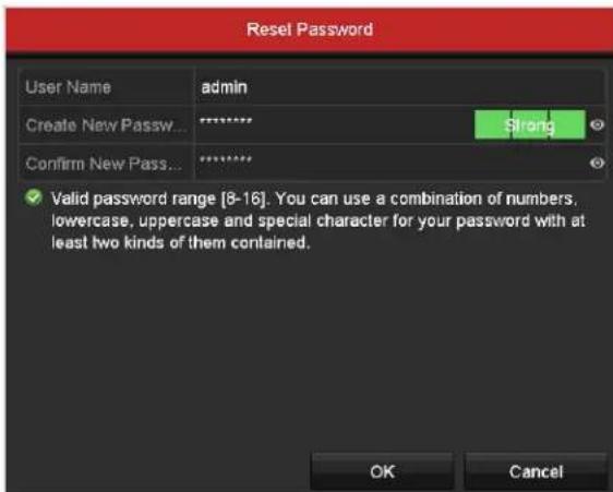
- 'lick Import to pop up the Reset Password interface.
text_image
Reset Password User Name admin Create New Pass... ******** Strong Confirm New Pass... ******** ✓ Valid password range [8-16]. You can use a combination of numbers, lowercase, uppercase and special character for your password with at least two kinds of them contained. OK CancelFigure 27, Reset Password
-
Enter and confirm the new password.
-
'lick 'K to save the new password. The Attention box will pop up as shown below.
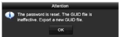
text_image
Attention The password is reset. The GUID file is ineffective. Export a new GUID file. OKFigure 28, G...ID File Imported
- 'lick 'K, and the Attention box will pop up to remind you to duplicate the device password to IP cameras that are connected with default protocol. 'lick Yes to duplicate the password or TMo to cancel.
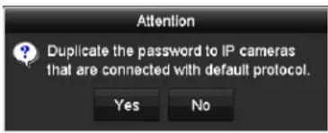
text_image
Attention Duplicate the password to IP cameras that are connected with default protocol. Yes NoFigure 2", Duplicate the Password

To retrieve a forgotten password, you must first export the G...ID file.
Once the password is reset, the G...ID file will be invalid. √ou can export a new G...ID file.
2.6 √dding and Connecting I–Cameras
2.6.• √ctivating I- Cameras
Before adding the cameras, make sure the IP cameras to be added are in active status.
- ™elect the √dd I– Camera option from the right-click menu in live view mode or click Menu > 'amera > IP 'amera to enter the I– Camera Management interface.

For IP cameras detected online in the same network segment, the Security status shows whether they are active or inactive.
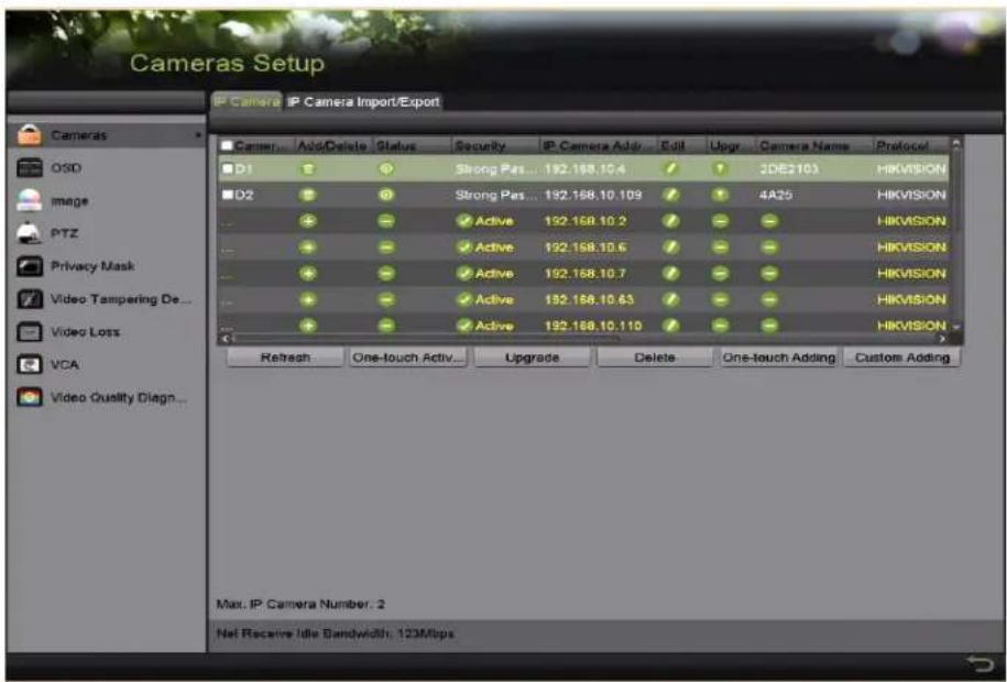
text_image
Cameras Setup IP Camera IP Camera Import/Export Camera... Add/Delete Status Security IP Camera Add/ Edit Upgr Camera Name Protocol D1 D2 Privacy Mask Video Tampering De... Video Loss VCA Video Quality Diagn... Strong Pass ... 192.168.10.4 / 3DE2103 HIKVISION Strong Pass ... 192.168.10.109 / 4A25 HIKVISION Active 192.168.10.2 / - HIKVISION Active 192.168.10.6 / - HIKVISION Active 192.168.10.7 / - HIKVISION Active 192.168.10.63 / - HIKVISION Active 192.168.10.110 / - HIKVISION Refresh One-touch Activ... Upgrade Delete One-touch Adding Custom Adding Max. IP Camera Number: 2 Net Receive Idle Bandwidth: 123MbpsFigure 30, IP 'amera Management Interface
- 'lick the inactive icon of the camera to enter the following interface to activate it. √ou can also select multiple cameras from the list and click 'ne-touch √ctivate to batch activate the cameras.
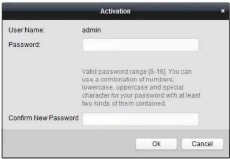
text_image
Activation User Name: admin Password: Valid password range [8-16]. You can use a combination of numbers, lowercase, uppercase and special character for your password with at least two kinds of them contained. Confirm New Password Ok CancelFigure 31, Activate the 'amera
-
™et a camera password to activate it.
-
Use √dmin -assword: When you check the this checkbox, the camera(s) will be configured with the same admin password as the operating D-R.
- Create ™ew –assword: If the admin password is not used, you must create and confirm a new password for the camera.
text_image
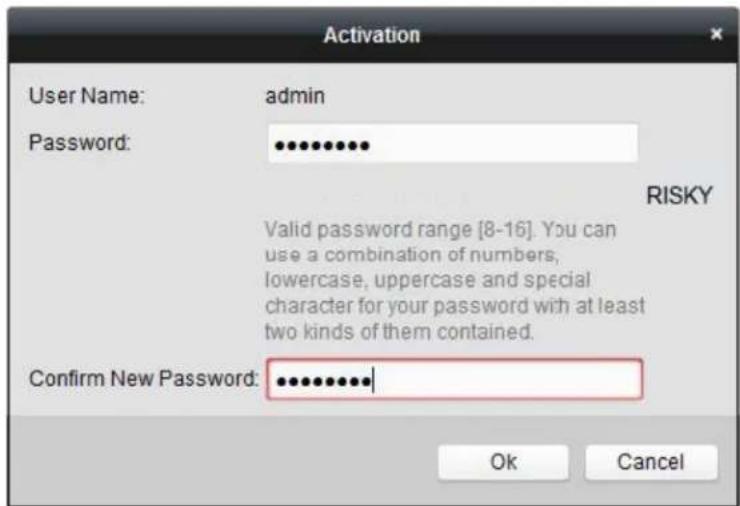
Activation User Name: admin Password: ••••••••• RISKY Valid password range [8-16]. You can use a combination of numbers, lowercase, uppercase and special character for your password with at least two kinds of them contained. Confirm New Password: ••••••••••| Ok CancelFigure 32, •evel 0 (Inadequate) ™trength Password
text_image
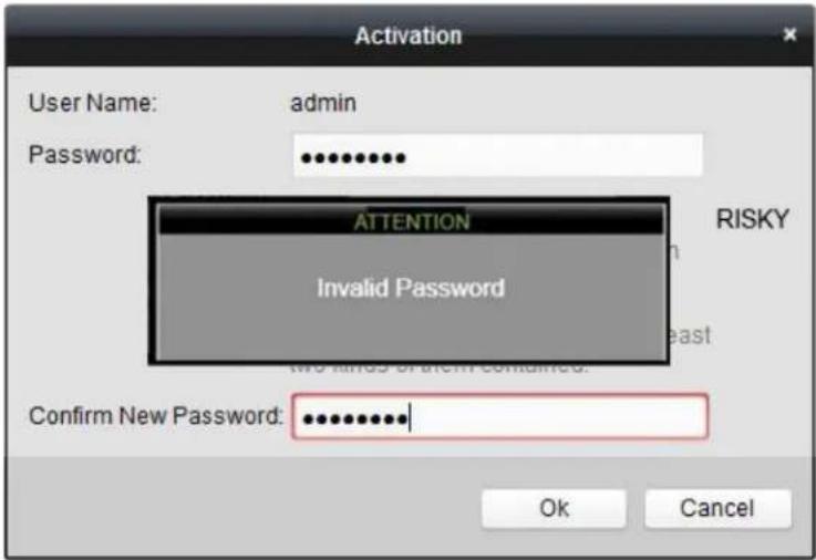
Activation User Name: admin Password: ********** ATTENTION Invalid Password RISKY No kinds of content contained. Confirm New Password: ********** Ok CancelFigure 33, Invalid Password Message
text_image
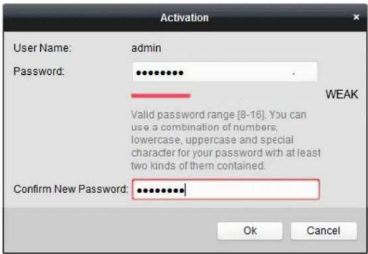
Activation User Name: admin Password: ••••••••• WEAK Valid password range [8-16]. You can use a combination of numbers, lowercase, uppercase and special character for your password with at least two kinds of them contained. Confirm New Password: ••••••••••• Ok CancelFigure 34, •evel 1 Password ™trength
text_image
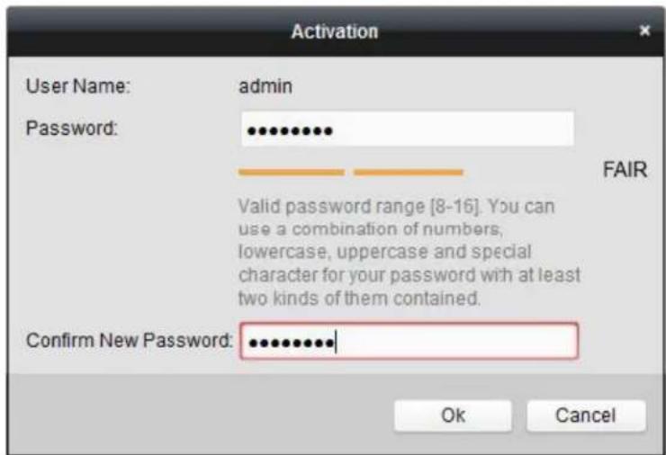
Activation User Name: admin Password: •••••••• FAIR Valid password range [8-16]. You can use a combination of numbers, lowercase, uppercase and special character for your password with at least two kinds of them contained. Confirm New Password: ••••••••• Ok CancelFigure 35, •evel 2 Password ™trength
text_image
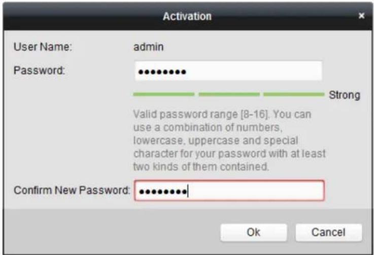
Activation User Name: admin Password: •••••••••• Strong Valid password range [8-16]. You can use a combination of numbers, lowercase, uppercase and special character for your password with at least two kinds of them contained. Confirm New Password: ••••••••••• Ok CancelFigure 36, •evel 3 and •evel 4 Password ™trength

WARNING
ST™G -√SSW”D "EC'MME™DED – We highly recommend you create a strong password of your own choosing (using a minimum of eight characters, including at least three of the following categories" upper case letters, lower case letters, numbers, and special characters.) in order to increase the security of your product. We also recommend that you reset your password regularly. Resetting the password monthly or weekly can better protect your product.
- 'lick' K to finish activating the IP camera. The camera security status will change to √ctive.
2.6.2 √dding an 'nline I– Camera
Before using •ive View or recording video, you must add the network cameras to the device connection list.
- Before Starting
Ensure the network connection is valid and correct.
- 'TITM
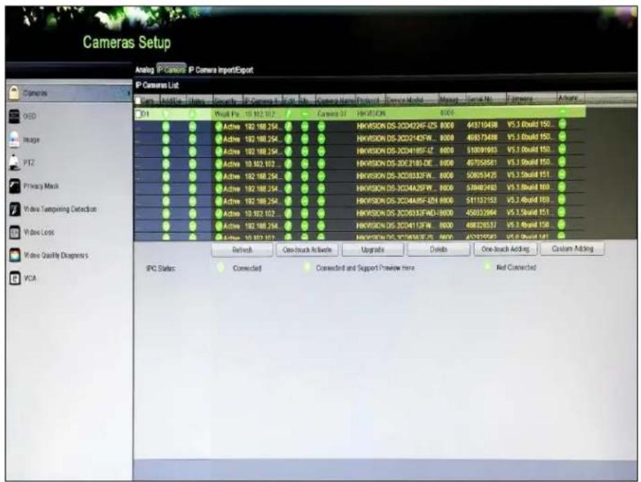
- ™elect the √dd I- Camera option from the right-click menu in •ive View mode or click Menu > Camera > IP Camera to enter the I- Camera Management interface.
text_image
Cameras Setup Analog IP Camera IP Camera ImportExport IP Cameras List Camera ID Device Name Address File Name Device Type Device Type Device Name Device Type Device Name Message Serial No Actions Actions ID1 Weak Pos 10.102.10.2 Camera GT HKVISION DS-3CD4224F-ZS 8000 443710498 VS.3.0build 150... Active 192.168.254... Active 192.168.254... Active 192.168.254... Active 192.168.254... Active 192.168.254... Active 192.168.254... Active 192.168.254... Active 192.168.254... Highvision DS-3CD4224F-ZS 8000 443710498 VS.3.0build 150... Active 192.168.254... Active 192.168.254... Active 192.168.254... Active 192.168.254... Highvision DS-3CD4224F-ZS 8000 443710498 VS.3.0build 150... Active 10.102.102... Active 10.102.102... Active 10.102.102... Active 10.102.102... Highvision DS-3CD4224F-ZS 8000 443710498 VS.3.0build 150... Active 10.102.102... Active 10.102.102... Highvision DS-3CD4224F-ZS 8000 443710498 VS.3.0build 150... Active 10.102.102... Active 10.102.102... Highvision DS-3CD4333F-ZS 8000 506553475 VS.3.5build 151... Active 192.168.254... Active 192.168.254... Active 192.168.254... Highvision DS-3CD4333F-ZS 8000 576802493 VS.3.5build 160... Active 192.168.254... Active 192.168.254... Highvision DS-3CD4333F-ZS 8000 541137153 VS.3.4build 160... Active 192.168.254... Active 192.168.254... Highvision DS-3CD4333F-ZS 8000 456553964 VS.3.5build 151... Active 192.168.254... Active 192.168.254... Highvision DS-3CD4333F-ZS 8000 486326537 VS.3.6build 150... Active 192.168.254... Highvision DS-3CD4333F-ZS 8000 457777777 VS.3.7build 151... Refresh One-touch Active Upgrade Delete One-touch Adding Custom Adding IPC Status: Connected Connected and Support Preview Hera Net ConnectedFigure 37, IP Camera Management Interface
-
Online cameras in the same network segment will be detected and displayed in the camera list.
-
™elect the IP camera from the list and click 📋 add the camera (with the same admin password as the DVR), or click the ’ne-touch √dding button to add all cameras (that have the same admin password) from the list.
Make sure the camera to add has already been activated by setting the admin password, and the admin password of the camera is the same as the DVR's.
- (Optional) Check the E nable H.265 checkbox (for initial access) for the connected IP camera supporting H.265. The IP camera will be encoded with H.265.
- 'Tl™ 2
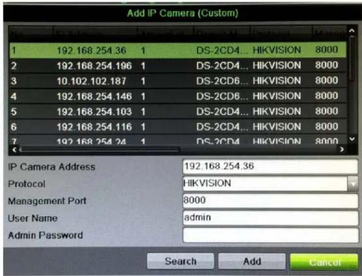
- On the I–Camera Management interface, click the Custom √dding button to pop up the Add IP 'amera ('custom) interface.
text_image
Add IP Camera (Custom) 1 192.168.254.36 1 DS-2CD4... HIKVISION 8000 2 192.168.254.196 1 DS-2CD4... HIKVISION 8000 3 10.102.102.187 1 DS-2CD6... HIKVISION 8000 4 192.168.254.146 1 DS-2CD6... HIKVISION 8000 5 192.168.254.103 1 DS-2CD4... HIKVISION 8000 6 192.168.254.116 1 DS-2CD4... HIKVISION 8000 7 192.168.254.24 1 DS-2CD4... HIKVISION 8000 IP Camera Address 192.168.254.36 Protocol HIKVISION Management Port 8000 User Name admin Admin Password Search Add CancelFigure 38, 'ustom Adding IP 'amera Interface
- √ou can edit the IP address, protocol, management port, and other information.
i NOTE
If the IP camera to add has not been activated, you can activate it from the IP camera list on the IP 'amera Management interface.
- 'lick to add the camera.
i NOTE
For added IP cameras, the Security status shows the password security level.
Table 1-6 IP 'ameras™ supported
| 'amera Model Number of IP 'ameras TM upported | |
| DTM-7204H≤I-K1 1, up to 4 MP | |
| DTM-7208H≤I-K2 | 2, up to 4 MP |
| DTM-7216H≤I-K2 | |
| DTM-7204H...I-K1 | 2, up to 6 MP DTM-7208H...I-K2 |
| DTM-7216H...I-K2 | |
Table 1-7 Explanation of the Icons
| Icon Explanation Icon Explanation | |||
 | EDIT (Pen)" Press to edit basic IP camera parameters |  | ADD (+)" Press to add the detected IP camera |
 | DI^TM CONNECTED (!)" Camera is disconnected; click the icon to get camera's exception information |  | DE•ETE (Trash Can)" Press to delete the camera |
 | P•A√ (Right Triangle)" Play connected camera's live video |  | ADVANCED (Gear)" Press to go to advanced settings window. |
 | ...PGRADE (...p Arrow)" ...grade the connected camera's firmware |  | DA^TMH" No advanced settings available for this camera |
 | REPAIR (?) " Press to attempt to repair the connection | Security Column | ^TMEC...RIT^TMhows camera status (active/inactive) or password strength (strong/medium/weak/risky) |
- (Optional) Check the Enable H.265 checkbox (for initial access) for a connected IP camera that supports H.265. The IP camera will be encoded with H.265.
2.6.3 Editing the Connected IP Camera
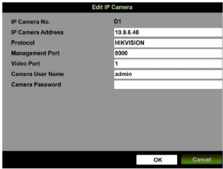
After adding the IP cameras, the basic information of the camera is listed on the interface, and you can configure the basic settings.
- Click ☑ to edit the parameters. √ou can edit the IP address, protocol, and other parameters.
text_image
Edit IP Camera IP Camera No. D1 IP Camera Address 10.9.6.48 Protocol HIKVISION Management Port 8000 Video Port 1 Camera User Name adults Camera Password OK CancelFigure 3", Edit IP Camera
- Channel Port: If the connected device is an encoding device with multiple channels, select the channel port No. in the drop-down list.
-
Click OK to save the settings and exit from the editing interface.
-
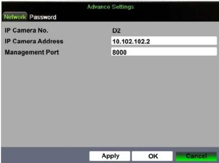
Drag the horizontal scroll bar to the right and click to edit the advanced parameters.
text_image
Network Password IP Camera No. D2 IP Camera Address 10.102.102.2 Management Port 8000 Apply OK CancelFigure 40, Network Configuration of the Camera
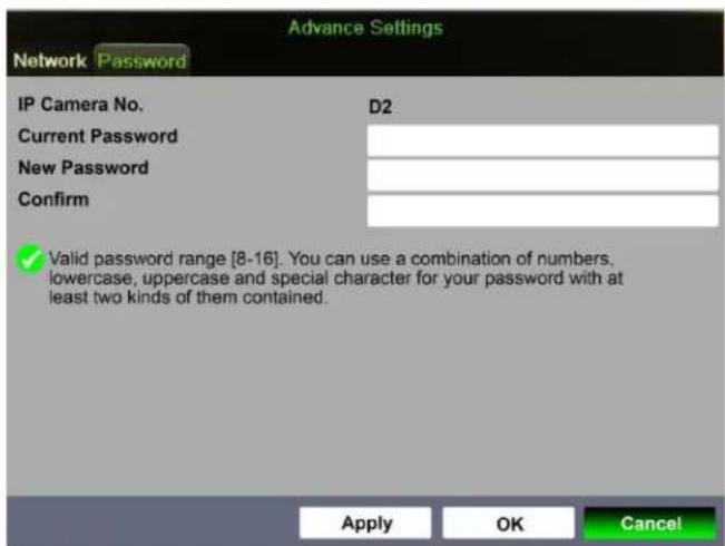
- Edit the camera's network information and password.
text_image
Advance Settings Network Password IP Camera No. D2 Current Password New Password Confirm ✓ Valid password range [8-16]. You can use a combination of numbers, lowercase, uppercase and special character for your password with at least two kinds of them contained. Apply OK CancelFigure 41, Password Configuration of the Camera
- Click 'K to save the settings and exit the interface.
Chapter 3 Live View
3.1 Introduction
-ive View shows real time video image from each camera. The DVR will automatically enter •ive View mode when powered on. It is also at the very top of the menu hierarchy, thus hitting E™C many times (depending on which menu you're on) will bring you back to •ive View mode.
3.1.1 Live View Icons
In •ive View mode, icons at the right top of the screen for each channel show channel's record and alarm status, so that you can know if the channel is recorded or see alarms as soon as possible.
Table 1-1 Description of •ive View Icons
| Icons Description | |
| [CA87] | Alarm (video loss, tampering, motion detection, VCA, or sensor alarm) |
| [057K] | Record (manual record, schedule record, motion detection, or alarm triggered record) |
| [06CD] | Alarm & Record |
 | Event/Exception (motion detection, sensor alarm, or exception information. For details, see Chapter 8.6 Handling Exceptions.) |
3.2 Operations in Live View Mode
In live view mode, there are many functions provided. The functions are listed below.
- Single Screen: ^TM how only one screen on the monitor.
- Multi-screen: ^TM how multiple screens on the monitor simultaneously.
- Start √auto-switch: ™creen is auto switched to next one; you must set dwell time for each screen on the configuration menu before enabling auto-switch (Menu > Configuration > •ive View > Dwell Time).
- Start Recording: Normal record and motion detection record are supported.
• Output Mode: ™et output mode to ™tandard, Bright, Gentle, or Vivid. - Playback: Play back the recorded videos for current day.
- For DS-72xxHUI-Kx Series DVRs with CVBS Output: The VGA/HDMI output is the main output, and the CVBS output is the aux output. The priority relationship is shown as Table 3-2.
Table 1-2 Priorities of Outputs for DS-72xxHUI-Kx Series
| S.N | HDMI | VGA | CVBS | Main | output | Auxiliary output |
| 1 √ | or × | √ | or × | √ or × | VGA/HDMI | CVBS |
i NOTE
√ means the interface is in use, × means the interface is out of use or the connection is invalid. The HDMI, VGA, and CVBS can be used at the same time.
When present the HDMI/VGA will provide the main monitor output with the CVBS serving only as a spot (Live View) monitor. If no HDMI or VGA monitor is connected at the time of bootup, the CVBS monitor can be used as the main monitor, allowing control of menu and playback. A reboot is required to return this function to the HDMI/VGA monitor(s).
3.2.1 Using the Mouse in Live View
Table 1-3 Mouse Operation in Live View
| Name Description | |
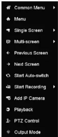
| Menu | Enter the main menu of the system by right clicking the mouse. |
| Single Screen | Switch to the single full screen by choosing channel number from the drop-down list. |
| Multi-Screen | Adjust the screen layout by selecting from the drop-down list. |
| Previous Screen | Switch to the previous screen. |
| Next Screen | Switch to the next screen. |
| Start/Stop Auto-Switch | Enable/disable the auto-switch of the screens. NOTESet the Live View configuration dwell time before using Start Auto-Switch . NOTESet the Live View configuration dwell time before using Start Auto-Switch . |
| Start Recording | Start recording of all channels, Continuous Record and Motion Detection Record are selectable from the drop-down list. |
| Add IP Camera | A shortcut to enter the IP camera management interface.(For HDVR series only) |
| Playback | Enter the playback interface and start playing back the video of the selected channel immediately. |
| PTZ Control | A shortcut to enter the PTZ control interface of the selected camera. |
| Output Mode | Output Mode is configurable with Standard, Bright, Gentle and Vivid options. |
text_image
Common Menu Menu Single Screen Multi-screen Previous Screen Next Screen Start Auto-switch Start Recording Add IP Camera Playback PTZ Control Output ModeFigure 42, Right-click Menu
3.2.2 Switching Main/√ux 'utput

CVB ^TM output serves only as aux output or •ive View output.
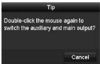
- Double click on the HDMI/VGA output screen, and the following message box pops up.
text_image
Tip Double-click the mouse again to switch the auxiliary and main output? CancelFigure 43, ^TM witch Main and Aux Output
- Double click on the screen again to switch to the aux output, or click Cancel to cancel the operation.
- ™elect Others from the Menu 'utput Mode by right-clicking Menu on the monitor.
- On the pop-up message box, click Yes to reboot the device to enable the selected menu output as the main output.

^TM elect the Menu 'utput Mode under Menu > Configuration > General > More ^TM ettings to √uto and HDMI/VG√ and then reboot the device to switch the main output.
3.2.3 "uick Setting Toolbar in Live View Mode
On each channel's screen, there is a quick setting toolbar that appears when you click the screen. ™ee Table 3-4 for the ≤uick ™etting Toolbar icon descriptions.
D^TM-72xxH...I-Kx, D^TM-72xxH ≤ I-Kx Digital -ideo Recorder (D-R) ...ser Manual

text_image
Screenshot of a software toolbar with icons for video, audio, audio, search, and related functionsFigure 44, ≤uick ™etting Toolbar
Table 1-4 Description of ≤uick ™etting Toolbar Icons
| Icons | Description | Icons | Description | Icons | Description |
| Start/Stop Manual Recording | Instant Playback | Audio On/Mute | |||
| PTZ Control | Digital Zoom | Image Settings | |||
| Close Live View | Face Detection | Information | |||
| Capture | Live View Strategy | Information | |||
| Fisheye |

Instant Playback shows the record only for the last five minutes. If no record is found, it means there is no recording the last five minutes.

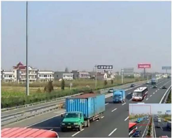
Digital Zoom can zoom in the selected area to the full screen. 'lick and draw to select the area to zoom in.
natural_image
Highway scene with vehicles and shipping containers, residential buildings in background (no visible text or symbols)Figure 45, Digital Zoom

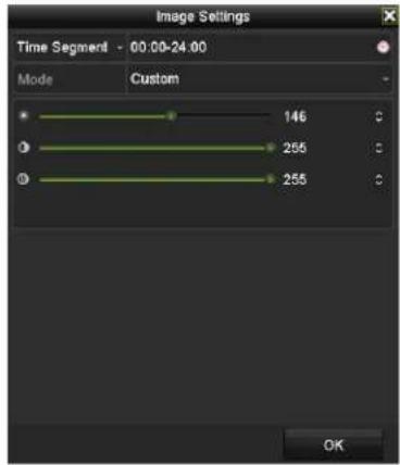
Image ™ettings icon can be selected to enter the Image ™ettings menu. √ou can drag the mouse or click adjust the image parameters, including brightness, contrast, and saturation.
text_image
Image Settings Time Segment - 00:00-24:00 Mode Custom 146 255 255 OKFigure 46, Image ™ettings

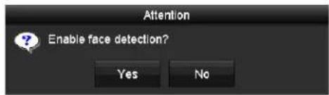
Face Detection can be enabled if you click the icon. A dialog box pops up. 'lick Yes and the full-screen live view of the channel is enabled. 'lick
to exit from the full-screen mode.
text_image
Attention Enable face detection? Yes NoFigure 47, Enable Face Detection
i NOTE
√ou can configure face detection only if it is supported by the connected camera.

Move the mouse onto the Information icon to show the real-time stream information, including frame rate, bit rate, resolution, and stream type.
i NOTE
When an H.264 IP camera is connected, the stream type is displayed as H.264. When an IP camera supporting H.264+ is connected, the stream type is displayed as H.264+. When an IP camera supporting H.265 is connected, the stream type is displayed as H.265. When an IP camera supporting H.265+ is connected, the stream type is displayed as H.265+.

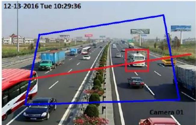
For analog cameras supporting –'A, click the icon to show the –'A information. The configured line or quadrilateral in the –'A configuration and target frame(s) will be shown on •ive –iew. 'lick the icon again to hide the - 'A information.
text_image
12-13-2016 Tue 10:29:36 Camera 01Figure 48, Enable – 'A Information Overlay
i NOTE
In •ive -iew, only analog cameras support –'A information overlay.
Enable -'A function before showing the -'A information.
- 'A information is hidden by default. If the connected analog camera does not support -'A, the icon displays grey and cannot be operated.
For analog cameras, the -'A information includes line crossing detection and intrusion detection.
The D-R supports –'A information overlay of only one channel. If you enable the function of one channel, the other channels will disable the function automatically.
Both single window and multi-window display modes support –'A information overlay.
Only the main output supports –'A information overlay. When switching to the aux output, the –'A information overlay of main output is disabled.
For the analog cameras, if the camera number does not exceed the limit for line crossing detection and intrusion detection, the –'A information overlay can be enabled for all the analog cameras with line crossing detection and intrusion detection. If the camera number exceeds the limit for line crossing detection, intrusion detection, and sudden scene change detection, only the cameras enabled line crossing detection and intrusion detection support –'A information overlay. Disabling line crossing detection and intrusion detection remotely will not affect the –'A information overlay in the local live view.
3.3 Channel-Zero Encoding
'hannel-zero encoding provides a remote view of multiple channels in real time from a Web browser or 'M™ ('lient Management™ystem) software by decreasing the bandwidth requirement without affecting the image quality.
-
Enter the Li ve View ™ettings interface, Menu > 'onfiguration > •ive -iew.
-
™elect the Channel-Zero Encoding tab.
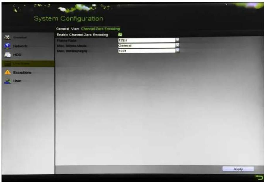
text_image
System Configuration General View Channel-Zero Encoding Enable Channel-Zero Encoding Frame Rate 12fps Max. Bitrate Mode General Max. MaxRate/Max: 10.24 ApplyFigure 4", •ive -iew 'hannel-Zero Encoding
- 'heck the Enable Channel-Zero Encoding checkbox.
- 'onfigure the Frame Rate, Max. Bitrate Mode, and Max. Bitrate.
- 'lick to activate the settings.
- After setting the 'hannel-Zero encoding, you can get a view in the remote client or Web browser of 16 channels on one screen.
3.4 √djusting Live View Settings
-ive -iew settings can be customized according to need. √ou can configure the output interface, dwell time for screen to be shown, mute or turn on the audio, the screen number for each channel, etc.
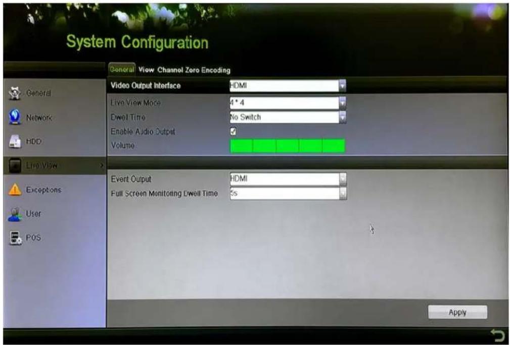
text_image
System Configuration General View Channel Zoro Encoding Video Output Interface HDMI Live View Mode 4 * 4 Dwell Time No Switch Enable Audio Output ✓ Volume Event Output HDMI Full Screen Monitoring Dwell Time 5s ApplyFigure 50, •ive View – General
-
Enter the Live View Settings interface, Menu > 'onfiguration > •ive View > General. The settings available in this menu include"
-
Video Output Interface: ^TM elects the output to configure the settings. √ou can select Main CVBS and HDMI/VG√ for video output interface.
• Live View Mode: ™ elects the display mode to be used for •ive View. - Dwell Time: The time in seconds to dwell (pause) between switching of channels when enabling auto-switch in •ive View.
- Enable √audio Output: Enables/disables audio output for the selected camera in the live view mode.
• Volume: Adjusts the volume of the audio output. - Event Output: Designates the output to show event video. If available, you can select a different video output interface from the Video Output Interface when an event occurs.
• Full Screen Monitoring Dwell Time: ™ets the time in seconds to show alarm event screen.
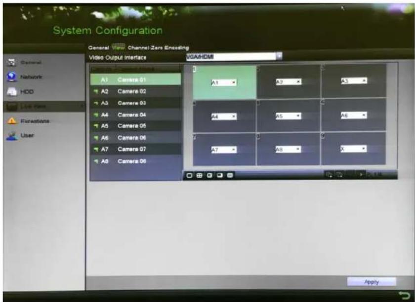
text_image
System Configuration General View Channel-Zers Enseeding Video Output Interface VGA/HDMI A1 Camera 01 A2 Camera 02 A3 Camera 03 A4 Camera 04 A5 Camera 05 A6 Camera 06 A7 Camera 07 A8 Camera 08 A1 A2 A3 A4 A5 A6 A7 A8 X ApplyFigure 51, •ive View > View ™ettings
- ™et the camera order.
a) Click the View tab and select the Video Output Interface from the drop-down list.
b) Click a window to select it, and then double click a camera name in the camera list you would like to display. ™etting an "X" means the window will not display any camera.
c) √ou can also click 📄 to start live view of all channels in order and click 📋 stop live view of all channels. Click 📋 to go to the previous or next page.
d) Click √pply.
3.5 Manual Video "uality Diagnostics
The video quality of the analog channels can be diagnosed manually, and you can view the diagnostic results list.
- Enter the Manual Video "uality Diagnostics interface, Menu > Manual > Manual Video ≤ uality Diagnostics.

text_image
Manual Video Quality Diagnostics ✓Analog ✓A1 ✓A2 ✓A3 ✓A4 ✓A5 ✓A6 ✓A7 ✓A8 ✓A9 ✓A10 ✓A11 ✓A12 ✓A13 ✓A14 ✓A15 ✓A16Figure 52, Manual Video ≤ uality Diagnostics
- Check the checkboxes to select the channels for diagnostics.
- Click Diagnose, and the results will be listed. √ou can view the video status and diagnostics time of the selected channels.
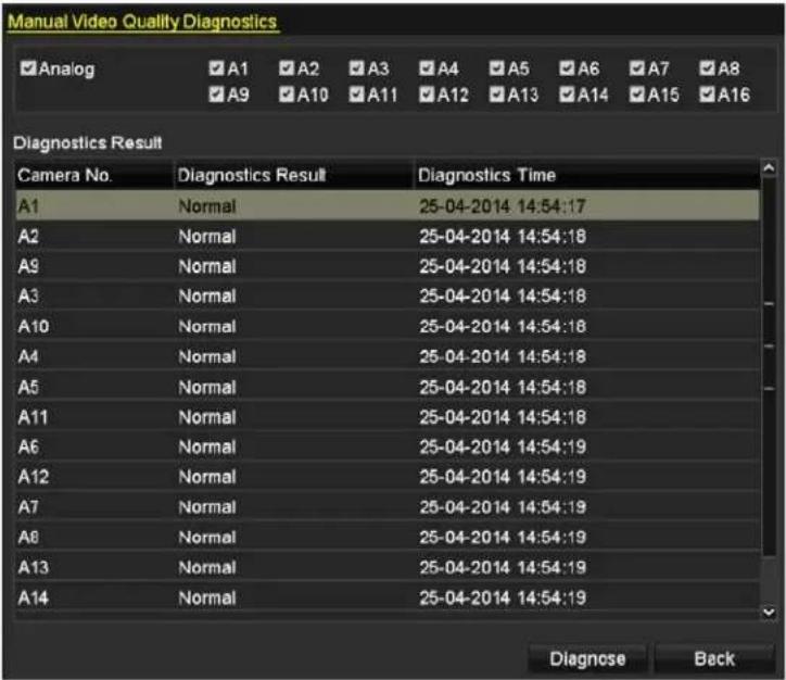
text_image
Manual Video Quality Diagnostics Analog A1 A2 A3 A4 A5 A6 A7 A8 A9 A10 A11 A12 A13 A14 A15 A16 Diagnostics Result Camera No. Diagnostics Result Diagnostics Time A1 Normal 25-04-2014 14:54:17 A2 Normal 25-04-2014 14:54:18 A9 Normal 25-04-2014 14:54:18 A3 Normal 25-04-2014 14:54:18 A10 Normal 25-04-2014 14:54:18 A4 Normal 25-04-2014 14:54:18 A5 Normal 25-04-2014 14:54:18 A11 Normal 25-04-2014 14:54:18 A6 Normal 25-04-2014 14:54:19 A12 Normal 25-04-2014 14:54:19 A7 Normal 25-04-2014 14:54:19 A8 Normal 25-04-2014 14:54:19 A13 Normal 25-04-2014 14:54:19 A14 Normal 25-04-2014 14:54:19 Diagnose BackFigure 53, Diagnostics Result

NOTE
'onnect the camera to the device for the video quality diagnostics.
Three exception types can be diagnosed" Blurred Image, Abnormal Brightness, and 'olor'ast.
Chapter 4 –TZ Controls
4.• Configuring –TZ Settings
Follow this procedure to set the PTZ parameters. 'onfigure the PTZ parameters before controlling the PTZ camera.
- Enter the -TZ Settings interface, Menu > 'ameras™etup > PTZ.
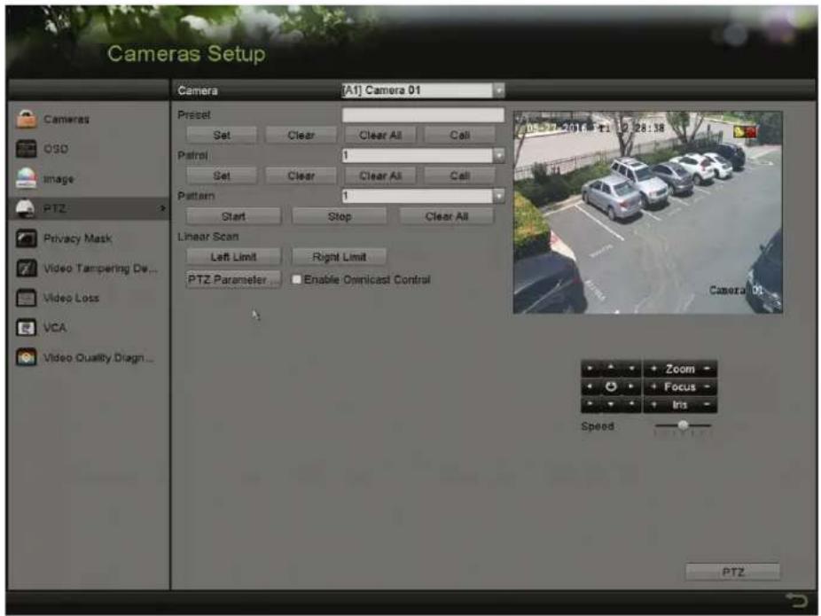
text_image
Cameras Setup Camera (A1) Camera 01 Preset Set Clear Clear All Call Patrol 1 Set Clear Clear All Call Pattern 1 Start Stop Clear All Linear Scan Left Limit Right Limit PTZ Parameter Enable Omnicast Control PTZ Zoom Focus Ins Speed PTZFigure 54, PTZ ^TM ettings
- ™elect the camera for PTZ setting in the 'amera drop-down list.
- 'lick -TZ -parameters to set the PTZ parameters.
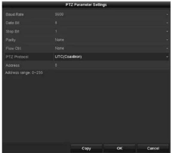
text_image
PTZ Parameter Settings Baud Rate 9600 Data Bit 8 Stop Bit 1 Parity None Flow Ctrl None PTZ Protocol UTC(Coaxithron) Address 0 Address range: 0~255 Copy OK CancelFigure 55, PTZ – General
- ™elect the PTZ camera parameters from the drop-down list.
i NOTE
These parameters should be identical to the PTZ camera parameters.
For an ...p-the-'oax camera/dome, select the ...T' PTZ protocol. Make sure the protocol selected here is supported by the connected camera/dome.
When the ...T' protocol is selected, all the other parameters such as baud rate, data bit, stop bit, parity, and flow control are not configurable.
- (Optional) 'lick C opy to copy the settings to the other channels. ™ elect the channels you want to copy to and click 'K to return to the -TZ -parameters Settings interface.
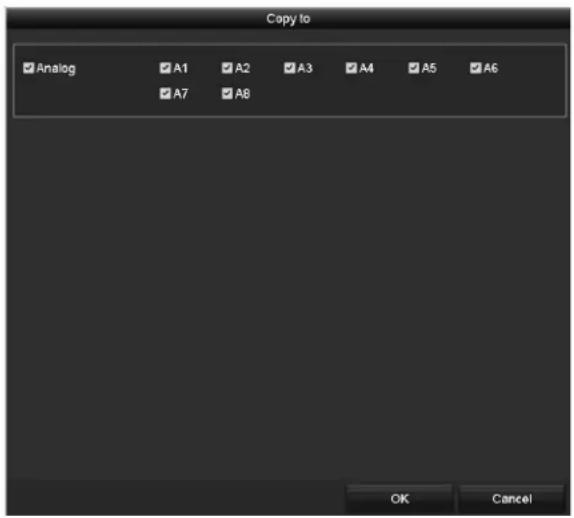
text_image
Copy to ✓ Analog ✓ A1 ✓ A2 ✓ A3 ✓ A4 ✓ A5 ✓ A6 ✓ A7 ✓ A8 OK CancelFigure 56, 'opy to Other 'hannels
- 'lick 'K to save the settings.
- (Optional) 'heck the Enable 'mnicast Control checkbox to enable PTZ control of the selected camera via Omnicast -M™ of Genetec.
4.2 Setting -TZ -resets, -atrols, and -atterns
Make sure that the presets, patrols, and patterns are supported by PTZ protocols.
4.2.• Customizing -resets
^TM et the Preset location you want the PTZ camera to point to when an event takes place.
- Enter the -TZ Settings interface, Menu > 'ameras™etup > PTZ.
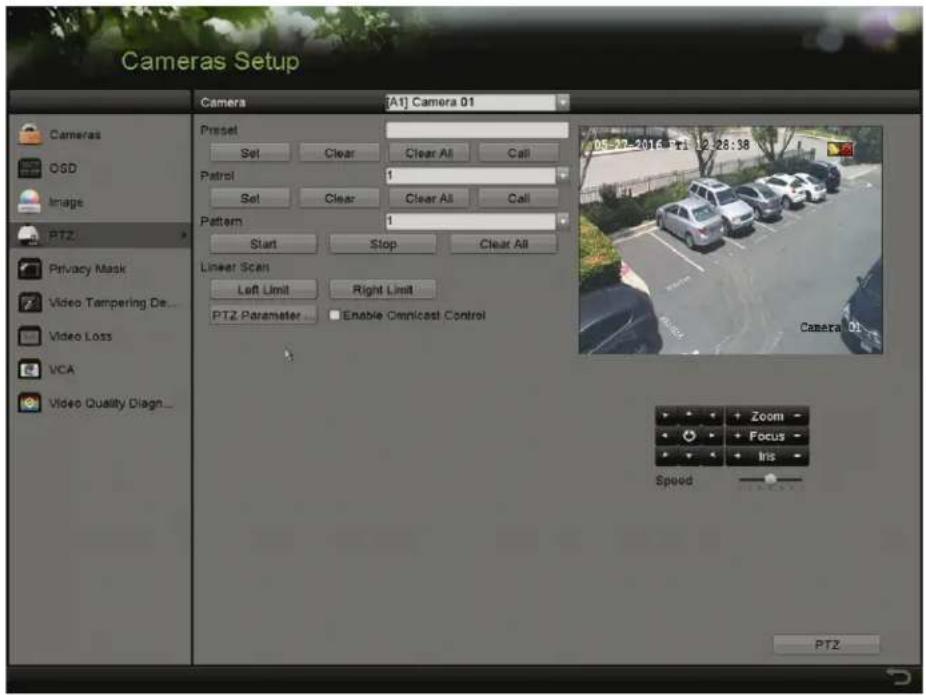
text_image
Cameras Setup Camera [A1] Camera 01 Preset Set Clear Clear All Call Patrol 1 Set Clear Clear All Call Pattern 1 Start Stop Clear All Linear Scan Left Limit Right Limit PTZ Parameter Enable Cimnicast Control 05-27-2014:Tr1 12:28:38 Camera 01 Zoom Focus Iris Speed PTZFigure 57, PTZ ^TM ettings
- ...se the directional button to move the camera to the location where you want to set the preset; the zoom and focus operations can be recorded in the preset as well.
- Enter the preset No. (1 to 255) in the preset text field.
- 'lick Set to link the location to the preset.
- Repeat steps 2 and 3 to save more presets.

'lick Clear to clear the preset location information, or click Clear √II to clear the location information of all presets.
4.2.2 Calling - resets
This feature has the camera point to a specified location such as a window when an event occurs.
-
Perform one of the following actions to display the PTZ control panel"
-
'lick -TZ in the lower-right corner of the PTZ setting interface.
- Press -TZ on the front panel.
- 'lick the PTZ 'ontrol icon in the quick setting bar.
-
^TM elect the PTZ option in the right-click menu.
-
'hoose Camera in the drop-down list.
-
'lick the General tab to show the PTZ control general settings.
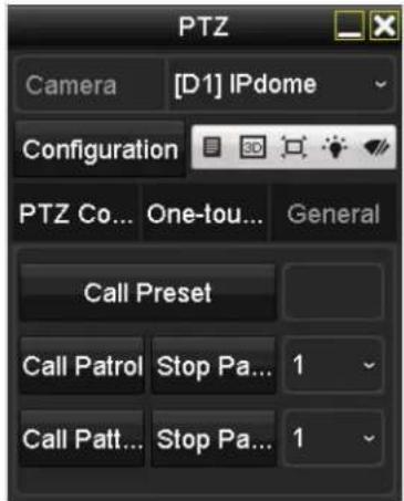
text_image
PTZ Camera [D1] IPdome Configuration PTZ Co... One-tou... General Call Preset Call Patrol Stop Pa... 1 Call Patt... Stop Pa... 1Figure 58, PTZ Panel – General
-
'lick to enter the preset No. in the corresponding text field.
-
'lick Call -reset to call it.

When a ...T' camera is connected and the PTZ protocol is set to ...T', you can call preset "5 to enter the ...T' camera menu. ...se the PTZ control panel directional buttons to operate the menu.
4.2.3 Customizing -atrols
Patrols can be set to move the PTZ to different key points and have it stay there for a set duration before moving on to the next key point. The key points correspond to the presets. The presets can be set following the steps above in 'ustomizing Presets'.
- Enter the -TZ Settings interface, Menu > 'amera > PTZ.
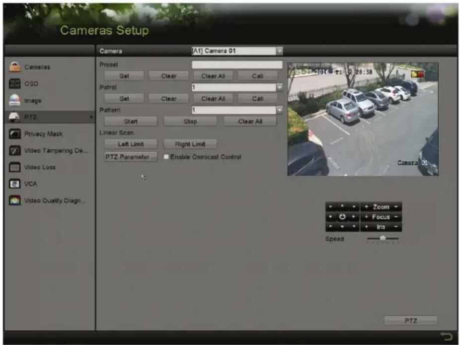
text_image
Cameras Setup Camera [A1] Camera 01 Preset Set Clear Clear All Call Patrol 1 Set Clear Clear All Call Pattern 1 Start Stop Clear All Linear Scan Left Limit Right Limit PTZ Parameter Enable Omnicast Control PTZ Privacy Mask Video Tampering De... Video Loss VCA Video Quality Diagn... 05-27-2013-ri 12:28:38 Camera 01 Zoom - Focus - Iris - Speed PTZFigure 5", PTZ™ettings
- ™elect patrol No. in the patrol drop-down list.
- 'lick Set to add key points for the patrol.
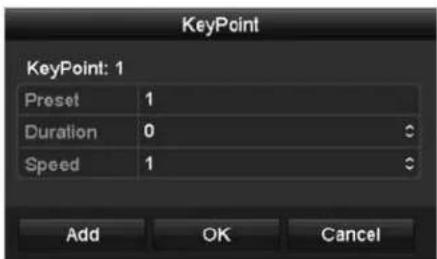
text_image
KeyPoint KeyPoint: 1 Preset 1 Duration 0 Speed 1 Add OK CancelFigure 60, KeyPoint 'onfiguration
-
'onfigure key point parameters.
-
Key-oint ^TM o. determines the order the PTZ will follow while cycling through the patrol. KeyPoints correspond to the presets.
• Duration is the time period to stay at the corresponding key point.
• Speed defines the speed the PTZ will move from one key point to the next. -
'lick √ dd to add the next key point to the patrol, or click 'K to save the key point to the patrol.

√ou can delete all the key points by clicking Clear for the selected patrol, or click Clear √II to delete all the key points for all patrols.
4.2.4 Calling -atrols
'alling a patrol causes the PTZ to move according the predefined patrol path.
-
Perform one of the following actions to display the PTZ control panel"
-
'lick -TZ in the lower-right corner of the -TZ Settings interface
- Press -TZ on the front panel
- 'lick the -TZ 'ontrol icon in the quick setting bar
-
^TM elect the -TZ option in the right-click menu to show the PTZ control panel
-
'lick the General tab to show the general settings of the PTZ control.
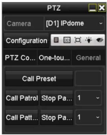
text_image
PTZ Camera [D1] IPdome Configuration PTZ Co... One-tou... General Call Preset Call Patrol Stop Pa... 1 Call Patt... Stop Pa... 1Figure 61, PTZ Panel – General
- ™elect a patrol in the drop-down list and click Call -atrol to call it.
- √ou can click Stop -atrol to stop calling it.
4.2.5 Customizing -atterns
Patterns can be set by recording the movement of the PTZ. √ou can call the pattern to have the PTZ movement follow to the predefined path.
- Enter the PTZ ^TM ettings interface, Menu > 'amera > PTZ.
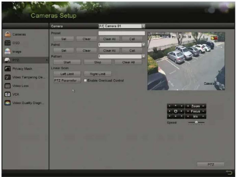
text_image
Cameras Setup Camera [A1] Camera 01 Preset Set Clear Clear All Call Patrol 1 Set Clear Clear All Call Pattern 1 Start Stop Clear All Linear Scan Left Limit Right Limit PTZ Parameter Enable Omnicast Control PTZ Video Tampering De... Video Loss VCA Video Quality Diagn... 05-27-2013: tri 12:28:38 Camera 01 Zoom - Focus - Iris - Speed PTZFigure 62, PTZ ^TM ettings
- 'hoose pattern number in the drop-down list.
- 'lick Start and click corresponding buttons in the control panel to move the PTZ camera, and click Stop to stop it. The PTZ movement is recorded as the pattern.
4.2.6 Calling -atterns
Follow the procedure to move the PTZ camera according to the predefined patterns.
-
Perform one of the following actions to display the PTZ control panel"
-
'lick -TZ in the lower-right corner of the -TZ Settings interface.
- Press -TZ on the front panel.
- 'lick the PTZ 'ontrol icon in the quick setting bar.
-
^TM elect the PTZ option in the right-click menu.
-
'lick the General tab to show the general settings of the PTZ control.
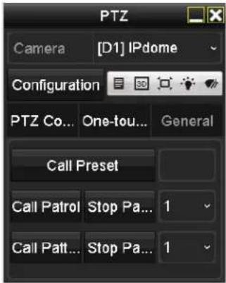
text_image
PTZ Camera [D1] IPdome Configuration PTZ Co... One-tou... General Call Preset Call Patrol Stop Pa... 1 Call Patt... Stop Pa... 1Figure 63, PTZ Panel – General
- 'lick Call -attern to call it.
- 'lick Stop -attern to stop calling it.
4.2.7 Customizing Linear Scan Limit
-inear™ can be enabled to trigger the scan in the horizontal direction in the predefined range.

This function is supported by certain models.
- Enter the -TZ Settings interface, Menu > 'amera > PTZ.
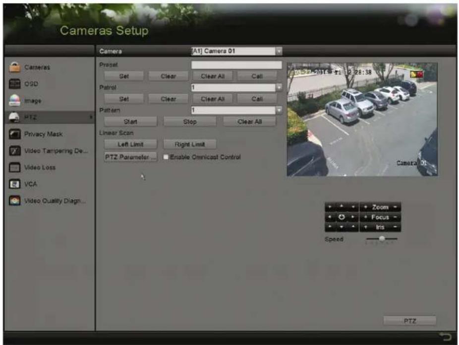
text_image
Cameras Setup Camera [A1] Camera 01 Preset Set Clear Clear All Call Patrol 1 Set Clear Clear All Call Pattern 1 Start Stop Clear All Linear Scan Left Limit Right Limit PTZ Parameter Enable Omnicost Control 05-27-2013: T1 12:28:38 Camera 01 Zoom - Focus - Irs - Speed PTZFigure 64, PTZ ^TM ettings
- ...se the directional button to move the camera to the location where you want to set the limit, and click Left Limit or "ight Limit" to link the location to the corresponding limit.

The speed dome starts linear scan from the left limit to the right limit, and you must set the left limit to the left of the right limit, as well the angle from the left limit to the right limit should be no more than 180^ .
4.2.8 Calling Linear Scan
Follow this procedure to call the linear scan in the predefined scan range.
-
Perform one of the following actions to display the PTZ control panel"
-
'lick -TZ in the lower-right corner of the -TZ Settings interface.
- Press -TZ on the front panel.
- 'lick the PTZ 'ontrol icon in the quick setting bar.
-
^TM elect the PTZ option in the right-click menu.
-
'lick the 'ne-touch tab to show the one-touch function of the PTZ control.
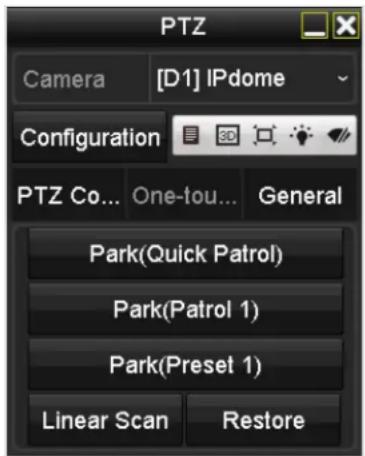
text_image
PTZ Camera [D1] IPdome Configuration PTZ Co... One-tou... General Park(Quick Patrol) Park(Patrol 1) Park(Preset 1) Linear Scan RestoreFigure 65, PTZ Panel – One-Touch
- 'lick Linear Scan to start the linear scan and click again to stop it.

'lick "estore to clear the defined left right limit data. The dome needs to reboot for settings to take effect.
4.2.9 'ne-Touch -ark
'ertain speed dome models can be configured to start a predefined park action (scan, preset, patrol, etc.) automatically after a period of inactivity (park time).
-
Perform one of the following actions to display the PTZ control panel"
-
'lick -TZ in the lower-right corner of the -TZ Settings interface.
- Press -TZ on the front panel.
- 'lick the PTZ 'ontrol icon in the quick setting bar.
-
^TM elect the PTZ option in the right-click menu.
-
'lick the 'ne-touch tab to show the PTZ control one-touch function.
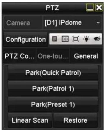
text_image
PTZ Camera [D1] IPdome Configuration PTZ Co... One-tou... General Park(Quick Patrol) Park(Patrol 1) Park(Preset 1) Linear Scan RestoreFigure 66, PTZ Panel – One-touch
-
There are three one-touch park types selectable. 'lick the corresponding button to activate the park action.
-
-ark ("uick -atrol): The dome starts patrol from predefined preset 1 to preset 32 in order after the park time. ...ndefined presets will be skipped.
- -ark (-atrol •): The dome starts moving according to predefined patrol 1 path after the park time.
- -ark (-reset •): The dome moves to the predefined preset 1 location after the park time.

The park time can be set only through the speed dome configuration interface. The default value is 5s.
- 'lick the button again to de-activate it.
4.3 PTZ Control Panel
To enter the PTZ control panel, there are two ways supported.
• OPTIO™ 1
In the PTZ Settings interface, click PTZ on the lower-right corner, next to the Back button.
• OPTIO™ 2
In •ive -iew mode"
- Press PTZ Control on the front panel.
- Press PTZ Control on the remote control.
- 'hoose the PTZ 'ontrol icon in the quick setting bar.
-
™elect the PTZ 'ontrol option in the right-click menu.
-
'lick Configuration on the control panel to enter the PTZ Settings interface.

In PTZ control mode, the PTZ panel will be displayed when a mouse is connected with the device. If no mouse is connected, the PTZ icon appears in the lower-left corner of the window, indicating that this camera is in PTZ control mode.
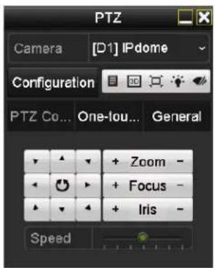
text_image
PTZ Camera [D1] IPdome Configuration PTZ Co... One-lou... General + Zoom - + Focus - + Iris - Speed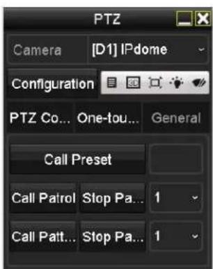
text_image
PTZ Camera [D1] IPdome Configuration PTZ Co... One-tou... General Call Preset Call Patrol Stop Pa... 1 Call Patt... Stop Pa... 1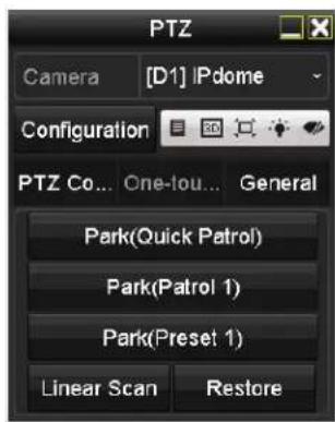
text_image
PTZ Camera [D1] IPdome Configuration PTZ Co... One-Iou... General Park(Quick Patrol) Park(Patrol 1) Park(Preset 1) Linear Scan RestoreFigure 67, PTZ 'ontrol Panel
Refer to Table 4-1 for the description of the PTZ panel icons.
Table 1-5 Description of the PTZ panel icons
| Icon Description Icon Description Icon Description | |||||
 | Direction button and auto-cycle button | Zoom+, Focus+, Iris+ | Zoom-, Focus-, Iris- | ||
| The speed of the PTZ movement | •ight on/off | Wiper on/off | |||
| 3D-Zoom | Image 'entralization | Menu | |||
| TMwitch to PTZ control interface | TMwitch to one-touch control interface | TMwitch to general settings interface | |||
| Exit | Minimize windows | ||||
Chapter 5 "ecording Settings
5. Configuring Encoding -parameters
5. Before Starting
- Make sure that the HDD has already been installed. If not, install and initialize an HDD (Menu >TMystem 'onfiguration > HDD).

text_image
Label Capacity Status Property Type Free Space Gro... Edit Delete 1 2794.52GB Normal R/W Local 2613.00GB 1 - -Figure 68, HDD – General
- 'lick tab to check the storage mode of the HDD (Menu >TMystem 'onfiguration > HDD >TMtorage Mode).
1) If the HDD mode is ≤ uota, set the maximum record capacity.
2) If the HDD mode is Group, set the HDD group.
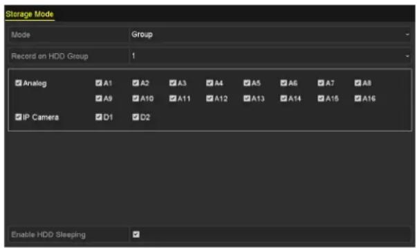
text_image
Storage Mode Mode Group Record on HDD Group 1 Analog A1 A2 A3 A4 A5 A6 A7 A8 A9 A10 A11 A12 A13 A14 A15 A16 IP Camera D1 D2 Enable HDD SleepingFigure 6", HDD - Advanced
5.2 Configure "ecord -parameters
- Enter the "ecord-parameters" interface to configure the encoding parameters, Menu > Recording 'onfiguration.
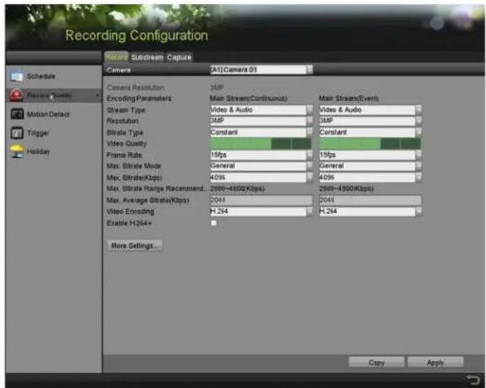
text_image
Recording Configuration Record Substream Capture Camera [A1]Camera 01 Schedule Resource Quality Motion Detect Trigger Holder Camera Resolution Encoding Parameters Stream Type Resolution Bitrate Type Video Quality Frame Rate Max. Bitrate Mode Max. Bitrate(Kbps) Max. Bitrate Range Recommendation. Max. Average Bitrate(Kbps) Video Encoding Enable H264+ More Settings... 3MP Main Stream(Continuous) Video & Audio 3MP Constant 15fps General 409s 2888-4500(Kbps) 2044 H.264 Main Stream(Events) Video & Audio 3MP Constant 15fps General 409s 2888-4500(Kbps) 2044 H.264 Copy ApplyFigure 70, Record Parameters
- ™et the parameters for recording.
1) ™elect the "ecord tab to configure.
2) ™elect a camera from the camera drop-down list.
3) -iew the 'amera Resolution.
i NOTE
When TurboHD input is connected, you can view the information including the input signal type, resolution, and frame rate (e.g., 5 MP 20 Hz). When '–B™' input is connected, you can view the information such as NT™' or PA•.
4) 'onfigure the following parameters for the Main Stream (Continuous) and the Main Stream (Event).
- Stream Type"™et the stream type to be –ideo or –ideo & Audio.
- "esolution" ^TM et recording resolution.
i NOTE
D™-72xxH...I-Kx™eries D-Rs support 5 MP and 4 MP resolution on all channels.
D^TM-72xxH ≤ I-Kx^TM eries D-Rs support up to 3 MP resolution for the first four channels.
Analog signal inputs (TurboHD, '–B™) and IP signal inputs can be recognized and connected automatically.
If the configured encoding resolution conflicts with the resolution of the front-end camera, the encoding parameters will adjust automatically to meet the front-end camera. E.g., if the resolution of the front-end camera is 720p, then the encoding resolution of the main stream will adjust to 720p automatically.
The “60 × 1080 (1080p •ite) resolution is available when 1080p •ite is enabled in the Record > Advanced ™ettings interface.
- Bitrate Type: ™et the bitrate type to be –ariable or 'onstant.
- Video "uality" ^TM et the recording video quality, with six levels configurable.
i NOTE
The ™™stream Type, Resolution, Bitrate Type, and –ideo ≤ uality are not configurable for the IP 'amera Main ™™stream (Event).
- Frame "ate: ™et the frame rate of recording.
i NOTE
For D ^TM -72xxH ≤ I-Kx ^TM eries D-Rs, when a 3 MP signal input is connected, the main stream frame rate cannot exceed 15 fps.
For D ^TM -72xxH...I-Kx ^TM eries D-Rs, when a 5 MP signal input is connected, the frame rate of the main stream cannot exceed 12 fps. When 4 MP signal input is connected, the main stream frame rate cannot exceed 15 fps.
- Max. Bitrate Mode: ™et the mode to General or 'ustom.
- Max Bitrate (Kbps): ^TM elect or customize the maximum bit rate for recording.
- Max. Bitrate "ange" recommended: A recommended max. bit rate range is provided for reference.
- Max. √verage Bitrate (Kbps): ™et the max. average bit rate which refers to the average amount of data transferred per unit of time.
- Video Encoding: √ou can configure H.264 or H.265 for the main stream (continuous) of IP and analog cameras.
i NOTE
When the connected IP camera does not support H.265, only H.264 can be selected for the main stream (continuous).
- 'heck the E nable H.264+ or Enable H.265+ checkbox to enable this function. Enabling it helps to ensure high video quality with a lowered bitrate.
i NOTE
For -K series DVRs, the analog and IP cameras support enabling H.264+/H.265+ if the video encoding is H.264/H.265 for the main stream.
After enabling H.264+ or H.265+, the Bitrate Type, Video ≤uality, Max. Bitrate Mode, Max. Bitrate(Kbps), and Max. Bitrate Range Recommend are not configurable.
If H.265+ is enabled, line crossing detection and region entrance detection are not supported.
For IP cameras, H.264+ or H.265+ should be supported by the camera and added to the DVR with HIKVI™ION protocol.
^TM ystem will reboot to activate the new settings after enabling H.264+ or H.265+.
4. 'lick M ore Settings to configure more parameters.
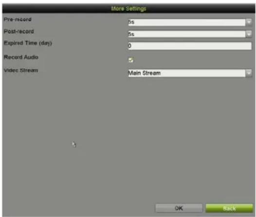
text_image
More Settings Pre-record 5s Post-record 5s Expired Time (day) 0 Record Audio Video Stream Main Stream OK BackFigure 71, More ™ettings of Record Parameters
- -re-record: The time to record before the scheduled time or event. For example, if an alarm triggers the recording at 10"00, if the pre-record time is 5 seconds, the camera starts recording at ""5""55.
- -ost-record: The time to record after the event or the scheduled time. For example, if an alarm triggers the recording to end at 11"00, if the post-record time is 5 seconds, it will record until 11"00"05.
- Expired Time: The time to keep the record files in the HDDs. Once exceeded, the files will be deleted. The files will be saved permanently if the value is set to 0. The actual keeping time for the files is determined by the capacity of the HDDs.
• "edundant "ecord: Enabling redundant record saves the record in the redundant HDD.
• "ecord √udio: Enable to record sound and disable it to record the video without sound.
- Video Stream: Main stream, ^TM ub-stream, and Dual-stream are selectable for recording. If you select sub-stream, you can record for a longer time with the same storage space.

"edundant "ecord is available only when HDD mode is Group.
Redundant HDD is required for the redundant record function.
For network cameras, the Main ^TM stream (Event) parameters are not editable.
-
'lick √pply to save the settings.
-
(Optional) 'lick Copy to copy the settings to other analog channels if needed.
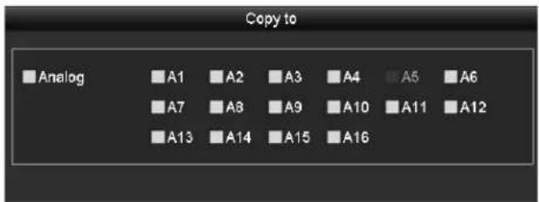
text_image
Copy to Analog A1 A2 A3 A4 A5 A6 A7 A8 A9 A10 A11 A12 A13 A14 A15 A16Figure 72, 'opy 'amera™ettings
- ™et encoding parameters for sub-stream.
1) ™elect the Sub-Stream tab.
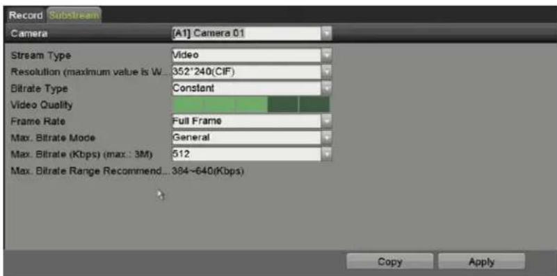
text_image
Record Substream Camera [A1] Camera 0.1 Stream Type Video Resolution (maximum value is W...352'240(CIF) Bitrate Type Constant Video Quality Frame Rate Full Frame Max. Bitrate Mode General Max. Bitrate (Kbps) (max.: 3M) 512 Max. Bitrate Range Recommend...384~640(Kbps) Copy ApplyFigure 73, ^TM ub- ^TM tream Encoding
2) ™elect a camera in the camera drop-down list.
3) 'onfigure the parameters.
4) 'lick √pply to save the settings.
5) (Optional) If the parameters can also be used to other cameras, click Copy to copy the settings to other channels.
NOTE
√ou can select the Video Encoding for the IP sub-stream and analog cameras. For analog cameras, H.264 and H.265 are selectable. For IP cameras supporting H.265, you can select H.265 encoding mode.
5.2 Configuring Recording Schedule
NOTE
The -K series DVRs support continuous, alarm, motion, motion | alarm, motion & alarm, and event triggered recording types.
In this chapter, the record schedule procedure is used as an example; the same procedure can be applied to configure recording schedule.
5.2.1 Set the Record Schedule
^TM et the record schedule to have the camera automatically start/stop recording according to the configured schedule.
- Enter the Record Schedule interface, Menu > Record > ™ schedule. Different recording types are marked in different color icons.
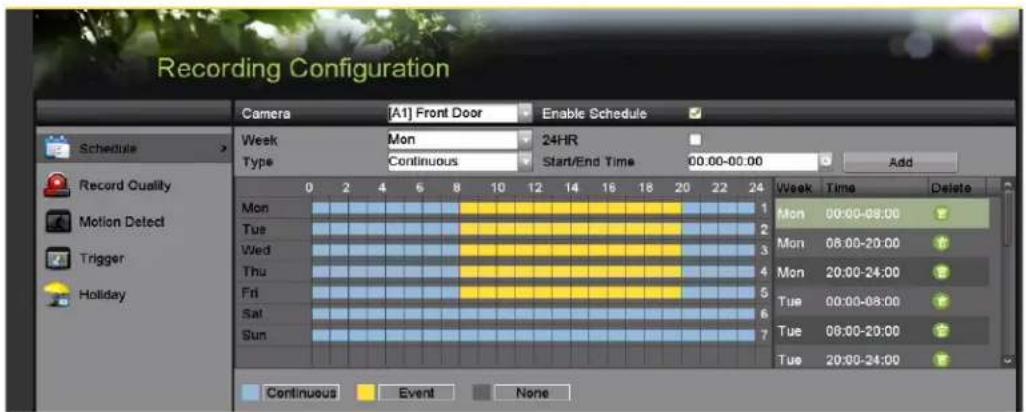
text_image
Recording Configuration Camera [A1] Front Door Enable Schedule Schedule > Week Mon 24HR Type Continuous Start/End Time 00:00-00:00 Add Record Quality Mon 1 Mon 00:00-08:00 Motion Detect Tue 2 Mon 08:00-20:00 Trigger Wed 3 Mon 20:00-24:00 Holiday Thu 4 Mon Fri 5 Tue 00:00-08:00 Sat 6 Tue 08:00-20:00 Sun 7 Tue 20:00-24:00 Continuous Event NoneFigure 74, Record ™ schedule
• Continuous: ™ scheduled recording
• Event: Recording triggered by event triggered alarm
-
'hoose the camera you want to configure in the Camera drop-down list.
-
'heck the E nable Schedule checkbox.
- 'onfigure the record schedule.
5.2.2 Edit the Schedule
- 'lick Edit.
- In the message box, choose the day to which you want to set the schedule.
- To schedule an all-day recording, check the √II Day checkbox.
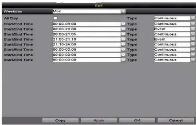
text_image
Edit Weekday Mon All Day Type Continuous Start/End Time 00:00-08:00 Type Continuous Start/End Time 08:00-20:00 Type Event Start/End Time 20:00-21:05 Type Continuous Start/End Time 21:05-21:10 Type Event Start/End Time 21:10-24:00 Type Continuous Start/End Time 00:00-00:00 Type Continuous Start/End Time 00:00-00:00 Type Continuous Start/End Time 00:00-00:00 Type Continuous Copy Apply OK CancelFigure 75, Edit ™ schedule – All Day
- To set non-all day schedules, leave the √II Day checkbox blank and set the ™tart/End times.
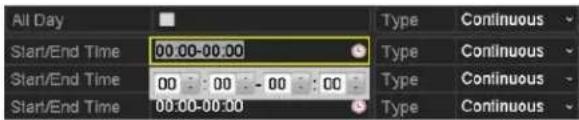
text_image
All Day Start/End Time 00:00-00:00 Start/End Time 00 00 - 00 00 Start/End Time 00:00-00:00 Type Continuous Type Continuous Type Continuous Type ContinuousFigure 76, Edit ™schedule – ™et Time Period
i NOTE
...p to eight periods can be configured for each day. Time periods cannot overlap.
To enable Event, Motion, Alarm, M | A (motion or alarm), and M & A (motion and alarm) triggered recording, you must configure the motion detection settings, alarm input settings, or V'A settings as well.
- Repeat the above steps 1 to 4 to schedule recording for other days in the week. If the schedule can also be set for other days, click Copy.
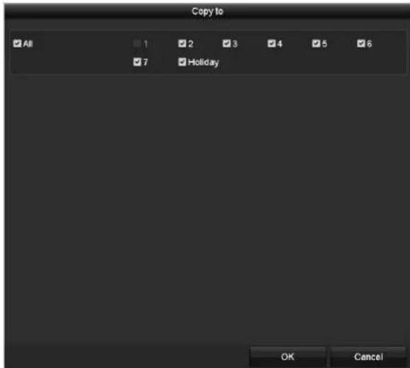
text_image
Copy to All 1 2 3 4 5 6 7 Holiday OK CancelFigure 77, 'opy ^TM schedule to Other Days
i NOTE
The Holiday option is available when you enable holiday schedule in Holiday settings.
- 'lick 'K to save setting and go back to upper level menu.
5.2.3 Draw the schedule
- 'lick on the color icon to select a record type in t he event list on the right-side of the interface.
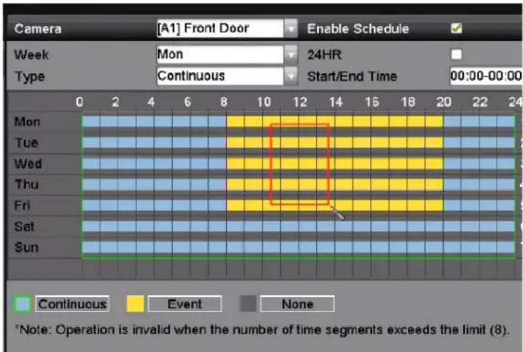
text_image
Camera [A1] Front Door Enable Schedule Week Mon 24HR Type Continuous Start/End Time 00:00-00:00 Mon Tue Wed Thu Fri Sat Sun Continuous Event None *Note: Operation is invalid when the number of time segments exceeds the limit (8).Figure 78, Draw the Recording ™schedule
- Drag the mouse on the schedule.
-
'lick on the other area except for the schedule table to finish and exit from the drawing.
-
√ou can repeat step 3 to set schedule for other channels. If the settings can also be used for other channels, click Copy, and then choose the channel to which you want to copy to.
- 'lick √pply in the "ecord Schedule interface to save the settings."
5.3 Configuring Motion Detection "ecording
Follow the steps to set the motion detection parameters. In •ive -iew mode, once a motion detection event takes place, the D-R can analyze it and perform many actions to handle it. Enabling the motion detection function can trigger specific channels to start recording or trigger full screen monitoring, activate an audio warning, notify the surveillance center, send e-mail, etc.
- Enter the Motion Detection interface, Menu > Recording 'onfiguration > Motion Detect.
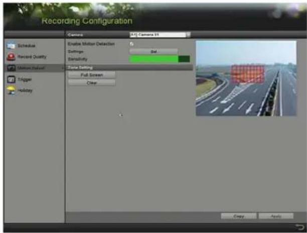
text_image
Recording Configuration Camera A1J Camera 01 Schedule Record Quality Motion Quick Trigger Holiday Enable Motion Detection Settings Set Sensitivity State Setting Full Screen Clear Copy ApplyFigure 7", Motion Detection
- 'onfigure Motion Detection.
a) 'hoose the camera you want to configure.
b) 'heck the Enable Motion Detection checkbox.
c) ...se the mouse to drag and draw the area for motion detection. To set motion detection for the entire area shot by the camera, click Full Screen. To clear the motion detection area, click Clear.
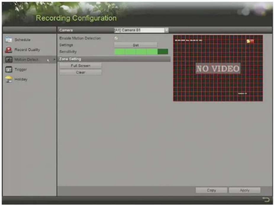
text_image
Recording Configuration Schedule Record Quality Motion Detect Trigger Holiday Camera [A1] Camera 01 Enable Motion Detection Settings Set Sensitivity Zone Setting Full Screen Clear NO VIDEO Copy ApplyFigure 80, Motion Detection – Mask
d) 'lick Set and the channel information message box pops up.
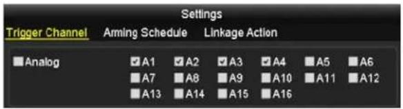
text_image
Settings Trigger Channel Arming Schedule Linkage Action Analog A1 A2 A3 A4 A5 A6 A7 A8 A9 A10 A11 A12 A13 A14 A15 A16Figure 81, Motion Detection ^TM ettings
e) ™elect the channels for which you want the motion detection event to trigger recording.
f) 'lick √pply to save the settings.
g) 'lick 'K to go back to the upper level menu.
h) Exit the Motion Detection menu.
- 'onfigure the schedule (you may choose Motion as the record type).
5.4 Configuring √larm Triggered "ecording and Capture
Follow the procedure to configure alarm triggered recording or capture.
- Enter the √larm Setting interface, Menu > Recording 'onfiguration > Trigger.
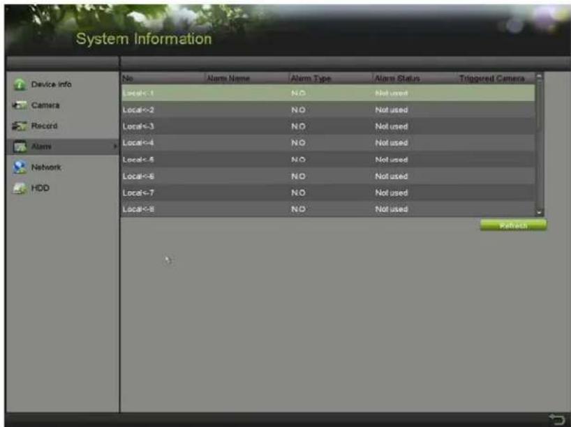
text_image
System Information Device info Camera Record Alarm Network HDD No Alarm Name Alarm Type Alarm Status Triggered Camera Local<-1 N.O. Local<-2 N.O. Local<-3 N.O. Local<-4 N.O. Local<-5 N.O. Local<-6 N.O. Local<-7 N.O. Local<-8 N.O. Local Status Not used Local Status Not used Local Status Not used Local Status Not used Local Status Not used Local Status Not used Local Status Not used Local Status Not used Local Status Not used Local Status Not used Local Status Not used Local Status Not used Local Status Not used Local Status Not used Local Status Not used Local Status Not used Local Status Not used Local Status No. Not used Local Status No. Not used Local Status No. Not used Local Status No. Not used Local Status No. Not used Local Status No. Not used Local Status No. Not used Local Status No. Not used Local Status No. Not used Local Status No. Not used Local Status No. Not used Local Status No. Not used Local Status No. Not used Local States No. Not used Local States No. Not used Local States No. Not used Local States No. Not used Local States No. Not used Local States No. Not used Local States No. Not used Local States No. Not used Local States No. Not used Local States No. Not used Local States No. Not used Local States No. Not used Local States No. No. Not used Local States No. No. Not used Local States No. No. Not used Local States No. No. Not used Local States No. No. Not used Local States No. No. Not used Local States No. No. Not used Local States No. No. Not used Local States No. No. Not used Local States No. No. Not used Local States No. Yes. Local States No. Local States No. Local States No. Local States No. Local States No. Local States No. Local States No. Local States No. Local States No. Local States No. Local States No. Local States No. Local States No. Local States No. Local States No. Local States No. Local States No. Local States No. Local States No. Local States No. Local States Yes. Local States Yes. Local States Yes. Local States Yes. Local States Yes. Local States Yes. Local States Yes. Local States Yes. Local States Yes. Local States Yes. Local States Yes. Local States Yes. Local States Yes. Local States Yes. Local States Yes. Local States Yes. Local States Yes. Local States Yes. Local States Yes. Local States Yes. Local States No. Local States No. Local States No. Local States No. Local States No. Local States No. Local States No. Local States No. Local States No. Local States No. Local States No. Local States No. Local States No. Local States No. Local States No. Local States No. Local States No. Local States No. Local States No. Local States 0% LocationFigure 82, Alarm ™ettings
- 'lick √larm Input tab.
- ™elect Alarm Input No.
- Enter the Alarm Name.
- ™elect ™'. (normally open) or ™.C. (normally closed) for alarm type.
- 'heck the Enable checkbox to enable alarm.
- 'lick Set after Settings to set the triggered channels, arming schedule, linkage actions and PTZ linking.

text_image
Settings Trigger Channel Arming Schedule Linkage Action Analog A1 A2 A3 A4 A5 A6 A7 A8 IP Camera D1 D2 Apply OK CancelFigure 83, Alarm Handling
- 'lick √pply to save the settings.
“. Repeat steps 1 to 8 to configure other alarm input parameters.
- If the settings can also be applied to other alarm inputs, click Copy and choose the alarm input number.
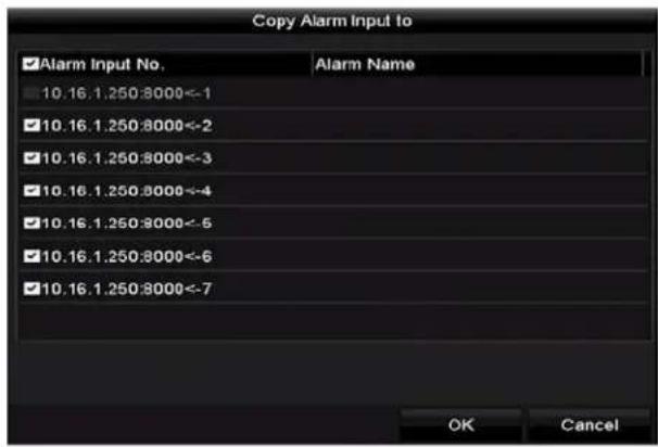
text_image
Copy Alarm Input to ✓Alarm Input No. Alarm Name 10.16.1.250:8000<-1 10.16.1.250:8000<-2 10.16.1.250:8000<-3 10.16.1.250:8000<-4 10.16.1.250:8000<-5 10.16.1.250:8000<-6 10.16.1.250:8000<-7 OK CancelFigure 84, 'opy Alarm Input
5.5 Configuring Event "ecording
The event triggered recording can be configured through the menu. Events include motion detection, alarm, and -'A events (face detection/face capture, line crossing detection, intrusion detection, region entrance detection, region exiting detection, loitering detection, people gathering detection, fast moving detection, parking detection, unattended baggage detection, object removal detection, audio loss exception detection, sudden change of sound intensity detection, and defocus detection).

NOTE
D™-72xxH...I-Kx ™eries D-Rs support -'A (line crossing detection and intrusion detection) of all channels. 'hannels with audio support audio exception detection.
D^TM-7216H ≤ I-Kx^TM eries D-Rs support 2-ch -'A (line crossing detection and intrusion detection). 'hannels with audio support audio exception detection.
For analog channels, line crossing detection and intrusion detection conflict with other –'A detection such as sudden scene change detection, face detection, and vehicle detection. Only one function can be enabled.
- Enter the -'A settings interface and select a camera for the -'A settings, Menu > 'amera > -'A.
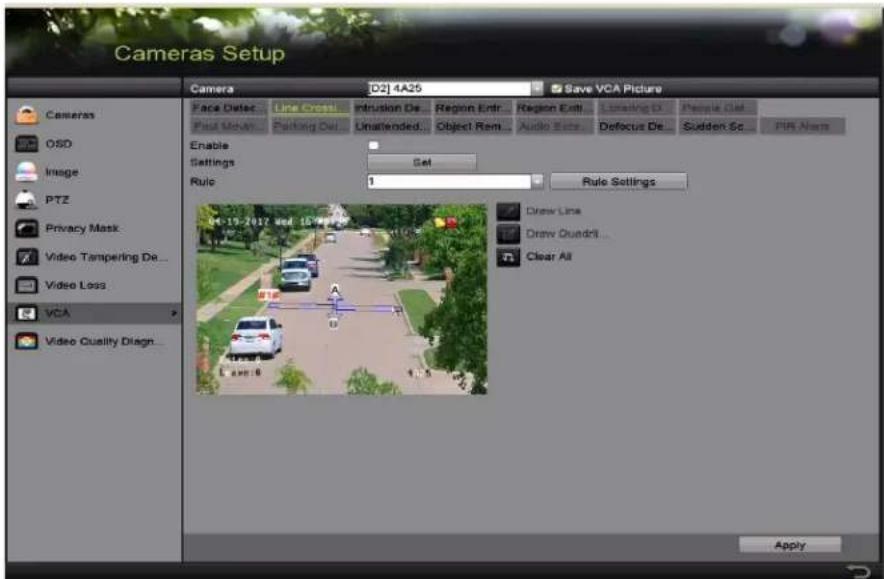
text_image
Cameras Setup Camera D2] 4A25 Save VCA Picture Face Detect Line Cross Intrusion De... Region Entr... Region Exit... Lighting D People Set Post Move Parking Out Unattended... Object Rent... Audio Eats Defocus De... Sudden Sc... PIN Alarm Enable Settings Set Rule 1 Rule Settings Draw Line Draw Quadri... Clear All 04-19-2027 Wed 15:00:00 Video Tampering De... Video Loss... VCA Video Quality Diagn... ApplyFigure 85, -'A™ettings
- 'onfigure the detection rules for –'A events. ™ee step 6 in 'chapter 10.3 •ine 'rossing Detection
- 'lick Set to configure the alarm linkage actions for the -'A events.
- 'lick the Trigger Channel tab and select one or more channels to record when the –'A alarm is triggered.
- 'lick √pply to save the settings.
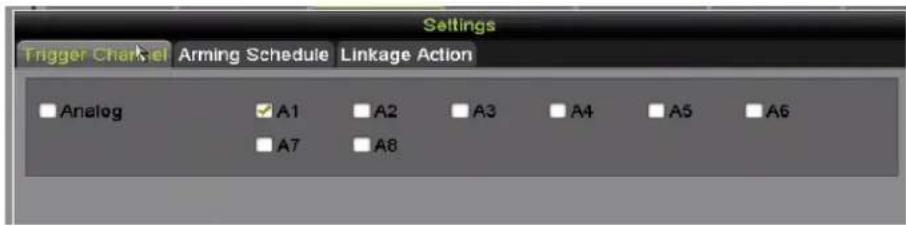
text_image
Settings Trigger Channel Arming Schedule Linkage Action Analog A1 A2 A3 A4 A5 A6 A7 A8Figure 86, ™et Triggered 'amera of –'A Alarm
- Enter "ecord Schedule Settings" interface (Menu > Record > ™chedule > Record ™schedule), and then set Event as the record type.
5.6 Configuring Manual "ecording
Follow these steps to set manual recording parameters. Manual recording is prior to scheduled recording.
- Enter the Manual "ecord interface, Menu > Manual."
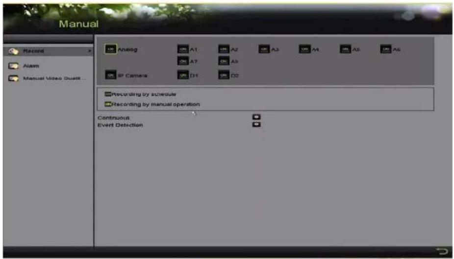
text_image
Manual Record Alarm Manual Video Quality... Analog A1 A2 A3 A4 A5 A6 IP Camera D1 D2 Recording by schedule Recording by manual operation Continuous Event DetectionFigure 87, Manual Record
- Enable manual record.
a) 'lick before the camera number to change it to .
b) Or click the √nalog
status icon to enable manual record of all channels.


- Disable manual record.
a. 'lick to change it to .
b. Or click the √nalog or status icon to disable manual record of all channels.

After rebooting, all enabled manual records are canceled.
5.7 Configuring Holiday "ecording
Follow these steps to configure the record or capture schedule on holidays for that year. √ou may want to have different plans for recording on holidays.
- Enter the Record setting interface, Menu > Recording 'onfiguration.
- 'hoose H oliday on the left bar.
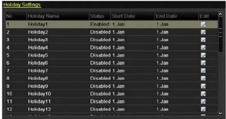
text_image
Holiday Settings No. Holiday Name Status Start Date End Date Edit 1 Holiday1 Enabled 1.Jan 1.Jan 2 Holiday2 Disabled 1.Jan 1.Jan 3 Holiday3 Disabled 1.Jan 1.Jan 4 Holiday4 Disabled 1.Jan 1.Jan 5 Holiday5 Disabled 1.Jan 1.Jan 6 Holiday6 Disabled 1.Jan 1.Jan 7 Holiday7 Disabled 1.Jan 1.Jan 8 Holiday8 Disabled 1.Jan 1.Jan 9 Holiday9 Disabled 1.Jan 1.Jan 10 Holiday10 Disabled 1.Jan 1.Jan 11 Holiday11 Disabled 1.Jan 1.Jan 12 Holiday12 Disabled 1.Jan 1.JanFigure 88, Holiday ^TM ettings
- Enable Edit Holiday schedule.
- 'lick to enter the Edit interface.

text_image
Edit Holiday Name Enable Mode Start Date End Date Holiday5 By Month Jan 1 Jan 1 Apply OK CancelFigure 8", Edit Holiday™ettings
-
'heck the Enable checkbox
-
™elect Mode from the drop-down list.
There are three different modes for the date format to configure holiday schedule. By Month, By Week, and By Date are selectable.
-
™et the start and end dates.
-
'lick √ pply to save settings.
". 'lick 'K to exit the Edit interface.
- 'onfigure the record schedule.
'hoose Holiday in the ™ schedule drop-down list or draw the schedule on the Holiday timeline.
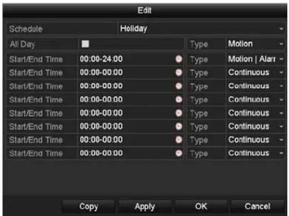
text_image
Edit Schedule Holiday All Day Type Motion Start/End Time 00:00-24:00 Type Motion | Alar Start/End Time 00:00-00:00 Type Continuous Start/End Time 00:00-00:00 Type Continuous Start/End Time 00:00-00:00 Type Continuous Start/End Time 00:00-00:00 Type Continuous Start/End Time 00:00-00:00 Type Continuous Start/End Time 00:00+00:00 Type Continuous Start/End Time 00:00-00:00 Type Continuous Copy Apply OK CancelFigure "0, EditTM schedule – Holiday
i NOTE
...p to eight periods can be configured for each day. Time periods cannot overlap each other.
In the channel time table, both holiday schedule and normal day schedule are displayed.
Repeat step 4 above to set Holiday schedule for other channels. If the holiday schedule can also be used for other channels, click Copy and choose the channel you want to apply the settings.
5.8 Configuring "edundant"ecording
Enabling redundant recording, which saves the record files not only in the R/W HDD but also in the redundant HDD, will effectively enhance data safety and reliability.
√you must set the ™torage mode in the HDD advanced settings toGroup before you set the HDD property to Redundant. There should be at least another HDD that is in Read/Write status.
- Enter the HDD Information interface, Menu >TMystem 'onfiguration >HDD.

text_image
Label Capacity Status Property Type Free Space Group Edit Delete 1 931.51GB Normal R/W Local 865GB 1 - 3 931.51GB Normal R/W Local 931GB 1 -Figure "1, HDD General
-
™elect the HDD and click 📋 to enter the •ocal HDD ™ettings interface.
-
™et the HDD property to Redundant.
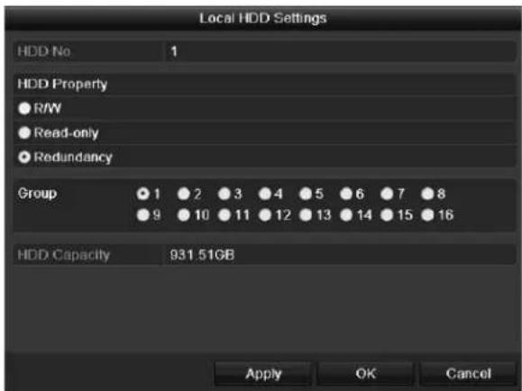
text_image
Local HDD Settings HDD No 1 HDD Property ● R/W ● Read-only ● Redundancy Group ● 1 ● 2 ● 3 ● 4 ● 5 ● 6 ● 7 ● 8 ● 9 ● 10 ● 11 ● 12 ● 13 ● 14 ● 15 ● 16 HDD Capacity 931.51GB Apply OK CancelFigure "2, HDD General – Editing
- 'lick to save the settings.
- 'lick 'K to go back to the upper level menu.
- Enter the Record setting interface, Menu > Record > Parameters.
- ™elect the "ecord tab.
- ™elect the 'amera you want to configure.
". 'lick the More Settings button.
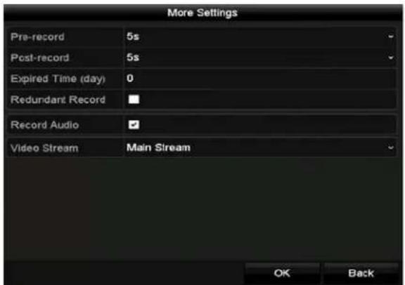
text_image
More Settings Pre-record 5s Post-record 5s Expired Time (day) 0 Redundant Record Record Audio Video Stream Main Stream OK BackFigure "3, More™ettings
- 'heck the "edundant"ecord checkbox.
- 'lick 'K to save the settings.
- If the encoding parameters can also be used to other channels, click Copy and choose the channel to apply the settings to.
5.9 Configuring HDD Group
√ou can group the HDDs and save the record files in specific HDD groups.
- Enter HDD setting interface, Menu >TMystem 'onfiguration >HDD.
- TMelect TMtorage Mode tab.
'heck whether the storage mode of the HDD is Group. If not, set it to Group.
- ™elect General in the left bar.
- 'lick to enter editing interface.
- 'onfiguring HDD group.
- 'hoose a group number for the HDD group.
- 'lick √pply to save your settings.
- 'lick 'K to go back to the upper level menu.
“. Repeat the above steps to configure more HDD groups.
- 'hoose the 'hannels for which you want to save the r record files in the HDD group.
- Enter Storage Mode interface, Menu>HDD>Advanced>™ storage Mode.
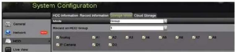
text_image
System Configuration HDD Information Record Information Storage Mode Cloud Storage Mode Group Record on HDD Group 1 Analog A1 A2 A3 A4 A5 A6 A7 A8 P Camera D1 D2Figure "4, HDD Advanced
- 'hoose Group number in the drop-down list of "ecord on HDD Group
- 'heck the channels you want to save in this group.
- 'lick √pply to save settings.

After configuring the HDD groups, configure the recording settings.
5.0 Files -rotection
- lock the recorded files or set the HDD property to Read Only to protect the files from being overwritten.
5.0. -rotect File by Locking the "ecord Files
- Enter Export Settings interface, Menu > File Management.
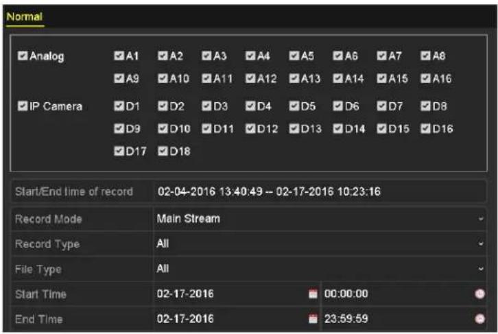
text_image
Normal ✓ Analog ✓ A1 ✓ A2 ✓ A3 ✓ A4 ✓ A5 ✓ A6 ✓ A7 ✓ A8 ✓ A9 ✓ A10 ✓ A11 ✓ A12 ✓ A13 ✓ A14 ✓ A15 ✓ A16 ✓ IP Camera ✓ D1 ✓ D2 ✓ D3 ✓ D4 ✓ D5 ✓ D6 ✓ D7 ✓ D8 ✓ D9 ✓ D10 ✓ D11 ✓ D12 ✓ D13 ✓ D14 ✓ D15 ✓ D16 ✓ D17 ✓ D18 Start/End time of record 02-04-2016 13:40:49 - 02-17-2016 10:23:16 Record Mode Main Stream Record Type All File Type All Start Time 02-17-2016 00:00:00 End Time 02-17-2016 23:59:59Figure "5, Export
- ™elect the channels you want to investigate by checking the checkbox to
- 'onfigure the record mode, record type, file type, start time and end time.
- 'lick S earch to show the results.

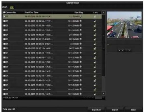
text_image
Search result Chart List Camera No Start/End Time Size Play Lock 01 29-12-2015 16:29:58-10:34... 121.50MB 01 29-12-2015 16:34:56-17:17... 1016.88MB 01 29-12-2015 17:17:24-18:00... 1016.50MB 01 29-12-2015 18:00:31-19:45... 1016.49MB 01 29-12-2015 18:45:28-18:35... 214.99MB 01 29-12-2015 09:32:17-09:25... 801.94MB 01 29-12-2015 09:25:24-09:27... 43.76MB 01 29-12-2015 09:30:12-10:08... 967.23MB 01 29-12-2015 10:06:33-10:45... 1016.33MB 01 29-12-2015 10:46:03-11:23... 1016.53MB 01 29-12-2015 11:23:36-12:00... 1017.30MB 01 29-12-2015 12:00:09-12:45... 1017.12MB 01 29-12-2015 12:36:24-13:12... 1017.07MB 01 29-12-2015 13:12:19-13:49... 1016.88MB 01 29-12-2015 13:46:43-14:25... 1017.29MB 01 29-12-2015 14:25:44-15:02... 1016.53MB 01 29-12-2015 16:02:53-16:38... 1016.77MB 01 29-12-2015 15:35:22-16:15... 1017.30MB Total: 32 P : M Export All Export BackFigure "6, Export – ™earch Result
- Protect the record files.
1) 'lick the •ist tab to display the files in list view.
2) Find the record files you want to protect, and then click the icon which will turn to, indicating that the file is locked.

...completed record files cannot be locked.
3) 'lick to change it to unlock the file and the file is not protected.
5.0.2 -rotect File by Setting HDD -property to "ead-'nly
To edit HDD property, you need to set the storage mode of the HDD to Group.
- Enter HDD setting interface, Menu >TMystem 'onfiguration >HDD.

text_image
Label Capacity Status Property Type Free Space Group Edit Delete 1 931.51GB Normal R/W Local 865GB 1 - 3 931.51GB Normal R/W Local 931GB 1 -Figure "7, HDD General
- 'lick to edit the HDD you want to protect.
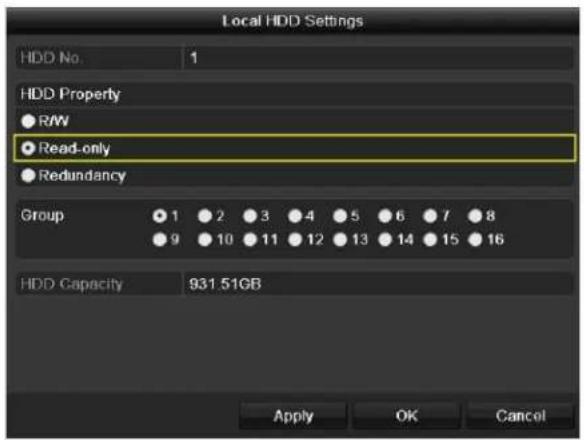
text_image
Local HDD Settings HDD No 1 HDD Property ● R/W ● Read-only ● Redundancy Group 1 2 3 4 5 6 7 8 9 10 11 12 13 14 15 16 HDD Capacity 931.51GB Apply OK CancelFigure "8, HDD General – Editing
- ™et the HDD to Read-only.
- 'lick 'K to save settings and back to the upper level menu.
i NOTE
√ou cannot save any files in a Read-only HDD. If you want to save files in the HDD, change the property to R/W.
If there is only one HDD and is set to Read-only, the DVR cannot record any files. Only live view mode is available.
If you set the HDD to Read-only when the DVR is saving files in it, then the file will be saved in next R/W HDD. If there is only one HDD, the recording will be stopped.
5. •• 'ne-Key Enabling and Disabling H.264+/H.265+ for √nalog Cameras
For -K series DVRs, you can one-key enable or disable H.264+/H.265+ for the analog cameras.
5.•• • 'ne-Key Enabling H.264+/H.265+ √II √nalog Cameras
- Enter the "ecord menu, Menu > Record."
- 'lick to enter the Advanced™ettings interface.
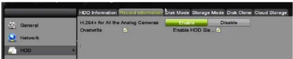
text_image
HDD Information Record Information Disk Mode Storage Mode Disk Clone Cloud Storage H.264+ for All the Analog Cameras Enable Disable Overwrite Enable HDD Sie...Figure "", Advanced ™ettings
- 'lick Enable to enable H.264+/H.265+ for all the analog cameras and the following attention box pops up.
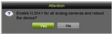
text_image
Attention Enable H.264+ for all analog cameras and reboot the device? Yes NoFigure 100, Attention Box
- 'lick Yes to enable the function and reboot the device to have new settings taken effect.
5.2 'ne-Key Disabling H.264+/H.265+ √II √nalog Cameras
- Enter the "ecord menu, Menu > Record."
-
'lick to enter the advanced interface.
-
'lick Disable to disable H.264+ for all the analog cameras and the following attention box pops up.
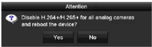
text_image
Attention Disable H.264+/H.265+ for all analog cameras and reboot the device? Yes NoFigure 101, Attention Box
- 'lick Yes to enable the function and reboot the device to have new settings taken effect.
5.2 Configuring •080p Lite
When 1080p •ite Mode is enabled, 1080p •ite (real-time) encoding resolution is supported. If not, up to 1080p (non-real-time) is supported.

This chapter is applicable to D ^TM -72xxH ≤ I-Kx ^TM eries D-Rs.
5.2. Enabling •080p Lite Mode
-
Enter the "ecord menu, Menu > Record."
-
'lick √ dvanced to enter the advanced interface.
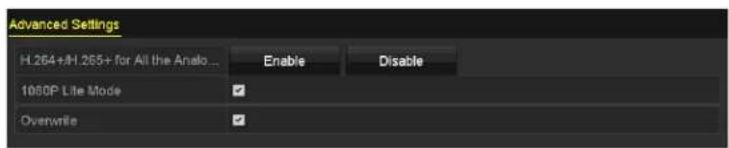
text_image
Advanced Settings H.264+H.265+ for All the Anelo... Enable Disable 1060P Lite Mode OverwriteFigure 102, Advanced Interface
- 'heck the •080–Lite Mode checkbox and click √pply to pop up the attention box. After enabling 1080p •ite Mode, the 3 MP signal is not accessible by analog channels.
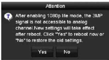
text_image
Attention After enabling 1080p lite mode, the 3MP signal is not accessible to analog channel. New settings will take effect after reboot. Click "Yes" to reboot now or "No" to restore the old settings. Yes NoFigure 103, Attention
- 'lick Yes to reboot the device to have new settings taken effect.
5.2.2 Disabling the •080p Lite Mode
-
Enter the "ecord menu, Menu > Record."
-
'lick to enter the advanced interface.
-
...ncheck the •080p Lite Mode checkbox and click √pply. The following attention box pops up.
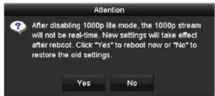
text_image
Attention After disabling 1080p lite mode, the 1080p stream will not be real-time. New settings will take effect after reboot. Click "Yes" to reboot now or "No" to restore the old settings. Yes NoFigure 104, Attention
- 'lick Yes to reboot the device to activate the new settings or TMo to restore the old settings.
Chapter 6 -layback
Play back the recorded video files of a specific channel in Live View mode. Channel switch is supported.
6.··· Instant -layback by Channel
Choose a channel in live view mode and click the quick setting toolbar.

In instant playback mode, only record files recorded during the last five minutes on this channel will be played back.
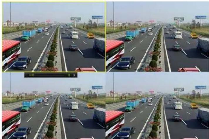
natural_image
Four-panel composite image showing a multi-lane highway with traffic and vehicles, no visible text or symbols.Figure 105, Instant Playback Interface
6.••.2 -laying Back by ™ormal Search
- layback by Channel
- Enter the -layback interface.
- Right click a channel in live view mode and select – layback from the menu, as shown in the following figure:
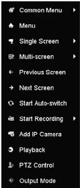
text_image
Common Menu Menu Single Screen Multi-screen Previous Screen Next Screen Start Auto-switch Start Recording Add IP Camera Playback PTZ Control Output ModeFigure 106, Right-click Menu ...nder Live View
- layback by Time
Play back video files recorded in specified time duration. Multi-channel simultaneous playback and channel switch are supported.
-
Enter - layback interface, Menu > Playback.
-
Check the checkbox of channel(s) in the channel list and then double-click to select a date on the calendar.
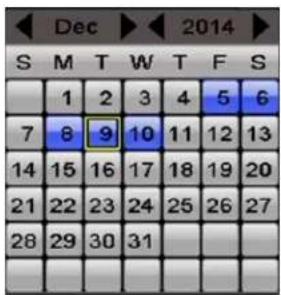
text_image
Dec 2014 S M T W T F S 1 2 3 4 5 6 7 8 9 10 11 12 13 14 15 16 17 18 19 20 21 22 23 24 25 26 27 28 29 30 31 _______________________________Figure 107, Playback Calendar
i NOTE
If there are record files for that camera on that day, the calendar icon for that day is displayed as 9. Otherwise, it is displayed as .9
- layback Interface
^TM elect the main stream or sub-stream from the drop-down playback list.
√ou can also use the toolbar in the bottom of the -layback interface to control playing progress, as shown in the following figure.
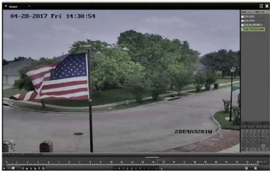
text_image
04-28-2017 Fri 14:30:54 ZDE163201WFigure 108, Playback Interface
^TM elect the channel(s) if you want to switch playback to another channel or execute simultaneous playback of multiple channels.
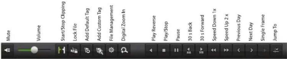
text_image
Mute Volume Start/Stop Clipping Lock File Add Default Tag Add Custom Tag File Management Digital Zoom In Play Reverse Play/Stop Pause 30 s Back 30 s Forward Speed Down 1 x Speed Up 2 x Previous Day Next Day Single Frame Jump ToFigure 10", Playback Toolbar
Table 1-8 Detailed Explanation of Playback Toolbar
| Button | Operation | Button | Operation | Button | Operation |
| Audio on/Mute | ^TM tart/ ^TM to| clipping | •ock File | |||
| Add default tag | Add customized tag | File management for video clips, locked files and tags | |||
| Reverse play/Pause | ^TM top | Digital Zoom | |||
| 30s forward | 30s reverse | Pause/Play | |||
| Fast forward | Previous day | ^TM low forward | |||
| Full ^TM creei | Exit | Next day | |||
| ^TM ave the clips | Process bar | ^TM caling up/down the time line |

NOTE
The 01 of care 01 of 2015 14 07 2015 16:10:27
end time of the record files.
■ represents normal recording (manual or schedule).
■ represents event recording (motion, alarm, motion | alarm, motion & alarm).
Playback progress bar: use the mouse to click any point of the progress bar to locate special frames.
- laying Back by Event Search
Play back record files on one or several channels searched out by restricting event type (motion detection, alarm input or VCA). Channel switch is supported.
-
Enter the -layback interface, Menu > Playback.
-
Click and Nextlet to enter the Event yback interface.
-
™elect √larm Input, Motion, VC√ as the event type, and specify the start time and end time for search.
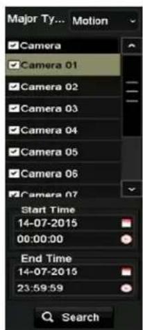
text_image
Major Ty... Motion Camera Camera 01 Camera 02 Camera 03 Camera 04 Camera 05 Camera 06 Camera 07 Start Time 14-07-2015 00:00:00 End Time 14-07-2015 23:59:59 SearchFigure 110, Video ™earch by Motion Detection
- Click Search, and the record files matching the search conditions will be displayed on a list.
- ™elect and click 📋 button to play back the record files.

NOTE
Click Back to return to the search interface.
If there is only one channel triggered, clicking 📄akes you to the Full-screen – layback interface of this channel.
If several channels are triggered, clicking takes you to the Synchronous -layback interface. 'heck the checkbox to select one channel for playback or select multiple channels for synchronous playback.
The maximum number of channels for synchronous playback supported varies by model.
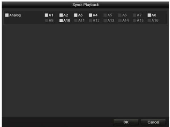
text_image
Synch Playback Analog A1 A2 A3 A4 A5 A6 A7 A8 A9 A10 A11 A12 A13 A14 A15 A16 OK CancelFigure 111, ™elect 'hannels for ™ynchronous Playback ????????
- On the Event -layback interface, select main stream or sub-stream from the drop-down playback list.

NOTE
...se the toolbar in the bottom of the -layback interface to control the playing process.
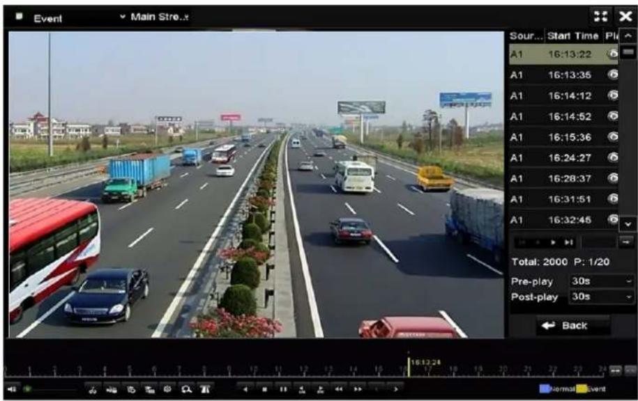
text_image
Event Main Street... Sour... Start Time Pl A1 16:13:22 A1 16:13:35 A1 16:14:12 A1 16:14:52 A1 16:15:36 A1 16:24:27 A1 16:28:37 A1 16:31:51 A1 16:32:45 Total: 2000 P: 1/20 Pre-play 30s Post-play 30s BackFigure 112, Playback by Event Interface
Pre-play and post-play can be configured for playing back event triggered record files.
-re-play: The time to play back before the event. For example, if an alarm triggered the recording at 10:00, if the pre-play time is 5 seconds, the video will start play back at 9:59:55.
-ost-play: The time to play back after the event. For example, if an alarm triggered recording ends at 11:00, if the post-play time is 5 seconds, the video plays until 11:00:05.
- Click ☑ or ☑ to select the previous or next event. Refer to Table 6-1 for the description of buttons on the toolbar.
- laying Back by Tag
Video tag allows you to record related information such as people and location of a certain time point during playback. √ou can also use video tag(s) to search for record files and position the time point.
- Enter Playback interface, Menu > Playback.
- TMearch and play back record file(s).
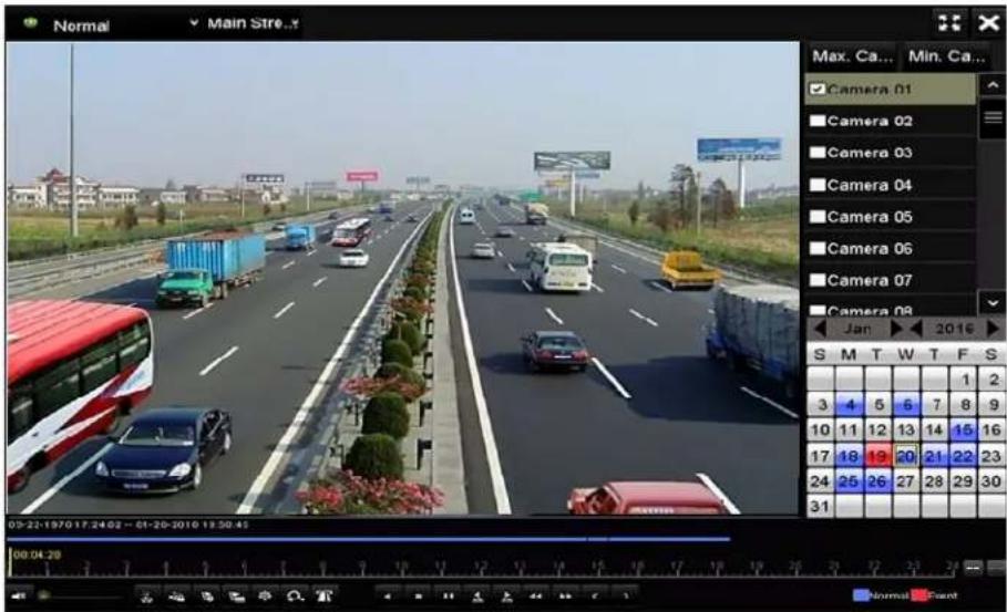
text_image
Normal Main Stre... Max. Ca... Min. Ca... Camera 01 Camera 02 Camera 03 Camera 04 Camera 05 Camera 06 Camera 07 Camera 08 Jan 2016 S M T W T F S 1 2 3 4 5 6 7 8 9 10 11 12 13 14 15 16 17 18 19 20 21 22 23 24 25 26 27 28 29 30 31 05:22-1970 17:24:02 - 01-20-2010 13:30:45 00:04:20 Normal CancelFigure 113, Playback by Time Interface
- Click add default tag.
- Click add customized tag and input tag name.
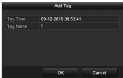
text_image
Add Tag Tag Time 09-12-2015 08:53:41 Tag Name 1 OK CancelFigure 114, Add Tag
i NOTE
A maximum of 64 tags can be added to a single video file.
- Tag Management
- Click the button to check, edit, and delete tag(s).
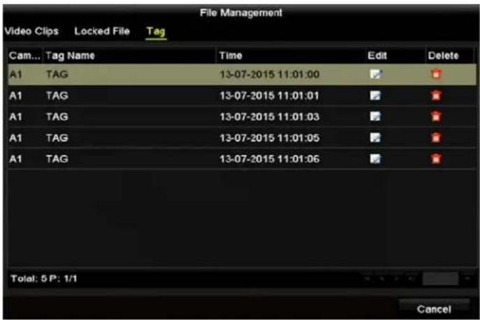
text_image
File Management Video Clips Locked File Tag Cam... Tag Name Time Edit Delete A1 TAG 13-07-2015 11:01:00 A1 TAG 13-07-2015 11:01:01 A1 TAG 13-07-2015 11:01:03 A1 TAG 13-07-2015 11:01:05 A1 TAG 13-07-2015 11:01:06 Total: 5 P: 1/1 CancelFigure 115, Tag Management Interface
- ™elect Tag from the drop-down list in the -layback interface.
- 'hoose channels, edit start time and end time, and then click Search to enter the Search "esult interface.

NOTE
Enter a keyword in the textbox KIwsearch the tag on your command.
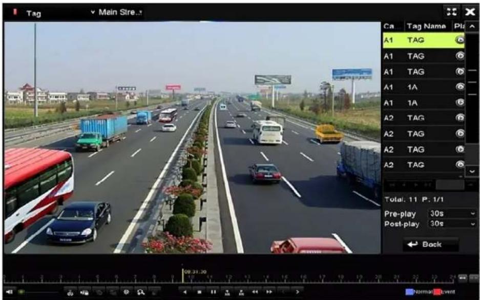
text_image
Tag Main Stre... Ca Tag Name A1 TAG A1 TAG A1 TAG A1 1A A1 1A A2 TAG A2 TAG A2 TAG A2 TAG Total: 11 P. 1/1 Pre-play 30s Post-play 30s BackFigure 116, -ideo ™earch by Tag
- 'lick to play back the file.

NOTE
'an click Back to return to the search interface.
Pre-play and post-play can be configured.
Click ☑ to select the previous or next tag. Refer to Table 6-1 for the description of toolbar buttons.
- laying Back by Smart Search
The ^TM mart Playback function provides an easy way to get through the less effective information. When you select ^TM mart Playback mode, the system will analyze the video containing the motion or VCA information, mark it with a green color, and play it at normal speed while the video without motion will be played at 16-times speed. The smart playback rules and areas are configurable.
To get the smart search result, the corresponding event type must be enabled and configured on the IP camera. Here we take the intrusion detection as an example.
- Log in to the IP camera by the Web browser and enable intrusion detection by checking the checkbox. Enter the motion detection configuration interface by going to Configuration > Advanced Configuration > Events > Intrusion Detection.

text_image
Motion Detection Video Tampering Alarm Input Alarm Output Exception Face Detection Audio Exception Detection Intrusion Detection Defocus Detection Scene Change Detection Enable Intrusion DetectionFigure 117, ™etting Intrusion Detection on IP Camera
- Configure the required intrusion detection parameters, including area, arming schedule, and linkage methods. Refer to the smart IP camera user manual for detailed instructions.
- Enter the Playback interface, Menu > Playback.
- ™elect Smart in the drop-down list on the top-left side.
- ™elect a camera in the camera list.
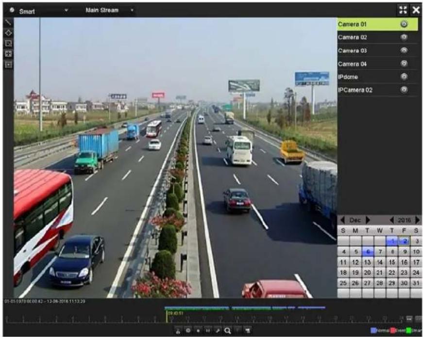
text_image
Smart Main Stream Camera 01 Camera 02 Camera 03 Camera 04 IPdome IPCamera 02 Dec 2016 S M T W T F S 4 5 6 7 8 9 10 11 12 13 14 15 16 17 18 19 20 21 22 23 24 25 26 27 28 29 30 31 01-01-1979 00:00:42 - 12-06-2016 11:13:20 Normal Event Normal EventFigure 118, ™mart Playback Interface
- ™elect a date on the calendar, and click the 📄 button to play.
Table 1-“Detailed Explanation of ™mart Playback Toolbar
| Button | Operation | Button | Operation | Button | Operation |
| Draw line for the line crossing detection | [6BYA] | Draw quadrilateral for the intrusion detection | Draw rectangle for the intrusion detection | ||
| TMet full screen for motion detection |  | 'lear all | TMtart/TMtop clipping | ||
| File management for video clips |  | TMtop playing | Pause playing /Play | ||
| TMmart settings |  | TMearch matched video files | Filter video files by setting the target characters | ||
| TMhow/Hide V'A information |
-
™et the rules and areas for V'A event or motion event smart search.
-
Line Crossing Detection – ™elect , and click on the image to specify the start point and end point of the line.
- Intrusion Detection – 'lick and specify four points to set a quadrilateral region for intrusion detection. Only one region can be set.
- Motion Detection – 'lick and then click and draw the mouse to set the detection area manually. √ou can also click set the full screen as the detection area.
- 'lick to configure the smart settings.
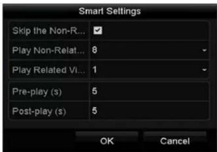
text_image
Smart Settings Skip the Non-R... Play Non-Relat... Play Related Vi... Pre-play (s) Post-play (s) OK CancelFigure 11", TM mart TM ettings
- Skip the ^TM on-Related Video – The non-related video will not be played if this function is enabled.
- Play ^TM on-Related Video at – ^TM et the speed to play the non-related video. Max. 8/4/2/1 are selectable.
- Play Related Video at – ™et the speed to play the related video. Max. 8/4/2/1 are selectable.
i NOTE
Pre-play and post-play is not available for the motion event type.
". 'lick to search and play the matched video files.
- (Optional) 'lick to enter the searched video files by setting the target characters, including the gender and age of the human and whether he/she wears glasses.
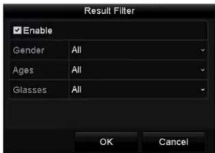
text_image
Result Filter Enable Gender All Ages All Glasses All OK CancelFigure 120, ^TM et Result Filter
i NOTE
The Result Filter function is supported only by IP cameras.
- (Optional) For cameras supporting -'A, click to show the -'A information.

NOTE
The configured line or quadrilateral in VCA configuration and target frame(s) will be shown on the playback interface. Click 📋 hide the VCA information.
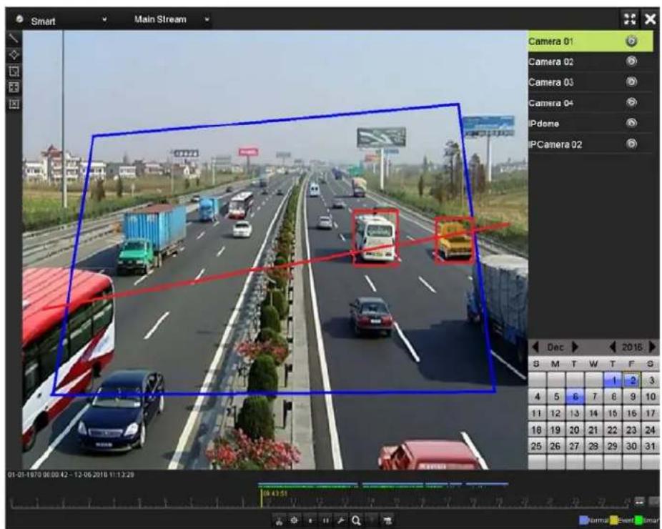
text_image
Smart Main Stream Camera 01 Camera 02 Camera 03 Camera 04 IPdome IPCamera 02 Dec 2016 G M T W T F G 1 2 3 4 5 6 7 8 9 10 11 12 13 14 15 16 17 18 19 20 21 22 23 24 25 26 27 28 29 30 31 01-01-1970 06:00:42 - 12-06-2018 11:13:20 Normal Event SmarFigure 121, ^TM how VCA Information

NOTE
This function is supported by D™-7200H...I-Kx ™eries DVRs.
In ™mart Playback, both analog and IP cameras support VCA information overlay.
If the connected camera does not support VCA, the icon is grey and unavailable.
For analog cameras, the VCA information includes line crossing detection and intrusion detection. For IP cameras, the VCA information includes all the VCA detections of smart IP cameras.
- laying Back by System Logs
Play back record file(s) associated with channels after searching system logs.
- Enter Log Information interface, Menu > Maintenance > Log Information.
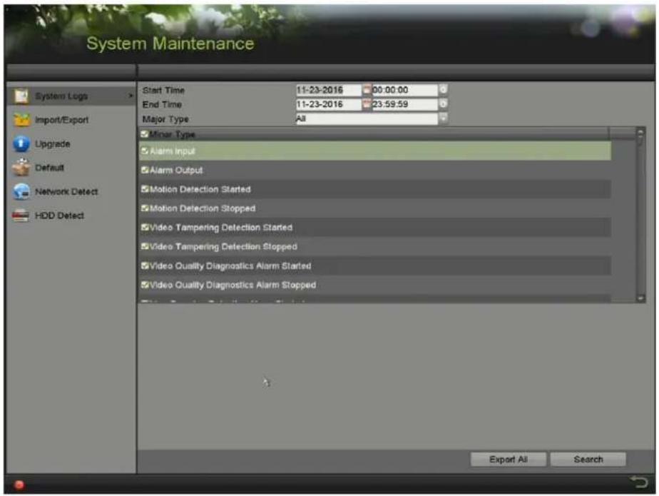
text_image
System Maintenance Start Time 11-23-2016 00:00:00 End Time 11-23-2016 23:59:59 Major Type All Minor Type Alarm Input Alarm Output Motion Detection Started Motion Detection Stopped Video Tampering Detection Started Video Tampering Detection Stopped Video Quality Diagnostics Alarm Started Video Quality Diagnostics Alarm Stopped Export All SearchFigure 122, ™ystem •og ™earch Interface
- 'lick the Log Search tab to enter the System Log Search interface.
- ™et search time and type.
- 'lick the S earch button.
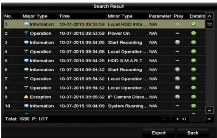
text_image
Search Result No. Major Type Time Minor Type Parameter Play Details 1 Information 10-07-2015 09:53:59 Local HDD Infor... N/A 2 Operation 10-07-2015 09:53:59 Power On N/A 3 Information 10-07-2015 09:54:05 Start Recording N/A 4 Operation 10-07-2015 09:54:08 Local Operation:... N/A 5 Information 10-07-2015 09:54:25 HDD S.M.A.R.T. N/A 6 Information 10-07-2015 09:54:32 Start Recording N/A 7 Operation 10-07-2015 09:54:32 Local Operation:... N/A 8 Operation 10-07-2015 09:54:32 Local Operation:... N/A 9 Exception 10-07-2015 09:55:32 IP Camera Disco... N/A 10 Information 10-07-2015 10:04:09 System Running... N/A Total: 1690 P: 1/17 Export BackFigure 123, Result of ™ystem •og ™earch
- 'hoose a log with record file and click the button to enter the -layback interface.
If there is no record file at the time point of the log, the message box "No result found" will pop up.
- layback Management
...se the toolbar at the bottom of the Playback interface to control the playing process.
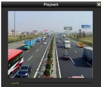
natural_image
Highway scene with multiple vehicles and trucks, no visible text or symbols on the road or traffic.Figure 124, Interface of Playback by Log
- -laying Back by Sub—eriods
The video files can be played in multiple sub-periods simultaneously on the screens.
- Enter -layback interface, Menu > Playback.
- ™elect Sub-periods from the drop-down list in the upper-left corner of the page to enter the Sub-periods – layback interface.
- ™elect a date and start playing the video file.
- ™elect the Split-screen ™umber from the drop-down list. ...p to 16 screens are configurable.
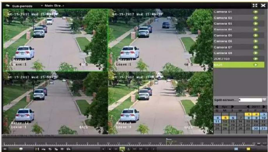
text_image
Sub-periods Main Street... 01-19-2017 Wed 15:46:37 01-19-2017 Wed 15:46:37 Camera 01 Camera 02 Camera 03 Camera 04 Camera 05 Camera 06 Camera 07 Camera 08 20E2103 A25 Split-screen... Apr 2017 S M T W F G 4 5 6 7 8 9 10 11 12 13 14 15 16 17 18 19 20 21 22 23 24 25 26 27 28 29 30 31Figure 125, Interface of ^TM ub-periods Playback

NOTE
According to the defined number of split-screens, the video files on the selected date can be divided into average segments for playback.
E.g., if there are video files existing between 16:00 and 22:00, and the 6-screen display mode is selected, then it can play the video files for 1 hour on each screen simultaneously.
- laying Back External File
Perform the following steps to look up and play back files in the external devices.
- Enter the Playback interface, Menu > Playback.
- ™elect the External File in the drop-down list on the top-left side.

NOTE
The files are listed in the right-side list.
Click to refresh the file list.
- ™elect and click to play it back.
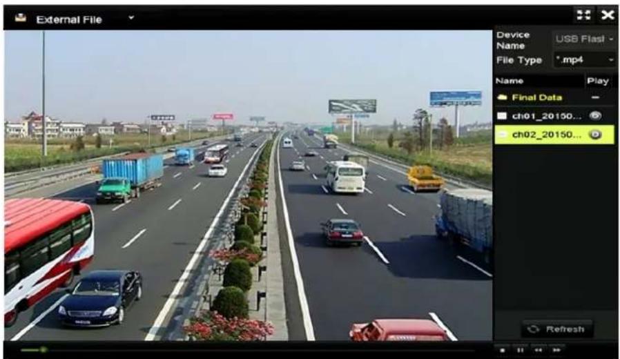
text_image
External File Device USB Flash Name File Type *.mp4 Name Play Final Data ch01_20150... ch02_20150... RefreshFigure 126, Interface of External File Playback
6.2 -layback √uxiliary Functions
6.2.• -laying Back Frame-by-Frame
Play video files frame-by-frame to check image details of the video when abnormal events happen.
-
Go to Playback interface and click until the speed changes to ^TM ing/frame.
-
One click on the playback screen represents playback or adverse playback of one frame. √ou can use ☑ in the toolbar to stop the playing.
6.2.2 Digital Zoom
-
'lick the playback control bar to enter Digital Zoom interface.
-
...se the mouse to draw a red rectangle, and the image within it will be enlarged up to 16 times.

natural_image
Highway scene with vehicles and shipping containers, residential buildings in background (no visible text or symbols)Figure 127, Draw Area for Digital Zoom
- Right click the image to exit the digital zoom interface.
6.2.3 "everse -layback of Multi-Channel
√ou can play back record files of multi-channel reversely. ...p to 16-ch simultaneous reverse playback is supported.
- Enter Playback interface, Menu > Playback.
- 'heck more than one checkbox to select multiple channels, and click to select a date on the calendar.
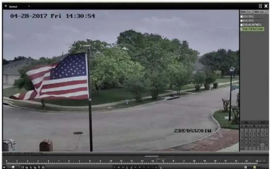
text_image
04-28-2017 Fri 14:30:54 ZDE4A3201W4-ch ™ynchronous Playback Interface
- 'lick to play back the record files reversely.
Chapter 7 Backup
7. • Backing up "ecord Files
Insert the backup device(s) into the device.
7.•• Backing Up by ™ormal Video/–icture Search
The record files or pictures can be backed up to various devices such as ... ^TM B devices (... ^TM B flash drives, ... ^TM B HDDs, ... ^TM B writer).
- Backup Using USB Flash Drives and USB HDDs
- Enter Export interface, Menu > File Management.
-
™elect the type of files to search.
-
Record
-
Event
-
™elect the cameras to search.
-
™et search condition and click Search to enter the search result interface.
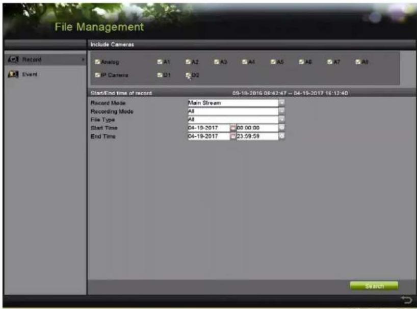
text_image
File Management Include Cameras Record Event Analog A1 A2 A3 A4 A5 A6 A7 A8 IP Camera D1 D2 Start/End time of record 09-18-2016 00:42:47 - 04-19-2017 16:12:40 Record Mode Main Stream Recording Mode All File Type All Start Time 04-19-2017 00:00:00 End Time 04-19-2017 23:59:59 SearchFigure 128, Normal -ideo ™earch for Backup
- The matched video files are displayed in Chart or List display mode.
-
'lick to play the record file if you want to check it.
-
'heck the checkbox next to the video files you want to back up.

NOTE
The size of the selected files is in the lower-left corner of the window.
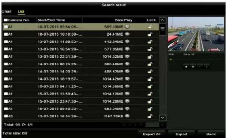
text_image
Search result Chart List Camera No. Start/End Time Size Play Lock A1 10-07-2015 09:54:05-... 589.39MB A1 10-07-2015 16:18:30-... 24.41MB A1 13-07-2015 11:00:53-... 412.54MB A1 13-07-2015 16:54:28-... 577.05MB A1 13-07-2015 22:31:39-... 1014.32MB A1 14-07-2015 08:25:26-... 605.46MB A1 14-07-2015 14:20:28-... 408.62MB A1 14-07-2015 18:19:57-... 1014.42MB A1 15-07-2015 04:11:25-... 1014.36MB A1 15-07-2015 13:39:43-... 1014.12MB A1 15-07-2015 23:47:30-... 1014.20MB A1 16-07-2015 09:40:23-... 663.24MB A3 13-07-2015 16:54:28-... 1567.70KB Total: 99 P: 1/1 Total size: 0B Export All Export BackFigure 12", Result of Normal -ideo TMearch for Backup
- ™elect video files from the Chart or List to export
“. 'lick Export to enter the Export interface.

NOTE
√ou can also click Export √II to select all the video files for backup and enter the Export interface.
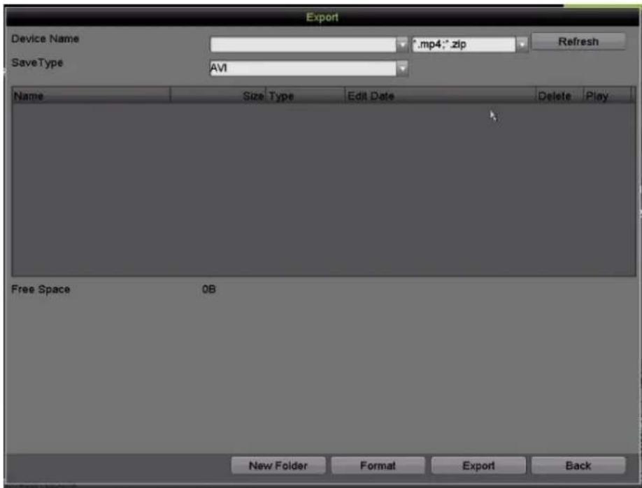
text_image
Export Device Name .mp4;*.zip SaveType AVI Name Size_Type Edit_Date Delete Play Free Space 0B New Folder Format Export BackFigure 130, Export by Normal -ideo ™earch ...sing ... ™B Flash Drive
- ™elect the backup device from the drop-down list (you can also select the file format to filter the files existing in the backup device).
- ™elect the saved file format type.
- 'lick Export on the Export interface to start the backup process.
- On the pop-up message box, click the radio button to export the video files, log, or the player to the backup device.
- 'lick 'K to confirm.
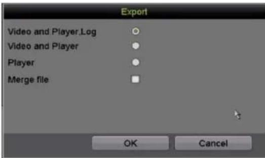
text_image
Export Video and Player.Log Video and Player Player Merge file OK CancelFigure 131, ^TM elect File or Player for Backup
- A prompt message will pop up after the backup process is complete. 'lick 'K to confirm.
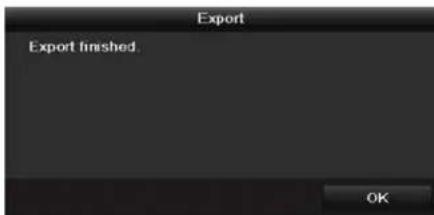
text_image
Export Export finished OKFigure 132, Export Finished

NOTE
Backing up pictures using a ...TMB writer has the same operating instructions. Refer to steps described above.
7.2 Backing Up Video Clips
√ou may also select video clips in playback mode to export directly during Playback, using ... ^TM B devices (... ^TM B flash drives, ... ^TM B HDDs, ... ^TM B writer).
- Enter -layback interface.
- During playback, use 📋 or 📋 in the playback toolbar to start or stop clipping record file(s).
- 'lick to enter the file management interface.
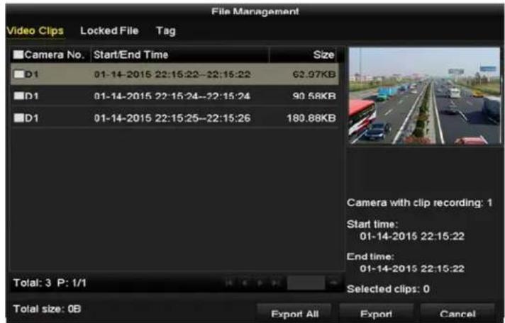
text_image
File Management Video Clips Locked File Tag Camera No. Start/End Time Size D1 01-14-2015 22:15:22-22:15:22 62.97KB D1 01-14-2015 22:15:24-22:15:24 90.58KB D1 01-14-2015 22:15:25-22:15:26 180.88KB Total: 3 P: 1/1 Total size: 0B Export All Export Cancel Camera with clip recording: 1 Start time: 01-14-2015 22:15:22 End time: 01-14-2015 22:15:22 Selected clips: 0Figure 133, -ideo 'lips Export Interface
- Export the video clips in playback. ™ee step 5 of 'hapter 7.1.1Backing ...p by Normal –ideo/Picture ™search for details.
7.2 Managing Backup Devices
7.2. Management of USB Flash Drives, and USB HDDs
- Enter the Export interface.
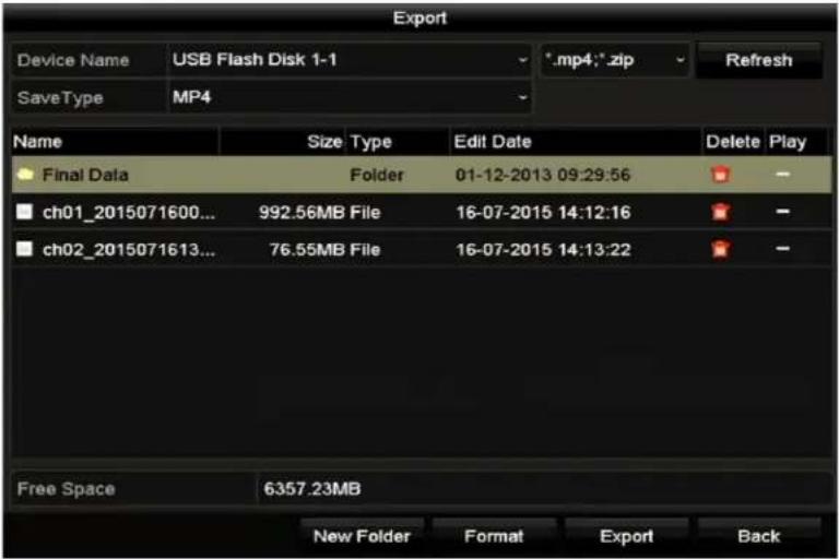
text_image
Export Device Name USB Flash Disk 1-1 *.mp4;*.zip Refresh SaveType MP4 Name Size Type Edit Date Delete Play Final Data Folder 01-12-2013 09:29:56 ch01_2015071600... 992.56MB File 16-07-2015 14:12:16 ch02_2015071613... 76.55MB File 16-07-2015 14:13:22 Free Space 6357.23MB New Folder Format Export BackFigure 134, ™torage Device Management
- Backup device management.
1) 'lick TMew Folder if you want to create a new folder in the backup device.
2) ™elect a record file or folder in the backup device and click if you want to delete it.
3) 'lick Erase if you want to erase the files from a re-writable 'D/D-D.
4) 'lick Format to format the backup device.

If the inserted storage device is not recognized"
- 'lick "efresh.
- Reconnect device.
• 'heck vendor for compatibility.
Chapter 8 √larm Settings
8.• Setting Motion Detection
- Enter Motion Detection interface of 'amera Management, Menu > Recording 'onfiguration > Motion Detect.
- 'hoose a camera for which you want to set up motion detection,
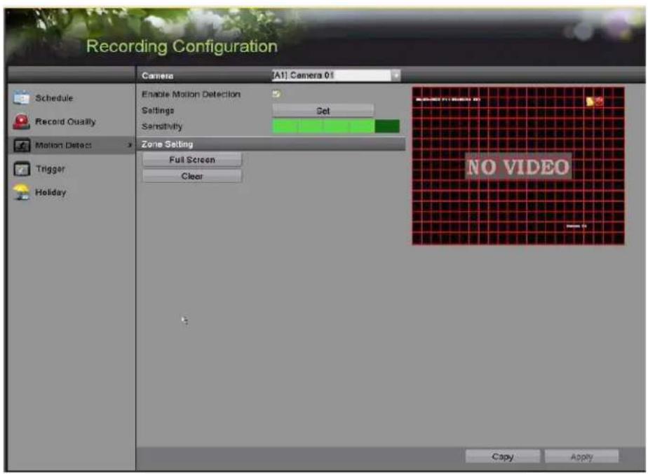
text_image
Recording Configuration Schedule Record Quality Motion Detect Trigger Holiday Camera [Alt] Camera 01 Enable Motion Detection Settings Set Sensitivity Zone Setting Full Screen Clear NO VIDEO Copy ApplyFigure 135, Motion Detection™etup Interface
- ™et detection area and sensitivity.
- 'heck the motion detection checkbox to enable it.
- ...se the mouse to draw detection area(s) or click Full Screen to set the detection area to be the full screen.
- Drag the sensitivity bar to set sensitivity.
- 'lick to set alarm response actions.
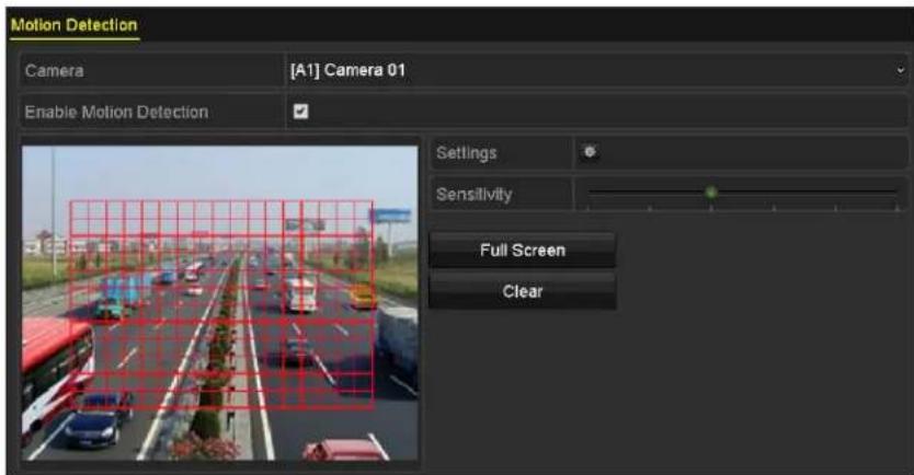
text_image
Motion Detection Camera [A1] Camera 01 Enable Motion Detection Settings Sensitivity Full Screen ClearFigure 136, ^TM et Detection Area and ^TM sensitivity
- Click the Trigger Channel tab and select one or more channels that are to start recording or be displayed full-screen on the monitor when a motion alarm is triggered.
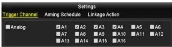
text_image
Settings Trigger Channel Arming Schedule Linkage Action Analog A1 A2 A3 A4 A5 A6 A7 A8 A9 A10 A11 A12 A13 A14 A15 A16Figure 137, ^TM et Trigger Camera of Motion Detection
“. TM et channel arming schedule.
a) ™elect √fming Schedule tab to set the channel's arming schedule.
b) Choose one day of a week and up to eight time periods can be set within each day, or click Copy to copy the time period settings to other day(s).

NOTE
Time periods cannot repeat or overlap.
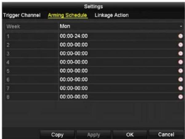
text_image
Settings Trigger Channel Arming Schedule Linkage Action Week Mon 1 00:00-24:00 2 00:00-00:00 3 00:00-00:00 4 00:00-00:00 5 00:00-00:00 6 00:00-00:00 7 00:00-00:00 8 00:00-00:00 Copy Apply OK CancelFigure 138, ^TM et Arming ^TM schedule of Motion Detection
- Click Linkage √ction tab to set up alarm response actions of motion alarm (see Chapter 8.7™etting Alarm Response Actions).
- Repeat the above steps to set up arming schedule for other days of the week.
- Click 'K to complete the channel's motion detection settings.
- To set motion detection for another channel, repeat the above steps or copy the above settings to it.

√ou cannot copy the "Trigger Channel" action.
8.2 Setting Sensor √larms
^TM et up handling method of an external sensor alarm.
- Enter Alarm Input TMettings interface, Menu > Recording Configuration > Trigger.
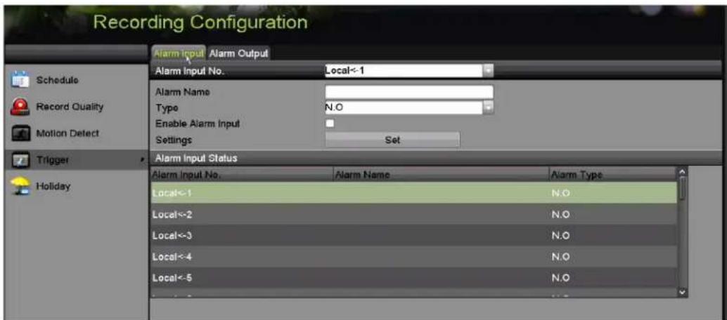
text_image
Recording Configuration Alarm Input Alarm Output Schedule Record Quality Motion Detect Trigger Holiday Alarm Input No. Local<-1 Alarm Name Type N.O Enable Alarm Input Settings Set Alarm Input Status Alarm Input No. Alarm Name Alarm Type Local<-1 N.O Local<-2 N.O Local<-3 N.O Local<-4 N.O Local<-5 N.OFigure 139, Alarm Input ™ettings Interface
- ™et the handling method of the selected alarm input.
- Check the Enable checkbox and click Set to set its alarm response actions.
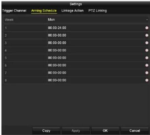
text_image
Settings Trigger Channel Arming Schedule Linkage Action PTZ Linking Week Mon 1 00:00-24:00 2 00:00-00:00 3 00:00-00:00 4 00:00-00:00 5 00:00-00:00 6 00:00-00:00 7 00:00-00:00 8 00:00-00:00 Copy Apply OK CancelFigure 140, ™et Arming ™schedule of Alarm Input
- ™elect the Trigger Channel tab and select one or more channels to record or become full-screen monitoring when an external alarm input is triggered.
- ™elect √rming Schedule tab to set the channel's arming schedule. ™elect one day of a week. Eight time periods maximum can be set each day.

Time periods cannot repeat or overlap.
- ™elect Linkage √ction tab to set up alarm response actions of the alarm input (Refer to Chapter 8.7 ™etting Alarm Response Actions).
- Repeat the above steps to set up arming schedule for other days of the week. √ou can also click on Copy to copy an arming schedule to other days.
- To set another alarm input handling action, repeat the above steps or copy the above settings to it.
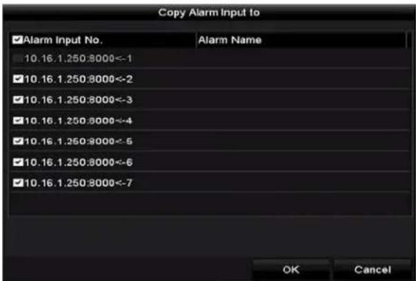
text_image
Copy Alarm Input to ✓Alarm Input No. Alarm Name 10.16.1.250:8000<-1 10.16.1.250:8000<-2 10.16.1.250:8000<-3 10.16.1.250:8000<-4 10.16.1.250:8000<-5 10.16.1.250:8000<-6 10.16.1.250:8000<-7 OK CancelFigure 141, Copy ™ettings of Alarm Input
“. (Optional) Enable one-key disarming for local alarm input 1 (•ocal <- 1).
a) 'heck the Enable One-Key Disarming checkbox.
b) 'lick Settings to enter the linkage action settings interface.
c) ™elect the alarm linkage action(s) you want to disarm for the local alarm input 1. The selected linkage actions include the Full ™creen Monitoring, Audible Warning, Notify ™urveillance 'enter, ™end E-mail, ...pload 'aptured Pictures to 'loud, and Trigger Alarm Output.
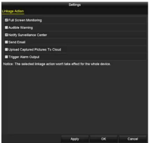
text_image
Settings Linkage Action ✓ Full Screen Monitoring ■ Audible Warning ✓ Notify Surveillance Center ■ Send Email ■ Upload Captured Pictures To Cloud ■ Trigger Alarm Output Notice: The selected linkage action won't take effect for the whole device. Apply OK CancelFigure 142, Disarm •inkage Actions
i NOTE
When the alarm input 1 (•ocal <- 1) is enabled with one-key disarming, the other alarm input settings are not configurable.
8.3 Detecting Video Loss
Detect video loss of a channel and take alarm response action(s).
- Enter Video Loss interface of 'amera Management, Menu> 'amera> -ideo •oss.
- ™elect a channel you want to detect.
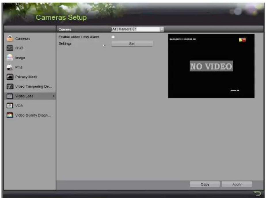
text_image
Cameras Setup Camera [AI] Camera 01 Enable Video Loss Alarm Settings Sel NO VIDEO Video Quality Diagn... Copy ApplyFigure 143, -ideo •oss ™etup Interface
- ™et up video loss handling method.
- 'heck the Enable -ideo •oss Alarm checkbox.
- 'lick S et to set up video loss handling method.
- ™et the channel arming schedule.
a) ™elect Arming ™schedule tab.
b) 'hoose one day of a week and up to eight time periods for each day, or click Copy to copy the time period settings to other day(s).

Time periods cannot repeat or overlap.
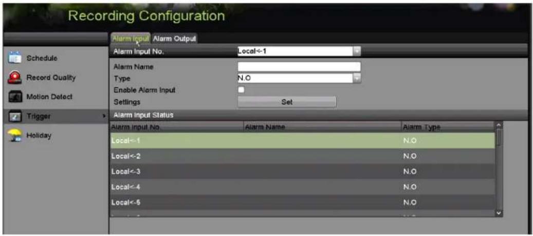
text_image
Recording Configuration Alarm Input Alarm Output Schedule Record Quality Motion Detect Trigger Holiday Alarm Input No. Local<-1 Alarm Name Type N.O Enable Alarm Input Settings Set Alarm Input Status Alarm Input No. Alarm Name Alarm Type Local<-1 N.O Local<-2 N.O Local<-3 N.O Local<-4 N.O Local<-5 N.OFigure 144, ™et Video •oss Arming ™chedule
c) Repeat the above steps to set arming schedule for other days of the week, or click Copy to copy an arming schedule to other days.
- ™elect the Linkage √ction tab to set up video loss alarm response action (refer to Chapter 8.7 ™etting Alarm Response Actions).
- Click 'K to complete the channel's video loss settings.
“. Repeat the above steps to finish setting other channels, or click Copy to copy the above settings to them.
8.4 Detecting Video Tampering
This feature triggers an alarm when the lens is covered and initiates alarm response action(s).
- Enter the Camera Management Video Tampering interface, Menu > Camera > Video Tampering Detection.
- ™elect a channel on which you want to detect video tampering.
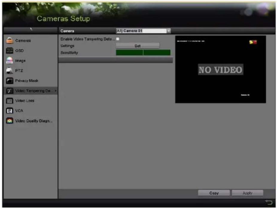
text_image
Cameras Setup Camera [A1] Camera 01 Cameras OSD Image PTZ Privacy Mask Video Tampering De... Video Loss VCA Video Quality Diagn... Enable Video Tampering Dets... Settings Set Sensitivity NO VIDEO Copy ApplyFigure 145, Video Tampering Interface
- Check the Enable Video Tampering Detection checkbox.
- Drag the sensitivity bar and choose a proper sensitivity level.
- Click S et to set the video tampering handling method.
- ™et the channel's arming schedule and alarm response actions.
a) Click Arming ™ schedule tab to set the response action arming schedule.
b) ™elect a day of the week, with up to eight time periods each day.

Time periods cannot repeat or overlap.
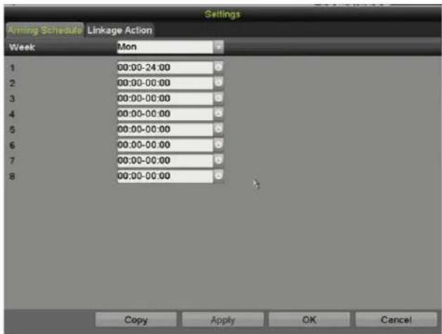
text_image
Settings Arming Schedule Linkage Action Week Mon 1 00:00-24:00 2 00:00-00:00 3 00:00-00:00 4 00:00-00:00 5 00:00-00:00 6 00:00-00:00 7 00:00-00:00 8 00:00-00:00 Copy Apply OK CancelFigure 146, ^TM et –ideo Tampering Arming ^TM schedule
c) ™elect Linkage √ction tab to set alarm response actions of video tampering alarm (refer to 'hapter 8.7™etting Alarm Response Actions).
d) Repeat the above steps to set arming schedule for other days of the week, or use the Copy button to copy an arming schedule to other days.
e) 'lick 'K to complete the video tampering settings of the channel.
- Repeat the above steps to finish settings other channels, or click Copy to copy the above settings to them.
- 'lick √ pply to save and activate the settings.
8.5 Setting √II-day Video "uality Diagnostics
There are two ways to diagnose the video quality" manual and all-day. Perform the following steps to set the threshold of the diagnosing and the linkage actions.
- Enter the 'amera Management Video "uality Diagnostics Settings interface, Menu > 'amera > -ideo ≤uality Diagnostics
- ™elect a channel over which you want to detect video tampering.
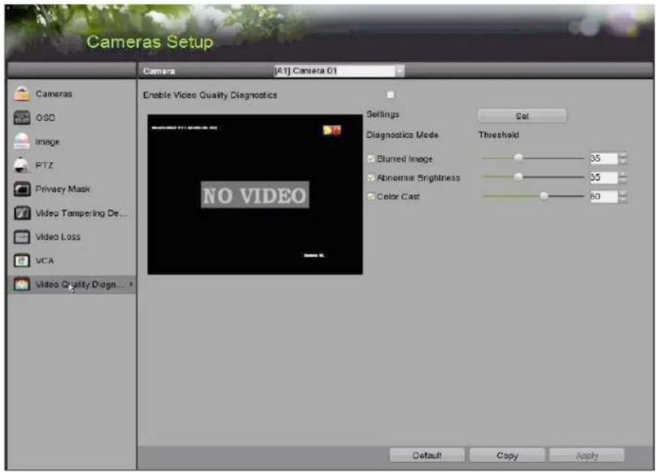
text_image
Cameras Setup Camera [A1] Camera 01 Cameras OSO Image PTZ Privacy Mask Video Tampering De... Video Loss VCA Video Quality Diagn... > Enable Video Quality Diagnostics Settings Set Diagnostics Mode Threshold Blurred Image 35 Abnormal Brightness 35 Color Cast 60 NO VIDEO Default Copy ApplyFigure 147, -ideo ≤ uality Diagnostics Interface
- 'heck the Enable -ideo ≤ uality Diagnostics checkbox.
i NOTE
To enable video quality diagnostics, the function must be supported by the selected camera.
- Enable and set the threshold of the diagnostic types "Blurred Image, √bnormal Brightness, and Color Cast.
- 'heck the corresponding checkbox of the diagnostic type, and adjust the threshold by dragging the bar.
i NOTE
The higher the threshold, the harder it is to detect the exception.
- 'lick Set to set the video quality diagnostics handling method. ™et arming schedule and alarm response actions of the channel.
a) 'lick √rming Schedule tab to set the arming schedule of response action.
b) 'hoose a day of the week and up to eight time periods for each day.
i NOTE
Time periods cannot repeat or overlap.
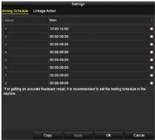
text_image
Settings Aiming Schedule Linkage Action Week Men 1 10:00-16:00 2 00:00-00:00 3 00:00-00:00 4 00:00-00:00 5 00:00-00:00 6 00:00-00:00 7 00:00-00:00 8 00:00-00:00 *For getting an accurate feedback result, it is recommended to set the testing schedule in the daytime. Copy Apply OK CancelFigure 148, ^TM et Arming ^TM schedule of -ideo ≤ uality Diagnostics
c) ™elect Linkage √ction tab to set alarm response actions of video quality diagnostics alarm (refer to 'chapter 8.7™etting Alarm Response Actions).
d) Repeat the above steps to set arming schedule for other days of the week, or click Copy to copy an arming schedule to other days.
e) 'lick OK to complete the video quality diagnostics settings of the channel.
- 'lick to save and activate the settings.
- (Optional) 'opy the same settings to other cameras b y clicking Copy.
8.6 Handling Exceptions
Exception settings refer to the handling method of various exceptions, as noted below"
• HDD Full: The HDD is full
• HDD Error: Writing HDD error, unformatted HDD, etc.
• ™Network Disconnected: Disconnected network cable
• IP Conflicted: Duplicated IP address
- Illegal Login: Incorrect user ID or password
- Input/Recording Resolution Mismatch: The input resolution is smaller than the recording resolution
• Record/Capture Exception: No space for saving recorded files or captured pictures
- Enter E xceptions interface and handle various exceptions, Menu > 'onfiguration > Exceptions.
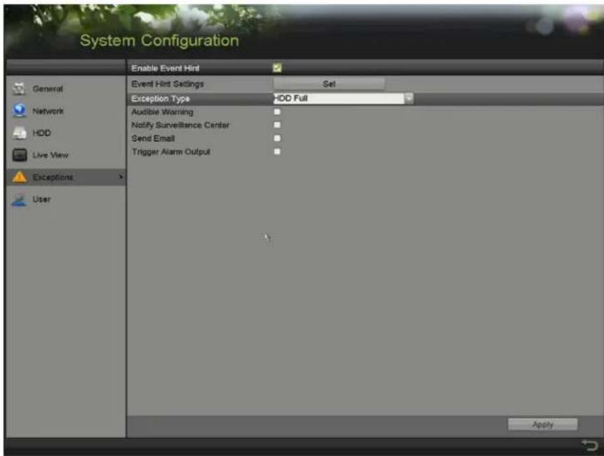
text_image
System Configuration Enable Event Hint Event Hint Settings Set Exception Type HDD Full Audible Warning Notify Surveillance Center Send Email Trigger Alarm Output Apply General Network HDD Live View Exceptions UserFigure 14", Exception ™ettings Interface
- 'heck the Enable Event Hint checkbox to display the event occurs.'lick Set to display the event hint. (Event/Exception icon) when an exception
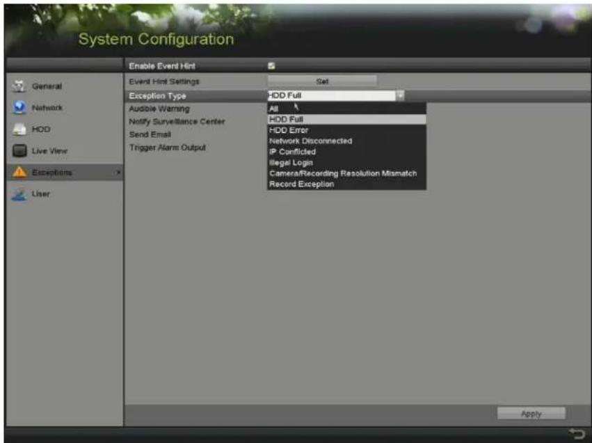
text_image
System Configuration Enable Event Hint Event Hint Settings Set Exception Type HDD Full Audible Warning All Notify Surveillance Center HDD Full Send Email HDD Error Trigger Alarm Output Network Disconnected IP Conflicted Illegal Login Camera/Recording Resolution Mismatch Record Exception User ApplyFigure 150, Event Hint™ettings
NOTE
'lick that appears in •ive -iew to view detailed information about the exception event. 'lick Set to display the event hint.
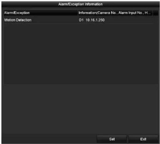
text_image
Alarm/Exception Information Alarm/Exception Information(Camera No., Alarm Input No., H... Motion Detection D1 10.16.1.250 Set ExitFigure 151, Detailed Event
- ™et the alarm linkage actions. For details, see 'hapter 8.7 ™etting Alarm Response Actions.
- 'lick to save the settings.
8.7 Setting √larm Response √ctions
Alarm response actions will be activated when an alarm or exception occurs, including Full ™creen Monitoring, Audible Warning (buzzer), Notify ™urveillance 'enter, ™end E-mail, and Trigger Alarm Output.
• Full Screen Monitoring
When an alarm is triggered, the local monitor (HDMI, -GA, or '-B™ monitor) displays in full screen the video image from the alarming channel configured for full screen monitoring.
If alarms are triggered simultaneously in several channels, their full-screen images will be switched every 10 seconds (default dwell time). A different dwell time can be set in Menu > 'onfiguration > •ive -iew.
Auto-switch will terminate once the alarm stops and you will be taken back to the •ive -iew interface.
- \\udible Warning
Trigger an audible beep when an alarm is detected.
• ™Motify Surveillance Center
^TM ends an exception or alarm signal to the remote alarm host when an event occurs. The alarm host refers to a P' installed with the Remote 'lient.

The alarm signal will be transmitted automatically at detection mode when the remote alarm host is configured.
- Send E-mail
^TM end an e-mail with alarm information to a user or users when an alarm is detected.
- Trigger √larm Output
Trigger an alarm output when an alarm is triggered.
- Enter the Alarm Output interface, Menu > Record 'onfiguration > Trigger > Alarm Output.
- ™elect an alarm output and set the alarm name and dwell time.
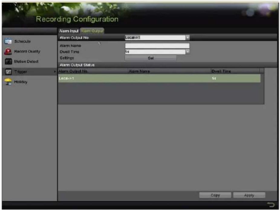
text_image
Recording Configuration Alarm Input Alarm Output Alarm Output No Local=1 Alarm Name Dwell Time 5s Settings Sel Alarm Output Status Alarm Output No. Alarm Name Dwell Time Local=1 5s Holiday Copy ApplyFigure 152, Alarm Output ™ettings Interface
NOTE
If Manually Clear is selected in the Dwell Time drop-down list, it can be cleared only by going to Menu > Manual > Alarm.
- 'lick the Set button to set the alarm output arming schedule.
1) 'hoose a day of the week and set up to eight time periods each day.
i NOTE
Time periods cannot repeat or overlap.
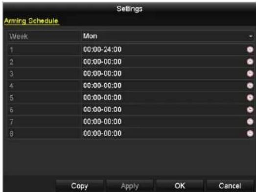
text_image
Settings Aming Schedule Week Mon 1 00:00-24:00 2 00:00-00:00 3 00:00-00:00 4 00:00-00:00 5 00:00-00:00 6 00:00-00:00 7 00:00-00:00 8 00:00-00:00 Copy Apply OK CancelFigure 153, ^TM et Arming ^TM schedule of Alarm Output
2) Repeat the above steps to set arming schedule of other days of the week, or click Copy to copy an arming schedule to other days.
3) 'lick 'K to complete the alarm output arming schedule setting.
4) 'lick √pply to save the settings.
Chapter 9 VC√√larm
√TTETMTI™! ™ome of the features described below require special cameras. Not all features work with all cameras. Please contact your Hikvision ™ales Expert for more information.
The D-R can receive the -'A alarm (line crossing detection, intrusion detection, sudden scene change detection, and audio exception detection) sent by analog cameras. The -'A detection must first be enabled and configured in the camera settings interface. All other -'A detection features must be supported by the connected IP camera.

NOTE
D^TM -72xxH...I-Kx ^TM eries D-Rs support –'A (line crossing detection and intrusion detection) of all channels. 'hannels with audio support audio exception detection.
D^TM-7216H ≤ I-Kx^TM eries support 2-ch -'A (line crossing detection and intrusion detection). 'hannels with audio support audio exception detection.
For the analog channels, line crossing detection and intrusion detection conflict with other –'A detection such as sudden scene change detection, face detection, and vehicle detection. √ou can enable only one function.
9. • Face Detection
The Face Detection function detects faces that appear in the surveillance scene, and specific actions occur when the alarm is triggered.
- Enter the -'A settings interface, Menu > 'amera > -'A.
- ™elect a camera to configure its -'A.
- (Optional) 'heck the Save VC√-icture checkbox to save the pictures captured by -'A detection.
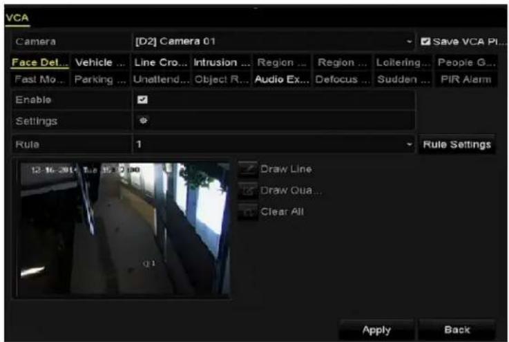
text_image
VCA Camera [D2] Camera 01 Save VCA PL... Face Det... Vehicle ... Line Cro... Intrusion ... Region ... Region ... Loitering ... People G... Past Mo... Parking ... Unattend... Object R... Audio Ex... Defocus ... Sudden ... PIR Alarm Enable Settings Rule 1 Rule Settings Draw Line Draw Oua... Clear All 12-16-3914 Tue 15:00:00 Apply BackFigure 154, Face Detection
- ™et the VCA detection type to Face Detection.
- Click SET to enter the face detection settings interface.
- Configure the trigger channel, arming schedule, linkage action, and PTZ linking for the face detection alarm.
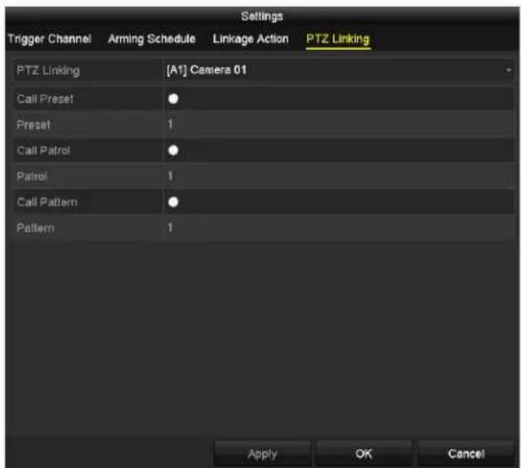
text_image
Settings Trigger Channel Arming Schedule Linkage Action PTZ Linking PTZ Linking [A1] Camera 01 Call Preset Preset 1 Call Patrol Patrol 1 Call Pattern Pattern 1 Apply OK CancelFigure 155, PTZ Linking
- Click the "ule Settings" button to set the face detection rules. Drag slider to set the detection sensitivity.
- Sensitivity: "ange [-5]. The higher the value, the more easily the face can be detected.
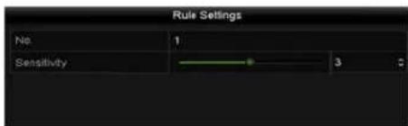
text_image
Rule Settings No 1 Sensitivity 3Figure 156, ™et Face Detection ™ensitivity
- Click to activate the settings.
9.2 Line Crossing Detection
This function can be used for detecting people, vehicles. and objects that cross a set virtual line. The line crossing direction can be set as bidirectional, from left to right, or from right to left. √ou can set the duration for the alarm response actions such as full screen monitoring, audible warning, etc.
- Enter the VCA settings interface, Menu > Camera > VC A.
- ™elect the camera for which to configure the VCA.
- Check the Save VC√-icture checkbox to save the captured VCA detection pictures.
- ™et the VCA detection type to Line Crossing Detection.
- Check the Enable checkbox to enable this function.
- Click 📄 to configure the trigger channel, arming schedule, linkage action, and PTZ linking for the line crossing detection alarm.
- Click the "ule Settings" button to set the line crossing detection rules.
a) ™et the direction to A<->B, A->B, or B->A.
- <-> B: Only the arrow on the B side shows. When an object goes across the configured line, both directions will be detected and alarms will be triggered.
- - B: Only the object crossing the configured line from the A side to the B side will be detected.
- B->√: Only the object crossing the configured line from the B side to the A side will be detected.
b) Drag the slider to set the detection sensitivity.
- Sensitivity: Range [1-100]. The higher the value, the more easily the detection alarm will be triggered.
c) Click 'K to save the rule settings and return to the line crossing detection settings interface.
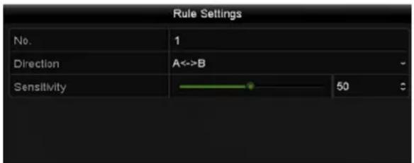
text_image
Rule Settings No. 1 Direction A<->B Sensitivity 50Figure 157, ^TM et Line Crossing Detection Rules
- Click 📋d set two points in the preview window to draw a virtual line.

'lick □ clear the existing virtual line.
...p to four rules can be configured.
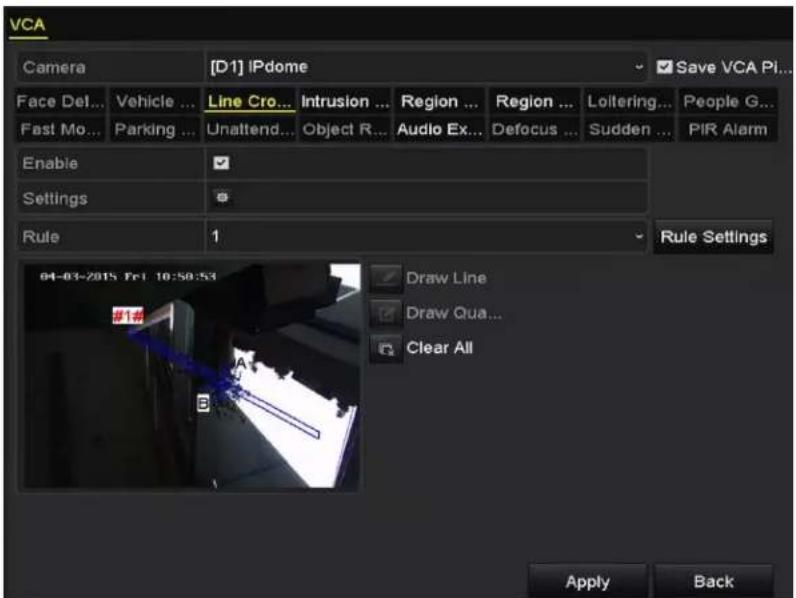
text_image
VCA Camera [D1] IPdome Save VCA Pi... Face Del... Vehicle ... Line Cro... Intrusion ... Region ... Region ... Loitering... People G... Fast Mo... Parking ... Unattend... Object R... Audio Ex... Defocus ... Sudden ... PIR Alarm Enable Settings Rule 1 Rule Settings 04-03-2015 Pre 10:50:53 Draw Line Draw Qua... Clear All Apply BackFigure 158, Draw •ine for •ine 'rossing Detection
". 'lick √pply to activate the settings.

The sudden scene change detection and the line crossing detection cannot be enabled on the same channel.
9.3 Intrusion Detection
The Intrusion Detection function detects people, vehicles, or other objects that enter and loiter in a pre-defined virtual region. ^™ specific actions can be taken when the alarm is triggered.
-
Enter the -'A settings interface, Menu > 'amera > -'A.
-
™elect the camera for which to configure the -'A.
-
'heck the Save VC√-icture checkbox to save the captured -'A detection pictures.
-
™et the -'A detection type to Intrusion Detection.
-
'heck the Enable checkbox to enable this function.
-
'lick to configure the trigger channel, arming schedule, linkage action, and PTZ linking for the intrusion detection alarm.
-
'lick "ule Settings to set the intrusion detection rules."™et the following parameters"
-
Threshold: Range [1s-10s], the threshold for the time the object loiters in the region. When the object in the defined detection area loiters longer than the set time, the alarm will be triggered.
a) Drag the slider to set the detection sensitivity. - Sensitivity: Range [1-100]. This value defines the size of the object that will trigger the alarm. The higher the value, the more easily the detection alarm will be triggered.
- -percentage: Range [1-100]. Percentage defines the ratio of the in-region part of the object that will trigger the alarm. For example, if the percentage is set to 50 percent, when the object enters the region and occupies half of the whole region, the alarm is triggered.
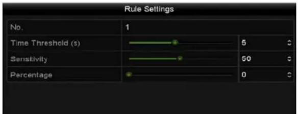
text_image
Rule Settings No. 1 Time Threshold (s) 5 Sensitivity 50 Percentage 0Figure 159, ^TM et Intrusion Crossing Detection Rules
- Click 'K to save the rule settings and back to the line crossing detection settings interface.
- Click ☑ and draw a quadrilateral in the preview window by specifying four vertexes of the detection region, and right click to complete the drawing. Only one region can be configured.

NOTE
Click clear the existing virtual line.
...p to four rules can be configured.
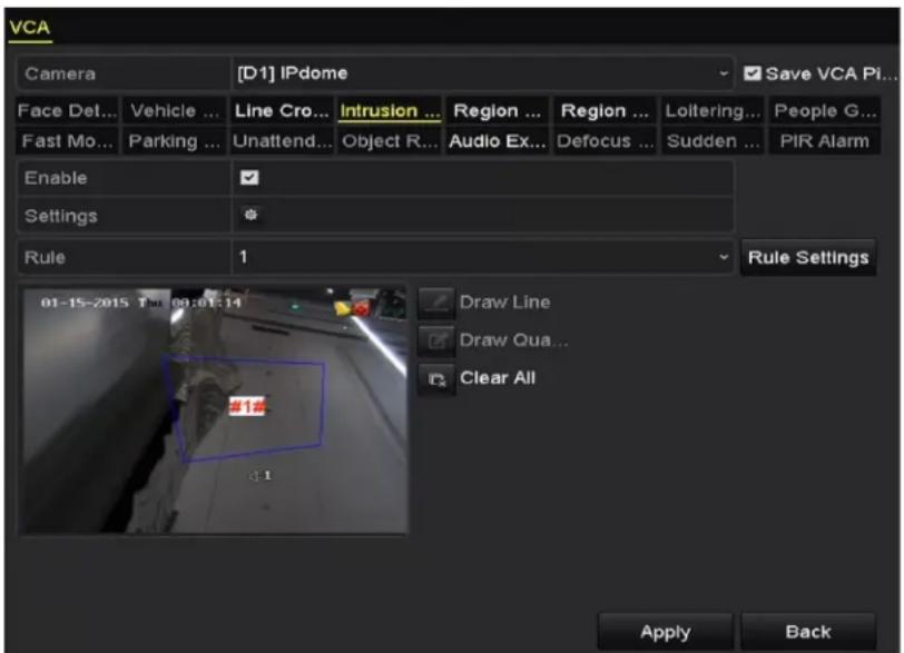
text_image
VCA Camera [D1] iPdome Save VCA Pi... Face Det... Vehicle ... Line Cro... Intrusion ... Region ... Region ... Loitering... People G... Fast Mo... Parking ... Unattend... Object R... Audio Ex... Defocus ... Sudden ... PIR Alarm Enable ✓ Settings § Rule 1 Rule Settings 01-15-2015 T: 00:01:14 Draw Line Draw Oua... Clear All Apply BackFigure 160, Draw Area for Intrusion Detection
- 'lick to save the settings.

NOTE
The sudden scene change detection and the intrusion detection features cannot be enabled on the same channel.
9.4 "egion Entrance Detection
The Region Entrance Detection function detects people, vehicles, or other objects that enter a pre-defined virtual region. ^™ specific actions can be taken when the alarm is triggered.
- Enter the VCA settings interface, Menu > Camera > VCA.
- ™elect the camera for which to configure the VCA.
- Check the Save VC√-icture checkbox to save the captured VCA detection pictures.
- ™et the VCA detection type to "egion Entrance Detection.
- Check the Enable checkbox to enable this function.
- Click 🧑 to configure the trigger channel, arming schedule, linkage action, and PTZ linking for the region entrance detection alarm.
- Click "ule Settings to set the sensitivity of the region entrance detection.
- Sensitivity: "ange [0-•00]. The higher the value, the more easily the detection alarm will trigger.
- Click ☑ and draw a quadrilateral in the preview window by specifying four vertexes of the detection region, and right clicking to complete the drawing. Only one region can be configured.

NOTE
Click ▶ clear the existing virtual line.
...p to four rules can be configured.
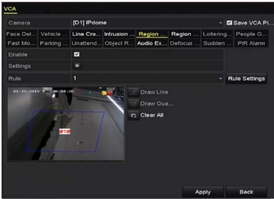
text_image
VCA Camera [D1] IPdome Save VCA Pi... Face Det... Vehicle ... Line Cro... Intrusion ... Region ... Region ... Loitering... People G... Fast Mo... Parking ... Unattend... Object R... Audio Ex... Defocus ... Sudden ... PIR Alarm Enable Settings Rule 1 Rule Settings 01-15-2015 The 00:04:26 Draw Line Draw Qua... Clear All Apply BackFigure 161, ™et Region Entrance Detection
". 'lick √pply to save the settings.
9.5 "egion Exiting Detection
The Region Exiting Detection function detects people, vehicles, or other objects that exit from a pre-defined virtual region. ™ specific actions can be taken when the alarm is triggered.
i NOTE
™ee 'chapter ".5 Region Entrance Detection to configure region exiting detection. ...p to four rules can be configured.
9.6 Loitering Detection
The •oitering Detection function detects people, vehicles, or other objects that loiter in a pre-defined virtual region for a pre-defined time. A series of actions can be taken when the alarm is triggered.
i NOTE
Threshold [1s-10s] in Rule™ettings defines the time the object loiters in the region. If you set the value to 5, an alarm is triggered if the object loiters in the region for 5 seconds. If you set the value to 0, an alarm is triggered immediately once the object enters the region.
...p to four rules can be configured.
9.7 -eople Gathering Detection
The People Gathering Detection alarm is triggered when people gather in a pre-defined virtual region. A series of actions can be taken when the alarm is triggered.
i NOTE
- percentage in Rule ^TM ettings defines the gathering density of the people in the region. If the percentage is small, the alarm is triggered when a small number of people gathers in the defined region.
...p to four rules can be configured.
9.8 Fast Moving Detection
The Fast Moving Detection alarm is triggered when people, vehicles, or other objects move fast in a pre-defined virtual region. A series of actions can be taken when the alarm is triggered.
i NOTE
Sensitivity in Rule™ettings defines the moving speed of the object that will trigger the alarm. The higher the value, the more easily a moving object will trigger the alarm.
...p to four rules can be configured.
9.9 -arking Detection
The Parking Detection function detects illegal parking in places such as highways, one-way streets, etc. A series of actions can be taken when the alarm is triggered.
i NOTE
Threshold [5s-20s] in Rule™ettings defines the time the vehicle parks in the region. If you set the value as 10, an alarm is triggered after the vehicle stays in the region for 10 seconds.
...p to four rules can be configured.
9.0 Unattended Baggage Detection
The ...nattended Baggage Detection function detects objects left in a pre-defined region such as baggage, purses, dangerous materials, etc. A series of actions can be taken when the alarm is triggered.
i NOTE
Threshold [5s-20s] in Rule™ettings defines the time the objects are left in the region. If the value is set to 10, an alarm is triggered after the object stays in the region for 10 seconds. Sensitivity defines similarity of the object to the image's background. If the sensitivity is high, a small object left in the region will trigger the alarm.
...p to four rules can be configured.
9. • 'bject "emoval Detection
Object removal detection function detects the objects removed from the pre-defined region, such as the exhibits on display, and a series of actions can be taken when the alarm is triggered.
i NOTE
Threshold [5s-20s] in Rule™ettings defines the time the objects are removed from the region. If you set the value as 10, an alarm is triggered after the object disappears from the region for 10 seconds.
Sensitivity defines the similarity of the object to the image background. When the sensitivity is high, a very small object taken from the region will trigger the alarm.
...p to four rules can be configured.
9.2 √udio Exception Detection
The Audio Exception Detection function detects abnormal sounds in the surveillance scene such as the sudden increase/decrease of sound intensity. ^TM specific actions can be taken when the alarm is triggered.
i NOTE
Audio Exception Detection is supported on all analog channels.
- Enter the -'A settings interface, Menu > 'amera > -' A.
- ™elect the camera for which to configure the -'A.
- 'heck the Save VC√-icture checkbox to save the captured -'A detection pictures.
- ™et the –'A detection type to √udio Exception Detection.
- 'lick the 📄icon to configure the trigger channel, arming schedule, linkage action, and PTZ linking for the audio exception alarm.
- 'lick "ule Settings to set the audio exception rules.
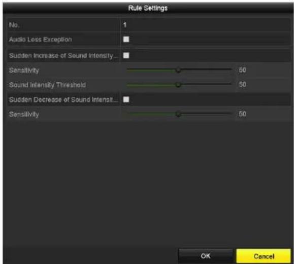
text_image
Rule Settings No. 1 Audio Loss Exception Sudden Increase of Sound Intensity... Sensitivity 50 Sound Intensity Threshold 50 Sudden Decrease of Sound Intensit... Sensitivity 50 OK CancelFigure 162, ^TM et Audio Exception Detection Rules
a) 'heck the √udio Loss Exception checkbox to enable the audio loss detection function.
b) 'heck the Sudden Increase of Sound Intensity Detection checkbox to detect a steep rise in the surveillance scene sound. ™et the sensitivity and threshold for the steep rise in sound.
c) Sensitivity" Range [1-100], the smaller the value, the more severe the change must be to trigger the detection.
d) Sound Intensity Threshold" Range [1-100], this filters the sound in the environment. The louder the environment sound, the higher the value should be. Adjust it according to the environment.
e) 'heck the Sudden Decrease of Sound Intensity Detection checkbox to detect a steep drop in the surveillance scene sound. ^TM et the detection sensitivity [1-100] for the steep drop in sound.
- 'lick to activate the settings.
9.3 Defocus Detection
Image blur caused by defocusing of the lens can be detected. ™ specific actions can be taken when the alarm is triggered.

NOTE
Sensitivity in Rule™ettings ranges from 1 to 100. The higher the value, the more easily the defocus image will trigger the alarm.
9.4 Sudden Scene Change
The ™ene 'hange Detection function detects changes in the surveillance environment by external factors such as the intentional rotation of the camera. ™pecific actions can be taken when the alarm is triggered.

NOTE
Sensitivity in Rule™ ettings ranges from 1 to 100. The higher the value, the more easily the change of scene will trigger the alarm.
For analog cameras, line crossing detection and intrusion detection conflict with other –'A detections such as sudden scene change detection, face detection, and vehicle detection. Only one function can be enabled. If you enable line crossing detection or intrusion detection, if you enable sudden scene change detection and apply the settings, the following attention box pops up to remind you there is not enough resources and asks you to disable the enabled –'A type(s) of the selected channel(s).
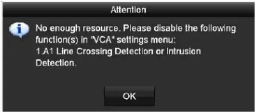
text_image
Attention No enough resource. Please disable the following function(s) in "VCA" settings menu: 1.A1 Line Crossing Detection or Intrusion Detection. OKFigure 163, Disable Other –'A Type(s)
9.5 -l" √larm
A PIR (Passive Infrared) alarm is triggered when an intruder moves within the detector's field of view. The heat energy dissipated by a person, or other warm blooded creatures such as dogs, cats, etc., can be detected.
- Enter the -'A settings interface, Menu > 'amera > -'A.
- ™elect the camera for which to configure the -'A.
- 'heck the Save VC√-icture checkbox to save the captured -'A detection pictures.
- ™et the -'A detection type to -l" √larm.
- 'lick to configure the trigger channel, arming schedule, linkage action, and PTZ linking for the PIR alarm.
- 'lick "ule Settings to set the rules."
- 'lick √pply to activate the settings.
Chapter •0 VC√ Search
With the configured –'A detection, the device supports various –'A search functions" behavior search, face search, plate search, people counting, and heat map results of the IP cameras.
•0.• Face Search
When there are detected face pictures captured and saved in HDD, you can enter the Face Search interface to search the pictures and play the picture related video files according to the specified conditions.
- Enter the Face Search interface, Menu > -'A ™earch > Face ™earch.
- ™elect the camera(s) for the face search.
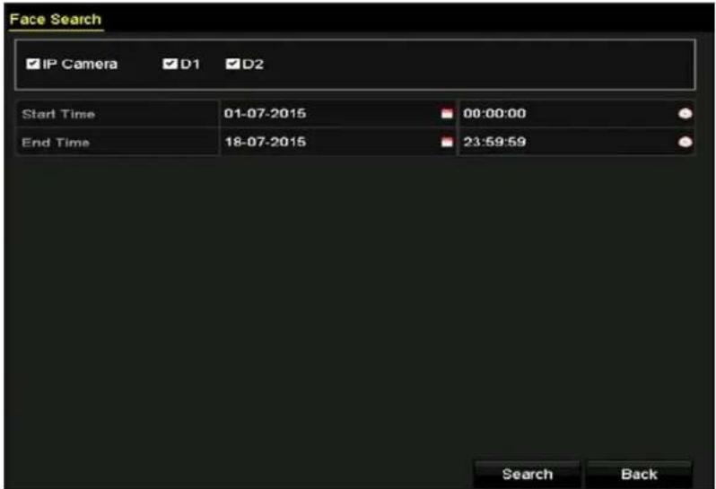
text_image
Face Search IP Camera D1 D2 Start Time 01-07-2015 00:00:00 End Time 18-07-2015 23:59:59 Search BackFigure 164, Face ™earch
- ™pecify the start time and end time for searching the captured face pictures or video files.
- ...pload the pictures from your local storage device for matching the detected face pictures.
- ™et the similarity level for the source pictures and the captured pictures.
- 'lick Search to start searching. The search results of face detection pictures are displayed in list or in chart.
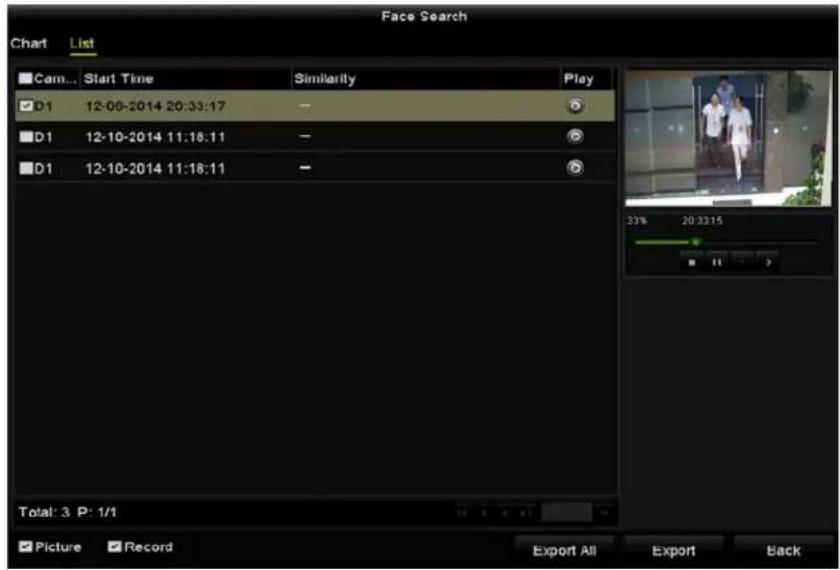
text_image
Face Search Chart List ■Cam... Start Time Similarity Play D1 12:00-2014 20:33:17 D1 12-10-2014 11:18:11 D1 12-10-2014 11:18:11 Total: 3 P: 1/1 Picture Record Export All Export BackFigure 165, Face ™earch Interface
-
Play the face picture related video file.
-
Double click on a face picture to play its related video file in the view window on the top right.
- Or select a picture item and click to play it.
-
Click to stop playing, or click / to play the previous/next file.
-
To export the captured face pictures to a local storage device, connect the storage device and click Export √II to enter the Export interface.
a) Click Export to export all face pictures to the storage device.
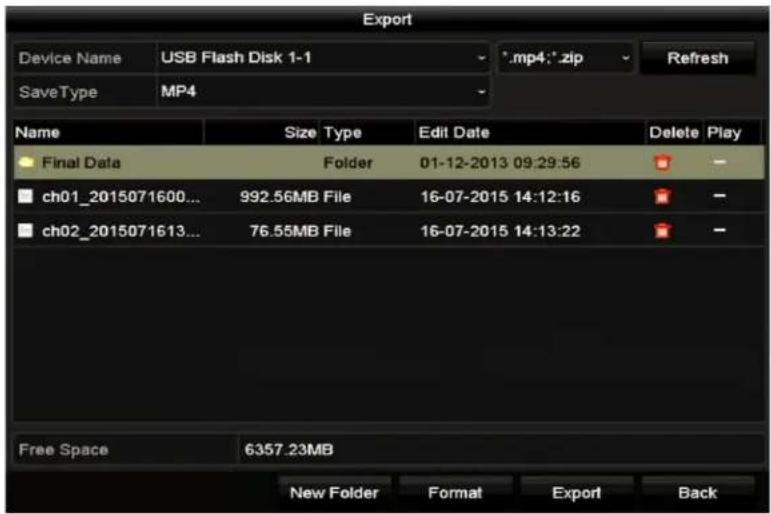
text_image
Export Device Name USB Flash Disk 1-1 *.mp4:*.zip Refresh SaveType MP4 Name Size Type Edit Date Delete Play Final Data Folder 01-12-2013 09:29:56 ch01_2015071600... 992.56MB File 16-07-2015 14:12:16 ch02_2015071613... 76.55MB File 16-07-2015 14:13:22 Free Space 6357.23MB New Folder Format Export BackFigure 166, Export Files
•0.2 Behavior Search
The Behavior Analysis function detects a series of suspicious behavior based on –'A detection. ^TM specific linkage methods will be enabled if the alarm is triggered.
- Enter the Behavior Search interface, Menu > -'A ™earch > Behavior ™earch.
- ™elect the camera(s) for the behavior search.
- ™pecify the start time and end time for searching the matched pictures.
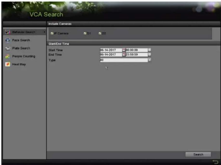
text_image
VCA Search Include Cameras IP Camera D1 D2 Start/End Time Start Time 06-14-2017 00:00:00 End Time 06-14-2017 23:59:59 Type All SearchFigure 167, Behavior ™earch Interface
- ™elect the -'A detection type from the drop-down list, including line crossing detection, intrusion detection, unattended baggage detection, object removal detection, region entrance detection, region exiting detection, parking detection, loitering detection, people gathering detection, and fast moving detection.
- 'lick Search to start searching. The search result pictures are displayed in a list or chart.
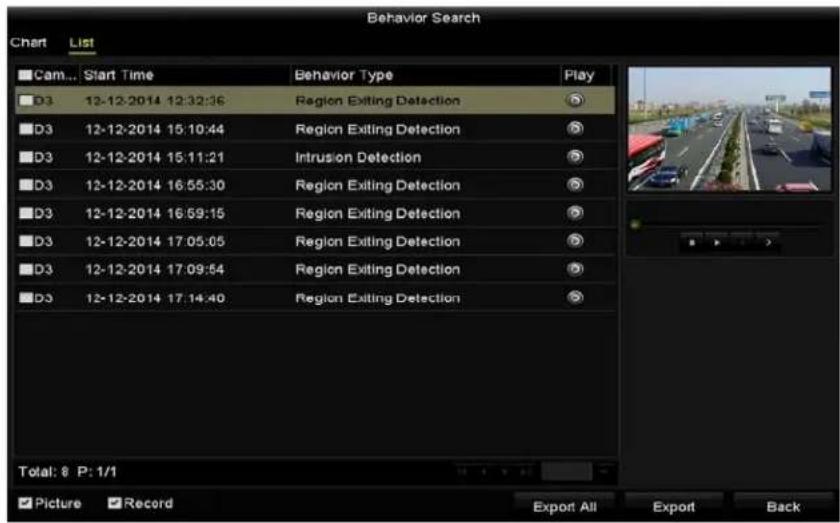
text_image
Behavior Search Chart List Cam... Start Time Behavior Type Play D3 12-12-2014 12:32:36 Region Exiting Detection D3 12-12-2014 15:10:44 Region Exiting Detection D3 12-12-2014 15:11:21 Intrusion Detection D3 12-12-2014 16:55:30 Region Exiting Detection D3 12-12-2014 16:59:15 Region Exiting Detection D3 12-12-2014 17:05:05 Region Exiting Detection D3 12-12-2014 17:09:54 Region Exiting Detection D3 12-12-2014 17:14:40 Region Exiting Detection Total: 8 P: 1/1 Picture Record Export All Export BackFigure 168, Behavior ™earch Results
-
Play the behavior analysis picture related video file.
-
Double click a picture from the list to play its related video file in the view window on the top right.
- Or select a picture item and click to play it.
-
Click to top playing, or click / to play the previous/next file.
-
If you want to export the captured pictures to a local storage device, connect the storage device and click Export √II to enter the Export interface.
- Click E xport to export all pictures to the storage device.
•0.3 -eople Counting
People Counting is used to calculate the number of people who enter or left a pre-defined area and can provide daily/weekly/monthly/annual reports for analysis.
- Enter the -eople Counting interface, Menu > VCA ^TM search > People Counting.
- ™elect the camera for the people counting.
- ™et the report type to Daily Report, Weekly Report, Monthly Report, or Annual Report.
- ™et the statistics time.
- Click Counting to start people counting statistics.
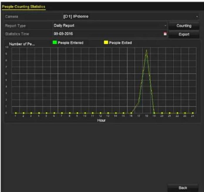
line
| Hour | Number of People Entered | Number of People Exited | |------|--------------------------|-------------------------| | 1 | 0 | 0 | | 2 | 0 | 0 | | 3 | 0 | 0 | | 4 | 0 | 0 | | 5 | 0 | 0 | | 6 | 0 | 0 | | 7 | 0 | 0 | | 8 | 0 | 0 | | 9 | 0 | 0 | | 10 | 0 | 0 | | 11 | 0 | 0 | | 12 | 0 | 0 | | 13 | 0 | 0 | | 14 | 0 | 0 | | 15 | 0 | 0 | | 16 | 0 | 0 | | 17 | 2 | 0 | | 18 | 8 | 0 | | 19 | 0 | 0 | | 20 | 0 | 0 | | 21 | 0 | 0 | | 22 | 0 | 0 | | 23 | 0 | 0 | | 24 | 0 | 0 |Figure 16", People 'ounting Interface
- √ou can click Export to export the statistics report in Excel format.
- 0.4 Heat Map
Heat map is a graphical representation of data represented by colors. The heat map function is usually used to analyze the visit times and dwell time of customers in a configured area.
- Enter the Heat Map interface, Menu > -'A ™earch > Heat Map.
- ™elect the camera for the heat map processing.
- ™et the report type to Daily Report, Weekly Report, Monthly Report, or Annual Report.
- ™et the statistics time.
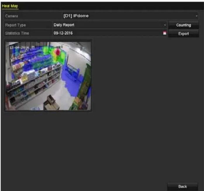
text_image
Heat Map Camera [D1] IPdome Report Type Daily Report Statistics Time 09-12-2016 Counting Export BackFigure 170, Heat Map Interface
- 'lick Counting to export the report data and start heat map statistics. The results are displayed in graphics marked in different colors.
i NOTE
As shown in Figure 10-8, red color block (255, 0, 0) indicates the most popular area, and blue color block (0, 0, 255) indicates the less-popular area.
- √ou can click E xport to export the statistics report in Microsoft Excel format.
Chapter •• ™Network Settings
••• Configuring General Settings
Network settings must be properly configured before you operate the D-R over a network.
- Enter the Network ™ettings interface, Menu > 'onfiguration > Network.
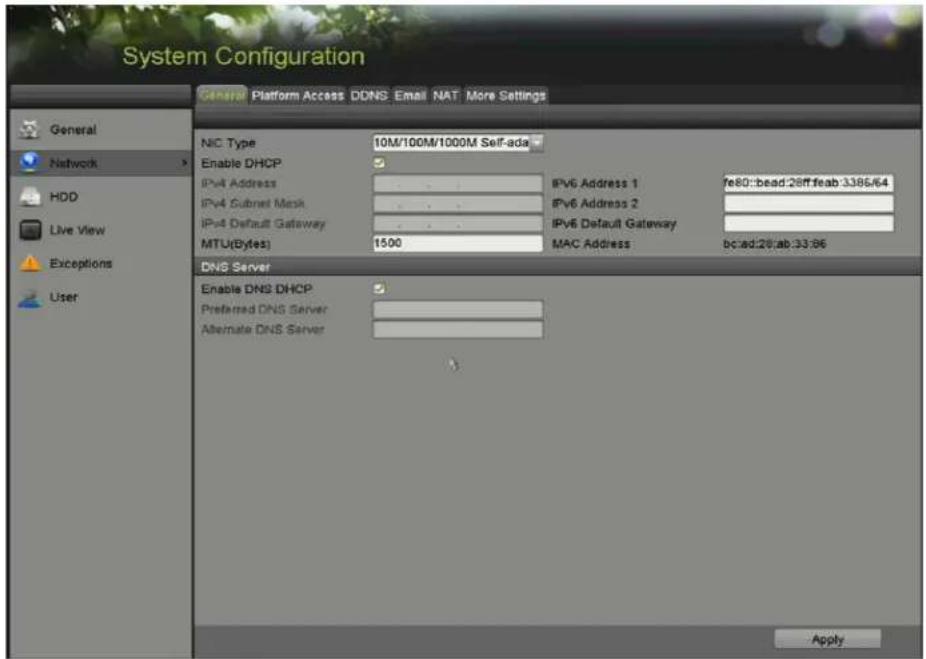
text_image
System Configuration General Platform Access DDNS Email NAT More Settings NIC Type 10M/100M/1000M Self-ada Enable DHCP IPv4 Address IPv4 Subnet Mask IPv4 Default Gateway MTU(Bytes) 1500 IPv6 Address 1 fe80::bead:28ff:feab:3386/64 IPv6 Address 2 IPv6 Default Gateway MAC Address bc:ad:28:ab:33:96 DNS Server Enable DNS DHCP Preferred DNS Server Alternate DNS Server ApplyFigure 171, Network ™ettings Interface
- ™elect the General tab.
- On the General Settings interface, configure the following parameters" NI' Type, IPv4 Address, IPv4 Gateway, MT..., DN™TMerver, and Main NI'.

The valid value of MT... is from 500 to 1500.
If a DH'P server is available, check the Enable DHC—checkbox to obtain an IP address and other network settings from that server automatically.
If DH'P is enabled, you can check the Enable D™S DHC-checkbox or uncheck it and edit the -referred D™S Server and √lternate D™S Server.
- 'lick the √ pply button to save the settings.
••.2 Configuring √dvanced Settings
•.2.• Configuring —oE Settings
The D-R allows access by Point-to-Point Protocol over Ethernet (PPPoE).
- Enter the ™etwork Settings interface, Menu > 'onfiguration > Network.
- ™elect the —oE tab to enter the —oE Settings interface.

text_image
Enable PPPoE User Name PasswordFigure 172, PPPoE ^TM ettings Interface
- 'heck the Enable —oE checkbox to enable this feature.
- Enter User™ame and -assword for PPPoE access.

The ...ser Name and Password are assigned by your I™P.
- 'lick √pply to save the settings.
- After successful settings, the system asks you to re boot the device to enable the new settings, and the PPPoE dial-up is automatically connected after reboot.
- √ou can go to Menu > Maintenance > ™ystem Info > Network interface to view the status of PPPoE connection.
••.2.2 Configuring Hik-Connect
Hik-'onnect provides a mobile phone application and service platform page (www.hik-connect.com) to access and manage the D–R for convenient remote access to the surveillance system.

Hik-'connect can be enabled via ^TM ADP software, the system G...I, and Web browser. We describe the G...I operation steps in this section.
- Enter the ™Network Settings interface, Menu > 'onfiguration > Network.
- ™elect the -latform √ccess tab to enter the Hik-'connect ™ettings interface.
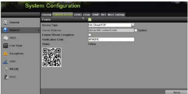
text_image
System Configuration General Pattern Access DDNS Email SNMP NAT More Settings Enable Access Type Disk Cloud P2P Server Address dev@u.bbl-connect.com Custom Enable Stream Encryption Verification Code AFNZHE Status Online ApplyFigure 173, Hik-`onnect™ettings
- 'heck the Enable checkbox to activate the function. The Service Terms interface pops up.
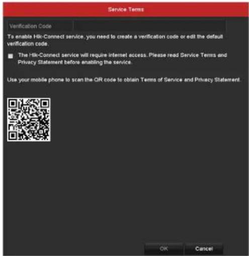
text_image
Service Terms Verification Code To enable Hik-Connect service, you need to create a verification code or edit the default verification code. ■ The Hik-Connect service will require internet access. Please read Service Terms and Privacy Statement before enabling the service. Use your mobile phone to scan the QR code to obtain Terms of Service and Privacy Statement. OK CancelFigure 174, ™ervice Terms
-
'reate the verification code and enter the code in the Verification Code text field.
-
'heck the The Hik-'onnect service will require Internet access. Please read ™ervice Terms and Privacy ™tatement before enabling the service checkbox.
-
™ can the ≤ R code on the interface to read the ™ service Terms and the Privacy ™ statement.
-
'lick 'K to save the settings and return to the Hik-'connect interface.
i NOTE
Hik-'onnect is disabled by default.
The verification code field is empty when the device leaves the factory.
The verification code must contain 6 to 12 letters or numbers and is case sensitive.
If you upgrade an older DVR version with Hik-Connect enabled, Hik-Connect is still enabled. If you disable it and then enable it for the first time, you need to change the verification code if the encrypted verification code is the same as that of the configuration file or the encrypted verification code is empty and the verification code of the configuration file is ABCDEF. In these two conditions, you must create a new verification code or you can delete the default and enter the same verification code as the default one.
Every time you enable Hik-Connect, the ™ervice Terms interface pops up, and you should check the checkbox before enabling it.
- (Optional) Check the C custom checkbox and enter the Server √ddress.
". (Optional) Check the Enable Stream Encryption checkbox. If this feature is enabled, the verification code is required for remote access and live view.

...se your phone's scanning tool to quickly get the device code by scanning the ≤ R code.
- Click √pply to save the settings.
After configuration, you can access and manage the DVR on your mobile phone on which the Hik-Connect application is installed or by the website (www.hik-connect.com).

™ee the help file on the official website (www.hik-connect.com) and the Hik-Connect Mobile Client ...ser Manual for adding the device to Hik-Connect and more operation instructions.
••.2.3 Configuring DD™S
If your DVR is set to use PPPoE as its default network connection, you may set Dynamic DN ^TM (DDN ^TM ) to be used for network access.
Prior registration with your I™P is required before configuring the system to use DDN™.
- Enter the ™Network Settings interface, Menu > Configuration > Network.
- ™elect the DD™S tab to enter the DDNTM ™ettings interface.
- Check the E nable DD™S checkbox to enable this feature.
- ^TM elect DD ^TM S Type. Three different DDN ^TM types are selectable" DynDN ^TM , PeanutHull, and NO-IP.
- DynD™S
a) Enter Server √ddress for DynDN™ (i.e., members.dyndns.org).
b) In the Device Domain ™ame text field, enter the domain obtained from the DynDN™ website.
c) Enter the U ser ™ame and Password registered on the DynDN™ website.
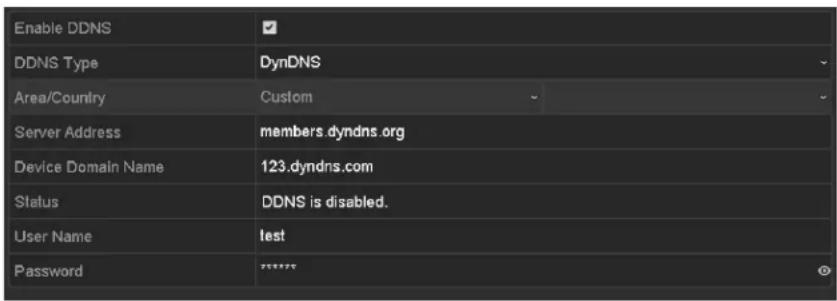
text_image
Enable DDNS DDNS Type DynDNS Area/Country Custom Server Address members.dyndns.org Device Domain Name 123.dyndns.com Status DDNS is disabled. User Name last Password ****Figure 175, DynDN™™ettings Interface
- PeanutHull
a) Enter the ...ser Name and Password obtained from the PeanutHull website.
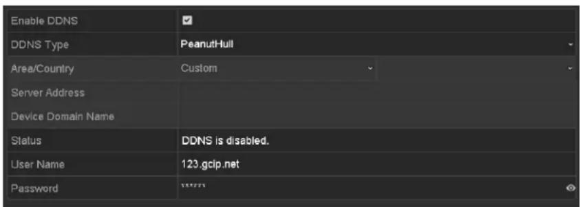
text_image
Enable DDNS DDNS Type Area/Country Server Address Device Domain Name Status User Name Password DDNS is disabled. 123.gcip.netFigure 176, PeanutHull™ettings Interface
• TMO-IP:
a) Enter the account information in the corresponding fields. Refer to the DynDN™ settings.
b) Enter Server √ddress for NO-IP.
c) In the Device Domain ™ame text field, enter the domain obtained from the NO-IP website (www.no-ip.com).
d) Enter the User ™ame and Password registered in the NO-IP website.
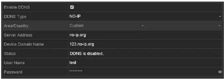
text_image
Enable DDNS DDNS Type NO-IP Area/Country Custom Server Address=no-ip.org Device Domain Name 123.no-ip.org Status DDNS is disabled. User Name Hydrotest PasswordFigure 177, NO-IP ^TM ettings Interface
- 'lick to save and exit the interface.
11.2.4 Configuring ™TP Server
A Network Time Protocol (NTP) ^TM server can be configured on your D–R to ensure the accuracy of system date/time.
-
Enter the ™Network Settings interface, Menu > ™ystem 'onfiguration > General.
-
™elect the ™MTP tab to enter the ™MTP Settings interface.

text_image
Enable NTP Interval (min) 60 NTP Server 210.72.145.44 NTP Port 123Figure 178, NTP ^TM ettings Interface
-
'heck the Enable™TP checkbox to enable this feature.
-
'onfigure the following NTP settings"
-
Interval: Time interval between the two synchronizing actions with NTP server. The unit is minutes.
• ™MTP Server: IP address of NTP server
• ™MTP Port: Port of NTP server -
'lick to save and exit the interface.

The time synchronization interval can be set from 1 to 10080 minutes (default is 60 minutes). If the D-R is connected to a public network, use a NTP server that has a time synchronization function such as the server at the National Time 'enter (IP Address" 210.72.145.44). If the D-R is set in a more customized network, NTP software can be used to establish an NTP server used for time synchronization.
11.2.5 Configuring N√T
Universal Plug and Play (UPnP™) lets the device seamlessly discover the presence of other network devices on the network and establish functional network services for data sharing, communications, etc. Use the UPnP™ function to quickly connect the device to the WAN via a router without port mapping.
- Before Starting
To enable the UPnP™ function, enable the device router's UPnP™ function. When the device network working mode is set to multi-address, the Default Route of the device must be in the same network segment as that of the LAN IP address of the router.
-
Enter the Network Settings interface, Menu > Configuration > Network.
-
Select the N√T tab to enter the UPnP™ Settings interface.
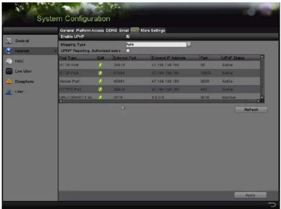
text_image
System Configuration General Platform Access DDNS Email NAT More Settings Enable UPnP Mapping Type Auto UPNP Reporting Authorized users ... Port Type Edit External Port External IP Address Port UPnP Status HTTP Port 36618 47,188,130,109 80 Active RTSP Port 47454 47,194,130,109 10554 Active Server Port 45601 47,184,130,109 8000 Active HTTPS Port 36614 47,184,130,109 443 Active HIG-CONNECT AC 9818 0.0.0 8010 Inactive Refresh ApplyFigure 179, UPnP™ Settings Interface
-
Check Enable UPnP checkbox to enable UPnP ^TM .
-
Set the Mapping Type to Manual or Auto in the drop-down list.
- OPTION 1:
If you select √uto, the Port Mapping items are read-only, and the external ports are set by the router automatically.
1) Click √pply button to save the settings.
2) √ou can click Refresh button to get the latest status of the port mapping.
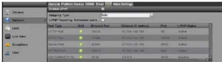
text_image
General Platform Access: DONE Email Enable UHP Mapping Type Auto UPNP Reporting Authorized users Port Type Edit External Port External IP Address Part UPnP Status HTTP Port 30518 47,104,130,109 60 Active MUSB Port 57496 27,104,130,109 10552 Active Server Port 45501 47,104,130,109 8009 Active HTTP Port 28414 27,104,130,109 443 Active HIS-OCCIDENT Ac 9018 88.0.0 9010 ActiveFigure 180, UPnP™ Settings Finished – Auto
- OPTIO™ 2: Manual
If you select Manual as the mapping type, you can edit the external port on demand by clicking to activate the External Port Settings dialog box.
1) Click ☑ to activate the External Port Settings dialog box. Configure the external port No. for server port, http port and RTSP port respectively.
NOTE
√ou can use the default port No. or change it according to actual requirements.
External Port indicates the port No. for the router's port mapping.
RTSP port No. should be 554 or between 1024 and 65535, while the value of the other ports should be between 1 and 65535, and each values must be different. If multiple devices are configured for the UPnP™ settings under the same router, the value of the port No. for each device should be unique.
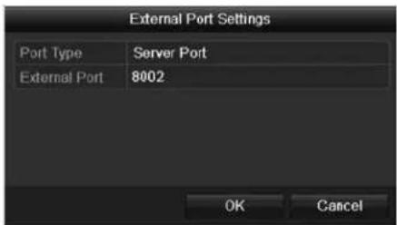
text_image
External Port Settings Port Type Server Port External Port 8002 OK CancelFigure 181, External Port Settings Dialog Box
2) Click √pply to save the settings.
3) Click Refresh to get the latest status of the port mapping.
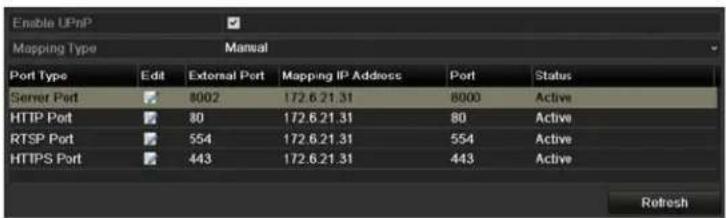
text_image
Enable UPnP Mapping Type Manual Port Type Edit External Port Mapping IP Address Port Status Semer Port 8002 172.6.21.31 8000 Active HTTP Port 80 172.6.21.31 80 Active RTSP Port 554 172.6.21.31 554 Active HTTPS Port 443 172.6.21.31 443 Active RefreshFigure 182, UPnP™ Settings Finished-Manual
11.2.6 Configuring More Settings
-
Enter the ™network Settings interface. Menu > Configuration > Network.
-
™elect the More Settings tab to enter the More Settings interface.
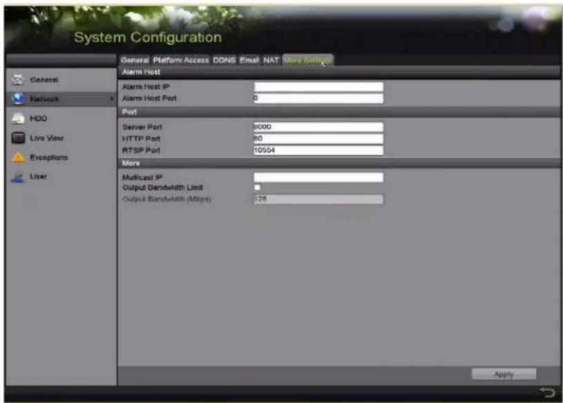
text_image
System Configuration General Platform Access DDNS Email NAT More Settings Alarm Host Alarm Host IP Alarm Host Port 0 Port Server Port 8000 HTTP Port 80 RTSP Port 10554 More Multicast IP Output Bandwidth Limit Output Bandwidth (Mbps) 128 ApplyFigure 183, More ™ettings Interface
- Configure the remote alarm host, server port, HTTP port, multicast, and RT™P port.
- √larm Host IP/Port: With a remote alarm host configured, the device will send the alarm event or exception message to the host when an alarm is triggered. The remote alarm host must have the CM™ (Client Management™ystem) software installed.
The Alarm Host IP refers to the IP address of the remote PC on which the CM™ (Client Management™ystem) software (e.g., iVM™-4200) is installed, and the Alarm Host Port must be the same as the alarm monitoring port configured in the software (default port is 7200).
- Multicast IP: The multicast can be configured to realize live view for more than the maximum number of cameras through network. A multicast address spans the Class-D IP range of 224.0.0.0 to 23".255.255.255. It is recommended to use the IP address ranging from 23".252.0.0 to 23".255.255.255.
When adding a device to the CM ^TM (Client Management ^TM ystem) software, the multicast address must be the same as the device's multicast IP.
- RTSP Port: RT™P (Real Time™streaming Protocol) is a network control protocol designed for use in entertainment and communications systems to control streaming media servers.
Enter the RT ^TM P port in the RT ^TM P Port text field. The default RT ^TM P port is 554, and you can change it according to different requirements.
- Server Port and HTTP Port™ Enter the ™erver Port and HTTP Port in the text fields. The default ™erver Port is 8000 and the HTTP Port is 80, and you can change them according to different requirements.

NOTE
The ™erver Port should be set to the range of 2000 – 65535 and it is used for remote client software access. The HTTP port is used for remote IE access.
- Output Bandwidth Limit: 'heck the checkbox to enable output bandwidth limit.
- Output Bandwidth: After enabling the output bandwidth limit, enter the output bandwidth into the text field.

NOTE
Output bandwidth limit is used for remote live view and playback.
The minimum output bandwidth is 2 Mbps.
- 'lick to save and exit the interface.
11.2.7 Configuring HTTPS Port
HTTP™ authenticates the Web site and associated Web server that one is communicating with, to protect against man-in-the-middle attacks. Perform the following steps to set the https port number.
If you set the port number to 443 and the IP address is 1"2.0.0.64, access the device by entering https"/1"2.0.0.64"443 in the Web browser.

NOTE
The HTTP ^™ port can be configured only through the Web browser.
- Open Web browser, enter the device IP address, and the Web server will select the language automatically according to the system language and maximize the Web browser.
- Enter the correct user name and password.
- 'lick Login to log in to the device.
- Enter the HTTP™ settings interface, 'onfiguration > Remote 'onfiguration > Network ™ettings > HTTP™'.
- 'reate the self-signed certificate or authorized certificate.
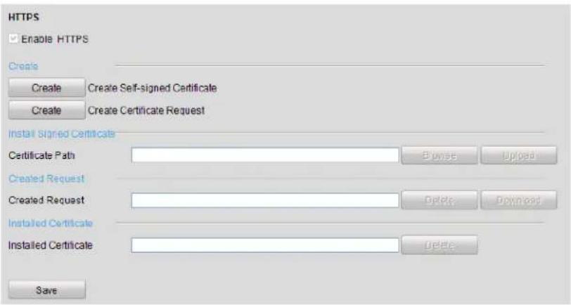
text_image
HTTPS Enable HTTPS Create Create Self-signed Certificate Create Certificate Request Install Signed Certificates Certificate Path Browse Updated Created Request Created Request Delete Download Installed Certificate Installed Certificate Delete SaveFigure 184, HTTP™™ettings
• OPTIO™ 1: Create the Self-Signed Certificate
a) 'lick Create to display the following dialog box"
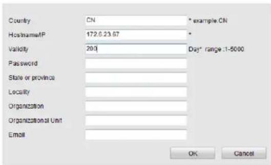
text_image
Country CN * example CN Hostname/P 172.6.23.67 * Validity 200 Day* range:1-5000 Password State or province Locality Organization Organizational Unit Email OK CancelFigure 185, 'reate ™elf-signed 'ertificate
b) Enter the country, host name/IP, validity, and other information.
c) 'lick OK to save the settings.
- OPTIO™ 2: Create the √authorized Certificate
a) 'lick Create to create the certificate request.
b) Download and submit the certificate request to the trusted certificate authority for signature.
c) After receiving the signed valid certificate, import the certificate to the device.
- There will be certificate information after you successfully create and install the certificate.
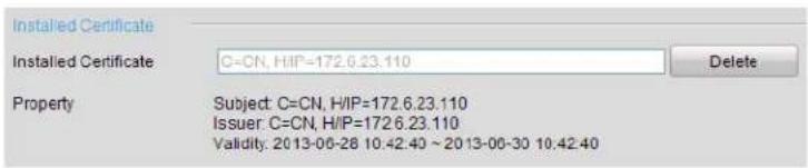
text_image
Installed Certificate Installed Certificate C=CN, HIP=172.6.23.110 Delete Property Subject: C=CN, H/IP=172.6.23.110 Issuer: C=CN, H/IP=172.6.23.110 Validity: 2013-06-28 10:42.40 ~ 2013-06-30 10:42.40Figure 186, Installed 'ertificate Property
- Check the checkbox to enable the HTTP ^TM function.
- Click Save to save the settings.
••.2.8 Configuring E-Mail
The system can be configured to send an e-mail notification to designated users if an event is detected, e.g., an alarm or motion event is detected, etc.
Before configuring the e-mail settings, the DVR must be connected to a local area network (LAN) that maintains an ™MTP mail server. The network must also be connected to either an intranet or the Internet depending on the location of the e-mail accounts to which you want to send notification. Additional, the Preferred DN™ ™Server must be configured.
•.2.8.• Before Starting
Configure the IPv4 Address, IPv4 ^TM ubnet Mask, IPv4 Gateway, and the Preferred DN ^TM ^TM erver in the Network ^TM ettings menu. Refer to Chapter •Configuring General ^TM ettings for detailed information.
•.2.8.2 -rocedure
- Enter the TM network Settings interface, Menu > Configuration > Network.
- ™elect the Email tab to enter the Email Settings interface.
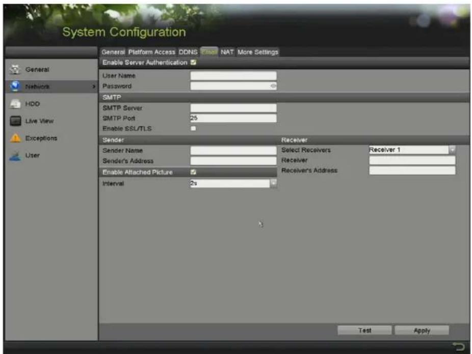
text_image
System Configuration General Platform Access DDNS Email NAT More Settings Enable Server Authentication User Name Password SMTP SMTP Server SMTP Port 25 Enable SSL/TLS Sender Receiver Sender Name Select Receivers Receiver 1 Sender's Address Receiver Enable Attached Picture Receivers Address Interval 2s Test ApplyFigure 187, E-mail ™ettings Interface
3. Configure the following e-mail settings"
- Enable Server √authentication (optional): Check the checkbox to enable the server authentication feature.
- User™ame: The sender's e-mail user account for ™MTP server authentication
- Password: The password of sender's e-mail for ™MTP server authentication
- SMTP Server: The ™MTP ™server IP address or host name (e.g., smtp.263xmail.com)
- SMTP Port: The ™MTP port. The default TCP/IP port used for ™MTP is 25.
- Enable SSL (optional): Click the checkbox to enable ^TM if required by the ^TM MTP server.
- Sender: The name of sender
- Sender's : The e-mail address of sender
- Select Receivers: ^TM elect the receiver. ...p to three receivers can be configured.
• Receiver: The name of the receiver of the e-mail - Receiver's : The e-mail address of the receiver
- Enable √ttached Picture: Check the checkbox if you want to send e-mail with attached alarm images. The interval is the time between two captures of the alarm images.
i NOTE
For IP cameras, the alarm images are directly sent as attached images by e-mail. One image can be sent for one IP camera. Attached images of the linked cameras cannot be sent.
For analog cameras, three attached images can be sent for one analog camera when the alarm is triggered.
• Interval: Refers to the time between sending attached images.
- E-mail Test: ™ends a test message to verify that the ™MTP server can be reached.
4. Click √pply to save the e-mail settings.
5. Click Test to test whether your e-mail settings work. The corresponding Attention message box pops up.
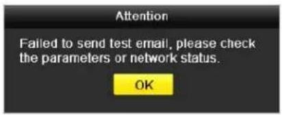
text_image
Attention Failed to send test email, please check the parameters or network status. OK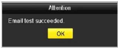
text_image
Attention Email test succeeded. OKFigure 188, Email Testing Attention
••.2.9 Checking ™network Traffic
√ou can check the network traffic to obtain real-time D-R information such as linking status, MT..., sending/receiving rate, etc.
- Enter the TM network Traffic interface, Menu > Maintenance > Net Detect.
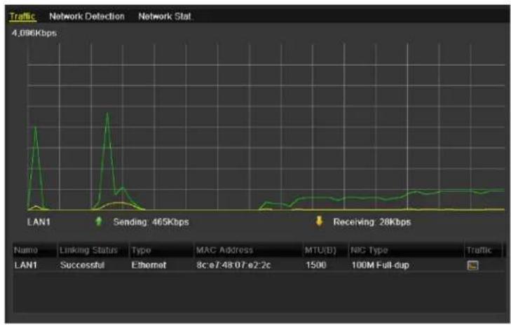
line
| Time | Value | |------|-------| | LAN1 | 465Kbps | | Receiving | 28Kbps |Figure 18", Network Traffic Interface
- √ou can view the sending rate and receiving rate information. The traffic data is refreshed every second.
••.3 Configuring ™Network Detection
√ou can obtain network connecting status of D-R through the network detection function, including network delay, packet loss, etc.
••.3.• Testing ™network Delay and –acket Loss
- Enter the ™network Traffic interface, Menu > Maintenance > Net Detect.
- 'lick the TM network Detection tab to enter the TM network Detection interface.
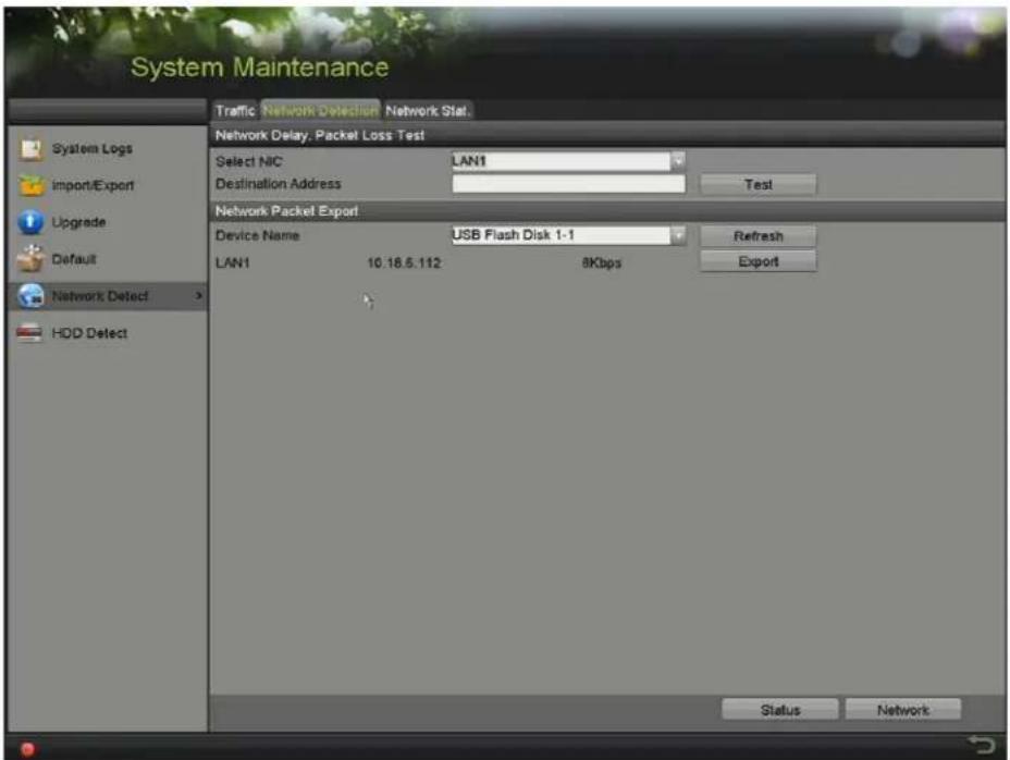
text_image
System Maintenance Traffic Network Detection Network Stat. Network Delay, Packet Loss Test Select NIC LAN1 Destination Address Test Network Packet Export Device Name USB Flash Disk 1-1 Refresh LAN1 10.18.6.112 8Kbps Export Status NetworkFigure 1"0, Network Detection Interface
- ™elect a NI' to test network delay and packet loss.
- Enter the destination address in the text field of Destination √ddress.
- 'lick the Te st button to start testing network delay and packet loss.
•.3.2 Exporting ^TM network –acket
By connecting the D-R to a network, the captured network data packet can be exported to a ...TMB flash disk, or other local backup device.
- Enter the Network Traffic interface, Menu > Maintenance > Net Detect.
- 'lick the TM network Detection tab to enter the TM network Detection interface.
- ™ elect the backup device from the Device ™ame drop-down list.

"lick the "efresh button if the connected local backup device is not displayed. If the system fails to detect the backup device, check whether it is compatible with the D-R. √ou can format the backup device if the format is incorrect.
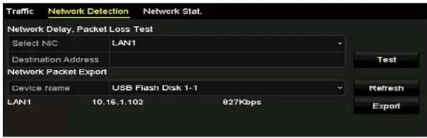
text_image
Traffic Network Detection Network Stat. Network Delay, Packet Loss Test Select NIC LAN1 Destination Address Test Network Packet Export Device Name USB Flash Disk 1-1 LAN1 10.16.1.102 827Kbps Refresh ExportFigure 1"1, Export Network Packet
- 'lick Export to start exporting.
- After exporting is complete, click 'K to finish the packet export.
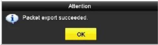
text_image
Attention Packet export succeeded. OKFigure 1"2, Packet Export Attention

...p to 1 MB of data can be exported each time.
••.3.3 Checking ™Network Status
√ou can check the network status and quickly set the network parameters in this interface.
- Enter the Network Traffic interface, Menu > Maintenan ce > Net Detect.
- 'lick the ™etwork Detection tab to enter the ™etwork Detection interface.
- 'lick Status on the bottom right of the interface.
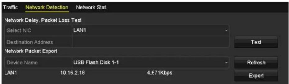
text_image
Traffic Network Detection Network Stat. Network Delay, Packet Loss Test Select NIC LAN1 Destination Address Test Network Packet Export Device Name USB Flash Disk 1-1 LAN1 10.16.2.18 4.671Kbps Refresh ExportFigure 1"3, 'hecking Network™tatus
- If the network is normal the following message box pops out"
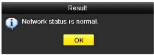
text_image
Result Network status is normal. OKFigure 1"4, Network ™tatus 'hecking Result
- If the message box pops out with information other than this, click the ™network button to show the network parameters quick setting interface.
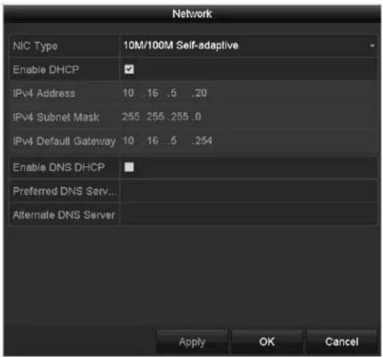
text_image
Network NIC Type 10M/100M Self-adaptive Enable DHCP IPv4 Address 10 .16 .5 .20 IPv4 Subnet Mask 255 255 255 .0 IPv4 Default Gateway 10 .16 .5 .254 Enable DNS DHCP Preferred DNS Serv... Alternate DNS Server Apply OK CancelFigure 1"5, Network Parameters 'onfiguration
••.3.4 Checking ™Network Statistics
'heck the network statistics to obtain the real-time information of the device.
- Enter the TM network Statistics interface, Menu > Maintenance> Net Detect.
- 'lick the ™Network Stat. tab to enter the ™Network Statistics interface.
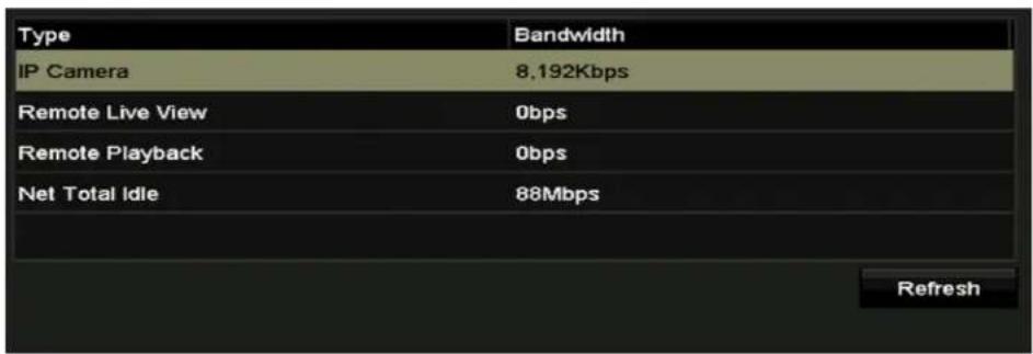
text_image
Type IP Camera 8.192Kbps Remote Live View 0bps Remote Playback 0bps Net Total Idle 88Mbps RefreshFigure 1"6, Network ™tat. Interface
- -iew the Remote •ive -iew bandwidth, Remote Playback bandwidth, and Net Total Idle bandwidth.
- 'lick the "efresh" button to get the latest bandwidth statistics.
Chapter •2 HDD Management
•2. • Initializing HDDs
A newly installed hard disk drive (HDD) must be initialized before it can be used with the D-R.
- Enter the HDD Information interface, Menu >TMystem 'onfiguration >HDD.
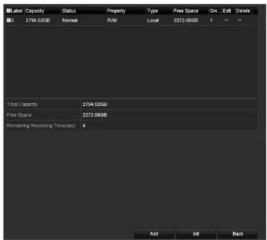
text_image
Label Capacity Status Property Type Free Space Gro...Edit Delete 3 2794.52GB Normal R/W Local 2272.00GB 1 — — Total Capacity 2794.52GB Free Space 2272.00GB Remaining Recording Time(day) 4 Add Init BackFigure 1"7, HDD Information Interface

NOTE
√ou can view the Total 'apacity, Free™pace, and Remaining Recording Time of the HDD. The algorithm of the Remaining Recording Time uses average bit rate for the channel enabling smart encoding to raise accuracy.
- ™elect the HDD to be initialized.
- 'lick Init.
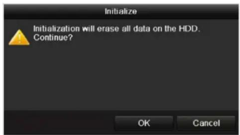
text_image
Initialize Initialization will erase all data on the HDD. Continue? OK CancelFigure 1"8, 'onfirm Initialization
- ™elect 'K to start initialization.

text_image
L... Capacity Status Property Type Free Space Gr... Edit D... 1 931.51GB Formatting 34% R/W Local 0MB 1 -Figure 1 ^™ , TMtart Initialization
- After the HDD has been initialized, the HDD status will change from ...ninitialized to Normal.
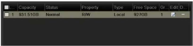
text_image
L... Capacity Status Property Type Free Space Gr... Edit D... 1 931.51GB Normal RW Local 927GB 1 -Figure 200, HDD ^TM tatus Changes to Normal

NOTE
Initializing the HDD will erase all data on it.
HDDs that haven't been accessed for a long period of time can be configured to sleep, thus decreasing the device's power consumption and extending the life of the HDDs.
- Click Menu > HDD > Advanced

text_image
HDD Information Record Information Storage Mode Cloud Storage H.264+/H.265+ for All the Analog ... Enable Enable HDD Sleeping Overwrite ✓ Enable HDD Sie... ✓Figure 201, Enable HDD ™leeping
-
Check the Enable HDD Sleeping checkbox (default), and the HDDs that haven't been accessed for a long period of time will be set to sleep.
-
...ncheck the Enable HDD Sleeping checkbox, and the HDDs will be set to work at all times.
•2.2 Managing ™network HDD
√ou can add an allocated NA ^TM or IP ^TM AN disk to the DVR and use it as a network HDD.
- Enter the HDD Information interface, Menu > HDD > General.

text_image
Property Type Free Space Gr Edit D 1 931.51GB Normal R/W Local 927GB 1Figure 202, HDD Information Interface
- Click to enter the ^TetHDD interface, as shown in 0.
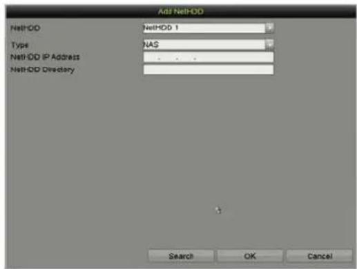
text_image
Add NetHDD NetHDD NetHDD 1 Type NAS NetHDD IP Address NetHDD Directory Search OK CancelFigure 203, NetHDD Information Interface
- Add the allocated NetHDD.
- ™et the type to NA™ or IP ™AN.
- Configure the NA ^TM or IP ^TM AN settings.
- a^TM Disk
a) Enter the NetHDD IP address in the text field.
b) Click Search to search the available NA ^TM disks.
c) ™elect the NA™ disk from the list, or enter the directory in the ™etHDD Directory text field.
d) Click 'K to add the configured NA ^TM disk.

NOTE
...p to eight NA ^TM disks can be added.
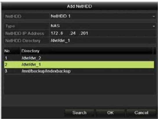
text_image
Add NetHDD NetHDD NetHDD 1 Type NAS NetHDD IP Address 172.6 .24 .201 NetHDD Directory /dvr/dvr_1 No. Directory 1 /dvr/dvr_2 2 /dvr/dvr_1 3 /mnt/backup/indexbackup Search OK CancelFigure 204, Add NA ^TM Disk
- an I-S
a) Enter the NetHDD IP address in the text field.
b) Click Search for the available IP ^TM AN disks.
c) ™elect the IP ™AN disk from the list.
d) 'lick 'K to add the selected IP ^TM AN disk.

NOTE
...p to eight IP ^TM AN disks can be added.
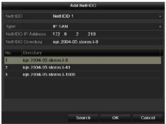
text_image
Add NetHDD NetHDD NetHDD 1 Type IP SAN NetHDD IP Address 172 .9 .2 .210 NetHDD Directory ign.2004-05.storos.l-8 No. Directory 1 ign.2004-05.storos.l-8 2 ign.2004-05.storos.l-41 3 ign.2004-05.storos.l-1000 Search OK CancelFigure 205, Add IP ^TM AN Disk
- After having successfully added the NA ^TM or IP ^TM AN disk, return to the HDD Information menu. The added NetHDD will be displayed in the list.

NOTE
If the added NetHDD is uninitialized, select it and click the Init button for initialization.
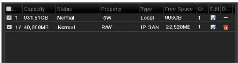
text_image
L... Capacity Status Property Type Free Space Gr... Edit D... ✓ 1 931.51GB Normal RAW Local 906GB 1 ✓ 17 40,000MB Normal RAW IP SAN 22,528MB 1Figure 206, Initialize Added NetHDD
•2.3 Managing HDD Groups
•2.3.• Setting HDD Groups
Multiple HDDs can be managed in groups. –ideo from specified channels can be recorded onto a particular HDD group through HDD settings.
- Enter the ™torage Mode interface, Menu > HDD > Advanced.
- ™et the Mode to Group, as shown in 0.
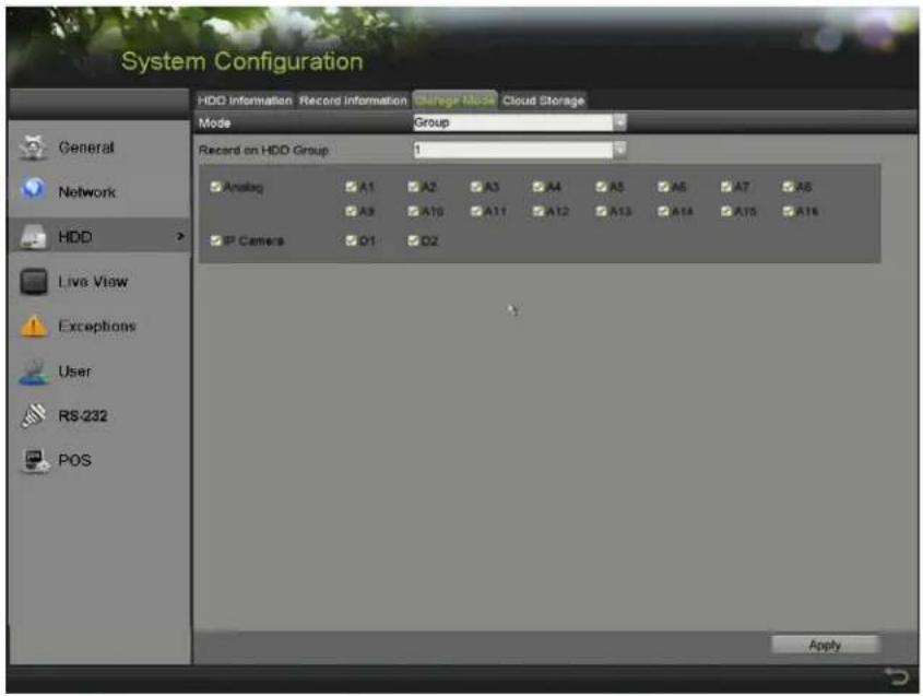
text_image
System Configuration HDD Information Record Information Charge Mode Cloud Storage Mode Group Record on HDD Group 1 Analog A1 A2 A3 A4 A5 A6 A7 A8 A9 A10 A11 A12 A13 A14 A15 A16 IP Camera Q1 D2 Live View Exceptions User RS-232 POS ApplyFigure 207, ^TM storage Mode Interface
- 'lick √pply and the following Attention box will pop up.
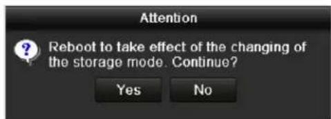
text_image
Attention Reboot to take effect of the changing of the storage mode. Continue? Yes NoFigure 208, Attention for Reboot
- 'lick Yes to reboot the device to activate the changes.
- After device reboot, enter the HDD Information interface, Menu > HDD > General.
- ™elect HDD from the list and click the 📋 icon to enter the Local HDD Settings interface, as shown in 0.
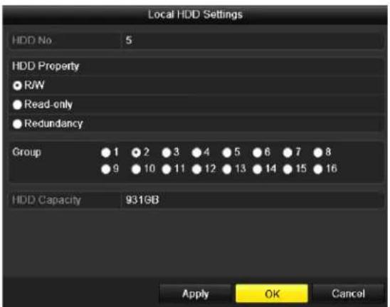
text_image
Local HDD Settings HDD No 5 HDD Property ● R/W ● Read-only ● Redundancy Group 1 2 3 4 5 6 7 8 9 10 11 12 13 14 15 16 HDD Capacity 931GB Apply OK CancelFigure 20", •ocal HDD ™ettings Interface
- ™elect the Group number for the current HDD.

NOTE
The default group no. for each HDD is 1.
- 'lick 'K to confirm the settings.
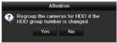
text_image
Attention ? Regroup the cameras for HDD if the HDD group number is changed. Yes NoFigure 210, 'onfirm HDD Group™ettings
“. In the pop-up Attention box, click Yes to finish the settings.
•2.3.2 Setting HDD -property
The HDD can be set to redundancy, read-only, or read/write (R/W). Before setting the HDD property, set the storage mode to Group (see steps 1 – 4 of 'hapter 12.3.1™etting HDD Groups).
A HDD can be set to read-only to prevent important recorded files from being overwritten when the HDD becomes full in overwrite recording mode.
When the HDD property is set to redundancy, the video can be recorded both onto the redundancy HDD and the R/W HDD simultaneously, so as to ensure high security and reliability of video data.
- Enter the HDD Information interface, Menu > HDD > General.
- ™elect HDD from the list and click 📄 to enter the Local HDD Settings interface.
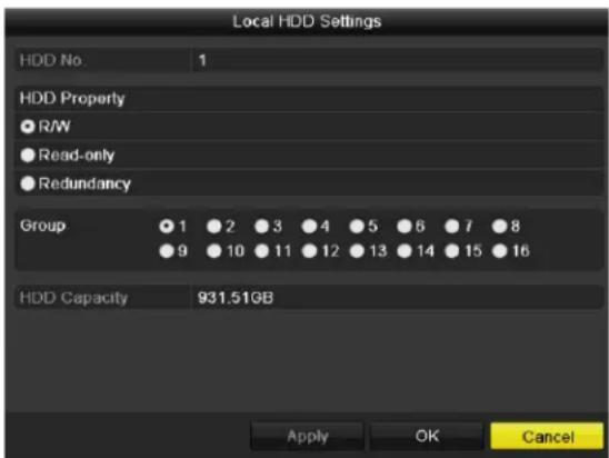
text_image
Local HDD Settings HDD No. 1 HDD Property ● R/W ● Read-only ● Redundancy Group ● 1 ● 2 ● 3 ● 4 ● 5 ● 6 ● 7 ● 8 ● 9 ● 10 ● 11 ● 12 ● 13 ● 14 ● 15 ● 16 HDD Capacity 931.51GB Apply OK CancelFigure 211, ™et HDD Property
- ™et the HDD property to R/W, Read-only, or Redundancy.
- 'lick 'K to save the settings and exit the interface.
- In the HDD Information menu, the HDD property will be displayed in the list.

NOTE
At least two hard disks must be added to the DVR when to set an HDD to Redundancy, with one HDD set to R/W property.
-2.4 Configuring "uota Mode
Each camera can be configured with allocated quota for the storage of recorded files.
- Enter the Storage Mode interface, Menu > HDD > Advanced.
- Click the Storage Mode tab.
- ™et the Mode to ≤uota, as shown in 0.

NOTE
The DVR must be rebooted to enable the changes to take effect.
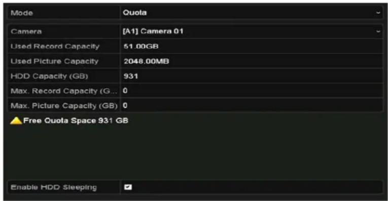
text_image
Mode Quola Camera [A1] Camera 01 Used Record Capacity 51.00GB Used Picture Capacity 2048.00MB HDD Capacity (GB) 931 Max. Record Capacity (G... 0 Max. Picture Capacity (GB) 0 ▲ Free Quola Space 931 GB Enable HDD SleepingFigure 212, ^TM storage Mode ^TM ettings Interface
- ™elect a camera for which you want to configure quota.
- Enter the storage capacity in the Max. "ecord Capacity (GB) text field."
- Copy the current camera's quota settings to other cameras if desired. Click Copy to enter the Copy Camera interface, as shown in 0.
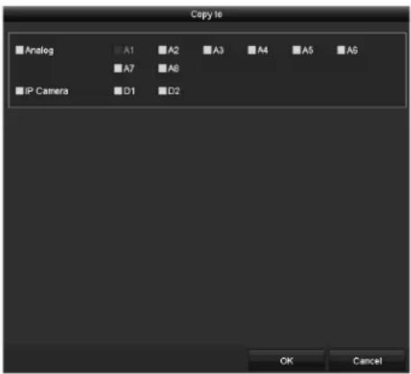
text_image
Copy te Analog A1 A2 A3 A4 A5 A6 A7 A8 IP Camera D1 D2 OK CancelFigure 213, Copy ™ettings to Other Camera(s)
- ™elect the camera(s) to be configured with the same quota settings. √ou can click the Analog checkbox to select all cameras.
- 'lick 'K to finish the 'opy settings and go back to the ™torage Mode interface.
". 'lick √pply to apply the settings.

If the quota capacity is set to Q, then all cameras will use the total HDD capacity for records.
•2.5 Configuring Cloud Storage
'loud storage facilitates you to upload and download recorded files at any time and any place, which can highly enhance efficiency.
- Enter the 'loud™torage interface, Menu > HDD > General > 'loud™torage.
- 'heck the Enable Cloud checkbox to enable the feature.
- ™et the Cloud Type from the drop-down list to One Drive, Google Drive, or Drop Box.
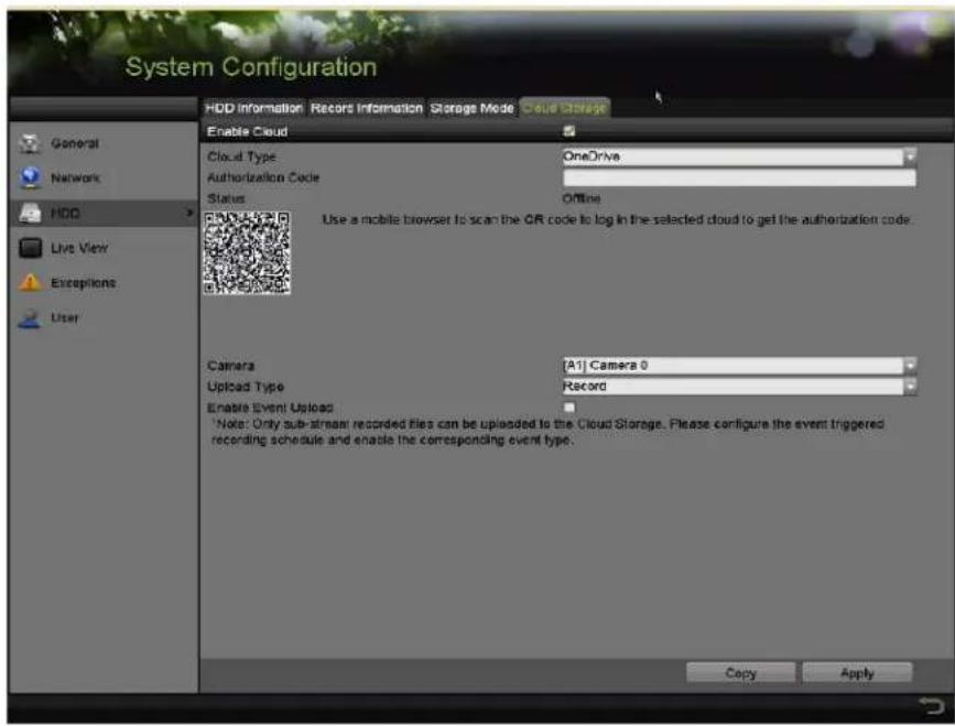
text_image
System Configuration HDD Information Records Information Storage Mode Cloud Storage Enable Cloud Cloud Type OneDrive Authorization Code Status Offline Use a mobile browser to scan the QR code to log in the selected cloud to get the authorization code. Camera [A1] Camera 0 Upload Type Record Enable Event Upload Note: Only sub-stream recorded files can be uploaded to the Cloud Storage. Please configure the event triggered recording schedule and enable the corresponding event type. Copy ApplyFigure 214, 'loud™torage Interface
-
Follow the prompts and use a mobile browser to scan the ≤ R code to log in the selected cloud to get the authentication code. Then copy the authentication code to the Code text field.
-
'lick √pply
-
Go back to the main menu.
-
Enter the cloud storage interface again about 20s later. When the Status shows online, it indicates successful registration.
- 'onfigure the recording schedule.
a) Go back to enter the record interface.
b) 'hoose a camera from the Camera drop-down list.
c) 'heck the Enable Schedule checkbox to enable the schedule recording. For detailed recording schedule information, refer to 5.2 'onfiguring Recording™schedule'.
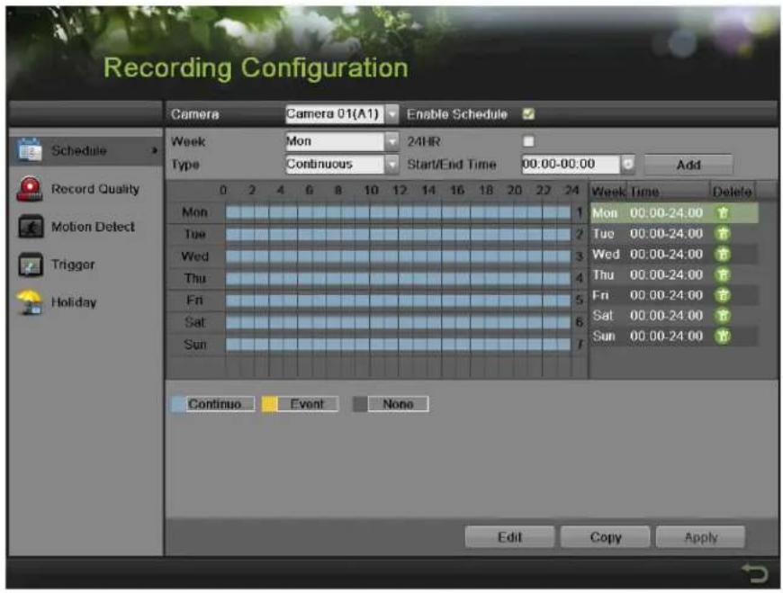
text_image
Recording Configuration Camera Camera 01(A1) Enable Schedule Schedule Record Quality Motion Detect Trigger Holiday Week Mon 24HR Type Continuous Start/End Time 00:00-00:00 Add 0 2 4 6 8 10 12 14 16 18 20 22 24 Mon Tue Wed Thu Fri Sat Sun 1 Mon 00.00-24.00 2 Tue 00.00-24.00 3 Wed 00.00-24.00 4 Thu 00.00-24.00 5 Fri 00.00-24.00 6 Sat 00.00-24.00 7 Sun 00.00-24.00 Continuous Event None Edit Copy ApplyFigure 215, Record ™ schedule
“...pload the event triggered recording files to the cloud storage.
a) Go back to enter the cloud storage interface.
b) ™elect the camera you have set in the recording schedule interface.
c) ™elect the upload type in the Upload Type text filed.
d) 'heck the Enable Event Upload checkbox.
e) 'lick √pply to finish the settings.
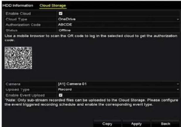
text_image
HDD Information Cloud Storage Enable Cloud ✓ Cloud Type OneDrive Authorization Code ABCDE Status Offline Use a mobile browser to scan the QR code to log in the selected cloud to get the authorization code. Camera [A1] Camera 01 Upload Type Record Enable Event Upload ✓ *Note: Only sub-stream recorded files can be uploaded to the Cloud Storage. Please configure the event triggered recording schedule and enable the corresponding event type. Copy Apply BackFigure 216, ...pload to 'loud™torage Interface

NOTE
Only sub-stream record files can be uploaded to 'loud™torage.
'onfigure the event triggered recording schedule and enable the corresponding event type.
f) (Optional) 'lick Copy to copy the cloud storage settings to other cameras. √ou can also click the Analog/IP 'amera checkbox to select all cameras.
- 'lick OK to go back to the cloud storage interface and click √pply to finish the settings.
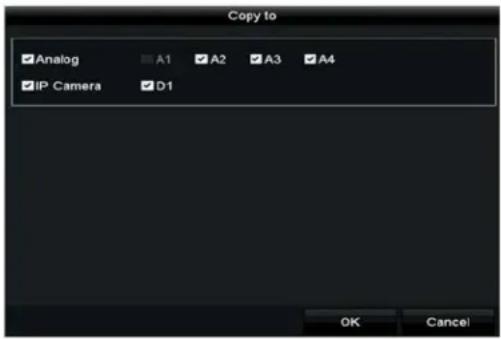
text_image
Copy to Analog A1 A2 A3 A4 IP Camera D1 OK CancelFigure 217, 'opy to Interface
12.6 Checking HDD Status
'heck the status of installed HDDs so as to take immediate maintenance in case of HDD failure.
- Checking HDD Status in HDD Information Interface
- Enter the HDD Information interface, Menu >TMystem 'onfiguration >HDD.
- 'heck the status of each HDD that is displayed on the list, as shown in 0.

text_image
L... Capacity Status Property Type Free Space Gr... Edit D... 1 931.51GB Normal RAW Local 900GB 1 17 199.97GB Normal Redundancy NAS 182GB 1Figure 218, -iew HDD ^TM tatus (1)

NOTE
If the HDD status is Normal or ^TM leeping it works normally. If the status is ...initializedor Abnormal, initialize the HDD before use. If the HDD initialization fails, replace it with a new one.
- Checking HDD Status in System Information Interface
- Enter the System Information interface, Menu > Maintenance > ™ystem Info.
- 'lick the HDD tab to view the status of each HDD displayed on the list, as shown in 0.
| Label | Status | Capacity | Free Space | Property | Type | Group |
| 1 | Normal | 931.51GB | 900GB | R/W | Local | 1 |
| 17 | Normal | 199.97GB | 182GB | Redundancy | NAS | 1 |
Figure 21", View HDD ™tatus (2)
•2.7 Checking S.M.√."T. Information
The ^TM .M.A.R.T.( ^TM elf-Monitoring, Analysis, and Reporting Technology)is an HDD monitoring system to detect and report on various reliability indicators in the hopes of anticipating failures.
- Enter the HDD Detect interface, Menu > Maintenance > HDD Detect.
- Click the S.M. .” .T. Settings tab to enter the interface.
- ™ elect the HDD to analyze.
- Click Test to start analyzing the selected HDD.
- View the HDD's ^TM .M.A.R.T. information list once the analysis is complete.

NOTE
If you want to use the HDD even if the ™.M.A.R.T. checking has failed, check the Continue to use this disk when self-evaluation is failed checkbox.
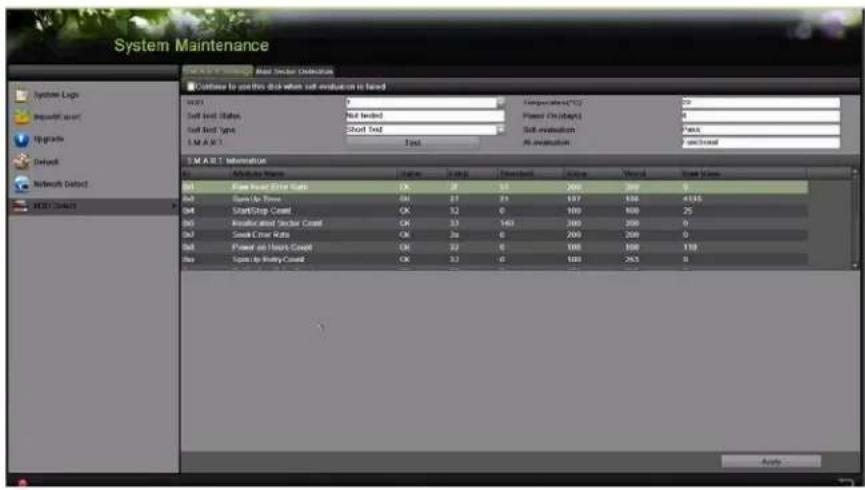
text_image
System Maintenance Continue to use this disk when soft evaluation is based M1:01 Soft Load Status Soft Load Type 1 M A R 1 Short Test Total Continuous(*) Power On (Mpa) Soft evaluation All evaluation Pens S.M.A.R. 1 Information Active Data Status Balance Stacked Threshold Balance Weighted Base Data M1 Save Speed Sheet Rate CK 28 53 200 200 9 M2 Save Up Time OK 27 23 197 186 4135 M3 Start/Stop Count OK 32 0 100 100 25 M4 Reiterated Factor Count OK 33 140 200 200 0 M5 Start/Stop Rate OK 26 0 200 200 0 M6 Power on Head Control OK 33 0 100 100 119 M7 Start/Stop Count OK 33 0 100 263 9Figure 220, ™.M.A.R.T. ™ettings Interface
•2.8 Detecting Bad Sectors
√ou can detect HDD bad sectors.
- Enter the HDD Detect interface, Menu > HDD > HDD Detect.
- Click the Bad Sector Detection tab to enter the interface.
- ™elect an HDD and click Detect to start detecting.
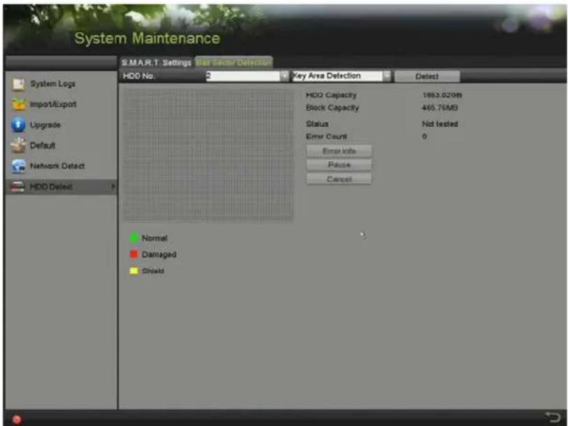
text_image
System Maintenance S.M.A.R.T. Settings Mail Sector Detection HDD No. 2 Key Area Detection Detect System Logs Import/Export Upgrade Default Network Detect HDD Delted ? HDD Capacity 1853.020MB Block Capacity 465.75MB Status Not tested Error Count 0 Error Info Pause Cancel Normal Damaged ShieldFigure 221, Bad ™ector Detecting
-
Click -ause to pause the detection, and click "esume to resume the detection.
-
If the HDD returns error information, click Error Info to view the information.
•2.9 Configuring HDD Error √larms
Configure the HDD error alarms when the HDD status is ...ninitializedor Abnormal.
- Enter the Exception interface, Menu > Configuration > Exceptions.
- ™et the Exception Type to HDD Error from the drop-down list.
-
Check the checkbox(s) below to select the linkage action(s) for HDD error, as shown in Figure 12-26.
-
\Warning\
• ™Motify Surveillance Center - Send E-mail
- Trigger √larm 'utput
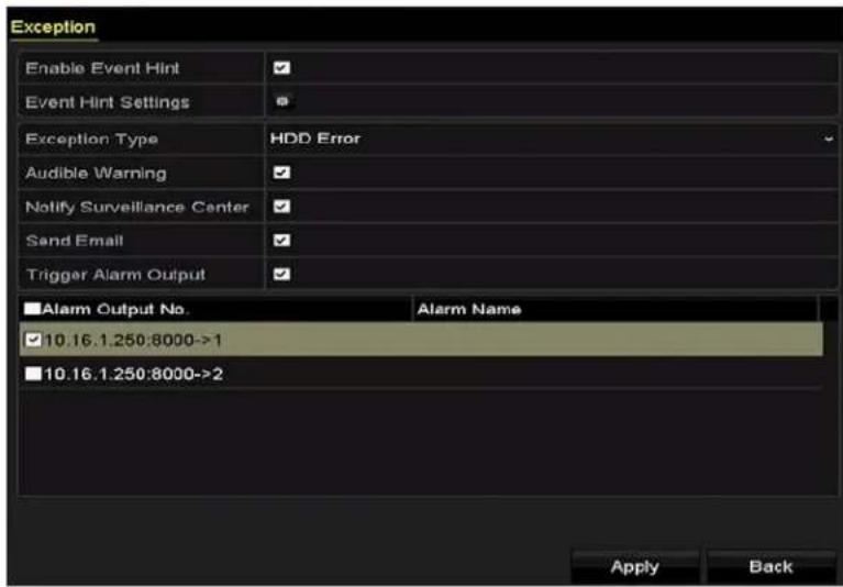
text_image
Exception Enable Event Hint Event Hint Settings Exception Type HDD Error Audible Warning Notify Surveillance Center Sand Email Trigger Alarm Output ■ Alarm Output No. Alarm Name ✓ 10.16.1.250:8000->1 ■ 10.16.1.250:8000->2 Apply BackFigure 222, 'onfigure HDD Error Alarm
- If Trigger √larm 'output is selected, select the alarm output to be triggered from the list below.
- 'lick √pply to save the settings.
Chapter •3 Camera Settings
•3. • √ssigning 5 M- Long Distance Transmission
...se this section to set 5 MP long distance transmission to extend the range of 5 MP cameras.
- Enter the TMignal Input TMtatus interface, Menu > 'ameras TMetup > TMignal Input TMtatus.
- 'heck the 5MP •ong Distance Transmission checkbox to display the analog camera choices window.
- 'heck the analog camera checkboxes that you wish to apply 5 MP •ong Distance Transmission.
- 'lick √pply.
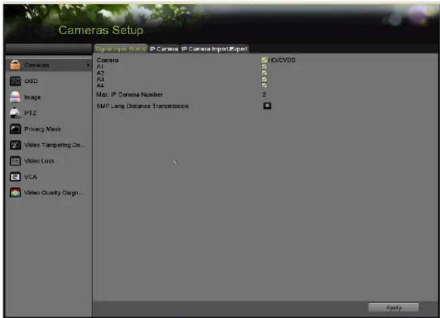
text_image
Cameras Setup Signal Liquid Status IP Camera IP Camera Import/Export Camera A1 A2 A3 A4- Max. IP Camera Number 2 6MP Long Distance Transmission ApplyFigure 223, Menu > 'ameras TMetup > 'ameras > TMignal Input TMtatus

NOTE
5MP •ong Distance Transmission is the only setting functional on this page for this D-R series.
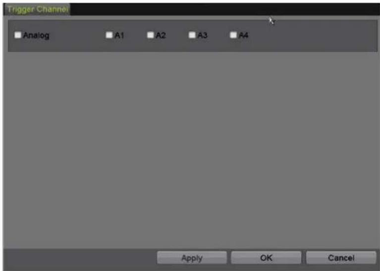
text_image
Trigger Channel Analog A1 A2 A3 A4 Apply OK CancelFigure 224, 5 MP •ong Distance Transmission Analog 'amera 'hoices
•3.2 Configuring 'SD Settings
'onfigure the O™D (On-™creen Display) settings for the camera, including date/time, camera name, etc.
- Enter the O ^TM D 'onfiguration interface, Menu > 'ameras ^TM etup > O ^TM D.
- ™elect the camera to configure O™D settings.
- Edit the Camera ™ame in the text field.
- 'onfigure the Display™ame, Display Date, and Display Week by checking the checkbox.
- ™elect the Date Format, Time Format, Display Mode, and the 'SD Font (this setting is available in the Web interface only).
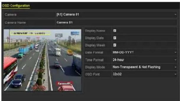
text_image
OSD Configuration Camera [A1] Camera 01 Camera Name Camera 01 Display Name Display Date Display Week Date Format MM-OD-YYYY Time Format 24-hour Display Mode Non-Transparent & Not Flashing OSD Font 32x32Figure 225, O™D 'onfiguration Interface
- ...se the mouse to drag the text frame on the preview window to adjust the O ^TM D position.
- 'opy 'amera™ettings
a) To copy the O™D settings of the current camera to other cameras, click Copy to enter the Copy Camera interface, as shown in 0.
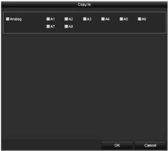
text_image
Copy to Analog A1 A2 A3 A4 A5 A6 A7 A8 OK CancelFigure 226, 'opy™ettings to Other 'ameras
b) ™elect the camera(s) to be configured with the same O™D settings. √ou can also check the √nalog checkbox to select all cameras.
c) 'lick 'K to finish the Copy settings and go back to the 'SD Configuration interface.
- 'lick √pply to apply the settings.
•3.3 Configuring –rivacy Mask
'onfigure the four-sided privacy mask zones that cannot be viewed or recorded by the operator.
- Enter the -rivacy Mask Settings interface, Menu > 'ameras™etup > Privacy Mask.
- ™elect the camera to set privacy mask.
- 'heck the Enable -rivacy Mask checkbox to enable this feature.
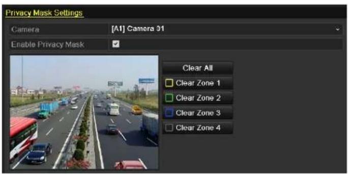
text_image
Privacy Mask Settings Camera [A1] Camera 01 Enable Privacy Mask Clear All Clear Zone 1 Clear Zone 2 Clear Zone 3 Clear Zone 4Figure 227, Privacy Mask™ettings Interface
- ...se the mouse to draw a zone on the window. The zones will be marked with different frame colors.

NOTE
...p to four privacy mask zones can be configured, and the size of each area can be adjusted.
- The configured privacy mask zones on the window can be cleared by clicking the corresponding Clear Zone• - 4 icons on the right side of the window, or click Clear √II to clear all zones.

text_image
Privacy Mask Settings Camera [A1] Camera 01 Enable Privacy Mask Clear All Clear Zone 1 Clear Zone 2 Clear Zone 3 Clear Zone 4Figure 228, ™et Privacy Mask Area
-
Click Copy to copy the privacy mask settings of the current camera to other cameras. Refer to step 7 of Chapter •Configuring O™D™ettings
-
Click √pply to save the settings.
•3.4 Configuring Video Parameters
•3.4.• Configuring Image Settings
- Enter the Image ™ettings interface, Menu > Cameras ™etup > Image > Image ™ettings.
- ™elect the Image Settings tab.
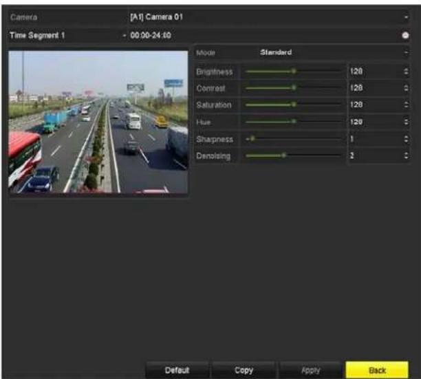
text_image
Camera [A1] Camera 01 Time Segment 1 - 00:00-24:00 Mode Standard Brightness 128 Contrast 128 Saturation 128 Hue 129 Sharpness 1 Denolating 2 Default Copy Apply BackFigure 229, Image™ettings Interface (Analog Camera)
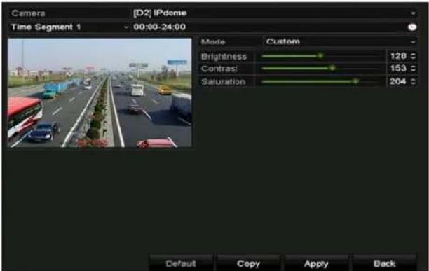
text_image
Camera [D2] IPdome Time Segment 1 - 00:00-24:00 Mode Custom Brightness 128 Contrast 153 Saturation 204 Default Copy Apply BackFigure 230, Image ™ettings Interface (IP 'amera)
- ™ elect the camera to set image parameters.
- ™elect the period name in the drop-down list (two periods are provided).

NOTE
Time periods cannot overlap.
-
™elect the for analog camera mode from the Mode drop-down list.
-
Standard
- Indoor
- Dim Light
-
Outdoor
-
Adjust the image parameters according to actual needs.
- Cameras
a) Brightness
b) 'ontrast
c) ™aturation
d) Hue
e) ™harpness
f) De-noising
- IP Cameras
a) Brightness
b) 'ontrast
c) ™aturation

NOTE
'lick "estore to reset the parameters to the default settings.
- 'lick Copy to copy the image settings of the current camera to other cameras.
- 'lick √pply to save the settings.
•3.4.2 Configuring Camera -parameters Settings
- Enter the Image ™ettings interface, Menu > 'ameras ™etup > Image > 'amera Parameters ™ettings.
- ™elect the 'amera Parameters ™ettings tab.
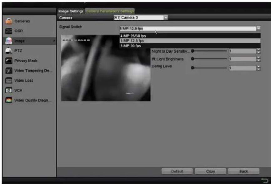
text_image
Image Settings Camera Parameters Settings Camera [A1] Camera 0 Signal Switch: 8 MP 12.5 fps 4 MP 25/30 fps 5 MP 12.5 fps 5 MP 20 fps Night to Day Sensitivity... 1 IR Light Brightness 1 Detog Level 1 PTZ Privacy Mask Video Tampering De... Video Lost VCA Video Quality Diagn... Default Copy BackFigure 231, 'amera Parameters™ettings
- ™elect the Camera from the drop-down list.
- (Optional) ^TM witch the 4 MP or 5 MP signal from the Signal Switch drop-down list. 4 MP 25/30 fps, 5 MP 12.5 fps, and 5 MP 20 fps are selectable. The 4 MP 25 fps and 4 MP 30 fps signals are self-adaptive for the camera.
- (Optional) 'heck the Enable Defog checkbox to enable the defog function of the selected camera, and set the Defog Level from 1 to 4.
- (Optional) Adjust the other camera parameters including Day to TMight Sensitivity, TMight to Day Sensitivity, and I" Light Brightness for the analog cameras. √ou can also click Default to set the parameters to the default settings.
- (Optional) 'lick Copy to copy the parameters of the current camera to other analog cameras.
- 'lick √pply to save the settings.

NOTE
The camera parameters settings are applicable only to analog cameras.
The 4 MP/5 MP ^TM signal ^TM witch, Defog, Day to Night ^TM sensitivity, Night to Day ^TM sensitivity, and IR •ight Brightness functions must be supported by the connected analog camera. √ou cannot set the parameters if the connected analog camera does not support them or there is no video signal.
The parameters are saved to the connected analog camera and are not saved to the D-R.
The default value of Day to Night ^TM ensitivity, Night to Day ^TM ensitivity, and IR •ight Brightness is 5. The effective value ranges from 1 to “.
If you exit from the interface and enter it again, the parameters displayed are those you last set.
The D–R connects to analog cameras via Hikvision- ^4 protocol and there is no response mechanism; even if the Hikvision- ^4 is abnormal, the parameters are still displayed as having been successfully set.
Chapter •4 DV" Management and Maintenance
•4.• Viewing System Information
- Enter the System Information interface, Menu >TMystem Information.
- "lick the Device Info, Camera,"ecord, √larm, ™network and HDD tabs to view the system information of the device.
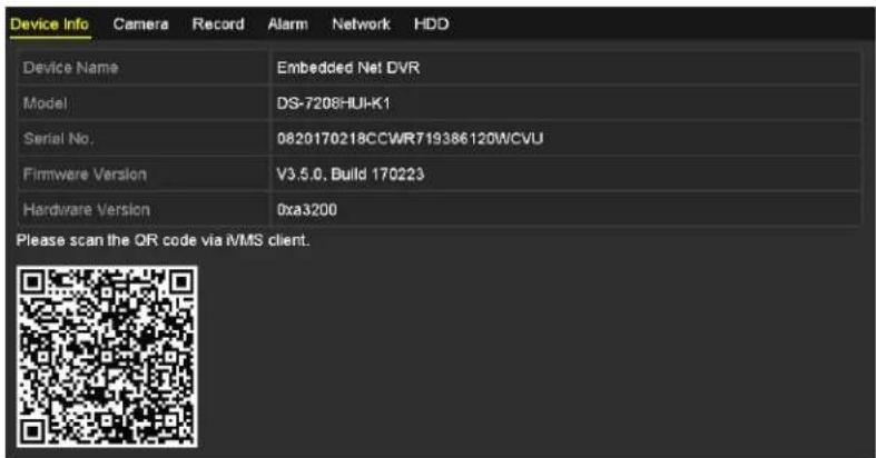
text_image
Device Info Camera Record Alarm Network HDD Device Name Embedded Net DVR Model DS-7208HUI-K1 Serial No. 0820170218CCWR719386120WCVU Firmware Version V3.5.0, Build 170223 Hardware Version 0xa3200 Please scan the QR code via iVMS client.Figure 232, ™ystem Information Interface
•4.2 Searching Log Files
The operation, alarm, exception, and D-R information can be stored in log files, which can be viewed and exported at any time.
- Enter the Log Search interface, Menu > Maintenance > •og Information.
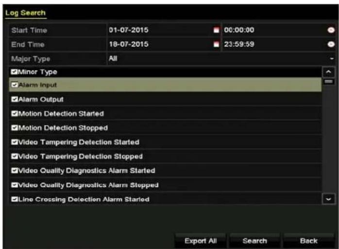
text_image
Log Search Start Time 01-07-2015 00:00:00 End Time 18-07-2015 23:59:59 Major Type All Minor Type Alarm Input Alarm Output Motion Detection Started Motion Detection Stopped Video Tampering Detection Started Video Tampering Detection Stopped Video Quality Diagnostics Alarm Started Video Quality Diagnostics Alarm Stopped Line Crossing Detection Alarm Started Export All Search BackFigure 233, •og ™earch Interface
- ™et the log search conditions to refine your search, including ™tart Time, End Time, Major Type, and Minor Type.
- 'lick Search to start searching log files.
- The matched log files will be displayed on the list shown below.

NOTE
...p to 2,000 log files can be displayed each time.
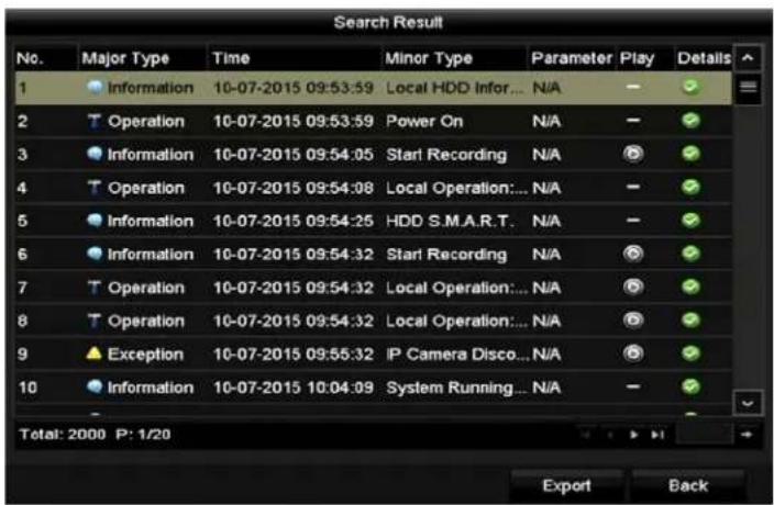
text_image
Search Result No. Major Type Time Minor Type Parameter Play Details 1 Information 10-07-2015 09:53:59 Local HDD Infor... N/A 2 Operation 10-07-2015 09:53:59 Power On N/A 3 Information 10-07-2015 09:54:05 Start Recording N/A 4 Operation 10-07-2015 09:54:08 Local Operation:... N/A 5 Information 10-07-2015 09:54:25 HDD S.M.A.R.T. N/A 6 Information 10-07-2015 09:54:32 Start Recording N/A 7 Operation 10-07-2015 09:54:32 Local Operation:... N/A 8 Operation 10-07-2015 09:54:32 Local Operation:... N/A 9 Exception 10-07-2015 09:55:32 IP Camera Disco...N/A 10 Information 10-07-2015 10:04:09 System Running... N/A Total: 2000 P: 1/20 Export BackFigure 234, •og ™earch Results
- 'click √ of each log or double-click it to view its detailed information. √ou can also click 🔒 to view the related video files if available.
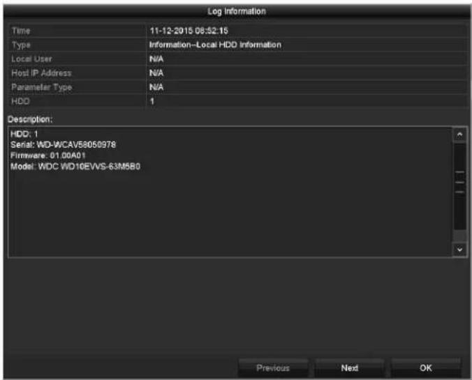
text_image
Log Information Time 11-12-2015 06:52:15 Type Information--Local HDD Information Local User N/A Host IP Address N/A Parameter Type N/A HDD 1 Description: HDD: 1 Serial: WD-WCAV88050978 Firmware: 01.00A01 Model: WDC WD10EVVS-63M5B0 Previous Ned OKFigure 235, •og Information Interface
- To export the log files, click Export to enter the Export menu, as shown in Figure 14-5.
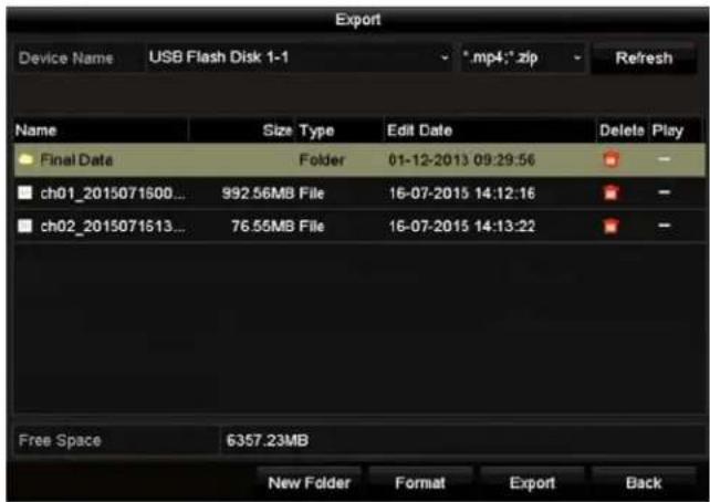
text_image
Export Device Name USB Flash Disk 1-1 *mp4*.zip Refresh Name Size Type Edit Date Delete Play Final Data Folder 01-12-2013 09:29:56 ch01_2015071600... 992.56MB File 16-07-2015 14:12:16 ch02_2015071513... 76.55MB File 16-07-2015 14:13:22 Free Space 6357.23MB New Folder Format Export BackFigure 236, Export •og Files
- ™elect the backup device from the Device ™ame drop-down list.
- 'lick Export to export the log files to the selected backup device.

NOTE
'lick ™ew Folder to create a new folder in the backup device, or click Format to format the backup device before log export.
'onnect the backup device to the D-R before operating log export.
The log files exported to the backup device are named by export time, e.g., 20110514124841logBack.txt.
•4.3 Importing/Exporting I– Camera Info
The added IP camera information can be generated into a Microsoft Excel file and exported to the local device for backup, including the IP address, manage port, admin password, etc. The exported file can be edited on your P' to add or delete content, and the settings can be copied to other devices by importing the Excel file.
- Enter the camera management interface, Menu > 'amera > 'amera.
- 'lick the I- Camera Import/Export tab, and detected plugged external devices appears.
- 'lick Export to export configuration files to the selected local backup device.
- To import a configuration file, select the file from the selected backup device and click Import. After the importing process is completed, you must reboot the D-R.
•4.4 Importing/Exporting Configuration Files
The D-R configuration files can be exported to a local device for backup; and the configuration files of one D-R can be imported to multiple D-R devices if they are to be configured with the same parameters.
- Enter the Import/Export 'onfiguration File interface, Menu > Maintenance > Import/Export.
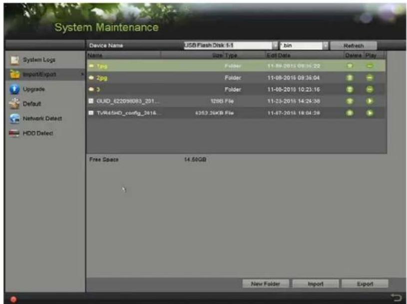
text_image
System Maintenance Device Name USB Flash Disk 1-1 7.bin Refresh Name Size Type Edit Data Delete Play 1.jpg Folder 11-08-2018 09:35:22 2.jpg Folder 11-08-2018 09:35:04 3 Folder 11-08-2018 10:23:16 GUID_622098083_201... 1288 File 11-23-2018 14:24:38 TVR45HD_config_2018... 4352.3KB File 11-07-2018 18:04:58 Free Space 14.50GB New Folder Import ExportFigure 237, Import/Export 'onfiguration File
- 'lick Export to export the configuration files to the selected local backup device.
- To import a configuration file, select the file from the chosen backup device and click Import. After the import process has completed, you must reboot the D-R.

NOTE
After finishing importing the configuration files, the device will reboot automatically.
•4.5 U pgrading System
The firmware on your D-R can be upgraded by local backup device or remote FTP server.
•4.5.• Upgrading by Local Backup Device
- 'onnect your D-R with a local backup device where the update firmware file is located.
- Enter the Upgrade interface, Menu > Maintenance > ...pgrade.
- 'lick the Local Upgrade tab to enter the Local Upgrade interface, as shown in Figure 14-7.
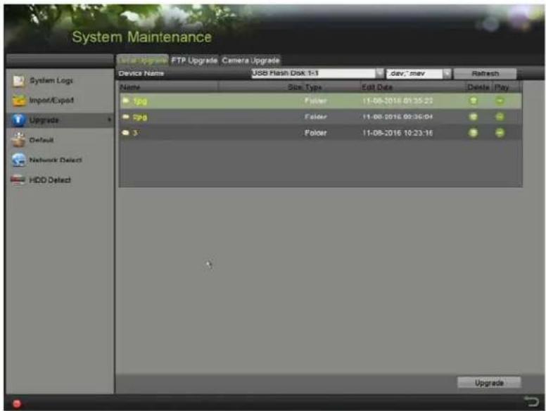
text_image
System Maintenance Local Upgrade FTP Upgrade Camera Upgrade Device Name USB Flash Disk 1-1 dev:*.mov Retash Name Size Type Edit Date Delete Play 1.jpg Folder 11-08-2016 01:35:22 Spyg Folder 11-08-2016 09:36:04 3 Folder 11-08-2016 10:23:16 Upgrade Import/Export Upgrades Default Network Defect HDD Defect UpgradeFigure 238, •ocal ...pgrade Interface
- ™elect the update file from the backup device.
- 'lick Upgrade to start upgrading.
- After upgrading is complete, reboot the D-R to activate the new firmware.
•4.5.2 Upgrading by FT-
'onfigure P' (running FTP server) and D-R to the same •ocal Area Network. Run the third-party TFTP software on the P' and copy the firmware into the root directory of TFTP.
- Enter the Upgrade interface, Menu > Maintenance > ...pgrade.
- 'lick the FT-tab to enter the Local Upgrade interface, as shown in Figure 16-8.
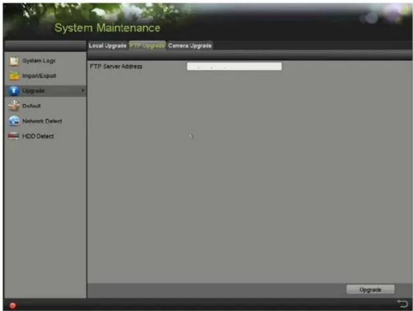
text_image
System Maintenance Local Upgrade FTP Upgrade Camera Upgrade System Logs Import/Export Upgrade Default Network Detect HDD Detect FTP Server Address UpgradesFigure 23", FTP ...pgrade Interface
- Enter the FTP ™erver address in the text field.
- 'lick Upgrade to start upgrading.
- After upgrading is complete, reboot the D-R to activate the new firmware.
•4.6 U pgrading Camera
- √ou can upgrade multiple connected analog cameras supporting TurboHD signal simultaneously with the D-B
- Enter the Camera Upgrade interface, Menu > Maintenance > ...pgrade > 'amera ...pgrade
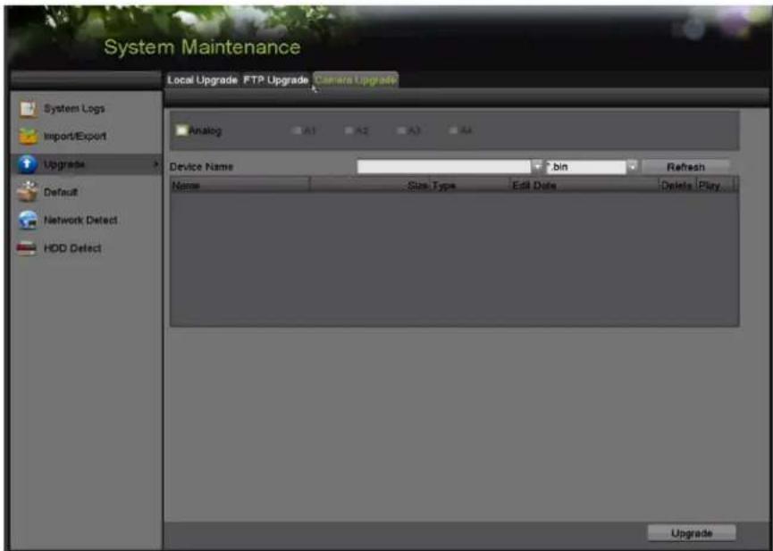
text_image
System Maintenance Local Upgrade FTP Upgrade Camera Upgrade Analog A1 A2 A3 A4 Device Name bin Refresh Name Size Type Edit Date Delete Play Upgrade System Logs Import/Export Upgrade Default Network Detect HDD Defect UpgradeFigure 240, Camera ...pgrade
- Check the analog checkbox.
- Check the camera checkbox(es) to select cameras to upgrade.

NOTE
The analog camera must support TurboHD signal.
- ™ elect the update file from the backup device.
- Click Upgrade to start upgrading.
- 4.7 " estoring Default Settings
- Enter the Default interface, Menu > Maintenance > Default.
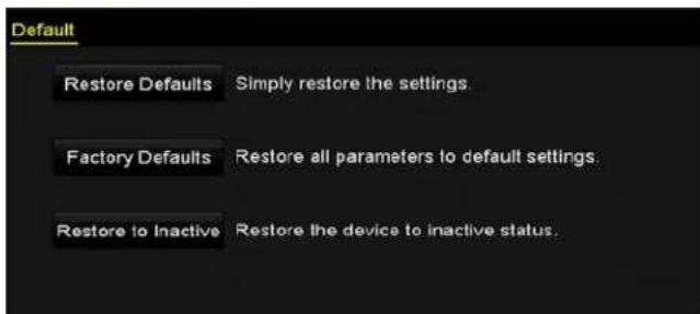
text_image
Default Restore Defaults Simply restore the settings. Factory Defaults Restore all parameters to default settings Restore to Inactive Restore the device to inactive status.Figure 241, Restore Defaults
- ™ elect the restoring type from the following three options:
- "estore Defaults: Restore all parameters, except the network (including IP address, subnet mask, gateway, MT..., NIC working mode, default route, server port, etc.) and user account parameters, to the factory default settings.
• Factory Defaults: Restore all parameters to the factory default settings.
- "estore to Inactive: Restore the device to inactive status."
- Click 'K to restore the default settings.

NOTE
The device will reboot automatically after restoring the default settings.
Chapter •5 'thers
•5.• Configuring General Settings
This section explains how to configure output resolution, system time, mouse pointer speed, etc.
- Enter the General Settings interface, Menu >TMystem Configuration >General.
- ™elect the General tab.

text_image
System Configuration Time/Date Display More Settings Language English Output Standard NTSC VGA/HDMI Resolution 1280*1024/60HZ Mouse Pointer Speed Double Click Speed Enable Password 'Double-click on a blank area to test click speed.Figure 242, General™ettings Interface
- Configure the following settings:
• Language: The default language used is English.
- 'utput Standard: ^TM elect the output standard to be PAL or NT ^TM C.
- VG√/HDMI "resolution: ™elect the output resolution, which must be the same with the resolution of the VGA/HDMI display.
- Mouse -ointer Speed: ^TM et the speed of mouse pointer; four levels are configurable.
- Double Click Speed: ^TM et the speed of mouse double-click; three levels are configurable.
- Enable –assword: Enable/disable the use of the login password.

NOTE
If you check the Enable -assword checkbox, every time you log in to the DVR, the ...nlock Pattern interface will pop up. If you uncheck the Enable -assword checkbox, when you log in to the DVR, the ...nlock Pattern interface will not pop up.
- Click √pply to save the settings.
•5.2 C onfiguring DST Settings
- Enter the General Settings interface, Menu >TMystem Configuration >General >Time/Date.
2. 'hoose the DST Settings tab.
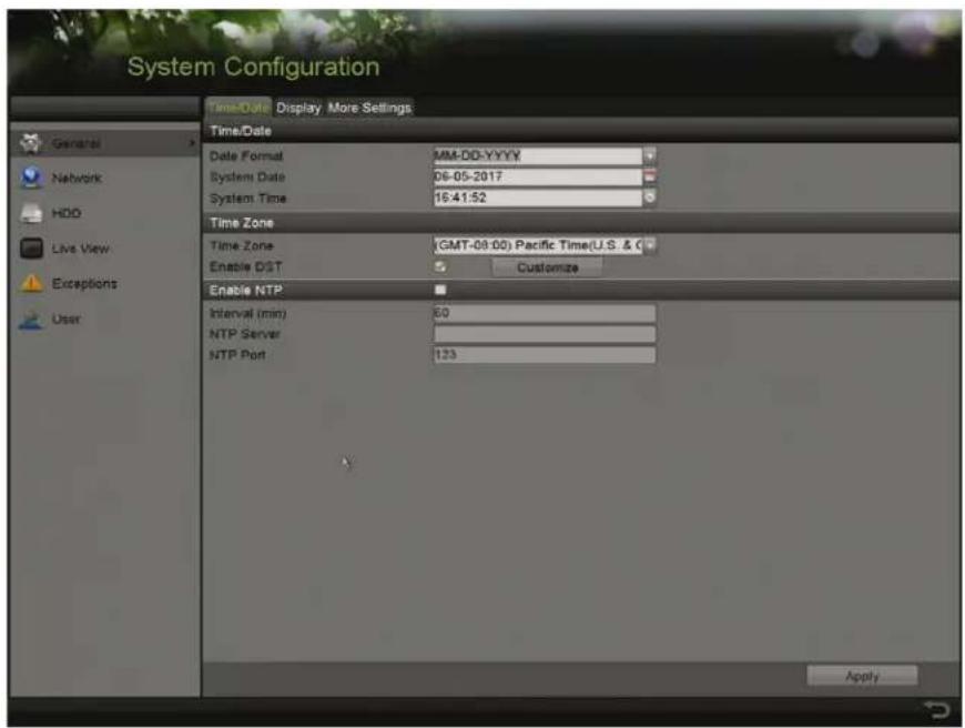
text_image
System Configuration Time/Date Display More Settings Time/Date Date Format MM-DD-YYYY System Date 06-05-2017 System Time 16:41:52 Time Zone Time Zone GMT-09:00) Pacific Time(U.S. & C Enable DST 5 Customize Enable NTP Interval (min) 60 NTP Server NTP Port 123 ApplyFigure 243, Time/Date ™etting
- 'heck the Enable D™T checkbox.
- 'lick CUST'MIZE.
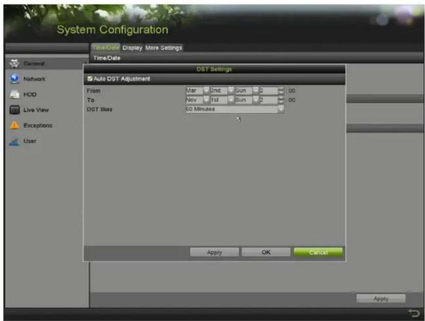
text_image
System Configuration Time/Date Display More Settings Time/Date General Network HDD Live View Exceptions User DST Settings Auto DST Adjustment From Mar 2nd Sun 2 00 To Nov 1st Sun 2 00 DST Bias 60 Minutes Apply OK Cancel ApplyFigure 244, D™T™ettings Interface
√ou can check the checkbox before the √uto DST √djustment item, or you can manually check the Enable DST checkbox and then choose the date of the D™T period.
•5.3 Configuring More Settings
- Enter the General TMettings interface, Menu >TMystem 'onfiguration >General.
- 'lick the More Settings tab to enter the More Settings interface, as shown in the following figures.
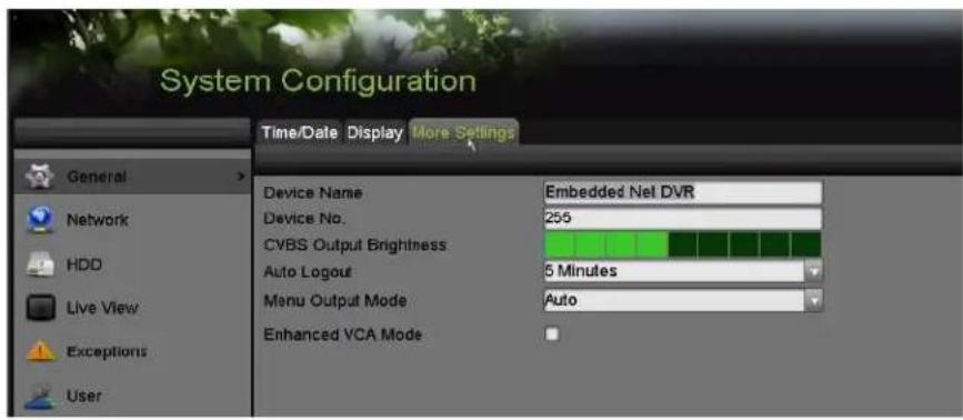
text_image
System Configuration Time/Date Display More Settings General Network HDD Live View Exceptions User Device Name Embedded Net DVR Device No: 255 CVBS Output Brightness Auto Logout 5 Minutes Menu Output Mode Auto Enhanced VCA ModeFigure 245, More™ettings Interface
- Configure the following settings:
• Device ™ame: Edit the DVR name.
- Device™o.: Edit the DVR serial number. The Device No. can be set in the range of 1 to 255 (default No. is 255).
- √uto Logout: ™et timeout time for menu inactivity. E.g., when the timeout time is set to 5 Minutes, the system will exit from the current operation menu to the live view screen after 5 minutes of menu inactivity.
• CVBS 'utput Brightness: Adjust the video output brightness via the CVB™ interface.
- Menu 'utput Mode: √ou can choose the menu display on different video output.
- √uto and HDMI/VG√ are selectable.
- Enhanced VC√Mode: D™-72xxH...I-Kx™eries DVRs support Enhanced VCA Mode, which allows line crossing detection and intrusion detection on all channels. Enhanced VCA Mode conflicts with 2K/4K output and 4 MP/5 MP signal input. Enable or disable VCA mode as needed.

NOTE
D^TM-72xxH ≤ I-Kx^TM eries DVRs don't support Enhanced VCR Mode.
The pop-up will only show mode(2),
- Enable Enhanced VC√ Mode
1) Check the checkbox to enable enhanced VCA mode.
2) Click √pply and the attention box pops up as below.
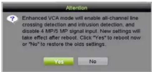
text_image
Attention Enhanced VCA mode will enable all-channel line crossing detection and intrusion detection, and disable 4 MP/5 MP signal input. New settings will take effect after reboot. Click "Yes" to reboot now or "No" to restore the olds settings. Yes NoFigure 246, Enable Enhanced VCA Mode (1)
3) Click Yes to apply the function and reboot the device.

NOTE
Line crossing detection and intrusion detection will function on all channels.
If you have configured 2K/4K output, or connected 4 MP/5 MP signal input, when you enable Enhanced VCA Mode and the device reboots, the output resolution will decrease to 1080p and the 4 MP/5 MP signal input will display no video.
- Disable Enhanced VC√ Mode (Default)
1) ...ncheck the checkbox to disable enhanced –'A mode.
2) 'lick √pply and the attention box pops up as below.
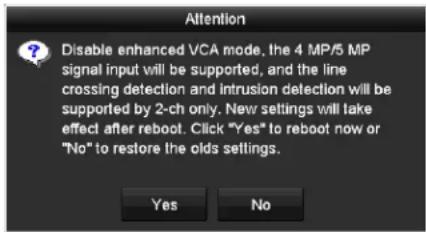
text_image
Attention Disable enhanced VCA mode, the 4 MP/5 MP signal input will be supported, and the line crossing detection and intrusion detection will be supported by 2-ch only. New settings will take effect after reboot. Click "Yes" to reboot now or "No" to restore the olds settings. Yes NoFigure 247, Disable Enhanced -'A Mode (2)
3) 'lick Yes to apply the function and reboot the device.
4) 'lick √pply to save the settings.

NOTE
- line crossing detection and intrusion detection will be supported only on two channels. 2K/4K output and 4 MP/5 MP input signals will be supported.
•5.4 Managing User √ccounts
There is a default account in the D-R" Administrator. The Administrator user name is admin and the password is set when you start the device for the first time. The Administrator has the permission to add and delete users and configure user parameters.
•5.4.• √dding a User
- Enter the User Management interface, Menu >TMystem 'onfiguration >...ser.
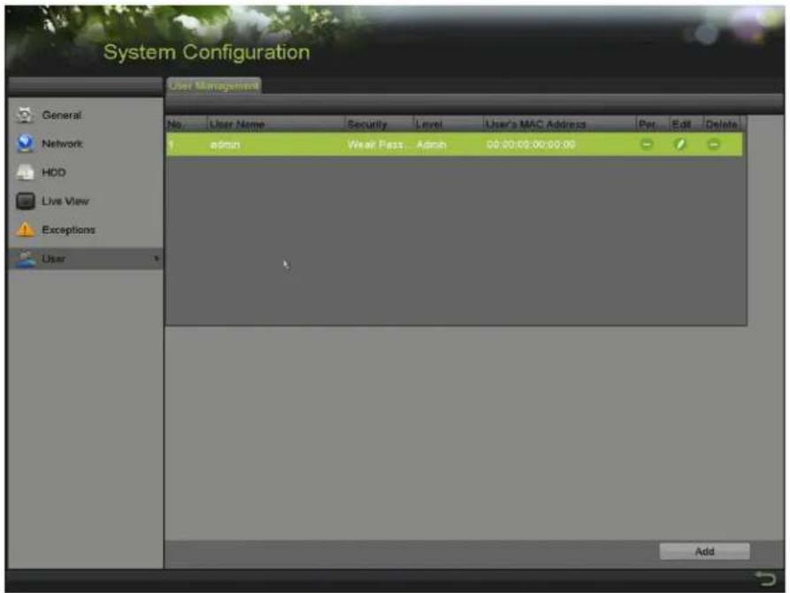
text_image
System Configuration User Management No User Name Security Level User's MAC Address Per Edit Delete admin Wear Pass Admin 00:00:00:00:00:00 AddFigure 248, ...ser Management Interface
- 'lick to enter the User interface.
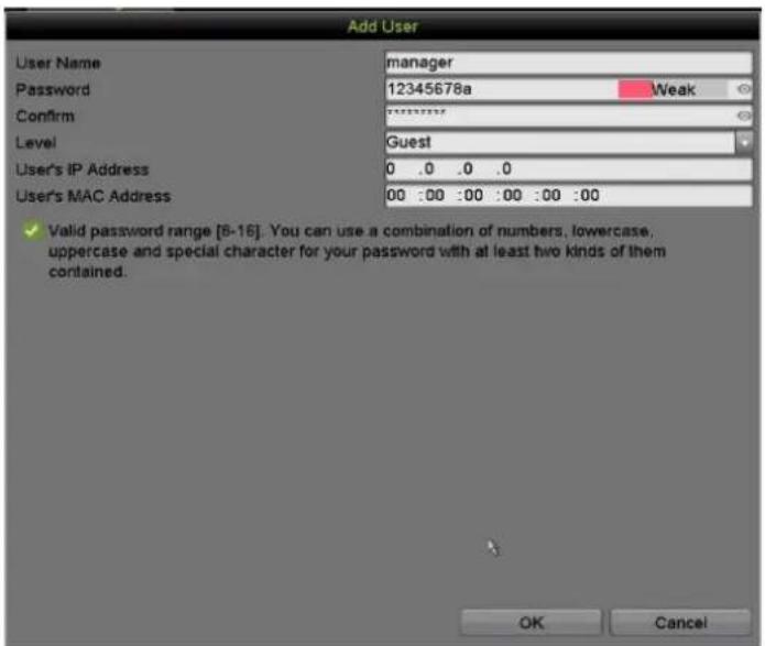
text_image
Add User User Name manager Password 12345678a Weak Confirm { Level Guest User's IP Address 0 .0 .0 .0 User's MAC Address 00 :00 :00 :00 :00 :00 :00 ✓ Valid password range [8-16]. You can use a combination of numbers, lowercase, uppercase and special character for your password with at least two kinds of them contained. OK CancelFigure 24", Add ...ser Menu
- Enter information for the new user"
- Password: ™et the password for the user account.

WARNING
STRO™G P√SSWORD RECOMME™DED – We highly recommend you create a strong password of your own choosing (using a minimum of eight characters, including at least three of the following categories" upper case letters, lower case letters, numbers, and special characters.) in order to increase the security of your product. We also recommend you reset your password regularly. Resetting the password monthly or weekly can better protect your product.
- Level: ^TM et the user level to Operator or Guest. Different user levels have different operating permissions.
- Operator: The Operator user level has permission for Two-way Audio in Remote 'onfiguration and all operating permissions in 'amera' onfiguration by default.
- Guest: The Guestuser has no permission for Two-way Audio in Remote 'onfiguration and has only the local/remote playback in the 'amera' onfiguration by default.
- IP √ddress: If this is enabled and configured only computers with this IP address can access the DVR. This can be a single computer or multiple computers if they share the same public facing IP address.
-
User's M-C √address: This is the MA' address of the remote P' that logs onto the DVR. If it is configured and enabled, it allows only the remote user with this MA' address to access the DVR.
-
'lick OK to save the settings and go back to the User Management interface. The added new user will be displayed on the list, as shown in 0.
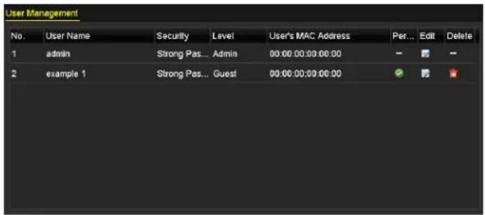
text_image
User Management No. User Name Security Level User's MAC Address Per... Edit Delete 1 admin Strong Pas... Admin 00:00:00:00:00:00 - - - 2 example 1 Strong Pas... Guest 00:00:00:00:00:00 - - -Figure 250, Added ...ser •isted in ...ser Management Interface
- Assign permissions for the added user.
1) ™elect the user from the list and then click √ to enter the Permission Settings interface, as shown in 0.
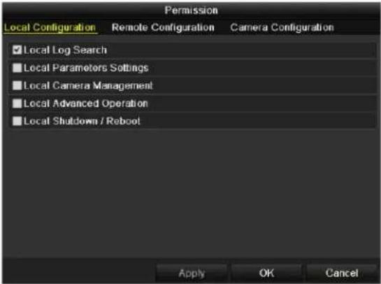
text_image
Permission Local Configuration Remote Configuration Camera Configuration ✓ Local Log Search ■ Local Parameters Settings ■ Local Camera Management ■ Local Advanced Operation ■ Local Shutdown / Reboot Apply OK CancelFigure 251, ...ser Permission™ettings Interface
2) ™et the operating permissions for •ocal 'onfiguration, Remote 'onfiguration, and 'amera 'onfiguration for the user.
- Local Configuration
- •ocal •og ™earch” ™searching and viewing logs and system information of device.
- •ocal Parameters™ettings" 'onfiguring parameters, restoring factory default parameters, and importing/exporting configuration files.
- •ocal 'amera Management" Enable and disable analog camera(s). Add, delete, and edit network camera(s). ™ supported by the HD-R ™eries.
- "local Advanced Operation" Operating HDD management (initializing HDD, setting HDD property), upgrading system firmware.
- •ocal ™hutdown /Reboot" ™hutting down or rebooting the device.
- Remote Configuration
- Remote •og ™search" Remotely view logs that are saved on the device.
- Remote Parameters™ettings" Remotely configure parameters, restore factory default parameters, and import/export configuration files.
- Remote 'amera Management" Remotely enable and disable analog camera(s), and add, delete, and edit network camera(s). ™ supported by the HD-R ™eries.
- Remote ™erial Port 'ontrol" 'onfigure settings for R™-485 port.
- Remote -ideo Output 'ontrol" ™end remote control panel signal.
- Two-way Audio" Realize two-way radio between the remote client and the device.
- Remote Alarm 'ontrol" Remotely arm (notify alarm and exception message to the remote client) and control the alarm output.
- Remote Advanced Operation" Remotely operate HDD management (initialize HDD, set HDD property), upgrade system firmware.
- Remote ™ shutdown/Reboot™ Remotely shut down or reboot the device.
- Camera Configuration
- Remote •ive -iew" Remotely view live video of the selected camera(s).
- •ocal Manual Operation" •ocally start/stopp manual recording, picture capture, and alarm output of the selected camera(s).
- Remote Manual Operation" Remotely start/stop manual recording, picture capture, and alarm output of the selected camera(s).
- •ocal Playback" •ocally play back recorded files of the selected camera(s).
- Remote Playback" Remotely play back recorded files of the selected camera(s).
- •ocal PTZ 'ontrol" •ocally control PTZ movement of the selected camera(s).
- Remote PTZ 'ontrol" Remotely control PTZ movement of the selected camera(s).
- •ocal –ideo Export" •ocally export recorded files of the selected camera(s).

NOTE
-ocal 'amera Management is provided for IP cameras only.
- 'lick OK to save the settings and exit.
15.4.2 Deleting a User
- Enter the User Management interface, Menu > 'onfiguration > ...ser.
- ™elect the user to be deleted from the list, as shown in 0.
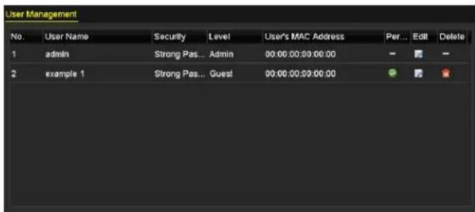
text_image
User Management No. User Name Security Level User's MAC Address Per... Edit Delete 1 admin Strong Pass... Admin 00:00:00:00:00:00 - - - 2 example 1 Strong Pass... Guest 00:00:00:00:00:00 - - -Figure 252, ...ser •ist
- 'lick to delete the selected user account.
15.4.3 Editing a User
For the added user account, you can edit the parameters.
- Enter the User Management interface, Menu > 'onfiguration > ...ser.
- ™elect the user to be edited from the list, as shown in 0.
- 'lick to enter the Edit User interface, as shown in 0.
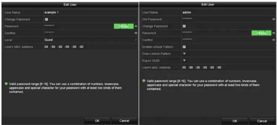
text_image
Edit User User Name example 1 Change Password Password ******** Confirm ******** Level Guest Users MAC Address 00 :00 :00 :00 :00 :00 Valid password range [8-16]. You can use a combination of numbers, lowercase, uppercase and special character for your password with at least two kinds of them contained. OK Cancel Edit User User Name admin Old Password ******** Change Password ✓ Password ******** Confirm ******** Enable Unlock Pattern ✓ Draw Unlock Pattern ✓ Export GUID ✓ Users MAC Address 00 :00 :00 :00 :00 :00 Valid password range [8-16]. You can use a combination of numbers, lowercase, uppercase and special character for your password with at least two kinds of them contained. OK CancelFigure 253, Edit ...ser Interface
-
Edit the corresponding parameters.
-
Operator and Guest – √ou can edit the user information, including user name, password, permission level, and MA' address. 'heck the Change Password checkbox to change the password, and input the new password in the Password and 'onfirm text fields. A strong password is recommended.
- √dmin – √ou are allowed only to edit the password and MA' address. 'heck the 'hange Password checkbox to change the password, and input the correct old password and the new password in the of Password and 'onfirm text fields.

WARNING
STRO™G P√SSWORD RECOMME™DED – We highly recommend you create a strong password of your own choosing (using a minimum of eight characters, including at least three of the following categories" upper case letters, lower case letters, numbers, and special characters) in order to increase the security of your product. We also recommend that you reset your password regularly. Especially in a high security system, resetting the password monthly or weekly can better protect your product.

NOTE
Hold down 📋nd to see clear text of the password. Release the mouse and the password becomes hidden.
- Edit the unlock pattern for the admin user account.
1) 'heck the Enable Unlock Pattern checkbox to enable the use of an unlock pattern when logging in to the device.
2) ...se the mouse to draw a pattern among the nine dots on the screen. Release the mouse when the pattern is done.
3) 'onfirm the pattern again with the mouse.

text_image
Set Unlock Pattern Draw the unlock pattern first.Figure 254, ™et ...nlock Patter for Admin ...ser
-
(Optional) 'lick after Draw Unlock -attern to modify the pattern.
-
(Optional) 'lick after Export GUID to pop up the Reset Password interface.'lick Export to export G...ID to the ...TM B flash drive for retrieving the forgotten password.
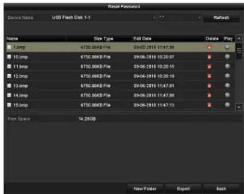
text_image
Reset Password Device Name: USB Flash Disk 1-1 Refresh Name Size Type Edit Date Order Play 13.bmp 6750.00KB File 09-05-2016 11:47:54 10.bmp 6750.00KB File 09-06-2016 10:20:57 11.bmp 6750.00KB File 09-06-2016 10:20:15 12.bmp 6750.00KB File 09-06-2016 10:20:19 13.bmp 6750.00KB File 09-06-2016 11:47:51 14.bmp 6750.00KB File 09-06-2016 11:47:58 15.bmp 6750.00KB File 09-06-2016 11:47:53 Free Space 14.28GB New Folder Export BackFigure 255, Export G...ID

NOTE
Enter the correct old admin password before exporting G...ID.
- 'lick 'K to save the settings and exit from the menu.
". (Optional) For an 'perator or Guest user account, you can also click on the User Management interface to edit the permissions.
Chapter •6 √ppendix
•6.• Glossary
- Dual-Stream: Dual-stream is a technology used to record high resolution video locally while transmitting a lower resolution stream over the network. The two streams are generated by the D–R, with the main stream having a maximum resolution of 1080P and the sub-stream having a maximum resolution of 'IF.
- DV": Acronym for Digital –ideo Recorder. A D–R is device that is able to accept video signals from analog cameras, compress the signal and store it on its hard drives.
- HDD: Acronym for Hard Disk Drive. A storage medium which stores digitally encoded data on platters with magnetic surfaces.
- DHC-: Dynamic Host 'onfiguration Protocol (DH'P) is a network application protocol used by devices (DH'P clients) to obtain configuration information for operation in an Internet Protocol network.
- HTT-: Acronym for Hypertext Transfer Protocol. A protocol to transfer hypertext request and information between servers and browsers over a network
- —oE: PPPoE, Point-to-Point Protocol over Ethernet, is a network protocol for encapsulating Point-to-Point Protocol (PPP) frames inside Ethernet frames. It is used mainly with AD™• services where individual users connect to the AD™• transceiver (modem) over Ethernet and in plain Metro Ethernet networks.
- DD™S: Dynamic DN™ is a method, protocol, or network service that provides the capability for a networked device, such as a router or computer system using the Internet Protocol ™uite, to notify a domain name server to change, in real time (ad-hoc) the active DN™ configuration of its configured hostnames, addresses or other information stored in DN™.
- Hybrid DV": A hybrid D-R is a combination of a D-R and N-R.
- TMT-: Acronym for Network Time Protocol. A protocol designed to synchronize the clocks of computers over a network.
- ™TSC: Acronym for National Television ™ystem 'ommittee. NT™' is an analog television standard used in such countries as the ...nited ™tates and Japan. Each NT™' signal frame contains 525 scan lines at 60 Hz.
- TMV": Acronym for Network –ideo Recorder. An N–R can be a P'-based or embedded system used for centralized management and storage for IP cameras, IP Domes and other D–Rs.
- -√L: Acronym for Phase Alternating •ine. PA• is also another video standard used in broadcast televisions systems in large parts of the world. PA• signal contains 625 scan lines at 50Hz.
- -TZ: Acronym for Pan, Tilt, Zoom. PTZ cameras are motor driven systems that allow the camera to pan left and right, tilt up and down and zoom in and out.
- USB: Acronym for ...niversal ^TM serial Bus. ... ^TM B is a plug-and-play serial bus standard to interface devices to a host computer.
16.2 Troubleshooting
- ^TM o image displayed on the monitor after the device is starting up normally
- Possible Causes
* No VGA or HDMI connections
* Connection cable is damaged
* Input mode of the monitor is incorrect
- Possible Fixes
- Verify the device is connected with the monitor via HDMI or VGA cable. If not, connect the device to the monitor and reboot.
- Verify the connection cable is good. If there is still no image display on the monitor after rebooting, check if the connection cable is good, and change a cable to connect again.
- Verify Input mode of the monitor is correct. Check the input mode of the monitor matches the output mode of the device (e.g., if the DVR output mode is HDMI, the monitor input mode must be HDMI). If not, please modify the input mode of monitor.
- Check if the fault is solved by the step 1 to step 3. If it is solved, finish the process. If not, contact our company.
- There is a beeping sound after a new device starts up
- Possible Reasons
* No HDD is installed in the device
* The installed HDD has not been initialized
* The installed HDD is not compatible with the device or is defective
- Possible Fixes
- Verify at least one HDD is installed in the device. If not, install a compatible HDD.

Refer to the “≤uick Operation Guide” for HDD installation steps.
- If you do not want to install an HDD, select "Menu > Configuration > Exceptions," and uncheck the "HDD Error" Audible Warning checkbox.
- Verify the HDD is initialized by selecting "Menu > HDD > General." If the HDD status is "...initialized," check the corresponding HDD checkbox and click Init.
- Verify the HDD is detected and is in good condition by selecting "Menu > HDD > General." If the HDD is not detected or the status is "Abnormal," replace the dedicated HDD according to the requirement.
- Check if the fault is solved. If it is solved, finish the process. If not, contact our company.
• Live View stuck when video outputs locally
- Possible Reasons
* The frame rate has not reached the real-time frame rate
- Possible Fixes
- Check the parameters of Main ^TM stream (Continuous) and Main ^TM stream (Event). ^TM elect “Menu > Record > Parameters > Record,” and set the resolution of Main ^TM stream (Event) the same as Main ^TM stream (Continuous).
- Verify the frame rate is real-time frame rate. ™elect "Menu > Record > Parameters > Record," and set the Frame Rate to Full Frame.
- Check if the fault is solved. If it is solved, finish the process. If not, contact our company.
- When using the device to get Live View audio, there is no sound, there is too much noise, or the volume is too low
- Possible Reasons
* Cable between the pickup and camera is not connected well; impedance mismatches or incompatible
* The stream type is not set to "Video & Audio"
- Possible Fixes
- Verify the cable between the pickup and camera is connected well; impedance matches is and compatible.
- Verify the setting parameters are correct. ™elect "Menu > Record > Parameters > Record," and set the ™tream Type as "Audio & Video."
- Check if the fault is solved. If it is solved, finish the process. If not, contact our company.
- The image gets stuck when the DVR is playing back single or multi-channel cameras
- Possible Reasons
* The frame rate is not the real-time frame rate
* The DVR supports up to 16-channel synchronized playback at 4CIF resolution. Frame extracting may occur during 16-channel synchronized playback at 720p resolution, which may cause image freezing.
- Possible Fixes
- Verify the frame rate is real-time frame rate. ^TM elect "Menu > Record > Parameters > Record," and set the Frame Rate to "Full Frame."
- Verify the hardware can support the playback. Reduce the number of playback channels. ^TM elect "Menu > Record > Encoding > Record," and set the resolution and bitrate to a lower level.
- Reduce the number of local playback channels. ™elect "Menu > Playback," and uncheck unnecessary channels checkboxes.
- Check if the fault is solved. If it is solved, finish the process. If not, contact our company.
- ^TM o record file found in the device's local HDD, and a “ ^TM o record file found” prompt pops up when you search the record files
- Possible Reasons
* The time setting of system is incorrect
* The search condition is incorrect
* The HDD is error or not detected
- Verify the system time setting is correct. ™elect "Menu > Configuration > General > General," and verify the "™ystem Time" is correct.
- Verify the search condition is correct. ™elect "Playback," and verify the channel and time are correct.
- Verify the HDD status is normal. ^TM elect "Menu > HDD > General" to view the HDD status, and verify the HDD is detected and can be read and written normally.
- Check if the fault is solved. If it is solved, finish the process. If not, contact our company.