DS-7616HUHI-F2/N - Dictaphone Hikvision - Free user manual and instructions
Find the device manual for free DS-7616HUHI-F2/N Hikvision in PDF.


| Product Type | Hybrid DVR (Analog + IP) |
| Model | DS-7616HUHI-F2/N |
| Brand | Hikvision |
| Video Channels | 16 channels (analog) + up to 16 IP cameras |
| Recording Resolution | Up to 5 MP (analog) / 8 MP (IP) |
| Compression | H.265+ / H.265 / H.264+ / H.264 |
| Audio | 16-channel audio input, 1-channel audio output |
| Storage | 2 SATA HDD bays (up to 10 TB each) |
| Power Supply | 100-240V AC, 50/60 Hz, 30W (without HDD) |
| Dimensions (W x D x H) | 380 x 320 x 48 mm |
| Weight | Approx. 2.5 kg (without HDD) |
| Operating Temperature | -10°C to +55°C |
| Network Interface | 2 x RJ45 10/100/1000 Mbps |
| USB Ports | 2 x USB 2.0, 1 x USB 3.0 |
| Alarm I/O | 16 inputs / 4 outputs |
| Main Functions | Real-time recording, motion detection, remote viewing, playback, backup, PTZ control |
| Maintenance | Regular HDD health check, firmware updates via network, clean dust from vents |
| Safety | CE, FCC, RoHS compliant; surge protection |
| Spare Parts | Power adapter, remote control, mouse, SATA cables (HDDs sold separately) |
| Repairability | Modular design: HDD, fan, power supply easily replaceable |
| General Information | Supports HDTVI/AHD/CVI/CVBS analog cameras; IP cameras up to 8MP; PoE optional via add-on module |
Frequently Asked Questions - DS-7616HUHI-F2/N Hikvision
User questions about DS-7616HUHI-F2/N Hikvision
0 question about this device. Answer the ones you know or ask your own.
Ask a new question about this device
Download the instructions for your Dictaphone in PDF format for free! Find your manual DS-7616HUHI-F2/N - Hikvision and take your electronic device back in hand. On this page are published all the documents necessary for the use of your device. DS-7616HUHI-F2/N by Hikvision.
USER MANUAL DS-7616HUHI-F2/N Hikvision
natural_image
Abstract geometric design with red diamonds, gray squares, and a white globe icon (no text or symbols)Digital Video Recorder
User Manual
UD03161B
User Manual
COPYRIGHT © 2016 Hangzhou Hikvision Digital Technology Co., Ltd.
ALL RIGHTS RESERVED.
Any and all informaon, including, among others, wordings, pictures, graphs are the properes of Hangzhou Hikvision Digital Technology Co., Ltd. or its subsidiaries (hereinaer referred to be "Hikvision"). This user manual (hereinaer referred to be "the Manual") cannot be reproduced, changed, translated, or distributed, parally or wholly, by any means, without the prior written permission of Hikvision. Unless otherwise spulated, Hikvision does not make any warranties, guarantees or representaons, express or implied, regarding to the Manual.
About this Manual
This Manual is applicable to Turbo HD Digital Video Recorder (DVR).
The Manual includes instrucons for using and managing the product. Pictures, charts, images and all other informaon hereinaer are for descripon and explanaon only. The informaon contained in the Manual is subject to change, without noce, due to rmware updates or other reasons. Please nd the latest version in the company website (hp://overseas.hikvision.com/en/).
Please use this user manual under the guidance of professionals.
Trademarks Acknowledgement
HIKVISION and other Hikvision's trademarks and logos are the properes of Hikvision in various jurisdicons. Other trademarks and logos menoned below are the properes of their respective owners.
Legal Disclaimer
TO THE MAXIMUM EXTENT PERMITTED BY APPLICABLE LAW, THE PRODUCT DESCRIBED, WITH ITS HARDWARE, SOFTWARE AND FIRMWARE, IS PROVIDED "AS IS", WITH ALL FAULTS AND ERRORS, AND HIKVISION MAKES NO WARRANTIES, EXPRESS OR IMPLIED, INCLUDING WITHOUT LIMITATION, MERCHANTABILITY, SATISFACTORY QUALITY, FITNESS FOR A PARTICULAR PURPOSE, AND NON-INFRINGEMENT OF THIRD PARTY. IN NO EVENT WILL HIKVISION, ITS DIRECTORS, OFFICERS, EMPLOYEES, OR AGENTS BE LIABLE TO YOU FOR ANY SPECIAL, CONSEQUENTIAL, INCIDENTAL, OR INDIRECT DAMAGES, INCLUDING, AMONG OTHERS, DAMAGES FOR LOSS OF BUSINESS PROFITS, BUSINESS INTERRUPTION, OR LOSS OF DATA OR DOCUMENTATION, IN CONNECTION WITH THE USE OF THIS PRODUCT, EVEN IF HIKVISION HAS BEEN ADVISED OF THE POSSIBILITY OF SUCH DAMAGES.
REGARDING TO THE PRODUCT WITH INTERNET ACCESS, THE USE OF PRODUCT SHALL BE WHOLLY AT YOUR OWN RISKS. HIKVISION SHALL NOT TAKE ANY RESPONSIBILITES FOR ABNORMAL OPERATION, PRIVACY LEAKAGE OR OTHER DAMAGES RESULTING FROM CYBER ATTACK, HACKER ATTACK, VIRUS INSPECTION, OR OTHER INTERNET SECURITY RISKS; HOWEVER, HIKVISION WILL PROVIDE TIMELY TECHNICAL SUPPORT IF REQUIRED.
SURVEILLANCE LAWS VARY BY JURISDICTION. PLEASE CHECK ALL RELEVANT LAWS IN YOUR JURISDICTION BEFORE USING THIS PRODUCT IN ORDER TO ENSURE THAT YOUR USE CONFORMS THE APPLICABLE LAW. HIKVISION SHALL NOT BE LIABLE IN THE EVENT THAT THIS PRODUCT IS USED WITH ILLEGITIMATE PURPOSES.
IN THE EVENT OF ANY CONFLICTS BETWEEN THIS MANUAL AND THE APPLICABLE LAW, THE LATER PREVAILS.
Regulatory Informaon
FCC Informaon
Please take aenon that changes or modicaon not expressly approved by the party responsible for compliance could void the user's authority to operate the equipment.
FCC compliance: This equipment has been tested and found to comply with the limits for a Class A digital device, pursuant to part 15 of the FCC Rules. These limits are designed to provide reasonable protecon against harmful interference when the equipment is operated in a commercial environment. This equipment generates, uses, and can radiate radio frequency energy and, if not installed and used in accordance with the instrucon manual, may cause harmful interference to radio communicaons. Operaon of this equipment in a residential area is likely to cause harmful interference in which case the user will be required to correct the interference at his own expense.
FCC Conditions
This device complies with part 15 of the FCC Rules. Operaon is subject to the following two conditions:
- This device may not cause harmful interference.
- This device must accept any interference received, including interference that may cause undesired operaon.
EU Conformity Statement

This product and - if applicable - the supplied accessories too are marked with "CE" and comply therefore with the applicable harmonized European standards listed under the EMC Direcve 2014/30/EU, the LVD Direcve 2014/35/EU, the RoHS Direcve 2011/65/EU.

2012/19/EU (WEEE direcve): Products marked with this symbol cannot be disposed of as unsorted municipal waste in the European Union. For proper recycling, return this product to your local supplier upon the purchase of equivalent new equipment, or dispose of it at designated collecon points. For more informaon see: www.recyclethis.info

2006/66/EC (baery direcve): This product contains a baery that cannot be disposed of as unsorted municipal waste in the European Union. See the product documentaon for speci baery informaon. The baery is marked with this symbol, which may include leering to indicate cadmium (Cd), lead (Pb), or mercury (Hg). For proper recycling, return the baery to your supplier or to a designated collecon point. For more informaon see: www.recyclethis.info
Industry Canada ICES-003 Compliance
This device meets the CAN ICES-3 (A)/NMB-3(A) standards requirements.
Applicable Models
This manual is applicable to the models listed in the following table.
| Series | Model |
| DS-7100HGHI-F1/N | DS-7104HGHI-F1/NDS-7108HGHI-F1/NDS-7116HGHI-F1/N |
| DS-7200HGHI-F1/N | DS-7204HGHI-F1/NDS-7208HGHI-F1/NDS-7216HGHI-F1/N |
| DS-7100HGHI-E1 | DS-7104HGHI-E1DS-7108HGHI-E1DS-7116HGHI-E1 |
| DS-7200HGHI-E1 | DS-7204HGHI-E1DS-7208HGHI-E1DS-7216HGHI-E1 |
| DS-7200HGHI-E2 | DS-7208HGHI-E2DS-7216HGHI-E2 |
| DS-7100HGHI-F1 | DS-7104HGHI-F1DS-7108HGHI-F1DS-7116HGHI-F1 |
| DS-7200HGHI-F1 | DS-7204HGHI-F1DS-7208HGHI-F1DS-7216HGHI-F1 |
| DS-7200HGHI-F2 | DS-7208HGHI-F2DS-7216HGHI-F2 |
| DS-7200HQHI-F1/N | DS-7204HQHI-F1/NDS-7208HQHI-F1/NDS-7216HQHI-F1/N |
| DS-7200HQHI-F2/N | DS-7208HQHI-F2/NDS-7216HQHI-F2/N |
| DS-7100HQHI-F1/N | DS-7104HQHI-F1/NDS-7108HQHI-F1/NDS-7116HQHI-F1/N |
| DS-7300HQHI-F4/N | DS-7304HQHI-F4/NDS-7308HQHI-F4/NDS-7316HQHI-F4/N |
| DS-8100HQHI-F8/N | DS-8104HQHI-F8/NDS-8108HQHI-F8/NDS-8116HQHI-F8/N |
| DS-7200HUHI-F1/N | DS-7204HUHI-F1/NDS-7208HUHI-F1/N |
| DS-7200HUHI-F2/N | DS-7204HUHI-F2/NDS-7208HUHI-F2/NDS-7216HUHI-F2/N |
| DS-7600HUHI-F/N | DS-7604HUHI-F1/NDS-7608HUHI-F2/NDS-7616HUHI-F2/N |
| DS-7300HUHI-F4/N | DS-7304HUHI-F4/NDS-7308HUHI-F4/NDS-7316HUHI-F4/N |
| DS-8100HUHI-F8/N | DS-8104HUHI-F8/NDS-8108HUHI-F8/NDS-8116HUHI-F8/N |
| DS-9000HUHI-F8/N | DS-9004HUHI-F8/NDS-9008HUHI-F8/NDS-9016HUHI-F8/N |
| DS-9000HUHI-F16/N | DS-9008HUHI-F16/NDS-9016HUHI-F16/N |
Symbol Conventions
The symbols that may be found in this document are dened as follows.
| Symbol | Description |
 NOTE NOTE | Provides additional informaon to emphasize or supplement important points of the main text. |
 WARNING WARNING | Indicates a potenally hazardous situaon, which if not avoided, could result in equipment damage, data loss, performance degradaon, or unexpected results. |
 DANGER DANGER | Indicates a hazard with a high level of risk, which if not avoided, will result in death or serious injury. |
Safety Instructions
- Proper conguraon of all passwords and other security sengs is the responsibility of the installer and/or end-user.
- In the use of the product, you must be in strict compliance with the electrical safety regulaons of the naon and region. Please refer to technical specicaons for detailed informaon.
- Input voltage should meet both the SELV (Safety Extra Low Voltage) and the Limited Power Source with 100 to 240 VAC or 12 VDC according to the IEC60950-1 standard. Please refer to technical speciaons for detailed informaon.
- Do not connect several devices to one power adapter as adapter overload may cause over-heang or a re hazard.
- Please make sure that the plug is rmly connected to the power socket.
- If smoke, odor or noise rise from the device, turn off the power at once and unplug the power cable, and then please contact the service center.
Preventive and Cautionary Tips
Before connecng and operang your device, please be advised of the following ps:
● Ensure unit is installed in a well-venlated, dust-free environment.
- Unit is designed for indoor use only.
- Keep all liquids away from the device.
● Ensure environmental conditions meet factory speciaons.
- Ensure unit is properly secured to a rack or shelf. Major shocks or jolts to the unit as a result of dropping it may cause damage to the sensitive electronics within the unit.
- Use the device in conjuncon with an UPS if possible.
● Power down the unit before connecng and disconnectg accessories and peripherals.
● A factory recommended HDD should be used for this device.
- Improper use or replacement of the battery may result in hazard of explosion. Replace with the same or equivalent type only. Dispose of used baeries according to the instrucons provided by the baery manufacturer.
1.1 Product Key Features
General
- Connectable to HDTV1 and analog cameras;
● Support HIKVISION-C protocol for connecng camera over coax; - Connectable to AHD cameras (-F series DVR);
- Connectable to HDCVI cameras;
- Connectable to IP cameras;

NOTE
The IP camera conncon is not supported by DS-7100 series DVR.
● Each channel supports dual-stream. And sub-stream supports up to WD1 resoluon;
● The main stream of HGHI models support up to 720p resoluon;
- The main stream of HQHI series support up to 3 MP resolution for the rst channel of DVR with 4-ch video inputs, the rst 2 channels of DVR with 8-ch video inputs and the rst 4 channels of DVR with 16-ch video inputs;
- For HQHI and DS-7200HUHI-F/N series DVR, if the 3 MP camera is connected to the channel which supports up to 1080p signal input, it will switch to 1080p signal input. When the 3 MP signal is switched to 1080p signal, the PAL will be switched to 1080p/25Hz, and the NTSC will be switched to 1080p/30Hz;
- The main stream of DS-7200/7300/7600/8100/9000HUHI-F/N series support up to 3 MP resolution of all channels;
- For HGHI-F series DVR, 1080p lite mode is applicable to all the channels;
- Independent conguraon for each channel, including resoluon, frame rate, bit rate, image quality, etc.;
- Encoding for both video stream and video & audio stream; audio and video synchronizaon during composite stream encoding;
● Support enabling H.265+ (for DS-7300/8100/9000HUHI-F/N series)/H.264+ to ensure high video quality with lowered bitrate;
● One-key enable or disable H.264+ for -F series DVR;
● Support conguring night to day sensitivity, day to night sensitivity and IR light brightness for the connected analog cameras supporting these parameters;
● Watermark technology.
Local Monitoring
- HDMI output at up to 4K (3840 × 2160) resoluon for DS-7116HQHI-F1/N, DS-7216HQHI-F1/N, DS-7216HQHI-F2/N, DS-7208HUHI-F1/N, DS-7208HUHI-F2/N, DS-7216HUHI-F2/N, DS-7608HUHI-F2/N, DS-7616HUHI-F2/N, DS-7300HQHI-F4/N and DS-8100HQHI-F8/N;
- For DS-7608/7616HUHI-F/N and DS-7300/8100HQHI-F/N series DVR, the HDMI and VGA interfaces can be congured to be simultaneous or independent. Up to 1920 × 1080/60 Hz resoluon is supported for VGA output and up to 4K (3840 × 2160)/30 Hz resoluon is supported for HDMI output.
- For DS-7300/8100/9000HUHI-F/N series, there are two HDMI interfaces of which the HDMI1 and VGA interfaces share simultaneous output. For HDMI1/VGA output, up to 1920 × 1080 resolution is supported. For HDMI2 output, up to 4K (3840 × 2160) resolution is supported;
● 1/4/6/8/9/16/25/36 screen live view is supported, and the display sequence of screens is adjustable;

For DS-7300/8100/9000HUHI-F/N series DVR, if the sum of the analog and IP channels exceeds 25, up to 32-window division mode is supported for the VGA/HDMI1 output.
● Live view screen can be switched in group and manual switch and automac cycle live view are also provided, the interval of automac cycle can be adjusted;
- For –F series DVR, CVBS output only serves as the aux output or live view output.
- Quick seng menu is provided for live view;
● The selected live view channel can be shielded;
- Moon detecon, video-tampering detecon, video excepon alarm, video loss alarm and VCA alarm funcons;
- For DS-7300/8100/9000HUHI-F/N series DVR, 1-ch analog camera supports people counting and heat map funcons;
- DS-7200/7300/8100/9000HUHI-F/N series DVR support VCA (line crossing detecon and intrusion detecon) of all channels. DS-7600HUHI-F/N series DVR support 2-ch VCA (line crossing detecon and intrusion detecon). HQHI series DVR excluding 7100 series support 2-ch VCA (line crossing detecon and intrusion detecon). For the analog channels, the line crossing detecon and intrusion detecon conict with other VCA detecon such as sudden scene change detecon, face detecon and vehicle detecon and heat map or people counng funcons. You can only enable one funcon;
- DS-7208/7216HUHI-F/N series DVR supports enhanced VCA mode to enable all-channel line crossing detecon and intrusion detecon and disable 2K/4K output resoluon. Aer you enable it, you can also disable it and the line crossing detecon and intrusion detecon will be supported by 2-ch only;
- Privacy mask;
- Several PTZ protocols (including Omnicast VMS of Genetec) supported; PTZ preset, patrol and paern;
- Zooming in/out by clicking the mouse and PTZ tracing by dragging mouse.
HDD Management
● Each disk with a maximum of 8 TB storage capacity for DS-9000HUHI-F16/N series DVR and 6 TB for other models;
- 8 network disks (8 NAS disks, 8 IP SAN disks or n NAS disks + m IP SAN disks (n+m ≤ 8)) can be connected;
● Remaining recording me of the HDD can be viewed;
● Support cloud storage;

Cloud storage is only applicable to HQHI-F/N and HUHI-F/N series DVR.
● S.M.A.R.T. and bad sector detecon;
- HDD sleeping funcon;
- HDD property: redundancy, read-only, read/write (R/W);
- HDD group management;
- HDD quota management; different capacity can be assigned to different channels.
- For DS-7300/8100/9000HUHI-F/N series, hot-swappable HDD supporting RAID0, RAID1, RAID5, RAID 6 and RAID10 storage scheme, and can be enabled and disabled on your demand. And 16 arrays can be congured.
Recording, Capture and Playback

Capture is supported by DS-7300/8100/9000HUHI-F/N series DVR only.
● Holiday recording schedule conguraon;
● Cycle and non-cycle recording modes;
● Normal and event video encoding parameters;
- Mulple recording types: manual, connuous, alarm, moon, moon | alarm, moon & alarm and Event;
● Support POS triggered recording for DS-7300/8100HQHI-F/N and DS-7300/8100/9000HUHI-F/N series DVR;
● 8 recording me periods with separated recording types;
● Support Channel-Zero encoding;
● Main stream and sub-stream congorable for simultaneous recording;
- Pre-record and post-record for moon detecon triggered recording, and pre-record me for schedule and manual recording;
- Searching record les and captured pictures by events (alarm input/moon detecon);
- Customizaon of tags, searching and playing back by tags;
- Locking and unlocking of record les;
- Local redundant recording and capture;
- For -F series DVR, when HDTVI, AHD, or HDCVI input is connected, the informaon including the resoluon and frame rate will be overlaid on the boom right corner of the live view for 5 seconds. When CVBS input is connected, the informaon such as NTSC or PAL will be overlaid on the boom right corner of the live view for 5 seconds.
- Searching and playing back record les by camera number, recording type, start me, end me, etc.;
● Smart playback to go through less eecve informaon; - Main stream and sub-stream selectable for local/remote playback;
- Zooming in for any area when playback;
- Mul-channel reverse playback;
● Supports pause, fast forward, slow forward, skip forward, and skip backward when playback, locang by dragging the mouse on the progress bar;
● 4/8/16-ch synchronous playback;
● Manual capture, connuous capture of video images and playback of captured pictures.
Backup
● Export data by a USB, and SATA device;
● Export video clips when playback;
● Management and maintenance of backup devices.
Alarm and Excepon
- Congurable arming me of alarm input/output;
- Alarm for video loss, moon detecon, video tampering, abnormal signal, video input/recording resoluon mismatch, illegal login, network disconnected, IP conicon, record/capture excepon, HDD error, and HDD full, etc.;
- Alarm triggers full screen monitoring, audio alarm, nofying surveillance center, sending email and alarm output;
● VCA detecon alarm is supported;

DS-7100 does not support VCA alarm.
● Support POS triggered alarm;
● Support coaxial alarm;
● Automac restore when system is abnormal.
Other Local Funcons
● Manual and automac video quality diagnoses;
- Operable by mouse and remote control;
- Three-level user management; admin user can create many operang account and define their operang permission, which includes the permission to access any channel;
● Completeness of operaon, alarm, excepons and log wring and searching;
● Manually triggering and clearing alarms; - Imporng and exporng of conguraon le of devices;
● Geng cameras type informaon automacally; - Unlock pattern for device login for the admin;
● Clear-text password available;
● GUID le can be exported for password reseng.
Network Funcons
- 2 self-adapve 10M/100M/1000M network interfaces for DS-8100HQHI-F/N and DS-7300/8100/9000HUHI-F/N series. For DS-8100HQHI-F/N series, three working modes are congorable: mul-address, load balance, network fault tolerance. For DS-7300/8100/9000HUHI-F/N series, only mul-address and network fault tolerance are congorable. 1 self-adapve 10M/100M/1000M network interface or 1 self-adapve 10M/100Mbps network interface provided for other models;
- IPv6 is supported;
- TCP/IP protocol, PPPoE, DHCP, DNS, DDNS, NTP, SADP, SMTP, NFS, iSCSI, UPnP™ and HTTPS are supported;
● Extranet access by HiDDNS;
● Support access by Hik Cloud P2P;
● TCP, UDP and RTP for unicast;
● Auto/Manual port mapping by UPnPTM; - Remote search, playback, download, locking and unlocking the record les, and downloading les broken transfer resume;
- Remote parameters setup; remote import/export of device parameters;
- Remote viewing of the device status, system logs and alarm status;
● Remote keyboard operaon;
● Remote HDD formang and program upgrading;
● Remote system restart and shutdown;
● Support upgrading via remote FTP server;
● RS-485 transparent channel transmission; - Alarm and excepon informaon can be sent to the remote host;
● Remotely start/stop recording;
● Remotely start/stop alarm output; - Remote PTZ control;
● Remote JPEG capture;
● Two-way audio and voice broadcasts;
- Output bandwidth limit congorable for -F series DVR;
- Embedded WEB server;
- For -F series DVR, if DHCP is enabled, you can enable DNS DHCP or disable it and edit the Preferred DNS Server and Alternate DNS Server.
Development Scalability
- SDK for Windows and Linux system;
● Source code of applicaon soware for demo;
● Development support and training for applicaon system.
Table of Contents
1.1 Product Key Features ....7
Chapter 1 Introduction....20
1.1 Front Panel....20
1.2 IR Remote Control Operaons....37
1.3 USB Mouse Operaon 40
1.4 Input Method Descripon 41
1.5 Rear Panel 42
Chapter 2 Getting Started ....52
2.1 Starng Up and Shung Down the DVR 52
2.2 Acvang the Device 53
2.3 Using the Unlock Pattern for Login 55
2.3.1 Conguring the Unlock Paern ....55
2.3.2 Logging in via Unlock Pattern....57
2.4 Basic Conguraon in Startup Wizard....59
2.4.1 Conguring the Signal Input Wizard....59
2.4.2 Using the Wizard for Basic Conguraon....59
2.5 Login and Logout 65
2.5.1 User Login 65
2.5.2 User Logout....67
2.6 Adding and Connecng the IP Cameras 68
2.6.1 Acvang the IP Camera....68
2.6.2 Adding the Online IP Camera....70
2.6.3 Eding the Connected IP Camera 73
2.7 Conguring the Signal Input Channel 75
Chapter 3 Live View ....77
3.1 Introduction of Live View 77
3.2 Operations in Live View Mode ....77
3.2.1 Using the Mouse in Live View....79
3.2.2 Switching Main/Aux Output 81
3.2.3 Quick Seng Toolbar in Live View Mode 82
3.3 Channel-Zero Encoding....84
3.4 Adjusting Live View Settings 85
3.5 Manual Video Quality Diagnostics....86
Chapter 4 PTZ Controls ....88
4.1 Conguring PTZ Setngs 88
4.2 Seng PTZ Presets, Patrols and Patterns 90
4.2.1 Customizing Presets....90
4.2.2 Calling Presets....91
4.2.3 Customizing Patrols....91
4.2.4 Calling Patrols....92
4.2.5 Customizing Paerns 93
4.2.6 Calling Paerns 94
4.2.7 Customizing Linear Scan Limit 95
4.2.8 Calling Linear Scan 96
4.2.9 One-touch Park 97
4.3 PTZ Control Panel....98
Chapter 5 Recording and Capture Settings....100
5.1 Conguring Encoding Parameters ....100
5.2 Conguring Recording and Capture Schedule 106
5.3 Conguring Moon Detecon Recording and Capture 109
5.4 Conguring Alarm Triggered Recording and Capture 111
5.5 Conguring Event Recording and Capture....112
5.6 Conguring Manual Recording and Connous Capture 114
5.7 Conguring Holiday Recording and Capture....115
5.8 Conguring Redundant Recording and Capture 117
5.9 Conguring HDD Group 119
5.10 Files Protecon....120
5.11 One-Key Enabling and Disabling H.264+ for Analog Cameras....122
5.12 Conguring 1080P Lite....124
Chapter 6 Playback....127
6.1 Playing Back Record Files....127
6.1.1 Instant Playback....127
6.1.2 Playing Back by Normal Search....127
6.1.3 Playing Back by Event Search....130
6.1.4 Playing Back by Tag 132
6.1.5 Playing Back by Smart Search....135
6.1.6 Playing Back by System Logs....138
6.1.7 Playing Back by Sub-Periods....139
6.1.8 Playing Back External File 140
6.1.9 Playing Back Pictures 141
6.2 Auxiliary Functions of Playback....142
6.2.1 Playing Back Frame by Frame 142
6.2.2 Digital Zoom....143
6.2.3 Reverse Playback of Mul-Channel 143
Chapter 7 Backup....145
7.1 Backing up Record Files....145
7.1.1 Backing up by Normal Video/Picture Search....145
7.1.2 Backing up by Event Search 147
7.1.3 Backing up Video Clips....148
7.2 Managing Backup Devices....149
Chapter 8 Alarm Settings....151
8.1 Seng Moon Detecon 151
8.2 Seng Sensor Alarms....153
8.3 Detecng Video Loss 155
8.4 Detecng Video Tampering 157
8.5 Seng All-day Video Quality Diagnoscs 158
8.6 Handling Excepons....160
8.7 Seng Alarm Response Acons....162
Chapter 9 POS Configuration....165
9.1 Conguring POS Setngs 165
9.2 Conguring Overlay Channel 170
9.3 Conguring POS Alarm....171
Chapter 10 VCA Alarm....174
10.1 Face Detecon 174
10.2 Vehicle Detecon....175
10.3 Line Crossing Detecon 177
10.4 Intrusion Detection....178
10.5 Region Entrance Detecon....180
10.6 Region Exing Detecon....181
10.7 Loitering Detecon 182
10.8 People Gathering Detecon 182
10.9 Fast Moving Detecon....182
10.10 Parking Detecon....183
10.11 Unattended Baggage Detecon....183
10.12 Object Removal Detecon....184
10.13 Audio Excepon Detecon 184
10.14 Defocus Detecon....185
10.15 Sudden Scene Change....186
10.16 PIR Alarm .... 186
Chapter 11 VCA Search....188
11.1 Face Search 188
11.2 Behavior Search....190
11.3 Plate Search 191
11.4 People Counng....192
11.5 Heat Map....193
Chapter 12 Network Settings ....195
12.1 Configuring General Settings....195
12.2 Configuring Advanced Settings 196
12.2.1 Conguring PPPoE Setngs....196
12.2.2 Conguring Hik Cloud P2P 197
12.2.3 Conguring DDNS 198
12.2.4 Conguring NTP Server 202
12.2.5 Conguring NAT 203
12.2.6 Conguring More Sengs....205
12.2.7 Conguring HTTPS Port....206
12.2.8 Conguring Email....208
12.2.9 Checking Network Trac....210
12.3 Configuring Network Detection....211
12.3.1 Tesng Network Delay and Packet Loss....211
12.3.2 Exporng Network Packet 211
12.3.3 Checking Network Status....212
12.3.4 Checking Network Stascs....213
Chapter 13 RAID....215
13.1 Conguring Array....215
13.1.1 Enable RAID 216
13.1.2 One-touch Conguraon 217
13.1.3 Manually Creang Array 218
13.2 Rebuilding Array....220
13.2.1 Automacally Rebuilding Array 221
13.2.2 Manually Rebuilding Array....221
13.3 Deleng Array 222
13.4 Checking and Eding Firmware 223
Chapter 14 HDD Management ....224
14.1 Inializing HDDs....224
14.2 Managing Network HDD....225
14.3 Managing HDD Group....228
14.3.1 Seng HDD Groups 228
14.3.2 Seng HDD Property....229
14.4 Conguring Quota Mode....230
14.5 Conguring Cloud Storage 231
14.6 Conguring Disk Clone....234
14.7 Checking HDD Status 236
14.8 Checking S.M.A.R.T Informaon 236
14.9 Detecng Bad Sector 237
14.10 Conguring HDD Error Alarms 238
Chapter 15 Camera Settings ....240
15.1 Configuring OSD Settings 240
15.2 Configuring Privacy Mask 241
15.3 Configuring Video Parameters....242
15.3.1 Conguring Image Sengs....242
15.3.2 Conguring Camera Parameters Sengs 244
Chapter 16 DVR Management and Maintenance....246
16.1 Viewing System Information 246
16.2 Searching Log Files....246
16.3 Importing/Exporting IP Camera Info 249
16.4 Importing/Exporting Configuration Files 249
16.5 Upgrading System....250
16.5.1 Upgrading by Local Backup Device 250
16.5.2 Upgrading by FTP 251
16.6 Restoring Default Settings....251
Chapter 17 Others....253
17.1 Configuring General Settings....253
17.2 Configuring RS-232 Serial Port 255
17.3 Configuring DST Settings....255
17.4 Configuring More Settings 256
17.5 Managing User Accounts 258
17.5.1 Adding a User 258
17.5.2 Deleng a User....262
17.5.3 Eding a User 262
Chapter 18 Appendix ......265
18.1 Specicaons 265
18.5 List of Compatible Hikvision IP Cameras....327
18.6 List of Compatible Third-Party IP Cameras 328
Chapter 1 Introduction
1.1 Front Panel
Front Panel 1:

Figure 1-1 Front Panel of DS-7100
Front Panel 2:

Figure 1-2 Front Panel of DS-7200HGHI
Table 1-1 Descriponon of Front Panel
| No. | Icon | Description |
| 1 |  | Turns red when DVR is powered up. |
| 2 |  | Turns red when data is being read from or wrien to HDD. |
| 3 |  | Flickers blue when network conncon is funconing properly. |
Front Panel 3:

Figure 1-3 Front Panel of DS-7200HQHI-F/N
Table 1-2 Descripon of Front Panel
| No. | Name | Function Description |
| 1 | POWER | Turns green when the power switch on the rear panel is turned on. |
| STATUS | Flickers red when data is being read from or wrien to HDD. | |
| Tx/Rx | Flickers green when network conncon is funconing properly. | |
| 2 | IR Receiver | Receiver for IR remote |
| 3 | USB Interfaces | Universal Serial Bus (USB) ports for additional devices such as USB mouse and USB Hard Disk Drive (HDD). |
Front Panel 4:
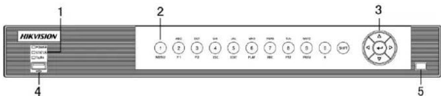
Figure 1-4 Front Panel of DS-7200HUHI-F/N and DS-7600HUHI-F/N
Table 1-3 Descripon of Front Panel
| No. | Name | Function Description | |
| 1 | POWER | Turns green when the device is running. | |
| STATUS | Flickers red when data is being read from or wrien to HDD, and turns green when the SHIFT funcon is realized. | ||
| Tx/Rx | Flickers green when network conneccon is funconing properly. | ||
| 2 | Composite Keys | SHIFT | Switches between the numeric or letter input and funcons of the composite keys. |
| 1/MENU | Enters numeral “1”;Accesses the main menu interface. | ||
| 2/ABC/F1 | Enters numeral “2”; | ||
| Enters leers “ABC”; | |||
| Uses the F1 buon to select all items in a list eld; | |||
| Turns on/o PTZ light in PTZ Control mode, and use it to zoom out the image; | |||
| Switches between main and spot video output in live view or playback mode. | |||
| 3/DEF/F2 | Enters numeral “3”; | ||
| Enters leers “DEF”; | |||
| Uses the F2 buon to change the tab pages; | |||
| Zooms in the image in PTZ control mode. | |||
| 4/GHI/ESC | Enters numeral “4”; | ||
| Enters leers “GHI”; | |||
| Exits and back to the previous menu. | |||
| 5/JKL/EDIT | Enters numeral “5”; | ||
| Enters leers “JKL”; | |||
| Deletes characters before cursor; | |||
| Checks the checkbox and select the ON/OFF switch; | |||
| Starts/stops record clipping in playback. | |||
| 6/MNO/PLAY | Enters numeral “6”; | ||
| Enters leers “MNO”; | |||
| Accesses to playback interface in Playback mode. | |||
| 7/PQRS/REC | Enters numeral “7”; | ||
| Enters leers “PQRS”; | |||
| Accesses to manual record interface; Manually enables/disables record. | |||
| 8/TUV/PTZ | Enters numeral “8”; | ||
| Enters leers “TUV”; | |||
| Accesses PTZ control interface. | |||
| 9/WXYZ/PREV | Enters numeral “9”; | ||
| Enters leers “WXYZ”; | |||
| Mul-channel display in live view. | |||
| 0/A | Enters numeral “0”; | ||
| Shis the input methods in the eding text eld.(Upper and lowercase, alphabet, symbols or numeric input). | |||
| 3 | DIRECTION | Navigates between dierent elds and items in menus. | |
| Uses the Up and Down buons to speed up and slow down the playing of video les in Playback mode.The Le and Right button will select the next and previous record les. | |||
| Cycles through channels in Live View mode. | |||
| Controls the movement of the PTZ camera in PTZ control mode. | |||
| ENTER | Conrms selecon in any of the menu modes. | ||
| Checks the checkbox. | |||
| Plays or pauses the playing of video les in Playback mode. | |||
| Advances the video by a single frame in single-frame Playback mode. | |||
| Stops/starts auto switch in Auto-switch mode. | |||
| 4 | USB Interface | Universal Serial Bus (USB) ports for additional devices such as USB mouse and USB Hard Dis Drive (HDD). | |
| 5 | IR Receiver | Receiver for IR remote control. | |
Front Panel 5:

Figure 1-5 Front Panel of DS-7300HQHI-F/N and DS-7300HUHI-F/N
Table 1-4 Descripon of Front Panel
| No. | Name | Function Description | |
| 1 | POWER | Turns green when DVR is powered up. | |
| READY | Turns green, indicang that the DVR is funconing properly. | ||
| STATUS | Turns green when device is controlled by an IR remote. | ||
| Turns red when controlled by a keyboard and purple when IR remote and keyboard is used at the same me. | |||
| ALARM | Turns red when a sensor alarm is detected. | ||
| HDD | Flickers in red when data is being read from or wrien to HDD. | ||
| Tx/Rx | Flickers in green when network conncon is funconing properly. | ||
| 2 | DVD-R/W | Slot for DVD-R/W. | |
| 3 | Composite Keys | SHIFT | Switches between the numeric or letter input and funcons of the composite keys. (Input leer or numbers when the light is out; Realize funcons when the light is red.) |
| 1/MENU | Enters numeral “1”;Accesses the main menu interface. | ||
| 2/ABC/F1 | Enters numeral “2”;Enters leers “ABC”; | ||
| The F1 buon when used in a list eld will select all items in the list; | |||
| Turns on/o PTZ light in PTZ Control mode, and use it to zoom out the image; | |||
| Switches between main and spot video output in live view or playback mode. | |||
| 3/DEF/F2 | Enters numeral “3”; | ||
| Enters letters “DEF”; | |||
| Uses the F2 buon is used to change the tab pages; | |||
| Zooms in the image in PTZ control mode. | |||
| 4/GHI/ESC | Enters numeral “4”; | ||
| Enters leers “GHI”; | |||
| Exits and back to the previous menu. | |||
| 5/JKL/EDIT | Enters numeral “5”; | ||
| Enters leers “JKL”; | |||
| Deletes characters before cursor; | |||
| Check the checkbox and select the ON/OFF switch; | |||
| Starts/stops record clipping in playback. | |||
| 6/MNO/PLAY | Enters numeral “6”; | ||
| Enters leers “MNO”; | |||
| Accesses to playback interface in Playback mode. | |||
| 7/PQRS/REC | Enters numeral “7”; | ||
| Enters leers “PQRS”; | |||
| Accesses to manual record interface; Manually enables/disables record. | |||
| 8/TUV/PTZ | Enters numeral “8”; | ||
| Enters leers “TUV”; | |||
| Accesses PTZ control interface. | |||
| 9/WXYZ/PREV | Enters numeral “9”; | ||
| Enters leers “WXYZ”; | |||
| Mul-channel display in live view. | |||
| 0/A | Enters numeral “0”; | ||
| Shis the input methods in the eding text eld. (Upper and lowercase, alphabet, symbols or numeric input). | |||
| 4 | DIRECTION | Navigates between dierent elds and items in menus. | |
| Uses the Up and Down buons to speed up and slow down the playing of video les in Playback mode. The Le and Right buon will select the next and previous record les. | |||
| Cycles through channels in Live View mode. | |||
| Controls the movement of the PTZ camera in PTZ control mode. | |||
| ENTER | Conrms selecon in any of the menu modes. | ||
| Checks the checkbox. | |||
| Plays or pauses the playing of video les in Playback mode. | |||
| Advances the video by a single frame in single-frame Playback mode. | |||
| Stops/starts auto switch in Auto-switch mode. | |||
| 5 | POWER | Power on/o switch. | |
| 6 | JOG SHUTTLE Control | Moves the acve selecon up and down in a menu. | |
| Cycles through dierent channels in live view mode. | |||
| Jumps 30s forward/backward in video les in the playback mode. | |||
| Controls the movement of the PTZ camera in PTZ control mode. | |||
| Moves the acve selecon up and down in a menu. | |||
| 7 | USB Interface | Universal Serial Bus (USB) ports for additional devices such as USB mouse and USB Hard Disk Drive (HDD). | |
| 8 | IR Receiver | Receiver for IR remote control. | |
Front Panel 6:
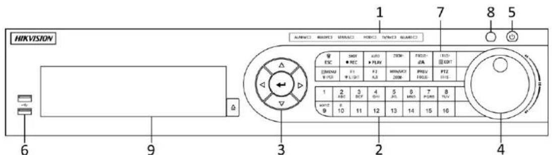
Figure 1-6 Front Panel of DS-8100HQHI-F/N and DS-8100HUHI-F/N
Table 1-5 Descripon of Front Panel
| No. | Name | Function Description | |
| 1 | Status Indicators | ALARM | Turns red when a sensor alarm is detected. |
| READY | Turns blue, indicang that the DVR is funconing properly. | ||
| STATUS | Turns blue when device is controlled by an IR remote. | ||
| Turns red when controlled by a keyboard and purple when IR remote and keyboard is used at the same me. | |||
| HDD | Flickers in red when data is being read from or wrien to HDD. | ||
| Tx/Rx | Flickers in blue when network conncon is funconing properly. | ||
| GUARD | Turns blue when the device is in armed status; a this me, an alarm is enabled when an event is detected. | ||
| Turns o when the device is unarmed. The arm/disarm status can be changed by pressing and holding on the ESC buon for more than 3 seconds in live view mode. | |||
| 2 | Alphanumeric Buons | Switches to the corresponding channel in live view or PTZ control mode. | |
| Inputs numbers and characters in edit mode. | |||
| Switches between dierent channels in playback mode. | |||
| Turns blue when the corresponding channel is recording; turns red when the channel is in network transmission status; turns pink when the channel is recording and transming. | |||
| 3 | Control Buons | DIRECTION | Navigates between dierent elds and items in menus. |
| Uses the Up and Down buons to speed up and slow down the playing of video les in Playback mode.The Le and Right buon will select the next and previous record les. | |||
| Cycles through channels in Live View mode. | |||
| Controls the movement of the PTZ camera in PTZ control mode. | |||
| ENTER | Conrms selecon in any of the menu modes. | ||
| Checks the checkbox. | |||
| Plays or pauses the playing of video les in Playback mode. | |||
| Advances the video by a single frame in single-frame Playback mode. | |||
| Stops/starts auto switch in Auto-switch mode. | |||
| 4 | JOG SHUTTLE Control | Moves the acve selecon up and down in a menu. | |
| Cycles through dierent channels in live view mode. | |||
| Jumps 30s forward/backward in video les in the playback mode. | |||
| Controls the movement of the PTZ camera in PTZ control mode. | |||
| 5 | POWER | Power on/o switch. | |
| 6 | USB Interfaces | Universal Serial Bus (USB) ports for additional devices such as USB mouse and USB Hard Disk Drive (HDD). | |
| 7 | Composite Keys | ESC | Returns to the previous menu. |
| Presses for arming/disarming the device in live view mode. | |||
| REC/SHOT | Enters the Manual Record sengs menu. | ||
| Presses this buon followed by a numeric buon to call a PTZ preset in PTZ control sengs. | |||
| Turns audio on/o in the playback mode. | |||
| PLAY/AUTO | Enters the playback mode. | ||
| Automacally scans in the PTZ control menu. | |||
| ZOOM+ | Zooms in the PTZ camera in the PTZ control seng. | ||
| A/FOCUS+ | Adjusts focus in the PTZ Control menu. | ||
| Switches between input methods (upper and lower case alphabet, symbols and numeric input). | |||
| EDIT/IRIS+ | Edits text elds. When eding text elds, it also deletes the character in front of the cursor. | ||
| Checks the checkbox in the checkbox elds. | |||
| Adjusts the iris of the camera in PTZ control mode. | |||
| Generates video clips for backup in playback mode. | |||
| Enters/exits the folder of USB device and eSATA HDD. | |||
| MAIN/SPOT | Switches between main and spot output. | ||
| /ZOOM- | Zooms out the image in PTZ control mode. | ||
| F1/LIGHT | Selects all items on the list when used in a list eld. | ||
| Turns on/o PTZ light (if applicable) in PTZ control mode. | |||
| Switches between play and reverse play in playback mode. | |||
| F2/AUX | Cycles through tab pages. | ||
| Switches between channels in synchronous playback mode. | |||
| MENU/WIPER | Returns to the Main menu (aer successful login). | ||
| Presses and holds the buon for ve seconds to turn o audible key beep. | |||
| Starts wiper (if applicable) in PTZ control mode. | |||
| Shows/hides the control interface in playback mode. | |||
| PREV/FOCUS- | Switches between single screen and mul-screen mode. | ||
| Adjusts the focus in conjuncon with the A/FOCUS+buon in PTZ control mode. | |||
| PTZ/IRIS- | Enters the PTZ Control mode. | ||
| Adjusts the iris of the PTZ camera in PTZ control mode. | |||
| 8 | IR Receiver | Receiver for IR remote control. | |
| 9 | DVD-R/W | Slot for DVD-R/W. | |
Front Panel 7:

Figure 1-7 Front Panel of DS-9000HUHI-F8/N
Front Panel 8:

Figure 1-8 Front Panel of DS-9000HUHI-F16/N
Table 1-6 Descripon of Front Panel
| No. | Name | Function Description |
| 1 | ALARM | Turns red when a sensor alarm is detected. |
| READY | Turns blue, indicang that the DVR is funconing properly. | |
| STATUS | Turns blue when device is controlled by an IR remote. | |
| Turns red when controlled by a keyboard and purp when IR remote and keyboard is used at the same me. | ||
| HDD | Flickers in red when data is being read from or wrien to HDD. | |
| MODEM | Flickers in blue when network conneccon isfunconing properly. | |
| Tx/Rx | Turns blue when the device is in armed status; at this me, an alarm is enabled when an event is detected. | |
| GUARD | Turns o when the device is unarmed. The arm/disarm status can be changed by pressing and holding on the ESC buon for more than 3 seconds in live view mode. | |
| Turns red when a sensor alarm is detected. | ||
| 2 | IR Receiver | Receiver for IR remote |
| 3 | Front Panel Lock | Lock or unlock the panel by the key. |
| 4 | DVD-R/W | Slot for DVD-R/W. |
| 5 | Alphanumeric Buons | Switches to the corresponding channel in live view or PTZ control mode. |
| Inputs numbers and characters in edit mode. | ||
| Switches between dierent channels in playback mode. | ||
| Turns blue when the corresponding channel is recording; turns red when the channel is in network transmission status; turns pink when the channel is recording and transming. | ||
| 6 | USB Interfaces | Universal Serial Bus (USB) ports for additional devices such as USB mouse and USB Hard Disk Drive (HDD). |
| 7 | ESC | Returns to the previous menu. |
| Presses for arming/disarming the device in live view mode. | ||
| REC/SHOT | Enters the Manual Record sengs menu. | |
| Presses this buon followed by a numeric buon to call a PTZ preset in PTZ control sengs. | ||
| Turns audio on/o in the playback mode. | ||
| PLAY/AUTO | Enters the playback mode. | |
| Automacally scans in the PTZ control menu. | ||
| ZOOM+ | Zooms in the PTZ camera in the PTZ control seng. | |
| A/FOCUS+ | Adjusts focus in the PTZ Control menu. | |
| Switches between input methods (upper and lower case alphabet, symbols and numeric input). | ||
| EDIT/IRIS+ | Edits text elds. When eding text elds, it also deletes the character in front of the cursor. | |
| Checks the checkbox in the checkbox elds. | ||
| Adjusts the iris of the camera in PTZ control mode. | ||
| Generates video clips for backup in playback mode. | ||
| Enters/exits the folder of USB device and eSATA HDD. | ||
| MAIN/SPOT/ZOOM- | Switches between main and spot output. | |
| Zooms out the image in PTZ control mode. | ||
| F1/ LIGHT | Selects all items on the list when used in a list eld. | |
| Turns on/off PTZ light (if applicable) in PTZ control mode. | ||
| Switches between play and reverse play in playback mode. | ||
| F2/ AUX | Cycles through tab pages. | |
| Switches between channels in synchronous playback mode. | ||
| MENU/WIPER | Returns to the Main menu (aer successful login). | |
| Presses and holds the buon for ve seconds to turn o audible key beep. | ||
| Starts wiper (if applicable) in PTZ control mode. | ||
| Shows/hides the control interface in playback mode. | ||
| PREV/FOCUS- | Switches between single screen and mul-screen mode. | |
| Adjusts the focus in conjuncon with the A/FOCUS+buon in PTZ control mode. | ||
| PTZ/IRIS- | Enters the PTZ Control mode. | |
| Adjusts the iris of the PTZ camera in PTZ control mode. | ||
| 8 | DIRECTION | Navigates between dierent elds and items in menus. |
| Uses the Up and Down buons to speed up and slow down the playing of video les in Playback mode.The Le and Right buon will select the next and previous record les. | ||
| Cycles through channels in Live View mode. | ||
| Controls the movement of the PTZ camera in PTZ control mode. | ||
| ENTER | Conrms selecon in any of the menu modes. | |
| Checks the checkbox. | ||
| Plays or pauses the playing of video les in Playback mode. | ||
| Advances the video by a single frame in single-frame Playback mode. | ||
| Stops/starts auto switch in Auto-switch mode. | ||
| 9 | JOG SHUTTLE Control | Moves the acve selecon up and down in a menu. |
| Cycles through dierent channels in live view mode. | ||
| Jumps 30s forward/backward in video les in the playback mode. | ||
| Controls the movement of the PTZ camera in PTZ control mode. | ||
| 10 | POWER ON/OFF | Power on/o switch. |
1.2 IR Remote Control Operations
The DVR may also be controlled with the included IR remote control, shown in Figure 1-8.

Baeries (2×AAA) must be installed before operaon.

Figure 1-9 Remote Control
The keys on the remote control closely resemble the ones found on the front panel. Refer to Table 1-7, they include:
Table 1-7 Descripon of the IR Remote Control Buons
| No. | Name | Description |
| 1 | POWER | Power on/o the device. |
| Power on/o the device by pressing and holding the buon for 5 seconds. | ||
| 2 | MENU Buon | Press the buon to return to the main menu (aer successful login). |
| Press and hold the buon for 5 seconds will turn o audible key beep. | ||
| In PTZ Control mode, the MENU buon will start wiper (if applicable). | ||
| In Playback mode, it is used to show/hide the contro interface. | ||
| 3 | REC Buon | Enter the Manual Record seng menu. |
| In PTZ control sengs, press the buon and then you can call a PTZ preset by pressing Numeric buon. | ||
| It is also used to turn audio on/o in the Playback mode. | ||
| 4 | DIRECTION Buon | Navigate between dierent elds and items in menus. |
| In the Playback mode, the Up and Down buon is used to speed up and slow down recorded video. The Le and Right buon will select the next and previous record les. | ||
| In Live View mode, these buons can be used to cycle through channels. | ||
| In PTZ control mode, it can control the movement of the PTZ camera. | ||
| ENTER Buon | Conrm selecon in any of the menu modes. | |
| It can also be used to ck checkbox elds. | ||
| In Playback mode, it can be used to play or pause th video. | ||
| In single-frame Playback mode, pressing the buon will advance the video by a single frame. | ||
| 5 | PTZ Buon | In Auto-switch mode, it can be used to stop /start auto switch. |
| 6 | DEV | Enables/Disables Remote Control. |
| 7 | Alphanumeric Buons | Switch to the corresponding channel in Live view or PTZ Control mode. |
| Input numbers and characters in Edit mode. | ||
| Switch between dierent channels in the Playback mode. | ||
| 8 | ESC Buon | Back to the previous menu. |
| Press for Arming/disarming the device in Live View mode. | ||
| 9 | PLAY Buon | The buon is used to enter the All-day Playback mode. |
| It is also used to auto scan in the PTZ Control menu. | ||
| 10 | PREV Buon | Switch between single screen and mul-screen mode. |
| In PTZ Control mode, it is used to adjust the focus ii conjuncon with the A/FOCUS+ buon. |
Troubleshoong Remote Control:

Make sure you have install baeries properly in the remote control. And you have to aim the remote control at the IR receiver in the front panel.
If there is no response aer you press any buon on the remote, follow the procedure below to troubleshoot.
Step 1 Go into Menu > Conguraon > General > More Sengs by operang the front control panel or the mouse.
Step 2 Check and remember the DVR No.. The default DVR No. is 255. This number valid for all IR remote controls.
Step 3 Press the DEV buon on the remote control.
Step 4 Enter the DVR No. in step 2.
Step 5 Press the ENTER buon on the remote.
If the Status indicator on the front panel turns blue, the remote control is operang properly. If the Status indicator does not turn blue and there is sll no response from the remote, please check the following:
Step 1 Baeries are installed correctly and the polaries of the baeries are not reversed.
Step 2 Baeries are fresh and not out of charge.
Step 3 IR receiver is not obstructed.
If the remote sll cannot funcon properly, please change the remote and try again, or contact the device provider.
1.3 USB Mouse Operation
A regular 3-buon (Le/Right/Scroll-wheel) USB mouse can also be used with this DVR. To use a USB mouse:
Step 1 Plug USB mouse into one of the USB interfaces on the front panel of the DVR.
Step 2 The mouse should automacally be detected. If in a rare case that the mouse is not detected, the possible reason may be that the two devices are not compatible, please refer to the recommended the device list from your provider.
The operaon of the mouse:
Table 1-8 Descripon of the Mouse Control
| Name | Action | Description |
| Le-Click | Single-Click | Live view: Select channel and show the quick set menu.Menu: Select and enter. |
| Double-Click | Live view: Switch between single-screen and mul-screen. | |
| Drag | PTZ control: Wheeling.Privacy mask and moon detecon: Select target area.Digital zoom-in: Drag and select target area.Live view: Drag channel/me bar. | |
| Right-Click | Single-Click | Live view: Show menu.Menu: Exit current menu to upper level menu. |
| Scroll-Wheel | Scrolling up | Live view: Previous screen.Menu: Previous item. |
| Scrolling down | Live view: Next screen.Menu: Next item. |
1.4 Input Method Description

Figure 1-10 So Keyboard
Descripon of the buons on the so keyboard:
Table 1-9 Descripon of the So Keyboard Icons
| Icon | Description | Icon | Description |
0...9 | NumberLowercase/Uppercase | A...Z | English leerBackspace |
123J..  | Switch the keyboard | [26A6] | Space |
 | Posioning the cursor |  | Enter |
 | Symbols |  | Reserved |
1.5 Rear Panel

The rear panel vaires according to dierent models. Please refer to the actual product. The following gures are for reference only.
Rear Panel 1:
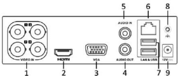
Figure 1-11 Rear Panel of DS-7100
Table 1-10 Descripon of Rear Panel
| No. | Item | Description |
| 1 | VIDEO IN | BNC interface for HDTV1, and analog video input. |
| 2 | HDMI | HDMI video output connector. |
| 3 | VGA | DB15 connector for VGA output. Display local video output and menu. |
| 4 | AUDIO OUT | RCA connector. |
| 5 | AUDIO IN | RCA connector. |
| 6 | Network Interface | Connector for network |
| 7 | USB Port | Universal Serial Bus (USB) port for additional devices. |
| 8 | GND | Ground |
| 9 | Power Supply | 12 VDC power supply. |
Rear Panel 2:
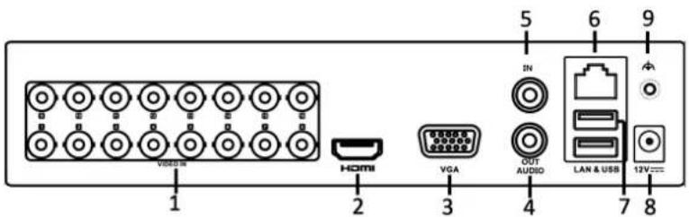
Figure 1-12 Rear Panel of DS-7200HGHI-F (/N)
Rear Panel 3:

Figure 1-13 Rear Panel of DS-7200HGHI-E
Table 1-11 Descripon of Rear Panel
| No. | Item | Description |
| 1 | VIDEO IN | BNC interface for HDTV1 and analog video input. |
| 2 | HDMI | HDMI video output connector. |
| 3 | VGA | DB15 connector for VGA output. Display local video output and menu. |
| 4 | AUDIO OUT | RCA connector |
| 5 | AUDIO IN | RCA connector |
| 6 | Network Interface | Connector for network |
| 7 | USB Port | Universal Serial Bus (USB) port for additional devices. |
| 8 | Power Supply | 12 VDC power supply. |
| 9 | GND | Ground |
Rear Panel 4:

Figure 1-14 Rear Panel of DS-7200HQHI-F1/N
Rear Panel 5:

Figure 1-15 Rear Panel of DS-7200HQHI-F2/N
Table 1-12 Descripon of Rear Panel
| No. | Item | Description |
| 1 | VIDEO IN | BNC interface for HDTVI and analog video input. |
| 2 | AUDIO IN | RCA connector |
| 3 | AUDIO OUT | RCA connector |
| 4 | VGA | DB15 connector for VGA output. Display local video output and menu. |
| 5 | HDMI | HDMI video output connector. |
| 6 | USB Port | Universal Serial Bus (USB) port for additional devices. |
| 7 | Network Interface | Connector for network |
| 8 | RS-485 Interface | Connector for RS-485 devices. |
| 9 | Power Supply | 12VDC power supply. |
| 10 | Power Switch | Switch for turning on/o the device. |
| 11 | GND | Ground |
| 12 | VIDEO OUT | BNC connector for video output. |
| 13 | ALARM | Connector for alarm input/output. |
Rear Panel 6:
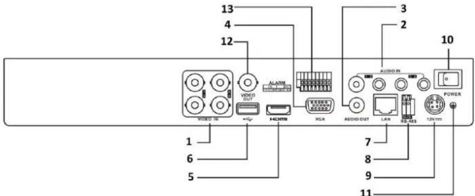
Figure 1-16 Rear Panel of DS-7200HUHI-F/N and 7600HUHI-F/N
i NOTE
The rear panels of DS-7208HUHI-F1/N and DS-7208HUHI-F2/N provide 8 video input interfaces. The rear panel of DS-7216HUHI-F2/N provides 16 video input interfaces.
Table 1-13 Descripon of Rear Panel
| No. | Item | Description |
| 1 | VIDEO IN | BNC interface for HDTVI and analog video input. |
| 2 | AUDIO IN | RCA connector |
| 3 | AUDIO OUT | RCA connector. |
| 4 | VGA | DB15 connector for VGA output. Display local video output and menu. |
| 5 | HDMI | HDMI video output connector. |
| 6 | USB Port | Universal Serial Bus (USB) port for additional devices. |
| 7 | Network Interface | Connector for network |
| 8 | RS-485 Interface | Connector for RS-485 devices. |
| 9 | Power Supply | 12VDC power supply. |
| 10 | Power Switch | Switch for turning on/o the device. |
| 11 | GND | Ground |
| 12 | VIDEO OUT | BNC connector for video output. |
| 13 | Alarm In/Out | Connector for alarm input and output. |
Rear Panel 7:

Figure 1-17 Rear Panel of DS-7300HQHI-F4/N

The rear panel of DS-7304HQHI-F4/N and DS-7308HQHI-F4/N provide 4 and 8 video input interfaces respectively.
Rear Panel 8:

Figure 1-18 Rear Panel of DS-8100HQHI-F8/N

The rear panel of DS-8104HQHI-F8/N and DS-8108HQHI-F8/N provide 4 and 8 video input interfaces respectively.
Table 1-14 Descripon of Rear Panel
| No. | Item | Description |
| 1 | VIDEO IN | BNC interface for HDTV1 and analog video input. |
| 2 | VIDEO OUT | BNC connector for video output. CVBS output is not provided by DS-7100/7200HGHI-E1, DS-7200HGHI-E2, DS-7100/7200HGHI-F1, DS-7200HGHI-F2, DS-7100HQHI-F1/N and DS-7100HGHI-F1/N series DVR. CVBS output is not provided by DS-7100/7200HGHI-E1, DS-7200HGHI-E2, DS-7100/7200HGHI-F1, DS-7200HGHI-F2, DS-7100HQHI-F1/N and DS-7100HGHI-F1/N series DVR. |
| 3 | AUDIO IN | RCA connector |
| 4 | USB Port | Universal Serial Bus (USB) port for additional devices. |
| 5 | HDMI | HDMI video output connector. |
| 6 | VGA | DB15 connector for VGA output. Display local video output and menu. |
| 7 | AUDIO OUT | RCA connector. |
| 8 | Network Interface | Connector for network |
| 9 | RS-485 and Alarm Interface | Connector for RS-485 devices. T+ and T- pins connect to R+ and R- pins of PTZ receiver respectively. |
| D+, D- pin connects to Ta, Tb pin of controller. For cascading devices, the rst DVR's D+, D- pin should be connected with the D+, D- pin of the next DVR. | ||
| Connector for alarm input. | ||
| Connector for alarm output. | ||
| 10 | Power Supply | 100 to 240V AC power supply. |
| 11 | Power Switch | Switch for turning on/o the device. |
| 12 | GND | Ground |
| 13 | LINE IN | BNC connector for audio input. |
| 14 | eSATA | Connects external SATA HDD, CD/DVD-RW. |
| 15 | RS-232 Interface | Connector for RS-232 devices. |
Rear Panel 9:
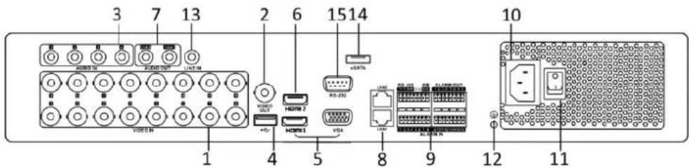
Figure 1-19 Rear Panel of DS-7300HUHI-F4/N
i NOTE
The rear panel of DS-7304HUHI-F4/N and DS-7308HUHI-F4/N provide 4 and 8 video input interfaces respectively.
Rear Panel 10:

Figure 1-20 Rear Panel of DS-8100HUHI-F8/N
i NOTE
The rear panel of DS-8104HUHI-F8/N and DS-8108HUHI-F8/N provide 4 and 8 video input interfaces respectively.
Rear Panel 11:
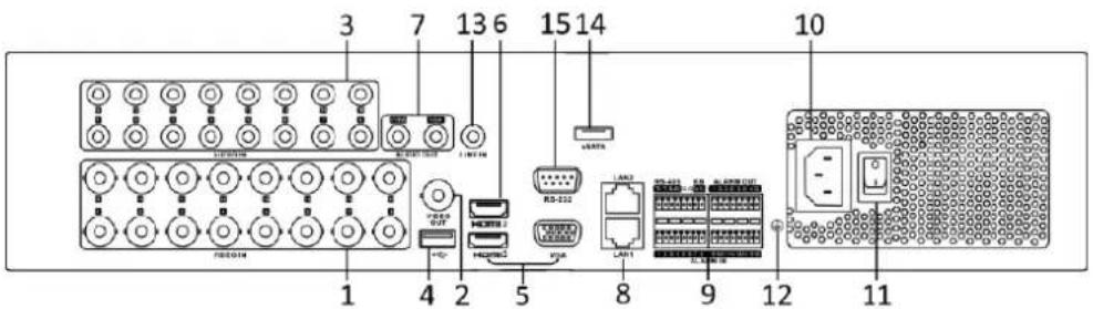
Figure 1-21 Rear Panel of DS-9000HUHI-F8/N

The rear panel of DS-9004HUHI-F8/N and DS-9008HUHI-F8/N provide 4 and 8 video input interfaces respectively.
Table 1-15 Descripon of Rear Panel
| No. | Item | Description |
| 1 | VIDEO IN | BNC interface for HDTV1 and analog video input. |
| 2 | VIDEO OUT | BNC connector for video output. NOTECVBS output is not provided by DS-7100/7200HGHI-E1, DS-7200HGHI-E2, DS-7100/7200HGHI-F1, DS-7200HGHI-F2, DS-7100HQHI-F1/N and DS-7100HGHI-F1/N series DVR. NOTECVBS output is not provided by DS-7100/7200HGHI-E1, DS-7200HGHI-E2, DS-7100/7200HGHI-F1, DS-7200HGHI-F2, DS-7100HQHI-F1/N and DS-7100HGHI-F1/N series DVR. |
| 3 | AUDIO IN | RCA connector |
| 4 | USB Port | Universal Serial Bus (USB) port for additional devices. |
| 5 | HDMI1/VGA | Simultaneous HDMI1/VGA output. Display local video output and menu. |
| 6 | HDMI2 | HDMI2 video output connector. |
| 7 | AUDIO OUT | RCA connector. |
| 8 | Network Interface | Connector for network |
| 9 | RS-485 and Alarm Interface | Connector for RS-485 devices. T+ and T- pins connect to R+ and R- pins of PTZ receiver respectively. |
| D+, D- pin connects to Ta, Tb pin of controller. For cascading devices, the rst DVR's D+, D- pin should be connected with the D+, D- pin of the next DVR. | ||
| Connector for alarm input. | ||
| Connector for alarm output. | ||
| 10 | Power Supply | 100 to 240V AC power supply. |
| 11 | Power Switch | Switch for turning on/o the device. |
| 12 | GND | Ground |
| 13 | LINE IN | BNC connector for audio input. |
| 14 | eSATA | Connects external SATA HDD, CD/DVD-RW. |
| 15 | RS-232 Interface | Connector for RS-232 devices. |
Rear Panel 12:

Figure 1-22 Rear Panel of DS-9000HUHI-F16/N

The rear panel of DS-9008HUHI-F16/N provides 8 video input interfaces.
Table 1-16 Descripon of Rear Panel
| No. | Item | Description |
| 1 | VIDEO IN | BNC interface for TVI and analog video input. |
| 2 | VIDEO OUT | BNC connector for video output.NOTECVBS output is not provided byDS-7100/7200HGHI-E1, DS-7200HGHI-E2,DS-7100/7200HGHI-F1, DS-7200HGHI-F2,DS-7100HQHI-F1/N, and DS-7100HGHI-F1/N series DVR. |
| 3 | AUDIO IN | BNC connector |
| 4 | USB Port | Universal Serial Bus (USB) port for additional devices. |
| 5 | HDMI1/VGA | Simultaneous HDMI1/VGA output. Display local video output and menu. |
| 6 | HDMI2 | HDMI2 video output connector. |
| 7 | AUDIO OUT | BNC connector. |
| 8 | Network Interface | Connector for network |
| 9 | RS-485 and Alarm Interface | Connector for RS-485 devices. T+ and T- pins connect to R+ and R- pins of PTZ receiver respectively. |
| D+, D- pin connects to Ta, Tb pin of controller. For cascading devices, the rst DVR's D+, D- pin should be connected with the D+, D- pin of the next DVR. | ||
| Connector for alarm input. | ||
| Connector for alarm output. | ||
| 10 | Power Supply | 100 to 240 VAC power supply. |
| 11 | Power Switch | Switch for turning on/o the device. |
| 12 | GND | Ground |
| 13 | LINE IN | BNC connector for audio input. |
| 14 | eSATA 1 | Connects external SATA HDD, CD/DVD-RW. |
| 15 | eSATA 2 | Connects external SATA HDD, CD/DVD-RW. |
| 16 | RS-232 Interface | Connector for RS-232 devices. |
| 17 | ALARM OUT | Connector for alarm output. |
Chapter 2 Getting Started
2.1 Starting Up and Shutting Down the DVR
Purpose
Proper startup and shutdown procedures are crucial to expanding the life of the DVR.
Before you start
Check that the voltage of the extra power supply is the same with the DVR's requirement, and the ground conncon is working properly.
Starng up the DVR
Step 1 Check the power supply is plugged into an electrical outlet. It is HIGHLY recommended that an Uninterruptable Power Supply (UPS) be used in conjunction with the device.
Step 2 Turn on the power switch on the rear panel, and the Power indicator LED should turn on indicang that the unit begins to start up.
Step 3 Aer startup, the Power indicator LED remains on.
Shung down the DVR
There are two proper ways to shut down the DVR. To shut down the DVR:
• OPTION 1: Standard shutdown
Step 1 Enter the Shutdown menu.
Menu > Shutdown

Figure 2-1 Shutdown Menu
Step 2 Select the Shutdown buon.
Step 3 Click the Yes buon.
Step 4 Turn o the power switch on the rear panel when the note appears.
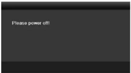
Figure 2-2 Shutdown Tips
Reboong the DVR
While in the Shutdown menu (Figure 2-1), you can also reboot the DVR.
Step 1 Enter the Shutdown menu by clicking Menu > Shutdown.
Step 2 Click the Logout buon to log out or the Reboot buon to reboot the DVR.
2.2 Activating the Device
Purpose
For the rst-me access, you need to acvate the device by seng an admin password. No operaon is allowed before acvaon. You can also acvate the device via Web Browser, SADP or Client Soware.
Step 1 Input the same password in the text eld of Create New Password and Conrm New Password.
![Activation User Name admin Create New P... ********* Strong Confirm New P... ********** ✓ Valid password range [8-16]. You can use a combination of numbers, lowercase, uppercase and special character for your password with at least two kinds of them contained. OK Cancel](/content/2026/05/1005813/images/627130ab34106747989465fea79aaeca2f941a81307c7c161f743a1eb92b0afb.jpg)
Figure 2-3 Sengs Admin Password

WARNING
STRONG PASSWORD RECOMMENDED-We highly recommend you create a strong password of your own choosing (Using a minimum of 8 characters, including at least three of the following categories: upper case leers, lower case leers, numbers, and special characters.) in order to increase the security of your product. And we recommend you reset your password regularly, especially in the high security system, reseng the password monthly or weekly can beer protect your product.
Step 2 Click OK to save the password and acvate the device.
i NOTE
- Clear-text password is supported. Click the icon and you can see the clear text of the password. Click the icon again and the content of the password restores invisible.
- For the old version device, if you update it to the new version, the following dialog box will pop up once the device starts up. You can click YES and follow the wizard to set a strong password.

Figure 2-4 Warning
Step 3 Aer the device is acvated, the Aenon box pops up as below.

Figure 2-5 Aenon
Step 4 (Oponal) Click Yes to export GUID. The Reset Password interface pops up. Click Export to export GUID to the USB ash disk for password reseng.

Figure 2-6 Export GUID
Step 5 Aer exporng GUID, the Aenon box pops up as below. Click Yes to duplicate the password or No to cancel it.

Figure 2-7 Duplicate the Password
2.3 Using the Unlock Pattern for Login

This chapter is only applicable for all the -F series DVR.
Purpose
For the admin, you can congregate the unlock paern for device login.
2.3.1 Configuring the Unlock Pattern
Aer the device is acvated, you can enter the following interface to conjure the device unlock paern.

Figure 2-8 Set Unlock Paern
Step 1 Use the mouse to draw a paern among the 9 dots on the screen. Release the mouse when the paern is done.

Figure 2-9 Draw the Paern

NOTE
- Connect at least 4 dots to draw the paern.
● Each dot can be connected for once only.
Step 2 Draw the same paern again to conrm it. When the two paerns match, the paern is congured successfully.

Figure 2-10 Conrm the Paern

NOTE
If the two paerns are dierent, you must set the paern again.

Figure 2-11 Reset the Paern
2.3.2 Logging in via Unlock Pattern
i NOTE
- Only the admin user has the permission to unlock the device.
- Please congure the paern rst before unlocking. Please refer to Chapter 2.3.1 Conguring the Unlock Paern.
Step 1 Right click the mouse on the screen and select the menu to enter the interface.
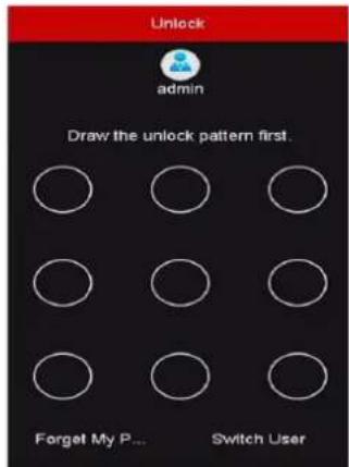
Figure 2-12 Draw the Unlock Paern
Step 2 Draw the pre-dened paern to unlock to enter the menu operaon.
i NOTE
- You can right click the mouse to log in via the normal mode.
- If you have forgotten your paern, you can select the Forget My Paern or Switch User opon to enter the normal login dialog box.
- When the paern you draw is dierent from the paern you have congured, you should try again.
- If you have drawn the wrong paern for 7 mes, the account will be locked for 1 minute.

Figure 2-13 Normal Login Dialog Box

Figure 2-14 Lock the Account
2.4 Basic Configuration in Startup Wizard
2.4.1 Configuring the Signal Input Wizard

For -E series DVR, there is no signal input conguraon interface.
Purpose
For all the -F series DVR, aer the startup and login, the device system enters the Wizard for conguring the signal input.
You can also click Menu > Camera > Signal Input Status to congregate the signal input.
Step 1 Check the checkbox to select dierent signal input types: HD/CVBS and IP.
Step 2 Click Apply to save the sengs.

Figure 2-15 Congure Signal Input Type

For detailed informaon of signal input, you can refer to Chapter 2.7 Conguring the Signal Input Channel for reference.
2.4.2 Using the Wizard for Basic Configuration
Purpose
By default, the Setup Wizard starts once the device has loaded. You can follow it to complete the basic conguraon.
Selecng the language:
Step 1 Select the language from the dropdown list.
Step 2 Click Apply buon.

Figure 2-16 Language Conguraon
Operang the Setup Wizard:
Step 1 The Start Wizard can walk you through some important sengs of the device. If you don't want to use the Start Wizard at that moment, click Exit. You can also choose to use the Start Wizard next me by leaving the "Start wizard when device starts?" checkbox checked.
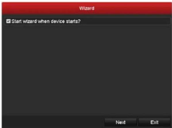
Figure 2-17 Start Wizard Interface
Step 2 Click Next buon to enter the Change the Password interface. Input the Admin Password or change the password.
![Wizard Admin Password ****** New Admin Password New Password ****** Confirm ****** Valid password range [8-16]. You can use a combination of numbers, lowercase, uppercase and special character for your passwords with at least two kinds of them contained Previous Next Exit](/content/2026/05/1005813/images/3afb5412f2d7b6101922bb38262eace2c08948b969f3f5e27df6206f31d8e02f.jpg)
Figure 2-18 Change the Password

Clear-text password is supported. Click the icon and you can see the clear text of the password. Click the icon again and the content of the password restores invisible.
Step 3 Click Next buon and the Aenon box pops up as shown below. Click Yes to duplicate the password of the device to IP cameras that are connected with default protocol. Or click No to enter the Date and Time Sengs interface.
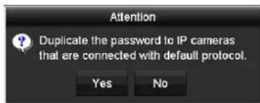
Figure 2-19 Duplicate the Password

Figure 2-20 Date and Time Sengs
Step 4 After the me sengs, click Next buon to enter the General Network Setup Wizard interface as shown below.

Figure 2-21 General Network Conguraon
i NOTE
- 2 self-adapve 10M/100M/1000M network interfaces for DS-8100HQHI-F/N and DS-7300/8100/9000HUHI-F/N series. For DS-8100HQHI-F/N series, three working modes are congorable: mul-address, load balance, network fault tolerance. For DS-7300/8100/9000HUHI-F/N series, only mul-address and network fault tolerance are congorable. 1 self-adapve 10M/100M/1000M network interface or 1 self-adapve 10M/100Mbps network interface provided for other models.
- For all the -F series DVR, if DHCP is enabled, you can check the checkbox of Enable DNS DHCP or uncheck it and edit the Preferred DNS Server and Alternate DNS Server.
Step 5 Click Next buon after you congured the basic network parameters. Then you will enter the Hik Cloud P2P interface. Congure the Hik Cloud P2P according to your need.

Figure 2-22 Hik Cloud P2P Interface
Step 6 Click Next buon to enter the Advanced Network Parameters interface. You can enable DDNS and set other ports according to your need.

Figure 2-23 Set Advanced Network Parameters
Step 7 For DS-7300/8100/9000HUHI-F/N series, click Next buon and you can enter the RAID conguraon interface. Check the checkbox of Enable RAID to take this funcon into eect.

Figure 2-24 RAID Conguraon
Step 8 Click Next buon aer conguring the advanced network parameters, which will take you to the HDD Management interface as shown in Figure 2-22.

Figure 2-25 HDD Management
Step 9 To initialize the HDD, click the Init buon. Inializaon will remove all the data saved in the HDD.
Step 10 Click Next buon to enter the IP Camera Management interface.
Step 11 Add the IP camera.
1) Click Search to search the online IP Camera. The Security status shows whether it is acve or inacve. Before adding the camera, make sure the IP camera to be added is in acve status. If the camera is in inacve status, you can click the inacve icon of the camera to set the password to acvate it. You can also select mulple cameras from the list and click the One-touch Acvate to acvate the cameras in batch.
2) Click the Add to add the camera.
3) (Oponal) Check the checkbox of Enable H.265 (For Inial Access) for the connected IP camera supporting H.265. Then the IP camera will be encoded with H.265.

The Enable H.265 opon is only applicable to DS-7300/8100/9000HUHI-F/N series.

Figure 2-26 IP Camera Management
Step 12 Aer nishing IP Camera sengs, click Next to enter the Record Sengs interface.
Step 13 Click the icon, and you can enable the connuous recording or moon detecon recording for all channels of the device.

Figure 2-27 Record Sengs
Step 14 Click OK to complete the wizard sengs.
2.5 Login and Logout
2.5.1 User Login
Purpose
You have to log in to the device before operang the menu and other funcons
Step 1 Select the User Name in the dropdown list.

Figure 2-28 Login Interface
Step 2 Input the Password.
Step 3 Click OK to log in.
i NOTE
- Clear-text password is supported. Click the 📄 on and you can see the clear text of the password. Click the icon again and the content of the password restores invisible.
- In the Login interface, for the admin, if you have entered the wrong password for 7 mes, the account will be locked for 60 seconds. For the operator, if you have entered the wrong password for 5 mes, the account will be locked for 60 seconds.

Figure 2-29 User Account Protecon for the Admin

Figure 2-30 User Account Protecon for the Operator
Step 4 (Optional) If you forget the password, click Forget Password to pop up the Import GUID interface.
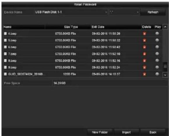
Figure 2-31 Import GUID
1) Select the GUID le from the USB ash disk and click Import buon to pop up the Reset Password interface.
![Reset Password User Name admin Create New Pass... Confirm New Pass... ✓ Valid password range [8-16]. You can use a combination of numbers, lowercase, uppercase and special character for your password with at least two kinds of them contained. OK Cancel](/content/2026/05/1005813/images/20321fe606728078f332a2d3feef1408972816012795ead6a954d63849fc1b3a.jpg)
Figure 2-32 Reset Password
2) Input the new password and conrm the password.
3) Click OK to save the new password. Then the Attenon box pops up as shown below.

Figure 2-33 GUID File Imported
4) Click OK and the Aenon box as below pops up to remind you to duplicate the password of the device to IP cameras that are connected with default protocol. Click Yes to duplicate the password or No to cancel it.

Figure 2-34 Duplicate the Password
i NOTE
- If you want to retrieve the password when you forget it, you must export the GUID le rst.
- Once the password is reset, the GUID le becomes ineece. You can export a new GUID le. Refer to Chapter 17.5.3 Eding a User for reference.
2.5.2 User Logout
Purpose
Aer logging out, the monitor turns to the live view mode and if you want to perform some operaons, you need to enter the user name and password to log in again.
Step 1 Enter the Shutdown menu.
Menu > Shutdown

Figure 2-35 Logout
Step 2 Click Logout.

Aer you have logged out of the system, menu operaon on the screen is invalid. It is required to input a user name and password to unlock the system.
2.6 Adding and Connecting the IP Cameras
2.6.1 Activating the IP Camera

The IP camera conncon is not supported by DS-7100 series DVR.
Purpose
Before adding the camera, make sure the IP camera to be added is in acve status.
Step 1 Select the Add IP Camera opon from the right-click menu in live view mode or click Menu> Camera> IP Camera to enter the IP Camera Management interface.
For the IP camera detected online in the same network segment, the Security status shows whether it is acve or inacve.

Figure 2-36 IP Camera Management Interface
Step 2 Click the inacve icon of the camera to enter the following interface to acvate it. You can also select mulple cameras from the list and click the One-touch Acvate to acvate the cameras in batch.
![Activation Use Admin Password Create New P... Confirm New P... ✓ Valid password range [8-16]. You can use a combination of numbers, lowercase, uppercase and special character for your password with at least two kinds of them contained. OK Cancel](/content/2026/05/1005813/images/15be801320eade5288afc50293fa088a455d4d3f30ffd1c8da905dfa994bbfd2.jpg)
![One-touch Activate Use Admin Password Create New P... Confirm New P... ✓ Valid password range [6-16]. You can use a combination of numbers, lowercase, uppercase and special character for your password with at least two kinds of them contained. OK Cancel](/content/2026/05/1005813/images/e872cb8ef9d99515ef253299ceb45996386bbcaec6f196c1bd89c5810ab902d0.jpg)
Figure 2-37 Acvate the Camera
Step 3 Set the password of the camera to acvate it.
Use Admin Password: When you check the checkbox, the camera (s) will be congured with the same admin password of the operang DVR.
Create New Password: If the admin password is not used, you must create the new password for the camera and conrm it.
![Activation ■ Use Admin Password Create New P... ***** Confirm New P... ***** ✓ Valid password range [8-16]. You can use a combination of numbers, lowercase, uppercase and special character for your password with at least two kinds of them contained. OK Cancel](/content/2026/05/1005813/images/50aee328a0e6609381ce03312059cc6a8853f37899b46b8605ef809b6f1b1b60.jpg)
Figure 2-38 Set New Password

WARNING
STRONG PASSWORD RECOMMENDED-We highly recommend you create a strong password of your own choosing (Using a minimum of 8 characters, including at least three of the following categories: upper case letters, lower case leers, numbers, and special characters.) in order to increase the security of your product. And we recommend you reset your password regularly, especially in the high security system, reseng the password monthly or weekly can beer protect your product.
Step 4 Click OK to nish the acitavng of the IP camera. And the security status of camera will be changed to Acve.
2.6.2 Adding the Online IP Camera
Purpose
Before you can get a live view or record of the video, you should add the network cameras to the conncon list of the device.
Before you start
Ensure the network conncon is valid and correct. For detailed checking and conguring of the network, please see Chapter 12 Network Sengs.
- OPTION 1:
Step 1 Select the Add IP Camera opon from the right-click menu in live view mode or click Menu> Camera> IP Camera to enter the IP Camera Management interface.

Figure 2-39 IP Camera Management Interface
Step 2 The online cameras with same network segment will be detected and displayed in the camera list.
Step 3 Select the IP camera from the list and click the buon to add the camera (with the same admin password of the DVR's). Or you can click the One-touch Adding buon to add all cameras (with the same admin password) from the list.

Make sure the camera to add has already been acavted by seng the admin password, and the admin password of the camera is the same with the DVR's.
Step 4 (Oponal) For DS-7300/8100/9000HUHI-F/N series DVR, check the checkbox of Enable H.265 (For Inial Access) for the connected IP camera supporting H.265. Then the IP camera will be encoded with H.265.
Step 5 (For the encoders with mulple channels only) check the checkbox of Channel Port in the pop-up window, as shown in the following gure, and click OK to add mulple channels.

Figure 2-40 Select Mulple Channels
- OPTION 2:
Step 1 On the IP Camera Management interface, click the Custom Adding button to pop up the Add IP Camera (Custom) interface.

Figure 2-41 Custom Adding IP Camera Interface
Step 2 You can edit the IP address, protocol, management port, and other informaon of the IP camera to be added.

If the IP camera to add has not been acavated, you can acvate it from the IP camera list on the IP Camera Management interface.
Step 3 Click Add to add the camera.
For the successfully added IP cameras, the Security status shows the security level of the password of camera: strong password, weak password and risky password.

Figure 2-42 Successfully Added IP Cameras
Please refer to Chapter 18.1 Specicaons for the number of connectable IP cameras for dierent models.
Table 2-1 Explanaon of the icons
| Icon | Explanation | Icon | Explanation |
 | Edit basic parameters of the camera |  | Add the detected IP camera. |
| [80AX] | The camera is disconnected; You can click the icon to get the excepon informaon of camera. | [2KY5] | Delete the IP camera |
 | Play the live video of the connected camera. |  | Advanced sengs of the camera. |
 | Upgrade the connected IP camera. | Security | Shows the security status of the camera to be acve/inacve or the password strength (strong/medium/weak/risky) |
Step 4 (Oponal) For DS-7300/8100/9000HUHI-F/N series DVR, check the checkbox of Enable H.265 (For Inial Access) for the connected IP camera supporting H.265. Then the IP camera will be encoded with H.265.
2.6.3 Editing the Connected IP Camera
Purpose
Aer the adding of the IP cameras, the basic informaon of the camera is listed on the interface, and you can congure the basic sengs of the IP cameras.
Step 1 Click the 📋 icon to edit the parameters. You can edit the IP address, protocol and other parameters.
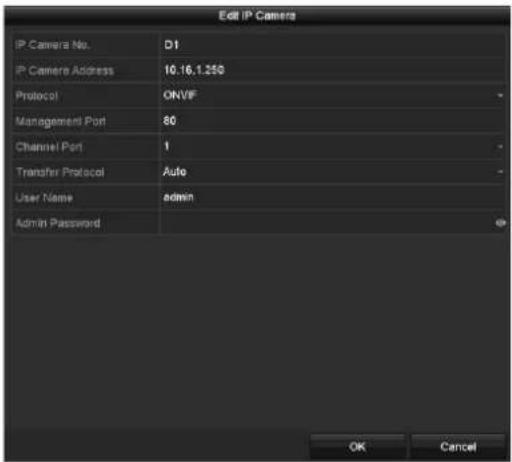
Figure 2-43 Edit IP Camera
Channel Port: If the connected device is an encoding device with mulple channels, you can choose the channel to connect by selecng the channel port No. in the dropdown list.
Step 2 Click OK to save the sengs and exit from the eding interface.
Step 3 Drag the horizontal scroll bar to the right side and click the icon to edit the advanced parameters.

Figure 2-44 Network Conguraon of the Camera
Step 4 You can edit the network informaon and the password of the camera.
![Advanced Settings Network Password IP Camera No D1 Current Password 0 New Password 0 Confirm 0 • Valid password range [8-16]. You can use a combination of numbers, lowercase, uppercase and special character for your password with at least two kinds of them contained. Apply OK Cancel](/content/2026/05/1005813/images/6462a441cfe34d28caa562d346ca603e0de36d1b9eb33b86e43c7a4c558c70ac.jpg)
Figure 2-45 Password Conguraon of the Camera
Step 5 Click OK to save the sengs and exit the interface.
2.7 Configuring the Signal Input Channel

For -E series DVR, there is no signal input conguraon interface.
Purpose
For all the -F series DVR, you should congregate the analog and IP signal input types.
Step 1 Enter the Signal Input Status interface.
Menu > Camera > Signal Input Status
Step 2 Check the checkbox to select dierent signal input types: HD/CVBS and IP. If you select HD/CVBS, four kinds of analog signal inputs including HDTV1, AHD, HDCVI and CVBS can be connected randomly for the selected channel. If you select IP, IP camera can be connected for the selected channel.

Figure 2-46 Congure Signal Input Type
Step 3 Click Apply to save the sengs.
i NOTE
● The AHD signal input is only supported by the -F series DVR.
- For -E series DVR, there is no signal input conguraon interface. Each two video channels are grouped in sequence, e.g., CH01 and CH02, CH03 and CH04...; and each two channels in the same group must be connected with the same type of video source (HDTVI or CVBS).
- For all the –F series DVR, four kinds of analog signal inputs including HDTVI (including 3 MP, 1080p and 720p signal), AHD, HDCVI and CVBS can be connected. The analog signal inputs can be recognized automatically and can be mixed randomly.
- For HQHI series DVR, the 3 MP signal can be accessed for the rst channel of DVR with 4-ch video inputs, the rst 2 channels of DVR with 8-ch video inputs and the rst 4 channels of DVR with 16-ch video inputs.
- For all the -F series DVR, when HDTV1, AHD, or HDCVI input is connected, the informaon including the resoluon and frame rate (e.g., 720P25) will be overlaid on the boom right corner of the live view for 5 seconds. When CVBS input is connected, the informaon such as NTSC or PAL will be overlaid on the boom right corner of the live view for 5 seconds. When there is no video signal for the channel, the connectable video signal type message will not be displayed on the screen. When the unsupported signal input is connected, no video message is displayed on the screen. You can refer to the speciaons for the supported resoluon of the analog signal input types.
- For –F series DVR, you can view the max. IP camera accessible number in the Max. IP Camera Number text eld. For DS-7300/8100/9000HUHI-F/N and DS-7300/8100HQHI-F/N series DVR, disabling one analog channel will add one IP channel. For DS-7300/8100HUHI-F/N and DS-7300/8100HQHI-F/N series, the accessible IP channels are X+2 (X refers to the disabled analog channel or channels of the DVR.). For DS-9004HUHI-F8/N series, the accessible IP channels are X+6 (X refers to the disabled analog channel or channels of the DVR.). For DS-9008HUHI-F/N series, the accessible IP channels are X+10 (X refers to the disabled analog channel or channels of the DVR.). For DS-9016HUHI-F/N series, the accessible IP channels are X+18 (X refers to the disabled analog channel or channels of the DVR.) and the max. IP channels are 32.
Chapter 3 Live View
3.1 Introduction of Live View
Live view shows you the video image geng from each camera in real me. The DVR will automacally enter Live View mode when powered on. It is also at the very top of the menu hierarchy, thus hing the ESC many mes (depending on which menu you're on) will bring you to the Live View mode.
Live View Icons
In the live view mode, there are icons at the right top of the screen for each channel, showing the status of the record and alarm in the channel, so that you can know whether the channel is recorded, or whether there are alarms occur as soon as possible.
Table 3-1 Descripon of Live View Icons
| Icons | Description |
| Alarm (video loss, tampering, moon detecon, VCA or sensor alarm) | |
| Record (manual record, schedule record, moon detecon or alarm triggered record) | |
| Alarm & Record | |
| Event/Excepon (moon detecon, sensor alarm or excepon informaon. For details, see Chapter 8.6 Handling Excepons.) |
3.2 Operations in Live View Mode
In live view mode, there are many funcons provided. The funcons are listed below.
● Single Screen: show only one screen on the monitor.
- Mul-screen: show mulple screens on the monitor simultaneously.
- Start Auto-switch: the screen is auto switched to the next one. And you must set the dwell me for each screen on the conguraon menu before enabling the auto-switch. Menu>Conguraon>Live View>Dwell Time.
- Start Recording: normal record and moon detecon record are supported.
- Output Mode: select the output mode to Standard, Bright, Gentle or Vivid.
- Playback: play back the recorded videos for current day.
- Aux/Main Monitor: the DVR checks the conneccon of the output interfaces to dene the main and auxiliary output interfaces. When the aux output is enabled, the main output cannot do any operaon, and you can do some basic operaon on the live view mode for the Aux output.
For DS-7300/8100/9000HUHI-F/N series, there are two HDMI interfaces. HDMI1 and VGA interfaces share simultaneous output. The priority level for the main and aux output is HDMI2> VGA/HDMI1. The CVBS output only serves as the aux output or live view output. The priority relationship is shown as Table 3-2.
Table 3-2 Priories of Outputs for DS-7300/8100/9000HUHI-F/N Series
| S.N | HDMI2 | VGA/HDMI1 | CVBS | Main output | Auxiliary output | For Live View Output Only |
| 1 | √ | √ | √ or × | HDMI2 | VGA/HDMI1 | CVBS |
| 2 | √ or × | × | √ or × | HDMI2 | CVBS | VGA/HDMI1 |
| 3 | × | √ | √ or × | VGA/HDMI1 | CVBS | HDMI2 |
For DS-7608/7616HUHI-F/N and DS-7300/8100HQHI-F/N series DVR, the HDMI and VGA interfaces can be congured to be simultaneous or independent.
For DS-7608/7616HUHI-F/N and DS-7300/8100HQHI-F/N series DVR with CVBS output, if the HDMI and VGA interfaces are congured to be independent, the priority level of the main and aux output is HDMI > VGA. The CVBS output only serves as the aux output or live view output. The priority relationship is shown as Table 3-3. If the HDMI and VGA interfaces are congured to be simultaneous, the VGA/HDMI output is the main output. The CVBS output is the aux output. The priority relationship is shown as Table 3-4.
Table 3-3 Priories of Independent Outputs for DS-7608/7616HUHI-F/N and DS-7300/8100HQHI-F/N Series
| S.N | HDMI | VGA | CVBS | Main output | Auxiliary output | For Live View Output Only |
| 1 | √ | √ | √ or × | HDMI | VGA | CVBS |
| 2 | √ or × | × | √ or × | HDMI | CVBS | VGA |
| 3 | × | √ | √ or × | VGA | CVBS | HDMI |
Table 3-4 Priories of Simultaneous Outputs for DS-7608/7616HUHI-F/N and DS-7300/8100HQHI-F/N Series
| S.N | HDMI | VGA | CVBS | Main output | Auxiliary output |
| 1 | or × | or × | or × | VGA/HDMI | CVBS |
For DS-7200HQHI-F/N and DS-7200/7604HUHI-F/N series DVR with CVBS output, the VGA/HDMI output is the main output, and the CVBS output is the aux output. The priority relationship is shown as Table 3-5.
For HGHI-F/N, HGHI-F, DS-7100HQHI-F/N series DVR, there is no CVBS output. The VGA/HDMI output is the main output. The priority relationship is shown as Table 3-6.
Table 3-5 Priories of Outputs for DS-7200HQHI-F/N and DS-7200/7604HUHI-F/N Series
| S.N | HDMI | VGA | CVBS | Main output | Auxiliary output |
| 1 | or × | or × | or × | VGA/HDMI | CVBS |
Table 3-6 Priories of Outputs for HGHI-F/N, HGHI-F, DS-7100HQHI-F/N Series
| S.N | HDMI | VGA | Main output |
| 1 | or × | or × | VGA/HDMI |

√ means the interface is in use, × means the interface is out of use or the conncon is invalid. And the HDMI, VGA and CVBS can be used at the same me.
3.2.1 Using the Mouse in Live View
You can refer to Table 3-7 for the descripon of mouse operaon in live view mode.
Table 3-7 Mouse Operaon in Live View
| Name | Description |
| Menu | Enter the main menu of the system by right clicking the mouse. |
| Single Screen | Switch to the single full screen by choosing channel number from the dropdown list. |
| Multi-Screen | Adjust the screen layout by selecng from the dropdown list.  For DS-7300/8100/9000HUHI-F/N series DVR, if the sum of the analog and IP channels exceeds 25, up to 32-window division mode is supported for the VGA/HDMI1 output. For DS-7300/8100/9000HUHI-F/N series DVR, if the sum of the analog and IP channels exceeds 25, up to 32-window division mode is supported for the VGA/HDMI1 output. |
| Previous Screen | Switch to the previous screen. |
| Next Screen | Switch to the next screen. |
| Start/Stop Auto-Switch | Enable/disable the auto-switch of the screens.  The dwell me of the live view conguraon must be set before using Start Auto-Switch. The dwell me of the live view conguraon must be set before using Start Auto-Switch. |
| Start Recording | Start recording of all channels, Connuous Record and Moon Detecon Record are selectable from the dropdown list. |
| Add IP Camera | A shortcut to enter the IP camera management interface.(For HDVR series only) |
| Playback | Enter the playback interface and start playing back the video of the selected channel immediately. |
| PTZ Control | A shortcut to enter the PTZ control interface of the selected camera. |
| Output Mode | Output Mode is congorable with Standard, Bright, Gentle and Vivid opons. |
| Aux Monitor | Switch to the auxiliary output mode and the operaon for the main output is disabled. _ _  If you enter Aux monitor mode and the Aux monitor is not connected, the mouse operaon is disabled. You need to switch back to the Main output with the F1 buon on front panel or VOIP/MON buon on IR remote control and then press the Enter buon. If you enter Aux monitor mode and the Aux monitor is not connected, the mouse operaon is disabled. You need to switch back to the Main output with the F1 buon on front panel or VOIP/MON buon on IR remote control and then press the Enter buon. |

Figure 3-1 Right-click Menu
3.2.2 Switching Main/Aux Output
i NOTE
- Except –HGHI and DS-7100HQHI-F/N series DVR, other series DVR support Aux/Main output switch. Refer to the tables of Chapter 3.2 Operaons in Live View Mode for the main and aux output relationship.
- For the DVR with CVBS output, the CVBS output only serves as the aux output or live view output.
Step 1 Use the mouse wheel to double-click on the HDMI1/VGA, or HDMI2, or HDMI/VGA, or HDMI, or VGA output screen, and the following message box pops up.

Figure 3-2 Switch Main and Aux Output
Step 2 Use the mouse wheel to double-click on the screen again to switch to the aux output, or click Cancel to cancel the operaon.
Step 3 Select the Menu Output Mode to others from the right-click menu on the monitor.
Step 4 On the pop-up message box, click Yes to reboot the device to enable the selected menu output as the main output.
i NOTE
You can select the Menu Output Mode under Menu>Conguraon>General>More Sengs to Auto, HDMI1/VGA and HDMI2 (for DS-7300/8100/9000HUHI-F/N) or Auto, HDMI and VGA (for
independent output conguraon of DS-7608/7616HUHI-F/N and DS-7116/7216/7300/8100HQHI-F/N series), Auto and HDMI/VGA (for HGHI-F/N, HGHI-F, DS-7100/7200HQHI-F/N and DS-7200/7604HUHI-F/N series or simultaneous output conguraon of DS-7608/7616HUHI-F/N and DS-7300/8100HQHI-F/N series) and then reboot the device to switch the main output.
3.2.3 Quick Setting Toolbar in Live View Mode
On the screen of each channel, there is a quick seng toolbar which shows when you click the screen.

Figure 3-3 Quick Seng Toolbar
You can refer to Table 3-5 for the descripon of Quick Seng Toolbar icons.
Table 3-8 Descripon of Quick Seng Toolbar Icons
| Icons | Description | Icons | Description | Icons | Description |
 | Enable/Disable Manual Record |  | Instant Playback |  | Mute/Audio on |
 | PTZ Control |  | Digital Zoom |  | Image Sengs |
 | Close Live View |  | Face Detecon | [7TBY] | Informaon |
 | Capture |

Picture capture is applicable to DS-7300/8100/9000HUHI-F/N series DVR only.

Instant Playback only shows the record in last ve minutes. If no record is found, it means there is no record during the last ve minutes.

Digital Zoom can zoom in the selected area to the full screen. Click and draw to select the to zoom in, as shown in Figure 3-4.

natural_image
Highway scene with vehicles and shipping containers, residential buildings in background (no visible text or symbols)Figure 3-4 Digital Zoom
Image Sengs icon can be selected to enter the Image Sengs menu. You can drag the mouse or click 📄 to adjust the image parameters, including brightness, contrast, and saturaon. Refer to the Chapter 15.3 Conguring Video Parameters for details.

Figure 3-5 Image Sengs
Face Detecon can be enabled if you click the icon. The dialog pops up as shown in Figure 3-6. Click Yes and the full-screen live view of the channel is enabled. You can click ✗ to exit from the full-screen mode.

Figure 3-6 Enable Face Detecon

You can congregate face detection only when it is supported by the connected camera.

Move the mouse onto the Informaon icon to show the real-me stream informaon, using the frame rate, bit rate, resoluon and stream type.

Figure 3-7 Informaon

NOTE
For DS-7300/8100/9000HUHI-F/N series DVR, when H.264 IP camera is connected, the stream type is displayed as H.264. When Smart 264 IP camera is connected, the stram type is displayed as H.264+. When H.265 IP camera is connected, the stream type is displayed as H.265. When Smart 265 IP camera is connected, the stram type is displayed as H.265+.
3.3 Channel-Zero Encoding

NOTE
This secon is not applicable to DS-7100/7200HGHI-E1/E2 series DVR.
Purpose
Sometimes you need to get a remote view of many channels in real me from web browser or CMS (Client Management System) soware, in order to decrease the bandwidth requirement without aecng the image quality, channel-zero encoding is supported as an opon for you.
Step 1 Enter the Live View Sengs interface.
Menu> Conguraon> Live View
Step 2 Select the Channel-Zero Encoding tab.
| Enable Channel-Zero Enc... | ✓ |
| Frame Rate | 12fps |
| Max. Bitrate Mode | General |
| Max. Bitrate(Kbps) | 1024 |
Figure 3-8 Live View- Channel-Zero Encoding
Step 3 Check the checkbox aer Enable Channel-Zero Encoding.
Step 4 Congure the Frame Rate, Max. Bitrate Mode and Max. Bitrate.
Step 5 Click the Apply buon to acvate the sengs.
Step 6 Aer you set the Channel-Zero encoding, you can get a view in the remote client or web browser of 16 channels in one screen.
3.4 Adjusting Live View Settings
Purpose
Live View sengs can be customized according to dierent needs. You can conjure the output interface, dwell me for screen to be shown, mute or turning on the audio, the screen number for each channel, etc.
Step 1 Enter the Live View Sengs interface.
Menu> Conguraon> Live View

Figure 3-9 Live View-General (1)
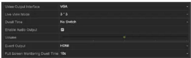
Figure 3-10 Live View-General (2)
The sengs available in this menu include:
- Video Output Interface: Selects the output to conjure the sengs.
For DS-7300/8100/9000HUHI-F/N series DVR, you can select VGA/HDMI1, HDMI2, Main CVBS for video output interface.
For DS-7608/7616HUHI-F/N and DS-7300/8100HQHI-F/N series DVR with CVBS output, if you have congured HDMI/VGA simultaneous output, you can select Main CVBS, HDMI/VGA for the video output interface. If you have congured independent HDMI and VGA output, you can select Main CVBS, HDMI and VGA for the video output interface.
For other models, if CVBS output is supported, you can select Main CVBS and HDMI/VGA for video output interface. If CVBS output is not supported, HDMI/VGA serves as the video output interface.
● Live View Mode: Selects the display mode to be used for Live View.
- Dwell Time: The me in seconds to dwell between switching of channels when enabling auto-switch in Live View.
- Enable Audio Output: Enables/disables audio output for the selected camera in the live view mode.
● Volume: Adjust the volume of the audio output.
- Event Output: Designates the output to show event video. If available, you can select a dierent video output interface from the Video Output Interface when an event occurs.
● Full Screen Monitoring Dwell Time: The me in seconds to show alarm event screen.
Step 2 Set the camera order.
1) Click View tab and select the Video Output Interface from the dropdown list.
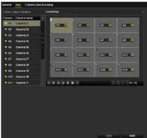
Figure 3-11 Live View-Camera Order
2) Click a window to select it, and then double-click a camera name in the camera list you would like to display. Seng an 'X' means the window will not display any camera.
3) You can also click 📋 to start live view of all channels in order and click 📋 to stop live view of all channels. Click 📋 or 📋 to go to the previous or next page.
4) Click the Apply buon.

For DS-7300/8100/9000HUHI-F/N series DVR, if the sum of the analog and IP channels exceeds 25, up to 32-window division mode is supported for the VGA/HDMI1 output.
3.5 Manual Video Quality Diagnostics
Purpose
The video quality of the analog channels can be diagnosed manually and you can view the diagnosc results from a list.
Step 1 Enter the Manual Video Quality Diagnoscs interface.
Menu> Manual >Manual Video Quality Diagnoscs

Figure 3-12 Video Quality Diagnoscs
Step 2 Check the checkboxes to select the channels for diagnoses.
Step 3 Click the buon Diagnose, and the results will be displayed on a list. You can view the video status and diagnoses me of the selected channels.

Figure 3-13 Diagnoscs Result
i NOTE
- Connect the camera to the device for the video quality diagnoses.
- Three excepon types can be diagnosed: Blurred Image, Abnormal Brightness and Color Cast.
Chapter 4 PTZ Controls
4.1 Configuring PTZ Settings
Purpose
Follow the procedure to set the parameters for PTZ. The conguring of the PTZ parameters should be done before you control the PTZ camera.
Step 1 Enter the PTZ Sengs interface.
Menu >Camera> PTZ
![PTZ Camera [A1] Camera 01 Pressl Set Clear Clear All Call Patrol 1 Set Clear Clear All Call Pattern 1 Start Stop Clear All Linear Scan Left Last Right Limit PTZ Parameter ... Enable Omnicast Control Speed Zoom - Focus - Inc - PTZ Back](/content/2026/05/1005813/images/b0894fdd2c82e36b0211c50c509db342e8feb8746e77674af2a6952ad505e61f.jpg)
Figure 4-1 PTZ Sengs
Step 2 Select the camera for PTZ seng in the Camera dropdown list.
Step 3 Click the PTZ Parameters buon to set the PTZ parameters.
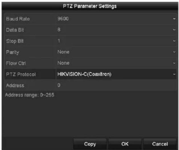
Figure 4-2 PTZ- General
Step 4 Select the parameters of the PTZ camera from the dropdown list.
i NOTE
● All the parameters should be exactly the same as the PTZ camera parameters.
- For the Coaxitron camera/dome connected, you can select the PTZ protocol to HIKVISION-C (Coaxitron). Make sure the protocol selected here is supported by the connected camera/dome.
- When the Coaxitron protocol is selected, all the other parameters like the baud rate, data bit, stop bit, parity and ow control are not congorable.
Step 5 (Oponal) Click Copy buon to copy the sengs to the other channels. Select the channels you want to copy to and click OK to return to the PTZ Parameters Sengs interface.

Figure 4-3 Copy to Other Channels
Step 6 Click OK to save the sengs.
Step 7 (Oponal) Check the checkbox of Enable Omnicast Control to enable the PTZ control of the selected camera via Omnicast VMS of Genetec.
4.2 Setting PTZ Presets, Patrols and Patterns
Before you start
Please make sure that the presets, patrols and paerns should be supported by PTZ protocols.
4.2.1 Customizing Presets
Purpose
Follow the steps to set the Preset locaon which you want the PTZ camera to point to when an event takes place.
Step 1 Enter the PTZ Sengs interface.
Menu>Camera>PTZ
![PTZ Camera [A1] Camera 01 Present Set Clear Clear All Call Pathol 1 Set Clear Clear All Call Pattern 1 Start Stop Clear All Linear Scan Left Limit Right Limit PTZ Parameter ... Enable Omnicest Control Zoom - Focus - Iris - Speed -](/content/2026/05/1005813/images/2ac0912384d9b67d9bfce5bc4790db183d8ec7b0b58309a03f41a88033c553b6.jpg)
Figure 4-4 PTZ Sengs
Step 2 Use the direconal buon to wheel the camera to the locaon where you want to set preset; and the zoom and focus operaons can be recorded in the preset as well.
Step 3 Enter the preset No. (1\~255) in the preset text eld, and click the Set buon to link the locaon to the preset.
Repeat the steps from 2 to 3 to save more presets.
You can click the Clear buon to clear the locaon informaon of the preset, or click the Clear All buon to clear the locaon informaon of all the presets.
4.2.2 Calling Presets
Purpose
This feature enables the camera to point to a specied posion such as a window when an event takes place.
Step 1 Click the buon PTZ in the lower-right corner of the PTZ seng interface;
Or press the PTZ buon on the front panel or click the PTZ Control icon in the quick seng bar, or select the PTZ opon in the right-click menu to show the PTZ control panel.
Step 2 Choose Camera in the dropdown list.
Step 3 Click the General tab to show the general sengs of the PTZ control.
![PTZ Camera [D1] IPdome Configuration PTZ Co... One-tou... General Call Preset Call Patrol Stop Pa... 1 Call Patt... Stop Pa... 1](/content/2026/05/1005813/images/b5349128b2838b2110703bf5e98f7ec0d531f1cd270813975856f56fbaf0d6da.jpg)
Figure 4-5 PTZ Panel-General
Step 4 Click to enter the preset No. in the corresponding text eld.
Step 5 Click the Call Preset buon to call it.

When the Coaxitron camera/dome connected and the PTZ protocol is selected to HIKVISION-C (Coaxitron), you can call the preset 95 to enter the menu of the connected Coaxitron camera/dome. Use the direconal buons on the PTZ control panel to operate the menu.
4.2.3 Customizing Patrols
Purpose
Patrols can be set to move the PTZ to dierent key points and have it stay there for a set duraon before moving on to the next key point. The key points are corresponding to the presets. The presets can be set following the steps above in Customizing Presets.
Step 1 Enter the PTZ Sengs interface.
Menu>Camera>PTZ
![PTZ Camera [A1] Camera 01 Preset Set Clear Clear All Call Patrol 1 Set Clear Clear All Call Patient 1 Start Stop Clear All Linear Scan Left Limit Right Limit PTZ Parameter ... Enable Omnicest Control Zoom - Focus - Iris - Speed PTZ Back](/content/2026/05/1005813/images/f05948ff2d4ecc62d093ea976d223aa3f540c81a213a179a579b2ff58b40c92e.jpg)
Figure 4-6 PTZ Sengs
Step 2 Select patrol No. in the drop-down list of patrol.
Step 3 Click the Set buon to add key points for the patrol.
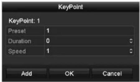
Figure 4-7 Key point Conguraon
Step 4 Congure key point parameters, such as the key point No., duraon of staying for one key point and speed of patrol. The key point is corresponding to the preset. The Key Point No. determines the order at which the PTZ will follow while cycling through the patrol. The Duraon refers to the me span to stay at the corresponding key point. The Speed denes the speed at which the PTZ will move from one key point to the next.
Step 5 Click the Add buon to add the next key point to the patrol, or you can click the OK buon to save the key point to the patrol.
You can delete all the key points by clicking the Clear buon for the selected patrol, or click the Clear All buon to delete all the key pints for all patrols.
4.2.4 Calling Patrols
Purpose
Calling a patrol makes the PTZ to move according the predened patrol path.
Step 1 Click the buon PTZ in the lower-right corner of the PTZ Sengs interface;
Or press the PTZ buon on the front panel or click the PTZ Control icon in the quick seng bar, or select the PTZ opon in the right-click menu to show the PTZ control panel.
Step 2 Click the General tab to show the general sengs of the PTZ control.
![PTZ Camera [D1] IPdome Configuration PTZ Co... One-tou... General Call Preset Call Patrol Stop Pa... 1 Call Patt... Stop Pa... 1](/content/2026/05/1005813/images/44ddd35109c487f428c7232fa6e9ec1fc75ab0a44c9f2816385b058456e15447.jpg)
Figure 4-8 PTZ Panel - General
Step 3 Select a patrol in the dropdown list and click the Call Patrol buon to call it.
Step 4 You can click the Stop Patrol buon to stop calling it.
4.2.5 Customizing Patterns
Purpose
Paerns can be set by recording the movement of the PTZ. You can call the paern to make the PTZ movement according to the predened path.
Step 1 Enter the PTZ Sengs interface.
Menu > Camera > PTZ
![PTZ Camera [A1] Camera 01 Preset Set Clear Clear All Call Patrol 1 Set Clear Clear All Call Patient 1 Start Stop Clear All Linear Scan Left Limit Right Limit PTZ Parameter ... Enable Omnicest Control Zoom - Focus - Iris - Speed PTZ Back](/content/2026/05/1005813/images/b4533520de69ab80d223d7fb9fff6ab320c400d41c31dda1245093a15d5f4ac5.jpg)
Figure 4-9 PTZ Sengs
Step 2 Choose paern number in the dropdown list.
Step 3 Click the Start buon and click corresponding buttons in the control panel to move the PTZ camera, and click the Stop buon to stop it.
The movement of the PTZ is recorded as the paern.
4.2.6 Calling Patterns
Purpose
Follow the procedure to move the PTZ camera according to the predened paerns.
Step 1 Click the buon PTZ in the lower-right corner of the PTZ Sengs interface;
Or press the PTZ buon on the front panel or click the PTZ Control icon in the quick seng bar, or select the PTZ opon in the right-click menu to show the PTZ control panel.
Step 2 Click the General tab to show the general sengs of the PTZ control.
![PTZ Camera [D1] IPdome Configuration PTZ Co... One-tou... General Call Preset Call Patrol Stop Pa... 1 Call Patt... Stop Pa... 1](/content/2026/05/1005813/images/73c9a80b7d8874b290776a0ab975938ce12c970088860005f64ca9815206a258.jpg)
Figure 4-10 PTZ Panel - General
Step 3 Click the Call Paern buon to call it.
Step 4 Click the Stop Pattern buon to stop calling it.
4.2.7 Customizing Linear Scan Limit
Purpose
The Linear Scan can be enabled to trigger the scan in the horizontal direcon in the predened range.

This funcon is supported by some certain models.
Step 1 Enter the PTZ Sengs interface.
Menu > Camera > PTZ
![PTZ Camera [A1] Camera 01 Preset Set Clear Clear All Call Patrol 1 Set Clear Clear All Call Patient 1 Start Stop Clear All Linear Scan Left Limit Right Limit PTZ Parameter ... Enable Omnicest Control Zoom - Focus - Iris - Speed PTZ Back](/content/2026/05/1005813/images/24ad5bd8c10597e205b98cfc27b699a7342d75664ecf30564fb9e6b8dbf10b60.jpg)
Figure 4-11 PTZ Sengs
Step 2 Use the direconal button to wheel the camera to the locaon where you want to set the limit, and click the Le Limit or Right Limit button to link the locaon to the corresponding limit.

The speed dome starts linear scan from the le limit to the right limit, and you must set the le limit on the le side of the right limit, as well the angle from the le limit to the right limit should be no more than 180irc .
4.2.8 Calling Linear Scan
Purpose
Follow the procedure to call the linear scan in the predened scan range.
Step 1 Click the buon PTZ in the lower-right corner of the PTZ Sengs interface;
Or press the PTZ buon on the front panel or click the PTZ Control icon in the quick seng bar to enter the PTZ seng menu in live view mode.
Step 2 Click the One-touch tab to show the one-touch funcon of the PTZ control.
![PTZ Camera [D1] IPdome Configuration PTZ Co... One-tou... General Park(Quick Patrol) Park(Patrol 1) Park(Preset 1) Linear Scan Restore](/content/2026/05/1005813/images/b623ad1be4ded84efc56afca8d435bc3ff254e18ff4123a61b63798eba0d505b.jpg)
Figure 4-12 PTZ Panel - One-touch
Step 3 Click Linear Scan buon to start the linear scan and click the Linear Scan buon again to stop it.
You can click the Restore button to clear the dened left limit and right limit data and the dome needs to reboot to make sengs take eect.
4.2.9 One-touch Park
Purpose
For some certain model of the speed dome, it can be congured to start a predened park acon (scan, preset, patrol and etc.) automacally aer a period of inactivity (park me).
Step 1 Click the buon PTZ in the lower-right corner of the PTZ Sengs interface;
Or press the PTZ buon on the front panel or click the PTZ Control icon in the quick seng bar to enter the PTZ seng menu in live view mode.
Step 2 Click the One-touch tab to show the one-touch funcon of the PTZ control.
![PTZ Camera [D1] IPdome Configuration PTZ Co... One-tou... General Park(Quick Patrol) Park(Patrol 1) Park(Preset 1) Linear Scan Restore](/content/2026/05/1005813/images/26ece11637e4ad82e7baca1da001ab8d7e002158c376e8bdc04b51d53a219690.jpg)
Figure 4-13 PTZ Panel - One-touch
Step 3 There are 3 one-touch park types selectable. Click the corresponding button to acvate the park acon.
Park (Quick Patrol): The dome starts patrol from the predened preset 1 to preset 32 in order aer the park me. The undened preset will be skipped.
Park (Patrol 1): The dome starts moving according to the predened patrol 1 path aer the park me.
Park (Preset 1): The dome moves to the predened preset 1 locaon aer the park me.

The park me can only be set through the speed dome conguraon interface. The default value is 5s.
Step 4 Click the buon again to inactivate it.
4.3 PTZ Control Panel
To enter the PTZ control panel, there are two ways supported.
OPTION 1:
In the PTZ Sengs interface, click the PTZ buon on the lower-right corner which is next to the Back buon.
OPTION 2:
In the Live View mode, you can press the PTZ Control buon on the front panel or on the remote control, or choose the PTZ Control icon 📄 the quick seng bar, or select the PTZ Control opon in the right-click menu.
Click the Conguraon button on the control panel, and you can enter the PTZ Setngs interface.

In PTZ control mode, the PTZ panel will be displayed when a mouse is connected with the device. If no mouse is connected, the Pton appears in the lower-le corner of the window, indicating that this camera is in PTZ control mode.
![PTZ Camera [D1] IPdome Configuration PTZ Co... One-tou... General Zoom - Focus - Iris - Speed](/content/2026/05/1005813/images/f779c5acdebc9f6aadb91cac953b0150755eb55b5f0646bf94ef2ab3b913354e.jpg)
![PTZ Camera [D1] IPdome Configuration PTZ Co... One-tou... General Call Preset Call Patrol Stop Pa... 1 Call Patt... Stop Pa... 1](/content/2026/05/1005813/images/3edf637016a3242ced512939a463d3a93d64b541fb25d8f6e3158140a6c7cc07.jpg)
![PTZ Camera [D1] IPdome Configuration PTZ Co... One-tou... General Park(Quick Patrol) Park(Patrol 1) Park(Preset 1) Linear Scan Restore](/content/2026/05/1005813/images/ddd1cbdcc4c25194e3d26bf77d6674275dbf32cd0ca70bdae68222c13e2974e2.jpg)
Figure 4-14 PTZ Control Panel
You can refer to Table 4-1 for the descripon of the PTZ panel icons.
Table 4-1 Descripon of the PTZ panel icons
| Icon | Description | Icon | Description | Icon | Description |
 | Direconbuon and theauto-cyclebuon | Zoom+, Focus+,Iris+ | Zoom-, Focus-,Iris- | ||
 | The speed ofthe PTZmovement | Light on/o | Wiper on/o | ||
| [X424] | 3D-Zoom | ImageCentralizaon | Menu | ||
 | Switch to thePTZ controlinterface | One-touch | Switch to theone-touchcontrolinterface | General | Switch to thegeneral sengsinterface |
| [0304] | Exit | Minimizewindows |
Chapter 5 Recording and Capture Settings

The picture capture is supported by the DS-7300/8100/9000HUHI-F/N series DVR only.
5.1 Configuring Encoding Parameters
Before you start
Step 1 Make sure that the HDD has already been installed. If not, please install a HDD and initialize it. (Menu>HDD>General)

Figure 5-1 HDD- General
Step 2 Click Advanced tab to check the storage mode of the HDD. (Menu>HDD>Advanced>Storage Mode)
1) If the HDD mode is Quota, please set the maximum record capacity. For detailed informaon, see Chapter 14.4 Conguring Quota Mode.
2) If the HDD mode is Group, you should set the HDD group. For detailed informaon, see Chapter 5.9 Conguring HDD Group.

Figure 5-2 HDD- Advanced
Steps
Step 1 Enter the Record Parameters interface to congregate the encoding parameters.
Menu>Record>Parameters
![Record Substream Capture Camera [A1] Camera 01 Camera Resolution NO VIDEO Encoding Parameters Main Stream(Continuous) Main Stream(Event) Stream Type Video & Audio - Video & Audio Resolution 1920°1080(1080P) - 1920°1080(1080P) Bitrate Type Constant - Constant Video Quality Medium - Medium Frame Rate Full Frame - Full Frame Max. Bitrate Mode General - General Max. Bitrate(Kbps) 4096 - 4096 Max. Bitrate Range Recommand 3840~6400(Kbps) 3840~6400(Kbps) Max. Average Bitrate(Kbps) 2048 - 2048 Video Encoding H.264 - H.264 Enable H.264+ More Settings... Copy Apply Back](/content/2026/05/1005813/images/0ff67ce4fcf1048b8de7145df26a38cffa5de2e8dce28be9e2d87ddd7964b3b0.jpg)
Figure 5-3 Record Parameters
Step 2 Set the parameters for recording.
1) Select the Record tab to congure.
2) Select a camera from the camera dropdown list.
3) View the Camera Resoluon.

For -F series DVR, when HDTVI, AHD, or HDCVI input is connected, you can view the informaon including the input signal type, resoluon and frame rate (e.g., HDTVI 720P25). When CVBS input is connected, you can view the informaon such as NTSC or PAL.
4) Congure the following parameters for the Main Stream (Connuous) and the Main Stream (Event): Stream Type: Set the stream type to be Video or Video & Audio.
Resoluon: Set recording resoluon.
i NOTE
- The HQHI series DVR support up to 3 MP resulon for the rst channel of DVR with 4-ch video inputs, the rst 2 channels of DVR with 8-ch video inputs and the rst 4 channels of DVR with 16-ch video inputs. When the 3 MP signal input is connected to the supported channel, the recording resoluon will be adjusted to 3 MP and the frame rate will be adjusted to 12 fps automatically if the resoluon and frame rate is not conugred manually.
- The DS-7200/7300/7600/8100/9000HUHI-F/N series support up to 3 MP resolution of all the channels.
- For HQHI and DS-7200HUHI-F/N series DVR, if the 3 MP camera is connected to the channel which supports up to 1080p signal input, it will switch to 1080p signal input. When the 3 MP signal is switched to 1080p signal, the PAL will be switched to 1080p/25Hz, and the NTSC will be switched to 1080p/30Hz.
- For all the –F series DVR, four kinds of analog signal inputs including HDTVI (including 3 MP, 1080p and 720p signal), AHD, HDCVI and CVBS can be connected. The analog signal inputs can be recognized automatically and can be mixed randomly.
- If the congured encoding resoluon conicts with the resoluon of the front-end camera, the encoding parameters will adjust automacally to meet the front-end camera. E.g., if the resoluon of the front-end camera is 720p, then the encoding resoluon of the main stream will adjust to 720p automacally.
- The resolution of 960 × 1080 (1080P Lite) is available when the 1080P Lite is enabled in the Record>Advanced Sengs interface (refer to Chapter 5.12 Conguring 1080P Lite).
- Please refer to the Appendix-Specifics for the supported resolutions of dierent models.
Bitrate Type: Set the bitrate type to be Variable or Constant.
Video Quality: Set the video quality of recording, with 6 levels congorable.
i NOTE
The Stream Type, Resoluon, Bitrate Type and Video Quality are not congorable for the Main Stream (Event) of the IP Camera.
Frame Rate: Set the frame rate of recording.
i NOTE
For DS-7200/7300/7600/8100/9000HUHI-F/N series, when 3 MP signal input is connected, the frame rate of both the main stream and sub-stream cannot exceed 15 fps.
Max. Bitrate Mode: Set the mode to General or Custom.
Max Bitrate (Kbps): Select or customize the maximum bit rate for recording.
Max. Bitrate Range Recommended: A recommended max. bit rate range is provided for reference.
Max. Average Bitrate (Kbps): Set the max. average bit rate which refers to the average amount of data transferred per unit of me.
Video Encoding: For 7300/8100/9000HUHI-F/N series, you can select H.264 or H.265 for the IP camera.

When the connected IP camera does not support H.265, only H.264 can be selected for the video encoding.
Step 3 Check the checkbox of Enable H.264+ or Enable H.265+ to enable this funcon. Enabling it helps to ensure the high video quality with a lowered bitrate.

- If the connected IP camera supports H.265 and H.265 is enabled, Enable H.265+ is shown on the interface instead of Enable H.264+.
- Aer enabling the H.264+ or H.265+, the Bitrate Type, Video Quality, Max. Bitrate Mode, Max. Bitrate(Kbps) and Max. Bitrate Range Recommend are not congorable.
● The H.264+ or H.265+ is not supported simultaneously with SVC. - For the connected IP camera, the H.264+ or H.265+ should be supported by the camera and added to the DVR with the HIKVISION protocol.
- You should reboot the device to acvate the new sengs aer enabling the H.264+ or H.265+.
Step 4 Click More Sengs to congure more parameters.

Figure 5-4 More Sengs of Record Parameters
Pre-record: The me you set to record before the scheduled me or event. For example, when an alarm triggered the recording at 10:00, if you set the pre-record time as 5 seconds, the camera records it at 9:59:55.
Post-record: The me you set to record aer the event or the scheduled me. For example, when an alarm triggered the recording ends at 11:00, if you set the post-record me as 5 seconds, it records ll 11:00:05.
Expired Time: The me for keeping the record les in the HDDs, once exceeded, the les will be deleted. The les will be saved permanently if the value is set as 0. The actual keeping me for the les should be determined by the capacity of the HDDs.
Redundant Record: Enabling redundant record means you save the record in the redundant HDD. See Chapter 5.8 Conguring Redundant Recording.
Record Audio: Enable this feature to record the sound and disable it to record the video without sound.
Video Stream: Main stream, Sub-stream and Dual-stream are selectable for recording. When you select sub-stream, you can record for a longer me with the same storage space.
i NOTE
● The Redundant Record opon is only available when the HDD mode is Group.
- Redundant HDD is required for the redundant record funcon. For detailed informaon, see Chapter 14.3.2 Seng HDD Property.
- For network cameras, the parameters of Main Stream (Event) are not editable.
Step 5 Click Apply to save the sengs.
Step 6 Oponally, you can click Copy to copy the settings to other analog channels if needed.
i NOTE
- For -F series DVR, the analog signal inputs can be recognized automatically and mixed randomly. So you can copy the same sengs of the selected analog camera to any other analog channel.
- For other series, you can copy the same sengs to the cameras with the same signal, e.g., the channel No. 1-3 connect to the HDTVI cameras, and the channel No.4 connects to an analog camera, and then the sengs of channel No. 1 can be only copied to channel 2 and 3.

Figure 5-5 Copy Camera Sengs
Step 7 Set encoding parameters for sub-stream.
1) Select the Sub-Stream tab.
![Record Substream Capture Camera [A1] Camera 01 Stream Type Video Resolution (maximum value is W... 352*268(CIF) Bitrate Type Constant Video Quality Medium Frame Rate Full Frame Max. Bitrate Mode General Max. Bitrate (Kbps) (max.: 3M) 512 Max. Bitrate Range Recommend... 384~640(Kbps) Video Encoding H.264](/content/2026/05/1005813/images/c07d12f7107088259fabc8d0ce85acbf092f24ffe6a966289c90795c9949b703.jpg)
Figure 5-6 Sub-Stream Encoding
2) Select a camera in the camera dropdown list.
3) Congure the parameters.
4) Click Apply to save the sengs.
5) (Oponal) If the parameters can also be used to other cameras, click Copy to copy the sengs to other channels.
NOTE
- For DS-7200/7300/7600/8100/9000HUHI-F/N series, when 3 MP signal input is connected, the resolution of sub-stream does not support QVGA/QCIF. It will adjust to CIF automacally in this condition.
- For DS-7200/7300/7600/8100/9000HUHI-F/N series, when 3 MP signal input is connected, the frame rate of sub-stream cannot exceed 15 fps.
- For HQHI-F/N series, when 3 MP signal input is connected, the frame rate of sub-stream cannot exceed 12 fps.
Step 2 Set parameters for capture.
1) Select the Capture tab.
![Record Substream Capture Camera [A1] Camera 01 Parameter Type Continuous Event Resolution 704°576(4CIF) - 704°576(4CIF) Picture Quality Medium - Medium Interval 5s - 5s](/content/2026/05/1005813/images/f9a2918b17ce7f7bcad2059d699e8b54304ad480f65d0c5be5f3ad5d4db0bff5.jpg)
Figure 5-7 Capture Sengs
2) Select a camera in the camera dropdown list.
3) Congure the parameters.
4) Click Apply to save the sengs.
5) (Oponal) If the parameters can also be used to other cameras, click Copy to copy the sengs to other channels.

The interval is the me period between two capturing acons. You can congure all the parameters on this menu on your demand.
5.2 Configuring Recording and Capture Schedule

- The DS-7100 models support connuous, moon and event triggered recording types. Other models support connuous, alarm, moon, moon | alarm, moon & alarm, event and POS triggered recording types.
- In this chapter, we take the record schedule procedure as an example, and the same procedure can be applied to congure schedule for both recording and capture. To schedule the automac capture, you need to choose the Capture tab in the Schedule interface.
Purpose
Set the record schedule, and then the camera will automatically start/stop recording according to the congured schedule.
Step 1 Enter the Record Schedule interface.
Menu > Record/Capture > Schedule
![Record Capture Camera [A] Camera 01 Enable Schedule 0 2 4 6 8 10 12 14 16 18 20 22 24 Mon Tue Wed Thu Fri Sat Sun Edit Continuous Event Motion Alarm M | A M & A POS None Copy Apply Back](/content/2026/05/1005813/images/4ebc9773884974838de1992219acbbac2fede8a58fdf8ad0c39082cabe4b43b8.jpg)
Figure 5-8 Record Schedule
Dierent recording types are marked in dierent color icons.
Connuous: scheduled recording.
Event: recording triggered by all event triggered alarm.
Moon: recording triggered by moon detecon.
Alarm: recording triggered by alarm.
M/A: recording triggered by either moon detecon or alarm.
M&A: recording triggered by moon detecon and alarm.
POS: recording triggered by POS and alarm.

The POS recording is supported by DS-7300/8100HQHI-F/N and DS-7300/8100/9000HUHI-F/N series DVR only.
Step 2 Choose the camera you want to conjure in the Camera dropdown list.
Step 3 Check the checkbox of Enable Schedule.
Step 4 Congure the record schedule.
Edit the schedule
1) Click Edit.
2) In the message box, you can choose the day to which you want to set schedule.
3) To schedule an all-day recording, check the checkbox aer the All Day item.

Figure 5-9 Edit Schedule- All Day
4) To arrange other schedule, leave the All Day checkbox blank and set the Start/End me.
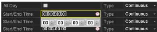
Figure 5-10 Edit Schedule- Set Time Period

- Up to 8 periods can be congured for each day. And the me periods cannot be overlapped with each other.
- To enable Event, Moon, Alarm, M | A (moon or alarm), M & A (moon and alarm) and POS triggered recording, you must congregate the moon detecon sengs, alarm input
sengs or VCA sengs as well. For detailed informaon, refer to Chapter 8.1, Chapter 8.7 and Chapter 9.
5) Repeat the above steps 1)-4) to schedule recording for other days in the week. If the schedule can also be set to other days, click Copy.

Figure 5-11 Copy Schedule to Other Days
i NOTE
The Holiday opon is available when you enable holiday schedule in Holiday sengs. See Chapter 5.7 Conguring Holiday Record.
6) Click OK to save seng and back to upper level menu.
Draw the schedule
1) Click on the color icon to select a record type in the event list on the right-side of the interface.
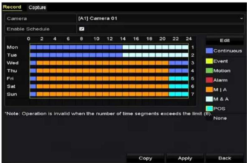
bar
| Day | Continuous | Event | Motion | Alarm | M/A | M & A | POS | |---|---|---|---|---|---|---|---| | Mon | 1 | 0 | 0 | 0 | 0 | 0 | 0 | | Tue | 2 | 0 | 0 | 0 | 0 | 0 | 0 | | Wed | 3 | 0 | 0 | 0 | 0 | 0 | 0 | | Thu | 4 | 0 | 0 | 0 | 0 | 0 | 0 | | Fri | 5 | 0 | 0 | 0 | 0 | 0 | 0 | | Sat | 6 | 0 | 0 | 0 | 0 | 0 | 0 | | Sun | 7 | 0 | 0 | 0 | 0 | 0 | 0 | *Note: Operation is invalid when the number of time segments exceeds the limit (8). Copy Apply BackFigure 5-12 Draw the Recording Schedule
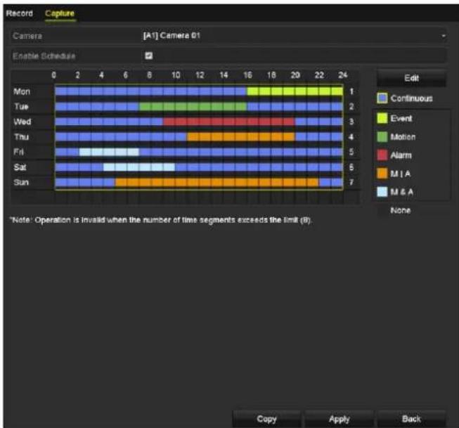
bar
| Day | Continuous | Event | Motion | Alarm | M I A | M & A | |---|---|---|---|---|---|---| | Mon | 1 | 0 | 0 | 0 | 0 | 0 | | Tue | 2 | 0 | 0 | 0 | 0 | 0 | | Wed | 3 | 0 | 0 | 0 | 0 | 0 | | Thu | 4 | 0 | 0 | 0 | 0 | 0 | | Fri | 5 | 0 | 0 | 0 | 0 | 0 | | Sat | 6 | 0 | 0 | 0 | 0 | 0 | | Sun | 7 | 0 | 0 | 0 | 0 | 0 | Note: Operation is invalid when the number of time segments exceeds the limit (8). Copy Apply BackFigure 5-13 Draw the Capture Schedule
2) Click and drag the mouse on the schedule.
3) Click on the other area except for the schedule table to nish and exit from the drawing.
You can repeat step 4 to set schedule for other channels. If the sengs can also be used to other channels, click Copy, and then choose the channel to which you want to copy to.
Step 5 Click Apply in the Record Schedule interface to save the sengs.
5.3 Configuring Motion Detection Recording and Capture
Purpose
Follow the steps to set the moon detecon parameters. In the live view mode, once a moon detecon event takes place, the DVR can analyze it and do many acons to handle it. Enabling moon detecon funcon can trigger certain channels to start recording, or trigger full screen monitoring, audio warning, nofying the surveillance center, sending email and so on.
Step 1 Enter the Moon Detecon interface.
Menu>Camera>Moon
![Motion Detection Camera [A1] Camera 01 Enable Motion Detection Settings Sensitivity Full Screen Clear](/content/2026/05/1005813/images/209773caa59a1647a28a73e138eb48fdb38fc900df251d49af9212f6a0ca47a4.jpg)
Figure 5-14 Moon Detecon
Step 2 Congure Moon Detecon:
1) Choose camera you want to congure.
2) Check the checkbox aer Enable Moon Detecon.
3) Drag and draw the area for moon detecon by mouse. If you want to set the moon detecon for all the area shot by the camera, click Full Screen. To clear the moon detecon area, click Clear.
![Motion Detection Camera [A1] Camera 01 Enable Motion Detection Settings Sensitivity Full Screen Clear](/content/2026/05/1005813/images/2025d8d5194d8f5d66627b3e3db514cb62baa8ba0554332d0b84e48e4148bd9e.jpg)
Figure 5-15 Moon Detecon-Mask
4) Click 📄, and the message box for channel informaon pops up.

Figure 5-16 Moon Detecon Sengs
5) Select the channels which you want the moon detecon event to trigger recording.
6) Click Apply to save the sengs.
7) Click OK to back to the upper level menu.
8) Exit the Moon Detecon menu.
Step 3 Congure the schedule.
Please refer to the step 4 of Chapter 5.2 Conguring Recording and Capture Schedule, while you may choose Moon as the record type.
5.4 Configuring Alarm Triggered Recording and Capture
Purpose
Follow the procedure to conjure alarm triggered recording or capture.
Step 1 Enter the Alarm Seng interface.
Menu > Conguraon > Alarm
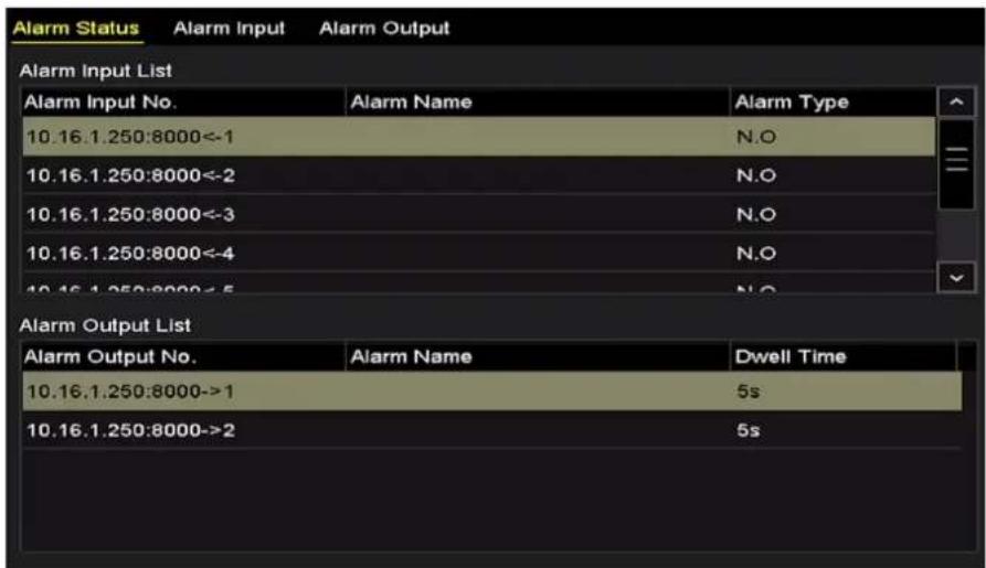
Figure 5-17 Alarm Sengs
Step 2 Click the Alarm Input tab.
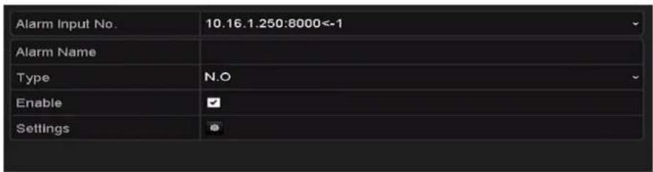
Figure 5-18 Alarm Sengs- Alarm Input
1) Select Alarm Input number and congure alarm parameters.
2) Choose N.O (normally open) or N.C (normally closed) for alarm type.
3) Check the checkbox of Seng.
4) Click the buon.

Figure 5-19 Alarm Handling
5) Choose the alarm triggered recording channel.
6) Check the checkbox to select channel.
7) Click Apply to save sengs.
8) Click OK to back to the upper level menu.
Repeat the steps from 1) to 8) to congure other alarm input parameters.
If the seng can also be applied to other alarm inputs, click Copy and choose the alarm input number.

Figure 5-20 Copy Alarm Input
Step 3 Congure the schedule.
Please refer to the step 4 of Chapter 5.2 Conguring Recording and Capture Schedule, while you may choose Alarm as the record type.
5.5 Configuring Event Recording and Capture
Purpose
The event triggered recording can be congured through the menu. Then events include the moon detecon, alarm and VCA events (face detecon/face capture, line crossing detecon, intrusion detecon, region entrance detecon, region exing detecon, loitering detecon, people gathering detecon, fast moving detecon, parking detecon, unaended baggage detecon,
object removal detecon, audio loss excepon detecon, sudden change of sound intensity detecon, and defocus detecon).
i NOTE
● The DS-7100 series DVR do not support the VCA alarm.
- DS-7200/7300/8100/9000HUHI-F/N series DVR support VCA (line crossing detecon and intrusion detecon) of all channels. DS-7600HUHI-F/N series DVR support 2-ch VCA (line crossing detecon and intrusion detecon). Channels with audio support audio excepon detecon.
- HQHI series DVR excluding 7100 series support 2-ch VCA (line crossing detecon and intrusion detecon). Channels with audio support audio excepon detecon.
- Other models support 1-ch VCA (line crossing detecon and intrusion detecon). Channels with audio support audio excepon detecon.
- For the analog channels, the line crossing detecon and intrusion detecon conict with other VCA detecon such as sudden scene change detecon, face detecon and vehicle detecon and heat map or people counting funcons. You can only enable one funcon.
Step 1 Enter the VCA sengs interface and select a camera for the VCA sengs.
Menu > Camera > VCA
![VCA Camera [A1] Camera 01 Face Detect... Vehicle Det... Line Cross... Intrusion De... Region Entr... Region Exit... Loitering D... People Gath... Fast Movin... Parking Det... Unattended... Object Rem... Audio Exce... Defocus De... Sudden Sc... Enable Settings Rule 1 Draw Line Draw Quadri... Clear All Rule Settings](/content/2026/05/1005813/images/84e2d652a844df4864c9defa45aaacc0dda912f25e12c46c6026f81f1b3fd3f0.jpg)
Figure 5-21 VCA Sengs
Step 2 Congure the detecon rules for VCA events. For details, see the step 6 in Chapter 10.3 Line Crossing Detecon.
Step 3 Click the icon 🙏 to conjure the alarm linkage actions for the VCA events.
Select Trigger Channel tab and select one or more channels which will start to record when VCA alarm is triggered.
Step 4 Click Apply to save the sengs.

Figure 5-22 Set Trigger Camera of VCA Alarm

The PTZ Linking funcon is only available for the VCA sengs of IP cameras.
Step 5 Enter Record Schedule Sengs interface (Menu>Record>Schedule>Record Schedule), and then set Event as the record type. For details, see step 2 in Chapter 5.2 Conguring Recording and Capture Schedule.
5.6 Configuring Manual Recording and Continuous Capture
Purpose
Follow the steps to set parameters for the manual recording and connuous capture. Using manual recording and connuous capture, you need to manually cancel the record and capture. The manual recording and manual connuous capture is prior to the scheduled recording and capture.
Step 1 Enter the Manual Record interface.
Menu > Manual

Figure 5-23 Manual Record
Step 2 Enable manual record.
Click the status icon before camera number to change it to . ON
Or click the status icon of Analog to enable manual record of all channels.
Step 3 Disable manual record.
Click the status icon
to change it to

Or click the status icon

sable manual record of all channels.

Aer reboong all the manual records enabled are canceled.
5.7 Configuring Holiday Recording and Capture
Purpose
Follow the steps to congregate the record or capture schedule on holiday for that year. You may want to have dierent plan for recording on holiday.
Step 1 Enter the Record seng interface.
Menu > Record
Step 2 Choose Holiday on the le bar.

Figure 5-24 Holiday Sengs
Step 3 Enable Edit Holiday schedule.
1) Click to enter the Edit interface.

Figure 5-25 Edit Holiday Sengs
2) Check the checkbox of Enable.
3) Select Mode from the dropdown list.
There are three dierent modes for the date format to congure holiday schedule. By Month, By Week, and By Date are selectable.
4) Set the start and end date.
5) Click Apply to save sengs.
6) Click OK to exit the Edit interface.
Step 4 Congure the record schedule.
Please refer to the Chapter 5.2 Conguring Recording and Capture Schedule, while you may choose Holiday in the Schedule dropdown list, or you can draw the schedule on the meline of Holiday.

Figure 5-26 Edit Schedule- Holiday
i NOTE
- Up to 8 periods can be congured for each day. And the me periods cannot be overlapped each other.
- In the me table of the channel, both holiday schedule and normal day schedule are displayed.
- Repeat the above step 4 to set Holiday schedule for other channels. If the holiday schedule can also be used to other channels, click Copy and choose the channel you want to apply the sengs.
5.8 Configuring Redundant Recording and Capture
Purpose
Enabling redundant recording and capture, which means saving the record les and captured pictures not only in the R/W HDD but also in the redundant HDD, will eecvely enhance the data safety and reliability.
Before you start
You must set the Storage mode in the HDD advanced sengs to Group before you set the HDD property to Redundant. For detailed informaon, please refer to Chapter 14.3 Managing HDD Group. There should be at least another HDD which is in Read/Write status.
Step 1 Enter HDD Informaon interface.
Menu> HDD
| Label | Capacity | Status | Property | Type | Free Space | Group | Edit | Delete |
| 1 | 931.51GB | Normal | R/W | Local | 865GB | 1 | - | |
| 3 | 931.51GB | Normal | R/W | Local | 931GB | 1 | - |
Figure 5-27 HDD General
Step 2 Select the HDD and click 📋 to enter the Local HDD Setngs interface.
1) Set the HDD property to Redundant.

Figure 5-28 HDD General-Eding
2) Click Apply to save the sengs.
3) Click OK to back to the upper level menu.
Step 3 Enter the Record seng interface.
Menu> Record> Parameters
1) Select the Record tab.
2) Select Camera you want to congure.
3) Click More Sengs buon.

Figure 5-29 More Sengs
4) Check the checkbox of Redundant Record.
5) Click OK to save the sengs.
6) If the encoding parameters can also be used to other channels, click Copy and choose the channel you want to apply the sengs.
5.9 Configuring HDD Group
Purpose
You can group the HDDs and save the record les in certain HDD group.
Step 1 Enter HDD seng interface.
Menu>HDD>Advanced
Step 2 Select Storage Mode tab.
Check whether the storage mode of the HDD is Group. If not, set it to Group. For detailed informaon, please refer to Chapter 14.3 Managing HDD Group.
Step 3 Select General in the le bar.
Click to enter eding interface.
Step 4 Conguring HDD group.
1) Choose a group number for the HDD group.
2) Click Apply to save your sengs.
3) Click OK to back to the upper level menu.
Step 5 Repeat the above steps to conjure more HDD groups.
Step 6 Choose the Channels which you want to save the record les in the HDD group.
1) Enter Storage Mode interface.
Menu>HDD>Advanced> Storage Mode

Figure 5-30 HDD Advanced
2) Choose Group number in the dropdown list of Record on HDD Group
3) Check the channels you want to save in this group.
4) Click Apply to save sengs.

Aer you have congured the HDD groups, you can congure the recording sengs following the procedure provided in Chapter 5.2-5.7.
5.10 Files Protection
Purpose
You can lock the recorded les or set the HDD property to Read-only to protect the record les from being overwrien.
Protect le by locking the record les
Step 1 Enter Export Sengs interface.
Menu> Export

Figure 5-31 Export
Step 2 Select the channels you want to investigate by checking the checkbox to .
Step 3 Congure the record mode, record type, le type, start me and end me.
Step 4 Click Search to show the results.

Figure 5-32 Export-Search Result
Step 5 Protect the record les.
1) Find the record les you want to protect, and then click the indicang that the le is locked.
icon which will turn to


The record les of which the recording is sll not completed cannot be locked.
2) Click 🔍 to change it to 🔍 to unlock the le and the le is not protected.
Protect le by seng HDD property to Read-only
Before you start
To edit HDD property, you need to set the storage mode of the HDD to Group. See Chapter 14.3 Managing HDD Group.
Step 1 Enter HDD seng interface.
Menu> HDD

Figure 5-33 HDD General
Step 2 Click to edit the HDD you want to protect.

Figure 5-34 HDD General- Eding
Step 3 Set the HDD to Read-only.
Step 4 Click OK to save sengs and back to the upper level menu.
i NOTE
- You cannot save any les in a Read-only HDD. If you want to save les in the HDD, change the property to R/W.
- If there is only one HDD and is set to Read-only, the DVR cannot record any les. Only live view mode is available.
- If you set the HDD to Read-only when the DVR is saving les in it, then the le will be saved in next R/W HDD. If there is only one HDD, the recording will be stopped.
5.11 One-Key Enabling and Disabling H.264+ for Analog Cameras
Purpose
For -F series DVR, you can one-key enable or disable H.264+ for the analog cameras.
Task 1: One-Key Enabling H.264+ for All Analog Cameras
Step 1 Enter the Record menu
Menu > Record
Step 2 Click Advanced to enter the Advanced Sengs interface.

Figure 5-35 Advanced Sengs (for HQHI and HGHI-F series DVR)

Figure 5-36 Advanced Sengs (for HUHI series DVR)
Step 3 Click Enable to enable H.264+ for all the analog cameras and the following attenon box pops up.

Figure 5-37 Aenon Box
Step 4 Click Yes to enable the funcon and reboot the device to have new sengs taken effect.

If H.264+ is already enabled for all the analog cameras, when you click Enable buon, the following aenon box pops up to remind you that H.264+ is already enabled for all analog cameras.
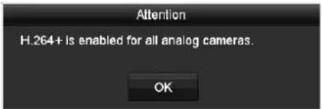
Figure 5-38 Aenon Box
Task 2: One-Key Disabling H.264+ for All Analog Cameras
Step 1 Enter the Record menu
Menu > Record
Step 2 Click Advanced to enter the advanced interface.

Figure 5-39 Advanced Sengs (for HQHI and HGHI-F series DVR)
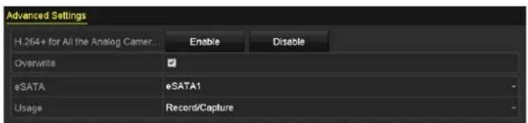
Figure 5-40 Advanced Sengs (for HUHI series DVR)
Step 3 Click Disable to disable H.264+ for all the analog cameras and the following attenon box pops up.

Figure 5-41 Aenon Box
Step 4 Click Yes to enable the funcon and reboot the device to have new sengs taken effect.

If H.264+ is already disabled for all the analog cameras, when you click Disable buon, the following aenon box pops up to remind you that H.264+ is already disabled for all analog cameras.
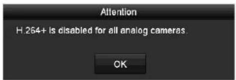
Figure 5-42 Aenon Box
5.12 Configuring 1080P Lite
Purpose
When the 1080P Lite Mode is enabled, the encoding resolution at 1080P Lite (real-me) is supported. If not, up to 1080P (non-real-me) is supported.

This secon is applicable to HQHI and HGHI-F series DVR.
● For HQHI series DVR:
Task1: Enabling the 1080P Lite Mode
Step 1 Enter the Record menu
Menu > Record
Step 2 Click Advanced to enter the advanced interface.

Figure 5-43 Advanced Interface (for DS-7100/7200HQHI-F/N)
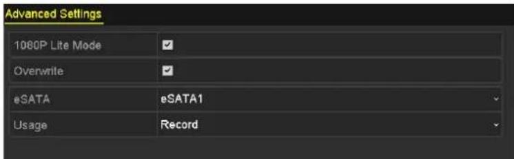
Figure 5-44 Advanced Interface (for DS-7300/8100HQHI-F/N)
Step 3 Check the checkbox of 1080P Lite Mode and click Apply to pop up the aenon box. Aer enabling 1080p lite mode, the 3 MP signal is not accessible to analog channel.

Figure 5-45 Attenon
Step 4 Click Yes to reboot the device to have new sengs taken eect.
Task2: Disabling the 1080P Lite Mode
Step 1 Enter the Record menu
Menu > Record
Step 2 Click Advanced to enter the advanced interface.
Step 3 Uncheck the checkbox of 1080P Lite Mode and click Apply. The following aenon box pops up:
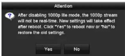
Figure 5-46 Aenon
Step 4 Click Yes to reboot the device to acvate the new sengs or No to restore the old sengs.
● For HGHI-F series DVR:
Task1: Enabling the 1080P Lite Mode
Step 1 Enter the Record menu
Menu > Record
Step 2 Click Advanced to enter the advanced interface.

Figure 5-47 Advanced Interface (for HGHI-F Series DVR)
Step 3 Check the checkbox of 1080P Lite Mode and click Apply to pop up the aenon box. Enabling 1080p lite will switch to real-me mode.

Figure 5-48 Enable 1080P Lite
Step 4 Click Yes to reboot the device to enable 1080p lite mode and the encoding mode will change to real-me mode.
Task2: Disabling the 1080P Lite Mode
Step 1 Enter the General Conguraon interface.
Menu > Conguraon > General
Step 2 Click More Sengs to enter the More Sengs interface.

Figure 5-49 More Sengs
Step 3 Select the Encoding Mode to Non-Real-Time Mode.
Step 4 Click Apply to pop up the aenon box. Enabling non-real-me encoding will disable 1080p lite mode.

Figure 5-50 Disable 1080P Lite
Step 5 Click Yes to reboot the device to disable 1080p lite mode.
Chapter 6 Playback
6.1 Playing Back Record Files
6.1.1 Instant Playback
Purpose
Play back the recorded video les of a speci channel in the live view mode. Channel switch is supported.
Instant playback by channel
Choose a channel in live view mode and click the 📄ion in the quick seng toolbar.

In the instant playback mode, only record les recorded during the last ve minutes on this channel will be played back.

natural_image
Four-panel composite image showing a multi-lane highway with vehicles and traffic, no visible text or symbols.Figure 6-1 Instant Playback Interface
6.1.2 Playing Back by Normal Search
Playback by Channel
Enter the Playback interface.
Right click a channel in live view mode and select Playback from the menu, as shown in the following gure:

Figure 6-2 Right-click Menu under Live View
Playback by Time
Purpose
Play back video les recorded in specied me duraon. Mul-channel simultaneous playback and channel switch are supported.
Step 1 Enter Playback interface.
Menu>Playback
Step 2 Check the checkbox of channel(s) in the channel list and then double-click to select a date on the calendar.

Figure 6-3 Playback Calendar

If there are record les for that camera in that day, in the calendar, the icon for that day is displayed as . Otherwise it is displayed as .
Playback Interface
You can select the main stream or sub stream from the dropdown list for playback.
You can also use the toolbar in the boom part of Playback interface to control playing progress, as shown in the following gure.

Figure 6-4 Playback Interface
Select the channel(s) if you want to switch playback to another channel or execute simultaneous playback of mulple channels.

Figure 6-5 Toolbar of Playback
Table 6-1 Detailed Explanaon of Playback Toolbar
| Button | Operation | Button | Operation | Button | Operation |
 | Audio on/Mute |  | Start/Stop clipping | [×7C0] | Lock File |
| [DBYA] | Add default tag | [T020] | Add customized tag | [23C2] | File management for video clips, locked les andtags |
 | Reverse play/Pause | [0AH8] | Stop |  | Digital Zoom |
| [5XCH] | 30s forward |  | 30s reverse |  | Pause/Play |
 | Fast forward |  | Previous day |  | Slow forward |
| [C0XH] | Full Screen | [YX03] | Exit | [04ZB] | Next day |
| [H00D] | Save the clips |  | Process bar |  | Scaling up/down the me line |
| [X0HX] | Enable/Disable POS informaon overlay |
i NOTE
This enable/disable POS overlay funcon is supported by DS-7300/8100HQHI-F/N and DS-7300/8100/9000HUHI-F/N series DVR only. When the POS is enabled when playing back, the POS informaon will be overlain on the video. And the keyword searching is supported.
i NOTE
● The 01-02-2015 00:13:24:14:07:2015 16:18:47 me of the record les.
- represents normal recording (manual or schedule); represents event recording (moon, alarm, moon | alarm, moon & alarm).
- Playback progress bar: use the mouse to click any point of the progress bar to locate special frames.
6.1.3 Playing Back by Event Search
Purpose
Play back record les on one or several channels searched out by restrictive event type (moon detecon, alarm input or VCA). Channel switch is supported.
Step 1 Enter the Playback interface.
Menu>Playback
Step 2 Click an Closecheck to enter the Event Playback interface.
Step 3 Select Alarm Input, Moon, VCA as the event type, and specify the start me and end me for search.

Figure 6-6 Video Search by Moon Detecon
Step 4 Click Search, and the record les matching the search conditions will be displayed on a list.
Step 5 Select and click buon to play back the record les.
You can click Back buon to return to the search interface.
If there is only one channel triggered, clicking 📄uon takes you to Full-screen Playback interface of this channel.
If several channels are triggered, clicking 📋 buon takes you to the Synchronous Playback interface. Check ⚙ checkbox to select one channel for playback or select mulple channels for synchronous playback.

The maximum number of channels for synchronous playback supported varies to dierent models.

Figure 6-7 Select Channels for Synchronous Playback
Step 6 On the Event Playback interface, you can select the main stream or sub-stream from the dropdown list for playback.
The toolbar in the boom part of Playback interface can be used to control playing process.
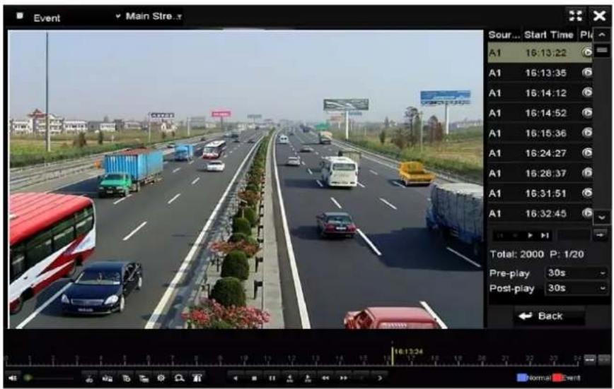
Figure 6-8 Interface of Playback by Event
Pre-play and post-play can be congured for the playback of event triggered record les.
Pre-play: The me you set to play back before the event. For example, when an alarm triggered the recording at 10:00, if you set the pre-play me as 5 seconds, the video plays back from 9:59:55.
Post-play: The me you set to play back aer the event. For example, when an alarm triggered the recording ends at 11:00, if you set the post-play me as 5 seconds, the video plays back II 11:00:05.
Step 7 You can click < or > button to select the previous or next event. Please refer to Table 6-1 for the descripon of buons on the toolbar.
6.1.4 Playing Back by Tag
Purpose
Video tag allows you to record related informaon like people and locaon of a certain me point during playback. You are also allowed to use video tag(s) to search for record les and posion me point.
Before playing back by tag
Step 1 Enter Playback interface.
Menu>Playback
Step 2 Search and play back the record le(s). Refer to Chapter 6.1.2 Playing Back by Normal Search for the detailed informaon about searching and playback of the record les.

Figure 6-9 Interface of Playback by Time
Click ☐ uon to add default tag.
Click ☐ uon to add customized tag and input tag name.
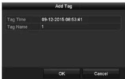
Figure 6-10 Add Tag

Max. 64 tags can be added to a single video le.
Step 3 Tag management.
Click 📁uon to check, edit and delete tag(s).

Figure 6-11 Tag Management Interface
Steps
Step 1 Select Tag from the drop-down list in the Playback interface.
Step 2 Choose channels, edit start me and end me, and then click Search to enter Search Result interface.

NOTE
You can enter keyword in the textbox Keyword search the tag on your command.

Figure 6-12 Video Search by Tag
Step 3 Click 📞uon to play back the le.
You can click the Back buon to return to the search interface.
i NOTE
● Pre-play and post-play can be congured.
- You can click
6.1.5 Playing Back by Smart Search
Purpose
The smart playback funcon provides an easy way to get through the less eecve informaon. When you select the smart playback mode, the system will analyze the video containing the moon or VCA informaon, mark it with green color and play it in the normal speed while the video without moon will be played in the 16-me speed. The smart playback rules and areas are congorable.
Before you start
To get the smart search result, the corresponding event type must be enabled and congured on the IP camera. Here we take the intrusion detecon as an example.
Step 1 Log in the IP camera by the web browser, and enable the intrusion detecon by checking the checkbox of it. You may enter the moon detecon conguraon interface by Conguraon > Advanced Conguraon > Events > Intrusion Detecon.

Figure 6-13 Seng Intrusion Detecon on IP Camera
Step 2 Congure the required parameters of intrusion detecon, including area, arming schedule and linkage methods. Refer to the user manual of smart IP camera for detailed instrucons.
Steps
Step 1 Enter the Playback interface.
Menu>Playback
Step 2 Select the Smart in the drop-down list on the top-le side.
Step 3 Select a camera in the camera list.

Figure 6-14 Smart Playback Interface
Step 4 Select a date in the calendar and click the 📞uon to play.
Refer to Table 6-2 for the descripons of the buons on the Smart Playback Toolbar.
Table 6-2 Detailed Explanaon of Smart Playback Toolbar
| Button | Operation | Button | Operation | Button | Operation |
 | Draw line for the line crossing detecon |  | Draw quadrilateral for the intrusion detecon |  | Draw rectangle for the intrusion detecon |
 | Set full screen for moon detecon |  | Clear all |  | Start/Stop clipping |
 | File management for video clips |  | Stop playing |  | Pause playing /Play |
 | Smart sengs |  | Search matched video les |  | Filter video les by seng the targetcharacters |
Step 5 Set the rules and areas for smart search of VCA event or moon event.
● Line Crossing Detecon
Select the ☐ion, and click on the image to specify the start point and end point of the line.
- Intrusion Detecon
Click the ☐ion, and specify 4 points to set a quadrilateral region for intrusion detecon. Only one region can be set.
- Moon Detecon
Click the ☐ion and then click and draw the mouse to set the detecon area manually. You can also click the ☐ion to set the full screen as the detecon area.
Step 6 Click ☐ congregate the smart sengs.

Figure 6-15 Smart Sengs
Skip the Non-Related Video: The non-related video will not be played if this funcon is enabled.
Play Non-Related Video at: Set the speed to play the non-related video. Max. 8/4/2/1 are selectable.
Play Related Video at: Set the speed to play the related video. Max. 8/4/2/1 are selectable.

Pre-play and post-play is not available for the moon event type.
Step 7 Click search and play the matched video les.
Step 8 (Oponal) You can click the searched video les by seng the target characters, including the gender and age of the human and whether he/she wears glasses.

Figure 6-16 Set Result Filter

The Result Filter funcon is supported by the IP camera only.
6.1.6 Playing Back by System Logs
Purpose
Play back record le(s) associated with channels aer searching system logs.
Step 1 Enter Log Informaon interface.
Menu>Maintenance>Log Informaon

Figure 6-17 System Log Search Interface
Step 2 Click Log Search tab to enter System Log Search interface.
Set search me and type and click Search buon.

Figure 6-18 Result of System Log Search
Step 3 Choose a log with record le and click 📋buon to enter Playback interface.

If there is no record le at the me point of the log, the message box "No result found" will pop up.
Step 4 Playback management.
The toolbar in the boom part of Playback interface can be used to control playing process.
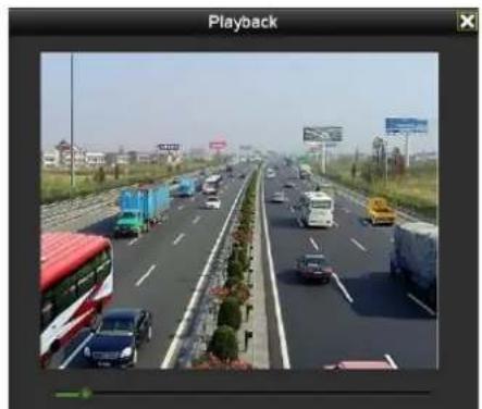
natural_image
Highway scene with multiple vehicles and a red double-decker bus, no visible text or symbols on the road or vehicles.Figure 6-19 Interface of Playback by Log
6.1.7 Playing Back by Sub-Periods
Purpose
The video les can be played in mulple sub-periods simultaneously on the screens.
Step 1 Enter Playback interface.
Menu>Playback
Step 2 Select Sub-periods from the drop-down list in the upper-le corner of the page to enter the Sub-periods Playback interface.
Step 3 Select a date and start playing the video le.
Step 4 Select the Split-screen Number from the dropdown list. Up to 16 screens are congorable.

Figure 6-20 Interface of Sub-periods Playback
i NOTE
According to the dened number of split-screens, the video les on the selected date can be divided into average segments for playback. E.g., if there are video les exisng between 16:00 and 22:00, and the 6-screen display mode is selected, then it can play the video les for 1 hour on each screen simultaneously.
6.1.8 Playing Back External File
Purpose
Perform the following steps to look up and play back les in the external devices.
Step 1 Enter the Playback interface.
Menu>Playback
Step 2 Select the External File in the drop-down list on the top-le side.
The les are listed in the right-side list.
You can click the Refresh the le list.
Step 3 Select and click the buon to play back it.

Figure 6-21 Interface of External File Playback
6.1.9 Playing Back Pictures

The playback by picture is supported by the DS-7300/8100/9000HUHI-F/N series DVR only.
Purpose
The captured pictures stored in the HDDs of the device can be searched and viewed.
Step 2 Enter Playback interface.
Menu>Playback
Step 3 Select Picture from the drop-down list in the upper-le corner of the page to enter the Picture Playback interface.
Step 4 Check checkbox to select the channel(s) and specify the start me and end me for search.
Step 5 Click Search to enter Search Result interface.

Up to 4000 pictures can be displayed each me.
Step 6 Choose a picture you want to view and click buon.
You can click Back to return to the search interface.

Figure 6-22 Result of Picture Playback
Step 7 The toolbar in the boom part of Playback interface can be used to control playing process.

Figure 6-23 Picture Playback Toolbar
Table 6-3 Detailed Explanaon of Picture-playback Toolbar
| Button | Function | Button | Function | Button | Function | Button | Function |
| Play reverse | Play | Previous picture | Next picture |
6.2 Auxiliary Functions of Playback
6.2.1 Playing Back Frame by Frame
Purpose
Play video les frame by frame, in order to check image details of the video when abnormal events happen.
Step 1 Go to Playback interface and click buon 📁 unl the speed changes to Single frame.
Step 2 One click on the playback screen represents playback or adverse playback of one frame. You can use buon i-toobar to stop the playing.
6.2.2 Digital Zoom
Step 1 Click the 📄 quon on the playback control bar to enter Digital Zoom interface.
Step 2 Use the mouse to draw a red rectangle and the image within it will be enlarged up to 16 mes.

natural_image
Highway scene with vehicles and shipping containers, residential buildings in background (no visible text or symbols)Figure 6-24 Draw Area for Digital Zoom
Step 3 Right-click the image to exit the digital zoom interface.
6.2.3 Reverse Playback of Multi-Channel
Purpose
You can play back record les of mul-channel reversely. Up to 16-ch simultaneous reverse playback is supported.
Step 1 Enter Playback interface.
Menu>Playback
Step 2 Check more than one checkboxes to select mulple channels and click to select a date on the calendar.
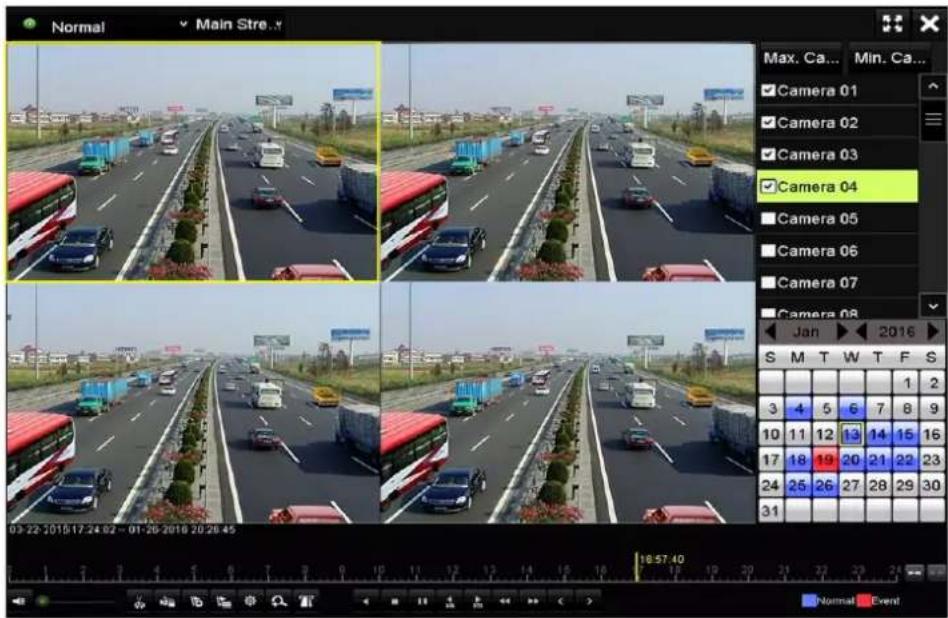
Figure 6-25 4-ch Synchronous Playback Interface
Step 3 Click play back the record les reversely.
Chapter 7 Backup
7.1 Backing up Record Files
Before you start
Please insert the backup device(s) into the device.
7.1.1 Backing up by Normal Video/Picture Search
Purpose
The record les or pictures can be backed up to various devices, such as USB devices (USB ash drives, USB HDDs, USB writer), SATA writer and e-SATA HDD.
Backup using USB ash drives and USB HDDs
Step 1 Enter Export interface.
Menu>Export>Normal/Picture
Step 2 Select the cameras to search.
Step 3 Set search condion and click Search buon to enter the search result interface.

The POS record type is supported by DS-7300/8100HQHI-F/N and DS-7300/8100/9000HUHI-F/N series DVR only.

Figure 7-1 Normal Video Search for Backup
Step 4 The matched video les are displayed in Chart or List display mode.
Click to play the record le if you want to check it.
Check the checkbox before the video les you want to back up.

The size of the currently selected les is displayed in the lower-le corner of the window.

Figure 7-2 Result of Normal Video Search for Backup
Step 5 Select video les from the Chart or List to export, and click the buon Export to enter the Export interface.
You can also click Export All to select all the video les for backup and enter the Export interface.
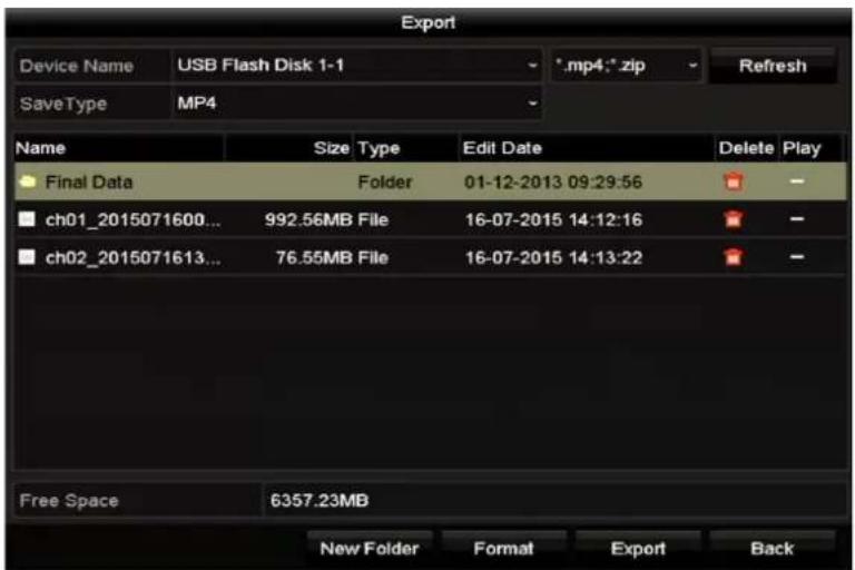
Figure 7-3 Export by Normal Video Search using USB Flash Drive
Step 6 Select the backup device from the drop-down list and you can also select the le format to liter the les exisng in the backup device.
Step 7 Select the saving type.
Step 8 Click the buon Export on the Export interface to start the backup process. On the pop-up message box, select to export the video les or the player to the backup device. Click OK to conrm.

Figure 7-4 Select File or Player for Backup
Step 9 A prompt message will pop up aer the backup process is complete. Click OK to conrm.
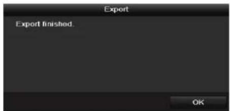
Figure 7-5 Export Finished

The backup of pictures using USB writer or SATA writer has the same operang instrucons. Please refer to steps described above.
7.1.2 Backing up by Event Search
Purpose
Back up event-related record les using USB devices (USB ash drives, USB HDDs, USB writer), SATA writer or eSATA HDD. Quick Backup and Normal Backup are supported.
Step 1 Enter Export interface.
Menu > Export > Event
Step 2 Select the cameras to search.
Step 3 Select the event type to alarm input, moon, VCA or POS (for DS-7300/8100HQHI-F/N and DS-7300/8100/9000HUHI-F/N series DVR only).

Figure 7-6 Event Search for Backup
Step 4 Set search condion and click Search buon to enter the search result interface. The matched video les are displayed in Chart or List display mode.
Step 5 Select video les from the Chart or List interface to export.

Figure 7-7 Result of Event Search
Step 6 Export the video les. Please refer to step5 of Chapter 7.1.1 Backing up by Normal Video/Picture Search for details.
7.1.3 Backing up Video Clips
Purpose
You may also select video clips in playback mode to export directly during Playback, using USB devices (USB ash drives, USB HDDs, USB writer), or SATA writer.
Step 1 Enter Playback interface.
Step 2 During playback, use buons on in the playback toolbar to start or stop clipping record le(s).
Step 3 Click enter the le management interface.

Figure 7-8 Video Clips Export Interface
Step 4 Export the video clips in playback. Please refer to step5 of Chapter 7.1.1 Backing up by Normal Video/Picture Search for details.
7.2 Managing Backup Devices
Management of USB ash drives, USB HDDs and eSATA HDDs
Step 1 Enter the Export interface.

Figure 7-9 Storage Device Management
Step 2 Backup device management.
Click New Folder buon if you want to create a new folder in the backup device.
Select a record le or folder in the backup device and click button on if you want to delete it.
Click Erase buon if you want to erase the les from a re-writable CD/DVD.
Click Format buon to format the backup device.

If the inserted storage device is not recognized:
- Click the Refresh buon.
● Reconnect device. - Check for compatibility from vendor.
Chapter 8 Alarm Settings
8.1 Setting Motion Detection
Step 1 Enter Moon Detecon interface of Camera Management and choose a camera you want to set up moon detecon.
Menu> Camera> Moon
![Motion Detection Camera [D1] IPdome Enable Motion Detection Settings Sensitivity Full Screen Clear](/content/2026/05/1005813/images/b7ba57c6a2c8e80dee6b2ba94e87c1383f89e6cd326f7db9e23c63c4f0c59824.jpg)
Figure 8-1 Moon Detecon Setup Interface
Step 2 Set detecon area and sensitivity.
Check checkbox to enable moon detecon. Use the mouse to draw detecon area(s) or click Full Screen to set the detecon area to be the full screen and drag the sensitivity bar to set sensitivity.
Click 📄 to set alarm response acons.
![Motion Detection Camera [A1] Camera 01 Enable Motion Detection Settings Sensitivity Full Screen Clear](/content/2026/05/1005813/images/0cc201a2614ca626249168d1b476143451aeb9b2ce3ca578628a0ab99e5728b6.jpg)
Figure 8-2 Set Detecon Area and Sensitivity
Step 3 Click Trigger Channel tab and select one or more channels which will start to record or become full-screen monitoring when moon alarm is triggered.

Figure 8-3 Set Trigger Camera of Moon Detecon
Step 4 Set arming schedule of the channel.
Select Arming Schedule tab to set the channel's arming schedule.
Choose one day of a week and up to eight me periods can be set within each day. Or you can click the Copy buon to copy the me period sengs to other day(s).

Time periods shall not be repeated or overlapped.

Figure 8-4 Set Arming Schedule of Moon Detecon
Step 5 Click Linkage Acon tab to set up alarm response acons of moon alarm (please refer to Chapter 8.7 Seng Alarm Response Acons).
Repeat the above steps to set up arming schedule of other days of a week.
Click the OK buon to complete the moon detecon sengs of the channel.
Step 6 If you want to set moon detecon for another channel, repeat the above steps or just copy the above sengs to it.

You are not allowed to copy the "Trigger Channel" acon.
8.2 Setting Sensor Alarms
Purpose
Set up handling method of an external sensor alarm.
Step 1 Enter Alarm Sengs of System Conguraon and select an alarm input.
Menu> Conguraon> Alarm
Select Alarm Input tab to enter Alarm Input Sengs interface.

Figure 8-5 Alarm Status Interface of System Conguraon
Step 2 Set the handling method of the selected alarm input.
Check the Enable checkbox and click 📄uon to set its alarm response acons.

Figure 8-6 Alarm Input Sengs Interface
Step 3 Select Trigger Channel tab and select one or more channels which will start to record or become full-screen monitoring when an external alarm input is triggered.
Step 4 Select Arming Schedule tab to set the channel's arming schedule.
Choose one day of a week and max. eight me periods can be set within each day.

Time periods shall not be repeated or overlapped.
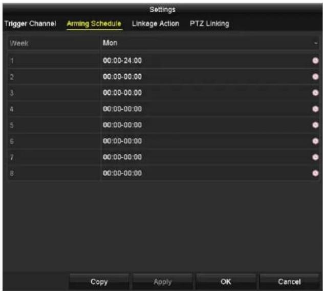
Figure 8-7 Set Arming Schedule of Alarm Input
Step 5 Select Linkage Acon tab to set up alarm response acons of the alarm input (please refer to Chapter 8.7 Seng Alarm Response Acons).
Repeat the above steps to set up arming schedule of other days of a week. You can also use Copy buon to copy an arming schedule to other days.
Step 6 If necessary, select PTZ Linking tab and set PTZ linkage of the alarm input.
Set PTZ linking parameters and click the OK buon to complete the sengs of the alarm input.

Please check whether the PTZ or speed dome supports PTZ linkage.
One alarm input can trigger presets, patrol or paern of more than one channel. But presets, patrols and paerns are exclusive.
![Settings Trigger Channel Arming Schedule Linkage Action PTZ Linking PTZ Linking [A1] Camera 01 Call Preset Preset 1 Call Patrol Patrol 1 Call Pattern Pattern 1 Apply OK Cancel](/content/2026/05/1005813/images/38312620044e7baa1fd63ad57eae8f3ae8e9aaac35f5b0c4729f96e130b789e9.jpg)
Figure 8-8 Set PTZ Linking of Alarm Input
Step 7 If you want to set handling acon of another alarm input, repeat the above steps or just copy the above sengs to it.

Figure 8-9 Copy Sengs of Alarm Input
8.3 Detecting Video Loss
Purpose
Detect video loss of a channel and take alarm response acon(s).
Step 1 Enter Video Loss interface of Camera Management and select a channel you want to detect.
Menu> Camera> Video Loss
![Video Loss Camera [A1] Camera 01 Enable Video Loss Alarm Settings](/content/2026/05/1005813/images/21a3578227c961be5c27221ec26c15fd2fc63a92ad692285ba87857d8bce6811.jpg)
Figure 8-10 Video Loss Setup Interface
Step 2 Set up handling method of video loss.
Check the checkbox of Enable Video Loss Alarm.
Click 📄 on to set up handling method of video loss.
Step 3 Set arming schedule of the channel.
Select Arming Schedule tab to set the channel's arming schedule.
Choose one day of a week and up to eight me periods can be set within each day. Or you can click the Copy buon to copy the me period sengs to other day(s).

Time periods shall not be repeated or overlapped.

Figure 8-11 Set Arming Schedule of Video Loss
Repeat the above steps to set arming schedule of other days of a week. You can also use Copy buon to copy an arming schedule to other days.
Step 4 Select Linkage Acon tab to set up alarm response acon of video loss (please refer to Chapter 8.7 Seng Alarm Response Acons).
Step 5 Click the OK buon to complete the video loss sengs of the channel.
Repeat the above steps to nish sengs of other channels, or click the Copy buon copy the above sengs to them.
8.4 Detecting Video Tampering
Purpose
Trigger alarm when the lens is covered and take alarm response acon(s).
Step 1 Enter Video Tampering interface of Camera Management and select a channel you want to detect video tampering.
Menu> Camera> Video Tampering Detecon
![Video Tampering Detection Settings Camera [D1] IPdome Enable Video Tampering Detect... Settings Sensitivity](/content/2026/05/1005813/images/55f29cad67e7b45e2bb8796d02fa91a4f60107c1fd89c2f87e9c1f3d51a54d2d.jpg)
Figure 8-12 Video Tampering Interface
Step 2 Check the checkbox of Enable Video Tampering Detecon.
Step 3 Drag the sensitivity bar and choose a proper sensitivity level.
Step 4 Click 📋 set handling method of video tampering. Set arming schedule and alarm response acons of the channel.
1) Click Arming Schedule tab to set the arming schedule of response acon.
2) Choose one day of a week and up to eight me periods can be set within each day.

Time periods shall not be repeated or overlapped.

Figure 8-13 Set Arming Schedule of Video Tampering
3) Select Linkage Acon tab to set alarm response acons of video tampering alarm (please refer to Chapter 8.7 Seng Alarm Response Acons).
Repeat the above steps to set arming schedule of other days of a week. You can also use Copy buon to copy an arming schedule to other days.
4) Click the OK buon to complete the video tampering sengs of the channel.
Repeat the above steps to nish sengs of other channels, or click the Copy buon copy the above sengs to them.
Step 5 Click the Apply buon to save and acvate the sengs.
8.5 Setting All-day Video Quality Diagnostics
Purpose
The device provides two ways to diagnose the video quality: manual and all-day. Perform the following steps to set the threshold of the diagnosing and the linkage acons.
Step 1 Enter Video Quality Diagnoscs Sengs interface of Camera Management and select a channel you want to detect video tampering.
Menu> Camera> Video Quality Diagnoscs
![Video Quality Diagnostics Camera [A1] Camera 01 Enable Video Quality Diagnostics Settings Diagnostics Mode Threshold Blurred Im... 60 ° Abnormal ... 55 ° Color Cast 60 °](/content/2026/05/1005813/images/4aea374040505e929b4711d04f6fa13341ec2e6843bdcdbff3abfee2ae473eeb.jpg)
Figure 8-14 Video Quality Diagnoscs Interface
Step 2 Check the checkbox of Enable Video Quality Diagnoscs.
i NOTE
To enable video quality diagnoses, the funcon should be supported by the selected camera.
Step 3 Enable and set the threshold of the diagnostic types, there are Blurred Image, Abnormal Brightness, and Color Cast.
Check the corresponding checkbox of the diagnostic type, and adjust the threshold of it by dragging the bar.
i NOTE
The higher the threshold you set, the harder the excepon will be detected.
Step 4 Click 📋 set handling method of video quality diagnoses. Set arming schedule and alarm response acons of the channel.
1) Click Arming Schedule tab to set the arming schedule of response acon.
2) Choose one day of a week and up to eight me periods can be set within each day.
i NOTE
Time periods shall not be repeated or overlapped.

Figure 8-15 Set Arming Schedule of Video Quality Diagnoscs
3) Select Linkage Acon tab to set alarm response acons of video quality diagnoses alarm (please refer to Chapter 8.7 Seng Alarm Response Acons).
Repeat the above steps to set arming schedule of other days of a week. You can also use Copy buon to copy an arming schedule to other days.
4) Click the OK buon to complete the video quality diagnoses sengs of the channel.
Step 5 Click the Apply buon to save and acvate sengs.
Step 6 (Oponal) you can copy the same sengs to other cameras by clicking the Copy buon.
8.6 Handling Exceptions
Purpose
Excepon sengs refer to the handling method of various excepons, e.g.
- HDD Full: The HDD is full.
- HDD Error: Wring HDD error, unformaed HDD, etc.
● Network Disconnected: Disconnected network cable.
● IP Conicted: Duplicated IP address. - Illegal Login: Incorrect user ID or password.
- Input/Recording Resoluon Mismatch: The input resoluon is smaller than the recording resoluon.
- Record/Capture Excepon: No space for saving recorded les or captured pictures.
Step 1 Enter Excepons interface and handle various excepons.
Menu> Conguraon> Excepons

Figure 8-16 Excepon Sengs Interface
Step 2 Check the checkbox of Enable Event Hint to display the 🔒 (Event/Excepon icon) when an excepconal event occurs. And click the icon ⚫ select the detailed event hint for display.

Figure 8-17 Event Hint Sengs
i NOTE
Click the icon 🖼 appears in the live view interface, and you can view the detailed informaon of the excepconal event. Click the button Set, and then you can select the detailed event hint for display.

Figure 8-18 Detailed Event
Step 3 Set the alarm linkage acons. For details, see Chapter 8.7 Seng Alarm Response Acons.
Step 4 Click Apply to save the sengs.
8.7 Setting Alarm Response Actions
Purpose
Alarm response acons will be acvated when an alarm or excepon occurs, including Full Screen Monitoring, Audible Warning (buzzer), Nofy Surveillance Center, Send Email and Trigger Alarm Output.
Full Screen Monitoring
When an alarm is triggered, the local monitor (HDMI, VGA or CVBS monitor) displays in full screen the video image from the alarming channel congured for full screen monitoring.
If alarms are triggered simultaneously in several channels, their full-screen images will be switched at an interval of 10 seconds (default dwell me). A dierent dwell me can be set by going to Menu > Conguraon > Live View.
Auto-switch will terminate once the alarm stops and you will be taken back to the Live View interface.
Audible Warning
Trigger an audible beep when an alarm is detected.
Nofy Surveillance Center
Sends an exception or alarm signal to remote alarm host when an event occurs. The alarm host refers to the PC installed with Remote Client.

The alarm signal will be transmied automacally at detecon mode when remote alarm host is congured. Please refer to Chapter 12.2.6 Conguring More Sengs for details of alarm host conguraon.
Send Email
Send an email with alarm informaon to a user or users when an alarm is detected.
Please refer to Chapter 12.2.8 Conguring Email for details of Email conguraon.
Trigger Alarm Output
Trigger an alarm output when an alarm is triggered.
Step 1 Enter Alarm Output interface.
Menu> Conguraon> Alarm> Alarm Output
Select an alarm output and set alarm name and dwell me.

Figure 8-19 Alarm Output Sengs Interface

If Manually Clear is selected in the dropdown list of Dwell Time, you can clear it only by going to Menu> Manual> Alarm.
Step 2 Click button to set the arming schedule of alarm output.
Choose one day of a week and up to 8 me periods can be set within each day.

Time periods shall not be repeated or overlapped.

Figure 8-20 Set Arming Schedule of Alarm Output
Step 3 Repeat the above steps to set arming schedule of other days of a week. You can also click Copy buon to copy an arming schedule to other days.
Click the OK buon to complete the arming schedule seng of alarm output.
Step 4 Click the Apply buon to save the sengs.
Chapter 9 POS Configuration

This chapter is applicable to DS-7300/8100HQHI-F/N and DS-7300/8100/9000HUHI-F/N series DVR only.
9.1 Configuring POS Settings
Step 1 Enter the POS sengs interface.
Menu > Conguraon > POS > POS Sengs
Step 2 Select the POS from the drop-down list. Up to 8 POS units are selectable.
Step 3 Check the checkbox to enable the POS funcon.

Figure 9-1 POS Sengs
Step 4 Filter the POS privacy informaon if needed.
1) Click aer Privacy Sengs to enter POS Privacy Informaon Filtering interface.

Figure 9-2 POS Privacy Informaon Filtering
2) Edit the Privacy Informaon in the text led to hide the input informaon overlay. Up to 3 pieces of privacy informaon can be edited and no more than 32 characters can be input for each piece of informaon.
3) Click OK to save the sengs.
Step 5 Select the POS protocol to Universal Protocol, EPSON, AVE or NUCLEUS.
● Universal Protocol
Click the Advanced buon to expand more sengs when selecng the universal protocol. You can set the start line tag, line break tag and end line tag for the POS overlay characters, and the case-sensitive property of the characters.
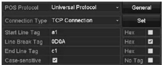
Figure 9-3 Universal Protocol Sengs
- NUCLEUS
If you select NUCLEUS protocol, reboot the device to take the new sengs into eect.

Figure 9-4 NUCLEUS Protocol Sengs
1) Click Set buon to enter the NUCLEUS Sengs interface.

Figure 9-5 NUCLEUS Sengs
2) Edit the Employee, Shi and Terminal informaon. No more than 32 characters can be input.
3) Click OK to save the sengs.

- If you select NUCLEUS protocol, the conncon type defaults to be RS-232, and all the other POS protocol will change to be NUCLEUS.
- You should set Usage to be Transparent Channel for RS-232 sengs in Menu > Conguraon > RS-232 rst.
Step 6 Select the Connecon Type to TCP, UDP, Mulcast, RS-232, USB->RS-232 or Sni, and click Set to congregate the parameters for each connecon type.
- TCP Connecon
When using TCP conncon, the port must be set from 0 to 65535, and the port for each POS machine must be unique. Input the Allowed Remote IP Address for connecng the DVR and the POS machine via TCP.

Figure 9-6 TCP Connecon Sengs
- UDP Connecon
When using UDP conncon, the port must be set from 0 to 65535, and the port for each POS machine must be unique. Input the Allowed Remote IP Address for connecng the DVR and the POS machine via UDP.

Figure 9-7 UDP Connecon Sengs
- USB->RS-232 Connecon
Congure the port parameters of USB-to-RS-232 convertor, including the serial number of port, baud rate, data bit, stop bit, parity and ow ctrl.

When using USB->RS-232 convertor mode, the port of USB-to-RS-232 convertor and the POS must be corresponding to each other, e.g., POS1 must be connected to port1 of the convertor.

Figure 9-8 USB-to-RS-232 Sengs
- RS-232 Connecon
Connect the DVR and the POS machine via RS-232. The RS-232 sengs can be congured in Menu>Conguraon>RS-232. The Usage must be set to Transparent Channel.

Figure 9-9 RS-232 Sengs
- Mulcast Connecon
When connecng the DVR and the POS machine via Mulcast protocol, set the mulcast address and port.
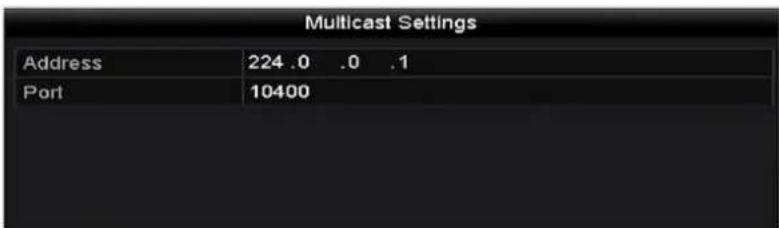
Figure 9-10 Mulcast Sengs
- Sni Connecon
Connect the DVR and the POS machine via Sni. Congure the source address and desnaon address sengs.

Figure 9-11 Sni Sengs
Step 7 Set other parameters of characters overly.
4) Select the character encoding format from the drop-down list.
5) Select the overlay mode of the characters to display in scrolling or page mode.
6) Select the font size to small, medium or large.
7) Set the overlay me of the characters. The value ranges from 5 to 3600 sec.
8) Set the delay me of the characters. The value ranges from 5 to 3600 sec.
9) (Oponal) Check the checkbox to enable the POS Overlay in Live View.
10) Select the font color for the characters.

Figure 9-12 Overlay Character Sengs

You can adjust the size and position of textbox on the live view screen of POS sengs interface by dragging the frame.
Step 8 Click Apply to acvate the setngs.
Step 9 (Oponal) You can click the Copy buon to copy the current sengs to other POS (s).

Figure 9-13 Copy POS Sengs
9.2 Configuring Overlay Channel
Purpose
You can assign the POS machine to corresponding channel on which you want to overlay.
Step 1 Enter the Overlay Channel interface.
Menu > Conguraon > POS > Overlay Channel
Step 2 Click to select an analog or IP camera from the camera list on the right, and then click a POS item from the POS list you want to overlay on the selected camera.
Click for to go to the previous or next page of cameras.

Figure 9-14 Overlay Channel Sengs
Step 3 You can also click 📄 to overlay all POS items to the rst 8 channels in order. And the is used to clear all POS overlay sengs.
Step 4 Click the Apply buon to save the sengs.
9.3 Configuring POS Alarm
Purpose
Set the POS alarm parameters to trigger certain channels to start recording, or trigger full screen monitoring, audio warning, nofying the surveillance center, sending email and so on.
Step 1 Enter the POS Sengs interface.
Menu > Conguraon > POS > POS Sengs
Step 2 Follow the steps in Chapter 9.1-9.2 to congregate the POS sengs.
Step 3 Click ▼ enter the alarm sengs interface.

Figure 9-15 Set Trigger Cameras of POS
Step 4 Click Trigger Channel tab and select one or more channels to record or become full-screen monitoring when POS alarm is triggered.
Step 5 Set arming schedule of the channel.
Select Arming Schedule tab to set the channel's arming schedule.
Choose one day of a week and up to eight me periods can be set within each day. Or you can click the Copy buon to copy the me period sengs to other day(s).

Time periods shall not be repeated or overlapped.

Figure 9-16 Set Arming Schedule
Step 6 Click the Handling tab to set up alarm response acons of POS alarm (Refer to Chapter 8.7 Seng Alarm Response Acons).
Repeat the above steps to set up arming schedule of other days of a week.
Click the OK buon to complete the POS sengs of the channel.
Step 7 Select PTZ Linking tab and set PTZ linkage of the POS alarm.
Set PTZ linking parameters and click the OK buon to complete the sengs of the alarm input.

Please check whether the PTZ or speed dome supports PTZ linkage.
![Settings Trigger Channel Arming Schedule Handling PTZ Linking PTZ Linking [A1] Camera 01 Call Preset Preset 1 Call Patrol Patrol 1 Call Pattern Pattern 1 Apply OK Cancel](/content/2026/05/1005813/images/739ff0c7b6ff237c2c6032ce0d231fa692d34f5f5d6692dbccfe6836800f470e.jpg)
Figure 9-17 Set PTZ Linking
Step 8 Click OK to save the sengs.
Chapter 10 VCA Alarm
Purpose
The DVR can receive the VCA alarm (line crossing detecon, intrusion detecon, sudden scene change detecon and audio excepon detecon) sent by analog camera, and the VCA detecon must be enabled and congured on the camera sengs interface rst. All other VCA detecon features must be supported by the connected IP camera.
i NOTE
● The DS-7100 series DVR do not support the VCA alarm.
- DS-7200/7300/8100/9000HUHI-F/N series DVR support VCA (line crossing detecon and intrusion detecon) of all channels. DS-7600HUHI-F/N series DVR support 2-ch VCA (line crossing detecon and intrusion detecon). Channels with audio support audio exceedon detecon.
- HQHI series DVR excluding 7100 series support 2-ch VCA (line crossing detecon and intrusion detecon). Channels with audio support audio excepon detecon.
- Other models support 1-ch VCA (line crossing detecon and intrusion detecon). Channels with audio support audio excepon detecon.
- For the analog channels, the line crossing detecon and intrusion detecon conict with other VCA detecon such as sudden scene change detecon, face detecon and vehicle detecon and heat map or people counting funcons. You can only enable one funcon.
10.1 Face Detection
Purpose
Face detecon funcon detects the face appears in the surveillance scene, and some certain acons can be taken when the alarm is triggered.
Step 1 Enter the VCA sengs interface.
Menu > Camera > VCA
Step 2 Select the camera to congregate the VCA.
You can click the checkbox of Save VCA Picture to save the captured pictures of VCA detecon.
![VCA Camera [D2] Camera 01 Save VCA PI... Face Def... Vehicle ... Line Cro... Intrusion ... Region ... Region ... Littering ... People G... Past Mo... Parking ... Unattend... Object R... Audio Ex... Defocus ... Sudden ... PIR Alarm Enable Settings Rule 1 Rule Settings 12-16-2014 Tue 35 2:00 Draw Line Draw Qua ... Clear All Apply Back](/content/2026/05/1005813/images/b5b00b707e70888369a89a1731f4ca84524ae482a18c6d3178100632810cac21.jpg)
Figure 10-1 Face Detecon
Step 3 Select the VCA detecon type to Face Detecon.
Step 4 Click ▶ enter the face detecon sengs interface. Congure the trigger channel, arming schedule and linkage acon for the face detecon alarm. Please refer to step3 to step5 of Chapter 8.1 Setng Moon Detecon for detailed instrucons.
Step 5 Click the Rule Sengs buon to set the face detecon rules. You can drag the slider to set the detecon sensitivity.
Sensitivity: Range [1-5]. The higher the value is, the more easily the face can be detected.

Figure 10-2 Set Face Detecon Sensitivity
Step 6 Click Apply to acvate the sengs.
10.2 Vehicle Detection
Purpose
Vehicle Detecon is available for the road trac monitoring. In Vehicle Detecon, the passed vehicle can be detected and the picture of its license plate can be captured. You can send alarm signal to nofy the surveillance center and upload the captured picture to FTP server.
Step 1 Enter the VCA sengs interface.
Menu> Camera> VCA
Step 2 Select the camera to congregate the VCA.
You can click the checkbox of Save VCA Picture to save the captured pictures of VCA detecon.
Step 3 Select the VCA detecon type to Vehicle Detecon.
Step 4 Check the Enable checkbox to enable this funcon.
![VCA Camera [D2] Camera 01 Face Det... Vehicle ... Line Cro... Intrusion ... Region ... Region ... Loitering ... People G... Fast Mo... Parking ... Unattend... Object R... Audio Ex... Defocus ... Sudden ... PIR Alarm Enable Settings Blacklist Whitelist Others Rule 1 03-26-2015 The 19:19:30 Draw Line Blacklist & Whit... Import/Export Draw Qua... No. Plate No. Type Clear All #0# #1 #1# Camera 01 Apply Back](/content/2026/05/1005813/images/90c7344685c075a8da65853386c51b7bd302be1d985e21f9cb015e098b2d1ab9.jpg)
Figure 10-3 Set Vehicle Detecon
Step 5 Click 🧑 to congregate the trigger channel, arming schedule and linkage acons for the Blacklist, Whitelist and Others.
Step 6 Click the Rule Setngs to enter the rule sengs interface. Congure the lane, upload picture and overlay content sengs. Up to 4 lanes are selectable.

Figure 10-4 Rule Sengs
Step 7 Click Save to save the sengs.
i NOTE
Please refer to the User Manual of Network Camera for the detailed instrucons for the vehicle detecon.
10.3 Line Crossing Detection
Purpose
This funcon can be used for detectng people, vehicles and objects cross a set virtual line. The line crossing direcon can be set as bidireconal, from le to right or from right to le. And you can set the duraon for the alarm response acons, such as full screen monitoring, audible warning, etc.
Step 1 Enter the VCA sengs interface.
Menu> Camera> VCA
Step 2 Select the camera to congregate the VCA.
You can click the checkbox of Save VCA Picture to save the captured pictures of VCA detecon.
Step 3 Select the VCA detecon type to Line Crossing Detecon.
Step 4 Check the Enable checkbox to enable this funcon.
Step 5 Click ☐ to congregate the trigger channel, arming schedule and linkage acons for the line crossing detecon alarm.
Step 6 Click the Rule Sengs buon to set the line crossing detecon rules.
1) Select the direcon to A<->B, A->B or B->A.
A<->B: Only the arrow on the B side shows. When an object goes across the congured line, both direcons can be detected and alarms are triggered.
A->B: Only the object crossing the congured line from the A side to the B side can be detected.
B->A: Only the object crossing the congured line from the B side to the A side can be detected.
2) Drag the slider to set the detecon sensitivity.
Sensitivity: Range [1-100]. The higher the value is, the more easily the detecon alarm can be triggered.
3) Click OK to save the rule sengs and return to the line crossing detecon sengs interface.
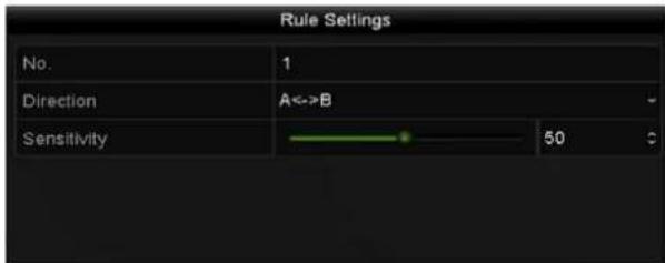
Figure 10-5 Set Line Crossing Detecon Rules
Step 7 Click 📋 and set two points in the preview window to draw a virtual line.
You can use the ⚫ clear the existing virtual line and re-draw it.

Up to 4 rules can be congured.
![VCA Camera [D1] IPdome Save VCA PI... Face Det... Vehicle ... Line Cro... Intrusion ... Region ... Region ... Loitering ... People G... Fast Mo... Parking ... Unattend... Object R... Audio Ex... Defocus ... Sudden ... PIR Alarm Enable Settings Rule 1 Rule Settings 04-03-2015 Fcl 10:50:53 Draw Line Draw Qua... Clear All Apply Back](/content/2026/05/1005813/images/009171ae9b79910de4cb98ff8046a2af3e1e3de49e12d557dd875f3b15eb37e1.jpg)
Figure 10-6 Draw Line for Line Crossing Detecon
Step 8 Click Apply to acvate the sengs.

The sudden scene change detecon and the line crossing detecon cannot be enabled at the same channel.
10.4 Intrusion Detection
Purpose
Intrusion detecon funcon detects people, vehicle or other objects which enter and loiter in a pre-dened virtual region, and some certain acons can be taken when the alarm is triggered.
Step 1 Enter the VCA sengs interface.
Menu> Camera> VCA
Step 2 Select the camera to congregate the VCA.
You can click the checkbox of Save VCA Picture to save the captured pictures of VCA detecon.
Step 3 Select the VCA detecon type to Intrusion Detecon.
Step 4 Check the Enable checkbox to enable this funcon.
Step 5 Click ☐ congregate the trigger channel, arming schedule and linkage acons for the intrusion detecon alarm.
Step 6 Click the Rule Sengs buon to set the intrusion detecon rules. Set the following parameters.
1) Threshold: Range [1s-10s], the threshold for the me of the object loitering in the region. When the duraon of the object in the dened detecon area is longer than the set me, the alarm will be triggered.
2) Drag the slider to set the detecon sensitivity.
Sensitivity: Range [1-100]. The value of the sensitivity denotes the size of the object which can trigger the alarm. The higher the value is, the more easily the detecon alarm can be triggered.
3) Percentage: Range [1-100]. Percentage denotes the rao of the in-region part of the object which can trigger the alarm. For example, if the percentage is set as 50%, when the object enters the region and occupies half of the whole region, the alarm is triggered.
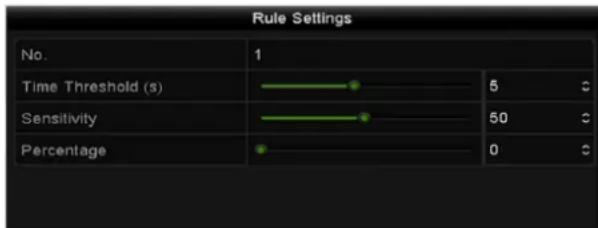
Figure 10-7 Set Intrusion Crossing Detecon Rules
4) Click OK to save the rule sengs and back to the line crossing detecon sengs interface.
Step 7 Click and draw a quadrilateral in the preview window by specifying four vertexes of the detecon region, and right click to complete drawing. Only one region can be congured.
You can use the ☐ clear the exisng virtual line and re-draw it.

Up to 4 rules can be congured.
![VCA Camera [D1] IPdome Save VCA Pi... Face Det... Vehicle ... Line Cro... Intrusion ... Region ... Region ... Loitering... People G... Fast Mo... Parking ... Unattend... Object R... Audio Ex... Defocus ... Sudden ... PIR Alarm Enable ✓ Settings + Rule 1 Rule Settings 01-15-2015 Tue 09:01:14 Draw Line Draw Qua... Clear All Apply Back](/content/2026/05/1005813/images/f331a877898812101f38fbbe8560e64f7ffa6f656f59f0132a38fb072cb28fc2.jpg)
Figure 10-8 Draw Area for Intrusion Detecon
Step 8 Click Apply to save the sengs.

The sudden scene change detecon and the intrusion detecon cannot be enabled at the same channel.
10.5 Region Entrance Detection
Purpose
Region entrance detecon funcon detects people, vehicle or other objects which enter a pre-dened virtual region from the outside place, and some certain acons can be taken when the alarm is triggered.
Step 1 Enter the VCA sengs interface.
Menu> Camera> VCA
Step 2 Select the camera to congregate the VCA.
You can click the checkbox of Save VCA Picture to save the captured pictures of VCA detecon.
Step 3 Select the VCA detecon type to Region Entrance Detecon.
Step 4 Check the Enable checkbox to enable this funcon.
Step 5 Click 🙏 to conjure the trigger channel, arming schedule and linkage acons for the region entrance detecon alarm.
Step 6 Click the Rule Sengs buon to set the sensitivity of the region entrance detecon.
Sensitivity: Range [0-100]. The higher the value is, the more easily the detecon alarm can be triggered.
Step 7 Click 📄d draw a quadrilateral in the preview window by specifying four vertexes of the detecon region, and right click to complete drawing. Only one region can be congured.
You can use the Ⓞ clear the exisng virtual line and re-draw it.
![VCA Camera [D1] IPdome Save VCA Pi... Face Det... Vehicle ... Line Cro... Intrusion ... Region ... Region ... Loitering... People G... Fast Mo... Parking ... Unattend... Object R... Audio Ex... Defocus ... Sudden ... PIR Alarm Enable Settings Rule 1 Rule Settings 01-15-2015 T: 00:04:26 Draw Line Draw Qua... Clear All Apply Back](/content/2026/05/1005813/images/e0276d16128ba9b504e9246e127df3add9f45f80c948c8e47aa640eb3eef6bbb.jpg)
Figure 10-9 Set Region Entrance Detecon

Up to 4 rules can be congured.
Step 8 Click Apply to save the sengs.
10.6 Region Exiting Detection
Purpose
Region exing detecon funcon detects people, vehicle or other objects which exit from a pre-dened virtual region, and some certain acons can be taken when the alarm is triggered.
i NOTE
- Please refer to the Chapter 10.5 Region Entrance Detecon for operang steps to congregate the region exing detecon.
- Up to 4 rules can be congured.
10.7 Loitering Detection
Purpose
Loitering detecon funcon detects people, vehicle or other objects which loiter in a pre-dened virtual region for some certain me, and a series of acons can be taken when the alarm is triggered.
i NOTE
- Please refer to the Chapter 10.4 Intrusion Detecon for operang steps to conjure the loitering detecon.
- The Threshold [1s-10s] in the Rule Sengs denies the me of the object loitering in the region. If you set the value as 5, alarm is triggered aer the object loitering in the region for 5s; and if you set the value as 0, alarm is triggered immediately aer the object entering the region.
- Up to 4 rules can be congured.
10.8 People Gathering Detection
Purpose
People gathering detecon alarm is triggered when people gather around in a pre-dened virtual region, and a series of acons can be taken when the alarm is triggered.
i NOTE
- Please refer to the Chapter 10.4 Intrusion Detecon for operang steps to conjure the people gathering detecon.
- The Percentage in the Rule Sengs denes the gathering density of the people in the region. Usually, when the percentage is small, the alarm can be triggered when small number of people gathered in the dened detecon region.
- Up to 4 rules can be congured.
10.9 Fast Moving Detection
Purpose
Fast moving detecon alarm is triggered when people, vehicle or other objects move fast in a pre-dened virtual region, and a series of acons can be taken when the alarm is triggered.
i NOTE
- Please refer to the Chapter 10.4 Intrusion Detecon for operang steps to conjure the fast moving detecon.
- The Sensitivity in the Rule Sengs denies the moving speed of the object which can trigger the alarm. The higher the value is, the more easily a moving object can trigger the alarm.
- Up to 4 rules can be congured.
10.10 Parking Detection
Purpose
Parking detecon funcon detects illegal parking in places such as highway, one-way street, etc., and a series of acons can be taken when the alarm is triggered.
i NOTE
- Please refer to the Chapter 10.4 Intrusion Detecon for operang steps to conjure the parking detecon.
- The Threshold [5s-20s] in the Rule Sengs denies the me of the vehicle parking in the region. If you set the value as 10, alarm is triggered aer the vehicle stay in the region for 10s.
- Up to 4 rules can be congured.
10.11 Unattended Baggage Detection
Purpose
Unaended baggage detecon funcon detects the objects le over in the pre-dened region such as the baggage, purse, dangerous materials, etc., and a series of acons can be taken when the alarm is triggered.
i NOTE
- Please refer to the Chapter 10.4 Intrusion Detecon for operang steps to conjure the unaended baggage detecon.
- The Threshold [5s-20s] in the Rule Sengs denes the me of the objects le over in the region. If you set the value as 10, alarm is triggered aer the object is le and stay in the region for 10s. And the Sensitivity denes the similarity degree of the background image. Usually, when the sensitivity is high, a very small object le in the region can trigger the alarm.
● Up to 4 rules can be congured.
10.12 Object Removal Detection
Purpose
Object removal detecon funcon detects the objects removed from the pre-dened region, such as the exhibits on display, and a series of acons can be taken when the alarm is triggered.
i NOTE
- Please refer to the Chapter 10.4 Intrusion Detecon for operang steps to conjure the object removal – detecon.
- The Threshold [5s-20s] in the Rule Sengs denes the me of the objects removed from the region. If you set the value as 10, alarm is triggered aer the object disappears from the region for 10s. And the Sensitivity denes the similarity degree of the background image. Usually, when the sensitivity is high, a very small object taken from the region can trigger the alarm.
● Up to 4 rules can be congured.
10.13 Audio Exception Detection
Purpose
Audio excepon detecon funcon detects the abnormal sounds in the surveillance scene, such as the sudden increase/decrease of the sound intensity, and some certain acons can be taken when the alarm is triggered.
i NOTE
The audio excepon detecon is supported by all analog channels.
Step 1 Enter the VCA sengs interface.
Menu> Camera> VCA
Step 2 Select the camera to congregate the VCA.
You can click the checkbox of Save VCA Picture to save the captured pictures of VCA detecon.
Step 3 Select the VCA detecon type to Audio Excepon Detecon.
Step 4 Click 🙏 to congregate the trigger channel, arming schedule and linkage acon for the audio excepon alarm.
Step 5 Click the Rule Sengs buon to set the audio excepon rules.
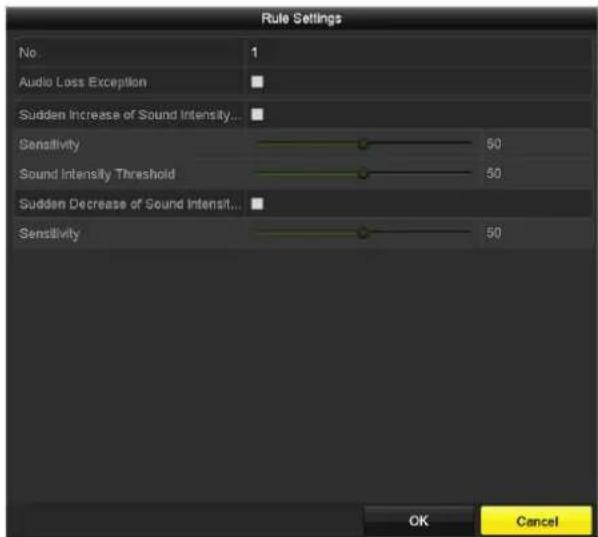
Figure 10-10 Set Audio Excepon Detecon Rules
1) Check the checkbox of Audio Loss Excepon to enable the audio loss detecon funcon.
2) Check the checkbox of Sudden Increase of Sound Intensity Detecon to detect the sound steep rise in the surveillance scene. You can set the detecon sensitivity and threshold for sound steep rise.
Sensitivity: Range [1-100], the smaller the value is, the more severe the change should be to trigger the detecon.
Sound Intensity Threshold: Range [1-100], it can iter the sound in the environment, the louder the environment sound, the higher the value should be. You can adjust it according to the real environment.
3) Check the checkbox of Sudden Decrease of Sound Intensity Detecon to detect the sound steep drop in the surveillance scene. You can set the detecon sensitivity [1-100] for sound steep drop.
Step 6 Click Apply to acvate the sengs.
10.14 Defocus Detection
Purpose
The image blur caused by defocus of the lens can be detected, and some certain acons can be taken when the alarm is triggered.
i NOTE
- Please refer to the Chapter 10.1 Face Detecon for operang steps to conjure the defocus detecon.
- The Sensitivity in the Rule Sengs ranges from 1 to 100, and the higher the value is, the more easily the defocus image can trigger the alarm.
10.15 Sudden Scene Change
Purpose
Scene change detecon funcon detects the change of surveillance environment aected by the external factors; such as the intestinal rotaon of the camera and some certain acons can be taken when the alarm is triggered.
i NOTE
- Please refer to the Chapter 10.1 Face Detecon for operang steps to congure the scene change detecon.
- The Sensitivity in the Rule Sengs ranges from 1 to 100, and the higher the value is, the more easily the change of scene can trigger the alarm.
- For the analog cameras, the line crossing detecon and intrusion detecon conict with other VCA detecon such as sudden scene change detecon, face detecon and vehicle detecon. You can only enable one funcon. If you have enabled line crossing detecon or intrusion detecon, when you enable sudden scene change detecon and apply the sengs, the following aenon box pops up to remind you there is no enough resource and ask you to disable the enabled VCA type(s) of the selected channel(s).

Figure 10-11 Disable Other VCA Type(s)
10.16 PIR Alarm
Purpose
A PIR (Passive Infrared) alarm is triggered when an intruder moves within the detector's eld of view. The heat energy dissipated by a person, or any other warm blooded creature such as dogs, cats, etc., can be detected.
Step 1 Enter the VCA sengs interface.
Menu> Camera> VCA
Step 2 Select the camera to conjure the VCA.
You can click the checkbox of Save VCA Picture to save the captured pictures of VCA detecon.
Step 3 Select the VCA detecon type to PIR Alarm.
Step 4 Click ☐ to configure the trigger channel, arming schedule and linkage acon for the PIR alarm.
Step 5 Click the Rule Sengs buon to set the rules. Please refer to the Chapter 10.1 Face Detecon for instrucons.
Step 6 Click Apply to acvate the sengs.
Chapter 11 VCA Search
With the congured VCA detecon, the device supports the VCA search for the behavior search, face search, plate search, people counting and heat map results.

The DS-7100 series DVR do not support the VCA search.
11.1 Face Search
Purpose
When there are detected face picture captured and saved in HDD, you can enter the Face Search interface to search the picture and play the picture related video les according to the specied condions.
Before you start
Please refer to Secon 10.1 Face Detecon for conguring the face detecon.
Step 1 Enter the Face Search interface.
Menu>VCA Search> Face Search
Step 2 Select the camera (s) for the face search.

Figure 11-1 Face Search
Step 3 Specify the start me and end me for searching the captured face pictures or video les.
Step 4 Upload the pictures from your local storage device for matching the detected face pictures.
Step 5 Set the similarity level for the source pictures and the captured pictures.
Step 6 Click Search to start searching. The search results of face detecon pictures are displayed in list or in chart.

Figure 11-2 Face Search Interface
Step 7 Play the face picture related video le.
You can double click on a face picture to play its related video le in the view window on the top right, or select a picture item and click 📄 to play it.
You can also click stop the playing, or click / to play the previous/next le.
Step 8 If you want to export the captured face pictures to local storage device, connect the storage device to the device and click Export All to enter the Export interface.
Click Export to export all face pictures to the storage device.
Please refer to Chapter 7 Backup for the operaon of exporng les.
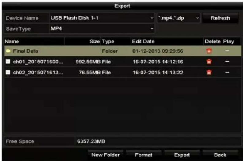
Figure 11-3 Export Files
11.2 Behavior Search
Purpose
The behavior analysis detects a series of suspicious behavior based on VCA detecon, and certain linkage methods will be enabled if the alarm is triggered.
Step 1 Enter the Behavior Search interface.
Menu>VCA Search> Behavior Search
Step 2 Select the camera (s) for the behavior search.
Step 3 Specify the start me and end me for searching the matched pictures.

Figure 11-4 Behavior Search Interface
Step 4 Select the VCA detecon type from the dropdown list, including the line crossing detecon, intrusion detecon, unaended baggage detecon, object removal detecon, region entrance detecon, region exing detecon, parking detecon, loitering detecon, people gathering detecon and fast moving detecon.
Step 5 Click Search to start searching. The search results of pictures are displayed in list or in chart.
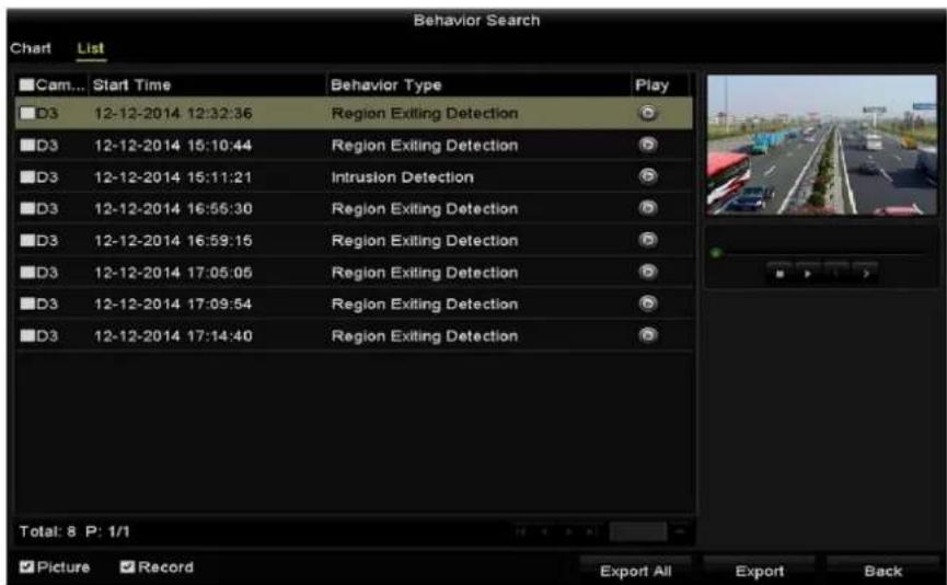
Figure 11-5 Behavior Search Results
Step 6 Play the behavior analysis picture related video le.
You can double click on a picture from the list to play its related video le in the view window on the top right, or select a picture item and click 📐 to play it.
You can also click □ stop the playing, or click / □ play the previous/next le.
Step 7 If you want to export the captured pictures to local storage device, connect the storage device to the device and click Export All to enter the Export interface.
Click Export to export all pictures to the storage device.
11.3 Plate Search
Purpose
You can search and view the matched captured vehicle plate picture and related informaon according to the plate searching conditions including the start me/end me, country and plate No.
Step 1 Enter the Plate Search interface.
Menu>VCA Search> Plate Search
Step 2 Select the camera (s) for the plate search.
Step 3 Specify the start me and end me for searching the matched plate pictures.

Figure 11-6 Plate Search
Step 4 Select the country from the drop-down list for searching the locaon of the vehicle plate.
Step 5 Input the plate No. in the eld for search.
Step 6 Click Search to start searching. The search results of detected vehicle plate pictures are displayed in list or in chart.

Please refer to the Step 7 to Step 8 of Secon 11.1 Face Search for the operaon of the search results.
11.4 People Counting
Purpose
The People Counng is used to calculate the number of people entered or le a certain congured area and form in daily/weekly/monthly/annual reports for analysis.

For DS-7300/8100/9000HUHI-F/N series DVR, people counng is applicable to 1-ch analog camera. The people counng funcon conicts with line crossing detecon, intrusion detecon, sudden scene change detecon, face detecon, vehicle detecon and heat map. You can only enable one funcon for the analog camera.
Step 1 Enter the People Counng interface.
Menu>VCA Search> People Counng
Step 2 Select the camera for the people counng.
Step 3 Select the report type to Daily Report, Weekly Report, Monthly Report or Annual Report.
Step 4 Set the stascs me.
Step 5 Click the Counng buon to start people counng stascs.

line
| Hour | People Entered | People Exited | |------|----------------|---------------| | 1 | 0 | 0 | | 2 | 0 | 0 | | 3 | 0 | 0 | | 4 | 0 | 0 | | 5 | 0 | 0 | | 6 | 0 | 0 | | 7 | 0 | 0 | | 8 | 0 | 0 | | 9 | 0 | 0 | | 10 | 0 | 0 | | 11 | 0 | 0 | | 12 | 0 | 0 | | 13 | 0 | 0 | | 14 | 0 | 0 | | 15 | 0 | 0 | | 16 | 1 | 0 | | 17 | 3 | 0 | | 18 | 9 | 0 | | 19 | 3 | 0 | | 20 | 0 | 0 | | 21 | 0 | 0 | | Back | | |Figure 11-7 People Counng Interface
Step 6 You can click the Export buon to export the stascs report in excel format.
11.5 Heat Map
Purpose
Heat map is a graphical representaon of data represented by colors. The heat map funcon is usually used to analyze the visit mes and dwell me of customers in a congured area.

For DS-7300/8100/9000HUHI-F/N series DVR, heat map is applicable to 1-ch analog camera. The heat map funcon conicts with line crossing detecon, intrusion detecon, sudden scene change detecon, face detecon, vehicle detecon and people counng. You can only enable one funcon for the analog camera.
Step 1 Enter the Heat Map interface.
Menu>VCA Search> Heat Map
Step 2 Select the camera for the heat map processing.
Step 3 Select the report type to Daily Report, Weekly Report, Monthly Report or Annual Report.
Step 4 Set the stascs me.
![Heat Map Camera [A1] Camera 01 Report Type Daily Report Statistics Time 09-12-2016 Counting Export Deck](/content/2026/05/1005813/images/6c1e98d3079071437e4428b7d40c420fb584441edc33d5588affebfad6a3bf42.jpg)
Figure 11-8 Heat Map Interface
Step 5 Click the Counng buon to export the report data and start heat map stascs, and the results are displayed in graphics marked in dierent colors.

As shown in Figure 10-8, red color block (255, 0, 0) indicates the most welcome area, and blue color block (0, 0, 255) indicates the less-popular area.
Step 6 You can click the Export buon to export the stascs report in excel format.
Chapter 12 Network Settings
12.1 Configuring General Settings
Purpose
Network sengs must be properly congured before you operate DVR over network.
Step 1 Enter the Network Sengs interface.
Menu > Conguraon > Network

Figure 12-1 Network Sengs Interface (1)

2 self-adapve 10M/100M/1000M network interfaces for DS-8100HQHI-F/N and DS-7300/8100/9000HUHI-F/N series. For DS-8100HQHI-F/N series, three working modes are congorable: mul-address, load balance, network fault tolerance. For DS-7300/8100/9000HUHI-F/N series, only mul-address and network fault tolerance are congorable. 1 self-adapve 10M/100M/1000M network interface or 1 self-adapve 10M/100Mbps network interface provided for other models.
Step 2 Select the General tab.
Step 3 In the General Sengs interface, you can congregate the following parameters: Working Mode (applicable for DS-8100HQHI-F/N and DS-7300/8100/9000HUHI-F/N series), NIC Type, IPv4 Address, IPv4 Gateway, MTU, DNS Server and Main NIC.
Working Mode
There are two 10M/100M/1000M NIC cards provided by the DS-8100HQHI-F/N and DS-7300/8100/9000HUHI-F/N series devices, and it allows the device to work in the Mul-address, Load Balance and Net-fault Tolerance modes for DS-8100HQHI-F/N and Mul-address and Net-fault Tolerance for DS-7300/8100/9000HUHI-F/N.
- Mul-address Mode: The parameters of the two NIC cards can be congured independently. You can select LAN1 or LAN2 in the NIC type eld for parameter sengs.
You can select one NIC card as default route. And then the system is connecng with the extranet and the data will be forwarded through the default route. - Net-fault Tolerance Mode: The two NIC cards use the same IP address, and you can select the Main NIC to LAN1 or LAN2. By this way, in case of one NIC card failure, the device will automatically enable the other standby NIC card so as to ensure the normal running of the whole system.
- Load Balance Mode: By using the same IP address and two NIC cards share the load of the total bandwidth, which enables the system to provide two Gigabit network capacity.
i NOTE
● The valid value of MTU is from 500 to 1500.
- If the DHCP server is available, you can check the checkbox of Enable DHCP to automatically obtain an IP address and other network sengs from that server.
- For -F series DVR, if DHCP is enabled, you can check the checkbox of Enable DNS DHCP or uncheck it and edit the Preferred DNS Server and Alternate DNS Server.
Step 4 Aer having congured the general sengs, click the Apply buon to save the sengs.
12.2 Configuring Advanced Settings
12.2.1 Configuring PPPoE Settings
Purpose
The DVR also allows access by Point-to-Point Protocol over Ethernet (PPPoE).
Step 1 Enter the Network Sengs interface.
Menu > Conguraon > Network
Step 2 Select the PPPoE tab to enter the PPPoE Sengs interface.

Figure 12-2 PPPoE Sengs Interface
Step 3 Check the Enable PPPoE checkbox to enable this feature.
Step 4 Enter User Name and Password for PPPoE access.
i NOTE
The User Name and Password should be assigned by your ISP.
Step 5 Click the Apply buon to save the sengs.
Step 6 Aer successful sengs, the system asks you to reboot the device to enable the new sengs, and the PPPoE dial-up is automacally connected aer reboot.
You can go to Menu > Maintenance > System Info > Network interface to view the status of PPPoE conncon.
12.2.2 Configuring Hik Cloud P2P
Purpose
Hik Cloud P2P provides the mobile phone applicaon and as well the service plaorm page to access and manage your connected DVR, which enables you to get a convenient remote access to the surveillance system.
Step 1 Enter the Network Sengs interface.
Menu > Conguraon > Network
Step 2 Select the Plaorm Access tab to enter the Hik Cloud P2P Sengs interface.
Step 3 Check the Enable checkbox to acvate this feature.
Step 4 If required, select the checkbox of Custom and input the Server Address.
Step 5 To turn the Enable Stream Encrypon on, you can select its checkbox.
Step 6 Enter the Vericaon Code of the device.

The vericaon code consists of 6 capital leers and is located at the boom of the DVR. You can also use the scanning tool of your phone to quickly get the code by scanning the QR code below.
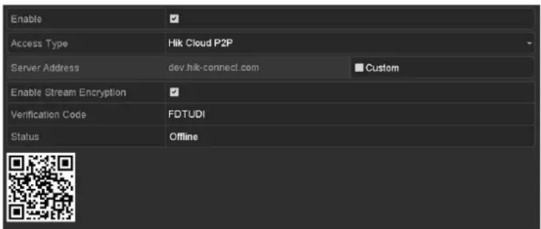
Figure 12-3 Hik Cloud P2P Sengs Interface
Step 7 Click the Apply buon to save and exit the interface.
Aer conguraon, you can access and manage the DVR by your mobile phone on which the Hik Cloud P2P applicaon is installed or by the website (dev.hik-connect.com).

For more operaon instrucons, please refer to the help le on the ocial website (dev.hik-connect.com).
12.2.3 Configuring DDNS
Purpose
If your DVR is set to use PPPoE as its default network conncon, you may set Dynamic DNS (DDNS) to be used for network access.
Prior registraon with your ISP is required before conguring the system to use DDNS.
Step 1 Enter the Network Sengs interface.
Menu > Conguraon > Network
Step 2 Select the DDNS tab to enter the DDNS Sengs interface.
Step 3 Check the Enable DDNS checkbox to enable this feature.
Step 4 Select DDNS Type. Five dierent DDNS types are selectable: IPServer, DynDNS, PeanutHull, NO-IP and HiDDNS.
- IPServer: Input Server Address for IPServer.

Figure 12-4 IPServer Sengs Interface
- DynDNS:
1) Enter Server Address for DynDNS (i.e. members.dyndns.org).
2) In the Device Domain Name text eld, enter the domain obtained from the DynDNS website.
3) Enter the User Name and Password registered in the DynDNS website.

Figure 12-5 DynDNS Sengs Interface
- PeanutHull: Enter the User Name and Password obtained from the PeanutHull website.

Figure 12-6 PeanutHull Sengs Interface
NO-IP:
Enter the account informaon in the corresponding elds. Refer to the DynDNS sengs.
1) Enter Server Address for NO-IP.
2) In the Device Domain Name text eld, enter the domain obtained from the NO-IP website (www.no-ip.com).
3) Enter the User Name and Password registered in the NO-IP website.

Figure 12-7 NO-IP Sengs Interface
- HiDDNS:
1) The Server Address of the HiDDNS server appears by default: www.hik-online.com.
2) Select your Area/Country in the dropdown list.
3) Enter the Device Domain Name. You can use the alias you registered in the HiDDNS server or dene a new device domain name. If a new alias of the device domain name is dened in the DVR, it will replace the old one registered on the server. You can register the alias of the device domain name in the HiDDNS server rst and then enter the alias to the Device Domain Name in the DVR. You can also enter the domain name directly on the DVR to create a new one.

Figure 12-8 HiDDNS Sengs Interface
Register the device on the HiDDNS server.
1) Go to the HiDDNS website: www.hik-online.com.
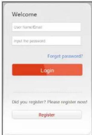
Figure 12-9 Login Interface
2) Click Register to register an account if you do not have one and use the account to log in.

Figure 12-10 Register an Account
3) In the Device Management interface, click Add to register the device.
![Add Device • Device Serial No.: • Device Domain: Only numeric, lower case letters and _ are supported, and the string cannot be ended with '.' or space, The length range [1-64] • HTTP Port: 0 Normally please do not change the default port value '0', unless NAT function is enabled on the router and the external http port is of different value from the internal. In that case please input the value of external port here. OK Cancel](/content/2026/05/1005813/images/8dd4b455b0df89261c7a5610f4c996c12bfbfcdb7cc4d614de48e18e04ec8a23.jpg)
Figure 12-11 Register the Device
4) Input Device Serial No., Device Domain (Device Name) and HTTP Port. And click OK to add the device.
Access the Device via Web Browser or Client Soware
Aer having successfully registered the device on the HiDDNS server, you can access your device via web browser or Client Soware with the Device Domain (Device Name).
- OPTION 1: Access the Device via Web Browser
Open a web browser, and enter hp://www.hik-online.com/alias in the address bar. Alias refers to the Device Domain on the device or the Device Name on the HiDDNS server.
Example: hp://www.hik-online.com/nvr

If you mapped the HTTP port on your router and changed it to port No. except 80, you have to enter hp://www.hik-online.com/alias:HTTP port in the address bar to access the device. You can refer to Chapter 12.2.7 Conguring HTTPS Port for the mapped HTTP port No..
● OPTION 2: Access the devices via iVMS-4200
For iVMS-4200, in the Add Device window, select and then edit the device informaon.
Nickname: Edit a name for the device as you want.
Server Address: www.hik-online.com
Device Domain Name: It refers to the Device Domain Name on the device or the Device Name on the HiDDNS server you created.
User Name: Enter the user name of the device.
Password: Enter the password of the device.
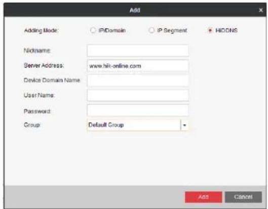
Figure 12-12 Access Device via iVMS-4200
Step 5 Click the Apply buon to save and exit the interface.
12.2.4 Configuring NTP Server
Purpose
A Network Time Protocol (NTP) Server can be congured on your DVR to ensure the accuracy of system date/me.
Step 1 Enter the Network Sengs interface.
Menu > Conguraon > Network
Step 2 Select the NTP tab to enter the NTP Sengs interface.
| Enable NTP | ✓ |
| Interval (min) | 60 |
| NTP Server | 210.72.145.44 |
| NTP Port | 123 |
Figure 12-13 NTP Sengs Interface
Step 3 Check the Enable NTP checkbox to enable this feature.
Step 4 Congure the following NTP sengs:
- Interval: Time interval between the two synchronizing acons with NTP server. The unit is minute.
● NTP Server: IP address of NTP server.
● NTP Port: Port of NTP server.
Step 5 Click the Apply buon to save and exit the interface.
i NOTE
The me synchronizaon interval can be set from 1 to 10080 minutes, and the default value is 60 minutes. If the DVR is connected to a public network, you should use a NTP server that has a me synchronizaon funcon, such as the server at the Naonal Time Center (IP Address:
210.72.145.44). If the DVR is set in a more customized network, NTP soware can be used to establish a NTP server used for me synchronizaon.
12.2.5 Configuring NAT
Purpose
Universal Plug and Play (UPnP™) can permit the device seamlessly discover the presence of other network devices on the network and establish functional network services for data sharing, communicaons, etc. You can use the UPnP™ funcon to enable the fast conneccon of the device to the WAN via a router without port mapping.
Before you start
If you want to enable the UPnP™ funcon of the device, you must enable the UPnP™ funcon of the router to which your device is connected. When the network working mode of the device is set as mul-address, the Default Route of the device should be in the same network segment as that of the LAN IP address of the router.
Step 1 Enter the Network Sengs interface.
Menu > Conguraon > Network
Step 2 Select the NAT tab to enter the UPnP™ Sengs interface.

Figure 12-14 UPnP™ Sengs Interface
Step 3 Check Enable UPnP checkbox to enable UPnP™.
Step 4 Select the Mapping Type as Manual or Auto in the drop-down list.
OPTION 1: Auto
If you select Auto, the Port Mapping items are read-only, and the external ports are set by the router automacally.
1) Click Apply buon to save the sengs.
2) You can click Refresh buon to get the latest status of the port mapping.

Figure 12-15 UPnP™ Sengs Finished-Auto
OPTION 2: Manual
If you select Manual as the mapping type, you can edit the external port on your demand by clicking ☐ to acvate the External Port Sengs dialog box.
1) Click ☑ to acvate the External Port Sengs dialog box. Congure the external port No. for server port, hp port and RTSP port respectively.
i NOTE
- You can use the default port No., or change it according to actual requirements.
● External Port indicates the port No. for port mapping in the router. - The value of the RTSP port No. should be 554 or between 1024 and 65535, while the value of the other ports should be between 1 and 65535 and the value must be dierent from each other. If mulple devices are congured for the UPnP™ sengs under the same router, the value of the port No. for each device should be unique.

Figure 12-16 External Port Sengs Dialog Box
2) Click Apply buon to save the sengs.
3) You can click Refresh buon to get the latest status of the port mapping.

Figure 12-17 UPnP™ Sengs Finished-Manual
12.2.6 Configuring More Settings
Step 1 Enter the Network Sengs interface.
Menu > Conguraon > Network
Step 2 Select the More Sengs tab to enter the More Sengs interface.
| Alarm Host IP | |
| Alarm Host Port | 0 |
| Server Port | 8000 |
| HTTP Port | 80 |
| Multicast IP | |
| RTSP Port | 554 |
| Output Bandwidth Limit | ✓ |
| Output Bandwidth (Mbps) | 2 |
Figure 12-18 More Sengs Interface
Step 3 Congure the remote alarm host, server port, HTTP port, mulcast, and RTSP port.
- Alarm Host IP/Port: With a remote alarm host congured, the device will send the alarm event or exception message to the host when an alarm is triggered. The remote alarm host must have the CMS (Client Management System) sow are installed.
The Alarm Host IP refers to the IP address of the remote PC on which the CMS (Client Management System) soware (e.g., iVMS-4200) is installed, and the Alarm Host Port must be the same as the alarm monitoring port congured in the soware (default port is 7200).
- Mulcast IP: The mulcast can be congured to realize live view for more than the maximum number of cameras through network. A mulcast address spans the Class-D IP range of 224.0.0.0 to 239.255.255.255. It is recommended to use the IP address ranging from 239.252.0.0 to 239.255.255.255.
When adding a device to the CMS (Client Management System) soware, the mulcast address must be the same as the device's mulcast IP.
- RTSP Port: The RTSP (Real Time Streaming Protocol) is a network control protocol designed for use in entertainment and communications systems to control streaming media servers.
Enter the RTSP port in the text eld of RTSP Port. The default RTSP port is 554, and you can change it according to dierent requirements.
- Server Port and HTTP Port: Enter the Server Port and HTTP Port in the text elds. The default Server Port is 8000 and the HTTP Port is 80, and you can change them according to dierent requirements.
i NOTE
The Server Port should be set to the range of 2000-65535 and it is used for remote client soware access. The HTTP port is used for remote IE access.
- Output Bandwidth Limit: You can check the checkbox to enable output bandwidth limit.
- Output Bandwidth: Aer enable the output bandwidth limit, input the output bandwidth in the text eld.
i NOTE
- Enabling output bandwidth limit and sengs output bandwidth opons are applicable for -F series DVR.
● The output bandwidth limit is used for the remote live view and playback.
● The minimum output bandwidth is 2 Mbps.
Step 4 Click the Apply buon to save and exit the interface.
12.2.7 Configuring HTTPS Port
Purpose
HTTPS provides authencaon of the web site and associated web server that one is communicang with, which protects against Man-in-the-middle aacks. Perform the following steps to set the port number of hps.
Example
If you set the port number as 443 and the IP address is 192.0.0.64, you may access the device by inpung hps://192.0.0.64:443 via the web browser.

The HTTPS port can be only congured through the web browser.
Step 1 Open web browser, input the IP address of device, and the web server will select the language automacally according to the system language and maximize the web browser.
Step 2 Input the correct user name and password, and click Login buon to log in the device.
Step 3 Enter the HTTPS sengs interface.
Conguraon > Remote Conguraon > Network Sengs > HTTPS
Step 4 Create the self-signed cercate or authorized cercate.

Figure 12-19 HTTPS Sengs
OPTION 1: Create the self-signed cercate
1) Click the Create buon to create the following dialog box.

Figure 12-20 Create Self-signed Cercate
2) Enter the country, host name/IP, validity and other informaon.
3) Click OK to save the sengs.
OPTION 2: Create the authorized cercate
1) Click the Create buon to create the cercate request.
2) Download the cercate request and submit it to the trusted cercate authority for signature.
3) Aer receiving the signed valid cercate, import the cercate to the device.
Step 5 There will be the cercate informaon aer you successfully create and install the cercate.

Figure 12-21 Installed Cercate Property
Step 6 Check the checkbox to enable the HTTPS funcon.
Step 7 Click the Save buon to save the sengs.
12.2.8 Configuring Email
Purpose
The system can be congured to send an Email nocaoon to all designated users if an event is detected, e.g. an alarm or moon event is detected, etc.
Before conguring the Email sengs, the DVR must be connected to a local area network (LAN) that maintains an SMTP mail server. The network must also be connected to either an intranet or the Internet depending on the locaon of the e-mail accounts to which you want to send nocaaon. Additional, the Preferred DNS server must be congured.
Before you start
Make sure you have congured the IPv4 Address, IPv4 Subnet Mask, IPv4 Gateway and the Preferred DNS Server in the Network Sengs menu. Please refer to Chapter 12.1 Conguring General Sengs for detailed informaon.
Step 1 Enter the Network Sengs interface.
Menu > Conguraon > Network
Step 2 Select the Email tab to enter the Email Sengs interface.

Figure 12-22 Email Sengs Interface
Step 3 Congure the following Email sengs:
Enable Server Authencaon (oponal): Check the checkbox to enable the server authencaon feature.
User Name: The user account of sender's Email for SMTP server authencaon.
Password: The password of sender's Email for SMTP server authencaon.
SMTP Server: The SMTP Server IP address or host name (e.g., smtp.263xmail.com).
SMTP Port: The SMTP port. The default TCP/IP port used for SMTP is 25.
Enable SSL (oponal): Click the checkbox to enable SSL if required by the SMTP server.
Sender: The name of sender.
Sender's Address: The Email address of sender.
Select Receivers: Select the receiver. Up to 3 receivers can be congured.
Receiver: The name of the receiver of the Email.
Receiver's Address: The Email address of the receiver.
Enable Aached Picture: Check the checkbox if you want to send email with aached alarm images. The interval is the me between two captures of the alarm images.
i NOTE
- For the IP cameras, the alarm images are directly sent as the aached pictures by Email. Up to one picture can be sent for one IP camera. The aached pictures of the linked cameras cannot be sent.
- For analog cameras, 3 aached pictures can be sent for one analog camera when the alarm is triggered.
Interval: The interval refers to the me between two acons of sending aached pictures.
E-mail Test: Sends a test message to verify that the SMTP server can be reached.
Step 4 Click the Apply buon to save the Email sengs.
Step 5 You can click the Test buon to test whether your Email sengs work. The corresponding Aenon message box pops up.


Figure 12-23 Email Tesng Aenon
12.2.9 Checking Network Traffic
Purpose
You can check the network trac to obtain real-me informaon of DVR such as linking status, MTU, sending/receiving rate, etc.
Step 1 Enter the Network Trac interface.
Menu > Maintenance > Net Detect

line
| Metric | Value | | ------------ | --------- | | Sending | 465Kbps | | Receiving | 28Kbps |Figure 12-24 Network Trac Interface
Step 2 You can view the sending rate and receiving rate informaon on the interface. The trace data is refreshed every 1 second.
12.3 Configuring Network Detection
Purpose
You can obtain network connecng status of DVR through the network detecon funcon, including network delay, packet loss, etc.
12.3.1 Testing Network Delay and Packet Loss
Step 1 Enter the Network Trac interface.
Menu > Maintenance > Net Detect
Step 2 Click the Network Detecon tab to enter the Network Detecon interface.

Figure 12-25 Network Detecon Interface
Step 3 Select a NIC to test network delay and packet loss.
Step 4 Enter the desnaon address in the text eld of Desnaon Address.
Step 5 Click the Test buon to start tesng network delay and packet loss.
12.3.2 Exporting Network Packet
Purpose
By connecng the DVR to network, the captured network data packet can be exported to USB-ash disk, SATA and other local backup devices.
Step 1 Enter the Network Trac interface.
Menu > Maintenance > Net Detect
Step 2 Click the Network Detecon tab to enter the Network Detecon interface.
Step 3 Select the backup device from the dropdown list of Device Name.

Click the Refresh buon if the connected local backup device cannot be displayed. When it fails to detect the backup device, please check whether it is compatible with the DVR. You can format the backup device if the format is incorrect.

Figure 12-26 Export Network Packet
Step 4 Click the Export buon to start exporng.
Step 5 Aer the exporng is complete, click OK to nish the packet export.

Figure 12-27 Packet Export Aenon

Up to 1M data can be exported each me.
12.3.3 Checking Network Status
Purpose
You can also check the network status and quick set the network parameters in this interface.
Step 1 Enter the Network Trac interface.
Menu > Maintenance > Net Detect
Step 2 Click the Network Detecon tab to enter the Network Detecon interface.
Step 3 Click Status on the right bottom of the interface.

Figure 12-28 Checking Network Status
If the network is normal the following message box pops out.

Figure 12-29 Network Status Checking Result
If the message box pops out with other informaon instead of this one, you can click Network buon to show the quick seng interface of the network parameters.
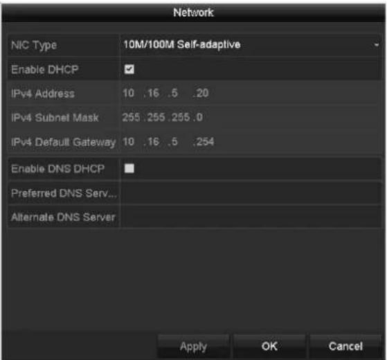
Figure 12-30 Network Parameters Conguraon
12.3.4 Checking Network Statistics
Purpose:
You can check the network stascs to obtain the real-me informaon of the device.
Step 1 Enter the Network Stascs interface.
Menu > Maintenance > Net Detect
Step 2 Click the Network Stat. tab to enter the Network Stascs interface.

Figure 12-31 Network Stat. Interface
Step 3 View the bandwidth of Remote Live View, bandwidth of Remote Playback, and bandwidth of Net Total Idle.
Step 4 Click Refresh buon to get the latest bandwidth stascs.
Chapter 13 RAID

This chapter is applicable for DS-7300/8100/9000HUHI-F/N series DVR.
13.1 Configuring Array
Purpose
RAID (redundant array of independent disks) is a storage technology that combines mulple disk drive components into a logical unit. A RAID setup stores data over mulple hard disk drives to provide enough redundancy so that data can be recovered if one disk fails. Data is distributed across the drives in one of several ways called "RAID levels", depending on what level of redundancy and performance is required.
The DVR supports the disk array that is realized by soware. You can enable the RAID funcon on your demand.

The DS-7300/8100/9000HUHI-F/N series DVR support the RAID0, RAID1, RAID5, RAID6 and RAID 10 array types.
Before you start
Please install the HDD(s) properly and it is recommended to use the same enterprise-level HDDs (including model and capacity) for array creation and configuration so as to maintain reliable and stable running of the disks.
Introducon
The DVR can store the data (such as record, picture, log informaon) in the HDD only aer you have created the array or you have congured network HDD (refer to Chapter14.2 Managing Network HDD). Our device provides two ways for creang array, including one-touch conguraon and manual conguraon. The following ow chart shows the process of creang array.

flowchart
graph TD
    A["Start"] --> B["Enter Disk Mode Interface"]
    B --> C["Enable RAID"]
    C --> D["Enter Physical Disk Interface"]
    D --> E["Manual Creation"]
    D --> F["One-touch Creation"]
    E --> G["Creating Array Finished"]
    G --> H["Array Initialization"]
    F --> I["Creating Array Finished"]
    I --> J["RAID0"]
    J --> K["Enter HDD Information Interface"]
    K --> L["Normal HDD"]
    L --> M["End"]
    style A fill:#99CCFF
    style M fill:#99CCFF
Figure 13-1 RAID Working Flow
13.1.1 Enable RAID
Purpose
Perform the following steps to enable the RAID funcon, or the disk array cannot be created.
- OPTION 1:
Enable the RAID funcon in the Wizard when the device startup, please refer to step 7 of Chapter 2.3.2.
- OPTION 2:
Enable the RAID funcon in the HDD Management Interface.
Step 1 Enter the Disk Mode conguraon interface.
Menu > HDD > Advanced

Figure 13-2 Enable RAID Interface
Step 2 Check the checkbox of Enable RAID.
Step 3 Click the Apply buon to save the sengs.
Step 4 Reboot the device to take RAID into eect.
13.1.2 One-touch Configuration
Purpose
Through one-touch conguraon, you can quickly create the disk array. By default, the array type to be created is RAID 5.
Before you start
- The RAID funcon should be enabled, please refer to the Chapter 13.1.1 for details.
- As the default array type is RAID 5, please install at least 3 HDDs in you device.
- If more than 10 HDDs are installed, 2 arrays can be congured.
Step 1 Enter the RAID conguraon interface.
Menu > HDD > RAID

Figure 13-3 Physical Disk Interface
Step 2 Check the checkbox of corresponding HDD No. to select it.
Step 3 Click the One-touch Config buon to enter the One-touch Array Conguraon interface.

Figure 13-4 One-touch Array Conguraon
Step 4 Edit the array name in the Array Name text led and click OK buon to start conguring array.

If you install 4 HDDs or above for one-touch conguraon, a hot spare disk will be set by default. It is recommended to set hot spare disk for automacally rebuilding the array when the array is abnormal.
Step 5 When the array conguraon is completed, click OK buon in the pop-up message box to nish the sengs.
Step 6 You can click Array tab to view the informaon of the successfully created array.

By default, one-touch conguraon creates an array and a virtual disk.
| Physical Disk Array Firmware | |||||||||
| No. | Name | Free Space | Physic... | Hot ... | Status | Level | Re... | Del... | Task |
| 1 | array1_1 | 931/931G | 2 6 7 | Functi... | RAID 5 | Initialize (Fast)(R) | |||
Figure 13-5 Array Sengs Interface
Step 7 A created array displays as an HDD in the HDD informaon interface.

Figure 13-6 HDD Informaon Interface
13.1.3 Manually Creating Array
Purpose
You can manually create the array of RAID 0, RAID 1, RAID 5, RAID6 and RAID 10.

In this secon, we take RAID 5 as an example to describe the manual conguraon of array and virtual disk.
Step 1 Enter the Physical Disk Sengs interface.
Menu > HDD > RAID > Physical Disk

Figure 13-7 Physical Disk Sengs Interface
Step 2 Click Creat buon to enter the Create Array interface.
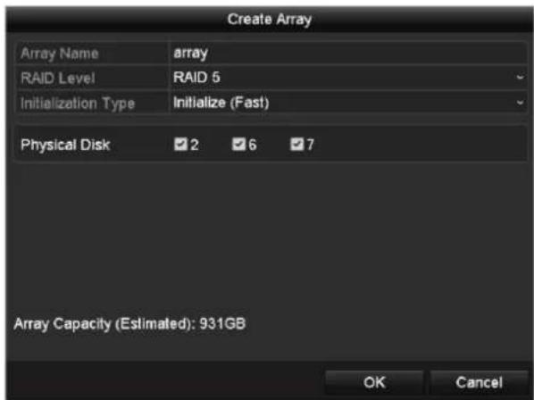
Figure 13-8 Create Array Interface
Step 3 Edit the Array Name; set the RAID Level to RAID 0, RAID 1, RAID 5, RAID6 or RAID 10; select the Physical Disk that you want to congure array.
i NOTE
- If you choose RAID 0, at least 2 HDDs must be installed.
- If you choose RAID 1, 2 HDDs need to be congured for RAID 1.
- If you choose RAID 5, at least 3 HDDs must be installed.
- If you choose RAID 6, at least 4 HDDs must be installed.
- If you choose RAID 10, the number of HDDs installed should be even in the range of 4 to 16
Step 4 Click OK buon to create array.

If the number of HDDs you select is not compatible with the requirement of the RAID level, the error message box will pop up.
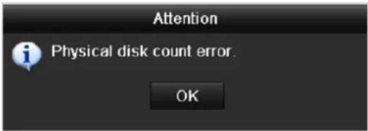
Figure 13-9 Error Message Box
Step 5 You can click Array tab to view the successfully created array.
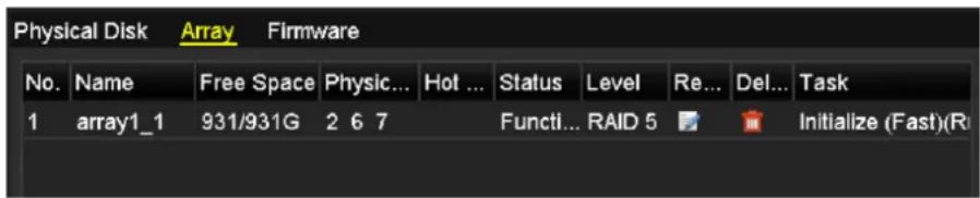
Figure 13-10 Array Sengs Interface
13.2 Rebuilding Array
Purpose
The working status of array includes Funconal, Degraded and Oine. By viewing the array status, you can take immediate and proper maintenance for the disks so as to ensure the high security and reliability of the data stored in the disk array.
When there is no disk loss in the array, the working status of array will change to Funconal; when the number of lost disks has exceeded the limit, the working status of array will change to Oine; in other conditions, the working status is Degraded.
When the virtual disk is in Degraded status, you can restore it to Funconal by array rebuilding.
Before you start
Please make sure the hot spare disk is congured.
Step 1 Enter the Physical Disk Sengs interface to conjure the hot spare disk.

Figure 13-11 Physical Disk Sengs Interface
Step 2 Select a disk and click to set it as the hot spare disk.

Only global hot spare mode is supported.
13.2.1 Automatically Rebuilding Array
Purpose
When the virtual disk is in Degraded status, the device can start rebuilding the array automacally with the hot spare disk to ensure the high security and reliability of the data.
Step 1 Enter the Array Sengs interface. The status of the array is Degraded. Since the hot spare disk is congured, the system will automacally start rebuilding using it.
Menu > HDD > RAID > Array

Figure 13-12 Array Sengs Interface
If there is no hot spare disk aer rebuilding, it is recommended to install a HDD into the device and set is as a hot spare disk to ensure the high security and reliability of the array.
13.2.2 Manually Rebuilding Array
Purpose
If the hot spare disk has not been congured, you can rebuild the array manually to restore the array when the virtual disk is in Degraded status.
Step 1 Enter the Array Sengs interface. The disk 3 is lost.
Menu > HDD > RAID > Array

Figure 13-13 Array Sengs Interface
Step 2 Click Array tab to return to the Array Sengs interface and click rebuild.
to congure the array

At least one available physical disk should exist for rebuilding the array.

Figure 13-14 Rebuild Array Interface
Step 3 Select the available physical disk and click OK buon to conrm to rebuild the array.
Step 4 The “Do not unplug the physical disk when it is under rebuilding” message box pops up. Click OK buon to start rebuilding.
Step 5 You can enter the Array Sengs interface to view the rebuilding status.
Step 6 Aer rebuilding successfully, the array and virtual disk will restore to Funconal.
13.3 Deleting Array

Deleng array will cause to delete all the data saved in the disk.
Step 1 Enter the Array Sengs interface.
Menu>HDD>RAID>Array

Figure 13-15 Array Sengs Interface
Step 2 Select an array and click to delete the array.

Figure 13-16 Conrm Array Deleon
Step 3 In the pop-up message box, click Yes buon to conrm the array deleon.

Deleng array will cause to delete all the data in the array.
13.4 Checking and Editing Firmware
Purpose
You can view the informaon of the rmware and set the background task speed on the Firmware interface.
Step 1 Enter the Firmware interface to check the informaon of the rmware, including the version, maximum physical disk quantity, maximum array quantity, auto-rebuild status, etc.

Figure 13-17 Firmware Interface
Step 2 You can set the Background Task Speed in the drop-down list.
Step 3 Click the Apply buon to save the sengs.
Chapter 14 HDD Management
14.1 Initializing HDDs
Purpose
A newly installed hard disk drive (HDD) must be initialized before it can be used with your DVR.
Step 1 Enter the HDD Informaon interface.
Menu > HDD > General

Figure 14-1 HDD Informaon Interface
You can view the Total Capacity, Free Space and Remaining Recording Time of the HDD. The algorithm of the Remaining Recording Time is to use average bit rate for the channel enabling smart encoding to raise accuracy.
Step 2 Select HDD to be inialized.
Step 3 Click the Init buon.

Figure 14-2 Conrm Inializaon
Step 4 Select the OK buon to start inializaon.

Figure 14-3 Start Inializaon
Step 5 Aer the HDD has been initialized, the status of the HDD will change from Uninialized to Normal.
| L... | Capacity | Status | Property | Type | Free Space | Gr... | Edit | D... |
| 1 | 931.51GB | Normal | RAW | Local | 927GB | 1 |
Figure 14-4 HDD Status Changes to Normal

Initializing the HDD will erase all data on it.
The HDDs which are free of working for a long me can be enabled to sleep, thus to decrease the power consumption of the device and extend the life of the HDDs.
Click Menu > HDD > Advanced

Figure 14-5 Enable HDD Sleeping
Check the checkbox of Enable HDD Sleeping (by default), and the HDDs which are free of working for a long me will be set to sleep.
Uncheck the checkbox of Enable HDD Sleeping, and the HDDs will be set to work for all me.
14.2 Managing Network HDD
Purpose
You can add the allocated NAS or disk of IP SAN to DVR, and use it as network HDD.
Step 1 Enter the HDD Informaon interface.
Menu > HDD>General

Figure 14-6 HDD Informaon Interface
Step 2 Click the Add buon to enter the Add NetHDD interface, as shown in Figure 14-7.

Figure 14-7 HDD Informaon Interface
Step 3 Add the allocated NetHDD.
Step 4 Select the type to NAS or IP SAN.
Step 5 Congure the NAS or IP SAN sengs.
- Add NAS disk:
1) Enter the NetHDD IP address in the text eld.
2) Click Search to search the available NAS disks.
3) Select the NAS disk from the list shown below.
Or you can just manually enter the directory in the text eld of NetHDD Directory.
4) Click OK to add the congured NAS disk.

Up to 8 NAS disks can be added.

Figure 14-8 Add NAS Disk
- Add IP SAN:
1) Enter the NetHDD IP address in the text eld.
2) Click the Search buon to the available IP SAN disks.
3) Select the IP SAN disk from the list shown below.
4) Click the OK buon to add the selected IP SAN disk.

Up to 8 IP SAN disks can be added.

Figure 14-9 Add IP SAN Disk
5) Aer having successfully added the NAS or IP SAN disk, return to the HDD Informaon menu. The added NetHDD will be displayed in the list.

If the added NetHDD is uninitialized, please select it and click the Init buon for inializaon.

Figure 14-10 Inialize Added NetHDD
14.3 Managing HDD Group
14.3.1 Setting HDD Groups
Purpose
Mulple HDDs can be managed in groups. Video from specied channels can be recorded onto a parcular HDD group through HDD sengs.
Step 1 Enter the Storage Mode interface.
Menu > HDD > Advanced
Step 2 Set the Mode to Group, as shown in Figure 14-11.

Figure 14-11 Storage Mode Interface
Step 3 Click the Apply buon and the following Aenon box will pop up.

Figure 14-12 Aenon for Reboot
Step 4 Click the Yes buon to reboot the device to acvate the changes.
Step 5 Aer reboot of device, enter the HDD Informaon interface.
Menu > HDD > General
Step 6 Select HDD from the list and click the 📋 icon to enter the Local HDD Sengs interface, as shown in Figure 14-13.

Figure 14-13 Local HDD Sengs Interface
Step 7 Select the Group number for the current HDD.

The default group No. for each HDD is 1.
Step 8 Click the OK buon to conrm the sengs.

Figure 14-14 Conrm HDD Group Sengs
Step 9 In the pop-up Aenon box, click the Yes buon to nish the sengs.
14.3.2 Setting HDD Property
Purpose
The HDD property can be set to redundancy, read-only or read/write (R/W). Before seng the HDD property, please set the storage mode to Group (refer to step1-4 of Chapter 14.3.1 Seng HDD Groups).
A HDD can be set to read-only to prevent important recorded les from being overwrien when the HDD becomes full in overwrite recording mode.
When the HDD property is set to redundancy, the video can be recorded both onto the redundancy HDD and the R/W HDD simultaneously so as to ensure high security and reliability of video data.
Step 1 Enter the HDD Informaon interface.
Menu > HDD > General
Step 2 Select HDD from the list and click the 📋 icon to enter the Local HDD Sengs interface, as shown in Figure 14-15.
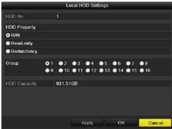
Figure 14-15 Set HDD Property
Step 3 Set the HDD property to R/W, Read-only or Redundancy.
Step 4 Click the OK buon to save the sengs and exit the interface.
Step 5 In the HDD Informaon menu, the HDD property will be displayed in the list.

At least 2 hard disks must be added on your DVR when you want to set a HDD to Redundancy, and there is one HDD with R/W property.
14.4 Configuring Quota Mode
Purpose
Each camera can be congured with allocated quota for the storage of recorded les.
Steps
Step 1 Enter the Storage Mode interface.
Menu > HDD > Advanced
Step 2 Click the Storage Mode tab.
Step 3 Set the Mode to Quota, as shown in Figure 14-16.

The DVR must be rebooted to enable the changes to take eect.
![Mode Quota Camera [A1] Camera 01 Used Record Capacity 51.00GB Used Picture Capacity 2048.00MB HDD Capacity (GB) 931 Max. Record Capacity (G... 0 Max. Picture Capacity (GB) 0 ▲ Free Quota Space 931 GB Enable HDD Sleeping](/content/2026/05/1005813/images/e7087be7dd8c9df0852894244c4b5e88dd7f0ae66efbd3fb8b81e8b1f4866072.jpg)
Figure 14-16 Storage Mode Sengs Interface
Step 4 Select a camera for which you want to congure quota.
Step 5 Enter the storage capacity in the text eld of Max. Record Capacity (GB).
Step 6 You can copy the quota sengs of the current camera to other cameras if required. Click the Copy buon to enter the Copy Camera interface, as shown in Figure 14-17.

Figure 14-17 Copy Sengs to Other Camera(s)
Step 7 Select the camera (s) to be congured with the same quota sengs. You can also click the checkbox of Analog to select all cameras.
Step 8 Click the OK buon to nish the Copy sengs and back to the Storage Mode interface.
Step 9 Click the Apply buon to apply the sengs.

If the quota capacity is set to 0, then all cameras will use the total capacity of HDD for record.
14.5 Configuring Cloud Storage
Purpose
The cloud storage facilitates you to upload and download the recorded les at any me and any place, which can highly enhance the eciency.

Cloud storage is only applicable to HQHI-F/N and HUHI-F/N series DVR.
Step 1 Enter the Cloud Storage interface
Menu > HDD > General > Cloud Storage
Step 2 Check the Enable Cloud checkbox to enable the feature.
Step 3 Select the Cloud Type from the dropdown list to One Drive, Google Drive or Drop Box.
![HDD Information Cloud Storage Enable Cloud Cloud Type OneDrive Authorization Code ABCDE Status Offline Use a mobile browser to scan the OR code to log in the selected cloud to get the authorization code. Camera [A1] Camera 01 Upload Type Record Enable Event Upload *Note: Only sub-stream recorded files can be uploaded to the Cloud Storage. Please configure the event triggered recording schedule and enable the corresponding event type. Copy Apply Back](/content/2026/05/1005813/images/eb24c0e49bbad0c3305fac23fd888b1c915fee95539242bd00c38f524eac7c73.jpg)
Figure 14-18 Cloud Storage Interface
Step 4 According to the prompts, you are required to use a mobile browser to scan the QR code to log in the selected cloud to get the authencaon code. And then copy the authencaon code to the Authencaon Code text led.
Step 5 Click Apply and then back to the main menu.
Step 6 Enter the cloud storage interface again about 20s later. When the Status shows online, it indicates the successful registraon.
Step 7 Congure the recording schedule.
Back to enter the record interface, choose a certain camera from the Camera dropdown list and check the Enable Schedule checkbox to enable the schedule recording. For detailed recording schedule, refer to 5.2 Conguring Recording and Capture Schedule.
![Record Camera [A1] Camera 01 Enable Schedule Mon 1 Tue 2 Wed 3 Thu 4 Fri 5 Sat 6 Sun 7 Edit Continuous Event Motion Alarm M | A M & A POS None Copy Apply Back](/content/2026/05/1005813/images/15ea1c3bcc631ab45923c13222f9dcd8d00e30c20951a8043bd1c7c039e1ecb4.jpg)
Figure 14-19 Record Schedule

The POS recording is supported by DS-7300/8100HQHI-F/N and DS-7300/8100/9000HUHI-F/N series DVR only.
Step 8 Upload the event triggered recording les to the cloud storage.
1) Back to enter the cloud storage interface, and select the camera you have set in the recording schedule interface.
2) Select the upload type in the Upload Type text led.
3) Check the Enable Event Upload checkbox.
4) Click Apply to nish the sengs.
![HDD Information Cloud Storage Enable Cloud ✓ Cloud Type OneDrive Authorization Code ABCDE Status Offline Use a mobile browser to scan the OR code to log in the selected cloud to get the authorization code. Camera [A1] Camera 01 Upload Type Record Enable Event Upload ✓ *Note: Only sub-stream recorded files can be uploaded to the Cloud Storage. Please configure the event triggered recording schedule and enable the corresponding event type. Copy Apply Back](/content/2026/05/1005813/images/26075a65721a5c38a0202bf6c2a7cb0ce42dbe6d55d45d667dcf0830aa35a571.jpg)
Figure 14-20 Upload to Cloud Storage Interface

- Only the sub-stream recorded les can be uploaded to the Cloud Storage.
- Please congregate the event triggered recording schedule and enable the corresponding event type.
Step 9 (Oponal) You can click the Copy buon to copy the cloud storage settings to other cameras. You can also click the checkbox of Analog/IP Camera to select all cameras. Click OK buon to back to the cloud storage interface and click Apply to nish the sengs.

Figure 14-21 Copy to Interface
14.6 Configuring Disk Clone

This chapter is only applicable to the DVR with eSATA.
Purpose
If the S.M.A.R.T. detecon result declares the HDD is abnormal, you can choose to clone all the data on the HDD to an inserted eSATA disk manually. Refer to Chapter 14.8 Checking S.M.A.R.T. Informaon for details of S.M.A.R.T detecon.
Before you start
An eSATA disk should be connected to the device.
Step 1 Enter the HDD Advanced Seng interface:
Menu > HDD > Advanced
Step 2 Click the Disk Clone tab to enter the disk clone conguring interface.

Figure 14-22 Disk Clone Conguraon Interface
Step 3 Make sure the usage of the eSATA disk is set as Export.
If not, click the Set button to set it. Choose Export and click the OK buon.
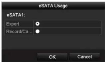
Figure 14-23 Seng eSATA Usage
i NOTE
The capacity of desnaon disk must be the same as that of the clone source disk.
Step 4 Check the checkbox of the HDD to be cloned in the Clone Source list.
Step 5 Click the Clone buon and a message box pops up.

Figure 14-24 Message Box for Disk Clone
Step 6 Click the Yes buon to connue.
You can check the clone progress in the HDD status.
| Label | Capacity | Status | Property | Type | Free Space | Gr... |
| 4 | 931.51GB | Cloning 01% | R/W | Local | 0MB | 1 |
Figure 14-25 Check Disk Clone Progress
14.7 Checking HDD Status
Purpose
You may check the status of the installed HDDs on DVR so as to take immediate check and maintenance in case of HDD failure.
Checking HDD Status in HDD Informaon Interface
Step 1 Enter the HDD Informaon interface.
Menu > HDD > General
Step 2 Check the status of each HDD which is displayed on the list, as shown in Figure 14-26.

Figure 14-26 View HDD Status (1)

If the status of HDD is Normal or Sleeping, it works normally. If the status is Uninialized or Abnormal, please inialize the HDD before use. And if the HDD inializaon is failed, please replace it with a new one.
Checking HDD Status in System Informaon Interface
Step 1 Enter the System Informaon interface.
Menu > Maintenance > System Info
Step 2 Click the HDD tab to view the status of each HDD displayed on the list, as shown in Figure 14-27.
| Label | Status | Capacity | Free Space | Property | Type | Group |
| 1 | Normal | 931.51GB | 900GB | R/W | Local | 1 |
| 17 | Normal | 199.97GB | 182GB | Redundancy | NAS | 1 |
Figure 14-27 View HDD Status (2)
14.8 Checking S.M.A.R.T Information
Purpose
The S.M.A.R.T. (Self-Monitoring, Analysis and Reporng Technology) is a monitoring system for HDD to detect and report on various indicators of reliability in the hopes of ancipang failures.
Step 1 Enter the HDD Detect interface.
Menu > Maintenance > HDD Detect
Step 2 Click the S.M.A.R.T. Setngs tab to enter the interface.
Step 3 Select the HDD to view its S.M.A.R.T. informaon list, as shown in Figure 14-28.

If you want to use the HDD even when the S.M.A.R.T. checking is failed, you can check the checkbox before the Connue to use this disk when self-evaluaon is failed item.
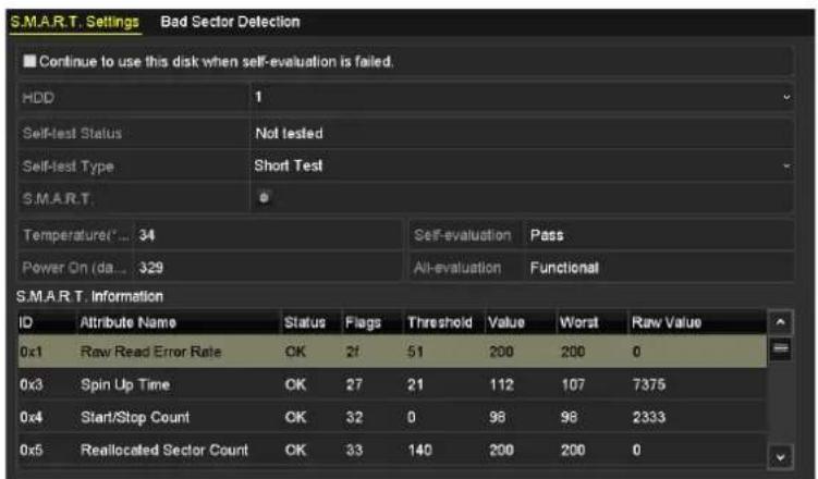
Figure 14-28 S.M.A.R.T Sengs Interface
14.9 Detecting Bad Sector
Purpose
You can detect the bad sector of the HDD to check the status of the HDD.
Step 1 Enter the HDD Detect interface.
Menu>HDD>HDD Detect
Step 2 Click the Bad Sector Detecon tab to enter the interface.
Step 3 Select a HDD and click the Detect buon to start detecng.

Figure 14-29 Bad Sector Detecng
Step 4 You can click the Pause buon to pause the detecon and click the Resume buon to resume the detecon.
Step 5 If there is error informaon about the HDD, you can click the Error Info buon to view the informaon.
14.10 Configuring HDD Error Alarms
Purpose
You can congregate the HDD error alarms when the HDD status is Uninialized or Abnormal.
Step 1 Enter the Excepon interface.
Menu > Conguraon > Excepons
Step 2 Select the Excepon Type to HDD Error from the dropdown list.
Step 3 Check the checkbox(s) below to select the linkage acon(s) for HDD error, as shown in Figure 14-30.
The linkage acons can be selected to: Audible Warning, Nofy Surveillance Center, Send Email and Trigger Alarm Output.

Figure 14-30 Congure HDD Error Alarm
Step 4 When the Trigger Alarm Output is selected, you can also select the alarm output to be triggered from the list below.
Step 5 Click the Apply buon to save the sengs.
Chapter 15 Camera Settings
15.1 Configuring OSD Settings
Purpose
You can congregate the OSD (On-Screen Display) sengs for the camera, including date/me, camera name, etc.
Step 1 Enter the OSD Conguraon interface.
Menu > Camera > OSD
Step 2 Select the camera to congure OSD sengs.
Step 3 Edit the Camera Name in the text eld.
Step 4 Congure the Display Name, Display Date and Display Week by checking the checkbox.
Step 5 Select the Date Format, Time Format, Display Mode and the OSD Font.
![OSD Configuration Camera [A1] Camera 01 Camera Name Camera 01 Display Name Display Date Display Week Date Format MM-DD-YYYY Time Format 24-hour Display Mode Non-Transparent & Not Flashing OSD Font 32x32](/content/2026/05/1005813/images/1af5b954ccb958b69d4f5d881b915ff6abb8d3548c69e345046be488e801053f.jpg)
Figure 15-1 OSD Conguraon Interface
Step 6 You can use the mouse to drag the text frame on the preview window to adjust the OSD posion.
Step 7 Copy Camera Sengs
1) If you want to copy the OSD sengs of the current camera to other cameras, click the Copy buon to enter the Copy Camera interface, as shown in Figure 15-2.

Figure 15-2 Copy Sengs to Other Cameras
2) Select the camera (s) to be congured with the same OSD sengs. You can also check the checkbox of Analog to select all cameras.
3) Click the OK buon to nish the Copy sengs and back to the OSD Conguraon interface.
Step 8 Click the Apply buon to apply the sengs.
15.2 Configuring Privacy Mask
Purpose
You are allowed to congregate the four-sided privacy mask zones that cannot be viewed or recorded by the operator.
Step 1 Enter the Privacy Mask Sengs interface.
Menu > Camera > Privacy Mask
Step 2 Select the camera to set privacy mask.
Step 3 Check the checkbox of Enable Privacy Mask to enable this feature.
![Privacy Mask Settings Camera [A1] Camera 01 Enable Privacy Mask Clear All Clear Zone 1 Clear Zone 2 Clear Zone 3 Clear Zone 4](/content/2026/05/1005813/images/7e61c795a2e4f21a5af918716867700509801943d3da8b42d818aeee49aaa82f.jpg)
Figure 15-3 Privacy Mask Sengs Interface
Step 4 Use the mouse to draw a zone on the window. The zones will be marked with dierent frame colors.

Up to 4 privacy mask zones can be congured, and the size of each area can be adjusted.
Step 5 The congured privacy mask zones on the window can be cleared by clicking the corresponding Clear Zone1-4 icons on the right side of the window, or click Clear All to clear all zones.
![Privacy Mask Settings Camera [A1] Camera 01 Enable Privacy Mask Clear All Clear Zone 1 Clear Zone 2 Clear Zone 3 Clear Zone 4](/content/2026/05/1005813/images/d81a17fde8050cd98be2d772f88aac5962baa4fe37c9e22ff081c8c9a42972c4.jpg)
Figure 15-4 Set Privacy Mask Area
Step 6 You can click the Copy buon to copy the privacy mask sengs of the current camera to other cameras.
Please refer to step 7 of Chapter 15.1 Conguring OSD Sengs.
Step 7 Click the Apply buon to save the sengs.
15.3 Configuring Video Parameters
15.3.1 Configuring Image Settings
Step 1 Enter the Image Sengs interface.
Menu > Camera > Image
Step 2 Select the Image Sengs tab.

Figure 15-5 Image Sengs Interface (Analog Camera)
![Camera [D2] IPdome Time Segment 1 00:00-24:00 Mode Custom Brightness 128 °C Contrast 153 °C Saturation 204 °C Default Copy Apply Back](/content/2026/05/1005813/images/1c9b79275b2bb0c2f4930b5962325d525610e33cea5c2414674dba1a2448a53f.jpg)
Figure 15-6 Image Sengs Interface (IP Camera)
Step 3 Select the camera to set image parameters.
Step 4 Two periods for dierent image sengs are provided, select the period name in the dropdown list.

The me periods cannot be overlapped with each other.
Step 5 Select the mode from the drop-down list of Mode, there are four modes selectable for the analog cameras: Standard, Indoor, Dim Light and Outdoor.
Step 6 Adjust the image parameters according to actual needs. The parameters include Brightness, Contrast, Saturaon, Hue, Sharpness and Denoising for the analog cameras and Brightness,
Contrast and Saturaon for the IP cameras. You can also click Restore to set the parameters to the default sengs.
Step 7 You can click Copy to copy the image sengs of the current camera to other cameras.
Step 8 Click Apply to save the sengs.
15.3.2 Configuring Camera Parameters Settings

This secon is applicable to -F series DVR.
Step 1 Enter the Image Sengs interface.
Menu > Camera > Image
Step 2 Select the Camera Parameters Sengs tab.
![Image Settings Camera Parameters Settings Camera [A1] Camera 01 Day to Ni... Night to D... IR Light B... Default Copy Apply Back](/content/2026/05/1005813/images/71093945724a38415f1f0059bd1f2d4de4fb752ccc09343a06ad29ffd6c2e8ff.jpg)
Figure 15-7 Camera Parameters Sengs
Step 3 Select the Camera from the dropdown list.
Step 4 Adjust the camera parameters. The parameters include Day to Night Sensitivity, Night to Day Sensitivity and IR Light Brightness for the analog cameras. You can also click Default to set the parameters to the default sengs.
Step 5 You can click Copy to copy the parameters of the current camera to other analog cameras.
Step 6 Click Apply to save the sengs.
i NOTE
● The camera parameters sengs is only applicable for ananlog cameras.
- The Day to Night Sensitivity, Night to Day Sensitivity and IR Light Brightness funcons must be supported by the connected analog camera. You cannot set the parameters if the connected analog camera does not support them or there is no video signal.
● The parameters are saved to the connected analog camera and are not saved to the DVR.
- The default value of Day to Night Sensitivity, Night to Day Sensitivity and IR Light Brightness is 5. The eecve value ranges from 1 to 9.
- If you exit from the interface and enter it again, the parameters displayed are those you have set the last me.
- The DVR connects to the analog camera via coaxitron and there is no response mechanism. Even if the coaxitron is abnormal, the parameters are sll displayed to be set successfully.
Chapter 16 DVR Management and Maintenance
16.1 Viewing System Information
Step 1 Enter the System Informaon interface.
Menu > Maintenance > System Info
Step 2 You can click the Device Info, Camera, Record, Alarm, Network and HDD tabs to view the system informaon of the device.
| Device Name | Embedded Net DVR |
| Model | DS-9016HUHI-F8/N |
| Serial No. | 1620160516CCWR583574624WCVU |
| Firmware Version | V3.4.80, Build 160827 |
| Hardware Version | 0x81d00 |
| Please scan the QR code via iVMS client. | |
Figure 16-1 System Informaon Interface
i NOTE
● This alarm informaon is not available for the DS-7100 and DS-7200HGHI series.
● You can view the hardware version in the Device Informaon interface.
16.2 Searching Log Files
Purpose
The operaon, alarm, excepon and informaon of the DVR can be stored in log les, which can be viewed and exported at any me.
Step 1 Enter the Log Search interface.
Menu > Maintenance > Log Informaon

Figure 16-2 Log Search Interface
Step 2 Set the log search conditions to rene your search, including the Start Time, End Time, Major Type and Minor Type.
Step 3 Click the Search buon to start search log les.
Step 4 The matched log les will be displayed on the list shown below.

Up to 2000 log les can be displayed each me.
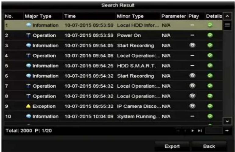
Figure 16-3 Log Search Results
Step 5 You can click the ☑ buon of each log or double-click it to view its detailed informaon. And you can also click the ☑ buon to view the related video les if available.

Figure 16-4 Log Informaon Interface
Step 6 If you want to export the log les, click the Export buon to enter the Export menu, as shown in Figure 16-5.

Figure 16-5 Export Log Files
Step 7 Select the backup device from the dropdown list of Device Name.
Step 8 Click the Export to export the log les to the selected backup device.
You can click the New Folder buon to create new folder in the backup device, or click the Format buon to format the backup device before log export.
i NOTE
- Please connect the backup device to DVR before operang log export.
- The log les exported to the backup device are named by exporng me, e.g., 20110514124841logBack.txt.
16.3 Importing/Exporting IP Camera Info
Purpose
The informaon of added IP camera can be generated into an excel le and exported to the local device for backup, including the IP address, manage port, password of admin, etc. And the exported le can be edited on your PC, like adding or deleng the content, and copy the seng to other devices by imporng the excel le to it.
Step 1 Enter the camera management interface.
Menu > Camera > Camera
Click the IP Camera Import/Export tab, the content of detected plugged external device appears.
Step 2 Click the Export buon to export conguraon les to the selected local backup device.
Step 3 To import a conguraon le, select the le from the selected backup device and click the Import buon. Aer the imporg process is completed, you must reboot the DVR.
16.4 Importing/Exporting Configuration Files
Purpose
The conguraon les of the DVR can be exported to local device for backup; and the conguraon les of one DVR can be imported to mulple DVR devices if they are to be congured with the same parameters.
Step 1 Enter the Import/Export Conguraon File interface.
Menu > Maintenance > Import/Export
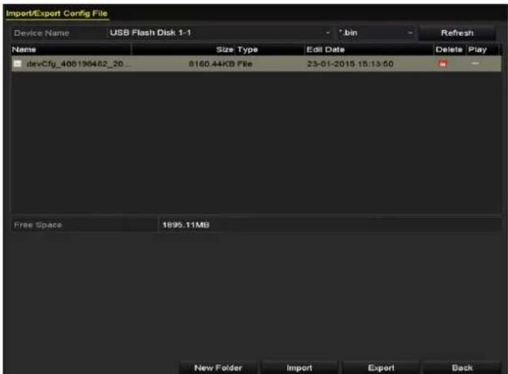
Figure 16-6 Import/Export Conguraon File
Step 2 Click the Export buon to export conguraon les to the selected local backup device.
Step 3 To import a conguraon le, select the le from the selected backup device and click the Import buon. Aer the import process is completed, you must reboot the DVR.

Aer having nished the import of conguraon les, the device will reboot automacally.
16.5 Upgrading System
Purpose
The rmware on your DVR can be upgraded by local backup device or remote FTP server.
16.5.1 Upgrading by Local Backup Device
Step 1 Connect your DVR with a local backup device where the update rmware le is located.
Step 2 Enter the Upgrade interface.
Menu > Maintenance > Upgrade
Step 3 Click the Local Upgrade tab to enter the Local Upgrade interface, as shown in Figure 16-7.

Figure 16-7 Local Upgrade Interface
Step 4 Select the update le from the backup device.
Step 5 Click the Upgrade buon to start upgrading.
Step 6 Aer the upgrading is complete, reboot the DVR to acvate the new rmware.
16.5.2 Upgrading by FTP
Before you start
Congure PC (running FTP server) and DVR to the same Local Area Network. Run the 3 rd -party TFTP soware on the PC and copy the rmware into the root directory of TFTP.
Step 1 Enter the Upgrade interface.
Menu > Maintenance > Upgrade
Step 2 Click the FTP tab to enter the Local Upgrade interface, as shown in Figure 16-8.

Figure 16-8 FTP Upgrade Interface
Step 3 Enter the FTP Server Address in the text eld.
Step 4 Click the Upgrade buon to start upgrading.
Step 5 Aer the upgrading is complete, reboot the DVR to acvate the new rmware.
16.6 Restoring Default Settings
Step 1 Enter the Default interface.
Menu > Maintenance > Default

Figure 16-9 Restore Defaults
Step 2 Select the restoring type from the following three opons.
Restore Defaults: Restore all parameters, except the network (including IP address, subnet mask, gateway, MTU, NIC working mode, default route, server port, etc.) and user account parameters, to the factory default sengs.
Factory Defaults: Restore all parameters to the factory default sengs.
Restore to Inacve: Restore the device to the inacve status.
Step 3 Click the OK buon to restore the default sengs.

The device will reboot automacally aer restoring to the default sengs.
Chapter 17 Others
17.1 Configuring General Settings
Purpose
You can congregate the output resolution, system me, mouse pointer speed, etc.
Step 1 Enter the General Sengs interface.
Menu > Conguraon > General
Step 2 Select the General tab.

Figure 17-1 General Sengs Interface (for DS-7300/8100/9000HUHI-F/N Series)

Figure 17-2 General Sengs Interface (for Simultaneous VGA and HDMI Output)

Figure 17-3 General Sengs Interface (for Independent VGA and HDMI Output)
Step 3 Congure the following sengs:
● Language: The default language used is English.
● Output Standard: Select the output standard to be PAL or NTSC.
- VGA/HDMI Resoluon: Select the output resoluon, which must be the same with the resoluon of the VGA/HDMI display.
i NOTE
- For DS-7300/8100/9000HUHI-F/N series, VGA/HDMI1 Resoluon and HDMI2 Resoluon can be congured separately. Up to 1920 × 1080/60 Hz resoluon is supported for VGA/HDMI1 output and up to 4K (3840 × 2160)/30 Hz resoluon is supported for HDMI2 output.
- For DS-7608/7616HUHI-F/N and DS-7300/8100HQHI-F/N series DVR, the HDMI and VGA interfaces can be congured to be simultaneous or independent (Refer to Chapter 17.4 Conguring More Sengs for reference). If you have congured HDMI/VGA simultaneous output, you can set the VGA/HDMI Resoluon. If you have congured independent HDMI and VGA output, you can set the VGA Resoluon and HDMI Resolution independently. Up to 1920 × 1080 / 60 Hz resoluon is supported for VGA output and up to 4K ( 3840 × 2160 )/30 Hz resoluon is supported for HDMI output.
● Time Zone: Select the me zone.
● Date Format: Select the date format.
● System Date: Select the system date.
● System Time: Select the system me.
● Mouse Pointer Speed: Set the speed of mouse pointer; 4 levels are congorable.
● Enable Wizard: Enable/disable the Wizard when the device starts up.
- Enable Password: Enable/disable the use of the login password.

For -F series DVR, if you check the checkbox of Enable Password, every me when you log in to the DVR, the Unlock Paern interface will pop up. If you uncheck the checkbox of Enable Password, when you log in to the DVR, the Unlock Paern interface will not pop up.
Step 4 Click the Apply buon to save the sengs.
17.2 Configuring RS-232 Serial Port

The RS-232 serial port is supported by DS-7300/8100HQHI-F/N and DS-7300/8100/9000HUHI-F/N series DVR.
Purpose
The RS-232 port can be used in two ways:
- Parameters Conguraon: Connect a PC to the DVR through the PC serial port. Device parameters can be congured by using soware such as HyperTerminal. The serial port parameters must be the same as the NVR's when connecng with the PC serial port.
- Transparent Channel: Connect a serial device directly to the DVR. The serial device will be controlled remotely by the PC through the network and the protocol of the serial device.
Step 1 Enter the RS-232 Sengs interface.
Menu >Conguraon> RS-232

Figure 17-4 RS-232 Sengs Interface
Step 2 Congure RS-232 parameters, including baud rate, data bit, stop bit, parity, ow control and usage.
Step 3 Click the Apply buon to save the sengs.
17.3 Configuring DST Settings
Step 1 Enter the General Sengs interface.
Menu >Conguraon>General
Step 2 Choose DST Sengs tab.

Figure 17-5 DST Sengs Interface
You can check the checkbox before the Auto DST Adjustment item.
Or you can manually check the Enable DST checkbox, and then you choose the date of the DST period.
17.4 Configuring More Settings
Step 1 Enter the General Sengs interface.
Menu > Conguraon > General
Step 2 Click the More Sengs tab to enter the More Sengs interface, as shown in the following gures.

Figure 17-6 More Sengs Interface (1)

Figure 17-7 More Sengs Interface (2)

Figure 17-8 More Sengs Interface (3)

Figure 17-9 More Sengs Interface (4)
Step 3 Congure the following sengs:
● Device Name: Edit the name of DVR.
- Device No.: Edit the serial number of DVR. The Device No. can be set in the range of 1\~255, and the default No. is 255.
- Auto Logout: Set meout me for menu inactivity. E.g., when the meout me is set to 5 Minutes, then the system will exit from the current operaon menu to live view screen aer 5 minutes of menu inactivity.
- CVBS Output Brightness: Adjust the video output brightness via the CVBS interface.

The CVBS Output is provided for the DS-7200/7300/8100HQHI-F/N and DS-7200/7600/7300/8100/9000HUHI-F/N series DVR only.
- Enable HDMI/VGA Simultaneous Output: For DS-7608/7616HUHI-F/N and DS-7300/8100HQHI-F/N series DVR, the HDMI and VGA interfaces can be congured to be simultaneous or independent. You can check the checkbox to enable HDMI/VGA simultaneous output or uncheck it to remain independent output of HDMI and VGA interfaces.
- Menu Output Mode: You can choose the menu display on dierent video output.

- For DS-7608/7616HUHI-F/N and DS-7300/8100HQHI-F/N series DVR, if you have congured HDMI/VGA simultaneous output, you can select Auto and HDMI/VGA for the menu output mode. If you have congured independent HDMI and VGA output, you can select Auto, HDMI and VGA for the menu output mode.
For DS-7300/8100/9000HUHI-F/N series, Auto, HDMI1/VGA, and HDMI2 are selectable. - For HGHI-F/N, HGHI-F, DS-7104/7108/7204/7208HQHI-F/N and DS-7200/7604HUHI-F/N series DVR, Auto and HDMI/VGA are selectable.
- Encoding Mode: For DS-7100/7200HGHI-E series DVR, you can select the encoding mode. When the non-real-me mode is selected, the max. frame rate (Menu>Record>Parameters) can be set to 15 fps only.
- Main CVBS Scaling: You can check the checkbox to enable main CVBS scaling.
● Enhanced VCA Mode: For DS-7208/7216HUHI-F/N series DVR, you can check the checkbox to enable enhanced VCA mode. When you enable it and click Apply, the aenon box pops up as below. Click Yes to apply the funcon and reboot the device.

Figure 17-10 Enable Enhanced VCA Mode
If the enhanced VCA mode has been enabled, you can disable it by unchecking the checkbox. When you disable it and click Apply, the aenon box pops up as below. Click Yes to apply the funcon and reboot the device.

Figure 17-11 Disable Enhanced VCA Mode
Step 4 Click the Apply buon to save the sengs.
17.5 Managing User Accounts
Purpose
There is a default account in the DVR: Administrator. The Administrator user name is admin and the password is set when you start the device for the rst me. The Administrator has the permission to add and delete user and congure user parameters.
17.5.1 Adding a User
Step 1 Enter the User Management interface.
Menu >Conguraon>User

Figure 17-12 User Management Interface
Step 2 Click the Add buon to enter the Add User interface.
![Add User User Name example 1 Password ****** Confirm ****** Level Guest User's MAC Address 00 :00 :00 :00 :00 :00 ✓ Valid password range [8-16]. You can use a combination of numbers, lowercase, uppercase and special character for your password with at least two kinds of them contained. OK Cancel](/content/2026/05/1005813/images/90b086ccf04cd018fc9edb7874aa62f7f0ffc47aff89bcad31504fbab3896c73.jpg)
Figure 17-13 Add User Menu
Step 3 Enter the informaon for new user, including User Name, Password, Conrm, Level and User's MAC Address.
Password: Set the password for the user account.

WARNING
STRONG PASSWORD RECOMMENDED-We highly recommend you create a strong password of your own choosing (Using a minimum of 8 characters, including at least three of the following categories: upper case leers, lower case leers, numbers, and special characters.) in order to increase the security of your product. And we recommend you reset your password regularly, especially in the high security system, reseng the password monthly or weekly can beer protect your product.
Level: Set the user level to Operator or Guest. Dierent user levels have dierent operang permission.
- Operator: The Operator user level has permission of Two-way Audio in Remote Conguraon and all operang permission in Camera Conguraon by default.
- Guest: The Guest user has no permission of Two-way Audio in Remote Conguraon and only has the local/remote playback in the Camera Conguraon by default.
User's MAC Address: The MAC address of the remote PC which logs onto the DVR. If it is congured and enabled, it only allows the remote user with this MAC address to access the DVR.
Step 4 Click the OK buon to save the sengs and go back to the User Management interface. The added new user will be displayed on the list, as shown in Figure 17-14.

Figure 17-14 Added User Listed in User Management Interface
Step 5 You can assign permissions for the added user.
1) Select the user from the list and then click ✅ to enter the Permission Sengs interface, as shown in Figure 17-15.

Figure 17-15 User Permission Sengs Interface
2) Set the operang permission of Local Conguraon, Remote Conguraon and Camera Conguraon for the user.
Local Conguraon
- Local Log Search: Searching and viewing logs and system informaon of device.
-
Local Parameters Sengs: Conguring parameters, restoring factory default parameters and imporng/exporng conguraon les.
-
Local Camera Management: Enabling and disabling analog camera (s). Adding, deleng and eding of network camera (s). This funcon is supported by HDVR series.
- Local Advanced Operaon: Operang HDD management (initializing HDD, seng HDD property), upgrading system rmware.
- Local Shutdown /Reboot: Shung down or reboong the device.
Remote Conguraon
- Remote Log Search: Remotely viewing logs that are saved on the device.
- Remote Parameters Sengs: Remotely conging parameters, restoring factory default parameters and imporg/exporg conguraon les.
- Remote Camera Management: Remotely enabling and disabling analog camera (s), and adding, deleng and eding of network camera (s). This funcon is supported by HDVR series.
- Remote Serial Port Control: Conguring sengs for RS-485 port.
- Remote Video Output Control: Sending remote control panel signal.
- Two-way Audio: Realizing two-way radio between the remote client and the device.
- Remote Alarm Control: Remotely arming (nofy alarm and excepon message to the remote client) and controlling the alarm output.
- Remote Advanced Operaon: Remotely operang HDD management (initializing HDD, seng HDD property), upgrading system rmware.
- Remote Shutdown/Reboot: Remotely shung down or reboong the device.
Camera Conguraon
- Remote Live View: Remotely viewing live video of the selected camera (s).
- Local Manual Operaon: Locally starng/stopping manual recording, picture capturing and alarm output of the selected camera (s).
- Remote Manual Operaon: Remotely starng/stopping manual recording, picture capturing and alarm output of the selected camera (s).
- Local Playback: Locally playing back recorded les of the selected camera (s).
- Remote Playback: Remotely playing back recorded les of the selected camera (s).
- Local PTZ Control: Locally controlling PTZ movement of the selected camera (s).
- Remote PTZ Control: Remotely controlling PTZ movement of the selected camera (s).
- Local Video Export: Locally exporng recorded les of the selected camera (s).

Local Camera Management is provided for the IP cameras only.
3) Click OK to save the sengs and exit.
17.5.2 Deleting a User
Step 1 Enter the User Management interface.
Menu >Conguraon>User
Step 2 Select the user to be deleted from the list, as shown in Figure 17-16.

Figure 17-16 User List
Step 3 Click 📄 to delete the selected user account.
17.5.3 Editing a User
Purpose
For the added user accounts, you can edit the parameters.
Step 1 Enter the User Management interface.
Menu >Conguraon>User
Step 2 Select the user to be edited from the list, as shown in Figure 17-16.
Step 3 Click the 📋 icon to enter the Edit User interface, as shown in Figure 17-17.
![Edit User User Name example 1 Change Password Password ******** Confirm ******** Level Guest User's MAC Address 00 :00 :00 :00 :00 :00 ✓ Valid password range [8-16]. You can use a combination of numbers, lowercase, uppercase and special character for your password with at least two kinds of them contained. OK Cancel Edit User User Name admin Old Password ******** Change Password ✓ Password ******** Confirm ******** Enable Unlock Pattern ✓ Draw Unlock Pattern ✓ Export GUID ✓ User's MAC Address 00 :00 :00 :00 :00 :00 ✓ Valid password range [8-16]. You can use a combination of numbers, lowercase, uppercase and special character for your password with at least two kinds of them contained. OK Cancel](/content/2026/05/1005813/images/e0c2bd21c51397dbef42fbb1cddb63e3368e77469bbbcfc6260ab0583ece04cc.jpg)
Figure 17-17 Edit User Interface
Step 4 Edit the corresponding parameters.
- Operator and Guest
You can edit the user informaon, including user name, password, permission level and MAC address. Check the checkbox of Change Password if you want to change the password, and input the new password in the text eld of Password and Conrm. A strong password is recommended.
- Admin
You are only allowed to edit the password and MAC address. Check the checkbox of Change Password if you want to change the password, and input the correct old password, and the new password in the text eld of Password and Conrm.

WARNING
STRONG PASSWORD RECOMMENDED-We highly recommend you create a strong password of your own choosing (Using a minimum of 8 characters, including at least three of the following categories: upper case leers, lower case leers, numbers, and special characters.) in order to increase the security of your product. And we recommend you reset your password regularly, especially in the high security system, reseng the password monthly or weekly can beer protect your product.

NOTE
Hold the icon and you can see the clear text of the password. Release the mouse and the content of the password restores invisible.
Step 5 Edit the unlock paern for the admin user account.
1) Check the checkbox of Enable Unlock Paern to enable the use of unlock paern when logging in to the device.
2) Use the mouse to draw a paern among the 9 dots on the screen. Release the mouse when the paern is done.
3) Conrm the paern again with the mouse.

Please refer to Chapter 2.3.1 Conguring the Unlock Paern for detailed instrucons.
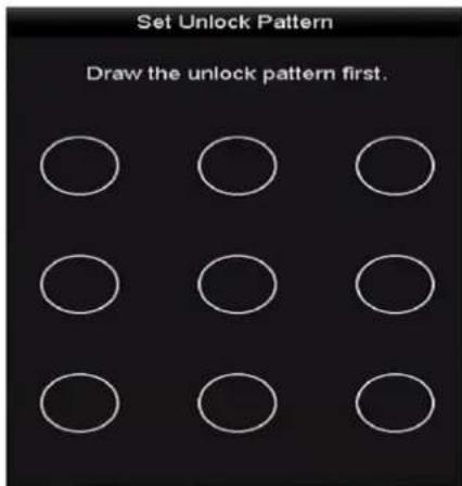
Figure 17-18 Set Unlock Paer for Admin User
Step 6 (Oponal) Click icon after Draw Unlock Paern to modify the paern.
Step 7 (Oponal) Click icon aer Export GUID to pop up the Reset Password interface. Click Export buon to export GUID to the USB ash disk for retrieving the forgoen password. Then a GUID le will be saved in the USB ash disk.
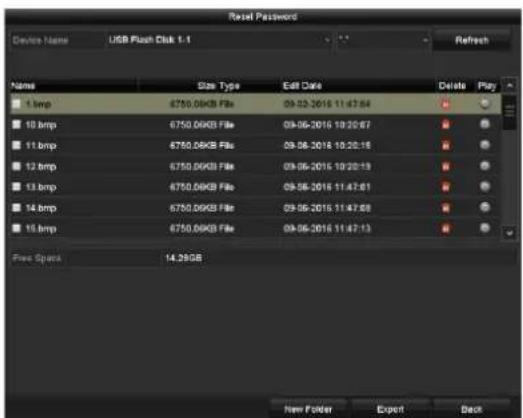
Figure 17-19 Export GUID

You must input the correct old password of the admin before exporng GUID.
Step 8 Click the OK buon to save the sengs and exit from the menu.
Step 9 (Oponal) For the Operator or Guest user account, you can also click the user on the User Management interface to edit the permission.
Chapter 18 Appendix
18.1 Specifications
| Model | DS-7104HGHI-E1 | DS-7108HGHI-E1 | DS-7116HGHI-E1 | |
| Video/Audio input | Video compression | H.264+/H.264 | ||
| Analog and HDTVIVideo input | 4-ch | 8-ch | 16-ch | |
| BNC interface (1.0 Vp-p, 75 Ω), supporting coaxitron conncon | ||||
| Supported camera types | 720p25, 720p30, CVBS | |||
| Audio compression | G.711u | |||
| Audio input/Two-way audio input | 1-ch, RCA (2.0 Vp-p, 1 KΩ) | |||
| Video/Audio output | HDMI/VGA output | 1920 × 1080/60Hz,1280 × 1024/60Hz, 1280 × 720/60Hz, 1024 × 768/60Hz | ||
| Encoding resoluon | 720p/VGA/WD1/4CIF/CIF | |||
| Frame rate | Main stream: 720p/VGA/WD1/4CIF/CIF@25fps (P)/30fps (N) | |||
| Sub-stream: 2CIF@6fps; CIF/QVGA/QCIF@25 fps (P)/30fps (N) | Sub-stream: 4CIF/2CIF@6fps; CIF/QVGA/QCIF@25fps (P)/30fps (N) | |||
| Video bit rate | 32 Kbps to 4 Mbps | |||
| Audio output | 1-ch, RCA (Linear, 1 KΩ) | |||
| Audio bit rate | 64 Kbps | |||
| Dual-stream | Support | |||
| Stream type | Video, Video & Audio | |||
| Synchronous playback | 4-ch | 8-ch | 16-ch | |
| Network management | Remote connecons | 32 | 128 | |
| Network protocols | TCP/IP, PPPoE, DHCP, Hik Cloud P2P, DNS, DDNS, NTP, SADP, SMTP, NFS, iSCSI, UPnPTM, HTTPS | |||
| Hard disk | SATA | 1 SATA interface | ||
| Capacity | Up to 6 TB capacity for each disk | |||
| External interface | Network interface | 1, 10M/100M self-adapve Ethernet interface | ||
| USB interface | 2 × USB 2.0 | |||
| General | Power supply | 12 VDC | ||
| Consumpon (without HDD) | ≤ 8 W | ≤ 12 W | ≤ 20 W | |
| Working temperature | -10 °C to +55 °C (14 °F to 131 °F) | |||
| Working humidity | 10% to 90% | |||
| Dimensions | 200 × 200 × 45 mm (7.9 × 7.9 × 1.8 inch) | 285 × 210 × 45 mm (11.2 × 8.3 × 1.8 | ||
| (W × D × H) | inch) | |||
| Weight (without HDD) | ≤ 0.8 kg (1.8 lb) | ≤ 1.2 kg (2.6 lb) | ||

Each two video channels are grouped in sequence, e.g., CH01 and CH02, CH03 and CH04...; and each two channels in the same group must be connected with the same type of video source (HDTVI or CVBS). The above informaon is for reference only. Please refer to the specic conguraon of the device.
| Model | DS-7204HGHI-E1 | DS-7208HGHI-E1 | DS-7216HGHI-E1 | |
| Video/ Audio input | Video compression | H.264+/H.264 | ||
| Analog and HDTVI video input | 4-ch | 8-ch | 16-ch | |
| BNC interface (1.0 Vp-p, 75 Ω), supporting coaxitron conncon | ||||
| Supported camera types | 720p25, 720p30, CVBS | |||
| IP video input | 1-ch | 2-ch | ||
| Up to 720p resoluon | Up to 1080p resoluon | |||
| Audio compression | G.711u | |||
| Audio input/Two-way audio input | 1-ch, RCA (2.0 Vp-p, 1 KΩ) | |||
| Video/ Audio output | HDMI/VGA output | 1920 × 1080/60Hz, 1280 × 1024/60Hz, 1280 × 720/60Hz, 1024 × 768/60Hz | ||
| Encoding resoluon | 720p/VGA/WD1/4CIF/CIF | |||
| Frame rate | Main stream: 720p/VGA/WD1/4CIF/CIF@25fps (P)/30fps (N) | |||
| Sub-stream: 2CIF@6fps; | Sub-stream: 4CIF/2CIF@6fps; | |||
| CIF/QVGA/QCIF@25fps (P)/30fps (N) | CIF/QVGA/QCIF@25fps (P)/30fps (N) | |||
| Video bit rate | 32 Kbps to 4 Mbps | |||
| Audio output | 1-ch, RCA (Linear, 1 KΩ) | |||
| Audio bit rate | 64 Kbps | |||
| Dual-stream | Support | |||
| Stream type | Video, Video & Audio | |||
| Synchronous playback | 4-ch | 8-ch | 16-ch | |
| Network management | Remote conncons | 32 | 128 | |
| Network protocols | TCP/IP, PPPoE, DHCP, Hik Cloud P2P, DNS, DDNS, NTP, SADP, SMTP, NFS, iSCSI, UPnPTM, HTTPS | |||
| Hard disk | SATA | 1 SATA interface | ||
| Capacity | Up to 6 TB capacity for each disk | |||
| External interface | Network interface | 1, 10M/100Mbps self-adapve Ethernet interface | ||
| USB interface | 2 × USB2.0 | |||
| General | Power supply | 12 VDC | ||
| Consumpon (without HDD) | ≤ 8 W | ≤ 12 W | ≤ 20 W | |
| Working temperature | -10 °C to +55°C (14 °F to 131°F) | |||
| Working humidity | 10% to 90% | |||
| Dimensions (W × D × H) | 260 × 222 × 45 mm (10.2 × 8.7 × 1.8 inch) | |||
| Weight (without HDD) | ≤ 1 kg (2.2 lb) | ≤ 1.2 kg (2.6 lb) | ||

Each two video channels are grouped in sequence, e.g., CH01 and CH02, CH03 and CH04...; and each two channels in the same group must be connected with the same type of video source
(HDTVI or CVBS). The above informaon is for reference only. Please refer to the specic conguraon of the device.
| Model | DS-7208HGHI-E2 | DS-7216HGHI-E2 | |
| Video/ Audio input | Video compression | H.264+/H.264 | |
| Analog and HDTVIVideo input | 8-ch | 16-ch | |
| BNC interface (1.0 Vp-p, 75 Ω), supporng coaxitron conncon | |||
| Supported camera types | 720p25, 720p30, CVBS | ||
| IP video input | 2-ch | ||
| Up to 1080p resoluon | |||
| Audio compression | G.711u | ||
| Audio input/Two-way audio in | 1-ch, RCA (2.0 Vp-p, 1 KΩ) | ||
| Video/ Audio output | HDMI/VGA output | 1920 × 1080/60Hz, 1280 × 1024/60Hz, 1280 × 720/60Hz, 1024 × 768/60Hz | |
| Encoding resoluon | 720p/VGA/WD1/4CIF/CIF | ||
| Frame rate | Main stream: 720p/VGA/WD1/4CIF/CIF@25fps (P)/30fps (N) | ||
| Sub-stream: 4CIF/2CIF@6fps; CIF/QVGA/QCIF@25fps (P)/30fps (N) | |||
| Video bit rate | 32 Kbps to 4 Mbps | ||
| Audio output | 1-ch, RCA (Linear, 1 KΩ) | ||
| Audio bit rate | 64 Kbps | ||
| Dual-stream | Support | ||
| Stream type | Video, Video & Audio | ||
| Synchronous playback | 8-ch | 16-ch | |
| Network management | Remote connecons | 128 | |
| Network protocols | TCP/IP, PPPoE, DHCP, Hik Cloud P2P, DNS, DDNS, NTP, SADP, SMTP, NFS, iSCSI, UPnPTM, HTTPS | ||
| Hard disk | SATA | 2 SATA interfaces | |
| Capacity | Up to 6 TB capacity for each disk | ||
| External interface | Network interface | 1, 10M/100M self-adapve Ethernet interface | |
| USB interface | 2 × USB 2.0 | ||
| General | Power supply | 12 VDC | |
| Consumpon (without HDD) | ≤ 12 W | ≤ 20 W | |
| Working temperature | -10 °C to +55 °C (14 °F to 131 °F) | ||
| Working humidity | 10% to 90% | ||
| Dimensions (W × D × H) | 380 × 320 × 48 mm (14.9 × 12.6 × 1.9 inch) | ||
| Weight (without HDD) | ≤ 2 kg (4.4 lb) | ||

Each two video channels are grouped in sequence, e.g., CH01 and CH02, CH03 and CH04...; and each two channels in the same group must be connected with the same type of video source (HDTVI or CVBS). The above informaon is for reference only. Please refer to the specic conguraon of the device.
18.1.4 DS-7100HGHI-F1
| Model | DS-7104HGHI-F1 | DS-7108HGHI-F1 | DS-7116HGHI-F1 | |
| Video/Audio input | Video compression | H.264+/H.264 | ||
| Analog video input | 4-ch | 8-ch | 16-ch | |
| BNC interface (1.0 Vp-p, 75 Ω), supporng coaxitron conncon | ||||
| HDTV I input | 1080P25, 1080P30, 720p25, 720p30 | |||
| AHD input | 720p25, 720p30 | |||
| HDCVI input | 720p25, 720p30 | |||
| CVBS input | Support | |||
| Audio compression | G.711u | |||
| Audio input/Two-way audio input | 1-ch, RCA (2.0 Vp-p, 1 KΩ) | |||
| Video/Audio output | HDMI/VGA output | 1-ch, 1920 × 1080/60Hz,1280 × 1024/60Hz, 1280 × 720/60Hz 1024 × 768/60Hz | ||
| Encoding resoluon | When 1080p Lite mode not enabled: 720p/WD1/4CIF/VGA/CIF When 1080p Lite mode enabled: 1080p lite/720p/WD1/4CIF/VGA/CIF | |||
| Frame rate | Main stream: When 1080p Lite mode not enabled: For 720p stream access: 720p/WD1/4CIF/VGA/CIF@25fps (P)/30fps (N) When 1080p Lite mode enabled: 1080p lite/720p/WD1/4CIF/VGA/CIF@25fps (P)/30fps (N) | |||
| Sub-stream: 2CIF@6fps; CIF/QVGA/QCIF@ 25fps (P)/30fps (N) | Sub-stream: 4CIF/2CIF@6fps; CIF/QVGA/QCIF@25fps (P)/30fps (N) | |||
| Video bit rate | 32 Kbps to 4 Mbps | |||
| Audio output | 1-ch, RCA (Linear, 1 KΩ) | |||
| Audio bit rate | 64 Kbps | |||
| Dual-stream | Support | |||
| Stream type | Video, Video & Audio | |||
| Synchronous playback | 4-ch | 8-ch | 16-ch | |
| Network management | Remote conncons | 32 | 128 | |
| Network protocols | TCP/IP, PPPoE, DHCP, Hik Cloud P2P, DNS, DDNS, NTP, SADP, SMTP, NFS, iSCSI, UPnPTM, HTTPS | |||
| Hard disk | SATA | 1 SATA interface | ||
| Capacity | Up to 6 TB capacity for each disk | |||
| External interface | Network interface | 1, RJ45 10M/100M self-adapve Ethernet interface | ||
| USB interface | Rear panel: 2 × USB 2.0 | |||
| General | Power supply | 12 VDC | ||
| Consumpon (without HDD) | ≤ 8 W | ≤ 12 W | ≤ 20 W | |
| Working temperature | -10 °C to +55 °C (14 °F to 131 °F) | |||
| Working humidity | 10% to 90% | |||
| Dimensions (W × D × H) | 200 × 200 × 45 mm (7.9 × 7.9 × 1.8 inch) | 285 × 210 × 45 mm (11.2 × 8.3 × 1.8 inch) | ||
| Weight (without HDD) | ≤ 0.8 kg (1.8 lb) | ≤ 1.2 kg (2.6 lb) | ||
18.1.5 DS-7200HGHI-F1
| Model | DS-7204HGHI-F1 | DS-7208HGHI-F1 | DS-7216HGHI-F1 | |
| Video/Audio input | Video compression | H.264+/H.264 | ||
| Analog video input | 4-ch | 8-ch | 16-ch | |
| BNC interface (1.0 Vp-p, 75 Ω), supporng coaxitron conncon | ||||
| HDTV I input | 1080P25, 1080P30, 720p25, 720p30 | |||
| AHD input | 720p25, 720p30 | |||
| HDCVI input | 720p25, 720p30 | |||
| CVBS input | Support | |||
| IP video input | 1-ch | 2-ch | ||
| Up to 960p resoluon | Up to 1080p resoluon | |||
| Audio compression | G.711u | |||
| Audio input/Two-way audio input | 1-ch, RCA (2.0 Vp-p, 1 KΩ) | |||
| Video/Audio output | HDMI/VGA output | 1-ch, 1920 × 1080/60Hz,1280 × 1024/60Hz, 1280 × 720/60Hz 1024 × 768/60Hz | ||
| Encoding resoluon | When 1080p Lite mode not enabled: 720p/WD1/4CIF/VGA/CIF When 1080p Lite mode enabled: 1080p lite/720p/WD1/4CIF/VGA/CIF | |||
| Frame rate | Main stream: When 1080p Lite mode not enabled: For 720p stream access: 720p/WD1/4CIF/VGA/CIF@25fps (P)/30fps (N) When 1080p Lite mode enabled: 1080p lite/720p/WD1/4CIF/VGA/CIF@25fps (P)/30fps (N) | |||
| Sub-stream: 2CIF@6fps; CIF/QVGA/QCIF@ | Sub-stream: 4CIF/2CIF@6fps; | |||
| 25fps (P)/30fps (N) | CIF/QVGA/QCIF@25fps (P)/30fps (N) | |||
| Video bit rate | 32 Kbps to 4 Mbps | |||
| Audio output | 1-ch, RCA (Linear, 1 KΩ) | |||
| Audio bit rate | 64 Kbps | |||
| Dual-stream | Support | |||
| Stream type | Video, Video & Audio | |||
| Synchronous playback | 4-ch | 8-ch | 16-ch | |
| Network management | Remote conncons | 32 | 128 | |
| Network protocols | TCP/IP, PPPoE, DHCP, Hik Cloud P2P, DNS, DDNS, NTP, SADP, SMTP, NFS, iSCSI, UPnPTM, HTTPS | |||
| Hard disk | SATA | 1 SATA interface | ||
| Capacity | Up to 6 TB capacity for each disk | |||
| External interface | Network interface | 1, RJ-45 10M/100M self-adapve Ethernet interface | ||
| USB interface | Rear panel: 2 × USB 2.0 | |||
| General | Power supply | 12 VDC | ||
| Consumpon (without HDD) | ≤ 8 W | ≤ 12 W | ≤ 20 W | |
| Working temperature | -10 °C to +55 °C (14 °F to 131 °F) | |||
| Working humidity | 10% to 90% | |||
| Dimensions (W × D × H) | 260 × 222 × 45 mm (10.2 × 8.7 × 1.8 inch) | |||
| Weight (without HDD) | ≤ 1 kg (2.2 lb) | ≤ 1.2 kg (2.6 lb) | ||
18.1.6 DS-7200HGHI-F2
| Model | DS-7208HGHI-F2 | DS-7216HGHI-F2 | |
| Video/Audio input | Video compression | H.264+/H.264 | |
| Analog video input | 8-ch | 16-ch | |
| BNC interface (1.0 Vp-p, 75 Ω), supporng coaxitron conncon | |||
| HDTV I input | 1080P25, 1080P30, 720p25, 720p30 | ||
| AHD input | 720p25, 720p30 | ||
| HDCVI input | 720p25, 720p30 | ||
| CVBS input | Support | ||
| IP video input | 2-ch | ||
| Up to 1080p resoluon | |||
| Audio compression | G.711u | ||
| Audio input/Two-way audio input | 1-ch, RCA (2.0 Vp-p, 1 KΩ) | ||
| Video/Audio output | HDMI/VGA output | 1-ch, 1920 × 1080/60Hz,1280 × 1024/60Hz, 1280 × 720/60Hz, 1024 × 768/60Hz | |
| Encoding resoluon | When 1080p Lite mode not enabled:720p/WD1/4CIF/VGA/CIFWhen 1080p Lite mode enabled:1080p lite/720p/WD1/4CIF/VGA/CIF | ||
| Frame rate | Main stream:When 1080p Lite mode not enabled:For 720p stream access:720p/WD1/4CIF/VGA/CIF@25fps (P)/30fps (N)When 1080p Lite mode enabled:1080p lite/720p/WD1/4CIF/VGA/CIF@25fps (P)/30fps (N) | ||
| Sub-stream:4CIF/2CIF@6fps; CIF/QVGA/QCIF@25fps (P)/30fps (N); | |||
| Video bit rate | 32 Kbps to 4 Mbps | ||
| Audio output | 1-ch, RCA (Linear, 1 KΩ) | ||
| Audio bit rate | 64 Kbps | ||
| Dual-stream | Support | ||
| Stream type | Video, Video & Audio | ||
| Synchronous playback | 8-ch | 16-ch | |
| Network management | Remote conncons | 128 | |
| Network protocols | TCP/IP, PPPoE, DHCP, Hik Cloud P2P, DNS, DDNS, NTP, SADP, SMTP, NFS, iSCSI, UPnPTM, HTTPS | ||
| Hard disk | SATA | 2 SATA interfaces | |
| Capacity | Up to 6 TB capacity for each disk | ||
| External interface | Network interface | 1, RJ45 10M/100M self-adapve Ethernet interface | |
| USB interface | Rear panel: 2 × USB 2.0 | ||
| General | Power supply | 12 VDC | |
| Consumpon (without HDD) | ≤ 12 W | ≤ 20 W | |
| Working temperature | -10 °C to +55 °C (14 °F to 131 °F) | ||
| Working humidity | 10% to 90% | ||
| Dimensions (W × D × H) | 380 × 320 × 48 mm (14.9 × 12.6 × 1.9 inch) | ||
| Weight (without HDD) | ≤ 2 kg (4.4 lb) | ||
18.1.7 DS-7100HQHI-F1/N
| Model | DS-7104HQHI-F1/N | DS-7108HQHI-F1/N | DS-7116HQHI-F1/N | |
| Video/Audio input | Video compression | H.264+/H.264 | ||
| Analog video input | 4-ch | 8-ch | 16-ch | |
| BNC interface (1.0 Vp-p, 75 Ω), supporng coaxitron conncon | ||||
| HDTV1 input | 3 MP, 1080p25, 1080p30, 720p25, 720p30, 720p50, 720p60Note: The 3 MP signal input is only available for the rst channel of DS-7104HQHI-F1/N, the rst 2 channels of DS-7108HQHI-F1/N, and the rst 4 channels of DS-7116HQHI-F1/N. | |||
| AHD input | 1080p25, 1080p30, 720p25, 720p30 | |||
| HDCVI input | 1080p25, 1080p30, 720p25, 720p30 | |||
| CVBS input | Support | |||
| Audio compression | G.711u | |||
| Audio input/ Two-way audio input | 1-ch, RCA (2.0 Vp-p, 1 KΩ)、 | |||
| Video/Audio output | HDMI/VGA output | 1-ch, 1920 × 1080/60Hz,1280 × 1024/60Hz, 1280 × 720/60Hz, 1024 × 768/60Hz | HDMI: 1-ch, 4K (3840 × 2160)/30Hz, 2K (2560 × 1440)/60Hz, 1920 × 1080/60Hz, 1280 × 1024/60Hz, 1280 × 720/60Hz, 1024 × 768/60Hz | |
| VGA: 1-ch, 2K (2560 × 1440)/60Hz, 1920 × 1080/60Hz, 1280 × 1024/60Hz, 1280 × 720/60Hz, 1024 × 768/60Hz | ||||
| Encoding | When 1080p Lite mode not enabled: | |||
| resoluon | 3 MP/1080p/720p/VGA/WD1/4CIF/CIF;When 1080p Lite mode enabled:3 MP/1080p lite/720p/VGA/WD1/4CIF/CIF | |||
| Frame rate | Main stream:When 1080p Lite mode not enabled:For 3 MP stream access:3 MP/1080p/720p/VGA/WD1/4CIF/CIF@12fpsFor 1080p stream access: 1080p/720p@12fps;VGA/WD1/4CIF/CIF@25fps (P)/30fps (N)For 720p stream access:720p/VGA/WD1/4CIF/CIF@25fps (P)/30fps (N)When 1080p Lite mode enabled:3 MP/1080p lite/720p/VGA/WD1/4CIF/CIF@25fps (P)/30fps (N) | |||
| Sub-stream:WD1/4CIF/2CIF@12fps;CIF/QVGA/QCIF@25fps (P)/30fps (N) | ||||
| Video bit rate | 32 Kbps to 6 Mbps | |||
| Audio output | 1-ch, RCA (Linear, 1KΩ) | |||
| Audio bit rate | 64 Kbps | |||
| Dual-stream | Support | |||
| Stream type | Video, Video & Audio | |||
| Synchronous playback | 4-ch | 8-ch | 16-ch | |
| Network management | Remote conncons | 128 | ||
| Network protocols | TCP/IP, PPPoE, DHCP, Hik Cloud P2P, DNS, DDNS, NTP, SADP, SMTP, NFS, iSCSI, UPnPTM, HTTPS, ONVIF | |||
| Hard disk | SATA | 1 SATA interface | ||
| Capacity | Up to 6 TB capacity for each disk | |||
| External interface | Network interface | 1, RJ45 10M/100Mbps self-adapveEthernet interface | 1, RJ4510M/100/1000Mbpsself-adapveEthernet interface | |
| USB interface | 2 × USB 2.0 | |||
| General | Power supply | 12 VDC | ||
| Consumpon (without HDD) | ≤8 W | ≤12 W | ≤20 W | |
| Working temperature | -10 °C to +55 °C (14 °F to 131 °F) | |||
| Working humidity | 10% to 90% | |||
| Dimensions (W × D × H) | 200 × 200 × 45 mm (7.9 × 7.9 × 1.8 inch) | 285 × 210 × 45 mm (11.2 × 8.3 × 1.8 inch) | ||
| Weight (without HDD) | ≤0.8 kg (1.8 lb) | ≤1.2 kg (2.6 lb) | ||
18.1.8 DS-7200HQHI-F1/N
| Model | DS-7204HQHI-F1/N | DS-7208HQHI-F1/N | DS-7216HQHI-F1/N | |
| Video/Audio input | Video compression | H.264+/H.264 | ||
| Analog video input | 4-ch | 8-ch | 16-ch | |
| BNC interface (1.0Vp-p, 75 Ω), supporng coaxitron conncon | ||||
| HDTV1 input | 3 MP, 1080p25, 1080p30, 720p25, 720p30, 720p50, 720p60Note: The 3 MP signal input is only available for the rst channel of DS-7204HQHI-F1/N, the rst 2 channels of DS-7208HQHI-F1/N, and the rst 4 channels of DS-7216HQHI-F1/N. | |||
| AHD input | 1080p25, 1080p30, 720p25, 720p30 | |||
| HDCVI input | 1080p25, 1080p30, 720p25, 720p30 | |||
| CVBS input | Support | |||
| IP video input | 1-ch | 2-ch | ||
| Up to 1080p resoluon | ||||
| Audio compression | G.711u | |||
| Audio input/Two-way audio input | 1-ch, RCA (2.0 Vp-p, 1 KΩ) | |||
| Video/Audio output | CVBS output | 1-ch, BNC (1.0 Vp-p, 75 Ω), resoluon: PAL: 704 × 576, NTSC: 704 × 480 | ||
| HDMI/VGA output | 1-ch, 1920 × 1080/60Hz, 1280 × 1024/60Hz, 1280 × 720/60Hz, 1024 × 768/60Hz | HDMI: 1-ch, 4K (3840 × 2160)/30Hz, 2K (2560 × 1440)/60Hz, 1920 × 1080/60Hz, 1280 × 1024/60Hz, 1280 × 720/60Hz, 1024 × 768/60Hz | ||
| VGA: 1-ch, 2K (2560 × 1440)/60Hz, 1920 × 1080/60Hz, 1280 × 1024/60Hz, 1280 × 720/60Hz, 1024 × 768/60Hz | ||||
| Encoding resoluon | When 1080p Lite mode not enabled:3 MP/1080p/720p/VGA/WD1/4CIF/CIF;When 1080p Lite mode enabled:3 MP/1080p lite/720p/VGA/WD1/4CIF/CIF | |||
| Frame rate | Main stream:When 1080p Lite mode not enabled:For 3 MP stream access:3 MP/1080p/720p/VGA/WD1/4CIF/CIF@12fpsFor 1080p stream access: 1080p/720p@12fps;VGA/WD1/4CIF/CIF@25fps (P)/30fps (N)For 720p stream access: 720p/VGA/WD1/4CIF/CIF@25fps (P)/30fps (N)When 1080p Lite mode enabled:3 MP/1080p lite/720p/VGA/WD1/4CIF/CIF@25fps (P)/30fps (N) | |||
| Sub-stream:WD1/4CIF/2CIF@12fps;CIF/QVGA/QCIF@25fps (P)/30fps (N) | ||||
| Video bit rate | 32 Kbps to 6 Mbps | |||
| Audio output | 1-ch, RCA (Linear, 1 KΩ) | |||
| Audio bit rate | 64 Kbps | |||
| Dual-stream | Support | |||
| Stream type | Video, Video & Audio | |||
| Synchronous playback | 4-ch | 8-ch | 16-ch | |
| Network management | Remote connecons | 128 | ||
| Network protocols | TCP/IP, PPPoE, DHCP, Hik Cloud P2P, DNS, DDNS, NTP, SADP, NFS, iSCSI, UPnPTM, HTTPS, ONVIF | |||
| Hard disk | SATA | 1 SATA interface | ||
| Capacity | Up to 6 TB capacity for each disk | |||
| External interface | Network interface | 1, RJ45 10M/100M self-adapve Ethernet interface | 1, RJ45 10M/100M/1000M self-adapve Ethernet interface | |
| USB interface | 2 × USB 2.0 | Front panel: 1 × USB 2.0Rear panel: 1 × USB 3.0 | ||
| Serial interface | RS-485 (half-duplex) | |||
| General | Power supply | 12 VDC | ||
| Consumpon (without HDD) | ≤ 15 W | ≤ 20 W | ≤ 30 W | |
| Working temperature | -10 °C to +55 °C (14 °F to 131 °F) | |||
| Working humidity | 10% to 90% | |||
| Dimensions (W × D × H) | 315 × 242 × 45 mm (12.4 × 9.5 × 1.8 inch) | |||
| Weight (without HDD) | ≤ 2 kg (4.4 lb) | ≤ 2 kg (4.4 lb) | ≤ 2 kg (4.4 lb) | |
18.1.9 DS-7200HQHI-F2/N
| Model | DS-7208HQHI-F2/N | DS-7216HQHI-F2/N | |
| Video/Audio input | Video compression | H.264+/H.264 | |
| Analog video input | 8-ch | 16-ch | |
| BNC interface (1.0 Vp-p, 75 Ω), supporng coaxitron conncon | |||
| HDTV1 input | 3 MP, 1080p25, 1080p30, 720p25, 720p30, 720p50, 720p60Note: The 3 MP signal input is only available for the rst 2 channels of DS-7208HQHI-F2/N, and the rst 4 channels of DS-7216HQHI-F2/N. | ||
| AHD input | 1080p25, 1080p30, 720p25, 720p30 | ||
| HDCVI input | 1080p25, 1080p30, 720p25, 720p30 | ||
| CVBS input | Support | ||
| IP video input | 2-ch | ||
| Up to 1080p resoluon | |||
| Audio compression | G.711u | ||
| Audio input/Two-way audio input | 1-ch, RCA (2.0 Vp-p, 1 KΩ) | ||
| Video/Audio output | CVBS output | 1-ch, BNC (1.0 Vp-p, 75 Ω), resoluon: PAL: 704 × 576, NTSC: 704 × 480 | |
| HDMI/VGA output | 1-ch, 1920 × 1080/60 Hz, 1280 × 1024/60 Hz, 1280 × 720/60Hz, 1024 × 768/60 Hz | HDMI: 1-ch, 4K (3840 × 2160)/30Hz, 2K (2560 × 1440)/60Hz, 1920 × 1080/60 Hz, 1280 × 1024/60 Hz, 1280 × 720/60Hz, 1024 × 768/60 Hz | |
| VGA: 1-ch, 2K (2560 × 1440)/60Hz, 1920 × 1080/60 Hz, 1280 × 1024/60 Hz, 1280 × 720/60Hz, 1024 × 768/60 Hz | |||
| Encoding resoluon | When 1080p Lite mode not enabled:3 MP/1080p/720p/VGA/WD1/4CIF/CIF;When 1080p Lite mode enabled:3 MP/1080p lite/720p/VGA/WD1/4CIF/CIF | ||
| Frame rate | Main stream:When 1080p Lite mode not enabled:For 3 MP stream access:3 MP/1080p/720p/VGA/WD1/4CIF/CIF@12fpsFor 1080p stream access: 1080p/720p@12fps;VGA/WD1/4CIF/CIF@25fps (P)/30fps (N)For 720p stream access: 720p/VGA/WD1/4CIF/CIF@25fps (P)/30fps (N)When 1080p Lite mode enabled:3 MP/1080p lite/720p/VGA/WD1/4CIF/CIF@25fps (P)/30fps (N) | ||
| Sub-stream:WD1/4CIF/2CIF@12fps;CIF/QVGA/QCIF@25fps (P)/30fps (N) | |||
| Video bit rate | 32 Kbps to 6 Mbps | ||
| Audio output | 1-ch, RCA (Linear, 1 KΩ) | ||
| Audio bit rate | 64 Kbps | ||
| Dual-stream | Support | ||
| Stream type | Video, Video & Audio | ||
| Synchronous playback | 8-ch | 16-ch | |
| Network management | Remote connconcns | 128 | |
| Network protocols | TCP/IP, PPPoE, DHCP, Hik Cloud P2P, DNS, DDNS, NTP, SADP, NFS, iSCSI, UPnPTM, HTTPS | ||
| Hard disk | SATA | 2 SATA interfaces | |
| Capacity | Up to 6 TB capacity for each disk | ||
| External interface | Network interface | 1, RJ45 10M/100M self-adapve Ethernet interface | 1, RJ45 10M/100M/1000M self-adapve Ethernet interface |
| USB interface | 2 × USB 2.0 | Front panel: 1 × USB 2.0Rear panel: 1 × USB 3.0 | |
| Serial interface | RS-485 (half-duplex) | ||
| General | Power supply | 12 VDC | |
| Consumpon (without HDD) | ≤ 20 W | ≤ 30 W | |
| Working temperature | -10 °C to +55 °C (14 °F to 131 °F) | ||
| Working humidity | 10% to 90% | ||
| Dimensions (W × D × H) | 380 × 320 × 48 mm (15.0 × 12.6 × 1.9 inch) | ||
| Weight (without HDD) | ≤ 2 kg (4.4 lb) | ≤ 2 kg (4.4 lb) | |
18.1.10 DS-7100HGHI-F1/N
| Model | DS-7104HGHI-F1/N | DS-7108HGHI-F1/N | DS-7116HGHI-F1/N | |
| Video/Audio input | Video compression | H.264+/H.264 | ||
| Analog video input | 4-ch | 8-ch | 16-ch | |
| BNC interface (1.0 Vp-p, 75 Ω), supporng coaxitron conncon | ||||
| HDTV I input | 720p25, 720p30 | |||
| AHD input | 720p25, 720p30 | |||
| HDCVI input | 720p25, 720p30 | |||
| CVBS input | Support | |||
| Audio compression | G.711u | |||
| Audio input/Two-way audio input | 1-ch, RCA (2.0 Vp-p, 1 KΩ) | |||
| Video/Audio output | HDMI/VGA output | 1-ch, 1920 × 1080/60Hz,1280 × 1024/60Hz, 1280 × 720/60Hz, 1024 × 768/60Hz | ||
| Encoding resoluon | 720p/WD1/4CIF/VGA/CIF | |||
| Frame rate | Main stream:For 720p stream access:720p/WD1/4CIF/VGA@12fps;CIF@25fps (P)/30fps (N)For SD stream access:WD1/4CIF/VGA/CIF@25fps (P)/30fps (N) | |||
| Sub-stream:CIF/QVGA/QCIF@25fps (P)/30fps (N) | ||||
| Video bit rate | 32 Kbps to 4 Mbps | |||
| Audio output | 1-ch, RCA (Linear, 1 KΩ) | |||
| Audio bit rate | 64 Kbps | |||
| Dual-stream | Support | |||
| Stream type | Video, Video & Audio | |||
| Synchronous playback | 4-ch | 8-ch | 16-ch | |
| Network management | Remote connecons | 32 | 128 | |
| Network protocols | TCP/IP, PPPoE, DHCP, Hik Cloud P2P, DNS, DDNS, NTP, SADPSMTP, NFS, iSCSI, UPnPTM, HTTPS | |||
| Hard disk | SATA | 1 SATA interface | ||
| Capacity | Up to 6 TB capacity for each disk | |||
| External interface | Network interface | 1, RJ45 10M/100Mbps self-adapve Ethernet interface | ||
| USB interface | 2 × USB 2.0 | |||
| General | Power supply | 12 VDC | ||
| Consumpon (without HDD) | ≤ 8 W | ≤ 12 W | ≤ 20 W | |
| Working temperature | -10 °C to +55 °C (14 °F to 131 °F) | |||
| Working humidity | 10% to 90% | |||
| Dimensions (W × D × H) | 200 × 200 × 45 mm (7.9 × 7.9 × 1.8 inch) | 285 × 210 × 45 mm (11.2 × 8.3 × 1.8 inch) | ||
| Weight (without HDD) | ≤ 0.8 kg (1.8 lb) | ≤ 1.2 kg (2.6 lb) | ||
18.1.11 DS-7200HGHI-F1/N
| Model | DS-7204HGHI-F1/N | DS-7208HGHI-F1/N | DS-7216HGHI-F1/N | |
| Video/Audio input | Video compression | H.264+/H.264 | ||
| Analog video input | 4-ch | 8-ch | 16-ch | |
| BNC interface (1.0 Vp-p, 75 Ω) | ||||
| HDTV1 input | 720p25, 720p30 | |||
| AHD input | 720p25, 720p30 | |||
| HDCVI input | 720p25, 720p30 | |||
| CVBS input | Support | |||
| IP video input | 1-ch | 2-ch | 2-ch | |
| Up to 960p resoluon | ||||
| Audio compression | G.711u | |||
| Audio input/Two-way audio input | 1-ch, RCA (2.0 Vp-p, 1 KΩ) | |||
| Video/Audio output | HDMI/VGA output | 1-ch, 1920 × 1080/60Hz,1280 × 1024/60Hz, 1280 × 720/60Hz, 1024 × 768/60Hz | ||
| Encoding resoluon | 720p/WD1/4CIF/VGA/CIF | |||
| Frame rate | Main stream:For 720p stream access:720p/WD1/4CIF/VGA@12fps;CIF@25fps (P)/30fps (N)For SD stream access:WD1/4CIF/VGA/CIF@25fps (P)/30fps (N) | |||
| Sub-stream:CIF/QVGA/QCIF@25fps (P)/30fps (N) | ||||
| Video bit rate | 32 Kbps to 4 Mbps | |||
| Audio output | 1-ch, RCA (Linear, 1 KΩ) | |||
| Audio bit rate | 64 Kbps | |||
| Dual-stream | Support | |||
| Stream type | Video, Video & Audio | |||
| Synchronous playback | 4-ch | 8-ch | 16-ch | |
| Network management | Remote connecons | 32 | 128 | |
| Network protocols | TCP/IP, PPPoE, DHCP, Hik Cloud P2P, DNS, DDNS, NTP, SADP, SMTP, NFS, iSCSI, UPnPTM, HTTPS | |||
| Hard disk | SATA | 1 SATA interface | ||
| Capacity | Up to 6 TB capacity for each disk | |||
| External interface | Network interface | 1, RJ-45 10M/100Mbps self-adapve Ethernet interface | ||
| USB interface | Rear panel: 2 × USB 2.0 | |||
| General | Power supply | 12 VDC | ||
| Consumpon (without HDD) | ≤ 8 W | ≤ 12 W | ≤ 20 W | |
| Working temperature | -10 °C to +55 °C (14 °F to 131 °F) | |||
| Working humidity | 10% to 90% | |||
| Dimensions (W × D × H) | 260 × 222 × 45 mm (10.2 × 8.7 × 1.8 inch) | |||
| Weight (without HDD) | ≤ 1 kg (2.2 lb) | ≤ 1 kg (2.2 lb) | ≤ 1.2 kg (2.6 lb) | |
18.1.12 DS-7200HUHI-F1/N
| Model | DS-7204HUHI-F1/N | DS-7208HUHI-F1/N | ||
| Video/Audio input | Video compression | H.264+/H.264 | ||
| Analog video input | 4-ch | 8-ch | ||
| BNC interface (1.0 Vp-p, 75 Ω), supporng coaxitron conncon | ||||
| HDTV1 input | 1080p25, 1080p30, 720p25, 720p30, 720p50, 720p60, 3 MP | |||
| AHD input | 1080p25, 1080p30, 720p25, 720p30 | |||
| HDCVI input | 1080p25, 1080p30, 720p25, 720p30 | |||
| CVBS input | Support | |||
| IP video input | 2-ch | |||
| Up to 4 MP resoluon | ||||
| Audio compression | G.711u | |||
| Audio input | 4-ch, RCA (2.0 Vp-p, 1 KΩ) | |||
| Video/Audio output | CVBS output | 1-ch, BNC (1.0 Vp-p, 75 Ω), resoluon: PAL: 704 × 576, NTSC: 704 × 480 | ||
| HDMI/VGA output | 1-ch, 1920 × 1080/60Hz, 1280 × 1024/60Hz, 1280 × 720/60Hz, 1024 × 768/60 Hz | VGA: 1-ch, 1920 × 1080/60Hz, 1280 × 1024/60Hz, 1280 × 720/60Hz, 1024 × 768/60Hz | ||
| HDMI: 1-ch, 4K (3840 × 2160)/30Hz, 2K (2560 × 1440)/60Hz, 1920 × 1080/60Hz, 1280 × 1024/60Hz, 1280 × 720/60Hz, 1024 × 768/60Hz | ||||
| Encoding resoluon | 3 MP/1080p/720p/WD1/4CIF/VGA/CIF | |||
| Frame rate | Main stream: 3 MP@15fps; 1080p/720p/WD1/4CIF/VGA/CIF@25 fps (P)/30 fps (N) | |||
| Sub-stream:WD1/4CIF@12fps;CIF/QVGA/QCIF@25fps (P)/30fps (N) | ||||
| Video bit rate | 32 Kbps to 10 Mbps | |||
| Audio output | 1-ch, RCA (Linear, 1 KΩ) | |||
| Audio bit rate | 64 Kbps | |||
| Dual-stream | Support | |||
| Stream type | Video, Video & Audio | |||
| Synchronous playback | 4-ch | 8-ch | ||
| Network management | Remote conncons | 128 | ||
| Network protocols | TCP/IP, PPPoE, DHCP, Hik Cloud P2P, DNS, DDNS, NTP, SADP NFS, iSCSI, UPnPTM, HTTPS, ONVIF | |||
| Hard disk | SATA | 1 SATA interface | ||
| Capacity | Up to 6 TB capacity for each disk | |||
| External interface | Two-way audio input | 1-ch, RCA (2.0 Vp-p, 1 KΩ) (using the audio input) | ||
| Network interface | 1, RJ45 10M/100M self-adapve Ethernet interface | 1, RJ45 10M/100M/1000M self-adapve Ethernet interface | ||
| USB interface | 2 × USB 2.0 | Front panel: 1 × USB 2.0Rear panel: 1 × USB 3.0 | ||
| Serial interface | RS-485 (half-duplex) | |||
| Alarm in/out | 4/1 | 8/4 | ||
| General | Power supply | 12 VDC | ||
| Consumpon (without HDD) | ≤ 15 W | ≤ 20 W | ||
| Working temperature | -10 °C to +55 °C (14 °F to 131 °F) | |||
| Working humidity | 10% to 90% | |||
| Dimensions (W × D × H) | 315 × 242 × 45 mm (12.4 × 9.5 × 1.8 inch) | |||
| Weight (without HDD) | ≤ 1.5 kg (3.3 lb) | ≤ 2 kg (4.4 lb) | ||
18.1.13 DS-7200HUHI-F2/N
| Model | DS-7204HUHI-F2/N | DS-7208HUHI-F2/N | DS-7216HUHI-F2/N | |
| Video/Audio input | Video compression | H.264+/H.264 | ||
| Analog video input | 4-ch | 8-ch | 16-ch | |
| BNC interface (1.0 Vp-p, 75 Ω), supporng coaxitron conncon | ||||
| HDTV1 input | 1080p25, 1080p30, 720p25, 720p30, 720p50, 720p60, 3 MP | |||
| AHD input | 1080p25, 1080p30, 720p25, 720p30 | |||
| HDCVI input | 1080p25, 1080p30, 720p25, 720p30 | |||
| CVBS input | Support | |||
| IP video input | 2-ch | |||
| Up to 4 MP resoluon | ||||
| Audio compression | G.711u | |||
| Audio input | 4-ch, RCA (2.0 Vp-p, 1 KΩ) | |||
| Video/Audio output | CVBS output | 1-ch, BNC (1.0 Vp-p, 75 Ω), resoluon: PAL: 704 × 576, NTSC: 704 × 480 | ||
| HDMI/VGA output | 1-ch, 1920 × 1080/60Hz, 1280 × 1024/60Hz, 1280 × 720/60Hz, 1024 × 768/60 Hz | VGA: 1-ch, 1920 × 1080/60Hz, 1280 × 1024/60Hz, 1280 × 720/60Hz, 1024 × 768/60Hz | ||
| HDMI: 1-ch, 4K (3840 × 2160)/30Hz, 2K (2560 × 1440)/60Hz, 1920 × 1080/60Hz, 1280 × 1024/60Hz, 1280 × 720/60Hz, 1024 × 768/60Hz | ||||
| Encoding resoluon | 3 MP/1080p/720p/WD1/4CIF/VGA/CIF | |||
| Frame rate | Main stream:3 MP@15fps;1080p/720p/WD1/4CIF/VGA/CIF@25 fps (P)/30 fps (N)Sub-stream:WD1/4CIF@12fps;CIF/QVGA/QCIF@25fps (P)/30fps (N) | |||
| Video bit rate | 32 Kbps to 10 Mbps | |||
| Audio output | 1-ch, RCA (Linear, 1 KΩ) | |||
| Audio bit rate | 64 Kbps | |||
| Dual-stream | Support | |||
| Stream type | Video, Video & Audio | |||
| Synchronous playback | 4-ch | 8-ch | 16-ch | |
| Network management | Remote conncons | 128 | ||
| Network protocols | TCP/IP, PPPoE, DHCP, Hik Cloud P2P, DNS, DDNS, NTP, SADP, NFS, iSCSI, UPnPTM, HTTPS, ONVIF | |||
| Hard disk | SATA | 2 SATA interfaces | ||
| Capacity | Up to 6 TB capacity | |||
| External interface | Two-way audio input | 1-ch, RCA (2.0 Vp-p, 1 KΩ) (using the audio input) | ||
| Network interface | 1, RJ45 10M/100M self-adapveEthernet interface | 1, RJ45 10M/100M/1000M self-adapveEthernet interface | ||
| USB interface | 2 × USB 2.0 | Front panel: 1× USB 2.0Rear panel: 1×USB 3.0 | ||
| Serial interface | RS-485 (half-duplex) | |||
| Alarm in/out | 4/1 | 8/4 | 16/4 | |
| General | Power supply | 12 VDC | ||
| Consumpon (without HDD) | ≤ 15 W | ≤ 20 W | ≤ 25 W | |
| Working temperature | -10 °C to +55 °C (14 °F to 131 °F) | |||
| Working humidity | 10% to 90% | |||
| Dimensions (W × D × H) | 380 × 320 × 48 mm (15.0 × 12.6 × 1.9 inch) | |||
| Weight (without HDD) | ≤ 1.5 kg (3.3 lb) | ≤ 2 kg (4.4 lb) | ≤ 2 kg (4.4 lb) | |
18.1.14 DS-7600HUHI-F/N
| Model | DS-7604HUHI-F1/N | DS-7608HUHI-F2/N | DS-7616HUHI-F2/N | |
| Video/Audio input | Video compression | H.264+/H.264 | ||
| Analog video input | 4-ch | 8-ch | 16-ch | |
| BNC interface (1.0 Vp-p, 75 Ω), supporng coaxitron conncon | ||||
| HDTV1 input | 3 MP, 1080p25, 1080p30, 720p60, 720p50, 720p30, 720p25 | |||
| AHD input | 720p30, 720p25, 1080p25, 1080p30 | |||
| HDCVI input | 720p30, 720p25, 1080p25, 1080p30 | |||
| CVBS input | Support | |||
| IP video input | 4-ch (up to 8-ch) | 8-ch (up to 16-ch) | 16-ch (up to 32-ch) | |
| Up to 8 MP resoluon | ||||
| Network Bandwidth | 96 Mbps | 128 Mbps | 144 Mbps(incoming: 76 Mbps) | |
| Audio compression | G.711u | |||
| Audio input | 4-ch, RCA (2.0 Vp-p, 1 KΩ) | |||
| Video/Audio output | CVBS output | 1-ch, BNC (1.0 Vp-p, 75 Ω), resoluon: PAL: 704 × 576, NTSC: 704 × 480 | ||
| HDMI/VGA output | 1-ch, 1920 × 1080/60Hz, 1280 × 1024/60Hz, 1280 × 720/60Hz, 1024 × 768/60Hz | VGA: 1-ch, 1920 × 1080/60Hz, 1280 × 1024/60Hz, 1280 × 720/60Hz, 1024 × 768/60Hz | ||
| HDMI: 1-ch, 4K (3840 × 2160)/30Hz, 2K (2560 × 1440)/60Hz, 1920 × 1080/60Hz, 1280 × 1024/60Hz, 1280 × 720/60Hz, 1024 × 768/60Hz | ||||
| Encoding resoluon | 3MP/1080p/720p/WD1/4CIF/VGA/CIF | |||
| Frame rate | Main stream:3MP@15fps;1080p/720p/WD1/4CIF/VGA/CIF@25fps (P)/30fps (N) | |||
| Sub-stream:WD1/4CIF@12fps;CIF/QVGA/QCIF@25fps (P)/30fps (N) | ||||
| Video bit rate | 32 Kbps to 10 Mbps | |||
| Audio output | 1-ch, RCA (Linear, 1 KΩ) | |||
| Audio bit rate | 64 Kbps | |||
| Dual-stream | Support | |||
| Stream type | Video, Video & Audio | |||
| Synchronous playback | 4-ch | 8-ch | 16-ch | |
| Network management | Remote conncons | 128 | ||
| Network protocols | TCP/IP, PPPoE, DHCP, Hik Cloud P2P, DNS, DDNS, NTP, SADP, NFS, iSCSI, UPnPTM, HTTPS, ONVIF | |||
| Hard disk | SATA | 1 SATA interface | 2 SATA interfaces | |
| Capacity | Up to 6 TB capacity for each disk. | |||
| External interface | Two-way audio input | 1-ch, RCA (2.0 Vp-p, 1 KΩ) (using the audio input) | ||
| Network interface | 1, RJ4510M/100Mbpsself-adapveEthernet interface | 1, RJ45 10M/100M/1000Mbpsself-adapve Ethernet interface | ||
| USB interface | 2 × USB 2.0 | Front panel: 1 × USB 2.0Rear panel: 1 × USB 3.0 | ||
| Serial interface | RS-485 (half-duplex) | |||
| Alarm in/out | 4/1 | 8/4 | 16/4 | |
| General | Power supply | 12 VDC | ||
| Consumpon (without HDD) | ≤ 15 W | ≤ 20 W | ≤ 40 W | |
| Working temperature | -10 °C to +55 °C (14 °F to 131 °F) | |||
| Working humidity | 10% to 90% | |||
| Dimensions (W × D × H) | 315 × 242 × 45 mm (12.4 × 9.5 × 1.8 inch) | 380 × 320 × 48 mm (14.9× 12.6 × 1.9 inch ) | ||
| Weight (without HDD) | ≤ 2 kg (4.4 lb) | |||
18.1.15 DS-7300HUHI-F4/N
| Model | DS-7304HUHI-F4/N | DS-7308HUHI-F4/N | DS-7316HUHI-F4/N | |
| Video/Audio input | Video compression | H.264+/H.264 | ||
| Analog video input | 4-ch | 8-ch | 16-ch | |
| BNC interface (1.0 Vp-p, 75 Ω), supporng coaxitron conncon | ||||
| HDTV1 input | 1080p25, 1080p30, 720p25, 720p30, 720p50, 720p60, 3 MP | |||
| AHD input | 720p30, 720p25, 1080p25, 1080p30 | |||
| HDCVI input | 720p30, 720p25, 1080p25, 1080p30 | |||
| CVBS input | Support | |||
| IP video input | 2-ch (up to 6-ch) | 2-ch (up to 10-ch) | 2-ch (up to 18-ch) | |
| Up to 8 MP resoluon | ||||
| H.265/H.264+/H.264 | ||||
| Audio compression | G.711u | |||
| Audio input | 4-ch, RCA (2.0 Vp-p, 1 KΩ) | |||
| Video/Audio output | CVBS output | 1-ch, BNC (1.0 Vp-p, 75 Ω), resoluon: PAL: 704 × 576, NTSC: 704 × 480 | ||
| HDMI1/VGA output | 1-ch, 1920 × 1080/60Hz, 1280 × 1024/60Hz, 1280 × 720/60Hz, 1024 768/60Hz | |||
| HDMI2 output | 1-ch, 4K (3840 × 2160)/30Hz, 2K (2560 × 1440)/60Hz, 1920 × 1080/6 Hz, 1280 × 1024/60Hz, 1280 × 720/60Hz, 1024 × 768/60Hz | |||
| Encoding resoluon | 3MP/1080p/720p/WD1/4CIF/VGA/CIF | |||
| Frame rate | Main stream:3MP@15fps;1080p/720p/WD1/4CIF/VGA/CIF@25fps (P)/30fps (N) | |||
| Sub-stream:WD1/4CIF@12fps;CIF/QVGA/QCIF@25fps (P)/30fps (N) | ||||
| Video bit rate | 32 Kbps to 10 Mbps | |||
| Audio output | 2-ch, RCA (Linear, 1 KΩ) | |||
| Audio bit rate | 64 Kbps | |||
| Dual stream | Support | |||
| Stream type | Video, Video & Audio | |||
| Synchronous playback | 4-ch | 8-ch | 16-ch | |
| Network management | Remote conncons | 128 | ||
| Network protocols | TCP/IP, PPPoE, DHCP, Hik Cloud P2P, DNS, DDNS, NTP, SADP, NFS, iSCSI, UPnPTM, HTTPS, ONVIF, SNMP | |||
| Hard disk | SATA | 4 SATA interfaces | ||
| eSATA | Support | |||
| Capacity | Up to 6 TB capacity for each disk. | |||
| External interface | Two-way audio input | 1-ch, RCA (2.0 Vp-p, 1 KΩ) (independent) | ||
| Network interface | 2, RJ45 10M/100M/1000M self-adapve Ethernet interface | |||
| USB interface | Front panel: 2 × USB 2.0Rear panel: 1 × USB 3.0 | |||
| Serial interface | RS-232, RS-485 (full-duplex), Keyboard | |||
| Alarm in/out | 16/4 | |||
| General | Power supply | 100 to 240 VAC | ||
| Consumpon (without HDD) | ≤ 35 W | ≤ 45 W | ≤ 65 W | |
| Working temperature | -10 °C to +55 °C (14 °F to 131 °F) | |||
| Working humidity | 10% to 90% | |||
| Dimensions (W × D × H) | 445 × 390 × 70 mm (17.5 × 15.4 × 2.8 inch) | |||
| Weight (without HDD) | ≤ 5 kg (11.0 lb) | |||
18.1.16 DS-8100HUHI-F8/N
| Model | DS-8104HUHI-F8/N | DS-8108HUHI-F8/N | DS-8116HUHI-F8/N | |
| Video/Audio input | Video compression | H.264+/H.264 | ||
| Analog video input | 4-ch | 8-ch | 16-ch | |
| BNC interface (1.0 Vp-p, 75 Ω), supporng coaxitron conncon | ||||
| HDTV1 input | 1080p25, 1080p30, 720p25, 720p30, 720p50, 720p60, 3 MP | |||
| AHD input | 720p30, 720p25, 1080p25, 1080p30 | |||
| HDCVI input | 720p30, 720p25, 1080p25, 1080p30 | |||
| CVBS input | Support | |||
| IP video input | 2-ch (up to 6-ch) | 2-ch (up to 10-ch) | 2-ch (up to 18-ch) | |
| Up to 8 MP resoluon | ||||
| H.265/H.264+/H.264 | ||||
| Audio compression | G.711u | |||
| Audio input | 4-ch | 8-ch | 16-ch | |
| RCA (2.0 Vp-p, 1 KΩ) | ||||
| Video/Audio output | CVBS output | 1-ch, BNC (1.0 Vp-p, 75 Ω), resoluon: PAL: 704 × 576, NTSC: 704 × 480 | ||
| HDMI1/VGA output | 1-ch, 1920 × 1080/60Hz, 1280 × 1024/60Hz, 1280 × 720/60Hz, 1024 768/60Hz | |||
| HDMI2 output | 1-ch, 4K (3840 × 2160)/30Hz, 2K (2560 × 1440)/60Hz, 1920 × 1080/60Hz, 1280 × 1024/60Hz, 1280 × 720/60Hz, 1024 × 768/60Hz | |||
| Encoding resoluon | 3 MP/1080p/720p/WD1/4CIF/VGA/CIF | |||
| Frame rate | Main stream:3 MP@15fps;1080p/720p/WD1/4CIF/VGA/CIF@25fps (P)/30fps (N) | |||
| Sub-stream:WD1/4CIF@12fps;CIF/QVGA/QCIF@25fps (P)/30fps (N) | ||||
| Video bit rate | 32 Kbps to 10 Mbps | |||
| Audio output | 2-ch, RCA (Linear, 1 KΩ) | |||
| Audio bit rate | 64 Kbps | |||
| Dual-stream | Support | |||
| Stream type | Video, Video & Audio | |||
| Synchronous playback | 4-ch | 8-ch | 16-ch | |
| Network management | Remote conncons | 128 | ||
| Network protocols | TCP/IP, PPPoE, DHCP, Hik Cloud P2P, DNS, DDNS, NTP, SADP, NFS, iSCSI, UPnPTM, HTTPS, ONVIF, SNMP | |||
| Hard disk | SATA | 8 SATA interfaces | ||
| eSATA | Support | |||
| Capacity | Up to 6 TB capacity for each disk. | |||
| External interface | Two-way audio input | 1-ch, RCA (2.0 Vp-p, 1 KΩ) (independent) | ||
| Network interface | 2, RJ45 10M/100M/1000M self-adapve Ethernet interface | |||
| USB interface | Front panel: 2 × USB 2.0Rear panel: 1 × USB 3.0 | |||
| Serial interface | RS-232, RS-485 (full-duplex), Keyboard | |||
| Alarm in/out | 16/4 | |||
| General | Power supply | 100 to 240 VAC | ||
| Consumpon (without HDD) | ≤ 35 W | ≤ 45 W | ≤ 65 W | |
| Working temperature | -10 °C to +55 °C (14 °F to 131 °F) | |||
| Working humidity | 10% to 90% | |||
| Dimensions (W × D × H) | 445 × 470 × 90 mm (17.5 × 18.5 × 3.5 inch) | |||
| Weight (without HDD) | ≤ 8 kg (17.6 lb) | |||
18.1.17 DS-9000HUHI-F8/N
| Model | DS-9004HUHI-F8/N | DS-9008HUHI-F8/N | DS-9016HUHI-F8/N | |
| Video/Audio input | Video compression | H.264+/H.264 | ||
| Analog video input | 4-ch | 8-ch | 16-ch | |
| BNC interface (1.0 Vp-p, 75 Ω), supporng coaxitron conncon | ||||
| HDTV1 input | 1080p25, 1080p30, 720p25, 720p30, 720p50, 720p60, 3 MP | |||
| AHD input | 720p30, 720p25, 1080p25, 1080p30 | |||
| HDCVI input | 720p30, 720p25, 1080p25, 1080p30 | |||
| CVBS input | Support | |||
| IP video input | 6-ch (up to 10-ch) | 10-ch (up to 18-ch) | 18-ch (up to 32-ch) | |
| Up to 8 MP resoluon | ||||
| H.265/H.264+/H.264 | ||||
| Audio compression | G.711u | |||
| Audio input | 4-ch | 8-ch | 16-ch | |
| RCA (2.0 Vp-p, 1 KΩ) | ||||
| Video/Audio output | CVBS output | 1-ch, BNC (1.0 Vp-p, 75 Ω), resoluon: PAL: 704 × 576, NTSC: 704 × 480 | ||
| HDMI1/VGA output | 1-ch, 1920 × 1080/60Hz, 1280 × 1024/60Hz, 1280 × 720/60Hz, 1024 × 768/60Hz | |||
| HDMI2 output | 1-ch, 4K (3840 × 2160)/30Hz, 2K (2560 × 1440)/60Hz, 1920 × 1080/60Hz, 1280 × 1024/60Hz, 1280 × 720/60Hz, 1024 × 768/60Hz | |||
| Encoding resoluon | 3 MP/1080p/720p/WD1/4CIF/VGA/CIF | |||
| Frame rate | Main stream:3 MP@15fps;1080p/720p/WD1/4CIF/VGA/CIF@25fps (P)/30fps (N)Sub-stream:WD1/4CIF@12fps;CIF/QVGA/QCIF@25fps (P)/30fps (N) | |||
| Video bit rate | 32 Kbps to 10 Mbps | |||
| Audio output | 2-ch, RCA (Linear, 1 KΩ) | |||
| Audio bit rate | 64 Kbps | |||
| Dual-stream | Support | |||
| Stream type | Video, Video & Audio | |||
| Synchronous playback | 4-ch | 8-ch | 16-ch | |
| Network management | Remote conncons | 128 | ||
| Network protocols | TCP/IP, PPPoE, DHCP, Hik Cloud P2P, DNS, DDNS, NTP, SADP, NFS, iSCSI, UPnPTM, HTTPS, ONVIF, SNMP | |||
| Hard disk | SATA | 8 SATA interfaces | ||
| eSATA | Support | |||
| Capacity | Up to 6 TB capacity for each disk. | |||
| External interface | Two-way audio input | 1-ch, RCA (2.0 Vp-p, 1 KΩ) (independent) | ||
| Network interface | 2, RJ45 10M/100M/1000M self-adapve Ethernet interface | |||
| USB interface | Front panel: 2 × USB 2.0Rear panel: 1 × USB 3.0 | |||
| Serial interface | RS-232, RS-485 (full-duplex), Keyboard | |||
| Alarm in/out | 16/4 | |||
| General | Power supply | 100 to 240 VAC | ||
| Consumpon (without HDD) | ≤ 35 W | ≤ 45 W | ≤ 65 W | |
| Working temperature | -10 °C to +55 °C (14 °F to 131 °F) | |||
| Working humidity | 10% to 90% | |||
| Dimensions (W × D × H) | 445 × 470 × 90 mm (17.5 × 18.5 × 3.5 inch) | |||
| Weight (without HDD) | ≤ 8 kg (17.6 lb) | |||
18.1.18 DS-9000HUHI-F16/N
| Model | DS-9008HUHI-F16/N | DS-9016HUHI-F16/N | |
| Video/Audio input | Video compression | H.264+/H.264 | |
| Analog video input | 8-ch | 16-ch | |
| BNC interface (1.0Vp-p, 75 Ω), supporng coaxitron conncon | |||
| HDTV1 input | 3 MP, 1080p25, 1080p30, 720p60, 720p50, 720p30, 720p25 | ||
| AHD input | 720p30, 720p25, 1080p25, 1080p30 | ||
| HDCVI input | 720p30, 720p25, 1080p25, 1080p30 | ||
| CVBS input | Support | ||
| IP video input | 10-ch (Up to 18-ch) | 18-ch (Up to 32-ch) | |
| Up to 8 MP resoluon | |||
| H.265/ H.264+/H.264 | |||
| Audio compression | G.711u | ||
| Audio input | 8-ch | 16-ch | |
| BNC (2.0 Vp-p, 1 KΩ) | |||
| Video/Audio output | CVBS output | 1-ch, BNC (1.0 Vp-p, 75 Ω), resoluon: PAL: 704 × 576, NTSC: 704 × 480 | |
| HDMI1/VGA output | 1-ch, 1920 × 1080/60 Hz, 1280 × 1024/60 Hz, 1280 × 720/60Hz, 1024 × 768/60 Hz | ||
| HDMI2 output | 1-ch, 4K (3840 × 2160)/30Hz, 2K (2560 × 1440)/60Hz, 1920 × 1080/60Hz, 1280 × 1024/60Hz, 1280 × 720/60Hz, 1024 × 768/60Hz | ||
| Encoding resoluon | 3 MP/1080p/720p/WD1/4CIF/VGA/CIF | ||
| Frame rate | Main stream:3 MP@15 fps;1080p/720p/WD1/4CIF/VGA/CIF@25 fps(P)/30 fps(N) | ||
| Sub-stream:WD1/4CIF@12 fps;CIF/QVGA/QCIF@25fps (P)/30fps (N) | |||
| Video bit rate | 32 Kbps to 10 Mbps | ||
| Audio output | 2-ch, BNC (Linear, 1 KΩ) | ||
| Audio bit rate | 64 Kbps | ||
| Dual stream | Support | ||
| Stream type | Video, Video & Audio | ||
| Synchronous playback | 8-ch | 16-ch | |
| Network management | Remote conncons | 128 | |
| Network protocols | TCP/IP, PPPoE, DHCP, Hik Cloud P2P, DNS, DDNS, NTP, SADP, NFS, iSCSI, UPnPTM, HTTPS, ONVIF, SNMP | ||
| Hard disk | SATA | 16 SATA interfaces | |
| eSATA | Support | ||
| Capacity | Up to 8 TB capacity for each disk | ||
| External interface | Two-way audio input | 1-ch, BNC (2.0 Vp-p, 1 KΩ) (independent) | |
| Network interface | 2, RJ45 10M/100M/1000M self-adapve Ethernet interface | ||
| USB interface | Front panel: 2 × USB 2.0Rear panel: 2 × USB 3.0 | ||
| Serial interface | 1 RS-232 serial interface1 RS-485 serial interface, full-duplex1 RS-485 keyboard interface | ||
| Alarm in/out | 16/8 | ||
| General | Power supply | 100 to 240 VAC | |
| Consumpon (without HDD) | ≤ 230 W | ||
| Working temperature | -10 °C to +55 °C (14 °F to 131 °F) | ||
| Working humidity | 10% to 90% | ||
| Dimensions (W × D × H) | 442 × 477 × 146 mm (17.4 × 18.8 × 5.7 inch) | ||
| Weight (without HDD) | ≤ 15 kg (33.1 lb) | ||
18.1.19 DS-7300HQHI-F4/N
| Model | DS-7304HQHI-F4/N | DS-7308HQHI-F4/N | DS-7316HQHI-F4/N | |
| Video/Audio input | Video compression | H.264+/H.264 | ||
| Analog video input | 4-ch | 8-ch | 16-ch | |
| BNC interface (1.0 Vp-p, 75 Ω), supporng coaxitron conncon | ||||
| HDTV I input | 3 MP, 1080p25, 1080p30, 720p25, 720p30, 720p50, 720p60Note: The 3 MP signal input is only available for the rst channel of DS-7304HQHI-F4/N, the rst 2 channels of DS-7308HQHI-F4/N, and the rst 4 channels of DS-7316HQHI-F4/N. | |||
| AHD input | 1080p25, 1080p30, 720p25, 720p30 | |||
| HDCVI input | 1080p25, 1080p30, 720p25, 720p30 | |||
| CVBS input | Support | |||
| IP video input | 2-ch (up to 6-ch) | 2-ch (up to 10-ch) | 2-ch (up to 18-ch) | |
| Up to 4 MP resoluon | ||||
| Audio compression | G.711u | |||
| Audio input | 4-ch, RCA (2.0 Vp-p, 1 KΩ) | |||
| Video/Audio output | CVBS output | 1-ch, BNC (1.0 Vp-p, 75 Ω), resoluon: PAL: 704 × 576, NTSC: 704 × 480 | ||
| HDMI/VGA output | HDMI: 1-ch, 4K (3840 × 2160)/30Hz, 2K (2560 × 1440)/60Hz, 1920 × 1080/60Hz, 1280 × 1024/60Hz, 1280 × 720/60Hz, 1024 × 768/60Hz | |||
| VGA: 1-ch, 1920 × 1080/60Hz, 1280 × 1024/60Hz, 1280 × 720/60Hz, 1024 × 768/60Hz | ||||
| Encoding resoluonFrame rate | When 1080p Lite mode not enabled:3 MP/1080p/720p/VGA/WD1/4CIF/CIF;When 1080p Lite mode enabled:3 MP/1080p lite/720p/VGA/WD1/4CIF/CIFMain stream:When 1080p Lite mode not enabled:For 3 MP stream access:3 MP/1080p/720p/VGA/WD1/4CIF/CIF@12fpsFor 1080p stream access: 1080p/720p@12fps;VGA/WD1/4CIF/CIF@25fps (P)/30fps (N)For 720p stream access: 720p/VGA/WD1/4CIF/CIF@25fps (P)/30fps (N)When 1080p Lite mode enabled:3 MP/1080p lite/720p/VGA/WD1/4CIF/CIF@25fps (P)/30fps (N) | |||
| Sub-stream:WD1/4CIF/2CIF@12fps;CIF/QVGA/QCIF@25fps (P)/30fps (N) | ||||
| Video bit rate | 32 Kbps to 6 Mbps | |||
| Audio output | 2-ch, RCA (Linear, 1 KΩ) | |||
| Audio bit rate | 64 Kbps | |||
| Dual-stream | Support | |||
| Stream type | Video, Video & Audio | |||
| Synchronous playback | 4-ch | 8-ch | 16-ch | |
| Network management | Remote conncons | 128 | ||
| Network protocols | TCP/IP, PPPoE, DHCP, Hik Cloud P2P, DNS, DDNS, NTP, SADP, NFS, iSCSI, UPnPTM, HTTPS, ONVIF | |||
| Hard disk | SATA | 4 SATA interfaces | ||
| eSATA | Support | |||
| Capacity | Up to 6 TB capacity for each disk | |||
| External interface | Two-way audio input | 1-ch, RCA (2.0 Vp-p, 1 KΩ) (independent) | ||
| Network interface | 1, RJ45 10M/100M/1000M self-adapve Ethernet interface | |||
| USB interface | Front panel: 2 × USB 2.0Rear panel: 1 × USB 3.0 | |||
| Serial interface | RS-232, RS-485 (full-duplex), Keyboard | |||
| Alarm in/out | 16/4 | |||
| General | Power supply | 100 to 240 VAC | ||
| Consumpon (without HDD) | ≤ 30 W | ≤ 40 W | ≤ 55 W | |
| Working temperature | -10 °C to +55 °C (14 °F to 131 °F) | |||
| Working humidity | 10% to 90% | |||
| Dimensions (W × D × H) | 445 × 390 × 70 mm (17.5 × 15.4 × 2.8 inch) | |||
| Weight (without HDD) | ≤ 5 kg (11.0 lb) | |||
18.1.20 DS-8100HQHI-F8/N
| Model | DS-8104HQHI-F8/N | DS-8108HQHI-F8/N | DS-8116HQHI-F8/N | |
| Video/Audio input | Video compression | H.264+/H.264 | ||
| Analog video input | 4-ch | 8-ch | 16-ch | |
| BNC interface (1.0 Vp-p, 75 Ω), supporng coaxitron conncon | ||||
| HDTVl input | 3 MP, 1080p25, 1080p30, 720p25, 720p30, 720p50, 720p60Note: The 3 MP signal input is only available for the rst channel of DS-8104HQHI-F8/N, the rst 2 channels of DS-8108HQHI-F8/N, and the rst 4 channels of DS-8116HQHI-F8/N. | |||
| AHD input | 1080p25, 1080p30, 720p25, 720p30 | |||
| HDCVI input | 1080p25, 1080p30, 720p25, 720p30 | |||
| CVBS input | Support | |||
| IP video input | 2-ch (up to 6-ch) | 2-ch (up to 10-ch) | 2-ch (up to 18-ch) | |
| Up to 4 MP resoluon | ||||
| Audio compression | G.711u | |||
| Audio input | 4-ch | 8-ch | 16-ch | |
| RCA (2.0 Vp-p, 1 KΩ) | ||||
| Video/Audio output | CVBS output | 1-ch, BNC (1.0 Vp-p, 75 Ω), resoluon: PAL: 704 × 576, NTSC: 704 × 480 | ||
| HDMI/VGA output | HDMI: 1-ch, 4K (3840 × 2160)/30Hz, 2K (2560 × 1440)/60Hz, 1920 × 1080/60Hz, 1280 × 1024/60Hz, 1280 × 720/60Hz, 1024 × 768/60Hz | |||
| VGA: 1-ch, 1920 × 1080/60Hz, 1280 × 1024/60Hz, 1280 × 720/60Hz, 1024 × 768/60Hz | ||||
| Encoding resoluonFrame rate | When 1080p Lite mode not enabled:3 MP/1080p/720p/VGA/WD1/4CIF/CIF;When 1080p Lite mode enabled:3 MP/1080p lite/720p/VGA/WD1/4CIF/CIFMain stream:When 1080p Lite mode not enabled:For 3 MP stream access:3 MP/1080p/720p/VGA/WD1/4CIF/CIF@12fpsFor 1080p stream access: 1080p/720p@12fps;VGA/WD1/4CIF/CIF@25fps (P)/30fps (N)For 720p stream access: 720p/VGA/WD1/4CIF/CIF@25fps (P)/30fps (N)When 1080p Lite mode enabled:3 MP/1080p lite/720p/VGA/WD1/4CIF/CIF@25fps (P)/30fps (N) | |||
| Sub-stream:WD1/4CIF/2CIF@12fps;CIF/QVGA/QCIF@25fps (P)/30fps (N) | ||||
| Video bit rate | 32 Kbps to 6 Mbps | |||
| Audio output | 2-ch, RCA (Linear, 1 KΩ) | |||
| Audio bit rate | 64 Kbps | |||
| Dual-stream | Support | |||
| Stream type | Video, Video & Audio | |||
| Synchronous playback | 4-ch | 8-ch | 16-ch | |
| Network management | Remote conncons | 128 | ||
| Network protocols | TCP/IP, PPPoE, DHCP, Hik Cloud P2P, DNS, DDNS, NTP, SADP, NFS, iSCSI, UPnPTM, HTTPS, ONVIF | |||
| Hard disk | SATA | 8 SATA interfaces | ||
| eSATA | Support | |||
| Capacity | Up to 6 TB capacity for each disk | |||
| External interface | Two-way audio input | 1-ch, RCA (2.0 Vp-p, 1 KΩ) (independent) | ||
| Network interface | 2, RJ45 10M/100M/1000M self-adapve Ethernet interface | |||
| USB interface | Front panel: 2 × USB 2.0Rear panel: 1 × USB 3.0 | |||
| Serial interface | RS-232, RS-485 (full-duplex), Keyboard | |||
| Alarm in/out | 16/4 | |||
| General | Power supply | 100 to 240 VAC | ||
| Consumpon (without HDD) | ≤ 30 W | ≤ 40 W | ≤ 55 W | |
| Working temperature | -10 °C to +55 °C (14 °F to 131 °F) | |||
| Working humidity | 10% to 90% | |||
| Dimensions (W × D × H) | 445 × 470 × 90 mm (17.5 × 18.5 × 3.5 inch) | |||
| Weight (without HDD) | ≤ 8 kg (17.6 lb) | |||
18.2 Glossary
- Dual-Stream: Dual-stream is a technology used to record high resolution video locally while transming a lower resolution stream over the network. The two streams are generated by the DVR, with the main stream having a maximum resolution of 1080P and the sub-stream having a maximum resolution of CIF.
- DVR: Acronym for Digital Video Recorder. A DVR is device that is able to accept video signals from analog cameras, compress the signal and store it on its hard drives.
- HDD: Acronym for Hard Disk Drive. A storage medium which stores digitally encoded data on plaers with magnec surfaces.
-
DHCP: Dynamic Host Conguraon Protocol (DHCP) is a network applicaon protocol used by devices (DHCP clients) to obtain conguraon informaon for operaon in an Internet Protocol network.
-
HTTP: Acronym for Hypertext Transfer Protocol. A protocol to transfer hypertext request and informaon between servers and browsers over a network
- PPPoE: PPPoE, Point-to-Point Protocol over Ethernet, is a network protocol for encapsulang Point-to-Point Protocol (PPP) frames inside Ethernet frames. It is used mainly with ADSL services where individual users connect to the ADSL transceiver (modem) over Ethernet and in plain Metro Ethernet networks.
- DDNS: Dynamic DNS is a method, protocol, or network service that provides the capability for a networked device, such as a router or computer system using the Internet Protocol Suite, to nofy a domain name server to change, in real me (ad-hoc) the acve DNS conguraon of its congured hostnames, addresses or other informaon stored in DNS.
• Hybrid DVR: A hybrid DVR is a combinaon of a DVR and NVR. - NTP: Acronym for Network Time Protocol. A protocol designed to synchronize the clocks of computers over a network.
- NTSC: Acronym for Naonal Television System Commiee. NTSC is an analog television standard used in such countries as the United States and Japan. Each frame of an NTSC signal contains 525 scan lines at 60Hz.
- NVR: Acronym for Network Video Recorder. An NVR can be a PC-based or embedded system used for centralized management and storage for IP cameras, IP Domes and other DVRs.
- PAL: Acronym for Phase Alternang Line. PAL is also another video standard used in broadcast televisions systems in large parts of the world. PAL signal contains 625 scan lines at 50Hz.
- PTZ: Acronym for Pan, Tilt, Zoom. PTZ cameras are motor driven systems that allow the camera to pan le and right, lt up and down and zoom in and out.
- USB: Acronym for Universal Serial Bus. USB is a plug-and-play serial bus standard to interface devices to a host computer.
18.3 Troubleshooting
- No image displayed on the monitor aer the device is starng up normally.
Possible Reasons:
— No VGA or HDMI conneccons.
— Connecon cable is damaged.
— Input mode of the monitor is incorrect.
Step 1 Verify the device is connected with the monitor via HDMI or VGA cable.
If not, please connect the device with the monitor and reboot.
Step 2 Verify the conneccon cable is good.
If there is sll no image display on the monitor aer reboong, please check if the conncon cable is good, and change a cable to connect again.
Step 3 Verify Input mode of the monitor is correct.
Please check the input mode of the monitor matches with the output mode of the device (e.g. if the output mode of DVR is HDMI output, then the input mode of monitor must be the HDMI input). And if not, please modify the input mode of monitor.
Step 4 Check if the fault is solved by the step 1 to step 3.
If it is solved, nish the process.
If not, please contact the engineer from our company to do the further process.
● There is a beep sound aer a new bought device starts up.
Possible Reasons:
— No HDD is installed in the device.
— The installed HDD has not been inialized.
— The installed HDD is not compatible with the device or is broken-down.
Step 1 Verify at least one HDD is installed in the device.
1) If not, please install the compatible HDD.

Please refer to the "Quick Operaon Guide" for the HDD installaon steps.
2) If you do not want to install a HDD, select "Menu>Conguraon > Excepons", and uncheck the Audible Warning checkbox of "HDD Error".
Step 2 Verify the HDD is inialized.
1) Select "Menu>HDD>General".
2) If the status of the HDD is "Uninialized", please check the checkbox of corresponding HDD and click the "Init" buon.
Step 3 Verify the HDD is detected or is in good condition.
1) Select "Menu>HDD>General".
2) If the HDD is not detected or the status is "Abnormal", please replace the dedicated HDD according to the requirement.
Step 4 Check if the fault is solved by the step 1 to step 3.
1) If it is solved, nish the process.
2) If not, please contact the engineer from our company to do the further process.
● Live view stuck when video outputs locally.
Possible Reasons:
— The frame rate has not reached the real-me frame rate.
Step 1 Check the parameters of Main Stream (Connuous) and Main Stream (Event).
Select "Menu > Record > Parameters > Record", and set the resoluon of Main Stream (Event) the same as the one of Main Stream (Connuous).
Step 2 Verify the frame rate is real-me frame rate.
Select "Menu > Record > Parameters > Record", and set the Frame Rate to Full Frame.
Step 3 Check if the fault is solved by the above steps.
If it is solved, nish the process.
If not, please contact the engineer from our company to do the further process.
- When using the device to get the live view audio, there is no sound or there is too much noise, or the volume is too low.
Possible Reasons:
— Cable between the pickup and camera is not connected well; impedance mismatches or incompatible.
— The stream type is not set as "Video & Audio".
Step 1 Verify the cable between the pickup and camera is connected well; impedance matches and compatible.
Step 2 Verify the seng parameters are correct.
Select "Menu > Record > Parameters > Record", and set the Stream Type as "Audio & Video".
Step 3 Check if the fault is solved by the above steps.
If it is solved, nish the process.
If not, please contact the engineer from our company to do the further process.
- The image gets stuck when DVR is playing back by single or mul-channel cameras.
Possible Reasons:
— The frame rate is not the real-me frame rate.
— The DVR supports up to 16-channel synchronize playback at the resoluon of 4CIF, if you want a 16-channel synchronize playback at the resoluon of 720p, the frame extracng may occur, which leads to a slight stuck.
Step 1 Verify the frame rate is real-me frame rate.
Select "Menu > Record > Parameters > Record", and set the Frame Rate to "Full Frame".
Step 2 Verify the hardware can aord the playback.
Reduce the channel number of playback.
Select "Menu > Record > Encoding > Record", and set the resoluon and bitrate to a lower level.
Step 3 Reduce the number of local playback channel.
Select "Menu > Playback", and uncheck the checkbox of unnecessary channels.
Step 4 Check if the fault is solved by the above steps.
If it is solved, nish the process.
If not, please contact the engineer from our company to do the further process.
- No record le found in the device local HDD, and the prompt "No record le found" pops up when you search the record les.
Possible Reasons:
— The me seng of system is incorrect.
— The search condition is incorrect.
— The HDD is error or not detected.
Step 1 Verify the system me seng is correct.
Select "Menu > Conguraon > General > General", and verify the "System Time" is correct.
Step 2 Verify the search condition is correct.
Select "Playback", and verify the channel and me are correct.
Step 3 Verify the HDD status is normal.
Select "Menu > HDD > General" to view the HDD status, and verify the HDD is detected and can be read and written normally.
Step 4 Check if the fault is solved by the above steps.
If it is solved, nish the process.
If not, please contact the engineer from our company to do the further process.
18.4 Summary of Changes
New funcons for -F series DVR:
- Four kinds of analog signal inputs including HDTVI (including 3 MP, 1080p and 720p signal), AHD, HDCVI and CVBS can be connected. The analog signal inputs can be recognized automacally and can be mixed randomly. (Chapter 2.4.1 Conguring the Signal Input Wizard, Chapter 2.7 Conguring the Signal Input Channel)
- For DS-7300/8100/9000HUHI-F/N series DVR, 1-ch analog camera supports people counting and heat map funcons. (Chapter 11.4 People Counng, Chapter 11.5 Heat Map)
-
DS-7200/7300/8100/9000HUHI-F/N series DVR support VCA (line crossing detecon and intrusion detecon) of all channels. DS-7600HUHI-F/N series DVR support 2-ch VCA (line crossing detecon and intrusion detecon). HQHI series DVR excluding 7100 series support 2-ch VCA (line crossing detecon and intrusion detecon). (Chapter 10 VCA Alarm)
-
For the analog channels, the line crossing detecon and intrusion detecon conict with other VCA detecon such as sudden scene change detecon, face detecon and vehicle detecon and heat map or people counting funcons. You can only enable one funcon. (Chapter 10 VCA Alarm)
- For DS-7208/7216HUHI-F/N series DVR, you can enable enhanced VCA mode to enable all-channel line crossing detecon and intrusion detecon and disable 2K/4K output resoluon. Aer you enable it, you can also disable it and the line crossing detecon and intrusion detecon will be supported by 2-ch only. (Chapter 17.4 Conguring More Sengs)
- The CVBS output only serves as the aux output or live view output. For DS-7608/7616HUHI-F/N and DS-7300/8100HQHI-F/N series DVR, the HDMI and VGA interfaces can be congured to be simultaneous or independent. (Chapter 3.2 Operaons in Live View Mode, Chapter 3.4 Adjusng Live View Sengs, Chapter 17.1 Conguring General Sengs)
- For HGHI-F series DVR, 1080p lite mode is applicable to all the channels. (Chapter 5.12 Conguring 1080P Lite)
- For DS-7300/8100HQHI-F/N and DS-7300/8100/9000HUHI-F/N series DVR, NELUES protocol is supported. (Chapter 9 POS Conguraon)
• PTZ control via Omnicast VMS of Genetec is supported. (Chapter 4 PTZ Control) - GUID le can be exported for password reseng. If you forget the login password, you can import GUID le from the USB ash disk to reset the password. (Chapter 2.5.1 User Login, Chapter 17.5.3 Eding a User)
- Remaining recording me of the HDD can be viewed. The algorithm is to use average bit rate for the channel enabling smart encoding. (Chapter 14 HDD Management)
- Connectable to IP camera of 4K resoluon. (Chapter 2.6.2 Adding the Online IP Camera)
New funcons for DS-7100/7200HGHI-F/N, DS-7100/7200HGHI-F, HQHI, and 7200HUHI-F/N series DVR:
- Connectable to HDCVI signal input. (Chapter 2.4.1 Conguring the Signal Input Wizard, Chapter 2.7 Conguring the Signal Input Channel, Chapter 18.1 Specicaons)
- There is no signal input conguraon interface. Four kinds of analog signal inputs including HDTVI, AHD, HDCVI and CVBS can be connected. The analog signal inputs can be recognized automatically and can be mixed randomly. (Chapter 2.4.1 Conguring the Signal Input Wizard, Chapter 2.7 Conguring the Signal Input Channel)
- The main stream of HQHI series support up to 3 MP resolution for the rst channel of DVR with 4-ch video inputs, the rst 2 channels of DVR with 8-ch video inputs and the rst 4
channels of DVR with 16-ch video inputs. (Chapter 2.4.1 Conguring the Signal Input Wizard, Chapter 2.7 Conguring the Signal Input Channel, Chapter 5.1 Conguring Encoding Parameters)
- For HQHI and DS-7200HUHI-F/N series DVR, if the 3 MP camera is connected to the channel which supports up to 1080p signal input, it will switch to 1080p signal input. When the 3 MP signal is switched to 1080p signal, the PAL will be switched to 1080p/25Hz, and the NTSC will be switched to 1080p/30Hz. (Chapter 5.1 Conguring Encoding Parameters)
- When HDTVI, AHD, or HDCVI input is connected, the informaon including the resolution and frame rate will be overlaid on the boom right corner of the live view for 5 seconds. When CVBS input is connected, the informaon such as NTSC or PAL will be overlaid on the boom right corner of the live view for 5 seconds. (Chapter 2.4.1 Conguring the Signal Input Wizard, Chapter 2.7 Conguring the Signal Input Channel)
- When HDTVI, AHD, or HDCVI input is connected, you can view the informaon including the input signal type, resoluon and frame rate (e.g., HDTVI 720P25) on the Record Parameters interface. When CVBS input is connected, you can view the informaon such as NTSC or PAL on the Record Parameters interface. (Chapter 5.1 Conguring Encoding Parameters)
- If DHCP is enabled, you can enable DNS DHCP or disable it and edit the Preferred DNS Server and Alternate DNS Server. (Chapter 2.4.1 Conguring the Signal Input Wizard, Chapter 12.1 Conguring General Sengs)
New funcons for DS-7100/7200HGHI-F and DS-7100/7200HQHI-F/N series DVR:
- There is no signal input conguraon interface. Four kinds of analog signal inputs including HDTVI, AHD, HDCVI and CVBS can be connected. The analog signal inputs can be recognized automacally and each two of the analog signal inputs can be mixed randomly. (Chapter 2.4.1 Conguring the Signal Input Wizard, Chapter 2.7 Conguring the Signal Input Channel)
- When HDTVI, AHD, or HDCVI input is connected, the informaon including the resolution and frame rate (e.g., 720P25) will be overlaid on the boom right corner of the live view for 5 seconds. When CVBS input is connected, the informaon such as NTSC or PAL will be overlaid on the boom right corner of the live view for 5 seconds. When there is no video signal of the analog channel, the connectable video signal type message will not be displayed on the screen. (Chapter 2.4.1 Conguring the Signal Input Wizard, Chapter 2.7 Conguring the Signal Input Channel)
-
When HDTVI, AHD, or HDCVI input is connected, you can view the informaon including the input signal type, resoluon and frame rate (e.g., HDTVI 720P25) on the Record Parameters interface. When CVBS input is connected, you can view the informaon such as NTSC or PAL on the Record Parameters interface. (Chapter 5.1 Conguring Encoding Parameters)
-
One-key enable or disable H.264+. (Chapter 5.11 One-Key Enabling and Disabling H.264+ for Analog Cameras)
- Congurable of black-to-color threshold, color-to-black threshold and IR light brightness for the connected analog cameras supporting these parameters. (Chapter 15.3.2 Conguring Camera Parameters Sengs)
• Output bandwidth limit congorable. (Chapter 12.2.6 Conguring More Sengs) - Unlock paern for device login for the admin. (Chapter 2.3 Using the Unlock Paern for Login, Chapter 17.5.3 Eding a User)
- Clear-text password available. (Chapter 2.2 Acvating the Device, Chapter 2.3.2 Logging in via Unlock Paern, Chapter 2.4.2 Using the Wizard for Basic Conguraon, Chapter 2.5.3 User Login, Chapter 2.6 Adding and Connecng the IP Cameras, Chapter 12.2 Conguring Advanced Sengs, Chapter 17.5 Managing User Accounts)
- Accessible by Hik Cloud P2P. (Chapter 2.4.2 Using the Wizard for Basic Conguraon, Chapter 12.2.2 Conguring Hik Cloud P2P)
- Add the new model: DS-9000HUHI-F16/N. (Chapter 1.1 Front Panel, Chapter 1.5 Rear Panel, Chapter 18.1 Specicaons)
- Add picture capture, playback and backup of captured pictures. (Chapter 5 Recording and Capture Sengs, Chapter 6.1.9 Playing Back Pictures, Chapter 7.1.1 Backing up by Normal Video Search/Picture Search)
- Hik Cloud P2P is supported. (Chapter 2.3.2 Using the Wizard for Basic Conguration, Chapter 12.2.2 Conguring Hik Cloud P2P)
- DS-7300/8100/9000HUHI-F/N series DVR support VCA (line crossing detection and intrusion detecon) of all channels and 2-ch sudden scene change detecon. Except 16-ch, other channels support audio excepon detecon. (Chapter 5.5 Conguring Event Recording and Capture, Chapter 10 VCA Alarm)
- Add the new models: DS-7300HUHI-F4/N, DS-8100HUHI-F8/N and DS-9000HUHI-F8/N. (Chapter 1.1 Front Panel, Chapter 1.5 Rear Panel, Chapter 18.1 Specicaons)
- For the new models, there are two HDMI interfaces and the video outputs provide VGA/HDMI1, HDMI2 and Main CVBS outputs. HDMI1 and VGA interfaces share simultaneous output and HDMI2 interface is independent. For HDMI1/VGA output, up to 1080p resolution is supported. For HDMI2 output, up to 4K (3840 × 2160)/30Hz resolution is supported.
(Chapter 3.4 Adjusng Live View Sengs, Chapter 17.1 Conguring General Sengs, Chapter 17.4 Conguring More Sengs,)
- For the new models, if the sum of the analog and IP channels exceeds 25, up to 32-window division mode is supported for the VGA/HDMI1 output. (Chapter 3.4 Adjusng Live View Sengs)
- For the new models, IP cameras up to 8MP resolution can be connected. The max. connectable IP cameras vary with dierent models. Disabling one analog channel will add one IP channel. (Chapter 2.3.2 Using the Wizard for Basic Conguraon, Chapter 2.6 Conguring the Signal Input Channel)
- The new models can connect the IP camera supporting H.265. You can also enable H.265+ for the connected IP camera supporting H.265. And the encoding type informaon of the IP camera will change on the le-click menu. (Chapter 2.3.2 Using the Wizard for Basic Conguraon, Chapter 2.5.2 Adding the Online IP Camera, Chapter 3.2.3 Quick Seng Toolbar in Live View Mode, Chapter 5.1 Conguring Encoding Parameters)
- For the new models, RAID and disk clone is supported. Hot-swappable HDD is supported. (Chapter 13 RAID, Chapter 14.6 Conguring Disk Clone)
- For the new models, there are 2 self-adapve 10M/100M/1000M network interfaces and only mul-address and network fault tolerance working modes are congorable. (Chapter 2.3.2 Using the Wizard for Basic Conguraon, Chapter 12.1 Conguring General Sengs)
- Add the new model: DS-7216HUHI-F2/N. (Chapter 17.1 Specicaons)
- For DS-7200HUHI-F/N series, the default HDTV1/CVBS signal input type also supports the auto detecon of 3MP signal. (Chapter 5.1 Conguring Encoding Parameters)
- Support the switching of signal input types including HDTVI/CVBS, AHD and IP signal for DS-7200HUHI-F/N series DVR. (Chapter 2.1 Conguring the Signal Input Channel, Chapter 2.6 Conguring the Signal Input Channel)
-
The IP channels will not be displayed on the signal input interface and you can view the max. IP camera accessible numbers in the Max. IP Cameras Access text eld. (Chapter 2.1 Conguring the Signal Input Channel, Chapter 2.6 Conguring the Signal Input Channel)
-
Up to 3MP encoding resolution of all channels is supported for DS-7200HUHI-F/N series DVR. (Chapter 5.1 Conguring Encoding Parameters)
- The encoding type informaon of the IP camera changes to H.264 on the le-click menu. (Chapter 3.2.3 Quick Seng Toolbar in Live View Mode)
- Add the new model: DS-7116HQHI-F1/N. (Chapter 17.1 Specicaons)
- Add 3MP signal input types supported by HUHI series DVR. Each two of the signals can be mixed randomly. (Chapter 2.6 Conguring the Signal Input Channel)
Updated:
- Support the switching of signal input types including HDTVI/CVBS, AHD and IP signal. (Chapter 2.1 Conguring the Signal Input Channel, Chapter 2.6 Conguring the Signal Input Channel)
Deleted:
- Delete the Enhanced HDTV1 720p Compatibility opon for the signal input. (Chapter 2.6 Conguring the Signal Input Channel)
- Add the new models: DS-7100HGHI-F/N, DS-7200HGHI-F/N, DS-7200HUHI-F/N, DS-7300HQHI-F/N, and DS-8100HQHI-F/N. (Chapter1.1 Front Panel, Chapter1.5 Rear Panel, Chapter 17.1 Speciaons)
- Add the POS funcon supported by DS-7300HQHI-F/N and DS-8100HQHI-F/N. (Chapter 5 Recording Sengs, Chapter 6 Playback, Chapter 9 POS Conguraon)
- Add Cloud storage. (Chapter 13.5 Conguring Cloud Storage)
- The DS-7100/7200HQHI-F1/N and DS-7200HQHI-F2/N series support up to 1080p lite (960×1080) resoluon.
- Support 2K (2560 × 1440)/60Hz and 4K (3840 × 2160)/30Hz VGA/HDMI resolution for DS-7216HQHI-F1/N and DS-7216HQHI-F2/N.
- Emails with aached pictures are supported for VCA alarm. For the IP camera, the aached picture of the local channel can be sent. The aached pictures of the linked cameras cannot be sent.
- The hardware version is available in the system informaon.
Updated:
- Support the switching of signal input types including HDTVI, AHD/CVBS and IP signal.
18.5 List of Compatible Hikvision IP Cameras
| Type | Model | Version | Max. Resolution | Sub-stream | Audio |
| HD Network Camera | DS-2CD7153-E | V5.1.0 build 131202 | 1600×1200 | √ | × |
| DS-2CD754F-EI | V5.1.0 build 131202 | 2048×1536 | √ | √ | |
| DS-2CD783F-EI | V5.1.0 build 131202 | 2560×1920 | √ | √ | |
| DS-2CD7164-E | V5.1.0 build 131202 | 1280×720 | √ | × | |
| DS-2CD864FW D-E | V5.1.0 build 131202 | 1600×1200 | √ | √ | |
| DS-2CD4026F WD 14.33 | V5.1.0 build5 131202 | 1920×1080 | √ | √ | |
| DS-2CD6233F 14.24 | V5.1.0 build5 131202 | 2048×1536 | √ | × | |
| DS-2CD2012-I | V5.1.0build1 31202 | 1280×960 | √ | × | |
| DS-2CD4012F | V5.1.0 build 131202 | 1280×1024 | √ | √ | |
| DS-2CD4232F WD-I | V5.1.0 build 131202 | 2048×1536 | √ | √ | |
| SD Network Camera | DS-2CD793PF WD-EI | V5.1.0 build 131202 | 704×576 | √ | √ |
| Intelligence Trac Camera | iDS-2CD9122 | V3.5.0 build131012 | 1920×1080 | × | × |
| iDS-2CD9121 | V3.4.2 build 130718 | 1600×1200 | × | × | |
| Network Speed Dome | DS-2DF7274 | V5.1.0 build 130923 | 1280×960 | √ | √ |
| DS-2DE7174 | V5.0.2Build1 30926 | 1280×960 | √ | √ |
For the list, our company holds right to interpret.
18.6 List of Compatible Third-Party IP Cameras
| Manufacturer | Model | Version | Max. Resolution | Sub-stream | Audio |
| Axis | P3304 | 5.2 | 1440×900 | √ | × |
| Sony | SNC-RH 124 | 1.7.00 | 1280×720 | √ | √ |
| Samsung | SND-50 80P | 3.10_130 416 | 1280×1024 | √ | √ |
| Vivotek | FD8134 | 0107a | 1280×800 | √ | × |
| Bosch | Dinion NBN-92 1-P | V105004 53 | 1280×720 | × | × |
| Panasonic | SP306H | Applica on: 1.34 Image Data: 1.06 | 1280×960 | × | √ |
| Cannon | VB-H41 0 | Ver.+1.0. 0 | 1280×960 | × | √ |
| Zavio | F3206 | MG.1.6.0 2c045 | 1920×1080 | √ | × |
| Pelco | IX30DN -ACFZH B3 | 1.8.2-20 120327- 2.9080-A 1.7852 | 2048×1536 | √ | × |
03040801061024
First Choice for Security Professionals


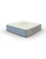
- User Manual
- ALL RIGHTS RESERVED.
- About this Manual
- Trademarks Acknowledgement
- Legal Disclaimer
- Regulatory Informaon
- FCC Informaon
- FCC Conditions
- EU Conformity Statement
- Industry Canada ICES-003 Compliance
- Applicable Models
- Symbol Conventions
- Safety Instructions
- Preventive and Cautionary Tips
- Product Key Features
- General
- NOTE
- Local Monitoring
- HDD Management
- Recording, Capture and Playback
- Backup
- Alarm and Excepon
- Other Local Funcons
- Network Funcons
- Development Scalability
- Table of Contents
- Chapter 4 PTZ Controls ....88
- Chapter 5 Recording and Capture Settings....100
- Chapter 6 Playback....127
- Chapter 1 Introduction
- Front Panel
- Front Panel 4:
- IR Remote Control Operations
- USB Mouse Operation
- Input Method Description
- Rear Panel
- Rear Panel 6:
- i NOTE
- Rear Panel 9:
- Rear Panel 10:
- Rear Panel 11:
- Chapter 2 Getting Started
- Starting Up and Shutting Down the DVR
- Purpose
- Before you start
- Starng up the DVR
- Shung down the DVR
- • OPTION 1: Standard shutdown
- Reboong the DVR
- Activating the Device
- WARNING
- Using the Unlock Pattern for Login
- Configuring the Unlock Pattern
- Logging in via Unlock Pattern
- Basic Configuration in Startup Wizard
- Configuring the Signal Input Wizard
- Using the Wizard for Basic Configuration
- Selecng the language:
- Operang the Setup Wizard:
- Login and Logout
- User Login
- User Logout
- Adding and Connecting the IP Cameras
- Activating the IP Camera
- Adding the Online IP Camera
- - OPTION 1:
- - OPTION 2:
- Editing the Connected IP Camera
- Configuring the Signal Input Channel
- Chapter 3 Live View
- Introduction of Live View
- Live View Icons
- Operations in Live View Mode
- Using the Mouse in Live View
- Switching Main/Aux Output
- Quick Setting Toolbar in Live View Mode
- Channel-Zero Encoding
- Adjusting Live View Settings
- Manual Video Quality Diagnostics
- Chapter 4 PTZ Controls
- Configuring PTZ Settings
- Setting PTZ Presets, Patrols and Patterns
- Customizing Presets
- Calling Presets
- Customizing Patrols
- Calling Patrols
- Customizing Patterns
- Calling Patterns
- Customizing Linear Scan Limit
- Calling Linear Scan
- One-touch Park
- PTZ Control Panel
- OPTION 1:
- OPTION 2:
- Chapter 5 Recording and Capture Settings
- Configuring Encoding Parameters
- Steps
- Configuring Recording and Capture Schedule
- Edit the schedule
- Draw the schedule
- Configuring Motion Detection Recording and Capture
- Step 2 Congure Moon Detecon:
- Configuring Alarm Triggered Recording and Capture
- Configuring Event Recording and Capture
- Configuring Manual Recording and Continuous Capture
- Configuring Holiday Recording and Capture
- Configuring Redundant Recording and Capture
- Configuring HDD Group
- Files Protection
- Protect le by locking the record les
- Protect le by seng HDD property to Read-only
- One-Key Enabling and Disabling H.264+ for Analog Cameras
- Task 1: One-Key Enabling H.264+ for All Analog Cameras
- Task 2: One-Key Disabling H.264+ for All Analog Cameras
- Configuring 1080P Lite
- Task2: Disabling the 1080P Lite Mode
- Chapter 6 Playback
- Playing Back Record Files
- Instant Playback
- Instant playback by channel
- Playing Back by Normal Search
- Playback Interface
- Playing Back by Event Search
- Playing Back by Tag
- Before playing back by tag
- Playing Back by Smart Search
- ● Line Crossing Detecon
- - Intrusion Detecon
- - Moon Detecon
- Playing Back by System Logs
- Playing Back by Sub-Periods
- Playing Back External File
- Playing Back Pictures
- Auxiliary Functions of Playback
- Playing Back Frame by Frame
- Digital Zoom
- Reverse Playback of Multi-Channel
- Chapter 7 Backup
- Backing up Record Files
- Backing up by Normal Video/Picture Search
- Backup using USB ash drives and USB HDDs
- Backing up by Event Search
- Backing up Video Clips
- Managing Backup Devices
- Chapter 8 Alarm Settings
- Setting Motion Detection
- Setting Sensor Alarms
- Detecting Video Loss
- Detecting Video Tampering
- Setting All-day Video Quality Diagnostics
- Handling Exceptions
- Setting Alarm Response Actions
- Full Screen Monitoring
- Audible Warning
- Nofy Surveillance Center
- Send Email
- Trigger Alarm Output
- Chapter 9 POS Configuration
- Configuring POS Settings
- ● Universal Protocol
- - NUCLEUS
- - TCP Connecon
- - UDP Connecon
- - USB->RS-232 Connecon
- - RS-232 Connecon
- - Mulcast Connecon
- - Sni Connecon
- Configuring Overlay Channel
- Configuring POS Alarm
- Chapter 10 VCA Alarm
- Face Detection
- Vehicle Detection
- Line Crossing Detection
- Intrusion Detection
- Region Entrance Detection
- Region Exiting Detection
- Loitering Detection
- People Gathering Detection
- Fast Moving Detection
- Parking Detection
- Unattended Baggage Detection
- Object Removal Detection
- Audio Exception Detection
- Defocus Detection
- Sudden Scene Change
- PIR Alarm
- Chapter 11 VCA Search
- Face Search
- Behavior Search
- Plate Search
- People Counting
- Heat Map
- Chapter 12 Network Settings
- Configuring General Settings
- Working Mode
- Configuring Advanced Settings
- Configuring PPPoE Settings
- Configuring Hik Cloud P2P
- Configuring DDNS
- - DynDNS:
- ● OPTION 2: Access the devices via iVMS-4200
- Configuring NTP Server
- Configuring NAT
- OPTION 1: Auto
- OPTION 2: Manual
- Configuring More Settings
- Configuring HTTPS Port
- Example
- OPTION 1: Create the self-signed cercate
- OPTION 2: Create the authorized cercate
- Configuring Email
- Checking Network Traffic
- Configuring Network Detection
- Testing Network Delay and Packet Loss
- Exporting Network Packet
- Checking Network Status
- Checking Network Statistics
- Purpose:
- Chapter 13 RAID
- Configuring Array
- Introducon
- Enable RAID
- One-touch Configuration
- Manually Creating Array
- Rebuilding Array
- Automatically Rebuilding Array
- Manually Rebuilding Array
- Deleting Array
- Checking and Editing Firmware
- Chapter 14 HDD Management
- Initializing HDDs
- Managing Network HDD
- - Add NAS disk:
- - Add IP SAN:
- Managing HDD Group
- Setting HDD Groups
- Setting HDD Property
- Configuring Quota Mode
- Configuring Cloud Storage
- Configuring Disk Clone
- Checking HDD Status
- Checking HDD Status in HDD Informaon Interface
- Checking HDD Status in System Informaon Interface
- Checking S.M.A.R.T Information
- Detecting Bad Sector
- Configuring HDD Error Alarms
- Chapter 15 Camera Settings
- Configuring OSD Settings
- Configuring Privacy Mask
- Configuring Video Parameters
- Configuring Image Settings
- Configuring Camera Parameters Settings
- Chapter 16 DVR Management and Maintenance
- Viewing System Information
- Searching Log Files
- Importing/Exporting IP Camera Info
- Importing/Exporting Configuration Files
- Upgrading System
- Upgrading by Local Backup Device
- Upgrading by FTP
- Restoring Default Settings
- Chapter 17 Others
- Configuring General Settings
- Configuring RS-232 Serial Port
- Configuring DST Settings
- Configuring More Settings
- Managing User Accounts
- Adding a User
- Local Conguraon
- Remote Conguraon
- Camera Conguraon
- Deleting a User
- Editing a User
- - Operator and Guest
- - Admin
- Chapter 18 Appendix
- Specifications
- Glossary
- Troubleshooting
- Possible Reasons:
- Summary of Changes
- Updated:
- Deleted:
- First Choice for Security Professionals
Brand : Hikvision
Model : DS-7616HUHI-F2/N
Category : Dictaphone