WKS 180 E - Grinder BTI - Free user manual and instructions
Find the device manual for free WKS 180 E BTI in PDF.


| Product Type | Angle Grinder |
| Model | WKS 180 E |
| Brand | BTI |
| Rated Power | 2400 W |
| Output Power | 1600 W |
| No-Load Speed | 8500 rpm |
| Grinding Disc Diameter (max) | 180 mm |
| Spindle Thread | M 14 |
| Weight (without cable) | 5.3 kg |
| Protection Class | II (Double Insulated) |
| Reduced Starting Current | Yes (13 A fuse adequate) |
| Run-On Brake | Not on this model (available on WKS 230 SE) |
| Sound Pressure Level | 93 dB(A) |
| Sound Power Level | 106 dB(A) |
| Vibration Level (typical) | 5.2 m/s² |
| Intended Use | Cutting, roughing, and brushing metal and stone (dry) |
| Protective Devices | Protection guard, auxiliary handle, hand guard (optional) |
| Accessories Included | Protection guard, auxiliary handle, quick-clamping nut, mounting flange |
| Optional Accessories | Cutting guide, dust extraction guard, rubber sanding pad, cup brush, diamond cutting disc, grinder stand |
| Handle Adjustment | Rotatable 90° left/right with safety interlock |
| Maintenance | Keep ventilation slots clean; blow out dust; use RCD in extreme conditions |
| Safety Features | Spindle lock, lock-on switch, reduced starting current, safety guard, hand guard |
Frequently Asked Questions - WKS 180 E BTI
User questions about WKS 180 E BTI
0 question about this device. Answer the ones you know or ask your own.
Ask a new question about this device
Download the instructions for your Grinder in PDF format for free! Find your manual WKS 180 E - BTI and take your electronic device back in hand. On this page are published all the documents necessary for the use of your device. WKS 180 E by BTI.
USER MANUAL WKS 180 E BTI

| >100% |
Gerätekennwerte
Winkelschleifer BTI-WKS 180 E BTI-WKS 230 E BTI-WKS 230 SE
Zu Ihrer Sicherheit
Para su seguridad
| Order number 015861 016312 015862 | ||||
| Rated power [W] 2 400 2 400 2 400 | ||||
| Output power [W] 1 600 1 600 1 600 | ||||
| No-load speed | [rpm] | 8 500 | 6 500 | 6 500 |
| Grinding disc dia. | [mm] | max. 180 | max. 230 | max. 230 |
| Reduced starting current | • | • | • | |
| Run-on brake | - | - | • | |
| Grinder spindle thread | M 14 | M 14 | M 14 | |
| Weight without cable, approx. | [kg] | 5.3 | 5.3 | 5.3 |
| Protection class | ☐ / II | ☐ / II | ☐ / II | |
Inrush currents cause short-time voltage drops. Under unfavourable power supply conditions, other equipment may be affected. If the system impedance of the power supply is lower than 0.25 Ohm, disturbances are unlikely to occur.
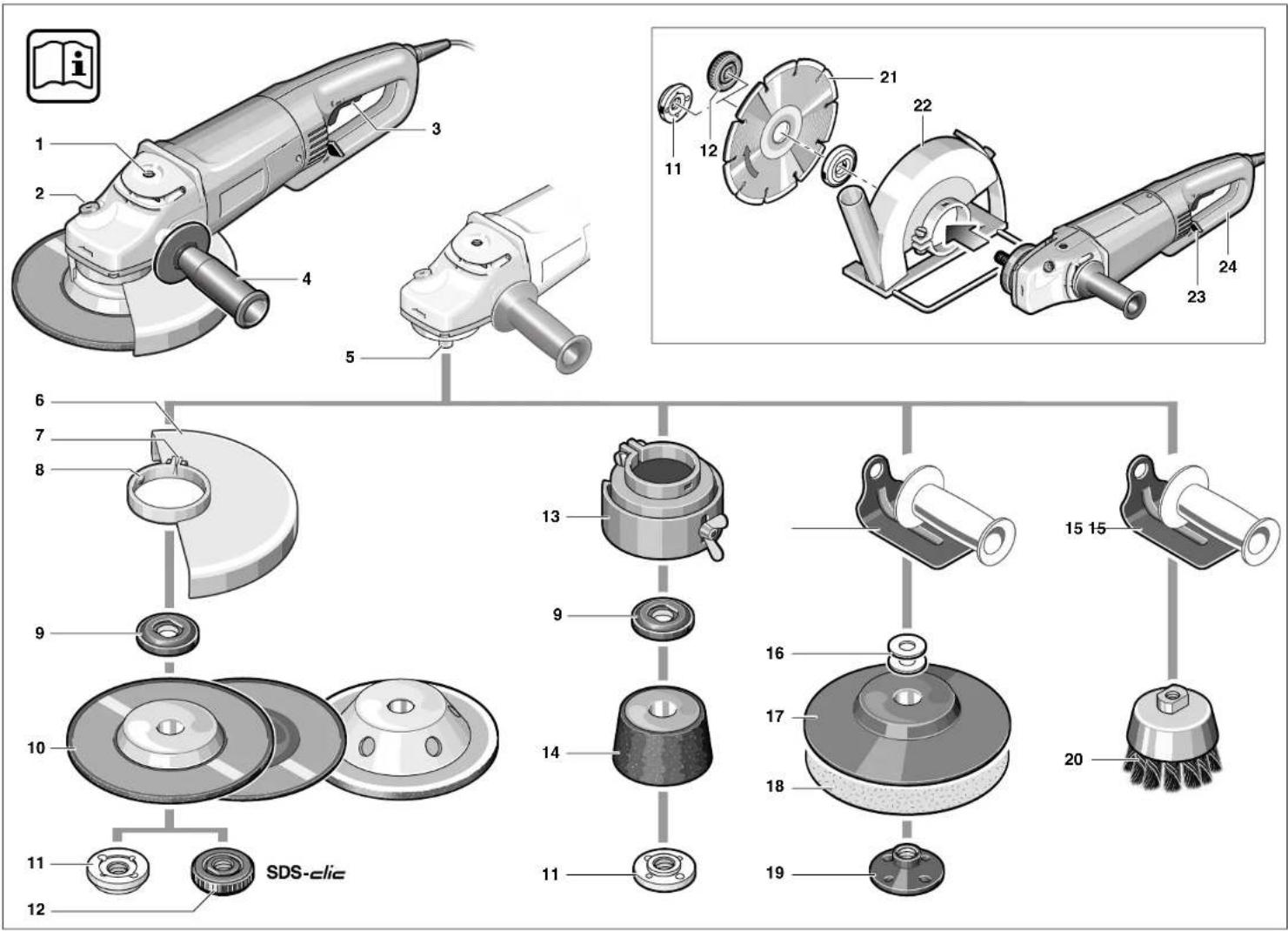
Machine Elements
1 Thread for auxiliary handle (3x)
2 Spindle lock button
3 On/Off switch
4 Auxiliary handle
5 Grinder spindle
6 Protection guard
7 Clamping screw
8 Coded projection
9 Mounting flange
10 Grinding/cutting disc*
11 Clamping nut*
12 quick-clamping nut*
13 Guard, grinding cup*
14 Grinding cup*
15 Hand guard*
16 Spacers*
17 Rubber sanding pad*
18 Sanding disc*
19 Round nut*
20 Cup brush*
21 Diamond cutting disc*
22 Cutting guide with dust extraction protection guard*
23 Handle unlocking button
24 Handle
* Not all of the accessories illustrated or described are included as standard delivery.
Noise/Vibration Information
Measured values determined according to EN 50 144.
Typically the A-weighted noise levels of the product are: sound pressure level: 93 dB (A); sound power level: 106 dB (A).
Wear hearing protection!
The typically weighted acceleration is 5.2 m/s 4 .
Intended Use
The machine is intended for cutting, roughing and brushing metal and stone materials without using water. For cutting stone, a cutting guide is required.
Information on Structures
Slots in structural walls are subject to the Standard DIN 1053, Part 1 or country-specific regulations.
These regulations are to be observed under all circumstances. Before beginning work, consult the responsible structural engineer, architects or the construction supervisor.

For Your Safety
Working safely with this machine is possible only when the operating and safety information are read completely and the instructions contained therein are strictly followed. Before using for the first time, ask for a practical demonstration.
■Wear protective glasses and hearing protection.
■Wear additional protection equipment for your safety, such as protective gloves, sturdy shoes, hard hat and apron.
■The dust that is produced while working can be detrimental to health, inflammable or explosive. Suitable safety measures are required. Examples: Some dusts are regarded as carcinogenic. Use suitable dust/chip extraction and wear a dust respirator.
■Dust from light alloys can burn or explode. Always keep the workplace clean, as blends of materials are particularly dangerous.
If the mains cable is damaged or cut through while working, do not touch the cable but immediately pull the mains plug. Never use the machine with a damaged cable.
■Connect machines that are used in the open via a residual current device (RCD) with an actuating current of 30 mA maximum. Use only extension cables that are approved for outdoor use.
■When working with the machine, always hold it firmly with both hands and provide for a secure stance.
■Secure the workpiece. A workpiece clamped with clamping devices or in a vice is held more secure than by hand.
■Always direct the cable to the rear away from the machine.
■Always switch the machine off and wait until it has come to a standstill before placing it down.
■For power outage or when the mains plug is pulled, unlock the On/Off switch immediately and turn it to the off position. This prevents uncontrolled restarting.
■The machine must be used only for dry cutting/grinding.
■For all work with the machine, the auxiliary handle 4 must be mounted.
■Hold the power tool only by the insulated gripping surfaces, when performing an operation where the cutting tool may run into hidden wiring or its own cord.
Contact with a "live" wire will make exposed metal parts of the tool "live" and shock the operator.
■Use appropriate detectors to determine if utility lines are hidden in the work area or call the local utility company for assistance.
Contact with electric lines can lead to fire and electric shock. Damaging a gas line can lead to explosion. Penetrating a water line causes property damage or may cause an electric shock.
■For work with grinding or cutting discs, the protection guard 6 must be mounted. For work with the rubber sanding pad 17 or with the cup brush 20/disc brush/flap disc, mounting the hand protector 15 (accessory) is recommended.
■Use dust extraction when working with stone. The vacuum cleaner must be approved for masonry dust. When cutting stone, use the cutting guide.
■Do not work with materials containing asbestos.
■Use only grinding tools with a permissible speed at least as high as the no-load speed of the machine.
■Check grinding tools before use. The grinding tool must be properly mounted and turn freely. Perform a test run for at least 30 seconds without load. Do not use damaged, out-of-round or vibrating grinding tools.
■Protect the grinding tool from impact, shock and grease.
■Apply the machine to the workpiece only when switched on.
■Keep hands away from rotating grinding tools.
■Pay attention to the direction of rotation. Always hold the machine so that sparks and grinding dust fly away from the body.
■When grinding metal, flying sparks are produced. Take care that no persons are endangered. Due to danger of fire, no combustible materials should be located in the vicinity (spark flight zone).
■Be careful when cutting grooves, e. g. in structural walls: See Information on Structures.
■Blocking the cutting disc leads to jerking reaction forces on the machine. In this case switch off the machine immediately.
■Pay attention to the dimensions of the grinding disc. The mounting hole diameter must fit the mounting flange 9 without play. Do not use reducer pieces or adapters.
■Never use cutting discs for rough grinding. Do not exert any lateral pressure on the cutting discs.
- Observe the manufacturer's instructions for mounting and using grinding tools.
■Caution! The grinding tool runs on after the machine is switched off.
■Do not clamp the machine in a vice.
■Never allow children to use the machine.
■BTI is only able to ensure perfect operation of the machine if the original accessories intended for it are used.

Mounting the Protective Devices
■Before any work on the machine itself, pull the mains plug.
■For work with grinding or cutting discs, the protection guard 6 must be mounted.
Protection Guard with Locking Screw
The coded projection 8 on the protection guard 6 ensures that only a guard that fits the machine type can be mounted.
Loosen the clamping screw 7, if necessary.
Place the protection guard 6 with coded projection 8 into the coded groove on the spindle collar of the machine head and rotate to the required position (working position).
The closed side of the protection guard 6 must always point to the operator.
Tighten clamping screw 7.
Auxiliary Handle
■For all work with the machine, the auxiliary handle 4 must be mounted.
Screw the auxiliary handle 4 into the head of the machine according to the working method.

Do not make any alterations to the auxiliary handle.
Do not continue to use an auxiliary handle if it is damaged.
Hand Guard
For work with the rubber sanding pad 17 or with the cup brush 20/disc brush/flap disc, mounting the hand protector 15 (accessory) is recommended. The hand protector 15 is fastened with the auxiliary handle 4.
Mounting the Grinding Tools
■Before any work on the machine itself, pull the mains plug.

Use only grinding tools with a permissible speed at least as high as the no-load speed of the machine.
Grinding and cutting discs become very hot while working; do not touch until they have cooled.
It is recommended to use the quick-clamping nut 12. When using the clamping nut 11 increased effort to loosen the clamping nut must be taken into account.
■Clean the grinder spindle and all parts to be mounted. For clamping and loosening the grinding tools, lock the grinder spindle 5 with the spindle lock button 2.
Actuate the spindle lock button 2 only when the grinder spindle is at a standstill!
Quick Clamping Nut SDS-clic
When using the quick-clamping nut 12, grinding tools can be mounted without additional tools.
Use only a flawless, undamaged quick-clamping nut 12.
When screwing on, take care that the side with printing does not point to the grinding disc. The arrow must point to the index mark 25.
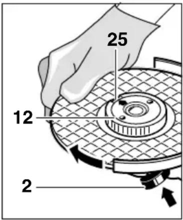
Lock the grinder spindle with the spindle lock button 2. Tighten the quick-clamping nut by forcefully turning the grinding disc in the clockwise direction.
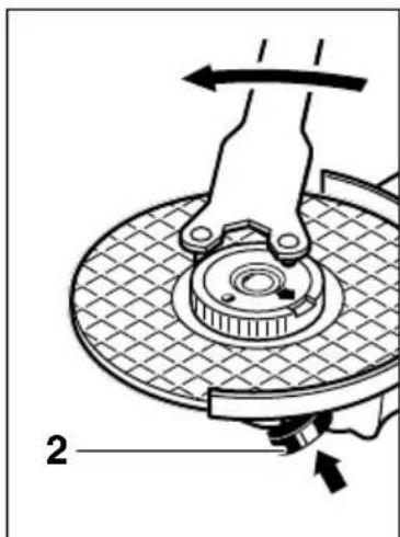
A properly tightened undamaged, quick-clamping nut can be loosened by hand turning the knurled ring in the counterclockwise direction.
Never loosen a tight quick-clamping nut with pliers but use a two-pin spanner. Insert the two-hole spanner as shown in the illustration.
Grinding/Cutting Disc
■Pay attention to the dimensions of the grinding disc. The mounting hole diameter must fit the mounting flange 9 without play. Do not use reducer pieces or adapters.
When using a diamond cutting disc, take care that the direction-of-rotation arrow on the diamond cutting disc and the direction of rotation of the machine (direction-of-rotation arrow on the machine head) agree.
For mounting, see the illustration page.
Position the grinding/cutting disc onto the mounting flange 9. Ensure that the grinding tool is seated centred and without play on the mounting flange.
Screw on the quick-clamping nut 12 and tighten the grinding disc.
■After mounting the grinding tool and before switching on, check that the grinding tool is correctly mounted and that it can turn freely.
Flap Disc
Depending on the application, remove the protection guard 6 and mount the hand guard 15.
Position the flap disc on the grinder spindle 5. Screw on the quick-clamping nut 12 and tighten the flap disc.
Rubber Sanding Pad 17
Depending on the application, remove the protection guard 6 and mount the hand guard 15.
Before mounting the rubber sanding pad 17, place the 2 spacers 16 onto the grinding spindle.
For mounting, see the illustration page.
Screw on the round nut 19 and tighten with the two-pin spanner.
Increased effort must be taken into account when loosening the round nut 19.
Cup Brush 20/Disc Brush
Depending on the application, remove the protection guard 6 and mount the hand guard 15.
The grinding tool must be able to be screwed onto the grinding spindle 5 until it rests firmly against the grinder spindle flange at the end of the grinder spindle threads. Tighten with an open-end spanner.
Increased effort must be taken into account when loosening the grinding tool.
Grinding Cup
When working with grinding cups, use the special guard 13.
The grinding cup 14 should always protrude from the guard 13 only as far as absolutely necessary for the work to be performed in each case.
Adjust the guard 13 to this distance.
For mounting, see the illustration page.
Screw on the clamping nut 11 and tighten with the fitting offset two-pin spanne.
Increased effort must be taken into account when loosening the clamping nut 11.
Approved Grinding Tools
All grinding tools mentioned in this operating manual instruction can be used.
The permissible speed [rpm] or the circumferential speed [m/s] of the grinding tools used must at least match the values given in the table.
Therefore, always observe the permissible rotational/circumferential speed on the label of the grinding tool.
| max.[mm] [mm] | d | [rpm] [m/s] | |||
| D | b | ||||
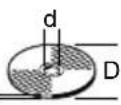 b: b: | 180 | 8 | 22.2 | 8 500 | 80 |
| 230 | 8 | 22.2 | 6 500 | 80 | |
—D— 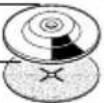 | 180 | - | - | 8 500 | 80 |
| 230 | - | - | 6 500 | 80 | |
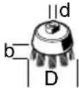 | 100 | 30 M | 14 8 500 | 45 | |
Initial Operation Operating Instructions
Observe correct mains voltage: The voltage of the power source must agree with the voltage specified on the nameplate of the machine. Equipment marked with 230 V can also be connected to 220 V.
Switching On and Off
To start the machine, press the On/Off switch 3 forward and then down.
To lock-on, push the pressed On/Off switch 3 further forwards.
To switch off the machine, release the On/Off switch 3 or push and release it then.
Switch version without lock (country-specific):
To start the machine, press the On/Off switch 3 forward and then down.
To switch off the machine, release the On/Off switch 3.
■Test run!
Check the grinding tool before use. The grinding tool must be properly mounted and rotate freely. Perform a test run of at least 30 seconds without load. Do not use damaged, out-of-round or vibrating grinding tools.
Run-on Brake (BTI-WKS 230 SE)

This machine is equipped with the BTI Brake System.
When switching off or in case of a power supply interruption, the grinding tool is stopped within a few seconds. This means the run-on time is reduced by approx. 70 % in comparison to angle grinders without run-on brake, and that the machine can be placed down in shorter time.
Should the braking effect of the run-on brake noticeably diminish, have the machine checked by an after-sales service centre for BTI power tools.
Reduced Starting Current
As a result of soft starting, a 13 A fuse is adequate.
■Clamp the workpiece if it does not remain stationary due to its own weight.
■Do not strain the machine so heavily that it comes to a standstill.
■Grinding and cutting discs become very hot while working; do not touch until they have cooled.
Rough Grinding

The best roughing results are achieved when setting the machine at an angle of 30° to 40° . Move the machine back and forth with moderate pressure. In this manner, the workpiece will not become too hot, does not discolour and no grooves are formed.

Never use a cutting disc for roughing.
Flap Disc
With the flap disc (accessory), curved surfaces and profiles (contour sanding) can be worked.
Flap discs have a considerably higher service life than sanding sheets, lower noise level and lower sanding temperatures.
Cutting
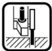
When cutting, do not press, jam or oscillate the machine. Work with moderate feed, adapted to the material being machined.
Do not reduce the speed of running down cutting discs by applying sideward pressure.
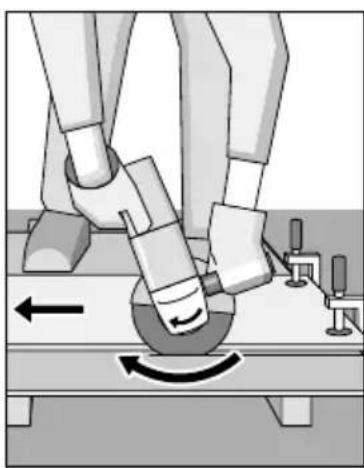
The direction in which the cutting is performed is important.
The machine must always work in an up-grinding motion. Therefore, never move the machine in the other direction! Otherwise, the danger exists of it being pushed uncontrolled out of the cut.
Grinder Stand
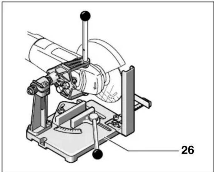
With the grinder stand 26 (accessory), workpieces can be cut at angles of 0 to 45° at the same lengths.
The safety notes and operating instructions in the respective operating instructions manual of the angle grinder are to be strictly observed. Use only original BTI grinder stands.
Cutting Stone
■The machine must be used only for dry cutting/grinding.
It is best to use a diamond cutting disc. As a safety measure against jamming, use the cutting guide 22 with the special dust extraction protection guard.
Operate the machine with dust extraction only. In addition, wear a dust mask.
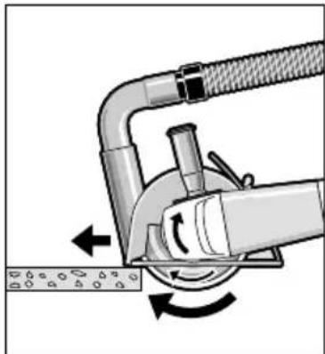
The vacuum cleaner must be approved for the extraction of masonry dust.
BTI provides suitable vacuum cleaners.
Switch on the machine and place the front part of the cutting guide on the workpiece.
Slide the machine with moderate feed, adapted to the material to be worked (Figure).
For cutting especially hard material, e. g., concrete with high pebble content, the diamond cutting disc can overheat and become damaged as a result. This is clearly indicated by circular sparking, rotating with the diamond cutting disc.
In this case, interrupt the cutting process and allow the diamond cutting disc to cool by running freely at no-load speed for a short time.
Noticeable decreasing work progress and circular sparking are indications of a diamond cutting disc that has become dull. Briefly cutting into abrasive material (e. g., lime-sand brick) can re-sharpen the disc.
Turning the Machine Handle
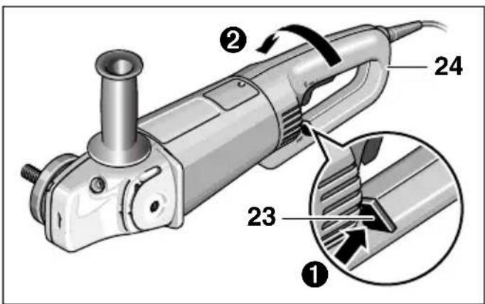
The handle 24 can be turned with respect to the motor housing by 90° either to the left or right. This allows for the On/Off switch to be positioned more conveniently for certain working situations, e. g., for cutting work with the cutting guide/grinder stand (accessories) and for left-handers.
Pull the handle unlocking button 23 firmly in the direction of the arrow (①), turning the handle 24 at the same time to the desired position (②) until it engages. The figure shows the handle 24 turned by 90°.
■ The handle unlocking button 23 and the On/Off switch 3 have a safety interlock.
The machine cannot be switched on if the handle 24 is not engaged in one of the three possible positions.
The handle 24 cannot be unlocked if the On/Off switch 3 is locked.
Maintenance and Cleaning
■Before any work on the machine itself, pull the mains plug.
■For safe and proper working, always keep the machine and the ventilation slots clean.

In extreme working conditions, conductive dust can accumulate in the interior of the machine when working with metal. The protective insulation of the machine can be degraded. The use of a stationary extraction system is recommended in such cases as well as frequently blowing out the ventilation slots and installing a residual current device (RCD).
If the machine should fail despite the care taken in manufacturing and testing procedures, repair should be carried out by an after-sales service centre for BTI power tools.
In all correspondence and spare parts orders, please always include the 6-digit order number given on the nameplate of the machine.
WARNING! Important instructions for connecting a new 3-pin plug to the 2-wire cable.
The wires in the cable are coloured according to the following code:

Do not connect the blue or brown wire to the earth terminal of the plug.
Important: If for any reason the moulded plug is removed from the cable of this machine, it must be disposed of safely.
Environmental Protection

Recycle raw materials instead of disposing as waste
The machine, accessories and packaging should be sorted for environmental-friendly recycling.
These instructions are printed on recycled paper manufactured without chlorine.
The plastic components are labelled for categorized recycling.
Service
CE Declaration of Conformity
We declare under our sole responsibility that this product is in conformity with the following standards or standardization documents: EN 50 144 according to the provisions of the directives 89/336/EEC, 98/37/EC.
ppa. U. Delz i.V. G. Hub
Subject to change without notice
General Safety Rules
WARNING! Read all instructions. Failure to follow all instructions listed below may result in electric shock, fire and/or serious injury. The term “power tool” in all of the warnings listed below refers to your mains operated (corded) power tool or battery operated (cordless) power tool.
SAVE THESE INSTRUCTIONS.
1) Work area
a) Keep work area clean and well lit. Cluttered and dark areas invite accidents.
b) Do not operate power tools in explosive atmospheres, such as in the presence of flammable liquids, gases or dust. Power tools create sparks which may ignite the dust or fumes.
c) Keep children and bystanders away while operating a power tool. Distractions can cause you to lose control.
2) Electrical safety
a) Power tool plugs must match the outlet. Never modify the plug in any way. Do not use any adapter plugs with earthed (grounded) power tools. Unmodified plugs and matching outlets will reduce risk of electric shock.
b) Avoid body contact with earthed or grounded surfaces such as pipes, radiators, ranges and refrigerators. There is an increased risk of electric shock if your body is earthed or grounded.
c) Do not expose power tools to rain or wet conditions. Water entering a power tool will increase the risk of electric shock.
d) Do not abuse the cord. Never use the cord for carrying, pulling or unplugging the power tool. Keep cord away from heat, oil, sharp edges or moving parts. Damaged or entangled cords increase the risk of electric shock.
e) When operating a power tool outdoors, use an extension cord suitable for outdoor use. Use of a cord suitable for outdoor use reduces the risk of electric shock.
3) Personal safety
a) Stay alert, watch what you are doing and use common sense when operating a power tool. Do not use a power tool while you are tired or under the influence of drugs, alcohol or medication. A moment of inattention while operating power tools may result in serious personal injury.
b) Use safety equipment. Always wear eye protection. Safety equipment such as dust mask, nonskid safety shoes, hard hat, or hearing protection used for appropriate conditions will reduce personal injuries.
c) Avoid accidental starting. Ensure the switch is in the off position before plugging in. Carrying power tools with your finger on the switch or plugging in power tools that have the switch on invites accidents.
d) Remove any adjusting key or wrench before turning the power tool on. A wrench or a key left attached to a rotating part of the power tool may result in personal injury.
e) Do not overreach. Keep proper footing and balance at all times. This enables better control of the power tool in unexpected situations.
f) Dress properly. Do not wear loose clothing or jewellery. Keep your hair, clothing and gloves away from moving parts. Loose clothes, jewellery or long hair can be caught in moving parts.
g) If devices are provided for the connection of dust extraction and collection facilities, ensure these are connected and properly used. Use of these devices can reduce dust related hazards.
4) Power tool use and care
a) Do not force the power tool. Use the correct power tool for your application. The correct power tool will do the job better and safer at the rate for which it was designed.
b) Do not use the power tool if the switch does not turn it on and off. Any power tool that cannot be controlled with the switch is dangerous and must be repaired.
c) Disconnect the plug from the power source before making any adjustments, changing accessories, or storing power tools. Such preventive safety measures reduce the risk of starting the power tool accidentally.
d) Store idle power tools out of the reach of children and do not allow persons unfamiliar with the power tool or these instructions to operate the power tool. Power tools are dangerous in the hands of untrained users.
e) Maintain power tools. Check for misalignment or binding of moving parts, breakage of parts and any other condition that may affect the power tools operation. If damaged, have the power tool repaired before use. Many accidents are caused by poorly maintained power tools.
f) Keep cutting tools sharp and clean. Properly maintained cutting tools with sharp cutting edges are less likely to bind and are easier to control.
g) Use the power tool, accessories and tool bits etc., in accordance with these instructions and in the manner intended for the particular type of power tool, taking into account the working conditions and the work to be performed. Use of the power tool for operations different from those intended could result in a hazardous situation.
5) Battery tool use and care
a) Ensure the switch is in the off position before inserting battery pack. Inserting the battery pack into power tools that have the switch on invites accidents.
b) Recharge only with the charger specified by the manufacturer. A charger that is suitable for one type of battery pack may create a risk of fire when used with another battery pack.
c) Use power tools only with specifically designated battery packs. Use of any other battery packs may create a risk of injury and fire.
d) When battery pack is not in use, keep it away from other metal objects like paper clips, coins, keys, nails, screws, or other small metal objects that can make a connection from one terminal to another. Shorting the battery terminals together may cause burns or a fire.
e) Under abusive conditions, liquid may be ejected from the battery; avoid contact. If contact accidentally occurs, flush with water. If liquid contacts eyes, additionally seek medical help. Liquid ejected from the battery may cause irritation or burns.
6) Service
a) Have your power tool serviced by a qualified repair person using only identical replacement parts. This will ensure that the safety of the power tool is maintained.
BTI Zentrale

- GERÄTEKENNWERTE
- ZU IHRER SICHERHEIT
- PARA SU SEGURIDAD
- MACHINE ELEMENTS
- NOISE/VIBRATION INFORMATION
- WEAR HEARING PROTECTION
- INTENDED USE
- INFORMATION ON STRUCTURES
- FOR YOUR SAFETY
- MOUNTING THE PROTECTIVE DEVICES
- PROTECTION GUARD WITH LOCKING SCREW
- AUXILIARY HANDLE
- HAND GUARD
- MOUNTING THE GRINDING TOOLS
- QUICK CLAMPING NUT SDS-CLIC
- GRINDING/CUTTING DISC
- FOR MOUNTING, SEE THE ILLUSTRATION PAGE
- FLAP DISC
- RUBBER SANDING PAD 17
- CUP BRUSH 20/DISC BRUSH
- GRINDING CUP
- APPROVED GRINDING TOOLS
- INITIAL OPERATION OPERATING INSTRUCTIONS
- SWITCHING ON AND OFF
- SWITCH VERSION WITHOUT LOCK (COUNTRY-SPECIFIC)
- TEST RUN
- RUN-ON BRAKE (BTI-WKS 230 SE)
- REDUCED STARTING CURRENT
- ROUGH GRINDING
- CUTTING
- GRINDER STAND
- CUTTING STONE
- MAINTENANCE AND CLEANING
- WARNING! IMPORTANT INSTRUCTIONS FOR CONNECTING A NEW 3-PIN PLUG TO THE 2-WIRE CABLE
- ENVIRONMENTAL PROTECTION
- RECYCLE RAW MATERIALS INSTEAD OF DISPOSING AS WASTE
- SERVICE
- CE DECLARATION OF CONFORMITY
- GENERAL SAFETY RULES
- WORK AREA
- ELECTRICAL SAFETY
- PERSONAL SAFETY
- POWER TOOL USE AND CARE
- BATTERY TOOL USE AND CARE
- BTI ZENTRALE
Brand : BTI
Model : WKS 180 E
Category : Grinder