
DM12-1005-1 - Uncategorized Ergotron - Free user manual and instructions
Find the device manual for free DM12-1005-1 Ergotron in PDF.


User questions about DM12-1005-1 Ergotron
0 question about this device. Answer the ones you know or ask your own.
Ask a new question about this device
Download the instructions for your Uncategorized in PDF format for free! Find your manual DM12-1005-1 - Ergotron and take your electronic device back in hand. On this page are published all the documents necessary for the use of your device. DM12-1005-1 by Ergotron.
USER MANUAL DM12-1005-1 Ergotron
Tablet Charging Wall Mount 12
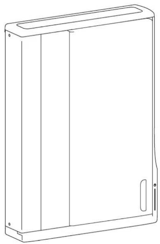
natural_image
Line drawing of a rectangular electronic device casing with mounting holes and a side panel (no text or symbols)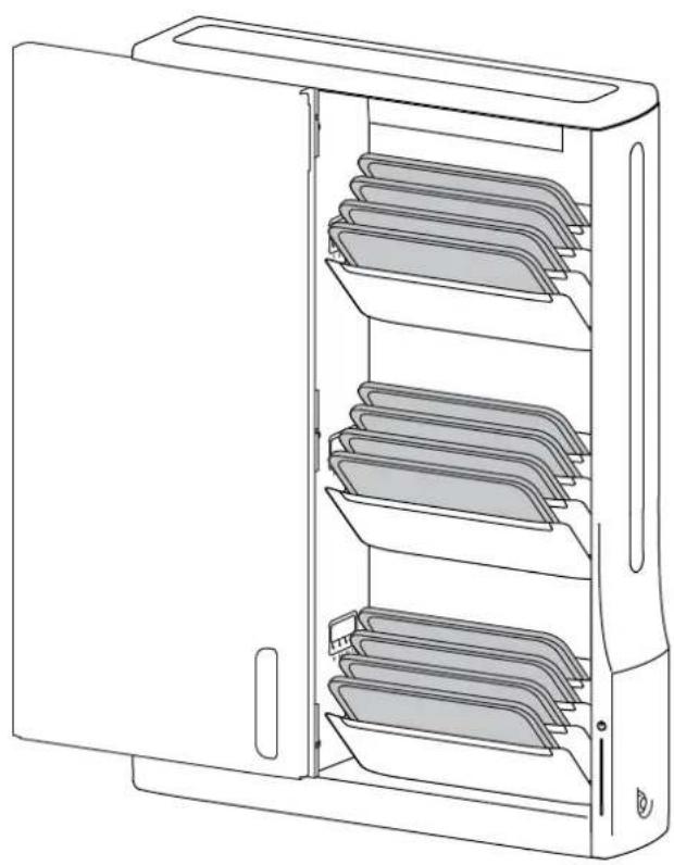
natural_image
Line drawing of a computer tower cabinet with multiple storage compartments (no text or symbols)For the latest User Installation Guide please visit: www.ergotron.com

User's Guide - English
Hazard Symbols Review
These symbols alert users of a safety condition that demands attention. All users should be able to recognize and understand the significance of the following Safety Hazards if encountered on the product or within the documentation. Children who are not able to recognize and respond appropriately to Safety Alerts should not use this product without adult supervision!
Symbol Signal Word Level of Hazard
 | NOTE | A NOTE indicates important information that helps you make better use of this product. |
 | CAUTION | A CAUTION indicates either potential damage to hardware or loss of data and tells you how to avoid the problem. |
 | WARNING | A WARNING indicates either potential for property damage, personal injury, or death. |
 | ELECTRICAL | An Electrical indicates an impending electrical hazard which, if not avoided, may result in personal injury, fire and/or death. |
Safety

WARNING: Because surfaces vary widely and the ultimate mounting method is out of Ergotron's control, it is imperative that you consult with appropriate engineering, architectural or construction professional to ensure that your Ergotron mounting solution is mounted properly to handle applied loads.

CAUTION: Make sure the wall mount bracket is level, fl ush and snug to the wall surface. DO NOT OVER-TIGHTEN THE BOLTS.

≤ 44.4 lbs. (20.1 kg)
CAUTION: DO NOT EXCEED MAXIMUM LISTED WEIGHT CAPACITY. SERIOUS INJURY OR PROPERTY DAMAGE MAY OCCUR!
Components

natural_image
Pure technical line drawing of a mechanical part with holes and flanges (no text or symbols)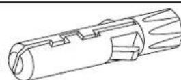
Tools Needed
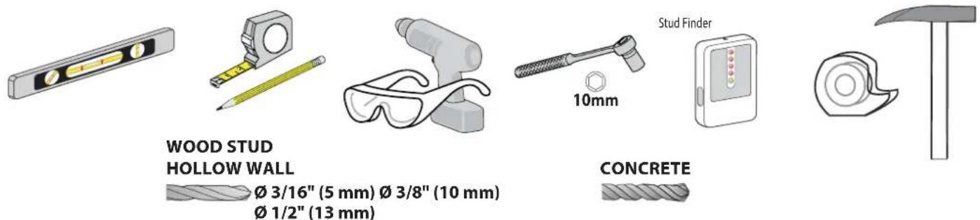
text_image
WOOD STUD HOLLOW WALL Ø 3/16" (5 mm) Ø 3/8" (10 mm) Ø 1/2" (13 mm) Stud Finder 10mm CONCRETE1 MOUNTING CONSIDERATIONS
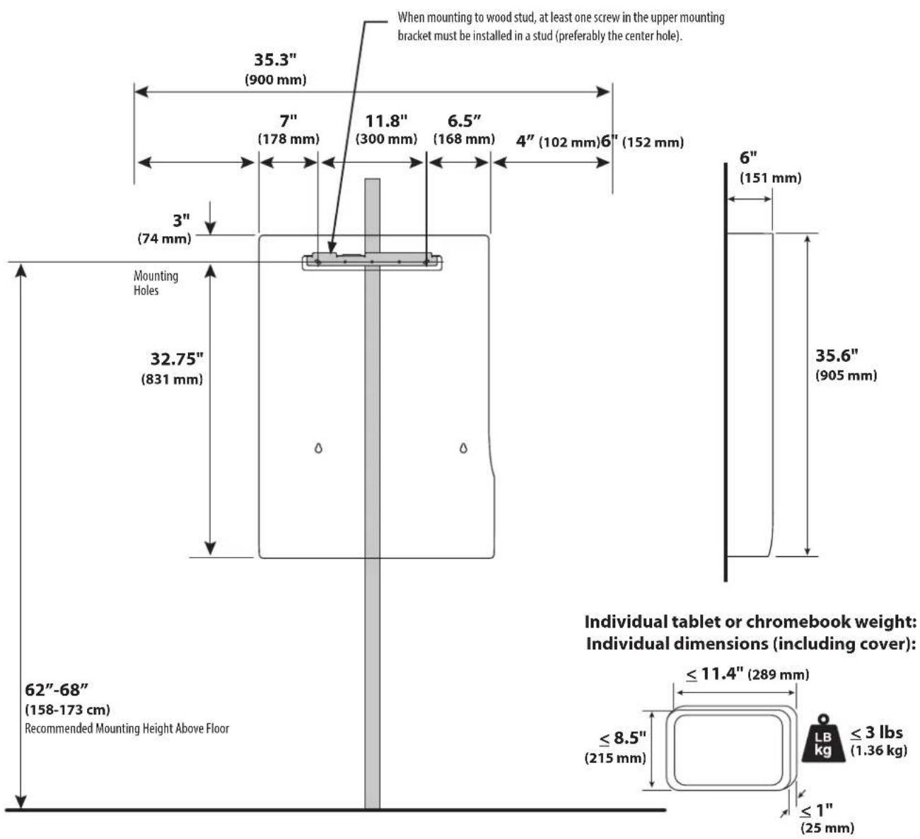
Space Requirements:
text_image
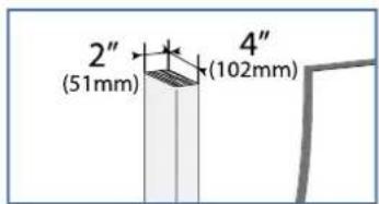
When mounting to wood stud, at least one screw in the upper mounting bracket must be installed in a stud (preferably the center hole). 35.3" (900 mm) 7" (178 mm) 11.8" (300 mm) 6.5" (168 mm) 4" (102 mm)6" (152 mm) 3" (74 mm) Mounting Holes 32.75" (831 mm) 6" (151 mm) 35.6" (905 mm) 62"-68" (158-173 cm) Recommended Mounting Height Above Floor ≤ 11.4" (289 mm) ≤ 8.5" (215 mm) ≤ 3 lbs (1.36 kg) ≤ 1" (25 mm) Individual tablet or chromebook weight: Individual dimensions (including cover):2
text_image
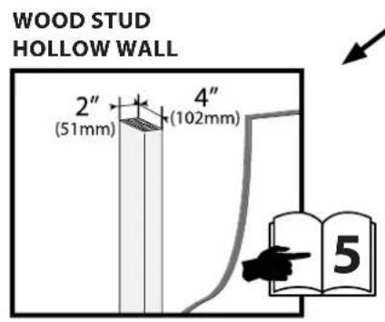
WOOD STUD HOLLOW WALL 2" (51mm) 4" (102mm) 5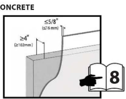
text_image
ONCRETE ≥4" (≥102mm) ≤5/8" (≤16 mm) 8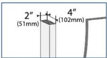
text_image
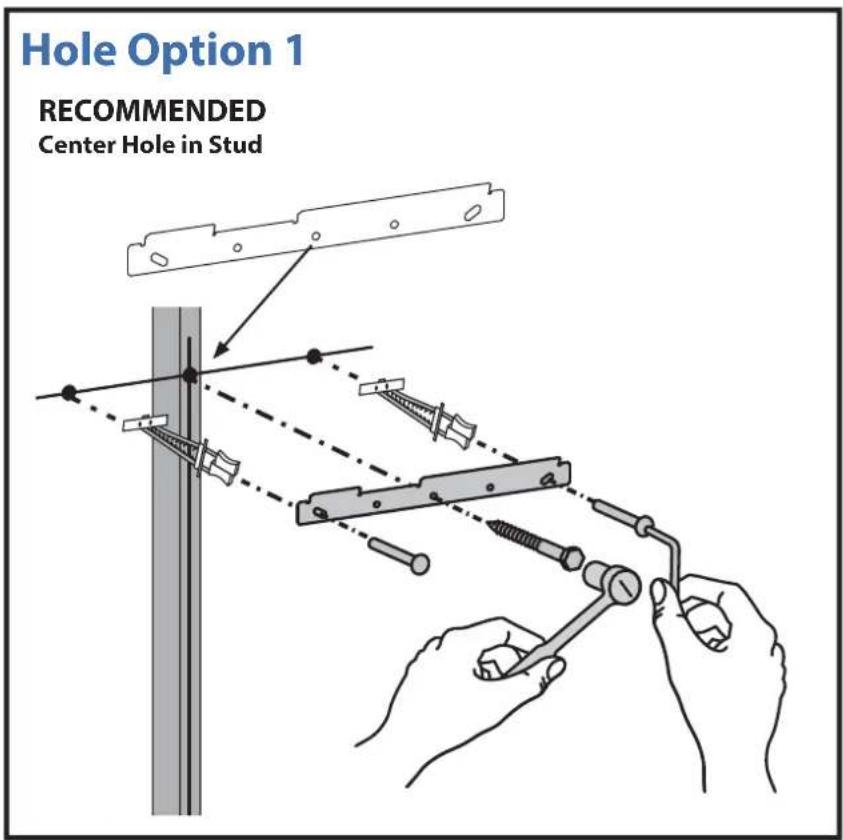
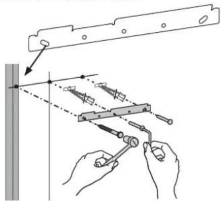
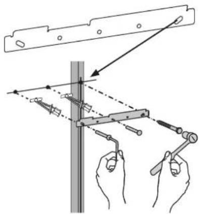
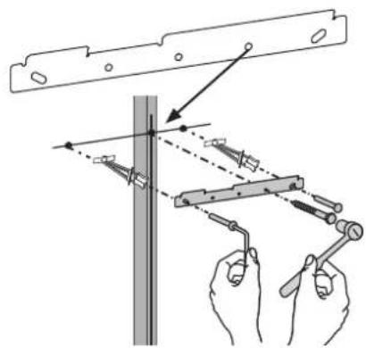
2" (51mm) 4" (102mm)a First Choose a Hole Option:
The stud can be located at one of fi ve mounting holes on the top bracket. While the fi rst option (center hole of bracket) is recommended, you should consult with a construction professional to confi rm which method is best suited for your particular situation.
After you decide on a Hole Option, follow attachment instructions on the following page.
text_image
Hole Option 1 RECOMMENDED Center Hole in StudHole Option 2
Extreme Left Hole in Stud
text_image
Technical diagram showing hands using a tool to adjust or install a mechanical component, with dashed lines indicating alignment or adjustment.Hole Option 3 Hole Option 4
Extreme Right Hole in Stud
text_image
Technical diagram showing hands using a tool to adjust or install a mechanical component, with directional arrows indicating movement.Middle Right Hole in Stud
text_image
Technical diagram showing hands using a tool to measure a vertical pole with alignment guides and force vectorsHole Option 5
Middle Left Hole in Stud
text_image
Technical diagram showing hands using a tool to adjust or install a metal bracket, with arrows indicating direction of movement.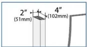
text_image
2" (51mm) 4" (102mm)b
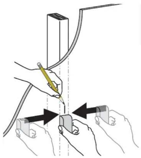
Find stud and draw a mark. Put a mark on the stud 62"-68" (158-173 cm) from floor.
natural_image
Illustration of hands using a tool to adjust or install a component, with arrows indicating movement (no text or symbols present)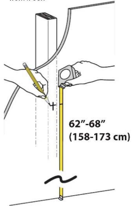
text_image
62"-68" (158-173 cm)d
text_image
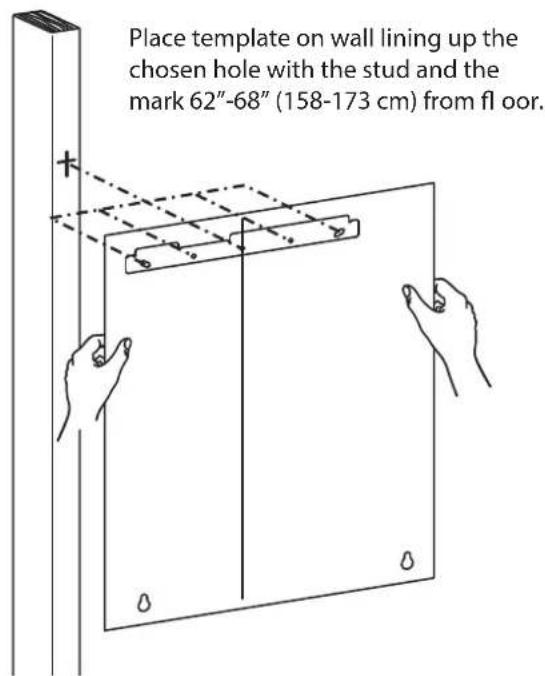
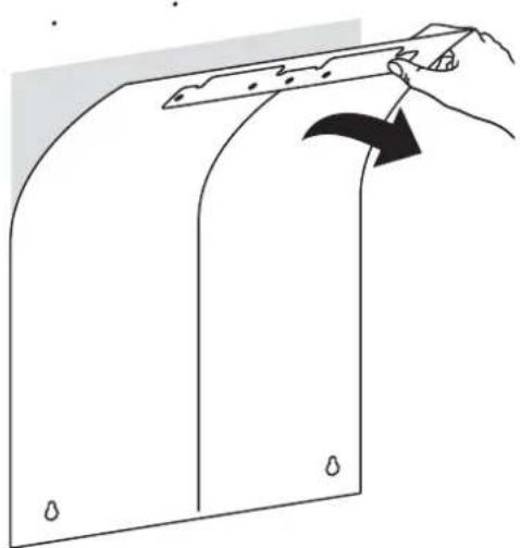
Place template on wall lining up the chosen hole with the stud and the mark 62"-68" (158-173 cm) from fl oor.e
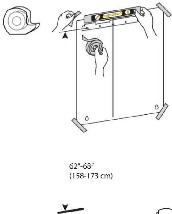
Secure template to wall.
text_image
62"-68" (158-173 cm)
text_image
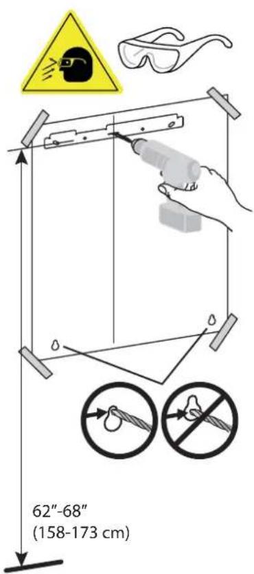
2" (51mm) 4" (102mm)- Drill the three holes for the top bracket that correspond with the hole option determined on previous page.
- Drill the bottom two holes.
text_image
62"-68" (158-173 cm)
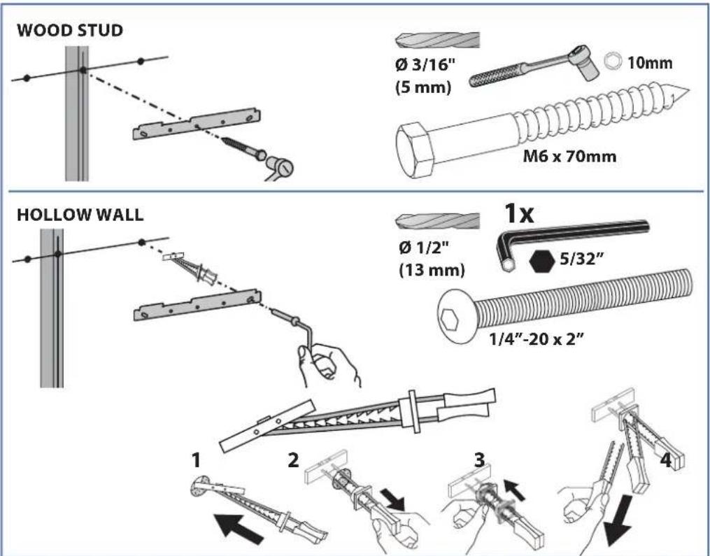
NOTE: Use the ∅ 3/16" (5 mm) drill bit when drilling directly into the wood stud. Use the ∅ 1/2" (13 mm) drill bit when drilling into the hollow wall for the anchors. Use hollow wall anchors where ever a screw does not get inserted directly into the wood stud.
text_image
WOOD STUD Ø 3/16" (5 mm) 10mm M6 x 70mm HOLLOW WALL Ø 1/2" (13 mm) 1x 5/32" 1/4"-20 x 2" 1 2 3 4g
natural_image
Line drawing of a hand holding a tool interacting with a curved panel or panel (no text or symbols present)h
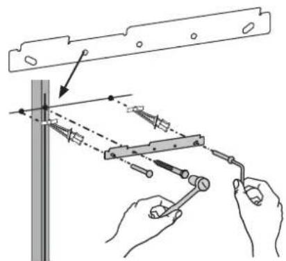
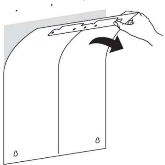
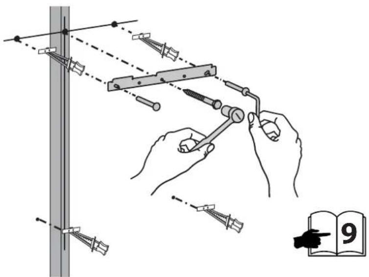
Insert anchors then attach bracket to wall according to the hole option determined on previous page. Verify wall bracket is level before tightening screws.
text_image
Diagram illustrating a mechanical setup with hands operating a tool, showing alignment and assembly steps, alongside an open book labeled '9'.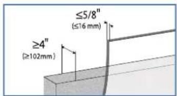
text_image
≤5/8" (≤16 mm) ≥4" (≥102mm)CONCRETE
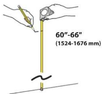
a Put a mark on the stud 62"-68" (158-173 cm) from floor.
text_image
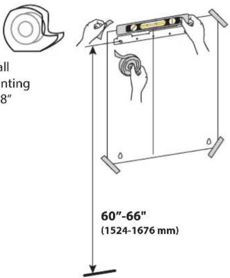
60"-66" (1524-1676 mm)b Attach template to the wall lining up the chosen mounting holes with the mark 62"-68" (158-173 cm) from floor.
text_image
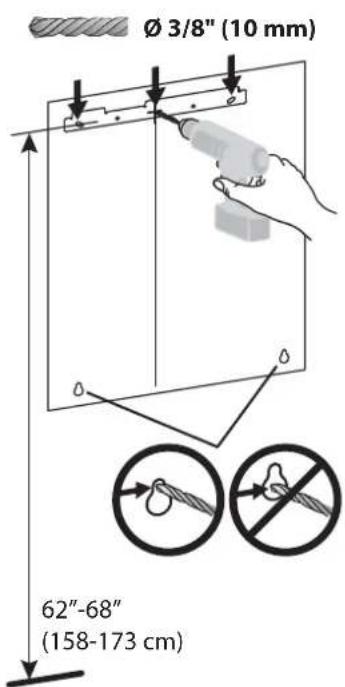
all mnting 8" 60"-66" (1524-1676 mm)C Drill the top 3 holes, then the bottom two holes.
text_image
Ø 3/8" (10 mm) 62"-68" (158-173 cm)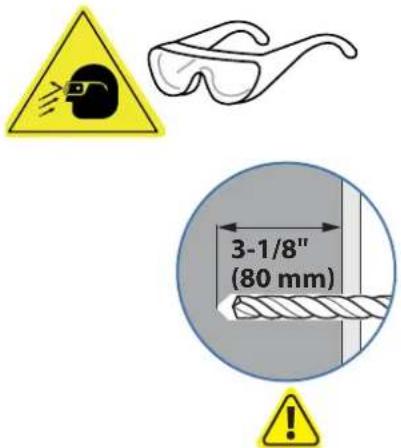
text_image
3-1/8" (80 mm)WARNING:
Mounting holes must be at least 3-1/8" (80mm) deep and must be located within solid concrete, not mortar or covering material. If you drill into an area of concrete that is not solid, reposition mounting holes until both anchors can be fully inserted into solid concrete!
d
natural_image
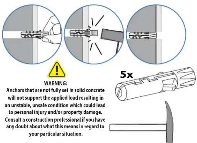
Simple line drawing of a hand holding a rectangular object with a handle, showing an arrow indicating direction (no text or symbols)e Insert anchors into holes, then attach mounting bracket.
text_image
WARNING: Anchors that are not fully set in solid concrete will not support the applied load resulting in an unstable, unsafe condition which could lead to personal injury and/or property damage. Consult a construction professional if you have any doubt about what this means in regard to your particular situation.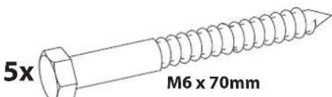
text_image
5x M6 x 70mm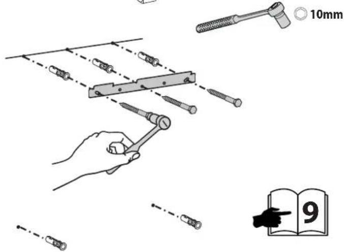
text_image
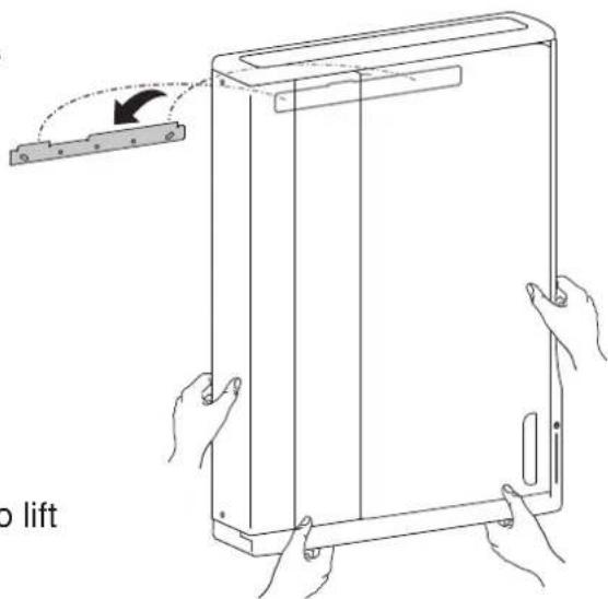
10mm 93 Hang unit onto top bracket.
text_image
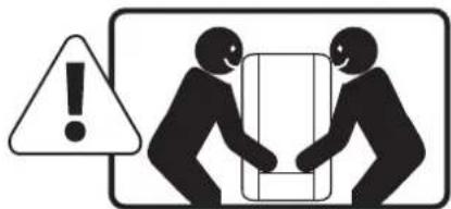
Warning symbol showing a person holding a document with an exclamation mark, indicating caution or hazard.Warning: 2 people are required to lift this product.
natural_image
Line drawing of a device being lifted by a mechanical component (no text or symbols)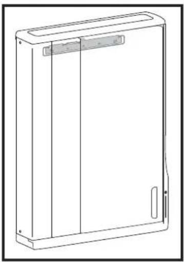
natural_image
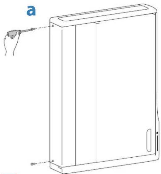
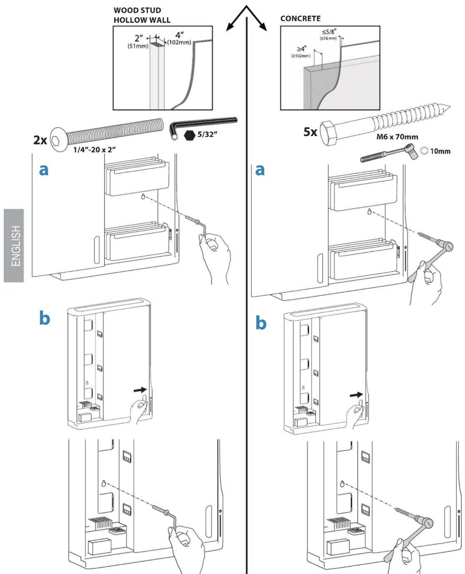
Line drawing of a rectangular electronic device with a lid and side ports (no text or symbols)4 a. Remove two screws on left side. Save screws for reattaching cover. b. Unlock door and turn wing knob 90° clockwise.
natural_image
Line drawing of a rectangular device with a hand holding a tool, no text or symbols present
natural_image
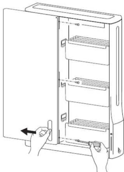
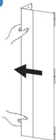
Line drawing of a hard disk organizer with a key inserted, alongside an inset showing hand using a tool near the lid (no text or symbols)5 a. Open door and remove these 3 screws. Save screws for reattaching cover. b. Remove left cover
a
natural_image
Line drawing of hands installing or adjusting a refrigerator panel with an arrow indicating left-hand rule (no text or symbols present)b
natural_image
Diagram showing two hands holding a rectangular panel with an arrow indicating leftward movement (no text or symbols)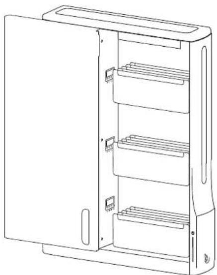
natural_image
Line drawing of a multi-tiered refrigerator unit with open door and internal shelves (no text or symbols)6
a. Secure unit to wall by inserting screw through back wall and into bottom right wall anchor.
b. Close door, then insert screw through back wall and into bottom left wall anchor.
888-61-070-G-02 rev. C·01/14
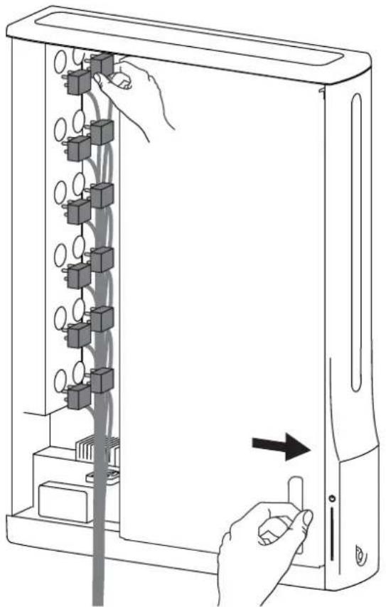
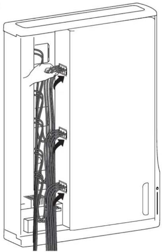
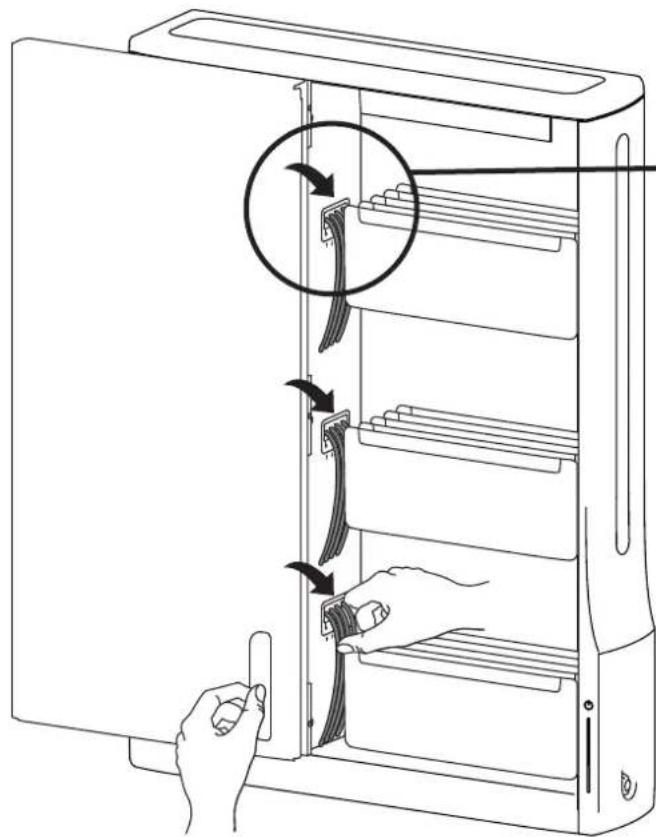
7 a. Plug in all the tablet power cables into the outlets inside. b. Route cables through the access holes. c. Open door an pull cables through the access holes.
a
natural_image
Line drawing of hands operating a server rack with connected components, showing internal wiring and a directional arrow (no text or symbols)b
natural_image
Line drawing of a server rack with cable connections and a hand inserting cables (no text or symbols)C
natural_image
Line drawing of a server rack with hand inserting cable to a door panel (no text or symbols)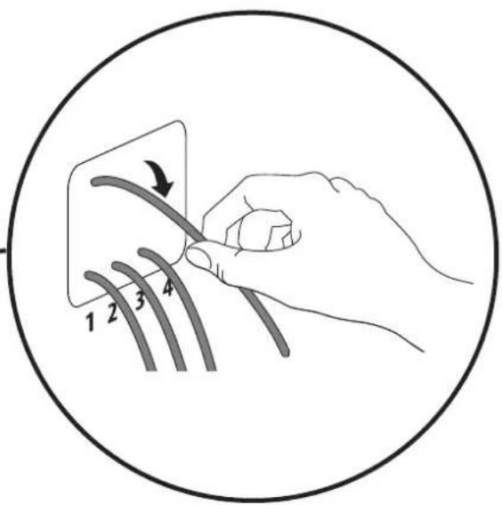
text_image
1 2 3 48
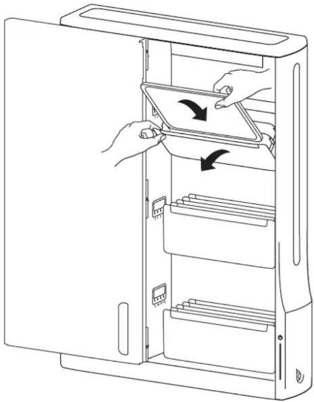
Pull out tablet tray and insert tablet.
NOTE: Tablet should be positioned so power plug is at top or left side.
natural_image
Line drawing of a computer tower with two hands inserting a tablet into the case (no text or symbols)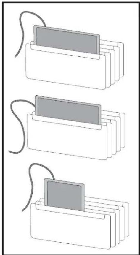
natural_image
Three schematic diagrams of stacked rectangular components with coiled wires, no text or symbols present9
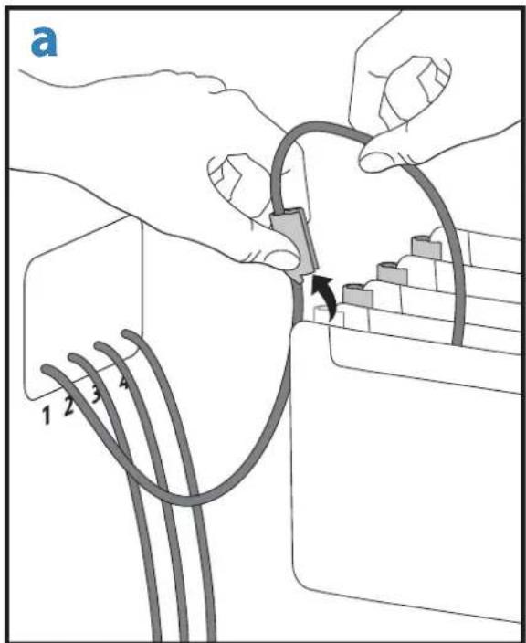
a. Pull cable clip off of tablet slot and route cable through clip, then reattach cable clip.
NOTE: Leave enough slack in cable to plug into tablet.
b. Plug tablet cables into tablets.
NOTE: When tablet is removed, store unconnected cable in the appropriate tablet slot.
text_image
a 1 2 3 4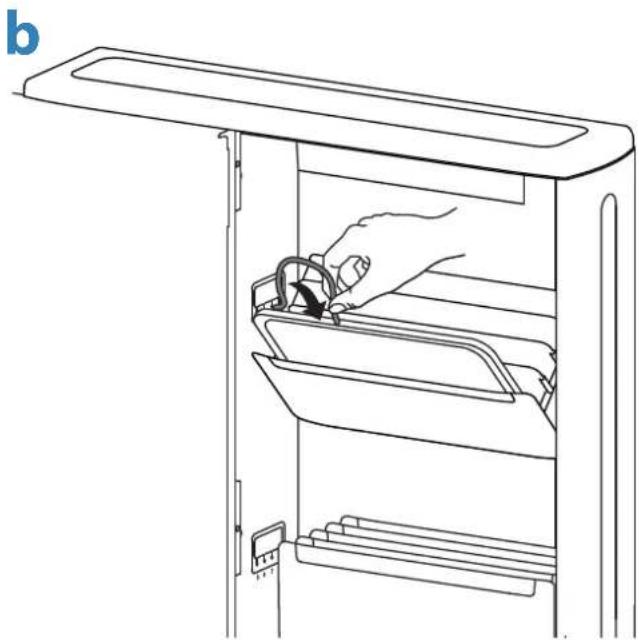
natural_image
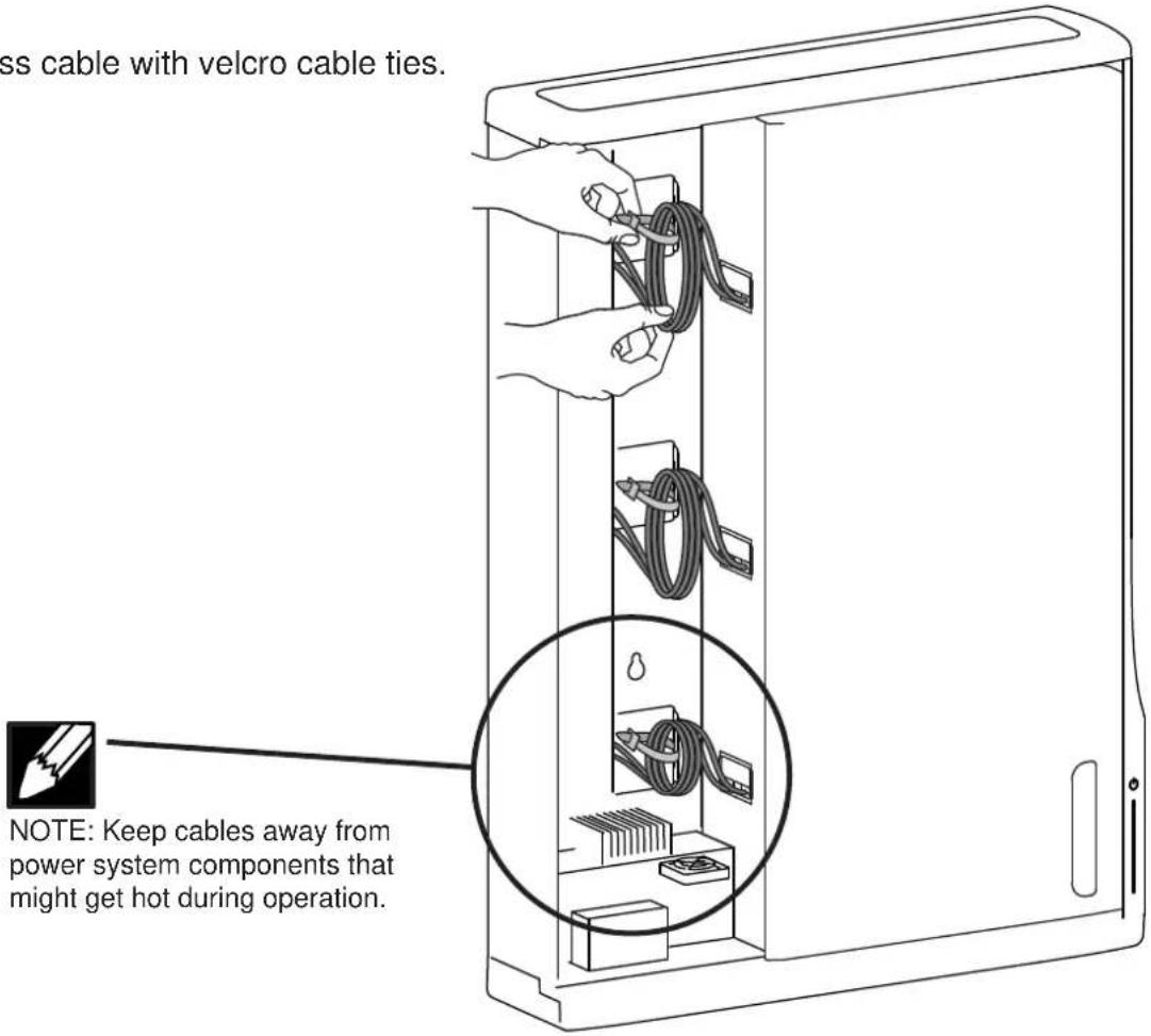
Line drawing of a hand inserting into a refrigerator drawer (no text or symbols)10 Tie up excess cable with velcro cable ties.
text_image
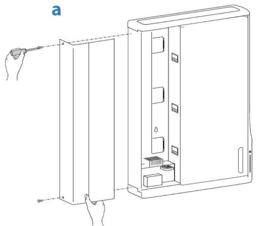
ss cable with velcro cable ties. NOTE: Keep cables away from power system components that might get hot during operation.11 a. Attach left cover with 2 screws saved from removal of cover. b. Open door and attach 3 inside screws saved from removal of left cover
natural_image
Line drawing of a device interior with hand operating a tool, showing internal components and alignment lines (no text or symbols)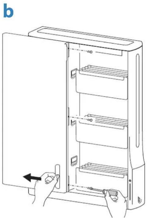
natural_image
Line drawing of a refrigerator interior with hands holding the door and a tool, showing internal shelves and casing (no text or symbols)12
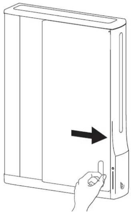
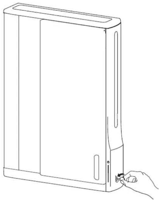
a. Close door.
b. Lock door by rotating wing knob 90° counterclockwise.
a
natural_image
Line drawing of a hand inserting a cable into a desktop computer case (no text or symbols)b
natural_image
Line drawing of a desktop computer tower with a hand inserting a cable to its side panel (no text or symbols)13
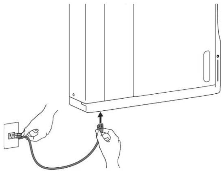
Plug power cable into bottom access and then into wall outlet to start charging.

natural_image
Line drawing of hands connecting a wall-mounted device to a power outlet cable (no text or symbols)Tablet Charging
text_image
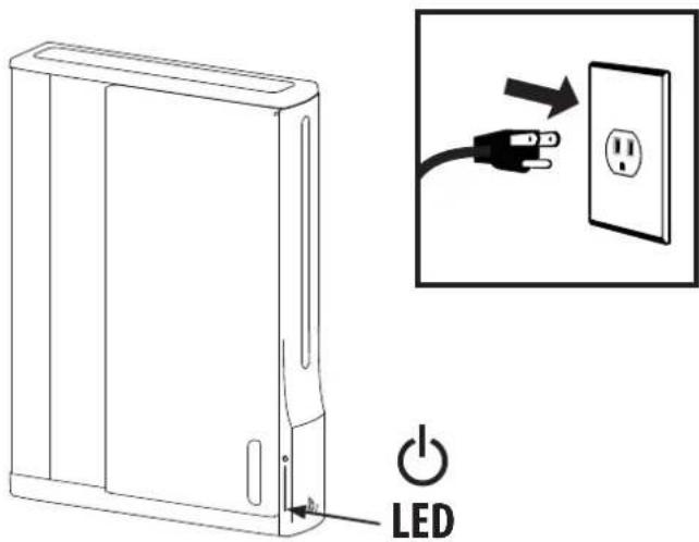
LEDTo begin charging the tablets, plug in the power cord.
The power cord is used to turn the power on and off. Charging occurs whenever the power cord is connected to an outlet.

NOTE: The power cord acts as the connect/disconnect device switching power off and on. The socket outlet shall be installed near the equipment and shall be easily accessible.

Power Indicator – Communicates charge status with the following signals:
| Light Description | |
| Off No power to the module. | |
| On - solid Tablets or Chromebooks are charging. | |
Specifications
Dimensions
26.4"W x 35.6"H x 5.9"D (669 x 905 x 151 mm)
Weight (w/o equipment)
64.5 lbs (29.3 kg)
Rated weight capacity
44.4 lb (20.1 kg)
Maximum tablet or chromebook size
Individual dimensions (including cover): up to 11.4" H x 8.5" W x 1.0" D (290 x 216 x 25 mm) Individual tablet or chromebook weight: up to 3 lb (1.4 kg)
Cooling/ventilation
One 12V DC continuous operation fan
Shipping dimensions
40.9" x 28.9" x 8.4" (1040 x 735 x 214 mm)
Shipping weight
77 lb (34.9 kg)
Power system
Part number Power System DM12-1005-1 Input: 100-120V\~, 12A, 50/60 Hz DM12-1005-2 Input: 220-240V\~, 8A, 50/60 Hz DM12-1005-3 Input: 220-240V\~, 8A, 50/60 Hz DM12-1005-4 Input: 220-240V\~, 8A, 50/60 Hz DM12-1005-5 Input: 220-240V\~, 8A, 50/60 Hz DM12-1005-6 Input: 100-120V\~, 12A, 50/60 Hz
Environmental
Temperature range: Operating 0° to 30°C (32° to 86°F) Storage -40° to 60°C (-40° to 140°F) Relative humidity (maximum): Operating 10%–90% (non condensing) Storage 5%–95% (non condensing) Altitude (maximum): 2000 m (6,562 ft)
Compatibility:
Tablets and chromebooks
Cleaning and Maintenance
| Equipment Electric SafetyThere are specific risks associated with the use of equipment having power cables. You must be aware of, and avoid these risks when this product is located in close proximity to children. | |
| WARNING: Failure to observe the following Electrical Safety notices can result in fi re or death by electric shock. | |
| Electrical cables can be hazardous. Misuse can result in fi re or death by electrical shock.Double Pole / Neutral FusingInspect power cables thoroughly before each use.Do not use cables that are damaged.Insert the plug completely into the outlet.Grasp the plug to remove from the outlet.Do not unplug by pulling on the cable.Do not use excessive force to make connections.Do not plug the cable into an extension cable.Do not remove, bend or modify any metal prongs or pins of cable.Do not drive, drag or place objects over the cable.Do not walk on the cable.Avoid overheating. Uncoil the cable and do not cover it with any material.Do not run cable through doorways, holes in ceilings, walls or floors. | |
| Keep this product away from water.Do not use it when wet.Do not place this product in close proximity to fl ammable liquids or gases. | |
| This product is intended for use only with loading as indicated. Use with loads greater than indicated may result in instability causing possible injury. | |
| The power cord acts as the connect/disconnect device switching power off and on. The socket outlet shall be installed near the equipment and shall be easily accessible. | |
| CAUTION: Changes or Modifications not expressly approved by Ergotron could void the user's authority to operate the equipment. | |
| Use SafetyThere are specific risks associated with the use of this product (for charging or storage). You must be aware of, and avoid these risks when this product is located in close proximity to children. | |
| WARNING: Failure to observe the following Use Safety notices may result in serious personal injury or equipment damage. | |
| Only Adults should use this product.Do not allow anyone to climb or hang on this product.Do not block the fans and vent openings. To prevent overheating, leave at least 127 mm (4-inch) clearance around fans and vents.This product is designed to be used indoors only.Do not use this product to store equipment other than what has been noted in this guide.Do not use this product to store liquids or cleaning supplies.Do not place heavy objects on this product.- The maximum weight capacity is 44.4 lbs (20.1 kg). |

This device complies with Part 15 of the FCC Rules. Operation is subject to the following two conditions: 1) This device may not cause harmful interference. 2) This device must accept any interference received, including interference that may cause undesired operation.
CAN ICES-3(A) / NMB-3(A).
この装置は、クラスA情報技術装置です。
この装置を家庭環境で使用す
Service and Warranty
For service and warranty visit www.ergotron.com
For local customer care phone numbers visit: http://contact.ergotron.com

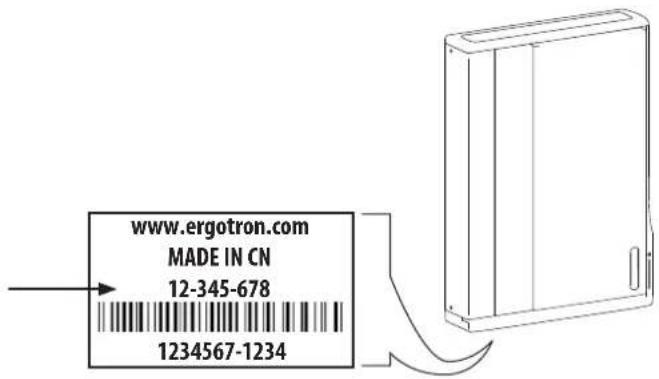
NOTE: When contacting customer service, reference the serial number.
text_image
www.ergotron.com MADE IN CN 12-345-678 1234567-1234
ERGOTRON
While Ergotron, Inc. makes every effort to provide accurate and complete information on the installation and use of its products, it will not be held liable for any editorial errors or omissions (including those made in the process of translation from English to another language), or for incidental, special or consequential damages of any nature resulting from furnishing this instruction and performance of equipment in connection with this instruction. Ergotron, Inc. reserves the right to make changes in the product design and/or product documentation without notification to its users. For the most current product information, or to know if this document is available in languages other than those herein, please contact Ergotron. No part of this publication may be reproduced, stored in a retrieval system, or transmitted in any form or by any means, electronic, mechanical, photocopying, recording or otherwise without the prior written consent of Ergotron, Inc., 1181 Trapp Road, Eagan, Minnesota, SS121, USA Patents Pending and Patented U.S. & Foreign. Ergotron is a registered trademark of Ergotron, Inc.
Americas Sales and
Corporate Headquarters
EMEA Sales
St. Paul, MN USA
(800) 888-8458
+1-651-681-7600