HM-LC-Bl1-SM - Home Automation Homematic IP - Free user manual and instructions
Find the device manual for free HM-LC-Bl1-SM Homematic IP in PDF.


| Product Type | Wall Switch Actuator (1-channel) |
| Brand | Homematic IP |
| Model | HM-LC-Bl1-SM |
| Category | Home Automation |
| Dimensions | 80 x 80 x 40 mm |
| Weight | 70 g |
| Power Supply | 230 V AC, 50 Hz |
| Max Load | 2300 W (resistive) |
| Wireless Protocol | Homematic IP (868 MHz) |
| Range | Up to 300 m (open field) |
| Mounting | In-wall flush box (60 mm) |
| Operating Temperature | -10°C to +50°C |
| Protection Class | IP20 |
| Functions | Switch on/off, status feedback, schedule, remote control via Homematic IP app |
| Compatibility | Homematic IP central control unit (CCU3 or Access Point) |
| Maintenance & Cleaning | Wipe with a dry, soft cloth. Do not use liquids. |
| Safety | Installation only by qualified electrician; disconnect power before mounting. |
| Spare Parts & Repairability | No user-replaceable parts; device must be replaced if defective. |
| Warranty | 2 years |
| Certifications | CE, RED |
Frequently Asked Questions - HM-LC-Bl1-SM Homematic IP
User questions about HM-LC-Bl1-SM Homematic IP
0 question about this device. Answer the ones you know or ask your own.
Ask a new question about this device
Download the instructions for your Home Automation in PDF format for free! Find your manual HM-LC-Bl1-SM - Homematic IP and take your electronic device back in hand. On this page are published all the documents necessary for the use of your device. HM-LC-Bl1-SM by Homematic IP.
USER MANUAL HM-LC-Bl1-SM Homematic IP
text_image
HomeMaticPrinted in Hong Kong
text_image
L N PE PEN L SLS1S2 2 L 1 KL2 KL3 KL1 M 1▲ 2▼ 1▲ 2▼text_image
L N PE 1~+ N 2~+ N AC-H 230V/50Hz KL3 KL2 KL1 KL4 KL5 LF N 1~+ N 2~+ NHM-LC-Dim2T-SM
text_image
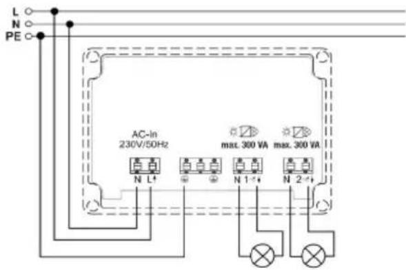
L N PE AC-in 230V/50Hz max. 300 VA max. 300 VA N L+ N 1- N 2-+1st English edition 01/2010
Documentation © 2009 eQ-3 Ltd. Hong Kong
All rights reserved. No parts of this manual may be reproduced or processed in any form using electronic, mechanical or chemical processes in part or in full without the prior explicit written permission of the publisher.
It is quite possible that this manual has printing errors or defects. The details provided in this manual are checked regularly and corrections are done in the next edition. We do not assume any liability for technical or printing errors.
All registered trade marks and copyrights are acknowledged.
Printed in Hong Kong
We reserve the right to make changes due to technical advancements without prior notice.
73951 / V 2.1
Table of Contents
1 Information concerning these instructions ... 34
2 Hazard information....34
3 Function 37
4 General system information on HomeMatic .. 43
5 General information on radio operation ..... 43
6 Installation 45
7 Start up....51
7.1 Simple operating functions on the device....51
7.2 Teaching-in.....52
8 Operation 52
8.1 Switching actuator ..... 53
8.2 Blind actuator 53
8.3 Dimming actuator 53
9 Resetting to the initial state ..... 53
10 Device LED feedback.....54
10.1 Flash codes 54
10.2 Operational status display ..... 54
11 Behavior after power restoration ..... 55
12 Maintenance and cleaning ..... 56
13 Other notes on operation ..... 56
14 Technical specifications ..... 57
1 Information concerning these instructions
Read these instructions carefully before beginning operation with your HomeMatic components. Keep the instructions handy for later consultation! Please hand-over the operating manual as well when you hand-over the device to other persons for use.
Symbols used:

Attention! This indicates a hazard.

Note. This section contains additional important information!
2 Hazard information

The described actuators are part of a building installation. When planning and setting up electrical systems, the pertinent standards and regulations of the respective country of installation are to be observed.

Operating the device is only permitted with a 230 V/50 Hz alternating current network. Work on the 230 V network is only permitted by qualified electricians (in accordance with VDE 0100).

Always observe the applicable accident prevention regulations. Disconnect the power to devices before working on them to prevent electrocution (switch circuit breaker).

Ignoring installation instructions can cause fires or other hazards.

Load the devices to the specified limits only.

An overload can cause destroy the device, cause fires or electrical accidents.

The devices are not intended to be isolated.

Do not open the device. It does not contain any parts to be maintained by the user. There is a risk of electrical shock by opening
the device. Make sure that the specified wiring and wire cross-sections are used when connecting to device terminals.
Switch actuator:
Follow all technical specifications, especially the maximum permitted switching capacity of the relay and type of consumer to be connected, before connecting the consumer! All load specifications refer to resistive loads!
Blind actuator:
The actuator is only suitable for 230V a.c. motors! Never connect three-phase a.c. motors or d.c. motors! If motors are connected to the output in parallel with the actuator, make sure to observe the motor manufacturer's specifications. The motors can be damaged otherwise. Use only blinds or shutters with limit switch (mechanical or electronic)! Check the limit switch for the connected motors for proper adjustment before starting the blind actuator!
Use only mains power capable buttons and wires for connecting to button inputs!
Dimming actuator:
Make sure to observe the applied load! The dimmer is only suitable for light bulbs and for low voltage NV halogen lamps with magnetic transformers!
The devices are not intended to be isolated. The load is not electrically isolated from the mains.
Fuse every transformer on the primary side according to the manufacturer's specifications when working with conventional transformers.
Use only safety transformers that conform with DIN EN 61558-2-6 (VDE 0570 part 2-6).
3 Function
The actuators control connected consumers based on the radio commands received. Commands are sent out by actuating buttons, remote operations or from a software interface. In addition, it is possible to control actuators with sensors that are taught.
The sensors send (like a button) a command when an event occurs. More information is provided in the instructions for the respective sensor.
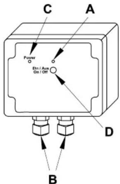
HM-LC-Sw1-SM
text_image
C Power Elm / Aus On / Off A D B(A) Channel LED
(B) Connecting wire terminals
(C) Power LED
(D) Channel button
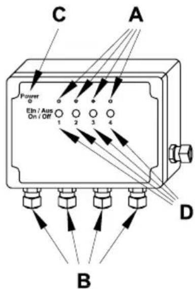
HM-LC-Sw4-SM
text_image
C A Power Etn / Aus On / Off 1 2 3 4 D B(A) Channel LED
(B) Connecting wire terminals
(C) Power LED
(D) Channel button
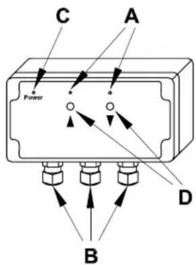
HM-LC-BI1-SM
text_image
C A Power D B(A) Channel LED (UP/DOWN)
(B) Connecting wire terminals
(C) Power LED
(D) Channel button (UP/DOWN)
HM-LC-Dim2L-SM
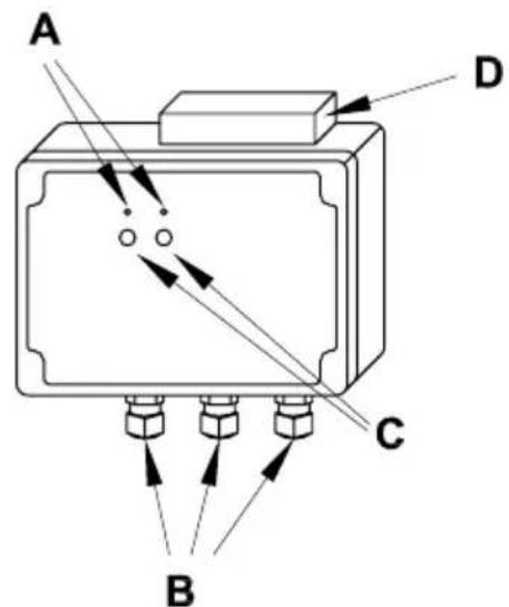
text_image
A D C B(A) Channel LED
(B) Connecting wire terminals
(C) Channel button
(D) Cooler
HM-LC-Dim2T-SM
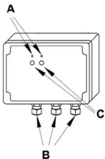
text_image
A B C(A) Channel LED
(B) Connecting wire terminals
(C) Channel button
4 General system information on HomeMatic
This device is a part of the HomeMatic home control system and works with the bidirectional BidCoS® wireless protocol.
All devices are delivered in a standard configuration. The functionality of the device can also be configured with a programming device and software.
Further resulting functionality and the additional functions provided in the HomeMatic system combined with other components are described in the separate Configuration Instructions and in the HomeMatic WebUI manual.
All current technical documents and updates are provided under www.HomeMatic.com.
5 General information on radio operation
The radio transmission is on a non-exclusive transmission path which means that there is a possibility of interference occurring.
Other interfering sources can be caused by switching operations, electrical motors or defective electrical devices.

The range of transmission within buildings can greatly deviate from open air distances. Besides the transmitting power and the reception characteristics of the receiver, environmental influences such as humidity in the vicinity and local structures also play an important role.
Hereby eQ-3 Entwicklung GmbH, declares that this device conforms with the essential requirements and other relevant regulations of Directive 1999/5/EC.
The full declaration of conformity is provided under www.HomeMatic.com.
6 Installation
The surface-mount actuators are suitable for installing outdoors and in humid rooms because of the increased degree of protection.
Remove the transparent housing cover for mounting and installing. The holes for fastening to the wall are visible underneath.
In order to access the connection terminals, remove the gray cover plate.
The installation of the described actuators is shown in the following connection diagrams. Connect the actuators to L and N for the supply. Run the channel circuit to the consumer.
HM-LC-Sw1-SM
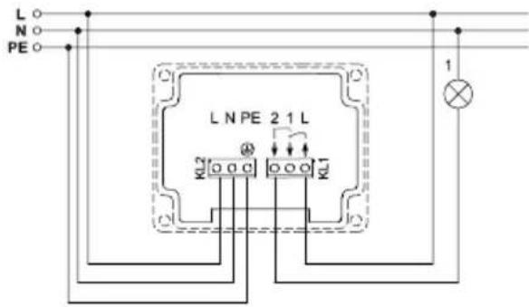
text_image
L N PE C L N PE 2 1 L KL2 KL1 1| L External conductor connection |
| N Neutral connection |
| PE PE connection |
| 2 Switched channel(change-over relay Item 1) |
| 1 Switched channel(change-over relay Item 2) |
| L External conductor connection |
HM-LC-Sw4-SM
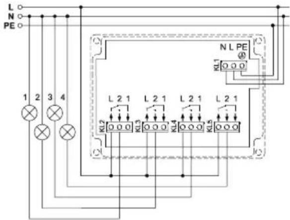
text_image
L N PE 1 2 3 4 KL2 L 2 1 L 2 1 L 2 1 L 2 1 KL3 KL5 NL PE KL1| L External conductor connection |
| N Neutral connection |
| PE PE connection |
| 2 Switched channel(change-over relay Item 1) |
| 1 Switched channel(change-over relay Item 2) |
| L External conductor connection |
HM-LC-BI1-SM
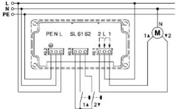
text_image
L N PE PEN L SL S1 S2 2 L 1 KL2 KL3 KL1 M N 1▲ 2▼ -1 -1 1▲ 2▼| L External conductor connection |
| PE PE connection |
| N Neutral connection |
| L External conductor connection (device supply) |
| SL Lopped channel in device for controlling button inputs |
| S1 Button input (Channel) "UP" |
| S2 Button input (Channel) "DOWN" |
| 2 Switched channel "DOWN" |
| L External conductor connection (motor supply) |
| 1 Switched channel "UP" |
HM-LC-Dim2L-SM
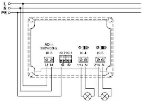
text_image
L N PE AC-In 230V/50Hz KL3 KL2 KL1 KL4 KL5 L1 N 1+4+ N 2+4+ N| L External conductor connection | |
| N Neutral connection | |
| PE PE connection | |
| 1+ N | Dimmed phase channel 1 |
| N Neutral line channel 1 | |
| 2+ N | Dimmed phase channel 2 |
| N Neutral line channel 2 | |
HM-LC-Dim2T-SM
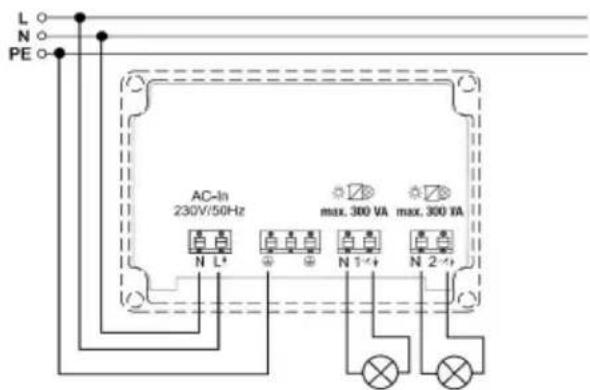
text_image
L N PE AC-In 230V/50Hz max. 300 VA max. 350 VA N L+ N 1+ N 2+| L External conductor connection | |
| N Neutral connection | |
| PE PE connection | |
| 1×+ N | Dimmed phase channel 1 |
| N Neutral line channel 1 | |
| 2×+ N | Dimmed phase channel 2 |
| N Neutral line channel 2 | |
Permitted wire cross-section for connecting to the AP actuators:
| Rigid wire [mm2] | Flexible wire without end sleeve [mm2] | Flexible wire with end sleeve [mm2] |
| 0.50 – 2.50 0.50 | - 2.50 0.50 – 2.50 |
7 Start up
7.1 Simple operating functions on the device
There is one control button per channel on the devices (one UP button and one DOWN button for the blind actuator). You can operate the actuator immediately (teaching is not required) and check for correct electrical installation. With switching and dimming actuators, you can use it to switch the channel on and off. With blind actuators, you can move the hangings up or down.

Only the brief button press is used for operation. The longer button press (holding longer than 4 seconds) switches the actuator to teach mode.
7.2 Teaching-in
Please read this section completely before starting with any teaching-in!
Teaching-in requires that both devices to be connected are put into teach mode and the desired channel must be selected for training.
The surface-mount actuators have no special teach button. Teaching a certain actuator channel requires pressing and holding the respective channel button (one of the two buttons ▲ or ▼ for the blind actuators).
Teach mode is indicated by the device LED flashing continuously.
If no teaching occurs, teach mode is automatically ended after 20 seconds. If other devices are in teach mode, these are taught.
8 Operation
After teaching, simple operating functions are available using the taught control elements.
8.1 Switching actuator
Depending on the control elements that have been taught, the switch actuator can be controlled in two button ON/OFF mode or in toggle mode.
8.2 Blind actuator
Depending on the control elements that have been taught, the blind actuator can be controlled in two button UP/DOWN mode or in toggle mode (UP/STOP/DOWN/STOP).
8.3 Dimming actuator
Depending on the learned operating element, the dimmer can be used in two button ON/OFF operation or in toggle operation ON/OFF with a brief press on the button and brighten/dim with a longer press of the button.
9 Resetting to the initial state
In order to reset the actuator to factory status, switch the device to teach mode with the (first) channel button
(hold button pressed for at least 4 seconds).
If the device is in teach mode, hold the (first) channel button pressed down for at least 4 seconds. The actuator reset is indicated by the device LED flashing quickly.
10 Device LED feedback
10.1 Flash codes
Different actuator states are indicated by the channel LED/channel LEDs flashing:
| Slow flashing Teach mode | |
| Fast flashing Reset | |
| One long, x-short (depends on the type of error) | Error |
10.2 Operational status display
As soon as the relay for a channel (or a direction for the blind actuator) is triggered, the respective channel LED will be illuminated continuously.
After configuring the actuator with the center or a programming tool, the device LED indicates other device states besides those described. More relevant information is provided in the configuration instructions for the devices and in the system manual.
11 Behavior after power restoration
After switching the operating voltage on (mains voltage returned), the actuator checks the respective components. If an error is detected, it is indicated by all channel LEDs flashing (the LEDs for both directions flash for the blind actuator). This is repeated continually and the device starts to work with the respective functionality.
If the test runs without any errors, the actuator sends a radio telegram with the respective status information.
The actuator waits a random delay time before sending so that all actuators are not sending at the same time when the power returns (after a power outage or shut-down).
During this time, the channel LEDs flash (like in teach mode). If the delay time is short, the flashing may not even be noticeable.
12 Maintenance and cleaning
This product is maintenance-free. Repairs are only to be done by trained professionals.
Dimming actuator

The device is provided with two internal device fuses for protecting the triac from greater current loads. If the device becomes overloaded and a fuse is blown, it can be replaced by a technician!

Disconnect the mains power before removing the device (switch the circuit breaker off)! Work on the 230V network is only permitted by qualified electricians (in accordance with VDE 0100).

Replace fuses with same type fuses (microfuse 5 x 20 mm, 2.5 A slow)!
13 Other notes on operation
Applicable for HM-LC-Dim2T-SM: If the device reaches too high a temperature during operation (due
to insufficient air circulation at high load, for example), the load will first of all be reduced by lowering the brightness. If the overtemperature persists, the load will be disconnected.

If the actuator is operating via the HomeMatic central control unit (CCU), please note that the central control unit will not be informed in the event of a load failure.
14 Technical specifications
Radio frequency: 868.3 MHz
Typ. outdoor range: 300 m
Power supply: 230 V / 50 Hz
Standby consumption: 0.5 W
HM-LC-Dim2L-SM: 0,8 W
HM-LC-Dim2T-SM: 1 W
Degree of protection: IP65
Protection class: II
Housing: PC
Housing color: Light gray
HM-LC-Sw1-SM
Relay: Change-over
(potential-free contacts)
Switching capacity: 16 A (resistive load)
Dimensions (H x W x D): 90 x 115 x 55 mm
HM-LC-Sw4-SM
Relay: 4 change-over
(potential-free contacts)
Switching capacity: 16 A (resistive load)
Dimensions (H x W x D): 121 x 171 x 55 mm
HM-LC-BI1-SM
Relay: 1 normally open,
1 change-over
(potential-free contacts)
Switching capacity: 4 A motor load
Operating temperature: -10 to +55 °C
Dimensions (H x W x D): 115 x 160 x 55 mm
HM-LC-Dim2L-SM
Connection power: 2 x 25–500 VA
Dimensions (H x W x D): 121 x 171 x 55 mm
HM-LC-Dim2T-SM
Connection power: 2 x 300 VA
Dimensions (H x W x D): 171 x 55 x 121 mm
Subject to technical changes.
Instructions for disposal

Do not dispose off the device as part of household garbage! Electronic devices are to be disposed of in accordance with the guidelines concerning electrical and electronic devices via the local collecting point for old electronic devices.

The CE sign is a free trade sign addressed exclusively to the authorities and does not include any warranty of any properties.