
HMW-IO-4-FM - Uncategorized Homematic IP - Free user manual and instructions
Find the device manual for free HMW-IO-4-FM Homematic IP in PDF.


| Product Type | RS485 4-Channel I/O Module (Flush-Mount) |
| Brand | Homematic IP |
| Model | HMW-IO-4-FM |
| Dimensions (H x W x D) | 24 x 27 x 20 mm |
| Weight | 30 g |
| Power Supply | 24 V DC |
| Current Consumption | 25 mA |
| Max Output Current per Channel | 15 mA |
| Communication | RS485 Bus |
| Number of Channels | 4 |
| Configurable as Inputs/Outputs | Yes (via HomeMatic Center) |
| Input Type | Potential-free button inputs (multiple per channel) |
| Non-Volatile Memory | Yes (for configuration data) |
| Installation | Indoor, flush-mount in sub-distribution |
| Load Side Wiring | 230 V, 1.5 mm² NYM cable (VDE conform) |
| Control Side Wiring | Safety extra-low voltage, 8 mm spacing from mains |
| Bus Termination | Required when using multiple modules |
| Maintenance | Maintenance-free; repairs only by trained professionals |
| Cleaning | Do not clean with liquids; wipe with dry cloth |
| Safety | Indoor use only; avoid humidity, dust, direct sunlight |
| Disposal | Electronic waste; do not dispose with household garbage |
| CE Marking | Yes |
Frequently Asked Questions - HMW-IO-4-FM Homematic IP
User questions about HMW-IO-4-FM Homematic IP
0 question about this device. Answer the ones you know or ask your own.
Ask a new question about this device
Download the instructions for your Uncategorized in PDF format for free! Find your manual HMW-IO-4-FM - Homematic IP and take your electronic device back in hand. On this page are published all the documents necessary for the use of your device. HMW-IO-4-FM by Homematic IP.
USER MANUAL HMW-IO-4-FM Homematic IP
text_image
HomeMatic
Installation and Operating Manual
RS485 4 channel I/O module flush-mount HMW-IO-4-FM
Seite 18 - 30
Printed in Hong Kong
Documentation © 2007 eQ-3 Ltd., Hong Kong
All rights reserved. No parts of this manual may be reproduced or processed in any form using electronic, mechanical or chemical processes in part or in full without the prior explicit written permission of the publisher.
It is quite possible that this manual has printing errors or defects. The details provided in this manual are checked regularly and corrections are done in the next edition. We do not assume any liability for technical or printing errors.
All registered trade marks and copyrights are acknowledged.
Printed in Hong Kong
We reserve the right to make changes due to technical advancements without prior notice.
75243 / V 1.01
Inhaltsverzeichnis
1 Information concerning these instructions. 19
2 Hazard information 19
3 Function....20
4 General system information on HomeMatic. 22
5 General information on the bus system .... 23
5.1 General information on the installation .... 23
5.2 Topology of the bus system ..... 2 4
6 Installation 26
7 Assignment of button inputs and actuator channels 27
7.1 Teaching button inputs to actuator channels 27
7.2 Clearing the assignment of button inputs to actuator channels ..... 2 9
8 Maintenance and cleaning 30
9 Technical specifications .... 3 0
1 Information concerning these instructions
Read these instructions carefully before beginning operation with your HomeMatic components.
Keep the instructions handy for later consultation!
Please hand-over the operating manual as well when you hand-over the device to other persons for use.
Symbols used:

Attention! This indicates a hazard.

Note. This section contains additional important information!
2 Hazard information

This device is to be operated indoors only and keep away from the influences of
humidity, dust and sunshine or other radiating heat sources.
3 Function
- 4 connections, optionally as inputs or outputs (via the HomeMatic Center)
- Channels configured as inputs can be configured as desired and optional actuator channels can be assigned (from other modules as well).
- As many potential-free buttons as are necessary can be connected to one input.
• Non-volatile memory for configuration data.
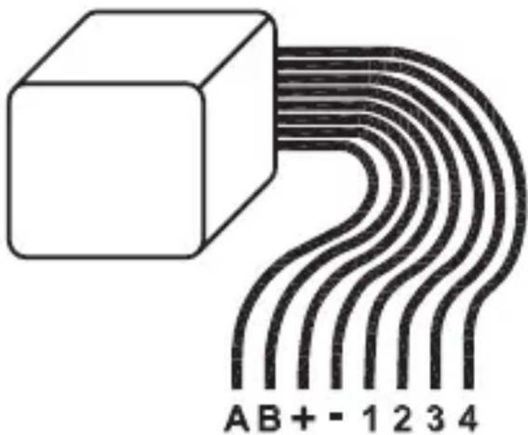
text_image
A B + - 1 2 3 4Wires used:
| A Bus A | |
| B Bus B | |
| + Bus power supply + | |
| - Bus power supply - | |
| 1 Channel | 1 |
| 2 Channel | 2 |
| 3 Channel | 3 |
| 4 Channel | 4 |
4 General system information on HomeMatic
This device is a component of the HomeMatic Home Control System.
All devices are delivered in a standard configuration. The functionality of the device can also be configured with a programming device and software.
Further resulting functionality and the additional functions provided in the HomeMatic system combined with other components are described in the separate Configuration Instructions and in the HomeMatic System Manual.
All current technical documents and updates are provided under www.HomeMatic.com.
5 General information on Bus system
5.1 General information on the installation
Basically, the connections of the HMW components can be divided into two groups. In the load side and in the control side (24 V power supply, button inputs, RS485 Bus).
Load side
Since normally a 230 V consumer is on the load side, using VDE-conforming installation wires, such as e.g. NYM wiring, etc. is required. The wire cross-section conform with the standard VDE regulations and is 1.5 mm2 for installations in the nominal load range of actuators.
Control side
On the control side however, only non-hazardous safety extra-low voltages are used. Since there is electrical isolation between the load and control sides in the module, no mains power capable wires have to be used. Using interior telecommunications wiring or comparable control wiring is recommended. Make sure however, that the wires of the load
and the control side are separated conforming with VDE regulations within the sub-distribution. Keep a minimum spacing of 8 mm between the two types of wiring.
When connecting the RS485 bus, the A terminals, the B terminals, the 24 V power supply and the ground terminal of the modules of a sub-distribution (max. 127 segments) are to be connected with one another. A connection diagram with bus system is provided in the system manual. When using several modules, a bus termination is required.
Information on the connections is provided in the respective operating instructions.
5.2 Topology of the bus system
The HMW components should always be mounted in groups of sub-divisions to provide a better overview. The number of sub-divisions that is appropriate depends on the type and size of the project and is to be defined accordingly.
Installing at least one sub-division on each level is recommended. Larger buildings may require plan-
ning several sub-divisions per level (e.g. separate for every floor). All load and control wiring should also be run in a star format to the respective sub-divisions. The power supply is done through a DIN rail power supply HMW-Sys-PS7-DR or another 24 V power supply dimensioned according to the number and total current consumption of all existing modules in the respective sub-division. If central programming and control is to be done through the HomeMatic Centre, the HMW bus lines for the individual sub-divisions and the lines coming from the control PC or a Centre should be run together in a room according to available space in order to achieve a separation of the individual bus segments and to simplify troubleshooting if necessary. Normally, this is the room in which the HomeMatic system Centre is installed.
6 Installation
Installation with four input channels
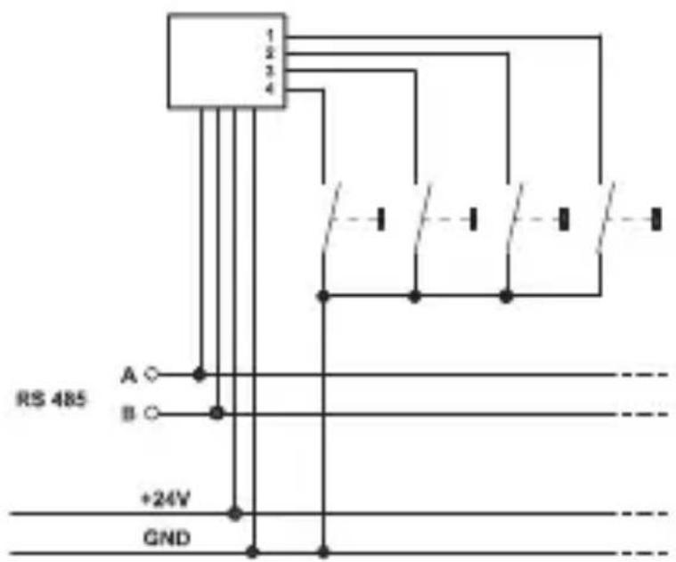
text_image
1 2 3 4 A B +24V GND RS 485The channels can be reconfigured as outputs when using the HomeMatic Center.
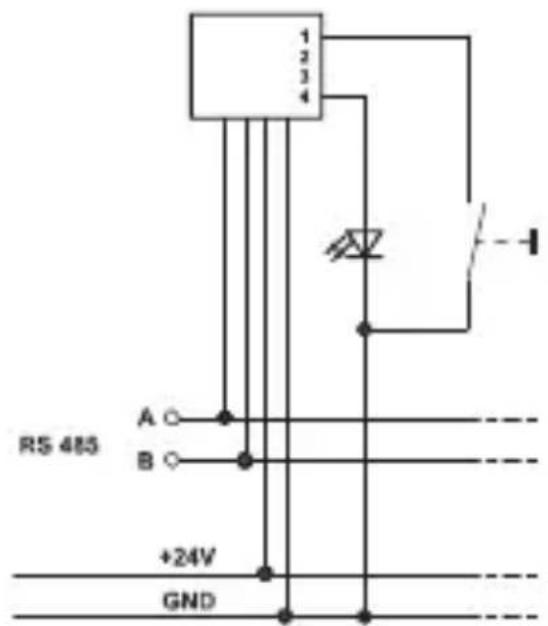
text_image
1 2 3 4 RS 485 A ○ B ○ +24V GND7 Assignment of button inputs and actuator channels
All channels of the device are configured as button inputs in delivery status. You can teach the inputs for any actuator channels on the bus.
7.1 Teaching button inputs to actuator channels

Please read this section completely before starting with any configuring!

The button inputs are not assigned to any actuator channels in factory status (not the actuator channels of the device on which they are located either)
Assignment of button inputs to actuator channels
- Press the programming button of the actuator (channel) to be assigned on the module until the channel LED flashes slowly (after approx.
3 seconds). The module is now in teach mode. - Now, actuate a button on the button input (on the same module or any other module on the
bus) that you want to assign to the actuator (channel).
- The actuator (channel) is now assigned with this switch input and the channel LED goes dark on the actuator.
- Test the assignment by pressing the respective button. The actuator (channel) should react according to the configuration of the button input.
- If you want to assign another button input to the actuator (channel), repeat this procedure.
Depending on the actuator, button inputs are taught differently:
| Actuator Button behavior | |
| Switch actuator, Dimming actuator | Taught buttons behave like toggle switches |
| Blind actuator | Depending on whether teach mode on the actuator was triggered with the ▲- or ▼- button, the button to be taught is taught as "Open" or "Close", not as a toggle button. |

If a button that was taught for an actuator is taught for the same actuator again, the old
assignment is overwritten.
7.2 Clearing the assignment of button inputs to actuator channels
Clearing the assignment of a button input and actuator (channel)
- Press the programming button of the actuator (channel) that you want to clear the assignment for until the respective channel LED switches from slow flashing to quickly flashing (after approx. 6 seconds).
- Release the button. The module is now in delete mode.
- Now, press a button on the button input of a module for which you want to clear the assignment. The channel LED on the actuator goes dark and the assignment is deleted, the actuator (channel) is no longer actuated on this switch input.
- Test the setting by actuating a button on the deleted button input, the actuator (channel) should not react.

All teach procedures can be aborted by briefly actuating the programming button.
8 Maintenance and cleaning
This product is maintenance-free. Repairs are only to be done by trained professionals.
9 Technical specifications
Communication: RS485-Bus
Voltage supply: 24 V / DC
Current consumption: 25 mA
Max. output current: 15 mA
Housing dimensions: 24 x 27 x 20 mm
(H x W x D) (with-out connecting lines)
Weight: 30 g
Length of the connecting lines: 125 mm
Instructions for disposal:
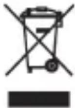
Do not dispose off the device as part of household garbage! Electronic devices are to be disposed of in accordance with the guidelines concerning electrical and electronic devices via the local collecting point for old electronic devices.

The CE sign is a free trade sign addressed exclusively to the authorities and does not use any warranty of any properties.

text_image
eQBeQ-3 AG
Maiburger Straße 29
D-26789 Leer
www.eQ-3.com