
MQ 50 - Pregnant RCF - Free user manual and instructions
Find the device manual for free MQ 50 RCF in PDF.


User questions about MQ 50 RCF
0 question about this device. Answer the ones you know or ask your own.
Ask a new question about this device
Download the instructions for your Pregnant in PDF format for free! Find your manual MQ 50 - RCF and take your electronic device back in hand. On this page are published all the documents necessary for the use of your device. MQ 50 by RCF.
USER MANUAL MQ 50 RCF
TWO-WAY COMPACT MONITOR SPEAKER SYSTEM DIFFUSORE MONITOR COMPATTO A DUE VIE

text_image
Monitor seriesUser manual Manuale d'uso
natural_image
Black RCF audio amplifier speaker with mesh grille and logo (no text or symbols on body)the rules of sound

text_image
RCFIMPORTANTE
Before connecting and using this product, please read this instruction manual carefully and keep it on hand for future reference. The manual is to be considered an integral part of this product and must accompany it when it changes ownership as a reference for correct installation and use as well as for the safety precautions.
RCF S.p.A. will not assume any responsibility for the incorrect installation and / or use of this product.

WARNING: To prevent the risk of fire or electric shock, never expose this loudspeaker to rain or humidity and dust, but the case this has been expressly designed and made to get a suitable IP protection grade (indicated in the product specifications).
SAFETY PRECAUTIONS
- All the precautions, in particular the safety ones, must be read with special attention, as they provide important information.
- Loudspeaker lines (amplifier outputs) can have a sufficiently high voltage (i.e. 100 V) to involve a risk of electrocution: never install or connect this loudspeaker when the line is alive.
- Make sure all connections have been made correctly and the loudspeaker input voltage (in a constant voltage system) or its impedance is suitable for the amplifier output.
- Protect loudspeaker lines from damage; make sure they are positioned in a way that they cannot be stepped on or crushed by objects.
- Make sure that no objects or liquids can get into this product, as this may cause a short circuit.
- Never attempt to carry out any operations, modifications or repairs that are not expressly described in this manual.
Contact your authorized service centre or qualified personnel should any of the following occur:
- the loudspeaker does not function (or works in an anomalous way);
• the cable has been damaged; - objects or liquids have got into the unit;
-
the loudspeaker has been damaged due to heavy impacts / fire.
-
Should the loudspeaker emit any strange odours or smoke, remove it from the line after having switched the amplifier off.
-
Do not connect this product to any equipment or accessories not foreseen.
For suspended installation, only use the dedicated anchoring points and do not try to hang this loudspeaker by using elements that are unsuitable or not specific for this purpose.
Also check the suitability of the support surface to which the product is anchored (wall, ceiling, structure, etc.), and the components used for attachment (screw anchors, screws, brackets not supplied by RCF etc.), which must guarantee the security of the system / installation over time, also considering, for example, the mechanical vibrations normally generated by transducers.
- RCF S.p.A. strongly recommends this product is only installed by professional qualified installers (or specialised firms) who can ensure a correct installation and certify it according to the regulations in force.
The entire audio system must comply with the current standards and regulations regarding electrical systems.
- There are numerous mechanical and electrical factors to be considered when installing a professional audio system (in addition to those which are strictly acoustic, such as sound pressure, angles of coverage, frequency response, etc.).
11. HEARING LOSS
Exposure to high sound levels can cause permanent hearing loss. The acoustic pressure level that leads to hearing loss is different from person to person and depends on the duration of exposure. To prevent potentially dangerous exposure to high levels of acoustic pressure, anyone who is exposed to these levels should use adequate protection devices. When a transducer capable of producing high sound levels is being used, it is therefore necessary to wear ear plugs or protective earphones.
See the technical specifications in the instruction manual for the maximum sound pressure the loudspeaker is capable of producing.
- To ensure a correct musical reproduction, loudspeaker phase is to be respected (loudspeakers are connected respecting the amplifier polarity). This is important when loudspeakers are installed adjacent one another, for instance, in the same room.
- To prevent inductive effects from causing hum, noise and a bad system working, loudspeaker lines should not be laid together with other electric cables (mains), microphone or line level signal cables connected to amplifier inputs.
- The loudspeaker cable shall have wires with a suitable section (twisted, if possible, to reduce inductive effects due to surrounding electro-magnetic fields) and a sufficient electrical insulation.
OPERATING PRECAUTIONS
• Install this loudspeaker far from any heat source.
- Do not overload this product for extended periods of time.
- Never force the control elements (keys, knobs, etc.).
- Do not use solvents, alcohol, benzene or other volatile substances for cleaning the external parts of this product.
- If the speaker is used in particular cold places, drive it with a low signal for 5-10 minutes before using it at maximum power.
RCF S.p.A. would like to thank you for having purchased this product, which has been designed to guarantee reliability and high performance.
INTRODUCTION
Building upon the solid tradition of the existing RCF Monitor Series Professional Loudspeaker Systems, RCF are pleased to introduce the New Monitor Q Series.
The Monitor Q Series is an additional family to add to the outstanding versatility of the RCF Monitor range of speakers. Our objectives are to provide you with an additional choice of ‘cosmetically pleasing’ fashion orientated compact installation speaker systems. Plus unique ‘Contractor Solutions’.
The Monitor Q Series offers modern industrial design along with impeccable acoustic engineering with six installation specific models. RCF Engineers have worked to create a true combination of design and acoustics with 'installation friendly' mounting and fixing systems to please both the Sound Contractor, architect and end client. For example the MQ 50 has a truly innovative speaker fixing system which allows the contractor to wire in and terminate connections via the bracket assembly during a 'first fix' part of the installation. Then simply when the building project is complete the speaker and included termination cable is simply plugged into the pre-fixed bracket assembly.
Available in White and Silver, some models also in Anthracite Grey. All models can be easily re painted to match any décor.
MONITOR SPEAKER FOR INSTALLATION AT CONSTANT DIRECTIVITY
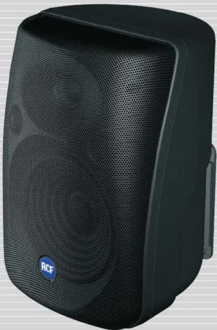
The MQ 50 is a monitor speaker for constant directivity installation. It is a two-way speaker with 5" woofer and waveguide-loaded dome tweeter to ensure intelligibility and correct dispersion of the sound over a wide angle of coverage.
The built-in support makes the MQ 50 easy to install and enables close fitting to the wall, limiting its protrusion.
The exclusive attachment system designed for the MQ 50 model allows the installer to fit the attachment bracket to the wall and make the electrical connections during the pre-installation phase; subsequently, when all the works are completed, the MQ 50 is positioned, oriented, and connected with a simple "click", without the need for tools.
CONNECTIONS
To prevent the risk of electric shock, do not connect the speaker with the amplifier switched on.

Before using the speaker, carefully check that all the connections have been made correctly to make sure there are no accidental short circuits that could cause electrical sparks. The speaker can be connected to constant voltage audio lines at 70 V or 100 V or to constant impedance lines (rotary switch positioned to 16 Ohm).
- Turn the rotary switch (Fig. 1) and select the voltage of the line and the power to be delivered.
- Connect the black conductor of the speaker to the "negative" (-) of the audio line, that leads from the amplifier terminal marked -, 0 or COM tap of the amplifier
- Connect the other conductor of the speaker to the "positive" (+) conductor of the audio line.
-
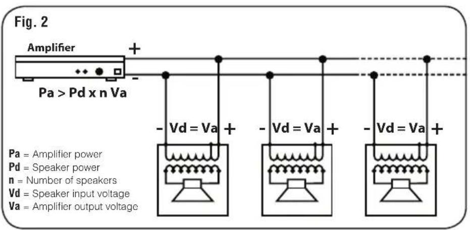
When making the connections, keep the following indications in mind (Fig. 2, costant voltage).
-
The input voltage selected on the speaker must correspond with the voltage selected on the amplifier.
- The sum of the operating power values of all the speakers connected to the audio line must not exceed that of the amplifier.
- To ensure correct audio reproduction, the connections should be made "in phase", where the +/- polarities of the amplifier output correspond with the +/- polarities of the speaker input.
When two speakers reproduce the same frequencies but with phase differences, these frequencies may be annulled. In sound systems, speakers are often situated in adjacent positions and the sound waves produced interact with each other. If a speaker is connected incorrectly; i.e. the polarity of the audio line conductors is inverted, the audio signals are transmitted with differences in phase and correct reproduction is therefore jeopardized.
text_image
Fig. 2 Amplifier + Pa > Pd x n Va -Vd = Va + -Vd = Va + -Vd = Va + Pa = Amplifier power Pd = Speaker power n = Number of speakers Vd = Speaker input voltage Va = Amplifier output voltage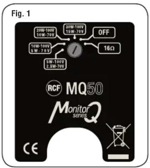
text_image
Fig. 1 20W-100V 16W-70V 30W-100V 15W-70V OFF 16Ω 10W-100V 5W - 70V 5W-100V 2.5W-70V RCF MQ50 Monitor series CEINPUT CABLES
For connecting the speaker use cables with an adequate cross-section. The greater the distance between the amplifier and the speaker, the larger the connection cable cross-section should be to limit the voltage loss along the line.
To prevent inductive phenomena from giving rise to humming or disturbance that jeopardize the effective operation of the audio system, the speaker cables should not be run together with electrical energy conductors, microphone cables, or low level audio lines (e.g. LINE level).
To facilitate the "in phase" connection of the speaker, use bipolar cables that have markings to distinguish the polarity (e.g. insulation of different colours, conductors of different colours, ect.).
To minimize the inductive effects (hum) due to coupling with surrounding electrical fields, use cables with conductors braided together.
You are recommended to install the speaker safety, checking that the fixing surface is resistant and solid enough to support the weight of the speaker, so as to prevent the risk of it falling that could put the safety of persons and structures in jeopardy.
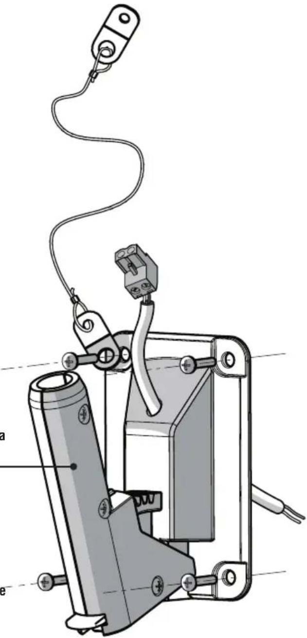
The accessory is installed as follows (see the figure):
Using suitable plugs and screws (not provided), fix the support at the chosen point on the wall. The plugs to be used must be chosen carefully depending on the type of wall plasterboard, hollow bricks, solid bricks, concrete, matchboard panelling, etc.).
text_image
165 245 175
- Insert the cable through the mounting accessory
- Connect the cable to speaker line coming from the amplifier
• Install the wall-mounting accessory by using screws with max. diameter 5 mm (not provided).
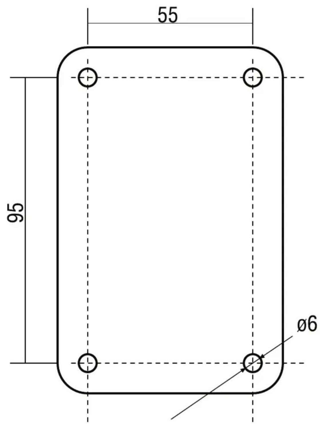
Note: there is a template for drilling at page 13. The provided safety cable is to be fixed to one of the four accessory screws.
text_image
Technical diagram of a mechanical device with labeled parts and wiring, showing components like a, e, and a connector.
natural_image
Technical diagram of a device interior with internal components and a cable, showing no text or symbols.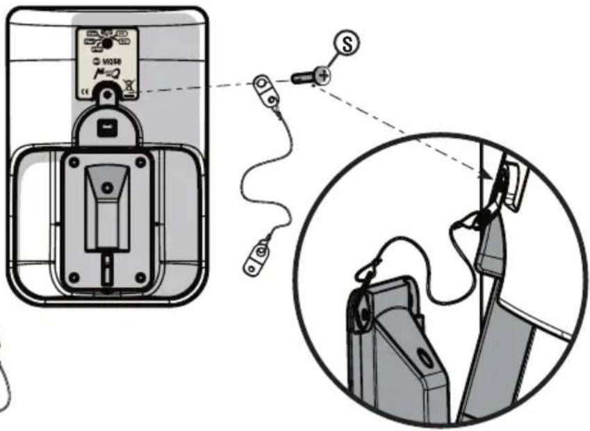
text_image
Diagram showing a device with a switch connected to a power plug, alongside its internal wiring diagram.text_image
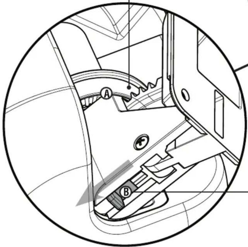
③ Collega ③ Plug-inMake sure the tooth of the ⑤ chosen vertical tilt setting has been properly/deeply inserted into the circular seat A.
text_image
Technical diagram of a mechanical component with labeled parts A and B, showing internal structure and directional arrows.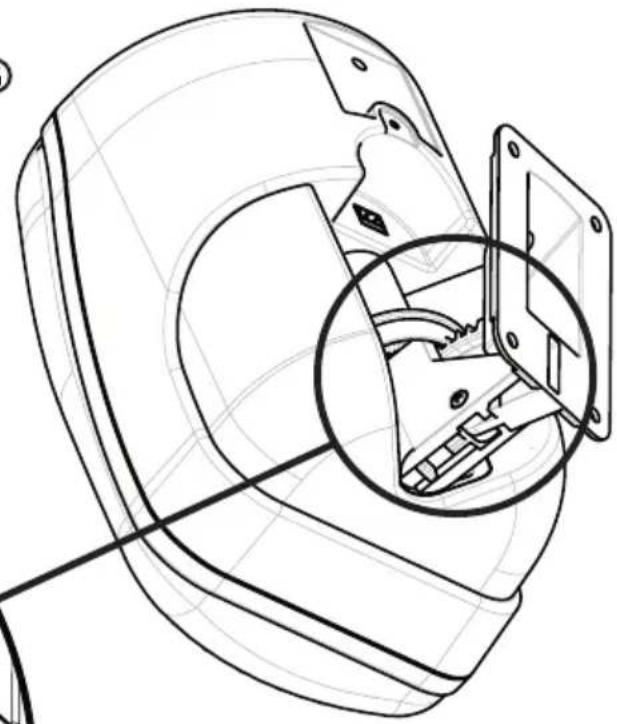
natural_image
Technical line drawing of a mechanical assembly with a magnified inset showing internal components (no text or symbols)⑥ Then block the loudspeaker in the desidered position by moving the lever Ⓑ towards the loudspeaker.
For aiming or removing the loudspeaker, move the lever Ⓑ towards the mounting accessory.
text_image
55 96 96Sensitivity: 89 dB SPI 1W/1m
Frequency response(-10dB): 70 - 20000 Hz
SPL: 110 dB
Power/RMS: 120/60 W Bypass
Constant voltage: 70.7 - 100 V
Impedance: ____ [Bypass] 16 Ohm
Line transformer [100V]: ____ 333 Ω - 30 W, 500 Ω - 20 W, 1 kΩ - 10 W, 2 kΩ - 5 W
[70.7V]: ____ 333 Ω - 15 W, 500 Ω - 10 W,
1 kΩ - 5 W, 2 kΩ - 2.5 W
Crossover frequencies: 4500 Hz
Crossover: 12/12 dB/oct
Angle of coverage: ____ 120° horizontal x 100° vertical
Protezioni: Dynamic on woofer and tweeter
Cabinet: Hi-density polystirene HB grade
Connectors: Euroblock
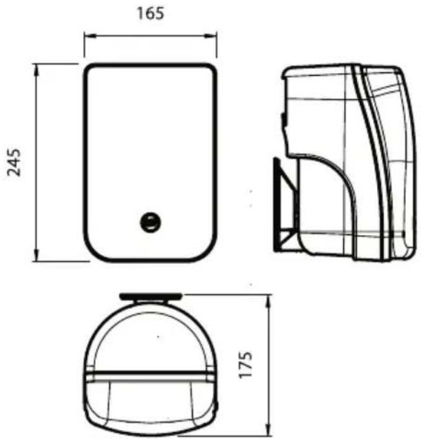
Dimension (L x H x P): 160 x 240 x 130 mm
Colour: anthracite grey / white / silver
Weight: 3 Kg