
A2004NS - Router Totolink - Free user manual and instructions
Find the device manual for free A2004NS Totolink in PDF.


| Product Type | AC1200 Wireless Dual Band Gigabit Router |
| Wireless Standards | IEEE 802.11ac/n/g/b/a |
| Maximum Data Rate | 300 Mbps (2.4 GHz) + 867 Mbps (5 GHz) |
| Antennas | 4 high gain omnidirectional antennas |
| Ethernet Ports | 5 Gigabit Ethernet (1 WAN, 4 LAN) |
| USB Port | 1 USB 2.0 port for storage sharing |
| Wireless Security | WEP, WPA, WPA2, WPA-PSK/WPA2-PSK (TKIP/AES) |
| Advanced Features | WDS, Wireless Multibridge, VPN Server (PPTP), QoS, Port Forwarding, DMZ, DDNS |
| Management | Web interface, SNMP, firmware upgrade, config backup/restore |
| Power Supply | DC 12V, 1A adapter (included) |
Frequently Asked Questions - A2004NS Totolink
User questions about A2004NS Totolink
0 question about this device. Answer the ones you know or ask your own.
Ask a new question about this device
Download the instructions for your Router in PDF format for free! Find your manual A2004NS - Totolink and take your electronic device back in hand. On this page are published all the documents necessary for the use of your device. A2004NS by Totolink.
USER MANUAL A2004NS Totolink
AC1200 Wireless Dual Band Gigabit Router
Model No.: A2004NS
Table of Contents
1. REVISION......4
1.1 Revision History......4
2. ABOUT THIS GUIDE ....5
1.1 Overview of the User's Guide....5
3. INTRODUCTION....5
3.1 Overview....5
3.2 Features 5
3.3 Panel Layout 6
3.3.1 Front Panel 6
3.3.2 Rear Panel 7
3.3.3 Antenna Placement 7
4. HARDWARE INSTALLATION ....8
4.1 Hardware Installation 8
4.2 Check the Installation....8
4.3 Set up the Computer....8
5. CONNECTING TO INTERNET....10
5.1 Login Web Interface.... 10
5.2 Changing Password 12
5.3 Internet Setup.... 12
5.3.1 DHCP User....13
5.3.2 PPPoE User (ADSL) 14
5.3.3 Static IP 14
5.4 Wireless Setup (2.4GHz) 15
5.4.1 Shared Key (WEP) 16
5.4.2 WPA-PSK/WPA2-PSK (Recommended) 16
5.5 Wireless Setup (5GHz) 16
5.6 Firmware Upgrade 17
6. ADVANCED SETUP ....17
6.1 Network 18
6.1.1 Internet Status.... 18
6.1.2 LAN Status....18
6.1.3 Internet Setup 18
6.1.4 LAN/DHCP Server.... 19
6.2 Wireless (2.4GHz) 21
6.2.1 Wireless Status.... 21
6.2.2 Wireless Setup....21
6.2.3 Multiple BSS....22
6.2.4 Wireless Scheduler 22
6.2.5 Wireless Multibridge 23
6.2.6 MAC Authentication .... 24
6.2.7 WDS Setup 25
6.2.8 WPS Setup....26
6.2.9 Advanced Setup....26
6.3 Wireless (5GHz) 29
6.3.1 Wireless Status....29
6.3.2 Wireless Setup 29
6.3.3 Multiple BSS....30
6.3.4 Wireless Scheduler 31
6.3.5 Wireless Multibridge 31
6.3.6 MAC Authentication .... 31
6.3.7 WDS Setup 32
6.3.8 WPS Setup....33
6.3.9 Advanced Setup....33
6.4 NAT/Routing 35
6.4.1 Port Forwarding....35
6.4.2 DMZ / Twin IP 36
6.4.3 Port Trigger 36
6.4.4 Misc Setup....37
6.4.5 Routing Table 37
6.5 Firewall 37
6.5.1 Internet Access Control 38
6.5.2 Net Detector 38
6.5.3 Mgmt Access List....39
6.5.4 Misc Setup....39
6.6 Utility 40
6.6.1 VPN Setup....40
6.6.2 DDNS 41
6.6.3 WOL....41
6.6.4 Host Scan....42
6.6.5 IPTV 43
6.7 Traffic....43
6.7.1 QoS Setup....43
6.7.2 Connection Info....44
6.7.3 Connection Control 44
6.7.4 Wired Port Setup 45
6.8 System 46
6.8.1 System Log....46
6.8.2 Admin Setup....47
6.8.3 SNMP Agent....47
6.8.4 Firmware Upgrade....48
6.8.5 System Time....48
6.8.6 Config Backup/Restore 49
6.8.7 Misc Setup....49
6.9 USB Storage.... 50
6.9.1 Device Mgmt....50
6.9.2 Service Setup....50
6.9.3 Connected User .... 53
Copyright Statement
All the photos and product specifications mentioned in this manual are for references only, as the upgrading of software and hardware. They are subject to change without notice. No part of the specifications may be reproduced in any form or by any means or used to make any derivative such as translation, transformation, or adaptation without permission from TOTOLINK. If you want to know more about our products information, please visit our website at http://www.totolink.net
Copyrights 2014 by TOTOLINK All rights reserved.
1. REVISION
1.1 Revision History
| Version | Amendments | Revision Date |
| V1.0 | Preliminary Document | 2013-03-27 |
| V1.1 | Add Antenna placement, IPTV, SNMP Agent | 2014-01-06 |
2. ABOUT THIS GUIDE
Thank you very much for purchasing TOTOLINK A2004NS Dual Band Gigabit Wireless AC Router. This guide will introduce the features of this device and tell you how to connect, use and configure the router to connect with Internet. Please follow the instructions in this guide to avoid affecting the router's performance by improper operation.
1.1 Overview of the User's Guide
Introduction: Describes the wireless router, the features and appearance.
Hardware Installation: Describes the hardware installation and how to setup PC.
Connecting to Internet: Tells you how to access Internet quickly by the router.
Advanced Settings: Lists all technical functions including Wireless, Network, NAT/Routing, Firewall, Utility, Traffic and System.
3. INTRODUCTION
3.1 Overview
This device is a dual band concurrent wireless AC gigabit router which complies with the next generation WiFi standard - 802.11ac. It allows users to access Internet by DHCP/PPPoE/Static IP and provides maximum speed up to 300Mbps on 2.4GHz and 867Mbps on 5GHz. Since it provides Wireless Multibridge, WDS and VPN Server settings, this router can be also used as Repeater, VPN Server and Wireless AP.
3.2 Features
Complies with IEEE 802.11ac/n/g/b/a standards.
- Advanced MIMO technology enhances the throughput and wireless coverage.
➢ Supports PPPoE, DHCP and Static IP broadband functions.
➢ Provides 64/128-bit WEP, WPA, WPA2 and WPA/WPA2 (TKIP+AES) security.
▶ Equipped with four high gain antennas.
- Provides five Gigabit Ethernet Ports.
➢ Supports universal repeater and WDS function.
- Connects to secure network easily and fast using WPS.
- Provides a multi-functional USB2.0 port.
The IP, MAC and URL filtering makes access and time control more flexible.
The VPN server can not only protect the privacy of your information, but also simplify network management.
3.3 Panel Layout
3.3.1 Front Panel
The front panel of this wireless router consists of 10 LEDs, which is designed to indicate connection status.
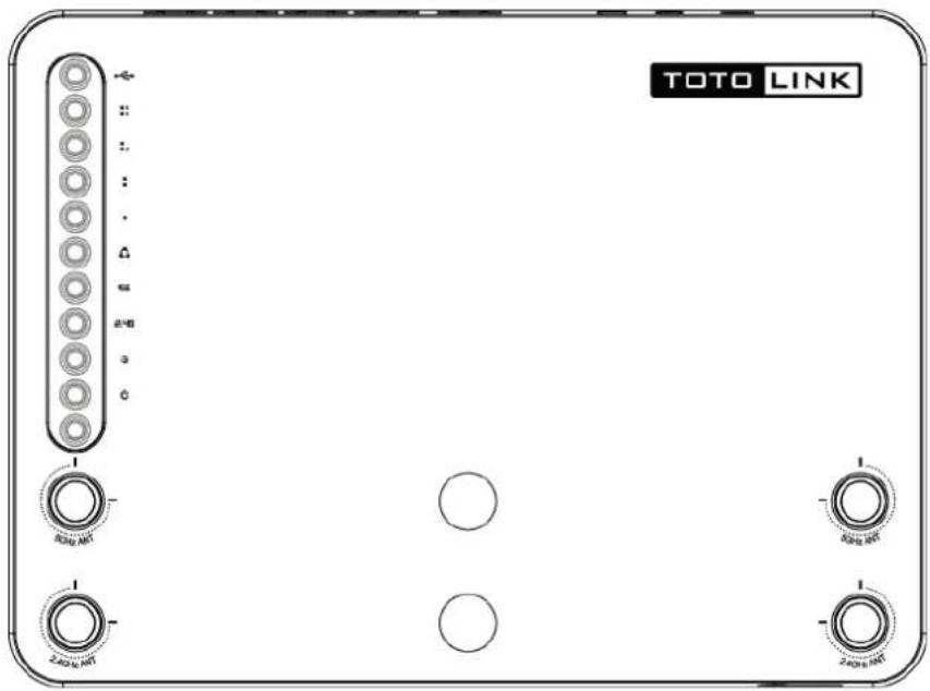
| POWER | This indicator lights blue while the router receiving power, otherwise it is off. |
| CPU | This indicator keeps blinking blue after the router powered on. |
| 2.4G | This indicator lights blue when the router's 2.4G wireless enabled. |
| 5G | This indicator lights blue when the router's 5G wireless enabled. |
| WAN | When the WAN port is connected successfully the indicator lights blue. |
| While transmitting or receiving data through the WAN port the indicator blinks blue. | |
| 1/2/3/4 LAN | When one of the LAN ports has a successful connection, the corresponding indicator lights blue. |
| While transmitting or receiving data through the LAN port the indicator blinks blue. | |
| USB | This indicator lights blue when you have plugged a USB device on the router. |
3.3.2 Rear Panel
The figure below shows the real panel of the router.
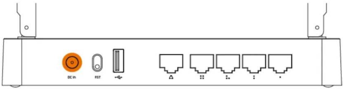
| DC IN | The power socket is used to connect the power adapter. |
| RST | Press the button for about 10 seconds until all the LEDs blink quickly, the device will restore to factory default settings. |
| WAN | This port is used to connect the DSL/cable Modem or Ethernet. |
| 1/2/3/4 LAN | This port connects the router to local PC. |
| USB | The port is provided to plug a USB device for storage sharing |
Note: There is a WPS Button on the other side of the rear panel, press the button for about 2\~3 seconds, it is WPS working.
3.3.3 Antenna Placement
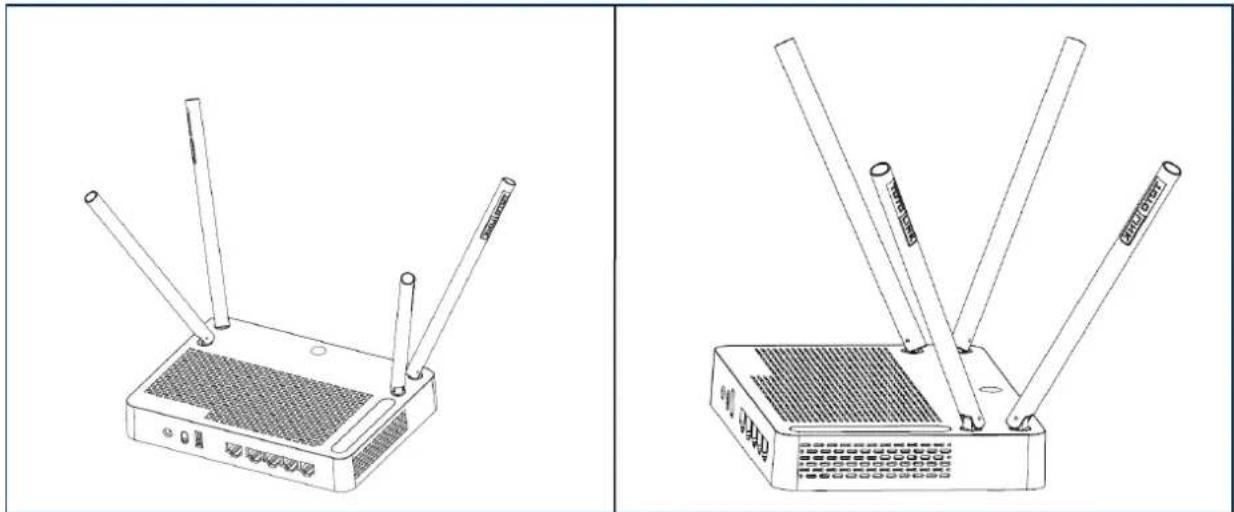
A2004NS's antennas can be rotated to different angles. To avoid signal interference and optimize antenna's performance, you should place the antennas at an angle against the horizontal line and let antennas not be too close to each others. We recommend you orient the antennas as the following illustration shows:
natural_image
Line drawings of a two-wire router with three antennas and ventilation slots (no text or symbols)4. HARDWARE INSTALLATION
4.1 Hardware Installation
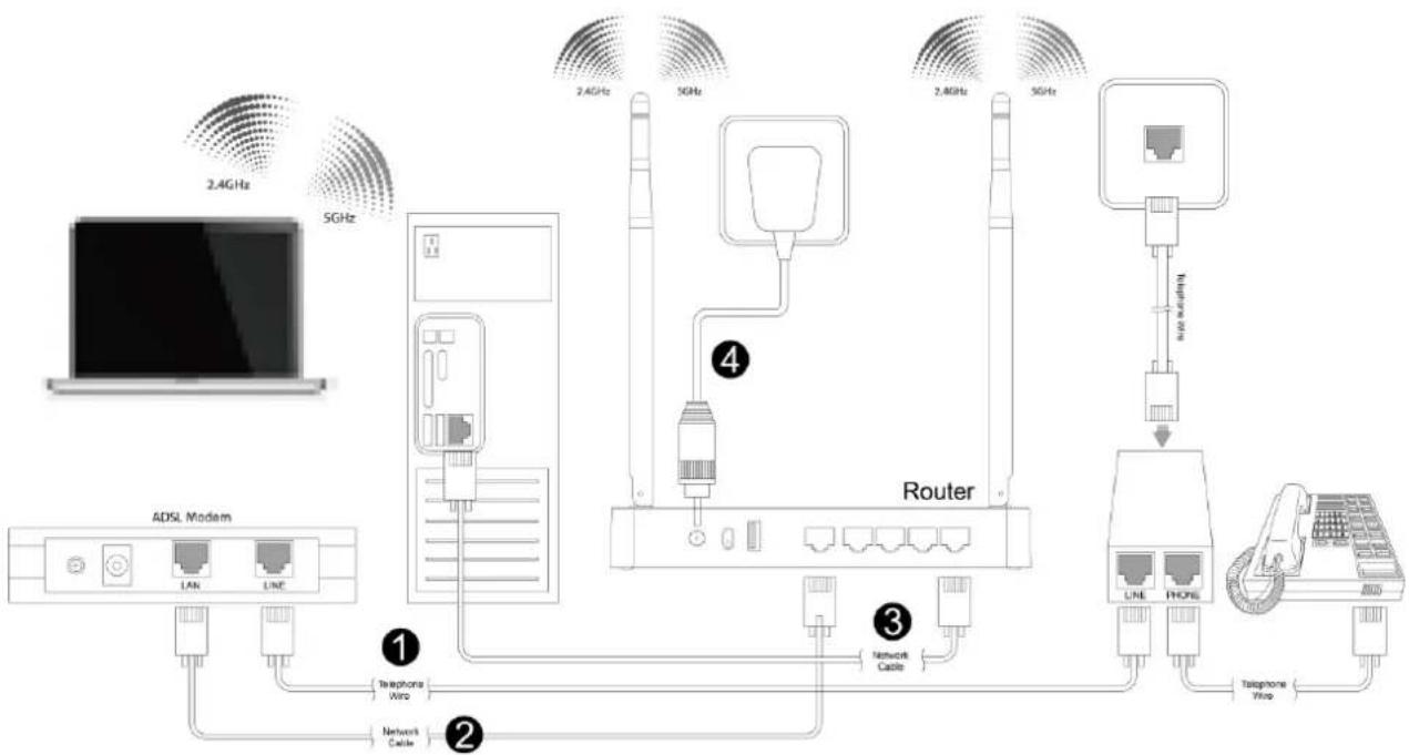
For those PCs you wish to access Internet by this router, each of them must be properly connected with the router through UTP Cables.
Please comply with step 1, 2, 3 and 4 in below diagram in correct order if you access Internet by ADSL, otherwise, please comply with step 2, 3 and 4 to connect to the WAN port of your router with the residential broadband directly.
flowchart
graph TD
    A["ADSL Modem"] -->|1| B["Router"]
    A -->|2| C["2.4GHz"]
    A -->|3| D["2.4GHz"]
    A -->|4| E["5GHz"]
    B --> F["LAN"]
    B --> G["LNE"]
    B --> H["Telephone Wire"]
    B --> I["Network Cable"]
    B --> J["Network Cable"]
    B --> K["Telphone Wire"]
    B --> L["Telephone Wire"]
    B --> M["LNE"]
    B --> N["PHONE"]
    B --> O["Telephone Wire"]
    B --> P["Wireless Connection"]
    style A fill:#f9f,stroke:#333
    style B fill:#ccf,stroke:#333
    style C fill:#cfc,stroke:#333
    style D fill:#fcc,stroke:#333
    style E fill:#cff,stroke:#333
    style F fill:#ffc,stroke:#333
    style G fill:#ffc,stroke:#333
    style H fill:#ffc,stroke:#333
    style I fill:#ffc,stroke:#333
    style J fill:#ffc,stroke:#333
    style K fill:#ffc,stroke:#333
    style L fill:#ffc,stroke:#333
    style M fill:#ffc,stroke:#333
4.2 Check the Installation
The control LEDs of the WLAN Router are clearly visible and the status of the network link can be seen instantly:
- With the power source on, the Power, LAN and WAN LEDs of the WLAN Router will keep lighting blue for a few seconds, the CPU keeps flashing blue.
- About 5 seconds later, only Power, Enabled wireless (2.4G/5G) and the connected LAN LEDs keep lighting, CPU keeps flashing. Other LED is off.
4.3 Set up the Computer
The default IP address of the Router is 192.168.1.1, the default Subnet Mask is 255.255.255.0. Both of these parameters can be changed as you want. In this guide, we will use the default values for description.
Connect the local PC to the LAN port on the Router. There are then two ways to configure the IP address for your PC.
◆ Configure the IP address manually
Configure the network parameters. The IP address is 192.168.1.xxx ("xxx" range from 2 to 254). The Subnet Mask is 255.255.255.0 and Gateway is 192.168.1.1 (Router's default IP address).
♦ Obtain an IP address automatically
Set up the TCP/IP Protocol in Obtain an IP address automatically mode on your PC.
Now, you can run the Ping command in the command prompt to verify the network connection between your PC and the Router. Open a command prompt, and type in ping 192.168.1.1, then press Enter.
C:\Documents and Settings\Administrator>ping 192.168.1.1
Pinging 192.168.1.1 with 32 bytes of data:
Reply from 192.168.1.1: bytes=32 time<1ms TTL=64
Reply from 192.168.1.1: bytes=32 time<1ms TTL=64
Reply from 192.168.1.1: bytes=32 time<1ms TTL=64
Reply from 192.168.1.1: bytes=32 time<1ms TTL=64
Ping statistics for 192.168.1.1:
    Packets: Sent = 4, Received = 4, Lost = 0 (0% loss),
Approximate round trip times in milli-seconds:
    Minimum = 0ms, Maximum = 0ms, Average = 0ms
C:\Documents and Settings\Administrator>.
If the result displayed is similar to that shown in above figure, it means that the connection between your PC and the Router has been established.
C:\Documents and Settings\Administrator>ping 192.168.1.1
Pinging 192.168.1.1 with 32 bytes of data:
Request timed out.
Request timed out.
Request timed out.
Request timed out.

Ping statistics for 192.168.1.1:
    Packets: Sent = 4, Received = 0, Lost = 4 (100% loss),
C:\Documents and Settings\Administrator>
If the result displayed is similar to that shown in the above figure, it means that your PC has not connected to the Router successfully. Please check it following below steps:
1. Is the connection between your PC and the Router correct?
If correct, the LAN port on the Router and LED on your PC's adapter should be lit.
2. Is the TCP/IP configuration for your PC correct?
Since the Router's IP address is 192.168.1.1, your PC's IP address must be within the range of 192.168.1.2 \~ 192.168.1.254, the Gateway must be 192.168.1.1.
5. CONNECTING TO INTERNET
This chapter introduces how to configure the basic functions of your Dual Band Wireless Router so that you can surf Internet.
5.1 Login Web Interface
With a Web-based utility (e.g. Google Chrome), you can quickly enter the setup interface and configure the Router.
Connect to the Router by typing 192.168.1.1 in the address field of Web Browser. Then press Enter key.

It will show up the following page:
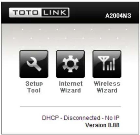
Click Setup Tool icon 📄 to access the Web Interface of the Router. Then below window will pop up that requires you to enter valid User Name and Password.
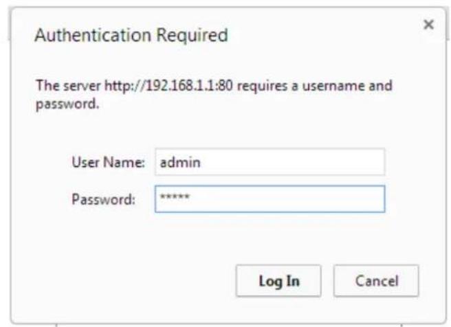
Enter admin for User Name and Password, both in lower case letters. Then click OK button or press Enter.
Note: If the above screen does not prompt, it means that your web-browser has been set to using a proxy. Go to Tools menu>Internet Options>Connections>LAN Settings, in the screen that appears, cancel the Using Proxy checkbox, and click OK to finish it.
Now, you have got into the Router's configuration interface. First, you will see the current status of Router:
![TOTO LINK The Smartest Network Device A2004NS Refresh Save Config Explorer Basic Setup Status Summary Internet Setup Wireless Setup(2.4GHz) Wireless Setup(5GHz) Firmware Upgrade Advanced Setup Status Summary Internet Status Internet(WAN) Port Status WAN port is disconnected Internet Connection Type DHCP User(Dynamic IP) WAN IP Internet connection time 0 Hour 0 Min 0 Sec LAN Configuration LAN IP 192.168.1.1 DHCP Server Status Running DHCP IP Pool 192.168.1.2 - 192.168.1.254 Wireless Status(2.4GHz) Wireless Mode Running - AP Mode - No Encryption SSID(Network Name) TOTOLINK A2004NS 2.4G Wireless Multibridge Stopped Wireless Status(5GHz) Wireless Mode Running - AP Mode - No Encryption SSID(Network Name) TOTOLINK A2004NS 5G Wireless Multibridge Stopped Miscellaneous Firmware Version 8.88 Remote Mgmt Infomation Remote Management is not configured. You can set up this at [Mgmt Access List] page](/content/2026/05/788083/images/cd8fb613cddc753bef4d1b452cb8c67857b42c348de795e85b783d02db9bc946.jpg)
On the left, it is the guide bar:

5.2 Changing Password
Now, we recommend that you change the password to protect the security of your Router. Please go to Advanced Setup—System—Admin Setup change the password required to
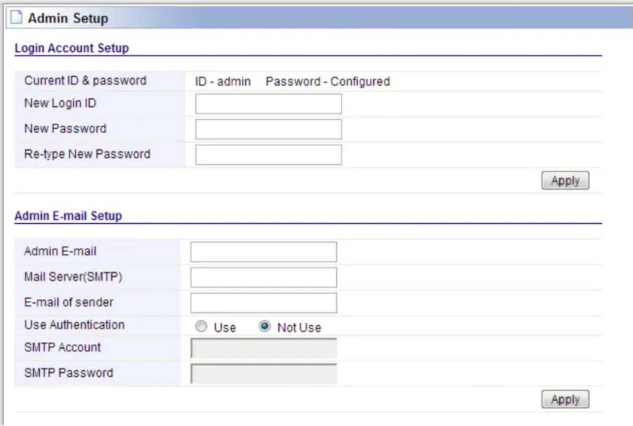
New Login ID: type in the name that you use to login the web interface of the router or change a new one.
New Password: new password is used for administrator authentication.
Re-type New Password: new password should be re-entered to verify its accuracy.
Note: password length is 8 characters maximum, characters after the 8^th position will be truncated.
Admin Email Setup we will discuss later.
5.3 Internet Setup
Click Basic Setup--Internet Setup, this page is used to configure the parameters for Internet Network. WAN access modes include DHCP, PPPoE and Static IP.
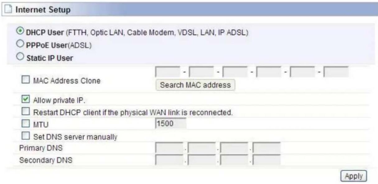
5.3.1 DHCP User
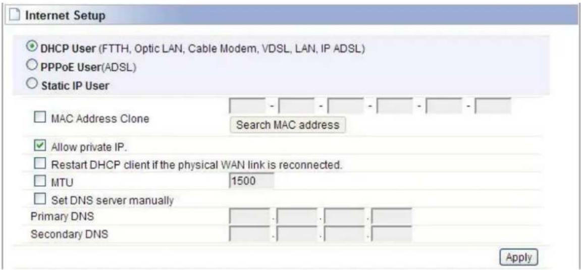
For DHCP User, your computer will get dynamic IP address from your ISP (Internet Service Provider) automatically. No need to do any settings here.
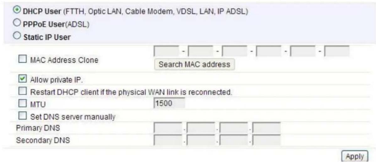
MAC Address Clone: MAC address is the physical address of your computer's network card. Generally, every network card has one unique Mac address. Since many ISPs only allow one computer in LAN to access Internet, users can enable this function to make more computers surf Internet.
MTU: it means Max Transmit Unit for packet. When using slow links, large packets can cause some delays thereby increasing lag and latency.
Set DNS server manually: Domain Name System. Every Internet host must have a unique IP address, also they may have a human-friendly, easy to remember name such as www.yahoo.com. The DNS server converts the user-friendly name into its equivalent IP address.
5.3.2 PPPoE User (ADSL)
If you use ADSL virtual dial-up to connect Internet, please choose this option. Your ISP must have provided the User ID and Password.
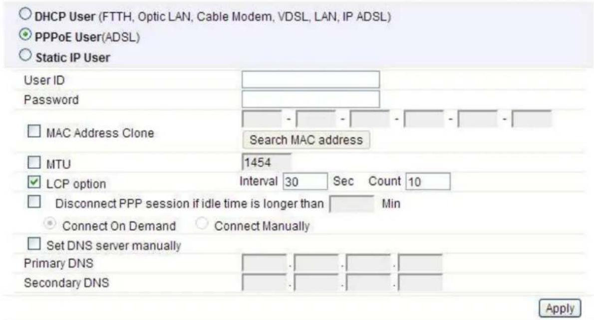
User ID: a specific valid ADSL user name provided by your ISP.
Password: the corresponding valid password provided by your ISP.
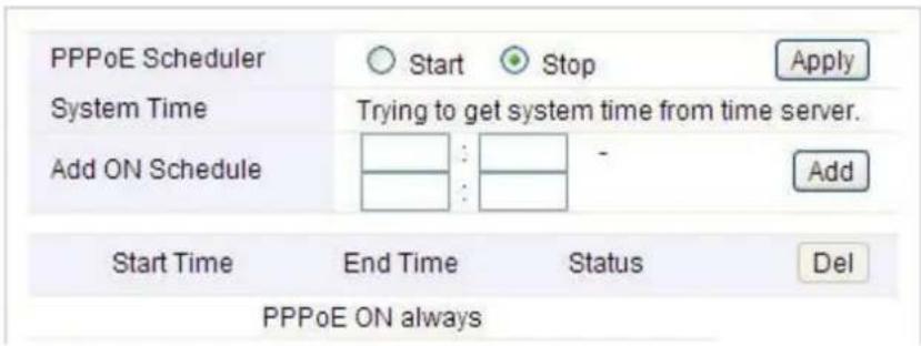
PPPoE Scheduler: when you use PPPoE connection type, you can enable the schedule to set up the time when PPPoE will be on.
Knowledge Extension: Point-to-Point Protocol over Ethernet (PPPoE) is a virtual private and secure connection between two systems that enables encapsulated data transport. It replies on two widely accepted standards: PPP and Ethernet. It connects users through an Ethernet to the Internet with a common broadband medium, such as wireless device or cable modem. All the users over the Ethernet can share a common connection.
5.3.3 Static IP
If your ISP provides a static IP to access Internet, please finish the below parameter settings.
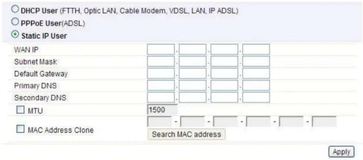
WAN IP: the IP address provided by your ISP.
Subnet Mask: This is used to define the device IP classification for the chosen IP address range. 255.255.255.0 is a typical net mask value for Class C networks. Generally it is provided by your ISP.
Default Gateway: This is the IP address of the host router that resides on the external network and provides the point of connection to the next hop towards the Internet. This can be a DSL modem, Cable modem, or a WISP gateway router. The router will direct all the packets to the gateway if the destination host is not within the local network.
Primary DNS: Domain Name System. Every Internet host must have a unique IP address, also they may have a human-friendly, easy to remember name such as www.yahoo.com. The DNS server converts the user-friendly name into its equivalent IP address. This is provided by your ISP.
After you finish the blank that required, you could click Apply to make all the settings work.
5.4 Wireless Setup (2.4GHz)
This page is used to configure basic wireless parameters and encryption methods.
![2.4GHz Wireless Setup Operation Start Stop SSID TOTOLINK A2004NS 2.4G Channel 5 [ 2.432 GHz,Upper ] Channel Search SSID Broadcast ON OFF Authentication Automatic Encryption Disable WEP64 WEP128 TKIP AES TKIP/AES Apply](/content/2026/05/788083/images/09beb1ea8a9836cc8713753de68f7507c435da3f8e6d62fb1e5b55bf5b632eeb.jpg)
Operation: choose Start to enable your 2.4G wireless network to access Internet wirelessly.
SSID: This is your wireless network name. Others can access Internet wirelessly by search for this SSID and connecting to it.
Channel: Choose the best wireless channel by clicking Channel Search. By default, it is the best channel.
SSID Broadcast: This option is used to hide your SSID.
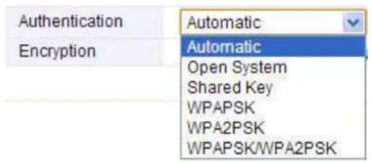
Authentication: You can choose one encryption method for your wireless network.
5.4.1 Shared Key (WEP)
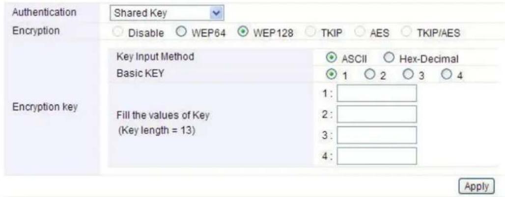
WEP (Wired Equivalent Privacy) is based on the IEEE 802.11 standard and uses the RC4 encryption algorithm. Enabling WEP allows you to increase security by encryption data being transferred over your wireless network. WEP is the oldest security algorithm, and there are few applications that can decrypt the WEP key in less than 10 minutes.
5.4.2 WPA-PSK/WPA2-PSK (Recommended)
Wi-Fi Protected Access (WPA) is the most dominating security mechanism in industry. It is separated into two categories: WPA-personal or called WPA Pre-Share Key (WPA/PSK), and WPA-Enterprise or called WPA/802.1x. WPA2 means Wi-Fi Protected Access 2, it is the current most secure method of wireless security and required for 802.11n performance. Please set one Encryption key (password) for your wireless network to prevent being occupied by others.

5.5 Wireless Setup (5GHz)
This setting is similar to 2.4GHz, but the Mode and Channel are different. You can just keep the default settings.
![5GHz Wireless Setup Operation Start Stop SSID TOTOLINK A2004NS 5G Channel 36 [ 5.180 GHz ] Channel Search SSID Broadcast ON OFF Authentication Automatic Encryption Disable WEP64 WEP128 TKIP AES TKIP/AES Apply](/content/2026/05/788083/images/b297e212bb63caa9ce13bc9f7678a7163b288ad1b9f61383e95e6bb6c4a8394e.jpg)
Operation: choose Start to enable your 2.4G wireless network to access Internet wirelessly. SSID: This is your wireless network name. If you want to access Internet wirelessly, search for this SSID and connect to it. You can define it as you like.
Channel: Choose the best wireless channel by clicking Channel Search. By default, it is the best channel.
SSID Broadcast: This option is used to hide your SSID.
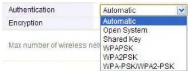
Authentication: You can choose one encryption method for your wireless network, just refer to the configuration on 2.4GHz band.
5.6 Firmware Upgrade
New version of firmware will be released to improve the various efficiency or to fix some bugs. This page allows you to upgrade the Access Point firmware to new version. Click Choose File button to select the firmware version you want to upgrade and then click Upgrade button.
Please Note: DO NOT power off the device during the uploading process because it may damage your system.
![Firmware Upgrade Firmware Version 8.88 Build Date Tue Dec 24 16:00:51 KST 2013 To upgrade manually - Click [Browse] and choose a downloaded firmware - Click [Upgrade] button. Choose File No file chosen Upgrade Note. • Internet will be unavailable for upgrading firmware. • Power down for updating firmware can be the cause of system halt.](/content/2026/05/788083/images/501019874912a64704144c52c815cd159292752d3c6d09889fb15da08ff78c96.jpg)
After finishing the settings above, you'd better restart your computer and the Router to connect to Internet successfully. Then you can enjoy the high-speed and high-stability Internet through this router.
6. ADVANCED SETUP
The Advanced Setup includes Network, Wireless (2.4G & 5G), NAT/Routing, Firewall, Utility, Traffic, System and USB Storage. Most of these settings are only for more technically advanced users who have sufficient knowledge about wireless LAN. Also they should not be changed unless you
know what effect the changes will have on your Wireless Router.
6.1 Network
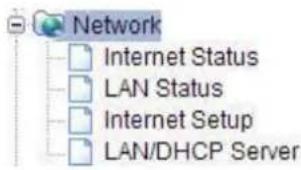
Click the plus sign beside Network menu to show up all Network parameters you could set up.
6.1.1 Internet Status
This page shows the WAN Status of this Router

6.1.2 LAN Status
This page shows you LAN Status of your Router.
| LAN Configuration | |||
| LAN IP | 192.168.1.1 | ||
| Subnet Mask | 255.255.255.0 | ||
| MAC Address | 78-44-76-00-00-08 | ||
| DHCP IP Pool | 192.168.1.2 ~ 192.168.1.254 | ||
| # of allocated IP | 2 | ||
| Allocated IP list | |||
| IP | MAC Address | IP info. | |
| 1 | 192.168.1.2 (Lenovo-PC) | 00-0E-E8-00-00-35 | Wired |
| 2 | 192.168.1.3 (qe-cd15ccd5f60d) | 00-26-66-07-96-41 | Wired |
6.1.3 Internet Setup
We have discussed this setting on Internet Setup. You can also reconfigure the parameters on this page.
6.1.4 LAN/DHCP Server
Click LAN/DHCP Server, you will enter the page that allows you configure the LAN port and DHCP Server.
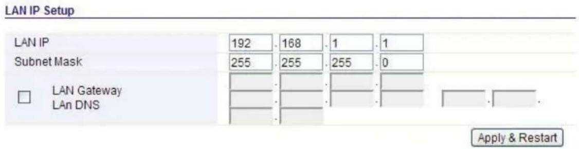
LAN IP: This is the IP address to be represented by the LAN (including WLAN) interface that is connected to the internal network. This IP will be used for the routing of the internal network (it will be the Gateway IP for all the devices connected on the internal network).
Subnet Mask: This is used to define the device IP classification for the chosen IP address range. 255.255.255.0 is a typical subnet mask value for Class C networks which support IP address range from 192.0.0.x to 223.255.255.x. Class C network subnet mask uses 24 bits to identify the network and 8 bits to identify the host.
Note: If the IP address changed, you can log into the WEB configuration interface only using the new IP address.
DHCP Server Setup
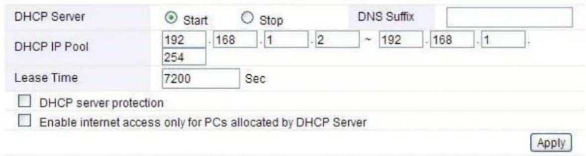
DHCP Server: you can choose to start or stop DHCP.
DHCP IP Pool: it is the IP range that the DHCP server will assign to every PC connected with the router.
Lease Time: the IP addresses given out by the DHCP server will only be valid for the duration specified by the lease time. Increasing the time ensure client operation without interrupt, but could introduce potential conflicts. Lowering the lease time will avoid potential address conflicts, but might cause more slight interruptions to the client while it will acquire new IP addresses from the DHCP server. The time is expressed in seconds.
DHCP Static Lease Setup
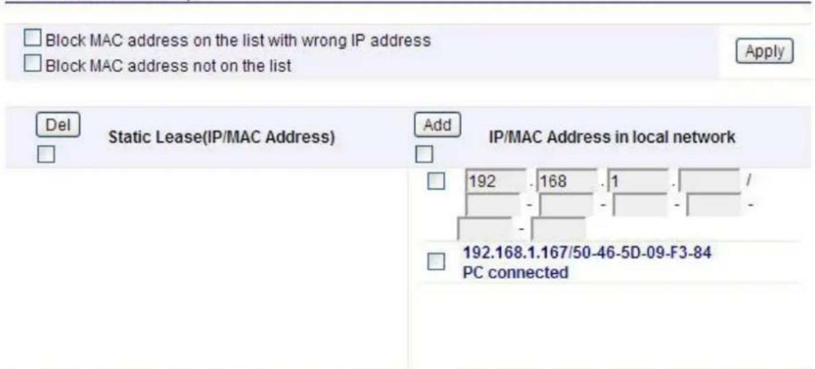
The maximum number of registered MAC Addresses is 200.
Block MAC address on the list with wrong IP address: The PC'S MAC address has existed on the rule but with the wrong IP can't connect to Internet.
Block MAC address not on the list: The PC's MAC address isn't exists on the rule can't connect to Internet.
Static Lease (IP/MAC Address):
Static Lease function allows you reserve IP addresses, and assign the same IP address to the network device with the specified MAC address any time it requests an IP address. This is almost the same as when a device has a static IP address except that the device must still request an IP address from the DHCP server. You can enable or disable this function.
6.2 Wireless (2.4GHz)
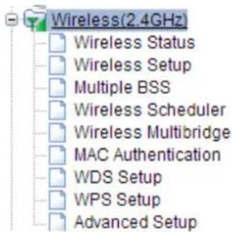
Next, you can set up the Wireless parameters. Click the plus sign beside Wireless (2.4G) menu to open up all wireless parameters, see below figure:
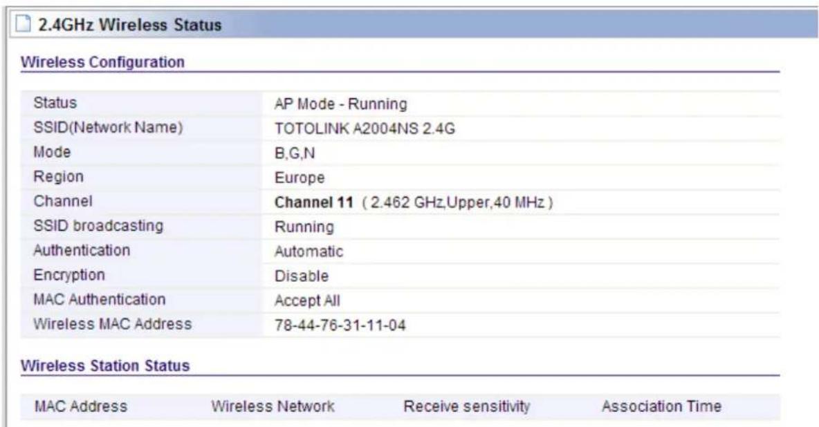
6.2.1 Wireless Status
This page shows you the current wireless status of the router.
6.2.2 Wireless Setup
Click Wireless Setup, you will be able to configure the basic wireless function. We have discussed this setting on Wireless Setup (2.4GHz).
![2.4GHz Wireless Setup Operation Start Stop SSID TOTOLINK A2004NS 2.4G Channel 11 [ 2.462 GHz,Upper ] Channel Search SSID Broadcast ON OFF Authentication Automatic Encryption Disable WEP64 WEP128 TKIP AES TKIP/AES Apply](/content/2026/05/788083/images/de87b9bb11fd8b3eca7a17a4a93da934ec9068f0346efd95d7c4c530a5ae7650.jpg)
6.2.3 Multiple BSS
This page is used to create multiple SSID for different LANs.

SSID: define the SSID by yourself.
Access Policy: setup the access policy as you want.
SSID Broadcast: choose to hide or broadcast your SSID.
WMM: it is an abbreviation of Wi-Fi Multimedia. It defines the priority levels for four access categories derived from 802.1d (prioritization tabs). The categories are designed with specific types of traffic, voice, video, best effort and low priority data.
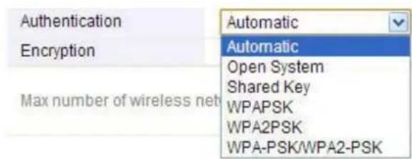
Encryption: you can choose the encryption method for WMM. Please refer to Wireless Setup (2.4G).
6.2.4 Wireless Scheduler
Control the 2.4GHz wireless-on/off time is helpful for you to restrict Internet access to certain hours so that users can connect to the Internet only during certain hours. You have to set your time in System Time section before setting schedule.
![2.4GHz Wireless Scheduler Wireless Scheduler Start Wireless ON in the schedule. Stop Apply Everyday Sun Mon Tue Wed Thu Fri Sat [day - Start Time] 24 hour : - : Schedule Add Del](/content/2026/05/788083/images/90109ae79023f195f695a251f223ddb3589af9e3d4f41272c2316b1b8d33d60c.jpg)
Choose Start and select Wireless ON in the schedule or Wireless OFF in the schedule. For example, the setting as the following picture results in that wireless will be on weekday from eight to eighteen.
![2.4GHz Wireless Scheduler Wireless Scheduler Start Wireless ON in the schedule. Apply Everyday Sun Mon Tue Wed Thu Fri Sat [day - Start Time] 24 hour 8 : 00 - 18 : 00 Schedule Add Del](/content/2026/05/788083/images/c2de3c90f7373896cd3012cf498f0b12c554a9046c083ccd080adbc292bc5e57.jpg)
After clicked Add the schedule will appear on the list and you can also modify the settings after selecting it.
![2.4GHz Wireless Scheduler Wireless Scheduler Start Wireless OFF in the schedule. Apply Everyday Sun Mon Tue Wed Thu Fri Sat [day - Start Time] 24 hour 08 : 00 - 18 : 00 Modify Cancel Schedule Mon Tue Wed Thu Fri / 08:00 - 18:00 Del](/content/2026/05/788083/images/fa9f7cb12325b70f2a43bacc2b229fe3637292c997015010ec22c5db1400e036.jpg)
6.2.5 Wireless Multibridge
This page is used to setup the bridge and repeater functions.
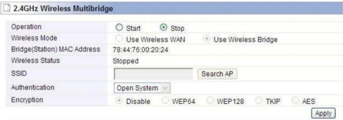
Wireless Bridge: In this mode, the router is used as an AP to get other router's signal.
Wireless WAN: The same function as Wireless Bridge, but the only setting difference is that Wireless WAN need not to stop the DHCP Server.
SSID: Click Search AP; choose the SSID of your Primary Router and then enter the encryption key of the upper AP if the encryption is enabled.
![Wireless network with security (WPA) TOTOLINK A104NS 2.4G (Channel 11 [2.462 GHz, Upper, 40MHz] - 78-44-76-00-20-40) Wireless network without security Signal power - 24% TOTOLINK_b4b745 (Channel 9 - 78-44-76-B4-B7-42) Wireless network with security (WPA2) Signal power - 64% zion (Channel 9 - 00-0E-E8-64-07-56) Wireless network with security (WPA) Signal power - 50% zion (Channel 9 - B8-55-10-C2-82-0C) Signal power - 22% Double click a AP row or click 'Select AP' button Resan AP Select AP](/content/2026/05/788083/images/dbd2ee9183567c9d4d648003de9b4e2599e8c91cff616537da138d1b1d184539.jpg)
Note: Both these two repeater methods can help you to expand the wireless coverage and allow more terminals to access Internet. But since Wireless WAN need not stop DHCP Server, all PCs' IP Addresses are assigned by the Secondary Router itself. So this method allows more PCs to access Internet than Wireless Bridge. In Wireless Bridge mode, the PCs' permissions to access Internet are decided by Primary Router which can make users to manage the LAN more easily.
6.2.6 MAC Authentication
You can control the PC to connect the wireless Router through MAC authentication.

2.4GHz MAC Authentication
Select wireless network
TOTOLINK A2004NS 2.4G

Accept All

Accept MAC address registered

Reject MAC address registered
Apply
Del
Registered MAC address list
Add
MAC address List in wireless
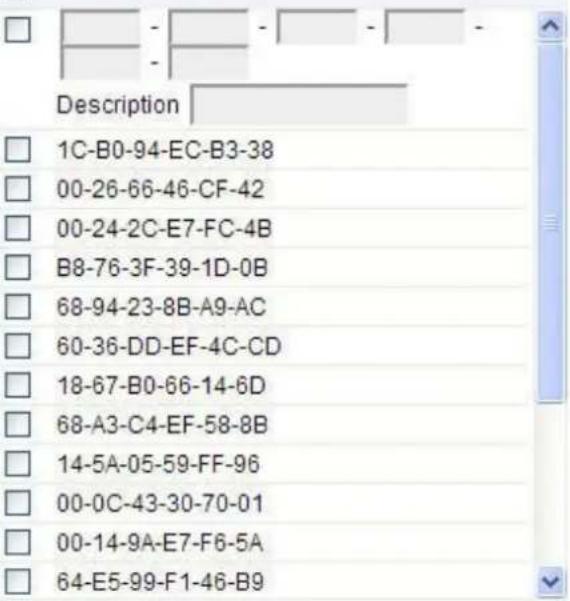
The maximum number of registered MAC Addresses is 128.
6.2.7 WDS Setup
WDS means Wireless Distribution System. It is a protocol for connecting two access points wirelessly. Usually, it can be used for the following application:
- Provide bridge traffic between two LANs though the air.
- Extend the coverage range of a WLAN.
To meet the above requirement, you must set these APs in the same channel and set MAC address of other APs which you want to communicate with in the table and then enable the WDS.
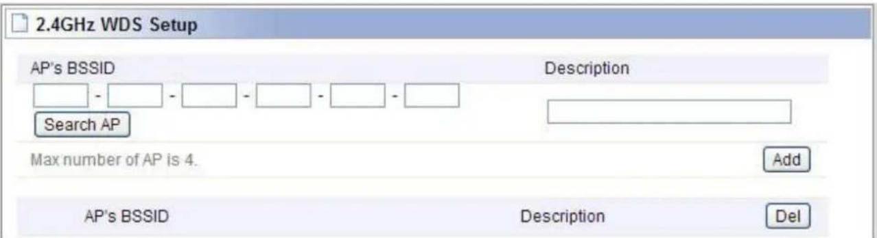
6.2.8 WPS Setup
WPS (Wi-Fi Protected Setup) provides easy procedure to make network connection between wireless station and wireless access point with the encryption of WPA and WPA2. It is enabled by default.
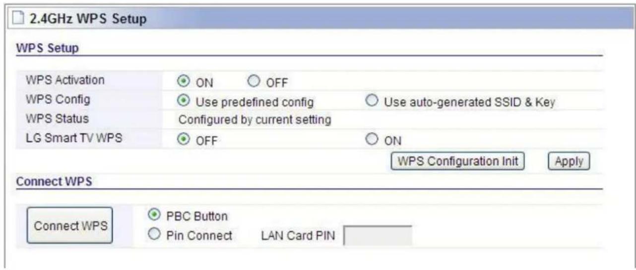
6.2.9 Advanced Setup
Advanced Setup is for advanced parameter settings. For common users, please just keep the default configuration. If you want to change these parameters, please choose the item at first and then you can modify it in the lower part of the page.
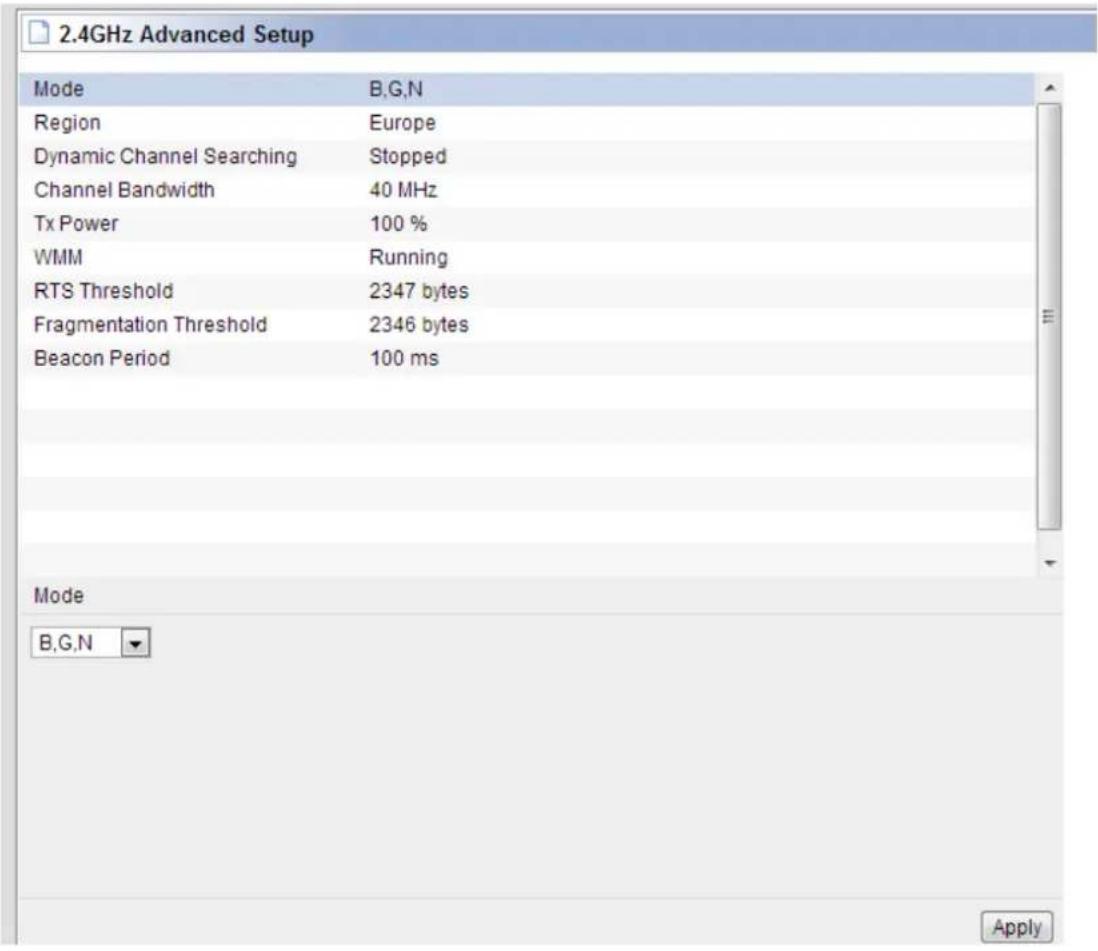
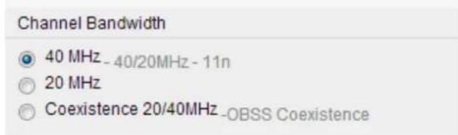
Channel Bandwidth: this is the spectral width of the radio channel. When there are 11N wireless clients you can choose 40MHz or coexistence 20/40 frequency band; when there are 11b/g wireless clients, please choose 20MHz.
TX Power: please refer to the description on the page.
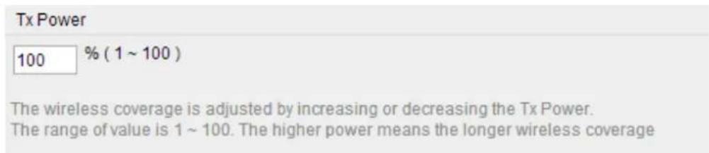
WMM: It is an abbreviation of Wi-Fi Multimedia. It defines the priority levels for four access categories derived from 802.1d (prioritization tabs). The categories are designed with specific types of traffic, voice, video, best effort and low priority data. Choose ON/OFF to enable/disable this function.
WMM

ON

OFF
RTS Threshold: determines the packet size of a transmission and, through the use of an access point, helps control traffic flow. The range is 0-2347 bytes. The default value is 2347, which means that RTS is disabled.
RTS/CTS (Request to Send / Clear to send) are the mechanism used by the 802.11 wireless networking protocols to reduce frame collisions introduced by the hidden terminal problem. RTS/CTS packet size threshold is 0-2347 bytes. If the packet size the node wants to transmit is larger than the threshold, the RTS/CTS handshake gets triggered. If the packet size is equal to or less than threshold the data frame gets sent immediately.
System uses Request to Send/Clear to send frames for the handshake that provide collision reduction for an access point with hidden stations. The stations are sending a RTS frame first while data is sent only after a handshake with an AP is completed. Stations respond with the CTS frame to the RTS, which provide clear media for the requesting station to send the data. CTS collision control management has a time interval defined during which all the other stations hold off the transmission and wait until the requesting station will finish transmission.
RTS Threshold
2347 bytes
The frames which have more length than RTS threshold are transmitted using RTS/CTS method. The less RTS threshold make wireless communication be more stable, but have less maximum throughput. The valid range is 1 \~ 2347.
Fragment Threshold: specifies the maximum size for a packet before data is fragmented into multiple packets. The range is 256-2346 bytes. Setting the Fragment Threshold too low may result in poor network performance. The use of fragment can increase the reliability of frame transmissions. Because of sending smaller frames, collisions are much less likely to occur. However, lower values of the Fragment Threshold will result in lower throughput as well. Minor or no modifications of the Fragmentation Threshold value is recommended while default setting of 2346 is optimum in most of the wireless network use cases.
Fragmentation Threshold
2346
bytes
The frames which have more length than fragmentation threshold are transmitted after fragmented with setting value The less Fragmentation Threshold may make wireless communication more stable, but have less maximum throughput. The valid range is 256 \~ 2346.
Beacon Period: By default, it is set to 100ms. Higher Beacon interval will improve the device's wireless performance and is also power-saving for client side. If this value set lower than 100ms, it will speed up the wireless client connection.
Beacon Period
100
ms
Normally use 100ms
The range should be from 50ms to 1024ms.
6.3 Wireless (5GHz)
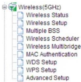
Wireless (5GHz) is provided to enable users to establish 5G wireless channel connection, which can provide high performance for HD video streaming and online gaming. All the parameter settings please refer to Wireless (2.4GHz).
6.3.1 Wireless Status
This page shows you the current wireless status of the router.
5GHz Wireless Status
Wireless Configuration
| Status | AP Mode - Running |
| SSID(Network Name) | TOTOLINK A2004NS 5G |
| Mode | 11ac/11n 5GHz |
| Region | Europe |
| Channel | Channel 36 (5.180 GHz,80 MHz) |
| SSID broadcasting | Running |
| Authentication | Automatic |
| Encryption | Disable |
| MAC Authentication | Accept All |
| Wireless MAC Address | 78-44-76-31-11-00 |
Wireless Station Status
| MAC Address | Wireless Network | Receive sensitivity | Association Time | |
| 1 | 78-44-76-B6-61-F9 | TOTOLINK... | 56% | 4 Min 44 Sec |
6.3.2 Wireless Setup
Click Wireless Setup, you will be able to configure the basic wireless function. We have discussed this setting on Wireless Setup (5GHz).
![5GHz Wireless Setup Operation Start Stop SSID TOTOLINK A2004NS 5G Channel 36 [5.180 GHz] Channel Search SSID Broadcast ON OFF Authentication Automatic Encryption Disable WEP64 WEP128 TKIP AES TKIP/AES Apply](/content/2026/05/788083/images/0c5b4a0b381a043d405d1455264292534b352808d8a61881ba86a4e2eef67637.jpg)
6.3.3 Multiple BSS
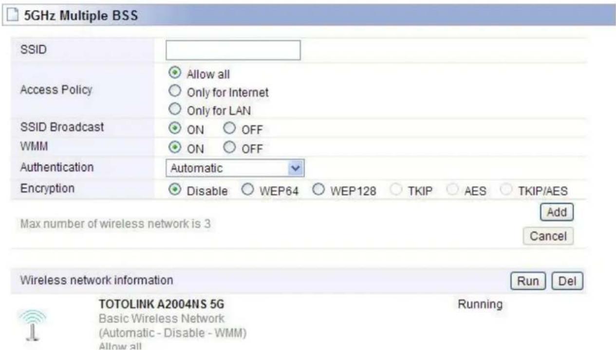
This page is used to create multiple SSID for different LANs.
SSID: define the SSID by yourself.
Access Policy: setup the access policy as you want.
SSID Broadcast: choose to hide or broadcast your SSID.
WMM: it is an abbreviation of Wi-Fi Multimedia. It defines the priority levels for four access categories derived from 802.1d (prioritization tabs). The categories are designed with specific types of traffic, voice, video, best effort and low priority data.
Encryption: you can choose the encryption method for WMM. Please refer to Wireless Setup (5G).
6.3.4 Wireless Scheduler
The setting to control the 5GHz wireless-on/off time is similar with 2.4GHz wireless scheduler. Please set your time in System Time section before setting schedule.
![5GHz Wireless Scheduler Wireless Scheduler Start Wireless ON in the schedule. Apply Stop Everyday Sun Mon Tue Wed Thu Fri Sat [day - Start Time] 24 hour : - : Schedule Add Del](/content/2026/05/788083/images/9c433324f7b475e605a34bccc28b1749dd094354574003f18fe17784927cf61c.jpg)
6.3.5 Wireless Multibridge
This page is used to setup the bridge and repeater functions.
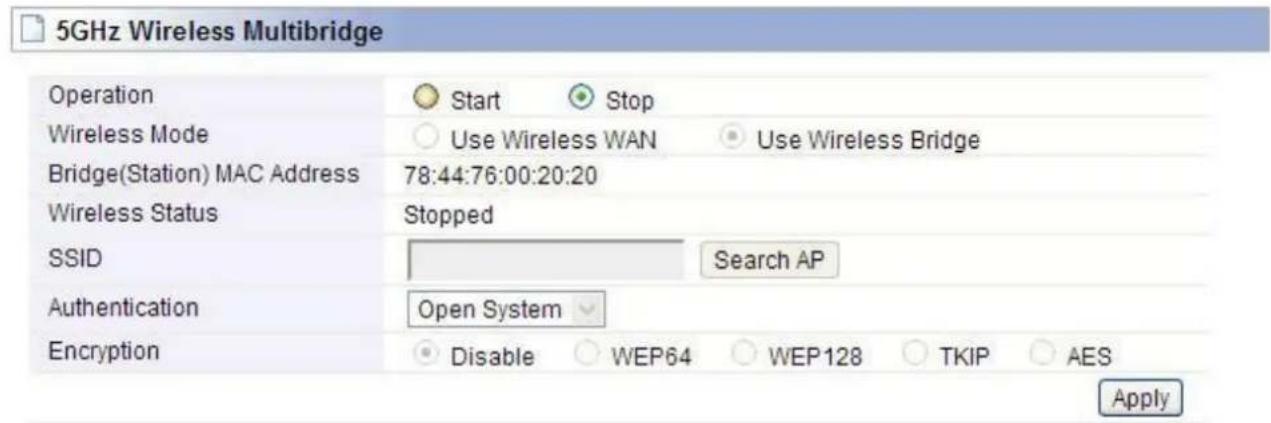
Wireless Bridge: In this mode, the router is used as an AP to get other router's signal.
Wireless WAN: The same function as Wireless Bridge, but the only setting difference is that Wireless WAN need not to stop the DHCP Server.
SSID: Click Search AP; choose the SSID of your Primary Router and enter the encryption key if the encryption is enabled.
Note: Both these two repeater methods can help you to expand the wireless coverage and allow more terminals to access Internet. But since Wireless WAN need not stop DHCP Server, all PCs' IP Addresses are assigned by the Secondary Router itself. So this method allows more PCs to access Internet than Wireless Bridge. In Wireless Bridge mode, the PCs' permissions to access Internet are decided by Primary Router which can make users to manage the LAN more easily.
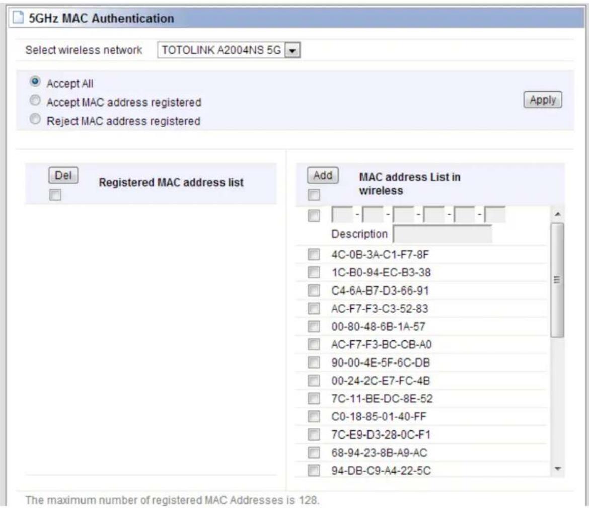
6.3.6 MAC Authentication
You can control the PC to connect the wireless Router through MAC authentication.
6.3.7 WDS Setup
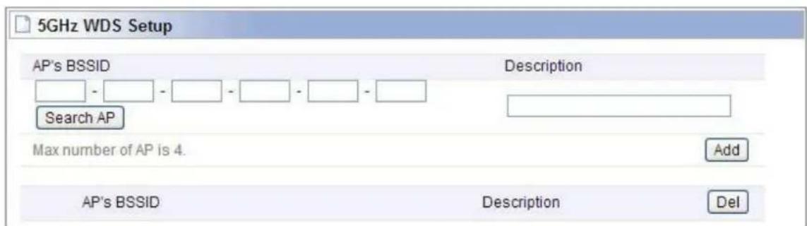
WDS means Wireless Distribution System. It is a protocol for connecting two access points wirelessly. Usually, it can be used for the following application:
-
Provide bridge traffic between two LANs though the air.
-
Extend the coverage range of a WLAN.
To meet the above requirement, you must set these APs in the same channel and set MAC address of other APs which you want to communicate with in the table and then enable the WDS.
6.3.8 WPS Setup
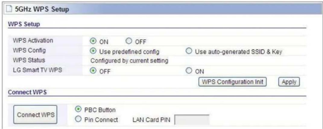
WPS (Wi-Fi Protected Setup) provides easy procedure to make network connection between wireless station and wireless access point with the encryption of WPA and WPA2. It is enabled by default.
6.3.9 Advanced Setup
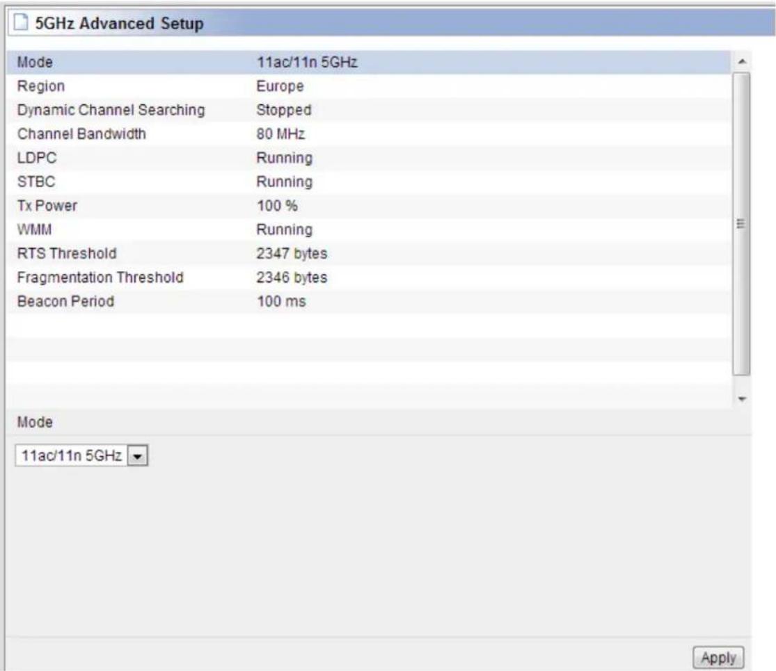
Advanced Setup is for advanced parameter settings. For common users, please just keep the default configuration.
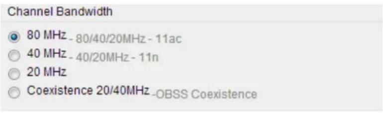
Channel Bandwidth: this is the spectral width of the radio channel. 80MHz is recommended for better throughput. When there are 11AC wireless client, please select the 80MHz frequency band; when there are 11N wireless clients you can choose 40MHz or coexistence 20/40 frequency band; when there are 11b/g wireless clients, please choose 20MHz.
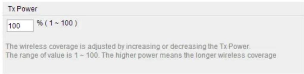
TX Power: please refer to the description on the page.
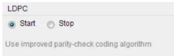
LDPC: Low Density Parity Check Codes are a class of recently re-discovered highly efficient linear block codes. LDPC codes are finding increasing use in applications requiring reliable and highly efficient information transfer over bandwidth or return channel-constrained links in the presence of corrupting noise.
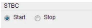
STBC: Space–time block coding is a technique used in wireless communications to transmit multiple copies of a data stream across a number of antennas and to exploit the various received versions of the data to improve the reliability of data-transfer.
RTS Threshold: determines the packet size of a transmission and, through the use of an access point, helps control traffic flow. The range is 0-2347 bytes. The default value is 2347, which means that RTS is disabled.
RTS/CTS (Request to Send / Clear to send) are the mechanism used by the 802.11 wireless networking protocols to reduce frame collisions introduced by the hidden terminal problem. RTS/CTS packet size threshold is 0-2347 bytes. If the packet size the node wants to transmit is larger than the threshold, the RTS/CTS handshake gets triggered. If the packet size is equal to or less than threshold the data frame gets sent immediately.
System uses Request to Send/Clear to send frames for the handshake that provide collision
reduction for an access point with hidden stations. The stations are sending a RTS frame first while data is sent only after a handshake with an AP is completed. Stations respond with the CTS frame to the RTS, which provide clear media for the requesting station to send the data. CTS collision control management has a time interval defined during which all the other stations hold off the transmission and wait until the requesting station will finish transmission.
Fragment Threshold: specifies the maximum size for a packet before data is fragmented into multiple packets. The range is 256-2346 bytes. Setting the Fragment Threshold too low may result in poor network performance. The use of fragment can increase the reliability of frame transmissions. Because of sending smaller frames, collisions are much less likely to occur. However, lower values of the Fragment Threshold will result in lower throughput as well. Minor or no modifications of the Fragmentation Threshold value is recommended while default setting of 2346 is optimum in most of the wireless network use cases.
Beacon Period: By default, it is set to 100ms. Higher Beacon interval will improve the device's wireless performance and is also power-saving for client side. If this value set lower than 100ms, it will speed up the wireless client connection.
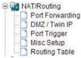
6.4 NAT/Routing
Click the plus sign beside NAT/Routing menu to open us all the parameters contained, see below:
6.4.1 Port Forwarding
On this page, you can redirect common network services automatically to a specific device behind the NAT firewall. This setting is only necessary when you want to host some sort of servers like a Web server or mail server on the private local network behind your Gateway's NAT firewall.
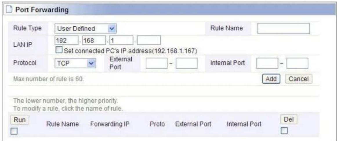
LAN IP: You can set the IP Address that you defined the rule for.
Protocol: Choose which particular protocol type should be forwarding. Here you can choose UDP/TCP.
External Port: Set the WAN range.
Internal Port: Set the LAN range.
6.4.2 DMZ / Twin IP
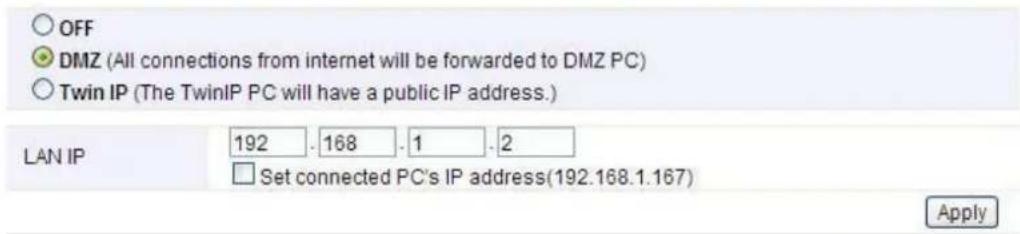
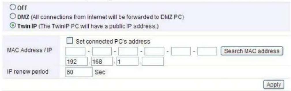
The DMZ (Demilitarized Zone) host feature allows one local host to be exposed to the Internet for a special-purpose service such as Online Game and video conferencing. DMZ host forwards all the ports at the same time. Any PCs whose port is being forwarded must have its DHCP client function disabled and should have a new static IP Address assigned to it, because its IP Address may be changed when using the DHCP function.
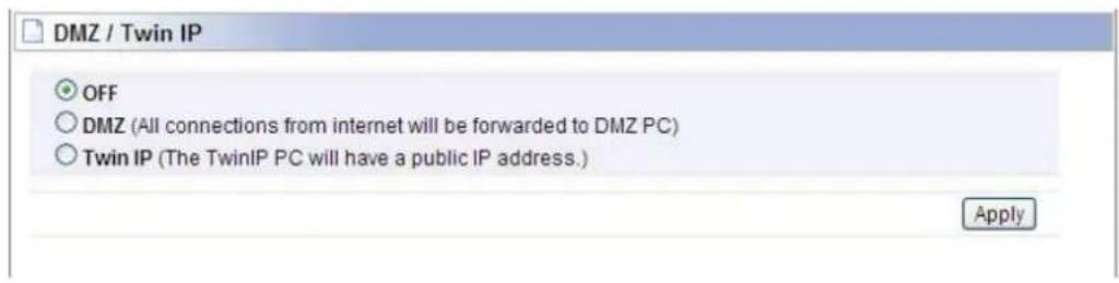
While you select DMZ option, you should enter the LAN IP address and click Apply to save configuration.
While you choose the Twin IP option, you should enter the MAC address and IP address.
6.4.3 Port Trigger
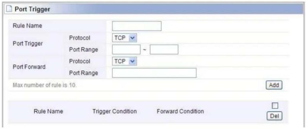
Port Trigger is used to realize that when there comes the Outbound streaming from a specified network port (triggered port), automatically opens the gateway WAN-side interfaces specified port (forwarded port), and the streams will forward to the triggered ports. You can achieve some special purposes by this setting.
6.4.4 Misc Setup
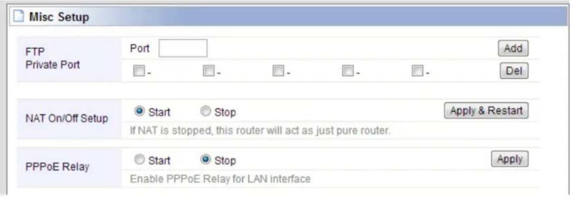
Misc setup provides FTP Private Port, NAT on/off setup and PPPoE relay.
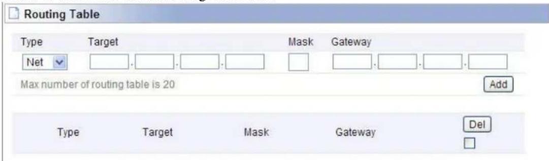
6.4.5 Routing Table
You can add or delete the static routing rules here.
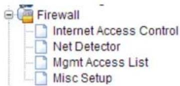
6.5 Firewall
Click the plus sign beside Firewall menu to show up all the parameters contained, see below:
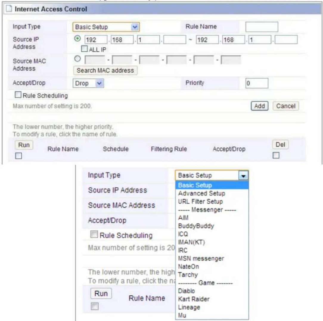
6.5.1 Internet Access Control
Internet Access Control provides multiple security protection. It can achieve MAC/Port/IP filtering, Internet access time control and other functions that enable user to control Internet access.
You can select different Internet type accordingly.
6.5.2 Net Detector
Net Detector provides some basic virus protection function that allows user to have a safer network communication.
![Net Detector Net Detector Setup Operation Start Stop Detection Port Well-known Worm Virus Ports All Ports Detection Level Mid 0 connections/sec Burst Drop No Only drop worm virus port E-mail Policy Please, set the email address of administrator & SMTP mail server. Apply Net Detector Log Send E-Mail immediately Clear All Events Detection Time IP Protocol Frequency Comment [Red:User Warning OFF]](/content/2026/05/788083/images/8d958f9fddeccb98f0a3a0f83d8178c978a93d7287c870746ec31629a1b6eef3.jpg)
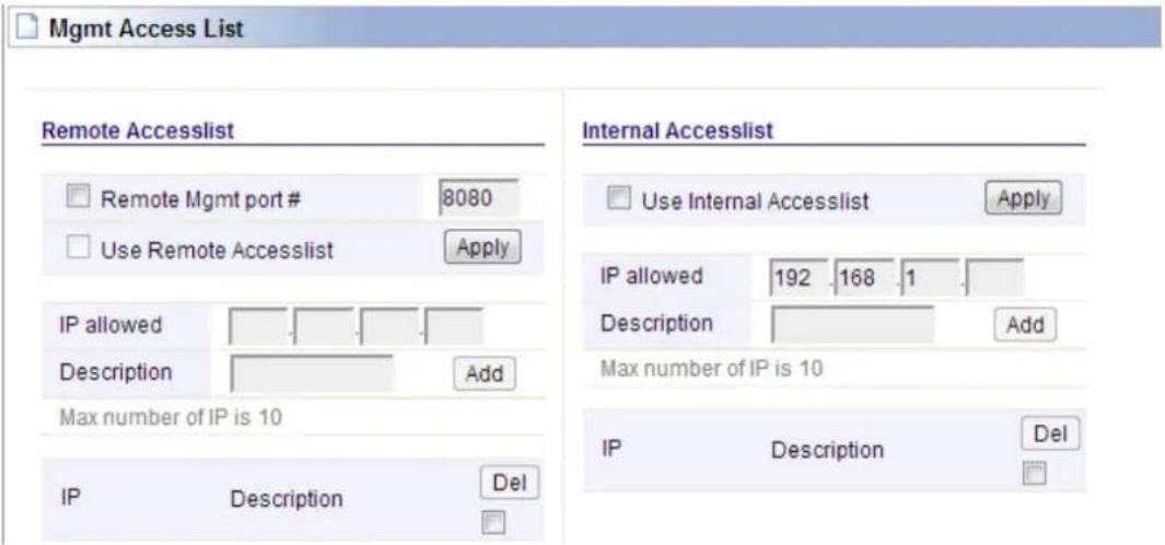
6.5.3 Mgmt Access List
In this section, you can configure remote and internal access list.
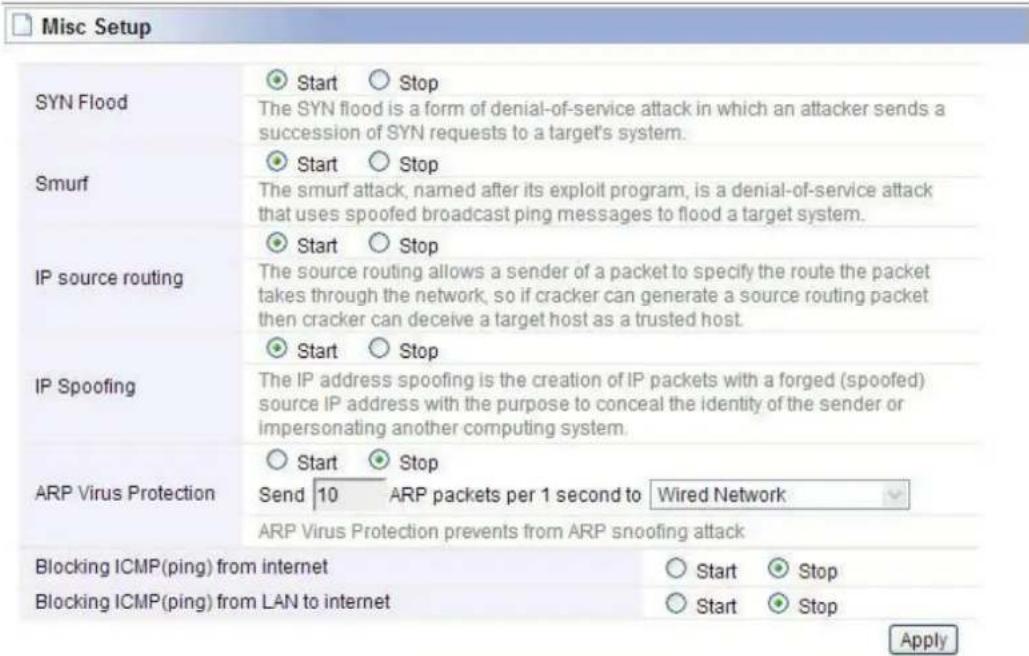
6.5.4 Misc Setup
Misc Setup: Generally maintain the default.
6.6 Utility
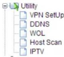
Click the plus sign beside Utility menu to open up all the parameters contained, please see below:
6.6.1 VPN Setup
The wireless router provides PPTP protocol VPN connection, and it supports 5 VPN users at most. Please enter the account information to connect the VPN server.
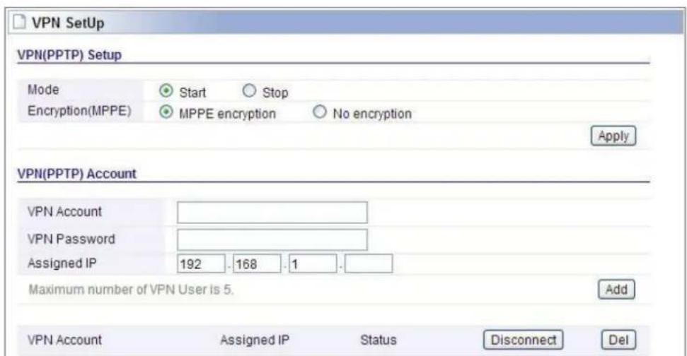
VPN (PPTP) Setup
Mode: Click Start to enable VPN server and otherwise disable.
Encryption (MPPE): MPPE encryption
Click Apply (this is very important, if you don't click Apply, the settings below will not work).
VPN (PPTP) Account
VPN Account & Password: Set the VPN account and password for verifying.
Assigned IP: This should be in the same network with your LAN IP.
Click Add. You can create at most 5 VPN accounts by this router. After setup, you need to provide the VPN Account, Password and your WAN IP address to anyone that needs them. The VPN Client should follow right steps to make a successful VPN connection.
6.6.2 DDNS
DDNS (Dynamic Domain Name Server) is to achieve a fixed domain name to dynamic IP resolution. For dynamic IP address users, if there is any Internet access to their IP address, they need to show a fixed domain name to them. So their IP address will be sent to the DDNS service provider from the dynamic analysis server (3322, dyndns.org) and to update the DNS database. Then DDNS will bind the dynamic IP address to a fixed domain name. When other users on the Internet want to access this domain name, the dynamic DNS server will return the correct IP address. In this way, most users do not need to use fixed IP and can also name the fixed network system.
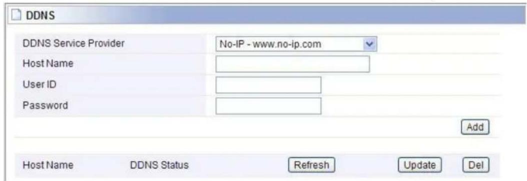
In order to set up DDNS, please follow the below steps:
- Choose your service provider.
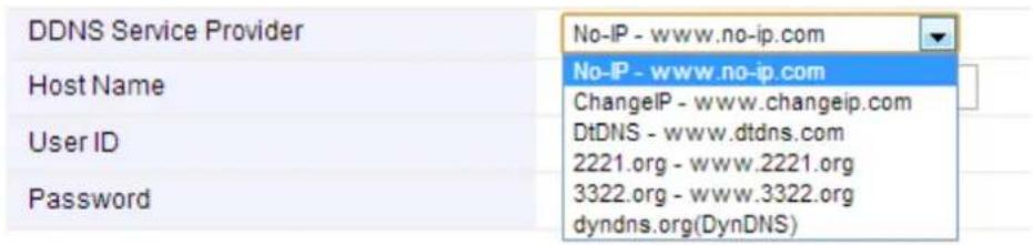
- Type in User Name for your DDNS account.
- Type in Password for your DDNS account.
- Host Name-the domain names are displayed here. Click Add to apply the modification.
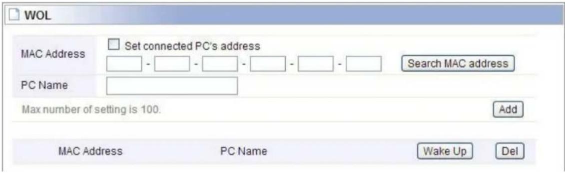
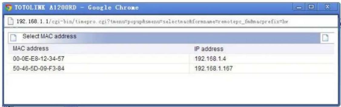
6.6.3 WOL
Users can use this Wake On Line function to start the PC remotely.
6.6.4 Host Scan
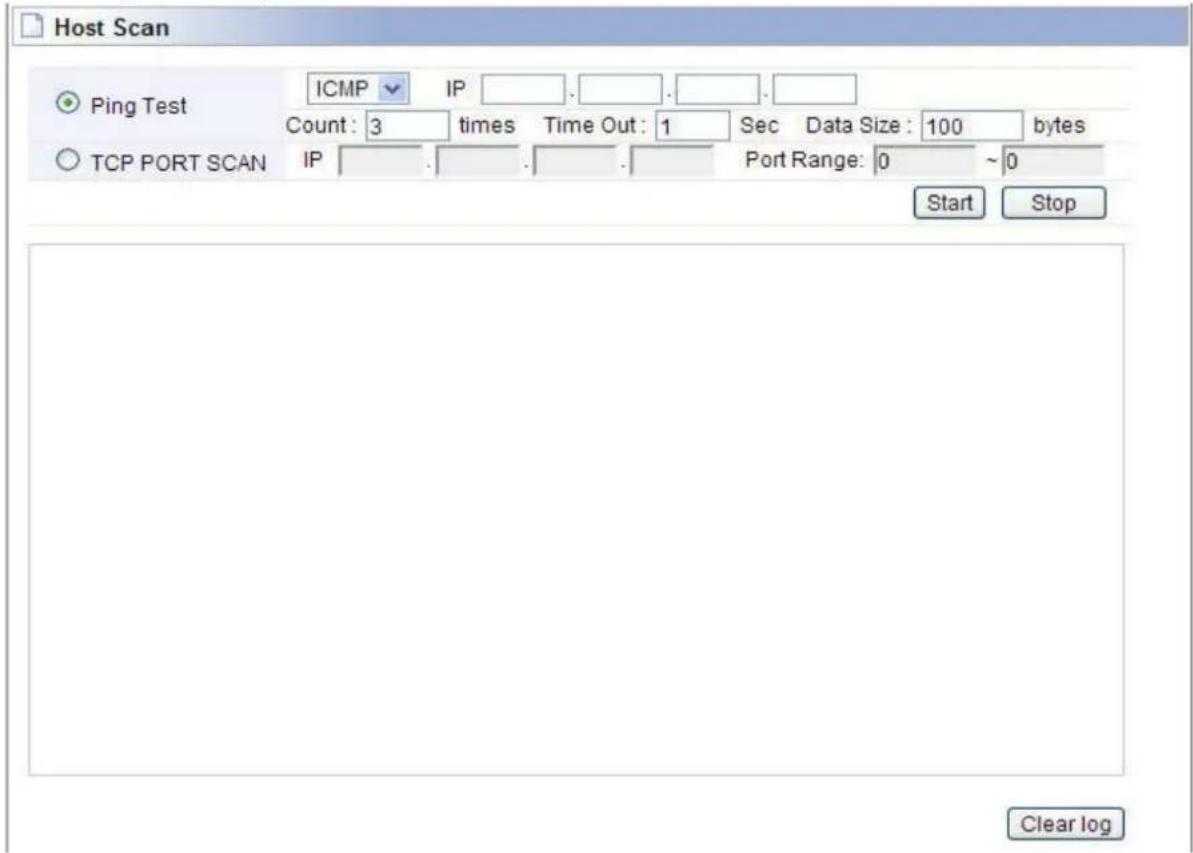
It allows user to view the working status of the PC, including status of ICMP, ARP package sending and receiving and TCP port communication information.
6.6.5 IPTV
The interface allows you to enable IPTV function for LAN 1 port. The setting is simple, just choose Use IPTV and click Apply & Restart button.

6.7 Traffic
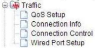
Click the plus sign beside the Traffic menu to show up all the parameters contained, see below:
6.7.1 QoS Setup
This page is used to control the wireless speed of connected PC.

Operation: You can choose to Start or Stop this function on your Router.
Internet Type: Any Internet type you want to control bandwidth.
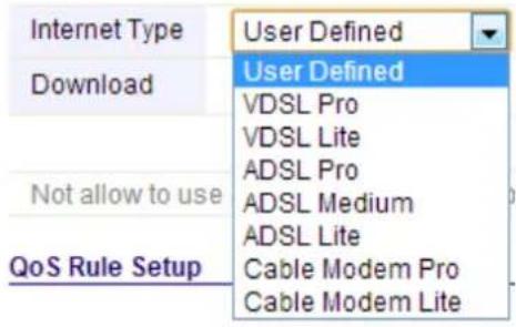
Download/Upload: Set the bandwidth range of the Router.
QoS Rule Setup
Mode: You could select Max. Limit (maximum limited bandwidth) or Min. Guarantee (minimum guaranteed bandwidth).
IP: You should type in the IP addresses range of PC in LAN.
Protocol: Select TCP, UDP or TCP/UDP Protocol for bandwidth control.
External Port: You need to enter the range of external ports that you want to control bandwidth.
6.7.2 Connection Info
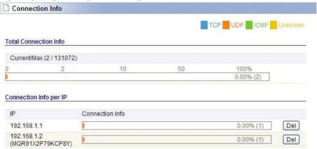
This page indicates the present connection information of the Wireless Router using graphics and data including data package sending and receiving status of each PC in connection.
bar
| Category | IP | Connection Info | | :--- | :--- | :--- | | Total Connection Info | 192.168.1.1 | 0.00% (1) | | Current/Max (2 / 131072) | 192.168.1.2 (MQR91X2P79KCP8Y) | 0.00% (1) | | Connection Info per IP | | | | TCP | | | | UDP | | | | ICMP | | | | Unknown | | |6.7.3 Connection Control
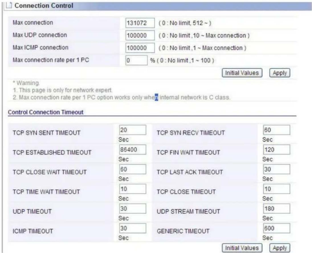
Connection Control shows the Max connection, Max UDP connection, Max ICMP connection and Max connection of each PC. These settings are only for advanced users, common users are not recommended to change them.
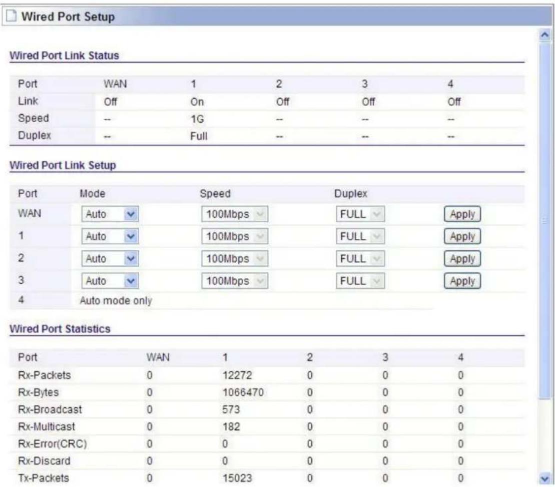
6.7.4 Wired Port Setup
This page shows the connection status of the PC connected with your router by cables.
6.8 System
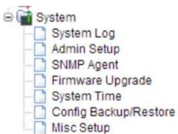
Click the plus sign beside the System menu to open up all the parameters contained, please see below:
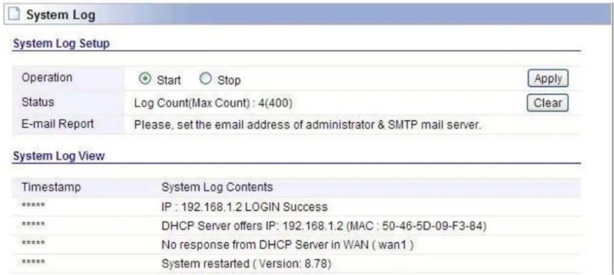
6.8.1 System Log
System Log shows the working status of the wireless router, user can check the running status information here:
6.8.2 Admin Setup
We have discussed Account Setup before; here we focus on Admin E-mail Setup.
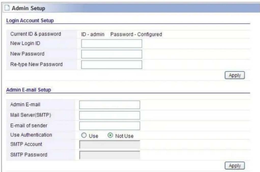
Admin E-Mail Setup: If you want to receive IP routing log by email, set up Email address and SMTP server to receive it.
6.8.3 SNMP Agent
Simple Network Management Protocol (SNMP) is an "Internet-standard protocol for managing devices on IP networks". It is used mostly in network management systems to monitor network-attached devices for conditions that warrant administrative attention.
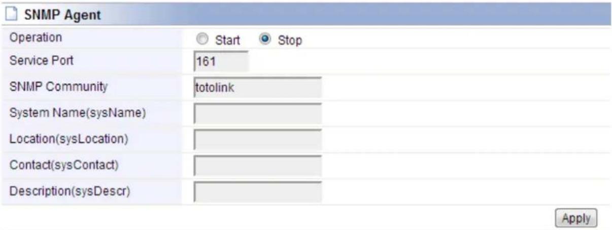
Operation: you can choose to Start/Stop to enable /disable this function.
Service Port: please enter the network port number of SNMP Agent. By default, it is 161.
SNMP Community: set the group name or just keep the default (totolink).
System Name/ Location/ Contact: set the administrator name, physical location and contact method.
6.8.4 Firmware Upgrade
New version of firmware will be released to improve the various efficiency or to fix some bugs. Following the steps show below so as to realize upgrading. This page allows you to upgrade the Access Point firmware to new version.
Please note: DO NOT power off the device during the upload because it may crash the system.
![Firmware Upgrade Firmware Version 8.88 Build Date Tue Dec 24 16:00:51 KST 2013 To upgrade manually - Click [Browse] and choose a downloaded firmware - Click [Upgrade] button. Choose File No file chosen Upgrade Note. • Internet will be unavailable for upgrading firmware. • Power down for updating firmware can be the cause of system halt.](/content/2026/05/788083/images/acad628d15de4d91168481f40b5d46899d583d53021ed7eb20abedde0c09de96.jpg)
6.8.5 System Time
You can set the time server and time zone for your wireless Router system time.

6.8.6 Config Backup/Restore
This webpage allows you to save current settings to a file and reload the settings from the file which was saved previously. Besides, you could reset the current configuration to factory default.
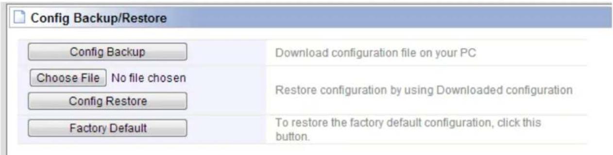
If you can't access the router's setup interface or simply forgot the router's password, you may reset the current configuration to factory default by pressing the RST Button for about 10 minutes.
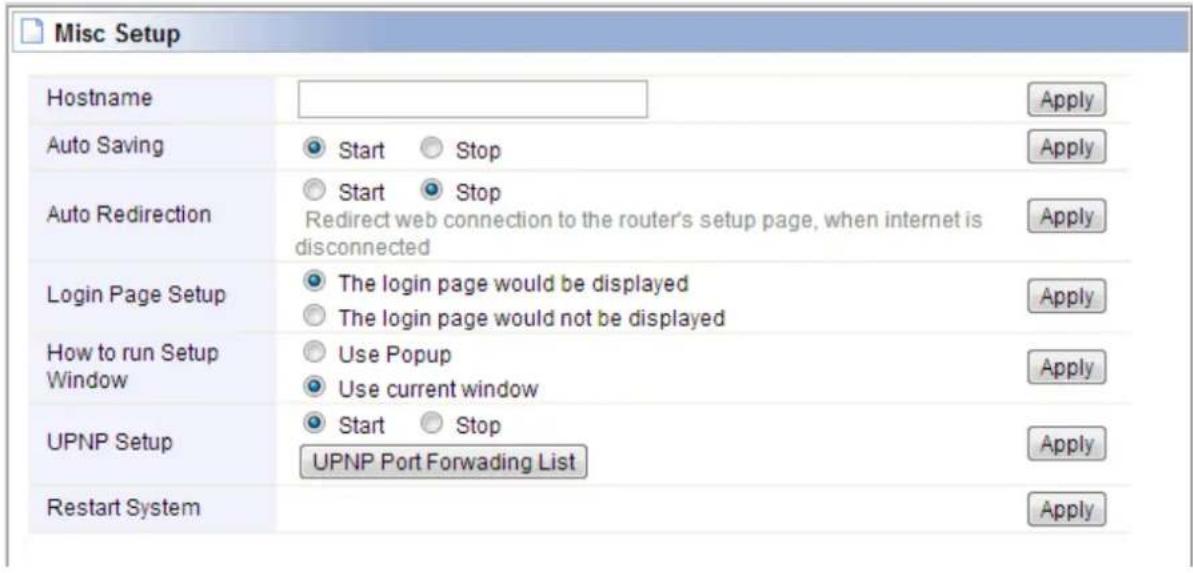
6.8.7 Misc Setup
Misc Setup provides Host name, Auto Saving, Auto Redirection, Login page setup, UPNP setup and Restart System functions.
6.9 USB Storage
With USB2.0 port, this router allows users to plug USB device and sharing information or server service with others in LAN & Internet.
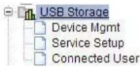
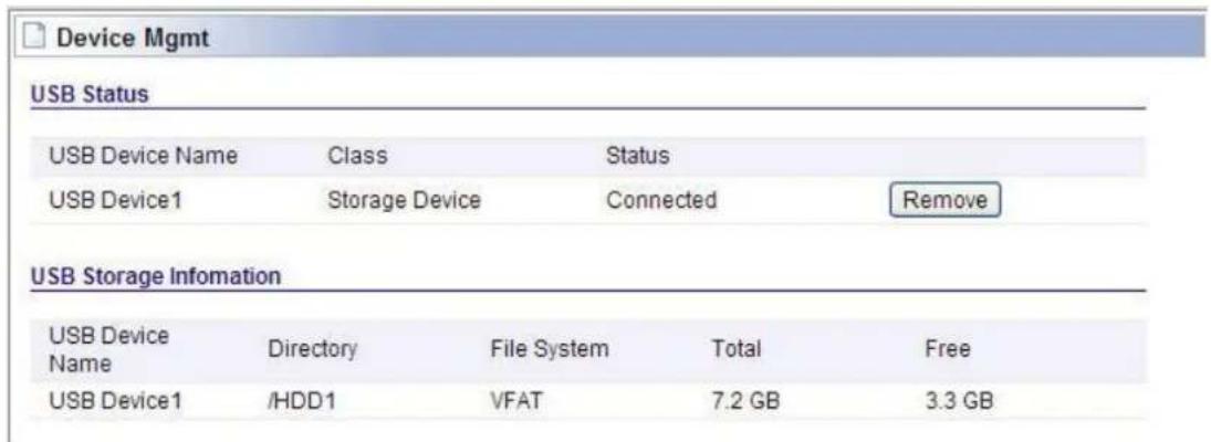
6.9.1 Device Mgmt
If you have plugged a USB device on the router, you can check the USB status and remove it on this page.
6.9.2 Service Setup
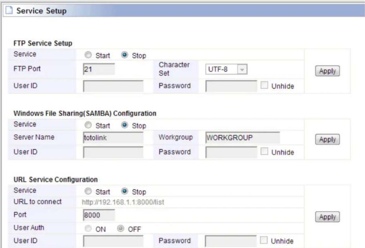
In this section, you can enable FTP Service, Samba service and URL service.
FTP service setup:
Service: click Start to enable this function and otherwise disable.
FTP Port: enter the FTP port number to use, the default is 21.
Character Set: setup the character encoding format, the default is UTF-8.
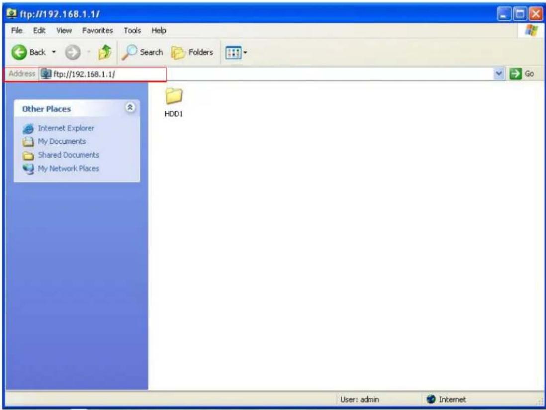
User ID & Password: provide the User ID & Password for verifying while enter the FTP server. After enable FTP service, you can enter ftp://192.168.1.1 in the address bar of My Computer or even of the web browser.
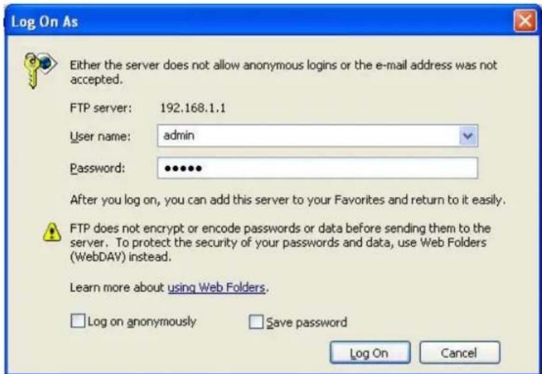
Then enter the user name and password you have setup to enter the FTP server. Then click Log On, so you can view the information of the USB device and even add files or delete files if you want.
Samba service setup:
Service: click Start to enable this function and otherwise disable.
Service Name: enter the name of the shared folder.
Workgroup: set the same workgroup as computer, by default it is WORKGROUP.
User ID & Password: provide the User ID & Password for verifying identity while enter the Samba server.
After configuration, you can see the shared folder in My Network Places in your PC.
URL service setup:
Port: enter the port number to use, the default is 8000.
User Auth: enable or disable login authentication.
User ID & Password: If you enabled login authentication, please provide the User ID & Password for verifying.
6.9.3 Connected User
In this page, you can check the IP Address and connection time about the device that connected to the server.
| Connected User | ||
| Service Name | IP Address | Time |
| FTP | 192.168.1.2 | 1970/01/01 00:10:00 |
- Table of Contents
- REVISION......4
- ABOUT THIS GUIDE ....5
- INTRODUCTION....5
- HARDWARE INSTALLATION ....8
- CONNECTING TO INTERNET....10
- Internet Setup.... 12
- Wireless Setup (2.4GHz) 15
- Wireless Setup (5GHz) 16
- ADVANCED SETUP ....17
- Network 18
- Wireless (2.4GHz) 21
- Wireless (5GHz) 29
- NAT/Routing 35
- Firewall 37
- Utility 40
- Traffic....43
- System 46
- USB Storage.... 50
- Copyright Statement
- REVISION
- Revision History
- ABOUT THIS GUIDE
- Overview of the User's Guide
- INTRODUCTION
- Overview
- Features
- Panel Layout
- Front Panel
- Rear Panel
- Antenna Placement
- HARDWARE INSTALLATION
- Hardware Installation
- Check the Installation
- Set up the Computer
- ♦ Obtain an IP address automatically
- Is the connection between your PC and the Router correct?
- Is the TCP/IP configuration for your PC correct?
- CONNECTING TO INTERNET
- Login Web Interface
- Changing Password
- Internet Setup
- DHCP User
- PPPoE User (ADSL)
- Static IP
- Wireless Setup (2.4GHz)
- Shared Key (WEP)
- WPA-PSK/WPA2-PSK (Recommended)
- Wireless Setup (5GHz)
- Firmware Upgrade
- ADVANCED SETUP
- Network
- Internet Status
- LAN Status
- Internet Setup
- LAN/DHCP Server
- DHCP Server Setup
- DHCP Static Lease Setup
- Static Lease (IP/MAC Address):
- Wireless (2.4GHz)
- Wireless Status
- Wireless Setup
- Multiple BSS
- Wireless Scheduler
- Wireless Multibridge
- MAC Authentication
- 2.4GHz MAC Authentication
- WDS Setup
- WPS Setup
- Advanced Setup
- Wireless (5GHz)
- Wireless Status
- Wireless Setup
- Multiple BSS
- Wireless Scheduler
- Wireless Multibridge
- MAC Authentication
- WDS Setup
- WPS Setup
- Advanced Setup
- NAT/Routing
- Port Forwarding
- DMZ / Twin IP
- Port Trigger
- Misc Setup
- Routing Table
- Firewall
- Internet Access Control
- Net Detector
- Mgmt Access List
- Misc Setup
- Utility
- VPN Setup
- VPN (PPTP) Account
- DDNS
- WOL
- Host Scan
- IPTV
- Traffic
- QoS Setup
- QoS Rule Setup
- Connection Info
- Connection Control
- Wired Port Setup
- System
- System Log
- Admin Setup
- SNMP Agent
- Firmware Upgrade
- System Time
- Config Backup/Restore
- Misc Setup
- USB Storage
- Device Mgmt
- Service Setup
- FTP service setup:
- Samba service setup:
- URL service setup:
- Connected User
Brand : Totolink
Model : A2004NS
Category : Router