UND A 12H - Air-conditioner UnicalAir - Free user manual and instructions
Find the device manual for free UND A 12H UnicalAir in PDF.


User questions about UND A 12H UnicalAir
0 question about this device. Answer the ones you know or ask your own.
Ask a new question about this device
Download the instructions for your Air-conditioner in PDF format for free! Find your manual UND A 12H - UnicalAir and take your electronic device back in hand. On this page are published all the documents necessary for the use of your device. UND A 12H by UnicalAir.
USER MANUAL UND A 12H UnicalAir
natural_image
Front view of a white Unical air conditioner unit with control panel and indicator lights (no visible text or symbols on the device itself)wall type air conditioners
• FOR THE AIR CONDITIONER TO OPERATE SATISFACTORILY, INSTALL IT AS OUTLINED IN THIS MANUAL
- BE CAREFUL NOT TO SCRATCH THE AIR CONDITIONER UNITS WHEN HANDLING THEM.
- CONNECT THE INDOOR UNIT AND THE OUTDOOR UNIT WITH PROPER CORDS AND AIR CONDITIONER PIPING
- MOVING A SPLIT AIR CONDITIONER TO ANOTHER LOCATION REQUIRES SPECIAL TECHNIQUE. IF NECESSARY, CONSULT WITH THE SELLER.
INSTALLATION ACCESSORIES
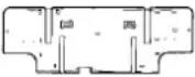 | Name and drawing Quantity Application | ||
| Wall hook bracket for the indoor unit 01 To mount the indoor unit | |||
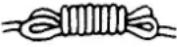 | Power cable 01 For interconnecting the indoor and outdoor units | ||
 | Pipette for condensed water drainage 01 For the outdoor unit drainage | ||
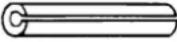 | Pipe insulation sleeve 01 To insulate the joints of the indoor unit | ||
 | Remote control 01 | ||
1
SELECTING THE INSTALLATION PLACE
INDOOR UNIT
• Install the indoor unit level on a strong wall that is not subject to vibrations.
- The inlet and outlet ports should not be obstructed: the air should be able to blow all over the room.
- Do not install the unit near a source of heat, steam, or flammable gas..
• Install the unit near an electric socket or private circuit.
- Do not install the unit where it will be exposed to direct sunlight.
• Install the unit where connection between indoor and outdoor unit is as easy as possible.
• Install the unit where it is easy to drain the condensed water.
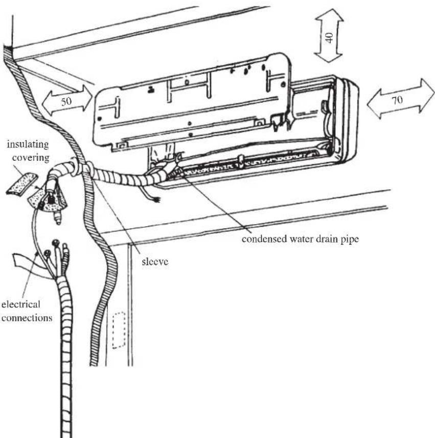
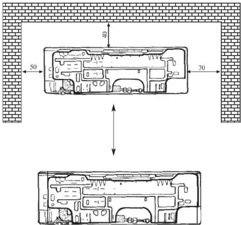
- Check the machine operation regularly and leave the necessary spaces as shown in the picture.
• Install the indoor unit where the filter can be easily accessible.
text_image
insulating covering electrical connections sleeve condensed water drain pipe 40 50 70minimum spaces to be left (mm)
text_image
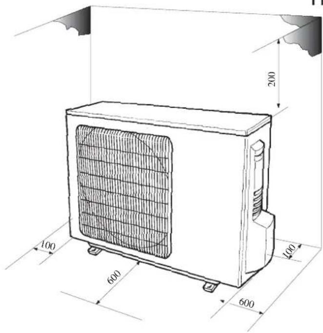
200 100 600 600 100OUTDOOR UNIT
- Do not install the outdoor unit near sources of heat, steam or flammable gases.
- Do not install the unit in too windy or dusty places.
- Do not install the unit where people often pass.
- Select a place where the air discharge and operating sound level will not disturb the neighbours.
- Avoid installing the unit where it will be exposed to direct sunlight (otherwise use a protection, if necessary, that should not interfere with the air flow).
- Leave the spaces as shown in the picture for the air to circulate freely.
• Install the outdoor unit in a safe and solid place. - If the outdoor unit is subject to vibration, fix rubber gaskets onto it.
OUTDOOR UNIT CONDENSED WATER DRAINAGE (only for heat pump models)
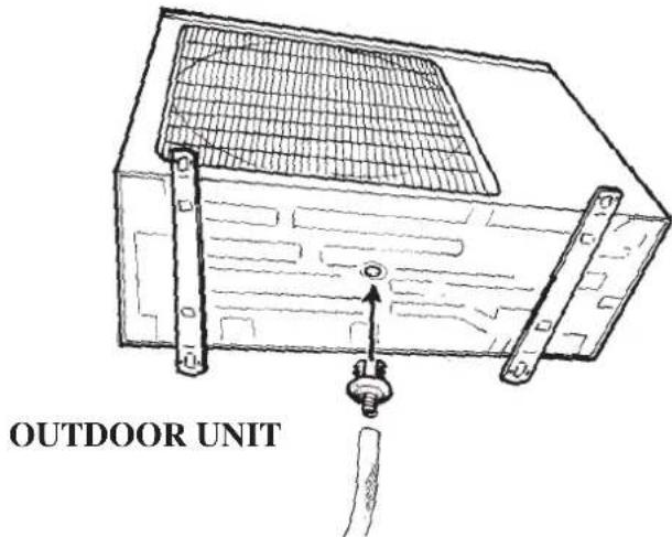
The condensed water and the ice formed in the outdoor unit during heating operation can be drained away through the drain pipette.
Installation: fasten the drain pipette in the 25 mm hole placed in the lower part of the unit as shown in the picture.
Connect the condensed water hose and the pipette. Pay attention that water is drained in a suitable place.
text_image
OUTDOOR UNIT2 INSTALLATION OF THE INDOOR UNIT
WALL HOOK BRACKET
text_image
40 50 70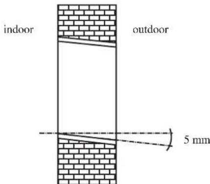
text_image
indoor outdoor 5 mmInstallation of the wall hook bracket
- By using a level, put the wall hook bracket in a perfect square position, both vertically and horizontally
- Fix the bracket first with 5 screws.
- Use several more tapping screws to secure the bracket onto the wall with even pressure on the screws.
- Cut a hole in the wall for the piping and electric connection.
N.B.
Drill a hole in the wall with the outdoor side 5-10 mm lower than the inner side, in order to have a good drain flow.
Note: The shape and dimensions of the wall hook bracket could be modified without prior notice.
NOTE : Maintain the drain pipe in the lower part of the wall hole, or leakage may occur.
Refrigerant piping connection
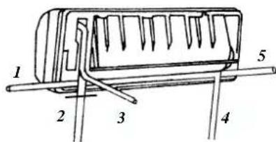
The piping can be run in the 5 directions indicated by numbers 1, 2, 3, 4, 5 in the figure. When the piping is run in direction 1, 2, 4 or 5, cut a notch along the groove on the side of the indoor unit with a cutter.
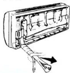
Run the piping in the direction of the wall hole and bind the copper pipes, the drain pipe and the power cables together with the tape with the drain pipe at the bottom, so that water can flow freely.
Indoor unit installation
- Run the bound pipe and cables through the wall hole and mount the indoor unit onto the upper part of the wall hook bracket securely
- Arrange the pipes and cables well.
- Push the lower part of the indoor unit tight against the wall hook bracket.
NOTE:
- Do not bend or crush the indoor unit piping. Avoid sharp bends with radius of curvature of less than 10 cm.
- Do not bend the same part of the pipe too often, after three times it could be throttled.
- Do not remove the flare nut from the indoor unit piping until immediately before connecting the connection pipe.
text_image
1 2 3 4 5The piping run towards the right
natural_image
Diagram of a car air conditioner unit with cooling fins and attached tubing (no text or labels)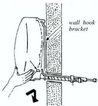
text_image
wall hook bracket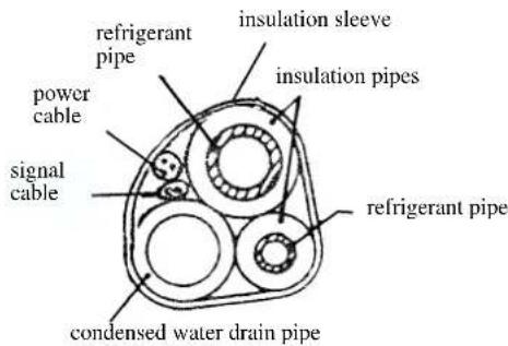
text_image
refrigerant pipe insulation sleeve power cable insulation pipes signal cable refrigerant pipe condensed water drain pipe3 INDOOR UNIT CONDENSED WATER DRAINAGE
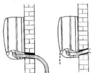
The indoor unit condensed water drainage is fundamental for the success of the installation.
- Install the drain hose at the bottom of the wall hole.
- The insulator of the copper pipes should be at least 6 mm thick.
natural_image
Diagram showing two pipe connection scenarios with a pipe and water droplets (no text or symbols)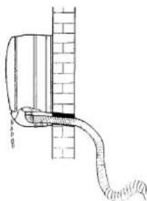
natural_image
Diagram of a pipe or tube inserted into a brick wall, showing fluid flow direction (no text or labels)YES NO NO
Check that:
- The top and bottom hooks of the indoor unit are hooked firmly on the wall hook bracket.
- The unit is positioned horizontally. If the unit is not installed properly, water will drip onto the floor.
- The drain hose has the correct gradient (at least 3 cm for every meter in length).
- The drain hose remains at the bottom of the wall hole.
4 OUTDOOR UNIT INSTALLATION
The outdoor unit should be installed on a solid wall and fastened securely
The following procedure must be observed before connecting the pipes and electric cables:
- decide which is the best position on the wall and leave enough space to be able to carry out maintenance easily.
- fasten the support to the wall using screw anchors which are particularly suited to the type of wall;
- use a larger quantity of screw anchors than normally required for the weight they have to bear: during operation the machine vibrates and has to remain fastened in the same position for years without the screws becoming loose.
ATTENTION: ONLY ACR copper pipes for air conditioners are allowed
Connecting the pipes
- Do not remove the cap from the pipe until connecting it, to avoid dampness or dirt from entering.
- If the pipe is bent or pulled too often, it will become stiff. Do not bend the pipe more than three times at one place.
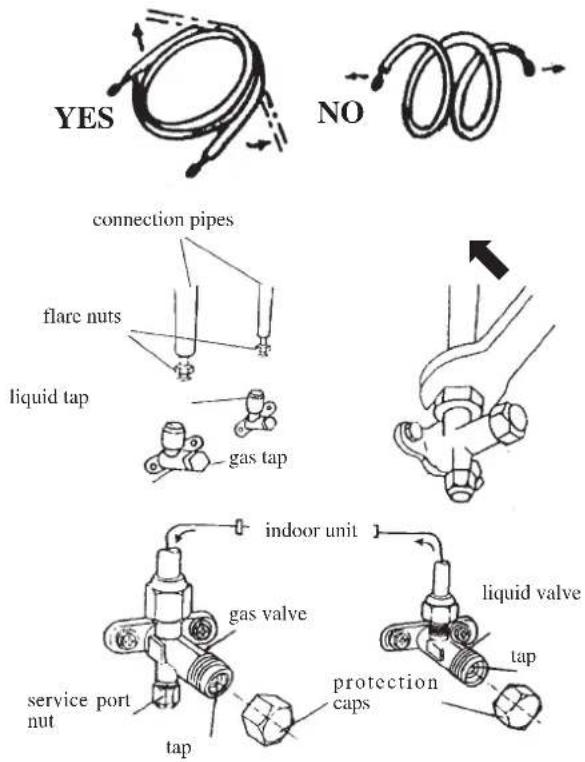
- When extending the rolled pipe, straighten the pipe by unwinding it gently as shown in the figure below
CONNECTIONS TO THE INDOOR UNIT
- Shape the connection pipe following the diagram.
- Remove the indoor unit pipe cap (check that there is no debris inside).
- Insert the flare nut and create a flange at the extreme end of the connection pipe.
- Connect the pipes by using two wrenches.
CONNECTIONS TO THE OUTDOOR UNIT
Screw the flare nuts to the outdoor unit coupling with the same tightening procedures described for the indoor unit.
text_image
YES NO connection pipes flare nuts liquid tap gas tap indoor unit gas valve service port nut tap protection caps liquid valve tapTo avoid leakage, pay particular attention to the following points:
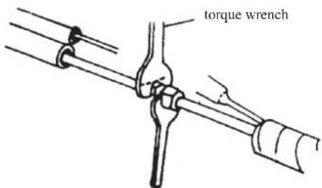
- Tighten the flare nuts using two wrenches. Pay attention not to damage the pipes.
- If the tightening torque is not sufficient, there will probably be some leakage. With excessive tightening torque there will also be some leakage, as the flange could be damaged.
- The surest system consists in tightening the connection by using a fix wrench and a torque wrench: in this case use the following table.
FLANGE CONNECTION TIGHTENING TORQUE
| Pipe Tightening torque Corresponding stress | [N x m] (using a 20 cm wrench) | |
| 6,35 mm ( ^1/_4 ") | 15 - 20 wrist strength | |
| 9,52 mm ( ^3/_8 ") | 31 - 35 arm strength | |
| 12,70 mm ( ^1/_2 ") | 50 - 55 | arm strength |
| 15,88 mm ( ^3/_8 ") | 65 - 70 | arm strength |
TIGHTENING TORQUE FOR PROTECTION CAPS
| Tightening torque[N x m] | |
| Service port nut 7 - 9 | |
| Protection caps 25 - 30 |
To empty the refrigerant pipe from air and humidity, the use of the vacuum pump is recommended.
text_image
torque wrench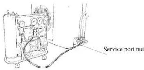
text_image
Service port nutIMPORTANT : REFRIGERANT LEAKAGE INSPECTION
After connecting the piping, check the joints for refrigerant leakage with leak detector carefully.
INFORMATION FOR THE INSTALLER
| MODEL | 7000-9000 BTU/h | 12000 BTU/h |
| Liquid pipe diameter | 1/4" | 1/4" |
| Gas pipe diameter | 3/8" | 1/2" |
| Maximum lenght of pipe with standard charge | 5 m | 5 m |
| Maximum distance between indoor and outdoor unit | 15 m | 15 m |
| Additional gas charge | 25 g/m | 25 g/m |
| Maximum difference in level between indoor and outdoor unit (1) | 5 m | 5 m |
| Type of refrigerant | * | * |
* refer to the data sticker sticked the outdoor unit
(1) ATTENTION: In case the outdoor unit has been installed higher than the indoor unit, it is necessary to provide "S" oil traps (or liquid separator) to both refrigerant pipes, over 2 m of difference in level.
6 ELECTRICAL CONNECTIONS
INDOOR UNIT 7000 - 9000 - 12000 BTU/h
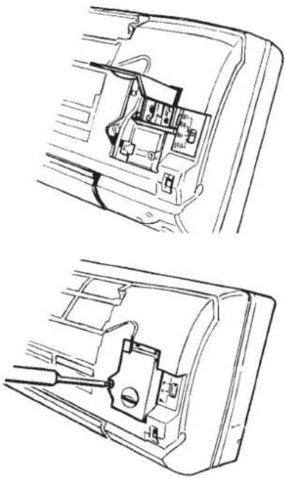
- Lift the front panel.
- Take off the cover as indicated in the figure.
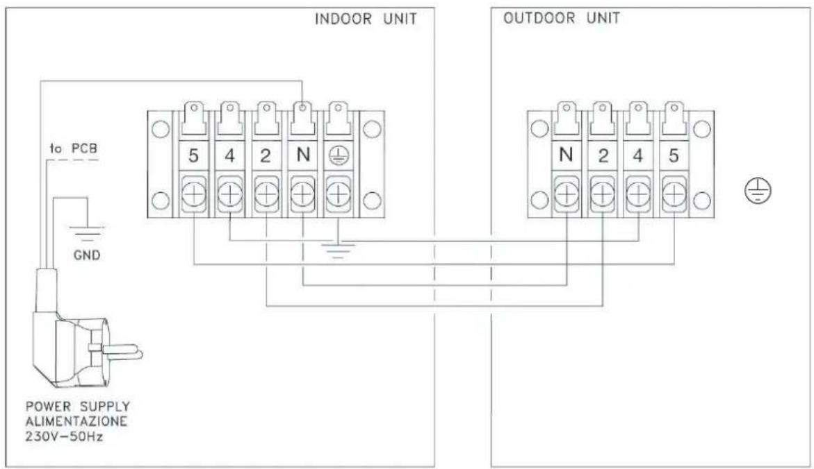
- Connect the cable wires to the screw terminals by following the numbering.
Use wire size suitable to the electric power input (see name plate on the unit) and according to all current national safety code requirements.
natural_image
Technical line drawing of a device interior showing internal components and wiring (no text or symbols)OUTDOOR UNIT 7000 - 9000 - 12000 BTU/h
- Take the cover away.
- Connect the cable wires to the terminal board using the same numbering as in the indoor unit.
- Fasten the cables with a cable-clamp.
- Replace the covers again.
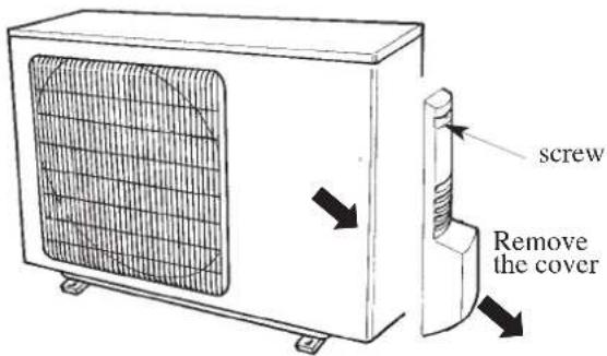
text_image
screw Remove the coverN.B.: The unit must be connected to the power supply system through an onnipolar switch (3 mm distance). In case the power supply cable is damaged, it must be replaced by the manufacturer or qualified staff.
INFORMATION FOR THE INSTALLER
| MODELLO 18000 BTU/h 24000 BTU/hLiquid pipe diameter 1/4" 3/8" | ||
| Gas pipe diameter 1/2" 5/8" | ||
| Max. pipe length with standard charge 4 m 4 m | ||
| Max. distance between indoor and outdoor unit15 m15 m | ||
| Gas supplementary charge 50 g/m 50 g/m | ||
| Max. difference in level between indoor and outdoor unit | 5 m 5 m | |
| Refrigerant type * * |
* Always refer to the technical data label on the outdoor unit
6 ELECTRICAL CONNECTIONS
INDOOR UNIT 18000 - 24000 BTU/h
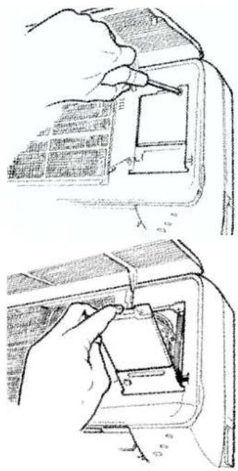
text_image
Technical diagram showing two steps of installing or adjusting a device panel, with Chinese labels indicating components and assembly.-
Lift the front panel.
-
Take off the cover as indicated in the figure.
-
Connect the power cable wires to the screw terminals by following the numbering and insert the signal cable connector (for heat pump version only).
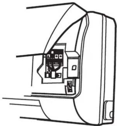
natural_image
Technical line drawing of a mechanical component with internal components (no text or symbols)OUTDOOR UNIT 18000 - 24000 BTU/h
- Take the cover away.
- Connect the signal cable connector (only for heat pump version).
- Connect the power cable wires to the terminal board using the same numbering as in the indoor unit.
- Fasten the cables with a cable-clamp.
- Replace the covers again.
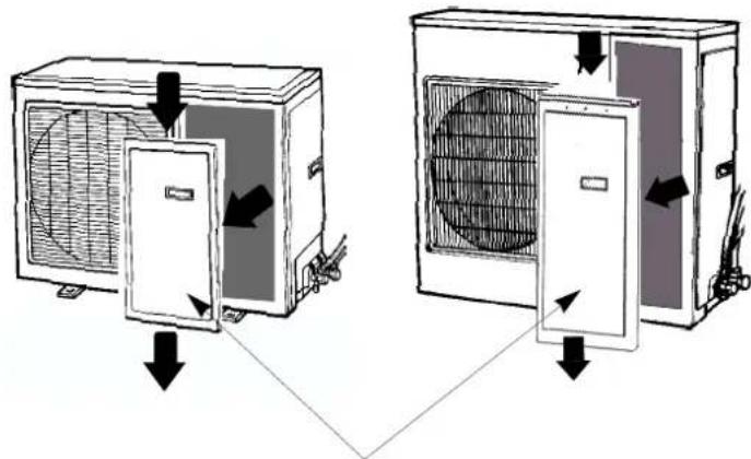
natural_image
Diagram showing airflow or ventilation between two air conditioning units, with arrows indicating direction of movement (no text or labels present)unscrew and take off the front panel
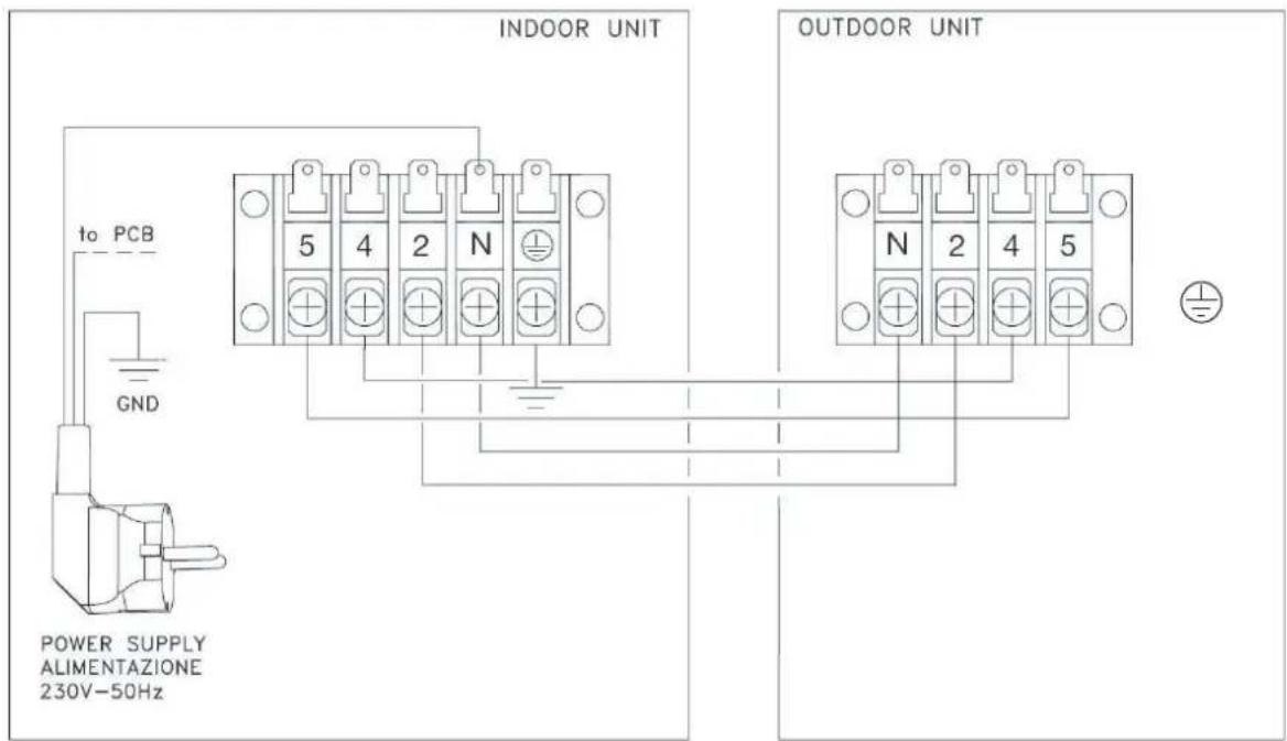
CONNECTION WIRING DIAGRAM FOR MODELS
R410a 7000 - 9000 - 12000 BTU/h
text_image
INDOOR UNIT to PCB GND POWER SUPPLY ALIMENTAZIONE 230V-50Hz OUTDOOR UNIT N 2 4 5CONNECTION WIRING DIAGRAM FOR MODELSDUAL SPLIT
text_image
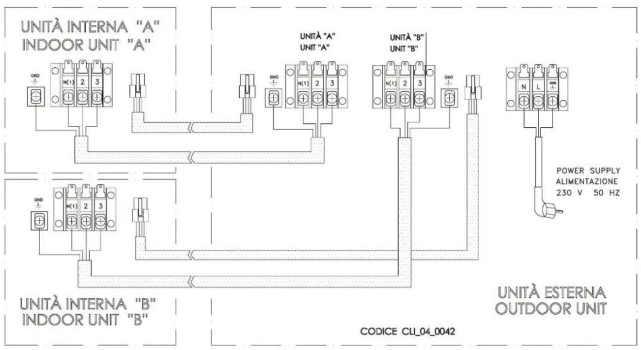
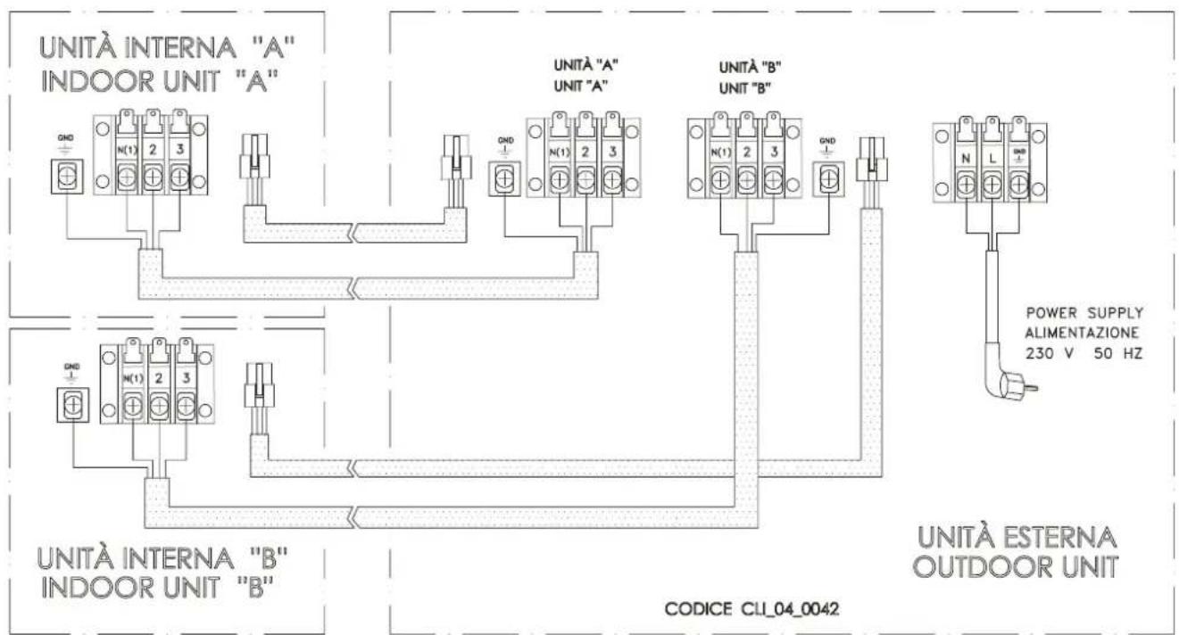
UNITÀ INTERNA "A" INDOOR UNIT "A" UNITÀ "A" UNIT "A" UNITÀ "B" UNIT "B" UNITÀ INTERNA "B" INDOOR UNIT "B" UNITÀ ESTERNA OUTDOOR UNIT CODICE CLI_04_0042 POWER SUPPLY ALIMENTAZIONE 230 V 50 HzConnect the power cable wires to the screw terminals by following the numbering; ensure that a properly sized and connected ground wire is in a place.
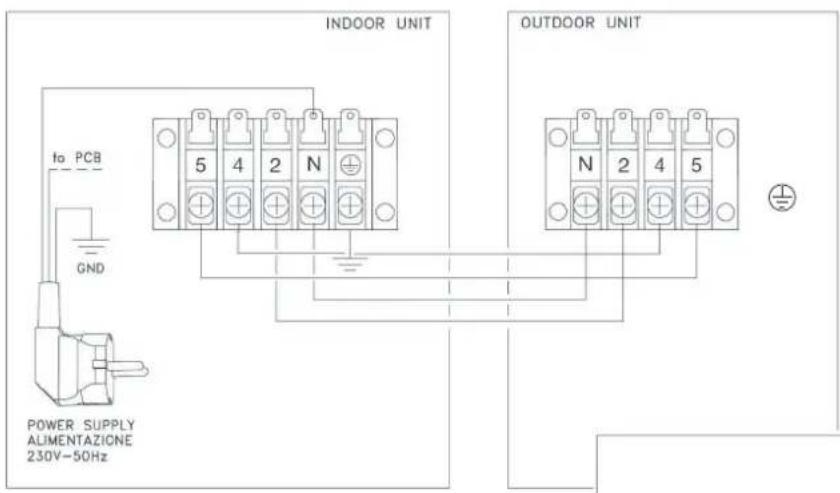
CONNECTION WIRING DIAGRAM FOR MODELS
18000 BTU/h (heat pump)
text_image
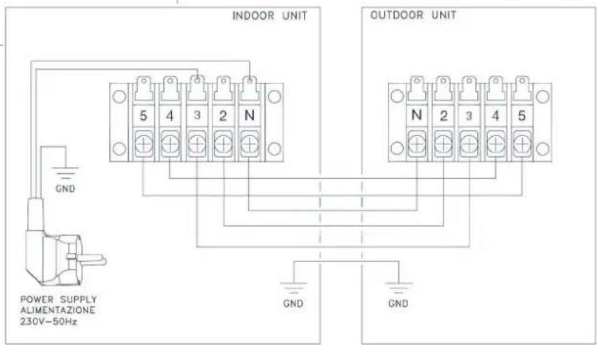
INDOOR UNIT to PCB GND POWER SUPPLY ALIMENTAZIONE 230V-50Hz OUTDOOR UNIT N 2 4 524000 BTU/h (heat pump)
text_image
INDOOR UNIT GND POWER SUPPLY ALIMENTAZIONE 230V-50Hz OUTDOOR UNIT N 2 3 4 5 GND GNDConnect the power cable wires to the screw terminals by following the numbering.
7
FINAL STAGES
- Wind insulating covering around the joints of the indoor unit and fix it with insulating tape.
- Fix the exceeding part of the signal cable to the piping or to the outdoor unit.
- Fix the piping to the wall (after having coated it with insulating tape) using clamps or insert them into plastic slots.
- Seal the hole in the wall through which he piping is passed so that no air or water can filter.
INDOOR UNIT TEST
☐ Do the ON/OFF and FAN keys operate normally?
□ Does the MODE key operate normally?
☐ Do the set point and TIMER keys function properly?
□ Does each lamp light normally?
☐ Do the louvers for air flow direction operate normally?
☐ Is the condensed water drained regular?
OUTDOOR UNIT TEST
☐ Is there any abnormal noise or vibration during operation?
□ Could the noise, the air flow or the condensed water drainage disturb the neighbours?
□ Is there any coolant leakage?

text_image
insulating covering piping insulating tape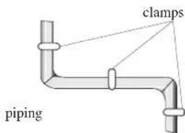
text_image
clamps piping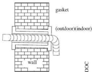
text_image
gasket (outdoor)(indoor) wall DOCNOTE: The electronic controller allows the compressor to start only three minutes after voltage has reached the system.
After installation, explain the correct operation to the Customer using the Instruction Handbook. Let the Customer keep this installation handbook because it may be referred to when the air conditioner is serviced or moved.
natural_image
Technical line drawing of a mechanical component with no visible text or symbols
text_image
dima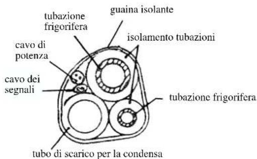
natural_image
Technical line drawing of a mechanical component with no visible text or symbols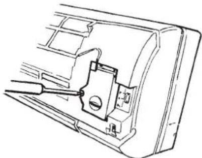
natural_image
Technical line drawing of a mechanical component with wires and a central connector (no text or symbols)UNITÀ ESTERNA 7000 - 9000 - 12000 BTU/h
text_image
Hand-drawn diagram showing a hand using a tool to adjust or install a component, with numbered parts and Chinese labels.natural_image
Hand inserting a component into a device (no text or symbols visible)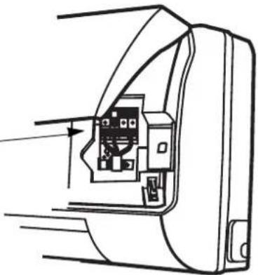
natural_image
Technical line drawing of a mechanical component with internal components and an arrow indicating direction (no text or symbols)UNITA' ESTERNA 18000 - 24000 BTU/h
text_image
coperchioSCHEMA ELETTRICO DI COLLEGAMENTO PER MODELLI R410a 7000 - 9000 - 12000 BTU/h
text_image
INDOOR UNIT to PCB GND POWER SUPPLY ALIMENTAZIONE 230V-50Hz OUTDOOR UNIT N 2 4 5SCHEMA ELETTRICO DI COLLEGAMENTO PER MODELLI
DUAL SPLIT R410A