Ingo-man Weco Touchless - Soap dispenser Ophardt - Free user manual and instructions
Find the device manual for free Ingo-man Weco Touchless Ophardt in PDF.


User questions about Ingo-man Weco Touchless Ophardt
0 question about this device. Answer the ones you know or ask your own.
Ask a new question about this device
Download the instructions for your Soap dispenser in PDF format for free! Find your manual Ingo-man Weco Touchless - Ophardt and take your electronic device back in hand. On this page are published all the documents necessary for the use of your device. Ingo-man Weco Touchless by Ophardt.
USER MANUAL Ingo-man Weco Touchless Ophardt
natural_image
Simple white lowercase 'i' symbol on gray background, no additional text or symbolsPlease read through carefully these operating instructions prior to initial operation and keep it.
In case of a resale of the apparatus, please pass on these operating instructions to the buyer.
Rückseite Back side
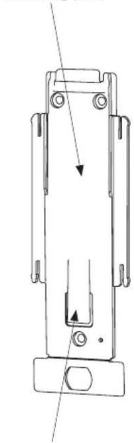
Montageplatte
Mounting plate
natural_image
Technical line drawing of a mechanical component with no visible text or symbolsMontagezunge Mounting tongue
text_image
Diagram showing a device emitting sound waves near a wall, with a no-smoking sign and a mobile phone icon nearby.Vor Spendermontage beachten
natural_image
Technical line drawing of a mechanical device with mounting holes and internal components (no text or symbols)6.2 Montage
text_image
Technical diagram showing a device with labeled parts and warning indicators, alongside a hand holding a document.natural_image
Illustration of two hands performing a manual task: one holding a tool, the other holding a device (no text or symbols present)natural_image
Illustration of a hand holding a small mechanical component with an arrow indicating rotation (no text or symbols present)natural_image
Illustration of a hand holding a small object with an arrow indicating rotational motion (no text or symbols)6.3 Demontage
natural_image
Illustration of a hand holding a device with an arrow indicating motion (no text or symbols)natural_image
Line drawing of a hand holding a tool with an arrow indicating direction (no text or symbols)natural_image
Illustration of hands using a tool to adjust or install a device, with an arrow indicating the process (no text or symbols present)natural_image
Technical line drawing of a mechanical bracket or mounting component with an arrow indicating direction (no text or symbols present)natural_image
Pure mechanical component diagram without any text, numbers, or symbolsnatural_image
Line drawing of a hand holding a device with an arrow indicating rotation (no text or symbols)7.2 Gerät benutzen
natural_image
Line drawing of a mechanical device with handle and internal components (no text or symbols)natural_image
Line drawing of a hand holding a device with a handle and lock (no text or symbols)8. Grundbedienung
natural_image
Line drawing of hands installing or adjusting a device with a handle (no text or symbols)natural_image
Illustration of hands holding a device with a hand pointing at it, showing internal components and a directional arrow (no text or symbols)text_image
Diagram showing a device with warning symbol and an arrow pointing to it, indicating hazard or caution.9. Pumpenwechsel
text_image
Safety warning diagram showing incorrect and correct safety symbols with labeled componentstext_image
bee p bep pnatural_image
Technical line drawing of a mechanical component being adjusted, with an inset showing close-up detail (no text or symbols)natural_image
Technical line drawing of a mechanical assembly with no visible text or symbolsnatural_image
Mechanical assembly diagram showing a rotating device with directional arrows indicating motion (no text or symbols)natural_image
Illustration of a hand holding a device with an arrow indicating motion (no text or symbols)10. Behältertausch
natural_image
Illustration of a hand using a tool to adjust or install a mechanical component (no text or symbols visible)natural_image
Line drawing of a mechanical device with a handle and base, no text or symbols present12. LED-Anzeige
natural_image
Simple line drawing of a stand with a U-shaped frame and a hanging hook (no text or symbols)text_image
Diagram showing hand positioning a device with numbered parts, likely illustrating a mechanical or electrical component.natural_image
Technical line drawing of a mechanical device with an inset close-up showing a detail (no text or symbols)natural_image
Two illustrations of showerheads with no shower, one without a circular prohibition symbol and the other with a spray gun (no text or labels)
text_image
beep b = p to dp4 x = Batterie voll

3 x = 34 voll

2 x = 1/2 voll

1 x = 14 voll

- Indications for the use of the service instructions / 2. Safety information
1. Indications for the use of the service instructions
The following symbols are used in the instructions
Safety reference:
A non-observance may cause damage to persons ondefects at the device

Supplementary information concerning the operation of the appliance
2. Safety information

Attention!
OPHARDT does not assume any liability for damages in the case of:
• defects at the appliance caused by mechanical influences or overvoltage
- changings at the appliance without express approval of OPHARDT
- use for other purposes than that mentioned in the application
2. Safety information
2.1 General safety
⚠️• Repairs at the appliance may exclusively be carried out by OPHARDT employees or persons authorized by OPHARDT. Important dangers may occur by unexpert repairs. In case of a necessary repair please contact the OPHARDT service department.
⚠️ • Suspend the appliance on a dry and splash-proof place.
This appliance is not a toy. Keep and use it out of the reach of children.
The appliance is not suitable for the transportation of media.
The appliance is not suitable for the metering of other than the indicated media.
Exclusively operate the appliance with leakproof alcalic batteries of the same manufacturer and type and with the same charging condition. Only use batteries with the indicated size type D.
Do not operate the appliance with rechargeable batteries (accumulators).
Do no longer use the apparatus if batteries have leaked in the appliance.
⚠️ • Never use force.
⚠️• Take the batteries from the appliance prior to cleaning and attendance.
⚠️ • Dispose of the empty batteries at the collecting points.
⚠️ The appliance needs not be disassembled, no repairable parts.
⚠️ The face shield is not removable.
2.2 Safety during operation of the appliance
⚠️ • Protect your appliance against humidity.
Do not expose the appliance to thermal radiation and heat.
⚠️• Never submerge the appliance in the water.
- Only fill the appliance with the indicated substances in accordance with the intended use.
There are no dismountable parts with the exception of pump, receptacle, battery cover, mounting plate, batteries, sealing diaphragm (accessories)
The appliance is not autoclavable and cannot be cleaned in the dishwasher.
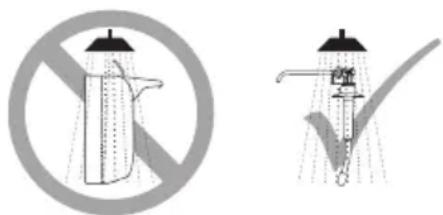
The apparatus shouldn't be cleaned with water jets or by means of a high-pressure cleaner.
⚠️ • Please make sure that the medium does not reach the ground.

3. Intended use
3. Intended use
The appliance is suitable for the touchless hands'disinfection. Furthermore the appliance can be used for the dispensing of liquid soaps for washing one's hands.
It is necessary to rub the medium into the hands.
The apparatus is exclusively designed for battery operation.
Always hang the dispenser upright on to the wall. The dispenser shouldn't be mounted freely.
The appliance can only be used in closed rooms.
Use the appliance for hands'disinfection and cleaning with the usual application cycles.
Ambient conditions:
- Never use the appliance in potentially explosive areas.
- Only use the appliance in a dustless environment.
- Pay attention to that the apparatus is only used at a relative air moisture of < 90% (not condensing).
- Only use this apparatus at room temperature.
Media to be used:
- The used medium has to be free-flowing at room temperature.
In case of doubt please test your medium for suitability. - The appliance is designed for operation with disinfectants or with liquid soap.
- The appliance is not suitable for operation with abrasive and aggressive media.
- Foodstuff as medium is not permissible.
3.1 Operation of the dispenser according to the regulations
In order to always guarantee an optimum functioning of the dispenser the following has to be observed:
- Use of the dispenser only with original parts.
- Only use disinfectants or thin liquid soap.
- When inserting the batteries please absolutely pay attention to the correct polarity! (Pay attention to the representation in the case).
- The dispenser may not be located close to radiation-emitting or statically charged objects while it is used.
- The dispenser only meters with closed face shield.
- In general (and especially during operation of the dispenser) a contact with the face shield has to be avoided.
- The emergency operating lever has to be actuated exclusively in case of a breakdown of automatic function!

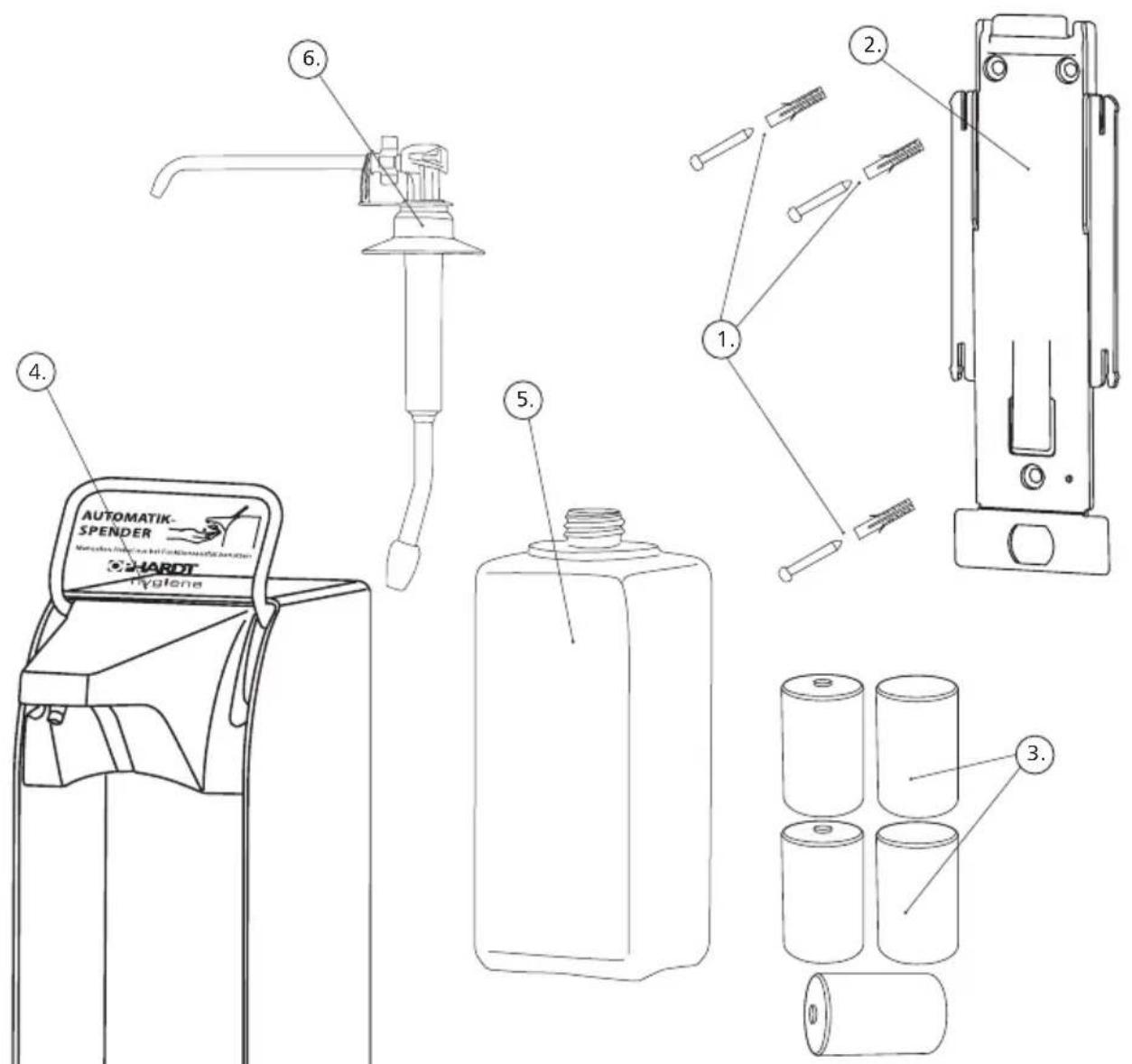
4. Component parts of the dispenser / scope of delivery
text_image
AUTOMATIK- SPENDER HAGET HYGONE 6. 4. 5. 2. 1. 3.No. Designation
- | fixing set with dowels and screws
- | mounting plate
- | batteries (5 mono-cells, type D)
- | dispenser ingo-man ^® plus Touchless
- | receptacle
- | pump for ingo-man ^® plus Touchless

5. Technical description
5. Technical description
The appliance meters free-flowing media by means of a removable suction pump from an exchangeable receptacle which is inserted into the dispenser. The dosage per pump stroke each can be modified by adjusting the pump.
The appliance recognizes by means of a touchless sensor technique and a hand approaching the outlet and, thus, automatically releases a pump stroke. Further pump strokes are carried out if the lower hand remains uninterruptably in the lower sensor area and a second hand is lead to the upper sensor area.

6. Mounting of the dispenser
6. Mounting of the dispenser
6.1 Preparation of the installation
Place the dispenser above the washstand or right next to it. If this is not possible, one has to take care by means of adequate equipment that no medium pours out on the floor.
• Prior to the use of new filling media tests are required!
- Please pay attention to that during installation no radiation-emittent object (i.e. X-ray apparatus, mobile telephone... etc.) is in the near proximity. Electromagnetic interference sources and/or radiating electric fields may impair the function.

text_image
Diagram showing a device emitting sound waves to a mobile phone, with no visible text or symbols.Prior to the mounting of the dispenser please observe the following
- Required place above the dispenser:
40 mm (for putting on and removing from the mounting plate). Please take the required place below the dispenser from the dimensioned sketch.
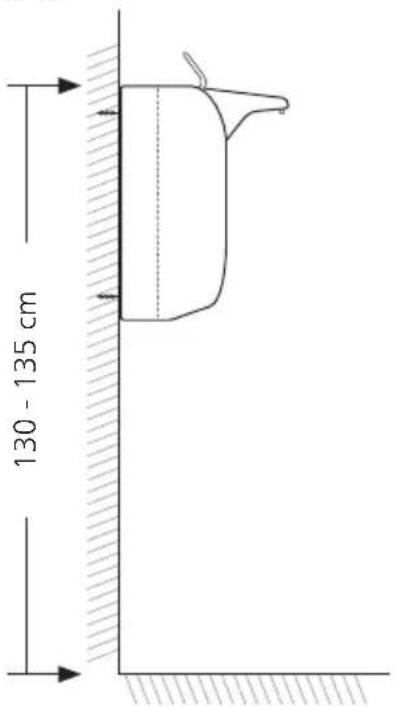
- Suitable mounting height:
130-135 cm, measured from the floor up to the upper edge of the dispenser.
text_image
130 - 135 cm
6. Mounting of the dispenser
natural_image
Illustration of a hand holding a small object with an arrow indicating rotation (no text or symbols)6.2 Mounting
For the mounting and going into operation of the ingo-man® Touchless please keep the following steps in sequence.
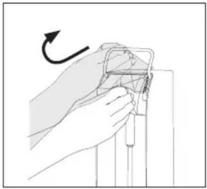
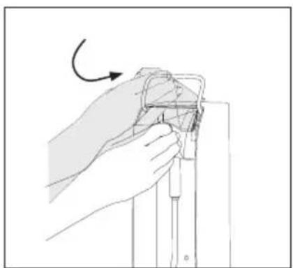
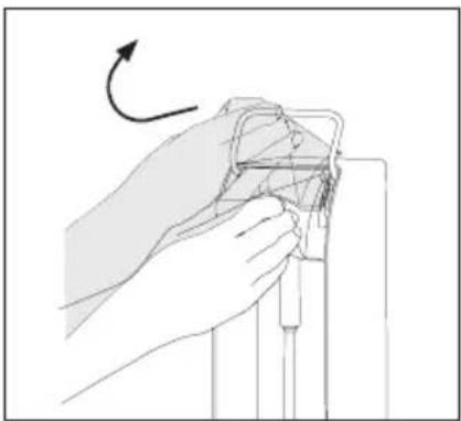
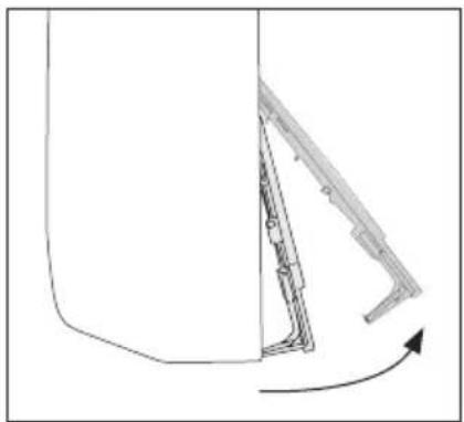
Open face shield. Therefore, pull it slightly to front and guide it upwards.
natural_image
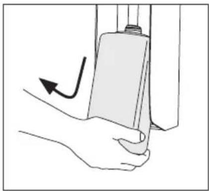
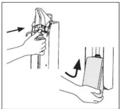
Illustration of a hand holding a device with an arrow indicating motion (no text or symbols)When delivered the mounting plate is in the dispenser. For the removal of the mounting plate slowly lift the receptacle in the dispenser and remove it from the dispenser.
natural_image
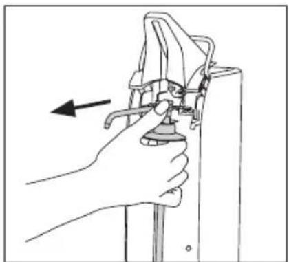
Illustration of a hand holding a tool with an arrow indicating direction (no text or symbols present)Remove the pump (see" pump change under point 9"), with opened face shield.

natural_image
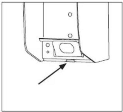
Illustration of hands using a tool to adjust or install a device, with an arrow indicating the process (no text or symbols present)Insert solid, thin object (for instance a screw driver) through the dismounting opening in the front side of the dispenser and press down the mounting tongue of the mounting plate. With pressed down mounting tongue pull off the dispenser from the mounting plate.

6. Mounting of the dispenser
natural_image
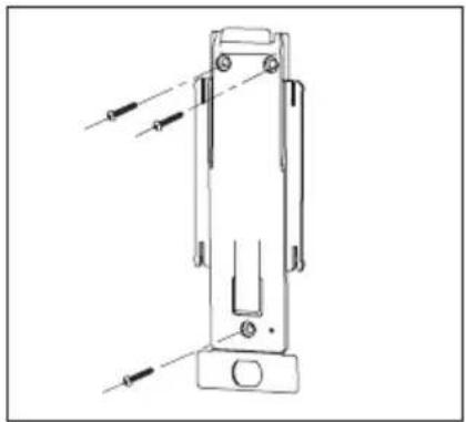
Technical line drawing of a mechanical device with mounting base and internal components (no text or symbols)Fix mounting plate at the wall in desired position by means of dowels and screws.
Drilling diagram see technical data (see point 17).
text_image
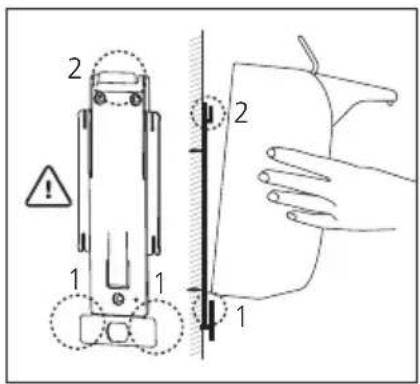
Technical diagram showing a device with labeled parts and warning symbols, including numbered components and a hand gesture.Slide the dispenser from above on to the mounting plate until it clicks into place.
natural_image
Illustration showing two hands performing a manual task: one holding a tool, the other handling a device (no text or symbols present)Reinsert first the pump and then the receptacle.
natural_image
Illustration of a hand holding a small mechanical component with an arrow indicating rotation (no text or symbols present)Close the face shield.

7. Going into operation
7. Going into operation
7.1 Insert the batteries
The dispenser has to be removed from the mounting plate (see removal of the mounting plate 6.2), the back of the dispenser must be easily accessible.
natural_image
Illustration of a hand holding a small object with a curved arrow indicating rotation (no text or symbols)Open face shield.
natural_image
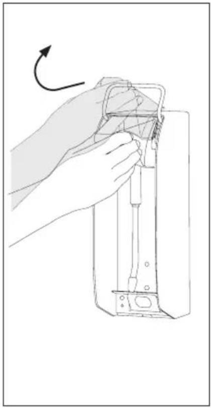
Technical line drawing of a mechanical bracket or mounting component with an arrow indicating direction (no text or symbols present)Open the cover of the battery case. To do that release the lower strap of the cover which is clipped in below the base angle. Then unhinge the cover and put it aside.
natural_image
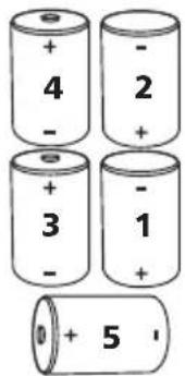
Pure mechanical component diagram without any text, numbers, or symbolsNow insert the batteries into the dispenser. Please pay attention to the correct polarity.
Keep the sequence as follows!
text_image
+ - 4 - 2 + 3 - 1 + 5• If the dispenser is not used for a longer period than 3 months, the batteries should be removed in order to prevent unwanted discharge.

7. Going into operation
• After correct insertion of the batteries an acoustic signal sounds.
- Slip the dispenser from above onto the mounting plate.
- Close the face shield:
now the dispenser starts with the first gauging.
- Noise level of the unit is below 70dB(A)
• If the batteries have not been inserted with closed face shield, the measuring procedure has to be carried out once again after having put the dispenser on the mounting plate by shortly opening and closing the runout diaphragm such as with the change and the insertion of the pump. This procedure will be explained below in more detail.
EN 7. Going into operation
natural_image
Line drawing of a hand using a tool to adjust or install a device, with no visible text or symbols.7.2 Use of the appliance
- With closed face shield it may happen during the change of the receptacle, that the lower sensor is actuated unintentionally when inserting the receptacle and medium penetrates. This can be prevented if the face shield remains opened during the change/insertion of the receptacle.
Whenever the face shield is closed, the dispenser adjusts to the pump and then to surrounding area. Therefore all parts of the body as well as all objects have to be removed rapidly from the immediate vicinity after having closed the face shield.
After the change of the receptacle and/or the pump the medium has to be pumped by repeated action (strokes).
During that hold the hand under the outlet.
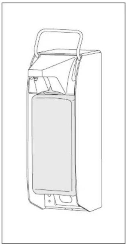
The LED lights while the dispenser gauges. As soon as the light is out the dispenser is ready for operation.
natural_image
Line drawing of a mechanical device with a handle and internal compartments (no text or symbols)- With the correct opening and closing of the face shield a different acoustic signal sounds each time.
- After the sliding on to the mounting plate the dispenser has to be adjusted to the pump and its environment – this happens automatically after each closing of the face shield at the end of the gauging procedure (as described above).
- If necessary, insert the pump.
- Now insert a receptacle with the suitable medium of your choice into the dispenser. Insert it from below via the pump and put the receptacle with the back edge of the bottom of the receptacle onto the base angle.
- Please make sure that the receptacle is in the right position and can't slip down out of the dispenser.
- Now you can use the appliance.

8. Basic operation
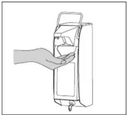
natural_image
Line drawing of a hand opening a cylindrical device with a handle and hook (no text or symbols)8. Basic operation
The actuation of the dispenser is effected if a hand approaches from below under the outlet. At a distance of approx. 4 cm the dispenser releases automatically a pumping process.
For this form a hollow with your hand.
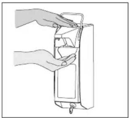
natural_image
Line drawing of hands installing or adjusting a device into a cylindrical container (no text or symbols)For further dispensing actions you can hold your lower hand within the lower sensor-controlled area and approach the second hand from above to the face shield ("virtual operating lever").
When actuating the dispenser with the second hand, please pay attention to that one hand remains under the outlet.
• If you approach with only one hand from above without holding the other hand below the outlet, the appliance does not pump.
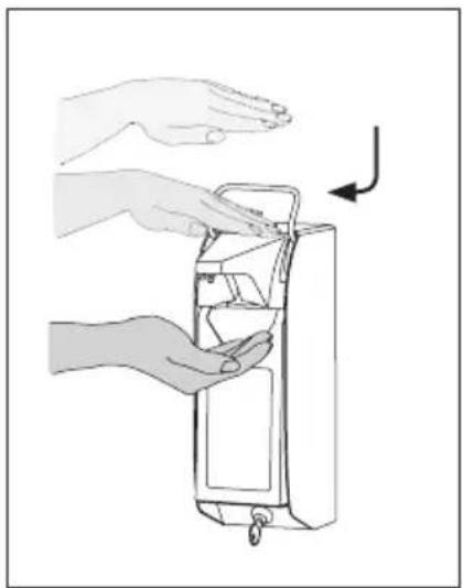
natural_image
Illustration of hands holding a device with a hand pointing to it, showing internal components and a directional arrow (no text or symbols)Approach the upper hand, to up to a distance of approx. 4 cm to the face shield – the dispenser actuates several times.
The dispenser meters as long as the upper hand is not removed - up to 5 times.
You may also approach your hand from above several times in sequence as if you actuated a virtual operating lever.
The pumping action is interrupted when removing both hands.
The complete action can be repeated as many times as you like.

9. Pump change
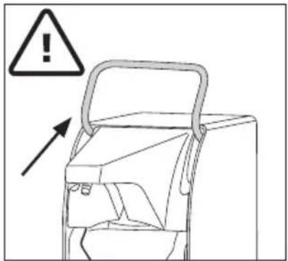
text_image
Diagram showing a device with warning symbol and an arrow pointing to it, indicating hazard or caution.9. Pump change
9.1 Exchange of the pump
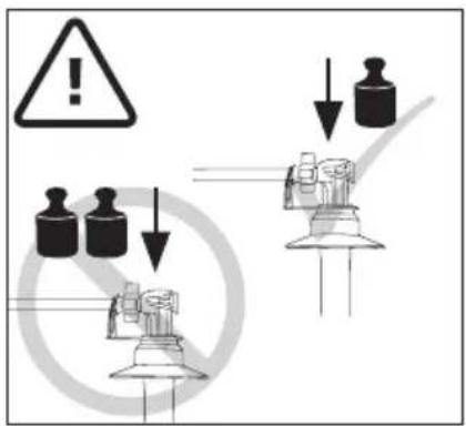
The pump can only be changed if the emergency operating lever is in upper position! Otherwise serious damages on the appliance may occur.
text_image
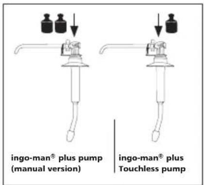
Safety warning diagram showing incorrect warning symbols and mechanical components with downward arrows indicating safety hazard.- Please take care that only original OPHARDT Touchless-pumps will be used. Do not use a pump of the type OPHARDT ingo-man® plus (with strong spring), because this might lead to damages at the dispenser.
text_image
ingo-man® plus pump (manual version) ingo-man® plus Touchless pumpYou can recognize the ingo-man® plus pump (manual version) by the fact that in contrast to the ingo-man® plus Touchless pump it develops a manually perceptible, relatively strong counter-pressure when pressing it down with the finger.
The ingo-man® plus Touchless pump, however, can be pressed down very easily.
text_image
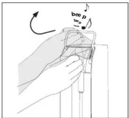
bee p bep pSwivel the face shield upwards (see 7.2). After the opening an acoustic signal sounds. When opening the face shield with the hand it is recommended to approach first with the hand from above (activation of the upper sensor area) in order to avoid unintentioned pumping actions.
EN 9. Pump change
natural_image
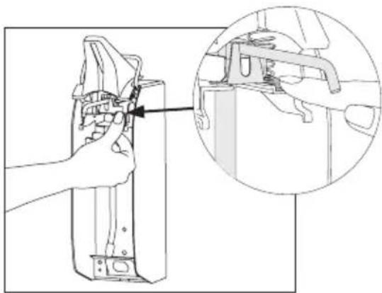
Technical line drawing of a mechanical assembly with an inset showing a close-up of a component detail (no text or symbols present)Push and hold the pump catch (key „PUSH“) with the finger and pull out the pump to the front.
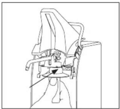
natural_image
Technical line drawing of a mechanical assembly with no visible text or symbolsPush in the pump from the front side into the intended guidance until it snaps in. Reclose the face shield.
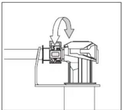
natural_image
Mechanical assembly diagram showing a rotating device with directional arrows indicating motion (no text or symbols)9.2 Change of the dosage
The dosage of the pump is adjusted to the maximum of approx. 1.5 ml/stroke. If required the dosage can be reduced in stages by turning the dosage piece (part of the pump) up to approx. 0,75 ml/stroke.
For this remove the pump from the dispenser.
natural_image
Illustration of a hand holding a device with an arrow indicating motion (no text or symbols)10. Exchange of receptacle
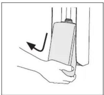
- Lift up the empty receptacle from below, draw it to the front and remove it from the dispenser.
- Insert the filled-up receptacle from below into the dispenser. Please pay attention to the correct position of the receptacle (see 7.2).
- If necessary, remove the locking plate before.
• In order to avoid unintentioned pumping actions, take care that the face shield is opened.

11. Operation with emergency operating lever
11. Operation with emergency operating lever
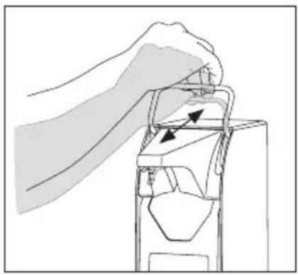
In case of a failure of the automatic functions (for instance batteries low), an operation by means of the emergency operating lever is possible.

- Only actuate the emergency operating lever in case of a failure of the automatic function!
natural_image
Illustration of a hand using a tool to adjust or install a mechanical component (no text or symbols visible)For this purpose press down the lever to the lower limit stop and return it again manually back up to the initial position.
natural_image
Line drawing of a mechanical device with a handle and base, showing no text or symbols12. LED display
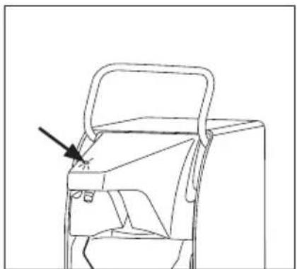
For protection against unintentioned actuation, electromagnetic interference sources and false handling are recognized and indicated by the lighting up of the LED. As long as the LED lights up, the automatic pumping action is suppressed.
i • The LED also lights up during gauging. When it expires, the dispenser is ready for operation.

13. Insertion of the locking plate
natural_image
Simple line drawing of a metal frame with a handle and mounting base (no text or symbols)13. Insertion of the locking plate
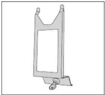
The locking plate is an optional accessory which prevents an unauthorized access to the medium.
text_image
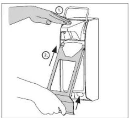
Diagram showing a hand holding a device with labeled parts, including numbered callouts and directional arrows indicating assembly or operation.- When inserting the locking plate the face shield has to be closed as it is locked, too.
- At first, hold one hand overneath the face shield in order to block unwanted pumping actions.
- Insert the sealing locking plate from below into the face shield.
natural_image
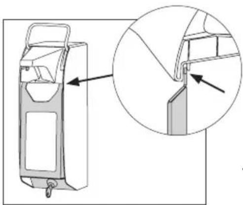
Technical line drawing of a mechanical device with an inset close-up showing a detail (no text or symbols)• Pay attention to the correct position in the face shield.
- Then insert the lock into the intended sparing (press the locking plate in the lower area towards the back) and lock up.
- For the removal proceed conversely.
i • Note:
During the insertion of the faceshield it can happen due to the handling that the acoustic battery level indication will be activated (see 14.2). Please don't be irritated in case that you hear several acoustic signals.

14. Maintenance / attendance and maintenance
14. Maintenance / attendance and maintenance
14.1 Cleaning and attendance
Please consider that also a high-quality product like this ingo-man® appliance requires attendance and care. The dispenser itself is maintenance-free with the exception of the battery exchange!
The Robert Koch Institute recommends: "Dispensers for soap and disinfectants must be thoroughly cleaned or sterilised whenever the cartridges are changed."
For cleaning the dispenser remove the mounting plate and dismount the batteries as it is described under 6.2. Cleaning of the dispenser only from the outside. Wipe the apparatus with a humid cloth.
Please only use warm soap water and do not use caustic (chlorous) purifiers or scouring powders!
In order to avoid operating errors during cleaning, we recommend to remove the receptacle and the pump out of the dispenser and to block the pumping function by actuating the upper sensor.
If the receptacle is filled up, a non-use during a longer period of time does not lead to an impairment. For that reason exchange the empty receptacle in time. If the suction valve is nevertheless clogged, please only pump hot water through it in order to restore the function.
⚠️ • By no means disassemble the appliance!
⚠️ · Please pay attention to that the appliance is not submerged or exposed to water jets.
natural_image
Two illustrations of a showerhead with shower spraying, one without a no-smoking symbol and the other with a shower spraying (no text or labels)The appliance is not autoclavable and cannot be cleaned in the dishwasher.
The pump itself is dishwasher-proof and autoclavable, however it must rest for about 6 hours after such a treatment before it is inserted again into the appliance.

14. Maintenance / attendance and maintenance
14.2 Exchange of battery
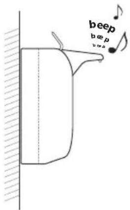
Test the battery level:
First of all approach one hand to the upper sensor and then the other hand to the lower sensor. Remain in this attitude for at least 3 seconds until the acoustic signal sounds:
text_image
beep beep$$ 4 x = \text { battery full } $$

$$ \underline {{3 x = ^ {3} / _ {4} f u l l}} $$

$$ \underline {{2 x = ^ {1} / _ {2} f u l l}} $$

$$ \mathbf {1} \mathbf {x} = ^ {1} / _ {4} \text { full } $$

i • In case of weak batteries during normal use a short acoustic signal sounds instead of the pumping action to indicate that the battery has to be replaced.
14.3 In time refill of the medium
For an interruption-free hygienic supply the receptacle has to be exchanged in time.

15. Risks and Troubleshooting
15.1 Risks and Troubleshooting
15.1 Risks
In dealing with the ingo-man® plus Touchless please take notice of some important differences compared to our manually operated dispensers of the ingo-man® product range, especially the ingo-man® plus (manual version):
- The ingo-man® plus Touchless is not autoclavable
- The pump of the ingo-man® plus can't be inserted into the ingo-man® plus Touchless, because this can lead to failure and defects on the appliance.
- The discharge diaphragm of the ingo-man® plus Touchless is not removable.
- The sealing diaphragm of the ingo-man® plus is not compatible with the ingo-ma® plus Touchless and vice versa!
Other risks:
- Never try to remove or to change the pump when the emergency operating lever is not locked in the upper position!
- The emergency operating lever has to be actuated only in case of a failure of the automatic function!
- Do not carry out any repair at the appliance!

15.2 Troubleshooting
| Characteristic | possible cause | solution |
| 1.| After insertion of the batteries no acoustic signal sounds | | Batteries are low. | Batteries have not been inserted correctly. | Face shield closed. | | Insert new batteries. | Open the battery box, insert batteries according to the diagram. Pay attention to the polarity and the sequence. | Remove batteries, open face shield, insert batteries again. |
| 2.| During opening and closing of the face shield no signal sounds | | Batteries are low. | No batteries inserted. | Battery contact interrupted. | Appliance defective. | | Insert new batteries. | Insert batteries. | Restore battery contact. | Call after-sales service. |
| 3.| The LED lights up if a hand is hold below the dispenser but no medium penetrates | | Operating error. | Appliance recognized a disturbance (unwanted emission or electric field). | | Operate appliance according to point 8. Pay attention to the sequence of actuation in the sensor areas. Avoid contact with the face shield. A) Remove all electromagnetically charged or emitting appliances out of the reach of the sensor. B) Open and close the face shield and quickly remove hands and/or other disturbing objects. Wait for a short time until the dispenser has gauged. Then actuate the dispenser as usual. C) Remove receptacle and pump and reinsert them. D) Make sure that the pump has the right position. |
| 4.| The appliance seems to function normally but no medium penetrates. | | No receptacle is inserted. | No pump is installed. | Pump is clogged. | Receptacle is empty. | Pump lost contact to the medium. | An unsuitable medium has been used. | | Insert full receptacle. | Insert ingo-man® plus Touchless pump into the dispenser. | Remove pump and clean it. | Replace receptacle. | Carry out the dosage process several times. If it doesn't function, the pump is possibly clogged. | Use another medium. Clean the pump thoroughly before. |
| 5.| An acoustic signal only sounds if the hand is hold below the lower sensor | | Batteries are low. | | Replace batteries. |
| 6.| After insertion of the locking plate the appliance does not function as usual. | | Appliance has not yet adjusted to the locking plate. | | Wait (maximum for a few minutes). |
| 7.| The appliance doses too much or not enough medium | | Dosage adjustment is not adjusted correctly. | | Carry out dosage adjustment on the pump |

16. Disposal
16. Disposal
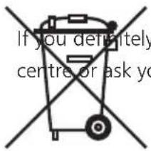
Dispose of the packing material into the corresponding recycling plants.
text_image
If you definitely centre or ask yo
17. Technical data
17. Technical data
Shroud aluminium, anodized
Lever stainless steel
Mounting plate synthetic material
Receptacle synthetic material, removable 1000 ml
Pump stainless steel and/or synthetics, removable
Wall mounting with dowels and screws
Voltage 7.5 volt DC
Batteries. 5 mono-cells type ANSI D
Safety class system IP22
Dimensions in mm W 92 x H 330 x D 210 mm
Total weight 1250 gram (without batteries)
Conformity RoHS compliant

Machinery directive 2006/42/EC
EMC- directive 2004 / 108 / EC
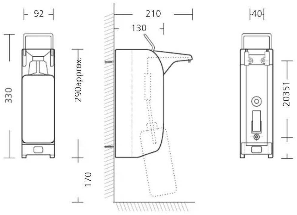
IMP T touchless | Dimensions (approx.) in mm | Technical modifications reserved.
Prior to the use of new filling media tests are required!
OPHARDT
hygiene
Ophardt Hygiene-Technik GmbH + Co. KG • Lindenau 27 • 47661 Issum • Germany
Phone +49 28 35 18-0 • Fax +49 28 35 18-77
Email info@ophardt.com • www.ophardt.com