
HD 701 AM - Hand dryers DIMPLEX - Free user manual and instructions
Find the device manual for free HD 701 AM DIMPLEX in PDF.


| Product Type | Hand Dryer |
| Brand | Dimplex |
| Model | HD 701 AM |
| Power Supply | 230 V AC, 50 Hz |
| Power Consumption | 1800 W |
| Airflow | 280 m³/h |
| Drying Time | Approx. 10 seconds |
| Activation | Automatic with infrared sensor |
| Dimensions (W x D x H) | 260 x 200 x 320 mm |
| Weight | 3.5 kg |
| Noise Level | ≤ 70 dB(A) |
| Housing Material | ABS plastic (anti-impact) |
| Filter | Washable pre-filter |
| Protection Class | IP23 |
| Safety Features | Thermal cut-out, overheat protection, automatic shut-off |
| Motor | Brushless DC motor |
| Installation | Wall-mounted, includes mounting kit |
| Maintenance | Clean filter monthly, wipe exterior with damp cloth |
| Warranty | 2 years |
Frequently Asked Questions - HD 701 AM DIMPLEX
User questions about HD 701 AM DIMPLEX
0 question about this device. Answer the ones you know or ask your own.
Ask a new question about this device
Download the instructions for your Hand dryers in PDF format for free! Find your manual HD 701 AM - DIMPLEX and take your electronic device back in hand. On this page are published all the documents necessary for the use of your device. HD 701 AM by DIMPLEX.
USER MANUAL HD 701 AM DIMPLEX
natural_image
Diagram showing two mechanical components: a fan-like device with rotational arrow and a hand pressing down on a rotating wheel (no text or symbols)natural_image
Technical line drawing of a mechanical device with no visible text or symbolsEndmontage
These installation and operating instructions should be read carefully and retained for future reference.
Ensure that these installation and operating instructions are passed on to any new owner.
Description of Hand Dryer
The sole purpose of the hand dryer is to dry hands. The hands are dried in a stream of warm air that flows out of the swivel nozzle. The hands can be rubbed together to accelerate drying.
The hand dryer is operated by a proximity switch which starts the unit automatically when hands are placed under the air outlet nozzle. When the hands are removed from the airflow, the proximity switch automatically stops the dryer after a run-on delay of approximately 2 seconds.
The hand dryer is designed to be mounted indoors only..
It must be mounted on a vertical wall with the air outlet opening pointing downwards.

The installation and electrical connection of the hand dryer may only be performed by a competent electrician!
All safety measures taken must conform to the applicable national regulations effective in the relevant country! The electrical supply circuit to the dryer must incorporate an all-pole isolating switch with at least 3mm contact clearance on each pole!
Technical Specifications
| Type HD 701 AM | |
| Operating voltage 220-240 V~50/60 Hz | |
| Rated power 2250 Watt | |
| Protection type IP 23 | |
| Class of protection I, with earnting conductor | |
| Type of connection | Fixed wiring or flexible cord |
| Type of mounting Wall mounting | |
| Operation | Proximity switch |
| Time delay | 2 seconds |
| Airflow rate | 470 m^3/h |
| Noise level | 70 dB (2 m) |
| Dimensions W x H x D | 276 x 245 x 210 mm |
| Weight | 4,7 kg |
Specifications subject to change without notice
Materials supplied with hand dryer
The hand dryer comes complete with a drilling template, special spanner and mounting hardware.
Installation
Recommended mounting height from the floor level to the bottom of the hand dryer: Adults 120 cm; wheelchair users, children 100 cm.
There must be a minimum clearance of 40 cm, in the direction of air discharge, from wall shelves, wash-basins, etc!
Avoid reflecting surfaces within the detection range of the sensor lens!
When choosing the installation location, make sure that the safety distances in accordance with the relevant national regulations are complied with!
With the special spanner (supplied in the small parts bag) turn the screws inside the casing cover in the base of the unit all the way in (in clockwise direction).
Swing out cover at the bottom and remove in upward direction.
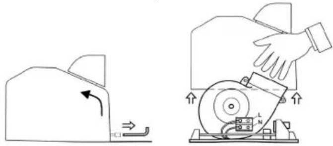
natural_image
Diagram showing two mechanical components: a device with a curved arrow and a hand pressing down on a rotating wheel (no text or symbols present)The packing box contains a drilling template with the dimensions of the mounting plate. Mount the hand dryer on a vertical wall with the air outlet opening pointing downwards, bearing in mind the mounting dimensions detailed below.
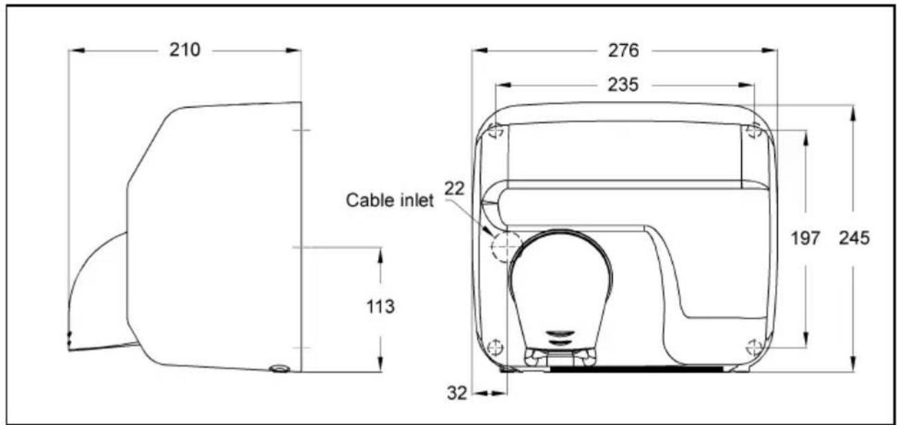
Dimensions in mm
Mark the location of the four mounting holes 235 mm x 197 mm (see illustration above).
Disconnect the relevant electrical circuit (shut off circuit breaker or remove fuse) before continuing with the mounting work! When inserting the wall plugs, be careful of existing electrical cables in the wall! Risk of electric shock!
However, special mounting materials may need to be used according to the construction of the wall (e.g. lightweight partition walls). Seek specialist advice. Drill ∅ 8 mm holes for the wall plugs and insert the plugs.
Strip the power supply cable (for fixed wiring) and feed it through the opening in the back plate of the device. Secure the back plate of the unit to the wall using the screws supplied.
Electrical Connection
Required conductor cross section 3 x 1.5 mm ^4 .
If a flexible power cord is used, the cord must be fed through the white cable entry and the cable gland supplied with the unit prior to installation. Firmly tighten the cable gland and secure it to the support (A) provided inside the unit. Strain relief is to be ensured! Connect phase conductor (L) and neutral conductor (N) to the terminal block. Pay attention to terminal markings.
Properly connect protective earth conductor to the base plate. When using a flexible power cord, a suitable cable lug, e.g. eye lug, is required.
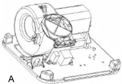
natural_image
Technical line drawing of a mechanical assembly with no visible text or symbolsFinal Assembly
Tilt casing cover somewhat toward the front and latch top of cover on to base plate. Slide white cable entry into casing cover recess. Tilt casing cover toward the rear. Firmly tighten fixing screws inside the unit by turning them to the left (in anticlockwise direction).
Operation

When in use, the air outlet grille gets hot. Do not touch or cover!
The hand dryer has a proximity switch which switches the dryer on automatically when hands are placed under the air outlet nozzle and switches off when the hands are removed from the hot airflow. There is a run-on delay of approximately 2 seconds. The sensitivity of the proximity switch can be reduced by turning the potentiometer on the electronic circuit board to the left (in anticlockwise direction). This must be carried out by a competent electrician. Please refer to the "Circuit Diagram" section overleaf for details.
Cleaning

Allow appliance to cool before carrying out any cleaning work! Wipe the outside of the unit the sensor lens (at the bottom of the air outlet nozzle) with a damp cloth and dry. Do not use austic or abrasive cleaning agents. The appliance should not be subjected to water spray.
Hold a vacuum cleaner against the air inlet openings and/or the air outlet nozzle to remove any dust that may have accumulated inside the unit.

The hand dryer casing may only be opened by a competent electrician!
Troubleshooting
| Problem Possible cause Remedy | ||
| Household fuse tripped. Check fuse. | ||
| No stream of hot air | Overheat protection tripped. Allow unit to | cool sufficiently. |
| Sensor lens of proximity switch has been deliberately covered (e.g. by chewing gum, adhesive tape, etc.). | Remove foreign matter from sensor lens, clean sensor lens of proximity switch. | |
| Sensor lens excessively dirty Clean sensor lens | ||
| Insufficient distance | from shelf. | Distance from shelf must be min. 400 mm. |
| Device switches on accidentally | Objects with reflecting surface within range of sensor | Remove objects |
| Sensitivity of proximity switch set too high. | To be carried out by a competent electrician: Reduce sensitivity (see section "Circuit Diagram"). | |
If the problem cannot be remedied using the methods described above, shut off the circuit breaker, or remove the fuse, and consult a competent electrician, or contact the After Sales Service detailed overleaf.

Repairs to the hand dryer should only be carried out by a competent electrician!
Circuit Diagram
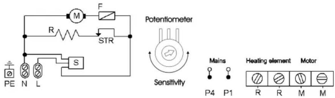
F Motor fuse P4, P1 Power supply, electronic
L Phase R Heating element
M Motor S Proximity switch
N Neutral conductor STR Safety cut-out, heating element
PE Protective earth conductor
Guarantee
This product is guaranteed for two years in accordance with our guarantee terms.
Disposal
The appliance must not be disposed of with household waste.
Brand : DIMPLEX
Model : HD 701 AM
Category : Hand dryers